software architecture for planetary & lunar robotics (utz).pdf · software architecture for...
TRANSCRIPT

Software Architecturefor Planetary & Lunar Robotics
Hans UtzResearch Institute for Advanced Computer Sciences at
Intelligent Robotics GroupNASA Ames Research Center
Terry FongIntelligent Robotics Group
NASA Ames Research Center
Issa A.D. NesnasJet Propulsion Laboratory
California Institute of Technology

Overview
• The Intelligent Robotics Group• Software architecture for space robotics• Challenges in rover interoperability• The CLARAty approach• CLARAty examples:
– Locomotion framework– Motor abstraction
• Future development• Summary and conclusions

Intelligent Robotics Group• Areas of expertise
– Applied computer vision – Human-robot interaction– Interactive 3D visualization– Robot software architectures
• Science-driven exploration – Survey, instrument placement, resource
mapping– Low speed, deliberative operation
• Fieldwork-driven operations– Assembly, inspection, maintenance– Pre-cursor missions (site preparation,
infrastructure emplacement, etc.)– Manned missions (human-paced
interaction, peer-to-peer assistance)

Robots and Facilities
K9
Rover lab
K10(4x)
K11
PER(10x)Scorpion
AmtecSchunk
(2x)
Marscape
Moonscape

Marscape• Outdoor rover test facility
– 3/4 acre, surveyed site– Operations trailer– dGPS, wireless LAN, power
• Mars analog– Design reflects geology of
scientific interest– Streambed, delta, lakebed,
volcano, chaotic terrain, meteorite impact crater, etc.
– Traversable + non-traversable regions (with occlusions)
40m
80m

Moonscape• Indoor rover test facility
– Human-Robot studies• Work area
– 37 x 45 ft with hip wall– Lunar mural & floor– Optical motion capture
• Control room– High-end graphics PC’s– Plasma touchscreen
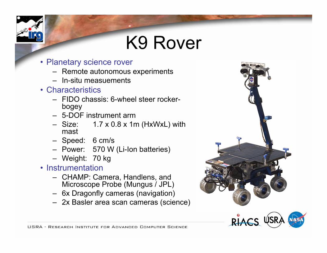
K9 Rover• Planetary science rover
– Remote autonomous experiments– In-situ measuements
• Characteristics– FIDO chassis: 6-wheel steer rocker-
bogey– 5-DOF instrument arm– Size: 1.7 x 0.8 x 1m (HxWxL) with
mast– Speed: 6 cm/s– Power: 570 W (Li-Ion batteries)– Weight: 70 kg
• Instrumentation– CHAMP: Camera, Handlens, and
Microscope Probe (Mungus / JPL)– 6x Dragonfly cameras (navigation)– 2x Basler area scan cameras (science)

K10 Rover• Field work rover
– Operational tasks (assembly, inspection, etc.)
– Human paced operations– Same avionics and software as K9
• Characteristics– 4-wheel steer rocker chassis– Low-cost (COTS parts)– Size: 0.6 x 0.7 x 1 m (HxWxL)– Speed: 0.8 m/s (10 deg slope)– Power: 1900 W (Li-Ion batteries) – Weight: 100 kg (30 kg payload)
• Development– 2004: initial build (Hsiu / Gogoco LLC)– 2005: rev. 2 build– 2006: locomotion redesign (Proto Innovations LLC)
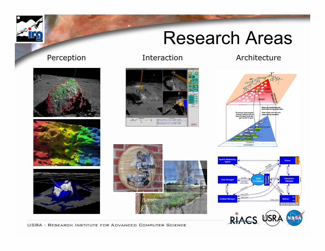
Research AreasArchitecturePerception Interaction

Robot Software Architectures• Almost no SW-reuse in flight software so far• And also in space robotics research
Rising demand for reusable robotics infrastructure:• The rising complexity of scenarios does not
allow reimplementation from scratch• Complexity of future applications goes beyond
the scope of a single research group• Code reuse enhances software quality• Code reuse allows focusing on the not yet
solved problems

Why develop reusable software?
• To capture robotic domain knowledge• To support development of generic
algorithms• To reduce the need for resolving recurring
problems for every system• To simplify integration of new technologies• To use same framework for various robots• Increase functionality by leveraging a
more mature base
Middleware for Space Robotics?
• Middleware does hardly meet today’s requirements of flight software and hardware– MHz, MB RAM– Software verification: No dynamic memory
allocation, no callbacks (virtual methods), no large external libraries
• CLARAty-based demonstrators were flight hardened for use on MER-rovers

CLARAtyCoupled Layer Architecture for Robotic Autonomy
CLARAty is a unified and reusable robotic software that provides basic functionality and simplifies the integration of new technologies on various rovers and robotic platforms
• Multi-center projectJPL, ARC, CMU
• Supports various rover platformsFido, Rocky 7, Rocky 8, K9, K10, (K11)
http://claraty.jpl.nasa.govSlides in co-operation with Issa Nesnas, JPL

NASA Develops Various Rovers
Large
Medium
Small For research & flight

Reconfigurable Robots
Would like to support …
Manipulators
COTS Systems
Custom Rovers
Problem and Approach• Problem:
– Difficult to share software/algorithms across systems– Different hardware/software infrastructure– No standard protocols and APIs– No flexible code base of robotic capabilities
• Objectives– Unify robotic infrastructure and framework– Capture and integrate legacy algorithms– Simplify integration of new technology– Operate heterogeneous robots– Mediate between research and flight requirements

Why is robotic software “hard”?
• Software:– Software is large and complex– Has lots of diverse functionality– Integrates many disciplines– Requires real-time runtime models– Has limited hardware resources - efficiency– Talks to hardware
• Hardware:– Physical and mechanics vary– Electrical hardware architecture changes– Hardware component capabilities vary

How?• Study several robotic system implementations• Study interactions of elements in various systems• Identify reusable elements in robotic systems• Identify implicit assumptions made • Project potential advances to these elements• Design a generic/flexible implementation of these
elements• Adapt to a number of robotic systems• Test and study the limitations of the design• Go back to design and iterate• Modify/extend/redesign to address limitations and
variability across systems
Your generic base is reusable

Approach
• Domain knowledge guides design• Layers of abstraction help master complexity• Abstractions also provide a classification of
various technology elements• Information hiding protects implementation
variability• Small modular components are more reusable
than monolithic blocks• Interfaces define behavior of various elements

Things to be aware of• Over-generalizing leads to ineffectiveness
– More general -> less functionality -> more work for results
– Number of abstractions vs. complex hierarchies– Modular elements with strongly typed interfaces– Algorithm generality influences abstraction design
• Runtime models vary across systems– Challenges in combining hardware/firmware/software
architectures in most effective manner– Need for both cooperative and pre-emptive
scheduling

Goals• Capture and integrate a wide range of
technologies• Leverage existing tools• Leverage experience and tools of the larger
software development community• Apply appropriate design patterns to the domain• Provide an infrastructure that enables rapid
robotic development• Capture experience of technologists
implementations

Challenges in Interoperability
! Mechanisms and Sensors! Hardware Architecture
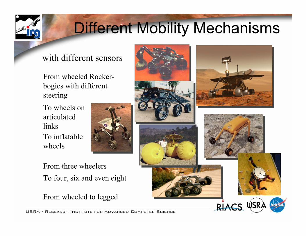
Different Mobility Mechanisms
with different sensors
From wheeled Rocker-bogies with differentsteering
From three wheelers
To inflatablewheels
To wheels onarticulatedlinks
From wheeled to legged
To four, six and even eight

For Example: Wheeled Locomotion
Rocky 7 Rocky 8
QuickTime™ and aNone decompressor
are needed to see this picture.
QuickTime™ and aVideo decompressor
are needed to see this picture.
QuickTime™ and aNone decompressor
are needed to see this picture.

Reusable Wheeled Locomotion Algorithms
Frontx
yzC
(a)Skid Steering
(no steering wheels)
Frontx
yz
C
(c)Two –wheel steering
Front
xy z
C
(e)All wheel steering
(e.g. MER, Rocky8, Fido, K9)
(f)Steerable Axle (e.g.Hyperion)
xy
z
C
(b)Tricycle
(one steering wheel)
Frontx
y z
(d)Partially Steerable
(e.g. Sojourner,Rocky 7)
ATRV (a) Sojourner (d)
Rocky 8 (e)
Rocky 7 (d)
K9 (e)
FIDO (e)
General flat terrain algorithms and specialized full DOF algorithms

Manipulators and Sensor SuitesCustom AnalogSun Sensor
3 Accelsz-axis gryo
6 DOF IMU
4 DOF Arm
4 DOF Mast
2 DOF Arm
3 DOF Mast
• Given different capabilities, how much reuse can be achieved?
Camera Sun Sensor
QuickTime™ and aNone decompressor
are needed to see this picture.

CLARAty Architecture

THE DECISION LAYER:Declarative model-based Mission and system constraintsGlobal planning
CLARAty = Coupled Layer Architecture for Robotic Autonomy
INTERFACE:Access to various levelsCommanding and updates
THE FUNCTIONAL LAYER:Object-oriented abstractionsAutonomous behaviorBasic system functionality
Adaptation to a system
A Two-Layered Architecture

Simulation Hardware Drivers
Adapting to a Rover
Generic Functional Layer
Rocky 8 Specialized
Classes&
Objects
Connector
Decision Layer
Multi-level access Connector
Rocky 8Models/
Heuristics

The Decision Layer
Executives(e.g. PLEXIL)
General Planners(e.g. CASPER)
Activity Database
Rover Models
FL Interface
Plans
• The different application scenarios provide a high degree of variability in the design of the decision layer
• Plan centric vs. interactivity centered architectures have different requirements on the functional layer
• The DL/FL interfacing is therefore a critical part of the robot architecture

The Functional Layer
Transforms
Motion Control
VisionEstimation
Input/Output
Manipulation
Navigation
Communication
Math
Hardware Drivers
Locomotion
Rover
Behaviors
Path Planning
Rocky 8
Rocky 7
K9
FIDO
Science
Simulation
Sensor
Adaptations
K 10

Functional Layer Components
Pixel
MastWheeledLocLeggedLoc RBLoc
Locomotor
CoordMotors
SocketMotor
Camera
Instrument
BBMotorControlledMotor
Analog_IODigital_IO
IO
VisualNavigatorVisualTracker
Array_2D
Vector Location Point
Matrix
ImageColorImage HTrans
FeatureDetectorCorrelator
BehaviorState
Database Bit
Resource
Rover
SocketMsg
Manipulator
Arm
StereoGen
Specialized Data Structures
General Purpose Data Structures
Standard Template LibraryString
LinkedList
Container
Waypoint
PathCamera Image
Location
Connector
Abstraction Models

CLARAty Abstractions• Generic Physical Components (GPC)
– Locomotor, Arm, Mast, • Specialized Physical Components
(SPC)– K9_Locomotor, K9_Arm, R8_Mast
• Generic Functional Components (GFC)– ObjectFinder, VisualNavigator,
Stereovision, Localizer• Specialized Functional Components
(SFC)

Generic Technologies & Algorithms
• Technologies that are generic by design should not be constrained by the software architecture & implementation
• Non-generic technologies should be accommodated on the appropriate platforms– Example (Generic): if you are working in navigation,
you would not care about H/W architecture difference among different rovers
– Example (Specific): if you are doing wheel/terrain interaction research, you might require specific hardware which one of the vehicles would support
• Assumptions are made explicit

Wheel Locomotor Example

Capabilities of Wheel Locomotor
• Type of maneuvers:– Straight line motions (fwd / bkwd)– Crab maneuvers– Arc maneuvers– Arc crab maneuvers– Rotate-in-place maneuvers (arc turn r=0)
• Driving Operation – Non-blocking drive commands– Multi-threaded access to the Wheel_Locomotor class – e.g. one
task can use Wheel_Locomotor for driving while the other for position queries
– Querying capabilities during all modes of operation. Examples include position updates and state queries
– Built-in rudimentary pose estimation that assumes vehicle follows commanded motion
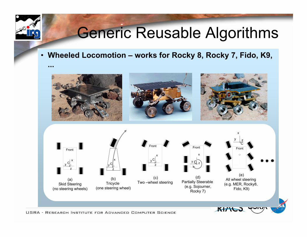
• Wheeled Locomotion – works for Rocky 8, Rocky 7, Fido, K9, ...
Front
xy
z
C
(a)Skid Steering
(no steering wheels)
x
yz
C
(b)Tricycle
(one steering wheel)
Front
x
y zC
(d)Partially Steerable
(e.g. Sojourner,Rocky 7)
Front
x
y zC
(e)All wheel steering
(e.g. MER, Rocky8, Fido, K9)
Front
x
yz
C
(c)Two –wheel steering
Generic Reusable Algorithms

R7 Specific Rover Implementation
MastWheeledLocLeggedLoc RBLoc
Locomotor
CoordMotionSystem
Motor
BBMotorControlledMotor
Analog_IODigital_IO
IO
Manipulator
Arm
R7_Arm R7_Mast
Implements general fwd &inv. kinematics & joint ctrl
•Specialized inv. Kinematics (overrides default)•Attaches proper motors•Attaches proper cameras for mast•Adds filter wheel
R7_Locomotor
•Attaches proper motors•Restricts Steering to 2 wheels
LM629ChipLM629Motor
R7_Rover
R7_Arm
R7_MastR7_Locomotor
R7
Device Drivers
VPAR10Board
Non reusable Code Reusable Code

R8 Specific Rover Implementation
MastLeggedLoc Wheeled Locomotor
Locomotor
CoordMotionSystem
Motor
BBMotorControlledMotor
Analog_IODigital_IO
IO
Manipulator
Arm
R8_Arm R8_Mast
Implements general fwd &inv. kinematics & joint ctrl
•Specialized inv. Kinematics (overrides default)•Attaches proper motors•Attaches proper cameras for mast•Adds filter wheel
R8_Locomotor
•Attaches proper motors•Restricts Steering to 2 wheels
R8_Motor
R8_Rover
R8_Arm
R8_MastR8_Locomotor
R8
Widget Board
Widget AIOWidget DIO
Widget Motor HCTL 1100 Chip
Non reusable Code Reusable Code
Trajectory
Trajectory_GeneratorTimers

Analysis of amount of reusable code across implementations:
-Reusable131Point 2DReusable2080Controlled Motor
-Reusable1083Matrix, Vector, Array
Rotation Matrix, Point 2DReusable341Location, Homogeneous Transforms
-Reusable435Rotation Matrices
584 (non-reusable)
Non-reusableNon-reusable
Reusable
Reusable
Reusable
Status
Widget Motor, etc...Rocky 8 Motor
-
Vector
Motion Sequence, 1D Solver, Homogeneous Transforms
Depends On
~92%Total Reusable6995Total334Rocky 8 Motor250Rocky 8 Locomotor
3561D Solver
540Motion Sequence
1445Wheel Locomotor
Lines of CodeModule
Code Reusability Results

Motor Example

Example: Generic Controlled Motor
• Define generic capabilities independent of hardware
• Provide implementation for generic interfaces to the best capabilities of hardware
• Provide software simulation where hardware support is lacking
• Adapt functionality and interface to particular hardware by specialization inheritance
• Motor Example: public interface command groups:– Initialization and Setup– Motion and Trajectory– Queries– Monitors & Diagnostics
Time
Velo
city
S- Profile
Instantaneous Profile Change

Comparing Different Implementations
Controlled_Motor_Impl
ControlledMotor
Linear_AxisJoint
Non-Resuable Layer R8_MotorR7_MotorFido_Motor Sim_Motor
Trajectory
Trajectory_Generator
Mz<Type>
HCTL_Chip
LM629_Chip
Widget_BoardR7_MC_Board
Widget_Motor
PID_Servo

• Actual Examples of Code Reusability for Hardware modules:– Controlled Motor Hierarchies for Rocky 8 and Rocky7
~95%Total Reusable
334 (non-reusable)6380Total
~52%Total Reusable – Strict
Reusable –widget
383Widget Motor
Reusable – I2C1446I2C Master
Reusable – HCTL900Motor Controller HCTL
Non-reusable334Rocky 8 MotorReusable756BitsReusable143Resources (Timers, etc)Reusable338Trajectory GeneratorReusable2080Controlled Motor
StatusLines of Code
Module
Reusable – VPAR10534VPAR10 Parallel I/O
546 (non-reusable)5636Total~90%Total Reusable
Non-reusable131Rocky 7 I/O MapsNon-reusable415Rocky 7 Motor
~63%Total Reusable – Strict
Reusable – LM6291014Motor Controller LM629
Reusable706Input OutputReusable756BitsReusable2080Controlled Motor
StatusLines of CodeModule
yModules
Rocky 8 Rocky 7

Solaris/Linux
Motorola 68K
Intel x86
Ames
JPL
CMU
Rocky 8
Intel x86
VxWorks
VxWorks
Linux
Rocky 7
K9
JPL
ROAMS
JPL
Linux
Intel x86
JPL AISolaris CC
Currently Supported Platforms
AmesIntel x86
Linux
K10

Future Plans• Open Source Release• Flexible, freely configurable locomotion
system and mechanisms model• CORBA based functional Layer/Decision
Layer interfacing• Extend the architecture to the
requirements of the challenges of Lunar Robotics

Mars RoversCLARAty design originates primarily in Marsian scenarios:• Communication delay requires high amount of autonomy• Very limited system resources• No interaction possible
" An extremely autonomous mobile rover system
Scenario assumptions:• Single rover in an otherwise static world• Limited communication (up/down-link based)• Operation speed vs. operation safety tradeoff
" Limited reactivity

Lunar Challenges• High Bandwidth, low latency links
– Extensive communication– Limited teleoperation– Supervisor feedback augments autonomy
• Multiple robots– Team communication– Multi-robot cooperation
• Human robot interaction– Safety requirements– Speed requirements– Reactivity requirements– Single actor assumption breaks– Flexible task allocation

Summary• Space is a challenging application area for mobile robots• CLARAty provides a repository of reusable software
components at various abstraction levels• It captures well-known robot technologies in a basic
framework for researchers• It allows researchers to integrate novel technologies at
different levels of the architecture• It is a collaborative effort within the robotics community• It runs on multiple heterogeneous robots• The lunar mission provides new challenges for CLARAty

Acknowledgements
CLARAty Team (multi-center)
Jet Propulsion Laboratory
Ames Research Center
Carnegie Mellon University
Thank you very much for your attention!