software continuous technology refresh product improvement ... · 2.1 key requirements / needs ......
TRANSCRIPT
This document includes data that shall not be duplicated, used, or disclosed – in whole or in part – outside the Government for any purpose other than to the extent provided in contract DG133W-05-CQ-1067. However, the Government shall have the right to duplicate, use, or disclose the data to the extent provided in the contract. This restriction does not limit the Government’s right to use information contained in this data if it is obtained from another source without restriction. The data subject to this restriction are contained in all sheets.
Software Continuous Technology Refresh
Product Improvement Plan
Version 3
Document No. AWP.PLN.SWPIP-03.00 22 June 2007
Prepared Under
Contract DG133W-05-CQ-1067 Advanced Weather Interactive Processing System (AWIPS)
Operations and Maintenance
WBS 42011, OST-06-0010
Submitted to:
Ms. Anita Middleton Contracting Officer
U.S. Department of Commerce NOAA/NWS Acquisition Management Division
SSMC2, Room 15318 1325 East-West Highway Silver Spring, MD 20910
By:
Raytheon Technical Services Company LLC 8401 Colesville Road, Suite 800
Silver Spring, MD 20910
AWIPS Software CTR Product Improvement Plan, Ver. 3, June 22, 2007
Contract DG133W-05-CQ-1067; DCN AWP.PLN.SWPIP-03.00 Use or disclosure of data contained on this sheet is subject to the restriction on the title page of this document. ii
Table of Contents Page
1. Introduction............................................................................................................................... 1 1.1 Background................................................................................................................. 1 1.2 Purpose of the Product Improvement Plan ................................................................. 1
2. Strategy ..................................................................................................................................... 3 2.1 Key Requirements / Needs.......................................................................................... 3 2.2 Task Order Management Approach............................................................................ 4 2.3 Approach to Re-Architecture...................................................................................... 6 2.4 Roadmap ..................................................................................................................... 6
3. AWIPS II Architecture ........................................................................................................... 10 3.1 Introduction............................................................................................................... 10 3.2 Conceptual Architecture: Target State...................................................................... 10 3.3 AWIPS Service Oriented Architecture ..................................................................... 11 3.4 Key AWIPS II Features ............................................................................................ 17 3.5 AWIPS II Implementation Approaches / Features ................................................... 23 3.6 Security Considerations ............................................................................................ 25 3.7 Technical Risks and Mitigations............................................................................... 26
4. Project Management ............................................................................................................... 28 4.1 Assumptions.............................................................................................................. 28 4.2 Organization.............................................................................................................. 28 4.3 Risk and Opportunity Management .......................................................................... 29 4.4 Decision Management: Governance ......................................................................... 30 4.5 Technical (Management) Controls ........................................................................... 30 4.6 Integrated Master Plan; Integrated Master Schedule ................................................ 31 4.7 Facilities and Capital Equipment .............................................................................. 31 4.8 Formal Reviews and Reporting ................................................................................ 32
5. Software Development............................................................................................................ 33 5.1 Software Configuration Management....................................................................... 33 5.2 Testing....................................................................................................................... 33 5.3 Documentation.......................................................................................................... 33 5.4 Standards................................................................................................................... 33 5.5 Tools ......................................................................................................................... 34 5.6 Backup and Recovery ............................................................................................... 34 5.7 Security (Information Assurance)............................................................................. 34
6. AWIPS Software Migration.................................................................................................... 35 6.1 Migration Approach.......................................................................................................... 35 6.2 Migration Task Order Summary Descriptions.................................................................. 37 6.3 Special Topics................................................................................................................... 39 6.3 Local Applications (LA) ................................................................................................... 40 6.4 Documentation.................................................................................................................. 41 6.5 DR Processing................................................................................................................... 42
7. Migration Risks....................................................................................................................... 43 8. Training................................................................................................................................... 44
8.1 Developer Training – Suggested Approach...................................................................... 44 8.2 Developer Training Syllabus ............................................................................................ 45
AWIPS Software CTR Product Improvement Plan, Ver. 3, June 22, 2007
Contract DG133W-05-CQ-1067; DCN AWP.PLN.SWPIP-03.00 Use or disclosure of data contained on this sheet is subject to the restriction on the title page of this document. iii
8.3 System Administration Syllabus....................................................................................... 46 8.4 Training Support Task Order Description ........................................................................ 46
9. Deployment............................................................................................................................. 47 10. Transition to O&M ................................................................................................................. 48
10.1 Release Management ...................................................................................................... 48 10.2 SWIT, CM, and Test Environment Transition................................................................ 49 10.4 Application Maintenance ................................................................................................ 50 10.5 NCF and User Support.................................................................................................... 50 10.6 Governance ..................................................................................................................... 50
11. Government Testing................................................................................................................ 51
List of Tables Page
Table 3-1. Open Source Project Usage in AWIPS II.................................................................... 18 Table 3-2. Additional AWIPS II Implementation Approaches/Features...................................... 24 Table 3-3. AWIPS II: Technical Risks/Mitigations...................................................................... 26 Table 6-1. Task Order Themes ..................................................................................................... 36 Table 6-2. Discrete Function Summary ........................................................................................ 36
List of Figures Page
Figure 2-1. ADE Release Content .................................................................................................. 7 Figure 2-2. SW CTR Overall Roadmap.......................................................................................... 8 Figure 2-3. O&M Transition and Deployment Area Zoom-In ....................................................... 9 Figure 3-1. Conceptual Architecture Target State Rendering ...................................................... 11 Figure 3-2. System Capabilities Available as Network Services ................................................. 12 Figure 3-3. Services Organized Into Containers With Loose Coupling ....................................... 13 Figure 3-4. Container-Based Processing....................................................................................... 14 Figure 3-5. Services Composed of Components........................................................................... 14 Figure 3-6. Interface Details Abstracted Away From Services .................................................... 15 Figure 3-7. Interfaces Defined in Well-Known Data Model ........................................................ 16 Figure 3-8. Event-Driven Services ............................................................................................... 17 Figure 3-9. AWIPS II System Concept......................................................................................... 19 Figure 3-10. Common AWIPS Visualization Environment (CAVE)........................................... 20 Figure 3-11. Extensibility Enabled by Plug-Ins for Data Types and Transforms ........................ 22 Figure 3-12. Extending Local Capability via Scripting ................................................................ 22 Figure 3-13. Data Type-Independent Metadata Indexing and Query ........................................... 23 Figure 4-1. AWIPS SW CTR Project Organization ..................................................................... 29 Figure 4-2. Risk / Opportunity Management Tool ....................................................................... 30 Figure 10-1. AWIPS I Release Management Process .................................................................. 49
AWIPS Software CTR Product Improvement Plan, Ver. 3, June 22, 2007
Contract DG133W-05-CQ-1067; DCN AWP.PLN.SWPIP-03.00 Use or disclosure of data contained on this sheet is subject to the restriction on the title page of this document. iv
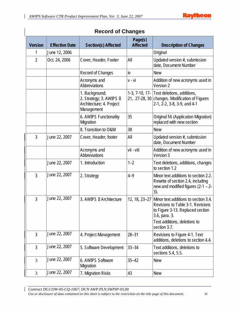
Record of Changes
Version Effective Date Section(s) Affected Page(s) Affected Description of Changes
1 June 12, 2006 Original 2 Oct. 24, 2006 Cover, Header, Footer All Updated version #, submission
date, Document Number Record of Changes iv New Acronyms and
Abbreviations v - vi Addition of new acronyms used in
Version 2 1. Background;
2. Strategy; 3. AWIPS II Architecture; 4. Project Management
1-3, 7-10, 17-21, 27-28, 30
Text deletions, additions, changes. Modification of Figures 2-1, 2-2, 3-8, 3-9, and 4-1
6. AWIPS Functionality Migration
35 Original §6 (Application Migration) replaced with new section
8. Transition to O&M 38 New 3 June 22, 2007 Cover, Header, footer All Updated version #, submission
date, Document Number Acronyms and
Abbreviations vii - viii Addition of new acronyms used in
Version 3 June 22, 2007 1. Introduction 1–2 Text deletions, additions, changes
to section 1.2 3 June 22, 2007 2. Strategy 4–9 Minor text additions to section 2.2.
Rewrite of section 2.4, including new and modified figures (2-1 – 2-3).
3 June 22, 2007 3. AWIPS II Architecture 12, 18, 23–27 Minor text additions to section 3.4. Revisions to Table 3-1. Revisions to Figure 3-13. Replaced section 3.6, para. 3. Text additions, deletions to section 3.7.
3 June 22, 2007 4. Project Management 28–31 Revisions to Figure 4-1. Text additions, deletions to section 4.4.
3 June 22, 2007 5. Software Development 33–34 Text additions, deletions to sections 5.4, 5.5.
3 June 22, 2007 6. AWIPS Software Migration
35–42 New
3 June 22, 2007 7. Migration Risks 43 New
AWIPS Software CTR Product Improvement Plan, Ver. 3, June 22, 2007
Contract DG133W-05-CQ-1067; DCN AWP.PLN.SWPIP-03.00 Use or disclosure of data contained on this sheet is subject to the restriction on the title page of this document. v
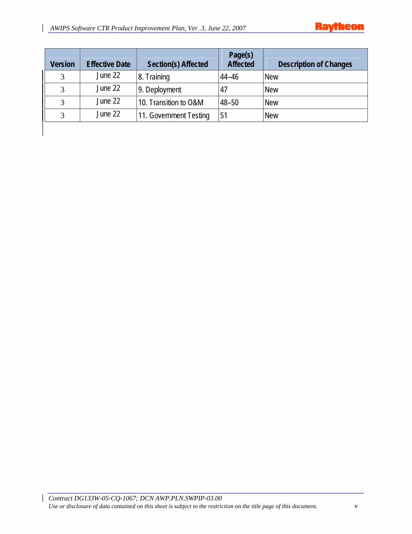
Version Effective Date Section(s) Affected Page(s) Affected Description of Changes
3 June 22 8. Training 44–46 New 3 June 22 9. Deployment 47 New 3 June 22 10. Transition to O&M 48–50 New 3 June 22 11. Government Testing 51 New
AWIPS Software CTR Product Improvement Plan, Ver. 3, June 22, 2007
Contract DG133W-05-CQ-1067; DCN AWP.PLN.SWPIP-03.00 Use or disclosure of data contained on this sheet is subject to the restriction on the title page of this document. vi
Acronyms and Abbreviations Used in This Plan ADE AWIPS Development Environment AE AWIPS Evolution AELC AWIPS Evolution Leadership Committee ASM Application Support & Maintenance AIFM AWIPS Integration Framework Manual AWC Aviation Weather Center C&A Certification and Accreditation AWIPS Advanced Weather Interactive Processing System CAVE Common (AWIPS) Visualization Environment CM Configuration Management CMP Configuration Management Plan CONOPS Concept of Operations COTS Commercial-Off-The-Shelf CPU Central Processing Unit CSCI Computer Software Configuration Items CTR Continuous Technology Refresh D2D Display 2-Dimensional DCS Design Change Specification DMZ Demilitarized Zone DR Discrepancy Report EDEX Electronic Data Exchange System ESA Electronic Systems Analyst ESB Enterprise Service Bus FEWS Flood Early Warning System FFP Firm Fixed Price GFE Graphical Forecast Editor GIS Geographical Information System GSD Global Systems Division GUI Graphical User Interface HMI Human Machine Interface HQ Headquarters HTTPS Hypertext Transfer Protocol Secure ICD Interface Control Documents IDE Integrated Development Environment IMET Incident Meteorologist IMP Integrated Master Plan IMS Integrated Master Schedule I/O Input/Output IRAD Internal Research and Development IT Information Technology ITO Information Technology Officer IV&V Independent Validation & Verification IWT Integrated Working Team JMS Java Messaging Service JVM Java Virtual Machine
AWIPS Software CTR Product Improvement Plan, Ver. 3, June 22, 2007
Contract DG133W-05-CQ-1067; DCN AWP.PLN.SWPIP-03.00 Use or disclosure of data contained on this sheet is subject to the restriction on the title page of this document. vii
LA Local Application KAP Knowledge Acquisition Process LDAD Local Data Acquisition and Dissemination METAR Meteorological Aviation Report MPLS Multi-Protocol Label Switching NAS Network Attached Storage N-AWIPS NCEP-Advanced Weather Interactive Processing System NC National Center NCF Network Control Facility NCEP National Centers for Environmental Prediction NOAA National Oceanic and Atmospheric Administration NWS National Weather Service NWSTD National Weather Service Training Division O&M Operations & Maintenance OB Operational Build ORION One Raytheon Integrated On-demand Network OSIP Operations and Services Improvement Process OST Office of Science and Technology OTE Operational Test and Evaluation PIP Product Improvement Plan PIPT Partnership Integrated Product Team PIT Pre-Integration Test PMP Program Management Plan POC Point of Contact QAP Quality Assurance Plan R&D Research and Development RAMP Risk Assessment and Management Planning RAOB Radiosonde Observation RCP Rich Client Platform RDBMS Relational Database Management System RFC River Forecast Center RHEL Red Hat Enterprise Linux ROM Rough Order of Magnitude RRD Risk Reduction Demonstration RTM Requirements Traceability Matrix SBN Satellite Broadcast Network SDK Software Developers Kit SDP Software Development Plan SEC Systems Engineering Center SEDA Serial Event-Driven Architecture SEMP System Engineering Management Plan SHEF Standard Hydrological Exchange Format SMM AWIPS System Manager’s Manual SLOC Software Lines of Code SOA Service Oriented Architecture SSDD AWIPS System/Subsystem Design Description
AWIPS Software CTR Product Improvement Plan, Ver. 3, June 22, 2007
Contract DG133W-05-CQ-1067; DCN AWP.PLN.SWPIP-03.00 Use or disclosure of data contained on this sheet is subject to the restriction on the title page of this document. viii
SSL Secure Sockets Layer SW Software SW CTR Software Continuous Technology Refresh SWIT Software Integration and Test TAF Terminal Aerodrome Forecast TCO Total Cost of Ownership TIM Technical Interchange Meeting TO Task Order UM AWIPS User’s Manual TP Test Plan UFT User Functional Test URI Universal Resource Identifier VTEC Valid Time Event Code WAN Wide Area Network WBS Work Breakdown Structure WFO Weather Forecast Office WSO Weather Service Office WX Weather XML eXtendible Markup Language
AWIPS Software CTR Product Improvement Plan, Ver. 3, June 22, 2007
Contract DG133W-05-CQ-1067; DCN AWP.PLN.SWPIP-03.00 Use or disclosure of data contained on this sheet is subject to the restriction on the title page of this document. 1
1. Introduction
1.1 Background In 2004, the National Oceanic and Atmospheric Administration (NOAA) National Weather Service (NWS) conducted a “present state” analysis of the Advanced Weather Interactive Processing System (AWIPS). The analysis raised several issues related to AWIPS software and indicated that AWIPS’ ability to support the future NWS mission was at risk. The analysis also pointed to a growing backlog in the development of new science capabilities, including data types, and raised concerns about the lengthy and tenuous Operational Build (OB) installation process. The ultimate conclusion was that AWIPS “software was in critical need of improvement.” Moreover, no Product Improvement Plan existed to address this critical need. NOAA presented the results of the AWIPS present state analysis to Raytheon during the Due Diligence period that preceded the submission of proposals to support AWIPS Operations and Maintenance (O&M). Based on the information provided during the presentation and on our own follow-up research, Raytheon proposed to make several improvements to the overall AWIPS software development and release processes – all of them predicated on migrating AWIPS software to a modern Services Oriented Architecture (SOA). Raytheon’s proposal, which resulted in the award of Contract DG133W-05-CQ-1067 in August 2005, included an offer to develop and produce a Software Product Improvement Plan (PIP) as the first step of the migration. This document constitutes that plan, which we will execute under contract Option 1, AWIPS Continuous Technology Refresh (CTR). The CTR option includes hardware, software, and telecommunications.
The following terms, all of which are used frequently throughout the PIP and elsewhere, require definition to avoid confusion.
• Software Continuous Technology Refresh (SW CTR) refers to the project described in this Product Improvement Plan, and is focused on the migration of AWIPS baseline software.
• AWIPS II refers to the migrated AWIPS system. • AWIPS Evolution (AE) refers to the overall evolution of AWIPS, including software,
hardware, and communications. AWIPS Evolution also refers to the functional organization of the Raytheon AWIPS Program that is concerned with the Continuous Technology Refresh of AWIPS. Each encompasses the same scope.
1.2 Purpose of the Product Improvement Plan The purpose of this Software CTR Product Improvement Plan (PIP) is to document and formalize the multiyear SW CTR project. The PIP describes the AWIPS Software Architecture target state and the plan to realize that state. It accounts for more current and complete information than was available for proposal preparation.
The PIP will provide a mechanism for communicating project scope, objectives, and details to the sizable and widely dispersed community of AWIPS stakeholders. These stakeholders will share ownership of the PIP with the NWS AWIPS Program and Raytheon, and will have both visibility into the plan and the ability to provide feedback at any time.
AWIPS Software CTR Product Improvement Plan, Ver. 3, June 22, 2007
Contract DG133W-05-CQ-1067; DCN AWP.PLN.SWPIP-03.00 Use or disclosure of data contained on this sheet is subject to the restriction on the title page of this document. 2
The PIP will associate the SW CTR plan with other events – Operational Builds, the Operations and Services Improvement Process (OSIP), other AWIPS system infrastructure changes (e.g., network, hardware), and Science and Technology – in order to provide a larger context and enable synchronization with related efforts.
PIP updates will be issued, as required, to keep the Plan current. If appropriate, the updates may be released as Task Order deliverables. If material new information is discovered, or if conditions change, the Plan can change to accommodate it.
The PIP identifies and describes tasks at a Master Plan or Strategy level of detail. Project specifics, such as detailed schedules, will be provided in individual Task Orders. Technical briefings, software demonstrations, training materials, source code, and documentation were delivered to the NWS with Task Orders 3, 4, 5, and 6. Other briefings have been given to the NWS as well (e.g., Corporate Board). Individuals desiring more detailed information are encouraged to review this material. Jason Tuell ([email protected]; 301.713.1809 x. 112) and Ronla Henry ([email protected]; 301.713.0211 x. 140) are Points of Contact for this information.
AWIPS Software CTR Product Improvement Plan, Ver. 3, June 22, 2007
Contract DG133W-05-CQ-1067; DCN AWP.PLN.SWPIP-03.00 Use or disclosure of data contained on this sheet is subject to the restriction on the title page of this document. 3
2. Strategy
2.1 Key Requirements / Needs System-Level Requirements/Needs. The existing end-user functionality of AWIPS appears to be comprehensive and adequate for current needs. Of concern to NWS, however, are the cost, complexity, and rapidly increasing difficulty of extending AWIPS’ functionality to meet the future mission of NWS and adapt to evolving end user and consumer requirements. NWS cited several system-level issues during the Due Diligence presentation on the “AWIPS Present State Analysis.” Those issues are the basis for the following list of major system-level requirements / needs:
• Improved adaptability to accommodate new science, new data types, and a changing CONOPS (to include new requirements in interagency collaboration).
• Maximum use of Open Source software vs. licensed Commercial-Off-the-Shelf (COTS) and proprietary software.
• Platform independence (hardware, operating system, database). • Improved reliability, availability, and supportability.
− Reduced Discrepancy Reports (DR). − Faster fix cycles.
• Improved performance, scalability (up and down), and load balancing. • Improved flexibility. • Simpler software build and deployment framework. • Streamlined installation process, including application releases. • Consistent user interfaces across applications (includes applications of Weather Forecast
Offices (WFO), River Forecast Centers (RFC), and the National Centers for Environmental Prediction (NCEP).
• Improved software consistency across independent developers. • Improved support for including local applications in site installations. • Standard development environment for all developers. • Improved compliance with standards.
As we meet these system-level requirements, current end-user functionality and desirable traits must be preserved. Moreover, the functionality of AWIPS will change while the development of, and migration to, the new architecture is occurring. Therefore, the system needs to preserve the then-current functionality of the baseline Operational Build.
Functional Requirements. During Technical Interchange Meetings (TIM) with representatives of numerous NWS development and operational groups, several critical functions of the legacy applications were noted. These include:
• N-AWIPS (render large data sets, interactive and automated product production, extensive grid diagnostics, on-the-fly ad-hoc calculation, drawing, pan, and roam).
AWIPS Software CTR Product Improvement Plan, Ver. 3, June 22, 2007
Contract DG133W-05-CQ-1067; DCN AWP.PLN.SWPIP-03.00 Use or disclosure of data contained on this sheet is subject to the restriction on the title page of this document. 4
• AWIPS (rendering performance, precise forecaster interaction with the data, warning performance, data event performance, and radar analysis).
• GFESuite (accurate forecast generation, forecaster-optimized digital forecasts, graphical harmonized editing of digital forecast, forecast product generation, local customization and extensibility, and Python support).
• Hydro (water shed modeling, graphical interaction with modeling and gauge data, and warning performance).
New capabilities will be developed using a Software Developers Kit (SDK) within an AWIPS Development Environment (ADE). The ADE/SDK must support developing capabilities that are beyond the current baseline (OB6). For example, D2D (i.e., AWIPS’ two-dimensional data display) does not currently provide drawing capability. The ADE/SDK should provide the means for the application developer to add this functionality easily.
Specific extensions beyond current capability include:
• A Common (AWIPS) Visualization Environment (CAVE) merging D2D, N-AWIPS, FX-net, FX-C, and GFE (Graphical Forecast Editor).
• Forecaster collaboration/briefing (e.g., supporting functionality similar to FX-C). • Thin Client access to data (e.g., supporting functionality similar to FX-net). • GIS (Geographical Information System) data capability.
Subsystem Remediation Requirements. Several problem areas within the present-state AWIPS can be corrected only by architecture changes and are therefore beyond the scope of corrective maintenance. These requirements include:
• Improved Notification Server capability. • Improved Satellite Broadcast Network (SBN) ingest capability. • An installation rollback capability. • Support for improved/updated LDAD (Local Data Acquisition and Dissemination)
CONOPS.
Non-Technical Requirements. Finally, non-technical requirements need to be addressed. One such requirement is the need for expedient execution. The new system is needed as quickly as it can be made available without incurring undue program risk or operational disruption. This requirement has influenced the approach to realization. Another requirement that significantly influenced our general approach to managing the project is the requirement that Raytheon support the AWIPS O&M contract on a Firm Fixed Price (FFP) basis. Our approach for meeting the FFP requirement is discussed in the next section.
2.2 Task Order Management Approach NWS has expressed a strong desire to execute SW CTR on an FFP basis. However, large-scale FFP development projects of significant duration pose risks for the contractor and the customer. For example, the information known at the time the cost proposal is prepared is limited, virtually guaranteeing a “less than perfect” cost projection. Cost increases are commonplace, whether the contract is Cost Plus or FFP. Shutting down large programs is difficult. Additionally, the longer a
AWIPS Software CTR Product Improvement Plan, Ver. 3, June 22, 2007
Contract DG133W-05-CQ-1067; DCN AWP.PLN.SWPIP-03.00 Use or disclosure of data contained on this sheet is subject to the restriction on the title page of this document. 5
project’s duration, the more likely it is that the conditions that formed the basis of the project plan will change during the period of performance. Customer functional requirements, along with technical and business drivers, change over time. Changing conditions are problematic for FFP contracts.
All of these issues can be managed, but their general effect is that additional time and money are spent dealing with contract issues while the technical program may remain in suspension pending resolution of programmatic concerns. To avoid the pitfalls of a large-scale, long-term FFP project, Raytheon proposed an approach that provides the necessary requirements flexibility while also providing a means to control cost and schedule effectively: Develop a Program Plan that provides a project roadmap and overall cost estimate. Then decompose the project into relatively small, well-defined, and rapidly executed Task Orders resulting in specific, value-added deliverables.
Smaller tasks are typically shorter in duration than large-scale projects, and estimates of schedule and cost are generally more accurate, with less risk to contractor and customer. In light of these considerations, Raytheon has developed a SW CTR plan that incorporates a series of small, well-focused tasks, each of which provides value-added deliverables and incremental improvements against previous Task Orders (TO). The end result of these TOs is a new, Service-Oriented AWIPS II capable of supporting the flexibility, adaptability, and extensibility desired by NWS.
This PIP describes the TOs in enough detail to enable readers to understand their purpose, schedule, and intended results; it does not describe the details of each TO as those will be provided in each discrete TO proposal. The Plan is based on current information. As conditions change, the Plan will be, and has been, adjusted to account for the change. Note that during the execution of any given TO, the very next TO(s) to be executed is/are proposed and priced. These TOs will be funded as FFP projects, with detailed performance schedules and well-understood deliverables. Changes to the Plan may include new TOs, changes to TO descriptions, or removal of TOs. These changes occur under management oversight and are recorded in the PIP. This approach mitigates cost and schedule risks, and avoids the overhead associated with contract modifications.
A TO approach to SW CTR also provides “off-ramps” for the Weather Service. If for any reason NWS decides to abort the project, it can end the work simply by not funding the next TO – again avoiding the overhead associated with contract modifications and the risk associated with monolithic programs.
A TO approach to performance, however, introduces two additional risks, both of which need to be mitigated. The first risk is project drift. It is conceivable that when focusing on the near term, changes to the plan can take it off course, or that issues might be missed altogether in developing subsequent TO plans. This risk is mitigated by undertaking periodic PIP reviews and updates. Second, we risk incurring time gaps between TOs because of delays in generating TO proposals or acquiring customer approval. Our general approach is to submit a proposal for the next TO prior to completing the active TO, allowing sufficient time for the customer’s review and approval. Overall program reviews keep the principals current; this in turn helps maintain the timeliness of TO proposals and approvals.
AWIPS Software CTR Product Improvement Plan, Ver. 3, June 22, 2007
Contract DG133W-05-CQ-1067; DCN AWP.PLN.SWPIP-03.00 Use or disclosure of data contained on this sheet is subject to the restriction on the title page of this document. 6
2.3 Approach to Re-Architecture AWIPS’ current architecture is circa early to mid-1990s, and is composed of approximately 4.5 million SLOC (source lines of code). A slow migration with coexisting new and old architecture elements would take too long and is likely to cause significant disruptions to operations. Raytheon looked instead for an approach to realizing the new AWIPS software that would bring about the most expedient migration of AWIPS at the lowest risk of operational disruption.
Our general approach is to perform a “black-box” conversion, which will consist of replacing the AWIPS “internals” while maintaining the outward appearance and forecaster functionality of today’s AWIPS. The AWIPS baseline system will be completely converted off-line, thus avoiding operational disruption. The system will be thoroughly tested, validated, and accepted by field operations before deployment. This includes testing of local applications. As previously stated, the deployed system will be current with its contemporary, deployed OB (~9).
We “jump started” the conversion by utilizing results of Raytheon Internal Research and Development (IRAD). These results represent approximately five years of related research and development.
The approach for future AWIPS development is as follows:
• Raytheon develops the “infrastructure” code (services). • Raytheon develops and provides an AWIPS ADE that includes an SDK. • ADE/SDK is provided freely to NWS and its partners. • Labs/Centers produce new forecaster and weather application functionality (i.e., “new
science”) using the ADE/SDK. • Local application developers use the ADE/SDK.
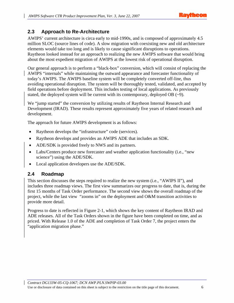
2.4 Roadmap This section discusses the steps required to realize the new system (i.e., “AWIPS II”), and includes three roadmap views. The first view summarizes our progress to date, that is, during the first 15 months of Task Order performance. The second view shows the overall roadmap of the project, while the last view “zooms in” on the deployment and O&M transition activities to provide more detail.
Progress to date is reflected in Figure 2-1, which shows the key content of Raytheon IRAD and ADE releases. All of the Task Orders shown in the figure have been completed on time, and as priced. With Release 1.0 of the ADE and completion of Task Order 7, the project enters the “application migration phase.”
AWIPS Software CTR Product Improvement Plan, Ver. 3, June 22, 2007
Contract DG133W-05-CQ-1067; DCN AWP.PLN.SWPIP-03.00 Use or disclosure of data contained on this sheet is subject to the restriction on the title page of this document. 7
TO 3 TO 4 TO 5 TO 6Raytheon IRAD
6/15/071/4/071/1/06 6/15/06
TO 7Detailed Application Migration Planning
App Migration6/15/096/15/08
TO 10
TO 4 TO 5 TO 6
TO 8
1/1/086/15/07
TO 7
TO 9 TO 11
TO 12
TO 13
TO 4
TO 4
TO 12
TO 13
1/1/08
Release 0.01rst Delivered Code• CM / Deploy Pattern• SOA Templates• Data Plug-ins• Sub / notification• mEngine Scripting• CAVE
Tech. Reference Arch.• SOA Service Framework• Plug-in framework• Micro Engine• Core Base of Services• Core Patterns• Initial Open Source Project
Integration
Release 0.2• Server Execution
Structure• Remote Admin• Legacy Adapters• Alerting Pattern• SOA Services +• CAVE++
Release 0.1• Regression
Test Environ.• CAVE +• mEngine +• Remote Data
Access (XML)• Dissemination
Release 1.0• Localization Pattern
• Server• CAVE
• Stress Testing• Code Hardening• Installation
Simplification
+Ingest Data+Index Data +Store Data+Transform +Auto Build
+Request
+Subscribe +Collaborate
<<Technical Reference Architecture>>Services
<<Technical Reference Architecture>>SOA System Services Data Types
TransformsScripts
+domain libraries+mapping libraries
<<Visualization Framework>>CAVE
Vis Plugin 1+core plug-ins+ libraries
Vis Plugin 2Vis Plugin n
MetaData
Data
+Ingest Data+Index Data +Store Data+Transform +Auto Build
+Request
+Subscribe +Collaborate
<<Technical Reference Architecture>>Services
<<Technical Reference Architecture>>SOA System Services Data Types
TransformsScripts
+domain libraries+mapping libraries
<<Visualization Framework>>CAVE
Vis Plugin 1+core plug-ins+ libraries
Vis Plugin 2Vis Plugin n
MetaData
Data All execution on workstation Add Server Execution
TO 3 TO 4 TO 5 TO 6Raytheon IRAD
6/15/071/4/071/1/06 6/15/06 6/15/071/4/071/1/06 6/15/06
TO 7Detailed Application Migration Planning
App MigrationApp Migration6/15/096/15/08
TO 10
TO 4 TO 5 TO 6
TO 8
1/1/086/15/07
TO 7
TO 9 TO 11
TO 12
TO 13
TO 4
TO 4
TO 12
TO 13
1/1/08
Release 0.01rst Delivered Code• CM / Deploy Pattern• SOA Templates• Data Plug-ins• Sub / notification• mEngine Scripting• CAVE
Tech. Reference Arch.• SOA Service Framework• Plug-in framework• Micro Engine• Core Base of Services• Core Patterns• Initial Open Source Project
Integration
Release 0.2• Server Execution
Structure• Remote Admin• Legacy Adapters• Alerting Pattern• SOA Services +• CAVE++
Release 0.1• Regression
Test Environ.• CAVE +• mEngine +• Remote Data
Access (XML)• Dissemination
Release 1.0• Localization Pattern
• Server• CAVE
• Stress Testing• Code Hardening• Installation
Simplification
+Ingest Data+Index Data +Store Data+Transform +Auto Build
+Request
+Subscribe +Collaborate
<<Technical Reference Architecture>>Services
<<Technical Reference Architecture>>SOA System Services Data Types
TransformsScripts
+domain libraries+mapping libraries
<<Visualization Framework>>CAVE
Vis Plugin 1+core plug-ins+ libraries
Vis Plugin 2Vis Plugin n
MetaData
Data
+Ingest Data+Index Data +Store Data+Transform +Auto Build
+Request
+Subscribe +Collaborate
<<Technical Reference Architecture>>Services
<<Technical Reference Architecture>>SOA System Services Data Types
TransformsScripts
+domain libraries+mapping libraries
<<Visualization Framework>>CAVE
Vis Plugin 1+core plug-ins+ libraries
Vis Plugin 2Vis Plugin n
MetaData
Data All execution on workstation Add Server Execution
Figure 2-1. ADE Release Content
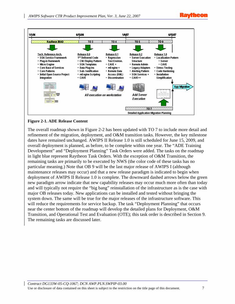
The overall roadmap shown in Figure 2-2 has been updated with TO 7 to include more detail and refinement of the migration, deployment, and O&M transition tasks. However, the key milestone dates have remained unchanged. AWIPS II Release 1.0 is still scheduled for June 15, 2009, and overall deployment is planned, as before, to be complete within one year. The “ADE Training Development” and “Deployment Planning” Task Orders were added. The tasks on the roadmap in light blue represent Raytheon Task Orders. With the exception of O&M Transition, the remaining tasks are primarily to be executed by NWS (the color code of these tasks has no particular meaning.) Note that OB 9 will be the last major release of AWIPS I (although maintenance releases may occur) and that a new release paradigm is indicated to begin when deployment of AWIPS II Release 1.0 is complete. The downward dashed arrows below the green new paradigm arrow indicate that new capability releases may occur much more often than today and will typically not require the “big bang” reinstallation of the infrastructure as is the case with major OB releases today. New applications can be installed and tested without bringing the system down. The same will be true for the major releases of the infrastructure software. This will reduce the requirements for service backup. The task “Deployment Planning” that occurs near the center bottom of the roadmap will develop the detailed plans for Deployment, O&M Transition, and Operational Test and Evaluation (OTE); this task order is described in Section 9. The remaining tasks are discussed later.
AWIPS Software CTR Product Improvement Plan, Ver. 3, June 22, 2007
Contract DG133W-05-CQ-1067; DCN AWP.PLN.SWPIP-03.00 Use or disclosure of data contained on this sheet is subject to the restriction on the title page of this document. 8
Figure 2-2. SW CTR Overall Roadmap
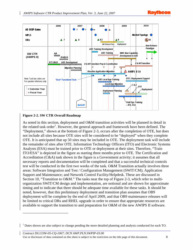
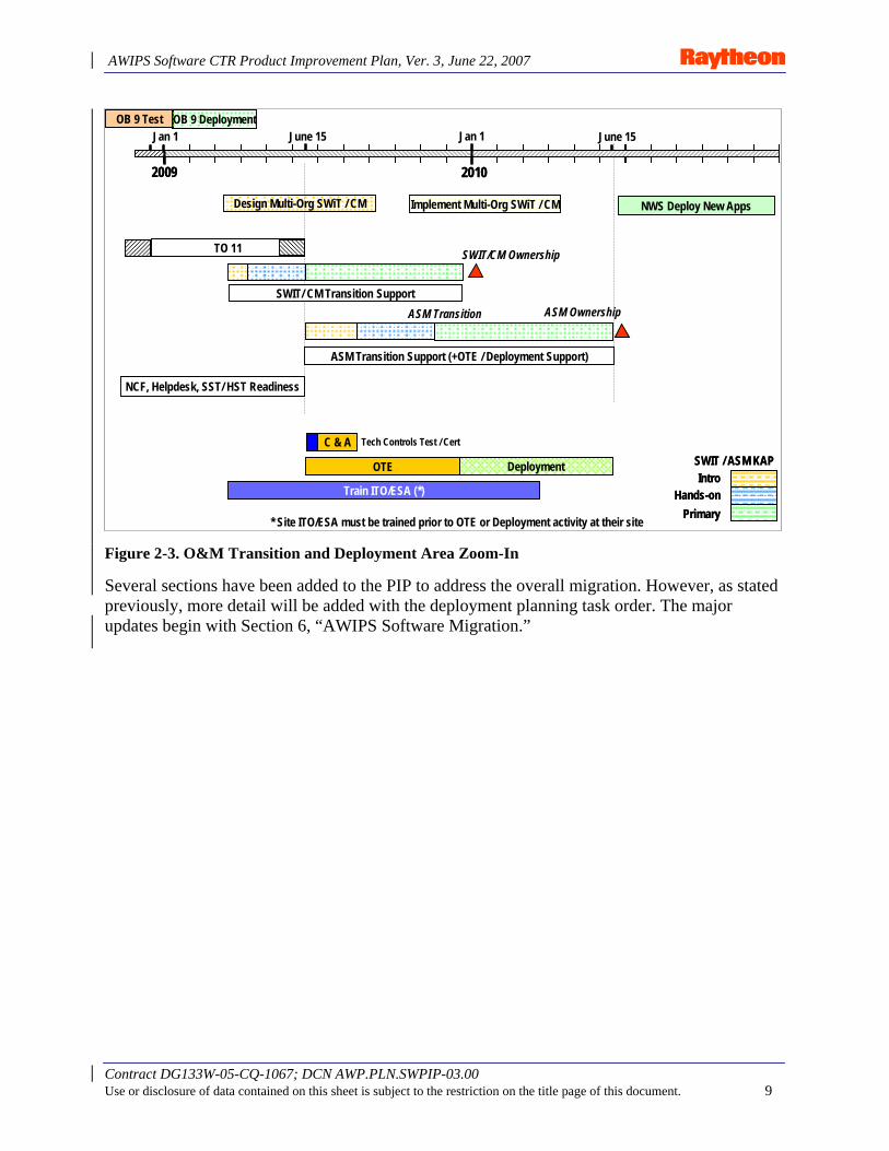
As noted in this section, deployment and O&M transition activities will be planned in detail in the related task order1. However, the general approach and framework have been defined. The “Deployment,” shown at the bottom of Figure 2-3, occurs after the completion of OTE, but does not include all sites because OTE sites will be considered to be “deployed” when they complete OTE. It is anticipated that up 50 sites may be included in OTE. The deployment task will include the remainder of sites after OTE. Information Technology Officers (ITO) and Electronic Systems Analysts (ESA) must be trained prior to OTE or deployment at their sites. Therefore, “Train ITO/ESA” is depicted in the figure as starting three months prior to OTE. The Certification and Accreditation (C&A) task shown in the figure is a Government activity; it assumes that all necessary reports and documentation will be completed and that a successful technical controls test will be conducted in the first two weeks of the task. O&M Transition actually involves three areas: Software Integration and Test / Configuration Management (SWIT/CM); Application Support and Maintenance; and Network Control Facility/Helpdesk. These are discussed in Section 10, “Transition to O&M.” The tasks near the top of Figure 2-3, which refer to multi-organization SWIT/CM design and implementation, are notional and are shown for approximate timing and to indicate that there should be adequate time available for these tasks. It should be noted, however, that this preliminary deployment and transition plan assumes that OB9 deployment will be complete by the end of April 2009, and that OB9 maintenance releases will be limited to critical DRs and RHEL upgrade in order to ensure that appropriate resources are available to support the transition to and preparation for O&M of the new AWIPS II software.
1 Dates shown are also subject to change pending the more detailed planning and analysis conducted for each TO.
2007 2008 201020092006
SW CTR (AWIPS II)
AE OSIP Gates 2 3 4a 4bAE OSIP Gates 2 33 4a4a 4b4b
= Fiscal Year= Calendar Year
MPLS Meshed TopologyMeshed Topology
06/22/0706/22/0706/22/07
OBx 7 8 9 10
PIPAnalysis
Migration Planning
RTS IRAD ADE Development
PIPPIPAnalysisAnalysis
Migration PlanningMigration Planning
RTS IRAD ADE DevelopmentRTS IRAD ADE Development
“User” Functional Tests
Baseline Application Migration
8 8.3
ADE TrainingADE Training
Field Ops Training-- ITO, ESA
DeploymentOTE
C & A
Deployment Planning
Local App Migration
ADE Local App Training
New Release Paradigm
O & M Transition
NWS New Capability Development in ADE
OB 9 Dev & Test Deployment
O & M Transition Prep & Coordination
ADE Training DevelopmentADE Training Development
OTE / Deployment Support
AWIPS II 1.0AWIPS II 1.0
Note: Task bar colors are For speaker reference only
AWIPS Software CTR Product Improvement Plan, Ver. 3, June 22, 2007
Contract DG133W-05-CQ-1067; DCN AWP.PLN.SWPIP-03.00 Use or disclosure of data contained on this sheet is subject to the restriction on the title page of this document. 9
Figure 2-3. O&M Transition and Deployment Area Zoom-In
Several sections have been added to the PIP to address the overall migration. However, as stated previously, more detail will be added with the deployment planning task order. The major updates begin with Section 6, “AWIPS Software Migration.”
June 15Jan 1
2009 2010
Jan 1 June 15June 15Jan 1
2009 2010
Jan 1 June 15
IntroHands-on
Primary
SWIT / ASM KAPIntro
Hands-onPrimary
SWIT / ASM KAP
ASM OwnershipASM Transition
* Site ITO/ESA must be trained prior to OTE or Deployment activity at their site
TO 11TO 11 SWIT/CM Ownership
SWIT/ CM Transition Support
ASM Transition Support (+OTE / Deployment Support)
OB 9 Test OB 9 Deployment
NCF, Helpdesk, SST/ HST Readiness
Implement Multi-Org SWiT / CM NWS Deploy New AppsDesign Multi-Org SWiT / CM
C & A Tech Controls Test / Cert
DeploymentOTE
Train ITO/ESA (*)
AWIPS Software CTR Product Improvement Plan, Ver. 3, June 22, 2007
Contract DG133W-05-CQ-1067; DCN AWP.PLN.SWPIP-03.00 Use or disclosure of data contained on this sheet is subject to the restriction on the title page of this document. 10
3. AWIPS II Architecture
3.1 Introduction Future Weather Service missions require a new AWIPS software architecture. A fundamental driver for the new architecture is the National Weather Service’s desire to utilize Open Source software instead of COTS or proprietary software. Taking this approach, NWS will realize significant savings on license fees and the administrative costs of negotiating and administering software licensing and distribution versus using commercial software (e.g., COTS). Even while realizing these savings in license costs, NWS will benefit from substantial code reuse and the ability to incorporate new Open Source software and enhancements as they become available.
Over the last ten years, Open Source software has become a viable alternative to expensive COTS software. By utilizing Java-based Open Source software, NWS can achieve a significantly lower Total Cost of Ownership (TCO) and improved programmer productivity due to reuse.
This section reviews several aspects of the new AWIPS architecture. In keeping with Raytheon’s current task, which is to provide a plan rather than a design or an implementation, the review has been prepared at a high level. This discussion describes the target state for improving AWIPS software.
The concepts and design constructs presented here will be detailed and implemented under Task Orders 3 through 6, as described in Section 2.5.
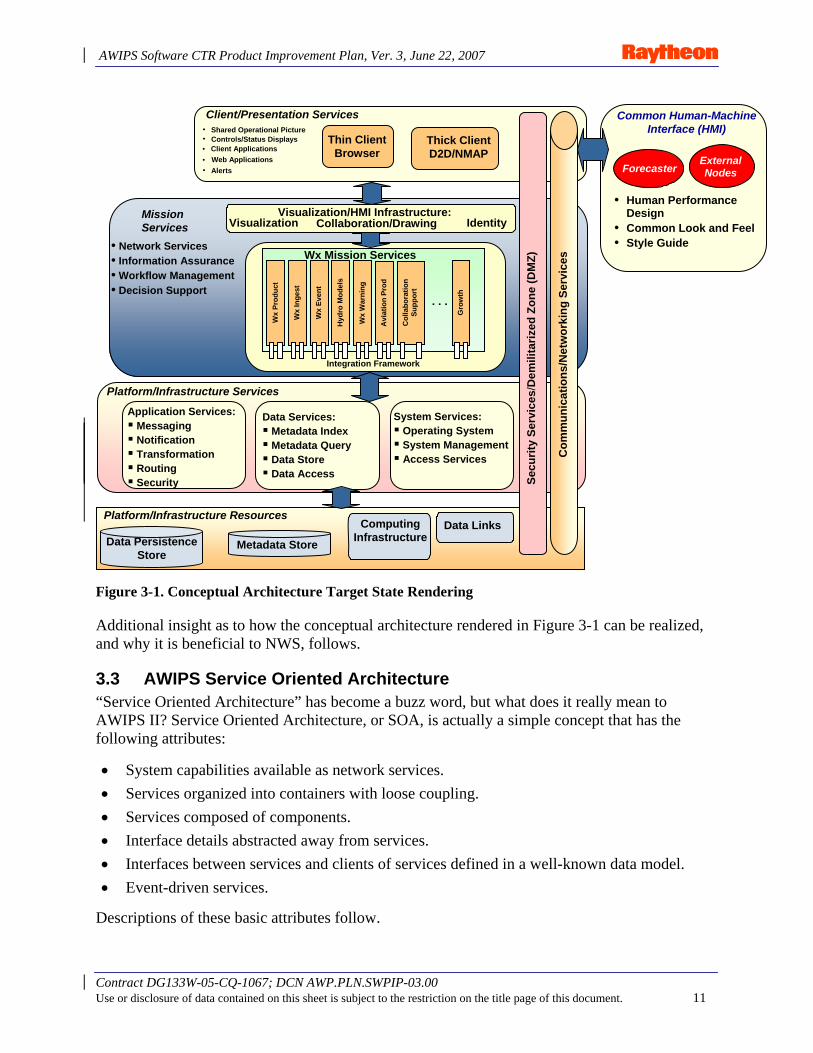
3.2 Conceptual Architecture: Target State Figure 3-1 shows a rendering of the conceptual architecture for AWIPS as a layered model. Generally, higher-level services access services in the next lower layer of the hierarchy. Layers are isolated from one another. The top layers provide the common human-machine interface and presentation services, which access mission services. Mission services access infrastructure services which, in turn, access the platform / infrastructure resources. The layers are interconnected through standard network services, and security services cut across all the layers of the architecture.
AWIPS Software CTR Product Improvement Plan, Ver. 3, June 22, 2007
Contract DG133W-05-CQ-1067; DCN AWP.PLN.SWPIP-03.00 Use or disclosure of data contained on this sheet is subject to the restriction on the title page of this document. 11
Figure 3-1. Conceptual Architecture Target State Rendering
Additional insight as to how the conceptual architecture rendered in Figure 3-1 can be realized, and why it is beneficial to NWS, follows.
3.3 AWIPS Service Oriented Architecture “Service Oriented Architecture” has become a buzz word, but what does it really mean to AWIPS II? Service Oriented Architecture, or SOA, is actually a simple concept that has the following attributes:
• System capabilities available as network services. • Services organized into containers with loose coupling. • Services composed of components. • Interface details abstracted away from services. • Interfaces between services and clients of services defined in a well-known data model. • Event-driven services.
Descriptions of these basic attributes follow.
Forecaster
Common Human-Machine Interface (HMI)
• Client Applications •
Integration Framework
ComputingInfrastructure
Web Applications
Visualization/HMI Infrastructure: Visualization Collaboration/Drawing Identity
Wx
Inge
st
Wx
Even
t
Wx
Prod
uct
Hyd
ro M
odel
s
Wx
War
ning
Avi
atio
n Pr
od
Col
labo
ratio
n Su
ppor
t
Gro
wth
Wx Mission Services
Alerts •
Controls/Status Displays • Shared Operational Picture •
. . .
Thick ClientD2D/NMAP
Thin ClientBrowser
• Human Performance Design
• Common Look and Feel• Style Guide
Client/Presentation Services
Platform/Infrastructure Resources
Mission Services
Platform/Infrastructure Services
Com
mun
icat
ions
/Net
wor
king
Ser
vice
s
Secu
rity
Serv
ices
/Dem
ilita
rized
Zon
e (D
MZ)
Data Links
ExternalNodes
Metadata Store Data Persistence Store
• Network Services • Information Assurance • Workflow Management • Decision Support
System Services: Operating System System Management Access Services
Data Services: Metadata Index Metadata Query Data Store Data Access
Application Services: Messaging Notification Transformation Routing Security

AWIPS Software CTR Product Improvement Plan, Ver. 3, June 22, 2007
Contract DG133W-05-CQ-1067; DCN AWP.PLN.SWPIP-03.00 Use or disclosure of data contained on this sheet is subject to the restriction on the title page of this document. 12
System Capabilities Available as Network Services. Figure 3-2 shows the fundamental idea, and illustrates how the AWIPS II architecture can support enhanced service backup, inter-site coordination, and various thin client and data sharing scenarios.
Network transport protocols [jms|http|https|soap|ftp|tcp|…]
Thin Client
<<SOA Service>>AWIPS Service
Service Container
NAS Data Storage
<<SOA Service>>AWIPS Service
Service Container
AWIPS Site 1
<<SOA Service>>AWIPS Service
Service Container
NAS Data Storage
<<SOA Service>>AWIPS Service
Service Container
AWIPS Site 2
AWIPS Sites n…
Thick Client
Network transport protocols [jms|http|https|soap|ftp|tcp|…]
Thin Client
<<SOA Service>>AWIPS Service
<<SOA Service>>AWIPS Service
<<SOA Service>>AWIPS Service
Service Container
NAS Data Storage
<<SOA Service>>AWIPS Service
<<SOA Service>>AWIPS Service
<<SOA Service>>AWIPS Service
Service Container
AWIPS Site 1
<<SOA Service>>AWIPS Service
<<SOA Service>>AWIPS Service
<<SOA Service>>AWIPS Service
Service Container
NAS Data Storage
<<SOA Service>>AWIPS Service
<<SOA Service>>AWIPS Service
<<SOA Service>>AWIPS Service
Service Container
AWIPS Site 2
AWIPS Sites n…
Thick Client
Figure 3-2. System Capabilities Available as Network Services
End users access services via either a Thick Client or a Thin Client. The clients access services via network transport protocols. In other words, the system capabilities are available as network services. However, the “network transport” may be implemented on a single workstation or across a distributed environment. Either client can access any AWIPS site by simply setting the address similar to a URL. This will support an improved service backup, inter-site coordination, and data sharing services.
The Thin Client has less functionality than the Thick Client, but it can also access multiple sites, and it will fill the needs of Incident Meteorologists (IMET) and Weather Service Offices (WSO) that are being addressed by FX-Net today.
Note the line connecting the NAS data storage to the Thick Client. This indicates that large data sets can be accessed directly to meet performance requirements.
The current AWIPS Wide Area Network (WAN) places limits on multi-site scenarios. However, the MPLS WAN has the potential to enable this scenario when fully meshed (point to point) and with bandwidth improvements. Data distribution and storage approaches over the entire system can improve the technical and cost performance of the system. Service backup for GFE forecasts could be improved with file distribution and update methods (delta transmission and update).
AWIPS Software CTR Product Improvement Plan, Ver. 3, June 22, 2007
Contract DG133W-05-CQ-1067; DCN AWP.PLN.SWPIP-03.00 Use or disclosure of data contained on this sheet is subject to the restriction on the title page of this document. 13
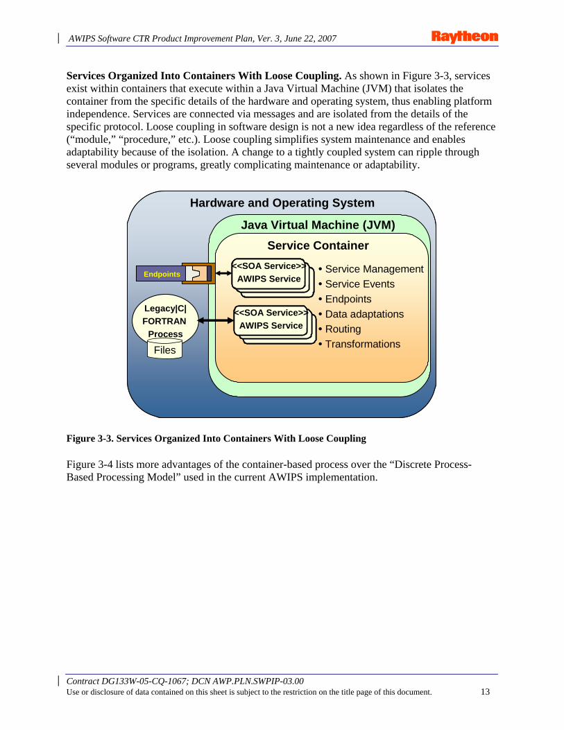
Services Organized Into Containers With Loose Coupling. As shown in Figure 3-3, services exist within containers that execute within a Java Virtual Machine (JVM) that isolates the container from the specific details of the hardware and operating system, thus enabling platform independence. Services are connected via messages and are isolated from the details of the specific protocol. Loose coupling in software design is not a new idea regardless of the reference (“module,” “procedure,” etc.). Loose coupling simplifies system maintenance and enables adaptability because of the isolation. A change to a tightly coupled system can ripple through several modules or programs, greatly complicating maintenance or adaptability.
Figure 3-3. Services Organized Into Containers With Loose Coupling
Figure 3-4 lists more advantages of the container-based process over the “Discrete Process-Based Processing Model” used in the current AWIPS implementation.
<<SOA Service>>AWIPS Service
Service Container
<<SOA Service>>AWIPS Service
Java Virtual Machine (JVM)
Hardware and Operating System
Legacy|C|FORTRAN
Process
Files
Endpoints • Service Management• Service Events• Endpoints• Data adaptations• Routing• Transformations
<<SOA Service>>AWIPS Service
<<SOA Service>>AWIPS Service
<<SOA Service>>AWIPS Service
Service Container
<<SOA Service>>AWIPS Service
<<SOA Service>>AWIPS Service
<<SOA Service>>AWIPS Service
Java Virtual Machine (JVM)
Hardware and Operating System
Legacy|C|FORTRAN
Process
Files
EndpointsEndpoints • Service Management• Service Events• Endpoints• Data adaptations• Routing• Transformations
AWIPS Software CTR Product Improvement Plan, Ver. 3, June 22, 2007
Contract DG133W-05-CQ-1067; DCN AWP.PLN.SWPIP-03.00 Use or disclosure of data contained on this sheet is subject to the restriction on the title page of this document. 14
Figure 3-4. Container-Based Processing
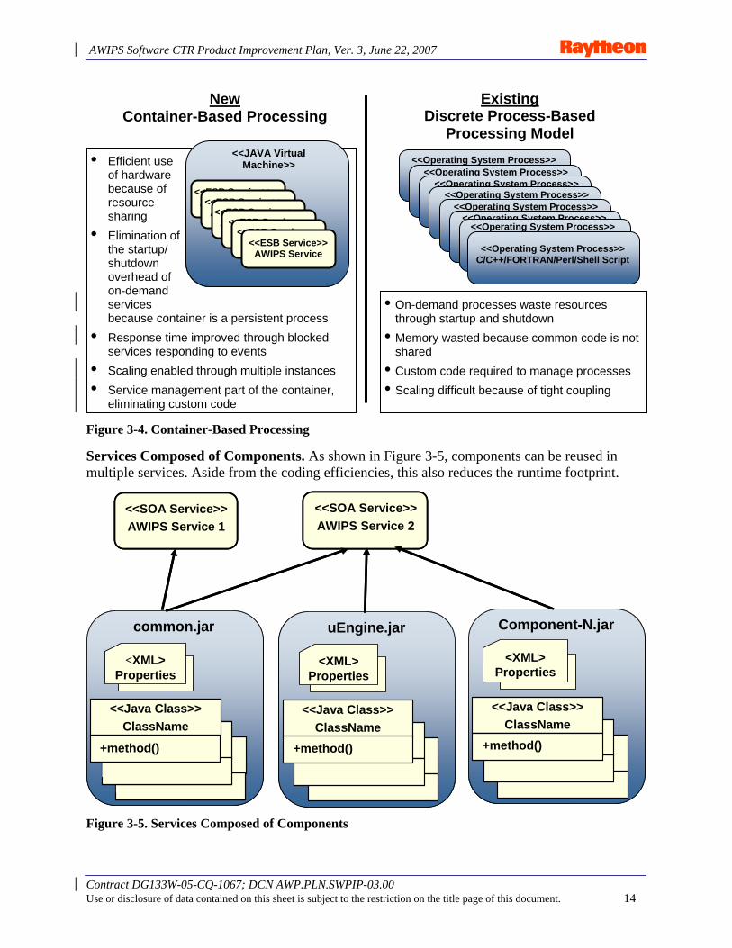
Services Composed of Components. As shown in Figure 3-5, components can be reused in multiple services. Aside from the coding efficiencies, this also reduces the runtime footprint.
<<SOA Service>>AWIPS Service 2
<<Java Class>>ClassName
+method()
<XML>Properties
common.jar
<<Java Class>>ClassName
+method()
<XML>Properties
uEngine.jar
<<Java Class>>ClassName
+method()
<XML>Properties
Component-N.jar
<<SOA Service>>AWIPS Service 1
<<SOA Service>>AWIPS Service 2<<SOA Service>>AWIPS Service 2
<<Java Class>>ClassName
+method()
<XML>Properties
common.jar
<<Java Class>>ClassName
+method()
<XML>Properties
uEngine.jar
<<Java Class>>ClassName
+method()
<XML>Properties
Component-N.jar
<<SOA Service>>AWIPS Service 1<<SOA Service>>AWIPS Service 1
Figure 3-5. Services Composed of Components
New Container-Based Processing
Existing Discrete Process-Based
Processing Model
• Efficient use of hardware because of resource sharing
• Elimination of the startup/ shutdown overhead of on-demand services because container is a persistent process
• Response time improved through blocked services responding to events
• Scaling enabled through multiple instances • Service management part of the container,
eliminating custom code
• On-demand processes waste resources through startup and shutdown
• Memory wasted because common code is not shared
• Custom code required to manage processes • Scaling difficult because of tight coupling
<<ESB Service>> AWIPS Service
<<JAVA Virtual Machine>>
<<ESB Service>> AWIPS Service <<ESB Service>>
AWIPS Service <<ESB Service>> AWIPS Service<<ESB Service>>
AWIPS Service<<ESB Service>> AWIPS Service
<<Operating System Process>> C/C++/Fortran/Perl/Shell Script <<Operating System Process>>
C/C++/Fortran/Perl/Shell Script <<Operating System Process>> C/C++/Fortran/Perl/Shell Script <<Operating System Process>>
C/C++/Fortran/Perl/Shell Script <<Operating System Process>>C/C++/Fortran/Perl/Shell
Script<<Operating System Process>> C/C++/Fortran/Perl/Shell Script <<Operating System Process>>
<<Operating System Process>> C/C++/FORTRAN/Perl/Shell Script
AWIPS Software CTR Product Improvement Plan, Ver. 3, June 22, 2007
Contract DG133W-05-CQ-1067; DCN AWP.PLN.SWPIP-03.00 Use or disclosure of data contained on this sheet is subject to the restriction on the title page of this document. 15
The common practice 10-15 years ago was for each application to contain many core functions that today are available through common services. Being constructed “from the ground up” not only costs more, but it also complicates maintenance and creates “stovepipes.” Modern practice is to use “enterprise” services that are “common” to all services of the enterprise, which in this case is NWS. The extended enterprise would include NOAA and other Government agencies.
Past practices were known to be problematic in the big picture; however, the state of the technology (languages, networking, etc.) did not support the “enterprise” approach of common services. It is currently unknown what proportion of the 4.5 million lines of code is dedicated to services that can be made common today.
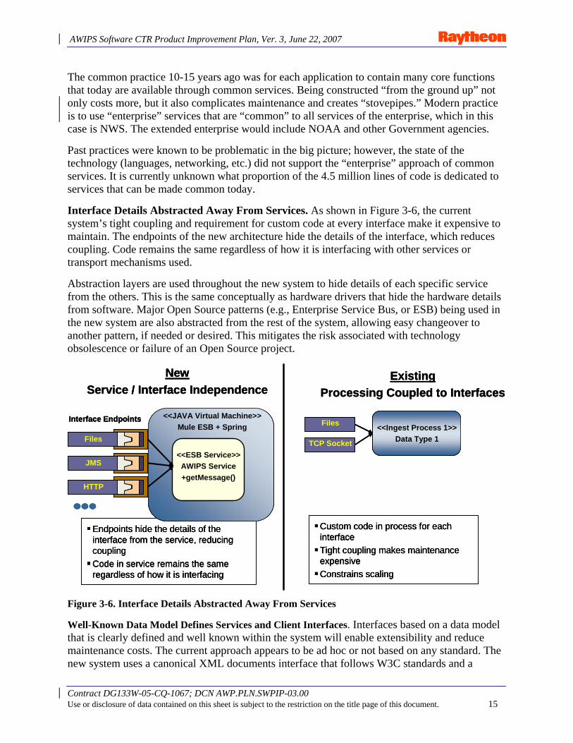
Interface Details Abstracted Away From Services. As shown in Figure 3-6, the current system’s tight coupling and requirement for custom code at every interface make it expensive to maintain. The endpoints of the new architecture hide the details of the interface, which reduces coupling. Code remains the same regardless of how it is interfacing with other services or transport mechanisms used.
Abstraction layers are used throughout the new system to hide details of each specific service from the others. This is the same conceptually as hardware drivers that hide the hardware details from software. Major Open Source patterns (e.g., Enterprise Service Bus, or ESB) being used in the new system are also abstracted from the rest of the system, allowing easy changeover to another pattern, if needed or desired. This mitigates the risk associated with technology obsolescence or failure of an Open Source project.
NewService / Interface Independence
ExistingProcessing Coupled to Interfaces
Endpoints hide the details of the interface from the service, reducing couplingCode in service remains the same regardless of how it is interfacing
Custom code in process for each interfaceTight coupling makes maintenance expensiveConstrains scaling
<<ESB Service>>AWIPS Service+getMessage()
<<JAVA Virtual Machine>>Mule ESB + Spring
Files
JMS
HTTP
Interface Endpoints<<Ingest Process 1>>
Data Type 1
Files
TCP Socket
<<Ingest Process 1>>Data Type 1
Files
TCP Socket
Figure 3-6. Interface Details Abstracted Away From Services
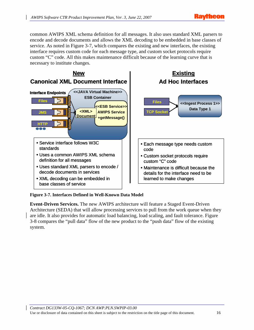
Well-Known Data Model Defines Services and Client Interfaces. Interfaces based on a data model that is clearly defined and well known within the system will enable extensibility and reduce maintenance costs. The current approach appears to be ad hoc or not based on any standard. The new system uses a canonical XML documents interface that follows W3C standards and a
AWIPS Software CTR Product Improvement Plan, Ver. 3, June 22, 2007
Contract DG133W-05-CQ-1067; DCN AWP.PLN.SWPIP-03.00 Use or disclosure of data contained on this sheet is subject to the restriction on the title page of this document. 16
common AWIPS XML schema definition for all messages. It also uses standard XML parsers to encode and decode documents and allows the XML decoding to be embedded in base classes of service. As noted in Figure 3-7, which compares the existing and new interfaces, the existing interface requires custom code for each message type, and custom socket protocols require custom “C” code. All this makes maintenance difficult because of the learning curve that is necessary to institute changes.
NewCanonical XML Document Interface
ExistingAd Hoc Interfaces
• Service interface follows W3C standards
• Uses a common AWIPS XML schema definition for all messages
• Uses standard XML parsers to encode / decode documents in services
• XML decoding can be embedded in base classes of service
• Each message type needs custom code
• Custom socket protocols require custom “C” code
• Maintenance is difficult because the details for the interface need to be learned to make changes
<<ESB Service>>AWIPS Service+getMessage()
<<JAVA Virtual Machine>>ESB Container
Files
JMS
HTTP
Interface Endpoints
<XML>Document
AdaptersA
dapters Adapters
<<Ingest Process 1>>Data Type 1
Files
TCP Socket
NewCanonical XML Document Interface
ExistingAd Hoc Interfaces
• Service interface follows W3C standards
• Uses a common AWIPS XML schema definition for all messages
• Uses standard XML parsers to encode / decode documents in services
• XML decoding can be embedded in base classes of service
• Each message type needs custom code
• Custom socket protocols require custom “C” code
• Maintenance is difficult because the details for the interface need to be learned to make changes
<<ESB Service>>AWIPS Service+getMessage()
<<JAVA Virtual Machine>>ESB Container
Files
JMS
HTTP
Interface Endpoints
<XML>Document
AdaptersA
dapters Adapters
<<ESB Service>>AWIPS Service+getMessage()
<<ESB Service>>AWIPS Service+getMessage()
<<JAVA Virtual Machine>>ESB Container
Files
JMS
HTTP
Interface Endpoints
<XML>Document
AdaptersA
dapters Adapters
<<Ingest Process 1>>Data Type 1
Files
TCP Socket
<<Ingest Process 1>>Data Type 1
Files
TCP Socket
Figure 3-7. Interfaces Defined in Well-Known Data Model
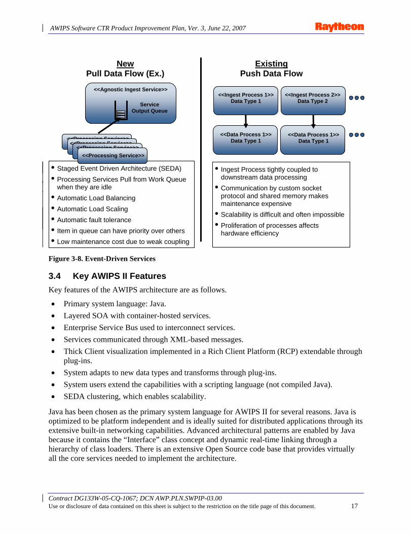
Event-Driven Services. The new AWIPS architecture will feature a Staged Event-Driven Architecture (SEDA) that will allow processing services to pull from the work queue when they are idle. It also provides for automatic load balancing, load scaling, and fault tolerance. Figure 3-8 compares the “pull data” flow of the new product to the “push data” flow of the existing system.
AWIPS Software CTR Product Improvement Plan, Ver. 3, June 22, 2007
Contract DG133W-05-CQ-1067; DCN AWP.PLN.SWPIP-03.00 Use or disclosure of data contained on this sheet is subject to the restriction on the title page of this document. 17
Figure 3-8. Event-Driven Services
3.4 Key AWIPS II Features Key features of the AWIPS architecture are as follows.
• Primary system language: Java. • Layered SOA with container-hosted services. • Enterprise Service Bus used to interconnect services. • Services communicated through XML-based messages. • Thick Client visualization implemented in a Rich Client Platform (RCP) extendable through
plug-ins. • System adapts to new data types and transforms through plug-ins. • System users extend the capabilities with a scripting language (not compiled Java). • SEDA clustering, which enables scalability.
Java has been chosen as the primary system language for AWIPS II for several reasons. Java is optimized to be platform independent and is ideally suited for distributed applications through its extensive built-in networking capabilities. Advanced architectural patterns are enabled by Java because it contains the “Interface” class concept and dynamic real-time linking through a hierarchy of class loaders. There is an extensive Open Source code base that provides virtually all the core services needed to implement the architecture.
New Pull Data Flow (Ex.)
Existing Push Data Flow
<<Ingest Process 1>> Data Type 1
• Staged Event Driven Architecture (SEDA) • Processing Services Pull from Work Queue
when they are idle • Automatic Load Balancing • Automatic Load Scaling • Automatic fault tolerance • Item in queue can have priority over others • Low maintenance cost due to weak coupling
• Ingest Process tightly coupled to downstream data processing
• Communication by custom socket protocol and shared memory makes maintenance expensive
• Scalability is difficult and often impossible • Proliferation of processes affects
hardware efficiency
<<Agnostic Ingest Service>>
Service Output Queue
<<Processing Service>> <<Processing Service>>
<<Processing Service>> <<Processing Service>>
<<Ingest Process 2>> Data Type 2
<<Data Process 1>> Data Type 1
<<Data Process 1>> Data Type 1
AWIPS Software CTR Product Improvement Plan, Ver. 3, June 22, 2007
Contract DG133W-05-CQ-1067; DCN AWP.PLN.SWPIP-03.00 Use or disclosure of data contained on this sheet is subject to the restriction on the title page of this document. 18
Java offers many more advantages, including: • Platform independence via JVM. • Lower development cost through:
− Language efficiency. − Code reuse through object-oriented concepts. − Large body of available open source patterns. − Extensive Java Class libraries, which reduces coding effort. − Garbage collection, which simplifies coding and increases reliability.
• Improved performance through threading and event-driven design patterns. • Java Just-in-Time optimization, which eliminates speed advantage of compiled languages. • Largest population of programmers today.
– University graduates. • No competing language on the horizon.
− Historically, there is a 10-year cycle for new language to become widespread.
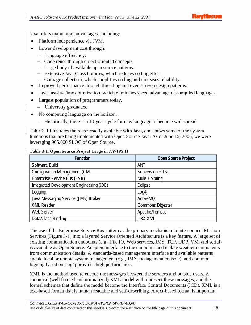
Table 3-1 illustrates the reuse readily available with Java, and shows some of the system functions that are being implemented with Open Source Java. As of June 15, 2006, we were leveraging 965,000 SLOC of Open Source.
Table 3-1. Open Source Project Usage in AWIPS II Function Open Source Project
Software Build ANT Configuration Management (CM) Subversion + Trac Enterprise Service Bus (ESB) Mule + Spring Integrated Development Engineering (IDE) Eclipse Logging Log4j Java Messaging Service (JMS) Broker ActiveMQ XML Reader Commons Digester Web Server Apache/Tomcat Data/Class Binding JiBX XML
The use of the Enterprise Service Bus pattern as the primary mechanism to interconnect Mission Services (Figure 3-1) into a layered Service Oriented Architecture is a key feature. A large set of existing communication endpoints (e.g., File IO, Web services, JMS, TCP, UDP, VM, and serial) is available as Open Source. Adapters interface to the endpoints and isolate weather components from communication details. A standards-based management interface and available patterns enable local or remote system management (e.g., JMX management console), and common logging based on Log4j provides high performance.
XML is the method used to encode the messages between the services and outside users. A canonical (well formed and normalized) XML model will represent these messages, and the formal schemas that define the model become the Interface Control Documents (ICD). XML is a text-based format that is human readable and self-describing. A text-based format is important
AWIPS Software CTR Product Improvement Plan, Ver. 3, June 22, 2007
Contract DG133W-05-CQ-1067; DCN AWP.PLN.SWPIP-03.00 Use or disclosure of data contained on this sheet is subject to the restriction on the title page of this document. 19
for eliminating the platform differences of binary data that inhibit platform independence. Tool and parser availability is another benefit of using XML.
A plug-in approach will enable rapid inclusion of new data types and transforms. The implementation code for all data types will be packaged in dynamic deployable plug-ins that follow a precisely defined pattern. This is an advanced enterprise pattern that ensures system adaptability to new data categories and flexibility. The plug-in pattern will be applied at two levels within the architecture. The first is at the data ingest, storage, decoding, and transformation levels of the data processing. Second, plug-ins are a basic part of the visualization framework. These plug-ins can be hot deployable and delivered via network. The decision to enable this hot plug-in deployment capability over the network will be evaluated once all security issues are addressed.
SEDA provides for scalability, automatic load balancing, and seamless “failover.” The development of distributed data caching frameworks and advances in JMS make SEDA practical at the enterprise level.
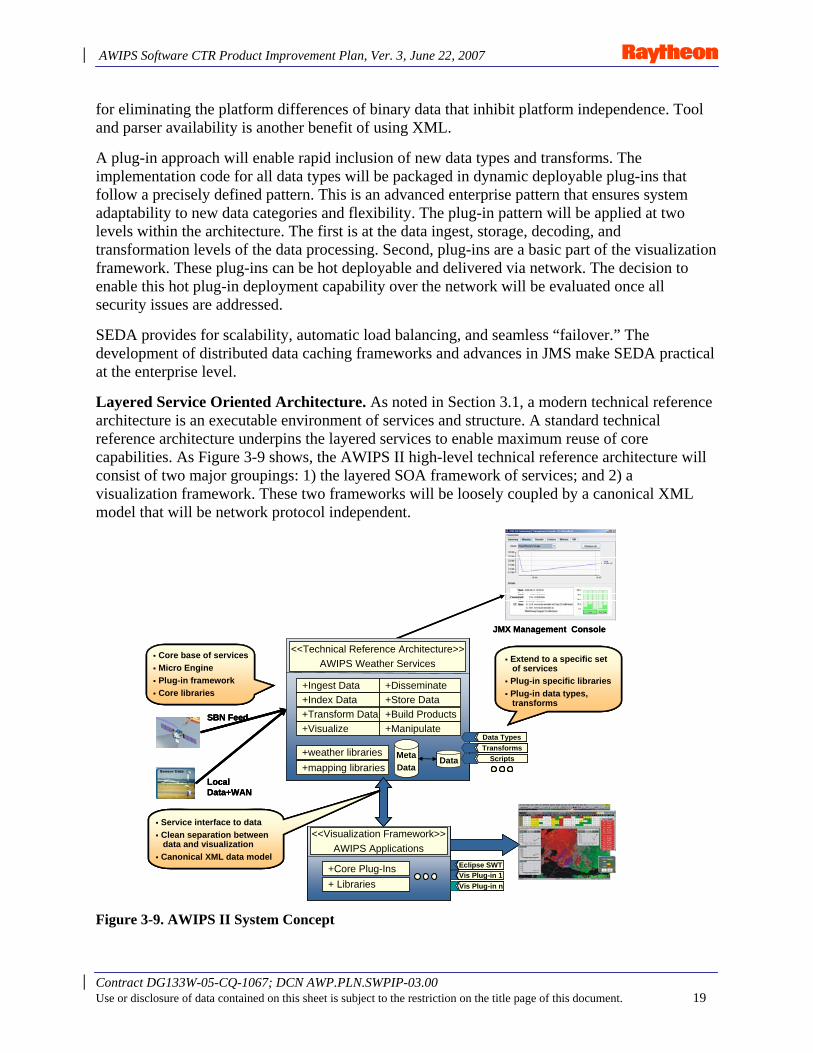
Layered Service Oriented Architecture. As noted in Section 3.1, a modern technical reference architecture is an executable environment of services and structure. A standard technical reference architecture underpins the layered services to enable maximum reuse of core capabilities. As Figure 3-9 shows, the AWIPS II high-level technical reference architecture will consist of two major groupings: 1) the layered SOA framework of services; and 2) a visualization framework. These two frameworks will be loosely coupled by a canonical XML model that will be network protocol independent.
Figure 3-9. AWIPS II System Concept
+Ingest Data+Index Data +Store Data+Transform Data +Build Products
+Disseminate
+Visualize +Manipulate
<<Technical Reference Architecture>>AWIPS Weather Services
Data TypesTransforms
Scripts+weather libraries+mapping libraries
Core base of servicesMicro Engine Plug-in frameworkCore libraries
Extend to a specific set of services Plug-in specific librariesPlug-in data types, transforms
<<Visualization Framework>>AWIPS Applications
Eclipse SWT+Core Plug-Ins+ Libraries
Vis Plug-in 1Vis Plug-in n
Service interface to dataClean separation between data and visualizationCanonical XML data model
SBN Feed
Local Data+WAN
MetaData
Data
JMX Management Console
+Ingest Data+Index Data +Store Data+Transform Data +Build Products
+Disseminate
+Visualize +Manipulate
<<Technical Reference Architecture>>AWIPS Weather Services
Data TypesTransforms
Scripts+weather libraries+mapping libraries
Core base of servicesMicro Engine Plug-in frameworkCore libraries
Extend to a specific set of services Plug-in specific librariesPlug-in data types, transforms
<<Visualization Framework>>AWIPS Applications
Eclipse SWT+Core Plug-Ins+ Libraries
Vis Plug-in 1Vis Plug-in n
Service interface to dataClean separation between data and visualizationCanonical XML data model
SBN Feed
Local Data+WAN
MetaData
Data
JMX Management Console
AWIPS Software CTR Product Improvement Plan, Ver. 3, June 22, 2007
Contract DG133W-05-CQ-1067; DCN AWP.PLN.SWPIP-03.00 Use or disclosure of data contained on this sheet is subject to the restriction on the title page of this document. 20
Figure 3-9 also shows the JMX management console, which will allow monitoring and management of the software either at the site or remotely at the Network Control Facility (NCF). This technical architecture can adapt to a wide range of CONOPS and deployment options. For example, at the minimal end of scalability, all the services can be hosted in a single execution container along with the visualization on a small laptop. This mode of deployment will support the remote user with limited data needs. At the other scalability extreme, the services can be hosted in sets of execution containers on clusters of server hardware without code modification. Multiprocessor high-end graphics workstations can host the visualization applications with the software, taking full advantage of the extra hardware.
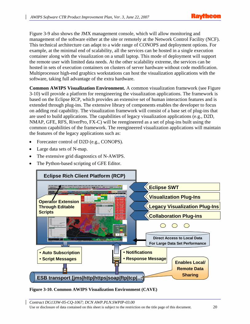
Common AWIPS Visualization Environment. A common visualization framework (see Figure 3-10) will provide a platform for reengineering the visualization applications. The framework is based on the Eclipse RCP, which provides an extensive set of human interaction features and is extended through plug-ins. The extensive library of components enables the developer to focus on adding real capability. The visualization framework will consist of a base set of plug-ins that are used to build applications. The capabilities of legacy visualization applications (e.g., D2D, NMAP, GFE, RFS, RiverPro, FX-C) will be reengineered as a set of plug-ins built using the common capabilities of the framework. The reengineered visualization applications will maintain the features of the legacy applications such as:
• Forecaster control of D2D (e.g., CONOPS). • Large data sets of N-map. • The extensive grid diagnostics of N-AWIPS. • The Python-based scripting of GFE Editor.
Collaboration Plug-ins
Eclipse Rich Client Platform (RCP)
Eclipse SWT
Visualization Plug-Ins
Legacy Visualization Plug-Ins
ESB transport [jms|http|https|soap|ftp|tcp|…]
• Auto Subscription• Script Messages
• Notifications• Response Message
Enables Local/Remote Data
Sharing
Direct Access to Local Data For Large Data Set Performance
Operator Extension Through Editable Scripts
Figure 3-10. Common AWIPS Visualization Environment (CAVE)
AWIPS Software CTR Product Improvement Plan, Ver. 3, June 22, 2007
Contract DG133W-05-CQ-1067; DCN AWP.PLN.SWPIP-03.00 Use or disclosure of data contained on this sheet is subject to the restriction on the title page of this document. 21
The end result will be a platform-independent Thick Client visualization capability – flexible enough to handle the existing weather and hydro needs, with adaptability for changes in CONOPS.
Core framework capabilities beyond the RCP consist of the following:
• Visual rendering that takes advantage of the capabilities of the graphics hardware for performance. This capability uses the standards of OpenGL with a Java API interface and includes, via extensions, the ability to render 2D map-projected data, vertical soundings or cross-sections, and 3D data sets such as radar. Vector, raster, and ASCII data will be supported.
• Quad-Tree tiling at both the disk and memory level maximizes performance and allows rendering of large data sets.
• Automatic data subscriptions and notifications, which enable auto updating display. • Common event handling for user interactions with displayed data including drawing. • A wide scalability range from lightweight laptops with limited graphics to top-line
multi-headed/multi-CPU workstations. • The core functionality package, which is a set of plug-ins, and new functionality
build upon the existing set. • Local customization, accomplished through configuration and local application
scripts. • Large data sets, which will be accessed locally and directly to enable performance.
Extensibility Enabled by Plug-Ins for Data Types and Transforms. Data type plug-ins (see Figure 3-11) will lower the effort required to add new data types and are the primary architectural pattern for enabling extensibility and flexibility. The plug-in implementations define the details of how the data are ingested, persisted, transformed, and made available to the visualization applications. Plug-ins can also be used to introduce new science by adding new transformation classes. The plug-in capability will be packaged as a component and made available to any SOA service. The set of plug-ins can be tailored for the particular deployment and enable extending the full capability of the system to local data sets such as Mesonets. A developer at a local site can write a new plug-in and test it locally without rebuilding the system. All data types will be defined in plug-ins to maximize system flexibility.
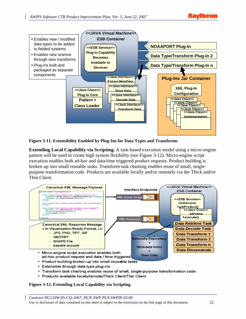
AWIPS Software CTR Product Improvement Plan, Ver. 3, June 22, 2007
Contract DG133W-05-CQ-1067; DCN AWP.PLN.SWPIP-03.00 Use or disclosure of data contained on this sheet is subject to the restriction on the title page of this document. 22
• Enables new / modified data types to be added to fielded systems
• Enables new science through new transforms
• Plug-ins built and packaged as separate components
NOAAPORT Plug-In
Data Type/Transform Plug-In 2
Data Type/Transform Plug-In n
<<ESB Service>>Plug-in Capability
BecomesAvailable to
Services
<<JAVA Virtual Machine>>ESB Container
<<Java Class>>Plug-In CorePattern +
Class Loader
<<Java Interface>>Extract MetaData<<Java Interface>>
Store Data<<Java Interface>>
Decode Data
XML Plug-InConfiguration
<<Java Class>>Implementation<<Java Class>>
Implementation<<Java Class>>Implementation<<Java Class>>
Implementation<<Java Class>>Implementation
Plug-Ins Jar Container
<<Java Interface>>Transform Data
• Enables new / modified data types to be added to fielded systems
• Enables new science through new transforms
• Plug-ins built and packaged as separate components
NOAAPORT Plug-In
Data Type/Transform Plug-In 2
Data Type/Transform Plug-In n
<<ESB Service>>Plug-in Capability
BecomesAvailable to
Services
<<JAVA Virtual Machine>>ESB Container
<<Java Class>>Plug-In CorePattern +
Class Loader
<<Java Interface>>Extract MetaData<<Java Interface>>
Store Data<<Java Interface>>
Store Data<<Java Interface>>
Decode Data<<Java Interface>>
Decode Data
XML Plug-InConfiguration
<<Java Class>>Implementation<<Java Class>>Implementation<<Java Class>>
Implementation<<Java Class>>Implementation<<Java Class>>
Implementation<<Java Class>>Implementation<<Java Class>>
Implementation<<Java Class>>Implementation<<Java Class>>Implementation
Plug-Ins Jar Container
<<Java Interface>>Transform Data
Figure 3-11. Extensibility Enabled by Plug-Ins for Data Types and Transforms
Extending Local Capability via Scripting. A task-based execution model using a micro-engine pattern will be used to create high system flexibility (see Figure 3-12). Micro-engine script execution enables both ad-hoc and data/time triggered product requests. Product building is broken up into small reusable tasks. Transform task chaining enables reuse of small, single-purpose transformation code. Products are available locally and/or remotely via the Thick and/or Thin Client.
Figure 3-12. Extending Local Capability via Scripting
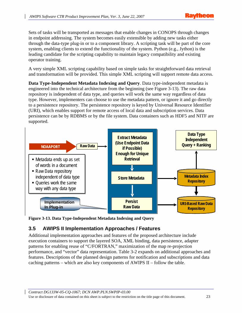
AWIPS Software CTR Product Improvement Plan, Ver. 3, June 22, 2007
Contract DG133W-05-CQ-1067; DCN AWP.PLN.SWPIP-03.00 Use or disclosure of data contained on this sheet is subject to the restriction on the title page of this document. 23
Sets of tasks will be transported as messages that enable changes in CONOPS through changes in endpoint addressing. The system becomes easily extensible by adding new tasks either through the data-type plug-in or to a component library. A scripting task will be part of the core system, enabling clients to extend the functionality of the system. Python (e.g., Jython) is the leading candidate for the scripting capability to maintain legacy compatibility and existing operator training.
A very simple XML scripting capability based on simple tasks for straightforward data retrieval and transformation will be provided. This simple XML scripting will support remote data access.
Data Type-Independent Metadata Indexing and Query. Data type-independent metadata is engineered into the technical architecture from the beginning (see Figure 3-13). The raw data repository is independent of data type, and queries will work the same way regardless of data type. However, implementers can choose to use the metadata pattern, or ignore it and go directly to a persistence repository. The persistence repository is keyed by Universal Resource Identifier (URI), which enables support for remote access of local data and subscription services. Data persistence can be by RDBMS or by the file system. Data containers such as HDF5 and NITF are supported.
ImplementationIn Plug-in
NOAAPORT
Metadata ends up as set of words in a documentRaw Data repository independent of data typeQueries work the same way with any data type
Metadata ends up as set of words in a documentRaw Data repository independent of data typeQueries work the same way with any data type
Raw Data
Extract Metadata(Use Endpoint Data
if Possible)Enough for Unique
Retrieval
Store Metadata
PersistRaw Data
Data TypeIndependent
Query + Ranking
Metadata IndexRepository
URI-Based Raw DataRepository
ImplementationIn Plug-in
NOAAPORT
Metadata ends up as set of words in a documentRaw Data repository independent of data typeQueries work the same way with any data type
Metadata ends up as set of words in a documentRaw Data repository independent of data typeQueries work the same way with any data type
Raw Data
Extract Metadata(Use Endpoint Data
if Possible)Enough for Unique
Retrieval
Extract Metadata(Use Endpoint Data
if Possible)Enough for Unique
Retrieval
Store MetadataStore Metadata
PersistRaw Data
PersistRaw Data
Data TypeIndependent
Query + Ranking
Metadata IndexRepository
URI-Based Raw DataRepository
Figure 3-13. Data Type-Independent Metadata Indexing and Query
3.5 AWIPS II Implementation Approaches / Features Additional implementation approaches and features of the proposed architecture include execution containers to support the layered SOA, XML binding, data persistence, adapter patterns for enabling reuse of “C/FORTRAN,” maximization of the map re-projection performance, and “vector” data representation. Table 3-2 expands on additional approaches and features. Descriptions of the planned design patterns for notification and subscriptions and data caching patterns – which are also key components of AWIPS II – follow the table.
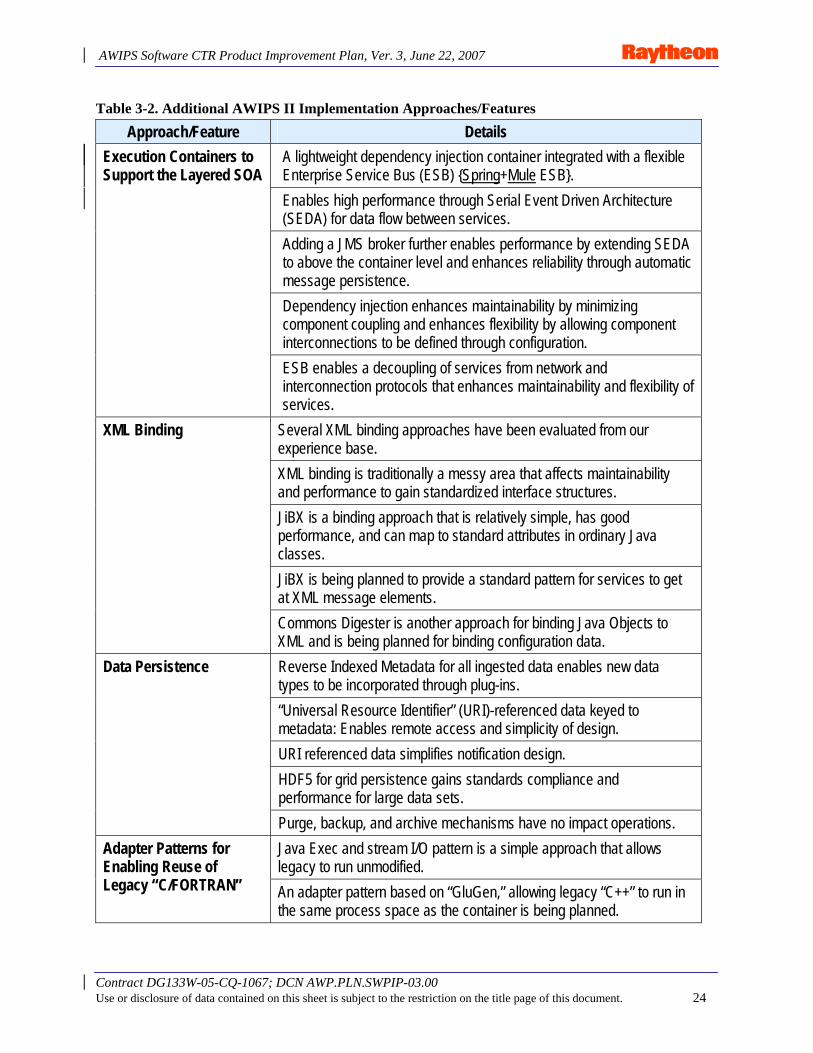
AWIPS Software CTR Product Improvement Plan, Ver. 3, June 22, 2007
Contract DG133W-05-CQ-1067; DCN AWP.PLN.SWPIP-03.00 Use or disclosure of data contained on this sheet is subject to the restriction on the title page of this document. 24
Table 3-2. Additional AWIPS II Implementation Approaches/Features
Approach/Feature Details A lightweight dependency injection container integrated with a flexible Enterprise Service Bus (ESB) {Spring+Mule ESB}. Enables high performance through Serial Event Driven Architecture (SEDA) for data flow between services. Adding a JMS broker further enables performance by extending SEDA to above the container level and enhances reliability through automatic message persistence. Dependency injection enhances maintainability by minimizing component coupling and enhances flexibility by allowing component interconnections to be defined through configuration.
Execution Containers to Support the Layered SOA
ESB enables a decoupling of services from network and interconnection protocols that enhances maintainability and flexibility of services.
Several XML binding approaches have been evaluated from our experience base. XML binding is traditionally a messy area that affects maintainability and performance to gain standardized interface structures. JiBX is a binding approach that is relatively simple, has good performance, and can map to standard attributes in ordinary Java classes. JiBX is being planned to provide a standard pattern for services to get at XML message elements.
XML Binding
Commons Digester is another approach for binding Java Objects to XML and is being planned for binding configuration data. Reverse Indexed Metadata for all ingested data enables new data types to be incorporated through plug-ins. “Universal Resource Identifier” (URI)-referenced data keyed to metadata: Enables remote access and simplicity of design. URI referenced data simplifies notification design. HDF5 for grid persistence gains standards compliance and performance for large data sets.
Data Persistence
Purge, backup, and archive mechanisms have no impact operations. Java Exec and stream I/O pattern is a simple approach that allows legacy to run unmodified.
Adapter Patterns for Enabling Reuse of Legacy “C/FORTRAN” An adapter pattern based on “GluGen,” allowing legacy “C++” to run in
the same process space as the container is being planned.
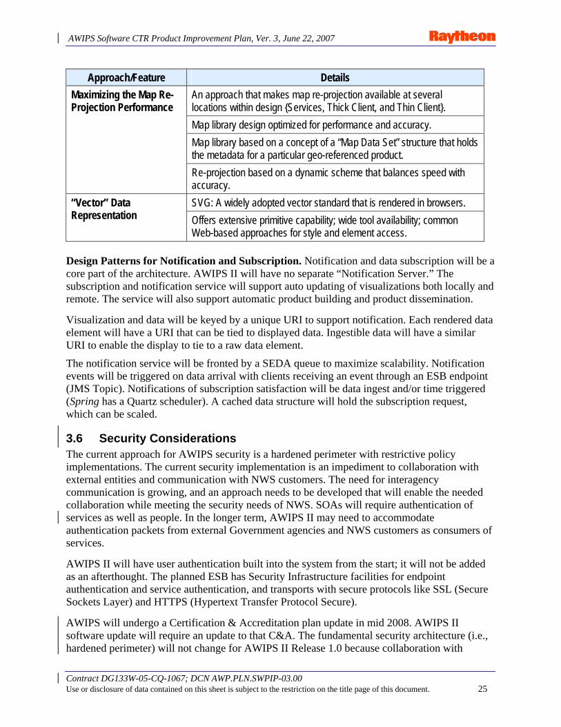
AWIPS Software CTR Product Improvement Plan, Ver. 3, June 22, 2007
Contract DG133W-05-CQ-1067; DCN AWP.PLN.SWPIP-03.00 Use or disclosure of data contained on this sheet is subject to the restriction on the title page of this document. 25
Approach/Feature Details An approach that makes map re-projection available at several locations within design {Services, Thick Client, and Thin Client}. Map library design optimized for performance and accuracy. Map library based on a concept of a “Map Data Set” structure that holds the metadata for a particular geo-referenced product.
Maximizing the Map Re-Projection Performance
Re-projection based on a dynamic scheme that balances speed with accuracy. SVG: A widely adopted vector standard that is rendered in browsers. “Vector” Data
Representation Offers extensive primitive capability; wide tool availability; common Web-based approaches for style and element access.
Design Patterns for Notification and Subscription. Notification and data subscription will be a core part of the architecture. AWIPS II will have no separate “Notification Server.” The subscription and notification service will support auto updating of visualizations both locally and remote. The service will also support automatic product building and product dissemination.
Visualization and data will be keyed by a unique URI to support notification. Each rendered data element will have a URI that can be tied to displayed data. Ingestible data will have a similar URI to enable the display to tie to a raw data element.
The notification service will be fronted by a SEDA queue to maximize scalability. Notification events will be triggered on data arrival with clients receiving an event through an ESB endpoint (JMS Topic). Notifications of subscription satisfaction will be data ingest and/or time triggered (Spring has a Quartz scheduler). A cached data structure will hold the subscription request, which can be scaled.
3.6 Security Considerations The current approach for AWIPS security is a hardened perimeter with restrictive policy implementations. The current security implementation is an impediment to collaboration with external entities and communication with NWS customers. The need for interagency communication is growing, and an approach needs to be developed that will enable the needed collaboration while meeting the security needs of NWS. SOAs will require authentication of services as well as people. In the longer term, AWIPS II may need to accommodate authentication packets from external Government agencies and NWS customers as consumers of services.
AWIPS II will have user authentication built into the system from the start; it will not be added as an afterthought. The planned ESB has Security Infrastructure facilities for endpoint authentication and service authentication, and transports with secure protocols like SSL (Secure Sockets Layer) and HTTPS (Hypertext Transfer Protocol Secure).
AWIPS will undergo a Certification & Accreditation plan update in mid 2008. AWIPS II software update will require an update to that C&A. The fundamental security architecture (i.e., hardened perimeter) will not change for AWIPS II Release 1.0 because collaboration with
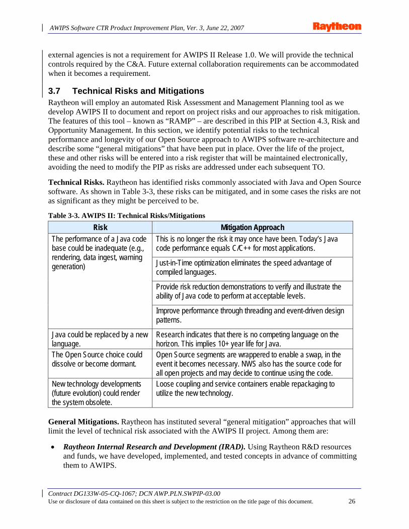
AWIPS Software CTR Product Improvement Plan, Ver. 3, June 22, 2007
Contract DG133W-05-CQ-1067; DCN AWP.PLN.SWPIP-03.00 Use or disclosure of data contained on this sheet is subject to the restriction on the title page of this document. 26
external agencies is not a requirement for AWIPS II Release 1.0. We will provide the technical controls required by the C&A. Future external collaboration requirements can be accommodated when it becomes a requirement.
3.7 Technical Risks and Mitigations Raytheon will employ an automated Risk Assessment and Management Planning tool as we develop AWIPS II to document and report on project risks and our approaches to risk mitigation. The features of this tool – known as “RAMP” – are described in this PIP at Section 4.3, Risk and Opportunity Management. In this section, we identify potential risks to the technical performance and longevity of our Open Source approach to AWIPS software re-architecture and describe some “general mitigations” that have been put in place. Over the life of the project, these and other risks will be entered into a risk register that will be maintained electronically, avoiding the need to modify the PIP as risks are addressed under each subsequent TO.
Technical Risks. Raytheon has identified risks commonly associated with Java and Open Source software. As shown in Table 3-3, these risks can be mitigated, and in some cases the risks are not as significant as they might be perceived to be.
Table 3-3. AWIPS II: Technical Risks/Mitigations
Risk Mitigation Approach This is no longer the risk it may once have been. Today’s Java code performance equals C/C++ for most applications.
Just-in-Time optimization eliminates the speed advantage of compiled languages.
Provide risk reduction demonstrations to verify and illustrate the ability of Java code to perform at acceptable levels.
The performance of a Java code base could be inadequate (e.g., rendering, data ingest, warning generation)
Improve performance through threading and event-driven design patterns.
Java could be replaced by a new language.
Research indicates that there is no competing language on the horizon. This implies 10+ year life for Java.
The Open Source choice could dissolve or become dormant.
Open Source segments are wrappered to enable a swap, in the event it becomes necessary. NWS also has the source code for all open projects and may decide to continue using the code.
New technology developments (future evolution) could render the system obsolete.
Loose coupling and service containers enable repackaging to utilize the new technology.
General Mitigations. Raytheon has instituted several “general mitigation” approaches that will limit the level of technical risk associated with the AWIPS II project. Among them are:
• Raytheon Internal Research and Development (IRAD). Using Raytheon R&D resources and funds, we have developed, implemented, and tested concepts in advance of committing them to AWIPS.
AWIPS Software CTR Product Improvement Plan, Ver. 3, June 22, 2007
Contract DG133W-05-CQ-1067; DCN AWP.PLN.SWPIP-03.00 Use or disclosure of data contained on this sheet is subject to the restriction on the title page of this document. 27
• Risk Reduction Demonstrations. A Risk Reduction Demonstration (RRD) is a technique used to verify the viability of specific implementation approaches for critical system capabilities early in the development cycle. The prototype (i.e., not production hardened) implementations address key functional capabilities and/or system performance. A performance RRD provides an indicator or relative measure of performance rather than an absolute measure. The goal of the RRD is to determine if the approach is likely to produce the required performance. Marginal performance results indicate more investigation is needed. Functional RRDs are typically conducted to prove (or demonstrate) that a particular functionality can be provided. Success is generally more black and white than a performance demonstration in that the function is performed or not. RRDs are performed to address concerns of requirements realization. Raytheon has and will continue to perform functional and performance risk reduction demonstrations as needed. These RRDs will be specified in Task Order Proposals.
• Industry Trends and Development. We will monitor the industry for more Java-based capability in work, and for hardware and networking advancements relevant to AWIPS.
• Existing Algorithms. We will “borrow” from the current system in cases where we determine that the reuse of existing algorithms or the encapsulation of existing code serves to mitigate development risks without compromising future performance. Raytheon and NWS will work together to decide which algorithms to use when different algorithms exist in AWIPS I for the same problem. (e.g., calculate relative humidity). NWS will also review Raytheon data sets used to verify migrated algorithms.
AWIPS Software CTR Product Improvement Plan, Ver. 3, June 22, 2007
Contract DG133W-05-CQ-1067; DCN AWP.PLN.SWPIP-03.00 Use or disclosure of data contained on this sheet is subject to the restriction on the title page of this document. 28
4. Project Management
4.1 Assumptions Raytheon made several key assumptions during development of the original proposal for this effort (see Figure 6-4 of the proposal), and revalidated them during Task Order 1. These assumptions follow.
• This plan assumes reuse of software, both from the current AWIPS system and from other Raytheon weather programs under development.
• The project requires free and open access to NWS personnel at NWS Headquarters, the Regional Headquarters, the development labs, and various WFOs, RFCs, and National Centers on a non-interference basis. This access is required to complete an accurate assessment of the current AWIPS system and identify critical data and work flows.
• Software developers will use existing office workstations and Open Source tools. Software developed on this project will be made available, on a non-proprietary basis, to the National Weather Service and associated development organizations.
• Configuration management and software builds will be performed at the software development team location until the first system is deployed to the field. Development servers will be obtained and installed through the recapitalization of ongoing server upgrade activities.
• The team will require access to all weather data available to operational AWIPS organizations. Raytheon has installed a NOAAPort antenna and receiver at the Omaha office and will use that system to emulate the Satellite Broadcast Network (SBN) data feed. Other data flows into AWIPS will be identified during Task Order 2, and necessary steps will be taken to capture those data for use during development.
• During Task Order 2, interfaces to automated sensors that directly feed the current operational AWIPS systems will be identified. Steps will be taken to emulate those live sensor feeds; they will be identified during Task Order 2.
4.2 Organization Figure 4-1 shows the organizational structure for the SW CTR software re-architecture project. Management controls include programmatic control through the AWIPS Evolution Manager, and strategy and architecture controls via the Chief Systems Architect and Strategy Manager. Various Raytheon functional organizations, including IT support, and process and engineering management, provide additional support to the development activities executed on the project.
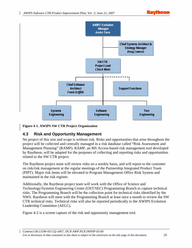
AWIPS Software CTR Product Improvement Plan, Ver. 3, June 22, 2007
Contract DG133W-05-CQ-1067; DCN AWP.PLN.SWPIP-03.00 Use or disclosure of data contained on this sheet is subject to the restriction on the title page of this document. 29
Figure 4-1. AWIPS SW CTR Project Organization
4.3 Risk and Opportunity Management No project of this size and scope is without risk. Risks and opportunities that arise throughout the project will be collected and centrally managed in a risk database called “Risk Assessment and Management Planning” (RAMP). RAMP, an MS Access-based risk management tool developed by Raytheon, will be adapted for the purposes of collecting and reporting risks and opportunities related to the SW CTR project.
The Raytheon project team will review risks on a weekly basis, and will report to the customer on risk/risk management at the regular meetings of the Partnership Integrated Product Team (PIPT). Major risk items will be elevated to Program Management Office Risk System and maintained in the risk register.
Additionally, the Raytheon project team will work with the Office of Science and Technology/Systems Engineering Center (OST/SEC) Programming Branch to capture technical risks. The Programming Branch will be the collection point for technical risks identified by the NWS. Raytheon will meet with the Programming Branch at least once a month to review the SW CTR technical risks. Technical risks will also be reported periodically to the AWIPS Evolution Leadership Committee (AELC).
Figure 4-2 is a screen capture of the risk and opportunity management tool.
Chief SoftwareArchitect
Frank Griffith
Chief SoftwareArchitect
Frank Griffith
Systems EngineeringSystems
EngineeringTest
EngineeringTest
Engineering
SW CTR Project LeadChuck Meier
SW CTR Project LeadChuck Meier
Chief Systems Architect &Strategy Manager
Doug Lawson
Chief Systems Architect &Strategy Manager
Doug Lawson
AWIPS EvolutionManager
Andre Tarro
AWIPS EvolutionManager
Andre Tarro
Support FunctionsSupport Functions
Software EngineeringSoftware
Engineering
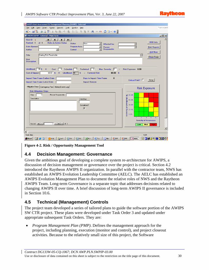
AWIPS Software CTR Product Improvement Plan, Ver. 3, June 22, 2007
Contract DG133W-05-CQ-1067; DCN AWP.PLN.SWPIP-03.00 Use or disclosure of data contained on this sheet is subject to the restriction on the title page of this document. 30
Figure 4-2. Risk / Opportunity Management Tool
4.4 Decision Management: Governance Given the ambitious goal of developing a complete system re-architecture for AWIPS, a discussion of decision management or governance over the project is critical. Section 4.2 introduced the Raytheon AWIPS II organization. In parallel with the contractor team, NWS has established an AWIPS Evolution Leadership Committee (AELC). The AELC has established an AWIPS Evolution Management Plan to document the relative roles of NWS and the Raytheon AWIPS Team. Long-term Governance is a separate topic that addresses decisions related to changing AWIPS II over time. A brief discussion of long-term AWIPS II governance is included in Section 10.6.
4.5 Technical (Management) Controls The project team developed a series of tailored plans to guide the software portion of the AWIPS SW CTR project. These plans were developed under Task Order 3 and updated under appropriate subsequent Task Orders. They are:
• Program Management Plan (PMP). Defines the management approach for the project, including planning, execution (monitor and control), and project closeout activities. Because to the relatively small size of this project, the Software
AWIPS Software CTR Product Improvement Plan, Ver. 3, June 22, 2007
Contract DG133W-05-CQ-1067; DCN AWP.PLN.SWPIP-03.00 Use or disclosure of data contained on this sheet is subject to the restriction on the title page of this document. 31
Development, Configuration Management, Quality Assurance, and System Engineering Management Plans described in this section are included in the PMP.
• Software Development Plan (SDP). Defines the management approach to planning, designing, developing, controlling, and tracking software development across the engineering life cycle of the project. The plan will outline the development activities, the development library, coding standards, and the safety and security of the software development environment.
• Configuration Management Plan (CMP). Provides a detailed description of the tasks associated with managing the configuration of the software during development. The CMP will follow well-defined and documented procedures and processes for developing high-quality software and for managing the project baseline once established.
• Quality Assurance Plan (QAP). Documents the procedures for establishing and maintaining product and process integrity based on both contractual and company requirements. The QAP will detail activities conducted to profile various well-established engineering standards and procedures, tailored for the AWIPS SW CTR project.
• System Engineering Management Plan (SEMP). Documents the system-level requirements and lays out the plan to develop a coherent and consistent AWIPS system across all stakeholder organizations within NWS.
• Additional Technical Controls. Includes routine interaction with the AELC and NWS leadership; Technical Interchange Meetings (TIM) with development organizations; updates to the PIP and software development metrics.
4.6 Integrated Master Plan; Integrated Master Schedule The Integrated Master Plan (IMP) contains a high-level description of the project, including the end-state deliverables of the system and the path (including key milestones) to get to the end state. The IMP does not contain detailed schedules or cost information.
The Integrated Master Schedule (IMS) includes a high-level project schedule and provides a framework for the more detailed Work Breakdown Structure (WBS). The WBS resource loads hours and people against individual tasks. The IMS is maintained and updated as required as each Task Order is added to the program.
4.7 Facilities and Capital Equipment The software project team performs work at Raytheon’s offices in the Scott Technology Center of the Peter-Kiewit Institute on the campus of the University of Nebraska and at Raytheon’s Silver Spring, Maryland facility. Developers will use their standard desktop workstations for software development and testing. The AWIPS program provided the development and database servers through recapitalization of equipment made available through the normal cycle of hardware refresh at the Raytheon test bed facility in Silver Spring, MD. The Raytheon Information Technology (IT) staff provides on-site support for the servers and desktop development environments. Development occurs within the One Raytheon Integrated On-demand Network (ORION).
AWIPS Software CTR Product Improvement Plan, Ver. 3, June 22, 2007
Contract DG133W-05-CQ-1067; DCN AWP.PLN.SWPIP-03.00 Use or disclosure of data contained on this sheet is subject to the restriction on the title page of this document. 32
4.8 Formal Reviews and Reporting The IMS includes milestones to account for formal project reviews at various decision points. At a minimum, these reviews occur near the conclusion of each TO. The AWIPS Evolution Manager and the Chief Systems Architect represent the development team at regularly scheduled AELC meetings. These meetings provide a forum for communicating the status of development activities. Raytheon will also report the status of the project at regularly scheduled partnership IPT meetings.
AWIPS Software CTR Product Improvement Plan, Ver. 3, June 22, 2007
Contract DG133W-05-CQ-1067; DCN AWP.PLN.SWPIP-03.00 Use or disclosure of data contained on this sheet is subject to the restriction on the title page of this document. 33
5. Software Development
5.1 Software Configuration Management Raytheon established a software Configuration Management (CM) environment on the development servers during Task Order 3. The CM tool is Subversion, which is a Java-based variation of the commonly used CVS tool. The development team also uses the Open Source tool Trac for project management and another Open Source tool – Cruise Control – for routine software builds.
5.2 Testing Testing is a continuous process throughout the software development life cycle. The Software Development Plan, developed under TO3, defines objectives, procedures, and schedules for:
• Unit Test – during development. • Integration Test – as components are brought together to form the system. • System Test – at the end of integration and prior to final acceptance testing. • Acceptance Test – final stage of test where NWS will accept the new system.
In addition to formalized testing, developers submit software for formal review in a series of Code Reviews conducted throughout the development phase. The results of those code reviews are documented and added to the software library. Details of the early stages of testing are documented in the SDP developed during TO 3. Later in the development cycle, at the time of system testing, a separate Test Plan (TP) was developed. The TP includes the details of system testing and indicates the timing and location of the System Test. There are also other opportunities throughout the development cycle for users and developers to get an early (hands-on) look at the new system. The details of these opportunities are provided in appropriate TOs and in updates to this PIP document.
5.3 Documentation During project startup, a number of documents were created that guide the software development process. Several of those documents are identified in Section 4.5. In addition to those documents, a set of project instructions was created. These instructions provide the developers with guidelines for completing routine development activities.
“Javadocs” are written on all components and services of the new architecture, and account for the software details of AWIPS II.
Additional “deliverable” documentation is developed under individual TOs as required. TO proposals detail all deliverable documentation associated with that particular TO.
5.4 Standards The AWIPS II software development team will adhere to Sun Java coding standards for Java coding standards, and will follow Raytheon software coding standards for C, C++, and Fortran, if used. The coding standards have been made available to the NWS.
AWIPS Software CTR Product Improvement Plan, Ver. 3, June 22, 2007
Contract DG133W-05-CQ-1067; DCN AWP.PLN.SWPIP-03.00 Use or disclosure of data contained on this sheet is subject to the restriction on the title page of this document. 34
All other technical standards related to the software project or interfaces to other parts of AWIPS Evolution (i.e., hardware and communications) will follow Raytheon standards.
5.5 Tools Raytheon will use appropriate software development tools, including:
• MS Visio Professional – to build the system and software architectural artifacts. • Eclipse – used by software developers both as an Integrated Development Environment
(IDE) and as a Rich Client Platform (RCP) to build client-server applications. • Subversion – a Java-based CM tool similar to CVS. • Trac – an Open Source, project management tool. A more detailed list of tools is included in the SDP developed during TO3.
5.6 Backup and Recovery Raytheon has instituted backup and recovery procedures to protect the development environment. Details of the backup and recovery procedures are documented in the SDP.
5.7 Security (Information Assurance) Raytheon has established physical security measures to protect the development environment from outside intrusion and unapproved access. ORION is a protected Wide Area Network with sufficient security measures in place to protect corporate assets and intellectual property from outside interference. This same high level of security provides the security necessary to protect both the development environment and the software being developed for AWIPS SW CTR.
AWIPS Software CTR Product Improvement Plan, Ver. 3, June 22, 2007
Contract DG133W-05-CQ-1067; DCN AWP.PLN.SWPIP-03.00 Use or disclosure of data contained on this sheet is subject to the restriction on the title page of this document. 35
6. AWIPS Software Migration
6.1 Migration Approach The “black box conversion” mentioned as a fundamental approach to AWIPS II migration means that the current AWIPS “applications” functionality will appear the same to the end-users (e.g., forecaster, hydrologists), but the inner workings of AWIPS that produces the end-user functionality will change.
The conceptual approach to migrating AWIPS to AWIPS II follows. AWIPS II functionality can be divided into two broad categories: end-user and infrastructure. Migrating AWIPS to AWIPS II involves creating the infrastructure functionality that enables the creation and execution of end-user functionality (whatever the end-users see and touch generally manifests in GUIs and hard/softcopy output). When the migration is complete, AWIPS II will be a single environment of end-user and infrastructure functionality. Everything needed to create and execute desired end-user functionality will be present in the environment.
The overall approach to migrating AWIPS to the new AWIPS II architecture is to first design the framework and implement sufficient infrastructure functionality to begin migration, and then migrate end-user functionality while implementing the remainder of the needed infrastructure functionality. We start end-user functionality migration before the infrastructure is complete. Beginning end-user functionality migration with an infrastructure that is incomplete, but sufficient, rather than waiting until the infrastructure is “complete” reduces overall project cycle time and cost. Risk Reduction Demos (RRD), discussed in section 3.7, were employed to manage technical risk. The collection of sufficient infrastructure functionality to begin end-user functionality migration is ADE 1.0.
During Task Order 7, “Migration Planning,” the existing AWIPS I code base was analyzed in detail and fundamental migration methods were examined for different applications. Options considered were: “delete”, or don’t migrate obviated code or applications to be retired; encapsulate, or interface, legacy code (e.g., RFP, LAPS); and re-engineer and re-implement application functionality. Most code fell into the last category.
The existing code was decomposed into discrete functions. During this process, AWIPS I functional redundancy was identified. The redundant functions will be re-engineered into a single function (or infrastructure capability) and re-implemented using the ADE capabilities in AWIPS II. This will eliminate the redundant code and greatly reduce the size of the code base. The discrete functions will be “reassembled” to replicate AWIPS I forecaster functionality. Because this approach does not convert one application at a time, a means other than “checking off” the applications was needed to ensure everything is migrated. To meet this need, a “capabilities matrix” was created that maps the discrete re-engineered functions to the AWIPS I CSCIs (computer software configuration items). The Capabilities Matrix also groups the discrete functions into the four software migration task orders (TO8, 9, 10, 11).3 The functions are scheduled for migration within the task orders to maximize integration opportunities (or not miss
3 The Capabilities Matrix was delivered to the NWS with Task Order 7.
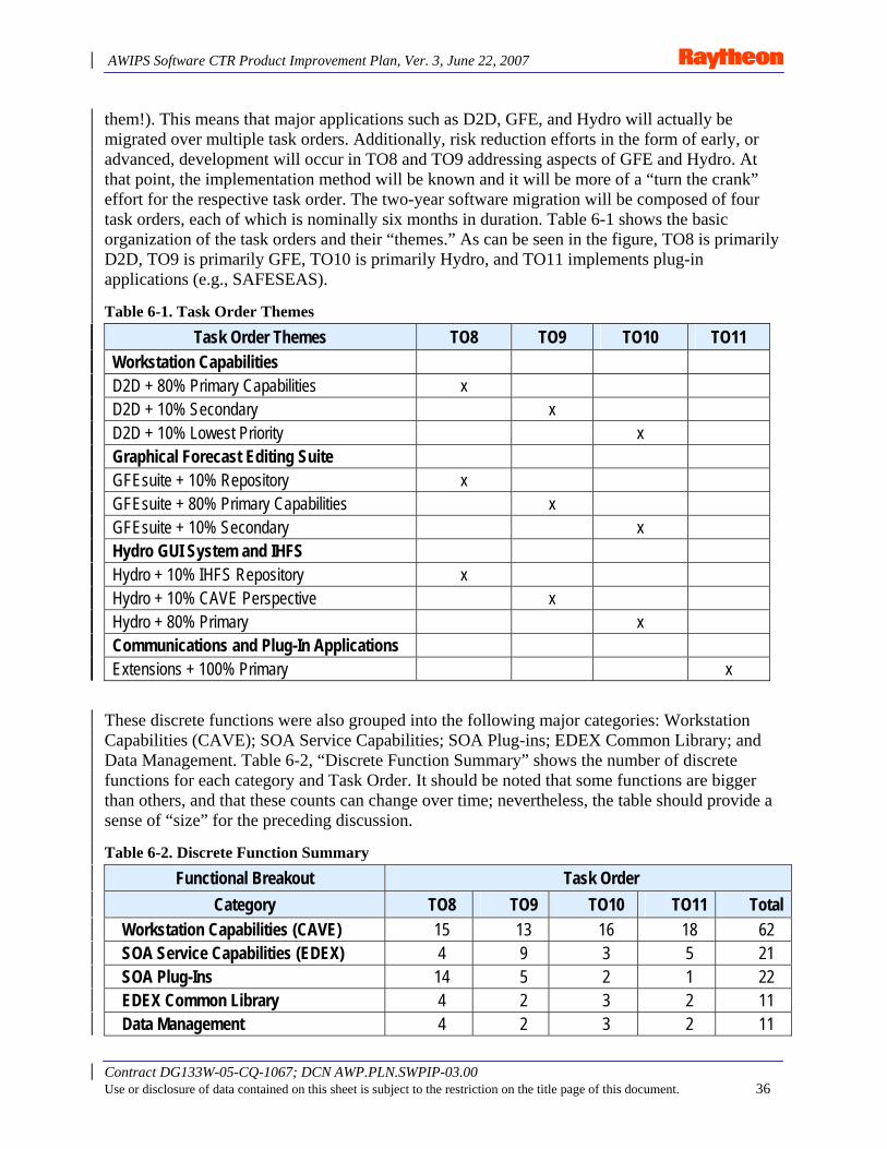
AWIPS Software CTR Product Improvement Plan, Ver. 3, June 22, 2007
Contract DG133W-05-CQ-1067; DCN AWP.PLN.SWPIP-03.00 Use or disclosure of data contained on this sheet is subject to the restriction on the title page of this document. 36
them!). This means that major applications such as D2D, GFE, and Hydro will actually be migrated over multiple task orders. Additionally, risk reduction efforts in the form of early, or advanced, development will occur in TO8 and TO9 addressing aspects of GFE and Hydro. At that point, the implementation method will be known and it will be more of a “turn the crank” effort for the respective task order. The two-year software migration will be composed of four task orders, each of which is nominally six months in duration. Table 6-1 shows the basic organization of the task orders and their “themes.” As can be seen in the figure, TO8 is primarily D2D, TO9 is primarily GFE, TO10 is primarily Hydro, and TO11 implements plug-in applications (e.g., SAFESEAS).
Table 6-1. Task Order Themes
Task Order Themes TO8 TO9 TO10 TO11 Workstation Capabilities D2D + 80% Primary Capabilities x D2D + 10% Secondary x D2D + 10% Lowest Priority x Graphical Forecast Editing Suite GFEsuite + 10% Repository x GFEsuite + 80% Primary Capabilities x GFEsuite + 10% Secondary x Hydro GUI System and IHFS Hydro + 10% IHFS Repository x Hydro + 10% CAVE Perspective x Hydro + 80% Primary x Communications and Plug-In Applications Extensions + 100% Primary x
These discrete functions were also grouped into the following major categories: Workstation Capabilities (CAVE); SOA Service Capabilities; SOA Plug-ins; EDEX Common Library; and Data Management. Table 6-2, “Discrete Function Summary” shows the number of discrete functions for each category and Task Order. It should be noted that some functions are bigger than others, and that these counts can change over time; nevertheless, the table should provide a sense of “size” for the preceding discussion.
Table 6-2. Discrete Function Summary
Functional Breakout Task Order Category TO8 TO9 TO10 TO11 Total
Workstation Capabilities (CAVE) 15 13 16 18 62 SOA Service Capabilities (EDEX) 4 9 3 5 21 SOA Plug-Ins 14 5 2 1 22 EDEX Common Library 4 2 3 2 11 Data Management 4 2 3 2 11
AWIPS Software CTR Product Improvement Plan, Ver. 3, June 22, 2007
Contract DG133W-05-CQ-1067; DCN AWP.PLN.SWPIP-03.00 Use or disclosure of data contained on this sheet is subject to the restriction on the title page of this document. 37
6.2 Migration Task Order Summary Descriptions Brief descriptions of the task orders planned during the migration phase (i.e., before deployment) are provided in this section. Additional detail will be provided in subsequent task order proposals; details may change in the future if needed.
Task Order 8, “Core Workstation Capabilities”
• Delivers the Initial Core AWIPS-II Workstation Capability. • Includes the ingest, indexing, and storage of data from the SBN for bin Lighting, GINI
Satellite, Grib1/2, RAOB, basic Text, Aircraft, Maritime, Radar, TAF, Synoptic, and METAR.
• The CAVE workstation will have core vector, raster, X-Y graphs, and text rendering. All the ingested data listed above can be rendered.
• CAVE will include the D2D-style volume browser with load modes and time correlation. • Will include D2D capabilities for displaying plot data, custom color map editing, text
display, warning generation with limited VTEC, and Skew-T views of vertical data. • The radar will have the all-tilts from ADE 0.2 with the 4-panel display linked cursor. • CAVE will have the full menus to support D2D, GFEsuite, and Hydro with actions only for
the D2D for evaluation. • Includes limited workstation modes, localization, history, and procedures. • Includes the Radar interface to the ORPG. • Includes a basic SHEF ingest capability as a risk reduction for Hydro migration planned in
T10. • Will add a framework for the GFE to CAVE as a risk reduction for TO 9. • Will implement a prototype plug-in for GFE grids and supporting services along with the
IHFS hydro database to reduce the risk of migrating GFEsuite and Hydro applications.
Task Order 9, “Graphical Forecast Editing Suite”
• Builds on T08 by migrating the major functionality in GFEsuite. • Extends CAVE with a GFE perspective that will include grid rendering with color maps and
the rendering of grid edits. • Migrates the existing Grid Manager, Spatial Editor with the editing tools. • Includes GFE watches and GFE workstation localization. • Includes workstation enhancements with a Smart Tools interface mechanism. • Continues risk reduction efforts for Hydro capabilities with a River Pro framework, time
series, and point data control. • SOA plug-ins for the GFE grids will migrate existing commands for grid management, text
management, and administration. • Extends the UtilSrv to support color maps, map projection commands, and VTEC
commands. • Includes decoders for bufr, afos, dpa, and products.
AWIPS Software CTR Product Improvement Plan, Ver. 3, June 22, 2007
Contract DG133W-05-CQ-1067; DCN AWP.PLN.SWPIP-03.00 Use or disclosure of data contained on this sheet is subject to the restriction on the title page of this document. 38
• Builds the GFE data model and tools to support the model into data management.
Task Order 10 , “Hydro GUI and IHFS”
• Extends TO9 base with Hydro capabilities. • Includes a (CAVE) hydro perspective that has hydroview, hydrogen, riverpro, report alarm,
and the MPE editor. • Includes capabilities of hydrobase, site-specific hydrologic predictor, and product tools. • Completes the GFE temporal editor to finish the GFEsuite capability. • Completes workstations enhancements for alerting. • Creates interface to the RFS to allow it to be part of the SOA. • Implements SOA plug-ins to support ingesting SHEF data from LDAD. • Implements the rate of change checker. • Implements the IHFS database with new data access objects and supporting utilities. • Encapsulates RFS.
Task Order 11, “Communications and Plug-in Applications”
• Finishes the migration by re-engineering a series of independent applications. These include the SCAN-Rapid SCAN tools, SafeSeas, Snow, Fog Monitor, FFMP, Climate Tools, Hourly Weather Roundup, Haz collect, and local storm reporting.
• Migrates hydro dam crest tool. • Completes GFE daily forecast critique and ASCII grid import/export. • Extends SOA plug-ins to support LDAR, LAPS interfaces, and LAPS tools. • Migrates the MHS to an ESB approach. • Migrates CP functionality and CP interfaces at the NCF. • Re-engineers LDAD. • Includes support for SWIT and CM Transition of AWIPS II R 1.0 code base. • Includes Sync for OB9 Corrective and Adaptive changes (Baseline Changes will be treated
separately).
Each of these Task Orders also includes:
• OB Impact analysis (changes that have been made between the end of TO7 and initiation of subsequent TOs), which may include replanning the migration tasks.
• JavaDoc for all developed code. • Copy of Raytheon Test Plan, Test Procedures, Associated Requirements Traceability Matrix
(RTM) and Test Report. • User Functional Test DR Disposition Report. • Task Order Technical Outbrief and RRD for advanced development work. • Input to training material updates as appropriate. [Note: There will be a separate Training
Task Order.]
AWIPS Software CTR Product Improvement Plan, Ver. 3, June 22, 2007
Contract DG133W-05-CQ-1067; DCN AWP.PLN.SWPIP-03.00 Use or disclosure of data contained on this sheet is subject to the restriction on the title page of this document. 39
• Redlines of AWIPS User’s Manual, System/Subsystem Design Description, and System Manager’s Manual for affected sections (delivery of updated UM, SSDD, and SMM occurs with TO 11).
• Release Notes. • Incorporating selected DRs.
6.3 Special Topics This section addresses questions that have been raised regarding other aspects of the software migration. Algorithm Selection and Verification
Question: How will algorithms be verified to produce the same results as AWIPS I, and in cases where there are multiple algorithms calculating the same thing (e.g., relative humidity), how will you select the one to use?
Response: Unless otherwise directed, only the implementation of the algorithms will change. Algorithm concerns identified by Raytheon will be raised to NWS for rapid resolution. Raytheon will construct drivers for existing and replacement implementations. Drivers will call existing or new algorithms as appropriate, with defined data sets appropriate for the algorithm. Output of existing and new algorithm implementations will be captured and compared during software unit tests. NWS is requested to participate in identification of appropriate data sets composition. Timing data will also be collected and recorded for the execution of each function. For output data set comparison, acceptable margin of differences will be coordinated. Any questionable differences will be coordinated with NWS for resolution.
Geo-registration
Question: How will you verify that satellite, radar, and other images are correctly placed on the map?
Response: Geo-registration verification is accomplished in several ways, depending on the data that is to be verified. A key feature of the AWIPS II/CAVE application is the interactive ability to display the latitude and longitude of the cursor location. This allows direct geo-registration verification of station, geo-political and topographic data. Accuracy of AWIPS II geo-registration is verified by examining the corner points of images and comparison with the source iimage data. Geo-registration of grid data will be verified using test grid sets in cylindrical equidistant projection and verifying the location of the key test features on the display. Inclusion of latitude and longitude as a parameter also will be used to verify accurate geo-registration. Differences are to be anticipated based on varying earth models. Radar geo-registration will be verified similarly. If NWS has test data sets to support this testing, Raytheon will be happy to use them.
GFESmart tools and Python
Question: Will Python be supported?
AWIPS Software CTR Product Improvement Plan, Ver. 3, June 22, 2007
Contract DG133W-05-CQ-1067; DCN AWP.PLN.SWPIP-03.00 Use or disclosure of data contained on this sheet is subject to the restriction on the title page of this document. 40
Response: While Jython was considered early in the project, it was determined that it could not adequately support numerical Python. As a result, Raytheon performed a trade study during TO7. Several approaches, including Jython, Python Bridge, and Rhino, were compared. The conclusion of the study was that the best approach will be to convert Smart Tools/Initialization to Java Script. Conversion tools will be developed to reduce Raytheon’s conversion efforts. These ttools will be provided to NWS to support local application migration. GFE Text Formatters in Python will remain in Python and be modified minimally to interface with new GFE repository. No issues are foreseen with locally developed format extensions (i.e., they should be supported iin a similar manner).
FEWS and AWIPS II
Question: We’ve heard that “FEWS” will be included in the first release of AWIPS II. Is that true?
Response: FEWS (“Flood Early Warning System”) is being pursued by the Hydro community as a “replacement” for RFS. Raytheon will execute a study task order to determine the feasibility of and approach to integrating FEWS and AWIPS II. No commitment has been made for or against FEWS inclusion in AWIPS II R1.0. However, it is unlikely that it will be included in AWIPS II R1.0 as it would require many elements to “fall into place” including additional functionality added to FEWS. It would also require agreements for re-baselining the SW CTR Project between NWS and Raytheon, and this might require a re-plan of TO sequencing (the main hydro TO is 10 but other tasks are being developed earlier). So, it is highly unlikely to occur.
Sync with OB Builds
Question: What is your approach for staying in sync with OBs?
Response: We will start with OB8.1. For DR fixes in OB8.1, 8.2, 8.3, and 9, some will be obviated with AWIPS II because AWIPS II is not likely to contain the same errors being corrected by the DR fixes. Some DRs may provide insights into problems and provide migration guidance to avoid problems in functions not yet re-implemented. DCSs in OB 8.1, 8.2, 8.3, and 9 will provide migration guidance to enhancements to functions being re-implemented. This may cause rework if the functions have already been re-implemented. New Apps in 8.2 and 8.3 will be migrated. However, because the contents of these releases were not known, or finalized at the time ROM cost estimates were made, cost and schedule impacts will be determined when sufficient information is available. This content could cause rework to migrated functions or re-planning (i.e., the Service Backup proposal for 8.3 could cause cost increase and rework). The content of OB9 is unknown as of this writing, and we will need sufficient lead time (depends on the application or change) to migrate new applications for AWIPS II R 1.0. Also, ROMs supplied to NWS may need to be revised once the content of OB 9 is known. Cost and schedule impacts will be determined when sufficient information is available.
6.3 Local Applications (LA) AWIPS II will provide a software environment that:
• Minimizes the need for “work-around” code for production operations; • Allows for “peaceful co-existence” of Baseline and LA code; and
AWIPS Software CTR Product Improvement Plan, Ver. 3, June 22, 2007
Contract DG133W-05-CQ-1067; DCN AWP.PLN.SWPIP-03.00 Use or disclosure of data contained on this sheet is subject to the restriction on the title page of this document. 41
• Allows for easier adoption into baseline where appropriate.
Field operations will be able to extend AWIPS II baseline capabilities via plugs-ins, scripts, and legacy adapters (C and Fortran). These are essentially the same capabilities to extend AWIPS II provided to the development organizations. It is anticipated that JavaScript combined with the AWIPS II micro-engine may provide for a large proportion of LA needs. Java and JavaScript will be supported; other language support (e.g., Tcl/Tk, Perl) will not be supported. The benefits of the system occur when operating within the system which generally means using the ADE capabilities to extend features for local use. Trying to support every language in use today greatly complicates the system and increases the overall cost. If a feature is not present in the ADE that is needed by any developer, it will be added to the system in a timely fashion. This is a far better approach than trying to “do it yourself” and operate outside the system.
Local Application (LA) migration is the responsibility of the NWS and field organizations. The primary project objective is to deploy AWIPS II as scheduled; therefore, LAs need to be migrated in time to avoid deployment delays, i.e., all LAs may not need to be migrated for a particular site at the time of deployment.
Types of LA include but are not limited to RFC LA, WFO LA, GFE Smart Tools, GFE Smart Initialization, production “work arounds,” data plug-ins (ingesters / decoders), and GUI-based (CAVE Plug-ins). Conversion techniques depend on the features of the particular LA. An NWS team has been formed to develop an LA migration plan framework and approach. The Regions will be involved in analyzing the LA code base and in determining the detailed migration plans. Raytheon will provide LA migration support. In addition to planning support, Raytheon will conduct Technical Interchange Meetings (TIM) with LA developers and Regions (HQ). The TIMs will include a briefing on the AWIPS II architecture and ADE capabilities as well as demos of the system and Q&A with the AWIPS II ADE developers. Raytheon will also provide software engineering consulting to illustrate and recommend how to approach migration of specific LA as well as answer questions as they arise during the LA migration effort.
AWIPS II will have configuration management locks that will prevent certain changes to system (by developers whether they are development or field operations organizations).
LAs will be configuration items in AWIPS II. Site-specific Plug-ins will be located in a separate repository/directory. These will be visible to central support to enhance support of the system and identify candidates for adding to the national baseline. The configuration item directory structure will be something like CI/. . . /base/uengine/base/site(N)/user(M) and will include u-Engine scripts, CAVE Plug-ins, SOA plug-in, localization and configuration switches, etc.
6.4 Documentation Documentation provided with ADE 1.0 will be updated as needed throughout the migration (e.g., Javadoc, Tech Brief). Current documentation that Raytheon is responsible for also includes the AWIPS User Manual (UM), Systems Manager’s Manual (SMM), System/Subsystem Design Description (SSDD), and Release Notes. This documentation will be redlined in appropriate sections with each task order, and the updated versions will be delivered with AWIPS II Release 1.0.
AWIPS Software CTR Product Improvement Plan, Ver. 3, June 22, 2007
Contract DG133W-05-CQ-1067; DCN AWP.PLN.SWPIP-03.00 Use or disclosure of data contained on this sheet is subject to the restriction on the title page of this document. 42
Updating other related documentation such as the AWIPS Integration Framework Manual (AIFM) will be the responsibility of the NWS.
6.5 DR Processing This discussion is in reference to code delivered in TO8, 9, 10, 11. The sources of the DRs are anticipated to be: NWS Developers (e.g., development organizations, local applications developers); User Functional Tests (TO8, 9, 10, 11); Independent Validation & Verification (IV&V) testing (during migration); and OTE (post AWIPS II 1.0 release). The basic process will include an NWS process and a Raytheon process. The NWS process will be to submit the DRs to the NWS focal point. The DRs will be processed to filter, disposition, and consolidate them for submittal to the Raytheon focal point. Raytheon will analyze the DRs and disposition them. Disposition may include rejection with feedback on why (e.g., enhancement - not a bug, already corrected, etc.) or disposition may include immediate or scheduled corrective action.
The DR tool Raytheon will use for this project is Trac. NWS will document DRs using e-mail in a format that facilitates entry into TRAC as has been done with IV&V efforts during ADE development.
AWIPS Software CTR Product Improvement Plan, Ver. 3, June 22, 2007
Contract DG133W-05-CQ-1067; DCN AWP.PLN.SWPIP-03.00 Use or disclosure of data contained on this sheet is subject to the restriction on the title page of this document. 43
7. Migration Risks Risk analysis has been ongoing during this project. Risks are entered into the Risk Assessment and Management Plan (RAMP) as they are identified. Migration risks are generally associated with resource management between AWIPS II and AWIPS I. These resources include Software Maintenance and Support labor and test beds. OB content is a significant driver for these resources and the appropriate balance must be set and managed to avoid schedule slips in AWIPS II. Other risks are associated with inadequate communication among the many stakeholders of AWIPS. Technical risks are not technology based as much as managing discovery and the schedule. A primary worry for many people today is whether the performance of AWIPS II will be adequate at operational loadings. Because the whole system needs to be in place to completely determine system performance, reliable performance predictors need to be developed to test elements of the system. These tests need to occur early enough to apply correction if needed. The overall assessment is that there are no high risks for this project; nevertheless, the project must be carefully managed and the collective eye needs to be on the ball.
All risks are logged in the RAMP Risk Register. Reports are available on the Raytheon AWIPS O&M Program Management Portal,
AWIPS Software CTR Product Improvement Plan, Ver. 3, June 22, 2007
Contract DG133W-05-CQ-1067; DCN AWP.PLN.SWPIP-03.00 Use or disclosure of data contained on this sheet is subject to the restriction on the title page of this document. 44
8. Training Several groups will need “training”4 on the ADE/SDK and/or System Administration. Application usage training will not be required for AWIPS II Release 1.0 because the “black box” approach will replicate the current system functionality and behavior. Groups requiring training include:
• ADE/SDK: Dev Orgs, Local apps developers, SST/HST, NCF, SMS. • System Administration: ITO/ESA, App POC, SST/HST, NCF, Dev Org Sys Admin.
[Note: Individuals within these groups may not need all of the training in the type shown. Note also that some group(s) may not be listed. For example, application points of contact (POC) may only need the localization portion of the Sys Admin training.]
Training activity is composed of two major categories – course content development and training delivery. NWS is responsible for training delivery to NWS/NOAA personnel, and Raytheon is responsible for training Raytheon Team personnel.
Raytheon will support NWS training efforts by providing technical content for the training material, and technical consulting during courseware development. Raytheon may also support the NWS delivery of classes by “sitting-in” during initial classes to provide technical support to instructors (i.e., answer questions from the class.)
Raytheon has delivered the initial developer training with TO3, 4, 5, and 6. Developer training course content was developed for these classes and updated for consistency with TO6. As developer resources are added to the ADE/SDK, training material updates will be made and technical briefings delivered with the respective task orders. Additional Raytheon training support will be delivered via a specific task order that is described later in this section.
In general, there are a large number LA developers who need ADE/SDK training (estimated at ~170). This could be an issue given that we would like to give the Field one year to convert their local apps (note that this duration is a guess and that it may not take that long; one region estimated that it would need a year, inclusive of training). That said, the precise technique for migrating a specific LA will be determined on a case-by-case basis, and not every migration requires the more advanced capabilities of the ADE. Therefore, if initial LA developer training is targeted to support LA migration, the requirements may be significantly simplified.
It should be remembered that classroom training (of a few days) is merely an introduction. The ability and skill to use the ADE/SDK effectively occurs through hands-on experience over time.
8.1 Developer Training – Suggested Approach Given the previous discussion and other realities, we have a recommended approach for training delivery. The major critiques from the prototype training were that people cannot effectively absorb the material if the classes are too long (a full day was considered too long) and that more ”how to” examples were needed. WebEx seemed to be acceptable for ADE training delivery
4 Training can take many forms and formal classroom training is just one.
AWIPS Software CTR Product Improvement Plan, Ver. 3, June 22, 2007
Contract DG133W-05-CQ-1067; DCN AWP.PLN.SWPIP-03.00 Use or disclosure of data contained on this sheet is subject to the restriction on the title page of this document. 45
given travel and scheduling constraints. Also, WebEx class size is not constrained by classroom equipment. Therefore, the recommended approach is to deliver training in 1- to 3-hour (remote) sessions (3 hours max) on a weekly or biweekly basis. The training material modules support this type of approach, and this allows individual trainees to attend only the sessions they need. Although the classes would be delivered by non-Raytheon team personnel, the Raytheon team ADE/SDK experts would sit in on the sessions to support the instructors by responding to technical questions that the instructor cannot answer. The Q/A could be used to refine the course content and/or develop an FAQs addition.
“How to” examples will be developed naturally with the execution of TO8. Therefore, we are planning to update the training material following TO8 completion. This training material supports all developer training regardless of the group (e.g., dev org, field).
This approach should provide rapid introduction to the ADE while providing the developer with resources to use in developing their skill.
8.2 Developer Training Syllabus The developer training syllabus is modular and supports the approach discussed in the previous section. It includes a “Foundation” course on Service Oriented Architectures; the NWS is contracting a third party to deliver this “Foundation” course.
The training syllabus is as follows:
• Foundation Course5 • Script Development
– Using script language – Extending script language
• Cave Plug-ins – Creating menus in CAVE – Using the localization pattern within CAVE
• SOA Plug-ins – Data ingest – Using Data access – Micro Engine extensions – Configuring Mule end points
• Using the Localization Pattern – Extending the meteo library
5 Available from Learning Tree International. Suggested additional courses which are also available from Learning Tree include Spring/hibernate, Best Practices in Java, and Eclipse IDE.
AWIPS Software CTR Product Improvement Plan, Ver. 3, June 22, 2007
Contract DG133W-05-CQ-1067; DCN AWP.PLN.SWPIP-03.00 Use or disclosure of data contained on this sheet is subject to the restriction on the title page of this document. 46
8.3 System Administration Syllabus As of this writing, the System Administration (SA) course delivery method is still to be determined. However, this course is not expected to begin until March 2009, so there is time to work out these details. The NWS SOA Foundation course would be useful to anyone; however, if it is not available, the AWIPS II architecture should be presented. The following lists the topics to be covered in the SA Course.
• Foundation Course – NWS SOA and/or AWIPS II architecture overview.
• Installation (w/ rollback) • Clustering and other hardware considerations • Localization configuration and data needs • Monitoring with JMX and other tools • Local application configuration management • Security
8.4 Training Support Task Order Description The training support Task Order includes upgrading the training material delivered with Task Order 6. It will add material for new ADE features as well as “how to” examples for JavaScript and micro-engine usage, creating CAVE plug-ins, and data plug-ins.
Technical documentation to support System Administration training course development will be delivered with Task Orders 8, 9, 10, and 11 as the capabilities are developed. Note that this is not special content packaging. Technical support will be provided to the National Weather Service Training Division (NWSTD) for courseware development. This support will take the form of a briefing of the material, reviewing courseware for technical accuracy, and answering questions.
Training delivery support will be provided by sitting in initial (WebEx) sessions to answer technical questions as needed. Face-to-face training delivery support will be by telephone. This will be provided for both Developer and Sys Admin training.
AWIPS Software CTR Product Improvement Plan, Ver. 3, June 22, 2007
Contract DG133W-05-CQ-1067; DCN AWP.PLN.SWPIP-03.00 Use or disclosure of data contained on this sheet is subject to the restriction on the title page of this document. 47
9. Deployment “Deployment” begins when OTE is complete, and is planned to take six months. OTE will occur for selected sites, and once it is complete for a site, that site is considered to be “deployed”. Therefore, deployment here refers to the remaining sites. Raytheon support during deployment will follow normal practices and service levels.
OTE, deployment, and O&M transition details will be determined with a Deployment Planning Task Order. This task order is currently planned to be four months long, and will start July 1, 2008. The planning efforts will require Raytheon and NWS participation. NWS participation will include Regional and Site representatives. The types of details to be determined include:
• OTE procedure and support details, including support details for the NCF, helpdesk, application support, etc.
• Field Site readiness details such as: – Site sequencing with service backup capability – Technical details of messaging cross-over (e.g., MHS / ESB) – Data cross-over details and initialization (e.g., VTEC, GFE) – Installing and testing AWIPS II without removing AWIPS I – Rollback procedures
• O & M Transition details of transitioning for: – Release Management – SW Integration and Test – Configuration Management – Applications Software Maintenance
O&M Transition is discussed in more detail in the following section.
AWIPS Software CTR Product Improvement Plan, Ver. 3, June 22, 2007
Contract DG133W-05-CQ-1067; DCN AWP.PLN.SWPIP-03.00 Use or disclosure of data contained on this sheet is subject to the restriction on the title page of this document. 48
10. Transition to O&M Transition to Operation and Maintenance is planned to occur with the first deployed version of AWIPS II. Detailed planning for this transition will begin one year prior to deployment in the “Deployment Planning” task order discussed in the Section 9.
The transition to O&M includes transitioning Software Integration and Test Environment (including configuration management), Applications Support & Maintenance, and the NCF/helpdesk. While transition details and timing will vary with each area, all groups will need to understand the AWIPS II software/system environment before determining the details of transitioning support systems (i.e., people, procedures, equipment). Additionally, although we are introducing a new system, the fundamentals of the overall support systems will not change. Because the basic requirements for SWIT and CM do not change, the general processes and framework will remain largely the same as they are today. Changes will occur mainly in procedure details. For example, some software infrastructure test procedures will change, and other test procedures may not change. We will only change what needs to change because of AWIPS II; we will not perform a wholesale revamp of the O&M systems. Our general principle is to Minimize disruption to the current System while meeting the need. As noted in section 2.4, preliminary deployment and transition plan described in this document assumes that OB9 deployment will be complete by the end of April 2009, and that OB9 maintenance releases will be limited to critical DRs and RHEL upgrade in order to ensure that appropriate resources are available to support the transition to and preparation for O&M of the new AWIPS II software.
10.1 Release Management “Release Management” as used here refers to the overall framework of processes beginning with the SREC and ending with delivery. Fundamental release products will not change (for example, release notes, documentation updates). The current release process is shown in Figure 10-1. In examining this figure, it is easy to see why things will not change much at this level of detail.

AWIPS Software CTR Product Improvement Plan, Ver. 3, June 22, 2007
Contract DG133W-05-CQ-1067; DCN AWP.PLN.SWPIP-03.00 Use or disclosure of data contained on this sheet is subject to the restriction on the title page of this document. 49
Figure 10-1. AWIPS I Release Management Process
10.2 SWIT, CM, and Test Environment Transition We will transition AWIPS II Release 1.0 (see Figure 2-3) from the Raytheon team in Omaha to the Silver Spring SWIT organization first. This will occur during TO 11. This will not require the multi-development organization approach applied to today’s OB process and will provide a simpler initial step. We will reuse AWIPS I Test procedures to the extent possible, starting with TO8. We will start the Knowledge Acquisition Process (KAP) to transition the SWIT and CM Organization during TO11 (assuming people availability). The SWIT Team can also observe and/or participate in TO8 – 11 testing if they are available.
Following the AWIPS II Release 1.0 handoff, the multi-organization integration process will be implemented. This will be done in time for new AWIPS II applications releases starting around June 2010 (Figure 2-3).
The Test Environments (Test Beds) will need to be coordinated between AWIPS II and AWIPS I during code migration and O&M transition. Although this will require careful coordination, AWIPS II can be installed and tested on a test bed without removing AWIPS I. This should improve scheduling flexibility during transition. After transition, multiple AWIPS II releases could co-exist on a single test bed with one at a time being active for testing. Details of the Test transition will be planned in Deployment Planning TO.
CM for AWIPS II will remain in Omaha until Release 1.0, and transition to SMS during TO 11. This will include DR processing/tracking and incorporation during OTE as needed. AWIPS II
CM Process
SREC / DR Team
- Release Content
- Requirements- Funding
α /β SyATSwIT
Support:Software Problem Resolution/User
Support
Emergency
Major
DR Life Cycle
- Release Types
Release Flow
- Burn DVD- Support National Install
Install
Verification- System Verification Review
MDL GSDOHD ASMCDSSECNMAP
SWIT
- DVD
- Selected Field Sites Test- Install Procedures and Functionality Changes
- Push Deployment
α /β SyAT
- Dry-run SyAT- Government Witness- Test Readiness Review
SIT
- Full Integration- Performance Monitoring
SwIT
- Stress Test
- New Functionality
- Interfaces
- Performance Test
Pre-SwIT
- Verifies Install- Launches New Functionality
IntegrationBuild
Development Labs
Configuration Management Processes
DEVELOPMENT
IntegrationBuild
IntegrationBuild
IntegrationBuild
IntegrationBuild
Work Products- Test Plan- Test Cases- Test Results- Test Summary Rpt
Work Products
Work Products- Requirements- Design- Test Plan/Results- Code- Reviews
NCF
NCF
Business Functional Requirements
Technical ReqmntsPlanning Design Construction
Functional Test Closure
Integration Handoff
Business Functional Requirements
ReviewMaintenance
- Release Plan- Project Schedule- Productivity Insight
AWIPS SMS Release & Support Flow – v02 061110
PIT
AWIPS Software CTR Product Improvement Plan, Ver. 3, June 22, 2007
Contract DG133W-05-CQ-1067; DCN AWP.PLN.SWPIP-03.00 Use or disclosure of data contained on this sheet is subject to the restriction on the title page of this document. 50
will be in a complete CM environment using the open source tools “Subversion” and “TRAC.” We will evaluate Subversion versus PVCS for going forward during detailed deployment planning.
10.4 Application Maintenance We will begin transition with the KAP for applications and infrastructure starting at AWIPS II Release 1.0 as shown on Figure 2-3. The Raytheon Omaha team will support OTE & deployment, with Application Support & Maintenance (ASM) taking “primary” role approximately six months after release (Jan 2010). This means the ASM group will perform DR Processing and incorporation; the Raytheon Omaha will be available to help if needed. ASM will be provided AWIPS II Task Order deliverables for examination / study for TO8, 9, 10, and 11. These are shown on Figure 2-2 as “O&M Transition Prep and Coordination” tasks.
10.5 NCF and User Support NCF support will be in place at the start of OTE. This will include network operations support, site monitoring, and JMX monitoring (new with AWIPS II). Helpdesk and Remedy usage procedures will be updated and new draft SOPs will be in place. These will be tested and rehearsed prior to OTE. NCF staff will receive AWIPS II System Administration training, and some staff will receive Developer training as required. Raytheon is responsible for NCF staff and Raytheon team training. The SST and HST will receive similar training through NWS classes. Details of NCF and support readiness requirements will be determined during the Deployment Planning Task Order.
10.6 Governance AWIPS II delivery brings the opportunity to change the release paradigm while enabling easier extension by the Field Operations. This also provides opportunity for problems resulting from uncontrolled change. “Governance” is the term generally used to refer to the rules and processes for managing change to the AWIPS II software environment. As with the rest of O&M transition the fundamentals shouldn’t change that much except for possibly scope and organization participation.
In the big picture, governance is fundamentally concerned with decision making, and for IT systems like AWIPS it generally starts with funding/resource decisions. How much will be spent on “IT”? How will it be spent? Next, governance is concerned with change decisions and related processes such as managing change authorizations to AWIPS II; adding new capability; applying corrective actions; and setting priorities (which is a form of “how to expend resources”).
Big-picture issues need to be addressed at some point, but governance for DR incorporation from TO testing needs attention first, and it needs to be in place by year end 2007, i.e., how are DRs dispositioned, who decides, etc. These are not necessarily difficult things to define; they just need to be done. Reaching agreement among the stakeholders will take time.
Raytheon will deliver an initial framework in October 2007. NWS and Raytheon will start with this framework and jointly develop further refinement of the scope, structure, and process for the governance model. Some portions of the model need to be drafted and agreed to well before AWIPS II deployment.
AWIPS Software CTR Product Improvement Plan, Ver. 3, June 22, 2007
Contract DG133W-05-CQ-1067; DCN AWP.PLN.SWPIP-03.00 Use or disclosure of data contained on this sheet is subject to the restriction on the title page of this document. 51
11. Government Testing Over the next two and one-half years the NWS will conduct several types of tests on AWIPS II. These types of testing will include: independent validation and verification (IV&V), User Functional Tests (UFT), Operational Test and Evaluation (OTE), and (security) certification and accreditation (C&A). The NWS is responsible for the planning and execution of these tests. However, Raytheon will provide technical support depending on the specific testing. Support may take the form of fixing “work stops,” processing trouble tickets, providing DR disposition reports, and assisting in defining performance test procedures. Details of this testing are beyond the scope of this document; however, a few points on each are provided in this section.
Independent Validation and Verification (IV&V)
IV&V started with ADE 0.1 release and will occur throughout the migration period. Raytheon technical support will consist of assisting in defining performance tests, and providing DR disposition reports.
User Functional Test (UFT)
The UFT will occur at the end of TO8, 9, 10, and 11. It is similar to the Pre-Integration Test (PIT) done today for new functionality. It is planned for a nominal three weeks (longer than today’s PIT). It will provide for tests of “forecaster functionality” and will be performed by field personnel (e.g., forecasters). The primary purpose of the UFT is to verify that the functionality adequately mimics AWIPS I for end-user functions delivered with a specific TO. Raytheon’s technical support will consist of fixing work stops, and providing a DR disposition report for DRs submitted to Raytheon for the UFT.
Operational Test & Evaluation (OTE)
OTE will occur as soon after AWIPS II 1.0 Release as possible. The precise timing will be determined during the deployment planning task. OTE is currently planned for six months, although there are NWS discussions on this point are ongoing. The scope and plan are currently under development by an NWS Integrated Working Team (IWT). Raytheon technical support will consist of normal Trouble Ticket processing, which includes priority resolution of work stops. Note that the AWIPS support organizations will be ready to provide this support when OTE begins. Raytheon also expects to participate in OTE performance testing definition.
Certification & Accreditation (C&A)
AWIPS (the total system) will go through a C&A update in mid-2008. AWIPS II will be a revision to that C&A plan addressing the AWIPS II software changes. This is expected to be primarily testing of technical controls (e.g., authentication, authorization) of AWIPS II within the security architecture of the AWIPS system (e.g., hardened perimeter). As such it is not expected to be a major departure from the approaches today. C&A can start and occur concurrently with OTE. If the technical controls test is successful, the overall process is expected to take eight weeks.