software defined radio for processing gnss signals - …jmfriedt.free.fr/efts_gps.pdf · software...
TRANSCRIPT

Software definedGPS receiver
Friedt & al.
Intro & basics
User perspective
Dev perspective
Got it !
What next ...
Software Defined Radio for processing GNSSsignals
S. Martinez Gutierrez, J.-M Friedt, G. Cabodevila, P.Y Bourgeois,E. Rubiola
FEMTO-ST Time & Frequency, Besancon, France
www.femto-st.fr first-tf.com
Slides available at http://jmfriedt.free.fr/efts_gps.pdf
January 31, 20151 / 36

Software definedGPS receiver
Friedt & al.
Intro & basics
User perspective
Dev perspective
Got it !
What next ...
Introduction: GNSSGNSS:
• Spaceborne atomic clocks 1
• Aim: use of ultrastable time references beyond positioning ...• ... eg. tide gauge 2, moisture detection 3 ,
phase monitoring (TEC)• Requires at least phase recovery.• Educational purpose: detailed understanding
of the steps needed to complete a GPSreceiver low phase noise LO !
Use a low cost DVB-T receiver for acquisition:• 8 bit-resolution
• poor sensitivity ⇒ pre-amplified antenna
• 2.4 MHz measurement bandwidth limited byUSB bandwidth (I, Q components)
• gnss-sdr /w GNURadio processing blocks
1http://geodesie.ign.fr/journee-gnss-science/2
K.M. Larson: http://spot.colorado.edu/~kristine/Kristine_Larson/Home.html3
Bock et. al., West African Monsoon observed with ground-based GPS receivers ..., J. Geophysical Research 113, D21105 (2008),at http://onlinelibrary.wiley.com/doi/10.1029/2008JD010327/pdf 2 / 36
Software definedGPS receiver
Friedt & al.
Intro & basics
User perspective
Dev perspective
Got it !
What next ...
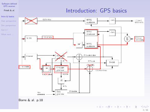
Introduction: GPS basics
Borre & al. p.18
3 / 36

Software definedGPS receiver
Friedt & al.
Intro & basics
User perspective
Dev perspective
Got it !
What next ...
Objectives• a modulator generates the information, here encoded in the phase
of the carrier
• the information is carried on a signal whose frequency varies(Doppler, thermal drift of LO)
• recovering the transmitted information is a matter of eliminatingcarrier information
• two degrees of freedom (carrier frequency and CDMA for satelliteidentification) will require two feedback loops to recover theinformation
⇒ carrier recovery and code position (delay) recovery
PRN (1.023 Mbps)
NAV (50 bps)
PRN
NAV
feedback loop
feedback loop
1575.42 MHz+/−df
4 / 36

Software definedGPS receiver
Friedt & al.
Intro & basics
User perspective
Dev perspective
Got it !
What next ...
SDR: user perspective
• DVB-T dongle application : L1 C/A at 1.023 MHz barely meets theNyquist criteria when sampling at 2 MHz (no need to: strongassumption on modulation, i.e. 2/1.023=1.95 symbol/period)
• Receiver sensitivity ?
Receiver 137 MHz 434 MHz 1090 MHz 1500 MHz
E4000 -105 -105 -96 -95R820T -112 -112 -109 -102FC0013 -112 -111 -76 -58
Receiver 137 MHz 434 MHz 1090 MHz 1500 MHz
E4000 -109 -110 -101 -101R820T -117 -119 -113 -110FC0013 -116 -115 -80 -62
Carrier power (dBm) needed for a demodulated signal SNR of 10 dB. All dongles set
to their max gain (RF=39 dB and IF=45 dB for E4000, RF=50 dB for R820T,
RF=20 dB for FC0013). Top: FM, bottom: AM.
5 / 36

Software definedGPS receiver
Friedt & al.
Intro & basics
User perspective
Dev perspective
Got it !
What next ...
Link budget: is it possible ?• Emitted power: 25.6 W=14 dBW
• 13 dBi antenna gain
• FSPL (21000 km)=182 dB
• Received power=-155 dBW=-125dBm
• Themal noise in a 2 MHz BW:-174 dBm/Hz+10·log10(2 MHz)=-111 dBm
• Compression (coding) gain:BW×τ=2 MHz×1 ms=33 dB
• SNR=(−125 + 33)− (−111)=19 dB• Receiver antenna amplification: +27 dB
⇒ (-125+27)-(-102DVB−T ) '4 dB SNR
R820T+RTL2832U based DVB-T receiver, bias T, antenna (30$) 4
4http://www.adafruit.com/product/960: 13$ antenna andhttp://www.dx.com/p/
rtl2832u-r820t-mini-dvb-t-dab-fm-usb-digital-tv-dongle-black-170541:12$ dongle
6 / 36

Software definedGPS receiver
Friedt & al.
Intro & basics
User perspective
Dev perspective
Got it !
What next ...
SDR: user perspective• Frequency offset budget: LO offset (±50 ppm) & drift
(temperature) + remote carrier dependence with position in space• Identify carrier frequency mismatch: carrier recovery (phase) issue• Temperature dependence : front-end-cal 5 over > a week
-62
-61
-60
-59
-58
-57
-56
-55
0 50 100 150 200 250 300 350
off
set
freq
uen
ce (
ppm
)
temps (h)
5
10
15
20
25
30
0 50 100 150 200 250 300 350
tem
per
ature
(deg
C)
temps (h)
PSK signal is hidden by phase rotation ifincoming carrier and LO mismatch
[......7...........19.......27.....]
Total signal acquisition run time 11.703 [seconds]
Reference Time:
GPS Week: 790
GPS TOW: 209107 16728.560000
~ UTC: Tue Oct 14 12:05:08 2014
Current TOW obtained from SUPL assistance = 209107
Reference location (defined in config file):
Latitude=47.3 []
Longitude=6 []
Altitude=10 [m]
Doppler analysis results:
SV ID Measured [Hz] Predicted [Hz]
7 92437.50 1848.25
19 94125.00 3080.82
27 93000.00 2116.75
Parameters estimation for Elonics E4000 Front-End:
Sampling frequency =1999884.81 [Hz]
IF bias present in baseband=90736.35 [Hz]
Reference oscillator error =-57.60 [ppm]
Corrected Doppler vs. Predicted
SV ID Corrected [Hz] Predicted [Hz]
7 1701.15 1848.25
19 3388.65 3080.82
27 2263.65 2116.75
GNSS-SDR Front-end calibration program ended.
5gnss-sdr.org 7 / 36

Software definedGPS receiver
Friedt & al.
Intro & basics
User perspective
Dev perspective
Got it !
What next ...
SDR: user perspectiveCalculation of Doppler shift as a function of orbital parameters
θ
90−θ
Earth
orbit
HH’
P
R
R+r
r
v
v
• Orbiting at 20000 km in 12 hours⇒ 2π(6400 + 20000)/12 =13800 km/h=3840 m/s
• Receiver at position P observes thesatellite from horizon to horizon HH′.
• At H, velocity vector ~v along thesatellite trajectory is projectedtowards P along ~v‖ with ϑ meeting
the condition sin(ϑ) = RR+r
and
hence |~v‖| = |~v | · cos(90− ϑ) =|~v | · sin(ϑ) = |~v | · R/(R + r).
• Here|~v‖| = 13800 ·6400/(6400+20000) =3345 km/h and the Doppler shift is∆f = f0 · |~v‖|/c = ±4800 Hz'3.1 ppm
8 / 36

Software definedGPS receiver
Friedt & al.
Intro & basics
User perspective
Dev perspective
Got it !
What next ...
SDR: user perspectiveCalculation of Doppler shift as a function of orbital parameters
-40
00
-20
00 0
20
00
40
00
0 5
10
15
20
25
Doppler shift (Hz)
tim
e (h
)
• Orbiting at 20000 km in 12 hours⇒ 2π(6400 + 20000)/12 =13800 km/h=3840 m/s
• Receiver at position P observes thesatellite from horizon to horizon HH′.
• At H, velocity vector ~v along thesatellite trajectory is projectedtowards P along ~v‖ with ϑ meeting
the condition sin(ϑ) = RR+r
and
hence |~v‖| = |~v | · cos(90− ϑ) =|~v | · sin(ϑ) = |~v | · R/(R + r).
• Here|~v‖| = 13800 ·6400/(6400+20000) =3345 km/h and the Doppler shift is∆f = f0 · |~v‖|/c = ±4800 Hz'3.1 ppm
9 / 36

Software definedGPS receiver
Friedt & al.
Intro & basics
User perspective
Dev perspective
Got it !
What next ...
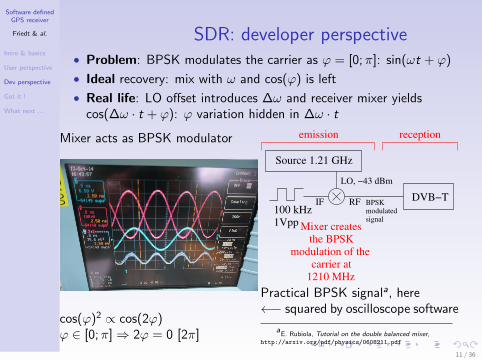
SDR: developer perspective
• Problem: BPSK modulates the carrier as ϕ = [0;π]: sin(ωt + ϕ)
• Ideal recovery: mix with ω and cos(ϕ) is left
• Real life: LO offset introduces ∆ω and receiver mixer yieldscos(∆ω · t + ϕ): ϕ variation hidden in ∆ω · t
Mixer acts as BPSK modulator
cos(ϕ)2 ∝ cos(2ϕ)ϕ ∈ [0;π]⇒ 2ϕ = 0 [2π]
−1
−0.5
0
0.5
1
0 500 1000 1500 2000
signal
(u.a
.)
temps (u.a.)
0
0.2
0.4
0.6
0.8
1
0 500 1000 1500 2000
signal
2 (u.a
.)
temps (u.a.)
0
100
200
300
400
500
800 850 900 950 1000 1050 1100 1150 1200
FF
T(s
ignal
) (u
.a.)
frequence(u.a.)
0
200
400
600
800
1000
800 850 900 950 1000 1050 1100 1150 1200
FF
T(s
ignal2 )
(u.a
.)
frequence(u.a.)
FFT
X2
FFT
modulation
po
rteu
se
po
rteu
se (
ab
sen
te)
Carrier recovery by squaring BPSK
10 / 36
Software definedGPS receiver
Friedt & al.
Intro & basics
User perspective
Dev perspective
Got it !
What next ...
SDR: developer perspective• Problem: BPSK modulates the carrier as ϕ = [0;π]: sin(ωt + ϕ)
• Ideal recovery: mix with ω and cos(ϕ) is left
• Real life: LO offset introduces ∆ω and receiver mixer yieldscos(∆ω · t + ϕ): ϕ variation hidden in ∆ω · t
Mixer acts as BPSK modulator
cos(ϕ)2 ∝ cos(2ϕ)ϕ ∈ [0;π]⇒ 2ϕ = 0 [2π]
DVB−TBPSKmodulatedsignal
Source 1.21 GHz
Mixer createsthe BPSK
modulation of thecarrier at
1210 MHz
LO, −43 dBm
100 kHz1Vpp
RFIF
receptionemission
Practical BPSK signala, here←− squared by oscilloscope software
aE. Rubiola, Tutorial on the double balanced mixer,
http://arxiv.org/pdf/physics/0608211.pdf
11 / 36

Software definedGPS receiver
Friedt & al.
Intro & basics
User perspective
Dev perspective
Got it !
What next ...
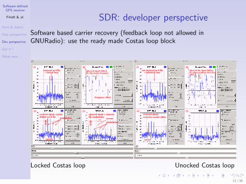
SDR: developer perspective
Software based carrier recovery (feedback loop not allowed inGNURadio): use the ready made Costas loop block
12 / 36
Software definedGPS receiver
Friedt & al.
Intro & basics
User perspective
Dev perspective
Got it !
What next ...
SDR: developer perspective
Software based carrier recovery (feedback loop not allowed inGNURadio): use the ready made Costas loop block
modulation
30
dB
(1)
(3)
modulation
carrier
squared signal = removes
the modulation
20
dB
phase of signal shiftedby the carrier frequency
(2)
(4)
f∆
frequency offset
= locked loopcentered on 0 Hz
received signal: carrier
shifted wrt 0 Hz
carrier
(1)
(3)
(2)
(4)
phase of the signal hiddennot centered on 0 Hz= unlocked loop by phase rotations du to freq.
offset
excessive carrier offset
received signal:
carrier
Locked Costas loop Unocked Costas loop
13 / 36
Software definedGPS receiver
Friedt & al.
Intro & basics
User perspective
Dev perspective
Got it !
What next ...
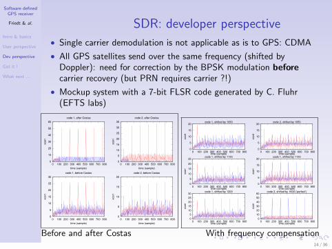
SDR: developer perspective
• Single carrier demodulation is not applicable as is to GPS: CDMA
• All GPS satellites send over the same frequency (shifted byDoppler): need for correction by the BPSK modulation beforecarrier recovery (but PRN requires carrier ?!)
• Mockup system with a 7-bit FLSR code generated by C. Fluhr(EFTS labs)
0
10
20
30
40
50
60
0 100 200 300 400 500 600 700 800
xco
rr
time (sample)
code 1, after Costas
0
5
10
15
20
25
30
35
0 100 200 300 400 500 600 700 800
xco
rr
time (sample)
code 2, after Costas
0
5
10
15
20
25
30
0 100 200 300 400 500 600 700 800
xco
rr
time (sample)
code 1, before Costas
0
5
10
15
20
0 100 200 300 400 500 600 700 800
xco
rr
time (sample)
code 2, before Costas
0
5
10
15
20
0 100 200 300 400 500 600 700 800
xco
rr
time (sample)
code 1, shifted by 1050
0
5
10
15
20
25
0 100 200 300 400 500 600 700 800xco
rr
time (sample)
code 1, shifted by 1120
0
5
10
15
20
25
30
0 100 200 300 400 500 600 700 800
xco
rr
time (sample)
code 1, shifted by 1200
0
5
10
15
20
0 100 200 300 400 500 600 700 800
xco
rr
time (sample)
code 2, shifted by 1050
0
5
10
15
20
0 100 200 300 400 500 600 700 800
xco
rr
time (sample)
code 1, shifted by 1120
0
10
20
30
40
50
60
0 100 200 300 400 500 600 700 800
xco
rr
time (sample)
code 2, shifted by 1600 (’perfect’)
Before and after Costas With frequency compensation14 / 36
Software definedGPS receiver
Friedt & al.
Intro & basics
User perspective
Dev perspective
Got it !
What next ...
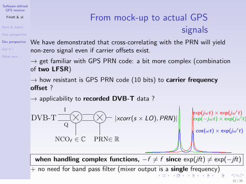
From mock-up to actual GPSsignals
We have demonstrated that cross-correlating with the PRN will yieldnon-zero signal even if carrier offsets exist.
→ get familiar with GPS PRN code: a bit more complex (combinationof two LFSR)
→ how resistant is GPS PRN code (10 bits) to carrier frequencyoffset ?
→ applicability to recorded DVB-T data ?
DVB-T |xcorr(s × LO),PRN)|Q
I
NCOf ∈ C PRN∈ R
exp(jωt)× exp(jω′t)
cos(ωt)× exp(jω′t)
exp(−jωt)× exp(jω′t)
when handling complex functions, −f 6= f since exp(jft) 6= exp(−jft)
+ no need for band pass filter (mixer output is a single frequency)
15 / 36

Software definedGPS receiver
Friedt & al.
Intro & basics
User perspective
Dev perspective
Got it !
What next ...
10-bit PRN code resistance tocarrier offet
0
50
100
150
200
250
0 500 1000 1500 2000
xcorr
(a.u
.)
sample offset (no unit)
PRN1,PRN1PRN2,PRN1
PRN1,1.003*PRN1PRN1,1.01*PRN1
0
50
100
150
200
250
1000 1020 1040 1060 1080 1100
xcorr
(a.u
.)
sample offset (no unit)
PRN1,PRN1PRN2,PRN1
PRN1,1.003*PRN1PRN1,1.01*PRN1
1 more o f f ; c l o s e a l l ; c l e a r a l ls e t ( 0 , ” d e f a u l t a x e s f o n t n a m e ” , ” H e l v e t i c a ” )
3a=cacode ( [ 1 : 3 1 ] , 1 ) ;
5 a=a ’ ;a=a−mean ( a ) ;
7 p l o t ( x c o r r ( a ( : , 1 ) , a ( : , 1 ) ) , ’ r ’ )h o l d on
9 p l o t ( x c o r r ( a ( : , 1 ) , a ( : , 2 ) ) )x l a b e l ( ’ sample o f f s e t ( no u n i t ) ’ )
11 y l a b e l ( ’ x c o r r ( a . u . ) ’ )
13 h o l d ona2=cacode ( 1 , 1 . 0 0 3 ) ; a1=cacode ( 1 , 1 ) ; p l o t ( x c o r r
( a1−mean ( a1 ) , a2−mean ( a2 ) ) , ’ c ’ )
15 a2=cacode ( 1 , 1 . 0 1 ) ; a1=cacode ( 1 , 1 ) ; p l o t ( x c o r r (a1−mean ( a1 ) , a2−mean ( a2 ) ) , ’ g ’ )
% 10 kHz /1023 kHz=0.01
cacode.m available at MatlabCentrala
aK.S. Raju & al., Digital GPS Signal Generator for L1
Band, Signal & Image Processing: An International Journal(SIPIJ) 3 (6), Dec. 2012, available athttp://airccse.org/journal/sipij/papers/3612sipij07.pdf
16 / 36

Software definedGPS receiver
Friedt & al.
Intro & basics
User perspective
Dev perspective
Got it !
What next ...
Application to real GPS signals
• gnss-sdr provides a calibration software that stores the recordedsamples (2 MS/s) in a temporary file
• when calibrating the dongle, we have saved the result of thegnss-sdr calibration process and the raw sample
• we now process these datasets and compare our analysis with thoseof gnss-sdr
x=r e a d c o m p l e x b i n a r y ( ’ 1413968929 c a p t u r e . dat ’ ) ;
2 t ime =[0:1/2 e6 : l e n g t h ( x ) /2 e6 ] ’ ; t ime=t ime ( 1 : end−1) ;
4 f o r m=1:37a=cacode (m, 2 / 1 . 0 2 3 ) ; a=a−mean ( a ) ;
6 l =1; m % d i s p l a y s a t PRNf o r f r e q =8e4 : 2 0 0 : 1 e5 % run through p o s s i b l e f r e q u e n c y o f f s e t s : c f f r o n t−end−c a l
8 mysine=exp ( j∗2∗p i∗(− f r e q )∗t ime ) ; % LOxx=x .∗ mysine ; % f r e q u e n c y s h i f t t h e s i g n a l
10 [ u ( l ,m) , v ( l ,m) ]=max ( abs ( x c o r r ( a , xx ) ) ) ; % check f o r c r o s s c o r r e l a t i o n max .l=l +1;
12 endend
14 f i g u r eimagesc ( abs ( u ) )
Notice the extended frequency offset range: hi accuracy LO will speedup acquisition time
17 / 36

Software definedGPS receiver
Friedt & al.
Intro & basics
User perspective
Dev perspective
Got it !
What next ...
Application to real GPS signals
2D plot with PRN number as X-axis and frequency offset in Y-axis
0
50
100
150
200
250
300
350
4005 10 15 20 25 30 35
fre
q o
ffse
t
PRN
Borre & al. p.23: sat ID = PRN, here 4, 7, 11, 15,
19, 27, 30
Latitude=47.3 []
Longitude=6 []
Altitude=10 [m]
Doppler analysis results:
SV ID Measured [Hz] Predicted [Hz]
4 93875.00 3547.36
7 88625.00 -1439.45
11 93625.00 3455.35
15 89437.50 -694.02
19 92000.00 1783.79
27 90250.00 96.13
30 90375.00 139.85
Parameters estimation for Elonics E4000 Front-End:
Sampling frequency =1999885.64 [Hz]
IF bias present in baseband=90082.96 [Hz]
Reference oscillator error =-57.18 [ppm]
Corrected Doppler vs. Predicted
SV ID Corrected [Hz] Predicted [Hz]
4 3792.04 3547.36
7 -1457.96 -1439.45
11 3542.04 3455.35
15 -645.46 -694.02
19 1917.04 1783.79
27 167.04 96.13
30 292.04 139.85
GNSS-SDR Front-end calibration program ended.
18 / 36

Software definedGPS receiver
Friedt & al.
Intro & basics
User perspective
Dev perspective
Got it !
What next ...
Application to real GPS signals
2D plot with PRN number as X-axis and frequency offset in Y-axis
0
50
100
150
200
250
300
350
4005 10 15 20 25 30 35
fre
qu
en
cy s
hift
(20
0 H
z/p
oin
t)
PRN
sat ID = PRN, here 19, 27
[......7...........19.......27.....]
Total signal acquisition run time 11.4224 [seconds]
Reference Time:
GPS Week: 791
GPS TOW: 299342 23947.360000
~ UTC: Wed Oct 22 13:09:03 2014
Current TOW obtained from SUPL assistance = 299343
Reference location (defined in config file):
Latitude=47.3 []
Longitude=6 []
Altitude=10 [m]
Doppler analysis results:
SV ID Measured [Hz] Predicted [Hz]
7 88687.50 -1596.95
19 92000.00 1664.98
27 90250.00 -55.40
Parameters estimation for Elonics E4000 Front-End:
Sampling frequency =1999885.48 [Hz]
IF bias present in baseband=90205.75 [Hz]
Reference oscillator error =-57.26 [ppm]
Corrected Doppler vs. Predicted
SV ID Corrected [Hz] Predicted [Hz]
7 -1518.25 -1596.95
19 1794.25 1664.98
27 44.25 -55.40
GNSS-SDR Front-end calibration program ended.
19 / 36

Software definedGPS receiver
Friedt & al.
Intro & basics
User perspective
Dev perspective
Got it !
What next ...
Application to real GPS signals
2D plot with PRN number as X-axis and frequency offset in Y-axis
0
50
100
150
200
250
300
350
4005 10 15 20 25 30 35
fre
q o
ffse
t
PRN sat
ID = PRN, here 7, 11, 19, 27, 30
GPS TOW: 299662 23972.960000
~ UTC: Wed Oct 22 13:14:23 2014
Current TOW obtained from SUPL assistance = 299662
Reference location (defined in config file):
Latitude=47.3 []
Longitude=6 []
Altitude=10 [m]
Doppler analysis results:
SV ID Measured [Hz] Predicted [Hz]
7 89250.00 -1745.40
11 93875.00 3382.16
19 91625.00 1541.05
27 90000.00 -209.33
30 90000.00 -244.43
Parameters estimation for Elonics E4000 Front-End:
Sampling frequency =1999885.36 [Hz]
IF bias present in baseband=90302.65 [Hz]
Reference oscillator error =-57.32 [ppm]
Corrected Doppler vs. Predicted
SV ID Corrected [Hz] Predicted [Hz]
7 -1052.65 -1745.40
11 3572.35 3382.16
19 1322.35 1541.05
27 -302.65 -209.33
30 -302.65 -244.43
GNSS-SDR Front-end calibration program ended.
20 / 36

Software definedGPS receiver
Friedt & al.
Intro & basics
User perspective
Dev perspective
Got it !
What next ...
Did we get this right ? Nav.messages
• Navigation message is XORed with C/A
• 50 bps or 20 ms ⇒ longer record than front-end-cal
• C/A PRN repeats every 1023 cycles at 1.023 MHz ⇒ probecorrelation phase every 1 ms
80000
85000
90000
95000
100000
5 10 15 20 25 30 35
fre
qu
en
cy o
ffse
t (H
z)
PRN number (no unit)
0
5
10
15
20
25
90000 92000 94000 96000 98000 100000
cro
ss c
orr
ela
tion
frequency offset
PRN 31
PRN 31: visibility chart & cross-correlation for carrier freq. identification
21 / 36

Software definedGPS receiver
Friedt & al.
Intro & basics
User perspective
Dev perspective
Got it !
What next ...
Did we get this right ? Nav.messages
• Navigation message is XORed with C/A
• 50 bps or 20 ms ⇒ longer record than front-end-cal
• C/A PRN repeats every 1023 cycles at 1.023 MHz ⇒ probecorrelation phase every 1 ms
-60
-40
-20
0
20
40
0 500 1000 1500 2000 2500 3000 3500 4000
ph
ase
(ra
d)
time (ms)
FFT freq estimatemanual correction: +100 Hz
unwrapped manual corr.
-60
-40
-20
0
20
40
2500 2550 2600 2650 2700
ph
ase
(ra
d)
time (ms)
FFT freq estimatemanual correction: +100 Hz
unwrapped manual corr.
Manual frequency correction to get a flat phase in each bit (+100 Hz)Nav signal: bit recovery requires phase tracking (here lin. fit removal) !
22 / 36

Software definedGPS receiver
Friedt & al.
Intro & basics
User perspective
Dev perspective
Got it !
What next ...
Feedback loop: carrier frequencytracking
• Need for frequency tracking to compensate for Doppler shift andtemperature drift
• Need for PRN phase positioning (?)
PRN
PRN
A/DC atan(Q/I)
PRN position
frequency tracking
8 bits2 MS/s
DVB−T
Quick reminder on implementing a feedback loop control:
C (z) = O(z)I (z) = a·z+b
c·z+d = a+b·z−1
c+d·z−1 ⇒ c ·Ok + d ·Ok−1 = a · Ik + b · Ik−1 or
Ok = a/c · Ik + b/c · Ik−1 − d/c · Ok−1
23 / 36

Software definedGPS receiver
Friedt & al.
Intro & basics
User perspective
Dev perspective
Got it !
What next ...
Phase discriminator
• The phase is needed for carrier frequency tracking yet encodes theBPSK information ⇒ discriminator insensitive to 180o phase shifts
• Keep the phase close to 0 means arctan(Q/I ) ' 0⇒ Q ' 0
• arctan(Q/I ) is the exact phase estimate insensitive to 180o rotations
• atan2(Q, I ) provides the full phase including 180o rotations ⇒needed to exctract the navigation message
• Q × sign(I ) is easier to compute and yields the samefunctionality6.
Following graphs: from top to bottom thephase of the cross correlation maximum, theNCO frequency, and the extractednavigation bits.
Q
I
(−1,1)=(1,−1)
(1,1)=(−1,−1)
6C. O’Driscoll, M.G. Petovello & G. Lachapelle, Choosing the coherent integrationtime for Kalman filter-based carrier-phase tracking of GNSS signals, GPS Solut 15345–356 (2011)
24 / 36

Software definedGPS receiver
Friedt & al.
Intro & basics
User perspective
Dev perspective
Got it !
What next ...
Feedback loop: carrier frequencytracking
Te=1e-3;A=150;Cz=tf((1/A)*[2-a -1],[1 -2 1],Te);
1 [ num , den ]= t f d a t a ( Cz , ’ v ’ ) ;mys ine=exp ( j ∗(2∗ p i∗mod( ( ( f r e q 0+f r ( l ) )∗t ime ( kk : kk+f s ∗1000−1) ) , 1 ) ) ) ;
3 xx=x ( kk : kk+f s ∗1000−1).∗ mysine ;zp=x c o r r ( ap , xx ,MAXLAG) ; % we have d e f i n e d MAXLAG=2000
5 yp ( l )=atan ( imag ( zp ( k ( l ) ) ) . / r e a l ( zp ( k ( l ) ) ) ) ; % d i s c r i m i n a t o rf r e q=−den ( 2 )∗freqm1−den ( 3 )∗f reqm2+num ( 1 )∗yp ( l )+num ( 2 )∗ym ; % f e e d b a c k l o o p
Discriminator: arctan(Q/I )finit = 92860 Hz
0 500 1000 1500 2000 2500 3000 3500 4000 4500−2
−1
0
1
2
ph
ase
[p
i],
rad
)
500 1000 1500 2000 2500 3000 3500 4000 4500
−100
−50
0
fre
q.
(Hz)
0 500 1000 1500 2000 2500 3000 3500 4000 4500−2
0
2
4
6
ph
ase
(b
psk)
time (ms)
sampling rate: 2.0 MS/sfinit = 92960 Hz
0 500 1000 1500 2000 2500 3000 3500 4000 4500−2
−1
0
1
2
phase [pi], ra
d)
500 1000 1500 2000 2500 3000 3500 4000 4500
−20
−10
0
10
freq. (H
z)
0 500 1000 1500 2000 2500 3000 3500 4000 4500−2
0
2
4
6
phase (
bpsk)
time (ms)
25 / 36

Software definedGPS receiver
Friedt & al.
Intro & basics
User perspective
Dev perspective
Got it !
What next ...
Feedback loop: carrier frequencytracking
• Difficulty in carrier tracking due to low sampling rate ?
• Attempt at 2.4 MS/s
0 500 1000 1500 2000 2500 3000 3500 4000 4500−2
−1
0
1
2
phase [pi], ra
d)
500 1000 1500 2000 2500 3000 3500 4000 4500
−6
−4
−2
0
freq. (H
z)
0 500 1000 1500 2000 2500 3000 3500 4000 4500−2
0
2
4
6
phase (
bpsk)
time (ms)
0 500 1000 1500 2000 2500 3000 3500 4000 4500−2
−1
0
1
2
phase [pi], ra
d)
500 1000 1500 2000 2500 3000 3500 4000 4500
0
5
10
15
20
freq. (H
z)
0 500 1000 1500 2000 2500 3000 3500 4000 4500−2
0
2
4
6phase (
bpsk)
time (ms)
⇒ Much poorer results ! (sampling rate mismatch ?)
26 / 36

Software definedGPS receiver
Friedt & al.
Intro & basics
User perspective
Dev perspective
Got it !
What next ...
Feedback loop: carrier frequencytracking
9-second long decoding without divergence, after implementing PRNcode positioning (R&S SMA100)
0 1000 2000 3000 4000 5000 6000 7000 8000 9000−2
−1
0
1
2
time (ms)
ata
n (
rad)
0 1000 2000 3000 4000 5000 6000 7000 8000 9000−2
0
2
4
6
time (ms)
freq (
Hz)
0 1000 2000 3000 4000 5000 6000 7000 8000 9000−2
0
2
4
6
time (ms)
angle
(ra
d)
27 / 36

Software definedGPS receiver
Friedt & al.
Intro & basics
User perspective
Dev perspective
Got it !
What next ...
(Temporary) conclusions –perspectives
Conclusion ...
• Rather good understanding of the modulation scheme
• Operational carrier recovery even in a CDMA environment
• The so-called GPS acquisition is functional
• Tracking loop functional but VERY sensitive
... and perspectives:
• if interested, could provide navigation information (to bedemonstrated – 50 Hz, output of the correlation scheme)
• postprocessing → real time processing with gnss-sdr ...
• ... whose code remains to be understood !
• Beyond DVB-T: L2 tracking ? L5 tracking ? 7
• Passive RADAR: use remote emitter for Doppler-distance mapping
7http://pmonta.com/blog/2014/07/08/gps-p-code-exploration/28 / 36

Software definedGPS receiver
Friedt & al.
Intro & basics
User perspective
Dev perspective
Got it !
What next ...
Software defined radio: secondarycorrelator peaks
• Access to raw correlator output ⇒ search for multipath signal
• Cross correlation of direct and reflected signal ⇒ even compatiblewith P-code
• Water height measurement performed by amplitude measurement orphase measurement 8
• SNR hints at surface structure
• opportunistic signal source: extension to passive RADAR analysis• Replace the known C/A pseudorandom code with any information
transmitted• PRN v.s Doppler is now replaced with time-delay v.s Doppler
(Doppler helping to get rid of clutter)• common clock on reference and measurement receivers to get rid of
relative oscillator drift
8trs-new.jpl.nasa.gov/dspace/bitstream/2014/14430/1/00-0867.pdf orhttp://arxiv.org/pdf/physics/0212055.pdf
29 / 36

Software definedGPS receiver
Friedt & al.
Intro & basics
User perspective
Dev perspective
Got it !
What next ...
Experimental setup
PRN v.s Doppler is now replaced with phase shift (delay=distance) v.sDoppler (speed)
• Common clock to bothdongles (either external orfrom one of the quartz)
• Simultaneous acquisition fromboth dongles
• No apparent effect of USB bus(load due to file transfer doesnot induce phase slip)
• Ability to detect phase butslow signal drift ?! dependenton how the dongles areinitialized ?
30 / 36

Software definedGPS receiver
Friedt & al.
Intro & basics
User perspective
Dev perspective
Got it !
What next ...
Experimental setup
PRN v.s Doppler is now replaced with phase shift (delay=distance) v.sDoppler (speed)
• Common clock to bothdongles (either external orfrom one of the quartz)
• Simultaneous acquisition fromboth dongles
• No apparent effect of USB bus(load due to file transfer doesnot induce phase slip)
• Ability to detect phase butslow signal drift ?! dependenton how the dongles areinitialized ?
31 / 36

Software definedGPS receiver
Friedt & al.
Intro & basics
User perspective
Dev perspective
Got it !
What next ...
Experimental setup
PRN v.s Doppler is now replaced with phase shift (delay=distance) v.sDoppler (speed)
• Common clock to bothdongles (either external orfrom one of the quartz)
• Simultaneous acquisition fromboth dongles
• No apparent effect of USB bus(load due to file transfer doesnot induce phase slip)
• Ability to detect phase butslow signal drift ?! dependenton how the dongles areinitialized ?
Example on commercial FM broadcast
32 / 36

Software definedGPS receiver
Friedt & al.
Intro & basics
User perspective
Dev perspective
Got it !
What next ...
Perspectives• Stabilize understanding of carrier frequency feedback loop
• Demonstrate phase shift when antenna is moved (carrier phasetracking, λ = 300/1575 ' 19 cm
• Use carrier phase information in local oscillator stabilizationfeedback loop
Replace E4k with R820T
• so far, no GPS signal decoded from a R820T based receiver
From educational to research analysis
• replace DVB-T with high-bandwidth multichannel acquisition card
EGNOS (European WAAS 9) decoding ?
• L1-compatible signal sent by geosynchronous satellites
• extended PRN codes beyond 37:• 135, 138: over USA• 120, 124 (decomissioned), 126, 136: active over Europe
• new PRN code generator seems functional (≤31) but no EGNOSsignal detected
9Wide Area Augmented System33 / 36

Software definedGPS receiver
Friedt & al.
Intro & basics
User perspective
Dev perspective
Got it !
What next ...
References1 K. Borre et al., A Software-Defined GPS and Galileo Receiver – A
Single-Frequency Approach, Birkhauser Boston, 2007
2 E.D Kaplan, Understanding GPS: Principles and Applications, 2ndEd., Artech House (2005)
3 gnss-sdr.org, significantly http://gnss-sdr.org/node/50
4 C. Fernandez-Prades et al., GNSS-SDR: an open source tool forresearchers and developers, Proc. ION GNSS Conference 2011 10
5 Michele’s GNSS blog at http://michelebavaro.blogspot.fr/
6 SoftGPS web page kom.aau.dk/project/softgps, now moved tothe rather useless gfix.dk/matlab-gnss-sdr-book
7 P. Boven, Hacking the GPS, OHM2013 program athttps://program.ohm2013.org/event/314.html, unfortunatelyno trace other than notes and memories
Archive of data and scripts:http://jmfriedt.free/fr/efts_archive.tar.gz in addition to
the slides at http://jmfriedt.free/fr/efts_slides.pdf
10http://www.cttc.es/publication/
gnss-sdr-an-open-source-tool-for-researchers-and-developers/34 / 36

Software definedGPS receiver
Friedt & al.
Intro & basics
User perspective
Dev perspective
Got it !
What next ...
What about this squared carrierstory ?
P. Boven at OHM2013: track GPS by squaring the received signal toconcentrate the spread spectrum into a single frequency bin ...
35 / 36

Software definedGPS receiver
Friedt & al.
Intro & basics
User perspective
Dev perspective
Got it !
What next ...
What about this squared carrierstory ?
... but the de-spread GPS signal is narrowband (±5 kHz) and hidden inthe broadband noise + LO offset
Knowing what to look for, we found it !36 / 36