software description advant controller 31 intelligent ... · equal eq - not equal ne - address...
TRANSCRIPT

Software Description Advant Controller 31Intelligent DecentralizedAutomation System
Function Block Library90 Series
In order to easier find the different function block libraries, they are separated bycoloured paper sheets.
Function block library 90 series Colour of paper sheet at thebeginning
Base ................................................ red
RCOM ............................................. green
ARCNET.......................................... orange
CS31 bus ........................................ blue
Communication ............................... pink
SMC / Flash (data storage) ............. light green
System information ......................... yellow
PROFIBUS ...................................... light blue
DeviceNet ........................................ light brown
Interbus ........................................... grey
CANopen ......................................... violett
Ethernet ........................................... red


1907 AC 1131/Issued: 04/03 Libraries 18
Contents
1 Overview of the libraries for series 90 of 907 AC 1131...........................................3
1.1 Libraries of 907 AC 1131 in versions V4.0 and V4.1..............................................31.1.1 The libraries of 907 AC 1131 version V4.0............................................................31.1.2 The libraries of 907 AC 1131 as of version V4.1...................................................31.1.3 Comparison of the libraries of versions V4.0 and as of version V4.1 ....................4
1.2 The libraries of the versions V4.2 and V4.3 ...........................................................5
1.3 The libraries of the version V5.0 ............................................................................6
2 The IEC operators and function blocks ...................................................................7
2.1 The operators in the 907 AC 1131 software ..........................................................72.1.1 Overview of the operators .....................................................................................72.1.2 Overview of possible type conversions .................................................................9
2.2 The IEC standard library of the 907 AC 1131, 90 series........................................10
2.3 IEC steps for sequential function chart ..................................................................10
3 Function block libraries of the 90 series .................................................................11
3.1 Base function block library 90 series......................................................................113.1.1 Base library with all function blocks.......................................................................113.1.2 Generation of own libraries from Base_free_S90_V41.LIB...................................163.1.3 Libraries generated from Base_S90_V41.LIB.......................................................16
3.2 RCOM/RCOM+ function block library, 90 series....................................................17
3.3 ARCNET function block library, 90 series ..............................................................17
3.4 Function blocks for CS31 bus, 90 series................................................................18
3.5 Function blocks for serial communication, 90 series..............................................18
3.6 Function blocks for SMC and FLASH, 90 series....................................................19
3.7 Function blocks for system information, 90 series .................................................19
3.8 Library of coupler basic routines, 90 series............................................................20
3.9 PROFIBUS library, 90 series .................................................................................223.9.1 PROFIBUS library, 90 series in versions V4.1 and V4.2.......................................223.9.2 PROFIBUS library, 90 series as of version V4.3...................................................22

2 907 AC 1131/Issued: 04/03Libraries18
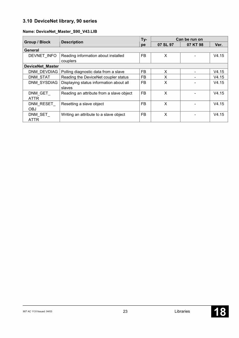
3.10 DeviceNet library, 90 series................................................................................... 23
3.11 Interbus library, 90 series ...................................................................................... 24
3.12 CANopen library, 90 series ................................................................................... 25
3.13 Ethernet library, 90 series ..................................................................................... 26
4 Conversion of 907 PC 331 blocks into 907 AC 1131, 90 series ............................. 27
4.1 Converted blocks from 907 PC 331 to 907 AC 1131, 90 series ............................ 27
4.2 Not converted 907 PC 331 blocks ......................................................................... 30
5 Index........................................................................................................................... XXXI

3907 AC 1131/Issued: 04/03 Libraries 18
1 Overview of the libraries for series 90 of 907 AC 1131
1.1 Libraries of 907 AC 1131 in versions V4.0 and V4.1
1.1.1 The libraries of 907 AC 1131 version V4.0
In version V4.0 of the software 907 AC 1131, the following libraries are included:
Name Description TypeStandard.LIB IEC standard library extern/objiecsfc.LIB IEC sequence steps internABB-BIB4.LIB ABB function block library externRCOM_V40.LIB RCOM/RCOM+ function block library extern/objCIF104.LIB Coupler basic routines library externPROFI_40.LIB PROFIBUS library intern
1.1.2 The libraries of 907 AC 1131 as of version V4.1
In order to get version V4.1, the libraries of the software were reworked and renamed. Fordistinction between the 40..50 series and the 90 series, the libraries for the 40..50 series aremarked with 'S40' and the libraries for 90 series are marked with 'S90'. In addition, the softwareversion of the library is inserted, here 'V41'. If the library is modified, these version identifiers willalso be changed.
Furthermore, subject-oriented libraries were set up, e.g. for ARCNET, CS31 bus, serialcommunication, etc. In these libraries, there are some new function blocks and also blocks fromthe ABB-BIB4.LIB.
Note:The ABB-BIB4.LIB library can now and in future be used for taking over projects whichwere created with 907 PC 331. Therefore, this library is still installed in the librarysubdirectory of the programming software.
For compatibility purposes, the libraries of the version 4.0 are installed into the subdirectory'Library\Library_V40'.
Note:It has to be kept in mind that function blocks must not exist twice!For example, the library ABB-BIB4.LIB cannot be used together with the libraryARCNET_S90_V41.LIB. Otherwise, the ARCNET function blocks would be existtwice.
Note:The function blocks of the ABB libraries do not run in the simulation mode. In thesimulation mode, only the operators and the function blocks of the IEC_S90_V4x.LIBdo run!

4 907 AC 1131/Issued: 04/03Libraries18
The following libraries come with version V4.1 of the 907 AC 1131 software:
Name Description TypeIEC_S90_V41.LIB IEC standard library, 90 series extern/objIECSFC_S90_V41.LIB IEC sequence steps, 90 series internBase_S90_V41.LIB Basic function block library, 90 series externRCOM_S90_V41.LIB RCOM/RCOM+ function block library, 90 series extern/objARCNET_S90_V41.LIB ARCNET function block library, 90 series externCS31_S90_V41.LIB Blocks for CS31 bus, 90 series externCOM_S90_V41.LIB Blocks for serial communication, 90 series externDatenablage_S90_V41.LIB Blocks for SMC and FLASH, 90 series externSystemInfo_S90_V41.LIB Blocks for system information, 90 series externCoupler_S90_V41.LIB Coupler basic routines library, 90 series externProfibus_S90_V41.LIB PROFIBUS function block library, 90 series intern
In the following sections you will find tables containing the function blocks of the obove mentioned libraries.
Note:The function blocks of the Coupler_S90_V41.LIB library are not described individually because the useruses them together with the library of an internal coupler (except ARCNET), e.g. PROFIBUS DP withPROFIBUS_S90_V41.LIB.
1.1.3 Comparison of the libraries of versions V4.0 and as of version V4.1
Below you find a comparison of the libraries of versions V4.0 and as of V4.1 including the mostimportant modifications.
Version V4.1 Version V4.0 Modifications in V4.1IEC_S90_V41.LIB Standard.LIB Counter blocks CTU, CTO, CTUDIECSFC_S90_V41.LIB iecsfc.LIB noneBase_S90_V41.LIB ABB-BIB4.LIB without groups ARCNET, CS31 bus, SMC, couplers, MODBUS, systemRCOM_S90_V41.LIB RCOM_V40.LIB noneARCNET_S90_V41.LIB Group ARCNET from ABB-BIB4.LIB and new blocksCS31_S90_V41.LIB Group CS31 bus from ABB-BIB4.LIBCOM_S90_V41.LIB Groups couplers and MODSUS from ABB-BIB4.LIB and new blocksDatenablage_S90_V41.LIB Group SMC from ABB-BIB4.LIB and new blocksSystemInfo_S90_V41.LIB Group system from ABB-BIB4.LIB and new blocksCoupler_S90_V41.LIB CIF104.LIB CIF104.LIB and new blocksProfibus_S90_V41.LIB PROFI_40.LIB none

5907 AC 1131/Issued: 04/03 Libraries 18
1.2 The libraries of the versions V4.2 and V4.3
In version V4.2 of the 907 AC 1131, the following libraries were added:
Name Description TypeBase_S40_V41.LIB Function block library for 40..50 series externBase_S40_V41.BIB Description file of the function blocks for S40..50ANAI4_20.LIB This library contains the function block ANAI4_20. intern
It serves for reading-in current signals with a signal rangeof 4...20 mA at an analog input, which is designed foran input signal range of 0...20 mA.The input current range of 4..20 mA is converted into theinternal number range of 0..32760.An input current of <3.6 mA is output as TRUE at theERR output (open-circuit monitoring).
PROFIBUS_S90_V42.LIB Bug-fix: internWhen the PROFIBUS coupler was used as slave, the bitNEW_PRM of the DPS_STAT function block was outputincorrectly in the structure of the STATE_BITS output.
In version V4.3 of the 907 AC 1131, the following libraries were added:
Name Description TypeDeviceNet_Master_S90_V43.LIB DeviceNet library for 90 series internInterbus_Master_S90_V43.LIB Interbus library for 90 series internPROFIBUS_Master_S90_V43.LIB Function blocks for PROFIBUS DP masters 90 series internPROFIBUS_Slave_S90_V43.LIB Function blocks for PROFIBUS DP slaves 90 series internSystemInfo_S90_V42.LIB Added function blocks: extern
HW_INFO – supplies hardware addresses of the DPRFPUEXINFO – evaluation of floating point exceptions
Base_free_S90_V41.LIB Base_S90_V41.LIB without password. Allows the user to externcreate libraries of his own.
COUNTW_S90_V41.LIB COUNTW function block – high-speed counter externFKG_S90_V41.LIB FKGx function blocks – function generator externLOOP_S90_V41.LIB Closed loop blocks 90 series externLowBase_S90_V41.LIB selected, often used function blocks derived from extern
Base_S90_V41.LIB
6 907 AC 1131/Issued: 04/03Libraries18
1.3 The libraries of the version V5.0
The version V5.0 of the 907 AC 1131 contains all libraries of the preceding versions V4.x.
In Version V5.0 of the 907 AC 1131, the following libraries were added:
Name Description TypeCoupler_S90_V50.LIB Socket functions for Ethernet added externCANopen_Master_S90_V43.LIB CANopen library 90 series internEthernet_S90_V50.LIB Ethernet library 90 series internRCOM_S90_V41.LIB/obj (dated Oct. 14, 2002) – bug-fix in the block: extern/obj
READ (data was overwritten even in case of error)
7907 AC 1131/Issued: 04/03 Libraries 18
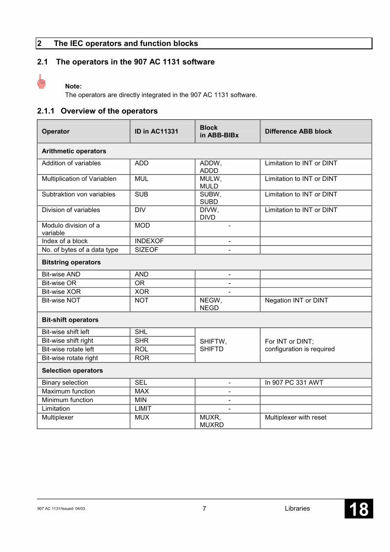
2 The IEC operators and function blocks
2.1 The operators in the 907 AC 1131 software
Note:The operators are directly integrated in the 907 AC 1131 software.
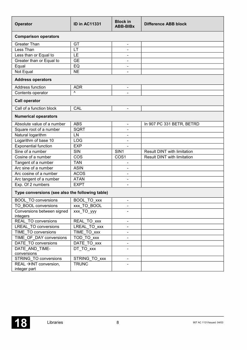
2.1.1 Overview of the operators
Operator ID in AC11331 Blockin ABB-BIBx Difference ABB block
Arithmetic operators
Addition of variables ADD ADDW,ADDD
Limitation to INT or DINT
Multiplication of Variablen MUL MULW,MULD
Limitation to INT or DINT
Subtraktion von variables SUB SUBW,SUBD
Limitation to INT or DINT
Division of variables DIV DIVW,DIVD
Limitation to INT or DINT
Modulo division of avariable
MOD -
Index of a block INDEXOF -No. of bytes of a data type SIZEOF -
Bitstring operators
Bit-wise AND AND -Bit-wise OR OR -Bit-wise XOR XOR -Bit-wise NOT NOT NEGW,
NEGDNegation INT or DINT
Bit-shift operators
Bit-wise shift left SHLBit-wise shift right SHRBit-wise rotate left ROLBit-wise rotate right ROR
SHIFTW,SHIFTD
For INT or DINT;configuration is required
Selection operators
Binary selection SEL - In 907 PC 331 AWTMaximum function MAX -Minimum function MIN -Limitation LIMIT -Multiplexer MUX MUXR,
MUXRDMultiplexer with reset
8 907 AC 1131/Issued: 04/03Libraries18
Operator ID in AC11331 Block inABB-BIBx Difference ABB block
Comparison operators
Greater Than GT -Less Than LT -Less than or Equal to LE -Greater than or Equal to GE -Equal EQ -Not Equal NE -
Address operators
Address function ADR -Contents operator ^ -
Call operator
Call of a function block CAL -
Numerical opearators
Absolute value of a number ABS - In 907 PC 331 BETR, BETRDSquare root of a number SQRT -Natural logarithm LN -Logarithm of base 10 LOG -Exponential function EXP -Sine of a number SIN SIN1 Result DINT with limitationCosine of a number COS COS1 Result DINT with limitationTangent of a number TAN -Arc sine of a number ASIN -Arc cosine of a number ACOS -Arc tangent of a number ATAN -Exp. Of 2 numbers EXPT -
Type conversions (see also the following table)
BOOL_TO conversions BOOL_TO_xxx -TO_BOOL conversions xxx_TO_BOOL -Conversions between signedintegers
xxx_TO_yyy -
REAL_TO conversions REAL_TO_xxx -LREAL_TO conversions LREAL_TO_xxx -TIME_TO conversions TIME_TO_xxx -TIME_OF_DAY conversions TOD_TO_xxx -DATE_TO conversions DATE_TO_xxx -DATE_AND_TIME-conversions
DT_TO_xxx -
STRING_TO conversions STRING_TO_xxx -REAL �INT conversion,integer part
TRUNC -
9907 AC 1131/Issued: 04/03 Libraries 18
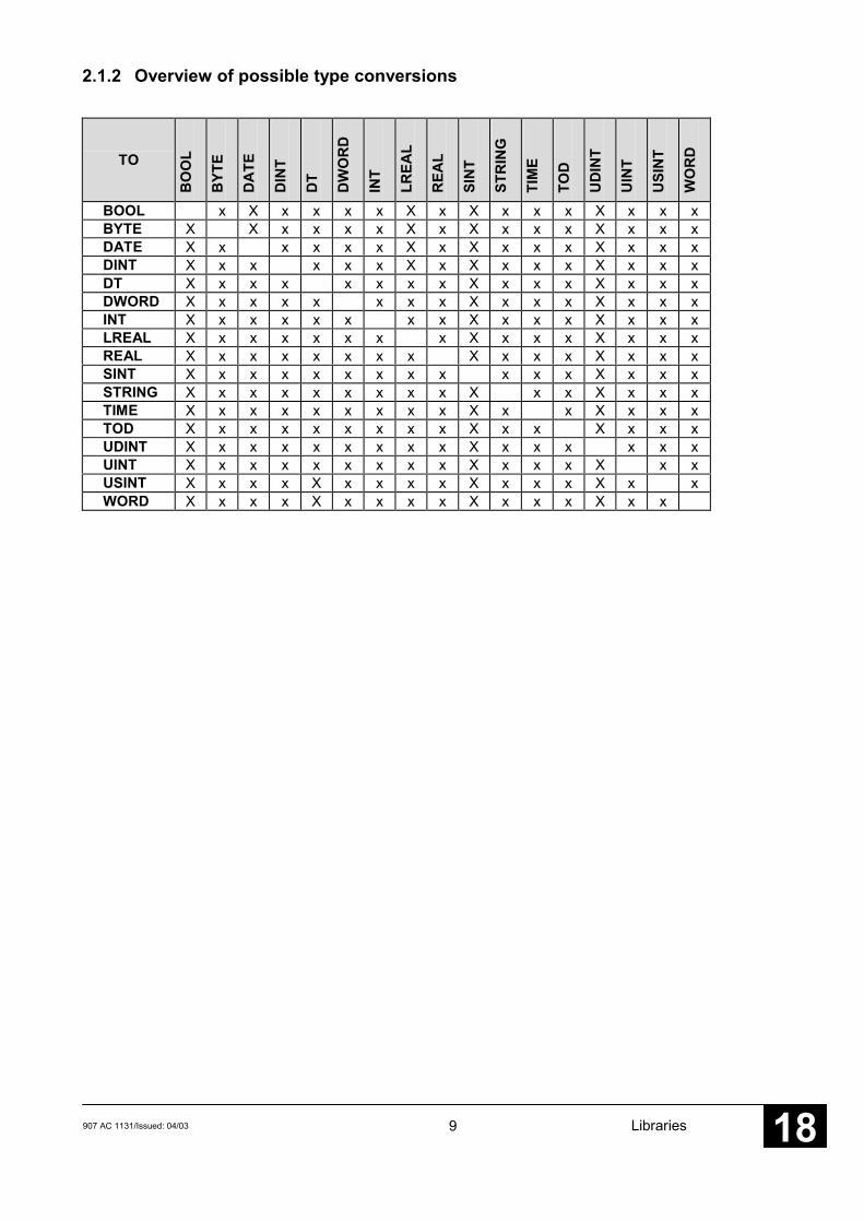
2.1.2 Overview of possible type conversions
TOB
OO
L
BYT
E
DA
TE
DIN
T
DT
DW
OR
D
INT
LREA
L
REA
L
SIN
T
STR
ING
TIM
E
TOD
UD
INT
UIN
T
USI
NT
WO
RD
BOOL x X x x x x X x X x x x X x x xBYTE X X x x x x X x X x x x X x x xDATE X x x x x x X x X x x x X x x xDINT X x x x x x X x X x x x X x x xDT X x x x x x x x X x x x X x x xDWORD X x x x x x x x X x x x X x x xINT X x x x x x x x X x x x X x x xLREAL X x x x x x x x X x x x X x x xREAL X x x x x x x x X x x x X x x xSINT X x x x x x x x x x x x X x x xSTRING X x x x x x x x x X x x X x x xTIME X x x x x x x x x X x x X x x xTOD X x x x x x x x x X x x X x x xUDINT X x x x x x x x x X x x x x x xUINT X x x x x x x x x X x x x X x xUSINT X x x x X x x x x X x x x X x xWORD X x x x X x x x x X x x x X x x
10 907 AC 1131/Issued: 04/03Libraries18
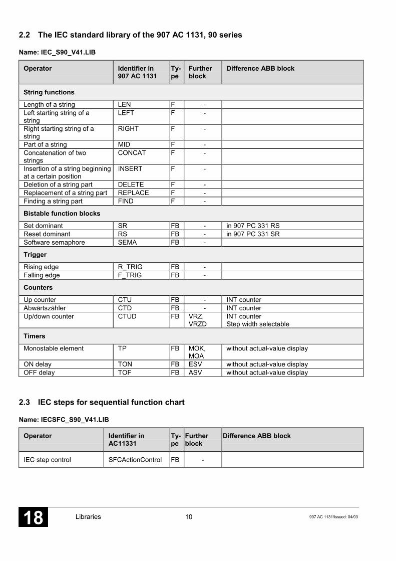
2.2 The IEC standard library of the 907 AC 1131, 90 series
Name: IEC_S90_V41.LIB
Operator Identifier in907 AC 1131
Ty-pe
Furtherblock
Difference ABB block
String functions
Length of a string LEN F -Left starting string of astring
LEFT F -
Right starting string of astring
RIGHT F -
Part of a string MID F -Concatenation of twostrings
CONCAT F -
Insertion of a string beginningat a certain position
INSERT F -
Deletion of a string part DELETE F -Replacement of a string part REPLACE F -Finding a string part FIND F -
Bistable function blocks
Set dominant SR FB - in 907 PC 331 RSReset dominant RS FB - in 907 PC 331 SRSoftware semaphore SEMA FB -
Trigger
Rising edge R_TRIG FB -Falling edge F_TRIG FB -
Counters
Up counter CTU FB - INT counterAbwärtszähler CTD FB - INT counterUp/down counter CTUD FB VRZ,
VRZDINT counterStep width selectable
Timers
Monostable element TP FB MOK,MOA
without actual-value display
ON delay TON FB ESV without actual-value displayOFF delay TOF FB ASV without actual-value display
2.3 IEC steps for sequential function chart
Name: IECSFC_S90_V41.LIB
Operator Identifier inAC11331
Ty-pe
Furtherblock
Difference ABB block
IEC step control SFCActionControl FB -

11907 AC 1131/Issued: 04/03 Libraries 18
3 Function block libraries of the 90 series
3.1 Base function block library 90 series
3.1.1 Base library with all function blocks
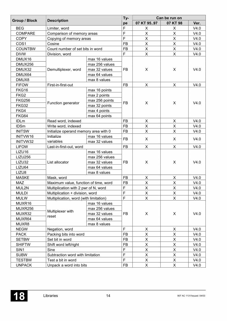
Name: Base_S90_V41.LIB
Can be run onGroup / Block Description Ty-pe 07 KT 95..97 07 KT 98 Ver.
Binary operationsBITSU Bit searcher (set bit) FB X X V4.0BMELD127 max 127 valuesBMELD16 max 16 valuesBMELD32 max 32 valuesBMELD64 max 64 valuesBMELD8
Binary value changeannunciator
max 8 values
FB X X V4.0
FIFOB First-in-first-out for bit operands FB X X V4.0IDLB Read binary variable, indexed FB X X V4.0IDSB Write binary variable, indexed FB X X V4.0INITSINITSB
Initialize operand memory area withFALSE FB X X V4.0
INITVB16 max 16 bitsINITVB32
Initializevariables max 32 bits
FB X X V4.0
LDT Illumination pushbutton control FB X X V4.0LIFOB Last-in-first-out for bit operands FB X X V4.0LZB Run number block FB X X V4.0MAJ Majority / Bit F X X V4.0
Doubleword operationsADDD Addition double word FB X X V4.0AMELDD16 max 16 valuesAMELDD32 max 32 valuesAMELDD63 max 63 valuesAMELDD8
Analog valuechange annunciator,double word
max 8 values
FB X X V4.0
BEGD Limiter, double word F X X V4.0COUNTBD Count set bits in double word FB X X V4.0DIVD Division double word FB X X V4.0DMUXD16 max 16 valuesDMUXD256 max 256 valuesDMUXD32 max 32 valuesDMUXD64 max 64 valuesDMUXD8
Demultiplexer,double word
max 8 values
FB X X V4.0
DWAES Write double word when value changes FB X X V4.0DWOL Read double word with enable FB X X V4.0DWOS Write double word with enable FB X X V4.0DWUMC16 max 16 valuesDWUMC256 max 256 valuesDWUMC32 max 32 valuesDWUMC64 max 64 valuesDWUMC8
Double wordrecoder
max 8 values
FB X X V4.0

12 907 AC 1131/Issued: 04/03Libraries18
INITSD Initialize operand memory area with TRUE(double word area)
FB X X V4.0

13907 AC 1131/Issued: 04/03 Libraries 18
Can be run onGroup / Block Description Ty-pe 07 KT 95..97 07 KT 98 Ver.
MASKED Mask, double word FB X X V4.0MAZD Maximum value, function of time,
double wordFB X X V4.0
MUL2ND Multiplication with 2 pwr of N, double word F X X V4.0MULD Multiplication, double word FB X X V4.0MUXRD16 max 16 valuesMUXRD256 max 256 valuesMUXRD32 max 32 valuesMUXRD64 max 64 valuesMUXRD8
Multiplexer withRESET,double word
max 8 values
FB X X V4.0
NEGD Negation, double word F X X V4.0PACKD Packing bits in double word FB X X V4.0SETBD Set binary value in double word FB X X V4.0SHIFTD Shift double word left/right FB X X V4.0SUBD Subtraction, double word FB X X V4.0TESTBD Test bit in double word F X X V4.0UNPACKD Unpack double word into bits FB X X V4.0USTD Switch-over gate, double word FB X X V4.0USTRD Switch-over gate with reset, double word FB X X V4.0
ConversionsBCDDUAL Conversion BCD-DUAL, word F X X V4.0BCDDUALD Conversion BCD-DUAL, double word F X X V4.0DUALBCD Conversion DUAL-BCD, word F X X V4.0DUALBCDD Conversion DUAL-BCD, double word F X X V4.0DW2W Double word�2 words FB X X V4.0DWW Double word to word conversion FB X X V4.0W2WDW 2 words � double word F X X V4.0WDW Word to double word conversion F X X V4.0
Loop controlDT1 Differenciator with delay FB X X V4.02HLG Ramp-function generator FB X X V4.02INTK Integrator FB X X V4.02PI Proportional-integral controller FB X X V4.02PIDT1 PIDT1 controller FB X X V4.02PT1 PT1 element (1st order) FB X X V4.02VGL3P Comparator with 3-point response, word FB X X V4.02VGLEH Comparator with unilateral hysteresis FB X X V4.02VGLUH Comparator with asymmetrical hysteresis FB X X V4.02
Word operationsADDW Addition, word F X X V4.0ADRWA16 max 16 valuesADRWA8 max 8 valuesADRWA127
Address selectionmax 127 values
FB X X V4.0
AMELD127 Max 127 valuesAMELD16 Max 16 valuesAMELD32 Max 32 valuesAMELD8
Analog valuechange annunciator
Max 8 values
FB X X V4.0
AMW Selection multiplexer F X X V4.0
14 907 AC 1131/Issued: 04/03Libraries18
Can be run onGroup / Block Description Ty-pe 07 KT 95..97 07 KT 98 Ver.
BEG Limiter, word F X X V4.0COMPARE Comparison of memory areas F X X V4.0COPY Copying of memory areas F X X V4.0COS1 Cosine FB X X V4.0COUNTBW Count number of set bits in word FB X X V4.0DIVW Division, word F X X V4.0DMUX16 max 16 valuesDMUX256 max 256 valuesDMUX32 max 32 valuesDMUX64 max 64 valuesDMUX8
Demultiplexer, word
max 8 values
FB X X V4.0
FIFOW First-in-first-out FB X X V4.0FKG16 max 16 pointsFKG2 max 2 pointsFKG256 max 256 pointsFKG32 max 32 pointsFKG4 max 4 pointsFKG64
Function generator
max 64 points
FB X X V4.0
IDLm Read word, indexed FB X X V4.0IDSm Write word, indexed FB X X V4.0INITSW Initialize operand memory area with 0 FB X X V4.0INITVW16 max 16 valuesINITVW32
Initializevariables max 32 values FB X X V4.0
LIFOW Last-in-first-out, word FB X X V4.0LIZU16 max 16 valuesLIZU256 max 256 valuesLIZU32 max 32 valuesLIZU64 max 64 valuesLIZU8
List allocator
max 8 values
FB X X V4.0
MASKE Mask, word FB X X V4.0MAZ Maximum value, function of time, word FB X X V4.0MUL2N Multiplication with 2 pwr of N, word F X X V4.0MULDI Multiplication + division, word F X X V4.0MULW Multiplication, word (with limitation) F X X V4.0MUXR16 max 16 valuesMUXR256 max 256 valuesMUXR32 max 32 valuesMUXR64 max 64 valuesMUXR8
Multiplexer withreset
max 8 values
FB X X V4.0
NEGW Negation, word F X X V4.0PACK Packing bits into word FB X X V4.0SETBW Set bit in word FB X X V4.0SHIFTW Shift word left/right FB X X V4.0SIN1 Sine F X X V4.0SUBW Subtraction word with limitation F X X V4.0TESTBW Test a bit in word F X X V4.0UNPACK Unpack a word into bits FB X X V4.0

15907 AC 1131/Issued: 04/03 Libraries 18
Can be run onGroup / Block Description Ty-pe 07 KT 95..97 07 KT 98 Ver.
USM Switch-over MUX (to ADRWA) F X X V4.0UST Switch-over gate, word FB X X V4.0USTR Switch-over gate with reset, word FB X X V4.0WAES Write word when value changes FB X X V4.0WDEC16 max 16 valuesWDEC256 max 256 valuesWDEC32 max 32 valuesWDEC64 max 64 valuesWDEC8
Wort decoder
max 8 values
FB X X V4.0
WOL Read word with enable F X X V4.0WOS Write word with enable F X X V4.0WUMC16 max 16 valuesWUMC256 max 256 valuesWUMC32 max 32 valuesWUMC64 max 64 valuesWUMC8
Word recoder
max 8 values
FB X X V4.0
TimersASV OFF delay FB X X V4.0ESV ON delay FB X X V4.0MOA Monostable element „abort“ FB X X V4.0MOK Monostable element „constant“ FB X X V4.0PDM Pulse duration modulator FB X X V4.0UHR Display/set real-time clock FB X X V4.0VVZ Variable delay element FB X X V4.0
CountersCOUNTW High-speed counter FB X X V4.0VRZ Up/dowm counter, word FB X X V4.0VRZD Up/down counter, double word FB X X V4.0

16 907 AC 1131/Issued: 04/03Libraries18
3.1.2 Generation of own libraries from Base_free_S90_V41.LIB
As of version 4.3 of the 907 AC 1131 software, the Base_free_S90_V41.LIB library is providedin addition to the Base_S90_V41.LIB library. This library contains all the function blocks of theBase_S90_V41.LIB library, but it is not protected by a password. This allows the user to arrangelibraries of his own.
Using the Base_free_S90_V41-LIB library, the user can arrange a library of his own by thefollowing steps:1. Open the library with:- "File"=>"Open" with: File type=Library (*.lib) and File name=Base_free_S90_V41.LIB2. Delete all function blocks and subdirectories, which are not necessary, with:- Select Block/Directory, right mouse button and then "Delete object"3. Under "Ressources"=>"Control system configuration", a CPU 90 series is entered4. Under "Project"=>"Options"=>"Translation options", a 2 is entered under the number of datasegments5. Translate project with <F11>.The warning: "This expression does not contain an allocation. No code is generated." is outputfor each function block.In version V4.3, the following error, which could be ignored, was output: "Project does notcontain any PLC_PRG function block".6. Save library with:- "File"=>"Save as..." with File type=External library and File name: Name_given_by_you7. Close library with:- "File"=>"Close"In version V4.3, the prompt for “Save changes” must be answered with “No”. In version V5.0,this prompt does not appear.
Note:It is not possible to insert new function blocks (or user-defined ones) in the library. Thereason is that the library is an external one and the code of the function blocks isstored in the run-time system of the PLC. This is why the function blocks are notprocessed in the simulation mode.
3.1.3 Libraries generated from Base_S90_V41.LIB
As of version V4.3, the following subject-oriented libraries are provided, generated from theBase_S90_V41.LIB library:
Name DescriptionCOUNTW_S90_V41.LIB COUNTW function block – high-speed counterFKG_S90_V41.LIB FKGx function blocks – function generatorLOOP_S90_V41.LIB Loop control function blocks 90 seriesLowBase_S90_V41.LIB selected, often used function blocks from
Base_S90_V41.LIB:Conversions: DW2W, W2WDWDouble word operations: DMUXD16, DMUXD8, PACKD, UNPACKDTimers: UHR, VVZWord operations: COMPARE, COPY, DMUX16, DMUX8,
PACK, UNPACK

17907 AC 1131/Issued: 04/03 Libraries 18
3.2 RCOM/RCOM+ function block library, 90 series
Name: RCOM_S90_V41.LIB
Can be run onGroup / Block Description Ty-pe 07 KT 95..97 07 KT 98 Ver.
RCOM communicationCLOCK Set clock FB X X V4.0COLDST Cold start FB X X V4.0DIAL Dial communication partner FB X X V4.0HANGUP Hang-up telephone FB X X V4.0NORMAL Normalization FB X X V4.0POLL Perform event poll FB X X V4.0RCOM Initialize 07 KP 90 R303 for RCOM
protocolFB X X V4.0
RCOM_PL Initialize 07 KP 93 R303 for RCOM+ -protocol
FB X X V4.0
READ Read data from RCOM slave FB X X V4.0READ_S Provide data for READ task FB X X V4.0RECV Receive data from the RCOM partner FB X X V4.0SYS_S RCOM system services FB X X V4.0TRANSM Send data to the RCOM partner FB X X V4.0WARMST Warm start FB X X V4.0
3.3 ARCNET function block library, 90 series
Name: ARCNET_S90_V41.LIB
Can be run onGroup / Block Description Ty-pe 07 KT 97 07 KT 98 Ver.
ARCNETAINIT ARCNET initialization FB X X V4.0AREC ARCNET data reception FB X X V4.0ASEND1 1 node FB X X V4.0ASEND16 max. 16 nodes FB X X V4.0ASEND4
Send ARCNETdata to
max. 4 nodes FB X X V4.0ASENDB Send ARCNET data, bytes to 1 node FB X X V4.0
ARCNET 5F communication_5F_ARC97 Driver for 5F-ARCNET protocols FB X X V4.05
ARCNET newAINIT_V Initialization of ARCNET coupler FB X X V4.03AREC_V Receive ARCNET data packages FB X X V4.03ASEND_V Send ARCNET data packages to
aparticipantFB X X V4.03
ASTO_V Read ARCNET timeout data packages FB X X V4.03
18 907 AC 1131/Issued: 04/03Libraries18
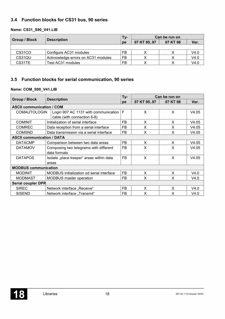
3.4 Function blocks for CS31 bus, 90 series
Name: CS31_S90_V41.LIB
Can be run onGroup / Block Description Ty-pe 07 KT 95..97 07 KT 98 Ver.
CS31CO Configure AC31 modules FB X X V4.0CS31QU Acknowledge errors on AC31 modules FB X X V4.0CS31TE Test AC31 modules FB X X V4.0
3.5 Function blocks for serial communication, 90 series
Name: COM_S90_V41.LIB
Can be run onGroup / Block Description Ty-pe 07 KT 95..97 07 KT 98 Ver.
ASCII communication / COMCOMAUTOLOGIN Login 907 AC 1131 with communication
cable (with connection 6-8)F X X V4.05
COMINIT Initialization of serial interface FB X X V4.05COMREC Data reception from a serial interface FB X X V4.05COMSND Data transmission via a serial interface FB X X V4.05
ASCII communication / DATADATACMP Comparison between two data areas FB X X V4.05DATAMOV Composing two telegrams with different
data formatsFB X X V4.05
DATAPOS Isolate „place keeper“ areas within dataareas
FB X X V4.05
MODBUS communicationMODINIT MODBUS initialization od serial interface FB X X V4.0MODMAST MODBUS master operation FB X X V4.0
Serial coupler DPRSIREC Network interface „Receive“ FB X X V4.0SISEND Network interface „Transmit“ FB X X V4.0

19907 AC 1131/Issued: 04/03 Libraries 18
3.6 Function blocks for SMC and FLASH, 90 series
Name: Datenablage_S90_V41.LIB
Can be run onGroup / Block Description Ty-pe 07 KT 95..97 07 KT 98 Ver.
FCPFDEL Delete segment in FLASH FB - X V4.1FRD Read data set from FLASH FB - X V4.1FWR Write data set into FLASH FB - X V4.1
SMCFCDEL Delete SmartMedia Card FB X X V4.0FCINIT Initialize SmartMedia Card FB X X V4.0FCRD Read data from SmartMedia Card FB X X V4.0FCWR Write data to SmartMedia Card FB X X V4.0
3.7 Function blocks for system information, 90 series
Name: SystemInfo_S90_V41.LIB
Can be run onGroup / Block Description Ty-pe 07 KT 95..97 07 KT 98 Ver.
System informationGET_STACKINFO Information about stack FB X X V4.05HEAP_INFO Information about HEAP FB X X V4.0IDENT PLC identification FB X X V4.0Projektinfo Information about the user program FB X X V4.05SYS_TIME Read system time F X X V4.0
Name: SystemInfo_S90_V42.LIB
Can be run onGroup / Block Description Ty-pe 07 KT 95..97 07 KT 98 Ver.
System informationGET_STACKINFO Information about stack FB X X V4.05HEAP_INFO Information about HEAP FB X X V4.0IDENT PLC identification FB X X V4.0Projektinfo Information about the user program FB X X V4.05SYS_TIME Read system time F X X V4.0HW_INFO Supplies the start addresses of the DPR FB X X V4.15FPUEXINFO Info about floating-point exceptions FB X X V4.16
20 907 AC 1131/Issued: 04/03Libraries18
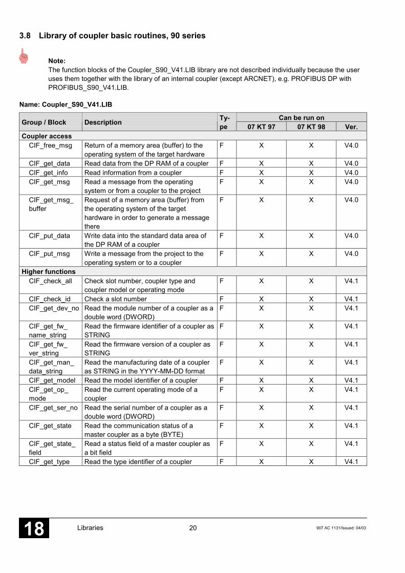
3.8 Library of coupler basic routines, 90 series
Note:The function blocks of the Coupler_S90_V41.LIB library are not described individually because the useruses them together with the library of an internal coupler (except ARCNET), e.g. PROFIBUS DP withPROFIBUS_S90_V41.LIB.
Name: Coupler_S90_V41.LIB
Can be run onGroup / Block Description Ty-pe 07 KT 97 07 KT 98 Ver.
Coupler accessCIF_free_msg Return of a memory area (buffer) to the
operating system of the target hardwareF X X V4.0
CIF_get_data Read data from the DP RAM of a coupler F X X V4.0CIF_get_info Read information from a coupler F X X V4.0CIF_get_msg Read a message from the operating
system or from a coupler to the projectF X X V4.0
CIF_get_msg_buffer
Request of a memory area (buffer) fromthe operating system of the targethardware in order to generate a messagethere
F X X V4.0
CIF_put_data Write data into the standard data area ofthe DP RAM of a coupler
F X X V4.0
CIF_put_msg Write a message from the project to theoperating system or to a coupler
F X X V4.0
Higher functionsCIF_check_all Check slot number, coupler type and
coupler model or operating modeF X X V4.1
CIF_check_id Check a slot number F X X V4.1CIF_get_dev_no Read the module number of a coupler as a
double word (DWORD)F X X V4.1
CIF_get_fw_name_string
Read the firmware identifier of a coupler asSTRING
F X X V4.1
CIF_get_fw_ver_string
Read the firmware version of a coupler asSTRING
F X X V4.1
CIF_get_man_data_string
Read the manufacturing date of a coupleras STRING in the YYYY-MM-DD format
F X X V4.1
CIF_get_model Read the model identifier of a coupler F X X V4.1CIF_get_op_mode
Read the current operating mode of acoupler
F X X V4.1
CIF_get_ser_no Read the serial number of a coupler as adouble word (DWORD)
F X X V4.1
CIF_get_state Read the communication status of amaster coupler as a byte (BYTE)
F X X V4.1
CIF_get_state_field
Read a status field of a master coupler asa bit field
F X X V4.1
CIF_get_type Read the type identifier of a coupler F X X V4.1

21907 AC 1131/Issued: 04/03 Libraries 18
Name: Coupler_S90_V50.LIB
Can be run onGroup / Block Description Ty-pe 07 KT 97 07 KT 98 Ver.
Coupler accesssee Coupler_S90_V41.LIB V4.1
Higher functionssee Coupler_S90_V41.LIB V4.1
Socket accessCIF_ETH_free_socket
Enable resources of a socket F X X V5.0
CIF_ETH_get_socket
Request resources for a new socket F X X V5.0
CIF_ETH_socket_buffer_handler
Create/enable protocol-specific buffersof a socket or poll informationabout/from them
F X X V5.0
CIF_ETH_socket_handler
Execute operations on a sockete.g. Open, Connect, Send,Receive, Close, Get/Set options
F X X V5.0
CIF_ETH_socket_info
Request informationen about a socket F X X V5.0
CIF_ETH_socket_options_handler
Perform/poll protocol-specific settingsof a socket
F X X V5.0

22 907 AC 1131/Issued: 04/03Libraries18
3.9 PROFIBUS library, 90 series
3.9.1 PROFIBUS library, 90 series in versions V4.1 and V4.2
Name: PROFIBUS_S90_V41.LIB
Can be run onGroup / Block Description Ty-pe 07 KT 97 07 KT 98 Ver.
InformationPROFI_INFO Read coupler information FB X X V4.0
DP master blocksDPM_STAT Read coupler status FB X X V4.0DPM_SLVDIAG Read detailed PROFIBUS diagnosis data
from a slaveFB X X V4.0
DPM_SYSDIAG Read system diagnosis data FB X X V4.0DP slave blocks
DPS_STAT Read the coupler status FB X X V4.0
3.9.2 PROFIBUS library, 90 series as of version V4.3
Name: PROFIBUS_Master_S90_V43.LIB
Can be run onGroup / Block Description Ty-pe 07 KT 97 07 KT 98 Ver.
GeneralPROFI_INFO Read coupler information FB X X V4.0
Status / DiagnosisDPM_STAT Read the coupler status FB X X V4.0DPM_SLVDIAG Read detailed PROFIBUS diagnosis from
a slaveFB X X V4.0
DPM_SYSDIAG Read system diagnosis FB X X V4.0Control
DPM_CTRL Send control commands to DP slaves FB X X V4.0Parameters
DPM_SETPRM Send user parameters to a DP slaveduring runtime
FB X X V4.0
Acyclic read of I/O dataDPM_READ_INPUT
Read input data from a slave not assignedto the master
FB X X V4.0
DPM_READ_OUTPUT
Read output data from a slave notassigned to the master
FB X X V4.0
Name: PROFIBUS_Slave_S90_V43.LIB
Can be run onGroup / Block Description Ty-pe 07 KT 97 07 KT 98 Ver.
Status / DiagnosisDPS_STAT Read coupler status FB X X V4.0DPS_EXTDIAG Send error flags of the basic unit as
extended diagnosisFB X X V4.0
ParametersDPS_GETPRM Read user parameters FB X X V4.0
23907 AC 1131/Issued: 04/03 Libraries 18
3.10 DeviceNet library, 90 series
Name: DeviceNet_Master_S90_V43.LIB
Can be run onGroup / Block Description Ty-pe 07 SL 97 07 KT 98 Ver.
GeneralDEVNET_INFO Reading information about installed
couplersFB X - V4.15
DeviceNet_MasterDNM_DEVDIAG Polling diagnostic data from a slave FB X - V4.15DNM_STAT Reading the DeviceNet coupler status FB X - V4.15DNM_SYSDIAG Displaying status information about all
slavesFB X - V4.15
DNM_GET_ATTR
Reading an attribute from a slave object FB X - V4.15
DNM_RESET_OBJ
Resetting a slave object FB X - V4.15
DNM_SET_ATTR
Writing an attribute to a slave object FB X - V4.15

24 907 AC 1131/Issued: 04/03Libraries18
3.11 Interbus library, 90 series
Name: Interbus_Master_S90_V43.LIB
Can be run onGroup / Block Description Ty-pe 07 KT 97 07 KT 98 Ver.
GeneralINTERBUS_INFO
Read information from couplers installed FB - X V4.16
Interbus master / diagnosisIBM_DEVDIAG Poll diagnostic data from a slave FB - X V4.16IBM_STAT Read status from the Interbus coupler FB - X V4.16IBM_SYSDIAG Display status overview of all slaves FB - X V4.16
Interbus master / PCPIBM_GET_OD Read object descriptions from a PCP-
supporting slaveFB - X V4.16
IBM_READ Read parameters from a PCP-supportingslave
FB - X V4.16
IBM_READ_EN Enable reading parameters from thecontrol system by a PCP-supporting slave
FB - X V4.16
IBM_WRITE Write parameters to a PCP-supportingslave
FB - X V4.16
IBM_WRITE_EN
Enable writing parameters to the controlsystem by a PCP-supporting slave
FB - X V4.16

25907 AC 1131/Issued: 04/03 Libraries 18
3.12 CANopen library, 90 series
Name: CANopen_Master_S90_V43.LIB
Can be run onGroup / Block Description Ty-pe 07 KT 97 07 KT 98 Ver.
GeneralCANopen_INFO Reading information about the installed
couplersFB X X V5.0
CAN 2.0 A \ Help functionsIDENT_CAN2A_TO_WORD
Generating a general CAN telegramheader according to CAN 2.0 A
F X X V5.0
IDENT_CANopen_TO_WORD
Generating a CANopen-specific CANtelegram header according to CAN 2.0 A
F X X V5.0
WORD_TO_IDENT_CAN2A
Splitting a general CAN telegram headeraccording to CAN 2.0 A
F X X V5.0
WORD_TO_IDENT_CANopen
Splitting a CANopen-specific CANtelegram header according to CAN 2.0 A
F X X V5.0
CAN 2.0 ACAN_REC_2A Receiving CAN telegrams with 11 bit
identifiers according to CAN 2.0 AFB X X V5.0
CAN_REC_FILTER_2A
Enabling of identifiers for receiving CANtelegrams with 11 bit identifiers accordingto CAN 2.0 A
FB X X V5.0
CAN_SEND_2A Transmitting CAN telegrams with 11 bitidentifiers according to CAN 2.0 A
FB X X V5.0
CAN 2.0 BCAN_REC_2B Receiving CAN telegrams with 29 bit
identifiers according to CAN 2.0 BFB X X V5.0
CAN_SEND_2B Transmitting CAN telegrams with 29 bitidentifiers according to CAN 2.0 B
FB X X V5.0
CANopen Master \ NMTCANoM_NMT Controlling NMT node states via network
managementFB X X V5.0
CANopen Master \ SDOCANoM_SDO_READ
Reading an object from a slave FB X X V5.0
CANoM_SDO_WRITE
Writing an object to a slave FB X X V5.0
CANopen Master \ Status/DiagnosisCANoM_NODEDIAG
Polling diagnostic data from a slave FB X X V5.0
CANoM_RES_ERR
Resetting the coupler’s error indications FB X X V5.0
CANoM_STAT Reading the CANopen coupler status FB X X V5.0CANoM_SYSDIAG
Reading a status survey of all slaves FB X X V5.0

26 907 AC 1131/Issued: 04/03Libraries18
3.13 Ethernet library, 90 series
Name: Ethernet_S90_V50.LIB
Can be run onGroup / Block Description Ty-pe 07 KT 97 07 KT 98 Ver.
GeneralETH_Info Reading information about the installed
couplersFB X X V5.x
MODBUS_TCPETH_MODMAST Processing Open MODBUS on TCP/IP
client telegramsFB X X V5.0
ETH_MODSTAT Open MODBUS processing FB X X V5.0UDP_IP
ETH_AINIT Initializing the Ethernet UDP/IP dataexchange
FB X X V5.0
ETH_AREC Reading an Ethernet UDP/IP datapackage from the receive buffer
FB X X V5.0
ETH_ASEND Transmitting an Ethernet UDP/IP datapackage
FB X X V5.0
ETH_ASTO Reading Ethernet UDP/IP timeout datapackages
FB X X V5.0

27907 AC 1131/Issued: 04/03 Libraries 18
4 Conversion of 907 PC 331 blocks into 907 AC 1131, 90 series
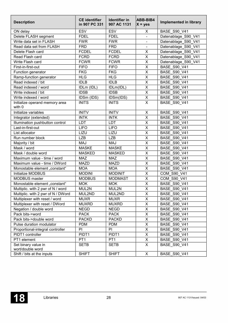
4.1 Converted blocks from 907 PC 331 to 907 AC 1131, 90 series
Description CE identifierin 907 PC 331
Identifier in907 AC 1131
ABB-BIB4X = yes Implemented in library
Subtraction / word - SUBW X BASE_S90_V41Multiplication / word * MULW X BASE_S90_V41Multiplication + division / word *: (MULDI) MULDI X BASE_S90_V41Multiplication / double word *D (MULD) MULD X BASE_S90_V41Division / word : DIVW X BASE_S90_V41Division / double word :D (DIVD) DIVD X BASE_S90_V41Addition / word + ADDW X BASE_S90_V41Addition / double word +D ADDD X BASE_S90_V412 words -> double word 2WDW W2WDW X BASE_S90_V41Address selection ADRWA ADRWA X BASE_S90_V41ARCNET initialization AINIT AINIT X ARCNET_S90_V41Analog value change annunciator AMELD AMELD X BASE_S90_V41Analog v. ch. Ann. / double word AMELDD AMELDD X BASE_S90_V41ARCNET data reception AREC AREC X ARCNET_S90_V41ARCNET data transmission ASEND ASEND X ARCNET_S90_V41OFF delay ASV ASV X BASE_S90_V41Selection multiplexer AWM AWM X BASE_S90_V41BCD->DUAL conversion / word BCDDUAL BCDDUAL X BASE_S90_V41BCD->DUAL conv. / double word BCDDUALD BCDDUALD X BASE_S90_V41Limiter / word BEG BEG X BASE_S90_V41Limiter / double word BEGD BEGD X BASE_S90_V41Bit searcher (set bit) BITSU BITSU X BASE_S90_V41Binary value change annunciator BMELD BMELD X BASE_S90_V41Copying memory areas COPY COPY X BASE_S90_V41Cosine COS1 COS1 X BASE_S90_V41Test number of bits inword/double word
COUNTB COUNTB X BASE_S90_V41
Configure CS31 modules CS31CO CS31CO X CS31_S90_V41Acknow. Error, CS31 modules CS31QU CS31QU X CS31_S90_V41Subtraction / double word -D (SUBD) SUBD X BASE_S90_V41Demultiplexer / word DMUX DMUX X BASE_S90_V41Demultiplexer / double word DMUXD DMUXD X BASE_S90_V41Differentiator with delay DT1 DT1 X BASE_S90_V41Dual->BCD conversion / word DUALBCD DUALBCD X BASE_S90_V41Dual->BCD conv. / double word DUALBCDD DUALBCDD X BASE_S90_V41Double word -> 2 words DW2W DW2W X BASE_S90_V41Write dword when value changes DWAES DWAES X BASE_S90_V41Read double word with enable DWOL DWOL X BASE_S90_V41Write double word with enable DWOS DWOS X BASE_S90_V41Double word recoder DWUMC DWUMC X BASE_S90_V41Double word->word conversion DWW DWW X BASE_S90_V41
28 907 AC 1131/Issued: 04/03Libraries18
Description CE identifierin 907 PC 331
Identifier in907 AC 1131
ABB-BIB4X = yes Implemented in library
ON delay ESV ESV X BASE_S90_V41Delete FLASH segment FDEL FDEL - Datenablage_S90_V41Write data set in FLASH FWR FWR - Datenablage_S90_V41Read data set from FLASH FRD FRD - Datenablage_S90_V41Delete Flash card FCDEL FCDEL X Datenablage_S90_V41Read Flash card FCRD FCRD X Datenablage_S90_V41Write Flash card FCWR FCWR X Datenablage_S90_V41First-in-first-out FIFO FIFO X BASE_S90_V41Function generator FKG FKG X BASE_S90_V41Ramp-function generator HLG HLG X BASE_S90_V41Read indexed / bit IDLB IDLB X BASE_S90_V41Read indexed / word IDLm (IDL) IDLm(IDL) X BASE_S90_V41Write indexed / bit IDSB IDSB X BASE_S90_V41Write indexed / word IDSm (IDS) IDSm(IDS) X BASE_S90_V41Initialize operand memory areawith 0
INITS INITS X BASE_S90_V41
Initialize variables INITV INITV X BASE_S90_V41Integrator (extended) INTK INTK X BASE_S90_V41Illumination pushbutton control LDT LDT X BASE_S90_V41Last-in-first-out LIFO LIFO X BASE_S90_V41List allocator LIZU LIZU X BASE_S90_V41Run number block LZB LZB X BASE_S90_V41Majority / bit MAJ MAJ X BASE_S90_V41Mask / word MASKE MASKE X BASE_S90_V41Mask / double word MASKED MASKED X BASE_S90_V41Maximum value - time / word MAZ MAZ X BASE_S90_V41Maximum value - time / DWord MAZD MAZD X BASE_S90_V41Monostable element „constant“ MOA MOA X BASE_S90_V41Initialize MODBUS MODINI MODINIT X COM_S90_V41MODBUS master MODBUS MODMAST X COM_S90_V41Monostable element „constant“ MOK MOK X BASE_S90_V41Multiplic. with 2 pwr of N / word MUL2N MUL2N X BASE_S90_V41Multiplic. with 2 pwr of N / DWord MUL2ND MUL2ND X BASE_S90_V41Multiplexer with reset / word MUXR MUXR X BASE_S90_V41Multiplexer with reset / DWord MUXRD MUXRD X BASE_S90_V41Negation / double word NEGD NEGD X BASE_S90_V41Pack bits->word PACK PACK X BASE_S90_V41Pack bits->double word PACKD PACKD X BASE_S90_V41Pulse duration modulator PDM PDM X BASE_S90_V41Proportional-integral controller PI PI X BASE_S90_V41PIDT1 controller PIDT1 PIDT1 X BASE_S90_V41PT1 element PT1 PT1 X BASE_S90_V41Set binary value inwort/double word
SETB SETB X BASE_S90_V41
Shift / bits at the inputs SHIFT SHIFT X BASE_S90_V41

29907 AC 1131/Issued: 04/03 Libraries 18
Description CE identifierin 907 PC 331
Identifier in907 AC 1131
ABB-BIB4X = yes Implemented in library
Sine SIN1 SIN1 X BASE_S90_V41Initialization of interface SINIT SINIT - COM_S90_V41Network interface, „Receive“ SIREC SIREC X COM_S90_V41Network interface, „Send“ SISEND SISEND X COM_S90_V41Test bit in word/double word TESTB TESTB X BASE_S90_V41Display/set clock UHR UHR X BASE_S90_V41Unpack word->bits UNPACK UNPACK X BASE_S90_V41Unpack double word->bits UNPACKD UNPACKD X BASE_S90_V41Switch-over MUX (to ADRWA) USM USM X BASE_S90_V41Switch-over gate / word UST UST X BASE_S90_V41Switch-over gate / double word USTD USTD X BASE_S90_V41Switch-over gate with reset / word USTR USTR X BASE_S90_V41Switch-over gate with reset / DWord USTRD USTRD X BASE_S90_V41Comparator 3-point / word VGL3P VGL3P X BASE_S90_V41Comp. unilateral hysteresis VGLEH VGLEH X BASE_S90_V41Comp. asymm. hysteresis VGLUH VGLUH X BASE_S90_V41Up/down counter / word VRZ VRZ X BASE_S90_V41Up/down counter / DWord VRZD VRZD X BASE_S90_V41Variable delay element VVZ VVZ X BASE_S90_V41Write word when value changes. WAES WAES X BASE_S90_V41Word decoder WDEC WDEC X BASE_S90_V41Conversion word->double word WDW WDW X BASE_S90_V41Read word with enable WOL WOL X BASE_S90_V41Write word with enable WOS WOS X BASE_S90_V41Word recoder WUMC WUMC X BASE_S90_V41

30 907 AC 1131/Issued: 04/03Libraries18
4.2 Not converted 907 PC 331 blocks
Description VE identifier in907 PC 331
Remarks
Conditional program end =PE Not necessaryProgram abortion ABORT -Adaption for controller ADAPT -Convert 0..20 into 4..20 ANAI4_20 - as of V 4.3: contained in library ANAI4_20.LIBData packages to ARCNET APOLL Not necessaryARCNET send extension ASEND+ Not necessaryCall C subroutine CALLC -Call Assembler subroutint CALLUP -Read direct inputs DIN -Write direct outputs DOUT -Output of ASCII characters DRUCK Replacement block in COM_S90_V41.LIBReceive ASCII characters EMASm Replacement block in COM_S90_V41.LIBAddition for EMASm EMASmVT Replacement block in COM_S90_V41.LIBError searcher with delete FEHSU -Configure process image IOCON -Read byte from I/O address IOR -Write byte to I/O address IOW -Program end PE Not necessaryRead historical value / bit RDB -Read historical value/ DWord RDDW -Read historical value/ word RDW -Error searcher with storage SFEHSU -Bit->historical value WRB -Double word>historical value WRDW -Word->historical value WRW -
31907 AC 1131/Issued: 04/03 Libraries 18
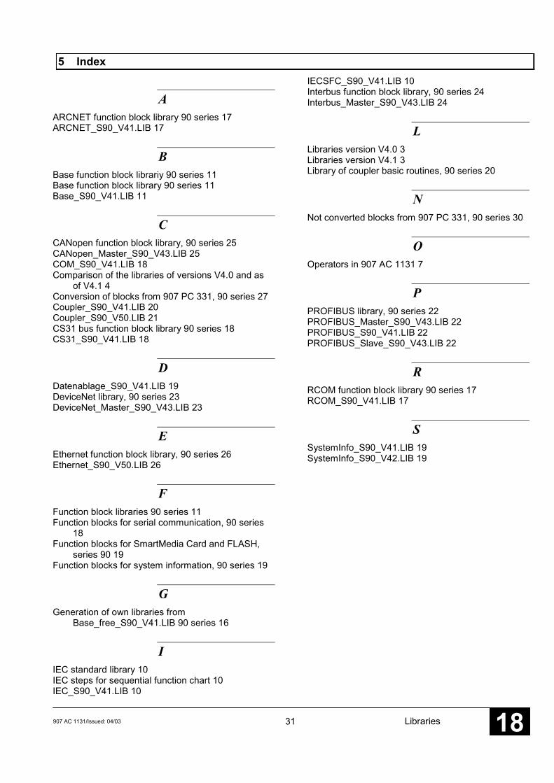
5 Index
AARCNET function block library 90 series 17ARCNET_S90_V41.LIB 17
BBase function block librariy 90 series 11Base function block library 90 series 11Base_S90_V41.LIB 11
CCANopen function block library, 90 series 25CANopen_Master_S90_V43.LIB 25COM_S90_V41.LIB 18Comparison of the libraries of versions V4.0 and as
of V4.1 4Conversion of blocks from 907 PC 331, 90 series 27Coupler_S90_V41.LIB 20Coupler_S90_V50.LIB 21CS31 bus function block library 90 series 18CS31_S90_V41.LIB 18
DDatenablage_S90_V41.LIB 19DeviceNet library, 90 series 23DeviceNet_Master_S90_V43.LIB 23
EEthernet function block library, 90 series 26Ethernet_S90_V50.LIB 26
FFunction block libraries 90 series 11Function blocks for serial communication, 90 series
18Function blocks for SmartMedia Card and FLASH,
series 90 19Function blocks for system information, 90 series 19
GGeneration of own libraries from
Base_free_S90_V41.LIB 90 series 16
IIEC standard library 10IEC steps for sequential function chart 10IEC_S90_V41.LIB 10
IECSFC_S90_V41.LIB 10Interbus function block library, 90 series 24Interbus_Master_S90_V43.LIB 24
LLibraries version V4.0 3Libraries version V4.1 3Library of coupler basic routines, 90 series 20
NNot converted blocks from 907 PC 331, 90 series 30
OOperators in 907 AC 1131 7
PPROFIBUS library, 90 series 22PROFIBUS_Master_S90_V43.LIB 22PROFIBUS_S90_V41.LIB 22PROFIBUS_Slave_S90_V43.LIB 22
RRCOM function block library 90 series 17RCOM_S90_V41.LIB 17
SSystemInfo_S90_V41.LIB 19SystemInfo_S90_V42.LIB 19

32 907 AC 1131/Issued: 04/03Libraries18
Software Description Advant Controller 31Intelligent DecentralizedAutomation System
Base Function Block Library90 Series
ABB Schalt-und Steuerungstechnik
Base90 Series


907 AC 1131/Issued: 09.03 1 Base_S90 Library 18
Contents
The Base_S90 function block library 4Special characteristics of the Base_S90 function block library ................................. 4Functions: ................................. 4Function blocks: ................................. 4Special characteristics of individual blocks: ................................. 4
Overview of blocks arranged according to their call names 6ADDITION DOUBLE WORD ADDD ..................... 11ADDITION WORD ADDW .................... 12ADDRESS SELECTION ADRWA(8..16)........ 13ANALOG VALUE CHANGE ANNUNCIATOR, WORD AMELD(8..127)....... 16ANALOG VALUE CHANGE ANNUNCIATOR, DOUBLE WORD AMELDD(8..63) ...... 18OFF DELAY ASV ........................ 20SELECTION MULTIPLEXER AWM....................... 21BCD TO DUAL CONVERSION, WORD BCDDUAL .............. 22BCD TO DUAL CONVERSION, DOUBLE WORD BCDDUALD............ 24LIMITER, WORD BEG........................ 26LIMITER, DOUBLE WORD BEGD ..................... 27BIT SEARCHER BITSU..................... 28BINARY VALUE CHANGE ANNUNCIATOR BMELD(8..127)....... 31COMPARISON OF TWO DATA BLOCKS COMPARE ............. 33COPYING MEMORY AREAS COPY ..................... 34COSINE COS1...................... 35BIT COUNTER, DOUBLE WORD COUNTBD.............. 37BIT COUNTER, WORD COUNTBW............. 38HIGH-SPEED COUNTER COUNTW ............... 39DIVISION DOUBLE WORD DIVD....................... 43DIVISION WORD DIVW ...................... 45DEMULTIPLEXER, WORD DMUX(8..256) ........ 46DEMULTIPLEXER, DOUBLE WORD DMUXD(8..256)...... 48DIFFERENTIATOR WITH DELAY OF THE 1ST ORDER DT1......................... 50DUAL TO BCD CONVERSION, WORD DUALBCD .............. 52DUAL TO BCD CONVERSION, DOUBLE WORD DUALBCDD............ 54DOUBLE WORD TO TWO WORDS CONVERSION DW2W .................... 56WRITE DOUBLE WORD IN THE EVENT OF VALUE CHANGE DWAES .................. 57READ DOUBLE WORD WITH ENABLING DWOL..................... 58WRITE DOUBLE WORD WITH ENABLING DWOS .................... 59DOUBLE WORD RECODER DWUMC(8..256)..... 60DOUBLE WORD TO WORD CONVERSION DWW ...................... 62ON DELAY ESV ........................ 63STACK MEMORY FIRST IN FIRST OUT, BINARY FIFOB..................... 64STACK MEMORY FIRST IN FIRST OUT, WORD FIFOW.................... 66FUNCTION GENERATOR FKG(2..256)............ 68RAMP FUNCTION GENERATOR HLG ........................ 70READ BINARY VARIABLE, INDEXED IDLB ....................... 74READ WORD VARIABLE, INDEXED IDLM....................... 76WRITE BINARY VARIABLE, INDEXED IDSB ....................... 78
Base_S90 Library 2 907 AC 1131/Stand: 09.0318
WRITE WORD VARIABLE, INDEXED IDSM....................... 80INITIALIZE MEMORY AREA IN THE BINARYOPERAND MEMORY WITH ZERO INITSB .................... 82INITIALIZE MEMORY AREA IN THE DOUBLE WORDOPERAND MEMORY WITH ZERO INITSD.................... 83INITIALIZE MEMORY AREA IN THE WORD OPERAND MEMORY WITH ZERO INITSW ................... 84INITIALIZE VARIABLES, BINARY INITVB(16..32)........ 85INITIALIZE VARIABLES, WORD INITVW(16..32)....... 87INTEGRATOR (EXTENDED) INTK ....................... 89ILLUMINATION PUSHBUTTON CONTROL LDT......................... 93STACK MEMORY LAST IN FIRST OUT, BINARY LIFOB ..................... 95STACK MEMORY LAST IN FIRST OUT, WORD LIFOW .................... 97LIST ALLOCATOR LIZU(8..256) ........... 99RUN NUMBER BLOCK LZB ....................... 101MAJORITY MAJ....................... 102MASK, WORD MASKE ................. 103MASK, DOUBLE WORD MASKED .............. 104MAXIMUM VALUE GENERATOR AS A FUNCTION OF TIME, WORD MAZ ...................... 105MAXIMUM VALUE GENERATOR AS A FUNCTION OF TIME, DOUBLE WORD MAZD.................... 106MONOSTABLE ELEMENT »ABORT« MOA...................... 107MONOSTABLE ELEMENT »CONSTANT« MOK...................... 108MULTIPLICATION BY 2 TO THE POWER OF N, WORD MUL2N.................. 109MULTIPLICATION BY 2 TO THE POWER OF N, DOUBLE WORD MUL2ND............... 111MULTIPLICATION, DOUBLE WORD MULD.................... 113MULTIPLICATION WITH DIVISION MULDI................... 114MULTIPLICATION, WORD MULW................... 115MULTIPLEXER WITH RESET, WORD MUXR(8..256)....... 116MULTIPLEXER WITH RESET, DOUBLE WORD MUXRD(8..256) .... 118NEGATION, DOUBLE WORD NEGD ................... 120NEGATION, WORD NEGW .................. 121PACK BINARY VARIABLES IN WORD PACK.................... 122PACK BINARY VARIABLES IN DOUBLE WORD PACKD ................. 124PULSE DURATION MODULATOR PDM...................... 126PROPORTIONAL INTEGRAL CONTROLLER PI .......................... 128PIDT1 CONTROLLER PIDT1 ................... 132PT1 ELEMENT PT1 ....................... 137SET BIT IN DOUBLE WORD SETBD.................. 139SET BIT IN WORD SETBW................. 140SHIFT BLOCK, DOUBLE WORD SHIFTD................. 141SHIFT BLOCK, WORD SHIFTW................ 144SINE 0.0 TO 360.0 DEGREES SIN1...................... 147SUBTRACTION, DOUBLE WORD SUBD.................... 149SUBTRACTION, WORD SUBW................... 150TEST BIT IN DOUBLE WORD TESTBD ............... 151TEST BIT IN WORD TESTBW............... 152DISPLAY AND SET CLOCK UHR...................... 153UNPACKING A WORD INTO BINARY VARIABLES UNPACK............... 156UNPACKING A DOUBLE WORD INTO BINARY VARIABLES UNPACKD ............ 158SWITCHOVER MULTIPLEXER USM...................... 160SWITCHOVER GATE UST ...................... 161SWITCHOVER GATE / DOUBLE WORD USTD.................... 162SWITCHOVER GATE WITH RESET USTR.................... 163SWITCHOVER GATE WITH RESET / DOUBLE WORD USTRD ................. 164COMPARATOR WITH 3-POINT RESPONSE VGL3P .................. 165COMPARATOR WITH UNILATERAL HYSTERESIS VGLEH ................. 167COMPARATOR WITH ASYMMETRICAL HYSTERESIS VGLUH ................. 169UP-DOWN COUNTER VRZ....................... 171UP-DOWN COUNTER / DOUBLE WORD VRZD.................... 173VARIABLE DELAY ELEMENT VVZ....................... 175
907 AC 1131/Issued: 09.03 3 Base_S90 Library 18
TWO WORDS INTO DOUBLE WORD CONVERSION W2WDW .............. 176WRITE WORD IN THE EVENT OF VALUE CHANGE WAES................... 177WORD DECODER WDEC(8…256) .... 178WORD TO DOUBLE WORD CONVERSION WDW .................... 180READ WORD WITH ENABLING WOL ..................... 181WRITE WORD WITH ENABLING WOS..................... 182WORD RECODER WUMC(8…256).... 183
Glossary 185
Index 187

THE BASE_S90 FUNCTION BLOCK LIBRARY
Base_S90 Library 4 907 AC 1131/Stand: 09.0318
The Base_S90 function block librarySpecial characteristics of the Base_S90function block libraryThe manufacturer's basic functions and function blocksare integrated in the Base_S90 library. These blockswere, identically in their functionality, converted fromthe well-known blocks of the 07 KT 94 EBS. However,there are some special things to keep in mind when theblocks are selected and called.
Caution:The blocks of the Base Library only run in the RUNmode of the PLC, not in the simulation mode.
Functions:The FBD blocks are identically constructed comparedto the blocks available in the previous programmingsoftware. Some input and output names have beenchanged as not all characters are allowed. In allprogramming languages the order of the inputs andoutputs is identical. The library window displays theassignment of the blocks (order and variable type).
Function blocks:A main characteristic of the function blocks is that aninstance has to be defined when calling them. In thiscase the following differences has to be observed.
1. Function blocks with historical values:
For function blocks with historical values it has to beobserved that instance names may not be definedseveral times if different data sets have to be called.
Example:
Name TypeVRZ1 VRZVRZ2 VRZ. .. .
2. Function blocks without historical values:
For function blocks without historical values only oneinstance has to be defined for the FB type. Thisinstance can be used for several calls of the FB (alsowith different I/O values).
Example:
Name TypeADDD1 ADDD (for all ADDD blocks used in
the program). .. .
but
ADDD1 ADDD (for all ADDD blocks used inthe program)
SUBD1 SUBD (for all SUBD blocks used inthe program)
. .
. .
The instance name can be defined without anyrestrictions. The type is preset and identical to thefunction block name.
Special characteristics of individual blocks:1) Negation of inputs and outputs:
In the 907 AC 1131 the negation of inputs andoutputs is only possible for bit operands (variabletypes: BOOL, BYTE, WORD, DWORD). The knownoperands word flag %MW (MW) and double wordflag %MD (MD) are of the variable type INT andDINT. Negating of these variables is only possiblewith the blocks NEGW and NEGD.
2) Duplication of inputs:
Blocks: ADDW, DIVW, MULW, SUBW
The duplication of the inputs is performed by linkingtogether several functions.
In addition the operators (ADD, DIV, MUL, SUB) canbe used and duplicated as often as required. Butthese IEC blocks do not have a limitation.
3) Duplication of inputs and outputs:
Blocks: e.g. PACK, PACKD, UNPACK, UNPACKD
In the FBD editor the number of duplications isinquired when entering the data. Input n is assignedaccordingly and the block is displayed.

THE BASE_S90 FUNCTION BLOCK LIBRARY
907 AC 1131/Issued: 09.03 5 Base_S90 Library 18
4) Different data types:
Blocks: SHIFTW, SHIFTD
The SHIFT block available in the 907 PC 331 canprocess word as well as double word variables. Thisfunctionality was divided into two blocks:
SHIFTW … Shift word variableSHIFTD … Shift double word variable
Due to the division the switchover inputWORD/DOUBLEWORD was removed.
5) Special solutions:
Blocks: FKG2, FKG4, FKG16, FKG32, FKG256
According to the number of points the FKG block isselected. The number assigned to FKG representsthe maximum number of available points. At input nthe real number of points is indicated. Not usedpoints do not have to be assigned.
Example:– 7 points are required
i.e. FKG16 must be selectedn = 7the inputs XC0/YC0…XC6/YC6 are assigned.
Blocks: WUMC8, WUMC16, WUMC32,WUMC64, WUMC256
According to the number of comparison parametersthe WUMC block is selected. The number assignedto WUMC represents the maximum number ofavailable comparison parameters. At input n the realnumber of comparison parameters is indicated. Notused inputs do not have to be assigned.
Example:– 10 comparison parameters are required
i.e. WUMC16 must be selectedn = 10the inputs EC0/AC0…EC9/AC9 are assigned
Blocks: WDEC8, WDEC16, WDEC32,WDEC64, WDEC256
According to the number of comparison parametersthe WDEC block is selected. The number assignedto WDEC represents the maximum number ofavailable comparison parameters. At input n the realnumber of comparison parameters is indicated. Notused inputs do not have to be assigned.
Example:– 10 comparison parameters are required
i.e. WDEC16 must be selectedn = 10the inputs EC0…EC9 are assigned

OVERVIEW OF BLOCKS ARRANGED ACCORDING TO THEIR CALL NAMES
Base_S90 Library 6 907 AC 1131/Stand: 09.0318
Overview of blocks arranged according to their call names
Character description:
FBmV … Function block with historical values
FBoV … Function block without historical values
F … Function
CE Name Type Function Page
ADDD FBoV Addition, double word 11
ADDW F Addition, word 12
ARWA8 FBoV Address selection with a maximum of 8 comparison values 13
ARWA16 FBoV Address selection with a maximum of 16 comparison values 13
AMELD8 FBmV Analog value change annunciator with max. 8 comparison values, word 16
AMELD16 FBmV Analog value change annunciator with max. 16 comparison values, word 16
AMELD32 FBmV Analog value change annunciator with max. 32 comparison values, word 16
AMELD127 FBmV Analog value change annunciator with max. 127 comparison values, word 16
AMELDD8 FBmV Analog value change annunciator with max. 8 comparison values, Dword 18
AMELDD16 FBmV Analog value change annunciator with max. 16 comparison values, Dword 18
AMELDD32 FBmV Analog value change annunciator with max. 32 comparison values, Dword 18
AMELDD63 FBmV Analog value change annunciator with max. 63 comparison values, Dword 18
ASV FBmV OFF delay 20
AWM F Selection multiplexer 21
BCDDUAL F BCD → DUAL conversion / word 22
BCDDUALD F BCD → DUAL conversion / double word 24
BEG F Limiter, word 26
BEGD F Limiter, double word 27
BITSU FBmV Bit searcher (set bit) 28
BMELD8 FBmV Binary value change annunciator with max. 8 comparison values, binary 31
BMELD16 FBmV Binary value change annunciator with max. 16 comparison values, binary 31
BMELD32 FBmV Binary value change annunciator with max. 32 comparison values, binary 31
BMELD64 FBmV Binary value change annunciator with max. 64 comparison values, binary 31
BMELD127 FBmV Binary value change annunciator with max. 127 comparison values, binary 31
COMPARE F Comparison of two data sets 33
COPY F Copying memory areas 34
COS1 FBoV Cosine 35
COUNTBD FBoV Bit counter, double word 37
COUNTBW FBoV Bit counter, word 38
COUNTW FBmV High-speed counter 39
DIVD FBoV Division, double word 43

OVERVIEW OF BLOCKS ARRANGED ACCORDING TO THEIR CALL NAMES
907 AC 1131/Issued: 09.03 7 Base_S90 Library 18
CE Name Type Function Page
DIVW F Division, word 45
DMUX8 FBoV Word demultiplexer with max. 8 word inputs 46
DMUX16 FBoV Word demultiplexer with max. 16 word inputs 46
DMUX32 FBoV Word demultiplexer with max. 32 word inputs 46
DMUX64 FBoV Word demultiplexer with max. 64 word inputs 46
DMUX256 FBoV Word demultiplexer with max. 256 word inputs 46
DMUXD8 FBoV Double word demultiplexer with max. 8 word inputs 48
DMUXD16 FBoV Double word demultiplexer with max. 16 word inputs 48
DMUXD32 FBoV Double word demultiplexer with max. 32 word inputs 48
DMUXD64 FBoV Double word demultiplexer with max. 64 word inputs 48
DMUXD256 FBoV Double word demultiplexer with max. 256 word inputs 48
DT1 FBmV Differentiator with delay of the 1st order 50
DUALBCD F DUAL → BCD conversion / word 52
DUALBCDD F DUAL → BCD conversion / double word 54
DW2W FBoV Double word to 2-word conversion 56
DWAES FBmV Write double word in the event of value change 57
DWOL F Read double word, with enable 58
DWOS F Write double word, with enable 59
DWUMC8 FBoV Double word recoder with max. 8 comparison values 60
DWUMC16 FBoV Double word recoder with max. 16 comparison values 60
DWUMC32 FBoV Double word recoder with max. 32 comparison values 60
DWUMC64 FBoV Double word recoder with max. 64 comparison values 60
DWUMC256 FBoV Double word recoder with max. 256 comparison values 60
DWW FBoV Double word to word conversion 62
ESV FBmV ON delay 63
FIFOB FBmV Stack memory First in First out, binary 64
FIFOW FBmV Stack memory First in First out, word 66
FKG2 FBoV Function generator with max. 2 points 68
FKG4 FBoV Function generator with max. 4 points 68
FKG16 FBoV Function generator with max. 16 points 68
FKG32 FBoV Function generator with max. 32 points 68
FKG64 FBoV Function generator with max. 64 points 68
FKG256 FBoV Function generator with max. 256 points 68
HLG FBmV Ramp function generator 70
IDLB FBoV Read binary variable, indexed 74
IDLm FBoV Read word variable, indexed 76
IDSB FBoV Write binary variable, indexed 78

OVERVIEW OF BLOCKS ARRANGED ACCORDING TO THEIR CALL NAMES
Base_S90 Library 8 907 AC 1131/Stand: 09.0318
CE Name Type Function Page
IDSm FBoV Write word variable, indexed 80
INITSB FBmV Initialize memory area in the binary operand memory with zero 82
INITSD FBmV Initialize memory area in the double word operand memory with zero 83
INITSW FBmV Initialize memory area in the word operand memory with zero 84
INITVB16 FBmV Initialize binary variables with max. 16 duplications 85
INITVB32 FBmV Initialize binary variables with max. 32 duplications 85
INITVW16 FBmV Initialize word variables with max. 16 duplications 87
INITVW32 FBmV Initialize word variables with max. 32 duplications 87
INTK FBmV Integrator (extended) 89
LDT FBmV Illumination pushbutton control 93
LIFOB FBmV Stack memory Last in First out, binary 95
LIFOW FBmV Stack memory Last in First out, word 97
LIZU8 FBoV List allocator with max. 8 word inputs 99
LIZU16 FBoV List allocator with max. 16 word inputs 99
LIZU32 FBoV List allocator with max. 32 word inputs 99
LIZU64 FBoV List allocator with max. 64 word inputs 99
LIZU256 FBoV List allocator with max. 256 word inputs 99
LZB FBmV Run number block 101
MAJ F Majority 102
MASKE FBoV Mask, word 103
MASKED FBoV Mask, double word 104
MAZ FBmV Maximum value generator as a function of time, word 105
MAZD FBmV Maximum value generator as a function of time, double word 106
MOA FBmV Monostable element »abort« 107
MOK FBmV Monostable element »constant« 108
MUL2N F Word multiplication by 2 to the power of n 109
MUL2ND F Double word multiplication by 2 to the power of n 111
MULD FBoV Multiplication, double word 113
MULDI F Multiplication with division 114
MULW F Multiplication, word 115
MUXR8 FBoV Word multiplexer with reset with max. 8 word outputs 116
MUXR16 FBoV Word multiplexer with reset with max. 16 word outputs 116
MUXR32 FBoV Word multiplexer with reset with max. 32 word outputs 116
MUXR64 FBoV Word multiplexer with reset with max. 64 word outputs 116
MUXR256 FBoV Word multiplexer with reset with max. 256 word outputs 116
MUXRD8 FBoV Double word multiplexer with reset with max. 8 double word outputs 118
MUXRD16 FBoV Double word multiplexer with reset with max. 16 double word outputs 118

OVERVIEW OF BLOCKS ARRANGED ACCORDING TO THEIR CALL NAMES
907 AC 1131/Issued: 09.03 9 Base_S90 Library 18
CE Name Type Function Page
MUXRD32 FBoV Double word multiplexer with reset with max. 32 double word outputs 118
MUXRD64 FBoV Double word multiplexer with reset with max. 64 double word outputs 118
MUXRD256 FBoV Double word multiplexer with reset with max. 256 double word outputs 118
NEGD F Negation, double word 120
NEGW F Negation, word 121
PACK FBoV Pack binary variables in word 122
PACKD FBoV Pack binary variables in double word 124
PDM FBmV Pulse duration modulator 126
PI FBmV PI controller 128
PIDT1 FBmV PIDT1 controller 132
PT1 FBmV PT1 controller 137
SETBD FBoV Set bit in double word 139
SETBW FBoV Set bit in word 140
SHIFTD FBoV Shift block, double word 141
SHIFTW FBoV Shift block, word 144
SIN1 FBoV Sine 147
SUBD FBoV Subtraction, double word 149
SUBW F Subtraction, word 150
TESTBD F Test bit in double word 151
TESTBW F Test bit in word 152
UHR FBmV Display and set clock 153
UNPACK FBoV Unpacking a word into binary variables 156
UNPACKD FBoV Unpacking a double word into binary variables 158
USM F Switchover multiplexer 160
UST FBoV Switchover gate, word 161
USTD FBoV Switchover gate, double word 162
USTR FBoV Switchover gate with reset, word 163
USTRD FBoV Switchover gate with reset, double word 164
VGL3P FBoV Comparator with 3-point response 165
VGLEH FBmV Comparator with unilateral hysteresis 167
VGLUH FBmV Comparator with asymmetrical hysteresis 169
VRZ FBmV Up/down counter, word 171
VRZD FBmV Up/down counter, double word 173
VVZ FBmV Variable delay element 175
W2WDW F Conversion of two words into double word 176
WAES FBmV Write word in the event of value change 177
WDEC8 FBoV Word decoder with max. 8 comparison values 178

OVERVIEW OF BLOCKS ARRANGED ACCORDING TO THEIR CALL NAMES
Base_S90 Library 10 907 AC 1131/Stand: 09.0318
CE Name Type Function Page
WDEC16 FBoV Word decoder with max. 16 comparison values 178
WDEC32 FBoV Word decoder with max. 32 comparison values 178
WDEC64 FBoV Word decoder with max. 64 comparison values 178
WDEC256 FBoV Word decoder with max. 256 comparison values 178
WDW F Word to double word conversion 180
WOL F Read word, with enable 181
WOS F Write word, with enable 182
WUMC8 FBoV Word recoder with max. 8 comparison values 183
WUMC16 FBoV Word recoder with max. 16 comparison values 183
WUMC32 FBoV Word recoder with max. 32 comparison values 183
WUMC64 FBoV Word recoder with max. 64 comparison values 183
WUMC256 FBoV Word recoder with max. 256 comparison values 183
ADDITION DOUBLE WORD ADDD
907 AC 1131/Issued: 09.03 11 Base_S90 Library 18
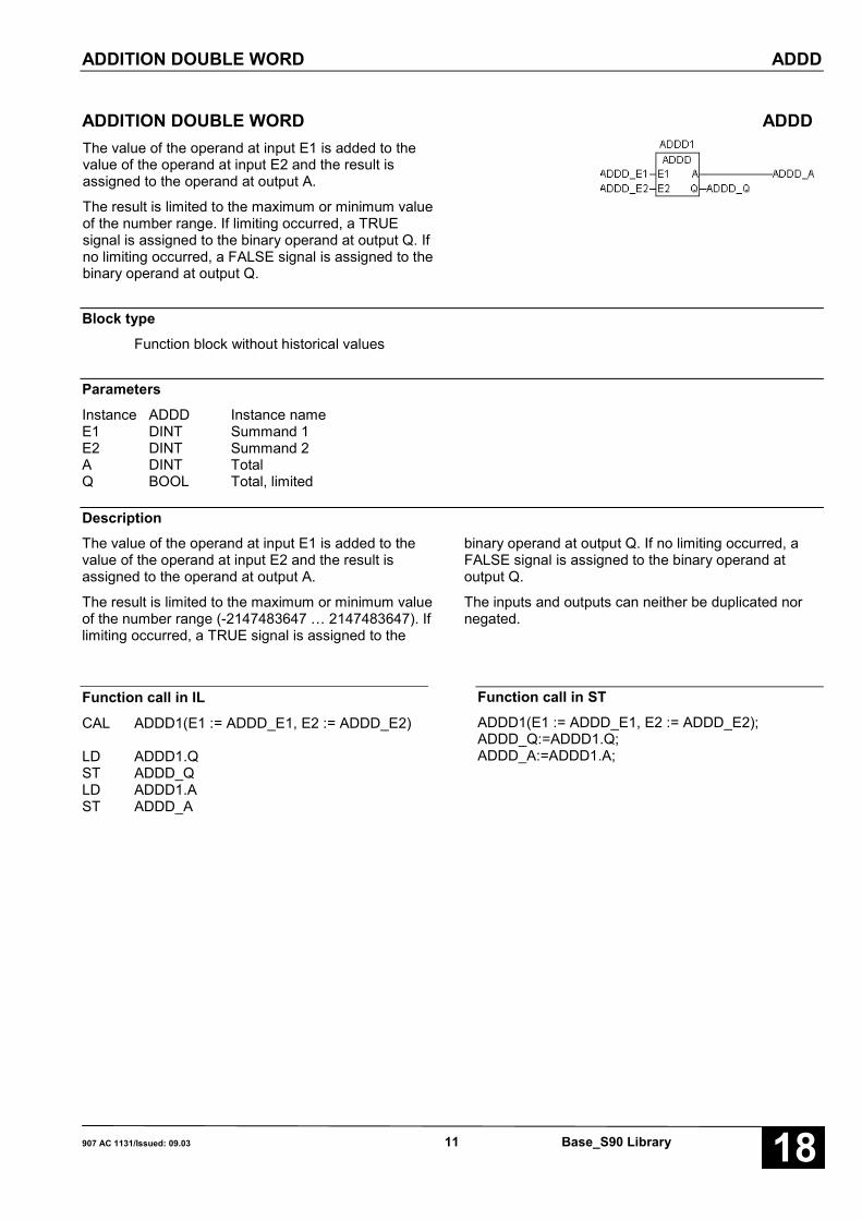
ADDITION DOUBLE WORD ADDDThe value of the operand at input E1 is added to thevalue of the operand at input E2 and the result isassigned to the operand at output A.
The result is limited to the maximum or minimum valueof the number range. If limiting occurred, a TRUEsignal is assigned to the binary operand at output Q. Ifno limiting occurred, a FALSE signal is assigned to thebinary operand at output Q.
Block typeFunction block without historical values
ParametersInstance ADDD Instance nameE1 DINT Summand 1E2 DINT Summand 2A DINT TotalQ BOOL Total, limited
DescriptionThe value of the operand at input E1 is added to thevalue of the operand at input E2 and the result isassigned to the operand at output A.
The result is limited to the maximum or minimum valueof the number range (-2147483647 … 2147483647). Iflimiting occurred, a TRUE signal is assigned to the
binary operand at output Q. If no limiting occurred, aFALSE signal is assigned to the binary operand atoutput Q.
The inputs and outputs can neither be duplicated nornegated.
Function call in IL
CAL ADDD1(E1 := ADDD_E1, E2 := ADDD_E2)
LD ADDD1.QST ADDD_QLD ADDD1.AST ADDD_A
Function call in STADDD1(E1 := ADDD_E1, E2 := ADDD_E2);ADDD_Q:=ADDD1.Q;ADDD_A:=ADDD1.A;
ADDITION WORD ADDW
Base_S90 Library 12 907 AC 1131/Stand: 09.0318
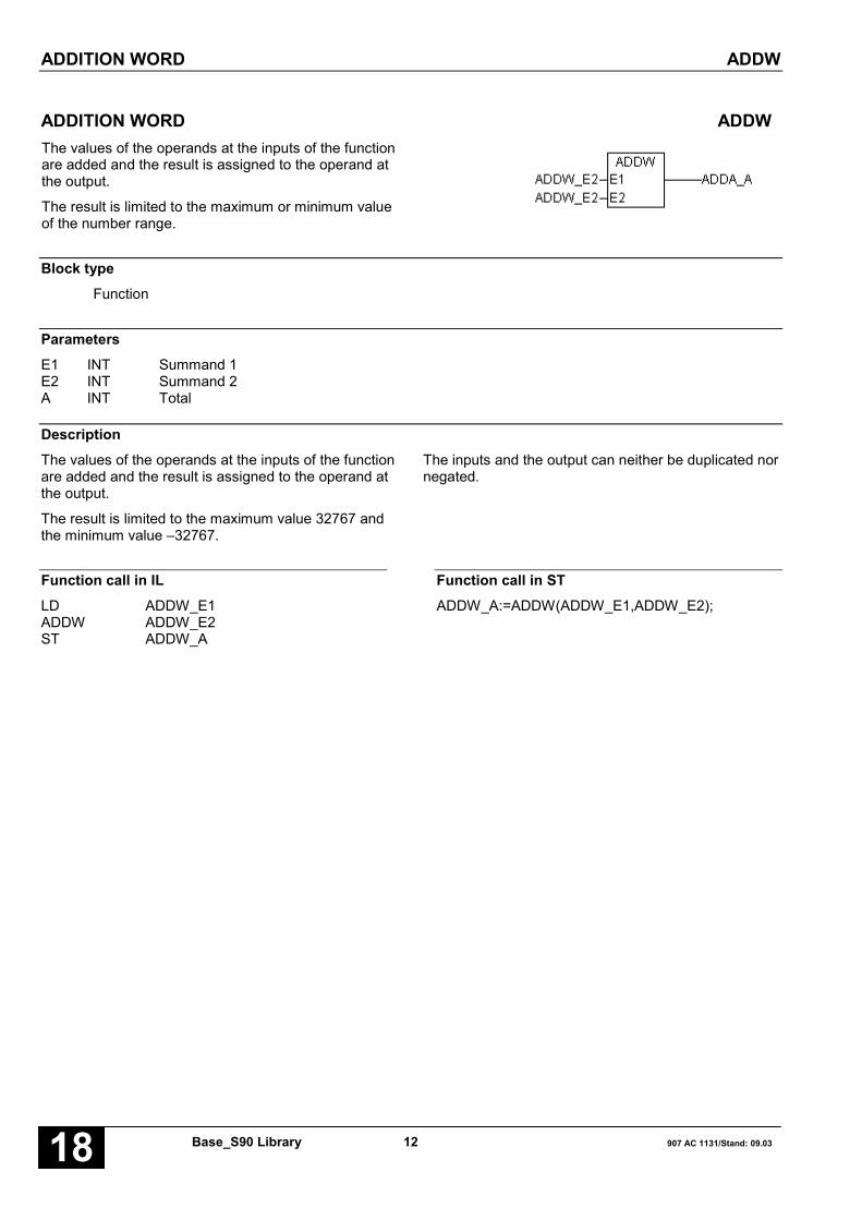
ADDITION WORD ADDWThe values of the operands at the inputs of the functionare added and the result is assigned to the operand atthe output.
The result is limited to the maximum or minimum valueof the number range.
Block typeFunction
ParametersE1 INT Summand 1E2 INT Summand 2A INT Total
DescriptionThe values of the operands at the inputs of the functionare added and the result is assigned to the operand atthe output.
The result is limited to the maximum value 32767 andthe minimum value –32767.
The inputs and the output can neither be duplicated nornegated.
Function call in ILLD ADDW_E1ADDW ADDW_E2ST ADDW_A
Function call in STADDW_A:=ADDW(ADDW_E1,ADDW_E2);

ADDRESS SELECTION ADRWA(8..16)
907 AC 1131/Issued: 09.03 13 Base_S90 Library 18
ADDRESS SELECTION ADRWA(8..16)One of the operands planned at the inputs AT0…ATn-1is selected with this function block. Of this selectedoperand, the indirect address is generated and isprovided at output ADR.
The ADRWA number indicates the maximum numberof reference values. The following address selectionblocks are available:
ADRWA8 Address selection with a maximum of 8reference values
ADRWA16 Address selection with a maximum of16 reference values
Block typeFunction block without historical values
ParametersInstance ADRWA(8..16) Instance nameE INT Input valueN INT Number of reference valuesEC0..ECn-1 INT Input codeAT0..ATn-1 INT Output tableE=EC BOOL Input value = input codeADRE DWORD 32 bit address
DescriptionOne of the operands planned at the inputs AT0 … ATn-1 is selected with this function block. Of this selectedoperand, the indirect address is generated and isprovided at output ADR.
Reading/writing operands indirectlyThe blocks AWM or USM use the 32 bit addressgenerated by the block ADRWA in order to read orwrite the operand selected with the block ADRWA.Therefore, the block ADRWA and the block AWM orUSM is needed to read or write operands indirectly. Todo this, the operands to be read or written are listed atthe inputs AT0 … ATn-1 and the read or write access itthen performed by the AWM or USM block.
Advantages of indirect addressing:
• In suitable applications, the PLC program is simplifiedsubstantially, thus reducing the planning effort.
• Access to any operands (multiplex function) isachieved with only one block (AWM or USM). In thisprocess, the ADRWA block represents a powerfultool with which the operands to be accessed can beselected in a very flexible manner.
ADDRESS SELECTION ADRWA(8..16)
Base_S90 Library 14 907 AC 1131/Stand: 09.0318
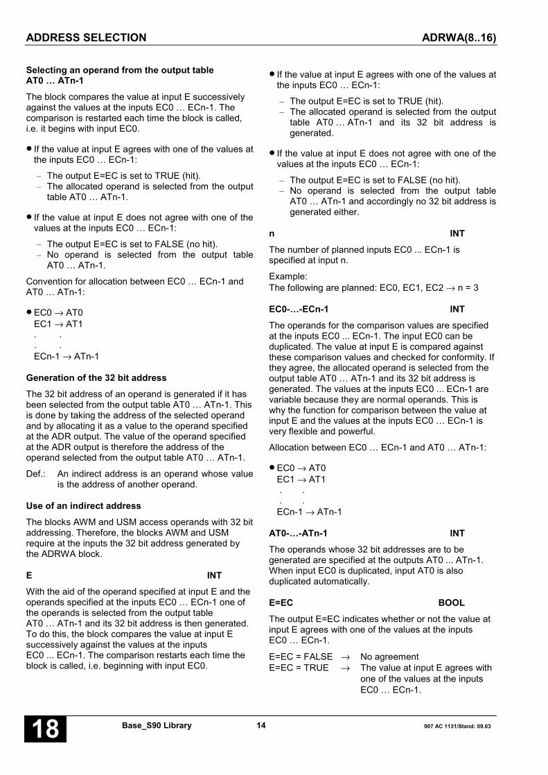
Selecting an operand from the output tableAT0 … ATn-1The block compares the value at input E successivelyagainst the values at the inputs EC0 … ECn-1. Thecomparison is restarted each time the block is called,i.e. it begins with input EC0.
• If the value at input E agrees with one of the values atthe inputs EC0 … ECn-1:
– The output E=EC is set to TRUE (hit).– The allocated operand is selected from the output
table AT0 … ATn-1.
• If the value at input E does not agree with one of thevalues at the inputs EC0 … ECn-1:
– The output E=EC is set to FALSE (no hit).– No operand is selected from the output table
AT0 … ATn-1.
Convention for allocation between EC0 … ECn-1 andAT0 … ATn-1:
• EC0 → AT0EC1 → AT1. .. .ECn-1 → ATn-1
Generation of the 32 bit addressThe 32 bit address of an operand is generated if it hasbeen selected from the output table AT0 … ATn-1. Thisis done by taking the address of the selected operandand by allocating it as a value to the operand specifiedat the ADR output. The value of the operand specifiedat the ADR output is therefore the address of theoperand selected from the output table AT0 … ATn-1.
Def.: An indirect address is an operand whose valueis the address of another operand.
Use of an indirect addressThe blocks AWM and USM access operands with 32 bitaddressing. Therefore, the blocks AWM and USMrequire at the inputs the 32 bit address generated bythe ADRWA block.
E INTWith the aid of the operand specified at input E and theoperands specified at the inputs EC0 … ECn-1 one ofthe operands is selected from the output tableAT0 … ATn-1 and its 32 bit address is then generated.To do this, the block compares the value at input Esuccessively against the values at the inputsEC0 ... ECn-1. The comparison restarts each time theblock is called, i.e. beginning with input EC0.
• If the value at input E agrees with one of the values atthe inputs EC0 … ECn-1:
– The output E=EC is set to TRUE (hit).– The allocated operand is selected from the output
table AT0 … ATn-1 and its 32 bit address isgenerated.
• If the value at input E does not agree with one of thevalues at the inputs EC0 … ECn-1:
– The output E=EC is set to FALSE (no hit).– No operand is selected from the output table
AT0 … ATn-1 and accordingly no 32 bit address isgenerated either.
n INTThe number of planned inputs EC0 ... ECn-1 isspecified at input n.
Example:The following are planned: EC0, EC1, EC2 → n = 3
EC0-…-ECn-1 INTThe operands for the comparison values are specifiedat the inputs EC0 ... ECn-1. The input EC0 can beduplicated. The value at input E is compared againstthese comparison values and checked for conformity. Ifthey agree, the allocated operand is selected from theoutput table AT0 … ATn-1 and its 32 bit address isgenerated. The values at the inputs EC0 ... ECn-1 arevariable because they are normal operands. This iswhy the function for comparison between the value atinput E and the values at the inputs EC0 … ECn-1 isvery flexible and powerful.
Allocation between EC0 … ECn-1 and AT0 … ATn-1:
• EC0 → AT0EC1 → AT1 . . . .ECn-1 → ATn-1
AT0-…-ATn-1 INTThe operands whose 32 bit addresses are to begenerated are specified at the outputs AT0 ... ATn-1.When input EC0 is duplicated, input AT0 is alsoduplicated automatically.
E=EC BOOLThe output E=EC indicates whether or not the value atinput E agrees with one of the values at the inputsEC0 … ECn-1.
E=EC = FALSE → No agreementE=EC = TRUE → The value at input E agrees with
one of the values at the inputsEC0 … ECn-1.
ADDRESS SELECTION ADRWA(8..16)
907 AC 1131/Issued: 09.03 15 Base_S90 Library 18
ADRE DWORDThe value of the operand at output ADR represents a32 bit address. This is the 32 bit address of theoperand selected from the output table AT0 … ATn-1.The 32 bit address is produced by allocating theaddress of the selected operand as a value to theoperand at output ADR.
If no agreement between input E and the inputsEC0 … ECn-1 is determined during comparison, thenno 32 bit address is generated either. Therefore, novalue is assigned to output ADR. In this case, the ADRoutput is not updated.
Function call in ILCAL ADRWA81(E := ADRWA_E, n := 3,
EC0 := EC0, EC1 := EC1, EC2 := EC2,AT0 := AT0, AT1 := AT1, AT2 := AT2)
LD ADRWA81.ADREST ADRWA_ADRELD ADRWA81.E_ECST ADRWA_E_EC
Note: The function call in IL has to be performed inone line.
Function call in STADRWA81(E := ADRWA_E, n := 3,EC0 := EC0, EC1 := EC1, EC2 := EC2,AT0 := AT0, AT1 := AT1, AT2 := AT2);ADRWA_ADRE:=ADRWA81.ADRE;ADRWA_E_EC:=ADRWA81.E_EC;

ANALOG VALUE CHANGE ANNUNCIATOR, WORD AMELD(8..127)
Base_S90 Library 16 907 AC 1131/Stand: 09.0318
ANALOG VALUE CHANGE ANNUNCIATOR, WORD AMELD(8..127)This block monitors the analog values present at inputE0 capable of duplication for a change.
The AMELD number indicates the maximum number ofinput values. The following change annunicators areavailable:
AMELD8: Analog value change annunciator witha maximum of 8 input values
AMELD16: Analog value change annunciator witha maximum of 16 input values
AMELD32: Analog value change annunciator witha maximum of 32 input values
AMELD127: Analog value change annunciator witha maximum of 127 input values
Block typeFunction block with historical values
ParametersInstance AMELD(8..32) Instance nameFREI BOOL Block enablingRESET BOOL Resetn INT Number of input valuesE0..En-1 INT Input values; input can be duplicatedNR INT Number of the input valueA INT Current input valueAEND BOOL Change detected
DescriptionThis block monitors the analog values present at theinput E0..En-1 capable of duplication for a change.
The inputs and outputs cannot be negated/inverted.The input E0 can be duplicated.
Recognition of a changeEach time the block is processed, the current inputvalues at the inputs E0 ... En-1 are successivelycompared against the historical values (input valuesfrom the previous processing of the block). If a changeis recognized at one of the inputs E0 ... En-1:
– this is indicated at the AEND output
– the number of the input where the change wasrecognized is applied at output NR
– the changed input value is applied at output A
Each time the block is processed, a change at only oneinput is recognized. If a change is recognized, theinputs following the one where the change waspreviously determined are monitored the next time theblock is processed.
Initialization of historical valuesThe first time the block is processed after PLCinitialization (FREI = TRUE) or enabling of processingafter it has been disabled (FREI changes from FALSEto TRUE), all current input values are assumed once ashistorical values and all outputs are set to the valueFALSE. These initialized historical values nowrepresent the starting basis for recognition of changes.
FREI BOOLProcessing of the block is enabled with the FREI input.
FREI = FALSE → Block is not processedFREI = TRUE → Processing of the block is
enabled
If FREI = FALSE, the outputs of the block are also nolonger updated.
RESET BOOLThe block can be reset with the RESET input.

ANALOG VALUE CHANGE ANNUNCIATOR, WORD AMELD(8..127)
907 AC 1131/Issued: 09.03 17 Base_S90 Library 18
RESET = FALSE → No resetRESET = TRUE → Reset of the block
A reset means:– Adoption of the current values at the inputs E0 ... En-1
as historical values.– All outputs are set to the value FALSE.
n INTThe number of values to be monitored at the inputsE0 ... En-1 is specified at input n.
Range for n: 1 < n < max. number (8..127)
E0…En-1 INTThe input E0 can be duplicated (E0 ... En-1). Theoperands to be monitored for a change are specified atthe inputs E0 ... En-1.
NR INT
The serial number of the input E0 ... En-1 where achange has been determined is applied at output NR. Ifno output change is determined during processing ofthe block, the number of the last changed input is stillapplied at output NR.
The following allocation applies:
Change determined at E0 → NR = 0Change determined at E1 → NR = 1Change determined at En-1 → NR = n-1
A INTIf a change is determined at one of the inputs E0 ... En-1,the changing input value is assigned to output A. If nochange is determined at the inputs E0 ... En-1 duringprocessing of the block, the value of the last changedinput is still applied at output A.
AEND BOOLThe output AEND indicates whether or not a changehas been determined at the inputs E0 ... En-1.
AEND = FALSE → No change determinedAEND = TRUE → Change determined
Function call in ILCAL AMELD81(FREI := AM_FREI,
RESET := AM_RESET, n := 3, E0 := AM_E0,E1 := AM_E1, E2 := AM_E2)
LD AMELD81.AST AM_ALD AMELD81.AENDST AM_AENDLD AMELD81.NRST AM_NR
Note: In IL, the function call has to be performed inone line.
Function call in STAMELD81(FREI := AM_FREI,RESET := AM_RESET, n := 3, E0 := AM_E0,E1 := AM_E1, E2 := AM_E2);AM_A:=AMELD81.A;AM_AEND:=AMELD81.AEND;AM_NR:=AMELD81.NR;

ANALOG VALUE CHANGE ANNUNCIATOR, DOUBLE WORD AMELDD(8..63)
Base_S90 Library 18 907 AC 1131/Stand: 09.0318
ANALOG VALUE CHANGE ANNUNCIATOR, DOUBLE WORD AMELDD(8..63)This block monitors the analog values present at inputE0 capable of duplication for a change.
The AMELD number indicates the maximum number ofinput values. The following change annunciators areavailable:
AMELDD8 Analog value change annunciator witha maximum of 8 input values
AMELDD16 Analog value change annunciator witha maximum of 16 input values
AMELDD32 Analog value change annunciator witha maximum of 32 input values
AMELDD63 Analog value change annunciator witha maximum of 63 input values
Block typeFunction block with historical values
ParametersInstance AMELD(8..32) Instance nameFREI BOOL Block enablingRESET BOOL ResetN INT Number of input valuesE0..En-1 DINT Input values; input can be duplicatedNR INT Number of the input valueA DINT Current input valueAEND BOOL Change detected
DescriptionThis block monitors the analog values present at inputE0..En-1 capable of duplication for a change.
The inputs and outputs cannot be negated/inverted.The input E0 can be duplicated.
Recognition of a changeEach time the block is processed, the current inputvalues at the inputs E0 ... En-1 are successivelycompared against the historical values (input valuesfrom the previous processing of the block). If a changeis recognized at one of the inputs E0 ... En-1:
– this is indicated at the AEND output
– the number of the input where the change wasrecognized is applied at output NR
– the changed input value is applied at output A
Each time the block is processed, a change at only oneinput is recognized. If a change is recognized, theinputs following the one where the change waspreviously determined are monitored the next time theblock is processed.
Initialization of historical valuesThe first time the block is processed after PLCinitialization (FREI = TRUE) or enabling of processingafter it has been disabled (FREI changes from FALSEto TRUE), all current input values are assumed once ashistorical values and all outputs are set to the valueFALSE. These initialized historical values nowrepresent the starting basis for recognition of changes.
FREI BOOLProcessing of the block is enabled with the FREI input.
FREI = FALSE → Block is not processedFREI = TRUE → Processing of the block is
enabled
If FREI = FALSE, the outputs of the block are also nolonger updated.

ANALOG VALUE CHANGE ANNUNCIATOR, DOUBLE WORD AMELDD(8..63)
907 AC 1131/Issued: 09.03 19 Base_S90 Library 18
RESET BOOLThe block can be reset with the RESET input.
RESET = FALSE → No resetRESET = TRUE → Reset of the block
A reset means:– Adoption of the current values at the inputs E0 ... En-1
as historical values.– All outputs are set to the value FALSE.
n INTThe number of values to be monitored at the inputsE0 ... En-1 is specified at input n.
Range for n: 1 < n < max. number (8..63)
E0…En-1 DINTThe input E0 can be duplicated (E0 ... En-1). Theoperands to be monitored for a change are specified atthe inputs E0 ... En-1.
NR INTThe serial number of the input E0 ... En-1 where achange has been determined is applied at output NR. Ifno output change is determined during the processingof the block, the number of the last changed input is stillapplied at output NR.
The following allocation applies:
Change determined at E0 → NR = 0Change determined at E1 → NR = 1Change determined at En-1 → NR = n-1
A DOUBLE WORDIf a change is determined at one of the inputs E0 ... En-1,the changed input value is assigned to output A. If nochange is determined at the inputs E0 ... En-1 duringthe processing of the block, the value of the lastchanged input is still applied at output A.
AEND BOOLThe output AEND indicates whether or not a changehas been determined at the inputs E0 ... En-1.
AEND = FALSE → No change determinedAEND = TRUE → Change determined
Function call in ILCAL AMELDD81(FREI := AMD_FREI,
RESET := AMD_RESET, n := 3,E0 := AMD_E0, E1 := AMD_E1,E2 := AMD_E2)
LD AMELDD81.AST AMD_ALD AMELDD81.AENDST AMD_AENDLD AMELDD81.NRST AMD_NR
Note: In IL, the function call has to be performed inone line.
Function call in STAMELDD81(FREI := AMD_FREI,RESET := AMD_RESET, n := 3, E0 := AMD_E0,E1 := AMD_E1, E2 := AMD_E2);AMD_A:=AMELDD81.A;AMD_AEND:=AMELDD81.AEND;AMD_NR:=AMELDD81.NR;

OFF DELAY ASV
Base_S90 Library 20 907 AC 1131/Stand: 09.0318
OFF DELAY ASVThe TRUE/FALSE edge of input E is delayed by thetime T and is output as a TRUE/FALSE edge atoutput A.
If input E returns to the TRUE level before the time T isexpired, output A remains in the TRUE level.
Block typeFunction block with historical values
ParametersInstance ASV Instance nameE BOOL Input signalT TIMER Delay timeA BOOL Delayed signal
DescriptionThe TRUE/FALSE edge of input E (input 0HT in thefigure) is delayed by the time T and is output as aTRUE/FALSE edge at output A (output Q in the figure).
If input E returns to the TRUE level before the time T isexpired, output A remains in the TRUE level.
Maximum time offset at the output: < 1 cycle time
Reasonable range for T: > 1 cycle time
The inputs and the output can neither be duplicated norinverted.
General behavior
Started timers are processed by the PLC’s operatingsystem and are therefore completely independent ofPLC program processing. The operating system doesnot issue a corresponding message to thecorresponding timer block in the PLC program until thetimer has elapsed.
Function call in ILCAL ASV1(E := ASV_E, T := T#200ms)
LD ASV1.AST ASV_A
Function call in STASV1(E := ASV_E, T := T#200ms);ASV_A:=ASV1.A;

SELECTION MULTIPLEXER AWM
907 AC 1131/Issued: 09.03 21 Base_S90 Library 18
SELECTION MULTIPLEXER AWMThis block reads the value of an operand, using themethod of indirect addressing. The value read isassigned to output A.
Note:The AWM block can only be used meaningfully inconjunction with the ADRWA block.
Block typeFunction
ParametersADRESSE DWORD Indirect address of the operand to be readA INT Value of the operand read
DescriptionThis block reads the value of an operand, using themethod of indirect addressing. The value read isassigned to output A.
Note:The AWM block can only be used meaningfully inconjunction with the ADRWA block.
The value of the operand at input ADRESSE isinterpreted as an address of the operand to be read(indirect addressing).
This indirect address is generated by the ADRWAblock.
The input and output can neither be duplicated nornegated.
Note:An explanation of the indirect addressing method andthe possibilities of using the AWM block are describedin the section dealing with the ADRWA block.
Function call in ILLD AWM_ADRAWMST AWM_A
Function call in STAWM_A:=AWM( AWM_ADR);

BCD TO DUAL CONVERSION, WORD BCDDUAL
Base_S90 Library 22 907 AC 1131/Stand: 09.0318
BCD TO DUAL CONVERSION, WORD BCDDUALThe positive BCD coded number at input E isconverted to a binary number and is assigned to theoperand at output A.
Block typeFunction
ParametersE INT BCD coded numberA INT Binary number
DescriptionThe positive BCD coded number at input E is convertedto a binary number and is assigned to the operand atoutput A.
The input and the output can neither be duplicated nornegated.
Definition:The significance of the digits in a BCD coded numberand a hexadecimal number is defined as follows:
BCD NUMBER HEXDEC NUMBER
15 11 7 3 0 BIT 15 11 7 3 0
Z4 Z3 Z2 Z1 Z4 Z3 Z2 Z1
Numerical value:Z1 * 1Z2 * 10Z3 * 100Z4 * 1000
Numerical value:Z1 * 1Z2 * 16Z3 * 256Z4 * 4096
0 < Zi < 9 0 < Zi < F
Remark:
At the BCD input, the block additionally accepts digitsto which the following applies:
0 < Zi < F

BCD TO DUAL CONVERSION, WORD BCDDUAL
907 AC 1131/Issued: 09.03 23 Base_S90 Library 18
Example 1
BCD NUMBER HEXDEC NUMBER
15 11 7 3 0 BIT 15 11 7 3 0
1 2 3 4 ���� 0 4 D 2
Z1 = 4 * 1 = 4
Z2 = 3 * 10 = 30
Z3 = 2 * 100 = 200
Z4 = 1 * 1000 = 1000
1234
Z1 = 2 * 1 = 2
Z2 = 13 * 16 = 208
Z3 = 4 * 256 = 1024
Z4 = 0 * 4096 = 0
1234
Example 2
BCD NUMBER HEXDEC NUMBER
15 11 7 3 0 BIT 15 11 7 3 0
A 2 F 4 ���� 2 8 7 2
Z1 = 4 * 1 = 4
Z2 = 15 * 10 = 150
Z3 = 2 * 100 = 200
Z4 = 10 * 1000 = 10000
10354
Z1 = 2 * 1 = 2
Z2 = 7 * 16 = 112
Z3 = 8 * 256 = 2048
Z4 = 2 * 4096 = 8192
10354
Representation of a negative BCD numberA negative BCD number can be represented in the PLCby separate representation of the value and the sign. Indoing so, the value of the BCD number is stored in aword variable and the information about the sign isstored in a binary variable.
Function call in ILLD BCD_EBCDDUALST BCD_A
Function call in STBCD_A:=BCDDUAL(BCD_E);
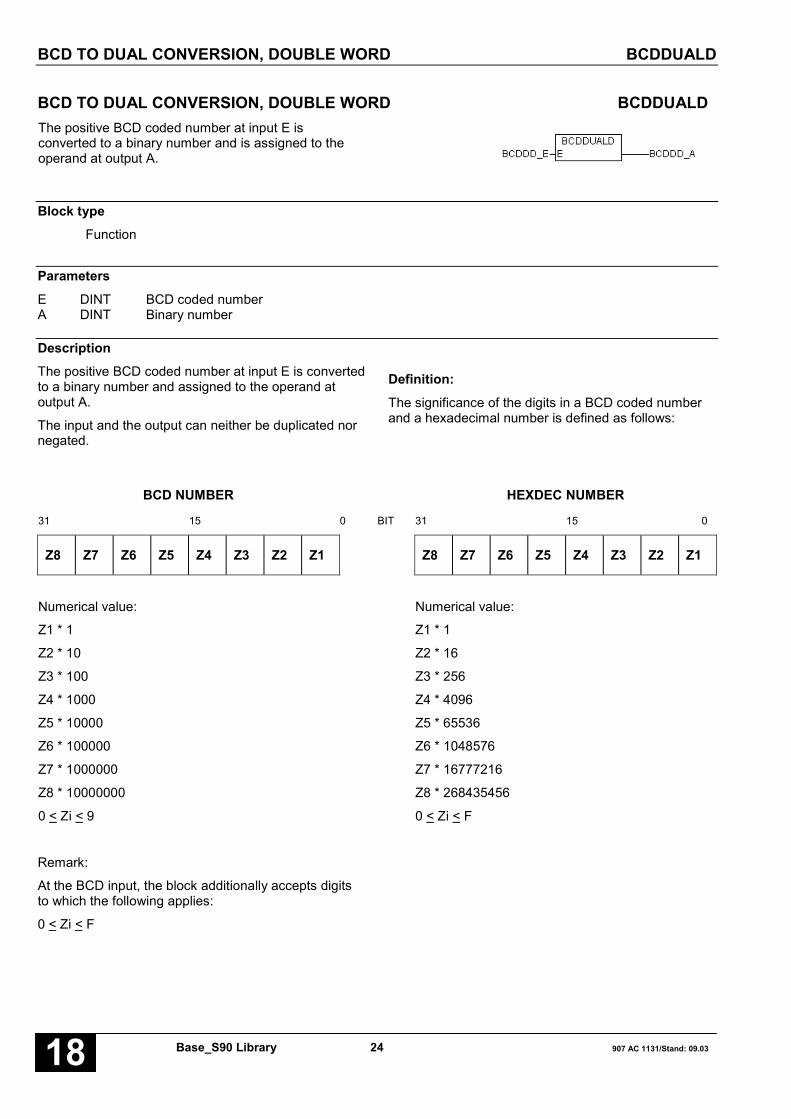
BCD TO DUAL CONVERSION, DOUBLE WORD BCDDUALD
Base_S90 Library 24 907 AC 1131/Stand: 09.0318
BCD TO DUAL CONVERSION, DOUBLE WORD BCDDUALDThe positive BCD coded number at input E isconverted to a binary number and is assigned to theoperand at output A.
Block typeFunction
ParametersE DINT BCD coded numberA DINT Binary number
DescriptionThe positive BCD coded number at input E is convertedto a binary number and assigned to the operand atoutput A.
The input and the output can neither be duplicated nornegated.
Definition:The significance of the digits in a BCD coded numberand a hexadecimal number is defined as follows:
BCD NUMBER HEXDEC NUMBER
31 15 0 BIT 31 15 0
Z8 Z7 Z6 Z5 Z4 Z3 Z2 Z1 Z8 Z7 Z6 Z5 Z4 Z3 Z2 Z1
Numerical value:
Z1 * 1
Z2 * 10
Z3 * 100
Z4 * 1000
Z5 * 10000
Z6 * 100000
Z7 * 1000000
Z8 * 10000000
Numerical value:
Z1 * 1
Z2 * 16
Z3 * 256
Z4 * 4096
Z5 * 65536
Z6 * 1048576
Z7 * 16777216
Z8 * 268435456
0 < Zi < 9 0 < Zi < F
Remark:
At the BCD input, the block additionally accepts digitsto which the following applies:
0 < Zi < F

BCD TO DUAL CONVERSION, DOUBLE WORD BCDDUALD
907 AC 1131/Issued: 09.03 25 Base_S90 Library 18
Example 1
BCD NUMBER HEXDEC NUMBER
31 15 0 BIT 31 15 0
1 2 3 4 5 6 7 8 ���� 0 0 B C 6 1 4 E
Z1 = 8 * 1 = 8
Z2 = 7 * 10 = 70
Z3 = 6 * 100 = 600
Z4 = 5 * 1000 = 5000
Z5 = 4 * 10000 = 40000
Z6 = 3 * 100000 = 300000
Z7 = 2 * 1000000 = 2000000
Z8 = 1 * 10000000 = 10000000
12345678
Z1 = 14 * 1 = 14
Z2 = 4 * 16 = 64
Z3 = 1 * 256 = 256
Z4 = 6 * 4096 = 24576
Z5 = 12 * 65536 = 786432
Z6 = 11 * 1048576 = 11534336
Z7 = 0 * 16777216 = 0
Z8 = 0 * 268435456 = 0
12345678
Example 2
BCD NUMBER HEXDEC NUMBER
31 15 0 BIT 31 15 0
1 B 3 4 A 2 F 4 ���� 0 1 2 3 C 7 D 2
Z1 = 4 * 1 = 4
Z2 = 15 * 10 = 150
Z3 = 2 * 100 = 200
Z4 = 10 * 1000 = 10000
Z5 = 4 * 10000 = 40000
Z6 = 3 * 100000 = 300000
Z7 = 11 * 1000000 = 11000000
Z8 = 1 * 10000000 = 10000000
21350354
Z1 = 2 * 1 = 2
Z2 = 13 * 16 = 208
Z3 = 7 * 256 = 1792
Z4 = 12 * 4096 = 49152
Z5 = 5 * 65536 = 327680
Z6 = 4 * 1048576 = 4194304
Z7 = 1 * 16777216 = 16777216
Z8 = 0 * 268435456 = 0
21350354
Representation of a negative BCD numberA negative BCD number can be represented in the PLCby separate representation of the value and the sign. Indoing so, the value of the BCD number is stored in adouble word variable and the information about the signis stored in a binary variable.
Function call in ILLD BCDD_EBCDDUALDST BCDD_A
Function call in STBCDD_A:=BCDDUALD(BCDD_E);
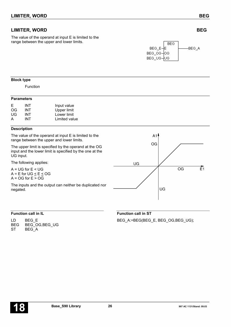
LIMITER, WORD BEG
Base_S90 Library 26 907 AC 1131/Stand: 09.0318
LIMITER, WORD BEGThe value of the operand at input E is limited to therange between the upper and lower limits.
Block typeFunction
ParametersE INT Input valueOG INT Upper limitUG INT Lower limitA INT Limited value
DescriptionThe value of the operand at input E is limited to therange between the upper and lower limits.
The upper limit is specified by the operand at the OGinput and the lower limit is specified by the one at theUG input.
The following applies:
A = UG for E < UGA = E for UG < E < OGA = OG for E > OG
The inputs and the output can neither be duplicated nornegated.
Function call in ILLD BEG_EBEG BEG_OG,BEG_UGST BEG_A
Function call in STBEG_A:=BEG(BEG_E, BEG_OG,BEG_UG);
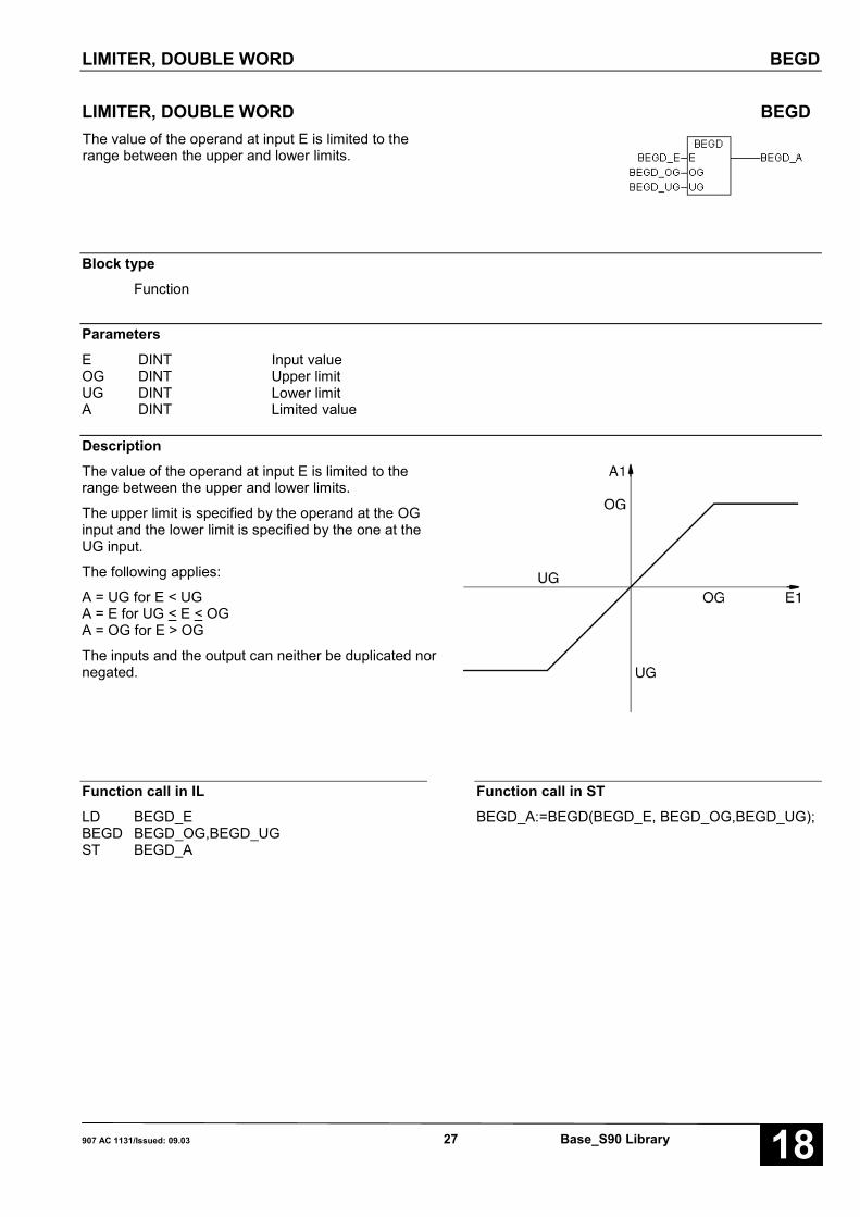
LIMITER, DOUBLE WORD BEGD
907 AC 1131/Issued: 09.03 27 Base_S90 Library 18
LIMITER, DOUBLE WORD BEGDThe value of the operand at input E is limited to therange between the upper and lower limits.
Block typeFunction
ParametersE DINT Input valueOG DINT Upper limitUG DINT Lower limitA DINT Limited value
DescriptionThe value of the operand at input E is limited to therange between the upper and lower limits.
The upper limit is specified by the operand at the OGinput and the lower limit is specified by the one at theUG input.
The following applies:
A = UG for E < UGA = E for UG < E < OGA = OG for E > OG
The inputs and the output can neither be duplicated nornegated.
Function call in ILLD BEGD_EBEGD BEGD_OG,BEGD_UGST BEGD_A
Function call in STBEGD_A:=BEGD(BEGD_E, BEGD_OG,BEGD_UG);

BIT SEARCHER BITSU
Base_S90 Library 28 907 AC 1131/Stand: 09.0318
BIT SEARCHER BITSUThis block searches through a bit field for a set bit. Thebit field consists of successive word operands. If a setbit is found, this is indicated at the block’s outputs.
Block typeFunction block with historical values
ParametersInstance BITSU Instance nameRESET BOOL Reset of the block and new searchR_V BOOL Search direction, down/upANZ INT Field length, number of word operandsANF INT Field start, 1st word operandBIT INT Number of set bits to be skippedEND BOOL Field end reachedNR INT Number of the word operand containing the set bitPOS INT Bit position within the word operand
DescriptionThis block searches through a bit field for a set bit. Thebit field consists of successive word operands. If a setbit is found, this is indicated at the block’s outputs.
The inputs and outputs can neither be duplicated nornegated/inverted.
The bit field consists of successive word operands. Thefirst word operand in the bit field is specified at inputANF.
After the start of the PLC program (1st program cycle),the block sets all outputs to the value 0 or FALSE andimmediately begins searching for set bits. Therefore,the search is already active in the first program cycle.
If the block finds a set bit, its position is indicated at theblock’s outputs and the search is ended. The next timethe block is called in the next program cycle, itcontinues the search, doing so at the bit positiondirectly following the bit found last. If the end of the bitfield is reached during the search, this is indicated anda new search can be started again by applying a resetsignal. The new search again begins at the start of thebit field.
RESET BOOLThe input RESET is used to reset the block and start anew search from the beginning of the bit field.
RESET = FALSE → No resetRESET = TRUE → Reset is triggered
A TRUE signal at input RESET resets all of the block’soutputs to the value 0 or FALSE and results inimmediate starting of a new search from the beginningof the bit field. Therefore, the new search begins in thesame processing cycle in which the block’s outputs arereset.
The search within the reset cycle ends either at the firstset bit or, if no bit is set, at the end of the field. The nexttime the block is called, the reset input must be set to 0or FALSE so that the block will be able to continuesearching through the bit field for set bits. The resetinput is dominant with respect to the other inputs.
R_V BOOLThe searching direction is specified at input R_V.
R_V = FALSE → Search upR_V = TRUE → Search down
R_V = FALSE means: The start of the bit field withinthe meaning of the search is identical with the physicalstart of the bit field.
R_V = TRUE means: The start of the bit field within themeaning of the search is identical with the physical endof the bit field.
ANZ INTThe number of word operands of which the bit fieldconsists is specified at input ANZ.

BIT SEARCHER BITSU
907 AC 1131/Issued: 09.03 29 Base_S90 Library 18
ANF INTThe word operand with which the bit field physicallybegins is specified at input ANF. The entire bit fieldconsists of the operand at input ANF and thesubsequent operands corresponding to the operandnumbering. The total number of word operands isspecified at input ANZ.
BIT INTThe way in which the block is to indicate the bits set inthe bit field is specified at input BIT.
BIT = 1 → Each set bit in the bit field is indicated atthe outputs NR and POS.
BIT = 2 → The first set bit in the bit field is indicated.Of the other set bits in the bit field, onlyevery second set bit is now indicated.
BIT = 3 → The first set bit in the bit field is indicated.Of the other set bits in the bit field, onlyevery third set bit is now indicated.
BIT = n → The first set bit in the bit field is indicated.Of the other set bits in the bit field, onlyevery n-th set bit is now indicated.
– Special function: BIT = 0If the block finds a set bit, in the next program cyclethe search is not automatically continued at thesubsequent bit position. The search is interrupted atthis point until the bit found has assumed thesignificance 0. During interruption of the search, theposition of the bit found last continues to be indicatedat the outputs. If the bit found last assumes the value0, the search is continued at the next bit position. If afurther bit is set in the selected search direction, thisbit’s position is indicated and the search isinterrupted again.
If no more bits are set in the search direction, theposition of the bit found last is indicated. The outputEND (field end reached) is set to TRUE.
– If no bits are set after a reset, the block runs throughthe bit field up to its end and stops there. The outputEND (field end reached) is set to TRUE. The outputsNR and POS are set to 0.
– If bits are set after a reset, the block indicates thefirst set bit in the search direction and stops at thisbit.
END BOOLThe output END indicates whether or not the end of thebit field has been reached during the search.
END = FALSE → End of bit field not reachedEND = TRUE → End of bit field reached
Search up:The end of the bit field is defined by bit position 15 inthe last word operand of the physical bit field.
Search down:The end of the bit field is defined by bit position 0 in thefirst word operand of the physical bit field.
If the bit is set at the last bit position of the field and it isfound and indicated during a search, the output END isnot yet set to the value TRUE. This is not done until thenext processing cycle of the block. Therefore, theprerequisite for setting the output END is that no set bithas been found during the current search.
NR, POS INTIf the block finds a set bit in the planned bit field, itsposition is indicated at the outputs NR and POS.
Meanings:
NR: Current number of the word operand in whichthe set bit has been found.
POS: Position of the set bit within the word operand.
Current number of the word operand
NR = 0 → 1st word operand of the bit fieldNR = 1 → 2nd word operand of the bit field . . . . . .NR = -1 → nth word operand of the bit field
Position of the set bit within the word operandNumbering within a word operand is from 0 ... 15.Position 0 corresponds to the least significant bit andposition 15 to the most significant bit within the wordoperand. If the end of the field is reached during asearch without a set bit having been found, the positionof the bit found last continues to be output at theoutputs NR and POS. This is performed until a newsearch is forced from the start of the bit field by a resetat input RESET.
If no bits are set at all within the entire bit field, theoutputs assume the following values at the end of thefirst search:
END = TRUENR = 0POS = 0
This state can be terminated again by a TRUE signal atinput RESET.

BIT SEARCHER BITSU
Base_S90 Library 30 907 AC 1131/Stand: 09.0318
Function call in ILCAL BITSU1(RESET := BITS_RES,
R_V := BITS_RV, ANZ := BITS_ANZ,BIT := BITS_BIT, ANF := BITS_ANF)
LD BITSU1.NRST BITS_NRLD BITSU1.POSST BITS_POSLD BITSU1.ENDST BITS_END
Note: In IL, the function call has to be performed inone line.
Function call in STBITSU1(RESET := BITS_RES, R_V := BITS_RV,ANZ := BITS_ANZ, BIT := BITS_BIT,ANF := BITS_ANF);BITS_NR:=BITSU1.NR;BITS_POS:=BITSU1.POS;BITS_END:=BITSU1.END;

BINARY VALUE CHANGE ANNUNCIATOR BMELD(8..127)
907 AC 1131/Issued: 09.03 31 Base_S90 Library 18
BINARY VALUE CHANGE ANNUNCIATOR BMELD(8..127)This block monitors the binary values present at inputE0 capable of duplication for a change.
The BMELD number indicates the maximum number ofinput values. The following change annunciators areavailable:
BMELD8 Binary value change annunciator with amaximum of 8 input values
BMELD16 Binary value change annunciator with amaximum of 16 input values
BMELD32 Binary value change annunciator with amaximum of 32 input values
BMELD127 Binary value change annunciator with amaximum of 127 input values
Block typeFunction block with historical values
ParametersInstance BMELD(8..32) Instance nameFREI BOOL Block enablingRESET BOOL ResetN INT Number of input valuesE0 … En-1 INT Input values; input can be duplicatedNR INT Number of the input valueA INT Current input valueAEND BOOL Change detected
DescriptionThis block monitors the binary values present at theinput E0 ... En-1 capable of duplication for a change.
The inputs and outputs cannot be negated/inverted.The input E0 can be duplicated.
Recognition of a changeEach time the block is processed, the current inputvalues at the inputs E0 ... En-1 are successivelycompared against the historical values (input valuesfrom the previous processing of the block). If a changeis recognized at one of the inputs E0 ... En-1:
– this is indicated at output AEND
– the number of the input where the change wasrecognized is applied at output NR
– the changed input value is applied at output A
Each time the block is processed, a change at only oneinput is recognized. If a change is recognized, theinputs following the one where the change waspreviously determined are monitored the next time the
block is processed.
Initialization of historical valuesThe first time the block is processed after PLCinitialization (FREI = TRUE) or enabling of processingafter it has been disabled (FREI changes from FALSEto TRUE), all current input values are assumed once ashistorical values and all outputs are set to the value 0.These initialized historical values now represent thestarting basis for recognition of changes.
FREI BOOLProcessing of the block is enabled with the FREI input.
FREI = FALSE → Block is not processedFREI = TRUE → Processing of the block is enabled
If FREI = FALSE, the outputs of the block are also nolonger updated.
BINARY VALUE CHANGE ANNUNCIATOR BMELD(8..127)
Base_S90 Library 32 907 AC 1131/Stand: 09.0318
RESET BOOLThe block can be reset with the RESET input.
RESET = FALSE → No resetRESET = TRUE → Reset of the block
A reset means:
– Adoption of the current values at the inputs E0 ... En-1as historical values.
– All outputs are set to the value FALSE (0).
n INTThe number of values to be monitored at the inputsE0 ... En-1 is specified at input n.
Range for n: 1 < n < max. number (8..127)
E0…En-1 BOOLThe input E0 can be duplicated (E0 ... En-1). Theoperands to be monitored for a change are specified atthe inputs E0 ... En-1.
NR INTThe serial number of the input E0 ... En-1 where achange has been determined is applied at output NR. Ifno change is determined during processing of theblock, the number of the last changed input is stillapplied at output NR.
The following allocation applies:
Change determined at E0 → NR = 0Change determined at E1 → NR = 1Change determined at En-1 → NR = n-1
A BOOLIf a change is determined at one of the inputs E0 ... En-1,the changed input value is assigned to output A. If nochange is determined at the inputs E0 ... En-1 duringprocessing of the block, the value of the last changedinput is still applied at output A.
AEND BOOLThe output AEND indicates whether or not a changehas been determined at the inputs E0 ... En-1.
AEND = FALSE → No change determinedAEND = TRUE → Change determined
Function call in ILCAL BMELD81(FREI := BM_FREI,
RESET := BM_RES, n := 3, E0 := BM_E0,E1 := BM_E1, E2 := BM_E2)
LD BMELD81.AST BM_ALD BMELD81.AENDST BM_AENDLD BMELD81.NRST BM_NR
Note: In IL, the function call has to be performed inone line.
Function call in STBMELD81(FREI := BM_FREI, RESET := BM_RES,n := 3, E0 := BM_E0, E1 := BM_E1, E2 := BM_E2);BM_A:=BMELD81.A;BM_AEND:=BMELD81.AEND;BM_NR:=BMELD81.NR;

COMPARISON OF TWO DATA BLOCKS COMPARE
907 AC 1131/Issued: 09.03 33 Base_S90 Library 18
COMPARISON OF TWO DATA BLOCKS COMPAREThis function compares two data blocks onthe addresses QADR and ZADR with alength of exactly ANZ bytes.
Block typeFunction
ParametersANZ INT Number of bytes to be comparedQADR DWORD 32 bit address of the begin of the source areaZADR DWORD 32 bit address of the begin of the target areaReturn INT Result of comparison
DescriptionThe COMPARE function compares two data blocks onthe addresses QADR and ZADR with a length ofexactly ANZ bytes.
Since the bytes are compared as unsigned char,COMPARE supplies one of the following values:
< 0 if the block on QADR is less than the block onZADR.
= 0 if the first ANZ characters as of QADR andZADR are equal to each other.
> 0 if the block on QADR is greater than the blockon ZADR.
ANZ INTNumber of bytes to be compared.
QADR DWORD32 bit address of the begin of the source area.
ZADR DWORD32 bit address of the begin of the target area.
Note:The addresses of the areas can be determined with theADR address operator.
Function call in ILLD Var1ADRST _DWORD_0LD Var2ADRST _DWORD_1LD Comp_AnzCOMPARE _DWORD_0,_DWORD_1ST Comp_Erg
Function call in STComp_Erg := COMPARE(COMP_ANZ,
ADR(var1),ADR(var2));

COPYING MEMORY AREAS COPY
Base_S90 Library 34 907 AC 1131/Stand: 09.0318
COPYING MEMORY AREAS COPYThis block copies n words from a source memory areainto a target memory area.
Block typeFunction
ParametersFREI BOOL Block enablingANZ INT Number of word(s) to be copiedQADR DWORD 32 bit address of the start of the source areaZADR DWORD 32 bit address of the start of the target area
DescriptionThis block copies n words from a source memory areainto a target memory area.
The contents of the source memory area are notchanged.
In each case, the start of the source and target memoryareas is specified at the block’s inputs by means of the32 bit address.
The inputs and outputs can neither be duplicated nornegated/inverted.
FREI BOOLBlock enabling
FREI = FALSE → The block is not processedFREI = TRUE → The block is processed
ANZ INTNumber n of words to be copied.
Thefollowing applies: 0 ≤ n ≤ +8000Hn = 0: No copyingn = 8000H: A complete segment (64 kbytes) is
copied
QADR DWORD32 bit address of the start of the source area.
ZADR DWORD32 bit address of the start of the target area.
Note:If the COPY function block is located in the PLCprogram with the lower priority, programming can beinterrupted by the program with the higher priority. Aninterrupt can be prevented by planning the COPY blockin the PLC program with the higher priority.
Function call in ILLD MW0ADRST _DWORD_0LD MW1ADRST _DWORD_1
LD COPY_FREICOPY COPY_ANZ,_DWORD_0,_DWORD_1
Function call in ST_DWORD_0:=ADR(MW0);_DWORD_1:=ADR(MW1);COPY(COPY_FREI,COPY_ANZ,_DWORD_0,_DWORD_1);

COSINE COS1
907 AC 1131/Issued: 09.03 35 Base_S90 Library 18
COSINE COS1The block calculates the cosine value from input ANGand assigns it to output AD.
Block typeFunction block without historical values
ParametersInstance COS1 Instance nameANG INT Angle 0 ... 3600 (corresponds to 0.0°....360.0°))AD DINT Cosine of the input valueERR BOOL Error, if input value is negative or greater than 3600
DescriptionThe block calculates the cosine value from input ANGand assigns it to output AD. The result is within therange of -100,000 to +100,000. If the value at ANG isnegative or greater than 3600 (360°), output AD is setto 0 and output ERR is set to TRUE.
The maximum deviation of the result is ±0.5.
ANG INTThe cosine value from the input operand ANG iscalculated. The result is available at the output operandAD.
Input:0000 for 0 degrees0001 for 0.1 degrees0010 for 1.0 degrees…3600 for 360.0 degrees
AD DINTThe cosine value of the input ANG is available at theoutput AD.
ERR BOOLThis output ERR indicates whether the input value iswithin the correct range (0 < ANG < 3600).
Input 0 ≤ ANG ≤ 3600→ ERR = FALSE und AD = COS(ANG)
Input ANG < 0 or ANG > 3600→ ERR = TRUE and AD = 0
Examples for cosine values
x angle cos (x)
180° -100000
236° -55919
90° 0
270° 0
0° 100000
360° 100000
45° 70711

COSINE COS1
Base_S90 Library 36 907 AC 1131/Stand: 09.0318
Function call in ILCAL COS11(ANG := COS_ANG)
LD COS11.ERRST COS_ERRLD COS11.ADST COS_AD
Function call in STCOS11(ANG := COS_ANG);COS_ERR:=COS11.ERR;COS_AD:=COS11.AD;

BIT COUNTER, DOUBLE WORD COUNTBD
907 AC 1131/Issued: 09.03 37 Base_S90 Library 18
BIT COUNTER, DOUBLE WORD COUNTBDThe set bits of the operand applied to input E arecounted and output to the output Anz. At output A0 thenumber of the lowest set bit is output and at the outputA1 the number of the highest set bit is output.
Block typeFunction block without historical values
ParametersInstance COUNTBD Instance nameE DINT Input valueAnz INT Number of set bitsA0 INT Number of the lowest set bitA1 INT Number of the highest set bit
DescriptionThe set bits of the operand applied to input E arecounted and output to the output Anz. At output A0 thenumber of the lowest set bit is output and at the outputA1 the number of the highest set bit is output.
For E = 0 the following applies:
Anz = 0A0 = 0A1 = 0
The inputs and the output can neither be duplicated nornegated.
Function call in ILCAL COUNTBD1(E := COD_E)
LD COUNTBD1.A0ST COD_A0LD COUNTBD1.A1ST COD_A1LD COUNTBD1.AnzST COD_ANZ
Function call in STCOUNTBD1(E := COD_E);COD_A0:=COUNTBD1.A0;COD_A1:=COUNTBD1.A1;COD_ANZ:=COUNTBD1.Anz;

BIT COUNTER, WORD COUNTBW
Base_S90 Library 38 907 AC 1131/Stand: 09.0318
BIT COUNTER, WORD COUNTBWThe set bits of the operand applied to input E arecounted and output to the output Anz. At output A0 thenumber of the lowest set bit is output and at the outputA1 the number of the highest set bit is output.
Block type
Function block without historical values
Parameters
Instance COUNTBW Instance nameE INT Input valueAnz INT Number of set bitsA0 INT Number of the lowest set bitA1 INT Number of the highest set bit
DescriptionThe set bits of the operand applied to input E arecounted and output to the output Anz. At output A0 thenumber of the lowest set bit is output and at the outputA1 the number of the highest set bit is output.
For E = 0 the following applies:
Anz = 0A0 = 0A1 = 0
The inputs and the output can neither be duplicated nornegated.
Function call in ILCAL COUNTBW1(E := COW_E)
LD COUNTBW1.A0ST COW_A0LD COUNTBW1.A1ST COW_A1LD COUNTBW1.AnzST COW_ANZ
Function call in STCOUNTBW1(E := COW_E);COW_A0:=COUNTBW1.A0;COW_A1:=COUNTBW1.A1;COW_ANZ:=COUNTBW1.Anz;
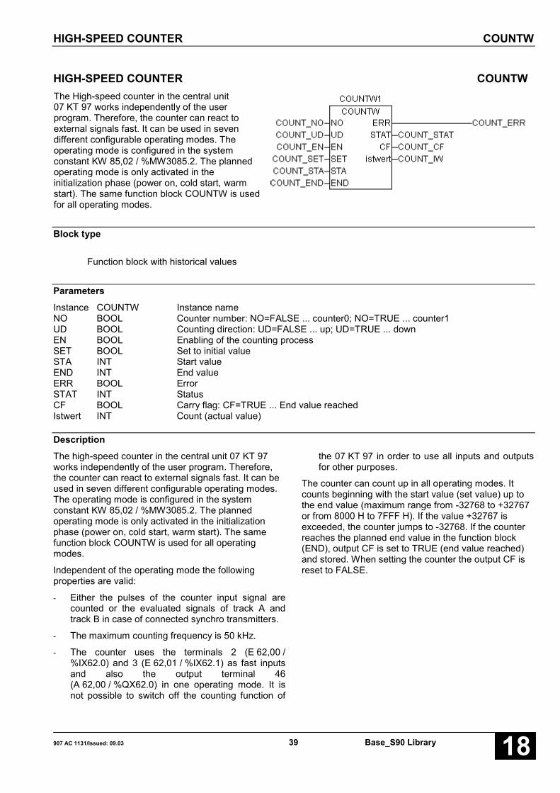
HIGH-SPEED COUNTER COUNTW
907 AC 1131/Issued: 09.03 39 Base_S90 Library 18
HIGH-SPEED COUNTER COUNTWThe High-speed counter in the central unit07 KT 97 works independently of the userprogram. Therefore, the counter can react toexternal signals fast. It can be used in sevendifferent configurable operating modes. Theoperating mode is configured in the systemconstant KW 85,02 / %MW3085.2. The plannedoperating mode is only activated in theinitialization phase (power on, cold start, warmstart). The same function block COUNTW is usedfor all operating modes.
Block type
Function block with historical values
ParametersInstance COUNTW Instance nameNO BOOL Counter number: NO=FALSE ... counter0; NO=TRUE ... counter1UD BOOL Counting direction: UD=FALSE ... up; UD=TRUE ... downEN BOOL Enabling of the counting processSET BOOL Set to initial valueSTA INT Start valueEND INT End valueERR BOOL ErrorSTAT INT StatusCF BOOL Carry flag: CF=TRUE ... End value reachedIstwert INT Count (actual value)
DescriptionThe high-speed counter in the central unit 07 KT 97works independently of the user program. Therefore,the counter can react to external signals fast. It can beused in seven different configurable operating modes.The operating mode is configured in the systemconstant KW 85,02 / %MW3085.2. The plannedoperating mode is only activated in the initializationphase (power on, cold start, warm start). The samefunction block COUNTW is used for all operatingmodes.
Independent of the operating mode the followingproperties are valid:
- Either the pulses of the counter input signal arecounted or the evaluated signals of track A andtrack B in case of connected synchro transmitters.
- The maximum counting frequency is 50 kHz.
- The counter uses the terminals 2 (E 62,00 /%IX62.0) and 3 (E 62,01 / %IX62.1) as fast inputsand also the output terminal 46(A 62,00 / %QX62.0) in one operating mode. It isnot possible to switch off the counting function of
the 07 KT 97 in order to use all inputs and outputsfor other purposes.
The counter can count up in all operating modes. Itcounts beginning with the start value (set value) up tothe end value (maximum range from -32768 to +32767or from 8000 H to 7FFF H). If the value +32767 isexceeded, the counter jumps to -32768. If the counterreaches the planned end value in the function block(END), output CF is set to TRUE (end value reached)and stored. When setting the counter the output CF isreset to FALSE.
HIGH-SPEED COUNTER COUNTW
Base_S90 Library 40 907 AC 1131/Stand: 09.0318
NO INTIn particular operating modes 2 counters can beprocessed independently of each other. In this case thefunction block is planned twice. Then the value 0 (forcounter 0) has to be applied to the first function blockand the value 1 (for counter 1) to the second functionblock. Normally NO is planned with the value 0.
UD BOOL
In some operating modes the counter can also countdown. If this is required, the input U/D (Up/Down) of thefunction block has to be configured with the valueTRUE. In this case the counter counts beginning withthe start value (set value) up to the end value(maximum range from -32768 to +32767 or from 8000Hto 7FFFH). If the value -32768 is exceeded the counterjumps to +32767.
EN BOOLThe processing of the counting signals must beenabled. Depending on the operating mode this isperformed using a terminal or the input EN (Enable) ofthe function block (EN is set to TRUE).
SET BOOLThe counter can be set to a start value. This start valuemust be applied to the input STA (start value) of thefunction block. With a set signal (depending on theoperating mode either using a terminal or the input SETof the function block) the value of the word variable istransferred to the counter.
Note: If enabling is active and the set signal is availableduring several processing cycles, the processingprocessor always sets the counter at the program end.During the remaining time of the processing cycle thecounter counts pulses.
STA INTThe counter can be set to a start value. This start valuemust be applied to the input STA (start value) of thefunction block. With a set signal (depending on theoperating mode either using a terminal or the input SETof the function block) the value of the word variable istransferred to the counter.
Note: If enabling is active and the set signal is availableduring several processing cycles, the processingprocessor always sets the counter at the program end.During the remaining time of the processing cycle thecounter counts pulses.
END INTIf the counter reaches the planned end value END, thebinary output CF is set to TRUE and the value isstored.
ERR BOOLThe binary output ERR (error) indicates that an errorcode exists in the output word STAT (error status).
STAT INTThe output word of the STAT output (error status) hasthe following meaning:
1...255 = selected operating mode inKW 85,02/ %MW3085.2.
256 = no operating mode selected(KW 85,02 / %MW3085.2 = 0)
257 = illegal operating mode planned inKW 85,02 / %MW3085.2
CF BOOLIf the counter reaches the planned end value END,output CF is set to TRUE and the value is stored. Whensetting the counter the output CF is reset to FALSE.
Istwert INTThe current counter value (actual value) can beretrieved at any time using the output Istwert of thefunction block.
The following section describes which operating modescan be configured, how they can be planned and howthey differ from each other. The system constantKW 85,02 / %MW3085.2 configures the counteroperating mode.
A hex value of the low byte (bit 0 to bit 7) of KW 85,02 /%MW3085.2 has the following meaning:
00 H = No counter (default setting)01 H = Mode 1, one count-up counter02 H = Mode 2, one count-up counter with release
input03 H = Mode 3, two count-up/count-down counters04 H = Mode 4, two count-up/count-down counters,
the second counter counts the pulses on thefalling edge
05 H = Mode 5, one count-up/count-down counter withdynamic set input, setting at rising edge
06 H = Mode 6, one count-up/count-down counter withdynamic set input, setting at falling edge
07 H = Mode 7, one count-up/count-down counter withdirectional discriminator
The high byte is configured with 00 H.
CAUTION: The planned operating mode is onlyactivated in the initialization phase (power on, coldstart, warm start).

HIGH-SPEED COUNTER COUNTW
907 AC 1131/Issued: 09.03 41 Base_S90 Library 18
- Operating mode 0: No counterThis operating mode must be selected if theinternal counter is not required. All digital inputsand outputs can then be used for other purposes.
- Operating mode 1: 1 count-up counterThe following terminals are reserved for the counterand cannot be used for other purposes:Terminal 2 (E 62,00): Counting inputTerminal 46 (A 62,00): Output "End value reached".Enabling of the counting input and the output "Endvalue reached" is performed via the function blockby setting EN to TRUE.
- Operating mode 2: 1 count-up counter withrelease input via terminalThe following three terminals are reserved for thecounter and cannot be used for other purposes:Terminal 2 (E 62,00): Counting inputTerminal 3 (A 62,01): Release inputTerminal 46 (A 62,00): Output "End value reached".The release input enables the counting input aswell as the output "End value reached". Thecounter is only enabled if the release input is set toTRUE, i.e. input EN = TRUE.
- Operating mode 3: 2 up-down countersIn this operating mode two counters existindependently of one another. The message "Endvalue reached" can only be inquired via thefunction blocks, not via the terminals. The followingtwo terminals are reserved for the counter andcannot be used for other purposes:Terminal 2 (E 62,00): Counting input counter 0Terminal 3 (A 62,01): Counting input counter 1The function block COUNTW is required twice.Note:Changing the counting direction (via U/D) is notplanned during running operation. If U/D isswitched over, at the same time the counter is setto the start value and after this counting iscontinued in the new counting direction.
- Operating mode 4: 2 counters (1 counting inputinverted)This operating mode corresponds completely to theoperating mode 3 with the only exception that thesecond counting input (counter 1) is inverted. Itcounts the edges from TRUE to FALSE atterminal 3 (E 62,01 / %IX62.1).
- Operating mode 5: 1 up-down counter withdynamic set input via terminalIn this operating mode one up-down counter withdynamic set input is available. Dynamic means thatsetting has only an effect on the signal edge andnot during application of the signal. The followingtwo terminals are reserved for the counter andcannot be used for other purposes:Terminal 2 (E 62,00 / %IX62.0): Counting inputTerminal 3 (E 62,01 / %IX62.1): Dynamic set inputThe dynamic set input at terminal 3 acts on theFALSE/TRUE edge. The message "End valuereached" can only be inquired via the functionblock, not via a terminal.Note:Changing the counting direction (via U/D) is notplanned during running operation. If U/D isswitched over, at the same time the counter is setto the start value and after this counting iscontinued in the new counting direction.
- Operating mode 6: 1 count-up counter withdynamic set input via terminalThis operating mode corresponds completely to theoperating mode 5 with the only exception that thedynamic set input acts on the TRUE/FALSE edge.
- Operating mode 7: Counter with directionaldiscriminatorIn this operating mode the synchro transmitters canbe connected using two counting pulses with anoffset of 90 degrees compared to each other.Depending on the position of the pulses the countercounts up or down. A pulse multiplication (x2 or x4)does not occur. For this procedure synchrotransmitters with a signal of 24 V can be used.Signals of 5 V synchro transmitters must beincreased. A zero track of the synchro transmitter isnot processed. The message "End value reached"can only be inquired via the function block, not viaa terminal. The following two terminals arereserved for the counter and cannot be used forother purposes:Terminal 2 (E62,00 / %IX62.0): Track A of thesynchro transmitterTerminal 3 (E 62,01 / %IX62.1): Track B of thesynchro transmitter

HIGH-SPEED COUNTER COUNTW
Base_S90 Library 42 907 AC 1131/Stand: 09.0318
Function call in ILCAL COUNTW1(NO := CW_NO, UD := CW_UD,
EN := CW_EN, SET := CW_SET,STA := CW_STA, END := CW_END)
LD COUNTW1.STATST CW_STATLD COUNTW1.CFST CW_CFLD COUNTW1.istwertST CW_ISTWERTLD COUNTW1.ERRST CW_ERR
Note: In IL, the function call has to be performed inone line.
Function call in STCOUNTW1(NO := CW_NO, UD := CW_UD,EN := CW_EN, SET := CW_SET,STA := CW_STA,END := CW_END);CW_STAT:=COUNTW1.STAT;CW_CF:=COUNTW1.CF;CW_ISTWERT:=COUNTW1.istwert;CW_ERR:=COUNTW1.ERR;

DIVISION DOPPELWORT DIVD
907 AC 1131/Issued: 09.03 43 Base_S90 Library 18
DIVISION DOUBLE WORD DIVDThe value of the operand at input E1 is divided by thevalue of the operand at input E2 and the result isassigned to the operand at output A. The remainder isassigned to the operand at the output REST. If aremainder is produced, the result will always berounded down. If the result lies outside of thepermissible number range, it will be limited to themaximum or minimum value of the number range. If alimiting has been performed, a TRUE signal isassigned to the binary operand at output Q and thevalue 0 is assigned to output REST. If no limitingoccurred, a FALSE signal is assigned to the binaryoperand at output Q.
Block typeFunction block without historical values
ParametersInstance DIVD Instance nameE1 DINT DividendE2 DINT DivisorA DINT Result (quotient)REST DINT RemainderQ BOOL Result limited
DescriptionThe value of the operand at input E1 is divided by thevalue of the operand at input E2 and the result isassigned to the operand at output A. The remainder isassigned to the operand at output REST. If a remainderis produced, the result will always be rounded down. Ifthe result lies outside of the permissible number range,it will be limited to the maximum or minimum value ofthe number range: -2147483647(8000 0001H) … 2147483647 (7FFF FFFFH). If alimiting has been performed, a TRUE signal is assignedto the binary operand at output Q and the value 0 isassigned to output REST. If no limiting occurred, aFALSE signal is assigned to the binary operand atoutput Q.
Division by »zero« is therefore also signalized at thebinary output Q.
The inputs and outputs can neither be duplicated nornegated.
Remainder handlingIf the division results in a remainder, this is available atthe double word output REST. The result of the divisionis always rounded down if a remainder occurs.
Example: 3 : 3 = 1 Remainder 04 : 3 = 1 Remainder 15 : 3 = 1 Remainder 26 : 3 = 2 Remainder 0
As the remainder is available at the output REST, theuser can compare this to the divisor and can round theresult at output A according to his own requirements.
Example:
Remainder > divisor/2 → round up the result at outputA.
Division by »zero«If the divisor has the value »zero«, the positive ornegative limit of the number range is assigned to outputA.
For the division by »zero« the following applies:
A = -2147483647 (8000 0001H) if dividend is negativeA = +2147483647 (7FFF FFFFH) if dividend is positive
REST = 0 Output for the remainder
Q = TRUE Output to signalize that the value atoutput A has been limited
Invalid result value
If the invalid value 8000 0000H is the result of thedivision, this will be corrected to the permissible limit8000 0001H (-2 147 483 647), the binary output Q willbe set to the value TRUE and the output REST will beset to the value 0.

DIVISION DOUBLE WORD DIVD
Base_S90 Library 44 907 AC 1131/Stand: 09.0318
Function call in ILCAL DIVD1(E1 := DIVD_E1,E2 := DIVD_E2)
LD DIVD1.RESTST DIVD_RESTLD DIVD1.QST DIVD_QLD DIVD1.AST DIVD_A
Function call in STDIVD1(E1 := DIVD_E1,E2 := DIVD_E2);DIVD_REST:=DIVD1.REST;DIVD_Q:=DIVD1.Q;DIVD_A:=DIVD1.A;

DIVISION WORD DIVW
907 AC 1131/Issued: 09.03 45 Base_S90 Library 18
DIVISION WORD DIVWThe value of the operand at input E1 is divided by thevalue of the operand at input E2 and the result isassigned to the operand at output A.
The result of the division is always an integer value.Rounding (i.e. considering the digits after the decimalpoint) does not take place.
Block typeFunction
ParametersE1 INT DividendE2 INT DivisorA INT Result (quotient)
DescriptionThe value of the operand at input E1 is divided by thevalue of the operand at input E2 and the result isassigned to the operand at output A.
The result of the division is always an integer value.Rounding (i.e. considering the digits after the decimalpoint) does not take place.
The result is limited to the maximum value 32767 andthe minimum value -32767.
The inputs and the output can neither be duplicated nornegated.
Division by »zero«If the divisor has the value »zero«, the positive ornegative limit of the number range is assigned to outputA.
For the division by »zero« the following applies:
A = -32767 (8001H) if the dividend is negative
A = +32767 (7FFFH) if the dividend is positive
Function call in ILLD DIVW_E1DIVW DIVW_E2ST DIVW_A
Function call in STDIVW_A:=DIVW(DIVW_E1, DIVW_E2);
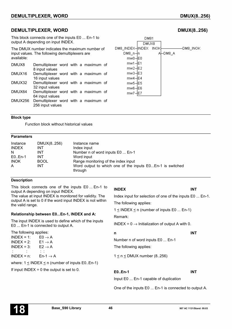
DEMULTIPLEXER, WORD DMUX(8..256)
Base_S90 Library 46 907 AC 1131/Stand: 09.0318
DEMULTIPLEXER, WORD DMUX(8..256)This block connects one of the inputs E0 ... En-1 tooutput A depending on input INDEX.
The DMUX number indicates the maximum number ofinput values. The following demultiplexers areavailable:
DMUX8 Demultiplexer word with a maximum of8 input values
DMUX16 Demultiplexer word with a maximum of16 input values
DMUX32 Demultiplexer word with a maximum of32 input values
DMUX64 Demultiplexer word with a maximum of64 input values
DMUX256 Demultiplexer word with a maximum of256 input values
Block typeFunction block without historical values
ParametersInstance DMUX(8..256) Instance nameINDEX INT Index inputN INT Number n of word inputs E0 ... En-1E0..En-1 INT Word inputINOK BOOL Range monitoring of the index inputA INT Word output to which one of the inputs E0...En-1 is switched
through
DescriptionThis block connects one of the inputs E0 ... En-1 tooutput A depending on input INDEX.The value at input INDEX is monitored for validity. Theoutput A is set to 0 if the word input INDEX is not withinthe valid range.
Relationship between E0...En-1, INDEX and A:The input INDEX is used to define which of the inputsE0 ... En-1 is connected to output A.
The following applies:INDEX = 1: E0 → AINDEX = 2: E1 → AINDEX = 3: E2 → A : : : :INDEX = n: En-1 → A
where: 1 < INDEX < n (number of inputs E0..En-1)
If input INDEX = 0 the output is set to 0.
INDEX INTIndex input for selection of one of the inputs E0 ... En-1.
The following applies:
1 < INDEX < n (number of inputs E0 ... En-1)
Remark:
INDEX = 0 → Initialization of output A with 0.
n INTNumber n of word inputs E0 ... En-1
The following applies:
1 < n < DMUX number (8..256)
E0..En-1 INTInput E0 ... En-1 capable of duplication
One of the inputs E0 ... En-1 is connected to output A.
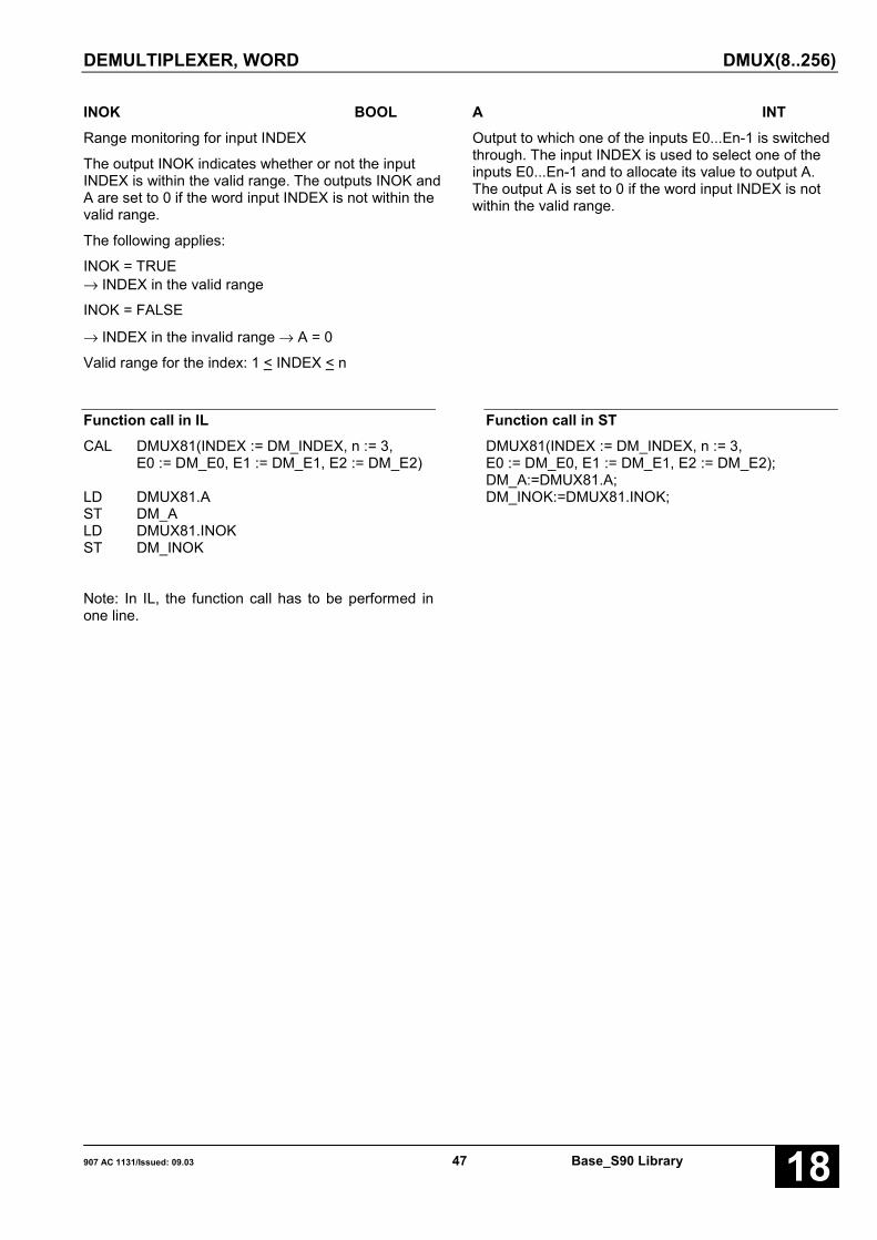
DEMULTIPLEXER, WORD DMUX(8..256)
907 AC 1131/Issued: 09.03 47 Base_S90 Library 18
INOK BOOLRange monitoring for input INDEX
The output INOK indicates whether or not the inputINDEX is within the valid range. The outputs INOK andA are set to 0 if the word input INDEX is not within thevalid range.
The following applies:
INOK = TRUE→ INDEX in the valid range
INOK = FALSE
→ INDEX in the invalid range → A = 0
Valid range for the index: 1 < INDEX < n
A INTOutput to which one of the inputs E0...En-1 is switchedthrough. The input INDEX is used to select one of theinputs E0...En-1 and to allocate its value to output A.The output A is set to 0 if the word input INDEX is notwithin the valid range.
Function call in ILCAL DMUX81(INDEX := DM_INDEX, n := 3,
E0 := DM_E0, E1 := DM_E1, E2 := DM_E2)
LD DMUX81.AST DM_ALD DMUX81.INOKST DM_INOK
Note: In IL, the function call has to be performed inone line.
Function call in STDMUX81(INDEX := DM_INDEX, n := 3,E0 := DM_E0, E1 := DM_E1, E2 := DM_E2);DM_A:=DMUX81.A;DM_INOK:=DMUX81.INOK;

DEMULTIPLEXER, DOUBLE WORD DMUXD(8..256)
Base_S90 Library 48 907 AC 1131/Stand: 09.0318
DEMULTIPLEXER, DOUBLE WORD DMUXD(8..256)This block connects one of the inputs E0 ... En-1 tooutput A depending on input INDEX.The DMUXD number indicates the maximum numberof input values. The following demultiplexers areavailable:
DMUXD8 Demultiplexer double word with amaximum of 8 input values
DMUXD16 Demultiplexer double word with amaximum of 16 input values
DMUXD32 Demultiplexer double word with amaximum of 32 input values
DMUXD64 Demultiplexer double word with amaximum of 64 input values
DMUXD256 Demultiplexer double word with amaximum of 256 input values
Block typeFunction block without historical values
ParametersInstance DMUXD(8..256) Instance nameINDEX INT Index inputN INT Number n of double word inputs E0 ... En-1E0..En-1 DINT Double word inputINOK BOOL Range monitoring of the index inputA DINT Double word output to which one of the inputs
E0...En-1 is switched through
DescriptionThis block connects one of the inputs E0 ... En-1 tooutput A depending on input INDEX. The value at inputINDEX is monitored for validity. The output A is set to 0if the double word input INDEX is not within the validrange.
Relationship between E0...En-1, INDEX and A:The input INDEX is used to define which of the inputsE0 ... En-1 is connected to output A.
The following applies:INDEX = 1: E0 → AINDEX = 2: E1 → AINDEX = 3: E2 → A : : : :INDEX = n: En-1 → A
where: 1 < INDEX < n (number of inputs E0..En-1)
If input INDEX = 0 the output is set to 0.
INDEX INTIndex input for selection of one of the inputs E0 ... En-1.
The following applies:
1 < INDEX < n (number of inputs E0 ... En-1)
Remark:INDEX = 0 → Initialization of output A with 0.
n INTNumber n of double word inputs E0 ... En-1
The following applies:
1 < n < DMUXD number (8..256)
E0..En-1 DINTInput E0 ... En-1 capable of duplication
One of the inputs E0 ... En-1 is connected to output A.

DEMULTIPLEXER, DOUBLE WORD DMUXD(8..256)
907 AC 1131/Issued: 09.03 49 Base_S90 Library 18
INOK BOOLRange monitoring for input INDEX
The output INOK indicates whether or not the inputINDEX is within the valid range. The outputs INOK andA are set to 0 if the word input INDEX is not within thevalid range.
The following applies:
INOK = TRUE→ INDEX in the valid range
INOK = FALSE
→ INDEX in the invalid range → A = 0
Valid range for the index: 1 < INDEX < n
A DINTOutput to which one of the inputs E0...En-1 is switchedthrough. The input INDEX is used to select one of theinputs E0...En-1 and to allocate its value to output A.The output A is set to 0 if the word input INDEX is notwithin the valid range.
Function call in ILCAL DMUXD81(INDEX := DMD_INDEX, n := 3,
E0 := DMD_E0, E1 := DMD_E1,E2 := DMD_E2)
LD DMUXD81.AST DMD_ALD DMUXD81.INOKST DMD_INOK
Note: In IL, the function call has to be performed inone line.
Function call in STDMUXD81(INDEX := DMD_INDEX, n := 3,E0 := DMD_E0, E1 := DMD_E1, E2 := DMD_E2);DMD_A:=DMUXD81.A;DMD_INOK:=DMUXD81.INOK;
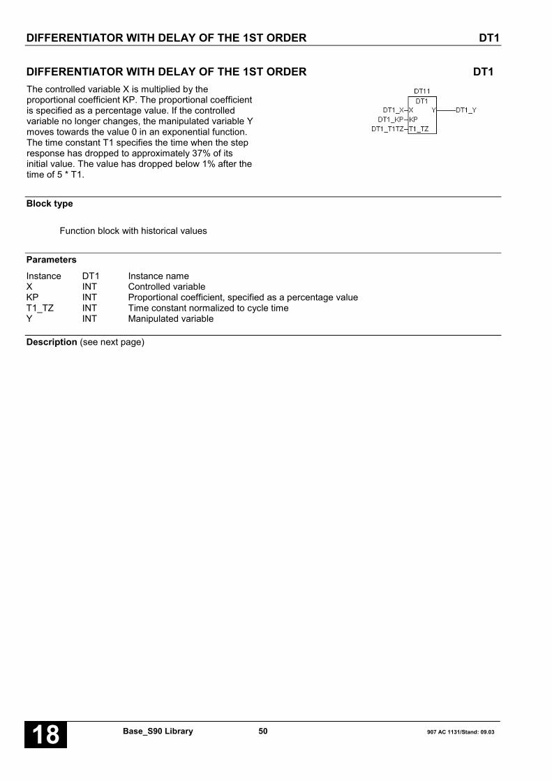
DIFFERENTIATOR WITH DELAY OF THE 1ST ORDER DT1
Base_S90 Library 50 907 AC 1131/Stand: 09.0318
DIFFERENTIATOR WITH DELAY OF THE 1ST ORDER DT1The controlled variable X is multiplied by theproportional coefficient KP. The proportional coefficientis specified as a percentage value. If the controlledvariable no longer changes, the manipulated variable Ymoves towards the value 0 in an exponential function.The time constant T1 specifies the time when the stepresponse has dropped to approximately 37% of itsinitial value. The value has dropped below 1% after thetime of 5 * T1.
Block type
Function block with historical values
ParametersInstance DT1 Instance nameX INT Controlled variableKP INT Proportional coefficient, specified as a percentage valueT1_TZ INT Time constant normalized to cycle timeY INT Manipulated variable
Description (see next page)

DIFFERENTIATOR WITH DELAY OF THE 1ST ORDER DT1
907 AC 1131/Issued: 09.03 51 Base_S90 Library 18
The controlled variable X is multiplied by theproportional coefficient KP. The proportional coefficientis specified as a percentage value. If the controlledvariable no longer changes, the manipulated variable Ymoves towards the value 0 in an exponential function.The time constant T1 specifies the time when the stepresponse has dropped to approximately 37% of itsinitial value. The value has dropped below 1% after thetime of 5 * T1.
The inputs and the output can neither be duplicated nornegated.
Transfer function:
KP * s * T1F(s) = ––––––––
s * T1 + 1
X INTThe operand for the controlled variable (input value forthe DT1 function) is specified at input X.
KP INTThe proportional coefficient is specified at input KP.This value is specified as a percentage value. Positiveor negative values are possible.
Example:
1 = 1 percent55 = 55 percent
100 = 100 percent1000 = 1000 percent-100 = -100 percent
100 percent means that input X is not influenced by theproportional coefficient.
T1_T2 INTThe time constant of the DT1 function is specified atinput T1_TZ. To do this, the time constant T1 must benormalized to the PLC cycle time T.
The following applies to T1_TZ:
10 < T1/TZ < 32767 → T1 > 10 * TZ
If a negative value is specified for T1/T, then the PLCautomatically sets T1/T to the maximum positive value+32767.
Y INTThe manipulated variable (output value of the DT1function) is applied at output Y.
Function call in ILCAL DT11(X := DT1_X, KP := DT1_KP,
T1_TZ := DT1_T1TZ)
LD DT11.YST DT1_Y
Note: In IL, the function call has to be performed inone line.
Function call in STDT11(X := DT1_X, KP := DT1_KP,T1_TZ := DT1_T1TZ);DT1_Y:=DT11.Y;

DUAL TO BCD CONVERSION, WORD DUALBCD
Base_S90 Library 52 907 AC 1131/Stand: 09.0318
DUAL TO BCD CONVERSION, WORD DUALBCDThe binary number at input E is converted to a BCDcoded number and assigned to the operand at outputA.
The binary number is represented in 16 bits and mustlie within the range 0 < E < 270FH (corresponding toBCD 9999). The BCD number is limited to 9999 if it liesoutside of this range. The BCD number is stored in a16 bit word.
Block typeFunction
ParametersE INT Binary numberA INT BCD coded number
DescriptionThe binary number at input E is converted to a BCDcoded number and assigned to the operand at outputA.
The binary number is represented in 16 bits and mustlie within the range 0 < DUAL < 270FH (correspondingto BCD 9999). The BCD number is limited to 9999 if itlies outside of this range. The BCD number is stored ina 16 bit word.
The input and the output can neither be duplicated nornegated.
Definition:The significance of the digits in a hexadecimal numberand a BCD coded number is defined as follows:
HEXDEC NUMBER BCD NUMBER
15 11 7 3 0 BIT 15 11 7 3 0
Z4 Z3 Z2 Z1 Z4 Z3 Z2 Z1
Numerical value:Z1 * 1Z2 * 16Z3 * 256Z4 * 4096
Numerical value:Z1 * 1Z2 * 10Z3 * 100Z4 * 1000
0 ≤ Zi ≤ F 0 ≤ Zi ≤ 9

DUAL TO BCD CONVERSION, WORD DUALBCD
907 AC 1131/Issued: 09.03 53 Base_S90 Library 18
Example
HEXDEC NUMBER BCD NUMBER
15 11 7 3 0 BIT 15 11 7 3 0
0 4 D 2 ���� 1 2 3 4
Z1 = 2 * 1 = 2Z2 = 13 * 16 = 208Z3 = 4 * 256 = 1024Z4 = 0 * 4096 = 0
1234
Z1 = 4 * 1 = 4Z2 = 3 * 10 = 30Z3 = 2 * 100 = 200Z4 = 1 * 1000 = 1000
1234
Conversion of a negative binary number to a BCDnumber
A negative binary number with an amount less than270FH can be converted to a BCD number, wherebythe value and the sign of the BCD number are eachstored in one flag.
Converting a binary number with an amount higherthan 270FH
Binary numbers with an amount higher than 270FH arefirst of all converted to a double word (function blockWDW). They are then converted from BINARY to BCDby means of the DUALBCDD function block.
Function call in ILLD DUAL_EDUALBCDST DUAL_A
Function call in STDUAL_A:= DUALBCD(DUAL_E);

DUAL TO BCD CONVERSION, DOUBLE WORD DUALBCDD
Base_S90 Library 54 907 AC 1131/Stand: 09.0318
DUAL TO BCD CONVERSION, DOUBLE WORD DUALBCDDThe binary number at input E is converted to a BCDcoded number and assigned to the operand at outputA.
The binary number is represented in 32 bits and mustlie within the range 0 < E < 5F5E0FFH (corresponds toBCD 99999999). The BCD number is limited to99999999 if it lies outside of this range. The BCDnumber is stored in a 32 bit word..
Block type
Function
ParametersE DINT Binary numberA DINT BCD coded number
DescriptionThe binary number at input E is converted to a BCDcoded number and assigned to the operand at outputA.
The binary number is represented in 32 bits and mustlie within the range 0 < E < 5F5E0FFH (corresponds toBCD 99999999). The BCD number is limited to99999999 if it lies outside of this range. The BCDnumber is stored in a 32 bit word.
The input and the output can neither be duplicated nornegated.
Definition:The significance of the digits in a hexadecimal numberand a BCD coded number is defined as follows:
HEXDEC NUMBER BCD NUMBER
31 15 0 BIT 31 15 0
Z8 Z7 Z6 Z5 Z4 Z3 Z2 Z1 Z8 Z7 Z6 Z5 Z4 Z3 Z2 Z1
Numerical value:Z1 * 1Z2 * 16Z3 * 256Z4 * 4096Z5 * 65536Z6 * 1048576Z7 * 16777216Z8 * 268435456
Numerical value:Z1 * 1Z2 * 10Z3 * 100Z4 * 1000Z5 * 10000Z6 * 100000Z7 * 1000000Z8 * 10000000
0 ≤ Zi ≤ F 0 ≤ Zi ≤ 9

DUAL TO BCD CONVERSION, DOUBLE WORD DUALBCDD
907 AC 1131/Issued: 09.03 55 Base_S90 Library 18
Example
BCD NUMBER HEXDEC NUMBER
31 15 0 BIT 31 15 0
0 0 B C 6 1 4 E ���� 1 2 3 4 5 6 7 8
Z1 = 14 * 1 = 14Z2 = 4 * 16 = 64Z3 = 1 * 256 = 256Z4 = 6 * 4095 = 24576Z5 = 12 * 65536 = 786432Z6 = 11 * 1048576 = 11534336Z7 = 0 * 16777216 = 0Z8 = 0 * 268435456 = 0
12345678
Z1 = 8 * 1 = 8Z2 = 7 * 10 = 70Z3 = 6 * 100 = 600Z4 = 5 * 1000 = 5000Z5 = 4 * 10000 = 40000Z6 = 3 * 100000 = 300000Z7 = 2 * 1000000 = 2000000Z8 = 1 * 10000000 = 10000000
12345678
Conversion of a negative binary number to a BCDnumber:
see function block DUALBCD
Function call in ILLD DUALD_EDUALBCDDST DUALD_A
Function call in STDUALD_A:= DUALBCDD(DUALD_E);
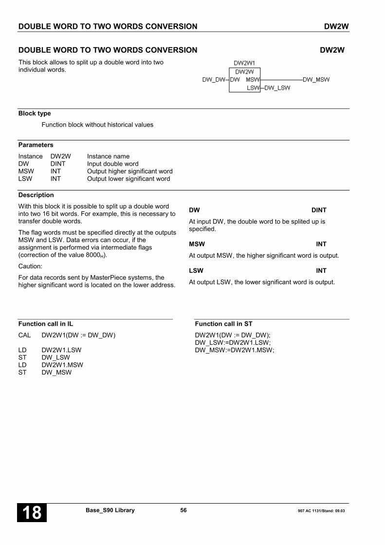
DOUBLE WORD TO TWO WORDS CONVERSION DW2W
Base_S90 Library 56 907 AC 1131/Stand: 09.0318
DOUBLE WORD TO TWO WORDS CONVERSION DW2WThis block allows to split up a double word into twoindividual words.
Block typeFunction block without historical values
ParametersInstance DW2W Instance nameDW DINT Input double wordMSW INT Output higher significant wordLSW INT Output lower significant word
DescriptionWith this block it is possible to split up a double wordinto two 16 bit words. For example, this is necessary totransfer double words.
The flag words must be specified directly at the outputsMSW and LSW. Data errors can occur, if theassignment is performed via intermediate flags(correction of the value 8000H).
Caution:
For data records sent by MasterPiece systems, thehigher significant word is located on the lower address.
DW DINTAt input DW, the double word to be splited up isspecified.
MSW INTAt output MSW, the higher significant word is output.
LSW INTAt output LSW, the lower significant word is output.
Function call in ILCAL DW2W1(DW := DW_DW)
LD DW2W1.LSWST DW_LSWLD DW2W1.MSWST DW_MSW
Function call in STDW2W1(DW := DW_DW);DW_LSW:=DW2W1.LSW;DW_MSW:=DW2W1.MSW;
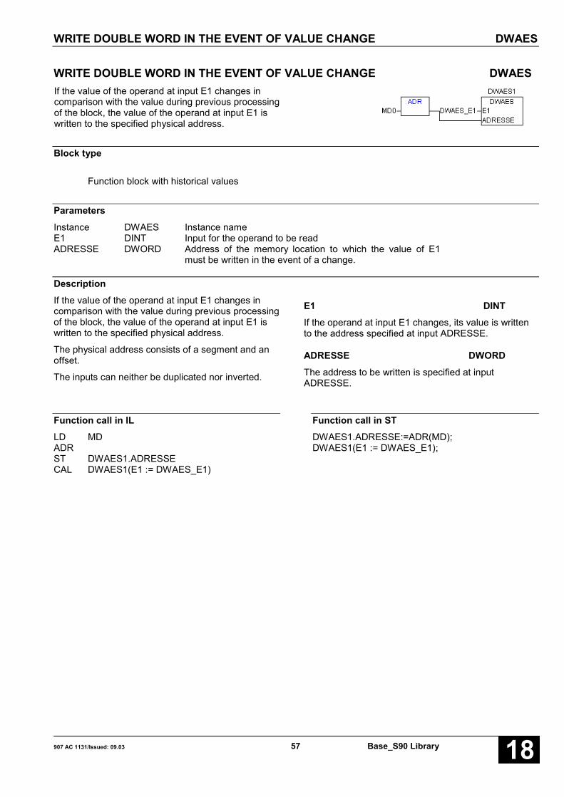
WRITE DOUBLE WORD IN THE EVENT OF VALUE CHANGE DWAES
907 AC 1131/Issued: 09.03 57 Base_S90 Library 18
WRITE DOUBLE WORD IN THE EVENT OF VALUE CHANGE DWAESIf the value of the operand at input E1 changes incomparison with the value during previous processingof the block, the value of the operand at input E1 iswritten to the specified physical address.
Block type
Function block with historical values
ParametersInstance DWAES Instance nameE1 DINT Input for the operand to be readADRESSE DWORD Address of the memory location to which the value of E1
must be written in the event of a change.
DescriptionIf the value of the operand at input E1 changes incomparison with the value during previous processingof the block, the value of the operand at input E1 iswritten to the specified physical address.
The physical address consists of a segment and anoffset.
The inputs can neither be duplicated nor inverted.
E1 DINTIf the operand at input E1 changes, its value is writtento the address specified at input ADRESSE.
ADRESSE DWORDThe address to be written is specified at inputADRESSE.
Function call in ILLD MDADRST DWAES1.ADRESSECAL DWAES1(E1 := DWAES_E1)
Function call in STDWAES1.ADRESSE:=ADR(MD);DWAES1(E1 := DWAES_E1);

READ DOUBLE WORD WITH ENABLING DWOL
Base_S90 Library 58 907 AC 1131/Stand: 09.0318
READ DOUBLE WORD WITH ENABLING DWOLIf a TRUE signal is present at input FREI, the value ofthe specified physical address is read and assigned tothe operand at output A.
Block typeFunction
ParametersFREI BOOL Enabling the blockADRESSE DWORD Address of the memory location whose double word
value is to be read.A DINT Output to which the value read is assigned.
DescriptionIf a TRUE signal is present at input FREI, the value ofthe specified physical address is read and assigned tothe operand at output A.
Reading is not performed if there is a FALSE signal atinput FREI.
The physical address is specified at input ADRESSE.
FREI BOOLProcessing of the block is enabled or disabled with theoperand at input FREI. The following applies:
FREI = FALSE → Processing disabledFREI = TRUE → Processing
ADRESSE DWORDThe 32 bit address to be read is specified at inputADRESSE.
A DINTThe value read is assigned to the operand at output A.
Function call in ILLD DWOL_FRDWOL DWOL_ADRST DWOL_A
Function call in STDWOL_A:=DWOL(DWOL_FR,DWOL_ADR);

WRITE DOUBLE WORD WITH ENABLING DWOS
907 AC 1131/Issued: 09.03 59 Base_S90 Library 18
WRITE DOUBLE WORD WITH ENABLING DWOSIf there is a TRUE signal at input FREI, the value of theoperand at input E1 is read and then written to thespecified physical address.
Block typeFunction
ParametersFREI BOOL Enabling the blockE1 DINT Input for the operand to be writtenADRESSE DWORD Address of the memory location to which the value of E1
must be written.
DescriptionIf there is a TRUE signal at input FREI, the value of theoperand at input E1 is read and then written to thespecified physical address.
Writing is not performed if there is a FALSE signal atinput FREI.
The physical address is specified at input ADRESSE.
The inputs can neither be duplicated nor inverted.
FREI BOOLProcessing of the block is enabled or disabled with theoperand at input FREI. The following applies:
FREI = FALSE → Processing disabledFREI = TRUE → Processing enabled
E1 DINTThe operand at input E1 is read and its value is writtento the address defined by the input ADR.
ADRESSE DWORDThe 32 bit address to be read is specified at inputADRESSE.
Function call in ILLD DWOS_FREIDWOS DWOS_E1,DWOS_ADR
Function call in STDWOS(DWOS_FR,DWOS_E1,DWOS_ADR);
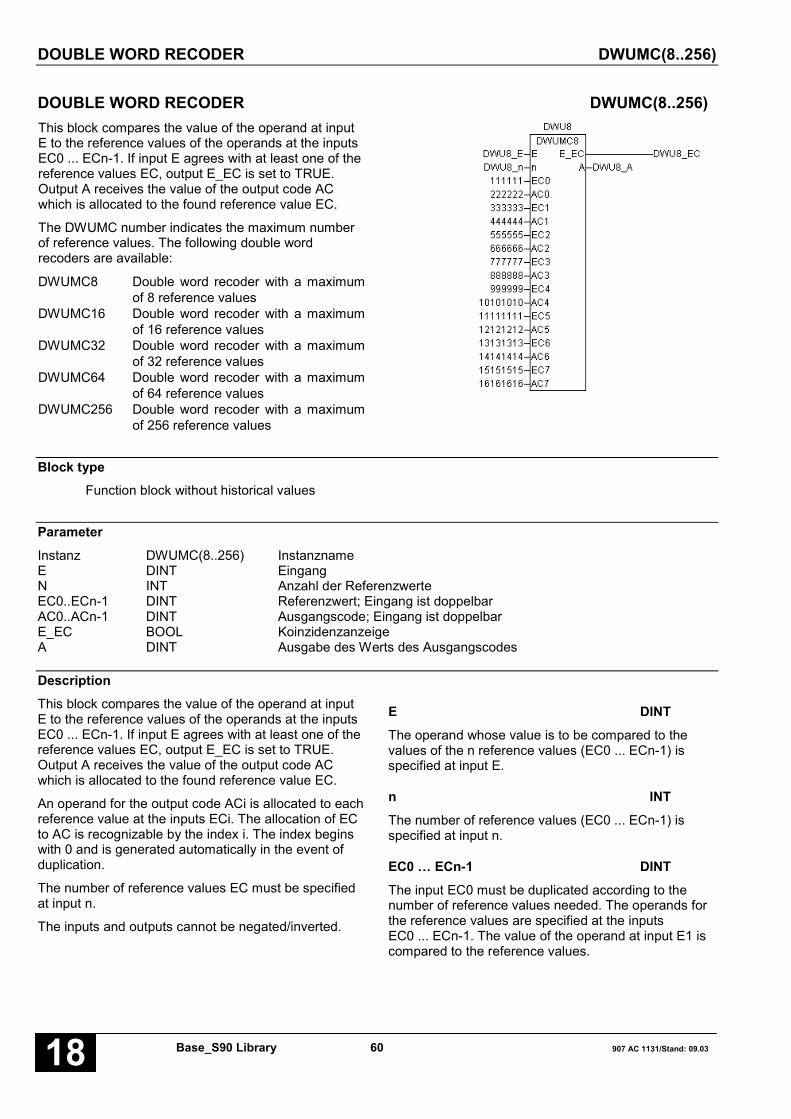
DOUBLE WORD RECODER DWUMC(8..256)
Base_S90 Library 60 907 AC 1131/Stand: 09.0318
DOUBLE WORD RECODER DWUMC(8..256)This block compares the value of the operand at inputE to the reference values of the operands at the inputsEC0 ... ECn-1. If input E agrees with at least one of thereference values EC, output E_EC is set to TRUE.Output A receives the value of the output code ACwhich is allocated to the found reference value EC.
The DWUMC number indicates the maximum numberof reference values. The following double wordrecoders are available:
DWUMC8 Double word recoder with a maximumof 8 reference values
DWUMC16 Double word recoder with a maximumof 16 reference values
DWUMC32 Double word recoder with a maximumof 32 reference values
DWUMC64 Double word recoder with a maximumof 64 reference values
DWUMC256 Double word recoder with a maximumof 256 reference values
Block typeFunction block without historical values
ParameterInstanz DWUMC(8..256) InstanznameE DINT EingangN INT Anzahl der ReferenzwerteEC0..ECn-1 DINT Referenzwert; Eingang ist doppelbarAC0..ACn-1 DINT Ausgangscode; Eingang ist doppelbarE_EC BOOL KoinzidenzanzeigeA DINT Ausgabe des Werts des Ausgangscodes
DescriptionThis block compares the value of the operand at inputE to the reference values of the operands at the inputsEC0 ... ECn-1. If input E agrees with at least one of thereference values EC, output E_EC is set to TRUE.Output A receives the value of the output code ACwhich is allocated to the found reference value EC.
An operand for the output code ACi is allocated to eachreference value at the inputs ECi. The allocation of ECto AC is recognizable by the index i. The index beginswith 0 and is generated automatically in the event ofduplication.
The number of reference values EC must be specifiedat input n.
The inputs and outputs cannot be negated/inverted.
E DINTThe operand whose value is to be compared to thevalues of the n reference values (EC0 ... ECn-1) isspecified at input E.
n INTThe number of reference values (EC0 ... ECn-1) isspecified at input n.
EC0 … ECn-1 DINTThe input EC0 must be duplicated according to thenumber of reference values needed. The operands forthe reference values are specified at the inputsEC0 ... ECn-1. The value of the operand at input E1 iscompared to the reference values.
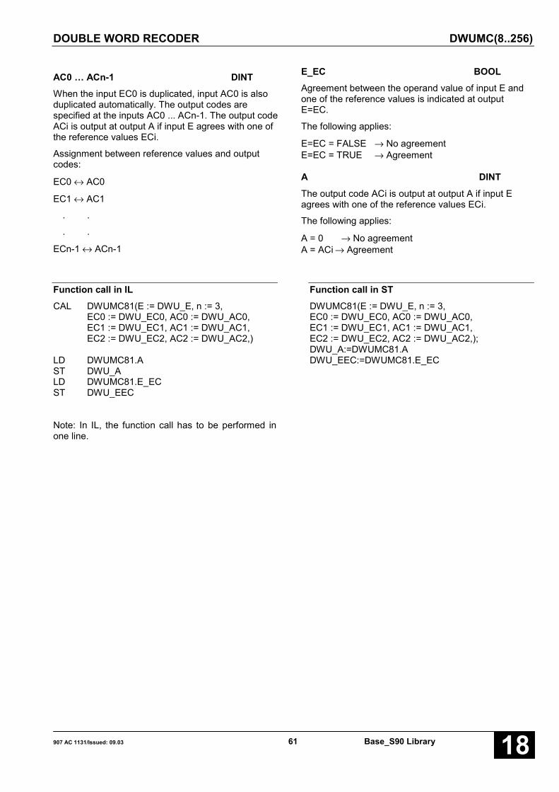
DOUBLE WORD RECODER DWUMC(8..256)
907 AC 1131/Issued: 09.03 61 Base_S90 Library 18
AC0 … ACn-1 DINTWhen the input EC0 is duplicated, input AC0 is alsoduplicated automatically. The output codes arespecified at the inputs AC0 ... ACn-1. The output codeACi is output at output A if input E agrees with one ofthe reference values ECi.
Assignment between reference values and outputcodes:
EC0 ↔ AC0
EC1 ↔ AC1
. .
. .
ECn-1 ↔ ACn-1
E_EC BOOLAgreement between the operand value of input E andone of the reference values is indicated at outputE=EC.
The following applies:
E=EC = FALSE → No agreementE=EC = TRUE → Agreement
A DINTThe output code ACi is output at output A if input Eagrees with one of the reference values ECi.
The following applies:
A = 0 → No agreementA = ACi → Agreement
Function call in ILCAL DWUMC81(E := DWU_E, n := 3,
EC0 := DWU_EC0, AC0 := DWU_AC0,EC1 := DWU_EC1, AC1 := DWU_AC1,EC2 := DWU_EC2, AC2 := DWU_AC2,)
LD DWUMC81.AST DWU_ALD DWUMC81.E_ECST DWU_EEC
Note: In IL, the function call has to be performed inone line.
Function call in STDWUMC81(E := DWU_E, n := 3,EC0 := DWU_EC0, AC0 := DWU_AC0,EC1 := DWU_EC1, AC1 := DWU_AC1,EC2 := DWU_EC2, AC2 := DWU_AC2,);DWU_A:=DWUMC81.ADWU_EEC:=DWUMC81.E_EC

DOUBLE WORD TO WORD CONVERSION DWW
Base_S90 Library 62 907 AC 1131/Stand: 09.0318
DOUBLE WORD TO WORD CONVERSION DWWThe value of the double word operand at input E isconverted to a word variable and the result is assignedto the word operand at output A1.
Block typeFunction block without historical values
ParametersInstance DWW Instance nameE DINT Double word variable to be convertedA1 INT Result of conversion, word variableA2 BOOL Result limited
DescriptionThe value of the double word operand at input E1 isconverted to a word variable and the result is assignedto the word operand at output A1.
The result is limited to the maximum or minimumnumber range.
max. number range: +32767 (7FFFH)min. number range: -32767 (8001H)
If limiting occurred, a TRUE signal is assigned to thebinary operand at output A2. If no limiting occurred, aFALSE signal is assigned to the binary operand atoutput A2.
The input and the outputs can neither be duplicated nornegated.
Function call in ILCAL DWW1(E := DWW_E)
LD DWW1.A2ST DWW_A2LD DWW1.A1ST DWW_A1
Function call in STDWW1(E := DWW_E);DWW_A2:=DWW1.A2;DWW_A1:=DWW1.A1;
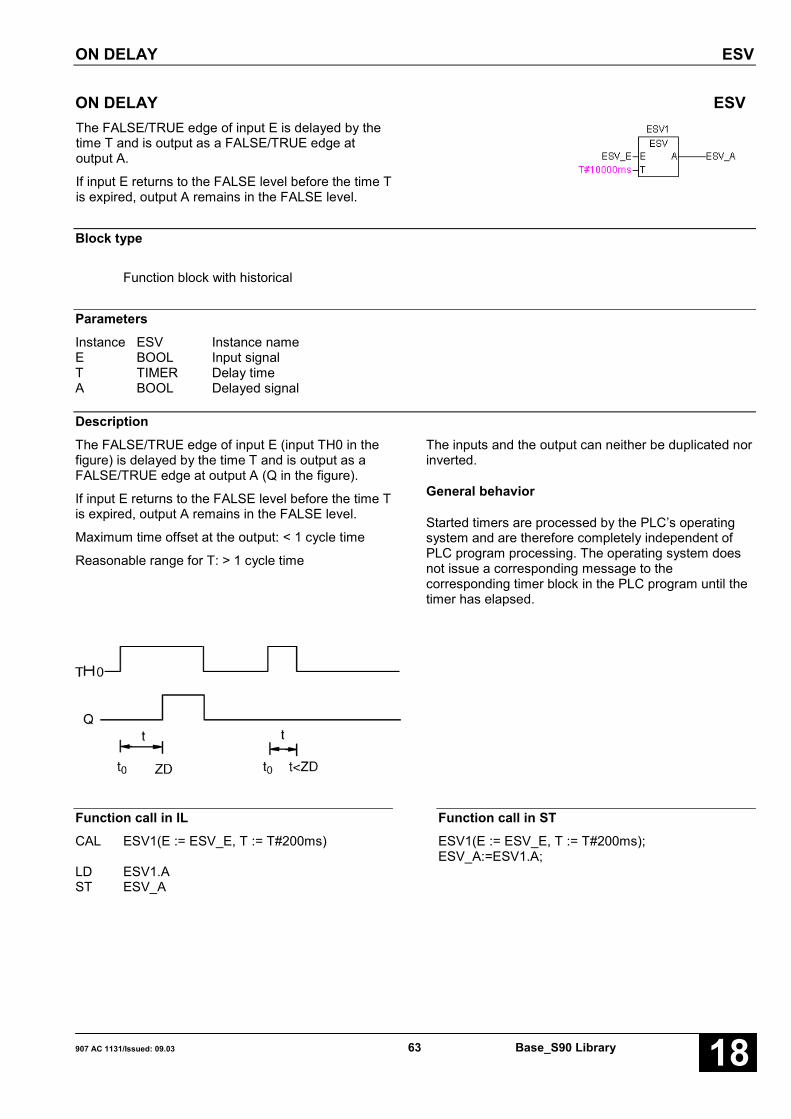
ON DELAY ESV
907 AC 1131/Issued: 09.03 63 Base_S90 Library 18
ON DELAY ESVThe FALSE/TRUE edge of input E is delayed by thetime T and is output as a FALSE/TRUE edge atoutput A.
If input E returns to the FALSE level before the time Tis expired, output A remains in the FALSE level.
Block type
Function block with historical
ParametersInstance ESV Instance nameE BOOL Input signalT TIMER Delay timeA BOOL Delayed signal
DescriptionThe FALSE/TRUE edge of input E (input TH0 in thefigure) is delayed by the time T and is output as aFALSE/TRUE edge at output A (Q in the figure).
If input E returns to the FALSE level before the time Tis expired, output A remains in the FALSE level.
Maximum time offset at the output: < 1 cycle time
Reasonable range for T: > 1 cycle time
The inputs and the output can neither be duplicated norinverted.
General behavior
Started timers are processed by the PLC’s operatingsystem and are therefore completely independent ofPLC program processing. The operating system doesnot issue a corresponding message to thecorresponding timer block in the PLC program until thetimer has elapsed.
Function call in ILCAL ESV1(E := ESV_E, T := T#200ms)
LD ESV1.AST ESV_A
Function call in STESV1(E := ESV_E, T := T#200ms);ESV_A:=ESV1.A;

STACK MEMORY FIRST IN FIRST OUT, BINARY FIFOB
Base_S90 Library 64 907 AC 1131/Stand: 09.0318
STACK MEMORY FIRST IN FIRST OUT, BINARY FIFOBThe function block realizes astack memory for binary datafrom which the data written infirst are again read out first (firstin/first out).
Block typeFunction block with historical values
ParametersInstance FIFOB Instance nameLADE BOOL Load FIFOLESE BOOL Read FIFORESET BOOL Reset FIFO, FALSE→TRUE edgeIE BOOL Input of data in the FIFOANZ INT Number of memory locations (bytes)ANF DWORD Start address of the FIFO in the flag areaA BOOL Output of data from the FIFOFST INT Filling level of the FIFOLEER BOOL FIFO emptyVOLL BOOL FIFO full
DescriptionThe function block realizes a stack memory for binarydata from which the data written in first are again readout first (first in/first out).
The inputs and outputs can neither be duplicated nornegated/inverted.
LADE BOOLThe value present at input E is transferred to the nextfree position of the FIFO by means of a TRUE signal atinput LADE. If the FIFO is "full" and a "load" signal ispresent, the new value will not be read in. A new valuecan only be read if a value has been read out first. It isthen transferred to the first position of the FIFO.
LESE BOOLA TRUE signal at input LESE results in the output ofthe current FIFO value through output A. If the FIFO is"empty", a pending read order is ignored and the valueFALSE is applied at output A. Output A is always set toFALSE if there is no read order.
LADE and LESEIf load and read orders are present simultaneously andthe FIFO is empty, the value to be loaded is forwardeddirectly from input E to output A. If the FIFO is notempty, the current FIFO value is output and the newload information is transferred to it. The FIFO does notchange its filling level in this operating mode. The valueoutput through output FST remains constant. If theFIFO is empty, output LEER remains TRUE and outputFST is set to 0.
RESET BOOLA FALSE -> TRUE edge at input RESET results in thereset of the block. Therefore, values read in before areno longer available.
Output LEER is set to TRUE and the outputs FST andA are set to 0 (FALSE).

STAPELSPEICHER FIRST-IN-FIRST-OUT, BINÄR FIFOB
907 AC 1131/Issued: 09.03 65 Base_S90 Library 18
RESET and LADEIf RESET and LADE signals are present simultaneouslythe reset is performed first and then directly afterwardsthe load operation. Therefore, the FIFO is reset and thenew value to be read in is then immediately stored inthe FIFO as the first value.
RESET and LADE and LESEThe value at input E is forwarded directly to output A.Output LEER is set permanently to TRUE and outputFST is set permanently to 0.
E BOOLThe value to be transferred into the FIFO is specified atinput E.
ANZ INTThe number of required memory locations (bytes) ofthe FIFO is specified at input ANZ. The number ofmemory locations corresponds to the number of binaryvalues to be stored.
ANF DWORDThe FIFO memory start address is specified as a binaryflag at input ANF. The block ADR provides thecorresponding binary flag address. The FIFO beginswith the specified flag.
A BOOLWhen reading the FIFO, the current value is availableat output A. If no read order is available, the valueFALSE is output.
FST INTOutput FST indicates the current filling level of theFIFO at any time. The filling level is the number ofbinary values stored in the FIFO.
LEER BOOLThe output LEER indicates whether or not the FIFO isempty.
LEER = FALSE → FIFO is not emptyLEER = TRUE → FIFO is empty
VOLL BOOLThe output VOLL indicates whether or not the FIFO isfull.
VOLL = FALSE → FIFO is not fullVOLL = TRUE → FIFO is full
No further values can be read in if the FIFO is full. Anew value can only be read in after a value has beenread out. The new value is positioned to the beginningof the FIFO.
Function call in ILLD FIFO_ANFADRST FIFOB1.ANF
CAL FIFOB1(LADE := FIFO_LADE,LESE := FIFO_LESE, RESET := FIFO_RES,E := FIFO_E, ANZ := FIFO_ANZ)
LD FIFOB1.FSTST FIFO_FSTLD FIFOB1.LEERST FIFO_LEERLD FIFOB1.VOLLST FIFO_VOLLLD FIFOB1.AST FIFO_A
Note: In IL, the function call has to be performed inone line.
Function call in STFIFOB1.ANF := ADR(FIFO_ANF);FIFOB1(LADE := FIFO_LADE, LESE := FIFO_LESE,RESET := FIFO_RES, E := FIFO_E,ANZ := FIFO_ANZ);FIFO_FST:=FIFOB1.FST;FIFO_LEER:=FIFOB1.LEER;FIFO_VOLL:=FIFOB1.VOLL;FIFO_A:=FIFOB1.A;
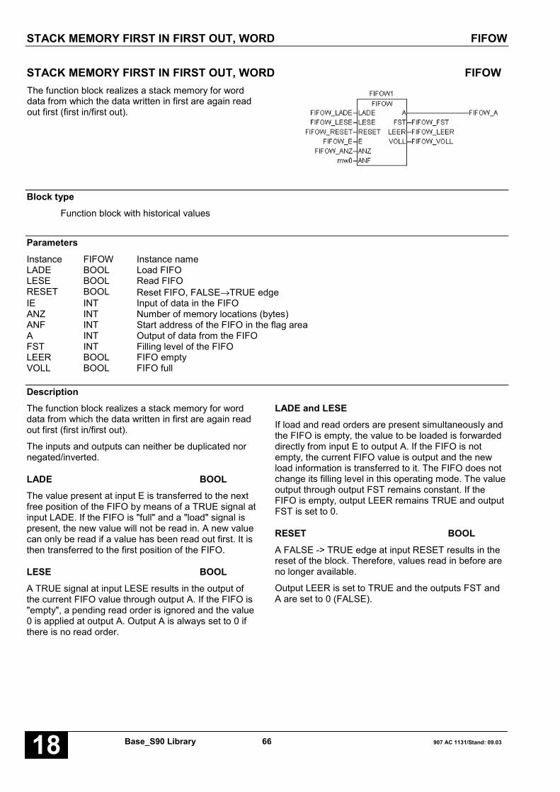
STACK MEMORY FIRST IN FIRST OUT, WORD FIFOW
Base_S90 Library 66 907 AC 1131/Stand: 09.0318
STACK MEMORY FIRST IN FIRST OUT, WORD FIFOWThe function block realizes a stack memory for worddata from which the data written in first are again readout first (first in/first out).
Block typeFunction block with historical values
ParametersInstance FIFOW Instance nameLADE BOOL Load FIFOLESE BOOL Read FIFORESET BOOL Reset FIFO, FALSE→TRUE edgeIE INT Input of data in the FIFOANZ INT Number of memory locations (bytes)ANF INT Start address of the FIFO in the flag areaA INT Output of data from the FIFOFST INT Filling level of the FIFOLEER BOOL FIFO emptyVOLL BOOL FIFO full
DescriptionThe function block realizes a stack memory for worddata from which the data written in first are again readout first (first in/first out).
The inputs and outputs can neither be duplicated nornegated/inverted.
LADE BOOLThe value present at input E is transferred to the nextfree position of the FIFO by means of a TRUE signal atinput LADE. If the FIFO is "full" and a "load" signal ispresent, the new value will not be read in. A new valuecan only be read if a value has been read out first. It isthen transferred to the first position of the FIFO.
LESE BOOLA TRUE signal at input LESE results in the output ofthe current FIFO value through output A. If the FIFO is"empty", a pending read order is ignored and the value0 is applied at output A. Output A is always set to 0 ifthere is no read order.
LADE and LESEIf load and read orders are present simultaneously andthe FIFO is empty, the value to be loaded is forwardeddirectly from input E to output A. If the FIFO is notempty, the current FIFO value is output and the newload information is transferred to it. The FIFO does notchange its filling level in this operating mode. The valueoutput through output FST remains constant. If theFIFO is empty, output LEER remains TRUE and outputFST is set to 0.
RESET BOOLA FALSE -> TRUE edge at input RESET results in thereset of the block. Therefore, values read in before areno longer available.
Output LEER is set to TRUE and the outputs FST andA are set to 0 (FALSE).
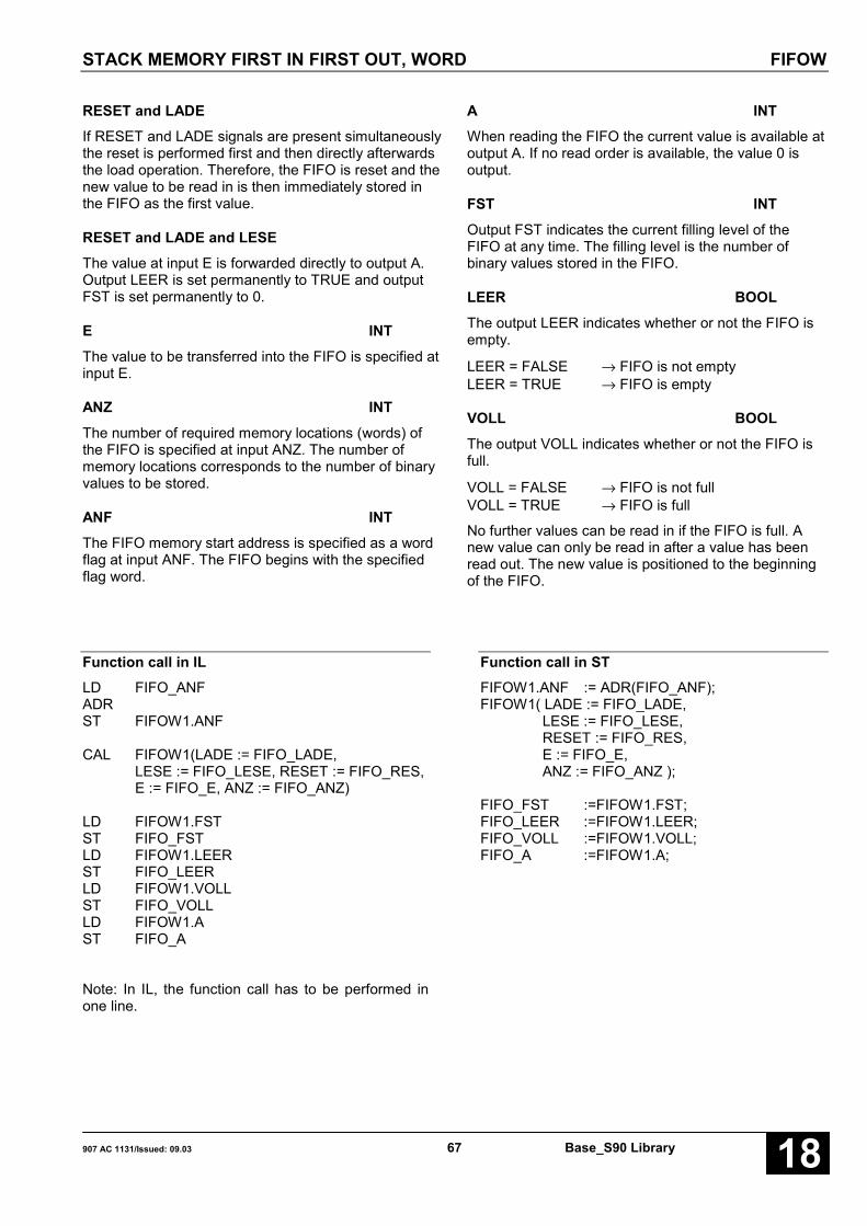
STACK MEMORY FIRST IN FIRST OUT, WORD FIFOW
907 AC 1131/Issued: 09.03 67 Base_S90 Library 18
RESET and LADEIf RESET and LADE signals are present simultaneouslythe reset is performed first and then directly afterwardsthe load operation. Therefore, the FIFO is reset and thenew value to be read in is then immediately stored inthe FIFO as the first value.
RESET and LADE and LESEThe value at input E is forwarded directly to output A.Output LEER is set permanently to TRUE and outputFST is set permanently to 0.
E INTThe value to be transferred into the FIFO is specified atinput E.
ANZ INTThe number of required memory locations (words) ofthe FIFO is specified at input ANZ. The number ofmemory locations corresponds to the number of binaryvalues to be stored.
ANF INTThe FIFO memory start address is specified as a wordflag at input ANF. The FIFO begins with the specifiedflag word.
A INTWhen reading the FIFO the current value is available atoutput A. If no read order is available, the value 0 isoutput.
FST INTOutput FST indicates the current filling level of theFIFO at any time. The filling level is the number ofbinary values stored in the FIFO.
LEER BOOLThe output LEER indicates whether or not the FIFO isempty.
LEER = FALSE → FIFO is not emptyLEER = TRUE → FIFO is empty
VOLL BOOLThe output VOLL indicates whether or not the FIFO isfull.
VOLL = FALSE → FIFO is not fullVOLL = TRUE → FIFO is full
No further values can be read in if the FIFO is full. Anew value can only be read in after a value has beenread out. The new value is positioned to the beginningof the FIFO.
Function call in ILLD FIFO_ANFADRST FIFOW1.ANF
CAL FIFOW1(LADE := FIFO_LADE,LESE := FIFO_LESE, RESET := FIFO_RES,E := FIFO_E, ANZ := FIFO_ANZ)
LD FIFOW1.FSTST FIFO_FSTLD FIFOW1.LEERST FIFO_LEERLD FIFOW1.VOLLST FIFO_VOLLLD FIFOW1.AST FIFO_A
Note: In IL, the function call has to be performed inone line.
Function call in STFIFOW1.ANF := ADR(FIFO_ANF);FIFOW1( LADE := FIFO_LADE,
LESE := FIFO_LESE,RESET := FIFO_RES,E := FIFO_E,ANZ := FIFO_ANZ );
FIFO_FST :=FIFOW1.FST;FIFO_LEER :=FIFOW1.LEER;FIFO_VOLL :=FIFOW1.VOLL;FIFO_A :=FIFOW1.A;

FUNCTION GENERATOR FKG(2..256)
Base_S90 Library 68 907 AC 1131/Stand: 09.0318
FUNCTION GENERATOR FKG(2..256)In an x/y coordinate system, a polygon is defined by ncoordinate points X0/Y0...Xn-1/Yn-1. For each value atinput x, the function block outputs the assigned y valueof the polygon at output y.
The FKG number indicates the maximum number ofpoints. The following function generators are available:
FKG2 Function generator with max. 2 pointsFKG4 Function generator with max. 4 pointsFKG16 Function generator with max. 16 pointsFKG32 Function generator with max. 32 pointsFKG64 Function generator with max. 64 nodesFKG256 Function generator with max. 256 points
Block typeFunction block without historical values
ParametersInstance FKG(2..256) Instance nameX INT Input for the x value of the polygonN INT Number of pointsXC0..XCn-1 INT Input for x-values of the pointsYC0..YCn-1 INT Input for y-values of the pointsY INT Output for the y value of the polygon
DescriptionThe FKG number indicates the maximum number ofpoints. The following function generators are available:
FKG2 Function generator with max. 2 pointsFKG4 Function generator with max. 4 pointsFKG16 Function generator with max. 16 pointsFKG32 Function generator with max. 32 pointsFKG64 Function generator with max. 64 pointsFKG256 Function generator with max. 256 points
In an x/y coordinate system, a polygon is defined by ncoordinate points X0/Y0...Xn-1/Yn-1. For each value atinput x, the function block outputs the assigned y valueof the polygon at output y.
To the x-coordinate is valid:
X0 < X1 < X2 … < Xn-12 ≤ n ≤ FKG number
Example:For FKG16, the following applies: 2 ≤ n ≤ 16
The block performs a linear interpolation between thepoints. The resulting polygon represents the connectionbetween the input value x and the output value y.
For the interpolation between two points the followingapplies:
(x - Xi-1) * (Yi - Yi-1)y = ––––––––––––––––– + Yi-1
Xi - Xi-1
Notes:
At the division it is always rounded down, i.e. aremainder with the division is not considered.
Die difference between two points may amount to max.32767.
For the range outside of the nodes the followingapplies:
for x < X0, y = Y0for x > Xn-1, y = Yn-1

FUNCTION GENERATOR FKG(2..256)
907 AC 1131/Issued: 09.03 69 Base_S90 Library 18
x INTThe current x coordinate is specified at input x. Theblock then defines the y coordinate assigned by thepolygon.
n INTThe number of nodes which are necessary to definethe polygon is specified at input n.
XC0-…-XCn-1 INTThe x coordinates of the n nodes are specified at theinputs XC0 ... XCn-1.
YC0-…-YCn-1 INTThe y coordinates of the n nodes are specified at theinputs YC0 ... YCn-1.
y INTThe y coordinate assigned by the polygon of thespecified x coordinate is output at output y.
Function call in ILCAL FKG21(X := FKG_X, n := 2,
XC0 := FKG_XC0, YC0 := FKG_YC0,XC1 := FKG_XC1, YC1 := FKG_YC1)
LD FKG21.YST FKG_Y
Note: In IL, the function call has to be performed inone line.
Function call in STFKG21(X := FKG_X,
n := 2,XC0 := FKG_XC0,YC0 := FKG_YC0,XC1 := FKG_XC1,YC1 := FKG_YC1);
FKG_Y:=FKG21.Y;

RAMP FUNCTION GENERATOR HLG
Base_S90 Library 70 907 AC 1131/Stand: 09.0318
RAMP FUNCTION GENERATOR HLGThe ramp function generator is used for the ramp-shaped adaption of the current actual value at theoutput to a specified set point.
The value at the HLG output is adapted linearly fromthe current actual value to the specified set point withthe slope y’.
In doing so, the value at the output precisely runsthrough the amount of the set point during the time THor TR. If the value at the HLG output has reached theset point, it no longer changes unless a new set point isspecified.
Block typeFunction block with historical values
ParametersInstance HLG Instance nameE01 BOOL Selection of the set point 0 or set point 1S0 INT Set point 0S1 INT Set point 1TH_T INT Start up time scaled to the cycle timeTR_T INT Return time scaled to the cycle timeSTOP BOOL Latching the output at the current valueS BOOL Setting the output to the INIT valueINIT INT INIT value to which the output can be setR BOOL Reset the output to value 0A INT Output
DescriptionThe ramp function generator is used for the ramp-shaped adaption of the current actual value at theoutput to a specified set point.
The value at the HLG output is adapted linearly fromthe current actual value to the specified set point withthe slope y’.
In doing so, the value at the output precisely runsthrough the amount of the set point during the time THor TR. If the value at the HLG output has reached theset point, it no longer changes unless a new set point isspecified.
The inputs and the output can neither be duplicated nornegated/inverted.
The slope y’ of the ramp results from the specified timeTH (start up time) or TR (return time) and the amount ofthe set point:
Set point amountSlope y’ = –––––––––––––
TH or TR
The slope is
• positive, if set point > actual value
• negative, if set point < actual value
• 0, if set point = 0
Therefore, the specified set point has two functions
– its amount defines the slope of the ramp inconjunction with the specified time TH or TR;
– it represents the value to which the current actualvalue must be adapted in a ramp shape.
The user can specify the start up time TH and thereturn time TR separately. The direction of the slope isdefined on the basis of the set point. The direction ofthe slope then defines whether or not the running timeTH or TR is used.
Slope y’ positive → TH, i.e. the ramp runs upwards.Slope y’ negative → TR, i.e. the ramp runs downwards.
The start up time TH and the return time TR must bescaled to the program cycle time TZ, i.e. the followingmust be specified at the corresponding block inputs:

RAMP FUNCTION GENERATOR HLG
907 AC 1131/Issued: 09.03 71 Base_S90 Library 18
– Start up time: TH/TZ– Return time: TR/TZ
The times are specified in milliseconds. The followingapplies to the time constants TH or TR:
0 < TH < 327670 < TR < 32767
Two set points can be planned (S0 and S1), wherebyone of these set points is selected by the binary inputE01 (set point selection).
The set points can assume the following values:-32767 < set point < +32767
At any time, the output of the ramp function generatorcan be– stopped at the current value– set to an initial value– reset (output = 0)
The STOP input has the highest priority and the R inputhas the lowest.
The values at the HLG inputs can be changed at anytime in the user program. In this way, any (non-linear)adaption to the set point can be realized on the basis ofthe linear adaption of the actual value.
Caution:Set point = 0 means that the slope of the ramp is also0, i. e. the current actual value does not change. If it isintended to switch from an actual value unequal to 0 toan actual value of 0, a set point unequal to 0 must bespecified and the output of the ramp function generatormust be limited to 0 by a subsequent limiter. (Oninterpolation, the rounding transitions are based oncalculation of integral numbers only).
E01 BOOLOne of the two set points is selected with input E01.
E01 = FALSE → set point S0E01 = TRUE → set point
S0 INTThe set point 0 is specified at input S0.
S1 INTThe set point 0 is specified at input S0.
TH_T INTThe start up time is specified at input TH_T. At thesame time, the start up time TH must be scaled to thecycle time T.
TR_T INTThe start up time is specified at input TH_T. At thesame time, the start up time TR must be scaled to thecycle time T.
STOP BOOLThe output can be latched to the current value bymeans of the STOP input.
STOP = FALSE → Output not latchedSTOP = TRUE → Output is latched
The STOP input has higher priority than the inputs Sand R.
S BOOLWith input S, the output can be set to the initial valuespecified at input INIT.
S = FALSE → Output is not set to initial value.S = TRUE → Output is set to initial value.
INIT INTThe initial value to which the output is to be set ifrequired is specified at input INIT.
R BOOLThe output can be set to the value 0 with the input R.
R = FALSE → Output is not resetR = TRUE → Output is reset to value 0.
A INTOutput of the block.

RAMP FUNCTION GENERATOR HLG
Base_S90 Library 72 907 AC 1131/Stand: 09.0318
Example 1:The actual value is to be changed from 0 to the set point +500 (set point amount 500) and then from +500 to theset point -1000 (set point amount 1000).
The start up time is TH and the return time TR.0 S: 500
1 S: -1000
TR(*) is the actual time until the actual value has reached -1000. During the time TH or TR, the actual valuechanges by the amount of the applied set point.
Example 2:
The actual value is to be changed from 0 to the set point +500 (set point amount 500) and then from +500 to theset point 1500 (set point amount 1500).
The start up time is TH and the return time TR.
0 S: 5001 S: 1500
TR(*) is the actual time until the actual value has reached 1500. During the time TH or TR, the actual valuechanges by the amount of the applied set point.

RAMP FUNCTION GENERATOR HLG
907 AC 1131/Issued: 09.03 73 Base_S90 Library 18
Function call in ILCAL HLG1(E01 := HLG_E01, S0 := HLG_S0,
S1 := HLG_S1, TH_T := HLG_THT,TR_T := HLG_TRT, STOP := HLG_STOP,SET := HLG_SET, INIT := HLG_INIT,RESET := HLG_RES)
LD HLG1.AST HLG_A
Note: In IL, the function call has to be performed inone line.
Function call in STHLG1(E01 := HLG_E01, S0 := HLG_S0,S1 := HLG_S1, TH_T := HLG_THT,TR_T := HLG_TRT, STOP := HLG_STOP,SET := HLG_SET, INIT := HLG_INIT,RESET := HLG_RES);HLG_A:=HLG1.A;

READ BINARY VARIABLE, INDEXED IDLB
Base_S90 Library 74 907 AC 1131/Stand: 09.0318
READ BINARY VARIABLE, INDEXED IDLBThe function block servesfor the purpose of indexedreading of binary variables.
Block typeFunction block without historical values
ParametersInstance IDLB Instance nameFREI BOOL Block enabling
Frei = FALSE: Block is not processedFrei = TRUE: The value of the source variable is read andassigned to the target variable.
INDEX INT The index and the basic variable result in the source variableBASIS DWORD Basic address of the binary variableZIEL BOOL Target variable
DescriptionThe function block serves for the purpose of indexedreading of binary variables.
The source variable to be read is obtained fromindexing the basic variable. The value of the sourcevariable read is assigned to the target variable.
Note:The basic variable must be either an addressablevariable (%MX.., %IX.., %QX..) or an ARRAY. All othervariables are freely defined by the system andtherefore have no definite order.
The inputs and outputs can neither be duplicated norinverted nor negated.
FREI BOOLBlock enabling
FREI = FALSE→ Block is not processed
FREI = TRUE→ The value of the source variable is read andassigned to the target variable ZIEL.
INDEX INTThe index value is specified at input INDEX. Thesource variable results from the index and the basicvariable.
Value range: -16383 < INDEX < +16383
If INDEX is not within this range, the function block isnot processed.
BASIS DWORDThe basic variable is specified at input BASIS. Theblock ADR provides the corresponding binary flagaddress. The source variable results from the indexand the basic variable.
ZIEL BOOLThe target variable is specified at output ZIEL. Thevalue of the selected source variable is assigned to thetarget variable ZIEL.

READ BINARY VARIABLE, INDEXED IDLB
907 AC 1131/Issued: 09.03 75 Base_S90 Library 18
Function call in ILLD IDLB_BASADRST IDLB1.BASISCAL IDLB1(FREI := IDLB_FREI,
INDEX := IDLB_INDEX)
LD IDLB1.ZIELST IDLB_ZIEL
Note: In IL, the function call has to be performed inone line.
Function call in STIDLB1.BASIS := ADR(IDLB_BAS);IDLB1(FREI := IDLB_FREI, INDEX := IDLB_INDEX);IDLB_ZIEL:=IDLB1.ZIEL;

READ WORD VARIABLE, INDEXED IDLM
Base_S90 Library 76 907 AC 1131/Stand: 09.0318
READ WORD VARIABLE, INDEXED IDLMThe function block serves for the purpose of indexedreading of word variables.
Block typeFunction block without historical values
ParametersInstance IDLm Instance nameFREI BOOL Block enabling
Frei = FALSE: Block is not processedFrei = TRUE: The value of the source variable is read and assigned tothe target variable.
INDEX INT The index and the basic variable result in the source variableBASIS INT Basic variableZIEL INT Target variable
DescriptionThe function block serves for the purpose of indexedreading of word variables.
The source variable to be read is obtained fromindexing the basic variable. The value of the sourcevariable read is assigned to the target variable.
Note:The basic variable must be either an addressablevariable (%MW.., %IW.., %QW..) or an ARRAY. Allother variables are freely defined by the system andtherefore have no definite order.
The inputs and outputs can neither be duplicated norinverted nor negated.
FREI BOOLBlock enabling
FREI = FALSE→ Block is not processed
FREI = TRUE→ The value of the source variable is read andassigned to the target variable ZIEL.
INDEX INTThe index value is specified at input INDEX. Thesource variable results from the index and the basicvariable.
Value range: -32767 < INDEX < +32767
If INDEX is not within this range, the function block isnot processed.
BASIS INTThe basic variable is specified at input BASIS. Thesource variable results from the index and the basicvariable.
ZIEL INTThe target variable is specified at output ZIEL. Thevalue of the selected source variable is assigned to thetarget variable ZIEL.

READ WORD VARIABLE, INDEXED IDLM
907 AC 1131/Issued: 09.03 77 Base_S90 Library 18
Function call in ILCAL IDLM1(FREI := IDLM_FREI,
INDEX := IDLM_INDEX,BASIS := IDLM_BAS)
LD IDLM1.ZIELST IDLM_ZIELNote: In IL, the function call has to be performed inone line.
Function call in STIDLM1(FREI := IDLM_FREI, INDEX := IDLM_INDEX,BASIS := IDLM_BAS);IDLM_ZIEL:=IDLM1.ZIEL;

WRITE BINARY VARIABLE, INDEXED IDSB
Base_S90 Library 78 907 AC 1131/Stand: 09.0318
WRITE BINARY VARIABLE, INDEXED IDSBThe function block serves for the purpose of indexedwriting of binary variables.
Block typeFunction block without historical values
ParametersInstance IDSB Instance nameFREI BOOL Block enabling
Frei = FALSE: Block is not processedFrei = TRUE: The value of the source variable is read andassigned to the target variable.
QUELL BOOL Source variableINDEX INT The index and the basic variable result in the source variableBASIS DWORD Basic address of the binary variable
DescriptionThe function block serves for the purpose of indexedwriting of binary variables.
When the block is enabled, the value of the sourcevariable is read and assigned to the target variable.The target variable is defined by indexing the basicvariable.
Note:The basic variable must be either an addressablevariable (%MX.., %IX.., %QX..) or an ARRAY. All othervariables are freely defined by the system andtherefore have no definite order.
The inputs and outputs can neither be duplicated norinverted nor negated.
FREI BOOLBlock enabling
FREI = FALSE→ Block is not processed
FREI = TRUE→ The value of the source variable is read andassigned to the target variable.
QUELL BOOLThe source variable is specified at input QUELL. Thevalue of this variable is read and assigned to the targetvariable.
INDEX INTThe index value is specified at input INDEX. Thesource variable results from the index and the basicvariable.
Value range: -16383 < INDEX < +16383
If INDEX is not within this range, the function block isnot processed.
BASIS DWORDThe basic variable is specified at input BASIS. Theblock ADR provides the corresponding binary flagaddress. The source variable results from the indexand the basic variable.

WRITE BINARY VARIABLE, INDEXED IDSB
907 AC 1131/Issued: 09.03 79 Base_S90 Library 18
Function call ILLD IDSB_BASADRST IDSB1.BASISCAL IDSB1(FREI := IDSB_FREI,
QUELL := IDSB_QUELL,INDEX := IDSB_INDEX)
Note: In IL, the function call has to be performed inone line.
Function call in STIDSB1.BASIS := ADR(IDSB_BAS);IDSB1(FREI := IDSB_FREI,QUELL := IDSB_QUELL, INDEX := IDSB_INDEX);

WRITE WORD VARIABLE, INDEXED IDSM
Base_S90 Library 80 907 AC 1131/Stand: 09.0318
WRITE WORD VARIABLE, INDEXED IDSMThe function block serves for the purpose of indexedwriting of word variables.
Block typeFunction block without historical values
ParametersInstance IDSm Instance nameFREI BOOL Block enabling
Frei = FALSE: Block is not processedFrei = TRUE: The value of the source variable is read and assigned tothe target variable.
QUELL INT Source variableINDEX INT The index and the basic variable result in the source variableBASIS INT Basic variable
DescriptionThe function block serves for the purpose of indexedwriting of word variables.
When the block is enabled, the value of the sourcevariable is read and assigned to the target variable.The target variable is defined by indexing the basicvariable.
Note:The basic variable must be either an addressablevariable (%MW.., %IW.., %QW..) or an ARRAY. Allother variables are freely defined by the system andtherefore have no definite order.
The inputs and outputs can neither be duplicated norinverted nor negated.
FREI BOOLBlock enabling
FREI = FALSE→ Block is not processed
FREI = TRUE→ The value of the source variable is read andassigned to the target variable.
QUELL INTThe source variable is specified at input QUELL. Thevalue of this variable is read and assigned to the targetvariable.
INDEX INTThe index value is specified at input INDEX. Thesource variable results from the index and the basicvariable.
Value range: -32767 < INDEX < +32767
If INDEX is not within this range, the function block isnot processed.
BASIS INTThe basic variable is specified at input BASIS. Thesource variable results from the index and the basicvariable.

WRITE WORD VARIABLE, INDEXED IDSM
907 AC 1131/Issued: 09.03 81 Base_S90 Library 18
Function call in ILCAL IDSM1(FREI := IDSM_FREI,
QUELL := IDSM_QUELL,INDEX := IDSM_INDEX,BASIS := IDSM_BAS)
Note: In IL, the function call has to be performed inone line.
Function call in STIDSM1(FREI := IDSM_FREI,QUELL := IDSM_QUELL, INDEX := IDSM_INDEX,BASIS := IDSM_BAS);

INITIALIZE MEMORY AREA IN THEBINARY OPERAND MEMORY WITH ZERO INITSB
Base_S90 Library 82 907 AC 1131/Stand: 09.0318
INITIALIZE MEMORY AREA IN THEBINARY OPERAND MEMORY WITH ZERO INITSBThe function block serves for the purpose of bitwiseinitialization of memory areas in the operand memorywith the value 0.
Block typeFunction block with historical values
ParametersInstance INITSB Instance nameFREI BOOL Enabling for non-recurring processing of the block (FALSE/TRUE
edge)N INT Number (n) of memory bits to be initializedSVAR DWORD The n memory bits specified at input n are initialized as from this
variable.
DescriptionThe function block serves for the purpose of bit-wiseinitialization of memory areas in the operand memorywith the value 0.
The block is run through precisely once in the event ofa FALSE/TRUE edge at input FREI. In doing so, nmemory bits are initialized with 0 starting from thevariable specified at input VAR.
FREI BOOLBlock enabling. The block is run through precisely oncein the event of a FALSE/TRUE edge at this input.
N INTNumber (n) of bit operands to be initialized (bit orBOOL). The number of bit operands to be initialized isspecified at this input.
Value range: 0 < n < 32767
No initialization is performed if the value 0 is applied.
SVAR DWORDBeginning from this variable address (inclusive), nmemory bits are initialized with the value 0. The blockADR provides the corresponding binary flag address.
Function call in ILLD INSB_SVARADRST INITSB.SVARCAL INITSB(FREI := INSB_FREI, N := INSB_N)
Function call in STINITSB.SVAR := ADR(INSB_SVAR);INITSB(FREI := INSB_FREI, N := INSB_N);
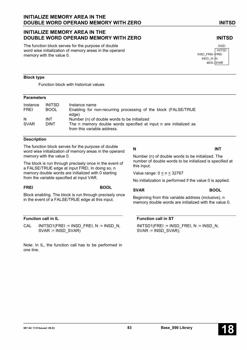
INITIALIZE MEMORY AREA IN THEDOUBLE WORD OPERAND MEMORY WITH ZERO INITSD
907 AC 1131/Issued: 09.03 83 Base_S90 Library 18
INITIALIZE MEMORY AREA IN THEDOUBLE WORD OPERAND MEMORY WITH ZERO INITSDThe function block serves for the purpose of doubleword wise initialization of memory areas in the operandmemory with the value 0.
Block typeFunction block with historical values
ParametersInstance INITSD Instance nameFREI BOOL Enabling for non-recurring processing of the block (FALSE/TRUE
edge)N INT Number (n) of double words to be initializedSVAR DINT The n memory double words specified at input n are initialized as
from this variable address.
DescriptionThe function block serves for the purpose of doubleword wise initialization of memory areas in the operandmemory with the value 0.
The block is run through precisely once in the event ofa FALSE/TRUE edge at input FREI. In doing so, nmemory double words are initialized with 0 startingfrom the variable specified at input VAR.
FREI BOOLBlock enabling. The block is run through precisely oncein the event of a FALSE/TRUE edge at this input.
N INTNumber (n) of double words to be initialized. Thenumber of double words to be initialized is specified atthis input.
Value range: 0 < n < 32767
No initialization is performed if the value 0 is applied.
SVAR BOOLBeginning from this variable address (inclusive), nmemory double words are initialized with the value 0.
Function call in ILCAL INITSD1(FREI := INSD_FREI, N := INSD_N,
SVAR := INSD_SVAR)
Note: In IL, the function call has to be performed inone line.
Function call in STINITSD1(FREI := INSD_FREI, N := INSD_N,SVAR := INSD_SVAR);
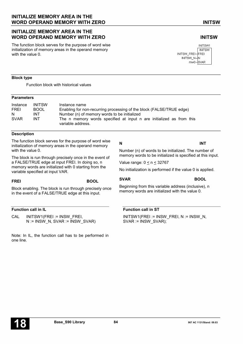
INITIALIZE MEMORY AREA IN THEWORD OPERAND MEMORY WITH ZERO INITSW
Base_S90 Library 84 907 AC 1131/Stand: 09.0318
INITIALIZE MEMORY AREA IN THEWORD OPERAND MEMORY WITH ZERO INITSWThe function block serves for the purpose of word wiseinitialization of memory areas in the operand memorywith the value 0.
Block typeFunction block with historical values
ParametersInstance INITSW Instance nameFREI BOOL Enabling for non-recurring processing of the block (FALSE/TRUE edge)N INT Number (n) of memory words to be initializedSVAR INT The n memory words specified at input n are initialized as from this
variable address.
DescriptionThe function block serves for the purpose of word wiseinitialization of memory areas in the operand memorywith the value 0.
The block is run through precisely once in the event ofa FALSE/TRUE edge at input FREI. In doing so, nmemory words are initialized with 0 starting from thevariable specified at input VAR.
FREI BOOLBlock enabling. The block is run through precisely oncein the event of a FALSE/TRUE edge at this input.
N INTNumber (n) of words to be initialized. The number ofmemory words to be initialized is specified at this input.
Value range: 0 < n < 32767
No initialization is performed if the value 0 is applied.
SVAR BOOLBeginning from this variable address (inclusive), nmemory words are initialized with the value 0.
Function call in ILCAL INITSW1(FREI := INSW_FREI,
N := INSW_N, SVAR := INSW_SVAR)
Note: In IL, the function call has to be performed inone line.
Function call in STINITSW1(FREI := INSW_FREI, N := INSW_N,SVAR := INSW_SVAR);

INITIALIZE VARIABLES, BINARY INITVB(16..32)
907 AC 1131/Issued: 09.03 85 Base_S90 Library 18
INITIALIZE VARIABLES, BINARY INITVB(16..32)The block serves to initialize BINARY variables.
The INITVB number indicates the maximum number ofvariables to be initialized. The following blocks areavailable:
INITVB16 Variables initialization (binary) for amax. of 16 variables
INITVB32 Variables initialization (binary) for amax. of 32 variables
Block typeFunction block with historical values
ParametersInstance INITVB(16..32) Instance nameFREI BOOL Enabling for non-recurring processing of the block
(FALSE/TRUE edge)N INT Number of variables to be initializedW0..Wn-1 BOOL Initialization value for the subsequent variable;VR0..VRn-1 DWORD Variable address to be initialized
DescriptionThe block serves to initialize BINARY variables withnumeric values.
The initialization values are specified at the block inputsW0..Wn-1. The block is run through precisely once inthe event of a FALSE/TRUE edge at input FREI.
FREI BOOLThe block is run through precisely once in the event ofa FALSE/TRUE edge at input FREI.
n INTThe number (n) of variables to be initialized is specifiedat input n.
W0..Wn-1 BOOLThe initialization value for the subsequent variable isspecified at input W0.
The inputs W0 and VR0 can be duplicated in pairs.
The following allocation applies:
Value 0 → Variable 0 : :Value n-1 → Variable n-1
VR0..VRn-1 DWORDThe first variable to be initialized is specified at inputVR0. The block ADR provides the corresponding binaryflag address.
The inputs VR0 and W0 can be duplicated in pairs.

INITIALIZE VARIABLES, BINARY INITVB(16..32)
Base_S90 Library 86 907 AC 1131/Stand: 09.0318
Function call in ILLD INITVB_V0ADRST INITVB161.V0LD INITVB_V1ADRST INITVB161.V1LD INITVB_V2ADRST INITVB161.V2CAL INITVB161(FREI := INITVB_FREI, N := 3,
W0 := INITVB_W0, W1 := INITVB_W1,W2 := INITVB_W2)
Note: In IL, the function call has to be performed inone line.
Function call in STINITVB161.V0 := ADR(INITVB_V0);INITVB161.V1 := ADR(INITVB_V1);INITVB161.V2 := ADR(INITVB_V2);INITVB161(FREI := INITVB_FREI, N := 3,W0 := INITVB_W0, W1 := INITVB_W1,W2 := INITVB_W2);

INITIALIZE VARIABLES, WORD INITVW(16..32)
907 AC 1131/Issued: 09.03 87 Base_S90 Library 18
INITIALIZE VARIABLES, WORD INITVW(16..32)The block serves to initialize word variables withnumeric values.
The INITVW number indicates the maximum number ofvariables to be initialized. The following blocks areavailable:
INITVW16 Variables initialization (word) for a max.of 16 variables
INITVW32 Variables initialization (word) for a max.32 of variables
Block typeFunction block with historical values
ParametersInstance INITVW(16..32) Instance nameFREI BOOL Enabling for non-recurring processing of the block (FALSE/TRUE
edge)N INT Number of variables to be initializedW0..Wn-1 INT Initialization value for the subsequent variable;VR0..VRn-1 INT Variable to be initialized
DescriptionThe block serves to initialize word variables withnumeric values.
The initialization values are specified at the block inputsW0..Wn-1. The block is run through precisely once inthe event of a FALSE/TRUE edge at input FREI.
FREI BOOLThe block is run through precisely once in the event ofa FALSE/TRUE edge at input FREI.
n INTThe number (n) of variables to be initialized is specifiedat input n.
W0..Wn-1 INTThe initialization value for the subsequent variable isspecified at input W0.
The inputs W0 and VR0 can be duplicated in pairs.
The following allocation applies:
Value 0 → Variable 0 : :Value n-1→ Variable n-1
VR0..VRn-1 INTThe first variable to be initialized is specified at inputVR0.
The inputs VR0 and W0 can be duplicated in pairs.

INITIALIZE VARIABLES, WORD INITVW(16..32)
Base_S90 Library 88 907 AC 1131/Stand: 09.0318
Function call in ILCAL INITVW161(FREI := INITVW_FREI, N := 3,
W0 := INITVW_W0, W1 := INITVW_W0,W2 := INITVW_W0,V0 := INITVW_V0,V1 := INITVW_V0, V2 := INITVW_V0)
Note: In IL, the function call has to be performed inone line.
Function call in STINITVW161(FREI := INITVW_FREI, N := 3,W0 := INITVW_W0, W1 := INITVW_W0,W2 := INITVW_W0,V0 := INITVW_V0,V1 := INITVW_V0, V2 := INITVW_V0);

INTEGRATOR (EXTENDED) INTK
907 AC 1131/Issued: 09.03 89 Base_S90 Library 18
INTEGRATOR (EXTENDED) INTKThis block generates the integral of the controlledvariable x multiplied by the proportional coefficient KP.
Block typeFunction block with historical values
ParametersInstance INTK Instance nameX INT Controlled variableT1_TZ INT Integration time scaled to the cycle timeRES INT Reset output Y to 0STOP BOOL Integrator stopSET BOOL Set output to INIT valueINIT INT Initial valueKP INT Proportional coefficient, output as a percentage valueOG INT High limit for the manipulated variable YUG INT Low limit for the manipulated variable YOG_MELD BOOL Output Y has reached top limitUG_MELD BOOL Output Y has reached low limitY INT Manipulated variable
DescriptionThis block generates the integral of the controlledvariable x multiplied by the proportional coefficient KP.The integrator output Y can be manipulated as follows:
• It can be set to the value 0 by a 1 signal at input RES(reset).
• It can be latched to the current value by a TRUEsignal at input STOP.
• It can be set to the initial at input INIT by a TRUEsignal at input SET.
• It can be limited to a maximum value specified atinput OG (high limit).
• It can be limited to a minimum value specified at inputUG (low limit).
The inputs and outputs can neither be duplicated nornegated/inverted.

INTEGRATOR (EXTENDED) INTK
Base_S90 Library 90 907 AC 1131/Stand: 09.0318
Transfer function:
KPF(s) = –––––
s * T
X INTThe operand for the controlled variable is specified atinput X.
T1_TZ INTThe integration time is specified at input T1_TZ. In thiscase it must be scaled to the cycle time. During thetime T1 the output Y of the integrator changes by thevalue KP * X.
Value range: 0 < T1_TZ < 328
• If values are specified which are beyond theadmissible value range the PLC generally uses thevalue 328.
• A large integration time (T1) can be achieved bychoosing a large cycle time T, too. If the block is usedwithin a run number block, the cycle time of the runnumber block is valid for block INTK and not the cycletime (KD 0,0) of the PLC program.
INTEGRATOR (EXTENDED) INTK
907 AC 1131/Issued: 09.03 91 Base_S90 Library 18
RES BOOL *)The output Y can be reset to the value 0 with the inputRES. Integration then again begins as from the value 0.
STOP BOOL *)Integration can be stopped with input STOP.
STOP = FALSE→ integration is not stopped
STOP = TRUE→ integration is stopped, i.e. output Y no longerchanges.
SET BOOL *)With the input SET, the manipulated value Y can be setto the initial value specified at input INIT. Integrationthen again begins as from the initial value.
S = FALSE → no settingS = TRUE → output Y is set to the specified initial
value
*) Priority sequence for the inputs STOP, SET andRES:
RES highest prioritySTOPSET lowest priority
INIT INTThe initial value to which output Y is to be set isspecified at input INIT if required.
KP INTThe proportional coefficient is specified at input KP. Itserves to weight the controlled variable at input X.Weighting is achieved by multiplying the controlledvariable by the proportional coefficient. Theproportional coefficient is specified as a percentage.
Example:1 = 1 percent
55 = 55 percent100 = 100 percent
1000 = 1000 percent-100 = -100 percent
• 1 percent means that the block multiplies the value atinput X by the factor 0.01.
• 100 percent means that the block multiplies the valueat input X by the factor 1.
• 1000 percent means that the block multiplies thevalue at input X by the factor 10.
OG INTThe manipulated variable Y can be limited to a valuerange. The high limit for the manipulated variable Y isspecified at input OG.
UG INTThe manipulated variable Y can be limited to a valuerange. The low limit for the manipulated variable Y isspecified at input UG.
OG_MELD BOOLWhether the value at output Y has reached thespecified top limit is signalized at output OG_MELD.Integration is stopped automatically when the limit isreached.
OG_MELD = FALSE →Y has not reached the limit
OG_MELD = TRUE
→ Y has reached the limit
UG_MELD BOOLWhether the value at output Y has reached thespecified low limit is signalized at output UG_MELD.Integration is stopped automatically when the limit isreached.
UG_MELD = FALSE→ Y has not reached the limit
UG_MELD = TRUE
→ Y has reached the limit
Y INTThe manipulated variable (output value of theintegrator) is output through the output Y.

INTEGRATOR (EXTENDED) INTK
Base_S90 Library 92 907 AC 1131/Stand: 09.0318
Function call in ILCAL INTK1(X := INTK_X, T1_TZ := INTK_T1TZ,
RES := INTK_RES, STOP := INTK_STOP,SET := INTK_SET, INIT := INTK_INIT,KP := INTK_KP, OG := INTK_OG,UG := INTK_UG)
LD INTK1.OG_MELDST INTK_MOGLD INTK1.UG_MELDST INTK_MUGLD INTK1.YST INTK_Y
Note: In IL, the function call has to be performed inone line.
Function call in STINTK1(X := INTK_X, T1_TZ := INTK_T1TZ,RES := INTK_RES, STOP := INTK_STOP,SET := INTK_SET, INIT := INTK_INIT,KP := INTK_KP, OG := INTK_OG, UG := INTK_UG);INTK_MOG:=INTK1.OG_MELD;INTK_MUG:=INTK1.UG_MELD;INTK_Y:=INTK1.Y;

ILLUMINATION PUSHBUTTON CONTROL LDT
907 AC 1131/Issued: 09.03 93 Base_S90 Library 18
ILLUMINATION PUSHBUTTON CONTROL LDTThis function block changes the polarity at output Awith every FALSE/TRUE edge at input E (like animpulse relay).
Block typeFunction block with historical values
ParametersInstance LDT Instance nameEIN BOOL Dynamic input for activating output AAUS BOOL Dynamic input for deactivating output AE BOOL Dynamic input for activating and deactivating output ARES BOOL Static input for deactivating output AA BOOL OutputEINI BOOL Pulse for the duration of one PLC program cycle when activating output AAUSI BOOL Pulse for the duration of one PLC program cycle when deactivating output A
Description see next page

ILLUMINATION PUSHBUTTON CONTROL LDT
Base_S90 Library 94 907 AC 1131/Stand: 09.0318
This function block changes the polarity at output Awith every FALSE/TRUE edge at input E (like animpulse relay). However, this only applies if input RESis inactive. Output A can be influenced additionally withthe inputs EIN, AUS and RES.
All inputs except RES are edge-controlled, i. e. theyreact only to a FALSE/TRUE edge. The input RES isactive for as long as a static 1 signal is present at it.Brief pulses are available at output EINI and AUSIwhen a status change of output A occurs.
EIN BOOLOutput A is set with every FALSE/TRUE edge at inputEIN. However, this only applies when the inputs AUS,E and R are inactive. Therefore, the input EIN has thelowest priority of all inputs.
AUS BOOLOutput A is reset with every FALSE/TRUE edge atinput AUS. Therefore, input AUS has a higher prioritythan input EIN, but a lower priority than the inputs Eand RES.
E BOOLWith every FALSE/TRUE edge at input E, the blockchanges the priority at output A. However, this onlyapplies if input R is inactive. Therefore, input E has ahigher priority than the inputs EIN and AUS, but a lowerpriority than input RES.
RES BOOLOutput A is reset when a static TRUE signal is presentat input RES.
The RES input has a higher priority than the inputs Eand EIN. A priority conflict with the input AUS is notpossible because both inputs have the same effect onthe outputs.
A BOOLOutput A is changed corresponding to the definition ofthe inputs.
EINI BOOLA pulse is generated at output EINI with everyFALSE/TRUE edge at output A. The length of thispulse is 1 program cycle.
AUSI BOOLA pulse is generated at output AUSI with everyTRUE/FALSE edge at output A. The length of thispulse is 1 program cycle.
Function call in ILCAL LDT1(EIN := LDT_EIN, AUS := LDT_AUS,
E := LDT_E, RES := LDT_RES)
LD LDT1.EINIST LDT_EINILD LDT1.AUSIST LDT_AUSILD LDT1.AST LDT_A
Note: In IL, the function call has to be performed inone line.
Function call in STLDT1(EIN := LDT_EIN, AUS := LDT_AUS,E := LDT_E, RES := LDT_RES);LDT_EINI:=LDT1.EINI;LDT_AUSI:=LDT1.AUSI;LDT_A:=LDT1.A;
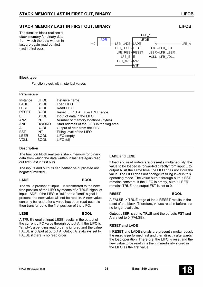
STACK MEMORY LAST IN FIRST OUT, BINARY LIFOB
907 AC 1131/Issued: 09.03 95 Base_S90 Library 18
STACK MEMORY LAST IN FIRST OUT, BINARY LIFOBThe function block realizes astack memory for binary datafrom which the data written inlast are again read out first(last in/first out).
Block typeFunction block with historical values
ParametersInstance LIFOB Instance nameLADE BOOL Load LIFOLESE BOOL Read LIFORESET BOOL Reset LIFO, FALSE→TRUE edgeE BOOL Input of data in the LIFOANZ INT Number of memory locations (bytes)ANF DWORD Start address of the LIFO in the flag areaA BOOL Output of data from the LIFOFST INT Filling level of the LIFOLEER BOOL LIFO emptyVOLL BOOL LIFO full
DescriptionThe function block realizes a stack memory for binarydata from which the data written in last are again readout first (last in/first out).
The inputs and outputs can neither be duplicated nornegated/inverted.
LADE BOOLThe value present at input E is transferred to the nextfree position of the LIFO by means of a TRUE signal atinput LADE. If the LIFO is "full" and a "load" signal ispresent, the new value will not be read in. A new valuecan only be read after a value has been read out. It isthen transferred to the first position of the LIFO.
LESE BOOLA TRUE signal at input LESE results in the output ofthe current LIFO value through output A. If the LIFO is"empty", a pending read order is ignored and the valueFALSE is output at output A. Output A is always set toFALSE if there is no read order.
LADE and LESEIf load and read orders are present simultaneously, thevalue to be loaded is forwarded directly from input E tooutput A. At the same time, the LIFO does not store thevalue. The LIFO does not change its filling level in thisoperating mode. The value output through output FSTremains constant. If the LIFO is empty, output LEERremains TRUE and output FST is set to 0.
RESET BOOLA FALSE -> TRUE edge at input RESET results in thereset of the block. Therefore, values read in before areno longer available.
Output LEER is set to TRUE and the outputs FST andA are set to 0 (FALSE).
RESET and LADEIf RESET and LADE signals are present simultaneouslythe reset is performed first and then directly afterwardsthe load operation. Therefore, the LIFO is reset and thenew value to be read in is then immediately stored inthe LIFO as the first value.
STACK MEMORY LAST IN FIRST OUT, BINARY LIFOB
Base_S90 Library 96 907 AC 1131/Stand: 09.0318
RESET and LADE and LESEThe value at input E is forwarded directly to output A.Output LEER is set permanently to TRUE and outputFST is set permanently to 0.
E BOOLThe value to be transferred into the LIFO is specified atinput E.
ANZ INTThe number of required memory locations (bytes) ofthe LIFO is specified at input ANZ. The number ofmemory locations corresponds to the number of binaryvalues to be stored.
ANF DWORDThe LIFO memory start address is specified at inputANF. The block ADR provides the corresponding binaryflag address. The LIFO begins with the specified flag.
A BOOLWhen the LIFO is read, the current value is available atoutput A. If no read order is available, the value FALSEis output.
FST INTOutput FST indicates the current filling level of the LIFOat any time. The filling level is the number of binaryvalues stored in the LIFO.
LEER BOOLThe output LEER indicates whether or not the LIFO isempty.
LEER = FALSE → LIFO is not emptyLEER = TRUE → LIFO is empty
VOLL BOOLThe output VOLL indicates whether or not the LIFO isfull.
VOLL = FALSE → LIFO is not fullVOLL = TRUE → LIFO is full
No further values can be read in if the LIFO is full. Anew value can only be read in after a value has beenread out. The new value is positioned to the beginningof the LIFO.
Function call in ILLD LIFO_ANFADRST LIFOB1.ANF
CAL LIFOB1(LADE := LIFO_LADE,LESE := LIFO_LESE, RESET := LIFO_RES,E := LIFO_E, ANZ := LIFO_ANZ)
LD LIFOB1.FSTST LIFO_FSTLD LIFOB1.LEERST LIFO_LEERLD LIFOB1.VOLLST LIFO_VOLLLD LIFOB1.AST LIFO_A
Note: In IL, the function call has to be performed inone line.
Function call in STLIFOB1.ANF := ADR(LIFO_ANF);LIFOB1(LADE := LIFO_LADE, LESE := LIFO_LESE,RESET := LIFO_RES, E := LIFO_E,ANZ := LIFO_ANZ);LIFO_FST:=LIFOB1.FST;LIFO_LEER:=LIFOB1.LEER;LIFO_VOLL:=LIFOB1.VOLL;LIFO_A:=LIFOB1.A;

STACK MEMORY LAST IN FIRST OUT, WORD LIFOW
907 AC 1131/Issued: 09.03 97 Base_S90 Library 18
STACK MEMORY LAST IN FIRST OUT, WORD LIFOWThe function block realizes a stack memory for worddata from which the data written in last are again readout first (last in/first out).
Block typeFunction block with historical values
ParametersInstance LIFOW Instance nameLADE BOOL Load LIFOLESE BOOL Read LIFORESET BOOL Reset LIFO, FALSE→TRUE edgeE INT Input of data in the LIFOANZ INT Number of memory locations (bytes)ANF INT Start address of the LIFO in the flag areaA INT Output of data from the LIFOFST INT Filling level of the LIFOLEER BOOL LIFO emptyVOLL BOOL LIFO full
DescriptionThe function block realizes a stack memory for worddata from which the data written in last are againread out first (last in/first out).
The inputs and outputs can neither be duplicated nornegated/inverted.
LADE BOOLThe value present at input E is transferred to the nextfree position of the LIFO by means of a TRUE signalat input LADE. If the LIFO is "full" and a "load" signalis present, the new value will not be read in. A newvalue can only be read if a value has been read outfirst. It is then transferred to the first position of theLIFO.
LESE BOOLA TRUE signal at input LESE results in the output ofthe current LIFO value through output A. If the LIFOis "empty", a pending read order is ignored and thevalue 0 is output at output A. Output A is always setto 0 if there is no read order.
LADE und LESEIf load and read orders are present simultaneously,the value to be loaded is forwarded directly from inputE to output A. At the same time, the LIFO does notstore the value. The LIFO does not change its fillinglevel in this operating mode. The value outputthrough output FST remains constant. If the LIFO isempty, output LEER remains TRUE and output FSTis set to 0.
RESET BOOLA FALSE -> TRUE edge at input RESET results inthe reset of the block. Therefore, values read inbefore are no longer available.
Output LEER is set to TRUE and the outputs FSTand A are set to 0.
RESET and LADEIf RESET and LADE signals are presentsimultaneously the reset is performed first and thendirectly afterwards the load operation. Therefore, theLIFO is reset and the new value to be read in is thenimmediately stored in the LIFO as the first value.

STACK MEMORY LAST IN FIRST OUT, WORD LIFOW
Base_S90 Library 98 907 AC 1131/Stand: 09.0318
RESET and LADE and LESEThe value at input E is forwarded directly to output A.Output LEER is set permanently to TRUE and outputFST is set permanently to 0.
E INTThe value to be transferred into the LIFO is specifiedat input E.
ANZ INTThe number of required memory locations (words) ofthe LIFO is specified at input ANZ. The number ofmemory locations corresponds to the number ofbinary values to be stored.
ANF INTThe LIFO memory start address is specified as abinary flag at input ANF. The LIFO begins with thespecified flag.
A INTWhen the LIFO is read, the current value is availableat output A. If no read order is available, the value 0is output.
FST INTOutput FST indicates the current filling level of theLIFO at any time. The filling level is the number ofbinary values stored in the LIFO.
LEER BOOLThe output LEER indicates whether or not the LIFO isempty.
LEER = FALSE → LIFO is not emptyLEER = TRUE → LIFO is empty
VOLL BOOLThe output VOLL indicates whether or not the LIFO isfull.
VOLL = FALSE → LIFO is not fullVOLL = TRUE → LIFO is full
No further values can be read in if the LIFO is full. Anew value can only be read in after a value has beenread out. The new value is positioned to thebeginning of the LIFO.
Function call in ILLD LIFO_ANFADRST LIFOW1.ANF
CAL LIFOW1(LADE := LIFO_LADE,LESE := LIFO_LESE, RESET := LIFO_RES,E := LIFO_E, ANZ := LIFO_ANZ)
LD LIFOW1.FSTST LIFO_FSTLD LIFOW1.LEERST LIFO_LEERLD LIFOW1.VOLLST LIFO_VOLLLD LIFOW1.AST LIFO_A
Note: In IL, the function call has to be performed inone line.
Function call in ST
LIFOW1.ANF := ADR(LIFO_ANF);LIFOW1(LADE := LIFO_LADE,LESE := LIFO_LESE, RESET := LIFO_RES,E := LIFO_E, ANZ := LIFO_ANZ);LIFO_FST:=LIFOW1.FST;LIFO_LEER:=LIFOW1.LEER;LIFO_VOLL:=LIFOW1.VOLL;LIFO_A:=LIFOW1.A;

LISTENZUORDNER LIZU(8..256)
907 AC 1131/Issued: 09.03 99 Base_S90 Library 18
LIST ALLOCATOR LIZU(8..256)The function block has a list of word data at its inputs.With a list pointer, it selects a value out of this list andapplies it at its output.
The LIZU number indicates the maximum number ofword data. The following list allocators are available:
LIZU8 List allocator for max. 8 word dataLIZU16 List allocator for max. 16 word dataLIZU32 List allocator for max. 32 word dataLIZU64 List allocator for max. 64 word dataLIZU256 List allocator for max. 256 word data
Block typeFunction block without historical values
ParametersInstance LIZU(8..256) Instance nameZEIG INT Pointer to the list of word dataN INT Number of word data in the listE0..En-1 INT List of word dataA_E BOOL 0 < ZEIG < n, i.e. pointer in the valid rangeA INT Selected word value
DescriptionThe function block has a list of word data at its inputs.With a list pointer, it selects a value out of this list andapplies it at its output.
The inputs and outputs cannot be inverted. The inputE0 can be duplicated.
ZEIG INTThe pointer to the word value to be selected from thelist is specified at input ZEIG.
The following allocation applies:
ZEIG = 0 → Word value at E0ZEIG = 1 → Word value at E1. : :ZEIG = n-1 → Word value at En-1
The value at input ZEIG is monitored for validity. Theresult of this range check is signalized at output A_E.
Allowed range:
0 < ZEIG < n-1
With n: Number of the inputs E0..En-1.
No allocation to output A takes place if the value atinput ZEIG is outside the allowed range.
n INTThe number of the word values planned at the inputsE0..En-1 is specified at input n.
E0-…-En-1 INTThe word values out of which one is selected with thevalue at input ZEIG and assigned to output A arespecified at the inputs E0 ... En-1.
A_E BOOLOutput A_E indicates whether the value of the listpointer (input ZEIG) is within the allowed range.
Allowed range:
0 < ZEIG < n-1
With n: Number of the inputs E0..En-1.
The following applies:
ZEIG in the allowed range → A_E = TRUEZEIG in the forbidden range → A_E = FALSE

LISTENZUORDNER LIZU(8..256)
Base_S90 Library 100 907 AC 1131/Stand: 09.0318
If the list pointer has a forbidden value, no allocationof a value to output A takes place because no wordvalue can be selected. In this case, output A is notupdated.
A INTThe value of the selected word value is assigned tothe operand at output A.
Function call in ILCAL LIZU81(ZEIG := LIZU_ZEIG, n := 3,
E0 := LIZU_E0, E1 := LIZU_E1,E2 := LIZU_E2)
LD LIZU81.AST LIZU_ALD LIZU81.A_EST LIZU_AE
Note: In IL, the function call has to be performed inone line.
Function call in STLIZU81(ZEIG := LIZU_ZEIG,
n := 3,E0 := LIZU_E0,E1 := LIZU_E1,E2 := LIZU_E2) ;
LIZU_A := LIZU81.ALIZU_AE := LIZU81.AE

LAUFZAHLBLOCK LZB
907 AC 1131/Issued: 09.03 101 Base_S90 Library 18
RUN NUMBER BLOCK LZBThe block controls the processing of a program part.This program part is called run number block andbegins with the function block LZB and ends with theappropriate target label specified at the block outputMRK. This program part is processed as followsdepending on the value of the operand at input E1.
Block typeFunction block with historical values
ParametersInstance LZB Instance nameE1 INT Run numberMRK SPRUNG Target label
DescriptionThe block controls processing of a program part. Thisprogram part is called run number block and beginswith the function block LZB and ends with theappropriate target label specified at the block outputMRK. This program part is processed as followsdepending on the value of the operand at input E1:
E1 = 0: Program part is not processedE1 = 1: Program part is processed during every
cycleE1 = 2: Program part is processed during every
second cycle: :E1 = n: Program part is processed during every
nth cycle
E1 INTThis program part is processed as follows dependingon the value of the operand at input E1:
E1 = 0: Program part is not processedE1 = 1: Program part is processed during every
cycleE1 = 2: Program part is processed during every
second cycle: :E1 = n: Program part is processed during every
nth cycle
MRK BOOLAt this output, a jump instruction with correspondingjump destination must be specified. Output MRK onlysignalizes, whether the subsequent program part isprocessed or not.
The following applies:
MRK = FALSE: Processing of program partMRK = TRUE: No processing of program part
Function call in ILCAL LZB1(E1 := LZB_E1)LD LZB1.MRKJMPC MARKE
Note: In IL, the function call has to be performed inone line.
Function call in STLZB1(E1 := LZB_E1);
IF (LZB1.MRK)THEN .....;
END_IF

MAJORITY MAJ
Base_S90 Library 102 907 AC 1131/Stand: 09.0318
MAJORITY MAJThis block realizes a majority element.
Block typeFunction
ParametersE1 BOOL Operand 1E2 BOOL Operand 2E3 BOOL Operand 3A BOOL Result
DescriptionThis block realizes a majority element.
If at least 2 of the 3 binary operands at the inputs E1,E2 and E3 have the state TRUE, then the state TRUEis assigned to the binary operand at output A. The stateFALSE is assigned if this is not the case.
The inputs and the output cannot be duplicated.
Function call in ILLD MAJ_E1MAJ MAJ_E2,MAJ_E3ST MAJ_A
Function call in STMAJ_A := MAJ(MAJ_E1,MAJ_E2,MAJ_E3);
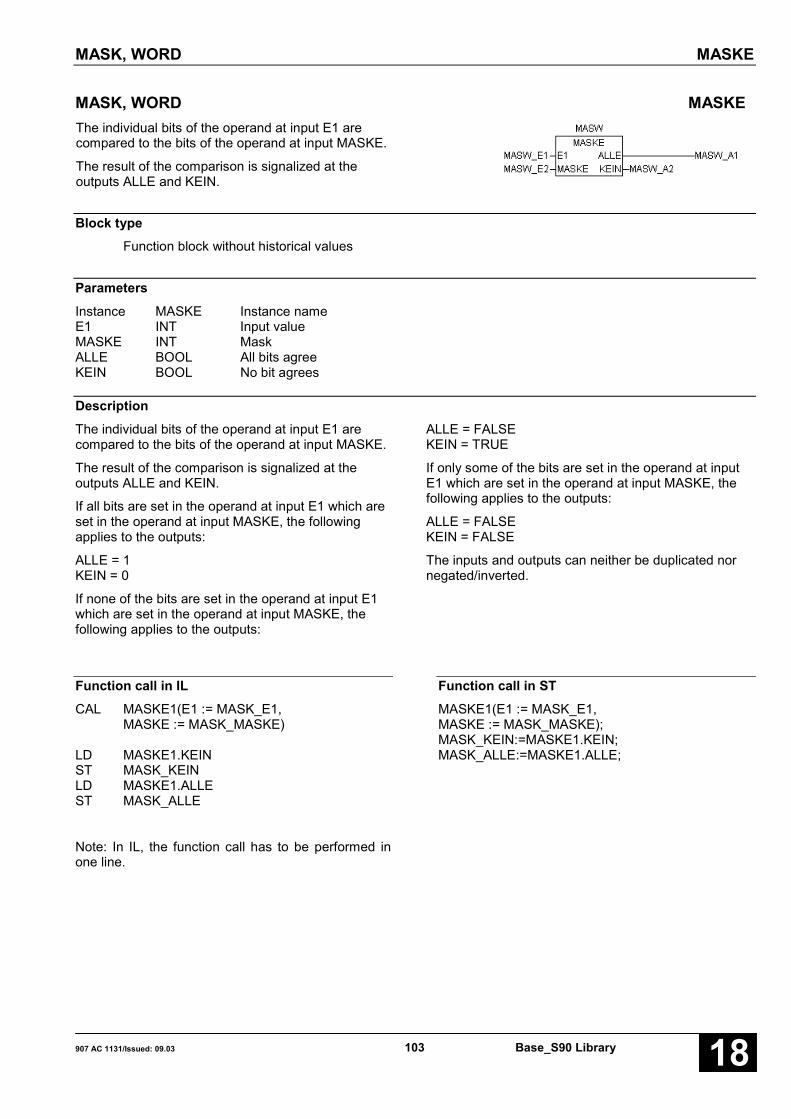
MASK, WORD MASKE
907 AC 1131/Issued: 09.03 103 Base_S90 Library 18
MASK, WORD MASKEThe individual bits of the operand at input E1 arecompared to the bits of the operand at input MASKE.
The result of the comparison is signalized at theoutputs ALLE and KEIN.
Block typeFunction block without historical values
ParametersInstance MASKE Instance nameE1 INT Input valueMASKE INT MaskALLE BOOL All bits agreeKEIN BOOL No bit agrees
DescriptionThe individual bits of the operand at input E1 arecompared to the bits of the operand at input MASKE.
The result of the comparison is signalized at theoutputs ALLE and KEIN.
If all bits are set in the operand at input E1 which areset in the operand at input MASKE, the followingapplies to the outputs:
ALLE = 1KEIN = 0
If none of the bits are set in the operand at input E1which are set in the operand at input MASKE, thefollowing applies to the outputs:
ALLE = FALSEKEIN = TRUE
If only some of the bits are set in the operand at inputE1 which are set in the operand at input MASKE, thefollowing applies to the outputs:
ALLE = FALSEKEIN = FALSE
The inputs and outputs can neither be duplicated nornegated/inverted.
Function call in ILCAL MASKE1(E1 := MASK_E1,
MASKE := MASK_MASKE)
LD MASKE1.KEINST MASK_KEINLD MASKE1.ALLEST MASK_ALLE
Note: In IL, the function call has to be performed inone line.
Function call in STMASKE1(E1 := MASK_E1,MASKE := MASK_MASKE);MASK_KEIN:=MASKE1.KEIN;MASK_ALLE:=MASKE1.ALLE;

MASK, DOUBLE WORD MASKED
Base_S90 Library 104 907 AC 1131/Stand: 09.0318
MASK, DOUBLE WORD MASKEDThe individual bits of the operand at input E1 arecompared to the bits of the operand at input MASKE.
The result of the comparison is signalized at theoutputs ALLE and KEIN.
Block typeFunction block without historical values
ParametersInstance MASKED Instance nameE1 DINT Input valueMASKE DINT MaskALLE BOOL All bits agreeKEIN BOOL No bit agrees
DescriptionThe individual bits of the operand at input E1 arecompared to the bits of the operand at input MASKE.
The result of the comparison is signalized at theoutputs ALLE and KEIN.
If all bits are set in the operand at input E1 which areset in the operand at input MASKE, the followingapplies to the outputs:
ALLE = TRUEKEIN = FALSE
If none of the bits are set in the operand at input E1which are set in the operand at input MASKE, thefollowing applies to the outputs:
ALLE = FALSEKEIN = TRUE
If only some of the bits are set in the operand at inputE1 which are set in the operand at input MASKE, thefollowing applies to the outputs:
ALLE = FALSEKEIN = FALSE
The inputs and outputs can neither be duplicated nornegated/inverted.
Function call in ILCAL MASKED1(E1 := MASKD_E1,
MASKED := MASKD_MASKE)
LD MASKED1.KEINST MASKD_KEINLD MASKED1.ALLEST MASKD_ALLE
Note: In IL, the function call has to be performed inone line.
Function call in STMASKED1(E1 := MASKD_E1,MASKED := MASKD_MASKE);MASKD_KEIN:=MASKED1.KEIN;MASKD_ALLE:=MASKED1.ALLE;

MAXIMUM VALUE GENERATOR ASA FUNCTION OF TIME, WORD MAZ
907 AC 1131/Issued: 09.03 105 Base_S90 Library 18
MAXIMUM VALUE GENERATOR ASA FUNCTION OF TIME, WORD MAZThis function block determines the maximum value of asignal up to the current point of time by evaluating thetime behaviour of the signal.
Block typeFunction block with historical values
ParametersInstance MAZ Instance nameE1 INT Input value whose time maximum has to be determinedSET BOOL Set inputINIT INT Initial valueMAZ INT Maximum value
DescriptionThis function block determines the maximum value of asignal up to the current point of time by evaluating thetime behaviour of the signal.
The value of the operand at input E1 is compared tothe previously occurred maximum value. If the inputvalue E1 is higher than the previously occurredmaximum, the input value is the new maximum valueand is assigned to the operand at output MAZ.
If the input value E1 is less than the previouslyoccurred maximum value, the previous maximum valueis assigned to the output.
Output MAZ is set to the value of the operand at inputINIT (initial value) with the FALSE → TRUE edge atbinary input SET.
The following applies:
E1 < MAZ → MAZ = MAZE1 > MAZ → MAZ = E1SET = FALSE→TRUE edge → MAZ = INIT
The inputs and the output can neither be duplicated nornegated/inverted.
Function call in ILCAL MAZ1(E1 := MAZ_E1, SET := MAZ_SET,
INIT := MAZ_INIT)
LD MAZ1.MAZST MAZ_MAZ
Note: In IL, the function call has to be performed inone line.
Function call in STMAZ1(E1 := MAZ_E1, SET := MAZ_SET,INIT := MAZ_INIT);MAZ_MAZ:=MAZ1.MAZ;
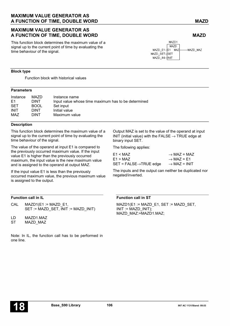
MAXIMUM VALUE GENERATOR ASA FUNCTION OF TIME, DOUBLE WORD MAZD
Base_S90 Library 106 907 AC 1131/Stand: 09.0318
MAXIMUM VALUE GENERATOR ASA FUNCTION OF TIME, DOUBLE WORD MAZDThis function block determines the maximum value of asignal up to the current point of time by evaluating thetime behaviour of the signal.
Block typeFunction block with historical values
ParametersInstance MAZD Instance nameE1 DINT Input value whose time maximum has to be determinedSET BOOL Set inputINIT DINT Initial valueMAZ DINT Maximum value
DescriptionThis function block determines the maximum value of asignal up to the current point of time by evaluating thetime behaviour of the signal.
The value of the operand at input E1 is compared tothe previously occurred maximum value. If the inputvalue E1 is higher than the previously occurredmaximum, the input value is the new maximum valueand is assigned to the operand at output MAZ.
If the input value E1 is less than the previouslyoccurred maximum value, the previous maximum valueis assigned to the output.
Output MAZ is set to the value of the operand at inputINIT (initial value) with the FALSE → TRUE edge atbinary input SET.
The following applies:
E1 < MAZ → MAZ = MAZE1 > MAZ → MAZ = E1SET = FALSE→TRUE edge → MAZ = INIT
The inputs and the output can neither be duplicated nornegated/inverted.
Function call in ILCAL MAZD1(E1 := MAZD_E1,
SET := MAZD_SET, INIT := MAZD_INIT)
LD MAZD1.MAZST MAZD_MAZ
Note: In IL, the function call has to be performed inone line.
Function call in STMAZD1(E1 := MAZD_E1, SET := MAZD_SET,INIT := MAZD_INIT);MAZD_MAZ:=MAZD1.MAZ;
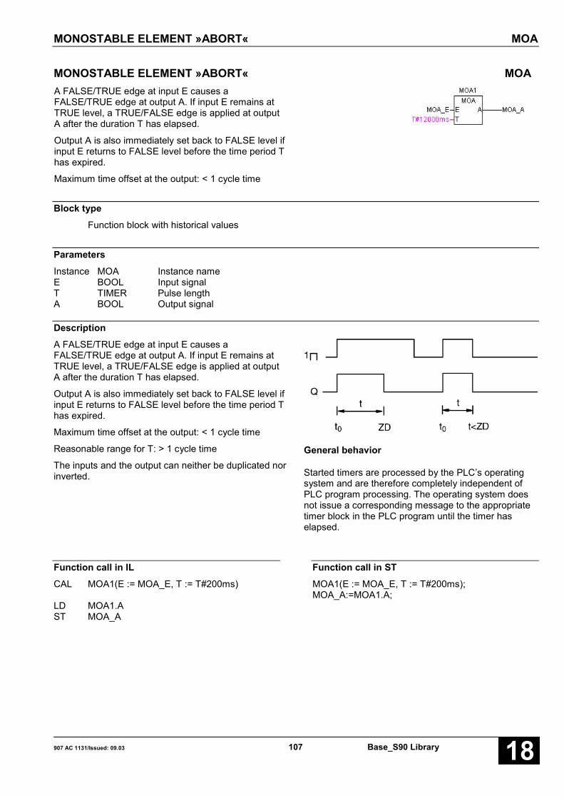
MONOSTABLE ELEMENT »ABORT« MOA
907 AC 1131/Issued: 09.03 107 Base_S90 Library 18
MONOSTABLE ELEMENT »ABORT« MOAA FALSE/TRUE edge at input E causes aFALSE/TRUE edge at output A. If input E remains atTRUE level, a TRUE/FALSE edge is applied at outputA after the duration T has elapsed.
Output A is also immediately set back to FALSE level ifinput E returns to FALSE level before the time period Thas expired.
Maximum time offset at the output: < 1 cycle time
Block typeFunction block with historical values
ParametersInstance MOA Instance nameE BOOL Input signalT TIMER Pulse lengthA BOOL Output signal
DescriptionA FALSE/TRUE edge at input E causes aFALSE/TRUE edge at output A. If input E remains atTRUE level, a TRUE/FALSE edge is applied at outputA after the duration T has elapsed.
Output A is also immediately set back to FALSE level ifinput E returns to FALSE level before the time period Thas expired.
Maximum time offset at the output: < 1 cycle time
Reasonable range for T: > 1 cycle time
The inputs and the output can neither be duplicated norinverted.
General behavior
Started timers are processed by the PLC’s operatingsystem and are therefore completely independent ofPLC program processing. The operating system doesnot issue a corresponding message to the appropriatetimer block in the PLC program until the timer haselapsed.
Function call in ILCAL MOA1(E := MOA_E, T := T#200ms)
LD MOA1.AST MOA_A
Function call in STMOA1(E := MOA_E, T := T#200ms);MOA_A:=MOA1.A;

MONOSTABLE ELEMENT »CONSTANT« MOK
Base_S90 Library 108 907 AC 1131/Stand: 09.0318
MONOSTABLE ELEMENT »CONSTANT« MOKA FALSE/TRUE edge at input E causes aFALSE/TRUE edge at output A. If input E remains atTRUE level, a TRUE/FALSE edge is applied at outputA after the duration T has elapsed.
A possible second FALSE/TRUE edge of input E whichoccurs before the time period T has elapsed is ignored.
Maximum time offset at the output: < 1 cycle time
Block typeFunction block with historical values
ParametersInstance MOK Instance nameE BOOL Input signalT TIMER Pulse lengthA BOOL Output signal
DescriptionA FALSE/TRUE edge at input E causes aFALSE/TRUE edge at output A. If input E remains atTRUE level, a TRUE/FALSE edge is applied at outputA after the duration T has elapsed.
A possible second FALSE/TRUE edge of input E whichoccurs before the time period T has elapsed is ignored.
Maximum time offset at the output: < 1 cycle time
Reasonable range for T: > 1 cycle time
The inputs and the output can neither be duplicated norinverted.
General behaviorStarted timers are processed by the PLC’s operatingsystem and are therefore completely independent ofPLC program processing. The operating system doesnot issue a corresponding message to the appropriatetimer block in the PLC program until the timer haselapsed.
Function call in ILCAL MOK1(E := MOK_E, T := T#200ms)
LD MOK1.AST MOK_A
Function call in STMOK1(E := MOK_E, T := T#200ms);MOK_A:=MOK1.A;

MULTIPLICATION BY 2 TO THE POWER OF N, WORD MUL2N
907 AC 1131/Issued: 09.03 109 Base_S90 Library 18
MULTIPLICATION BY 2 TO THE POWER OF N, WORD MUL2NThe value of the operand at input E1 is shifted bitwiseN times.
If the value at input N is positive, the value is shifted tothe left. Each shift by 1 bit position corresponds to amultiplication of the current value by 2.
If the value at input N is negative, the value is shifted tothe right. Each shift by 1 bit position corresponds to adivision of the current value by 2.
The result is assigned to the operand at output A1.
Block typeFunction
ParametersE1 INT Input operandN INT QuantityA1 INT Result
DescriptionThe value of the operand at input E1 is shifted bitwiseN times.
If the value at input N is positive, the value is shifted tothe left. Each shift by 1 bit position corresponds to amultiplication of the current value by 2.
If the value at input N is negative, the value is shifted tothe right. Each shift by 1 bit position corresponds to adivision of the current value by 2.
The result is assigned to the operand at output A1.
The inputs and the output can neither be duplicated nornegated.
Reasonable range for N: -14 < N < +14
If N = 0, the value at input E1 is passed directly tooutput A1.
Sign of the value at input E1:The sign of value E1 is not influenced by the shiftoperation. I.e. the sign of the output value is alwaysidentical with the sign of the input value.
Shift to the left (Multiplication):When the value at the input is shifted to the left, thereleased bit 0 is filled with 0. The sign bit (bit 15) is notchanged because a limiting to the limit of the numberrange is performed before.
Limiting the value at output A1 when shifting to the left:
• The following applies to positive values at input E1:If bit 14 has a »1« and if shift operations still have to
be carried out on the basis of the value at input N,these are no longer executed. Instead, the output isset to the limit of the positive number range. I.e. thelimit has been reached in any case at the latest after14 shifts.
Limit value: Output A1 = +32767 (7FFFH).
• The following applies to negative values at input E1:If bit 14 has a »0« and if shift operations still have tobe carried out on the basis of the value at input N,these are no longer executed. Instead, the output isset to the limit of the negative number range. I.e. thelimit has been reached in any case at the latest after14 shifts.
Limit value: Output A1 = -32767 (8001H).
Shift to the right (Division):When shifting to the right, every bit moves to the rightby one position. At the same time, the sign bit (bit 15)always retains its value. The released bit (bit 14) isfilled in each case with the value of the sign bit.
Limiting the value at the output when shifting to theright:

MULTIPLICATION BY 2 TO THE POWER OF N, WORD MUL2N
Base_S90 Library 110 907 AC 1131/Stand: 09.0318
• The following applies to positive values at input E1:If now only bit 0 has a »1« and shift operations stillhave to be carried out because of the value at inputN, the output will be set to the value 0. I.e. value 0has been reached in any case at the latest after 14shifts.
Output A1 = 0.
• The following applies to negative values at input E1:If bit 0 ... bit 15 has a »1« as the result of the shift, thelimit value (-1) has been reached. Further shifts haveno effect. I.e. the value -1 has been reached at thelatest after 15 shifts.
Output A1 = -1 (FFFFH).
The inputs and the output can neither be duplicated nornegated.
Examples:1. Input value E1 = 5498 (157AH)
Exponent N = 2 � 2 * Left shift
2. Input value E1 = 32612 (7F64H)Exponent N = -3 � 3 * Right shift
3. Input value E1 = -32612 (8008H)Exponent N = -3 � 3 * Right shift
Function call in ILLD MUL2N_E1MUL2N MUL2N_NST MUL2N_A
Function call in STMUL2N_A:=MUL2N(MUL2N_E1, MUL2N_N);

MULTIPLICATION BY 2 TO THE POWER OF N, DOUBLE WORD MUL2ND
907 AC 1131/Issued: 09.03 111 Base_S90 Library 18
MULTIPLICATION BY 2 TO THE POWER OF N, DOUBLE WORD MUL2NDThe value of the operand at input E1 is shifted bitwiseN times.
If the value at input N is positive, the value is shifted tothe left. Each shift by 1 bit position corresponds to amultiplication of the current value by 2.
If the value at input N is negative, the value is shifted tothe right. Each shift by 1 bit position corresponds to adivision of the current value by 2.
The result is assigned to the operand at output A1.
Block typeFunction
ParametersE1 DINT Input operandN INT QuantityA1 DINT Result
DescriptionThe value of the operand at input E1 is shifted bit-wiseN times.
If the value at input N is positive, the value is shifted tothe left. Each shift by 1 bit position corresponds to amultiplication of the current value by 2.
If the value at input N is negative, the value is shifted tothe right. Each shift by 1 bit position corresponds to adivision of the current value by 2.
The result is assigned to the operand at output A1.
The inputs and the output can neither be duplicated nornegated.
Reasonable range for N: -30 < N < +30
If N = 0, the value at input E1 is passed directly tooutput A1.
Sign of the value at input E1:The sign of value E1 is not influenced by the shiftoperation. I.e. the sign of the output value is alwaysidentical with the sign of the input value.
Shift to the left (Multiplication):When the value at the input is shifted to the left, thereleased bit 0 is filled with 0. The sign bit (bit 31) is notchanged because a limiting to the limit of the numberrange is performed before.
Limiting the value at output A1 when shifting to the left:
• The following applies to positive values at input E1:If bit 30 has a »1« and if shift operations still have tobe carried out on the basis of the value at input N,these are no longer executed. Instead, the output isset to the limit of the positive number range. I.e. thelimit has been reached in any case at the latest after30 shifts.
Limit value:Output A1 = +2147483647 (7FFFFFFFH).
• The following applies to negative values at input E1:If bit 30 has a »0« and if shift operations still have tobe carried out on the basis of the value at input N,these are no longer executed. Instead, the output isset to the limit of the negative number range. I.e. thelimit has been reached in any case at the latest after30 shifts.
Limit value:Output A1 = -2147483647 (80000001H).
Shift to the right (Division):When shifting to the right, every bit moves to the rightby one position. At the same time, the sign bit (bit 31)always retains its value. The released bit (bit 30) isfilled in each case with the value of the sign bit.

MULTIPLICATION BY 2 TO THE POWER OF N, DOUBLE WORD MUL2ND
Base_S90 Library 112 907 AC 1131/Stand: 09.0318
Limiting the value at the output when shifting to theright:
• The following applies to positive values at input E1:If now only bit 0 has a »1« and shift operations stillhave to be carried out because of the value at inputN, the output will be set to the value 0. I.e. value 0has been reached in any case at the latest after 30shifts.
Output A1 = 0.
• The following applies to negative values at input E1:If bit 0 ... bit 31 has a »1« as the result of the shift, thelimit value (-1) has been reached. Further shifts haveno effect. I.e. the value -1 has been reached at thelatest after 31 shifts.
Output A1 = -1 (FFFFFFFFH).
The inputs and the output can neither be duplicated nornegated.
Examples:1. Input value E1 = 58350926 (37A5D4EH)
Exponent N = 4 � 4 * Left shift
2. Input value E1 = 326786382 (137A5D4EH)Exponent N = -4 � 4 * Right shift
3. Input value E1 = -326786382 (EC85A2B2H)Exponent N = -4 � 4 * Right shift
Function call in ILLD MUL2ND_E1MUL2ND MUL2ND_NST MUL2ND_A
Function call in STMUL2ND_A:=MUL2ND(MUL2ND_E1, MUL2ND_N);
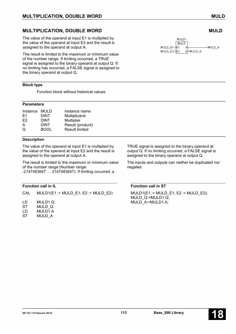
MULTIPLICATION, DOUBLE WORD MULD
907 AC 1131/Issued: 09.03 113 Base_S90 Library 18
MULTIPLICATION, DOUBLE WORD MULDThe value of the operand at input E1 is multiplied bythe value of the operand at input E2 and the result isassigned to the operand at output A.
The result is limited to the maximum or minimum valueof the number range. If limiting occurred, a TRUEsignal is assigned to the binary operand at output Q. Ifno limiting has occurred, a FALSE signal is assigned tothe binary operand at output Q.
Block typeFunction block without historical values
ParametersInstance MULD Instance nameE1 DINT MultiplicandE2 DINT MultiplierA DINT Result (product)Q BOOL Result limited
DescriptionThe value of the operand at input E1 is multiplied bythe value of the operand at input E2 and the result isassigned to the operand at output A.
The result is limited to the maximum or minimum valueof the number range (Number range:-2147483647 … 2147483647). If limiting occurred, a
TRUE signal is assigned to the binary operand atoutput Q. If no limiting occurred, a FALSE signal isassigned to the binary operand at output Q.
The inputs and outputs can neither be duplicated nornegated.
Function call in ILCAL MULD1(E1 := MULD_E1, E2 := MULD_E2)
LD MULD1.QST MULD_QLD MULD1.AST MULD_A
Function call in STMULD1(E1 := MULD_E1, E2 := MULD_E2);MULD_Q:=MULD1.Q;MULD_A:=MULD1.A;

MULTIPLICATION WITH DIVISION MULDI
Base_S90 Library 114 907 AC 1131/Stand: 09.0318
MULTIPLICATION WITH DIVISION MULDIThe operand value at input E1 is multiplied by theoperand value at input E2, the intermediate result isdivided by the operand value at E3 and then the resultis assigned to output A.
The result is limited to the maximum or minimum valueof the number range.
Block typeFunction
ParametersE1 INT MultiplicandE2 INT MultiplierE3 INT DivisorA INT Result
DescriptionThe operand value at input E1 is multiplied by theoperand value at input E2, the intermediate result isdivided by the operand value at E3 and then the resultis assigned to output A.
Internal, the block performs the multiplication anddivision with the accuracy of a double word (32 bit).Only when assigning the result to output A, the limitingto the accuracy of a word (16 bit) is carried out. If the
remainder of the division is > 0,5, the result is roundedup. If a numerical overflow occurs during the division(e.g. division by zero), the correct signed limit of thenumber range is applied at output A.
The result is limited to the maximum value 32767 andthe minimum value -32767.
The inputs and the output can neither be duplicated nornegated.
Function call in ILLD MULDI_E1MULDI MULDI_E2,MULDI_E3ST MULDI_A
Function call in STMULDI_A := MULDI(MULDI_E1, MULDI_E2,MULDI_E3);

MULTIPLICATION, WORD MULW
907 AC 1131/Issued: 09.03 115 Base_S90 Library 18
MULTIPLICATION, WORD MULWThe values of the operands at the inputs of the functionare multiplied and the result is assigned to the operandat the output.
The result is limited to the maximum or minimum valueof the number range.
Block typeFunction
ParametersE1 INT MultiplicandE2 INT MultiplierA INT Result (product)
DescriptionThe values of the operands at the inputs of the functionare multiplied and the result is assigned to the operandat the output.
The result is limited to the maximum value 32767 andthe minimum value -32767.
The inputs and the output can neither be duplicated nornegated.
Function call in ILLD MULW_E1MULW MULW_E2,MULW_E3ST MULW_A
Function call in STMULW_A := MULW(MULW_E1, MULW_E2);
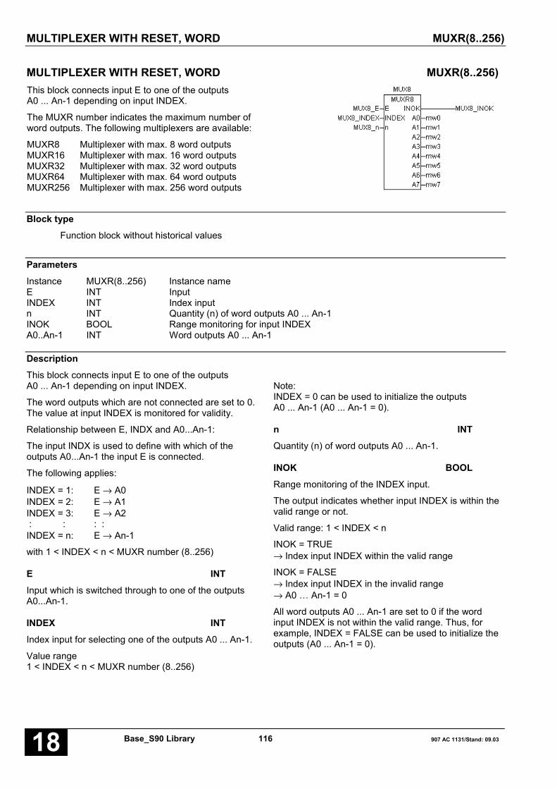
MULTIPLEXER WITH RESET, WORD MUXR(8..256)
Base_S90 Library 116 907 AC 1131/Stand: 09.0318
MULTIPLEXER WITH RESET, WORD MUXR(8..256)This block connects input E to one of the outputsA0 ... An-1 depending on input INDEX.
The MUXR number indicates the maximum number ofword outputs. The following multiplexers are available:
MUXR8 Multiplexer with max. 8 word outputsMUXR16 Multiplexer with max. 16 word outputsMUXR32 Multiplexer with max. 32 word outputsMUXR64 Multiplexer with max. 64 word outputsMUXR256 Multiplexer with max. 256 word outputs
Block typeFunction block without historical values
ParametersInstance MUXR(8..256) Instance nameE INT InputINDEX INT Index inputn INT Quantity (n) of word outputs A0 ... An-1INOK BOOL Range monitoring for input INDEXA0..An-1 INT Word outputs A0 ... An-1
DescriptionThis block connects input E to one of the outputsA0 ... An-1 depending on input INDEX.
The word outputs which are not connected are set to 0.The value at input INDEX is monitored for validity.
Relationship between E, INDX and A0...An-1:
The input INDX is used to define with which of theoutputs A0...An-1 the input E is connected.
The following applies:
INDEX = 1: E → A0INDEX = 2: E → A1INDEX = 3: E → A2 : : : :INDEX = n: E → An-1
with 1 < INDEX < n < MUXR number (8..256)
E INTInput which is switched through to one of the outputsA0...An-1.
INDEX INTIndex input for selecting one of the outputs A0 ... An-1.
Value range1 < INDEX < n < MUXR number (8..256)
Note:INDEX = 0 can be used to initialize the outputsA0 ... An-1 (A0 ... An-1 = 0).
n INTQuantity (n) of word outputs A0 ... An-1.
INOK BOOLRange monitoring of the INDEX input.
The output indicates whether input INDEX is within thevalid range or not.
Valid range: 1 < INDEX < n
INOK = TRUE→ Index input INDEX within the valid range
INOK = FALSE→ Index input INDEX in the invalid range→ A0 … An-1 = 0
All word outputs A0 ... An-1 are set to 0 if the wordinput INDEX is not within the valid range. Thus, forexample, INDEX = FALSE can be used to initialize theoutputs (A0 ... An-1 = 0).

MULTIPLEXER WITH RESET, WORD MUXR(8..256)
907 AC 1131/Issued: 09.03 117 Base_S90 Library 18
A0..An-1 INT
The output A0 can be duplicated (A0 ... An-1).The input E is assigned to one of the n outputsA0 ... An-1.
Function call in ILCAL MUXR81(E := MUXR_E,
INDEX := MUXR_IND, n := 3)
LD MUXR81.A0ST MUXR_A0LD MUXR81.A1ST MUXR_A1LD MUXR81.A2ST MUXR_A2LD MUXR81.INOKST MUXR_INOK
Note: In IL, the function call has to be performed inone line.
Function call in STMUXR81(E := MUXR_E, INDEX := MUXR_IND,n := 3);MUXR_A0:=MUXR81.A0;MUXR_A1:=MUXR81.A1;MUXR_A2:=MUXR81.A2;MUXR_INOK:=MUXR81.INOK;
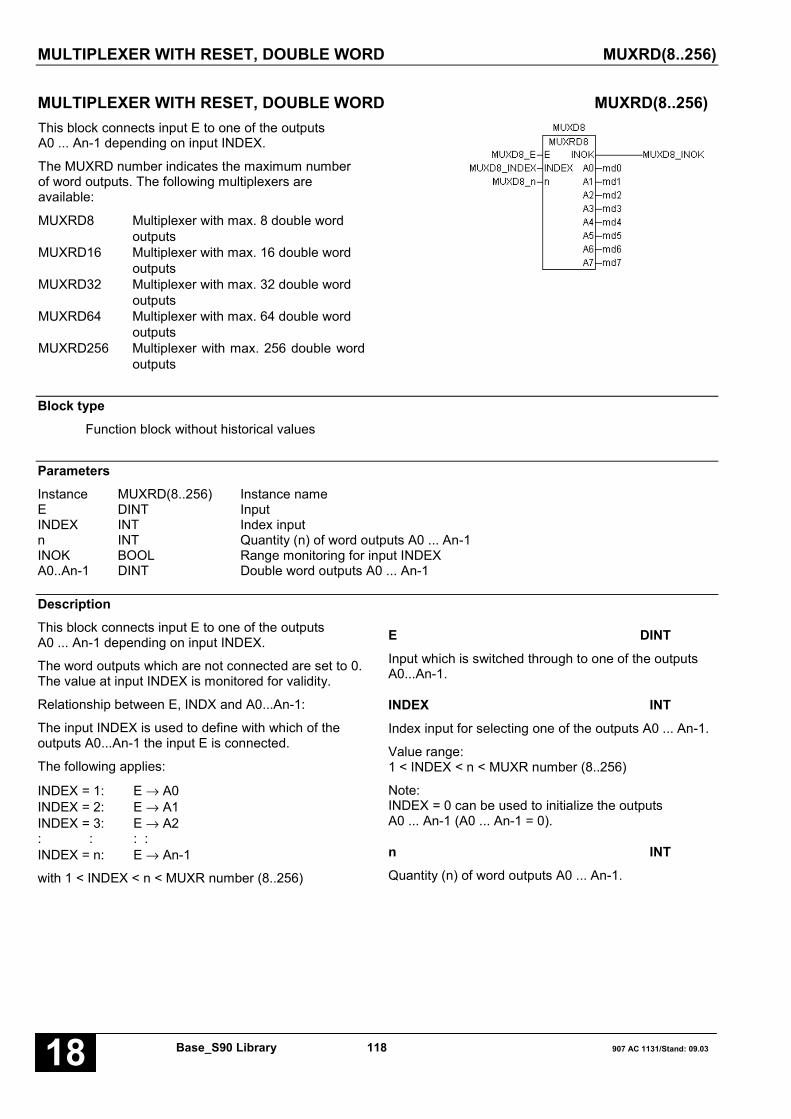
MULTIPLEXER WITH RESET, DOUBLE WORD MUXRD(8..256)
Base_S90 Library 118 907 AC 1131/Stand: 09.0318
MULTIPLEXER WITH RESET, DOUBLE WORD MUXRD(8..256)This block connects input E to one of the outputsA0 ... An-1 depending on input INDEX.
The MUXRD number indicates the maximum numberof word outputs. The following multiplexers areavailable:
MUXRD8 Multiplexer with max. 8 double wordoutputs
MUXRD16 Multiplexer with max. 16 double wordoutputs
MUXRD32 Multiplexer with max. 32 double wordoutputs
MUXRD64 Multiplexer with max. 64 double wordoutputs
MUXRD256 Multiplexer with max. 256 double wordoutputs
Block typeFunction block without historical values
ParametersInstance MUXRD(8..256) Instance nameE DINT InputINDEX INT Index inputn INT Quantity (n) of word outputs A0 ... An-1INOK BOOL Range monitoring for input INDEXA0..An-1 DINT Double word outputs A0 ... An-1
DescriptionThis block connects input E to one of the outputsA0 ... An-1 depending on input INDEX.
The word outputs which are not connected are set to 0.The value at input INDEX is monitored for validity.
Relationship between E, INDX and A0...An-1:
The input INDEX is used to define with which of theoutputs A0...An-1 the input E is connected.
The following applies:
INDEX = 1: E → A0INDEX = 2: E → A1INDEX = 3: E → A2: : : :INDEX = n: E → An-1
with 1 < INDEX < n < MUXR number (8..256)
E DINTInput which is switched through to one of the outputsA0...An-1.
INDEX INTIndex input for selecting one of the outputs A0 ... An-1.
Value range:1 < INDEX < n < MUXR number (8..256)
Note:INDEX = 0 can be used to initialize the outputsA0 ... An-1 (A0 ... An-1 = 0).
n INTQuantity (n) of word outputs A0 ... An-1.
MULTIPLEXER WITH RESET, WORD MUXR(8..256)
907 AC 1131/Issued: 09.03 119 Base_S90 Library 18
INOK BOOLRange monitoring of the INDEX input.
The output indicates whether input INDEX is within thevalid range or not.
Valid range: 1 < INDEX < n
INOK = TRUE → Index input INDEX within the valid range
INOK = FALSE → Index input INDEX in the invalid range
→ A0 … An-1 = 0
All word outputs A0 ... An-1 are set to 0 if the wordinput INDEX is not within the valid range. Thus, forexample, INDEX = 0 can be used to initialize theoutputs (A0 ... An-1 = 0).
A0..An-1 DINT
The output A0 can be duplicated (A0 ... An-1). Theinput E is assigned to one of the n outputs A0 ... An-1.
Function call in ILCAL MUXRD81(E := MUXRD_E,
INDEX := MUXRD_IND, n := 3)
LD MUXRD81.A0ST MUXRD_A0LD MUXRD81.A1ST MUXRD_A1LD MUXRD81.A2ST MUXRD_A2LD MUXRD81.INOKST MUXRD_INOK
Note: In IL, the function call has to be performed inone line.
Function call in STMUXRD81(E := MUXRD_E, INDEX := MUXRD_IND,n := 3);MUXRD_A0:=MUXRD81.A0;MUXRD_A1:=MUXRD81.A1;MUXRD_A2:=MUXRD81.A2;MUXRD_INOK:=MUXRD81.INOK;
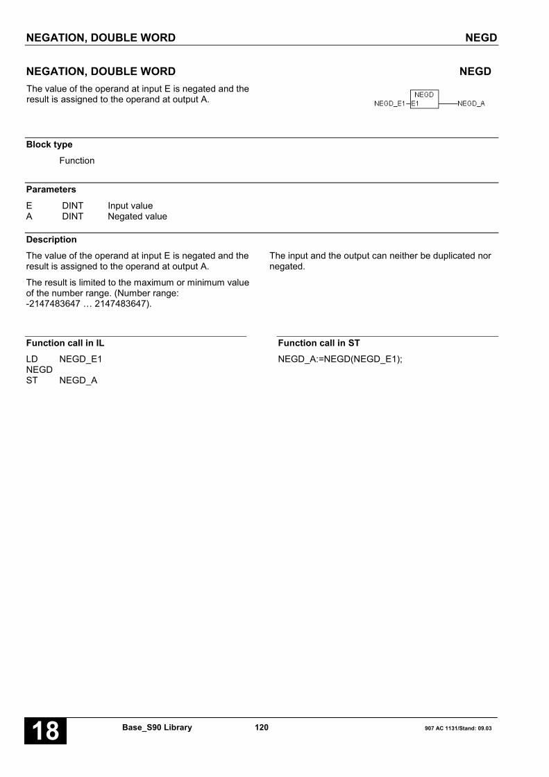
NEGATION, DOUBLE WORD NEGD
Base_S90 Library 120 907 AC 1131/Stand: 09.0318
NEGATION, DOUBLE WORD NEGDThe value of the operand at input E is negated and theresult is assigned to the operand at output A.
Block typeFunction
ParametersE DINT Input valueA DINT Negated value
DescriptionThe value of the operand at input E is negated and theresult is assigned to the operand at output A.
The result is limited to the maximum or minimum valueof the number range. (Number range:-2147483647 … 2147483647).
The input and the output can neither be duplicated nornegated.
Function call in ILLD NEGD_E1NEGDST NEGD_A
Function call in STNEGD_A:=NEGD(NEGD_E1);

NEGATION, WORD NEGW
907 AC 1131/Issued: 09.03 121 Base_S90 Library 18
NEGATION, WORD NEGWThe value of the operand at input E is negated and theresult is assigned to the operand at output A.
Block typeFunction
ParametersE INT Input valueA INT Negated value
DescriptionThe value of the operand at input E is negated and theresult is assigned to the operand at output A.
The result is limited to the maximum or minimum valueof the number range. (Number range:-2147483647 … 2147483647).
The input and the output can neither be duplicated nornegated.
Function call in ILLD NEGW_E1NEGWST NEGW_A
Function call in STNEGW_A:=NEGW(NEGW_E1);
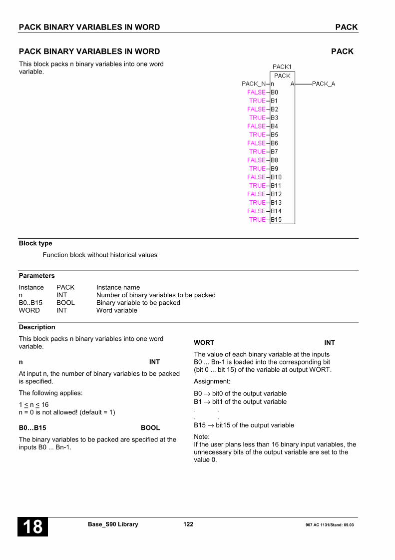
PACK BINARY VARIABLES IN WORD PACK
Base_S90 Library 122 907 AC 1131/Stand: 09.0318
PACK BINARY VARIABLES IN WORD PACKThis block packs n binary variables into one wordvariable.
Block typeFunction block without historical values
ParametersInstance PACK Instance namen INT Number of binary variables to be packedB0..B15 BOOL Binary variable to be packedWORD INT Word variable
DescriptionThis block packs n binary variables into one wordvariable.
n INTAt input n, the number of binary variables to be packedis specified.
The following applies:
1 < n < 16n = 0 is not allowed! (default = 1)
B0…B15 BOOLThe binary variables to be packed are specified at theinputs B0 ... Bn-1.
WORT INTThe value of each binary variable at the inputsB0 ... Bn-1 is loaded into the corresponding bit(bit 0 ... bit 15) of the variable at output WORT.
Assignment:
B0 → bit0 of the output variableB1 → bit1 of the output variable. .. .B15 → bit15 of the output variable
Note:If the user plans less than 16 binary input variables, theunnecessary bits of the output variable are set to thevalue 0.

PACK BINARY VARIABLES IN WORD PACK
907 AC 1131/Issued: 09.03 123 Base_S90 Library 18
Function call in ILCAL PACK1(n := 3, B0 := PACK_B0,
B1 := PACK_B1, B2 := PACK_B2)
LD PACK1.AST PACK_A
Note: In IL, the function call has to be performed inone line.
Function call in STPACK1(n := 3, B0 := PACK_B0, B1 := PACK_B1,B2 := PACK_B2);PACK_A:=PACK1.A;

PACK BINARY VARIABLES IN DOUBLE WORD PACKD
Base_S90 Library 124 907 AC 1131/Stand: 09.0318
PACK BINARY VARIABLES IN DOUBLE WORD PACKDThis block packs n binary variables into one doubleword variable.
Block typeFunction block without historical values
ParametersInstance PACKD Instance namen INT Number of binary variables to be packedB0..B15 BOOL Binary variable to be packedA DINT Double word variable
DescriptionThis block packs n binary variables into one doubleword variable.
n INTAt input n, the number of binary variables to bepacked is specified.
The following applies:
1 < n < 32n = 0 is not allowed! (default = 1)
B0…B31 BOOLThe binary variables to be packed are specified at theinputs B0 ... Bn-1.
A DINTThe value of each binary variable at the inputsB0 ... Bn-1 is loaded into the corresponding bit(bit 0 ... bit 13) of the variable at output A.
Assignment:
B0 → bit0 of the output variableB1 → bit1 of the output variable. .. .B31 → bit31 of the output variable
Note:If the user plans less than 31 binary input variables,the unnecessary bits of the output variable are set tothe value 0.

PACK BINARY VARIABLES IN DOUBLE WORD PACKD
907 AC 1131/Issued: 09.03 125 Base_S90 Library 18
Function call in ILCAL PACKD1(n := 3, B0 := PACKD_B0,
B1 := PACKD_B1, B2 := PACKD_B2)
LD PACKD1.AST PACKD_A
Note: In IL, the function call has to be performed inone line.
Function call in STPACKD1(n := 3, B0 := PACKD_B0,B1 := PACKD_B1, B2 := PACKD_B2);PACKD_A:=PACKD1.A;
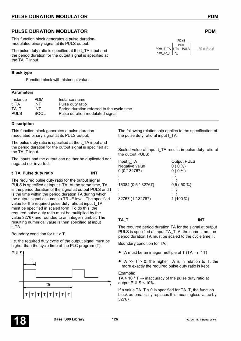
PULSE DURATION MODULATOR PDM
Base_S90 Library 126 907 AC 1131/Stand: 09.0318
PULSE DURATION MODULATOR PDMThis function block generates a pulse duration-modulated binary signal at its PULS output.
The pulse duty ratio is specified at the t_TA input andthe period duration for the output signal is specified atthe TA_T input.
Block typeFunction block with historical values
ParametersInstance PDM Instance namet_TA INT Pulse duty ratioTA_T INT Period duration referred to the cycle timePULS BOOL Pulse duration modulated signal
DescriptionThis function block generates a pulse duration-modulated binary signal at its PULS output.
The pulse duty ratio is specified at the t_TA input andthe period duration for the output signal is specified atthe TA_T input.
The inputs and the output can neither be duplicated nornegated nor inverted.
t_TA Pulse duty ratio INTThe required pulse duty ratio for the output signalPULS is specified at input t_TA. At the same time, TAis the period duration of the signal at output PULS and tis the time within the period duration TA during whichthe output signal assumes a TRUE level. The specifiedvalue for the required pulse duty ratio at input t_TAmust be specified in scaled form. To do this, therequired pulse duty ratio must be multiplied by thevalue 32767 and rounded to an integer number. Theresulting numerical value is then specified at inputt_TA.
Boundary condition for t: t > T
I.e. the required duty cycle of the output signal must behigher than the cycle time of the PLC program (T).
The following relationship applies to the specification ofthe pulse duty ratio at input t_TA:
Scaled value at input t_TA results in pulse duty ratio atthe output PULS:
Input t_TA Output PULSNegative value 0 ( 0 %)0 (0 * 32767) 0 ( 0 %): : :: : :16384 (0,5 * 32767) 0,5 ( 50 %): : :: : :32767 (1 * 32767) 1 (100 %)
TA_T INTThe required period duration TA for the signal at outputPULS is specified at input TA_T. At the same time, theperiod duration TA must be scaled to the cycle time T.
Boundary condition for TA:
• TA must be an integer multiple of T (TA = n * T)
• TA >> T > 0; the higher TA is in relation to T, themore exactly the required pulse duty ratio is kept
Example:TA > 10 * T → inaccuracy of the pulse duty ratio atoutput PULS < 10%.
If a value TA_T < 0 is specified for TA_T, the functionblock automatically replaces this meaningless value by32767.

PULSE DURATION MODULATOR PDM
907 AC 1131/Issued: 09.03 127 Base_S90 Library 18
PULS BOOLThe pulse duration modulated signal is available atoutput PULS.
Combination of the PDM block with a controller
If the PDM function block is connected to the output ofa controller in order to realize a »switching« controller,the following boundary conditions apply:
– Period duration TA of the PDM = sampling time ofthe controller.
– Period of the pulse signal must be synchronous withthe period of the controller sampling time.
These boundary conditions are fulfilled by planning thecontroller in the same PLC program as the PDM, butwithin one run number block. By means of the runnumber block, the sampling time of the controller isprolonged by an integer multiple of the cycle time.Therefore, the controller is processed less frequentlywithin the run number block than the PDM outside ofthe run number block.
ExampleRequired:
– Pulse duty ratio: t_TA = 0,25 (25 %)– Period duration: TA = 800 ms (only an integer
multiple of the PLC cycle time is possible)– Cycle time: T = 100 ms
Block parameters to be specified:
– Value at input t_TA: 8192 (0,25 * 32767)– Value at input TA_T: 8 (800 ms/100 ms)
Function call in ILCAL PDM1(t_TA := PDM_TTA,
TA_T := PDM_TAT)
LD PDM1.PULSST PDM_PULS
Note: In IL, the function call has to be performed inone line.
Function call in STPDM1(t_TA := PDM_TTA, TA_T := PDM_TAT);PDM_PULS:=PDM1.PULS;
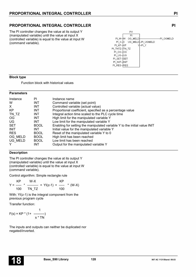
PROPORTIONAL INTEGRAL CONTROLLER PI
Base_S90 Library 128 907 AC 1131/Stand: 09.0318
PROPORTIONAL INTEGRAL CONTROLLER PIThe PI controller changes the value at its output Y(manipulated variable) until the value at input X(controlled variable) is equal to the value at input W(command variable).
Block typeFunction block with historical values
ParametersInstance PI Instance nameW INT Command variable (set point)X INT Controlled variable (actual value)KP INT Proportional coefficient, specified as a percentage valueTN_TZ INT Integral action time scaled to the PLC cycle timeOG INT High limit for the manipulated variable YUG INT Low limit for the manipulated variable YSET BOOL Enabling for setting the manipulated variable Y to the initial value INITINIT INT Initial value for the manipulated variable YRES BOOL Reset of the manipulated variable Y to 0OG_MELD BOOL High limit has been reachedUG_MELD BOOL Low limit has been reachedY INT Output for the manipulated variable Y
DescriptionThe PI controller changes the value at its output Y(manipulated variable) until the value at input X(controlled variable) is equal to the value at input W(command variable).
Control algorithm: Simple rectangle rule
KP W-X KPY = ––– * –––––– + YI(z-1) + ––– * (W-X)
100 TN_TZ 100
With: YI(z-1) is the integral component from theprevious program cycle
Transfer function:
1F(s) = KP * (1+ ––––––)
s * TN
The inputs and outputs can neither be duplicated nornegated/inverted.

PROPORTIONAL INTEGRAL CONTROLLER PI
907 AC 1131/Issued: 09.03 129 Base_S90 Library 18
PI controller: Surge-free transition from the specified
value to control operation PI controller: Surging transition from the specifiedinitial value to control operation

PROPORTIONAL INTEGRAL CONTROLLER PI
Base_S90 Library 130 907 AC 1131/Stand: 09.0318
W INTThe command variable (set point) is specified at inputW.
X INTThe controlled variable (actual value) is specified atinput X.
KP INTThe proportional coefficient is specified at input KP.This value is specified as a percentage value. Positiveor negative values are possible.
Example:1 = 1 percent
55 = 55 percent100 = 100 percent
1000 = 1000 percent-500 = -500 percent
• 1 percent means that the block multiplies the systemdeviation by the factor 0.01 (see also controlalgorithm)
• 100 percent means that the block multiplies thesystem deviation by the factor 1 (see also controlalgorithm)
• 1000 percent means that the block multiplies thesystem deviation by the factor 10 (see also controlalgorithm)
Generally, proportional coefficients of more than 1000percent are not meaningful in control systems.
TN_TZ INTThe integral action time TN is scaled to the PLC cycletime TZ and is specified at input TN_TZ.
Value range: 0 < TN_TZ < 328
• If values are specified which are not within theadmissible value range the PLC generally uses thevalue 328.
• A large integral action time TN can be achieved bychoosing a large cycle time T, too. If the block is usedwithin a run number block, the cycle time of the runnumber block is valid for block INTK and not the cycletime (KD 0,0) of the PLC program.
Limiting the manipulated variable Y
OG, UG INTThe controller output Y (manipulated variable) can belimited
– to a maximum value by specifying a limit at input OG(high limit)
– to a minimum value by specifying a limit at input UG(low limit)
The high and low limits also apply to the controller’sinternal I component. I.e. the I component can onlyassume values between the high and low limits. If themanipulated variable Y reaches one of the two limits,the I component of the controller is no longer changed.This prevents the I component from drifting in the eventof limiting of the controller output Y, assumingmeaningless values from the point of view of controland, in certain circumstances, not returning to theoperating range until after a very long time. Thisresponse of a controller is also referred to as a »specialanti-reset windup measure«.
Setting and resetting the controllerSET BOOLINIT INTRES BOOLSetting the controller to an initial value
– The output Y of the controller is set to the initial valuespecified at the INIT input by means of a TRUEsignal at input SET.
– A TRUE signal at input RES (reset) is equivalent tospecifying the initial value 0 (see above).
Surge-free setting/resetting– The output Y of the controller is set to the initial value
specified at the INIT input by means of a TRUEsignal at the binary input SET.
– A TRUE signal at input RES (reset) is equivalent tospecifying the initial value 0.
In doing so, adjustment to the initial value is performedinternal to the controller. This adjustment is a shift ofthe controller output from the momentary value to therequired initial value. Now, the controller continuesoperating from this initial value precisely as it wouldhave done at the old operating point before the shift,i.e. without surges. The I component of the controller isdefined so that the sum of the P component and the Icomponent just results in the initial value.
Advantage of surge-free setting:– Control as from the new initial value is devoid of
surges.
Disadvantage of surge-free setting:– The equation applies: I_component = INIT -
P_component
In certain circumstances, the I component is set to highvalues and may take very long before this »wrong« Icomponent from the point of view of control isdissipated again.
Surging setting/resetting
PROPORTIONAL INTEGRAL CONTROLLER PI
907 AC 1131/Issued: 09.03 131 Base_S90 Library 18
– The output Y of the controller is set to the initial valuespecified at the INIT input by means of a TRUEsignal at input SET.
– A TRUE signal at input RES (reset) is equivalent tospecifying the initial value 0.
In the event of surging setting or resetting of thecontroller, the I component is set equal to the initialvalue. To do this, the P component must besuppressed during the setting procedure.
The following applies: I component = INIT
Surging setting to an initial value is achieved by thefollowing measure during the setting procedure:
– Specifying the value 0 at input KP.
This measure renders the controller's P componentinactive. The controller output Y assumes the initialvalue during the set cycle.The P component is enabled again after the set cycle.From the initial value, the controller output Y jumpsaccording to the P component of the controller.
Advantage of surging setting:– The I component is not set to »wrong« values from
the point of view of control.
Disadvantage of surging setting:– Not surging-free
Y INTThe manipulated variable Y of the controller is appliedat output Y.
OG_MELD BOOLOutput OG_MELD indicates whether the value atoutput Y has reached the specified top limit.
OG_MELD = FALSE limit has not been reached.OG_MELD = TRUE limit has been reached.
UG_MELD BOOLOutput UG_MELD indicates whether the value atoutput Y has reached the specified low limit.
UG_MELD = FALSE limit has not been reached.UG_MELD = TRUE limit has been reached.
Function call in ILCAL PI1(W := PI_W, X := PI_X, KP := PI_KP,
TN_TZ := PI_TNTZ, OG := PI_OG,UG := PI_UG, SET := PI_SET,INIT := PI_INIT, RES := PI_RES)
LD PI1.OG_MELDST PI_MOGLD PI1.UG_MELDST PI_MUGLD PI1.YST PI_Y
Note: In IL, the function call has to be performed inone line.
Function call in STPI1(W := PI_W, X := PI_X, KP := PI_KP,TN_TZ := PI_TNTZ, OG := PI_OG, UG := PI_UG,SET := PI_SET, INIT := PI_INIT, RES := PI_RES);PI_MOG:=PI1.OG_MELD;PI_MUG:=PI1.UG_MELD;PI_Y:=PI1.Y;

PIDT1 CONTROLLER PIDT1
Base_S90 Library 132 907 AC 1131/Stand: 09.0318
PIDT1 CONTROLLER PIDT1The PI controller changes its output Y (manipulatedvariable) until input X (controlled variable) is equal toinput W (command variable).
Block typeFunction block with historical values
ParametersInstance PIDT1 Instance nameW INT Command variable (set point)X INT Controlled variable (actual value)KP INT Proportional coefficient, specified as a percentage valueTN_TZ INT Integral action time scaled to the PLC cycle timeTV_TZ INT Derivative action time scaled to the PLC cycle timeT1_TZ INT Returning time scaled to the PLC cycle timeDT1_FR BOOL Enable DT componentOG INT High limit for the manipulated variable YUG INT Low limit for the manipulated variable YSET BOOL Enable for setting to initial value INITINIT INT Initial value for the manipulated variable YRES INT Reset of the manipulated variable Y to 0OG_MELD BOOL High limit has been reachedUG_MELD BOOL Low limit has been reachedY INT Output for the manipulated variable Y
DescriptionThe PI controller changes its output Y (manipulatedvariable) until input X (controlled variable) is equal toinput W (command variable).
Transfer function:1 s * TV
F(s) = KP * (1 + ––––– + ––––––––)s * TN 1 + (s T1)
Control algorithm: Simple rectangle rule:KP*XD KP XD T1_TZ 1 TV KP
Y = –––– + ––– * ––––– + YI(z-1) + –––––––– * (YDTI(z-1) + –––– * –– * ––– * (XD – XD(z-1)))
100 100 TN_TZ 1+(T1_TZ) T1_TZ TZ 100
Where:YI(z-1): The integral portion from the previous programcycle
(YDTI(z-1) The differential portion from theprevious program cycle
XD(z-1): Control system difference from theprevious program cycle

PIDT1 CONTROLLER PIDT1
907 AC 1131/Issued: 09.03 133 Base_S90 Library 18
The inputs and outputs can neither be duplicated nornegated/inverted.
PIDT1 controller: Surge-free transition from thespecified value to control operation
PIDT1 controller: Surging transition from thespecified initial value to control operation

PIDT1 CONTROLLER PIDT1
Base_S90 Library 134 907 AC 1131/Stand: 09.0318
W INTThe command variable (set point) is specified at inputW.
X INTThe controlled variable (actual value) is specified atinput X.
KP INTThe proportional coefficient is specified at input KP.This value is specified as a percentage value. Positiveor negative values are possible.
Example:
1 = 1 percent55 = 55 percent
100 = 100 percent1000 = 1000 percent-500 = -500 percent
• 1 percent means that the block multiplies the systemdeviation by the factor 0.01 (see also controlalgorithm)
• 100 percent means that the block multiplies thesystem deviation by the factor 1 (see also controlalgorithm)
• 1000 percent means that the block multiplies thesystem deviation by the factor 10 (see also controlalgorithm)
Generally, proportional coefficients of more than 1000percent are not meaningful in control systems.
TN_TZ INTThe integral action time TN is scaled to the PLC cycletime TZ and is specified at input TN_TZ.
Value range: 0 < TN_TZ < 328
• If values are specified which are not within theadmissible value range, the PLC generally uses thevalue 328.
• A large integral action time TN can be achieved bychoosing a large cycle time T, too. If the block is usedwithin a run number block, the cycle time of the runnumber block is valid for block INTK and not the cycletime (KD 0,0) of the PLC program.
TV_TZ INTThe derivative action time TV is scaled to the PLCcycle time TZ and is specified at input TV_TZ:(0 < TN_TZ < 32767).
T1_TZ INTThe returning time T1 is scaled to the PLC cycle timeTZ and is specified at input T1_TZ:(0 < TN_TZ < 32767).
The returning time is the time in which the DT1component has decreased to approximately 37% of itsinitial value.
Invalid time parameters:Every time value is set to the maximum positive value32767 if the time value at the input is erroneouslyspecified as less than or equal to »0«.
DT1_FR BOOLThe DT1 component of the controller can be activatedor deactivated by means of the D-FR input.
D_FR Meaning
0 DT1 component isdeactivated
→ pure PIcontroller
1 DT1 component isactivated
→ PIDT1 controller
In the following cases, from the control point of view itis often disturbing and not meaningful for the DT1component to be active:
– During activations– In the event of large system deviations– When setting the controller to a specified initial value– When resetting the controller to the value 0
The command and controlled variables can becompared outside of the controller. Depending on thiscomparison, the DT1 component can be activated ordeactivated specifically using the D-FR input.
For example, the activation can be restricted to thecondition that the system deviation is within a requiredbandwidth. I.e. the DT1 component is only active if thecontrolled variable fluctuates around the set point withina specific bandwidth. The DT1 component isdeactivated if the controlled variable leaves thistolerance band.
PIDT1 CONTROLLER PIDT1
907 AC 1131/Issued: 09.03 135 Base_S90 Library 18
Limiting the manipulated variable Y
OG, UG INTThe controller output Y (manipulated variable) can belimited
– to a maximum value by specifying a limit at input OG(high limit)
– to a minimum value by specifying a limit at input UG(low limit).
The high and low limits also apply to the controller’sinternal I component. I.e the I component can onlyassume values between the high and low limits. If themanipulated variable Y reaches one of the two limits,the controller's I component is no longer changed.
This prevents the I component from drifting in the eventof limiting of the controller output Y, assumingmeaningless values from the point of view of controland, in certain circumstances, not returning to theoperating range until after a very long time. Thisresponse of a controller is also referred to as a »specialanti-reset windup measure«.
Setting and resetting the controllerSET BOOLINIT INTRES BOOLSetting the controller to an initial value
– The output Y of the controller is set to the initial valuespecified at the INIT input by means of a TRUEsignal at input SET.
– A 1 signal at input RES (reset) is equivalent tospecifying the initial value 0 (see above).
Surge-free setting/resetting– Output Y of the controller is set to the initial value
specified at the INIT input by means of a TRUEsignal at the binary input SET.
– A 1 signal at input RES (reset) is equivalent tospecifying the initial value 0.
In doing so, adjustment to the initial value is performedinternal to the controller. This adjustment is a shift ofthe controller output from the momentary value to therequired initial value. Now, the controller continuesoperating from this initial value precisely as it wouldhave done at the old operating point before the shift,i.e. without surges. The controller's I component isdefined in a way that the sum of the P, I and the DT1component just results in the initial value.
Advantage of surge-free setting:– Control as from the new initial value is devoid of
surges.
Disadvantage of surge-free setting:– The equation applies:
I component = INIT – P component – DT1 comp.
In certain circumstances, the I component is set to highvalues and may take very long before this »wrong« Icomponent from the point of view of control isdissipated again.
Surging setting/resetting– The output Y of the controller is set to the initial value
specified at the INIT input by means of a TRUEsignal at input SET.
– A 1 signal at input RES (reset) is equivalent tospecifying the initial value 0.
– In the event of surging setting or resetting of thecontroller the I component is set equal to the initialvalue. To do this, the P component and the DT1component must be suppressed during settingprocedure.
The following applies: I component = INIT
Surging setting to an initial value is achieved by thefollowing measures during setting procedure:
– Deactivation of the DT1 component via the D-FRcontrol input and
– Specifying the value 0 at the input KP.
These measures render the P component and the DT1component inactive during setting of the controller.
The controller output assumes the initial value duringthe set cycle.
The P component and the DT1 component are enabledagain after the set cycle. From the initial value, thecontroller output Y jumps according to the P componentand the DT1 component of the controller.
Advantage of surging setting:– The I component is not set to »wrong« values from
the point of view of control.
Disadvantage of surging setting:– Not surging-free
Y INTThe manipulated variable Y of the controller is appliedat output Y.
OG_MELD BOOLOutput OG_MELD indicates whether the value atoutput Y has reached the specified top limit.
OG_MELD = FALSE limit has not been reached.OG_MELD = TRUE limit has been reached.

PIDT1 CONTROLLER PIDT1
Base_S90 Library 136 907 AC 1131/Stand: 09.0318
UG_MELD BOOLOutput UG_MELD indicates whether the value atoutput Y has reached the specified low limit.
UG_MELD = FALSE limit has not been reached.UG_MELD = TRUE limit has been reached.
Function call in ILCAL PIDT11(W := PIDT_W, X := PIDT_X,
KP := PIDT_KP, TN_TZ := PIDT_TNTN,TV_TZ := PIDT_TVTZ,T1_TZ := PIDT_T1TZ,DT1_FR := PIDT_DTFR, OG := PIDT_OG,UG := PIDT_UG, SET := PIDT_SET,INIT := PIDT_INIT, RES := PIDT_RES)
LD PIDT11.OG_MELDST PIDT_MOGLD PIDT11.UG_MELDST PIDT_MUGLD PIDT11.YST PIDT_Y
Note: In IL, the function call has to be performed inone line.
Function call in STPIDT11(W := PIDT_W, X := PIDT_X,KP := PIDT_KP, TN_TZ := PIDT_TNTN,TV_TZ := PIDT_TVTZ, T1_TZ := PIDT_T1TZ,DT1_FR := PIDT_DTFR, OG := PIDT_OG,UG := PIDT_UG, SET := PIDT_SET,INIT := PIDT_INIT, RES := PIDT_RES);PIDT_MOG:=PIDT11.OG_MELD;PIDT_MUG:=PIDT11.UG_MELD;PIDT_Y:=PIDT11.Y;
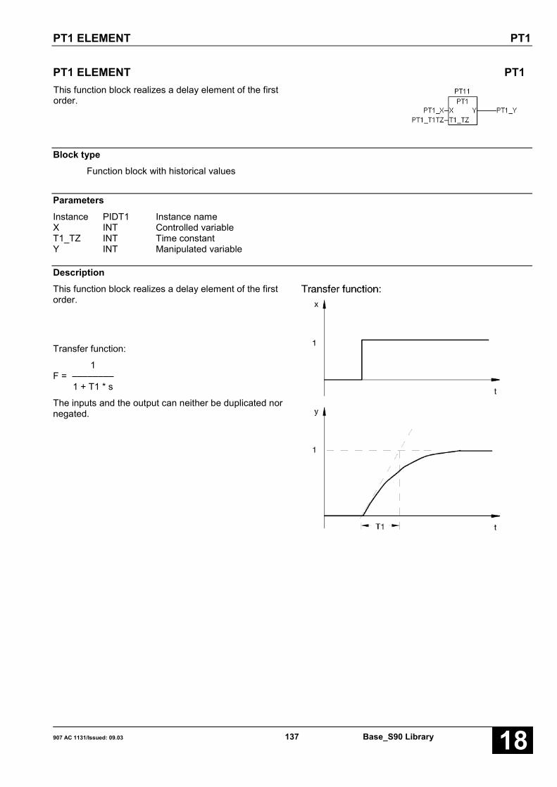
PT1 ELEMENT PT1
907 AC 1131/Issued: 09.03 137 Base_S90 Library 18
PT1 ELEMENT PT1This function block realizes a delay element of the firstorder.
Block typeFunction block with historical values
ParametersInstance PIDT1 Instance nameX INT Controlled variableT1_TZ INT Time constantY INT Manipulated variable
DescriptionThis function block realizes a delay element of the firstorder.
Transfer function:
1F = ––––––––
1 + T1 * s
The inputs and the output can neither be duplicated nornegated.

PT1 ELEMENT PT1
Base_S90 Library 138 907 AC 1131/Stand: 09.0318
X INTThe controlled variable is specified at input X.
T1_TZ INTThe delay time T1 is specified at input T1_TZ. To dothis, the delay time T1 must be normalized to the cycletime TZ.
The following must apply: T1_TZ > 0
If an incorrect negative time value is specified, the PLCautomatically sets T1_TZ to the value 32767.
Y INTThe result of the delay element (manipulated variable)is output at output Y.
Function call in ILCAL PT11(X := PT1_X, T1_TZ := PT1_T1TZ)
LD PT11.YST PT1_Y
Function call in STPT11(X := PT1_X, T1_TZ := PT1_T1TZ);PT1_Y:=PT11.Y;

SET BIT IN DOUBLE WORD SETBD
907 AC 1131/Issued: 09.03 139 Base_S90 Library 18
SET BIT IN DOUBLE WORD SETBDThe bit at input BIT is set or reset in the double word Adepending on input E. Valid values at input BIT: 0…31.
Block typeFunction block without historical values
ParametersInstance SETBD Instance nameE BOOL Input valueBIT INT Bit number of the bit to be setA DINT Output value
DescriptionThe bit at input BIT is set or reset in the double word Adepending on input E. Valid values at input BIT: 0…31.
The inputs and the output can neither be duplicated nornegated.
Function call in ILCAL SETBD1(E := SETD_E, BIT := SETD_BIT,
A := SETD_A)
Note: In IL, the function call has to be performed inone line.
Function call in STSETBD1(E := SETD_E, BIT := SETD_BIT,A := SETD_A)

SET BIT IN WORD SETBW
Base_S90 Library 140 907 AC 1131/Stand: 09.0318
SET BIT IN WORD SETBWThe bit at input BIT is set or reset in the word Adepending on input E. Valid values at input BIT: 0…15.
Block typeFunction block without historical values
ParametersInstance SETBW Instance nameE BOOL Input valueBIT INT Bit number of the bit to be setA INT Output value
DescriptionThe bit at input BIT is set or reset in the word Adepending on input E. Valid values at input BIT: 0…15.
The inputs and the output can neither be duplicated nornegated.
Function call in ILCAL SETBW1(E := SETW_E, BIT := SETW_BIT,
A := SETW_A)
Note: In IL, the function call has to be performed inone line.
Function call in STSETBW1(E := SETW_E, BIT := SETW_BIT,A := SETW_A)

SHIFT BLOCK, DOUBLE WORD SHIFTD
907 AC 1131/Issued: 09.03 141 Base_S90 Library 18
SHIFT BLOCK, DOUBLE WORD SHIFTDThis function block shifts the operand present at theinput by a specified number of bit positions to the left orright.
Block typeFunction blocl without historical values
ParametersInstance SHIFTD Instance nameE DINT Operand to be shiftedANZ INT Number of bit positions to be shiftedLKS BOOL Shift direction, left or right
LKS = FALSE → shift to rightLKS = TRUE → shift to left
ROT BOOL Shift type: ROTATEROTC BOOL Shift type: ROTATE by the CARRY FLAGSLOG BOOL Shift type: LOGICAL SHIFTSARI BOOL Shift type: ARITHMETIC SHIFTCY_E BOOL Initial value for the CARRY FLAG in case of shift type ROTCCY_A BOOL CARRY FLAG state after the shift procedureA DINT Result of the shift procedure
BeschreibungThis function block shifts the operand present at theinput by a specified number of bit positions to the left orright.
The result of the shift procedure and the CARRY flagare available at the block outputs. The operand at theinput remains unchanged.
The required shift type is planned at the inputs:
• ROT• ROTC• SLOG• SARITH
If several shift types are specified simultaneously, theapplying shift type is the one which is located furthestto the front in the sequence of the block inputs.
The block can only shift double words.
Caution:In certain circumstances, the value 8000 0000Hforbidden for arithmetic operations may be present atthis block output.
The inputs and outputs can neither be duplicated norinverted nor negated.

SHIFT BLOCK, DOUBLE WORD SHIFTD
Base_S90 Library 142 907 AC 1131/Stand: 09.0318
E DINTOperand to be shifted. The planned SHIFT operation isapplied to the input operand. In doing so, the inputoperand is not changed.
ANZ INTNumber of bit positions to be shifted.Sensible range for the quantity n:0 < n < 32
LKS BOOLDirection in which shifting is performed.
LKS = FALSE → shift to right
LKS = TRUE → shift to left
ROT BOOLShift type: ROTATE
The bit position released by the shift procedure isreplaced by the bit shifted out. The contents of theCARRY FLAG is additionally replaced by the bit shiftedout. After the shift procedure, the result and thecontents of the CARRY FLAG are available at the blockoutputs.
ROT to the right: C MSB LSBROT to the left: C MSB LSB
LSB: Least significant bitMSB: Most significant bit
ROTC BOOLShift type: ROTATE by the CARRY FLAG.
The bit position released by the shift procedure isreplaced by the contents of the CARRY FLAG. TheCARRY FLAG is then replaced by the bit shifted out.After the shift procedure, the result and the contents ofthe CARRY FLAG are available at the block outputs.
ROTC to the right: C MSB LSBROTC to the left: C MSB LSB
LSB: Least significant bitMSB: Most significant bit
SLOG BOOLShift type: LOGICAL SHIFT
The bit position released by the shift procedure isreplaced by the value 0.
The contents of the CARRY FLAG is replaced by thebit shifted out. After the shift procedure, the result andthe contents of the CARRY FLAG are available at theblock outputs.
SLOG to the right: C 0 MSB LSBSLOG to the left: C MSB LSB 0
LSB: Least significant bitMSB: Most significant bit
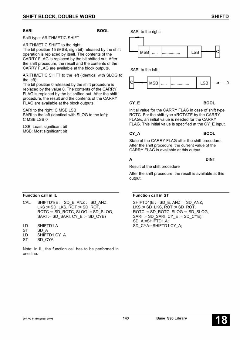
SHIFT BLOCK, DOUBLE WORD SHIFTD
907 AC 1131/Issued: 09.03 143 Base_S90 Library 18
SARI BOOLShift type: ARITHMETIC SHIFT
ARITHMETIC SHIFT to the right:The bit position 15 (MSB, sign bit) released by the shiftoperation is replaced by itself. The contents of theCARRY FLAG is replaced by the bit shifted out. Afterthe shift procedure, the result and the contents of theCARRY FLAG are available at the block outputs.
ARITHMETIC SHIFT to the left (identical with SLOG tothe left):The bit position 0 released by the shift procedure isreplaced by the value 0. The contents of the CARRYFLAG is replaced by the bit shifted out. After the shiftprocedure, the result and the contents of the CARRYFLAG are available at the block outputs.
SARI to the right: C MSB LSBSARI to the left (identical with SLOG to the left):C MSB LSB 0
LSB: Least significant bitMSB: Most significant bit
CY_E BOOLInitial value for the CARRY FLAG in case of shift typeROTC. For the shift type »ROTATE by the CARRYFLAG«, an initial value is needed for the CARRYFLAG. This initial value is specified at the CY_E input.
CY_A BOOLState of the CARRY FLAG after the shift procedure.After the shift procedure, the current value of theCARRY FLAG is available at this output.
A DINTResult of the shift procedure
After the shift procedure, the result is available at thisoutput.
Function call in ILCAL SHIFTD1(E := SD_E, ANZ := SD_ANZ,
LKS := SD_LKS, ROT := SD_ROT,ROTC := SD_ROTC, SLOG := SD_SLOG,SARI := SD_SARI, CY_E := SD_CYE)
LD SHIFTD1.AST SD_ALD SHIFTD1.CY_AST SD_CYA
Note: In IL, the function call has to be performed inone line.
Function call in STSHIFTD1(E := SD_E, ANZ := SD_ANZ,LKS := SD_LKS, ROT := SD_ROT,ROTC := SD_ROTC, SLOG := SD_SLOG,SARI := SD_SARI, CY_E := SD_CYE);SD_A:=SHIFTD1.A;SD_CYA:=SHIFTD1.CY_A;

SHIFT BLOCK, WORD SHIFTW
Base_S90 Library 144 907 AC 1131/Stand: 09.0318
SHIFT BLOCK, WORD SHIFTWThis function block shifts the operand present at theinput by a specified number of bit positions to the left orright.
Block typeFunction block without historical values
ParametersInstance SHIFTW Instance nameE INT Operand to be shiftedANZ INT Number of bit positions to be shiftedLKS BOOL Shift direction, left or right
LKS = FALSE → shift to rightLKS = TRUE → shift to left
ROT BOOL Shift type: ROTATEROTC BOOL Shift type: ROTATE by the CARRY FLAGSLOG BOOL Shift type: LOGICAL SHIFTSARI BOOL Shift type: ARITHMETIC SHIFTCY_E BOOL Initial value for the CARRY FLAG in case of shift type ROTCCY_A BOOL CARRY FLAG state after the shift procedureA INT Result of the shift procedure
DescriptionThis function block shifts the operand present at theinput by a specified number of bit positions to the left orright.
The result of the shift procedure and the CARRY flagare available at the block outputs. The operand at theinput remains unchanged.
The required shift type is planned at the inputs:
• ROT• ROTC• SLOG• SARITH
If several shift types are specified simultaneously, theapplying shift type is the one which is located furthestto the front in the sequence of the block inputs.
The block can only shift word operands.
Caution:In certain circumstances, the value 8000H forbidden forarithmetic operations may be present at this blockoutput.
The inputs and outputs can neither be duplicated norinverted nor negated.

SHIFT BLOCK, WORD SHIFTW
907 AC 1131/Issued: 09.03 145 Base_S90 Library 18
E INTOperand to be shifted. The planned SHIFT operation isapplied to the input operand. In doing so, the inputoperand is not changed.
ANZ INTNumber of bit positions to be shifted.Sensible range for the quantity n:0 < n < 32
LKS BOOLDirection in which shifting is performed.
LKS = FALSE → shift to rightLKS = TRUE → shift to left
ROT BOOLShift type: ROTATE
The bit position released by the shift procedure isreplaced by the bit shifted out. The contents of theCARRY FLAG is additionally replaced by the bit shiftedout. After the shift procedure, the result and thecontents of the CARRY FLAG are available at the blockoutputs.
ROT to the right: C MSB LSBROT to the left: C MSB LSB
LSB: Least significant bitMSB: Most significant bit
ROTC BOOLShift type: ROTATE by the CARRY FLAG.
The bit position released by the shift procedure isreplaced by the contents of the CARRY FLAG. TheCARRY FLAG is then replaced by the bit shifted out.After the shift procedure, the result and the contents ofthe CARRY FLAG are available at the block outputs.
ROTC to the right: C MSB LSBROTC to the left: C MSB LSB
LSB: Least significant bitMSB: Most significant bit
SLOG BOOLShift type: LOGICAL SHIFT
The bit position released by the shift procedure isreplaced by the value 0.
The contents of the CARRY FLAG is replaced by thebit shifted out. After the shift procedure, the result andthe contents of the CARRY FLAG are available at theblock outputs.
SLOG to the right: C 0 MSB LSBSLOG to the left: C MSB LSB 0
LSB: Least significant bitMSB: Most significant bit
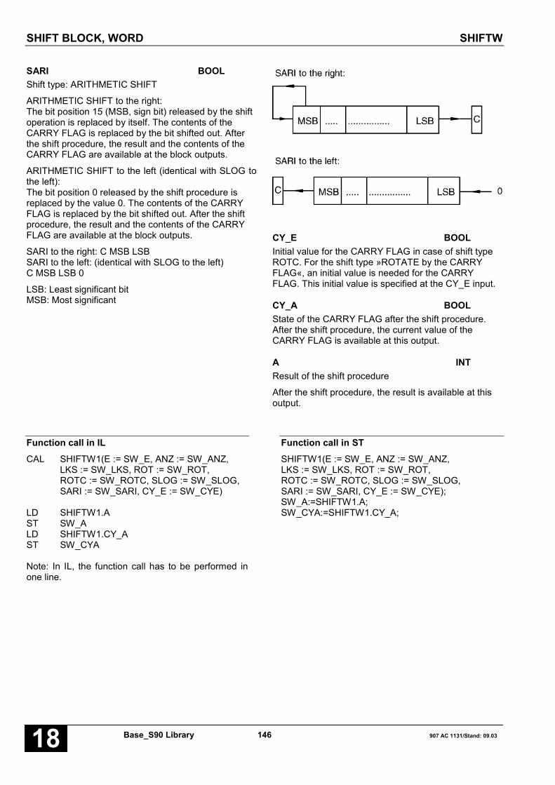
SHIFT BLOCK, WORD SHIFTW
Base_S90 Library 146 907 AC 1131/Stand: 09.0318
SARI BOOLShift type: ARITHMETIC SHIFT
ARITHMETIC SHIFT to the right:The bit position 15 (MSB, sign bit) released by the shiftoperation is replaced by itself. The contents of theCARRY FLAG is replaced by the bit shifted out. Afterthe shift procedure, the result and the contents of theCARRY FLAG are available at the block outputs.
ARITHMETIC SHIFT to the left (identical with SLOG tothe left):The bit position 0 released by the shift procedure isreplaced by the value 0. The contents of the CARRYFLAG is replaced by the bit shifted out. After the shiftprocedure, the result and the contents of the CARRYFLAG are available at the block outputs.
SARI to the right: C MSB LSBSARI to the left: (identical with SLOG to the left)C MSB LSB 0
LSB: Least significant bitMSB: Most significant
CY_E BOOLInitial value for the CARRY FLAG in case of shift typeROTC. For the shift type »ROTATE by the CARRYFLAG«, an initial value is needed for the CARRYFLAG. This initial value is specified at the CY_E input.
CY_A BOOLState of the CARRY FLAG after the shift procedure.After the shift procedure, the current value of theCARRY FLAG is available at this output.
A INTResult of the shift procedure
After the shift procedure, the result is available at thisoutput.
Function call in ILCAL SHIFTW1(E := SW_E, ANZ := SW_ANZ,
LKS := SW_LKS, ROT := SW_ROT,ROTC := SW_ROTC, SLOG := SW_SLOG,SARI := SW_SARI, CY_E := SW_CYE)
LD SHIFTW1.AST SW_ALD SHIFTW1.CY_AST SW_CYA
Note: In IL, the function call has to be performed inone line.
Function call in STSHIFTW1(E := SW_E, ANZ := SW_ANZ,LKS := SW_LKS, ROT := SW_ROT,ROTC := SW_ROTC, SLOG := SW_SLOG,SARI := SW_SARI, CY_E := SW_CYE);SW_A:=SHIFTW1.A;SW_CYA:=SHIFTW1.CY_A;
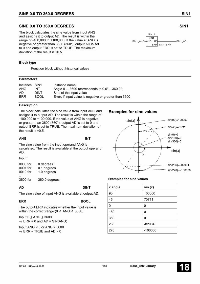
SINE 0.0 TO 360.0 DEGREES SIN1
907 AC 1131/Issued: 09.03 147 Base_S90 Library 18
SINE 0.0 TO 360.0 DEGREES SIN1The block calculates the sine value from input ANGand assigns it to output AD. The result is within therange of -100,000 to +100,000. If the value at ANG isnegative or greater than 3600 (360°), output AD is setto 0 and output ERR is set to TRUE. The maximumdeviation of the result is ±0.5.
Block typeFunction block without historical values
ParametersInstance SIN1 Instance nameANG INT Angle 0 ... 3600 (corresponds to 0.0°....360.0°)AD DINT Sine of the input valueERR BOOL Error, if input value is negative or greater than 3600
DescriptionThe block calculates the sine value from input ANG andassigns it to output AD. The result is within the range of-100,000 to +100,000. If the value at ANG is negativeor greater than 3600 (360°), output AD is set to 0 andoutput ERR is set to TRUE. The maximum deviation ofthe result is ±0.5.
ANG INTThe sine value from the input operand ANG iscalculated. The result is available at the output operandAD.
Input:
0000 for 0 degrees0001 for 0.1 degrees0010 for 1.0 degrees..3600 for 360.0 degrees
AD DINTThe sine value of input ANG is available at output AD.
ERR BOOLThe output ERR indicates whether the input value iswithin the correct range (0 < ANG < 3600).
Input 0 < ANG < 3600→ ERR = 0 and AD = SIN(ANG)
Input ANG < 0 or ANG > 3600→ ERR = TRUE and AD = 0
Examples for sine values
x angle sin (x)
90 100000
45 70711
0 0
180 0
360 0
236 -82904
270 -100000

SINE 0.0 TO 360.0 DEGREES SIN1
Base_S90 Library 148 907 AC 1131/Stand: 09.0318
Function call in ILCAL SIN11(ANG := SIN_ANG)
LD SIN11.ERRST SIN_ERRLD SIN11.ADST SIN_AD
Function call in STSIN11(ANG := SIN_ANG);SIN_ERR:=SIN11.ERR;SIN_AD:=SIN11.AD;
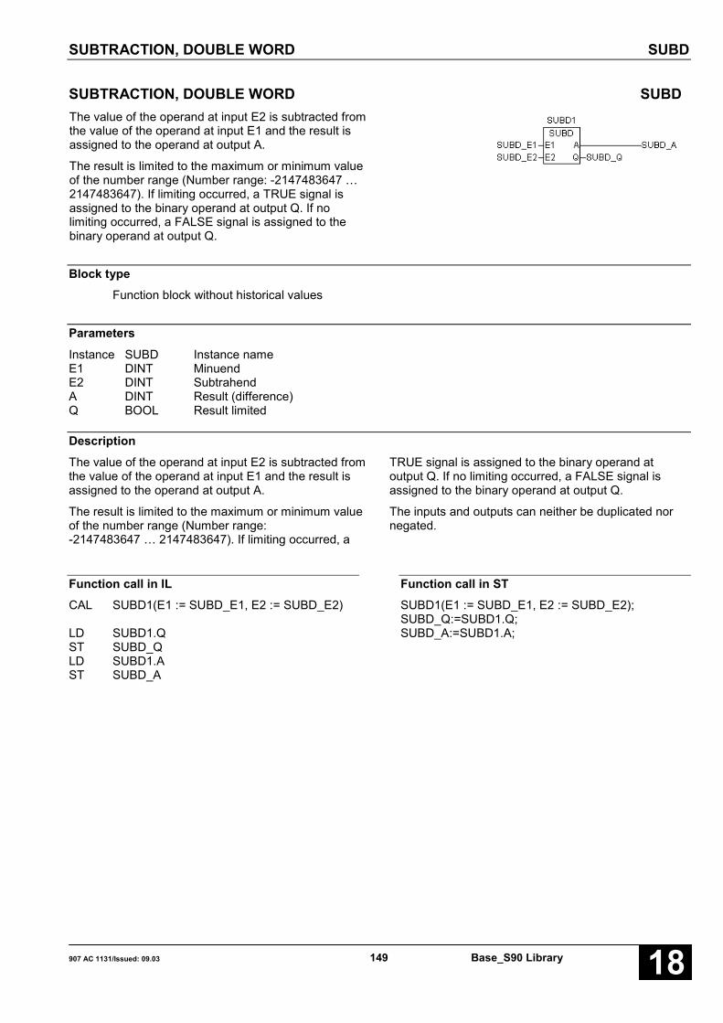
SUBTRACTION, DOUBLE WORD SUBD
907 AC 1131/Issued: 09.03 149 Base_S90 Library 18
SUBTRACTION, DOUBLE WORD SUBDThe value of the operand at input E2 is subtracted fromthe value of the operand at input E1 and the result isassigned to the operand at output A.
The result is limited to the maximum or minimum valueof the number range (Number range: -2147483647 …2147483647). If limiting occurred, a TRUE signal isassigned to the binary operand at output Q. If nolimiting occurred, a FALSE signal is assigned to thebinary operand at output Q.
Block typeFunction block without historical values
ParametersInstance SUBD Instance nameE1 DINT MinuendE2 DINT SubtrahendA DINT Result (difference)Q BOOL Result limited
DescriptionThe value of the operand at input E2 is subtracted fromthe value of the operand at input E1 and the result isassigned to the operand at output A.
The result is limited to the maximum or minimum valueof the number range (Number range:-2147483647 … 2147483647). If limiting occurred, a
TRUE signal is assigned to the binary operand atoutput Q. If no limiting occurred, a FALSE signal isassigned to the binary operand at output Q.
The inputs and outputs can neither be duplicated nornegated.
Function call in ILCAL SUBD1(E1 := SUBD_E1, E2 := SUBD_E2)
LD SUBD1.QST SUBD_QLD SUBD1.AST SUBD_A
Function call in STSUBD1(E1 := SUBD_E1, E2 := SUBD_E2);SUBD_Q:=SUBD1.Q;SUBD_A:=SUBD1.A;

SUBTRACTION, WORD SUBW
Base_S90 Library 150 907 AC 1131/Stand: 09.0318
SUBTRACTION, WORD SUBWThe value of the operand at input E2 is subtracted fromthe value of the operand at input E1 and the result isassigned to the operand at output A.
Block typeFunction
ParametersE1 INT MinuendE2 INT Subtrahend; input can be duplicatedA INT Result (difference)
DescriptionThe value of the operand at input E2 is subtracted fromthe value of the operand at input E1 and the result isassigned to the operand at output A.
The result is limited to the maximum value 32767 andthe minimum value -32767.
The inputs and the output can neither be duplicated nornegated.
Function call in ILLD SUBW_E1SUBW SUBW_E2ST SUBW_A
Function call in STSUBW_A:=SUBW(SUBW_E1, SUBW_E2);

TEST BIT IN DOUBLE WORD TESTBD
907 AC 1131/Issued: 09.03 151 Base_S90 Library 18
TEST BIT IN DOUBLE WORD TESTBDThe bit at input BIT is tested in double word andassigned to the binary variable A. Valid values at inputBIT: 0…31.
Block typeFunction
ParametersE DINT Input valueBIT INT Bit number of the bit to be testedA BOOL Output value
DescriptionThe bit at input BIT is tested in double word andassigned to the binary variable A. Valid values at inputBIT: 0…31.
The inputs and the output can neither be duplicated nornegated.
Function call in ILLD TESTD_ETESTBD TESTD_BITST TESTD_A
Function call in STTESTD_A:=TESTBD(TESTD_E, TESTD_BIT);
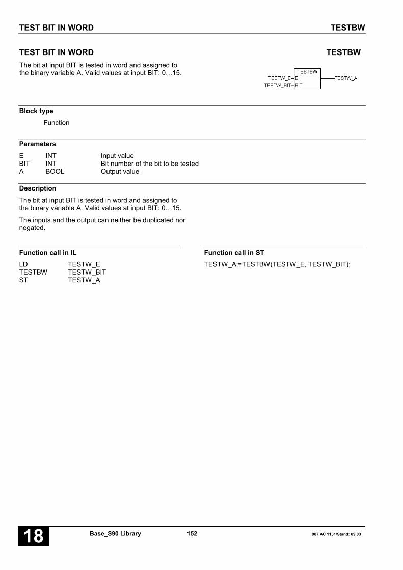
TEST BIT IN WORD TESTBW
Base_S90 Library 152 907 AC 1131/Stand: 09.0318
TEST BIT IN WORD TESTBWThe bit at input BIT is tested in word and assigned tothe binary variable A. Valid values at input BIT: 0…15.
Block typeFunction
ParametersE INT Input valueBIT INT Bit number of the bit to be testedA BOOL Output value
DescriptionThe bit at input BIT is tested in word and assigned tothe binary variable A. Valid values at input BIT: 0…15.
The inputs and the output can neither be duplicated nornegated.
Function call in ILLD TESTW_ETESTBW TESTW_BITST TESTW_A
Function call in STTESTW_A:=TESTBW(TESTW_E, TESTW_BIT);

DISPLAY AND SET CLOCK UHR
907 AC 1131/Issued: 09.03 153 Base_S90 Library 18
DISPLAY AND SET CLOCK UHRThis function block allows to set and display the currenttime and date.
Block typeFunction block with historical values
ParametersInstance UHR Instance nameFREI BOOL Enable block processingSET BOOL FALSE/TRUE edge sets the time and dateESEC INT Set input for secondsEMIN INT Set input for minutesEH INT Set input for hoursETAG INT Set input for daysEMON INT Set input for monthsEJHR INT Set input for yearsEWTG INT Set input for weekdaysAKT BOOL Topicality (usefulness) of the data at the outputsERR INT Error identifierASEC INT Output secondsAMIN INT Output minutesAH INT Output hoursATAG INT Output daysAMON INT Output monthsAJHR INT Output yearsAWTG INT Output weekday no.
DescriptionThis function block allows to set and display the currenttime and date.
The inputs and outputs can neither be duplicated norinverted nor negated.
The clock is set by means of the set inputs for the timeand date. The values present at the set inputs areadopted with the occurrence of a FALSE/TRUE edge atinput SET. As long as a TRUE signal is present at theFREI input, the current date and time are indicated atthe block’s outputs.
FREI BOOLEnabling the block
FREI = FALSE:The block is not processed. The AKT and ERR outputsare set to FALSE or 0. The time and date outputs areno longer changed by the block.FREI = TRUE: Block is processed
SET BOOLFALSE/TRUE edgeThe clock is set to the values present at the time anddate inputs.During the setting procedure the time and date at theblock outputs are invalid (output AKT = FALSE).

DISPLAY AND SET CLOCK UHR
Base_S90 Library 154 907 AC 1131/Stand: 09.0318
Set inputs for date and time
In the event of a FALSE/TRUE edge at input SET, theclock is set to the values present at the set inputs. If thespecified set values are inadmissible, the AKT output isset to FALSE and an error message appears at theERR output. In this case the values present at the timeand date outputs are invalid. The clock has to be setagain.
ESEC INTSet input for seconds.Value range: 0 … 59.
EMIN INTSet input for minutes.Value range: 0 … 59.
EH INTSet input for hours.
The clock operates in 24 hour mode, i.e. it changesfrom 23:59:59 h to 0:0:0 h.
Value range: 0 … 23.
ETAG INTSet input for days (which day of the month).
The clock knows the number of days depending on themonths and leap years. For the clock, a leap yearexists when the year number is an integral multiple of4. The maximum value for the days (28, 29, 30, 31)depends on the month.
Value range: 1…28, 29, 30, 31.
EMON INTSet input for months.Value range: 1 … 12.
EJHR INTSet input for years.The clock only indicates the years and decades.Value range: 0 … 99.
EWTG INTSet input for the number of the weekday.
This input specifies on which day of the week the inputis made. That is to say, it is possible to determinewhich day of the week the day with the number 1 is tobe (e. g. Sunday or Monday).
Value range: 1 … 7.
Example:The clock is set on Friday, 01.07.88. If the value 6 isentered for the week day number, Friday is now the 6thday of the week and Sunday is defined as the 1st dayof the week.
AKT BOOLIndication of the topicality (usefulness) of the outputs.
AKT is 1 if:
– The date and time outputs were updated in thecurrent cycle.
– The values at the outputs are consistent, i.e. none ofthe values at the date or time outputs has changedduring updating. They all originate from the sameclock pulse.
– The clock was set correctly.AKT = TRUE → ERR = 0:Date/time are valid
AKT = FALSE → ERR > 0:Date/time are invalidThe reason is displayed at output ERR as an erroridentifier.
ERR INTIn the event of an error, the relevant error identifier isavailable at output ERR.
Meanings of the error identifiers:
• No error has occurred:ERR=0: No error has occurred or FREI = FALSE,
i.e. block disabled.
• Error when setting the clock:ERR=1: 0 < SEC < 59 has not been metERR=2: 0 < MIN < 59 has not been metERR=3: 0 < H < 23 has not been metERR=4: 1 < TAG < 28, 29, 30, 31 (depending on
the month) has not been metERR=5: 1 < MON < 12 has not been metERR=6: 0 < JHR < 99 has not been metERR=7: 1 < WTG < 7 has not been metERR=8: The transmission mailbox is currently
occupied by another user. The block waitsuntil the mailbox is free and afterwardsdate/time are set.
ERR=9: Date/time at the outputs are invalid.ERR=10: Setting of date/time is currently performed;
this may take several PLC cycles.ERR=11: Setting was not successful, please repeat
(unknown request code).ERR=12: Setting was not successful, please repeat
(invalid mail parameter).ERR=13: Setting was not successful, please repeat
(request code cannot be excecuted).

DISPLAY AND SET CLOCK UHR
907 AC 1131/Issued: 09.03 155 Base_S90 Library 18
• Error when displaying date and time:ERR=9: Date/time at the outputs are invalid.
Outputs for date and timeThe outputs are updated whenever a TRUE signal ispresent at the FREI input and the clock has been setonce. During the setting the outputs for date and timeare invalid.
If the AKT output is equal to TRUE, the outputs for thedate and time are valid. In case of an error, an erroridentifier is output at output ERR.
ASEC INTOutput seconds.Value range: 0 … 59.
AMIN INTOutput minutes.Value range: 0 … 59.
AH INTOutput hours.Value range: 0 … 23.
ATAG INTOutput days.Value range: 1 … 28, 29, 30, 31.
AMON INTOutput months.Value range: 1 … 12.
AJHR INTOutput years.Value range: 0 … 99.
AWTG INTOutput weekday no.Value range: 1 … 7.
Function call in ILCAL UHR1(FREI := UHR_FREI,
SET := UHR_SET, ESEC := UHR_ESEC,EMIN := UHR_EMIN, EH := UHR_EH,ETAG := UHR_ETAG,EMON := UHR_EMON,EJHR := UHR_EJHR, EWO := UHR_EWO)
LD UHR1.ERRST UHR_ERRLD UHR1.ASECST UHR_ASECLD UHR1.AMINST UHR_AMINLD UHR1.AHST UHR_AHLD UHR1.ATAGST UHR_ATAGLD UHR1.AMONST UHR_AMONLD UHR1.AJHRST UHR_AJHRLD UHR1.AWOST UHR_AWOLD UHR1.AKTST UHR_AKT
Note: In IL, the function call has to be performed inone line.
Function call in STUHR1(FREI := UHR_FREI, SET := UHR_SET,ESEC := UHR_ESEC, EMIN := UHR_EMIN,EH := UHR_EH, ETAG := UHR_ETAG,EMON := UHR_EMON, EJHR := UHR_EJHR,EWO := UHR_EWO);UHR_ERR:=UHR1.ERR;UHR_ASEC:=UHR1.ASEC;UHR_AMIN:=UHR1.AMIN;UHR_AH:=UHR1.AH;UHR_ATAG:=UHR1.ATAG;UHR_AMON:=UHR1.AMON;UHR_AJHR:=UHR1.AJHR;UHR_AWO:=UHR1.AWO;UHR_AKT:=UHR1.AKT;

UNPACKING A WORD INTO BINARY VARIABLES UNPACK
Base_S90 Library 156 907 AC 1131/Stand: 09.0318
UNPACKING A WORD INTO BINARY VARIABLES UNPACKThis function block unpacks the word variable at inputE. Each bit of the input variable is assigned to onebinary variable each (B0 ... Bn) at the output.
Block typeFunction block without historical values
ParametersInstance UNPACK Instance nameE INT Word variable to be unpackedn INT Number of output variables B0 ... Bn-1B0..Bn BOOL Binary output variable
DescriptionThis function block unpacks the word variable at inputE. Each bit of the input variable is assigned to onebinary variable each (B0 ... Bn-1) at the output.
E INTThe variable to be unpacked is specified at input E.Each bit (bit0 ... bit15) of this input variable is assignedto the assigned output variable (B0 ... Bn-1).
n INTThe number of planned binary outputs (B0 ... Bn-1) isspecified at input n. The following applies: 1 < n < 16
B0…B15 BOOLThe assigned bits of the variable at input E areassigned to the binary outputs B0 ... B15.
Assignment:
Input variable Bit0 → B0Input variable Bit1 → B1
. . .
. . .Input variable Bit15 → B15
Function call in ILCAL UNPACK1(E := UNPACK_E, n := 3)
LD UNPACK1.B1ST UNPACK_B1LD UNPACK1.B2ST UNPACK_B2LD UNPACK1.B0ST UNPACK_B0
Function call in STUNPACK1(E := UNPACK_E, n := 3);UNPACK_B1:=UNPACK1.B1;UNPACK_B2:=UNPACK1.B2;UNPACK_B0:=UNPACK1.B0;

UNPACKING A DOUBLE WORD INTO BINARY VARIABLES UNPACKD
907 AC 1131/Issued: 09.03 157 Base_S90 Library 18
UNPACKING A DOUBLE WORD INTO BINARY VARIABLES UNPACKDThis function block unpacks the double word variable atinput E. Each bit of the input variable is assigned toone binary variable each (B0 ... Bn) at the output.
Block typeFunction block without historical values
ParametersInstance UNPACKD Instance nameE DINT Word variable to be unpackedn INT Number of output variables B0 ... Bn-1B0..Bn BOOL Binary output variable
DescriptionThis function block unpacks the double word variable atinput E. Each bit of the input variable is assigned to onebinary variable each (B0 ... Bn-1) at the output.
E DINTThe variable to be unpacked is specified at input E.Each bit (bit0 ... bit15) of this input variable is assignedto the allocated output variable (B0 ... Bn-1).
n INTThe number of planned binary outputs (B0 ... Bn-1) isspecified at input n. The following applies: 1 < n < 32
B0…B31 BOOLThe allocated bits of the variable at input E areassigned to the binary outputs B0 ... B31.
Assignment:
Input variable Bit0 → B0Input variable Bit1 → B1
. . .
. . .Input variable Bit31 → B31

UNPACKING A DOUBLE WORD INTO BINARY VARIABLES UNPACKD
Base_S90 Library 158 907 AC 1131/Stand: 09.0318
Function call in ILCAL UNPACKD1(E := UNPACKD_E, n := 3)
LD UNPACKD1.B1ST UNPACKD_B1LD UNPACKD1.B2ST UNPACKD_B2LD UNPACKD1.B0ST UNPACKD_B0
Function call in STUNPACKD1(E := UNPACKD_E, n := 3);UNPACKD_B1:=UNPACKD1.B1;UNPACKD_B2:=UNPACKD1.B2;UNPACKD_B0:=UNPACKD1.B0;
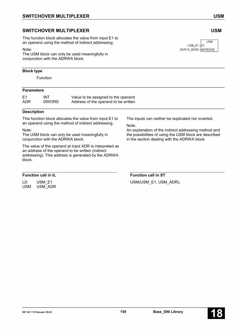
SWITCHOVER MULTIPLEXER USM
907 AC 1131/Issued: 09.03 159 Base_S90 Library 18
SWITCHOVER MULTIPLEXER USMThis function block allocates the value from input E1 toan operand using the method of indirect addressing.
Note:The USM block can only be used meaningfully inconjunction with the ADRWA block.
Block typeFunction
ParametersE1 INT Value to be assigned to the operandADR DWORD Address of the operand to be written
DescriptionThis function block allocates the value from input E1 toan operand using the method of indirect addressing.
Note:The USM block can only be used meaningfully inconjunction with the ADRWA block.
The value of the operand at input ADR is interpreted asan address of the operand to be written (indirectaddressing). This address is generated by the ADRWAblock.
The inputs can neither be duplicated nor inverted.
Note:An explanation of the indirect addressing method andthe possibilities of using the USM block are describedin the section dealing with the ADRWA block.
Function call in ILLD USM_E1USM USM_ADR
Function call in STUSM(USM_E1, USM_ADR);

SWITCHOVER GATE UST
Base_S90 Library 160 907 AC 1131/Stand: 09.0318
SWITCHOVER GATE USTA FALSE signal at the binary input E0_1 assigns thevalue of the word operand at input E1 to the wordoperand at output A0.
A TRUE signal at the binary input E0_1 assigns thevalue of the word operand at input E1 to the wordoperand at output A1.
The respective output that is not assigned keeps its oldvalue, but the old value is not updated.
Block typeFunction block without historical values
ParametersInstance UST Instance nameE0_1 BOOL Switchover inputE1 INT InputA0 INT Output for E0_1 = FALSEA1 INT Output for E0_1 = TRUE
DescriptionA FALSE signal at the binary input E0_1 assigns thevalue of the word operand at input E1 to the wordoperand at output A0.
A TRUE signal at the binary input E0_1 assigns thevalue of the word operand at input E1 to the wordoperand at output A1.
The respective output that is not assigned keeps its oldvalue, but the old value is not updated.
The inputs and outputs can neither be duplicated nornegated/inverted.
Function call in ILCAL UST1(E0_1 := UST_E01, E1 := UST_E1)
LD UST1.A1ST UST_A1LD UST1.A0ST UST_A0
Function call in STUST1(E0_1 := UST_E01, E1 := UST_E1);UST_A1:=UST1.A1;UST_A0:=UST1.A0;

SWITCHOVER GATE / DOUBLE WORD USTD
907 AC 1131/Issued: 09.03 161 Base_S90 Library 18
SWITCHOVER GATE / DOUBLE WORD USTDA FALSE signal at the binary input E0_1 assigns thevalue of the double word operand at input E1 to theword operand at output A0.
A TRUE signal at the binary input E0_1 assigns thevalue of the double word operand at input E1 to theword operand at output A1.
The respective output that is not assigned keeps its oldvalue, but the old value is not updated.
Block typeFunction block without historical values
ParametersInstance USTD Instance nameE0_1 BOOL Switchover inputE1 DINT InputA0 DINT Output for E0_1 = FALSEA1 DINT Output for E0_1 = TRUE
DescriptionA FALSE signal at the binary input E0_1 assigns thevalue of the double word operand at input E1 to theword operand at output A0.
A TRUE signal at the binary input E0_1 assigns thevalue of the double word operand at input E1 to theword operand at output A1.
The respective output that is not assigned keeps its oldvalue, but the old value is not updated.
The inputs and outputs can neither be duplicated nornegated/inverted.
Function call in ILCAL USTD1(E0_1 := USTD_E01,
E1 := USTD_E1)
LD USTD1.A1ST USTD_A1LD USTD1.A0ST USTD_A0
Function call in STUSTD1(E0_1 := USTD_E01, E1 := USTD_E1);USTD_A1:=USTD1.A1;USTD_A0:=USTD1.A0;
Note: In IL, the function call has to be performed in one line.
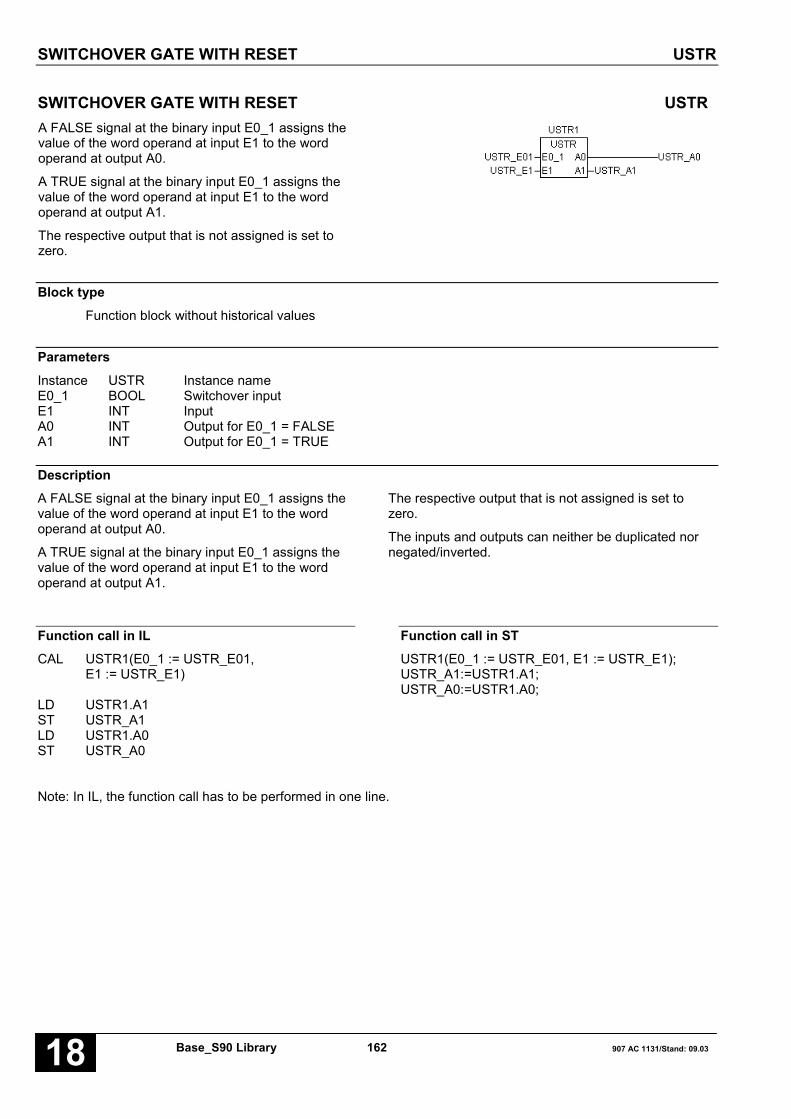
SWITCHOVER GATE WITH RESET USTR
Base_S90 Library 162 907 AC 1131/Stand: 09.0318
SWITCHOVER GATE WITH RESET USTRA FALSE signal at the binary input E0_1 assigns thevalue of the word operand at input E1 to the wordoperand at output A0.
A TRUE signal at the binary input E0_1 assigns thevalue of the word operand at input E1 to the wordoperand at output A1.
The respective output that is not assigned is set tozero.
Block typeFunction block without historical values
ParametersInstance USTR Instance nameE0_1 BOOL Switchover inputE1 INT InputA0 INT Output for E0_1 = FALSEA1 INT Output for E0_1 = TRUE
DescriptionA FALSE signal at the binary input E0_1 assigns thevalue of the word operand at input E1 to the wordoperand at output A0.
A TRUE signal at the binary input E0_1 assigns thevalue of the word operand at input E1 to the wordoperand at output A1.
The respective output that is not assigned is set tozero.
The inputs and outputs can neither be duplicated nornegated/inverted.
Function call in ILCAL USTR1(E0_1 := USTR_E01,
E1 := USTR_E1)
LD USTR1.A1ST USTR_A1LD USTR1.A0ST USTR_A0
Function call in STUSTR1(E0_1 := USTR_E01, E1 := USTR_E1);USTR_A1:=USTR1.A1;USTR_A0:=USTR1.A0;
Note: In IL, the function call has to be performed in one line.
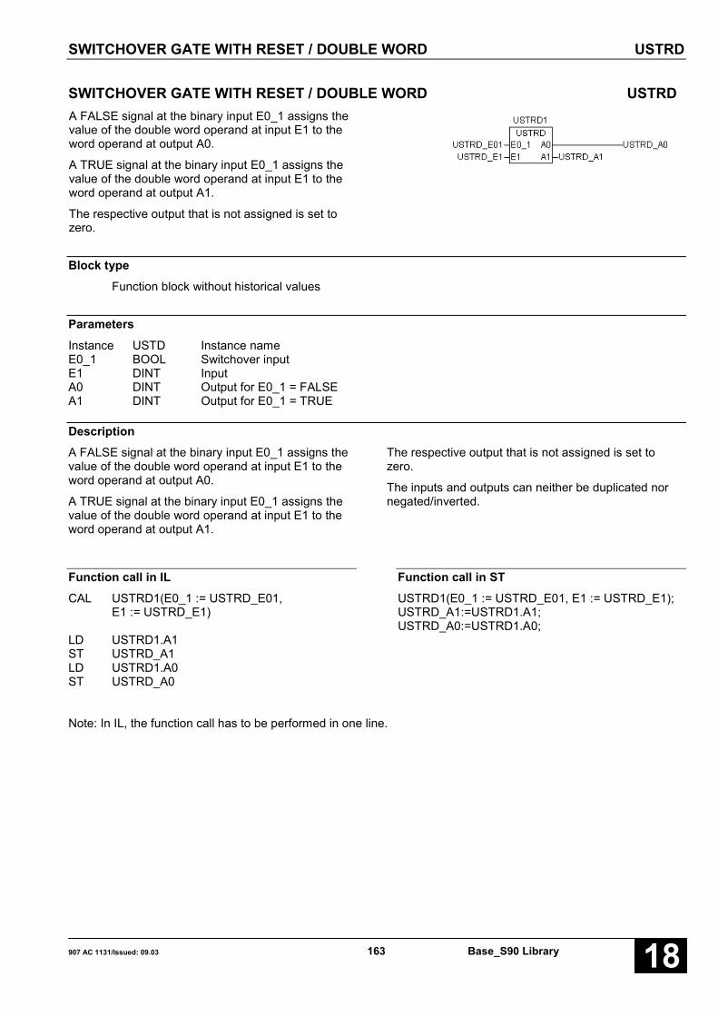
SWITCHOVER GATE WITH RESET / DOUBLE WORD USTRD
907 AC 1131/Issued: 09.03 163 Base_S90 Library 18
SWITCHOVER GATE WITH RESET / DOUBLE WORD USTRDA FALSE signal at the binary input E0_1 assigns thevalue of the double word operand at input E1 to theword operand at output A0.
A TRUE signal at the binary input E0_1 assigns thevalue of the double word operand at input E1 to theword operand at output A1.
The respective output that is not assigned is set tozero.
Block typeFunction block without historical values
ParametersInstance USTD Instance nameE0_1 BOOL Switchover inputE1 DINT InputA0 DINT Output for E0_1 = FALSEA1 DINT Output for E0_1 = TRUE
DescriptionA FALSE signal at the binary input E0_1 assigns thevalue of the double word operand at input E1 to theword operand at output A0.
A TRUE signal at the binary input E0_1 assigns thevalue of the double word operand at input E1 to theword operand at output A1.
The respective output that is not assigned is set tozero.
The inputs and outputs can neither be duplicated nornegated/inverted.
Function call in ILCAL USTRD1(E0_1 := USTRD_E01,
E1 := USTRD_E1)
LD USTRD1.A1ST USTRD_A1LD USTRD1.A0ST USTRD_A0
Function call in STUSTRD1(E0_1 := USTRD_E01, E1 := USTRD_E1);USTRD_A1:=USTRD1.A1;USTRD_A0:=USTRD1.A0;
Note: In IL, the function call has to be performed in one line.

COMPARATOR WITH 3-POINT RESPONSE VGL3P
Base_S90 Library 164 907 AC 1131/Stand: 09.0318
COMPARATOR WITH 3-POINT RESPONSE VGL3PThe value of the operand at input E is compared to thevalues of the operands at the inputs OG and UG.
The possible results are signaled at the outputs E_OG,E_UG and Q.
The following applies:
E < UG→ E_OG = FALSE, E_UG = TRUE, Q = FALSEUG < E < OG→ E_OG = FALSE, E_UG = FALSE, Q = TRUEE > OG→ E_OG = TRUE, E_UG = FALSE, Q = FALSE
Block typeFunction block without historical values
ParametersInstance VGL3P Instance nameE INT Input valueOG INT High limitUG INT Low limitE_OG BOOL Value > high limitE_UG BOOL Value < low limitQ BOOL Low limit < input value < high limit
DescriptionThe value of the operand at input E is compared to thevalues of the operands at the inputs OG and UG.
The possible results are signaled at the outputs E_OG,E_UG and Q.
The following applies:
E < UG→ E_OG = FALSE, E_UG = TRUE, Q = FALSEUG < E < OG→ E_OG = FALSE, E_UG = FALSE, Q = TRUEE > OG→ E_OG = TRUE, E_UG = FALSE, Q = FALSE
The inputs and outputs can neither be duplicated nornegated.

COMPARATOR WITH 3-POINT RESPONSE VGL3P
907 AC 1131/Issued: 09.03 165 Base_S90 Library 18
Function call in ILCAL VGL3P1(E := V3P_E, OG := V3P_OG,
UG := V3P_UG)
LD VGL3P1.E_UGST V3P_EUGLD VGL3P1.QST V3P_QLD VGL3P1.E_OGST V3P_EOG
Note: In IL, the function call has to be performed inone line.
Function call in STVGL3P1(E := V3P_E, OG := V3P_OG,UG := V3P_UG);V3P_EUG:=VGL3P1.E_UG;V3P_Q:=VGL3P1.Q;V3P_EOG:=VGL3P1.E_OG;

COMPARATOR WITH UNILATERAL HYSTERESIS VGLEH
Base_S90 Library 166 907 AC 1131/Stand: 09.0318
COMPARATOR WITH UNILATERAL HYSTERESIS VGLEHThe values of the operands at the inputs E1 and E2 arecompared to each other. Taking the hysteresis at inputHSY into account, the result is signaled at output Q.
The following applies:
E1 > E2 → Q = TRUEE1 < E2 - HYS → Q = FALSEE2 - HYS < E1 < E2
→ Q as in the previous cycle
Block typeFunction block with historical values
ParametersInstance VGLEH Instance nameE1 INT Input value 1E2 INT Input value 2HYS INT HysteresisQ BOOL Result of the comparison
Description see next page

COMPARATOR WITH UNILATERAL HYSTERESIS VGLEH
907 AC 1131/Issued: 09.03 167 Base_S90 Library 18
The values of the operands at the inputs E1 and E2 arecompared to each other. Taking the hysteresis at inputHSY into account, the result is signaled at output Q.
The following applies:
E1 ≥ E2→ Q = 1
E1 < E2 – HYS→ Q = FALSE
E2 - HYS ≤ E1 < E2→ Q as in the previous cycle
The inputs can neither be duplicated nor inverted. Theoutput can neither be duplicated nor inverted.
Number rangeInteger word (16 bits)• Low limit: 8001H 32767• High limit: 7FFFH +32767• Inadmissible value: 8000H ---
The following especially applies here to thespecification for the left edge of the hysteresis:E2 - HYS > -32767 (8001H)
In the two’s complement arithmetic, the value 8000H(-32768) lies outside of the number range and is neithergenerated nor processed correctly by the PLC. If thisforbidden value reaches the PLC• by bit manipulations of the user or• by reading from outside the PLC or• by an indirect word constant
it is absolutely not allowed to carry out a negation orsubtraction on this value.
Function call in ILCAL VGLEH1(E1 := VEH_E1, E2 := VEH_E2,
HYS := VEH_HYS)
LD VGLEH1.QST VEH_Q
Note: In IL, the function call has to be performed inone line.
Function call in STVGLEH1(E1 := VEH_E1, E2 := VEH_E2,HYS := VEH_HYS);VEH_Q:=VGLEH1.Q;

COMPARATOR WITH ASYMMETRICAL HYSTERESIS VGLUH
Base_S90 Library 168 907 AC 1131/Stand: 09.0318
COMPARATOR WITH ASYMMETRICAL HYSTERESIS VGLUHThe values of the operands at the inputs E1 and E2 arecompared to each other. Taking the hystereses at theinputs OHYS (high hysteresis) and UHYS (lowhysteresis) into account, the result is signaled at outputQ.
The following applies:
E1 < E2 – UHYS→ Q = FALSE
E1 ≥ E2 + OHYS→ Q = TRUE
E2 - UHYS ≤ E1 ≤ E2 + OHYS→ Q as in the previous cycle
Block typeFunction block with historical values
ParametersInstance VGLUH Instance nameE1 INT Input value 1E2 INT Input value 2OHYS INT High hysteresisUHYS INT Low hysteresisQ BOOL Result of the comparison
Description see next page

COMPARATOR WITH ASYMMETRICAL HYSTERESIS VGLUH
907 AC 1131/Issued: 09.03 169 Base_S90 Library 18
The values of the operands at the inputs E1 and E2 arecompared to each other. Taking the hystereses at theinputs OHYS (high hysteresis) and UHYS (lowhysteresis) into account, the result is signaled at outputQ.
The following applies:
E1 < E2 – UHYS→ Q = FALSE
E1 ≥ E2 + OHYS→ Q = 1
E2 - UHYS ≤ E1 ≤ E2 + OHYS→ Q as in the previous cycle
The inputs can neither be duplicated nor inverted. Theoutput can neither be duplicated nor inverted.
Number rangeInteger word (16 bits)• Low limit: 8001H 32767• High limit: 7FFFH +32767• Inadmissible value: 8000H ---
The following especially applies here to thespecification for the left edge of the hysteresis:
E2 - HYS > -32767 (8001H)
In the two’s complement arithmetic, the value 8000H(-32768) lies outside of the number range and is neithergenerated nor processed correctly by the PLC. If thisforbidden value reaches the PLC• by bit manipulations of the user or• by reading from outside the PLC or• by an indirect word constant
it is absolutely not allowed to carry out a negation orsubtraction on this value.
Function call in ILCAL VGLUH1(E1 := VUH_E1, E2 := VUH_E2,
OHYS := VUH_OHYS,UHYS := VUH_UHYS)
LD VGLUH1.QST VUH_Q
Note: In IL, the function call has to be performed inone line.
Function call in STVGLUH1(E1 := VUH_E1, E2 := VUH_E2,OHYS := VUH_OHYS, UHYS := VUH_UHYS);VUH_Q:=VGLUH1.Q;

UP-DOWN COUNTER VRZ
Base_S90 Library 170 907 AC 1131/Stand: 09.0318
UP-DOWN COUNTER VRZThis function block is used to count pulses. Duringcounting, the positive edge of the pulse is evaluated ineach case. The counter is capable of counting up anddown and the counting increment can be specified. It ispossible to preset the counter content to anintermediate value.
Block typeFunction block with historical values
ParametersInstance VRZ Instance nameFREI BOOL Enabling of the block processingZV BOOL Pulse input, up countingZR BOOL Pulse input, down countingDIFF INT Counter content change per positive edge (increment)SET BOOL Set counter to an intermediate valueZW INT Intermediate valueRES BOOL Reset counterZ INT Output for counter content
DescriptionThis function block is used to count pulses. Duringcounting, the positive edge of the pulse is evaluated ineach case. The counter is capable of counting up anddown and the counting increment can be specified. It ispossible to preset the counter content to anintermediate value.
FREI BOOLCounting is enabled or disabled by means of the FREIinput.
The following applies:
FREI = FALSE → Counting disabledFREI = TRUE → Counting enabled
ZV BOOL
Each positive edge (FALSE → TRUE edge) at the inputZV increases the current counter content by theincrement specified at input DIFF.
ZR BOOL
Each positive edge (FALSE → TRUE edge) at the inputZR decreases the current counter content by theincrement specified at input DIFF.
DIFF INT
The increment for the counting operation is specified atinput DIFF. The increment is the value by which thecounter is changed at the input ZV or ZR with eachpositive edge.
SET BOOLBy means of a TRUE signal at input SET, the countercontent is set to the value specified at input ZW.Counting is blocked as long as a TRUE signal ispresent at input SET. Setting is also effective when aTRUE signal is present at input FREI.
ZW INTThe value to which the counter content is set by aTRUE signal at input SET is specified at the input ZW.
RES BOOLA TRUE signal at input RES sets the counter content tothe value 0. The reset input RES has the highestpriority of all inputs.
Z INTThe current counter content is available at output Z.
If the counter reaches the positive or negative limit ofthe number range, the counter is limited to this value.The inputs and the output can neither be duplicated nornegated/inverted.

UP-DOWN COUNTER VRZ
907 AC 1131/Issued: 09.03 171 Base_S90 Library 18
Function call in ILCAL VRZ1(FREI := VRZ_FREI, ZV := VRZ_ZV,
ZR := VRZ_ZR, DIFF := VRZ_DIFF,SET := VRZ_SET, ZW := VRZ_ZW,RESET := VRZ_RES)
LD VRZ1.AST VRZ_A
Note: In IL, the function call has to be performed inone line.
Function call in STVRZ1(FREI := VRZ_FREI, ZV := VRZ_ZV,ZR := VRZ_ZR, DIFF := VRZ_DIFF,SET := VRZ_SET, ZW := VRZ_ZW,RESET := VRZ_RES);VRZ_A:=VRZ1.A;

UP-DOWN COUNTER / DOUBLE WORD VRZD
Base_S90 Library 172 907 AC 1131/Stand: 09.0318
UP-DOWN COUNTER / DOUBLE WORD VRZDThis function block is used to count pulses. Duringcounting, the positive edge of the pulse is evaluated ineach case. The counter is capable of counting up anddown and the counting increment can be specified. It ispossible to preset the counter content to anintermediate value.
Block typeFunction block with historical values
ParametersInstance VRZD Instance nameFREI BOOL Enabling of the block processingZV BOOL Pulse input, up countingZR BOOL Pulse input, down countingDIFF DINT Counter content change per positive edge (increment)SET BOOL Set counter to an intermediate valueZW DINT Intermediate valueRES BOOL Reset counterZ DINT Output for counter content
DescriptionThis function block is used to count pulses. Duringcounting, the positive edge of the pulse is evaluated ineach case. The counter is capable of counting up anddown and the counting increment can be specified. It ispossible to preset the counter content to anintermediate value.
FREI BOOLCounting is enabled or disabled by means of the FREIinput.
The following applies:
FREI = FALSE → Counting disabledFREI = TRUE → Counting enabled
ZV BOOL
Each positive edge (FALSE → TRUE edge) at input ZVincreases the current counter content by the incrementspecified at input DIFF.
ZR BOOL
Each positive edge (FALSE → TRUE edge) at input ZRdecreases the current counter content by the incrementspecified at input DIFF.
DIFF DINT
The increment for the counting operation is specified atinput DIFF. The increment is the value by which thecounter is changed at input ZV or ZR with each positiveedge.
SET BOOLBy means of a TRUE signal at input SET, the countercontent is set to the value specified at the input ZW.Counting is blocked as long as a TRUE signal ispresent at input SET. Setting is also effective when aTRUE signal is present at input FREI.
ZW DINTThe value to which the counter content is set by aTRUE signal at input SET is specified at the input ZW.
RES BOOLA TRUE signal at input RES sets the counter content tothe value 0. The reset input RES has the highestpriority of all inputs.
Z DINTThe current counter content is available at output Z.
If the counter reaches the positive or negative limit ofthe number range, the counter is limited to this value.The inputs and the output can neither be duplicated nornegated/inverted.

UP-DOWN COUNTER / DOUBLE WORD VRZD
907 AC 1131/Stand: 09.03 173 Base_S90-Bibliothek 18
Function call in ILCAL VRZD1(FREI := VRZD_FREI, ZV :=VRZD_ZV,
ZR := VRZD_ZR, DIFF := VRZD_DIFF,SET := VRZD_SET, ZW := VRZD_ZW,RESET := VRZD_RES)
LD VRZD1.AST VRZD_A
Note: In IL, the function call has to be performed inone line.
Function call in STVRZD1(FREI := VRZD_FREI, ZV := VRZD_ZV,ZR := VRZD_ZR, DIFF := VRZD_DIFF,SET := VRZD_SET, ZW := VRZD_ZW,RESET := VRZD_RES);VRZD_A:=VRZD1.A;

VARIABLE DELAY ELEMENT VVZ
Base_S90 Library 174 907 AC 1131/Stand: 09.0318
VARIABLE DELAY ELEMENT VVZA FALSE/TRUE edge at input E is delayed by the timeT_EIN and output at output Q. A subsequentFALSE/TRUE edge at input E is delayed by the timeT_AUS and output at output Q.
If input E returns to the FALSE level before the timeT_EIN is expired, output A remains in the FALSE level.If input E returns to the TRUE level before the timeT_AUS is expired, output A remains in the TRUE level.
Maximum time offset at the output: < 1 cycle time
Block typeFunction block with historical values
ParametersInstance VVZ Instance nameE BOOL Input signalT_EIN TIMER Delay time 0/1 edgeT_AUS TIMER Delay time 1/0 edgeA BOOL Output signal
DescriptionA FALSE/TRUE edge at input E is delayed by the timeT_EIN and output at output Q. A subsequentFALSE/TRUE edge at input E is delayed by the timeT_AUS and output at output Q.
If input E returns to the FALSE level before the timeT_EIN is expired, output A remains in the FALSE level.If input E returns to the TRUE level before the timeT_AUS is expired, output A remains in the TRUE level.
Maximum time offset at the output: < 1 cycle time
The inputs and the output can neither be duplicated norinverted.
General behavior� Started timers are processed by the PLC’s operating
system and are therefore completely independent ofthe PLC program processing. The operating systemdoes not issue a corresponding message to thecorresponding timer block in the PLC program untilthe timer has elapsed.
Function call in ILCAL VVZ1(E := VVZ_E, T_EIN := T#200ms,
T_AUS := T#300ms)
LD VVZ1.AST VVZ_A
Note: In IL, the function call has to be performed inone line.
Function call in STVVZ1(E := VVZ_E, T_EIN := T#200ms,T_AUS := T#300ms);VVZ_A:=VVZ1.A;

TWO WORDS INTO DOUBLE WORD CONVERSION W2WDW
907 AC 1131/Stand: 09.03 175 Base_S90-Bibliothek 18
TWO WORDS INTO DOUBLE WORD CONVERSION W2WDWThis block packs two words into a double word.
Block typeFunction
ParametersMSW INT Input higher significant wordLSW INT Input lower significant wordDW DINT Output double word
DescriptionWith this block it is possible to pack two 16 bit wordsinto a 32 bit double word. For example, this isnecessary to transfer double words or to evaluate eventtiming marks.
The flag words must be specified directly at the inputsMSW and LSW. Data errors can occur, if theassignment is performed via intermediate flags(correction of the value 8000H).
Please note that for data records sent by MasterPiecesystems the higher significant word is assigned to thelower address.
MSW INTAt input MSW, the higher significant word is output.
LSW INTAt input LSW, the lower significant word is output.
DW DINTAt output DW, the double word to be split up isspecified.
Function call in ILLD WDW_MSWW2WDW WDW_LSWST WDW_DW
Function call STWDW_DW := W2WDW(WDW_MSW, WDW_LSW);

WRITE WORD IN THE EVENT OF VALUE CHANGE WAES
Base_S90 Library 176 907 AC 1131/Stand: 09.0318
WRITE WORD IN THE EVENT OF VALUE CHANGE WAESIf the value of the operand at input E1 changes incomparison with the value during previous processingof the block, the value of the operand at input E1 iswritten to the specified physical address.
Block typeFunction block with historical values
ParametersInstance WAES Instance nameE1 INT Input for the operand to be readADRESSE DWORD 32 bit address of the memory location to which the value of E1
must be written in the event of a change.
DescriptionIf the value of the operand at input E1 changes incomparison with the value during previous processingof the block, the value of the operand at input E1 iswritten to the specified physical address.
The inputs can neither be duplicated nor inverted.
E1 INTIf the operand at input E1 changes, its value is writtento the address specified at input ADRESSE.
ADRESSE DWORDThe 32 bit address to be written is specified at inputADRESSE.
Function call in ILLD WAES_MWADRST WAES1.ADRESSECAL WAES1(E1 := WAES_E1)
Function call in STWAES1.ADRESSE:=ADR(WAES_MW);WAES1(E1 := WAES_E1);

WORD DECODER WDEC(8…256)
907 AC 1131/Stand: 09.03 177 Base_S90-Bibliothek 18
WORD DECODER WDEC(8…256)This block compares the value of the operand at inputE to the reference values of the operands at the inputsEC0 ... ECn-1. The result of the comparison is signaledat the outputs.
The WDEC number indicates the maximum number ofreference values. The following word decoders areavailable:
WDEC8 Word decoder with a maximum of 8reference values
WDEC16 Word decoder with a maximum of 16reference values
WDEC32 Word decoder with a maximum of 32reference values
WDEC64 Word decoder with a maximum of 64reference values
WDEC256 Word decoder with a maximum of 256reference values
Block typeFunction block without historical values
ParametersInstance WDEC(8..256) Instance nameE INT InputN INT Number of reference valuesEC0..ECn-1 INT Reference valuesE=EC BOOL Coincidence indicationNR INT Number of the reference value in the event of coincidence
DescriptionThe WDEC number indicates the maximum number ofreference values. The following word decoders areavailable:
WDEC8 Word decoder with a maximum of 8reference values
WDEC16 Word decoder with a maximum of 16reference values
WDEC32 Word decoder with a maximum of 32reference values
WDEC64 Word decoder with a maximum of 64reference values
WDEC256 Word decoder with a maximum of 256reference values
This block compares the value of the operand at inputE to the reference values of the operands at the inputsEC0 ... ECn-1. The result of the comparison is signaledat the outputs.
If input E agrees with at least one of the n referencevalues EC, output E=EC is set to TRUE. The number ofthe 1st reference value EC agreeing with input E is
assigned to the operand at output NR. Therefore, thenumber may assume a value from 1 to n.The outputs E=EC and NR are set to 0 if no agreementbetween the input value E and the reference value ECis determined.The number of inputs EC must be specified at input n.
E INTThe operand whose value is to be compared to thereference values of the inputs EC0 ... ECn-1 isspecified at input E.
n INTThe number of planned reference values is specified atinput n.

WORD DECODER WDEC(8…256)
Base_S90 Library 178 907 AC 1131/Stand: 09.0318
EC0 … ECn-1 INTThe operands for the reference values are specified atthe inputs EC0 ... ECn-1. The value of the operand atinput E is compared to this reference values.
E=EC BOOLAgreement (coincidence) between the operand value ofinput E and one of the reference values is signaled atoutput E=EC.
The following applies:
E=EC = FALSE → No agreement (coincidence)
E=EC = TRUE → Agreement (coincidence)
NR INTThe number of the reference value that agrees with thevalue of the operand at input E is signaled at outputNR.
The following applies:
No agreement (coincidence) → NR = 0Agreement (coincidence) → NR = n where n > 1
E=EC0 → NR = 1E=EC1 → NR = 2. . .. . .E=ECn-1 → NR = n
Function call in ILCAL WDEC1(E := WDEC_E, n := 3,
EC0 := WDEC_EC0, EC1 := WDEC_EC1,EC2 := WDEC_EC2)
LD WDEC1.NRST WDEC_NRLD WDEC1.E_ECST WDEC_EEC
Note: In IL, the function call has to be performed inone line.
Function call in STWDEC1(E := WDEC_E, n := 3, EC0 := WDEC_EC0,EC1 := WDEC_EC1, EC2 := WDEC_EC2);WDEC_NR:=WDEC1.NR;WDEC_EEC:=WDEC1.E_EC;

WORD TO DOUBLE WORD CONVERSION WDW
907 AC 1131/Stand: 09.03 179 Base_S90-Bibliothek 18
WORD TO DOUBLE WORD CONVERSION WDWThe value of the word operand at input E is convertedto a double word variable and the result is assigned tothe double word operand at output A.
Block typeFunction
ParametersE INT Word variable to be convertedA DINT Result of the conversion, double word variable
DescriptionThe value of the word operand at input E is convertedto a double word variable and the result is assigned tothe double word operand at output A.
Value range for E1:8000H < E1 < 7FFFH-32768 < E1 < 32767
The input and the output can neither be duplicated nornegated.
Function call in ILLD WDW_EWDWST WDW_DW
Function call in STWDW_DW := WDW(WDW_E);
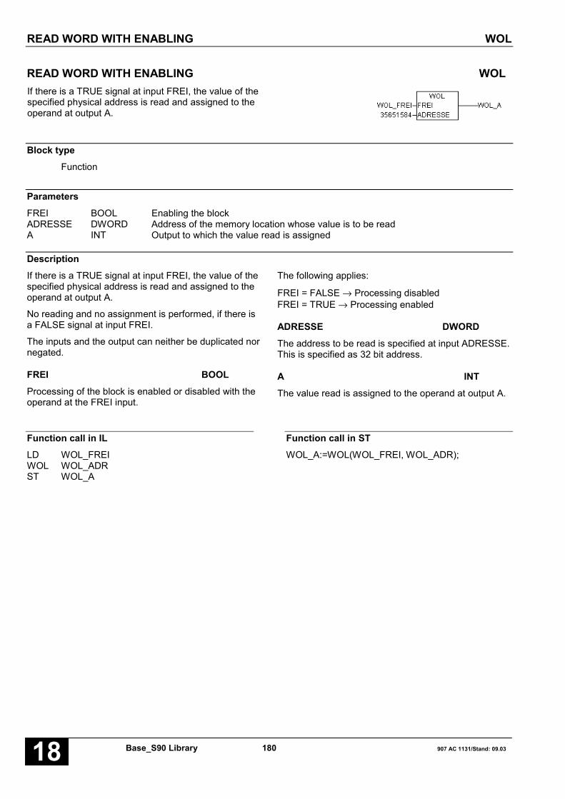
READ WORD WITH ENABLING WOL
Base_S90 Library 180 907 AC 1131/Stand: 09.0318
READ WORD WITH ENABLING WOLIf there is a TRUE signal at input FREI, the value of thespecified physical address is read and assigned to theoperand at output A.
Block typeFunction
ParametersFREI BOOL Enabling the blockADRESSE DWORD Address of the memory location whose value is to be readA INT Output to which the value read is assigned
DescriptionIf there is a TRUE signal at input FREI, the value of thespecified physical address is read and assigned to theoperand at output A.
No reading and no assignment is performed, if there isa FALSE signal at input FREI.
The inputs and the output can neither be duplicated nornegated.
FREI BOOLProcessing of the block is enabled or disabled with theoperand at the FREI input.
The following applies:
FREI = FALSE → Processing disabledFREI = TRUE → Processing enabled
ADRESSE DWORDThe address to be read is specified at input ADRESSE.This is specified as 32 bit address.
A INTThe value read is assigned to the operand at output A.
Function call in ILLD WOL_FREIWOL WOL_ADRST WOL_A
Function call in STWOL_A:=WOL(WOL_FREI, WOL_ADR);

WRITE WORD WITH ENABLING WOS
907 AC 1131/Stand: 09.03 181 Base_S90-Bibliothek 18
WRITE WORD WITH ENABLING WOSIf there is a TRUE signal at input FREI, the value of theoperand at input E1 is read and then written to thespecified physical address.
Block typeFunction
ParametersFREI BOOL Enabling the blockE1 INT Input for the operand to be writtenADRESSE DWORD Address of the memory location to which the value of E1 must
be written
DescriptionIf there is a TRUE signal at input FREI, the value of theoperand at input E1 is read and then written to thespecified physical address.
The block is not processed if there is a FALSE signal atinput FREI.
The inputs can neither be duplicated nor inverted.
FREI BOOLProcessing of the block is enabled or disabled with theoperand at input FREI.
The following applies:
FREI = FALSE → Processing disabled
FREI = TRUE → Processing enabled
E1 INTThe operand at input E1 is read and its value is writtento the defined physical address.
ADRESSE DWORDThe address to be written is specified at inputADRESSE.
Function call in ILLD WOS_FREIWOS WOS_E1,WOS_ADR
Note: In IL, the function call has to be performed inone line.
Function call in STWOS(WOS_FREI, WOS_E1, WOS_ADR);

WORD RECODER WUMC(8…256)
Base_S90 Library 182 907 AC 1131/Stand: 09.0318
WORD RECODER WUMC(8…256)This block compares the value of the operand at inputE to the reference values of the operands at the inputsEC0 ... ECn-1. If input E agrees with at least one of thereference values EC, output E=EC is set to TRUE.Output A receives the value of the output code ACwhich is assigned to the found reference value EC.
The WUMC number indicates the maximum number ofreference values. The following word recoders areavailable:
WUMC8 Word recoder with a maximum of 8reference values
WUMC16 Word recoder with a maximum of 16reference values
WUMC32 Word recoder with a maximum of 32reference values
WUMC64 Word recoder with a maximum of 64reference values
WUMC256 Word recoder with a maximum of 256reference values
Block typeFunction block without historical values
ParametersInstance WUMC(8..256) Instance nameE INT InputN INT Number n of reference valuesEC0..ECn-1 INT Reference valueAC0..ECn-1 INT Output codeE=EC BOOL Coincidence indicationA INT Output of the output code’s value
DescriptionThe WUMC number indicates the maximum numberof reference values. The following word recoders areavailable:
WUMC8 Word recoder with a maximum of 8reference values
WUMC16 Word recoder with a maximum of 16reference values
WUMC32 Word recoder with a maximum of 32reference values
WUMC64 Word recoder with a maximum of 64reference values
WUMC256 Word recoder with a maximum of 256reference values
This block compares the value of the operand atinput E to the reference values of the operands at theinputs EC0 ... ECn-1. If input E agrees with at leastone of the reference values EC, output E=EC is setto TRUE. Output A receives the value of the output
code AC which is allocated to the found referencevalue EC.
An operand for the output code ACi is allocated toeach reference value at the inputs ECi. The allocationof EC to AC is recognizable by the index i. The indexbegins with 0.
The number of inputs EC and AC must be specifiedas a direct constant at input n.
The inputs and outputs cannot be negated/inverted.
WORD RECODER WUMC(8…256)
907 AC 1131/Stand: 09.03 183 Base_S90-Bibliothek 18
E INTThe operand whose value is to be compared to thevalues of the n reference values (EC0 ... ECn-1) isspecified at input E.
n INTThe number of reference values (EC0 ... ECn-1) andoutput codes (AC0 ... Acn-1) is specified at input n.
EC0 … ECn-1 INTThe operands for the reference values are specifiedat the inputs EC0 ... ECn-1. The value of the operandat input E1 is compared to the reference values.
AC0 … ACn-1 INTThe output codes are specified at the inputsAC0 ... ACn-1. The output code ACi is applied atoutput A if input E agrees with one of the referencevalues ECi.
Assignment between reference values and outputcodes:
EC0 ↔ AC0EC1 ↔ AC1 . . . .ECn-1 ↔ ACn-1
E=EC BOOLAgreement (coincidence) between the operand valueof input E and one of the reference values is signaledat output E=EC.
The following applies:
E=EC = FALSE → No agreement (coincidence)E=EC = TRUE → Agreement (coincidence)
A INTThe output code ACi is applied at output A if input Eagrees with one of the reference values ECi.
The following applies:
A = 0 → No agreement (coincidence)A = ACi → Agreement (coincidence)
Function call in ILLD WDW_EWDWST WDW_DW
Function call in STWDW_DW := WDW(WDW_E

WORD RECODER WUMC(8…256)
Base_S90 Library 184 907 AC 1131/Stand: 09.0318
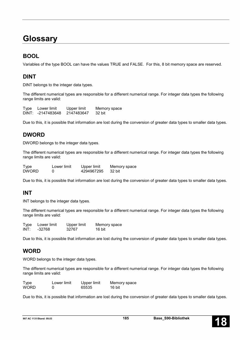
907 AC 1131/Stand: 09.03 185 Base_S90-Bibliothek 18
Glossary
BOOLVariables of the type BOOL can have the values TRUE and FALSE. For this, 8 bit memory space are reserved.
DINTDINT belongs to the integer data types.
The different numerical types are responsible for a different numerical range. For integer data types the followingrange limits are valid:
Type Lower limit Upper limit Memory spaceDINT: -2147483648 2147483647 32 bit
Due to this, it is possible that information are lost during the conversion of greater data types to smaller data types.
DWORDDWORD belongs to the integer data types.
The different numerical types are responsible for a different numerical range. For integer data types the followingrange limits are valid:
Type Lower limit Upper limit Memory spaceDWORD 0 4294967295 32 bit
Due to this, it is possible that information are lost during the conversion of greater data types to smaller data types.
INTINT belongs to the integer data types.
The different numerical types are responsible for a different numerical range. For integer data types the followingrange limits are valid:
Type Lower limit Upper limit Memory spaceINT: -32768 32767 16 bit
Due to this, it is possible that information are lost during the conversion of greater data types to smaller data types.
WORDWORD belongs to the integer data types.
The different numerical types are responsible for a different numerical range. For integer data types the followingrange limits are valid:
Type Lower limit Upper limit Memory spaceWORD 0 65535 16 bit
Due to this, it is possible that information are lost during the conversion of greater data types to smaller data types.

Base_S90 Library 186 907 AC 1131/Stand: 09.0318
FunctionsFunctions are subroutines which have multiple input parameters and return exactly one result element. Thereturned result can be of an elementary or a derived data type. Due to this, a function may also return an array, astructure, an array of structures and so on.
For the same input parameters, functions always return the same result (they do not have an internal memory).
Therefore, the following rules can derived:
• Within functions, global variables can neither be read nor written.• Within functions, it is not allowed to read or write absolute operands.• Within functions, it is not allowed to call function blocks.
Function blocksFunction blocks are subroutines which can have as much inputs, outputs and internal variables as required. Theyare called by a program or by another function block.
As they can be used several times (with different data records), function blocks (code and interface) can beconsidered as type. When assigning an individual data record (declaration) to the function block, a function blockinstance is generated.
In contrast to functions, function blocks can contain statically local data which are saved from one call to the next.This allows for example to realize counters which may not forget their counter value. I.e. function blocks can havean internal memory.
Functions and function blocks differ in two essential points:
• A function block has multiple output parameters. A function has maximally one output parameter. Note that theoutput parameters of functions and function blocks differ syntactically.
• In contrast to a function, a function block can have an internal memory.
1. Function blocks with historical values (memory):
For function blocks with historical values it has to be observed that instance names may not be defined severaltimes if different data sets should be called.
Example:
Name TypeVRZ1 VRZVRZ2 VRZ. .. .
2. Function blocks without historical values (memory):
For function blocks without historical values only one instance has to be defined for the FB type. This instance canbe used for several calls of the FB (also with different I/O values).
Example:
Name TypeADDD1 ADDD (for all ADDD blocks used in the program). .. .butADDD1 ADDD (for all ADDD blocks used in the program)SUBD1 SUBD (for all SUBD blocks used in the program). .. .The instance name can be defined without any restrictions. The type is preset and identical to the function blockname.

907 AC 1131/Stand: 09.03 187 Base_S90-Bibliothek 18
Index
AADDD S90 11
ADDW S90 12
ADRWA S90 13
AMELD S90 16
AMELDD S90 18
ASV S90 20
AWM S90 21
BBase S90
ADDD 11
ADDW 12
ADRWA 13
AMELD 16
AMELDD 18
ASV 20
AWM 21
BCDDUAL 22
BCDDUALD 24
BEG 26
BEGD 27
BITSU 28
BMELD8 31
COMPARE 33
COPY 34
COS1 35
COUNTBD 37
COUNTBW 38
COUNTW 39
DIVD 43
DIVW 45
DMUX 46
DMUXD 48
DT1 50
DUALBCD 52
DUALBCDD 54
DW2W 56
DWAES 57
DWOL 58
DWOS 59
DWUMC 60
DWW 62
ESV 63
FIFOB 64
FIFOW 66
FKG 68
HLG 70
IDLB 74
IDLM 76
IDSB 78
IDSM 80
INITSB 82
INITSD 83
INITSW 84
INITVB 85
INITVW 87
INTK 89
LDT 93
LIFOB 95
LIFOW 97
LIZU 99
LZB 101
MAJ 102
MASKE 103
MASKED 104
MAZ 105
MAZD 106
MOA 107
MOK 108
MUL2N 109
MUL2ND 111
MULD 113

Base_S90 Library 188 907 AC 1131/Stand: 09.0318
MULDI 114
MULW 115
MUXR 116
MUXRD 118
NEGD 120
NEGW 121
PACK 122
PACKD 124
PDM 126
PI 128
PIDT1 132
PT1 137
SETBD 139
SETBW 140
SHIFTD 141
SHIFTW 144
SIN1 147
SUBD 149
SUBW 150
TESTBD 151
TESTBW 152
UHR 153
UNPACK 156
UNPACKD 158
USM 160
UST 161
USTD 162
USTR 163
USTRD 164
VGL3P 165
VGLEH 167
VGLUH 169
VRZ 171
VRZD 173
VVZ 175
W2WDW 176
WAES 177
WDEC 178
WDWW 180
WOL 181
WOS 182
WUMC 183
BCDDUAL S90 22
BCDDUALD S90 24
BEG S90 26
BEGD S90 27
BITSU S90 28
BMELD S90 31
CCOMPARE S90 33
COPY S90 34
COS1 S90 35
COUNTBD S90 37
COUNTBW S90 38
COUNTW S90 39
DDIVD S90 43
DIVW S90 45
DMUX S90 46
DMUXD S90 48
DT1 S90 50
DUALBCD S90 52
DUALBCDD S90 54
DW2W S90 56
DWAES S90 57
DWOL S90 58
DWOS S90 59
DWUMC S90 60
DWW S90 62
EESV S90 63
FFIFOB S90 64
FIFOW S90 66
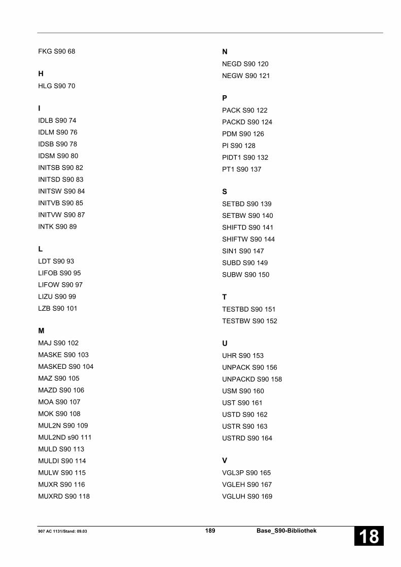
907 AC 1131/Stand: 09.03 189 Base_S90-Bibliothek 18
FKG S90 68
HHLG S90 70
IIDLB S90 74
IDLM S90 76
IDSB S90 78
IDSM S90 80
INITSB S90 82
INITSD S90 83
INITSW S90 84
INITVB S90 85
INITVW S90 87
INTK S90 89
LLDT S90 93
LIFOB S90 95
LIFOW S90 97
LIZU S90 99
LZB S90 101
MMAJ S90 102
MASKE S90 103
MASKED S90 104
MAZ S90 105
MAZD S90 106
MOA S90 107
MOK S90 108
MUL2N S90 109
MUL2ND s90 111
MULD S90 113
MULDI S90 114
MULW S90 115
MUXR S90 116
MUXRD S90 118
NNEGD S90 120
NEGW S90 121
PPACK S90 122
PACKD S90 124
PDM S90 126
PI S90 128
PIDT1 S90 132
PT1 S90 137
SSETBD S90 139
SETBW S90 140
SHIFTD S90 141
SHIFTW S90 144
SIN1 S90 147
SUBD S90 149
SUBW S90 150
TTESTBD S90 151
TESTBW S90 152
UUHR S90 153
UNPACK S90 156
UNPACKD S90 158
USM S90 160
UST S90 161
USTD S90 162
USTR S90 163
USTRD S90 164
VVGL3P S90 165
VGLEH S90 167
VGLUH S90 169
Base_S90 Library 190 907 AC 1131/Stand: 09.0318
VRZ S90 171
VRZD S90 173
VVZ S90 175
WW2WDW S90 176
WAES S90 177
WDEC S90 178
WDWW S90 180
WOL S90 181
WOS S90 182
WUMC S90 183

Software Description Advant Controller 31Intelligent DecentralizedAutomation System
RCOM/RCOM+Function Block Library90 Series
RCOM90 Series


907 AC 1131/Issued: 06.02 1 RCOM_S90 Library 18
Contents
RCOM library 21.1 CONSIDERABLE CHANGES IN RCOM LIBRARY RCOM BIB
COMPARED TO CE LIBRARY 907 KP 90 .................................. 2Function blocks: .................................. 21.2 PARAMETERS .................................. 21.3 NOTE ON BLOCK DATA .................................. 2
Overview of blocks listed alphabetically according to their call names 3SET CLOCK CLOCK ..................... 4COLD START COLDST ................... 6DIAL COMMUNICATION PARTNER DIAL.......................... 8HANG UP PHONE HANGUP ................ 10NORMALIZATION NORMAL ................ 12CARRY OUT EVENT POLL POLL....................... 14INITIALIZE 07 KP 90 R202 RCOM..................... 16INITIALIZE 07 KP 90 R202 RCOM_PL .............. 20READ DATA FROM RCOM SLAVE READ...................... 24PROVIDE DATA FOR READ JOB READ_S ................. 26RECEIVE DATA FROM RCOM PARTNER RECV...................... 28RCOM SYSTEM SERVICES SYS_S .................... 30SEND DATA TO RCOM PARTNER TRANSM................. 32WARM START WARMST................ 34
Glossary 37
Index 39

RCOM LIBRARY
RCOM_S90 Library 2 907 AC 1131/Issued: 06.0218
RCOM libraryThis chapter contains the description of the blockswhich are available for project engineering with the07 KP 90 R202.
1.1 CONSIDERABLE CHANGES INRCOM LIBRARY RCOM BIBCOMPARED TO CE LIBRARY907 KP 90
All blocks were converted to function blocksaccording to the IEC norm. (The correspondingdefinition can be found in the programming softwaremanual).
In the RCOM library, all blocks for data remotetransfer using the 07 KP 90 coupler (function blocks)are included.
Note:
The blocks defined in the RCOM library cannot beused in simulation mode.
In order to use these blocks the RCOM library(RCOM_S90_V41.LIB) must be included in the librarywindow.
Function blocks:A main characteristic of the function blocks is, that aninstance has to be defined when calling them. In thiscase it has to be observed that instance names mustnot be defined several times.
Example:Name TypeREAD1 READREAD2 READ. .. .
The instance name can be defined without anyrestrictions. The type is preset and identical to thefunction block name.
1.2 PARAMETERSIn this section, the most important parameters whichare relevant for the RCOM blocks are brieflyexplained.
NETThis parameter is reserved for future couplerexpansions and must always be zero.
NODThis parameter indicates the target and sourceaddress of a job. The RCOM master has addresszero, the valid range for the slave addresses is1..254. For broadcast jobs (only system services)NOD must be 255.
IDTThis parameter contains the number of the datarecord which should be called with the block. Validrange for the parameter is 1 ... 255.
LENThis parameter indicates the length of the called datarecord. LEN must be even and the valid range is2 ... 16. For events LEN may be max. 14, because inaddition to the user data the timing mark istransmitted.
1.3 NOTE ON BLOCK DATA
Programming systemThe programming software 907 AC 1131 is requiredfor block usage.

OVERVIEW OF BLOCKS LISTED ALPHABETICALLY ACCORDING TO THEIR CALL NAMES
907 AC 1131/Issued: 06.02 3 RCOM_S90 Library 18
Overview of blocks listed alphabetically according to their call names
Used abbreviations:
FBmV … Function block with historical values
FBoV … Function block without historical values
F … Function
CE name Type Function Page
CLOCK FB Set clock 4
COLDST FB Cold start 6
DIAL FB Dial communication partner 8
HANGUP FB Hang up phone 10
NORMAL FB Normalization 12
POLL FB Perform event poll 14
RCOM FB Initialize 07 KP 90 R202 for RCOM protocol 16
RCOM_PL FB Initialize 07 KP 90 R202 for RCOM+ protocol 20
READ FB Read data from RCOM slave 24
READ_S FB Provide data for READ job 26
RECV FB Receive data from RCOM partner 28
SYS_S FB RCOM system services 30
TRANSM FB Send data to RCOM partner 32
WARMST FB Warm start 34

SET CLOCK CLOCK
RCOM_S90 Library 4 907 AC 1131/Issued: 06.0218
SET CLOCK CLOCKWith this block, the RCOM master sets his own clockand the clocks of the called slaves to a specified time.
The clocks are used to build timing marks during theevent-controlled transfer. Additional to this, the RCOMsystem time is available for the user at the RCOMblock.
Block typeFunction block
ParametersInstance CLOCK instance nameFREI BOOL FREI edge at this input sets the clocksNET INT always zeroNOD INT number of the called slaveStd INT time, hoursMinu INT time, minutesSek INT time, secondsRDY BOOL ready messageERR BOOL error outputERR_NR BOOL error number
DescriptionThe function block transmits a telegram which sets thetime in the called slave to the specified value. Themaster clock is set to the same value.
FREI BOOLA FALSE/TRUE edge at input FREI starts the clocksetting. Further edges are ignored until RDY hasbecome “TRUE”.
NET INTMust always be zero.
NOD INTNumber of the slave. In order to set all slaves to thesame time, here should be entered 255 (all slaves arecalled).
Std INTTime, hours.
Minu INTTime, minutes.
Sek INTTime, seconds.
RDY BOOLOutput RDY indicates that the clock setting has beencompleted. This output has always to be consideredtogether with the output ERR. The following applies:
RDY = TRUE and ERR = FALSE: The clocks havebeen set successfully.
RDY = TRUE and ERR = TRUE: While setting theclocks an error occurred. In this case, the errormessage at output ERR_NR can be evaluated.
After one attempt, a falling edge at input FREI sets theoutputs RDY, ERR and ERR_NR to zero.
If the clock setting has not yet been completed (RDY =FALSE) after a FALSE/TRUE edge at input FREI, anew FALSE/TRUE edge at input FREI is ignored.

SET CLOCK CLOCK
907 AC 1131/Issued: 06.02 5 RCOM_S90 Library 18
ERR BOOLOutput ERR indicates whether an error occurred whilesetting the clock. Output ERR has always to beconsidered together with the output RDY.
If an error occurred, RDY = TRUE and ERR = TRUEare set. The error type can be evaluated using the errornumber at output ERR_NR.
ERR_NR INTAt output ERR_NR an error number is output. Thisoutput has always to be considered together with theoutputs RDY and ERR.
The error numbers are described in detail in appendix“Error codes”.
Function call in ILCAL CLOCK1(FREI := FREI, NET := NET,
NOD := NOD, Std := STD, Minu := MINU,Sek := SEK)
LD CLOCK1.ERRST ERRLD CLOCK1.ERR_NRST ERR_NRLD CLOCK1.RDYST RDY
Note: In IL, the function call has to be performed inone line.
Function call in STCLOCK1(FREI := FREI, NET := NET,NOD := NOD, Std := STD, Minu := MINU,Sek := SEK);ERR:=CLOCK1.ERR;ERR_NR:=CLOCK1.ERR_NR;RDY:=CLOCK1.RDY;

COLD START COLDST
RCOM_S90 Library 6 907 AC 1131/Issued: 06.0218
COLD START COLDSTWith this block, the RCOM master carries out a coldstart. It can either start all slaves or one individualslave.
The slave is partially reinitialized after the cold start.
Block typeFunction block
ParametersInstance COLDST instance nameFREI BOOL FALSE/TRUE edge at this input initiates a cold startNET INT always zeroNOD INT number of the slave to be startedRDY BOOL ready messageERR BOOL error outputERR_NR INT error number
DescriptionThe function block carries out a cold start at the calledslave. The slave coupler is partially reinitialized.
At the called slave the sequence marks are reset(RCOM specific protocol parameter) and thetransmission of data records is disabled. All entries inthe event queue are deleted and after this a cold startevent is generated.
After a cold start, always a normalization must occur.
The block has to be used for the initialization of theRCOM network, e.g. after the initialization07 KP 90 R202 at the master.
FREI BOOLA FREI edge at input FREI initiates a cold start. Furtheredges are ignored until RDY has become “TRUE”.
NET INTMust always be zero.
NOD INTNumber of the slave to be started. For NOD=255 allslaves are called.
RDY BOOLOutput RDY indicates that the cold start has beencompleted. This output has always to be consideredtogether with the output ERR. The following applies:
RDY = TRUE and ERR = FALSE: The cold start hasbeen terminated. The planned slaves have been reset.
RDY = TRUE and ERR = FALSE: An error occurredduring the cold start. In this case, the error message atoutput ERR_NR can be evaluated.
After a cold start, a falling edge at input FREI sets theoutputs RDY, ERR and ERR_NR to zero.
If the cold start has not yet been completed (RDY =FALSE) after a FALSE/TRUE edge at input FREI, anew FALSE/TRUE edge at input FREI is ignored.
ERR BOOLOutput ERR indicates whether an error occurred duringthe cold start. Output ERR has always to be consideredtogether with the output RDY.
If an error occurred during the cold start, RDY = TRUEand ERR = TRUE are set. The error type can beevaluated using the error number at output ERR_NR.

COLD START COLDST
907 AC 1131/Issued: 06.02 7 RCOM_S90 Library 18
ERR_NR INTAt output ERR_NR an error number is output. Thisoutput has always to be considered together with theoutputs RDY and ERR.
The error numbers are described in detail in appendix“Error codes”.
Function call in ILCAL COLDST1(FREI := FREI, NET := NET,
NOD := NOD)
LD COLDST1.ERRST ERRLD COLDST1.ERR_NRST ERR_NRLD COLDST1.RDYST RDY
Note: In IL, the function call has to be performed inone line.
Function call in STCOLDST1(FREI := FREI, NET := NET,NOD := NOD);ERR:=COLDST1.ERR;ERR_NR:=COLDST1.ERR_NR;RDY:=COLDST1.RDY;

DIAL COMMUNICATION PARTNER DIAL
RCOM_S90 Library 8 907 AC 1131/Issued: 06.0218
DIAL COMMUNICATION PARTNER DIALWith this block a RCOM subscriber can call anothersubscriber.
A master can call any slave. Using this block, a slavecan call the RCOM master to request event polling.
The block can only be used if the RCOM network isrealized with switched connections (Mdm=1 for RCOMblock).
Block typeFunction block
ParametersInstance DIAL instance nameFREI BOOL FALSE/TRUE edge at this input starts the dialling procedureNET INT always zeroNOD INT number of the slave to be calledRDY BOOL ready messageERR BOOL error outputERR_NR INT error number
DescriptionFor dial lines, the function block calls the specifiedsubscriber. In the RCOM master, the block must beused before transmitting system services or datarecords to a slave. Using this block, a slave can call themaster to request event polling.
The telephone line is terminated using the HANGUPblock after transmission is completed.
FREI BOOLA FALSE/TRUE edge at input FREI starts the diallingprocedure. Further edges are ignored until RDY hasbecome “TRUE”.
NET INTMust always be zero.
NOD INTNumber of the subscriber to be called. Here, the entryin the telephone list is specified which should be called.Example: NOD=5: The 5. entry in the telephone list iscalled.
RDY BOOLOutput RDY indicates that the dialling has beencompleted. This output has always to be consideredtogether with the output ERR. The following applies:
RDY = TRUE and ERR = FALSE: The telephone line isready for data transfer.
RDY = TRUE and ERR = TRUE: An error occurredduring the dialling procedure. In this case, the errormessage at output FeNR can be evaluated.
After a dialling operation, a falling edge at input FREIsets the outputs RDY, ERR and FeNR to zero.
If the dialling has not yet been completed (RDY =FALSE) after a FALSE/TRUE edge at input FREI, anew FALSE/TRUE edge at input FREI is ignored.
ERR BOOLOutput ERR indicates whether an error occurred duringthe dialling. Output ERR has always to be consideredtogether with the output RDY.
If an error occurred during the dialling, RDY = TRUEand ERR = TRUE are set. The error type can beevaluated using the error number at output FeNR.

DIAL COMMUNICATION PARTNER DIAL
907 AC 1131/Issued: 06.02 9 RCOM_S90 Library 18
ERR_NR INTAt output FeNR an error number is output. This outputhas always to be considered together with the outputsRDY and ERR.
The error numbers are described in detail in appendix“Error codes”.
Function call in ILCAL DIAL1(FREI := FREI, NET := NET,
NOD := NOD)
LD DIAL1.ERRST ERRLD DIAL1.ERR_NRST ERR_NRLD DIAL1.RDYST RDY
Note: In IL, the function call has to be performed inone line.
Function call in STDIAL1(FREI := FREI, NET := NET,NOD := NOD);ERR:=DIAL1.ERR;ERR_NR:=DIAL1.ERR_NR;RDY:=DIAL1.RDY;

HANG UP PHONE HANGUP
RCOM_S90 Library 10 907 AC 1131/Issued: 06.0218
HANG UP PHONE HANGUPWith this block, the master can hang up the phone in aRCOM network with switched connections.
The block cannot be used until all jobs for a slave areprocessed completely.
The block can only be used if the RCOM network isrealized with switched connections(Mdm=1 for RCOM block).
Block typeFunction block
ParametersInstance HANGUP instance nameFREI BOOL FALSE/TRUE edge at this input hangs up the phoneNET INT always zeroNOD INT number of the slaveRDY BOOL ready messageERR BOOL error outputERR_NR INT error number
DescriptionFor dial lines, the function block hangs up the phone.
The block must be used to terminate a connection aftertransmitting data records to or from a slave.
FREI BOOLA FALSE/TRUE edge at input FREI starts the hangingup operation. Further edges are ignored until RDY hasbecome “TRUE”.
NET INTMust always be zero.
NOD INTNumber of the slave which has been called before. The07 KP 90 R202 ignores this parameter, it is alwayshang up.
RDY BOOLOutput RDY indicates that the hanging up operationhas been completed. This output has always to beconsidered together with the output ERR. The followingapplies:
RDY = TRUE and ERR = FALSE: The telephone linewas successful interrupted.
RDY = TRUE and ERR = TRUE: An error occurredduring the hang up operation. In this case, the errormessage at output ERR_NR can be evaluated.
After the hang up operation, a falling edge at inputFREI sets the outputs RDY, ERR and ERR_NR to zero.
If the hang up has not yet been completed (RDY =FALSE) after a FALSE/TRUE edge at input FREI, anew FALSE/TRUE edge at input FREI is ignored.
ERR BOOLOutput ERR indicates whether an error occurred duringthe hang up operation. Output ERR has always to beconsidered together with the output RDY.
If an error occurred during the hang up operation,RDY = TRUE and ERR = TRUE are set. The error typecan be evaluated using the error number at outputERR_NR.
ERR_NR INTAt output ERR_NR an error number is output. Thisoutput has always to be considered together with theoutputs RDY and ERR.
The error numbers are described in detail in appendix“Error codes”.

HANG UP PHONE HANGUP
907 AC 1131/Issued: 06.02 11 RCOM_S90 Library 18
Function call in ILCAL HANGUP1(FREI := FREI, NET := NET,
NOD := NOD)
LD HANGUP1.ERRST ERRLD HANGUP1.ERR_NRST ERR_NRLD HANGUP1.RDYST RDY
Note: In IL, the function call has to be performed inone line.
Function call in STHANGUP1(FREI := FREI, NET := NET,NOD := NOD);ERR:=HANGUP1.ERR;ERR_NR:=HANGUP1.ERR_NR;RDY:=HANGUP1.RDY;

NORMALIZATION NORMAL
RCOM_S90 Library 12 907 AC 1131/Issued: 06.0218
NORMALIZATION NORMALWith this block, the master enables the data recordtransfer.
A normalization must be performed after a cold orwarm start.
Block typeFunction block
ParametersInstance NORMAL instance nameFREI BOOL FALSE/TRUE edge at this input initiates a normalizationNET INT always zeroNOD INT number of the slave to be normalizedRDY BOOL ready messageERR BOOL error outputERR_NR INT error number
DescriptionThe function block carries out a normalization at thecalled slave. Due to this the data record transfer isenabled.
Before the data record transfer, after the switch-on andafter a cold or warm start, the block has to beprocessed once.
FREI BOOLA FALSE/TRUE edge at input FREI starts thenormalization. Further edges are ignored until RDY hasbecome “TRUE”.
NET INTMust always be zero.
NOD INTNumber of the slave to be normalized. For NOD=255all slaves are called.
RDY BOOLOutput RDY indicates that the normalization has beencompleted. This output has always to be consideredtogether with the output ERR. The following applies:
RDY = TRUE and ERR = FALSE: The normalizationhas been completed.
RDY = TRUE and ERR = TRUE: An error occurredduring the normalization. In this case, the errormessage at output ERR_NR can be evaluated.
After a normalization, a falling edge at input FREI setsthe outputs RDY, ERR and ERR_NR to zero.
If the normalization has not yet been completed (RDY =FALSE) after a FALSE/TRUE edge at input FREI, anew FALSE/TRUE edge at input FREI is ignored.
ERR BOOLOutput ERR indicates whether an error occurred duringthe normalization. Output ERR has always to beconsidered together with the output RDY.
If an error occurred during the normalization, RDY =TRUE and ERR = TRUE are set. The type of error canbe evaluated using the error number at outputERR_NR.
ERR_NR INTAt output ERR_NR an error number is output. Thisoutput has always to be considered together with theoutputs RDY and ERR.
The error numbers are described in detail in appendix“Error codes”.

NORMALIZATION NORMAL
907 AC 1131/Issued: 06.02 13 RCOM_S90 Library 18
Function call in ILCAL NORMAL1(FREI := FREI, NET := NET,
NOD := NOD)
LD NORMAL1.ERRST ERRLD NORMAL1.ERR_NRST ERR_NRLD NORMAL1.RDYST RDY
Note: In IL, the function call has to be performed inone line.
Function call in STNORMAL1(FREI := FREI, NET := NET,NOD := NOD);ERR:=NORMAL1.ERR;ERR_NR:=NORMAL1.ERR_NR;RDY:=NORMAL1.RDY;

CARRY OUT EVENT POLL POLL
RCOM_S90 Library 14 907 AC 1131/Issued: 06.0218
CARRY OUT EVENT POLL POLLWith this block the master performs an event poll on aslave.
If the slave sends back data records, these appear in acorrespondingly configured RECV block in the master.
The block polls the slave until the number MaxP (blockRCOM) is reached or the slave has no further datarecords.
Block typeFunction block
ParametersInstance POLL instance nameFREI BOOL FREI edge at this input initiates event pollNET INT always zeroNOD INT number of the slave to be polledRDY BOOL ready messageERR BOOL error outputERR_NR INT error number
DescriptionThe block performs an event poll at the called slave,i.e. the slave is asked whether it wants to transmit datarecords to the master.
The slave data records appear at a correspondinglyconfigured RECV block in the master.
FREI BOOLA FALSE/TRUE edge at input FREI starts the eventpoll. Further edges are ignored until RDY has become“TRUE”.
NET INTMust always be zero.
NOD INTNumber of the slave to be polled (1...254).
RDY BOOLOutput RDY indicates that the poll process has beencompleted. This output has always to be consideredtogether with the output ERR. The following applies:
RDY = TRUE and ERR = FALSE: The poll event hasbeen completed.
RDY = TRUE and ERR = TRUE: An error occurredduring the polling. In this case, the error message atoutput ERR_NR can be evaluated.
After a poll, a falling edge at input FREI sets theoutputs RDY, ERR and ERR_NR to zero.
If the event poll has not yet been completed (RDY =FALSE) after a FALSE/TRUE edge at input FREI, anew FALSE/TRUE edge at input FREI is ignored.
ERR BOOLOutput ERR indicates whether an error occurred duringthe polling. Output ERR has always to be consideredtogether with the output RDY.
If an error occurred during the polling, RDY = TRUEand ERR = TRUE are set. The type of error can beevaluated using the error number at output ERR_NR.
ERR_NR INTAt output ERR_NR an error number is output. Thisoutput has always to be considered together with theoutputs RDY and ERR.
The error numbers are described in detail in appendix“Error codes”.

CARRY OUT EVENT POLL POLL
907 AC 1131/Issued: 06.02 15 RCOM_S90 Library 18
Function call in ILCAL POLL1(FREI := FREI, NET := NET,
NOD := NOD)
LD POLL1.ERRST ERRLD POLL1.ERR_NRST ERR_NRLD POLL1.RDYST RDY
Note: In IL, the function call has to be performed inone line.
Function call in STPOLL1(FREI := FREI, NET := NET,NOD := NOD);ERR:=POLL1.ERR;ERR_NR:=POLL1.ERR_NR;RDY:=POLL1.RDY;

INITIALIZE 07 KP 90 R202 RCOM
RCOM_S90 Library 16 907 AC 1131/Issued: 06.0218
INITIALIZE 07 KP 90 R202 RCOMThis block is used for initializing the 07 KP 90 R202. Allnecessary network parameters are defined here. At theRCOM master and every RCOM slave, the intializationmust be performed before starting other blocks.
The block enters the network parameters and thenstarts the coupler initialization.
The block also supplies the 07 KP 90 R202 cyclecounter value (life identifier) and the RCOM systemtime until input FREI is “TRUE”. Additionally, thecurrent event queue level (i.e. the number of datarecords which are still queued) is displayed at outputEvtP of RCOM slaves.
Block typeFunction block
ParametersInstance RCOM instance nameFREI BOOL enabling of the block processing with FALSE/TRUE edgeNET INT always 0NOD INT RCOM master: 0, RCOM slave: number of the slaveBaud INT baud rate for RCOM interfacePari INT parity: 0: none,1: odd, 2: evenDupl INT 0: half duplex, 1: full duplexTLS INT time for carrier stabilizationCdly INT waiting time for carrier stopCTO INT character delay timeTAT INT reaction time for responseMdm INT modem typeRetr INT number of repetitive attemptsMaxP INT maximum number of event polls for a slave in a cycleNoPr INT number of preambles in the protocolDbg INT debug stepRDY BOOL ready messageERR BOOL error outputERR_NR INT error numberZykl INT cycle counter valueNT BOOL new time availableStd INT time, hoursMinu INT time, minutesSek INT time, secondsEvtP INT number of events in the event queue

INITIALIZE 07 KP 90 R202 RCOM
907 AC 1131/Issued: 06.02 17 RCOM_S90 Library 18
DescriptionThe block is used to initialize the 07 KP 90 R202. Thenecessary network parameters are set and theinitialization is started.
After the block has been started, the input parametersmust not be changed. Therefore the parameters shouldbe defined as constants.
With a FALSE/TRUE edge at input FREI theinitialization is performed once.
If the initialization has not yet been completed, furtherFALSE/TRUE edges at input FREI are ignored. Afterthe intitialization has been completed, the outputs RDY,ERR and ERR_NR are set.
The initialization was successful if RDY = TRUE andERR = FALSE. For RDY = TRUE and ERR = TRUE, anerror occurred. The type of error can be determinedusing the output ERR_NR.
After initialization, the outputs ERR, ERR_NR, Zyk, NT,Std, Min, Sek and EvtP are updated in every PLCcycle, if input FREI is “TRUE”. Therefore the 07 KP 90R202 reports the cycle counter value or error reports tothe PLC. Due to this, input FREI should always remain“TRUE” during running operation of the coupler, exceptwhen the coupler has to be reinitialized with newparameters.
ERR and ERR_NR are reset with a falling edge at inputFREI.
Zyk contains the current cycle counter value in the07 KP 90 R202.The outputs NT, Std, Min and Sekcontain the RCOM system time which can also be usedin the PLC program. Time starts at switch-on with00:00.00. If the command ‘set clock’ is received, thetime is set to the new value, NT then is set for approx.5 seconds (e.g. suitable for setting a real time clock).
For a RCOM slave, output EvtP contains the number ofevents which are saved in the event queue. For theRCOM master, this output is always zero.
Note: For the RCOM parameters some english namesin brackets are listed. They correspond to the masterpiece names in the ‘data set for line characteristics’.
FREI BOOLWith a FALSE/TRUE edge at input FREI theinitialization is started. With this FALSE/TRUE edge,the outputs RDY, ERR and ERR_NR are also set tozero. If the writing operation has not yet beencompleted (RDY = FALSE), a further FALSE/TRUEedge at input FREI is ignored. During FREI is set toone, the outputs ERR, ERR_NR and Zyk are updatedconstantly.
NET INTMust always be zero.
NOD INTIndicates the RCOM network address.
0: RCOM master
otherwise: slave number
A RCOM network can contain only one master.
Baud INT(bitrate) transmission rate, possible values are300, 600, 1200, 2400, 4800, 9600, 19.200.
Pari INTparity, possible values:
0 -> no parity
1 -> odd parity
2 -> even parity
Dupl INT(duplex)
0 -> half duplex
1 -> full duplex
This parameter depends on the used transmissionmedium. Refer to chapter ‘Planning’.
TLS INT(line stab. time) Number of characters used as waitingtime before sending a telegram (e.g. for carrierstabilization). Recommended values for 1200 baud: 3characters for dial lines, 2 characters for multidroplines. Refer to section ‘Hardware Handshake’.
CDly INT(carrier delay) Number of characters used as waitingtime after sending a telegram. Recommended valuesfor 1200 baud: 2 characters for dial lines, 0 charactersfor multidrop lines. Refer to section ‘HardwareHandshake’.
CTO INT(char. timeout) character delay time. Number ofcharacters which are waited, before a telegram isrejected as interrupted. Recommended value: 30.

INITIALIZE 07 KP 90 R202 RCOM
RCOM_S90 Library 18 907 AC 1131/Issued: 06.0218
TAT INT(turnaround time) Maximum time in msec for which theRCOM master waits for a slave response (maximumslave reaction time). Must always be specified greaterthan 2000. Recommended value: 4000.
Mdm INT(type of modem) Used modem. The following modemtypes are permissible:
0: direct connection or fixed line modem
1: Hayes compatible dial modem
2: installed RS485 interface
3: modem 23 WT 90 half duplex
Retr INT(retransmissions) Maximum number of repetitiveattempts before the line is considered as interrupted.Recommended value: 2.
MaxP INT(max no poll) If during the event poll an event is sent bythe slave, the master can perform further event polls.This parameter specifies the maximum numbers ofevent polls which are carried out.Recommended value: 3.
NoPr INT(no of preambles) Number of preambles in the RCOMprotocol. Recommended values: 1 for multidrop, 3 fordial lines.
RDY BOOLThe output RDY indicates that the initialization hasbeen completed. This output has always to beconsidered together with the output ERR. The followingapplies:
RDY = TRUE and ERR = FALSE: Initializationhas been completed. The parameters were read andaccepted by the 07 KP 90.
RDY = TRUE and ERR = TRUE: An erroroccurred during the initialization. In this case, the errormessage at output ERR_NR can be evaluated.
After a initilization, a falling edge at input FREI sets theoutputs RDY, ERR and ERR_NR to zero.
If the initialization has not yet been completed (RDY =FALSE) after a FALSE/TRUE edge at input FREI, anew FALSE/TRUE edge at input FREI is ignored.
ERR BOOLOutput ERR indicates whether an error occurred duringthe initialization. Output ERR has always to beconsidered together with the output RDY.
If an error occurred, RDY = TRUE and ERR = TRUEare set. The error type can be evaluated using the errornumber at output ERR_NR.
ERR is also set if FREI is still “TRUE” and the 07 KP 90R202 reports a fatal error.
ERR_NR INTAt output ERR_NR an error number is output. Thisoutput has always to be considered together with theoutputs RDY and ERR.
ERR_NR can also report an error in running operation,if input FREI is “TRUE”.
The error numbers are described in detail in appendix“Error codes”.
Zykl INTAt output Zykl, the current value of the 07 KP 90 R202cycle counter is updated as long as FREI is “TRUE”.The cycle counter should be used for monitoring the 07KP 90 R202 (life identifier).
NT BOOLOutput NT is set for approx. 5 seconds to “TRUE” if anew RCOM time was set (with block CLOCK). It can beused for setting a real time clock with the current valuesof Std, Min and Sek.
Std INTThe output contains the RCOM system time in hours.The master can set the time using the CLOCK block.
Minu INTThe output contains the RCOM system time in minutes.
Sek INTThe output contains the RCOM system time inseconds.
EvtP INTFor a RCOM slave, the output contains the number ofevents which are saved in the event queue. For theRCOM master, this output is always zero.
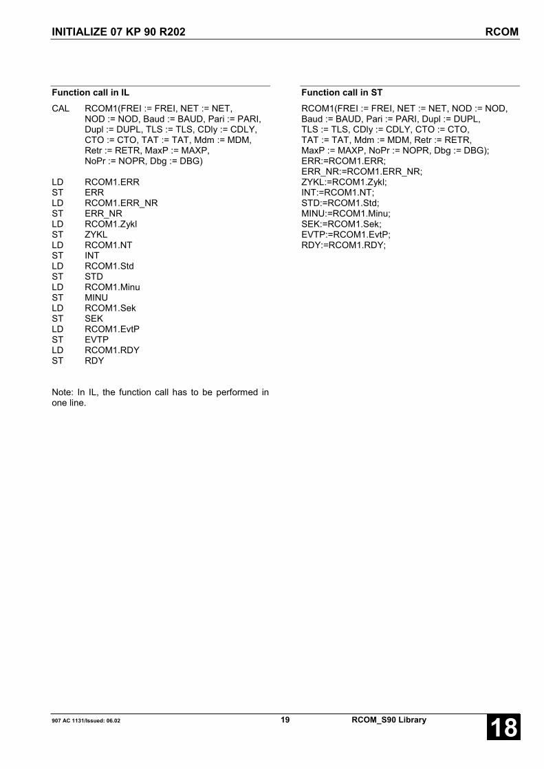
INITIALIZE 07 KP 90 R202 RCOM
907 AC 1131/Issued: 06.02 19 RCOM_S90 Library 18
Function call in ILCAL RCOM1(FREI := FREI, NET := NET,
NOD := NOD, Baud := BAUD, Pari := PARI,Dupl := DUPL, TLS := TLS, CDly := CDLY,CTO := CTO, TAT := TAT, Mdm := MDM,Retr := RETR, MaxP := MAXP,NoPr := NOPR, Dbg := DBG)
LD RCOM1.ERRST ERRLD RCOM1.ERR_NRST ERR_NRLD RCOM1.ZyklST ZYKLLD RCOM1.NTST INTLD RCOM1.StdST STDLD RCOM1.MinuST MINULD RCOM1.SekST SEKLD RCOM1.EvtPST EVTPLD RCOM1.RDYST RDY
Note: In IL, the function call has to be performed inone line.
Function call in STRCOM1(FREI := FREI, NET := NET, NOD := NOD,Baud := BAUD, Pari := PARI, Dupl := DUPL,TLS := TLS, CDly := CDLY, CTO := CTO,TAT := TAT, Mdm := MDM, Retr := RETR,MaxP := MAXP, NoPr := NOPR, Dbg := DBG);ERR:=RCOM1.ERR;ERR_NR:=RCOM1.ERR_NR;ZYKL:=RCOM1.Zykl;INT:=RCOM1.NT;STD:=RCOM1.Std;MINU:=RCOM1.Minu;SEK:=RCOM1.Sek;EVTP:=RCOM1.EvtP;RDY:=RCOM1.RDY;

INITIALIZE 07 KP 90 R202 RCOM_PL
RCOM_S90 Library 20 907 AC 1131/Issued: 06.0218
INITIALIZE 07 KP 90 R202 RCOM_PLThis block is used for initializing the 07 KP 90 R202. Allnecessary network parameters are defined here. At theRCOM master and every RCOM slave, the intializationmust be performed before starting other blocks.
The block enters the network parameters and thenstarts the coupler initialization.
The block also supplies the 07 KP 90 R202 cyclecounter value (life identifier) and the RCOM systemtime until input FREI is “TRUE”. Additionally, thecurrent event queue level (i.e. the number of datarecords which are still queued) is displayed at outputEvtP of RCOM slaves.
The RCOM+ block can be used with the communicationmodule 07 KP 90 beginning with index b.
Block typeFunction block
ParametersInstance RCOM_PL instance nameFREI BOOL enabling of the block processing with FALSE/TRUE edgeNET INT always 0NOD INT RCOM master: 0, RCOM slave: number of the slaveBaud INT baud rate for RCOM interfacePari INT parity: 0: none,1: odd, 2: evenDupl INT 0: half duplex, 1: full duplexTLS INT time for carrier stabilizationCdly INT waiting time for carrier stopCTO INT character delay timeTAT INT reaction time for responseMdm INT modem typeRetr INT number of repetitive attemptsMaxP INT maximum number of event polls for a slave in a cycleNoPr INT number of preambles in the protocolDbg INT debug stepRDY BOOL ready messageERR BOOL error outputERR_NR INT error numberZykl INT cycle counter valueNT BOOL new time availableStd INT time, hoursMinu INT time, minutesSek INT time, secondsEvtP INT number of events in the event queue

INITIALIZE 07 KP 90 R202 RCOM_PL
907 AC 1131/Issued: 06.02 21 RCOM_S90 Library 18
DescriptionIn the RCOM+ block the internal variable RCOM_typis set to 1. At RCOM, RCOM_typ = 0.
Note: All block parameters (except CTO) are identicalto the RCOM block parameters.
Switching between RCOM and RCOM+Switching between RCOM and RCOM+ is performedby planning the blocks RCOM or RCOM+.
Setting the “intermission” for RCOM+
The “intermission” is set with the CTO parameter(character timeout) at the RCOM+ block. The CTOparameter is transferred as a number of characters.In such a way, the following calculation results forintermission duration:
time [ms] =
CTO [char] D 10 [bit/char] D 1000 [ms/s] / baud [bit/s]
The minimum ascertainable time in the RCOMcoupler is 10 ms. Therefore the following calculationfor the parameter CTO results:
CTO [char] =
time [ms] D baud [bit/s] / 10 [bit/char] / 1000 [ms/s]
Example:
baud =
1200 CTO = 30 * 1200/10000 = 3,6 � 4
2400 CTO = 30 * 2400/10000 = 7,2 � 8
9600 CTO = 30 * 9600/10000 = 28,8� 29
19200 CTO = 30 * 19200/10000 = 57,6� 58
Representation in the operatorWhen showing the RCOM parameters in the terminal(enter rcom<CR>), the parameters RCOM_type andDIGI_time are displayed.
rcom typ: 1 - RCOM+ / 0 - RCOM
digi time: 0 - Standard
Error messagesWhile checking the parameters transferred with theRCOM or RCOM+ blocks, the parametersRCOM_typ and DIGI_time are checked.
If the parameter RCOM_typ is <0 or >1, an error isreported:
E_NET_PARAM + 20 2014hex = 8212dez
Initialization error: wrong RCOM type
If the parameter DIGI_time for RCOM+ is <0, thefollowing error is reported:
E_NET_PARAM + 21 2015hex = 8213dez
Initialization error: wrong value for DIGI_time
Transmission delay using the DIGI_timeparameterUsing the DIGI_time parameter, the transmission canbe delayed, i.e. it is waited briefly between theindividual telegram characters. Internal, the waitingtime is realized using a “FOR loop with a variablenumber of runs”.
for (i=0; i<DIGI_time; i++);
The following times and delays resulted during thetest:
t_char - time for 1 character [ms]
nt - delay [ms]
Using COMWATCH, the times have been measuredfor the direct connection of a T200 / 07 KP 64(MASTER) and a AC31 / 07 KT 93 / 07 KP 90 R2with pari=1 (11 bit frame).
The minimum time for 1 character can be calculatedwith:
t [ms] = 11 [bit/s] * 1000 [ms/s] / baud [bit/s]
for: 1200baud � t = 11 * 1000/1200 = 9,167 ms
2400 baud � t = 11 * 1000/2400 = 4,583 ms
9600 baud � t = 11 * 1000/9600 = 1,146 ms
19200 baud � t = 11 * 1000/19200 = 0,573 ms
Referring to the table, the delay does not have aneffect until the minimum time for a character isreached.
Changing the DIGI_time parameter by 50 causes adelay of approx. 0,5-0,6 ms.

INITIALIZE 07 KP 90 R202 RCOM_PL
RCOM_S90 Library 22 907 AC 1131/Issued: 06.0218
19200 baud 9600 baud 2400 baudt_char nt t_char nt t_char nt
DIGI_time [ms] [ms] [ms] [ms] [ms] [ms]0 0.6 0.0 1.2 0.0 4.5 0.050 0.7 0.1 1.2 0.0 4.5 0.0100 1.2 0.6 1.3 0.1 4.5 0.0150 1.8 1.2 1.8 0.6 4.5 0.0200 2.3 1.7 2.4 1.2 4.5 0.0250 2.9 2.3 2.9 1.7 4.6 0.1300 3.4 2.8 3.4 2.2 4.6 0.1350 4.0 3.4 4.0 2.8 4.6 0.1400 4.6 4.0 4.5 3.3 4.6 0.1450 5.1 4.5 5.1 3.9 5.1 0.6500 5.7 5.1 5.7 4.5 5.6 1.1550 6.2 5.6 6.2 5.0 6.2 1.7600 6.7 6.1 6.8 5.6 6.8 2.3650 7.3 6.7 7.3 6.1 7.4 2.9700 7.8 7.2 7.8 6.6 7.9 3.4750 8.4 7.8 8.4 7.2 8.4 3.9800 8.9 8.3 8.9 7.7 9.0 4.5850 9.5 8.9 9.5 8.3 9.5 5.0900 10.1 9.5 10.1 8.9 10.1 5.6950 10.6 10.1 10.6 9.4 10.6 6.11000 11.2 10.6 11.2 10.0 11.2 6.7
With the primary formula for the calculation of a FORloop time duration it was assumed, that one run takesapprox. 20 processor pulses. The measuring resultsshow, that one run takes approx. 180 processor pulses.For a 16 MHz processor a processor pulse takes 62,5ns. Therefore one run takes approx. 62,5 D 180 =11250 ns (0,01125 ms).
Transfer of the DIGI_time parameter WOSAt the Advant Controller 31 the transfer is performedwith the WOS block (write word).
At input E1 the corresponding DIGI_time is specified.
The address specifications must be observed under allcircumstances. In the PLC program, the WOS blockhas to be used directly after the RCOM+ block.
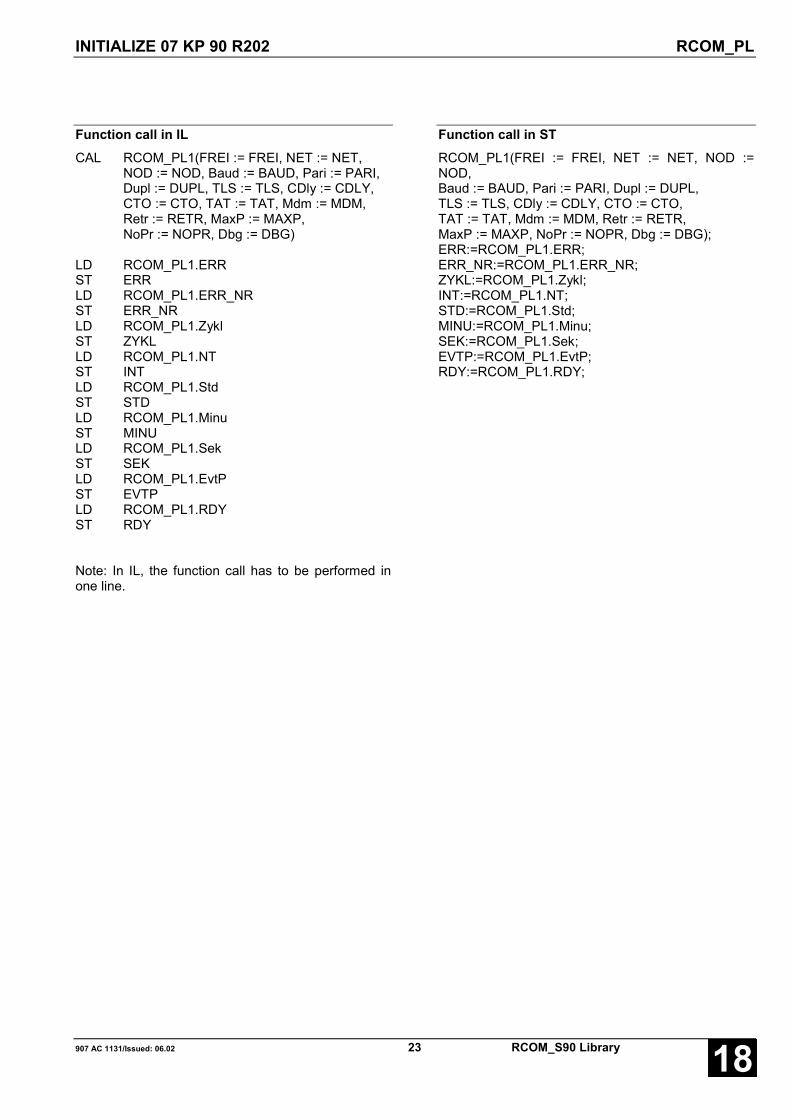
INITIALIZE 07 KP 90 R202 RCOM_PL
907 AC 1131/Issued: 06.02 23 RCOM_S90 Library 18
Function call in ILCAL RCOM_PL1(FREI := FREI, NET := NET,
NOD := NOD, Baud := BAUD, Pari := PARI,Dupl := DUPL, TLS := TLS, CDly := CDLY,CTO := CTO, TAT := TAT, Mdm := MDM,Retr := RETR, MaxP := MAXP,NoPr := NOPR, Dbg := DBG)
LD RCOM_PL1.ERRST ERRLD RCOM_PL1.ERR_NRST ERR_NRLD RCOM_PL1.ZyklST ZYKLLD RCOM_PL1.NTST INTLD RCOM_PL1.StdST STDLD RCOM_PL1.MinuST MINULD RCOM_PL1.SekST SEKLD RCOM_PL1.EvtPST EVTPLD RCOM_PL1.RDYST RDY
Note: In IL, the function call has to be performed inone line.
Function call in STRCOM_PL1(FREI := FREI, NET := NET, NOD :=NOD,Baud := BAUD, Pari := PARI, Dupl := DUPL,TLS := TLS, CDly := CDLY, CTO := CTO,TAT := TAT, Mdm := MDM, Retr := RETR,MaxP := MAXP, NoPr := NOPR, Dbg := DBG);ERR:=RCOM_PL1.ERR;ERR_NR:=RCOM_PL1.ERR_NR;ZYKL:=RCOM_PL1.Zykl;INT:=RCOM_PL1.NT;STD:=RCOM_PL1.Std;MINU:=RCOM_PL1.Minu;SEK:=RCOM_PL1.Sek;EVTP:=RCOM_PL1.EvtP;RDY:=RCOM_PL1.RDY;

READ DATA FROM RCOM SLAVE READ
RCOM_S90 Library 24 907 AC 1131/Issued: 06.0218
READ DATA FROM RCOM SLAVE READWith this block it is possible to read data records from aRCOM slave. The block can only be used by a master;slaves can not read data from the master.
The READ_S block must be implemented in the calledslave.
Block typeFunction block
ParametersInstance READ instance nameFREI BOOL enabling of the block processing with FALSE/TRUE edgeNET INT always zeroNOD INT number of the called RCOM slaveIDT INT number of the data record to be readLEN INT number of the words to be readAMW INT start flag of the flag area where the read words are storedRDY BOOL ready messageERR BOOL error outputERR_NR BOOL error number
DescriptionThe function block READ is used to read data from aRCOM slave. For reading, a READ job is sent to thecommunication partner via the 07 KP 90 R202communication module. As a result, the communicationpartner sends an acknowledgement including thedesired data.
The read data are stored in a flag area to be specified.
Before data can be transmitted using the READfunction block, the 07 KP 90 R202 communicationmodule must have been initialized (RCOM functionblock). Additionally, a normalization is necessary beforetransmitting.
If a job is started (FALSE/TRUE edge at input FREI),the data at the inputs NET, NOD, IDT, LEN and AMWmust not be changed until the job is completed (RDY =TRUE).
With a FALSE/TRUE edge at input FREI the readingoperation is performed once.
If the reading operation has not yet been completed,further FALSE/TRUE edges at input FREI are ignored.After the reading operation has been completed, theoutputs RDY, ERR and ERR_NR are set.
Using the inputs NET and NOD, it is specified whichRCOM subscriber should provide the data. IDT
specifies the data record number within this subscriber,LEN specifies the number of transmitted words.
The reading operation was successful, if RDY = TRUEand ERR = FALSE. For RDY = TRUE and ERR =TRUE, an error occurred. The error type can bedetermined using the output ERR_NR. RDY, ERR andERR_NR are reset with a falling edge at input FREI.
FREI BOOLWith a FALSE/TRUE edge at input FREI the readingoperation is performed once. With this FALSE/TRUEedge, the outputs RDY, ERR and ERR_NR are also setto zero. If the reading operation has not yet beencompleted (RDY = FALSE), a further FALSE/TRUEedge at input FREI is ignored.
NET INTMust always be zero.
NOD INTAt input NOD, the number of the called RCOMsubscriber is specified. Only slaves can be called(NOD=1...254).
READ DATA FROM RCOM SLAVE READ
907 AC 1131/Issued: 06.02 25 RCOM_S90 Library 18
IDT INTNumber of the data record to be read
LEN INTAt the input, the number of words to be read isspecified. The number must be even-numbered.
AMW INTAt input AMW, the first flag of the flag area is specifiedwhere the data should be stored.
RDY BOOLOutput RDY indicates that the reading operation hasbeen completed. This output has always to beconsidered together with the output ERR. The followingapplies:
RDY = TRUE and ERR = FALSE: The readingoperation has been completed. The variable areashave been read by the RCOM slave and transferred tothe data record.
RDY = TRUE and ERR = TRUE: An error occurredduring the reading operation. In this case, the errormessage at output ERR_NR can be evaluated. No datawere transferred to the data record.
After a reading operation, a falling edge at input FREIsets the outputs RDY, ERR and ERR_NR to zero.
If the reading operation has not yet been completed(RDY = FALSE) after a FALSE/TRUE edge at inputFREI, a new FALSE/TRUE edge at input FREI isignored.
ERR BOOLOutput ERR indicates whether an error occurred duringthe reading operation. Output ERR has always to beconsidered together with the output RDY.
If an error occurred during the reading operation,RDY = TRUE and ERR = TRUE are set. The error typecan be evaluated using the error number at outputERR_NR.
ERR_NR INTAt output ERR_NR an error number is output. Thisoutput has always to be considered together with theoutputs RDY and ERR.
The error numbers are further explained in appendix“Error codes”.
Function call in ILCAL READ1(FREI := FREI, NET := NET,
NOD := NOD, IDT := IDT, LEN := LEN,AWM := AWM)
LD READ1.ERRST ERRLD READ1.ERR_NRST ERR_NRLD READ1.RDYST RDY
Note: In IL, the function call has to be performed inone line.
Function call in STREAD1(FREI := FREI, NET := NET,NOD := NOD, IDT := IDT, LEN := LEN,AWM := AWM);ERR:=READ1.ERR;ERR_NR:=READ1.ERR_NR;RDY:=READ1.RDY;

PROVIDE DATA FOR READ JOB READ_S
RCOM_S90 Library 26 907 AC 1131/Issued: 06.0218
PROVIDE DATA FOR READ JOB READ_SThis block is the partner in the slave for a READ blockin the master. The block provides the data which themaster wants to read.
The block can only be used in a slave.
Block typeFunction block
ParametersInstance READ_S instance nameFREI BOOL enabling of the block processingNET INT always zeroNOD INT always zeroIDT INT number of the called data recordAMW INT start flag of the flag area to be transmittedNEW BOOL data have been read from master
DescriptionThe function block provides the data which are readfrom the master using a READ block.
The data are provided to the slave coupler with anincoming READ job from the specified flag area.
If FREI = zero or the slave was not normalized, theblock rejects reading jobs (answer ‘application part notready’).
The data record number must match with the number inthe READ block.
The sender of the reading job is specified via the inputsNET and NOD. This is always the master of a RCOMnetwork, therefore NET and NOD must always be zero.
FREI BOOLAt input FREI, the data record reading is enabled. IfFREI=FALSE, the incoming reading jobs are returnedto the master with an error message. Doing so, theRCOM slave is able to prevent data reading.
NET INTMust always be zero.
NOD INTMust always be zero.
IDT INTAt input IDT, the data record number is specified.
AMW INTAt input AMW, the first flag where data are read out isspecified.
NEW BOOLThis output is set to “1”, if the master has read the datarecord. Due to thiss, the PLC is able to detect the datatransferring by the master. During the next PLC cycle,the input is reset.

PROVIDE DATA FOR READ JOB READ_S
907 AC 1131/Issued: 06.02 27 RCOM_S90 Library 18
Function call in ILCAL READ_S1(FREI := FREI, NET := NET,
NOD := NOD, IDT := IDT, AWM := AWM)
LD READ_S1.NEWST NEW
Note: In IL, the function call has to be performed inone line.
Function call in STREAD_S1(FREI := FREI, NET := NET,NOD := NOD, IDT := IDT, AWM := AWM);NEW:=READ_S1.NEW;

RECEIVE DATA FROM RCOM PARTNER RECV
RCOM_S90 Library 28 907 AC 1131/Issued: 06.0218
RECEIVE DATA FROM RCOM PARTNER RECVThis block is used to receive a data record sent withTRANSM. The block can be used in the slave as wellas in the master (reception of events).
Block typeFunction block
ParametersInstance RECV instance nameFREI BOOL enabling of the block processingNET INT always zeroNOD INT number of the sending RCOM subscriber (0 for the master)IDT INT number of the called data recordAMW INT start flag of the flag area to be transmittedNEW INT new values available
DescriptionThe function block is used to receive data which weresent with TRANSM.
As soon as new data are available for the called datarecord, NEW becomes “TRUE” for one PLC cycleduration. Then, the new data are provided in thespecified flag area.
The data record number (IDT) must match with thenumber in the TRANSM block.
If FREI = zero or the slave was not normalized, theblock rejects writing jobs (answer ‘application part notready’).
The sender of the writing job is specified via the inputsNET and NOD. Data records for a slave are alwayssent by the master, therefore NET and NOD must bezero. Data records for the master (events) can be sentby different slaves, therefore NOD must be specifiedhere. Due to this, the 07 KP 90 R202 in the master isable to distribute data records correctly.
FREI BOOLAt input FREI, the data record reception is enabled. IfFREI=FALSE, the incoming data records are returnedwith an error message. If the processing of new datatakes quite long time, the PLC program is able to setFREI to zero.
NET INTMust always be zero.
NOD INTAt input NOD, the number of the sending RCOMsubscriber is specified. For the usage in a slave, NODis always 0 (data records can only be sent by themaster). For the usage in the master, the number of thesending slave must be specified.
IDT INTAt input IDT, the data record number is specified.
AMW INTAt input AMW, the first flag is specified where data arestored. Beginning with this flag, LEN flags are written.
NEW BOOLThis output becomes “TRUE”, as soon as a new datarecord is available. Now the PLC program is able toprocess the values. The RECV block resets NEW withthe next PLC cycle.

RECEIVE DATA FROM RCOM PARTNER RECV
907 AC 1131/Issued: 06.02 29 RCOM_S90 Library 18
Function call in ILCAL RECV1(FREI := FREI, NET := NET,
NOD := NOD, IDT := IDT, AWM := AWM)
LD RECV1.NEWST NEW
Note: In IL, the function call has to be performed inone line.
Function call in STRECV1(FREI := FREI, NET := NET,NOD := NOD, IDT := IDT, AWM := AWM);NEW:=RECV1.NEW;

RCOM SYSTEM SERVICES SYS_S
RCOM_S90 Library 30 907 AC 1131/Issued: 06.0218
RCOM SYSTEM SERVICES SYS_SThis block sends system services directly to the RCOMcoupler.
Block typeFunction block
ParametersInstance SYS_S instance nameFREI BOOL enabling of the block processingNET INT always zeroNOD INT number of the sending RCOM subscriber (0 for the master)ID INT job identifierRDY BOOL ready messageERR BOOL error outputERR_NR INT error number
DescriptionThis block sends system services directly to the RCOMcoupler.
FREI BOOLA FALSE/TRUE edge at input FREI starts a systemservice. Further edges are ignored until RDY hasbecome “TRUE”.
NET INTMust always be zero.
NOD INTNumber of the slave to be started. For NOD=255 allslaves are called.
ID INTAt this input, the service identifier is specified which hasthe following significances:
- ID = 3D (3H): cold start (COLDST)
- ID = 4D (4H): warm start (WARMST)
- ID = 8D (8H): normalization (NORMAL)
- ID = 13D (DH): perform event poll (POLL)
- ID = 241D (F1H): dial (DIAL)communication partner
- ID = 242D (F2H): hang up phone (HANGUP)
RDY BOOLOutput RDY indicates that the warm start has beencompleted. This output has always to be consideredtogether with the output ERR. The following applies:
RDY = TRUE and ERR = FALSE: The warm start hasbeen completed. The desired slaves have been reset.
RDY = TRUE and ERR = TRUE: An error occurredduring the warm start. In this case, the error messageat output ERR_NR can be evaluated.
After a warm start, a falling edge at input FREI sets theoutputs RDY, ERR and ERR_NR to zero.
If the warm start has not yet been completed (RDY =FALSE) after a FALSE/TRUE edge at input FREI, anew FALSE/TRUE edge at input FREI is ignored.

RCOM SYSTEM SERVICES SYS_S
907 AC 1131/Issued: 06.02 31 RCOM_S90 Library 18
ERR BOOLOutput ERR indicates whether an error occurredduring the warm start. Output ERR has always to beconsidered together with the output RDY.
If an error occurred during the warm start, RDY =TRUE and ERR = TRUE are set. The error type canbe evaluated using the error number at outputERR_NR.
ERR_NR INTAt output ERR_NR an error number is output. Thisoutput has always to be considered together with theoutputs RDY and ERR.
The error numbers are further explained in appendix“Error codes”.
Function call in ILCAL SYS_S1(FREI := FREI, NET := NET,
NOD := NOD)
LD SYS_S1.ERRST ERRLD SYS_S1.ERR_NRST ERR_NRLD SYS_S1.RDYST RDY
Note: In IL, the function call has to be performed inone line.
Function call in STSYS_S1(FREI := FREI, NET := NET,NOD := NOD);ERR:=SYS_S1.ERR;ERR_NR:=SYS_S1.ERR_NR;RDY:=SYS_S1.RDY;
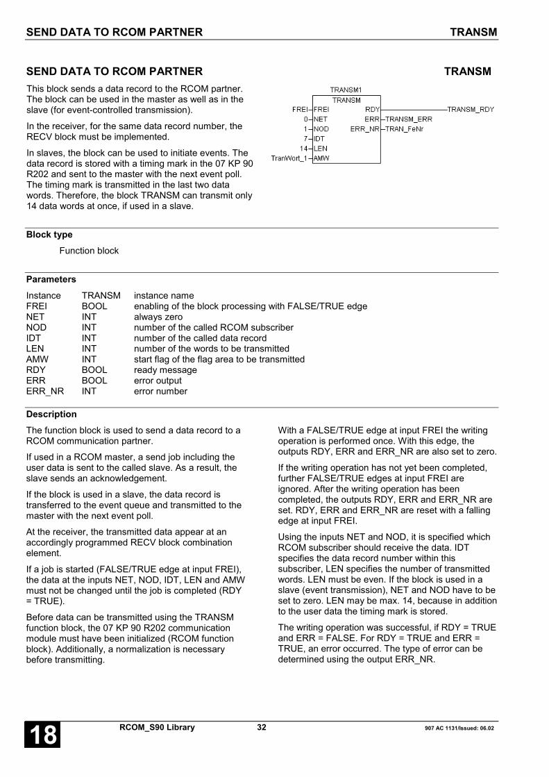
SEND DATA TO RCOM PARTNER TRANSM
RCOM_S90 Library 32 907 AC 1131/Issued: 06.0218
SEND DATA TO RCOM PARTNER TRANSMThis block sends a data record to the RCOM partner.The block can be used in the master as well as in theslave (for event-controlled transmission).
In the receiver, for the same data record number, theRECV block must be implemented.
In slaves, the block can be used to initiate events. Thedata record is stored with a timing mark in the 07 KP 90R202 and sent to the master with the next event poll.The timing mark is transmitted in the last two datawords. Therefore, the block TRANSM can transmit only14 data words at once, if used in a slave.
Block typeFunction block
ParametersInstance TRANSM instance nameFREI BOOL enabling of the block processing with FALSE/TRUE edgeNET INT always zeroNOD INT number of the called RCOM subscriberIDT INT number of the called data recordLEN INT number of the words to be transmittedAMW INT start flag of the flag area to be transmittedRDY BOOL ready messageERR BOOL error outputERR_NR INT error number
DescriptionThe function block is used to send a data record to aRCOM communication partner.
If used in a RCOM master, a send job including theuser data is sent to the called slave. As a result, theslave sends an acknowledgement.
If the block is used in a slave, the data record istransferred to the event queue and transmitted to themaster with the next event poll.
At the receiver, the transmitted data appear at anaccordingly programmed RECV block combinationelement.
If a job is started (FALSE/TRUE edge at input FREI),the data at the inputs NET, NOD, IDT, LEN and AMWmust not be changed until the job is completed (RDY= TRUE).
Before data can be transmitted using the TRANSMfunction block, the 07 KP 90 R202 communicationmodule must have been initialized (RCOM functionblock). Additionally, a normalization is necessarybefore transmitting.
With a FALSE/TRUE edge at input FREI the writingoperation is performed once. With this edge, theoutputs RDY, ERR and ERR_NR are also set to zero.
If the writing operation has not yet been completed,further FALSE/TRUE edges at input FREI areignored. After the writing operation has beencompleted, the outputs RDY, ERR and ERR_NR areset. RDY, ERR and ERR_NR are reset with a fallingedge at input FREI.
Using the inputs NET and NOD, it is specified whichRCOM subscriber should receive the data. IDTspecifies the data record number within thissubscriber, LEN specifies the number of transmittedwords. LEN must be even. If the block is used in aslave (event transmission), NET and NOD have to beset to zero. LEN may be max. 14, because in additionto the user data the timing mark is stored.
The writing operation was successful, if RDY = TRUEand ERR = FALSE. For RDY = TRUE and ERR =TRUE, an error occurred. The type of error can bedetermined using the output ERR_NR.

SEND DATA TO RCOM PARTNER TRANSM
907 AC 1131/Issued: 06.02 33 RCOM_S90 Library 18
FREI BOOLWith a FALSE/TRUE edge at input FREI a writingoperation is performed once. With this FALSE/TRUEedge, the outputs RDY, ERR and ERR_NR are alsoset to zero. If the writing operation has not yet beencompleted (RDY = FALSE), a further FALSE/TRUEedge at input FREI is ignored.
NET INTMust always be zero.
NOD INTAt input NOD, the number of the called RCOMsubscriber is specified. For a transmission frommaster to slave: slave number for event transmission:zero.
IDT INTAt input IDT, the number of the data record to betransmitted is specified.
LEN INTAt the input, the number of words to be transmitted isspecified. For using TRANSM in slaves (eventtransmission), LEN must be < 14. LEN must be even.
AMW INTAt input AMW, the first flag of the flag area to betransmitted is specified. Beginning with this flag, LENflags are transmitted.
RDY BOOLOutput RDY indicates that the writing operation hasbeen completed. This output has always to beconsidered together with the output ERR. Thefollowing applies:
RDY = TRUE and ERR = FALSE: The writingoperation has been completed. The desired variableareas have been sent to the RCOM partner.
RDY = TRUE and ERR = TRUE: An error occurredduring the writing operation. In this case, the errormessage at output ERR_NR can be evaluated.
After a writing operation, a falling edge at input FREIsets the outputs RDY, ERR and ERR_NR to zero.
If the writing operation has not yet been completed(RDY = FALSE) after a FALSE/TRUE edge at inputFREI, a new FALSE/TRUE edge at input FREI isignored.
ERR BOOLOutput ERR indicates whether an error occurredduring the writing. Output ERR has always to beconsidered together with the output RDY. If an erroroccurred during the writing operation, RDY = TRUEand ERR = TRUE are set. The error type can beevaluated using the error number at output ERR_NR.
ERR_NR INTAt output ERR_NR an error number is output. Thisoutput has always to be considered together with theoutputs RDY and ERR.
The error numbers are described in detail in appendix“Error codes”.
Function call in ILCAL TRANSM1(FREI := FREI, NET := NET,
NOD := NOD, IDT := IDT, LEN := LEN,AWM := AWM)
LD TRANSM1.ERRST ERRLD TRANSM1.ERR_NRST ERR_NRLD TRANSM1.RDYST RDYNote: In IL, the function call has to be performed inone line.
Function call in STTRANSM1(FREI := FREI, NET := NET,NOD := NOD, IDT := IDT, LEN := LEN,AWM := AWM)ERR:=TRANSM1.ERRERR_NR:=TRANSM1.ERR_NRRDY:=TRANSM1.RDY

WARM START WARMST
RCOM_S90 Library 34 907 AC 1131/Issued: 06.0218
WARM START WARMSTWith this block, the RCOM master performs a warmstart, i.e. all data records are disabled for the event-controlled transmission and data records which exist inthe event queue are deleted.
Block typeFunction block
ParametersInstance WARMST instance nameFREI BOOL FALSE/TRUE edge at this input initiates warm startNET INT always zeroNOD INT number of the slave to be startedRDY BOOL ready messageERR BOOL error outputERR_NR INT error number
DescriptionThe function block performs a warm start at thecalled slave. Doing so, the event queue is deletedand the transmission of data records is disabled.
The block can be used to resume the communication,e.g. after a transmission error.
After a warm start, always a normalization mustoccur.
FREI BOOLA FALSE/TRUE edge at input FREI initiates a warmstart. Further edges are ignored until RDY hasbecome “TRUE”.
NET INTMust always be zero.
NOD INTNumber of the slave to be started. For NOD=255 allslaves are called.
RDY BOOLOutput RDY indicates that the warm start has beencompleted. This output has always to be consideredtogether with the output ERR. The following applies:
RDY = TRUE and ERR = FALSE: The warm start hasbeen completed. The desired slaves have beenreset.
RDY = TRUE and ERR = TRUE: An error occurredduring the warm start. In this case, the error messageat output ERR_NR can be evaluated.
After a warm start, a falling edge at input FREI setsthe outputs RDY, ERR and ERR_NR to zero.
If the warm start has not yet been completed (RDY =FALSE) after a FALSE/TRUE edge at input FREI, anew FALSE/TRUE edge at input FREI is ignored.
ERR BOOLOutput ERR indicates whether an error occurredduring the warm start. Output ERR has always to beconsidered together with the output RDY.
If an error occurred during the warm start, RDY =TRUE and ERR = TRUE are set. The error type canbe evaluated using the error number at outputERR_NR.
ERR_NR INTAt output ERR_NR an error number is output. Thisoutput has always to be considered together with theoutputs RDY and ERR.
The error numbers are described in detail in appendix“Error codes”.

WARM START WARMST
907 AC 1131/Issued: 06.02 35 RCOM_S90 Library 18
Function call in ILCAL WARMST1(FREI := FREI, NET := NET,
NOD := NOD)
LD WARMST1.ERRST ERRLD WARMST1.ERR_NRST ERR_NRLD WARMST1.RDYST RDY
Note: In IL, the function call has to be performed inone line.
Function call in STWARMST1(FREI := FREI, NET := NET,NOD := NOD);ERR:=WARMST1.ERR;ERR_NR:=WARMST1.ERR_NR;RDY:=WARMST1.RDY;

WARM START WARMST
RCOM_S90 Library 36 907 AC 1131/Issued: 06.0218

907 AC 1131/Issued: 06.02 37 RCOM_S90 Library 18
Glossary
BOOLVariables of the type BOOL can have the values TRUE and FALSE. For this, 8 bit memory space are reserved.
DINTDINT belongs to the integer data types.
The different numerical types are responsible for a different numerical range. For integer data types the followingrange limits are valid:
Type Lower limit Upper limit Memory spaceDINT: -2147483648 2147483647 32 bit
Due to this, it is possible that information are lost when converting greater data types to smaller data types.
DWORDDWORD belongs to the integer data types.
The different numerical types are responsible for a different numerical range. For integer data types the followingrange limits are valid:
Type Lower limit Upper limit Memory spaceDWORD 0 4294967295 32 bit
Due to this, it is possible that information are lost when converting greater data types to smaller data types.
INTINT belongs to the integer data types.
The different numerical types are responsible for a different numerical range. For integer data types the followingrange limits are valid:
Type Lower limit Upper limit Memory spaceINT: -32768 32767 16 bit
Due to this, it is possible that information are lost when converting greater data types to smaller data types.
WORDWORD belongs to the integer data types.
The different numerical types are responsible for a different numerical range. For integer data types the followingrange limits are valid:
Type Lower limit Upper limit Memory spaceWORD 0 65535 16 bit
Due to this, it is possible that information are lost when converting greater data types to smaller data types.
RCOM_S90 Library 38 907 AC 1131/Issued: 06.0218
FunctionsFunctions are subroutines which have multiple input parameters and return exactly one result element. Thereturned result can be of an elementary or a derived data type. Due to this, a function may also return an array, astructure, an array of structures and so on.
For the same input parameters, functions always return the same result (they do not have an internal memory).
Therefore, the following rules are to be derived:
• Within functions, global variables can neither be read nor wrote.• Within functions, absolute operands can neither be read nor wrote.• Within functions, function blocks must not be called.
Function blocksFunction blocks are subroutines which can have as much inputs, outputs and internal variables as required. Theyare called from a program or from another function block.
As they can be used several times (with different data records), function blocks (code and interface) can beconsidered as type. When assigning an individual data record (declaration) to the function block, a function blockinstance is generated.
In contrast to functions, function blocks can contain statically local data which are saved from one call to the next.Therefore, e.g. counters can be realized which may not forget their counter value. I.e. function blocks can have aninternal memory.
Functions and function blocks differ in two essential points:
• A function block has multiple output parameters, a function maximum one, but the output parameters differsyntactically.
• In difference to a function, a function block can have an internal memory.
1. Function blocks with historical values (memory):
For function blocks with historical values it has to be observed that instance names may not be defined severaltimes if different data sets should be called.
2. Function blocks without historical values (memory):
For function blocks without historical values only one instance has to be defined for the FB type. This instance canbe used for several calls of the FB (also with different I/O values).
The instance name can be defined without any restrictions. The type is preset and identical to the function blockname.
907 AC 1131/Issued: 06.02 39 RCOM_S90 Library 18
Index
CCLOCK S90 4
COLDST S90 6
DDIAL S90 8
HHANGUP S90 10
NNORMAL S90 12
PPOLL S90 14
RRCOM S90 16
CLOCK 4
COLDST 6
DIAL 8
HANGUP 10
NORMAL 12
POLL 14
RCOM 16
RCOM_PL 20
READ 24
READ_S 26
RECV 28
SYS_S 30
TRANSM 32
WARMST 34
RCOM_PL S90 20
READ S90 24
READ_S S90 26
RECV S90 28
SSYS_S S90 30
TTRANSM S90 32
WWARMST S90 34

RCOM_S90 Library 40 907 AC 1131/Issued: 06.0218

Software Description Advant Controller 31Intelligent DecentralizedAutomation System
ARCNETFunction Block Library90 Series
ARCNET90 Series


907 AC 1131/Issued: 04.03 1 ARCNET_S90 Library 18
Contents
The ARCNET Library 2SPECIAL FEATURES OF THE ARCNET LIBRARY ................................. 2COMPONENTS OF THE ARCNET LIBRARY ................................. 2
Overview of blocks arranged according to their call names 3INITIALIZATION OF THE ARCNET CONTROLLER AINIT ........................ 4RECEIVE ARCNET DATA PACKAGES AREC ....................... 7SEND ARCNET DATA PACKAGES ASEND(1..16)......... 9INITIALIZATION OF THE ARCNET COUPLER, VARIABLE AINIT_V ............. 11RECEIVE ARCNET DATA PACKAGES AREC_V ................. 16SEND ARCNET DATA PACKAGES TO ONE SUBSCRIBER ASEND_V........ 19READ ARCNET TIMEOUT DATA PACKAGES ASTO_V ................. 22DRIVER FOR THE 5F PROTOCOL VIA ARCNET _5F_ARC97............ 24
Glossary 29
Index 31

THE ARCNET LIBRARY
ARCNET_S90 Library 2 907 AC 1131/Issued: 04.0318
The ARCNET LibrarySPECIAL FEATURES OF THE ARCNET LIBRARYNote:
The ARCNET communication only runs in the RUN mode of the PLC, but not in the simulation mode.
Alterations compared with the blocks of the EBS operating system of the 07 KT 94 basic unit:
Block: AREC
Instead of n duplications AREC is projected n times. In this case it is important that the blocks are projected directlyone behind the other, i.e. not at different positions in the program.
Blocks: ASEND1, ASEND4, ASEND16
The ASEND+ block is replaced by the corresponding ASEND block. Sending the data packages to one (ASEND1),four (ASEND4) or sixteen (ASEND16) subscribers is possible.
COMPONENTS OF THE ARCNET LIBRARY
The following function blocks are contained in the ARCNET library:
Group: ARCNETAINIT - Initialization of the ARCNET controller
AREC - Receive ARCNET data packages
ASEND1 - Send ARCNET data packages to one subscriber
ASEND4 - Send ARCNET data packages to maximum of 4 subscribers
ASEND16 - Send ARCNET data packages to maximum of 16 subscribers
ASENDB - ARCNET sending block for bytes for a maximum of 1 receiver
Group: ARCNET newAINIT_V - Initialization of the ARCNET coupler, variable
ASEND_V - Send ARCNET data package to one subscriber
AREC_V - Receive data packages
ASTO_V - Read ARCNET timeout data packages
Gruppe ARCNET 5F communication_5F_ARC97 - Driver for the 5F protocol via ARCNET
Detailed descriptions of the blocks are in the following sections.

OVERVIEW OF BLOCKS ARRANGED ACCORDING TO THEIR CALL NAMES
907 AC 1131/Issued: 04.03 3 ARCNET_S90 Library 18
Overview of blocks arranged according to their call names
Character descriptions:
FBmV … Function block with historical values
FBoV … Function block without historical values
F … Function
CE Name Type Function Page
_5F_ARC97 FBmV Driver for the 5F protocol via ARCNET 25
AINIT FBmV Initialization of the ARCNET controller 4
AINIT_V FBmV Initialisierung des ARCNET-Kopplers variabel 12
AREC FBmV Receive ARCNET data packages 8
AREC_V FBoV Receive ARCNET data packages 17
ASEND(1..16) FBmV Send ARCNET data packages 10
ASEND_V FBoV Send ARCNET data packages to one subscriber 20
ASTO_V FBoV Read ARCNET timeout data packages 23

AINIT INITIALIZATION OF THE ARCNET CONTROLLER
ARCNET_S90 Library 4 907 AC 1131/Issued: 04.0318
INITIALIZATION OF THE ARCNET CONTROLLER AINITThe operating system initializes the ARCNET controllerin the following way:
– Interrupt after receiving or sending a data package– Only short packages (a short package = 256 bytes)– Reception of broadcasts
Block dataAvailable as of PLC runtime system: V4.0 Remarks:Included in library: ABB-BIB4.LIB
ARCNET_S90_V41.LIB
Block typeFunction block with historical values
ParameterInstance AINIT Instance nameFREI BOOL Enabling of the block processingTout INT Timeout in ms when sending data packagesDONE BOOL Initialization terminatedERR BOOL Error has occurredNODE INT Own node number (station address)STAT INT Status register of the ARCNET controllerDIAG INT Diagnosis register of the ARCNET controllerTOS BOOL Timeout has occurred during send operationTOND INT Node number, timeout data packagesTOJN INT Job number, timeout data packagesLEV INT Level of the send bufferRECO BOOL Network reconfiguration is running (after loss of token)
The outputs STAT, DIAG, TOS, TOND, TOJN, LEV and RECO are updated after a successful initialization witheach block call.
DescriptionThe operating system initializes the ARCNET controllerin the following way:
– Interrupt after receiving or sending a data package– Only short packages (a short package = 256 bytes)– Reception of broadcasts
FREI BOOLA TRUE signal at input FREI causes the processing ofthe block.
TO INTThe timeout waiting time for sending data packages isspecified in ms at input TO. If a data package cannot
be sent within this period, the sending operation of thisdata package is aborted and the package is lost. Theoutput TOS indicates the loss of the package.
DONE BOOLThe output DONE indicates that the initialization hasbeen terminated. This output has always to beconsidered together with output ERR.
The following applies:
DONE = TRUE and ERR = FALSE:The initialization has been terminated. No error hasoccurred.
INITIALIZATION OF THE ARCNET CONTROLLER AINIT
907 AC 1131/Issued: 04.03 5 ARCNET_S90 Library 18
DONE = TRUE and ERR = TRUE:
An error has occurred during initialization. TheARCNET controller has not responded within aperiod of 100 ms.
ERR BOOLThe output ERR indicates that the ARCNET controllerhas not responded after an initialization commandwithin a period of 100 ms. This output has always to beconsidered together with output DONE. If an error hasoccurred, the following applies:
DONE = TRUE and ERR = TRUE.
NODE INTThe output NODE indicates the own node number(station address) after a successful initialization.
STAT INTThe output STAT indicates the content of the statusregister of the ARCNET controller after a successfulinitialization.
DIAG INTThe output DIAG indicates the content of the diagnosisregister of the ARCNET controller after a successfulinitialization.
TOS BOOL
The output TOS indicates that sending of a datapackage was not possible within the timeout period(input TO) and that the data package is lost. Both thenode number and the job number of the lost datapackage are available at the outputs TOND and TOJN,respectively.
TOND INTThe output TOND indicates the node number of the lostdata package after the timeout period has elapsed.
TOJN INTThe output TOJN indicates the job number of the lostdata package after the timeout period has elapsed.
LEV INTThe output LEV indicates the level of the sending bufferafter a successful initialization.
RECO BOOLThe output RECO indicates that the network isreconfiguring itself (RECO = TRUE) after a loss oftoken. The value RECO = FALSE indicates that thereconfiguring procedure has been terminated.
The outputs STAT, DIAG, TOS, TOND, TOJN, LEVand RECO are updated after a successful initializationwith each block call.
The inputs and outputs can neither be duplicated norinverted.

INITIALIZATION OF THE ARCNET CONTROLLER AINIT
ARCNET_S90 Library 6 907 AC 1131/Issued: 04.0318
Function call in ILCAL AINIT1(FREI := AINIT_FREI,
TOut := AINIT_TOut)LD AINIT1.ERRST AINIT_ERRLD AINIT1.NODEST AINIT_NODELD AINIT1.STATST AINIT_STATLD AINIT1.DIAGST AINIT_DIAGLD AINIT1.TOSST AINIT_TOSLD AINIT1.TONDST AINIT_TONDLD AINIT1.TOJNST AINIT_TOJNLD AINIT1.LEVST AINIT_LEVLD AINIT1.RECOST AINIT_RECOLD AINIT1.DONEST AINIT_DONE
Note: The function call in IL has to be performed inone line.
Function call in STAINIT1(FREI := AINIT_FREI, TOut := AINIT_TOut);AINIT_ERR:=AINIT1.ERR;AINIT_NODE:=AINIT1.NODE;AINIT_STAT:=AINIT1.STAT;AINIT_DIAG:=AINIT1.DIAG;AINIT_TOS:=AINIT1.TOS;AINIT_TOND:=AINIT1.TOND;AINIT_TOJN:=AINIT1.TOJN;AINIT_LEV:=AINIT1.LEV;AINIT_RECO:=AINIT1.RECO;AINIT_DONE:=AINIT1.DONE;
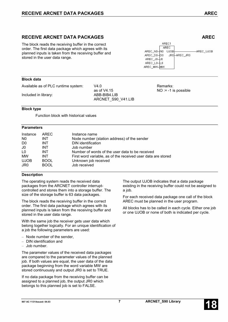
RECEIVE ARCNET DATA PACKAGES AREC
907 AC 1131/Issued: 04.03 7 ARCNET_S90 Library 18
RECEIVE ARCNET DATA PACKAGES ARECThe block reads the receiving buffer in the correctorder. The first data package which agrees with itsplanned inputs is taken from the receiving buffer andstored in the user data range.
Block dataAvailable as of PLC runtime system: V4.0
as of V4.15Remarks:NO := -1 is possible
Included in library: ABB-BIB4.LIBARCNET_S90_V41.LIB
Block typeFunction block with historical values
ParametersInstance AREC Instance nameN0 INT Node number (station address) of the senderD0 INT DIN identificationJ0 INT Job numberL0 INT Number of words of the user data to be receivedMW INT First word variable, as of the received user data are storedUJOB BOOL Unknown job receivedJR0 BOOL Job received
DescriptionThe operating system reads the received datapackages from the ARCNET controller interrupt-controlled and stores them into a storage buffer. Thesize of the storage buffer is 63 data packages.
The block reads the receiving buffer in the correctorder. The first data package which agrees with itsplanned inputs is taken from the receiving buffer andstored in the user data range.
With the same job the receiver gets user data whichbelong together logically. For an unique identification ofa job the following parameters are used:
– Node number of the sender,– DIN identification and– Job number.
The parameter values of the received data packagesare compared to the parameter values of the plannedjob. If both values are equal, the user data of the datapackage beginning from the word variable MW arestored continuously and output JR0 is set to TRUE.
If no data package from the receiving buffer can beassigned to a planned job, the output JR0 whichbelongs to this planned job is set to FALSE.
The output UJOB indicates that a data packageexisting in the receiving buffer could not be assigned toa job.
For each received data package one call of the blockAREC must be planned in the user program.
All blocks has to be called in each cycle. Either one jobor one UJOB or none of both is indicated per cycle.
AREC RECEIVE ARCNET DATA PACKAGES RECEIVE ARCNET DATA PACKAGES
ARCNET_S90 Library 8 907 AC 1131/Issued: 04.0318
N0 INTThe node number (station address) of the sender isspecified for the planned job at input NO.
The following applies: 0 < N0…Nn-1 < 255
As of PLC runtime system V4.15 the entry NO:=-1 ispossible. With this setting, a telegram characterized byJO and DIN, is accepted by all station addresses.
D0 INTThe DIN identification is specified for the planned job atinput D0.
The following applies: D0 = 127 (7FH)not allowed: 111 (6FH)/95 (5FH)/79 (4FH)/63 (3FH)
J0 INTThe job number is specified for the planned job at inputJ0.
The following applies: -32767 < J0 < +32767L0INT
The number of user data words is specified for theplanned job at input L0.
The following applies: 0 < L0 < 125
MW INTThe starting word flag of the user data is specified forthe planned job at input MW.
UJOB BOOLOutput UJOB indicates that a data package was storedin the receiving buffer which could not be assigned toany planned job.
The following applies:
UJOB = TRUE: Unknown job received
UJOB = FALSE: No unknown job received
JR0 BOOLOutput JR0 (job received) indicates that a datapackage from the receiving buffer has been assigned tothis job. The user data of the data package are storedcontinuously beginning from the word variable MW.
The following applies:
JR0 = TRUE: Job receivedJR0 = FALSE: No job received
Note:The inputs and outputs can neither be duplicated norinverted.
Function call in ILCAL AREC1(N0 := AREC_N0, D0 := AREC_D0,
J0 := AREC_J0, L0 := AREC_L0,MW0 := MW0)
LD AREC1.JR0ST AREC_JR0LD AREC1.UJOBST AREC_UJOB
Note: In IL, the function call has to be performed inone line.
Function call in STAREC1(N0 := AREC_N0, D0 := AREC_D0,J0 := AREC_J0, L0 := AREC_L0, MW0 := MW0);AREC_JR0:=AREC1.JR0;AREC_UJOB:=AREC1.UJOB;

SEND ARCNET DATA PACKAGES ASEND(1..16)
907 AC 1131/Issued: 04.03 9 ARCNET_S90 Library 18
SEND ARCNET DATA PACKAGES ASEND(1..16)The ASEND(1..16) block is used to send off jobs (datapackages) via the ARCNET network.
The planned jobs are stored in a sending buffer. Fromhere, they are transferred to the ARCNET controller forsending off.
The ASEND number indicates the maximum number ofnode numbers (receiver). The following ASEND blocksare available:
ASEND1: ARCNET sending block for a maximum of1 receiver
ASEND4: ARCNET sending block for a maximum of4 receivers
ASEND16: ARCNET sending block for a maximum of16 receivers
ASENDB: ARCNET sending block for bytes for amaximum of 1 receiver
Block dataAvailable as of PLC runtime system: V4.0 Remarks:Included in library: ABB-BIB4.LIB
ARCNET_S90_V41.LIB
Block typeFunction block with historical values
ParametersInstance ASEND(1..16,B) Instance nameEN BOOL Enable: Send job
FALSE: do not sendFALSE/TRUE edge: sendTRUE: send only if user data have changed
D0 INT DIN identificationJ0 INT Job numberL0 INT Number of user data words to be sentn INT Number of node numbersN0..Nn-1 INT Node number (station address) of the receiverMW INT First word variable of the user data wordsSTA BOOL Job has been stored in the sending buffer
DescriptionThe ASEND(1..16) block is used to send off jobs (datapackages) via the ARCNET network.
The planned jobs are stored in a sending buffer. Fromhere, they are transferred to the ARCNET controller forsending off.
A maximum of 63 data packages can be stored in thesending buffer.
The output STA indicates that the planned job wasstored in the sending buffer.
If several jobs has to be sent several ASEND(1..16)blocks must be planned.
The ARCNET controller must have been initializedbefore the ASEND(1..16) block can store datapackages in the sending buffer.
ASEND(1..16) SEND ARCNET DATA PACKAGES
ARCNET_S90 Library 10 907 AC 1131/Issued: 04.0318
EN BOOLDependent on the input EN, the planned job is storedas a data package in the sending buffer and sent offafter this.
The following applies:
EN = FALSE:The planned job is not stored in the sending buffer andthus not sent off.
EN = FALSE/TRUE edge:The planned job is stored as a data package in thesending buffer and sent off then.
EN = TRUE:The planned job is stored in the sending buffer, only ifthe user data of the job have changed.
D0 INTThe DIN identification is specified for the planned job atinput D0.
The following applies: D0 = 127 (7FH)not allowed: 111 (6FH)/95 (5FH)/79 (4FH)/ 63 (3FH)
J0 INTThe job number is specified for the planned job at inputJ0.
The following applies: -32767 < J0 < +32767
L0 INTThe number of user data words is specified for theplanned job at input L0.
The following applies: 0 < L0 < 125
n INTThe number of node numbers (receiver) is specified atthis input.
The following applies:0 < n < max. number of receivers (0..15)
N0..Nn-1 INTIf the same job has to be sent to several receivers, thenode numbers (station addresses) of the receivers aredefined at the inputs N0 ... Nn-1.
N0: Node number = 0:If the node number is »0« at input N0, the job is sent toall stations (Broadcast).
N1…Nn-1: Node number = 0:If the node number is »0« at the inputs N1 ... Nn-1, nobroadcast is sent.
If one of the receivers is not able to receive data, thedata package is lost for this receiver.
The following applies: 0 < N0…Nn-1 < 255
MW INTThe starting word flag of the word flag area to be sentoff is specified at input MW. The data of this flag areaare sent off as user data in this job.
STA BOOLThe output STA (status) indicates for one cycle periodthat the planned job has been stored in the sendingbuffer.
The following applies:
STA = FALSE: The planned job has not been stored inthe sending buffer.
STA = TRUE: The planned job has been stored in thesending buffer.
Note:The inputs and outputs can neither be duplicated norinverted.
Function call in ILCAL ASEND11(EN := AS_EN, D0 := AS_D0,
J0 := AS_J0, L0 := AS_L0, n := 1,N0 := AS_N0, MW := AS_MW)
LD ASEND11.STAST AS_STA
Note: In IL, the function call has to be performed inone line.
Function call in STASEND11(EN := AS_EN, D0 := AS_D0, J0 := AS_J0,L0 := AS_L0, n := 1, N0 := AS_N0, MW := AS_MW);AS_STA:=ASEND11.STA;

INITIALIZATION OF THE ARCNET COUPLER, VARIABLE AINIT_V
907 AC 1131/Issued: 04.03 11 ARCNET_S90 Library 18
INITIALIZATION OF THE ARCNET COUPLER, VARIABLE AINIT_VThe AINIT_V block initializes the ARCNET processingfor the blocks ASEND_V, AREC_V and ASTO_V. Theblocks ASEND1, ASEND4, ASEND16, AREC cannotbe run with this blocks at the same time.
In order to make possible programming and MMI viathe ARCNET, the DIP switch for setting the stationaddress must be set unequal to 0 when power isswitched on. The ARCNET coupler then is initialized bythe operating system as follows:
– Interrupt after reception/sending/reconfiguration
– Long packages = 512 bytes
– Accept broadcasts (data packages to all stations)
– Node (station address) of the DIP switch
If the DIP switch is set to 0, the coupler will not beinitialized by the operating system. In this case, it mustbe set to a node (station address) unequal to 0 usingthe AINIT_V block, input SNODE. In this operatingmode, no programming and no MMI via the ARCNETare available. This is indicated by the DISDIN output(Disable DIN identification). In addition, the ENRA inputis not in effect here, i.e. reception is always disabled incase of an imminent buffer overflow.
The AINIT_V block may be planned only once perARCNET coupler.
Block dataAvailable as of PLC runtime system: V4.05 Remarks:Included in library: ARCNET_S90_V41.LIB
Block typeFunction block with historical values
ParametersInstance AINIT_V Instance nameEN BOOL Initialization of the ARCNET coupler with a
FALSE/TRUE edgeCONO INT Slot (card number) of the couplerTOUT INT Timeout in ms for sending of data packages,
standard timeoutSNODE INT Node setting (station address of its own), only in
effect if the DIP switch = 0!LRB INT Length of the receiving buffer in bytesLSHB INT Length of the sending buffer in bytes for high priorityLSLB INT Length of the sending buffer in bytes for low priorityLSTOB INT Length of the buffer for timeout data packages in
bytesLHEAD INT Number of header data in bytes, which are copied
with timeout packagesENBC BOOL Enable/disable broadcast reception (data packages
to all stations)ENLP BOOL Enable/disable long data packages (512 bytes)
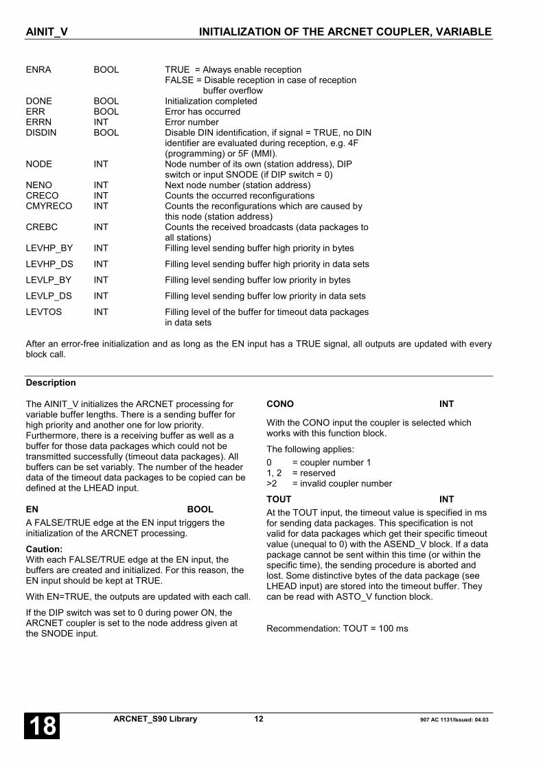
AINIT_V INITIALIZATION OF THE ARCNET COUPLER, VARIABLE
ARCNET_S90 Library 12 907 AC 1131/Issued: 04.0318
ENRA BOOL TRUE = Always enable receptionFALSE = Disable reception in case of reception buffer overflow
DONE BOOL Initialization completedERR BOOL Error has occurredERRN INT Error numberDISDIN BOOL Disable DIN identification, if signal = TRUE, no DIN
identifier are evaluated during reception, e.g. 4F(programming) or 5F (MMI).
NODE INT Node number of its own (station address), DIPswitch or input SNODE (if DIP switch = 0)
NENO INT Next node number (station address)CRECO INT Counts the occurred reconfigurationsCMYRECO INT Counts the reconfigurations which are caused by
this node (station address)CREBC INT Counts the received broadcasts (data packages to
all stations)LEVHP_BY INT Filling level sending buffer high priority in bytes
LEVHP_DS INT Filling level sending buffer high priority in data sets
LEVLP_BY INT Filling level sending buffer low priority in bytes
LEVLP_DS INT Filling level sending buffer low priority in data sets
LEVTOS INT Filling level of the buffer for timeout data packagesin data sets
After an error-free initialization and as long as the EN input has a TRUE signal, all outputs are updated with everyblock call.
Description
The AINIT_V initializes the ARCNET processing forvariable buffer lengths. There is a sending buffer forhigh priority and another one for low priority.Furthermore, there is a receiving buffer as well as abuffer for those data packages which could not betransmitted successfully (timeout data packages). Allbuffers can be set variably. The number of the headerdata of the timeout data packages to be copied can bedefined at the LHEAD input.
EN BOOLA FALSE/TRUE edge at the EN input triggers theinitialization of the ARCNET processing.
Caution:With each FALSE/TRUE edge at the EN input, thebuffers are created and initialized. For this reason, theEN input should be kept at TRUE.
With EN=TRUE, the outputs are updated with each call.
If the DIP switch was set to 0 during power ON, theARCNET coupler is set to the node address given atthe SNODE input.
CONO INT
With the CONO input the coupler is selected whichworks with this function block.
The following applies:0 = coupler number 11, 2 = reserved>2 = invalid coupler number
TOUT INTAt the TOUT input, the timeout value is specified in msfor sending data packages. This specification is notvalid for data packages which get their specific timeoutvalue (unequal to 0) with the ASEND_V block. If a datapackage cannot be sent within this time (or within thespecific time), the sending procedure is aborted andlost. Some distinctive bytes of the data package (seeLHEAD input) are stored into the timeout buffer. Theycan be read with ASTO_V function block.
Recommendation: TOUT = 100 ms

INITIALIZATION OF THE ARCNET COUPLER, VARIABLE AINIT_V
907 AC 1131/Issued: 04.03 13 ARCNET_S90 Library 18
SNODE INT
This input only becomes effective, if during power ONthe DIP switch for setting the node number (stationnumber) was set to 0. In this case, the ARCNETcoupler is initialized with the node number given at theSNODE input.
The following applies: 0 < SNODE <= 255
LRB INTAt the LRB input, the intended length of the receivingbuffer is specified in bytes.
LSHB INTAt the LSHB input, the intended length of the sendingbuffer of high priority is specified in bytes.
LSLB INTAt the LSLB input, the intended length of the sendingbuffer of low priority is specified in bytes.
LSTOB INTAt the LSTOB input, the intended length of the bufferfor the timeout data packages is specified in bytes.
LHEAD INTIn case of timeout data packages, the LHEAD inputspecifies the number of header data which have to becopied into the readable timeout buffer (see alsoASTO_V block). In addition to the header data, thetimeout buffer contains the target node (stationaddress) of this lost package as well as the informationwhether the target node is present in the network at all.
ENBC BOOLENBC = 1 enables the reception of broadcasts (datapackages to all stations) for this node (station address).The ENBC input is continuously evaluated after theinitialization was successful. The input becomeseffective after the coupler has received a telegram andis enabled for the next reception.ENBC = 0 disables the reception of broadcasts.
ENLP BOOLENLP = 1 enables (ENLP = 0 disables) thereception/sending of long data packages. In all cases,the coupler is able to receive long data packages. IfENLP = 1, the received data packages are madeavailable. If ENLP = 0, they are rejected.The ENLP input is continuously evaluated after theinitialization was successful and the EN input has asignal 1. The sending block generates an errormessage if a long package is to be sent and the input isset to 0. In this case, the package will not be sent.
ENRA BOOL
With the ENRA input, the reception via the ARCNET isalways possible (ENRA = TRUE) or impossible(ENRA = FALSE) even if the receiving buffer is full. Fullmeans that there are less than 512 bytes free. TheENRA input is only evaluated if the DIP switch forsetting the station address was unequal to 0 when thepower was switched on.
The following applies:
No reception when receiving buffer is full, if
ENRA = FALSE and DIP switch = 0 orENRA = FALSE and DIP switch unequal to 0 orENRA = TRUE and DIP switch = 0.
With disabling, programming and MMI are no longerpossible.
ENRA = TRUE and DIP switch unequal to 0 means:
Reception is enabled for programming and MMI even ifthe receiving buffer is full. Data may be lost withtelegrams (except MMI and programming).
DONE BOOLThe DONE output indicates that the initialization wascompleted. The DONE output has always to beconsidered together with the ERR output.
The following applies:DONE = TRUE and ERR = FALSE:The initialization was successful. No error occurred.
DONE = TRUE and ERR = TRUE:An error occurred during initialization.
For details see description of the ERN output.
ERR BOOLThe ERR output indicates that the initializationprocedure of the ARCNET processing was notsuccessful. The ERR output has always to beconsidered together with the DONE output. If an erroroccurred, the following applies:DONE = TRUE and ERR = TRUE.

AINIT_V INITIALIZATION OF THE ARCNET COUPLER, VARIABLE
ARCNET_S90 Library 14 907 AC 1131/Issued: 04.0318
ERRN INT
The ERRN output describes an occurred error in detail.The ERRN output values mean:
ERRN = 0 No error
ERRN = 1 Error during initialization. The couplerdid not response or the coupler numberis invalid (>2).
ERRN = 3 Error during creation of thesending/receiving buffer or buffer forthe timeout data sets.
ERRN = 4 Error while setting the node number ofthis station. The SNODE input has aninvalid node number.
ERRN = 5 Error when receiving data.With ENLP = 0, the received packageis a long data package. This error isautomatically deleted as soon as areceived package has an allowedlength again.
ERRN = 6 Receiving buffer is full.Less than 512 bytes are free in thisbuffer. This error is automaticallydeleted as soon as the buffer was readby the AREC block and the free buffermemory becomes more than 512bytes. ERRN = 6 is not generated if theinput ENRA = 1 and the DIP switch forthe station address was set to a valueunequal to 0 during power ON.
NODE INTThe NODE output indicates the coupler's own nodenumber (station address) after an error-freeinitialization.
NENO INTAfter an error-free initialization, the NENO outputindicates the station address of the communicationpartner which gets the token next.
CRECO INTThe CRECO output indicates the number of networkingreconfigurations occurred since the power wasswitched on. Like power OFF/ON, an 0/1 edge at theEN input resets the CRECO output.
CMYRECO INTThe CMYRECO output indicates the number ofnetworking reconfigurations caused by this node(station address) since the power was switched on. Theoutput value can be cleared with an 0/1 edge at the ENinput as well as with power OFF/ON.
CREBC INTThe CREBC output indicates the number of broadcasts(data packages to all stations) which were received bythis node (station address) since the power wasswitched on.
The output value can be cleared with a FALSE/TRUEedge at the EN input as well as with power OFF/ON.
LEVHP_BY INTThe LEVHP_BY output indicates the filling level of thesending buffer (high priority) in bytes provided that theinitialization was successful.
LEVHP_DS INTThe LEVHP_DS output indicates the filling level of thesending buffer (high priority) in data sets provided thatthe initialization was successful.
LEVLP_BY INTThe LEVLP_BY output indicates the filling level of thesending buffer (low priority) in bytes provided that theinitialization was successful.
LEVLP_DS INTThe LEVLP_DS output indicates the filling level of thesending buffer (low priority) in data sets provided thatthe initialization was successful.
LEVTOS INTThe LEVTOS output indicates the filling level of thebuffer for the timeout data packages in data setsprovided that the initialization was successful.

INITIALIZATION OF THE ARCNET COUPLER, VARIABLE AINIT_V
907 AC 1131/Issued: 04.03 15 ARCNET_S90 Library 18
Function call in ILCAL AINIT_V1(EN := AINITV_EN,
TOUT := AINIT_Tout, CONO :=AINITV_CONO, SNODE := AINITV_SNODE,LRB := AINITV_LRB, LSHB :=AINITV_LSHB, LSLB := AINITV_LSHB,LSTOB := AINITV_LSTOB, LHEAD :=AINITV_LHEAD, ENBC := AINITV_ENBC,ENLP := AINITV.ENLP)
LD AINIT_V1.DONE
ST AINITV_DONE
LD AINIT_V1.ERR
ST AINITV_ERR
LD AINIT_V1.ERRN
ST AINITV_ERRN
LD AINIT_V1.DISDIN
ST AINITV_DISDIN
LD AINIT_V1.NODE
ST AINITV_NODE
LD AINIT_V1.NENO
ST AINITV_NENO
LD AINIT_V1.CRECO
ST AINITV_CRECO
LD AINIT_V1.CMYRECO
ST AINITV_CMYRECO
LD AINIT_V1.CREBC
ST AINITV_CREBC
LD AINIT_V1.LEVHP_BY
ST AINITV_LEVHP_BY
LD AINIT_V1.LEVHP_DS
ST AINITV_LEVHP_DS
LD AINIT_V1.LEVLP_BY
ST AINITV_LEVLP_BY
LD AINIT_V1.LEVLP_DS
ST AINITV_LEVLP_DS
LD AINIT_V1.LEVTOS
ST AINITV_LEVTOS
Note: The function call in IL has to be performed inone line.
Function call in STAINIT_V1(EN := AINITV_EN,
TOUT := AINIT_Tout, , CONO :=AINITV_CONO, SNODE := AINITV_SNODE,LRB := AINITV_LRB, LSHB :=AINITV_LSHB, LSLB := AINITV_LSHB,LSTOB := AINITV_LSTOB, LHEAD :=AINITV_LHEAD, ENBC := AINITV_ENBC,ENLP := AINITV_ENLP);
AINITV_DONE := AINIT_V1.DONE;
AINITV_ERR := AINIT_V1.ERR;
AINITV_ERRN := AINIT_V1.ERRN;
AINITV_DISDIN := AINIT_V1.DISDIN;
AINITV_NODE := AINIT_V1.NODE;
AINITV_NENO := AINIT_V1.NENO;
AINITV_CRECO:= AINIT_V1.CRECO;
AINITV_CMYRECO:= AINIT_V1.CMYRECO;
AINITV_CREBC:= AINIT_V1.CREBC;
AINITV_LEVHP_BY:= AINIT_V1.LEVHP_BY;
AINITV_LEVHP_DS:= AINIT_V1.LEVHP_DS;
AINITV_LEVLP_BY:= AINIT_V1.LEVLP_BY;
AINITV_LEVLP_DS:= AINIT_V1.LEVLP_DS;
AINITV_LEVTOS:= AINIT_V1.LEVTOS;

RECEIVE ARCNET DATA PACKAGES AREC_V
ARCNET_S90 Library 16 907 AC 1131/Issued: 04.0318
RECEIVE ARCNET DATA PACKAGES AREC_VThis block reads the next data set from the receivingbuffer and makes the user data available in theplanned memory area (DATA input). The sender'sstation address (NODE output) as well as the length ofthe data package in bytes (LEN output) are furtherinformation of the data package. Furthermore, theblock informs about the filling level of the receivingbuffer in bytes (LEVR_BY output) and in data setsLEVR_DS output).
Block dataAvailable as of PLC runtime system: V4.05 Remarks:Included in library: ARCNET_S90_V41.LIB
Block typeFunction block without historical values
ParametersInstance AREC_V Instance nameEN BOOL Enabling of the block processingCONO INT Slot (card number) of the couplerDATA DWORD Variable, where the received user data is stored. The
variable must be of ARRAY or STRUCT type.NEW BOOL Data package is available.NODE INT Node number (station address) of the senderLEN INT Length of the data package in bytesLEVR_BY INT Filling level of the receiving buffer in bytesLEVR_DS INT Filling level of the receiving buffer in data setsERR BOOL An error occurredERRN INT Error number
DescriptionThe operating system reads the received datapackages from the ARCNET coupler interrupt-controlled and stores them into the receiving buffer.The size of the receiving buffer is defined by theAINIT_V block. It is constructed as a ring buffer withWRITE/READ pointer (FIFO). If there are less than 256bytes free in the receiving buffer, the reception isdisabled and an error is displayed at the AINIT_Vblock. Only if the ENRA input of the AINIT_V block hasa signal 1 and the DIP switch for setting the stationaddress is unequal to 0 during the power ONprocedure, the oldest entry is overwritten again. In thisway, programming and MMI are possible although thereceiving buffer is full. The data packages are storedwith variable lengths. A data package with 16 bytes ofuser data needs exactly 19 bytes in the receiving buffer(user data + sender's node + package length).
The AREC_V block transfers exactly one datapackage, which is defined by the READ pointer, fromthe receiving buffer to the planned user memory (DATAinput).
The data reception is indicated by the NEW output. TheREAD pointer is incremented then accordingly.
The ARCNET processing must have been initializedwith the AINI_V block before data packages can beread from the receiving buffer with the AREC_V block.
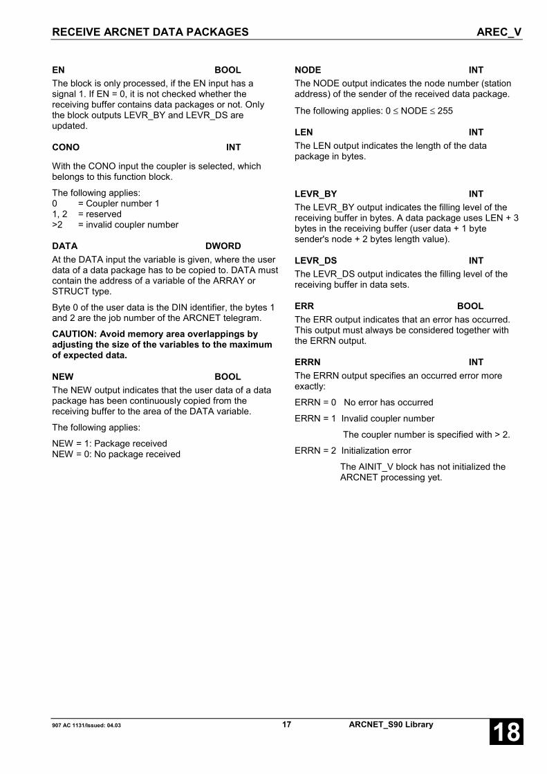
RECEIVE ARCNET DATA PACKAGES AREC_V
907 AC 1131/Issued: 04.03 17 ARCNET_S90 Library 18
EN BOOLThe block is only processed, if the EN input has asignal 1. If EN = 0, it is not checked whether thereceiving buffer contains data packages or not. Onlythe block outputs LEVR_BY and LEVR_DS areupdated.
CONO INT
With the CONO input the coupler is selected, whichbelongs to this function block.
The following applies:0 = Coupler number 11, 2 = reserved>2 = invalid coupler number
DATA DWORDAt the DATA input the variable is given, where the userdata of a data package has to be copied to. DATA mustcontain the address of a variable of the ARRAY orSTRUCT type.
Byte 0 of the user data is the DIN identifier, the bytes 1and 2 are the job number of the ARCNET telegram.
CAUTION: Avoid memory area overlappings byadjusting the size of the variables to the maximumof expected data.
NEW BOOLThe NEW output indicates that the user data of a datapackage has been continuously copied from thereceiving buffer to the area of the DATA variable.
The following applies:
NEW = 1: Package receivedNEW = 0: No package received
NODE INTThe NODE output indicates the node number (stationaddress) of the sender of the received data package.
The following applies: 0 ≤ NODE ≤ 255
LEN INTThe LEN output indicates the length of the datapackage in bytes.
LEVR_BY INTThe LEVR_BY output indicates the filling level of thereceiving buffer in bytes. A data package uses LEN + 3bytes in the receiving buffer (user data + 1 bytesender's node + 2 bytes length value).
LEVR_DS INTThe LEVR_DS output indicates the filling level of thereceiving buffer in data sets.
ERR BOOLThe ERR output indicates that an error has occurred.This output must always be considered together withthe ERRN output.
ERRN INTThe ERRN output specifies an occurred error moreexactly:
ERRN = 0 No error has occurred
ERRN = 1 Invalid coupler number
The coupler number is specified with > 2.
ERRN = 2 Initialization error
The AINIT_V block has not initialized theARCNET processing yet.

RECEIVE ARCNET DATA PACKAGES AREC_V
ARCNET_S90 Library 18 907 AC 1131/Issued: 04.0318
Function call in ILCAL AREC_V1(EN := ARECV_EN, CONO :=
ARECV_CONO, DATA := ARECV_DATA)
LD AREC_V1.NEW
ST ARECV_NEW
LD AREC_V1.NODE
ST ARECV_NODE
LD AREC_V1.LEN
ST ARECV_LEN
LD AREC_V1.LEVR_BY
ST ARECV_LEVR_BY
LD AREC_V1.LEVR_DS
ST ARECV_LEVR_DS
LD AREC_V1.ERR
ST ARECV_ERR
LD AREC_V1.ERRN
ST ARECV_ERRN
Note: The function call in IL has to be performed inone line.
Function call in STAREC_V1(EN := ARECV_EN, CONO :=
ARECV_CONO, DATA := ARECV_DATA);
ARECV_NEW:= AREC_V1.NEW;
ARECV_NODE:= AREC_V1.NODE;
ARECV_LEN:= AREC_V1.LEN;
ARECV_LEVR_BY:= AREC_V1.LEVR_BY;
ARECV_LEVR_DS:= AREC_V1.LEVR_DS;
ARECV_ERR:= AREC_V1.ERR;
ARECV_ERRN:= AREC_V1.ERRN;
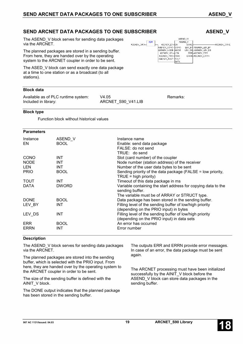
SEND ARCNET DATA PACKAGES TO ONE SUBSCRIBER ASEND_V
907 AC 1131/Issued: 04.03 19 ARCNET_S90 Library 18
SEND ARCNET DATA PACKAGES TO ONE SUBSCRIBER ASEND_VThe ASEND_V block serves for sending data packagesvia the ARCNET.
The planned packages are stored in a sending buffer.From here, they are handed over by the operatingsystem to the ARCNET coupler in order to be sent.
The ASED_V block can send exactly one data packageat a time to one station or as a broadcast (to allstations).
Block dataAvailable as of PLC runtime system: V4.05 Remarks:Included in library: ARCNET_S90_V41.LIB
Block typeFunction block without historical values
ParametersInstance ASEND_V Instance nameEN BOOL Enable: send data package
FALSE: do not sendTRUE: do send
CONO INT Slot (card number) of the couplerNODE INT Node number (station address) of the receiverLEN INT Number of the user data bytes to be sentPRIO BOOL Sending priority of the data package (FALSE = low priority,
TRUE = high priority)TOUT INT Timeout of this data package in msDATA DWORD Variable containing the start address for copying data to the
sending buffer.The variable must be of ARRAY or STRUCT type.
DONE BOOL Data package has been stored in the sending buffer.LEV_BY INT Filling level of the sending buffer of low/high priority
(depending on the PRIO input) in bytesLEV_DS INT Filling level of the sending buffer of low/high priority
(depending on the PRIO input) in data setsERR BOOL An error has occurredERRN INT Error number
DescriptionThe ASEND_V block serves for sending data packagesvia the ARCNET.
The planned packages are stored into the sendingbuffer, which is selected with the PRIO input. Fromhere, they are handed over by the operating system tothe ARCNET coupler in order to be sent.
The size of the sending buffer is defined with theAINIT_V block.
The DONE output indicates that the planned packagehas been stored in the sending buffer.
The outputs ERR and ERRN provide error messages.In case of an error, the data package must be sentagain.
The ARCNET processing must have been initializedsuccessfully by the AINIT_V block before theASEND_V block can store data packages in thesending buffer.

ASEND_V SEND ARCNET DATA PACKAGES TO ONE SUBSCRIBER
ARCNET_S90 Library 20 907 AC 1131/Issued: 04.0318
EN BOOLThe planned package is stored in the sending bufferand then sent depending on the status of the EN input.
The following applies:
EN = FALSE: The planned package is not stored inthe sending buffer and not sent.
EN = TRUE: The planned package is stored in thesending buffer and then sent.
CONO INT
With the CONO input the coupler is selected whichworks with this function block.
The following applies:0 = coupler number 11, 2 = reserved>2 = invalid coupler number
NODE INTThe node number (station address) of the receiver isspecified at the NODE input.
If the node number »0« is specified, the data packageis sent to all stations (broadcast).
If in case of broadcasting one of the receivers is notready for reception, this receiver will never receive thedata package.
The following applies: 0 ≤ NODE ≤ 255
LEN INTThe number of user data bytes of the planned packageis specified at the LEN input.
The following applies:
1 ≤ LEN ≤ 253 for short data packages
1 ≤ LEN ≤ 508 for long data packages
For both data packages, the values 0, 254, 255 and256 bytes are always forbidden.
PRIO BOOL
The PRIO input specifies the sending priority of thedata package.
The following applies:
PRIO = FALSE: The planned data package has a lowpriority. It is entered into the sendingbuffer for low priority. All outputs referto this buffer.
PRIO = TRUE: The planned data package has a highpriority. It is entered into the sendingbuffer for high priority. All outputsrefer to this buffer.
TOUT INTAt the TOUT input, the timeout value is specified in msfor sending data packages. If a data package cannot besent within this time, the sending procedure is abortedand lost. Some distinctive bytes of the data package(see LHEAD input at the AINIT_V block) are stored intothe timeout buffer. They can be read with ASTO_Vfunction block.
The following applies:
TOUT = 0: The planned package does not haveany specific timeout value. The sendingmonitoring uses the timeoutspecification which is given at theTOUT input of the AINIT_V block.
TOUT > 0: The planned package is sent with thespecified timeout value.
Recommendation: TOUT = 100 ms
DATA DWORDAt the DATA input, the variable is specified, whose datais sent in this package as user data. DATA mustcontain the address of a variable of ARRAY orSTRUCT type.
Byte 0 of the user data is the DIN identifier, the bytes 1and 2 are the job number of the ARCNET telegram.
DONE BOOLThe DONE output indicates whether or not the plannedpackage has been stored in the sending buffer.
The following applies:
DONE = 0: The planned package has not been storedin the sending buffer.
DONE = 1: The planned package has been stored inthe sending buffer.
LEV_BY INTThe LEV_BY output indicates the filling level in bytes ofthe sending buffer which was selected with the PRIOinput. One data package uses LEN + 5 bytes in thesending buffer (user data + 1 byte for receiver's node +2 bytes for the length value + 2 bytes for the specifictimeout value).
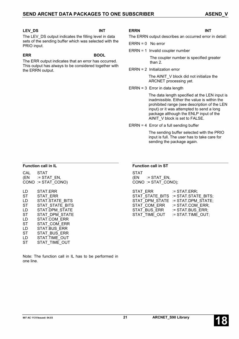
SEND ARCNET DATA PACKAGES TO ONE SUBSCRIBER ASEND_V
907 AC 1131/Issued: 04.03 21 ARCNET_S90 Library 18
LEV_DS INTThe LEV_DS output indicates the filling level in datasets of the sending buffer which was selected with thePRIO input.
ERR BOOLThe ERR output indicates that an error has occurred.This output has always to be considered together withthe ERRN output.
ERRN INTThe ERRN output describes an occurred error in detail:
ERRN = 0 No error
ERRN = 1 Invalid coupler number
The coupler number is specified greaterthan 2.
ERRN = 2 Initialization error
The AINIT_V block did not initialize theARCNET processing yet.
ERRN = 3 Error in data length
The data length specified at the LEN input isinadmissible. Either the value is within theprohibited range (see description of the LENinput) or it was attempted to send a longpackage although the ENLP input of theAINIT_V block is set to FALSE.
ERRN = 4 Error of a full sending buffer
The sending buffer selected with the PRIOinput is full. The user has to take care forsending the package again.
Function call in ILCAL STAT(EN := STAT_EN,CONO := STAT_CONO)
LD STAT.ERRST STAT_ERRLD STAT.STATE_BITSST STAT_STATE_BITSLD STAT.DPM_STATEST STAT_DPM_STATELD STAT.COM_ERRST STAT_COM_ERRLD STAT.BUS_ERRST STAT_BUS_ERRLD STAT.TIME_OUTST STAT_TIME_OUT
Note: The function call in IL has to be performed inone line.
Function call in STSTAT(EN := STAT_EN,CONO := STAT_CONO);
STAT_ERR := STAT.ERR;STAT_STATE_BITS := STAT.STATE_BITS;STAT_DPM_STATE := STAT.DPM_STATE;STAT_COM_ERR := STAT.COM_ERR;STAT_BUS_ERR := STAT.BUS_ERR;STAT_TIME_OUT := STAT.TIME_OUT;

READ ARCNET TIMEOUT DATA PACKAGES ASTO_V
ARCNET_S90 Library 22 907 AC 1131/Issued: 04.0318
READ ARCNET TIMEOUT DATA PACKAGES ASTO_VIf the sending monitoring time expires while sending adata package, the data package has not reached thereceiver. The following information is stored in thetimeout data buffer then: the receiver address, the firstheader data of the data package (see LHEAD input ofthe AINIT_V block for the number of them) andinformation whether the receiver was found in thenetworking or not. This block reads such lost datapackages from the timeout data buffer and providestheir information to the user.
Block dataAvailable as of PLC runtime system: V4.05 Remarks:Included in library: ARCNET_S90_V41.LIB
Block typeFunction block without historical values
ParametersInstance ASTO_V Instance nameEN BOOL enable for the block processingCONO INT Slot (card number) of the couplerDATA DWORD Address of a variable as of where the data of the timeout
package are placed. The variable must be of ARRAY orSTRUCT type.
NEW BOOL Data package is providedLEVDS INT Filling level of the timeout data package in data setsERR BOOL An error occurredERRN INT Error number
DescriptionThe sending procedure of a data package is monitoredby a settable timeout value. If the timeout expires,distinctive information about the involved data packageis placed into the timeout data buffer. There are insuccession:
- Node ID (station address) of the receiver(1 byte)
- Receiver is in the networking or not(1 byte),0 = receiver is not in the networking or itwas attempted to send a long package to anode which was initialized only forreceiving short packages.1 = Receiver is in the networking
- Header data of the data set (the number ofthem is planned at the LHEAD input of theAINIT_V block).
The buffer length is settable at the LSTOB input of theAINIT_V block. It is constructed as a ring buffer (FIFO).If it is full, the oldest entry is overwritten again. TheASTO_V block checks with a signal 1 at the EN input,whether a data package was placed in the buffer andprovides the above mentioned information to the useras of the variable given at the DATA input.
The ASTO_V block only can operate if the ARCNETprocessing was successfully initialized by the AINIT_Vblock.
EN BOOLThe block is processed as long as the EN input has aTRUE signal.
READ ARCNET TIMEOUT DATA PACKAGES ASTO_V
907 AC 1131/Issued: 04.03 23 ARCNET_S90 Library 18
CONO INT
The CONO input selects the coupler which workstogether with this block.
The following applies:0 = coupler number 11, 2 = reserved>2 = invalid coupler number
DATA DWORDAt the DATA input, the variable is given where theinformation of the current data package is copied tocontinuously.
DATA must contain the address of a variable ofARRAY or STRUCT type.
CAUTION: Avoid memory area overlappings byadjusting the size of the variables to the maximumof expected data.
NEW BOOLThe NEW output indicates that the information of a datapackage has been continuously copied from thetimeout data buffer into the area beginning at thevariable given at the DATA input.
The following applies:
NEW = TRUE: Information copiedNEW = FALSE: No information available
ERR BOOLThe ERR output indicates that an error has occurred.This output has always to be considered together withthe ERRN output.
ERRN INTThe ERRN output specifies an occurred error in detail:
ERRN = 0 No error
ERRN = 1 Invalid coupler number
A coupler number >2 is given.
ERRN = 2 Initialization error
The AINIT_V block has not initialized theARCNET processing yet.
Function call in ILCAL ASTO_V1(EN := ASTOV_EN, CONO :=
ASTOV_CONO, DATA := ASTOV_DATA)
LD ASTO_V1.NEW
ST ASTOV_NEW
LD ASTO_V1.LEVDS
ST ASTOV_LEVDS
LD ASTO_V1.ERR
ST ASTOV_ERR
LD ASTO_V1.ERRN
ST ASTOV_ERRN
Note: The function call in IL has to be performed inone line.
Function call in STASTO_V1(EN := ASTOV_EN, CONO :=
ASTOV_CONO, DATA := ASTOV_DATA);
ASTOV_NEW:= ASTO_V1.NEW;
ASTOV_LEVDS:= ASTO_V1.LEVDS;
ASTOV_ERR:= ASTO_V1.ERR;
ASTOV_ERRN:= ASTO_V1.ERRN;

_5F_ARC97 DRIVER FOR THE 5F PROTOCOL VIA ARCNET
ARCNET_S90 Library 24 907 AC 1131/Issued: 04.0318
DRIVER FOR THE 5F PROTOCOL VIA ARCNET _5F_ARC97The _5F_ARC97 block realizes a driver for the 5Fprotocol via ARCNET. The block works independentlyof other ARCNET blocks used at the same time.However, only one _5F_ARC97 block may exist. It isnot necessary to use an AINIT block.The _5F_ARC97 block can work for 1...255 masters.The exact number of masters with the 5F protocol isdefined by the user by creating the correspondingcommunication buffers in the PLC program. The blockmanages the data in these communication buffers asring memories.
All outputs are updated with every block call provided that the initialization was successful.
Block dataAvailable as of PLC runtime system: V4.05
as of V4.15
as of V4.16
Remarks:Telegrams with CP<>3 arerecognizedMasters with node >= 128 arerecognized
Included in library: ARCNET_S90_V41.LIB
Block typeFunction block with 22 bytes of historical values
ParametersInstance _5F_ARC97 Instance nameN INT Number of masters with 5F protocol_5F_MASTER POINTER TO INT Pointer to ARRAY OF INT_5F_BUF POINTER TO _5F_DATA_TYP Pointer to the data memory for 5F telegramsMASTER WORD Master address processed lastRDY BOOL Telegram receivedERR INT Error numberVOLL BOOL Indication "data memory is full“
Description
In order to get an easy-to-use and effective data transmission between the PLC and visualization systems, aprotocol according to MODBUS was realized. The protocol employs the 5FHEX = 95DEZ DIN identification. ARCNETcommunication with other DIN identifications, e.g. using the AREC and ASEND blocks as well as programming viaARCNET is also possible. The protocol uses the master/slave principle. The visualization system always works asthe master, and the PLC always as the slave. In the visualization system it is configured, which data are to be sentor received. In the PLC always a standard program is used.
The _5F_ARC97 block realizes a driver for the 5F protocol via ARCNET. The block works independently of otherARCNET blocks used at the same time. However, only one _5F_ARC97 block may exist. It is not necessary to usean AINIT block. The _5F_ARC97 block can work for 1...255 masters. The exact number of masters with the 5Fprotocol is defined by the user by creating the corresponding communication buffers in the PLC program. The blockmanages the data in these communication buffers as ring memories.

DRIVER FOR THE 5F PROTOCOL VIA ARCNET _5F_ARC97
907 AC 1131/Issued: 04.03 25 ARCNET_S90 Library 18
The telegrams consist of an ARCNET header (CP, DIN, JOB_NR), a counter and the MODBUS telegram whichmay be max. 124 words or 248 bytes of size. All telegrams are sent with the 5F DIN identification. The ARCNETaddress of the corresponding participant is always the JOB number.
The ARCNET telegram is composed in the following way:
Sen-der
Recei-ver
CP DIN MASTERLow
MASTERHigh
CounterLow
CounterHigh
SLAVE FCT User data
Value 03 5F xx 00 aa aa yy zz
Byte 0 1 2 3 4 5 6 7 8 9 10-255
• xx = ARCNET address of the master == JOB No at the AREC/ASEND block
• yy = ARCNET address of the slave, as of here the MODBUS telegram begins
• aaaa = Counter, is updated by the master and reflected by the slave (in order to avoid telegram duplication).This counter is not used for the checksum.
• zz = MODBUS function code
As of the FCT function code, the structure of the telegram follows the MODBUS standard. The telegrams areentered in the communication buffer (see _5F_BUF). The first half of the buffer is used for reception, the secondhalf for sending. Here, one telegram needs 256 bytes.
N INTThe number of planned masters is specified at the Ninput. This number must be equal to the number ofelements in the ARRAYS, which are pointing to_5F_MASTER and _5F_BUF. The 5F_BUF array isN+1 elements in size.
_5F_MASTER POINTER TO INT
In order to manage more than 1 master with the 5Fprotocol, an ARRAY OF INT must be set upcontaining the ARCNET addresses of theparticipants. If only one master exists, a single INTvalue is sufficient. A pointer to this value or to the firstvalue of the array is set to the _5F_MASTER input(see ADR operator).
_5F_BUF POINTER TO _5F_DATA_TYP
In the PLC program, a communication buffer has tobe built an ARRAY of ARRAY OF _5F_DATA_TYPtype. The ARRAY must have N+1 (N = number of themasters) elements. A pointer to the first element ofthe array is specified at the _5F_BUF input.
MASTER INT
The ARCNET address of the telegram last processedby the block is present at the MASTER output. Ifseveral masters are connected, the block runsthrough a loop in order to process all receivedtelegrams.
RDY BOOLThe RDY output is set when the block has processeda telegram.
ERR INTThe ERR output indicates an error number. The errornumber is the error number of the MODBUS protocol.
VOLL BOOLThis output is set, if more telegrams were receivedthan the communication buffer could load. This is thecase if either masters sent more than one telegramper cycle or, participants, that are not entered in the5F_MASTER ARRAY, have sent telegrams with 5FDIN identification. The communication buffer as wellas the ARRAY can be expanded then and the N inputmay be given a greater value accordingly.

_5F_ARC97 DRIVER FOR THE 5F PROTOCOL VIA ARCNET
ARCNET_S90 Library 26 907 AC 1131/Issued: 04.0318
Function call in ILLD a_5F_Master[1]ADRST ARC97_1._5F_MASTERLD aARC_BUF[0]ADRST ARC97_1._5F_BUFCAL ARC97_1(n := iAnzMaster)
LD ARC97_1.MASTERST ARC_Master
LD ARC97_1.RDYST ARC_RDY
LD ARC97_1.ERRST ARC_ERR
LD ARC97_1.VOLLST ARC_VOLL
Note: The function call in IL has to be performed inone line.
Function call in ST
ARC97_1(n := iAnzMaster,_5F_MASTER := ADR(a_5F_Master[1]),_5F_BUF := ADR(aARC_BUF[0]));
ARC_Master := ARC97_1.MASTER;ARC_RDY := ARC97_1.RDY;ARC_ERR := ARC97_1.ERR;ARC_VOLL := ARC97_1.VOLL;
DRIVER FOR THE 5F PROTOCOL VIA ARCNET _5F_ARC97
907 AC 1131/Issued: 04.03 27 ARCNET_S90 Library 18
Programming example (in ST):
PROGRAM ARC_5FVAR CONSTANT
iAnzMaster : INT := 2; (* Number of masters *)END_VARVAR
a_5F_Master : ARRAY[1..iAnzMaster] OF INT := 1, 10; (* Node numbers of the masters *)(* with one master: a_5F_Master : INT := 1; (* Master has node number 1 *)
ARC97_1 : _5F_ARC97; (* Instance *)aARC_BUF : ARRAY[0..iAnzMaster] OF _5F_DATA_TYP; (* Telegram buffer size: iAnzMaster+1 ! *)ARC_Master : INT; (* optional: Node of the master processed last *)ARC_RDY : BOOL; (* optional: Telegram processed *)ARC_ERR : INT; (* optional: Error number see MODMAST *)ARC_VOLL : BOOL; (* optional: Buffer overflow *)iTeleCounter : INT; (* optional: Telegram counter local *)MW00_00 AT %MW1000.0 : INT; (* optional: Telegram counter for transmission *)
END_VAR
(* Block call of _5F_ARC97 *)ARC97_1(n := iAnzMaster,
_5F_MASTER := ADR(a_5F_Master[1]),_5F_BUF := ADR(aARC_BUF[0]));
ARC_Master := ARC97_1.MASTER; (* just for display, can be deleted *)ARC_RDY := ARC97_1.RDY; (* just for display, can be deleted *)ARC_ERR := ARC97_1.ERR; (* just for display, can be deleted *)ARC_VOLL := ARC97_1.VOLL; (* just for display, can be deleted *)
(* Counter for the telegrams / just for indication that the communication is running *)iTeleCounter := SEL(ARC_RDY, iTeleCounter, iTeleCounter+1);MW00_00 := SEL(F_TRIG1.Q, MW00_00, MW00_00+1);(* If MW00_00 is used in the project, comment out here *)

_5F_ARC97 DRIVER FOR THE 5F PROTOCOL VIA ARCNET
ARCNET_S90 Library 28 907 AC 1131/Issued: 04.0318
907 AC 1131/Issued: 04.03 29 ARCNET_S90 Library 18
Glossary
BOOLVariables of the type BOOL can have the values TRUE and FALSE. For this, 8 bit memory space are reserved.
DINTDINT belongs to the integer data types.
The different numerical types are responsible for a different numerical range. For integer data types the followingrange limits are valid:
Type Lower limit Upper limit Memory spaceDINT: -2147483648 2147483647 32 Bit
Due to this, it is possible that information are lost during the conversion of greater data types to smaller data types.
DWORDDWORD belongs to the integer data types.
The different numerical types are responsible for a different numerical range. For integer data types the followingrange limits are valid:
Type Lower limit Upper limit Memory spaceDWORD 0 4294967295 32 Bit
Due to this, it is possible that information are lost during the conversion of greater data types to smaller data types.
INTINT belongs to the integer data types.
The different numerical types are responsible for a different numerical range. For integer data types the followingrange limits are valid:
Type Lower limit Upper limit Memory spaceINT: -32768 32767 16 Bit
Due to this, it is possible that information are lost during the conversion of greater data types to smaller data types.
WORDWORD belongs to the integer data types.
The different numerical types are responsible for a different numerical range. For integer data types the followingrange limits are valid:
Type Lower limit Upper limit Memory spaceWORD 0 65535 16 Bit
Due to this, it is possible that information are lost during the conversion of greater data types to smaller data types.
ARCNET_S90 Library 30 907 AC 1131/Issued: 04.0318
FunctionsFunctions are subroutines which have multiple input parameters and return exactly one result element. Thereturned result can be of an elementary or a derived data type. Due to this, a function may also return an array, astructure, an array of structures and so on.
For the same input parameters, functions always return the same result (they do not have an internal memory).
Therefore, the following rules can derived:
• Within functions, global variables can neither be read nor written.• Within functions, it is not allowed to read or write absolute operands.• Within functions, it is not allowed to call function blocks.
Function blocksFunction blocks are subroutines which can have as much inputs, outputs and internal variables as required. Theyare called by a program or by another function block.
As they can be used several times (with different data records), function blocks (code and interface) can beconsidered as type. When assigning an individual data record (declaration) to the function block, a function blockinstance is generated.
In contrast to functions, function blocks can contain statically local data which are saved from one call to the next.This allows for example to realize counters which may not forget their counter value. I.e. function blocks can havean internal memory.
Functions and function blocks differ in two essential points:
• A function block has multiple output parameters. A function has maximally one output parameter. Note thatthe output parameters of functions and function blocks differ syntactically.
• In contrast to a function, a function block can have an internal memory.
1. Function blocks with historical values (memory):
For function blocks with historical values it has to be observed that instance names may not be defined severaltimes if different data sets should be called.
2. Function blocks without historical values (memory):
For function blocks without historical values only one instance has to be defined for the FB type. This instance canbe used for several calls of the FB (also with different I/O values).
The instance name can be defined without any restrictions. The type is preset and identical to the function blockname.

907 AC 1131/Issued: 04.03 31 ARCNET_S90 Library 18
Index
__5F_ARC97 S90 24
AAINIT S90 4
AINIT_V S90 11
ARCNET S90
_5F_ARC97 24
AINIT 4
AINIT_V 11
AREC 7, 16
ASEND 9
ASEND_V 19
ASTO_V 22
AREC S90 7, 16
ASEND S90 9
ASEND_V S90 19
ASTO_V S90 22
CComponents of the ARCNET library 2

ARCNET_S90 Library 32 907 AC 1131/Issued: 04.0318
Software Description Advant Controller 31Intelligent DecentralizedAutomation System
Function Blocksfor the CS31-Bus90 Series
CS31 Bus90 Series


907 AC 1131/Issued: 06.02 1 CS31_S90 Library 18
Contents
The CS31 Library 2PRECONDITIONS FOR THE USE OF THE CS31 LIBRARY................................ 2COMPONENTS OF THE CS31 LIBRARY .................................. 2
Overview of blocks arranged according to their call names 2CONFIGURE AC31 MODULES CS31CO ................... 3ACKNOWLEDGE AC31 ERRORS CS31QU ................. 10TESTING OF AC31 MODULES CS31TE .................. 11
Glossary 13
Index 15

THE CS31 LIBRARY
CS31_S90 Library 2 907 AC 1131/Issued: 06.0218
The CS31 LibraryPRECONDITIONS FOR THE USE OF THE CS31 LIBRARYNote:
The blocks of the CS31 library only run in the RUN mode of the PLC, but not in the simulation mode.
COMPONENTS OF THE CS31 LIBRARY
The following function blocks are contained in the CS31 library:
CS31CO - Configure AC31 modules
CS31QU - Acknowledge AC31 errors
CS31TE - Testing of AC31 modules
Detailed descriptions of the blocks are in the following sections.
Overview of blocks arranged according to their call names
Character descriptions:
FBmV … Function block with historical values
FBoV … Function block without historical values
F … Function
CE Name Type Function Page
CS31CO FBmV Configure AC31 modules 3
CS31QU FboV Acknowledge AC31 errors 10
CS31TE FboV Testing of AC31 modules 11

CONFIGURE AC31 MODULES CS31CO
907 AC 1131/Issued: 06.02 3 CS31_S90 Library 18
CONFIGURE AC31 MODULES CS31COThe function block is used to configure the AC31remote modules. The block can both sendconfiguration parameters to the remote modules andalso scan their currently set configuration.
Block typeFunction block with historical values
ParametersInstance CS31CO Instance nameFREI BOOL Enable (FALSE/TRUE edge) for processing the blockGRN INT Group number of the remote module to which the job refersCODE INT Identification of the job to be performedD1 INT 1st parameter of the job. . .. . .D8 INT 8th parameter of the jobRDY BOOL Processing of the job is completedOK BOOL The job could be processed correctlyERR INT Error message/status messageA1 INT 1st parameter of the response. . .. . .A7 INT 7th parameter of the response
DescriptionThe function block is used to configure the AC31remote modules. The block can both send configurationparameters to the remote modules and also scan theircurrently set configuration.
Apart from configuration of the AC31 remote modules,the function block can also process further jobs (see listof jobs).
Enable for processing a job once is triggered by aFALSE/TRUE edge at input FREI.
The required job identification is specified at inputCODE.
The parameters required for the job are planned at theinputs D1 ... D8.
Status messages are signalized at the outputs RDY,OK and ERR.
The response data of the job are available at theoutputs A1 ... A7.
It may take several PLC cycles to process the job.

CONFIGURE AC31 MODULES CS31CO
CS31_S90 Library 4 907 AC 1131/Issued: 06.0218
FREI BOOLProcessing of the block is controlled via input FREI.
FREI = FALSE:All block outputs are set to the value »FALSE«.However, this is not valid, if a job is currently beingprocessed, i. e. processing of a job which is currentlybeing processed, is not affected by FREI = FALSE.
FREI = FALSE/TRUE edge:Processing of the job is enabled.Input FREI is no longer evaluated during processing ofthe job.
FREI = TRUE:The block is not processed, i. e. it no longer changes itsoutputs. However, this is not valid, if a job is currentlybeing processed.
GRN INTGroup number with which the remote module isaddressed by the PLC program.
Range: 0 … 63
Example:On binary input E 12,08, »12« is the group number and»08« is the channel number.
CODE INTThe identification of the job to be executed is specifiedat input CODE (see list of jobs on the next page).
D1…D8 INTThe parameters required for the job are preset at theinputs D1 ... D8. The number of parameters dependson the job to be executed. There are also jobs requiringno parameters (see list of jobs on the next page).
RDY BOOLThe output RDY indicates that processing of the jobcurrently being processed is completed. This outputdoes not indicate whether processing of the job wassuccessful or not. The output RDY has thereforealways to be considered together with the output OK.
RDY = TRUE and OK = TRUE:Processing of the job is completed without errors. Anew.
Job can be started with a FALSE/TRUE edge at inputFREI.
RDY = TRUE and OK = FALSE:During processing of the job an error has beendetected. The corresponding error identification ispresent at output ERR. A new job can be started with aFALSE/TRUE edge at input FREI.
RDY = FALSE:Processing of an enabled job has not yet beencompleted
(job is still running) or output RDY has been reset withFREI = FALSE.
OK BOOLOutput OK indicates whether the job has been handledsuccessfully or whether an error has been detectedduring processing. In case of an error, an error numberis indicated at output ERR. The output OK is not validuntil the job has been completed, i. e. if RDY = TRUE.
The following applies:
If RDY = TRUE andOK = TRUE: The job has been processed
successfully.OK = FALSE: During processing of the job an error
has been detected.
ERR INTAt the output ERR status and error identifications areoutput. The status identifications are output duringprocessing of a job in order to signalize in what stage ofprocessing the job currently is. After enabling a job,status identifications are signalized only for as long asRDY = FALSE.
The error identifications are output after completion ofthe job processing if an error has occurred. Erroridentifications are thus not signalized until
RDY = TRUE andOK = FALSE

CONFIGURE AC31 MODULES CS31CO
907 AC 1131/Issued: 06.02 5 CS31_S90 Library 18
Error identificationsERR = 1: An illegal job identification has been
specified at input CODE.
ERR = 2: Incorrect parameters have been specifiedat the inputs D1 ... D8 (e.g. a groupnumber for which there is no remotemodule on the CS31 system bus).
ERR = 3: The addressed AC31 remote module doesnot accept the job.
Status identificationsERR = 8: The function block is waiting since a job of
another user is currently being processed.
ERR = 10: The job has been sent to the receiver andthe block is waiting for its response.
A1…A7INTAfter completion of job processing, the response isavailable at the outputs A1 ... A7. The number ofresponse parameters depends on the job performed(see list of jobs).
List of jobsProcessing a job consists of:– transferring the job and– supplying the OK response or not-OK response
The OK response is described in connection with thecorresponding job.The not-OK response of the individual jobs alwayslooks as follows:
* Not-OK responseThe following basically applies for the not-OKresponse:
RDY: TRUEOK: FALSEERR: 1. inadmissible job identification
2. wrong parameter; e. g. group numberto which there exists no remote module
3. remote module does not accept the jobA1 … A7: 0
Updating of the maximum number of remotemodules detected
The input word EW 07,15 contains, amongst otherthings, the maximum number of remote modulesdetected in the past. The actual number of remotemodules which exist at the moment may be less.This command is used to update this value. Themodules which exist are counted and the value is
stored. The user can inquire this value in the PLCprogram (EW 07,15, bit 8 … 15).
JobGRN: 255 (Master PLC with bus)CODE: 132D1 … D8: not used
OK responseRDY: TRUEOK: TRUEA1 … A7: 0
Inquiring the open-circuit monitoring of an input todetermine whether it is activated or deactivated
JobGRN: group number 0 … 63CODE: 32D1: channel numberD2 … D8: not used
OK responseRDY: TRUE
OK: TRUEA1: 47. open-circuit monitoring ON
32. open-circuit monitoring OFFA2 … A7: 0
Inquiring the open-circuit monitoring of an outputto determine whether it is activated or deactivated
JobGRN: group number 0 … 63CODE: 33D1: channel numberD2 … D8: not used
OK responseRDY: TRUEOK: TRUEA1: 47. open-circuit monitoring ON
32. open-circuit monitoring OFFA2 … A7: 0
Deactivating or activating the open-circuitmonitoring of an input
JobGRN: group number 0 … 63CODE: 224. open-circuit monitoring ON
160. open-circuit monitoring OFFD1: channel numberD2 … D8: not used
OK responseRDY: TRUEOK: TRUEA1 … A7: 0

CONFIGURE AC31 MODULES CS31CO
CS31_S90 Library 6 907 AC 1131/Issued: 06.0218
Deactivating or activating the open-circuitmonitoring of an output
JobGRN: group number 0 … 63CODE: 225. open-circuit monitoring ON
161. open-circuit monitoring OFFD1: channel numberD2 … D8: not used
OK responseRDY: TRUEOK: TRUEA1 … A7: 0
Inquiring a channel to determine whether it isconfigured as input or input/output
JobGRN: group number 0 … 63CODE: 34D1: channel numberD2 … D8: not used
OK responseRDY: TRUEOK: TRUEA1: 34. input
35. input/outputA2 … A7: 0
Configuration of a channel as input or input/outputJob
GRN: group number 0 … 63CODE: 162. input
163. input/outputD1: channel numberD2 … D8: not used
OK responseRDY: TRUEOK: TRUEA1 … A7: 0
Inquiring the input delay of a channelJob
GRN: group number 0 … 63CODE: 38D1: channel numberD2 … D8: not used
OK responseRDY: TRUEOK: TRUEA1: input delay:
2. 2 ms4. 4 ms:
::30. 30 ms32. 32 ms
A2 … A7: 0
Setting the input delay of a channelJob
GRN: group number 0…63CODE: 166D1: channel numberD2: input delay
2. 2 ms4. 4 ms:::30. 30 ms32. 32 ms
OK responseRDY: TRUEOK: TRUEA1 … A7: 0
Acknowledging errors on remote moduleThis command can be used to reset the errormessages registered on the selected remotemodule. A reset is possible only if the cause of theerror is no longer operative.
JobGRN: group number 0 … 63CODE: 232D1: lowest channel number on the
module:0. lowest channel number on themodule is 0 (<7)8. lowest channel number on themodule is 8 (>7)
D2: module type:0. binary input1. analog input2. binary output3. analog output4. binary input/output5. analog input/output
Note:Bit: even number (0, 2, 4)Word: odd number (1, 3, 5)
D3 … D8: not used
OK responseRDY: TRUEOK: TRUEA1 … A7: 0

CONFIGURE AC31 MODULES CS31CO
907 AC 1131/Issued: 06.02 7 CS31_S90 Library 18
Acknowledging errors on remote module andresetting configuration values to default setting
In addition to the job »Acknowledging errors onremote module«, all configurable settings are resetto the default setting.
JobGRN: group number 0 … 63CODE: 233D1: first channel number on the module:
0. first channel number on the moduleis 0 (<7)8. first channel number on the moduleis 8 (>7)
D2: module type:0. binary input1. analog input2. binary output3. analog output4. binary input/output5. analog input/output
Note:Bit: even number (0, 2, 4)Word: odd number (1, 3, 5)
D3 … D8: not used
OK responseRDY: TRUEOK: TRUEA1 … A7: 0
Inquiring the configuration of an analog inputJob
GRN: group number 0 … 63CODE: 42D1: channel numberD2 … D8: not used
OK responseRDY: TRUEOK: TRUEA1: 50. input 0 … 20 mA
49. input 4 … 20 mAA2 … A7: 0
Inquiring the configuration of an analog outputJob
GRN: group number 0 … 63CODE: 43D1: channel numberD2 … D8: not used
OK responseRDY: TRUEOK: TRUEA1: 50. output 0 … 20 mA
49. output 4 … 20 mA51. output + 10V
A2 … A7: 0
Configuration of an analog inputJob
GRN: group number 0 … 63CODE: 170D1: channel numberD2: 50. input 0 … 20 mA
49. input 4 … 20 mAD3 … D8: not used
OK responseRDY: TRUEOK: TRUEA1 … A7: 0
Configuration of an analog outputJob
GRN: group number 0 … 63CODE: 171D1: channel numberD2: 50. output 0 … 20 mA
49. output 4 … 20 mA51. output +10 V
D3 … D8: not used
OK responseRDY: TRUEOK: TRUEA1 … A7: 0
Inquiring the bus configurationThe bus interface of the Master PLC has a list whichstores specific data of the remote modules. Theremote modules are numbered in this list in the orderin which they can be found on the CS31 system bus.The internal number of the modules must bespecified with this command. The response to thiscommand is the group number stored under thisnumber and status information on the correspondingmodule.
JobGRN: not evaluatedCODE: 80D1: number from the module list (1 ... 31)D2 … D8: not used

CONFIGURE AC31 MODULES CS31CO
CS31_S90 Library 8 907 AC 1131/Issued: 06.0218
OK responseRDY: TRUEOK: TRUEA1: status of the remote module:
Bit 0 … 3: number of process databytes (binary module) or words (wordmodule), which the module sends tothe master.Bit 4 ... 7: number of process databytes (binary module) or words (wordmodule), which the master sends tothe module
A2: group number (0 … 63)A3: Bit 0: 0. lowest channel number <7
1. lowest channel number >7Bit 1: 0. binary module
1. word moduleA4 … A7: 0
Read 1 ... 6 bytesJob
GRN: group number 0 … 63CODE: 49. read 1 byte
50. read 2 byte51. read 3 byte52. read 4 byte53. read 5 byte54. read 6 byte
D1: first channel number on the module:0. first channel number on the moduleis 0 (<7)8. first channel number on the moduleis 8 (>7)
D2: module type:0. binary input1. analog input2. binary output3. analog output4. binary input/output5. analog input/output
Note:Bit: even number (0, 2, 4)Word: odd number (1, 3, 5)
D3: byte start address (Low Byte)D4: byte start address (High Byte)D5 … D8: not used
OK responseRDY: TRUEOK: TRUEA1: value of 1st byteA2: value of 2nd byte or 0A3: value of 3rd byte or 0A4: value of 4th byte or 0A5: value of 5th byte or 0A6: value of 6th byte or 0A7: 0
Read 1 bit from 1 byteJob
GRN: group number 0 … 63CODE: 63D1: first channel number on the module:
0. first channel number on the moduleis 0 (<7)8. first channel number on the moduleis 8 (>7)
D2: module type:0. binary input1. analog input2. binary output3. analog output4. binary input/output5. analog input/output
Note:Bit: even number (0, 2, 4)Word: odd number (1, 3, 5)
D3: byte start address (Low Byte)D4: byte start address (High Byte)D5: bit position within bytes 0 ... 7D6 … D8: not used
OK responseRDY: TRUEOK: TRUEA1: bit value (0 or 1)A2 … A7: 0
Write 1 ... 4 bytesJob
GRN: group number 0 … 63CODE: 65. write 1 byte
66. write 2 byte67. write 3 byte68. write 4 byte
D1: first channel number on the module:0. first channel number on themodule is 0 (<7)8. first channel number on the moduleis 8 (>7)
D2: module type:0. binary input1. analog input2. binary output3. analog output4. binary input/output5. analog input/output
Note:Bit: even number (0, 2, 4)Word: odd number (1, 3, 5)
D3: byte start address (Low Byte)D4: byte start address (High Byte)D5: value of 1st byteD6: value of 2nd byte or not usedD7: value of 3rd byte or not usedD8: value of 4th byte or not used

CONFIGURE AC31 MODULES CS31CO
907 AC 1131/Issued: 06.02 9 CS31_S90 Library 18
OK responseRDY: TRUEOK: TRUEA1 … A7: 0
Write 1 bit of 1 byteJob
GRN: group number 0 … 63CODE: 79D1: first channel number on the module:
0. first channel number on themodule is 0 (<7)8. first channel number on the moduleis 8 (>7)
D2: module type:0. binary input1. analog input
2. binary output3. analog output4. binary input/output5. analog input/output
Note:Bit: even number (0, 2, 4)Word: odd number (1, 3, 5)
D3: byte start address (Low Byte)D4: byte start address (High Byte)D5: bit position within bytes 0 ... 7D6: bit value (0 or 1)D7 … D8: not used
OK responseRDY: TRUEOK: TRUEA1 … A7: 0
Function call in ILCAL CS31CO1(FREI := CSCO_FREI,
GRN := CSCO_GRN,CODE := CSCO_CODE, D1 := CSCO_D1,D2 := CSCO_D2, D3 := CSCO_D3,D4 := CSCO_D4, D5 := CSCO_D5,D6 := CSCO_D6, D7 := CSCO_D7,D8 := CSCO_D8)
LD CS31CO1.OKST CSCO_OKLD CS31CO1.ERRST CSCO_ERRLD CS31CO1.A1ST CSCO_A1LD CS31CO1.A2ST CSCO_A2LD CS31CO1.A3ST CSCO_A3LD CS31CO1.A4ST CSCO_A4LD CS31CO1.A5ST CSCO_A5LD CS31CO1.A6ST CSCO_A6LD CS31CO1.A7ST CSCO_A7LD CS31CO1.RDYST CSCO_RDY
Note: In IL, the function call has to be performed inone line.
Function call in STCS31CO1(FREI := CSCO_FREI,GRN := CSCO_GRN,CODE := CSCO_CODE,D1 := CSCO_D1, D2 := CSCO_D2, D3 := CSCO_D3,D4 := CSCO_D4, D5 := CSCO_D5, D6 := CSCO_D6,D7 := CSCO_D7, D8 := CSCO_D8);
CSCO_OK:=CS31CO1.OK;CSCO_ERR:=CS31CO1.ERR;CSCO_A1:=CS31CO1.A1;CSCO_A2:=CS31CO1.A2;CSCO_A3:=CS31CO1.A3;CSCO_A4:=CS31CO1.A4;CSCO_A5:=CS31CO1.A5;CSCO_A6:=CS31CO1.A6;CSCO_A7:=CS31CO1.A7;CSCO_RDY:=CS31CO1.RDY;

ACKNOWLEDGE AC31 ERRORS CS31QU
CS31_S90 Library 10 907 AC 1131/Issued: 06.0218
ACKNOWLEDGE AC31 ERRORS CS31QUThis block allows to acknowledge automatically errormessages of AC31 remote modules.
Block typeFunction block with historical values
ParametersInstance CS31QU Instance nameFREI BOOL Enabling of the block processing
DescriptionThis function block allows to acknowledgeautomatically error messages of AC31 remotemodules. Error messages are stored on the AC31remote modules until they are acknowledged. Even ifthe error has been removed, the error message is stillpending on the module until acknowledgement and isalso signalized to the PLC until the message isacknowledged.
Processing of the block is enabled with a TRUE signalat input FREI, and the block then acknowledges AC31errors continuously.
It may take several PLC cycles to acknowledge anerror on an AC31 module.
If the function block is enabled, it constantly checkswhether an AC31 error of class 3 or 4 has occurred andacknowledges this error.
An AC31 error of class 3 has occurred:The block acknowledges the error on the AC31 remotemodule which signalizes the error and also clears theerror message on the PLC, i.e. the error flag M 255,13is reset and LED FK3 is deactivated.
Example of a FK3 error:- a remote module is disconnected from the CS31system bus.
An AC31 error of class 4 has occurred:The block acknowledges the error on the AC31 remotemodule which signalizes the error and also clears theerror message on the PLC, i.e. the error flag M 255,14is reset.
Example of a FK4 error:- a remote module signalizes an open circuit
Function call in ILCAL CS31QU1(FREI := CSQU_FREI)
Function call in STCS31QU1(FREI := CSQU_FREI);
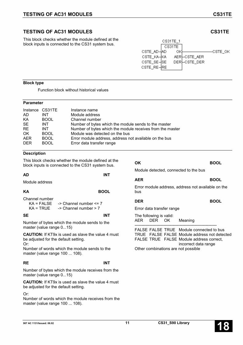
TESTING OF AC31 MODULES CS31TE
907 AC 1131/Issued: 06.02 11 CS31_S90 Library 18
TESTING OF AC31 MODULES CS31TEThis block checks whether the module defined at theblock inputs is connected to the CS31 system bus.
Block typeFunction block without historical values
ParameterInstance CS31TE Instance nameAD INT Module addressKA BOOL Channel numberSE INT Number of bytes which the module sends to the masterRE INT Number of bytes which the module receives from the masterOK BOOL Module was detected on the busAER BOOL Error module address, address not available on the busDER BOOL Error data transfer range
DescriptionThis block checks whether the module defined at theblock inputs is connected to the CS31 system bus.
AD INTModule address
KA BOOLChannel number
KA = FALSE -> Channel number <= 7KA = TRUE -> Channel number > 7
SE INTNumber of bytes which the module sends to themaster (value range 0...15)
CAUTION: If KT9x is used as slave the value 4 mustbe adjusted for the default setting.Or:Number of words which the module sends to themaster (value range 100 ... 108).
RE INTNumber of bytes which the module receives from themaster (value range 0...15)
CAUTION: If KT9x is used as slave the value 4 mustbe adjusted for the default setting.
Or:Number of words which the module receives from themaster (value range 100 ... 108).
OK BOOLModule detected, connected to the bus
AER BOOLError module address, address not available on thebus
DER BOOLError data transfer range
The following is valid:AER DER OK Meaning------------------------------------------------------------FALSE FALSE TRUE Module connected to busTRUE FALSE FALSE Module address not detectedFALSE TRUE FALSE Module address correct,
incorrect data rangeOther combinations are not possible

TESTING OF AC31 MODULES CS31TE
CS31_S90 Library 12 907 AC 1131/Issued: 06.0218
Function call in ILCAL CS31TE1(AD := CSTE_AD,
KA := CSTE_KA, SE := CSTE_SE,RE := CSTE_RE)
LD CS31TE1.AERST CSTE_AERLD CS31TE1.DERST CSTE_DERLD CS31TE1.OKST CSTE_OK
Note: In IL, the function call has to be performed inone line.
Function call in STCS31TE1(AD := CSTE_AD, KA := CSTE_KA,SE := CSTE_SE, RE := CSTE_RE);CSTE_AER:=CS31TE1.AER;CSTE_DER:=CS31TE1.DER;CSTE_OK:=CS31TE1.OK;

907 AC 1131/Issued: 06.02 13 CS31_S90 Library 18
Glossary
BOOLVariables of the type BOOL can have the values TRUE and FALSE. For this, 8 bit memory space are reserved.
DINTDINT belongs to the integer data types.
The different numerical types are responsible for a different numerical range. For integer data types the followingrange limits are valid:
Type Lower limit Upper limit Memory spaceDINT: -2147483648 2147483647 32 Bit
Due to this, it is possible that information are lost during the conversion of greater data types to smaller data types.
DWORDDWORD belongs to the integer data types.
The different numerical types are responsible for a different numerical range. For integer data types the followingrange limits are valid:
Type Lower limit Upper limit Memory spaceDWORD 0 4294967295 32 Bit
Due to this, it is possible that information are lost during the conversion of greater data types to smaller data types.
INTINT belongs to the integer data types.
The different numerical types are responsible for a different numerical range. For integer data types the followingrange limits are valid:
Type Lower limit Upper limit Memory spaceINT: -32768 32767 16 Bit
Due to this, it is possible that information are lost during the conversion of greater data types to smaller data types.
WORDWORD belongs to the integer data types.
The different numerical types are responsible for a different numerical range. For integer data types the followingrange limits are valid:
Type Lower limit Upper limit Memory spaceWORD 0 65535 16 Bit
Due to this, it is possible that information are lost during the conversion of greater data types to smaller data types.

CS31_S90 Library 14 907 AC 1131/Issued: 06.0218
FunctionsFunctions are subroutines which have multiple input parameters and return exactly one result element. Thereturned result can be of an elementary or a derived data type. Due to this, a function may also return an array, astructure, an array of structures and so on.
For the same input parameters, functions always return the same result (they do not have an internal memory).
Therefore, the following rules can derived:
• Within functions, global variables can neither be read nor written.• Within functions, it is not allowed to read or write absolute operands.• Within functions, it is not allowed to call function blocks.
Function blocksFunction blocks are subroutines which can have as much inputs, outputs and internal variables as required. Theyare called by a program or by another function block.
As they can be used several times (with different data records), function blocks (code and interface) can beconsidered as type. When assigning an individual data record (declaration) to the function block, a function blockinstance is generated.
In contrast to functions, function blocks can contain statically local data which are saved from one call to the next.This allows for example to realize counters which may not forget their counter value. I.e. function blocks can havean internal memory.
Functions and function blocks differ in two essential points:
• A function block has multiple output parameters. A function has maximally one output parameter. Note thatthe output parameters of functions and function blocks differ syntactically.
• In contrast to a function, a function block can have an internal memory.
1. Function blocks with historical values (memory):
For function blocks with historical values it has to be observed that instance names may not be defined severaltimes if different data sets should be called.
2. Function blocks without historical values (memory):
For function blocks without historical values only one instance has to be defined for the FB type. This instance canbe used for several calls of the FB (also with different I/O values).
The instance name can be defined without any restrictions. The type is preset and identical to the function blockname.

907 AC 1131/Issued: 06.02 15 CS31_S90 Library 18
Index
CComponents of the CS31 library 2CS31 S90
CS31CO 3
CS31QU 10
CS31TE 11
CS31CO S90 3
CS31QU S90 10
CS31TE S90 11

CS31_S90 Library 16 907 AC 1131/Issued: 06.0218
Software Description Advant Controller 31Intelligent DecentralizedAutomation System
Function Blocksfor the Serial Communication90 Series
Communic.90 Series


907 AC 1131/Issued: 06.02 1 COM_S90 Library 18
Contents
The library for serial communication, 90 series 2PRECONDITIONS FOR THE USE OF THE COM LIBRARY ................................ 2COMPONENTS OF THE COM_S90 LIBRARY .................................. 2
Overview of blocks listed alphabetically according to their call names 3
AUTOMATIC 907 AC 1131 LOGIN IDENTIFICATION INTHE PASSIVE MODE COMAUTOLOGIN .... 4INITIALIZATION OF A SERIAL INTERFACEIN THE "FREE MODE" COMINIT................... 6SENDING OF DATA VIA A SERIAL INTERFACEIN THE "FREE MODE" COMSND................ 12RECEPTION OF DATA VIA A SERIAL INTERFACEIN THE "FREE MODE" COMREC................ 18COMPARISON OF DATA AREASWITH OPTIONAL WILDCARDS DATACMP .............. 24COPYING/MOVING DATA AREAS, INDEXED DATAMOV.............. 27DETERMINING A WILDCARD COMPARISON VALUE IN A DATA TELEGRAM DATAPOS............... 30INITIALIZATION AND CONFIGURATIONOF THE MODBUS INTERFACES MODINIT................. 35OPERATION MODE MODBUS MASTER MODMAST ............. 40RECEIVING A DATA SET FROM THECOMMUNICATION MODULE 07 KP 92 SIREC..................... 53SENDING A DATA SET TO THECOMMUNICATON MODULE 07 KP 92 SISEND .................. 56
Glossary 59
Index 61
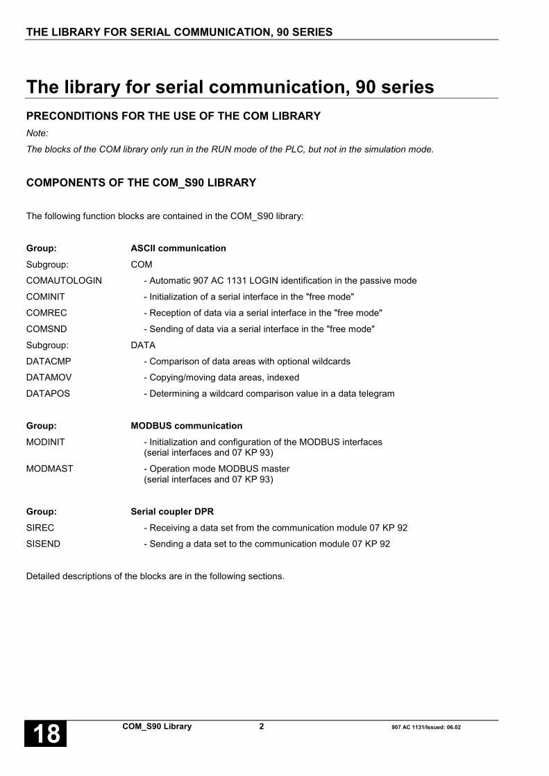
THE LIBRARY FOR SERIAL COMMUNICATION, 90 SERIES
COM_S90 Library 2 907 AC 1131/Issued: 06.0218
The library for serial communication, 90 seriesPRECONDITIONS FOR THE USE OF THE COM LIBRARYNote:
The blocks of the COM library only run in the RUN mode of the PLC, but not in the simulation mode.
COMPONENTS OF THE COM_S90 LIBRARY
The following function blocks are contained in the COM_S90 library:
Group: ASCII communicationSubgroup: COM
COMAUTOLOGIN - Automatic 907 AC 1131 LOGIN identification in the passive mode
COMINIT - Initialization of a serial interface in the "free mode"
COMREC - Reception of data via a serial interface in the "free mode"
COMSND - Sending of data via a serial interface in the "free mode"
Subgroup: DATA
DATACMP - Comparison of data areas with optional wildcards
DATAMOV - Copying/moving data areas, indexed
DATAPOS - Determining a wildcard comparison value in a data telegram
Group: MODBUS communicationMODINIT - Initialization and configuration of the MODBUS interfaces
(serial interfaces and 07 KP 93)
MODMAST - Operation mode MODBUS master(serial interfaces and 07 KP 93)
Group: Serial coupler DPRSIREC - Receiving a data set from the communication module 07 KP 92
SISEND - Sending a data set to the communication module 07 KP 92
Detailed descriptions of the blocks are in the following sections.

OVERVIEW OF BLOCKS LISTED ALPHABETICALLY ACCORDING TO THEIR CALL NAMES
907 AC 1131/Issued: 06.02 3 COM_S90 Library 18
Overview of blocks listed alphabetically according to their call names
Used abbreviations:
FBmV … Function block with historical values
FBoV … Function block without historical values
F … Function
CE Name Type Function Page
COMAUTOLOGIN F Automatic 907 AC 1131 LOGIN identification in the passive mode 4
COMINIT FBmV Initialization of a serial interface in the "free mode" 6
COMREC FboV Reception of data via a serial interface in the "free mode" 18
COMSND FBmV Sending of data via a serial interface in the "free mode" 12
DATACMP F Comparison of data areas with optional wildcards 24
DATAMOV F Copying/moving data areas, indexed 27
DATAPOS F Determining a wildcard comparison value in a data telegram 30
MODINIT FBmV Initialization and configuration of the MODBUS interfaces 35
MODMAST FBmV Operation mode MODBUS master 40
SIREC FboV Receiving a data set from the communication module 07 KP 92 53
SISEND FBmV Sending a data set to the communication module 07 KP 92 56

AUTOMATIC 907 AC 1131 LOGIN IDENTIFICATIONIN THE PASSIVE MODE COMAUTOLOGIN
COM_S90 Library 4 907 AC 1131/Issued: 06.0218
AUTOMATIC 907 AC 1131 LOGIN IDENTIFICATIONIN THE PASSIVE MODE COMAUTOLOGINBy means of the COMAUTOLOGIN function, theautomatic 907 AC 1131 login identification can beactivated for a serial interface (EN = TRUE) ordeactivated (EN = FALSE).
Block typeFunction
ParametersInput Type DescriptionEN BOOL Auto Login identification ON / OFF (TRUE / FALSE)COM INT Interface number, 1 or 2
Return Type DescriptionCOMAUTOLOGIN INT Return value, error
Description see next page

AUTOMATIC 907 AC 1131 LOGIN IDENTIFICATIONIN THE PASSIVE MODE COMAUTOLOGIN
907 AC 1131/Issued: 06.02 5 COM_S90 Library 18
By means of the COMAUTOLOGIN function, theautomatic 907 AC 1131 login identification can beactivated for a serial interface (EN = TRUE) ordeactivated (EN = FALSE). It is recommended only toactivate the login identification, if it is really required.Otherwise, the communication procedures are sloweddown unnecessarily. As a default, the loginidentification is deactivated.
It is also recommended, to keep the EN parameterconstant, i.e. to keep the login identificationpermanently activated or deactivated. In addition, it isuseful to insert the block in the user program directlyafter the initialization block belonging to it (MODINIT orCOMINIT).
The return code of the function is 0(COM_NO_ERROR), if COM = 1 or COM = 2,otherwise 20 (COM_INVALID_COM).
EN BOOLEN FALSE
If EN = FALSE, the COMAUTOLOGIN normally has nofunction. If, however, EN was TRUE before and 907 AC1131 is/was logged in via the serial interface, thefunction reconfigures the interface after terminating theonline session even if EN = FALSE. A renewedautomatic login via the interface is no longer possible,because the automatic login identification wasdeactivated.
EN TRUE
If EN = TRUE, the function compares with every callthe characters received in the meantime with thepattern of the 907 AC 1131 login telegram. Thiscomparison only takes place if the specified interface isrunning in the passive mode and 907 AC 1131 is notlogged in over an other path. If a login telegram isdetected, the interface will be configured as the 907 AC1131 programming access and the login identification isskipped. From now on, it is checked continuouslywhether 907 AC 1131 is still logged in via this interface.If this is no longer the case, the original interfaceparameters are restored and the interface is switchedover again to the passive mode.
COM INTAt the COM input, the number of the serial interface isspecified.
COM = 1: COM1
COM = 2: COM2
COMAUTOLOGIN INTThe return code of the COMAUTOLOGIN is 0, if theCOM input has a valid interface number (1 or 2). If aninvalid number is specified, the function will no longerbe carried out. It only returns the code of 20(COM_INVALID_COM).
Function call in ILLD EN_COMAUTOLOGIN
COMAUTOLOGIN COM_COMAUTOLOGIN
ST RET_COMAUTOLOGIN
Note: In IL, the function call has to be performed inone line.
Function call in STRET_COMAUTOLOGIN =COMAUTOLOGIN
(EN := EN_COMAUTOLOGIN,COM := COM_COMAUTOLOGIN);

INITIALIZATION OF A SERIAL INTERFACE IN THE "FREE MODE" COMINIT
COM_S90 Library 6 907 AC 1131/Issued: 06.0218
INITIALIZATION OF A SERIAL INTERFACE IN THE "FREE MODE" COMINITThe COMINIT function block is used for initialization ofa serial interface employing the sending and receivingfunction blocks COMSND/COMREC. With one project,only one instance of the function block may be usedper interface.
Block typeFunction block with historical values
ParametersInput / Output Type DescriptionInstance COMINIT Instance nameEN BOOL Enable for processing the blockCOM INT Interface number (COM1or COM2)BAUD INT Baud rate (300...19200 bits/s)CH_LEN INT Character length (5, 6, 7 or 8 bits)STOP INT Number of stop bits (1 or 2)PTY INT Parity bit (none, even, odd, always 1 or always 0)RTSCTRL BOOL Direction control (off/on)TLS INT Carrier leading time in milliseconds (0 – 500ms)CDLY INT Carrier lagging time in milliseconds (0 – 100ms)MODE INT Mode of telegram end (terminating character(s), receiving
pause, total time or number of characters)RDY BOOL Readiness for operation of the selected interfaceERNO INT Error number
Description see next page

INITIALIZATION OF A SERIAL INTERFACE IN THE "FREE MODE" COMINIT
907 AC 1131/Issued: 06.02 7 COM_S90 Library 18
The COMINIT function block is used for initialization of a serial interface employing the sending and receivingfunction blocks COMSND/COMREC. With one project, only one instance of the function block may be used perinterface.
The values of the input parameters come into effect with a FALSE->TRUE edge at the EN input. As long as the ENinput remains TRUE, the interface is run in the "free mode" then. The outputs indicate errors which occur duringinitialization and current operation. If EN = FALSE, the interface is free for other modes.
The inputs can neither be duplicated nor negated/inverted.
Telegram end identifierThe telegram end identifier is used for identifying received telegrams or signaling the telegram termination whensending data to the counter-station. Since the kind of telegram termination differs from device to device (e.g. usinga defined ASCII character or an agreed number of characters), it can be set at the MODE input which event shallbe interpreted as the telegram termination. This agreement is project-globally valid for all sending and receivingoperations via an interface. The values belonging to it can be defined separately for every sending or receivingoperation. In the following explanations, it is assumed that the input buffer does not overflow, i.e. the telegram endevent occurs before 256 bytes were received and read. Otherwise, an error message is generated (see alsoCOMREC block).
MODE = 0 NO TELEGRAM END IDENTIFICATIONSending Receiving
no effect All received characters are output immediately.
MODE = 1 TELEGRAM END = SPECIAL CHARACTERSending Receiving
The end-of-telegram character, specified at theEND_CH input of a COMSND sending block, isautomatically added on the telegram last.
The special character is defined at the END inputof a COMREC receiving block. If the blockreceives this character, the telegram isrecognized to be complete. The telegram isoutput together with the end-of-telegramcharacter.
MODE = 2 TELEGRAMMENDE = TELEGRAM LENGTHSending Receiving
no effect The number of characters is specified at the ENDinput of a COMREC receiving block. Thetelegram is recognized to be complete when thegiven number of characters has been received.The telegram is output then.
MODE = 3 TELEGRAM END = TIME INTERVALSending Receiving
no effect The time interval is specified in ms at the ENDinput of a COMREC receiving block. When thetime interval has elapsed, all characters receivedup to this moment are output.
INITIALIZATION OF A SERIAL INTERFACE IN THE "FREE MODE" COMINIT
COM_S90 Library 8 907 AC 1131/Issued: 06.0218
MODE = 4 TELEGRAM END = PAUSESending Receiving
no effect The pause length is specified at the END input ofthe receiving block. The pause monitoring startswith the reception of the first character and ends,when a pause of the specified length wasrecognized. All received characters are outputnow.
Use of modemsThe COMINIT block takes the special features of modems, interface converters and repeaters into account. If thesedevices are used at a serial interface operating in the "free mode", their possibly supported compressingmechanisms must be deactivated. For more information see also the manuals of the corresponding devices.
In order to set the transmission direction, some repeaters, modems or interface converters require a control signal.This direction control can be switched on/off with the RTSCTRL input.
In addition, some devices need a leading time (settling time) in order to stabilize their carrier signal. Only when thistime has elapsed, the devices are ready for data transmission in sending direction. This settling time can be set atthe TLS input.
Some devices require that the carrier signal in sending direction is kept stable for a while after data transmission.Only when this lagging time has elapsed, a complete data transmission is guaranteed and the devices are ready fordata transmission in the opposite direction. The lagging time can be specified at the CDLY input.
Note: Leading and lagging times must be matched between all communication partners connected to the samedata transmission line.
EN BOOL
EN FALSE → TRUE:
With a FALSE->TRUE edge, the values of the inputscome into effect. It is recommended, to set the inputs toconstant values. The block tries to configure the COMinterface (specified at the COM input) with the values ofthe input parameters. If this configuration procedurefails, the ERNO output indicates an error. The currentsetting remains unchanged then.
EN TRUE:
As long as no error occurred during initialization (ERNOoutput), the interface is activated in the "free mode". If907 AC 1131 logs-in temporarily, the block is lockedduring the online session. After logging out 907 AC1131 and after the following automatic re-initialization,the block returns to its normal function. The enableinput EN of the block must still be TRUE.
EN TRUE → FALSE:
The interface is deactivated. It can be used for otherapplications. The RDY output is set to FALSE. TheERNO output is set to COM_NO_ERROR.
EN FALSE
The block is not processed. The interface is notoperated in the "free mode".
COM INTAt the COM input, the number of the serial interface isspecified.
COM = 1: COM1
COM = 2: COM2
BAUD INTAt the BAUD input, the data transmission speed is setin bits per second. The following settings are possible:
300, 1200, 2400, 4800, 9600, 14400 or 19200 bits/s
INITIALIZATION OF A SERIAL INTERFACE IN THE "FREE MODE" COMINIT
907 AC 1131/Issued: 06.02 9 COM_S90 Library 18
CH_LEN INTAt the CH_LEN input, the character transmission lengthis specified in bits. The following settings are possible:
5, 6, 7 or 8 bits per character
Note: If the character length is set to 5 bits(CH_LEN = 5) and 2 stop bits are set at the same time,the UART configures itself to 1.5 stop bits.
STOP INTAt the STOP input, the number of stop bits percharacter is given. The following settings are possible:
1 or 2 stop bits per character
PTY INTAt the PTY input, the parity bit type is defined. Thesettable parity (PTY) is encoded in the following way:
PTY = 0: No parity bit
PTY = 1: Odd parity. The number of characterbits owing 1 is complemented so that the total numberis odd.
PTY = 2: Even parity. The number of characterbits owing 1 is complemented so that the total numberis even.
PTY = 3 Parity bit is always 1
PTY = 4 Parity bit is always 0
RTS_CTRL BOOLAt the RTSCTRL input, it is specified whether thesynchronization between the interface and theconnected device(s) is to be carried out with the RTSdirection control signal.
RTSCTRL = TRUE RTS is used
RTSCTRL = FALSE RTS is unused
With the activated RTS mechanism(RTSCTRL = TRUE), the required control signals areautomatically generated by the interface.
TLS INTAt the TLS input, the carrier leading time (settling time)is specified in ms (0...500 ms).
The TLS input is only processed, if RTS_CTRL =TRUE. The realization of the leading time depends onthe cycle time of the task in which the COMINIT blockis processed. Under worst-case conditions, the realleading time can have a deviation of (one task cycle- 1 ms) referred to the specification.
CDLY INTAt the CDLY input, the carrier lagging time is specifiedin ms (0...100 ms).
The CDLY input is only processed, if RTS_CTRL =TRUE. The realization of the leading time depends onthe cycle time of the task in which the COMINIT blockis processed. Under worst-case conditions, the reallagging time can have a deviation of (one task cycle- 1 ms) referred to the specification.
MODE INTAt the MODE input, the type of the telegram endidentification is set. The values belonging to it can bedefined at the corresponding sending and receivingblocks. MODE is encoded as follows:
MODE = 0 no telegram end identification
MODE = 1 Telegram end by special character
MODE = 2 Telegram end by telegram length
MODE = 3 Telegram end by time interval
MODE = 4 Telegram end by receiving pause(character timeout)
RDY BOOLAt the READY output, it is indicated that the interface isready for operation. RDY has always to be consideredtogether with the ERNO output.

INITIALIZATION OF A SERIAL INTERFACE IN THE "FREE MODE" COMINIT
COM_S90 Library 10 907 AC 1131/Issued: 06.0218
ERNO INTThe ERNO output indicates errors occurred. The following table explains the meaning of the ERNO codes:
ERNO Meaning
0 COM_NO_ERROR No error occurred. The interface is operated asconfigured.
20 COM_INVALID_COM Invalid value at the COM input
51 COM_INVALID_BAUD_RATE Invalid baud rate at the BAUD input
52 COM_INVALID_PARITY Invalid parity at the PTY input
53 COM_INVALID_NUM_STOP_BITS Invalid number of stop bits at the STOP input
54 COM_TLS_OVERRIDE Invalid carrier leading time at the TLS input
55 COM_CDLY_OVERRIDE Invalid carrier lagging time at the CDLY input
56 COM_CDLY_EXCEEDS_TLS Carrier lagging time is greater than carrier leadingtime
59 COM_6_8_DISCONNECT No connection between the pins 6 and 8 of the COMinterface. If currently no serial programminginterface is defined for 907 AC 1131, the COMinterface is temporarily set up as a programminginterface.
62 COM_RECONFIGURED Interface was reconfigured with other Init blocks(e.g. MODINIT re-configured). It is no longeroperated in the way set with COMINIT.
65 COM_AC1131_LOGIN 907 AC 1131 is logged in via this interface.
70 COM_INVALID_CHAR_LENGTH Invalid number of bits (or characters) specified at theCH_LEN input
71 COM_INVALID_TELEGRAM_END Invalid end identification at the MODE input
65535 COM_AC1131_REMOTE_ACCESS 907 AC 1131 is temporarily logged in

INITIALIZATION OF A SERIAL INTERFACE IN THE "FREE MODE" COMINIT
907 AC 1131/Issued: 06.02 11 COM_S90 Library 18
Function call in ILCAL INIT_COM(EN := EN_COMINIT,COM := COM_COMINIT,BAUD := BAUD_COMINIT,CH_LEN := CH_LEN_COMINIT,STOP := STOP_COMINIT,PTY := PTY_COMINIT,RTSCTRL := RTSCTRL_COMINIT,TLS := TLS_COMINIT,CDLY := CDLY_COMINIT,MODE := MODE_COMINIT)
LD INIT_COM.RDY
ST RDY_COMINIT
LD INIT_COM.ERNO
ST ERNO_COMINIT
Note: In IL, the function call has to be performed inone line.
Function call in STINIT_COM(EN := EN_COMINIT,COM := COM_COMINIT,BAUD := BAUD_COMINIT,CH_LEN := CH_LEN_COMINIT,STOP := STOP_COMINIT,PTY := PTY_COMINIT,RTSCTRL := RTSCTRL_COMINIT,TLS := TLS_COMINIT,CDLY := CDLY_COMINIT,MODE := MODE_COMINIT);
RDY_COMINIT := INIT_COM.RDY;
ERNO_COMINIT := INIT_COM.ERNO;

SENDING OF DATA VIA A SERIAL INTERFACE IN THE "FREE MODE" COMSND
COM_S90 Library 12 907 AC 1131/Issued: 06.0218
SENDING OF DATA VIA A SERIAL INTERFACE IN THE "FREE MODE" COMSNDThe COMSND block is used for sending data via aserial interface. The number of COMSND blocks usedin the same project is not limited. It is also possible touse the blocks in different user tasks. A sendingoperation is started with a FALSE->TRUE edge at theEN input. Specifying the memory address of the data tobe sent instead of the values itself makes a telegramstructure possible without any format restrictions. Thelength of a data block to be sent is not limited. Since,however, the data only can be sent as long as thesending buffer has enough free space, it isrecommended to copy only data blocks to the sendingbuffer with a maximum of 256 bytes in size. By usingCOMSND blocks adjacent to one another and ignoringtheir RDY outputs it is also possible to generate longertelegrams if necessary.
Block typeFunction block with historical value
ParametersInput / Output Type DescriptionInstance COMSND Instance nameEN BOOL Enable sending with a FALSE -> TRUE edgeCOM INT Interface number (COM1or COM2)DATA DWORD Memory address of data to be sent via ADR operatorLEN INT Length of data to be sent as of the DATA address in bytesEND_CH INT Value for telegram end, depending on the set telegram mode
at the COMINIT input (MODE):Termination character to be added at the end of dataTelegram pause unimportantTime unimportantNumber of characters unimportant
RDY BOOL Sending buffer is emptyERNO INT Error number
Description
The COMSND block is used for sending data via aserial interface. The number of COMSND blocksused in the same project is not limited. It is alsopossible to use the blocks in different user tasks. Asending operation is started with a FALSE->TRUEedge at the EN input. Specifying the memory addressof the data to be sent instead of the values itselfmakes a telegram structure possible without any
format restrictions. The length of a data block to besent is not limited. Since, however, the data only canbe sent as long as the sending buffer has enoughfree space, it is recommended to copy only datablocks to the sending buffer with a maximum of 256bytes in size. By using COMSND blocks adjacent toone another and ignoring their RDY outputs it is alsopossible to generate longer telegrams if necessary.
The inputs can neither be duplicated nor negated/inverted.

SENDING OF DATA VIA A SERIAL INTERFACE IN THE "FREE MODE" COMSND
907 AC 1131/Issued: 06.02 13 COM_S90 Library 18
Telegram lengthThe maximum length of a sending telegram can be controlled by evaluating the RDY output. RDY = TRUEindicates an empty sending buffer. If a sending process always is started with RDY = TRUE, a single telegram issent per COMSND each. If RDY is ignored, data streams of any length are possible (theoretically). See also thefigure below.
If it was planned with COMINIT direction control (and carrier leading and lagging signals), the carrier lagging time isautomatically adjusted, i.e. the carrier lagging time is triggered when the sending buffer has no more data to besent.
Sendingbuffer
COMSND
COMSND ignores RDY
COMSNDData to be sent
in buffer
Sendingbuffer
Data to be sentin buffer
Real telegram endblock 1 + block 2
Theor. telegram endblock 1
Real telegram end block 1 + block 2
Telegram startblock 1 (+ block 2)
Theor. telegram endblock 2
Theor. telegram startblock 2

SENDING OF DATA VIA A SERIAL INTERFACE IN THE "FREE MODE" COMSND
COM_S90 Library 14 907 AC 1131/Issued: 06.0218
Sendingbuffer empty
COMINIT
COMSND
Sending datain buffer
Bufferinterrog.
Bufferinterrogation
RTS OFF
RTS ON
Carrier leading time Data transmission
Enablesending
Bufferinterrog.
Disablesending
Carrier lagging time
RTS ON RTS ON
RTS OFF
Sending datain buffer
Bufferinterrogation
Sendingbuffer empty
COMINIT
COMSND
Sending datain buffer
Bufferinterrog.
Bufferinterrogation
RTS OFF
RTS ON
Carrier leading time Data transmission
Enablesending
Bufferinterr.
Disablesending
Carrier lagging time
RTS ON RTS ON
RTS OFF
Sending datain buffer
Bufferinterrog.
Bufferinterrog.
COMSND is waiting for RDY = TRUE
COMSND ignores RDY
EN BOOLEN FALSE->TRUE
With a FALSE->TRUE edge at the EN input, it is triedto send the telegram specified by the block inputs. If anerror is detected while checking the input parameters,this is indicated at the ERNO output. In case of anerror, no data transmission takes is carried out.
Independent of the status of the EN input, the block isdisabled as long as 907 AC 1131 is logged intemporarily via the COM interface. After logging out907 AC 1131 and the following automatic re-initialization of the interface, the block returns to thenormal function. The interface must be still active(COMINT EN = TRUE).
COM INTAt the COM input, the number of the serial interface isspecified.
COM = 1: COM1
COM = 2: COM2
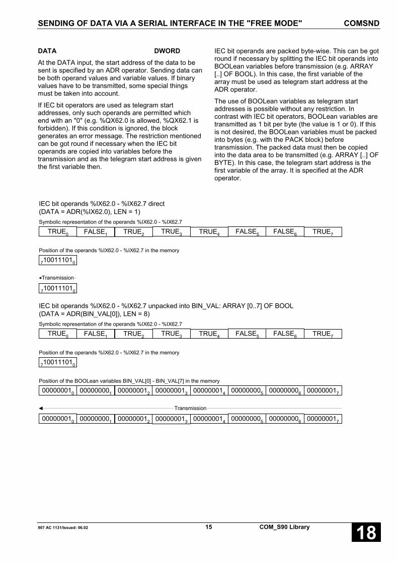
SENDING OF DATA VIA A SERIAL INTERFACE IN THE "FREE MODE" COMSND
907 AC 1131/Issued: 06.02 15 COM_S90 Library 18
DATA DWORDAt the DATA input, the start address of the data to besent is specified by an ADR operator. Sending data canbe both operand values and variable values. If binaryvalues have to be transmitted, some special thingsmust be taken into account.
If IEC bit operators are used as telegram startaddresses, only such operands are permitted whichend with an "0" (e.g. %QX62.0 is allowed, %QX62.1 isforbidden). If this condition is ignored, the blockgenerates an error message. The restriction mentionedcan be got round if necessary when the IEC bitoperands are copied into variables before thetransmission and as the telegram start address is giventhe first variable then.
IEC bit operands are packed byte-wise. This can be gotround if necessary by splitting the IEC bit operands intoBOOLean variables before transmission (e.g. ARRAY[..] OF BOOL). In this case, the first variable of thearray must be used as telegram start address at theADR operator.
The use of BOOLean variables as telegram startaddresses is possible without any restriction. Incontrast with IEC bit operators, BOOLean variables aretransmitted as 1 bit per byte (the value is 1 or 0). If thisis not desired, the BOOLean variables must be packedinto bytes (e.g. with the PACK block) beforetransmission. The packed data must then be copiedinto the data area to be transmitted (e.g. ARRAY [..] OFBYTE). In this case, the telegram start address is thefirst variable of the array. It is specified at the ADRoperator.
IEC bit operands %IX62.0 - %IX62.7 direct(DATA = ADR(%IX62.0), LEN = 1)
7100111010
Transmission
TRUE0 FALSE1 TRUE2 TRUE3 TRUE4 FALSE5 FALSE6 TRUE7
Symbolic representation of the operands %IX62.0 - %IX62.7
7100111010
Position of the operands %IX62.0 - %IX62.7 in the memory
IEC bit operands %IX62.0 - %IX62.7 unpacked into BIN_VAL: ARRAY [0..7] OF BOOL(DATA = ADR(BIN_VAL[0]), LEN = 8)
000000010 000000001 000000012 000000013 000000014 000000005 000000006 000000017
TRUE0 FALSE1 TRUE2 TRUE3 TRUE4 FALSE5 FALSE6 TRUE7
Symbolic representation of the operands %IX62.0 - %IX62.7
7100111010
Position of the operands %IX62.0 - %IX62.7 in the memory
000000010 000000001 000000012 000000013 000000014 000000005 000000006 000000017
Transmission
Position of the BOOLean variables BIN_VAL[0] - BIN_VAL[7] in the memory

SENDING OF DATA VIA A SERIAL INTERFACE IN THE "FREE MODE" COMSND
COM_S90 Library 16 907 AC 1131/Issued: 06.0218
BOOLean variables in BIN_VAL: ARRAY [0..7] OF BOOL direct(DATA = ADR(BIN_VAL[0]), LEN = 8)
000000010 000000001 000000012 000000013 000000014 000000005 000000006 000000017
Transmission
TRUE0 FALSE1 TRUE2 TRUE3 TRUE4 FALSE5 FALSE6 TRUE7
Symbolic representation of the variables BIN_VAL[0] - BIN_VAL[7]
000000010 000000001 000000012 000000013 000000014 000000005 000000006 000000017
Position of the BOOLean variables BIN_VAL[0] - BIN_VAL[7] in the memory
BOOLean variables in BIN_VAL: ARRAY [0..7] OF BOOL packed in BIN_PACK: BYTE(DATA = ADR(BIN_PACK), LEN = 1)
7100111010
7100111010
TRUE0 FALSE1 TRUE2 TRUE3 TRUE4 FALSE5 FALSE6 TRUE7
Symbolic representation of the variables BIN_VAL[0] - BIN_VAL[7]
000000010 000000001 000000012 000000013 000000014 000000005 000000006 000000017
Position of the BOOLean variables BIN_VAL[0] - BIN_VAL[7] in the memory
Position of the BYTE variables BIN_PACK in the memory
Transmission
= 157
LEN INTAt the LEN input, the length of data to be sent isspecified in bytes, without an possibly existing endcharacter. The LEN value comes into effect with aFALSE->TRUE edge at the EN input.
END_CH INTThe value of the telegram end character is specified atthe END_CH input. This character is added to thesending data. END_CH is only evaluated, if at theCOMINIT initialization block the telegram end identifiermode was planned with "Telegram End Character" forthe corresponding interface (MODE = 1). For END_CH,
only values between 0 and 255 are valid. END_CHcomes into effect with a FALSE->TRUE edge at the ENinput. If necessary, the end of telegram character canbe varied from telegram to telegram in this way.
RDY BOOLIndependent of the status of the EN input, the RDYoutput indicates whether the sending buffer isabsolutely empty (RDY = TRUE) or not (RDY =FALSE). A precondition is that the interface wassuccessfully configured as a "free interface" before. Italso must be active. RDY has always to be consideredtogether with the ERNO output.
SENDING OF DATA VIA A SERIAL INTERFACE IN THE "FREE MODE" COMSND
907 AC 1131/Issued: 06.02 17 COM_S90 Library 18
ERNO INTThe ERNO output indicates occurred errors. The output values are encoded as follows:
ERNO Meaning
0 COM_NO_ERROR No error. Interface is operated as configured.
15 COM_INIT_ERROR Initialization error. The interface has not beeninitialized correctly.
20 COM_INVALID_COM Invalid value at the COM input.
59 COM_6_8_DISCONNECT No connection between the pins 6 and 8 of theCOM interface.
63 COM_DIFFERENT_CONFIG Interface is not configured in the "free mode".
69 COM_INVALID_DATA_ADDRESS The address at DATA is invalid
71 COM_INVALID_TELEGRAM_END Invalid end identifier. End character planned.END_CH is less than 0 or greater than 255
72 COM_TELEGRAM_SIZE_OVERRIDE LEN is less than 0 or greater than the freebuffer area
65535 COM_AC1131_REMOTE_ACCESS 907 AC 1131 temporarily logged-in.
Function call in ILLD DATA_COMSND
ADR
ST SEND_COM.DATA
CAL SEND_COM(EN := EN_COMSND,COM := COM_COMSND,LEN := LEN_COMSND,END_CH := END_CH_COMSND)
LD SEND_COM.RDY
ST RDY_COMSND
LD SEND_COM.ERNO
ST ERNO_COMSND
Note: In IL, the function call has to be performed inone line.
Function call in STSEND_COM(EN := EN_COMSND,COM := COM_COMSND,DATA := ADR(DATA_COMSND),LEN := LEN_COMSND,END_CH := END_CH_COMSND);
RDY_COMSND := SEND_COM.RDY;
ERNO_COMSND := SEND_COM.ERNO;

RECEPTION OF DATA VIA A SERIAL INTERFACE IN THE "FREE MODE" COMREC
COM_S90 Library 18 907 AC 1131/Issued: 06.0218
RECEPTION OF DATA VIA A SERIAL INTERFACE IN THE "FREE MODE" COMRECThe COMREC function block is used for receiving datafrom a serial interface in the "free mode". The numberof COMREC blocks used in the same project is notlimited. It is also possible to use the blocks in differentuser tasks. It is important that the blocks must beinterlocked to one another, i.e. only one block may beactive at the same time. In order to avoid that telegramparts are lost or evaluated incorrectly or not at all, anactivity change between two COMREC blocks mayonly be carried out when the block to be deactivatedhas signalized that it has completely evaluated thereceived telegram (RDY = TRUE).
Here it must be made sure that at first all instances ofthe block are deactivated before the activity changecan be performed. In order to avoid competenceconflicts, it is strongly recommended to use only oneCOMREC block within one project.
Block typeFunction block without historical values
ParametersInput / Output Type DescriptionInstance COMREC Instance nameEN BOOL Enable sending by a FALSE -> TRUE edgeCOM INT Interface number (COM1or COM2)DATA DWORD Memory address for the receiving data via ADR operatorEND INT Value for telegram end identification, depending on the set
telegram mode at the COMINIT input (MODE):Termination character value of the end characterTelegram pause Minimum length of the receiving
pause in msTime Time value in ms
(as of last receiving)Number of characters Telegram length in No. of characters
RDY BOOL Data receivedERNO INT Error numberLEN INT Length of the valid receiving data as of address DATA in bytes
DescriptionThe COMREC function block is used for receiving data from a serial interface in the "free mode". The number ofCOMREC blocks used in the same project is not limited. It is also possible to use the blocks in different user tasks.It is important that the blocks must be interlocked to one another, i.e. only one block may be active at the sametime. In order to avoid that telegram parts are lost or evaluated incorrectly or not at all, an activity change betweentwo COMREC blocks may only be carried out when the block to be deactivated has signalized that it hascompletely evaluated the received telegram (RDY = TRUE).
Here it must be made sure that at first all instances of the block are deactivated before the activity change can beperformed. In order to avoid competence conflicts, it is strongly recommended to use only one COMREC blockwithin one project.

RECEPTION OF DATA VIA A SERIAL INTERFACE IN THE "FREE MODE" COMREC
907 AC 1131/Issued: 06.02 19 COM_S90 Library 18
Since the block enable input EN works level-dependent and not edge-triggered, the block checks the values at theinputs with every call for validity, as long as EN = TRUE.
Specifying a memory address for the receiving data makes a telegram structure possible without any formatrestrictions. The length of a receiving data block is limited to a maximum of 256 bytes. It is indicated at the LENoutput.
Note: During the planning phase, it must be kept in mind that there is enough memory space free for storing thereceiving data, (e.g. ARRAY [1..256] OF BYTE). The memory space begins at the DATA address.
If a valid receiving telegram exists in the memory area as of DATA, this is always indicated by RDY = TRUE. Thebehavior of RDY as a function of time is here dependent on the ratio of the task cycle-time related to the rate ofincoming telegrams. If receiving telegrams come in in shorter distances than the cycle time, RDY is TRUE in everycycle. If the distance between the telegrams is longer than the task cycle time, at first RDY indicates the receptionof a telegram by a FALSE->TRUE edge, then (beginning with the next cycle) RDY goes back to FALSE for acertain number of cycles. After that, the reception of another telegram is indicated by a new FALSE->TRUE edge.
Important: It is strongly recommended to evaluate RDY level-dependent and not edge-triggered.
Cycle1 2 3 4 5
CO
MR
EC
Rec
eptio
n of
ate
legr
am v
alid
for
CO
MR
EC
RDY
CO
MR
EC
CO
MR
EC
CO
MR
EC
Rec
eptio
n of
ate
legr
am v
alid
for
CO
MR
EC
Rec
eptio
n of
ate
legr
am v
alid
for
CO
MR
ECIndependent of the status at the EN input, the block is disabled as long as 907 AC 1131 is logged in temporarily.After logging out 907 AC 1131 and the following re-initialization of the interface, the block returns to its normalfunction. The interface must be still active (COMINT.EN = TRUE).
The inputs can neither be duplicated nor negated/inverted.
Receiving errorsIf receiving errors occur, they will be recognized and indicated by the block. The block detects overflow, parity andframing errors. If at least one of these errors has occurred, the block deletes the receiving buffer.
In this case, the interface parameters of the communication partners must be checked (for e.g. baud rate, characterlength, number of stop bits and parity).
TimesIf the telegram end identifier was selected as "time interval" (MODE = 3) or as "receiving pause" (MODE = 4), thetimes are monitored by the block. In MODE = 3, the monitoring time defined at END is triggered cyclically. Theruntime system counts up the time in steps of 5 ms. Because of this, it is possible that the real waiting time islonger than the defined time (by up to 5 ms plus the cycle time of the task which called the block). The receivingpause identification, however, is carried out with a resolution of 1 millisecond.

RECEPTION OF DATA VIA A SERIAL INTERFACE IN THE "FREE MODE" COMREC
COM_S90 Library 20 907 AC 1131/Issued: 06.0218
EN BOOLEN FALSE
If EN = FALSE, the block is not operated.
EN TRUE
If EN = TRUE, the block checks the receiving buffer for a telegram (end identification) specified at the block inputswith every call.
COM INTAt the COM input, the number of the serial interface is specified.
COM = 1: COM1
COM = 2: COM2
DATA DWORDAt the DATA input, the start address for storing the receiving data is specified by an ADR operator. Received datacan be stored in the operand area as well as in variables. When binary values are received, some special thingsmust be considered.
If IEC bit operators are used as memory address, only such operands are permitted which end with an "0" (e.g.%QX62.0 is allowed, %QX62.1 is forbidden). If this condition is ignored, the block generates an error message.
When a receiving telegram is stored in the IEC bit operand area, it must be taken into account that a received bytecontains 8 bit operands. If, however, a received byte is stored in a BOOLean variable, this variable is FALSE (bytevalue = 0) or TRUE (byte value unequal 0).
Byte stored in 8 IEC bit operands %MX62.0 - %MX62.7 direct(DATA = ADR(%MX62.0))
Byte stored in a BOOLean variable BIN: BOOL(DATA = ADR(BIN))
TRUE
Received byte
7100111010
TRUE0 FALSE1 TRUE2 TRUE3 TRUE4 FALSE5 FALSE6 TRUE7
END INTThe value for the telegram end identification is specified at the END input. The evaluation of END is performeddependent on the MODE set at COMINIT. The value at END is evaluated with every block call. So it is possible tochange the value at any time, even during a reception process.
If MODE = 0, END is ignored. Received characters are output immediately.
If MODE = 1 (telegram end = special character), END is to be set to the character which marks a telegram end. Inthis case, END must have a value from 1 to 255.
If MODE = 2 (telegram end by telegram length), END is to be set to the number of expected bytes. END must havea value from 1 to 256.
If MODE = 3 (telegram end by time interval), END must be specified in milliseconds. After this time has elapsed, allreceived characters are output. Allowed values: 10 to 10,000 ms. The time monitoring is triggered again with everynew cycle.
If MODE = 4 (telegram end by receiving pause / character timeout), END must be specified with the maximumallowed receiving pause between two characters in ms. Valid values: 1 to 500 ms. The time monitoring is triggeredrepeatedly with every received character.
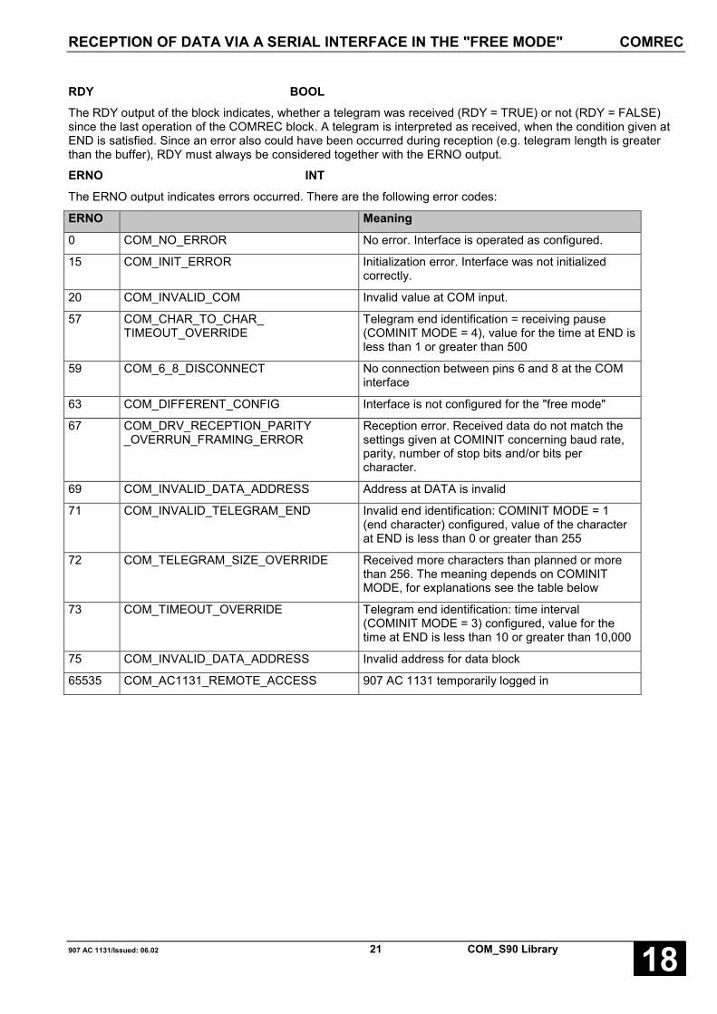
RECEPTION OF DATA VIA A SERIAL INTERFACE IN THE "FREE MODE" COMREC
907 AC 1131/Issued: 06.02 21 COM_S90 Library 18
RDY BOOLThe RDY output of the block indicates, whether a telegram was received (RDY = TRUE) or not (RDY = FALSE)since the last operation of the COMREC block. A telegram is interpreted as received, when the condition given atEND is satisfied. Since an error also could have been occurred during reception (e.g. telegram length is greaterthan the buffer), RDY must always be considered together with the ERNO output.
ERNO INTThe ERNO output indicates errors occurred. There are the following error codes:
ERNO Meaning
0 COM_NO_ERROR No error. Interface is operated as configured.
15 COM_INIT_ERROR Initialization error. Interface was not initializedcorrectly.
20 COM_INVALID_COM Invalid value at COM input.
57 COM_CHAR_TO_CHAR_TIMEOUT_OVERRIDE
Telegram end identification = receiving pause(COMINIT MODE = 4), value for the time at END isless than 1 or greater than 500
59 COM_6_8_DISCONNECT No connection between pins 6 and 8 at the COMinterface
63 COM_DIFFERENT_CONFIG Interface is not configured for the "free mode"
67 COM_DRV_RECEPTION_PARITY_OVERRUN_FRAMING_ERROR
Reception error. Received data do not match thesettings given at COMINIT concerning baud rate,parity, number of stop bits and/or bits percharacter.
69 COM_INVALID_DATA_ADDRESS Address at DATA is invalid
71 COM_INVALID_TELEGRAM_END Invalid end identification: COMINIT MODE = 1(end character) configured, value of the characterat END is less than 0 or greater than 255
72 COM_TELEGRAM_SIZE_OVERRIDE Received more characters than planned or morethan 256. The meaning depends on COMINITMODE, for explanations see the table below
73 COM_TIMEOUT_OVERRIDE Telegram end identification: time interval(COMINIT MODE = 3) configured, value for thetime at END is less than 10 or greater than 10,000
75 COM_INVALID_DATA_ADDRESS Invalid address for data block
65535 COM_AC1131_REMOTE_ACCESS 907 AC 1131 temporarily logged in

RECEPTION OF DATA VIA A SERIAL INTERFACE IN THE "FREE MODE" COMREC
COM_S90 Library 22 907 AC 1131/Issued: 06.0218
LEN INTThe LEN output indicates the length of the received data in bytes inclusive the possibly existing end character. LENis only valid if RDY = TRUE. LEN has always to be considered together with the ERNO output. ERNO indicateswhether the telegram is genuine and complete according to the settings (MODE, END), see the table below).
MODE Parameters / Status Meaning
0,1,2,3,4
RDY = FALSEERNO = 0LEN = 0
No telegram detected (yet) which meets theconditions concerning the telegram endidentification
0 RDY = TRUEERNO = 0LEN = Number of characters
There are between 1 and 256 characters in thereceiving buffer.
The telegram is stored as of the DATA address.
0 RDY = TRUEERNO = 72LEN = 256
More than 256 characters in the receiving buffer.
The first 256 bytes of the telegram are stored as ofthe DATA address. The left characters stay inbuffer. They are picked up in the next cycle.
1 RDY = TRUEERNO = 0LEN = Number of characters
(incl. end character)
End character END received and 1 to 256characters (incl. end character) present inreceiving buffer
The telegram inclusive the end character is storedas of the DTA address.
1 RDY = TRUEERNO = 72LEN = 256
End character END was not received, but there are256 or more characters in the buffer.
The first 256 bytes of the telegram are stored as ofthe DATA address. The left characters stay inbuffer at first. They can be picked up in thefollowing cycles.
2 RDY = TRUEERNO = 0LEN = Number of characters (= END)
Exactly the number of characters are received asspecified at END.
The telegram is stored as of the DTA address.
2 RDY = TRUEERNO = 72LEN = Number of characters (= END)
More characters than specified at END werereceived. The first Number of Characters Byte ofthe telegram are stored as of the DATA address.The left characters stay in buffer at first. They canbe picked up in the following cycles.
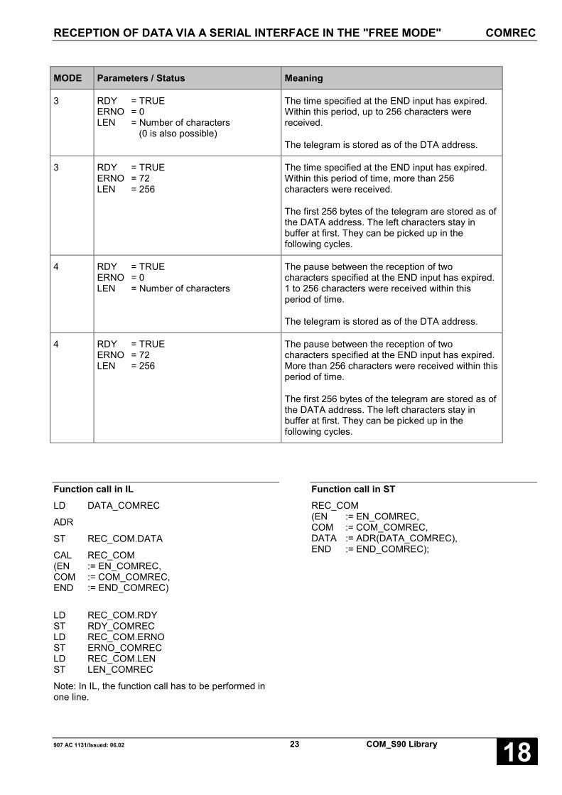
RECEPTION OF DATA VIA A SERIAL INTERFACE IN THE "FREE MODE" COMREC
907 AC 1131/Issued: 06.02 23 COM_S90 Library 18
MODE Parameters / Status Meaning
3 RDY = TRUEERNO = 0LEN = Number of characters
(0 is also possible)
The time specified at the END input has expired.Within this period, up to 256 characters werereceived.
The telegram is stored as of the DTA address.
3 RDY = TRUEERNO = 72LEN = 256
The time specified at the END input has expired.Within this period of time, more than 256characters were received.
The first 256 bytes of the telegram are stored as ofthe DATA address. The left characters stay inbuffer at first. They can be picked up in thefollowing cycles.
4 RDY = TRUEERNO = 0LEN = Number of characters
The pause between the reception of twocharacters specified at the END input has expired.1 to 256 characters were received within thisperiod of time.
The telegram is stored as of the DTA address.
4 RDY = TRUEERNO = 72LEN = 256
The pause between the reception of twocharacters specified at the END input has expired.More than 256 characters were received within thisperiod of time.
The first 256 bytes of the telegram are stored as ofthe DATA address. The left characters stay inbuffer at first. They can be picked up in thefollowing cycles.
Function call in ILLD DATA_COMREC
ADR
ST REC_COM.DATA
CAL REC_COM(EN := EN_COMREC,COM := COM_COMREC,END := END_COMREC)
LD REC_COM.RDYST RDY_COMRECLD REC_COM.ERNOST ERNO_COMRECLD REC_COM.LENST LEN_COMREC
Note: In IL, the function call has to be performed inone line.
Function call in STREC_COM(EN := EN_COMREC,COM := COM_COMREC,DATA := ADR(DATA_COMREC),END := END_COMREC);

COMPARISON OF DATA AREAS WITH OPTIONAL WILDCARDS DATACMP
COM_S90 Library 24 907 AC 1131/Issued: 06.0218
COMPARISON OF DATA AREAS WITH OPTIONAL WILDCARDS DATACMPThe DATACMP function compares two data areas. Asan option, wildcards can be used. DATACMP worksindependent of the data format at the inputs DATA andCOMP.
Block typeFunction
ParametersInput Type DescriptionEN BOOL Enable for block processingDATA DWORD Address of the received telegram to be compared (by ADR
operator)COMP DWORD Address of the comparison telegram (by ADR operator)LEN INT Number of bytes to be comparedDEF INT Wildcard (-1 no wildcard, otherwise 0<= DEF <= 255)
Return Type DescriptionDATACMP INT Return code, result of comparison
DescriptionThe DATACMP function compares two data areas. Asan option, wildcards can be used. DATACMP worksindependent of the data format at the inputs DATA andCOMP.
EN BOOLEN FALSE
With EN = FALSE, the function is not performed.
EN TRUE
If EN = TRUE, the function compares with every callthe data areas specified at DATA and COMP with alength given at LEN taking into consideration a wildcardif exists at DEF.
DATA DWORDThe DATA input specifies the start address (given byan ADR operator) of the data to be compared. The datacan be stored in the operand area or as variables. Ifbinary values are used, some special things must betaken into account.
If IEC bit operators are used as data addresses, onlysuch operands are permitted which end with an "0"(e.g. %QX62.0 is allowed, %QX62.1 is forbidden). Ifthis condition is ignored, the block generates an errormessage.
While IEC bit operands are stored as packed bytes(8 operands per byte), self-defined BOOLean variablesuse one byte each. This byte can only be FALSE = 0 orTRUE = 1.
COMP DWORDThe COMP input specifies the start address (given byan address operator) of the comparison data. The datacan be stored in the operand area or as variables. Ifbinary values are used, some special things must betaken into account.
If IEC bit operators are used as data addresses, onlysuch operands are permitted which end with an "0"(e.g. %QX62.0 is allowed, %QX62.1 is forbidden). Ifthis condition is ignored, the block generates an errormessage.
While IEC bit operands are stored as packed bytes(8 operands per byte), self-defined BOOLean variablesuse one byte each. This byte can only be FALSE = 0 orTRUE = 1.

COMPARISON OF DATA AREAS WITH OPTIONAL WILDCARDS DATACMP
907 AC 1131/Issued: 06.02 25 COM_S90 Library 18
LEN INTThe LEN input specifies the number of bytes to becompared.
DEF INTAT the DEF input, an optional wildcard character canbe specified. Valid values: –1 and 0 <= DEF <= 255.
If DEF = –1, the data areas are compared directly(without wildcards). If 0 <= DEF <= 255, everycharacter (byte) within the COMP area, that is equal tothe DEF-defined character, is interpreted as a wildcard.During comparison between the data areas DATA andCOMP, all characters of the DATA area are ignoredwhich have a wildcard in the COMP area.
DATACMP INTThe return code of the DATACMP function indicates the result of comparison an can have the following values:
Parameter / Status ResultEN = FALSE DATACMP = 0 DATA_NO_ACTION
LEN < 0 DATACMP = -1 DATA_INVALID_LENGTH
Address DATA or COMP invalid DATACMP = -3 DATA_INVALID_ADDRESS
DEF invalid DATACMP = -5 DATA_INVALID_WILDCARD
Data areas are equal DATACMP = 0 DATA_AREA_EQUAL
Data areas are unequal DATACMP = 1 DATA_AREA_UNEQUAL
ExampleIt is to be checked whether a telegram received equals the following pattern:
‚Beispiel xx/x‘.
The areas marked with 'x' are to contain digits in ASCII format (00/0 to 99/9). They are not to be evaluated. Thereceived telegram is stored in the DATA_DATACMP string. The character § (ASCII 15 hex / 21 dec.) is defined aswildcard character.
For better understanding, the receiving telegram in the following example is fixed. At first, the variables are defined:
EN_DATACMP:BOOL;
DATA_DATACMP: STRING(13) := 'Beispiel 12/3';
COMP_DATACMP: STRING(13) := 'Beispiel $15$15/$15';
RET_DATACMP: INT;
This results in the following function call:

COMPARISON OF DATA AREAS WITH OPTIONAL WILDCARDS DATACMP
COM_S90 Library 26 907 AC 1131/Issued: 06.0218
The following figure shows the working method of the DATACOMP function.
DATA_DATACMP
COMP_DATACMP
§
DEF
LEN = LEN(DATA_DATACMP) = 13
DATACMP = 0
B e i s p i e l 1 2 / 3 STRING
66 101 105 115 112 105 101 108 32 49 50 47 51 ASCII dec
42 65 69 73 70 69 65 6C 20 31 32 2F 33 ASCII hex
B e i s p i e l § § / § STRING
66 101 105 115 112 105 101 108 32 21 21 47 21 ASCII dec
42 65 69 73 70 69 65 6C 20 15 15 2F 15 ASCII hex
STRING
ASCII dec
ASCII hex
21
15
Function call in ILLD DATA_DATACMP
ADR
ST _DWORD_0
LD COMP_DATACMP
ADR
ST _DWORD_1
LD EN_DATACMP
DATACMP _DWORD_0, _DWORD_1,LEN_DATACMP, DEF_DATACMP
ST RET_DATACMP
Note: In IL, the function call has to be performed inone line.
Function call in STRET_DATACMP =DATACMP(EN := EN_DATACMP,DATA := ADR(DATA_DATACMP),COMP := ADR(COMP_DATACMP),LEN := LEN_DATACMP,DEF := DEF_DATACMP);

COPYING/MOVING DATA AREAS, INDEXED DATAMOV
907 AC 1131/Issued: 06.02 27 COM_S90 Library 18
COPYING/MOVING DATA AREAS, INDEXED DATAMOVThe DATAMOV function copies indexed data areas.Data areas which overlap each other are automaticallyconsidered. DATAMOV works independently of dataformats and can therefore be used for putting togethertelegrams with different data formats.
Block typeFunction
ParametersInput Type DescriptionEN BOOL Enable of block processingSOURCE DWORD Start address of the data area to be copied (by ADR operator)S_POS INT Offset of the data to be copied, within the area, beginning as of
SOURCE in bytesDEST DWORD Start address of the target data area (by ADR operator)D_POS INT Offset of the target data, within the area, beginning as of DEST in
bytes
Return Type DescriptionDATACMP INT Return code, result of the copy process
DescriptionThe DATAMOV function copies indexed data areas.Data areas which overlap each other are automaticallyconsidered. DATAMOV works independently of dataformats and can therefore be used for putting togethertelegrams with different data formats.
EN BOOLEN FALSE
If EN = FALSE, the function is not processed.
EN TRUE
If EN = TRUE and the input values are correct, thefunction copies the data from the SOURCE area (byteoffset = S_POS) to the DEST area (byte offset =D_POS) with a length of LEN bytes.
SOURCE DWORDAt the SOURCE input, the start address of the data tobe copied by an ADR operator is specified.
The data can be stored in the operand area or asvariables. If binary values are used, some specialthings must be taken into account.
If IEC bit operators are used as data addresses, onlysuch operands are permitted which end with an "0"(e.g. %QX62.0 is allowed, %QX62.1 is forbidden). Ifthis condition is ignored, the block generates an errormessage.
While IEC bit operands are stored as packed bytes(8 operands per byte), self-defined BOOLean variablesuse one byte each. This byte can only be FALSE = 0 orTRUE = 1.
S_POS INTAt the S_POS input, the byte offset of the SOURCEdata to be copied is specified.
DEST DWORDAt the DEST input, the start address of the target areais specified by an address operator.
The data can be stored in the operand area or asvariables. If binary values are used, some specialthings must be taken into account.
If IEC bit operators are used as data addresses, onlysuch operands are permitted which end with an "0"(e.g. %QX62.0 is allowed, %QX62.1 is forbidden). Ifthis condition is ignored, the block generates an errormessage.
While IEC bit operands are stored as packed bytes(8 operands per byte), self-defined BOOLean variablesuse one byte each. This byte can only be FALSE = 0 orTRUE = 1.

COPYING/MOVING DATA AREAS, INDEXED DATAMOV
COM_S90 Library 28 907 AC 1131/Issued: 06.0218
D_POS INTAt the D_POS input, the byte offset is specified withinthe DEST target area, where the data is to be copiedto.
LEN INTThe LEN input specifies the number of bytes to becopied.
DATAMOV INTThe return code of the DATAMOV function indicates errors occurred.
Parameter / Status ResultEN = FALSE DATAMOV = 0 DATA_NO_ACTION
LEN <= 0 DATAMOV = 1 DATA_INVALID_LENGTH
S_POS < 0 or D_POS < 0 DATAMOV = 2 DATA_INVALID_POSITION
Address SOURCE or DEST invalid DATAPOS = 3 DATA_INVALID_ADDRESS
No other error DATAMOV = 0 DATA_OK
ExampleIn the following example, telegrams are to be sent which have the following pattern:
‘Beispiel xx/x‘.
In this example, the areas marked with 'x' are to contain the digits 12/3 in ASCII format. The telegram to be sent isstored in the DEST_DATAMOV string.
At first, the variables are defined here:
EN_DATAMOV : BOOL;
DEST_DATAMOV : STRING(13) := 'Beispiel xx/x';
Zahl1 : INT:= 12;
Zahl2 : INT:= 3;
Zahl1Str : STRING(2);
Zahl2Str : STRING(1);
RET_DATAMOV : INT;
In the first step, the area 'xx' of the pre-initialized DEST_DATAMOV string has to be substituted with an ASCIIcharacter string containing the value 12.
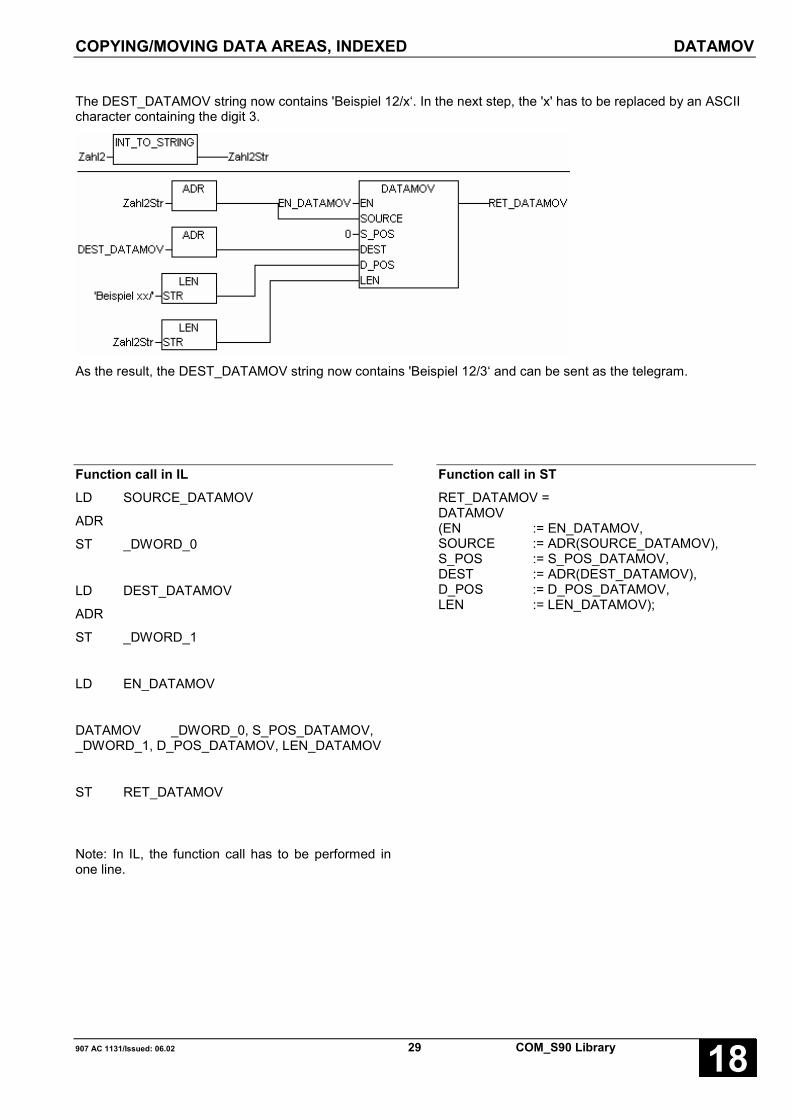
COPYING/MOVING DATA AREAS, INDEXED DATAMOV
907 AC 1131/Issued: 06.02 29 COM_S90 Library 18
The DEST_DATAMOV string now contains 'Beispiel 12/x‘. In the next step, the 'x' has to be replaced by an ASCIIcharacter containing the digit 3.
As the result, the DEST_DATAMOV string now contains 'Beispiel 12/3‘ and can be sent as the telegram.
Function call in ILLD SOURCE_DATAMOV
ADR
ST _DWORD_0
LD DEST_DATAMOV
ADR
ST _DWORD_1
LD EN_DATAMOV
DATAMOV _DWORD_0, S_POS_DATAMOV,_DWORD_1, D_POS_DATAMOV, LEN_DATAMOV
ST RET_DATAMOV
Note: In IL, the function call has to be performed inone line.
Function call in STRET_DATAMOV =DATAMOV(EN := EN_DATAMOV,SOURCE := ADR(SOURCE_DATAMOV),S_POS := S_POS_DATAMOV,DEST := ADR(DEST_DATAMOV),D_POS := D_POS_DATAMOV,LEN := LEN_DATAMOV);
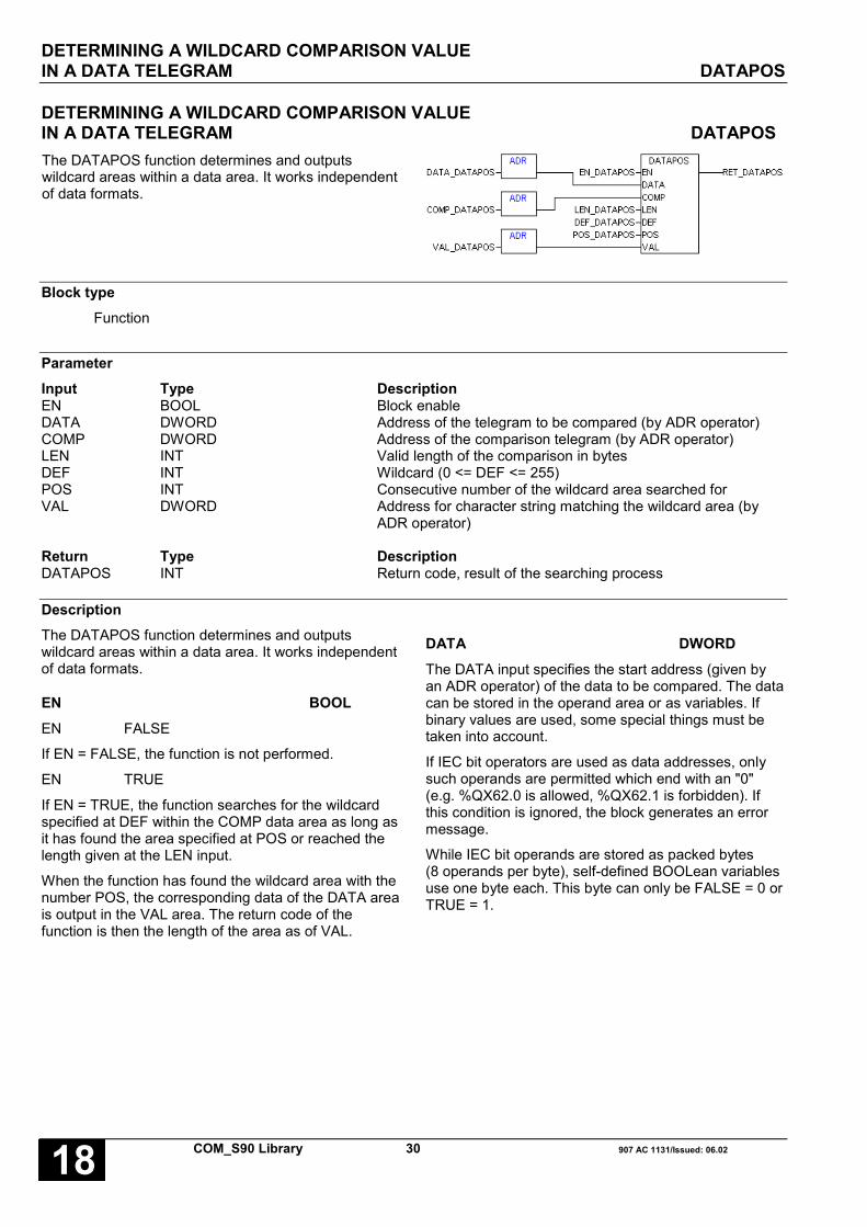
DETERMINING A WILDCARD COMPARISON VALUEIN A DATA TELEGRAM DATAPOS
COM_S90 Library 30 907 AC 1131/Issued: 06.0218
DETERMINING A WILDCARD COMPARISON VALUEIN A DATA TELEGRAM DATAPOSThe DATAPOS function determines and outputswildcard areas within a data area. It works independentof data formats.
Block typeFunction
ParameterInput Type DescriptionEN BOOL Block enableDATA DWORD Address of the telegram to be compared (by ADR operator)COMP DWORD Address of the comparison telegram (by ADR operator)LEN INT Valid length of the comparison in bytesDEF INT Wildcard (0 <= DEF <= 255)POS INT Consecutive number of the wildcard area searched forVAL DWORD Address for character string matching the wildcard area (by
ADR operator)
Return Type DescriptionDATAPOS INT Return code, result of the searching process
DescriptionThe DATAPOS function determines and outputswildcard areas within a data area. It works independentof data formats.
EN BOOLEN FALSE
If EN = FALSE, the function is not performed.
EN TRUE
If EN = TRUE, the function searches for the wildcardspecified at DEF within the COMP data area as long asit has found the area specified at POS or reached thelength given at the LEN input.
When the function has found the wildcard area with thenumber POS, the corresponding data of the DATA areais output in the VAL area. The return code of thefunction is then the length of the area as of VAL.
DATA DWORDThe DATA input specifies the start address (given byan ADR operator) of the data to be compared. The datacan be stored in the operand area or as variables. Ifbinary values are used, some special things must betaken into account.
If IEC bit operators are used as data addresses, onlysuch operands are permitted which end with an "0"(e.g. %QX62.0 is allowed, %QX62.1 is forbidden). Ifthis condition is ignored, the block generates an errormessage.
While IEC bit operands are stored as packed bytes(8 operands per byte), self-defined BOOLean variablesuse one byte each. This byte can only be FALSE = 0 orTRUE = 1.

DETERMINING A WILDCARD COMPARISON VALUEIN A DATA TELEGRAM DATAPOS
907 AC 1131/Issued: 06.02 31 COM_S90 Library 18
COMP DWORDThe COMP input specifies the start address (given byan ADR operator) of the comparison data. The datacan be stored in the operand area or as variables. Ifbinary values are used, some special things must betaken into account.
If IEC bit operators are used as data addresses, onlysuch operands are permitted which end with an "0"(e.g. %QX62.0 is allowed, %QX62.1 is forbidden). Ifthis condition is ignored, the block generates an errormessage.
While IEC bit operands are stored as packed bytes(8 operands per byte), self-defined BOOLean variablesuse one byte each. This byte can only be FALSE = 0 orTRUE = 1.
LEN INTAt the LEN input, the maximum number of bytes has tobe specified which are to be considered whensearching for wildcards DEF within the COMP area.
DEF INTAt the DEF input, the value of the wildcard character isspecified, that is searched for in COMP. For DEF, thevalues 0 <= DEF <= 255 are valid.
POS INTAt the POS input, the consecutive number of thewildcard area in COMP is specified that is searched for.POS must not be confused with the offset within theCOMP area. Each unbroken wildcard area in COMP isevaluated as one position POS.
VAL DWORDThe VAL input specifies the start address of the dataarea where the data have to be stored in DATAcorresponding to the wildcard area in COMP.
The data can be stored in the operand area or asvariables. If binary values are used, some specialthings must be taken into account.
If IEC bit operators are used as data addresses, onlysuch operands are permitted which end with an "0"(e.g. %QX62.0 is allowed, %QX62.1 is forbidden). Ifthis condition is ignored, the block generates an errormessage.
While IEC bit operands are stored as packed bytes(8 operands per byte), self-defined BOOLean variablesuse one byte each. This byte can only be FALSE = 0 orTRUE = 1.
Note: The VAL data area must bedimensioned big enough. It must haveat least the size of the largest possiblewildcard area in COMP.
DATAPOS INTThe return code of the DATAPOS function indicates the valid length of the VAL area (return code > 0) or that anerror occurred (return code < 0).
Parameter / Status ResultEN = FALSE DATAPOS = 0 DATA_NO_ACTION
LEN <= 0 DATAPOS = -1 DATA_INVALID_LENGTH
POS <= 0 DATAPOS = -2 DATA_INVALID_POSITION
Address DATA, COMP or VAL invalid DATAPOS = -3 DATA_INVALID_ADDRESS
Wildcard area number (POS) not found DATAPOS = -4 DATA_AREA_NOT_FOUND
DEF invalid DATAPOS = -5 DATA_INVALID_WILDCARD
No other errors DATAPOS > 0, length of the valid area as of VALin bytes

DETERMINING A WILDCARD COMPARISON VALUEIN A DATA TELEGRAM DATAPOS
COM_S90 Library 32 907 AC 1131/Issued: 06.0218
ExampleFrom a received telegram which has the pattern
'Beispiel xx/x‘
the digit values have to be determined which are contained in the areas marked with 'x'. The received telegram isstored in the DATA_DATAPOS string. As the wildcard, the § character (ASCII 15 hex. / 21 dec.) is defined.
For better understanding, the receiving telegram is fixed in the following example program. Therefore, the variablesare defined at first.
EN_DATAPOS: BOOL;
DATA_DATAPOS: STRING(13):='Beispiel 12/3';
COMP_DATAPOS: STRING(13):='Beispiel $15$15/$15‘;
RET_DATAPOS: INT;
Zahl1Str: STRING(2);
Zahl2Str: STRING(1);
Zahl1: INT;
Zahl2: INT;
The resulting program:

DETERMINING A WILDCARD COMPARISON VALUEIN A DATA TELEGRAM DATAPOS
907 AC 1131/Issued: 06.02 33 COM_S90 Library 18
The following figure shows the way of working of the DATAPOS function.
DATA_DATAPOS
COMP_DATAPOS
§
DEF
LEN = LEN(DATA_DATAPOS) = 13
DATAPOS = LEN(Zahl1Str) = 2
B e i s p i e l 1 2 / 3 STRING
66 101 105 115 112 105 101 108 32 49 50 47 51 ASCII dec
42 65 69 73 70 69 65 6C 20 31 32 2F 33 ASCII hex
B e i s p i e l § § / § STRING
66 101 105 115 112 105 101 108 32 21 21 47 21 ASCII dec
42 65 69 73 70 69 65 6C 20 15 15 2F 15 ASCII hex
STRING
ASCII dec
ASCII hex
21
15
POS = 1
Zahl1Str
1 2 STRING
49 50 ASCII dec
31 32 ASCII hex
3 STRING
51 ASCII dec
33 ASCII hex
Zahl1 = STRING_TO_INT(Zahl1Str) = STRING_TO_INT('12') = 12
POS = 2
DATAPOS = LEN(Zahl2Str) = 1
Zahl2Str
Zahl2 = STRING_TO_INT(Zahl2Str) = STRING_TO_INT('3') = 3
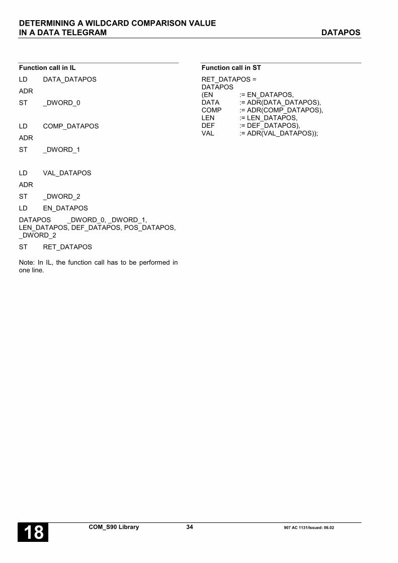
DETERMINING A WILDCARD COMPARISON VALUEIN A DATA TELEGRAM DATAPOS
COM_S90 Library 34 907 AC 1131/Issued: 06.0218
Function call in ILLD DATA_DATAPOS
ADR
ST _DWORD_0
LD COMP_DATAPOS
ADR
ST _DWORD_1
LD VAL_DATAPOS
ADR
ST _DWORD_2
LD EN_DATAPOS
DATAPOS _DWORD_0, _DWORD_1,LEN_DATAPOS, DEF_DATAPOS, POS_DATAPOS,_DWORD_2
ST RET_DATAPOS
Note: In IL, the function call has to be performed inone line.
Function call in STRET_DATAPOS =DATAPOS(EN := EN_DATAPOS,DATA := ADR(DATA_DATAPOS),COMP := ADR(COMP_DATAPOS),LEN := LEN_DATAPOS,DEF := DEF_DATAPOS),VAL := ADR(VAL_DATAPOS));

INITIALIZATION AND CONFIGURATION OF THE MODBUS INTERFACES MODINIT
907 AC 1131/Issued: 06.02 35 COM_S90 Library 18
INITIALIZATION AND CONFIGURATION OF THE MODBUS INTERFACES MODINITWith every FALSE → TRUE edge at input EN, theMODINIT block reads the values at the inputs andinitializes the interface (COM1, COM2, COM3, COM4)specified at input COM.The MODBUS interface is active, until EN is set toTRUE. With a TRUE → FALSE edge at EN, theinterface is enabled for other functions.
Block typeFunction block with historical values
ParametersInstance MODINIT Instance nameEN BOOL Enabling of the block processingCOM INT Interface identifier (COM1, COM2, COM3 or COM4)BAUD INT Data transfer rate (300...19200 baud)PTY INT Parity (no parity bit, odd or even parity)STOP INT Number of stop bits (1, 1½ or 2 stop bits)PTSCTRL BOOL RTS controller (on/off)TLS INT Carrier lead time (0...500 ms)CDLY INT Carrier delay time (0...100 ms)CHTO INT Character timeout (0...500 ms)MAST_SLV INT MODBUS identifier (100 = master, 101...355 = slave
(bus address + 100))RDY BOOL Ready messageERR BOOL Error messageERNO INT Error identifierREC BOOL Telegram receiving messageSND BOOL Telegram sending messageFCT INT Function code of the sent / received telegram
Description
With every FALSE → TRUE edge at input EN, theMODINIT block reads the values at the inputs andinitializes the MODBUS interface of the controller(COM1, COM2) or of the 07 KP 93 (COM3, COM4)specified at input COM.
The MODBUS interface is active, until EN is set toTRUE. With a TRUE → FALSE edge at EN, theinterface is enabled for other functions.
The inputs can neither be duplicated nornegated/inverted.
Serial interfacesThe value processing at the inputs depends on theinterface selected (PLC or 07 KP 93).
Usage of modems
The block MODINIT supports the special features ofmodems, interface converters and repeaters. If they areused at the MODBUS interfaces, the compressionmechanism possibly supported by these devices mustbe deactivated. For detailed information, please refer tothe manual of the respective device.
Some repeaters, modems or interface convertersrequire a control signal to set the transfer direction.
For the interfaces COM1 and COM 2, the directioncontrol can be activated or deactivated via inputRTSCTRL.
Various devices additionally require a lead time tostabilize their carrier signal. These devices are notready to transfer data in sending direction until this timehas elapsed.

INITIALIZATION AND CONFIGURATION OF THE MODBUS INTERFACES MODINIT
COM_S90 Library 36 907 AC 1131/Issued: 06.0218
For the interfaces COM1 and COM 2, the carrier leadtime can be specified via input TLS.
The 07 KP 93 interfaces COM3 and COM4 use nocarrier lead time.
Additionally it is necessary for some devices tomaintain the carrier signal in sending direction for sometime after the data transfer. Only if this time haselapsed, the complete transfer of a telegram is ensuredand the devices are ready for data transfer in oppositedirection.
For the interfaces COM1 and COM 2, the carrier leadtime can be specified via input TLS.
The 07 KP 93 interfaces COM3 and COM4 use nocarrier delay time.
For using modems, a telegram can be possibly split upinto several data blocks during the transfer. Thecharacter timeout defines the time which may passbetween the receiving of two telegram data blockswithout occurring an error message.
For the interfaces COM1 and COM 2, the charactertimeout can be specified via input CHTO.
The 07 KP 93 interfaces COM3 and COM4 use nocharacter timeout.
Note: The carrier lead time and the carrier delay timemust be coordinated at all devices at the bus.
EN BOOL
EN FALSE → TRUE:
If a FALSE → TRUE edge is applied to input EN, allfurther inputs are read in.
If the values at the inputs are valid, the interface whichnumber is specified at input COM is initialized andready for operation afterwards.
If there is at least one input invalid, the error isdisplayed at the outputs ERR and ERNO and thecurrent interface setting is not changed.
EN TRUE:
The MODBUS interface is active, provided no errorsoccurred during the initialization (outputs ERR andERNO). The telegram communication is displayed atthe outputs REC, SND and FCT.
EN TRUE → FALSE:
The MODBUS interface is deactivated and enabled forother applications (only COM1 and COM2). All outputsare set to zero (FALSE).
EN FALSE
The block is not processed. The interface is not usedas MODBUS interface.
COM INTAt input COM the MODBUS interface number isspecified.
COM = 1: COM1 (SPS)COM = 2: COM2 (SPS)COM = 3: COM3 (07 KP 93)COM = 4: COM4 (07 KP 93)
BAUD INTAt input BAUD the value for the data transfer rate isspecified.
The following settings are possible:
COM1 / COM2:
300, 1200, 2400, 4800, 9600, 14400, 19200
COM3 / COM4:
1200, 2400, 4800, 9600, 19200

INITIALIZATION AND CONFIGURATION OF THE MODBUS INTERFACES MODINIT
907 AC 1131/Issued: 06.02 37 COM_S90 Library 18
PTY INTAt input PTY is specified, with which parity a characteris transferred.
Input PTY is only processed, if COM1 or COM2 isdefined as MODBUS interface.
The 07 KP 93 interfaces COM3 and COM4 arepermanently set to no parity bit.
PTY = 0: no parity bit
PTY = 1: odd parity
The number of "1" values within acharacter is increased until an oddnumber is reached.
PTY = 2: even parity
The number of "1" values within acharacter is increased until an evennumber is reached.
STOP INTThe number of stop bits for each character is specifiedat input STOP.
Input STOP is only processed, if COM1 or COM2 isdefined as MODBUS interface.
The 07 KP 93 interfaces COM3 and COM4 arepermanently set to one stop bit.
STOP = 1: 1 stop bit
STOP = 2: 2 stop bits
RTSCTRL BOOLInput RTSCTRL specifies whether the synchronizationbetween MODBUS interface and connected deviceshould be performed via the control signal RTS (noRTS/CTS handshake).
Input RTSCTRL is only processed, if COM1 or COM2is defined as MODBUS interface.
The 07 KP 93 interfaces COM3 and COM4 arepermanently set to RTS/CTS handshake.
For activated RTS control (RTSCTRL = TRUE), thecontrol signals are generated automatically by theinterface.
TLS INTThe carrier lead time in milliseconds (0...500ms) isspecified at input TLS.
Input TLS is only processed, if COM1 or COM2 isdefined as MODBUS interface and RTSCTRL = TRUE.
The 07 KP 93 interfaces COM3 and COM4 use nocarrier lead time.
Note: Keeping the carrier lead time depends on thecycle time of the task in which the MODINIT block isprocessed. The real time may deviate from thespecification in worst case task cycle – 1ms.
CDLY INTThe carrier delay time in milliseconds (0...100ms) isspecified at input CDLY.
Input CDLY is only processed, if COM1 or COM2 isdefined as MODBUS interface and RTSCTRL = TRUE.
The 07 KP 93 interfaces COM3 and COM4 use nocarrier delay time.
Note: Keeping the carrier delay time depends on thecycle time of the task in which the MODINIT block isprocessed. The real time may deviate from thespecification in worst case task cycle – 1ms.
CHTO INTThe character timeout in milliseconds (1...500ms) isspecified at input CHTO.
Input CHTO is only processed, if COM1 or COM2 isdefined as MODBUS interface.
The 07 KP 93 interfaces COM3 and COM4 use nocharacter timeout.
Note: Keeping the character timeout depends on thecycle time of the task in which the MODINIT block isprocessed. The real time may deviate from thespecification in worst case, task cycle – 1ms.
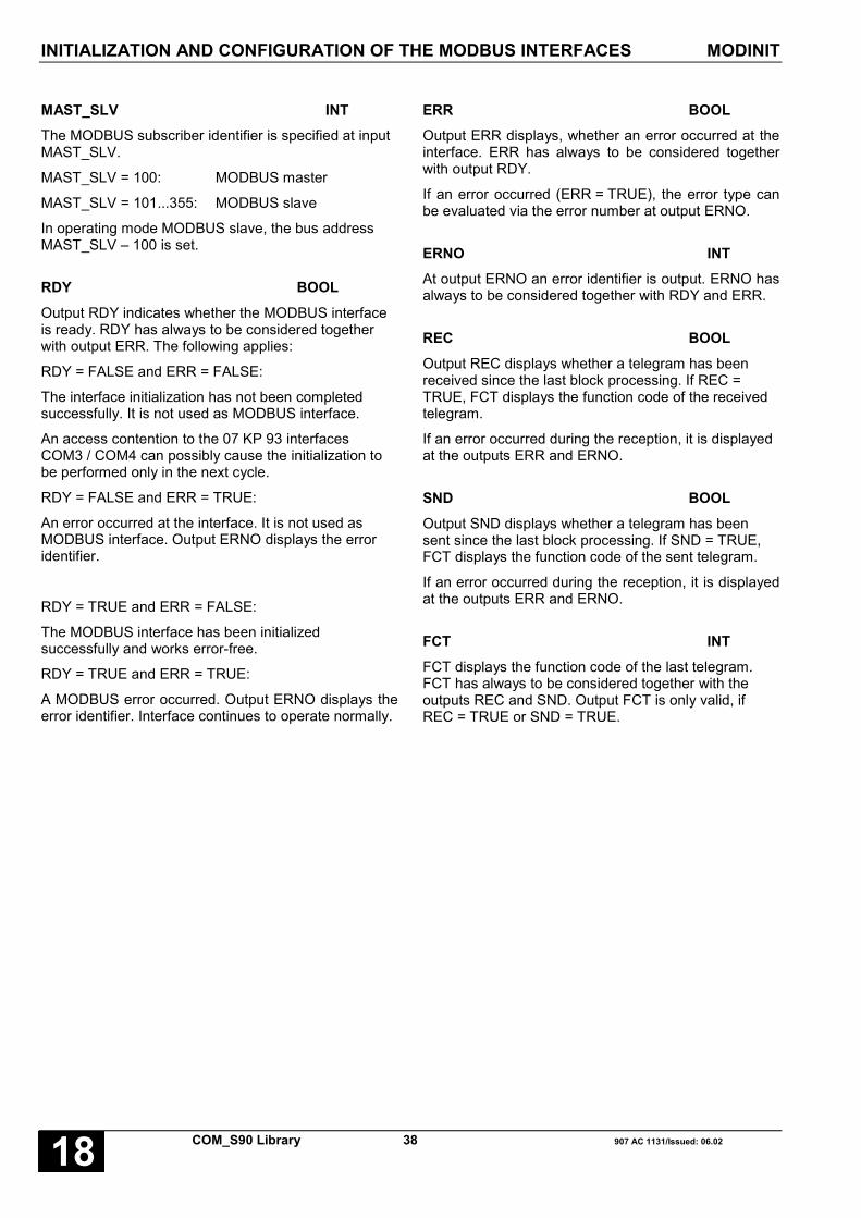
INITIALIZATION AND CONFIGURATION OF THE MODBUS INTERFACES MODINIT
COM_S90 Library 38 907 AC 1131/Issued: 06.0218
MAST_SLV INTThe MODBUS subscriber identifier is specified at inputMAST_SLV.
MAST_SLV = 100: MODBUS master
MAST_SLV = 101...355: MODBUS slave
In operating mode MODBUS slave, the bus addressMAST_SLV – 100 is set.
RDY BOOLOutput RDY indicates whether the MODBUS interfaceis ready. RDY has always to be considered togetherwith output ERR. The following applies:
RDY = FALSE and ERR = FALSE:
The interface initialization has not been completedsuccessfully. It is not used as MODBUS interface.
An access contention to the 07 KP 93 interfacesCOM3 / COM4 can possibly cause the initialization tobe performed only in the next cycle.
RDY = FALSE and ERR = TRUE:
An error occurred at the interface. It is not used asMODBUS interface. Output ERNO displays the erroridentifier.
RDY = TRUE and ERR = FALSE:
The MODBUS interface has been initializedsuccessfully and works error-free.
RDY = TRUE and ERR = TRUE:
A MODBUS error occurred. Output ERNO displays theerror identifier. Interface continues to operate normally.
ERR BOOLOutput ERR displays, whether an error occurred at theinterface. ERR has always to be considered togetherwith output RDY.
If an error occurred (ERR = TRUE), the error type canbe evaluated via the error number at output ERNO.
ERNO INTAt output ERNO an error identifier is output. ERNO hasalways to be considered together with RDY and ERR.
REC BOOLOutput REC displays whether a telegram has beenreceived since the last block processing. If REC =TRUE, FCT displays the function code of the receivedtelegram.
If an error occurred during the reception, it is displayedat the outputs ERR and ERNO.
SND BOOLOutput SND displays whether a telegram has beensent since the last block processing. If SND = TRUE,FCT displays the function code of the sent telegram.
If an error occurred during the reception, it is displayedat the outputs ERR and ERNO.
FCT INTFCT displays the function code of the last telegram.FCT has always to be considered together with theoutputs REC and SND. Output FCT is only valid, ifREC = TRUE or SND = TRUE.

INITIALIZATION AND CONFIGURATION OF THE MODBUS INTERFACES MODINIT
907 AC 1131/Issued: 06.02 39 COM_S90 Library 18
Function call in ILCAL MODINIT_COM1
(EN := MOD1_EN,COM := MOD1_COM,BAUD := MOD1_BAUD,PTY := MOD1_PTY,STOP := MOD1_STOP,RTSCTRL := MOD1_RTSCTRL,TLS := MOD1_TLS,CDLY := MOD1_CDLY,CHTO := MOD1_CHTO,MAST_SLV := MOD1_MAST_SLV)
LD MODINIT_COM1.RDYST MOD1_RDYLD MODINIT_COM1.ERRST MOD1_ERRLD MODINIT_COM1.ERNOST MOD1_ERNOLD MODINIT_COM1.RECST MOD1_RECLD MODINIT_COM1.SNDST MOD1_SNDLD MODINIT_COM1.FCTST MOD1_FCT
Note: In IL, the function call has to be performed inone line.
Function call in STMODINIT_COM1
(EN := MOD1_EN,COM := MOD1_COM,BAUD := MOD1_BAUD,PTY := MOD1_PTY,STOP := MOD1_STOP,RTSCTRL := MOD1_RTSCTRL,TLS := MOD1_TLS,CDLY := MOD1_CDLY,CHTO := MOD1_CHTO,MAST_SLV := MOD1_MAST_SLV);
MOD1_RDY := MODINIT_COM1.RDY;MOD1_ERR := MODINIT_COM1.ERR;MOD1_ERNO:= MODINIT_COM1.ERNO;MOD1_REC := MODINIT_COM1.REC;MOD1_SNE := MODINIT_COM1.SND;MOD1_FCT := MODINIT_COM1.FCT;

MODBUS-MASTER MODMAST
COM_S90 Library 40 907 AC 1131/Issued: 06.0218
OPERATION MODE MODBUS MASTER MODMASTThe block MODMAST realizes the MODBUS masterfunction for the MODBUS interface (COM1, COM2,COM3, COM4) specified at input COM.
For each interface, a separate MODMAST block mustbe used.
Before MODMAST can be used for an interface, thismust be configured as a MODBUS master interface viathe block MODINIT.
With each FALSE → TRUE edge at input EN, thefunction block MODMAST reads the values at theinputs, generates a telegram according to the inputsand sends this telegram to the slave.
Block typeFunction block with historical values
ParameterInstance MODMAST Instance nameEN BOOL Enabling of the block processingCOM INT Interface identifier (COM1, COM2, COM3 or COM4)SLAVE INT Slave address (1...255)FCT INT Function codeTIMEOUT INT Telegram timeout in millisecondsADDR INT Operand/register address in the slaveNB INT Number of dataDATA DWORD First operand address of an operand area in the master, from which data
are sent to the slave or data read by the slave should be stored.RDY BOOL Ready messageERR BOOL Error messageERNO INT Error identifier
DescriptionThe block MODMAST realizes the MODBUS masterfunction for the MODBUS interface of the controller(COM1, COM2) or the 07 KP 93 (COM3, COM4)specified at input COM.
For each interface, a separate MODMAST blockmust be used.
Before MODMAST can be used for an interface, thismust be configured as a MODBUS master interfacevia the block MODINIT.
With each FALSE → TRUE edge at input EN, thefunction block MODMAST reads the values at theinputs, generates a telegram according to the inputsand sends this telegram to the slave.
Using several MODMAST for one interface, it has tobe ensured that always only one MODMAST isenabled.
The inputs can neither be duplicated nornegated/inverted.

OPERATION MODE MODBUS MASTER MODMAST
907 AC 1131/Issued: 06.02 41 COM_S90 Library 18
EN BOOL
If a FALSE → TRUE edge is applied to input EN, allfurther inputs are read in.
If the input values are valid, a request telegram issent to a slave.
If at least one input is invalid, no telegram isgenerated and the error is displayed at the outputsERR and ERNO instead.
COM INTAt input COM the MODBUS interface number isspecified.
COM = 1: COM1 (SPS)COM = 2: COM2 (SPS)COM = 3: COM3 (07 KP 93)COM = 4: COM4 (07 KP 93)
SLAVE INTAt input SLAVE the address of the slave to which atelegram should be sent is specified. Valid values are1...255.
FCT INTThe function code of the request telegram is specifiedat input FCT.
01 or 02 read n bits03 or 04 read n words05 write one bit06 write one word07 read M01,00...M01,0715 write n bits16 write n words
Note: Function 07 is only available for COM1 /COM2.
TIMEOUT INTThe telegram timeout in milliseconds (ms) is specifiedat input TIMEOUT.
If no response is received within the time intervalspecified in TIMEOUT, the procedure is aborted andan error identifier is output.
Note: Keeping the timeout depends on the cycle timeof the task in which the MODMAST block isprocessed. The real time may deviate from thespecification in worst case task cycle – 1ms.
ADDR INTThe operand/register address in the slave from whichdata should be read or written is specified at inputADDR.
The access to operands of AC31 devices inMODBUD slave mode is defined via the MODBUScross-reference list. Only operands can be usedwhich are listed in the cross-reference list.
NB INTThe number of data to be written or read is specifiedat input NB.
The unit of NB depends on the selected function. Forbit accesses the number of bits, for word and doubleword accesses the number of words is specified atNB.
The following restrictions apply to the length:
FCT NBmax01 or 02 96 bit03 or 04 96 words / 48 double words05 1 bit06 1 word07 8 bit15 192 bit16 96 words / 48 double words
DATA DWORDThe first operand address of an operand area in themaster, from which data are written to the slave or inwhich the data read by the slave should be stored isspecified at input DATA. Only operands can be usedwhich are listed in the cross-reference list.
The ADR operator provides the address of anoperand.

OPERATION MODE MODBUS MASTER MODMAST
COM_S90 Library 42 907 AC 1131/Issued: 06.0218
RDY BOOLOutput RDY indicates whether the MODBUS isready. Only with RDY = TRUE, the master is ready tosend a new telegram.
RDY has always to be considered together withoutput ERR. The following applies:
RDY = FALSE and ERR = FALSE:
The processing of the last request has not beencompleted.
RDY = FALSE and ERR = TRUE:
An error occurred at the interface. Output ERNOdisplays the error identifier.
RDY = TRUE and ERR = FALSE:
The processing of the last request has beencompleted successfully.
RDY = TRUE and ERR = TRUE:
At least one input is invalid or a MODBUS erroroccurred. Output ERNO displays the error identifier.Interface continues to operate normally.
ERR BOOLOutput ERR displays whether an error occurred. ERRhas always to be considered together with outputRDY.
If an error occurred (ERR = TRUE), the error typecan be evaluated via the error number at outputERNO.
ERNO INTAt output ERNO an error identifier is output. ERNOhas always to be considered together with RDY andERR.
Function call in ILLD OperandADRST MODM1_DATA
CAL MODMAST_COM1(EN := MODM1_EN,COM := MODM1_COM,SLAVE := MODM1_SLAVE,FCT := MODM1_FCT,TIMEOUT := MODM1_TIMEOUT,ADDR := MODM1_ADDR,NB := MODM1_NB,DATA := MODM1_DATA)
LD MODMAST_COM1.RDY
ST MODM1_RDY
LD MODMAST_COM1.ERR
ST MODM1_ERR
LD MODMAST_COM1.ERNO
ST MODM1_ERNO
Note: In IL, the function call has to be performed inone line.
Function call in STMODMAST_COM1
(EN := MODM1_EN,COM := MODM1_COM,SLAVE := MODM1_SLAVE,FCT := MODM1_FCT,TIMEOUT := MODM1_TIMEOUT,ADDR := MODM1_ADDR,NB := MODM1_NB,DATA := ADR(Operand));
MODM1_RDY := MODMAST_COM1.RDY;MODM1_ERR := MODMAST_COM1.ERR;MODM1_ERNO:= MODMAST_COM1.ERNO;
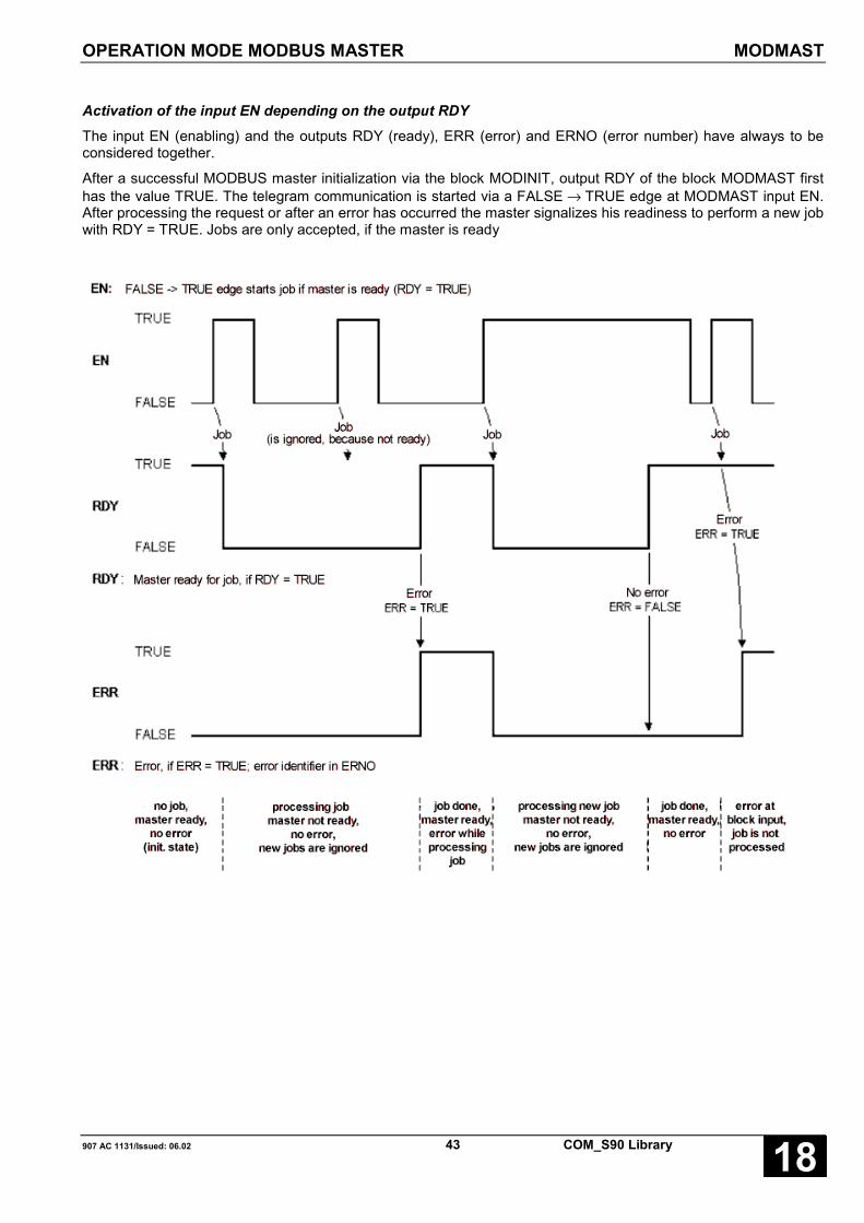
OPERATION MODE MODBUS MASTER MODMAST
907 AC 1131/Issued: 06.02 43 COM_S90 Library 18
Activation of the input EN depending on the output RDYThe input EN (enabling) and the outputs RDY (ready), ERR (error) and ERNO (error number) have always to beconsidered together.
After a successful MODBUS master initialization via the block MODINIT, output RDY of the block MODMAST firsthas the value TRUE. The telegram communication is started via a FALSE → TRUE edge at MODMAST input EN.After processing the request or after an error has occurred the master signalizes his readiness to perform a new jobwith RDY = TRUE. Jobs are only accepted, if the master is ready
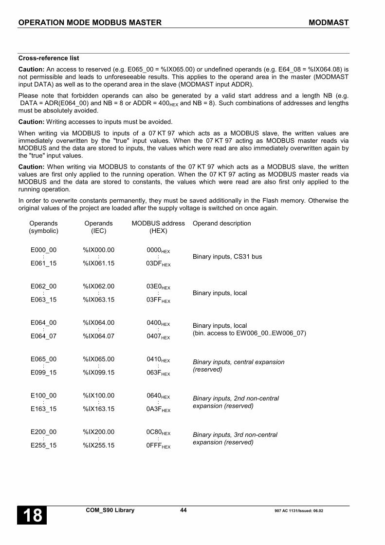
OPERATION MODE MODBUS MASTER MODMAST
COM_S90 Library 44 907 AC 1131/Issued: 06.0218
Cross-reference listCaution: An access to reserved (e.g. E065_00 = %IX065.00) or undefined operands (e.g. E64_08 = %IX064.08) isnot permissible and leads to unforeseeable results. This applies to the operand area in the master (MODMASTinput DATA) as well as to the operand area in the slave (MODMAST input ADDR).
Please note that forbidden operands can also be generated by a valid start address and a length NB (e.g. DATA = ADR(E064_00) and NB = 8 or ADDR = 400HEX and NB = 8). Such combinations of addresses and lengthsmust be absolutely avoided.
Caution: Writing accesses to inputs must be avoided.
When writing via MODBUS to inputs of a 07 KT 97 which acts as a MODBUS slave, the written values areimmediately overwritten by the "true" input values. When the 07 KT 97 acting as MODBUS master reads viaMODBUS and the data are stored to inputs, the values which were read are also immediately overwritten again bythe "true" input values.
Caution: When writing via MODBUS to constants of the 07 KT 97 which acts as a MODBUS slave, the writtenvalues are first only applied to the running operation. When the 07 KT 97 acting as MODBUS master reads viaMODBUS and the data are stored to constants, the values which were read are also first only applied to therunning operation.
In order to overwrite constants permanently, they must be saved additionally in the Flash memory. Otherwise theoriginal values of the project are loaded after the supply voltage is switched on once again.
Operands(symbolic)
Operands(IEC)
MODBUS address(HEX)
Operand description
E000_00:
E061_15
%IX000.00:
%IX061.15
0000HEX:
03DFHEX
Binary inputs, CS31 bus
E062_00:
E063_15
%IX062.00:
%IX063.15
03E0HEX:
03FFHEX
Binary inputs, local
E064_00:
E064_07
%IX064.00:
%IX064.07
0400HEX:
0407HEX
Binary inputs, local(bin. access to EW006_00..EW006_07)
E065_00:
E099_15
%IX065.00:
%IX099.15
0410HEX:
063FHEX
Binary inputs, central expansion(reserved)
E100_00:
E163_15
%IX100.00:
%IX163.15
0640HEX:
0A3FHEX
Binary inputs, 2nd non-centralexpansion (reserved)
E200_00:
E255_15
%IX200.00:
%IX255.15
0C80HEX:
0FFFHEX
Binary inputs, 3rd non-centralexpansion (reserved)

OPERATION MODE MODBUS MASTER MODMAST
907 AC 1131/Issued: 06.02 45 COM_S90 Library 18
E256_00:
E263_15
%IX256.00:
%IX263.15No directaccess
Binary inputs, 3rd non-centralexpansion (reserved)
%IX1.1.0000.0:
%IX1.1792.15No directaccess Binary inputs, PROFIBUS line 1
%IX2.1.0000.0:
%IX2.1792.15No direct
acess Binary inputs, PROFIBUS line 2
A000_00:
A061_15
%QX000.00:
%QX061.15
1000HEX:
13DFHEX
Binary outputs, CS31 bus
A062_00:
A063_15
%QX062.00:
%QX063.15
13E0HEX:
13FFHEX
Binary outputs, local
A064_00:
A099_15
%QX064.00:
%QX099.15
1400HEX:
163FHEX
Binary outputs, central expansion(reserved
A100_00:
A163_15
%QX100.00:
%QX163.15
1640HEX:
1A3FHEX
Binary outputs, 2nd non-centralexpansion (reserved
A200_00:
A255_15
%QX200.00:
%QX255.15
1C80HEX:
1FFFHEX
Binary outputs, 3rd non-centralexpansion (reserved)
A256_00:
A263_15
%QX256.00:
%QX263.15No directaccess
Binary outputs, 3rd non-centralexpansion (reserved)
%QX1.1.0000.0:
%QX1.1792.15No directaccess Binary outputs, PROFIBUS line 1
%QX2.1.0000.0:
%QX2.1792.15No directaccess Binary outputs, PROFIBUS line 2
M000_00:
M254_15
%MX0000.00:
%MX0254.15
2000HEX:
2FEFHEX
Binary flags

OPERATION MODE MODBUS MASTER MODMAST
COM_S90 Library 46 907 AC 1131/Issued: 06.0218
M255_00:
M255_15
%MX0255.00:
%MX0255.15
2FF0HEX:
2FFFHEX
Binary flags (system)
M256_00:
M279_15
%MX0256.00:
%MX0279.15No directaccess
Binary flags (system)(reserved)
M280_00:
M511_15
%MX0256.00:
%MX0511.15No directaccess Binary flags (system)
S000_00:
S255_15
%MX5000.00:
%MX5255.15
3000HEX:
3FFFHEX
Steps
EW000_00:
EW005_15
%IW1000.00:
%IW1005.15
0000HEX:
005FHEX
Analog inputs, CS31 bus
EW006_00:
EW006_07
%IW1006.00:
%IW1006.07
0060HEX:
0067HEX
Analog inputs, local
EW007_00:
EW007_14
%IW1007.00:
%IW1007.14
0070HEX:
007EHEX
Analog inputs(reserved)
EW007_15 %IW1007.15 007FHEX Analog input, status word CS31-Bus
EW008_00:
EW015_15
%IW1008.00:
%IW1015.15
0080HEX:
00FFHEX
Analog inputs, CS31 bus
EW016_00:
EW034_15
%IW1016.00:
%IW1034.15
0100HEX:
022FHEX
Analog inputs, central expansion(reserved)
EW100_00:
EW107_15
%IW1100.00:
%IW1107.15
0640HEX:
06BFHEX
Analog inputs, 1st non-centralexpansion (reserved)
EW200_00:
EW207_15
%IW1200.00:
%IW1207.15
0C80HEX:
0CFFHEX
Analog inputs, 2nd non-centralexpansion (reserved)

OPERATION MODE MODBUS MASTER MODMAST
907 AC 1131/Issued: 06.02 47 COM_S90 Library 18
%IW1.0000:
%IW1.1792No directaccess Analog inputs, PROFIBUS line 1
%IW2.0000:
%IW2.1792No directaccess Analog inputs, PROFIBUS line 2
AW000_00:
AW005_15
%QW1000.00:
%QW1005.15
1000HEX:
105FHEX
Analog outputs, CS31 bus
AW006_00:
AW006_03
%QW1006.00:
%QW1006.03
1060HEX:
1063HEX
Analog outputs, local
AW007_00:
AW007_15
%QW1007.00:
%QW1007.15
1070HEX:
107FHEX
Analog outputs(reserved))
AW008_00:
AW015_15
%QW1008.00:
%QW1015.15
1080HEX:
10FFHEX
Analog outputs, CS31 bus
AW016_00:
AW034_15
%QW1016.00:
%QW1034.15
1100HEX:
122FHEX
Analog outputs, central expansion(reserved)
AW100_00:
AW107_15
%QW1100.00:
%QW1107.15
1640HEX:
16BFHEX
Analog outputs, 1st non-centralexpansion (reserved)
AW200_00:
AW207_15
%QW1200.00:
%QW1207.15
1C80HEX:
1CFFHEX
Analog outputs, 2nd non-centralexpansion (reserved)
%QW1.0000:
%QW1.1792No directaccess Analog outputs, PROFIBUS line 1
%QW2.0000:
%QW2.1792No directaccess Analog outputs, PROFIBUS line 2
MW000_00:
MW253_15
%MW1000.00:
%MW1253.15
2000HEX:
2FDFHEX
Word flags

OPERATION MODE MODBUS MASTER MODMAST
COM_S90 Library 48 907 AC 1131/Issued: 06.0218
MW254_00:
MW255_15
%MW1254.00:
%MW1255.15
2FE0HEX:
2FFFHEX
Word flags (error message)
MW256_00:
MW259_15
%MX1256.00:
%MX1259.15No directaccess
Word flags (system)(reserved)
MW260_00:
MW511_15
%MW1260.00:
%MW1511.15No directaccess Word flags (user area)
KW000_00:
KW000_15
%MW3000.00:
%MW3000.15
3000HEX:
300FHEX
Word constants (system)
KW001_00:
KW079_15
%MW3001.00:
%MW3079.15
3010HEX:
34FFHEX
Word constants
KW080_00:
KW089_15
%MW3080.00:
%MW3089.15
3500HEX:
359FHEX
Word constants (system)
MD000_00:
MD063_15
%MD2000.00:
%MD2063.15
4000HEX:
43FFHEX
Double word flags
KD000_00 %MD4000.00 5000HEX Double word constant (system)
KD000_01:
KD023_15
%MD4000.01:
%MD4023.15
5001HEX:
517FHEX
Double word constants

OPERATION MODE MODBUS MASTER MODMAST
907 AC 1131/Issued: 06.02 49 COM_S90 Library 18
Error numbers at output ERNO of the blocks MODINIT and MODMAST
ERNO Meaning
0 No error
1 Function is not supported
Master:Invalid value at input FCT of block MODMAST for corresponding COMorSlave responds with error telegram because it does not support the requested function
Slave: Master requests function which the controller does not support
2 Invalid operand address
Master:Slave responds with error telegram, invalid value for corresponding COM at input ADDR ofblock MODMAST
Slave:Master attempts to access to an invalid operand address
2 Operand range exceeded
Master:Slave responds with error telegram, combination of input ADDR and input NB of blockMODMAST for corresponding COM exceed operand range limit in slaveorCombination of input DATA and input NB of block MODMAST for corresponding COMexceed operand range limit in master
Slave:Master attempts to access to data which exceed an operand range limit
3 Date is outside the permitted value range
Master:Writing access to slave with invalid value, slave cannot process value
10 Length specifications in the telegram do not match
Master/Slave:Transfer error or error while generating the telegram
11 Type of operand area and function code do not match
Master:Invalid combination of input ADDR and input FCT of block MODMAST for correspondingCOMorInvalid combination of input DATA and input FCT of block MODMAST for correspondingCOM
Slave:Master sends telegram which access type (bit / word) does not match with the operandrange

OPERATION MODE MODBUS MASTER MODMAST
COM_S90 Library 50 907 AC 1131/Issued: 06.0218
12 Data length is greater than the permitted value
Master:Invalid value at input NB of block MODMAST for corresponding COM
Slave:Master request exceeds the max. data length which can be processed
13 Odd number of words during double word access
Master:Input ADDR of block MODMAST for corresponding COM has encoding for double wordoperand range and input NB has odd number of wordsorInput DATA of block MODMAST for corresponding COM has encoding for double wordoperand range and input NB has odd number of words
Slave:
Master attempts to access to double word operand but length specification in telegramcontains odd number of words
15 Initialization error
Master:Block MODMAST for corresponding COM attempts to access to interface although this hasnot been initialized by MODINIT
18 Checksum error
Master/Slave:Telegram contains wrong check sum, transfer error
20 Invalid interface
Master/SlaveInvalid interface at input COM
50 Interface assigned by 907 AC 1131
Master/Slave:Interface at input COM is used as programming interface and cannot be used as MODBUSinterface
51 Baud rate not supported
Master/Slave:Input BAUD has invalid value
52 Parity not supported
Master/Slave:Input PTY has invalid value
53 Number of stop bits not supported
Master/Slave:Input STOP has invalid value
54 Carrier lead not supported
Master/Slave:Input TLS has invalid value
55 Carrier delay not supported
Master/Slave:Input CDLY has invalid value

OPERATION MODE MODBUS MASTER MODMAST
907 AC 1131/Issued: 06.02 51 COM_S90 Library 18
56 Carrier delay longer than carrier lead
Master/Slave:Input CDLY > input TLS
57 Character timeout not supported
Master/Slave:Input CHTO has invalid value
58 Invalid MODBUS subscriber identifier
Master/Slave:Input MAST_SLV has invalid value
59 No bridge at COM
Master/Slave:Interface has no bridge between pin 6 and pin 8, cable not plugged or pulled off
60 Timeout during reception
Master:Master did not receive a complete telegram within the specified time at input TIMEOUT ofblock MODMAST for corresponding COM
Slave:Too long pause during the reception of a master telegram, telegram is interrupted
61 Timeout during sending
Master/Slave:Interface did not send the telegram within the specified time
62 No MODBUS interface
Master/Slave:Interface has been reconfigured by another block; operation as MODBUS interface is onlypossible after new initialization
63 Interface not configured as MODBUS master
Master:MODMAST reads interface which has not been configured before as a MODBUS masterusing MODINIT
65 907 AC 1131 logged on
Master/Slave:907 AC 1131 is logged on at input COM via the interface, interface cannot be used asMODBUS interface until 907 AC 1131 is logged off
66 MODBUS driver not ready
Master:MODMAST reads interface although the processing of the existing request has not yet beencompleted
67 Master/Slave:Parity, overflow or framing error on interface
68 Master/Slave:Character timeout exceeded
69 Master:
Slave address at input SLAVE of block MODMAST is not within the range 1...255
101 COM3 / COM4:No 07 KP 93

OPERATION MODE MODBUS MASTER MODMAST
COM_S90 Library 52 907 AC 1131/Issued: 06.0218
103 COM3 / COM4:Invalid request received
104 COM3 / COM4:Invalid operation mode
105 COM3 / COM 4:Life identifier failed

RECEIVING A DATA SET FROM THECOMMUNICATION MODULE 07 KP 92 SIREC
907 AC 1131/Issued: 06.02 53 COM_S90 Library 18
RECEIVING A DATA SET FROM THECOMMUNICATION MODULE 07 KP 92 SIRECThis block reads data from the DP RAM of thecommunication module. In the communication module,these data can be supplied using the functionplc_send.
Block typeFunction block without historical values
ParametersInstance SIREC Instance nameEN BOOL Enabling of the block processingCOM INT Number of the serial interface; 3 corresponds to COM 3, 4
corresponds to COM 4MAX INT Max. permissible number of data set wordsSMW INT Starting word flag for storing the data setLEN INT Number of read words of the data setNEW BOOL Outputs are validERR INT Error has occurredERNO INT Error number
DescriptionThe block receives a data set from the communicationmodule 07 KP 92 and stores it in the planned word flagarea. The communication module has 2 serialinterfaces (COM3 and COM4). A transmission range isavailable for each serial interface. The block reads thedata set from the assigned area.
Input SMW specifies, where the data set read is stored.Input COM specifies to which communication moduleinterface the data set is assigned.
Note:The start variable must be either an addressablevariable (%MW.., %IW.., %QW..) or an ARRAY. Allother variables are freely defined by the system andtherefore have no definite order.
The enabled input (input EN = TRUE) checks, if a newdata set is available in its transmission range. In thiscase, the data set is transferred to the planned wordflag area and output NEW is set to »TRUE« for a cycle.If no error occurred when reading the data, the outputsERR and ERNO are additionally set to zero. The dataset is stored beginning at the defined start word flagSMW. The number of received words is available atoutput LEN.
If an error occurs during the reading procedure, LEN isset to 0, NEW to TRUE and ERR to 1. The error type isindicated at output ERNO.
The outputs LEN, NEW, ERR and ERNO are set tozero by a zero signal at input EN. If the block is
enabled (input EN = TRUE) and no new data set isavailable in the assigned transmission range, theoutputs NEW, ERR and ERNO are set to zero.
EN BOOLBlock enabling
EN = FALSE → the block is not processed; the outputsLEN, NEW, ERR and ERNO are set tozero.
EN = TRUE → the block is processed.
COM INTThe number of the serial interface of thecommunication module which is assigned to the blockis specified at input COM.
The following applies:
• 3 corresponds to COM 3• 4 corresponds to COM 4
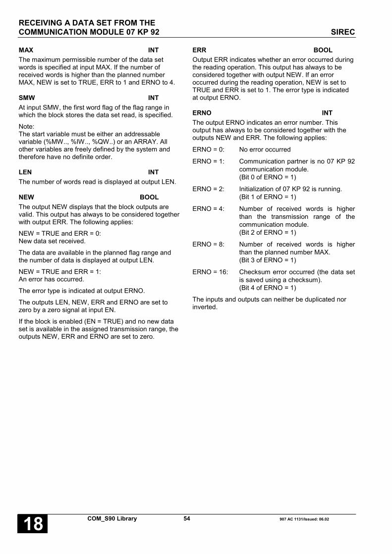
RECEIVING A DATA SET FROM THECOMMUNICATION MODULE 07 KP 92 SIREC
COM_S90 Library 54 907 AC 1131/Issued: 06.0218
MAX INTThe maximum permissible number of the data setwords is specified at input MAX. If the number ofreceived words is higher than the planned numberMAX, NEW is set to TRUE, ERR to 1 and ERNO to 4.
SMW INTAt input SMW, the first word flag of the flag range inwhich the block stores the data set read, is specified.
Note:The start variable must be either an addressablevariable (%MW.., %IW.., %QW..) or an ARRAY. Allother variables are freely defined by the system andtherefore have no definite order.
LEN INTThe number of words read is displayed at output LEN.
NEW BOOLThe output NEW displays that the block outputs arevalid. This output has always to be considered togetherwith output ERR. The following applies:
NEW = TRUE and ERR = 0:New data set received.
The data are available in the planned flag range andthe number of data is displayed at output LEN.
NEW = TRUE and ERR = 1:An error has occurred.
The error type is indicated at output ERNO.
The outputs LEN, NEW, ERR and ERNO are set tozero by a zero signal at input EN.
If the block is enabled (EN = TRUE) and no new dataset is available in the assigned transmission range, theoutputs NEW, ERR and ERNO are set to zero.
ERR BOOLOutput ERR indicates whether an error occurred duringthe reading operation. This output has always to beconsidered together with output NEW. If an erroroccurred during the reading operation, NEW is set toTRUE and ERR is set to 1. The error type is indicatedat output ERNO.
ERNO INTThe output ERNO indicates an error number. Thisoutput has always to be considered together with theoutputs NEW and ERR. The following applies:
ERNO = 0: No error occurred
ERNO = 1: Communication partner is no 07 KP 92communication module.(Bit 0 of ERNO = 1)
ERNO = 2: Initialization of 07 KP 92 is running.(Bit 1 of ERNO = 1)
ERNO = 4: Number of received words is higherthan the transmission range of thecommunication module.(Bit 2 of ERNO = 1)
ERNO = 8: Number of received words is higherthan the planned number MAX.(Bit 3 of ERNO = 1)
ERNO = 16: Checksum error occurred (the data setis saved using a checksum).(Bit 4 of ERNO = 1)
The inputs and outputs can neither be duplicated norinverted.

RECEIVING A DATA SET FROM THECOMMUNICATION MODULE 07 KP 92 SIREC
907 AC 1131/Issued: 06.02 55 COM_S90 Library 18
Function call in ILCAL SIREC1(FREI := SIR_FREI,
COM := SIR_COM,ANZ_MAX := SIR_ANZM,SMW := SIR_SMW)
LD SIREC1.NEWST SIR_NEWLD SIREC1.ERRST SIR_ERRLD SIREC1.ERNOST SIR_ERNOLD SIREC1.LENST SIR_LEN
Note: In IL, the function call has to be performed inone line.
Function call in STSIREC1(FREI := SIR_FREI,COM := SIR_COM,ANZ_MAX := SIR_ANZM,SMW := SIR_SMW);SIR_NEW :=SIREC1.NEW;SIR_ERR :=SIREC1.ERR;SIR_ERNO :=SIREC1.ERNO;SIR_LEN :=SIREC1.LEN;

SENDING A DATA SET TO THECOMMUNICATON MODULE 07 KP 92 SISEND
COM_S90 Library 56 907 AC 1131/Issued: 06.0218
SENDING A DATA SET TO THECOMMUNICATON MODULE 07 KP 92 SISENDThis block writes data to the DP RAM of thecommunication module. From the communicationmodule, these data can be read using the functionplc_rec.
Block typeFunction block with historical values
ParameterInstance SISEND Instance nameEN BOOL Transmission of a data set by a FALSE/TRUE edgeCOM INT Number of the serial interface; 3 corresponds to COM 3, 4 corresponds to
COM 4LEN INT Number of data set words to be sentSMW INT Starting word flag of the word range to be sentRDY BOOL Transmission completedERR BOOL Error has occurredERNO INT Error number
DescriptionThe block sends a data set to the communicationmodule 07 KP 92. The communication module has 2serial interfaces (COM 3 and COM 4). A transmissionrange is available for each interface. The block writesthe data set to the assigned area. The data can befurther processed in the 07 KP 92.
The inputs LEN and SMW define which data are writtento the transmission range. Input COM defines for whichinterface of the communication module these data arespecified. When the transmission of a data set isstarted (FALSE/TRUE edge at input EN), the data atthe inputs LEN and SMW must not be changed until theend of the transmission (RDY = TRUE).
Note:The start variable must be either an addressablevariable (%MW.., %IW.., %QW..) or an ARRAY. Allother variables are freely defined by the system andtherefore have no definite order.
With a FALSE/TRUE edge at input EN the data settransmission is performed once. Until the transmissionhas not been finished (RDY = TRUE), input EN will notbe evaluated again.
After the transmission is completed, all block outputsare updated. The transmission was successful, if RDY= TRUE and ERR = FALSE. For the outputs RDY =TRUE and ERR = TRUE, an error occurred. The errortype is indicated at output ERNO. If the transmissionrange of the communication module is busy, RDYremains FALSE and with the next block call it isattempted again to transmit the data set. This
procedure is repeated until the data set has beentransmitted.
After transmitting the data set, a FALSE signal at inputFREI sets all block outputs to zero (FALSE). A newFALSE/TRUE edge at input FREI starts a newtransmission.
EN BOOLProcessing of the block is controlled via input FREI.
EN FALSE:All outputs are set to the value FALSE (0). This is notvalid during a transmission procedure.
EN FALSE/TRUE-Flanke:Transmission of the data set is started once. Until thetransmission has not been finished (RDY = TRUE),input EN will not be evaluated again.
EN TRUE:The block is not processed, i. e. it no longer changes itsoutputs. This is not valid during a transmissionprocedure.

SENDING A DATA SET TO THECOMMUNICATON MODULE 07 KP 92 SISEND
907 AC 1131/Issued: 06.02 57 COM_S90 Library 18
COM INTThe number of the serial interface of thecommunication module which is assigned to the blockis specified at input COM.
The following applies:
• 3 corresponds to COM 3• 4 corresponds to COM 4
LEN INTThe number of the data set words is specified at inputLEN.
SMW INTThe first word flag of the data set is specified at inputSMW.
Note:The start variable must be either an addressablevariable (%MW.., %IW.., %QW..) or an ARRAY. Allother variables are freely defined by the system andtherefore have no definite order.
RDY BOOLOutput RDY indicates that the data set transmissionhas been completed. This output has always to beconsidered together with output ERR.
The following applies:
RDY = TRUE and ERR = FALSE:The transmission has been completed. The data sethas been transmitted to the 07 KP 92.
RDY = TRUE and ERR = TRUE:An error occurred during the transmission. OutputERNO signalizes the error number.
ERR BOOLOutput ERR indicates whether an error occurred duringthe transmission. This output has always to beconsidered together with output RDY. If an error hasoccurred, the following applies:
RDY = TRUE and ERR = TRUE:Output ERNO signalizes the error number.
ERNO INTThe output ERNO indicates an error number. Thisoutput has always to be considered together with theoutputs RDY and ERR.
The following applies:
ERNO = 0: No error occurred
ERNO = 1: Communication partner is no 07 KP 92communication module.(Bit 0 of ERNO = 1)
ERNO = 2: Initialization of 07 KP 92 is running.(Bit 1 of ERNO = 1)
ERNO = 4: Number of words to be sent is higherthan the transmission range of thecommunication module.(Bit 2 of ERNO = 1)
The inputs and outputs can neither be duplicated norinverted.
Function call in ILCAL SISEND1(FREI := SIS_FREI,
COM := SIS_COM, ANZ := SIS_ANZ,SMW := SIS_SMW)
LD SISEND1.ERRST SIS_ERRLD SISEND1.ERNOST SIS_ERNOLD SISEND1.RDYST SIS_RDY
Note: In IL, the function call has to be performed inone line.
Function call in STSISEND1(FREI := SIS_FREI, COM := SIS_COM,ANZ := SIS_ANZ, SMW := SIS_SMW);SIS_ERR:=SISEND1.ERR;SIS_ERNO:=SISEND1.ERNO;SIS_RDY:=SISEND1.RDY;

COM_S90 Library 58 907 AC 1131/Issued: 06.0218

907 AC 1131/Issued: 06.02 59 COM_S90 Library 18
Glossary
BOOLVariables of the type BOOL can have the values TRUE and FALSE. For this, 8 bit memory space are reserved.
DINTDINT belongs to the integer data types.
The different numerical types are responsible for a different numerical range. For integer data types the followingrange limits are valid:
Type Lower limit Upper limit Memory spaceDINT: -2147483648 2147483647 32 Bit
Due to this, it is possible that information are lost during the conversion of greater data types to smaller data types.
DWORDDWORD belongs to the integer data types.
The different numerical types are responsible for a different numerical range. For integer data types the followingrange limits are valid:
Type Lower limit Upper limit Memory spaceDWORD 0 4294967295 32 Bit
Due to this, it is possible that information are lost during the conversion of greater data types to smaller data types.
INTINT belongs to the integer data types.
The different numerical types are responsible for a different numerical range. For integer data types the followingrange limits are valid:
Type Lower limit Upper limit Memory spaceINT: -32768 32767 16 Bit
Due to this, it is possible that information are lost during the conversion of greater data types to smaller data types.
WORDWORD belongs to the integer data types.
The different numerical types are responsible for a different numerical range. For integer data types the followingrange limits are valid:
Type Lower limit Upper limit Memory spaceWORD 0 65535 16 Bit
Due to this, it is possible that information are lost during the conversion of greater data types to smaller data types..

COM_S90 Library 60 907 AC 1131/Issued: 06.0218
FunctionsFunctions are subroutines which have multiple input parameters and return exactly one result element. Thereturned result can be of an elementary or a derived data type. Due to this, a function may also return an array, astructure, an array of structures and so on.
For the same input parameters, functions always return the same result (they do not have an internal memory).
Therefore, the following rules can derived:
• Within functions, global variables can neither be read nor written.• Within functions, it is not allowed to read or write absolute operands.• Within functions, it is not allowed to call function blocks.
Function blocksFunction blocks are subroutines which can have as much inputs, outputs and internal variables as required. Theyare called by a program or by another function block.
As they can be used several times (with different data records), function blocks (code and interface) can beconsidered as type. When assigning an individual data record (declaration) to the function block, a function blockinstance is generated.
In contrast to functions, function blocks can contain statically local data which are saved from one call to the next.This allows for example to realize counters which may not forget their counter value. I.e. function blocks can havean internal memory.
Functions and function blocks differ in two essential points:
• A function block has multiple output parameters. A function has maximally one output parameter. Note thatthe output parameters of functions and function blocks differ syntactically.
• In contrast to a function, a function block can have an internal memory.
1. Function blocks with historical values (memory):
For function blocks with historical values it has to be observed that instance names may not be defined severaltimes if different data sets should be called.
2. Function blocks without historical values (memory):
For function blocks without historical values only one instance has to be defined for the FB type. This instance canbe used for several calls of the FB (also with different I/O values).
The instance name can be defined without any restrictions. The type is preset and identical to the function blockname.

907 AC 1131/Issued: 06.02 61 COM_S90 Library 18
Index
CCOM S90
COMAUTOLOGIN 4
COMINIT 6
COMREC 18
COMSND 12
DATACMP 24
DATAMOV 27
DATAPOS 30
MODINIT 35
MODMAST 40
SIREC 53
SISEND 56
COMAUTOLOGIN S90 4
COMINIT S90 6
Components of the COM_S90 library 2COMREC S90 18
COMSND S90 12
DDATACMP S90 24
DATAMOV S90 27
DATAPOS S90 30
MMODINIT S90 35
MODMAST S90 40
SSIREC S90 53
SISEND S90 56

COM_S90 Library 62 907 AC 1131/Issued: 06.0218

Software Description Advant Controller 31Intelligent DecentralizedAutomation System
Function Blocks for DataStorage in SMC and FLASH90 Series
SMC/FLASH90 Series


907 AC 1131/Issued: 09.03 1 Data_storage_S90 Library 18
Contents
The data storage library 2PRECONDITIONS FOR THE USE OF THE DATA STORAGE LIBRARY ................................. 2COMPONENTS OF THE DATA STORAGE LIBRARY ................................. 2
Block overview arranged according to their call names 2DELETE DATA SEGMENT IN FLASH EPROM FDEL ........................ 3READ DATA SET FROM FLASH EPROM FRD .......................... 5WRITE DATA SET TO FLASH EPROM FWR ......................... 8DELETE DATA SEGMENT IN SMARTMEDIA CARD FCDEL.................... 11INITIALIZE SMARTMEDIA CARD FCINIT.................... 14READ DATA SET FROM SMARTMEDIA CARD FCRD ..................... 17WRITE DATA SET TO SMARTMEDIA CARD FCWR..................... 20
Glossary 23
Index 25

THE DATA STORAGE LIBRARY
Data_storage_S90 Library 2 907 AC 1131/Issued: 09.0318
The data storage libraryPRECONDITIONS FOR THE USE OF THE DATA STORAGE LIBRARYNote: The blocks of the data storage library only run in the RUN mode of the PLC, but not in the simulation mode.
COMPONENTS OF THE DATA STORAGE LIBRARYThe following function blocks are contained in the data storage library:
Group: FCPFDEL - Delete data segment in Flash EPROM
FRD - Read data set from Flash EPROM
FWR - Write data set to Flash EPROM
Group: SMCFCDEL - Delete data segment in SmartMedia Card
FCINIT - Initialize SmartMedia Card
FCRD - Read data set from SmartMedia Card
FCWR - Write data set to SmartMedia Card
Block overview arranged according to their call names
Explanation of abbreviations:
FBmV … Function block with historical values
FBoV … Function block without historical values
F … Function
CE Name Type Function Page
FCDEL FBmV Delete data segment in SmartMedia Card 11
FCINIT FBmV Initialize SmartMedia Card 14
FCRD FBmV Read data set from SmartMedia Card 17
FCWR FBmV Write data set to SmartMedia Card 20
FDEL FBmV Delete data set in Flash EPROM 3
FRD FBmV Read data set from Flash EPROM 5
FWR FBmV Write data set to Flash EPROM 8

DELETE DATA SEGMENT IN FLASH EPROM FDEL
907 AC 1131/Issued: 09.03 3 Data_storage_S90 Library 18
DELETE DATA SEGMENT IN FLASH EPROM FDELThis function block deletes a user data segment in theFlash EPROM. After deletion, all data are lost in thisdata segment.CAUTION: runs only on 07 KT 98
Block dataAvailable as of PLC run-time system: V4.0 Remark:Contained in library: Datenablage_S90_V41.LIB Only for 07 KT 98
Block typeFunction block with historical values
ParametersInstance FDEL Instance nameFREI BOOL Deletion of the data segment with a FALSE/TRUE edgeSEG INT Number of the data segment; 0 or 1RDY BOOL Deletion procedure completedERR BOOL An error occurred, data segment cannot be deletedERNO INT Error number
DescriptionThis function block deletes a user data segment inthe Flash EPROM. After deletion, all data are lost inthis data segment.
Important note:If the block is called from 07 KT 95/96/97 or07 SL 97, an error is indicated: ERNO = -1.
An access to the Flash EPROM is only possible withthe function blocks FWR and FRD.
The SEG input defines the data segment in the FlashEPROM. In the 07 KT 98 basic unit, two segments of64 K bytes each are reserved for the user. Thesesegments' numbers are 0 and 1. The deletionprocedure of a data segment in the Flash EPROMcan take several PLC cycles.
With a FATSE/TRUE edge at the FREI input the datasegment deletion is performed once. Until thedeletion procedure has not been finished (RDY =TRUE), the FREI input will not be evaluated again.
After completion of the deletion procedure all functionblock outputs are updated. The deletion process wassuccessful, if RDY = TRUE and ERR = FALSE. If theoutputs indicate RDY = TRUE and ERR = TRUE, thedata segment could not be deleted.
FREI BOOLThe processing of the block is controlled with theFREI input.
FREI = FALSE:
All outputs are set to the FALSE status. This is notvalid during a deletion procedure.
FREI = FALSE/TRUE edge:
Deletion of the data segment is started once. Untilthe deletion procedure has not been finished(RDY = TRUE), the FREI input will not be evaluatedagain.
FREI = TRUE:
The block is not processed, i.e. it no longer changesits outputs. This is not valid during a deletionprocedure.
SEG INTThe number of the data segment in the FlashEPROM is specified at the SEG input. In the07 KT 98 basic unit, two data segments are availablefor the user.Valid values: 0 or 1

DELETE DATA SEGMENT IN FLASH EPROM FDEL
Data_storage_S90 Library 4 907 AC 1131/Issued: 09.0318
RDY BOOLThe RDY output indicates that the data segmentdeletion has been completed. This output has alwaysto be considered together with the ERR output.
The following applies:
RDY = TRUE and ERR = FALSE:
The deletion procedure has been completed. Thedata segment has been deleted successfully.
RDY = TRUE and ERR = TRUE:
An error has occurred during the deletion procedure.The data segment could not be deleted.
ERR BOOLThe ERR output indicates whether an error occurredduring the deletion operation. This output has alwaysto be considered together with the RDY output. If thedata segment could not be deleted, the following isvalid: RDY = TRUE and ERR = TRUE. The ERNOoutput indicates the error number.
ERNO INTThe ERNO output indicates an error number. Thisoutput has always to be considered together with theoutputs RDY and ERR. The error number is encodedbinary. The error numbers are valid for all of theFlash blocks. The following applies:
ERNO = 0:
No error occurred.
ERNO = 1 (bit 0 = 1):
Block number and number of blocks is greaterthan 1926.
ERNO = 2 (bit 1 = 1):
Data segment is greater than 1.
ERNO = 4 (bit 2 = 1):
Block not programmable or checksum error.
ERNO = 8 (bit 3 = 1):
Block already contains data
ERNO = 16 (bit 4 = 1):
Block cannot be deleted.
ERNO = -1 (bits 0...15 = 1):
Block cannot be run on this basic unit.
The operating system executes the functions FDEL,FWR and FRD in the background. This procedurescan take quite a long time because the PLC userprogram is performed with priority. At the ERNOoutput then is displayed in which processing phasethe block is.
ERNO = 301hex:– The block has detected the edge and is waiting forenabling by the operating system.
ERNO = 302hex:– The operating system has accepted the task.
ERNO = 303hex:– The task is being performed.
During this phase the outputs ERR and RDY are setto FALSE:
The inputs and outputs can neither be duplicated norinverted.
Function call in ILCAL FDEL1(FREI := FDEL_FREI,
SEG := FDEL_SEG)
LD FDEL1.RDYST FDEL_RDYLD FDEL1.ERRST FDEL_ERRLD FDEL1.ERNOST FDEL_ERNO
Note: In IL, the function call has to be performed inone line.
Function call in STFDEL1(FREI := FDEL_FREI,SEG := FDEL_SEG);FDEL_RDY:=FDEL1.RDY;FDEL_ERR:=FDEL1.ERR;FDEL_ERNO:=FDEL1.ERNO;

READ DATA SET FROM FLASH EPROM FRD
907 AC 1131/Issued: 09.03 5 Data_storage_S90 Library 18
READ DATA SET FROM FLASH EPROM FRDThe function block reads a data set from a datasegment of the Flash EPROM and stores the read dataset beginning at the start flag defined by SM.
Attention: block only runs on 07 KT 98
Block dataAvailable as of PLC run-time system: V4.0 Remark:Contained in library: Datenablage_S90_V41.LIB Only for 07 KT 98
Block typeFunction block with historical values
ParametersInstance FRD Instance nameFREI BOOL Saving a data set by a FALSE/TRUE edgeNB INT Number of data set blocks; 1 ... 1927SEG INT Number of the data segment; 0 or 1BNR INT Number of the block in the data segment; 0 ... 1926SM DWORD Address of the start flag of the data setRDY BOOL Writing procedure completedERR BOOL An error occurredERNO INT Error number
DescriptionThe function block reads a data set from a datasegment of the Flash EPROM and stores the readdata set beginning at the start flag defined by SM.The data of the data set was stored in the FlashEPROM by the FWR block.
Important note:If the block is called from 07 KT 95/96/97 or07 SL 97, an error is indicated (ERNO = -1).
An access to the Flash EPROM is only permitted byusing the function blocks FWR and FRD.
NB blocks are copied from block BNR in segmentSEG to the memory start address SM.
32 binary data or 16 word data or 8 double word dataare read per block.One block contains the following 34 bytes:32 bytes of data 1 byte for CRC checksum 1 byte for the identifier ‘written’
(see also the table at the end of this blockdescription)
The reading procedure of a data set is triggered by aFALSE/TRUE edge at the FREI input once. If therewas no error while reading the data, the RDY outputis set to TRUE and the outputs ERR and ERNO areset to zero. The data set is stored as of the plannedstarting flag SM. Storing the data set can take severalPLC cycles.
If an error occurred during the reading procedure,both RDY and ERR are set to TRUE. The error codeis indicated at the ERNO output.
A zero signal at the FREI input sets the outputs RDY,ERR and ERNO to zero.

READ DATA SET FROM FLASH EPROM FRD
Data_storage_S90 Library 6 907 AC 1131/Issued: 09.0318
FREI BOOLProcessing of the block is controlled by the status atthe FREI input.
The following applies:
FREI = FALSE:
The outputs RDY, ERR and ERNO are set to "0"resp. "FALSE".
FREI = FALSE/TRUE edge:
The reading procedure of the data set is carried outonce.
FREI = TRUE:
The block is not processed, i.e. the block no longerchanges its outputs.
NB INTThe number of data set blocks is specified at the NBinput. 32 binary data or 16 word data or 8 doubleword data are read per block.
Valid values: 1 ... 1927
Example:
- SM = MW 02,00 / %MW1002.0 and NB = 1: storageof the data from MW 02,00 / %MW1002.0 toMW 02,15 / %MWW102.15(1 block = 16 word data)
- SM = MW 02,00 / %MW1002.0 and NB = 2: storageof the data from MW 02,00 / %MW1002.0 toMW 03,15 / %MW1003.15(2 blocks = 32 word data)
SEG INTThe number of the data segment in the FlashEPROM is specified at the SEG input. There are twodata segments available in the 07 KT 98 basic unit.
Valid values: 0 or 1
BNR INTThe block number in the data segment is specified atthe BNR input.
Valid values: 0 ... 1926
SM DWORDBy means of an ADR operator, the address of thefirst variable for the storage of the data set isspecified at the SM input.
RDY BOOLThe RDY output indicates that reading the data sethas been completed. This output has always to beconsidered together with the ERR output.
The following applies:
RDY = TRUE and ERR = FALSE: The readingoperation has been completed. The data set is storedbeginning at the defined input SM.
RDY = TRUE and ERR = TRUE: An error occurredduring the reading procedure. The ERNO outputindicates the error number.
ERR BOOLThe ERR output indicates whether an error occurredduring the reading operation. This output has alwaysto be considered together with the RDY output. If anerror has occurred, the following applies:RDY = TRUE and ERR = TRUE. The ERNO outputindicates the error code.
ERNO INTThe ERNO output indicates an error code. Thisoutput has always to be considered together with theoutputs RDY and ERR.
The error code is encoded binary. The followingapplies:
ERNO = 0:
No error occurred.
ERNO = 1 (bit 0 = 1):
Block number and number of blocks is greaterthan 1926.
ERNO = 2 (bit 1 = 1):
Data segment is greater than 1.
ERNO = 4 (bit 2 = 1):
Block not programmable or checksum error.
ERNO = 8 (bit 3 = 1):
Block already contains data.
ERNO = 16 (bit 4 = 1):
Block cannot be deleted.
ERNO = -1 (bits 0...15 = 1):
Block cannot be run on this PLC.
The inputs and outputs can neither be duplicated norinverted.

READ DATA SET FROM FLASH EPROM FRD
907 AC 1131/Issued: 09.03 7 Data_storage_S90 Library 18
The following table shows the structure of a Flash segment.
Function call in ILCAL FRD1(FREI := FRD_FREI,
NB := FRD_NB, SEG := FRD_SEG,BNR := FRD_BNR, SM := FRD_SM)
LD FRD1.RDYST FRD_RDYLD FRD1.ERRST FRD_ERRLD FRD1.ERNOST FRD_ERNO
Note: In IL, the function call has to be performed inone line.
Function call in STFRD1(FREI := FRD_FREI,NB := FRD_NB, SEG := FRD_SEG,BNR := FRD_BNR, SM := FRD_SM);FRD_RDY:=FRD1.RDY;FRD_ERR:=FRD1.ERR;FRD_ERNO:=FRD1.ERNO;

WRITE DATA SET TO FLASH EPROM FWR
Data_storage_S90 Library 8 907 AC 1131/Issued: 09.0318
WRITE DATA SET TO FLASH EPROM FWRThe function block writes a data set into a datasegment of the Flash EPROM.
Attention: runs only on 07 KT 98
Block dataAvailable as of PLC run-time system: V4.0 Remark:Contained in library: Datenablage_S90_V41.LIB Only for 07 KT 98
Block typeFunction block with historical values
ParametersInstance FWR Instance nameFREI BOOL Saving a data set with a FALSE/TRUE edgeNB INT Number of blocks of the data set; 1 ... 1927SEG INT Number of the data segment; 0 or 1BNR INT Number of the block in the data segment; 0 ... 1926SM DWORD Address of the start flag of the data setRDY BOOL Writing procedure completedERR BOOL An error occurredERNO INT Error number (error code)
DescriptionThe function block writes a data set into a datasegment in the Flash EPROM. For this purpose, twodata segments are available in the 07 KT 98 basicunit. A deletion procedure (function block FDEL)always deletes an entire data segment. A datasegment consists of 1927 blocks (0...1926). Eachblock consists of 34 bytes.
After deletion, each of these 1927 blocks of a datasegment can be written only once. If a block, whichalready contains data, has to be written with otherdata, the entire data segment has to be deletedbefore. All data is lost in this data segment then.
Important note:If the block is called from 07 KT 95/96/97 or07 SL 97, an error is indicated (ERNO = -1).
An access to the Flash EPROM is only permitted byusing the function blocks FDEL, FWR and FRD.
NB blocks are copied from the SM address to theBNR block in segment SEG.
32 binary data or 16 word data or 8 double word dataare read per block.
One block contains the following 34 bytes:32 bytes of data 1 byte for CRC checksum 1 byte for the identifier ‘written’
(see also the table at the end of this blockdescription)
After a writing procedure of a data set has beenstarted (FALSE/TRUE edge at the FREI input), thedata of the data set must not be altered until theprocedure has been finished (RDY = TRUE). Storingthe data set in the Flash EPROM can take severalPLC cycles.
A FALSE/TRUE edge at the FREI input triggers thewriting procedure of the data set once. As long as theprocedure is being performed, the FREI input is notevaluated.
After the writing procedure has completed, the blockoutputs RDY, ERR and ERNO are updated.If RDY = TRUE and ERR = FALSE, the procedurewas successful. If RDY = TRUE and ERR = TRUE,an error has occurred. The ERNO output indicatesthe error code (error number).

WRITE DATA SET TO FLASH EPROM FWR
907 AC 1131/Issued: 09.03 9 Data_storage_S90 Library 18
After storing a data set in the Flash EPROM, theblock outputs RDY, ERR and ERNO are set to zeroby a FALSE signal at the FREI input. A newFALSE/TRUE edge starts a new writing procedure.
Since no new data can be written to data blockswhich already contain data without deleting the entiredata segment, the BNR input must point to the nextfree block before the next writing procedure can beperformed.
FREI BOOLProcessing of the block is controlled by the status atthe FREI input.
FREI = FALSE:
The outputs RDY, ERR and ERNO are set to "0"resp. "FALSE". This is not valid when a writingprocedure is being performed.
FREI = FALSE/TRUE edge:
A FALSE/TRUE edge at the FREI input triggers thewriting procedure of the data set once. As long as theprocedure is being performed, the FREI input is notevaluated.
FREI = TRUE:
The block is not processed, i.e. the block no longerchanges its outputs. This is not valid when a writingprocedure is being performed.
NB INTThe number of data set blocks is specified at the NBinput. 32 binary data or 16 word data or 8 doubleword data are stored per block.
Valid values: 0..1927
Example:
SM = MW 02,00 / %MW1002.0 and NB = 1: writingthe data from MW 02,00 / %MW1002.0 toMW 01,15 / %MW1001.15(1 block = 16 word data)
SM = MW 02,00 / %MW1002.0 and NB = 2: writingthe data from MW 02,00 / %MW1002.0 toMW 03,15 / %MW1003.15(2 blocks = 32 word data)
SEG INTThe number of the data segment in the FlashEPROM is specified at the SEG input. There are twodata segments available in the 07 KT 98 basic units.
Valid values: 0 and 1
BNR INTThe block number in the data segment is specified atthe BNR input.
Valid values: 0 ... 1926
SM DWORDBy means of an ADR operator, the address of thefirst variable for the storage of the data set isspecified at the SM input. After a writing procedure ofa data set has been started (FALSE/TRUE edge atthe FREI input), the data of the data set must not bealtered until the procedure has been finished (RDY =TRUE).
RDY BOOLThe RDY output indicates that the writing procedureof the data set has been completed. This output hasalways to be considered together with the ERRoutput.
The following applies:
RDY = TRUE and ERR = FALSE:The writing procedure has been completed. The dataset was stored in the Flash EPROM.
RDY = TRUE and ERR = TRUE:An error occurred during the writing procedure. TheERNO output indicates the error code.
ERR BOOLThe ERR output indicates whether an error occurredduring the writing operation. This output has alwaysto be considered together with the RDY output. If anerror has occurred, the following applies:RDY = TRUE and ERR = TRUE. The ERNO outputindicates the error code.

WRITE DATA SET TO FLASH EPROM FWR
Data_storage_S90 Library 10 907 AC 1131/Issued: 09.0318
ERNO INTThe ERNO output indicates an error code. Thisoutput has always to be considered together with theoutputs RDY and ERR.
The error code is encoded binary. The followingapplies:
ERNO = 0:
No error occurred.
ERNO = 1 (bit 0 = 1):
Block number and number of blocks is greaterthan 1926.
ERNO = 2 (bit 1 = 1):
Data segment is greater than 1.
ERNO = 4 (bit 2 = 1):
Block not programmable or checksum error.
ERNO = 8 (bit 3 = 1):
Block already contains data.
ERNO = 16 (bit 4 = 1):
Block cannot be deleted.
ERNO = -1 bits 0...15 = 1):
Block cannot be run on this PLC.
The inputs and outputs can neither be duplicated norinverted.
The following table shows the structure of a Flash segment.
Function call in ILCAL FWR1(FREI := FWR_FREI,
NB := FWR_NB, SEG := FWR_SEG,BNR := FWR_BNR, SM := FWR_SM)
LD FWR1.RDYST FWR_RDYLD FWR1.ERRST FWR_ERRLD FWR1.ERNOST FWR_ERNO
Note: In IL, the function call has to be performed inone line.
Function call in STFWR1(FREI := FWR_FREI,NB := FWR_NB, SEG := FWR_SEG,BNR := FWR_BNR, SM := FWR_SM);FWR_RDY:=FWR1.RDY;FWR_ERR:=FWR1.ERR;FWR_ERNO:=FWR1.ERNO;

DELETE DATA SEGMENT IN SMARTMEDIA CARD FCDEL
907 AC 1131/Issued: 09.03 11 Data_storage_S90 Library 18
DELETE DATA SEGMENT IN SMARTMEDIA CARD FCDELThis function block deletes a data segment in theSmartMedia Card. All data in this data segment are lostafter deletion.
Block dataAvailable as of PLC run-time system: V4.0 for 07 MC 90 R0101 (2 MB)
V5.0 for 07 MC 90 R0201 (8 MB)and 07 KT 9x R02xx
Remark:
Contained in library: ABB-BIB4.LIBDatenablage_S90_V41.LIB
Block typeFunction block with historical values
ParametersInstanz FCDEL Instance nameFREI BOOL Deletion of a data segment by a FALSE/TRUE edgeSEG INT Number of the data segmentRDY BOOL Deletion procedure completedERR BOOL Error occurred, data segment cannot be deletedERNO INT Error number
DescriptionThis function block deletes a data segment in theSmartMedia Card. All data in this data segment arelost after deletion.
Important note:An access to the SmartMedia Card is only permittedby using the function blocks FCWR and FCRD.
The input SEG defines the data segment in theSmartMedia Card. The deletion of a data segment inthe SmartMedia Card can take several PLC cycles.
With a FALSE/TRUE edge at input FREI the datasegment deletion is performed once. Until thedeletion procedure has not been finished (RDY =TRUE), input FREI will not be evaluated again.
After completion of the deletion procedure all functionblock outputs are updated. The deletion operationwas successful, if RDY = TRUE and ERR = FALSE.If the outputs show RDY = TRUE and ERR = TRUE,the data segment could not be deleted.
FREI BOOLProcessing of the block is controlled via input FREI.
FREI = FALSE:All outputs are set to the value "FALSE". This is notvalid during a deletion procedure.
FREI = FALSE/TRUE edge:Deletion of the data segment is started once. Untilthe deletion procedure has not been finished (RDY =TRUE), input FREI will not be evaluated again.
FREI = TRUE:The block is not processed, i. e. it no longer changesits outputs. This is not valid during a deletionprocedure.

DELETE DATA SEGMENT IN SMARTMEDIA CARD FCDEL
Data_storage_S90 Library 12 907 AC 1131/Issued: 09.0318
SEG INTThe number of the data segment in the SmartMediaCard is specified at input SEG. The following applies:
07 MC 90 R0101 (2 MB): 1...250
07 MC 90 R0201 (8 MB): 1...1023(as of run-time system V5.0 and 07 KT 9x R02xx)
RDY BOOLOutput RDY indicates that the data segment deletionhas been completed. This output has always to beconsidered together with output ERR.
The following applies:
RDY = TRUE and ERR = FALSE:The deletion procedure has been completed. Thedata segment has been deleted successfully.
RDY = TRUE and ERR = TRUE:An error occurred during the deletion procedure. Thedata segment could not be deleted.
ERR BOOLOutput ERR indicates whether an error occurredduring the deletion operation. This output has alwaysto be considered together with output RDY. If thedata segment could not be deleted, the following isvalid: RDY = TRUE and ERR = TRUE. Output ERNOsignalizes the error number.
ERNO INTAt output ERNO an error number is output. Thisoutput has always to be considered together with theoutputs RDY and ERR. The error number is binaryencoded and valid for all FC* blocks. The following applies:
ERNO = 0 (bit 0...15 = 0):No error occurred
ERNO = 1 (bit 0 = 1):Block number and number of blocks is greaterthan 127.
ERNO = 2 (bit 1 = 1):Data segment is greater than maximum possible.
ERNO = 4 (bit 2 = 1):Block not programmable or check sum error.
ERNO = 8 (bit 3 = 1):Block already contains data
ERNO = 16 (bit 4 = 1):Segment not deletable or too many defective blocks.
ERNO = 32 (bit 5 = 1):SmartMedia Card not initialized.
ERNO = 64 (bit 6 = 1):SmartMedia Card not inserted or wrong card.
The operating system executes the functions FCDEL,FCINIT, FCWR and FCRD in the background. Thisprocedures can take quite a long time (FCINIT > 10s)because the PLC user program is performed withpriority. At output ERNO then it is displayed, in whichprocessing phase the block is.
ERNO = 301hex– the block has detected the edge and waits forenabling by the operating system;
ERNO = 302hex– the operating system has assumed the task;
ERNO = 303hex– the task is being performed.
During this phase the outputs ERR and RDY are setto FALSE.
The inputs and outputs can neither be duplicated norinverted.

DELETE DATA SEGMENT IN SMARTMEDIA CARD FCDEL
907 AC 1131/Issued: 09.03 13 Data_storage_S90 Library 18
Function call in ILCAL FCDEL1(FREI := FCDEL_FREI,
SEG := FCDEL_SEG)
LD FCDEL1.RDYST FCDEL_RDYLD FCDEL1.ERRST FCDEL_ERRLD FCDEL1.ERNOST FCDEL_ERNO
Note: In IL, the function call has to be performed inone line.
Function call in STFCDEL1(FREI := FCDEL_FREI,SEG := FCDEL_SEG);FCDEL_RDY:=FCDEL1.RDY;FCDEL_ERR:=FCDEL1.ERR;FCDEL_ERNO:=FCDEL1.ERNO;

INITIALIZE SMARTMEDIA CARD FCINIT
Data_storage_S90 Library 14 907 AC 1131/Issued: 09.0318
INITIALIZE SMARTMEDIA CARD FCINITThe FCINIT block formats the SMC card similar to theformatting of a PC floppy disk using the commandFORMAT. Then the card is deleted completely andprepared as a data card. The block does not check, ifthe card is already formatted and possibly containsdata. An operating system card is also deleted.
Block dataAvailable as of PLC run-time system: V4.0 for 07 MC 90 R0101 (2 MB)
V5.0 for 07 MC 90 R0201 (8 MB)and 07 KT 9x R02xx
Remark:
Contained in library: ABB-BIB4.LIBDatenablage_S90_V41.LIB
Block typeFunction block with historical values
ParametersInstanz FCINIT Instance nameFREI BOOL Initializing the Flash Card by FALSE/TRUE edgeAUTO INT Without effect, reservedRDY BOOL Initialization process completedERR BOOL Error occurred, Flash Card can not be initializedERNO INT Error number
Description
The FCINIT block formats the SMC card similar tothe formatting of a PC floppy disk using the commandFORMAT. Then the card is deleted completely andprepared as a data card. The block does not check, ifthe card is already formatted and possibly containsdata. An operating system card is also deleted.
The FCINIT block must be called once in order to usethe card as a data card using the blocks FCWR,FCRD and FCDEL. After formatting, the followingspace is available on the card:
07 MC 90 R0101 (2 MB):250 segments with 128 blocks of 64 bytes each, i.e.2000 kB can be stored in total.
07 MC 90 R0201 (8 MB):1023 segments with 128 blocks of 64 bytes each, i.e.8184 kB can be stored in total (as of run-time systemV5.0 and 07 KT 9x R02xx).
FREI BOOLProcessing of the block is controlled via input FREI.
FREI = FALSE:All outputs are set to the value "FALSE". This is notvalid during a deletion procedure.
FREI = FALSE/TRUE edge:Deletion of the data segment is started once. Untilthe deletion procedure has not been finished (RDY =TRUE), input FREI will not be evaluated again.
FREI = TRUE:The block is not processed, i. e. it no longer changesits outputs. This is not valid during a deletionprocedure.

INITIALIZE SMARTMEDIA CARD FCINIT
907 AC 1131/Issued: 09.03 15 Data_storage_S90 Library 18
AUTO INTWithout effect, reserved
RDY BOOLOutput RDY indicates that the data segment deletionhas been completed. This output has always to beconsidered together with output ERR.
The following applies:
RDY = TRUE and ERR = FALSE:The deletion procedure has been completed. Thedata segment has been deleted successfully.
RDY = TRUE und ERR = TRUE:An error occurred during the deletion procedure. Thedata segment could not be deleted.
ERR BOOLOutput ERR indicates whether an error occurredduring the deletion operation. This output has alwaysto be considered together with output RDY. If thedata segment could not be deleted, the following isvalid: RDY = TRUE and ERR = TRUE. Output ERNOsignalizes the error number.
ERNO INTAt output ERNO an error number is output. Thisoutput has always to be considered together with theoutputs RDY and ERR. The error number is binaryencoded and valid for all FC* blocks.The following applies:
ERNO = 0 (bits 0...15 =0):No error occurred
ERNO = 1 (bit 0 = 1):Block number and number of blocks is greaterthan 127.
ERNO = 2 (bit 1 = 1):Data segment is greater than maximum possible.
ERNO = 4 (bit 2 = 1):Block not programmable or check sum error.
ERNO = 8 (bit 3 = 1):Block already contains data.
ERNO = 16 (bit 4 = 1):Sector not deletable or too many defective blocks.
ERNO = 32 (bit 5 = 1):SmartMedia Card not initialized.
ERNO = 64 (bit 6 = 1):SmartMedia Card not inserted or wrong card.
ERNO = 128 (bit 7 = 1):Block is empty.
ERNO = 272 (bit 7 = 1 and bit 4 = 1):Card has too many defective blocks.
The operating system executes the functions FCDEL,FCINIT, FCWR and FCRD in the background. Thisprocedures can take quite a long time (FCINIT > 10s)because the PLC user program is performed withpriority. At output ERNO then it is displayed, in whichprocessing phase the block is.
ERNO = 301hex– the block has detected the edge and waits forenabling by the operating system;
ERNO = 302hex– the operating system has assumed the task.
ERNO = 303hex– the job is being performed.
During this phase the outputs ERR and RDY are setto FALSE.
The inputs and outputs can neither be duplicated norinverted.
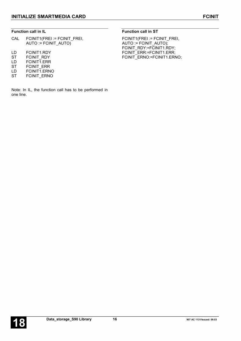
INITIALIZE SMARTMEDIA CARD FCINIT
Data_storage_S90 Library 16 907 AC 1131/Issued: 09.0318
Function call in ILCAL FCINIT1(FREI := FCINIT_FREI,
AUTO := FCINIT_AUTO)
LD FCINIT1.RDYST FCINIT_RDYLD FCINIT1.ERRST FCINIT_ERRLD FCINIT1.ERNOST FCINIT_ERNO
Note: In IL, the function call has to be performed inone line.
Function call in STFCINIT1(FREI := FCINIT_FREI,AUTO := FCINIT_AUTO);FCINIT_RDY:=FCINIT1.RDY;FCINIT_ERR:=FCINIT1.ERR;FCINIT_ERNO:=FCINIT1.ERNO;

READ DATA SET FROM SMARTMEDIA CARD FCRD
907 AC 1131/Issued: 09.03 17 Data_storage_S90 Library 18
READ DATA SET FROM SMARTMEDIA CARD FCRDThe function block reads a data set from a datasegment of the SmartMedia Card and stores the readdata set beginning at the start flag defined by SM.
Block dataAvailable as of PLC run-time system: V4.0 for 07 MC 90 R0101 (2 MB)
V5.0 for 07 MC 90 R0201 (8 MB)and 07 KT 9x R02xx
Remark:
Contained in library: ABB-BIB4.LIBDatenablage_S90_V41.LIB
Block typeFunction block with historical values
ParametersInstanz FCRD Instance nameFREI BOOL Storage of a data set by a FALSE/TRUE edgeNB INT Number of data set blocksSEG INT Number of the data segmentBNR INT Number of the block in the data segmentSM INT Start flag of the data setRDY BOOL Writing procedure completedERR BOOL Error has occurredERNO INT Error number
DescriptionThe function block reads a data set from a datasegment of the SmartMedia Card and stores the readdata set beginning at the start flag defined by SM.The data of the data set have been stored in theSmartMedia Card by the function block FCWR.
Important note:An access to the SmartMedia Card is only permittedby using the function blocks FCDEL, FCINIT, FCWRand FCRD.
The inputs SM and NB define which data are readfrom the SmartMedia Card. The input SEG definesthe SmartMedia Card data segment. The number ofdata which are read from a block depends on inputSM.
The following applies: 32 word data are read perblock. The data of each block are secured by achecksum.
The reading procedure of a data record is carried outonce by a FALSE/TRUE edge at input FREI. If noerror occurred when reading the data, output RDY isset to "TRUE" and the outputs ERR and ERNO areset to zero. The data set is stored beginning at thedefined start flag SM. Storing the data set can takeseveral PLC cycles.
If an error occurs during the reading procedure, RDYand ERR are both set to TRUE. The error type isindicated at output ERNO.
The outputs RDY, ERR and ERNO are set to zero bya zero signal at input FREI.

READ DATA SET FROM SMARTMEDIA CARD FCRD
Data_storage_S90 Library 18 907 AC 1131/Issued: 09.0318
FREI BOOLProcessing of the block is controlled via input FREI.
The following applies:
FREI = FALSE:The outputs RDY, ERR and ERNO are set to "0" or"FALSE", respectively.
FREI = FALSE/TRUE edge:The reading procedure of the data set is carried outonce.
FREI = TRUE:The block is not processed, i. e. it no longer changesits outputs.
NB INTThe number of the data set blocks is specified atinput NB. The number of data which are read from ablock depends on input SM. 32 word data are readper block.
Valid values: 1 ... 128
Example:
- SM = MW 02,00 / %MW1002.0 and NB = 1:Storing the data from MW 02,00 / %MW1002.0 toMW 03,15 / %MWW1003.15(1 block = 32 word data)
- SM = MW 02,00 / %MW1002.0 and NB = 2:Storing the data from MW 02,00 / %MW1002.0 toMW 05,15 / %MWW1005.15(2 blocks = 64 word data)
SEG INTThe number of the data segment of the SmartMediaCard is specified at input SEG. The following applies:
07 MC 90 R0101 (2 MB): 1...250
07 MC 90 R0201 (8 MB): 1...1023(as of run-time system V5.0 and 07 KT 9x R02xx)
BNR INTThe block number in the data segment is specified atinput BNR. Valid values: 0 ... 127
SM INTThe first INT flag for storing the data set is specifiedat input SM.
RDY BOOLOutput RDY indicates that reading the data recordhas been completed. This output has always to beconsidered together with output ERR.
The following applies:
RDY = TRUE and ERR = FALSE: The readingoperation has been completed. The data set is storedbeginning at the defined input SM.
RDY = TRUE and ERR = TRUE: An error occurredduring the reading procedure. Output ERNOsignalizes the error number.
ERR BOOLOutput ERR indicates whether an error occurredduring the reading operation. This output has alwaysto be considered together with output RDY. If an errorhas occurred, the following applies: RDY = TRUEand ERR = TRUE. Output ERNO signalizes the errornumber.
ERNO INTAt output ERNO an error number is output. Thisoutput has always to be considered together with theoutputs RDY and ERR.
The error number is binary encoded and valid for allFC* blocks. The following applies:
ERNO = 0 (bits 0...15 = 0):No error occurred
ERNO = 1 (bit 0 = 1):Block number and number of blocks is greaterthan 127.
ERNO = 2 (bit 1 = 1):Data segment is greater than maximum possible.
ERNO = 4 (bit 2 = 1):Block not programmable or check sum error.
ERNO = 8 (bit 3 = 1):Block already contains data.
ERNO = 16 (bit 4 = 1):Segment not deletable or too many defective blocks.
ERNO = 32 (bit 5 = 1):SmartMedia Card not initialized.
ERNO = 64 (bit 6 = 1):SmartMedia Card not inserted or wrong card.
ERNO = 128 (bit 7 = 1):The block is empty.
ERNO = 272 (bit 7 = 1 and bit 4 = 1):The card has too many defective blocks.
The inputs and outputs can neither be duplicated norinverted.

READ DATA SET FROM SMARTMEDIA CARD FCRD
907 AC 1131/Issued: 09.03 19 Data_storage_S90 Library 18
Function call in ILCAL FCRD1(FREI := FCRD_FREI,
NB := FCRD_NB, SEG := FCRD_SEG,BNR := FCRD_BNR, SM := FCRD_SM)
LD FCRD1.RDYST FCRD_RDYLD FCRD1.ERRST FCRD_ERRLD FCRD1.ERNOST FCRD_ERNO
Note: In IL, the function call has to be performed inone line.
Function call in STFCRD1(FREI := FCRD_FREI,NB := FCRD_NB, SEG := FCRD_SEG,BNR := FCRD_BNR, SM := FCRD_SM);FCRD_RDY:=FCRD1.RDY;FCRD_ERR:=FCRD1.ERR;FCRD_ERNO:=FCRD1.ERNO;

WRITE DATA SET TO SMARTMEDIA CARD FCWR
Data_storage_S90 Library 20 907 AC 1131/Issued: 09.0318
WRITE DATA SET TO SMARTMEDIA CARD FCWRThe function block writes a data set to a data segmentin the SmartMedia Card.
Block dataAvailable as of PLC run-time system: V4.0 for 07 MC 90 R0101 (2 MB)
V5.0 for 07 MC 90 R0201 (8 MB)and 07 KT 9x R02xx
Remark:
Contained in library: ABB-BIB4.LIBDatenablage_S90_V41.LIB
Block typeFunction block with historical values
ParametersInstance FCWR Instance nameFREI BOOL Storage of a data set by a FALSE/TRUE edgeNB INT Number of data set blocksSEG INT Number of the data segmentBNR INT Number of the block in the data segmentSM INT Start flag of the data setRDY BOOL Writing procedure completedERR BOOL Error has occurredERNO INT Error number
DescriptionThe function block writes a data set to a datasegment in the SmartMedia Card. A deletionprocedure (function block FCDEL) always deletes acomplete data segment. The following space isavailable on the card after formating:
07 MC 90 R0101 (2 MB):250 segments with 128 blocks of 64 bytes each, i.e.2000 kB can be stored in total.
07 MC 90 R0201 (8 MB):1023 segments with 128 blocks of 64 bytes each, i.e.8184 kB can be stored in total (as of run-time systemV5.0 and 07 KT 9x R02xx).
After deleting, each of this 128 blocks can be writtenonly once. If a block, already containing data, is to beoverwritten, the entire data segment must be deletedbeforehand.
When doing so, all data is lost in this data segment.
Important note:An access to the SmartMedia Card is only permittedby using the function blocks FCDEL, FCINIT, FCWRand FCRD.
The inputs SM and NB define which data are writtento the SmartMedia Card. The input SEG defines thedata segment in the SmartMedia Card. The numberof data which can be stored in a block depends oninput SM.
The following applies: 32 word data are written perblock. The data of each block are secured by achecksum.
When a writing procedure of a data set is started(FALSE/TRUE edge at input FREI), the data of thedata set must not be changed until the end of thewriting procedure (RDY = TRUE). Storing a data setin the SmartMedia Card can take several PLC cycles.
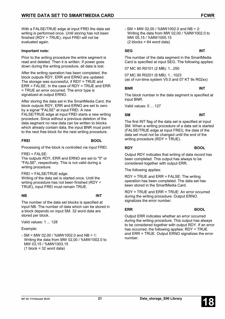
WRITE DATA SET TO SMARTMEDIA CARD FCWR
907 AC 1131/Issued: 09.03 21 Data_storage_S90 Library 18
With a FALSE/TRUE edge at input FREI the data setwriting is performed once. Until storing has not beenfinished (RDY = TRUE), input FREI will not beevaluated again.
Important note:Prior to the writing procedure the entire segment isread and deleted. Then it is written. If power goesdown during the writing procedure, all data is lost.
After the writing operation has been completed, theblock outputs RDY, ERR and ERNO are updated.The storage was successful, if RDY = TRUE andERR = FALSE. In the case of RDY = TRUE and ERR= TRUE an error occurred. The error type issignalized at output ERNO.
After storing the data set in the SmartMedia Card, theblock outputs RDY, ERR and ERNO are set to zeroby a signal "FALSE" at input FREI. A newFALSE/TRUE edge at input FREI starts a new writingprocedure. Since without a previous deletion of thedata segment no new data can be written to blockswhich already contain data, the input BNR must pointto the next free block for the next writing procedure.
FREI BOOLProcessing of the block is controlled via input FREI.
FREI = FALSE:The outputs RDY, ERR and ERNO are set to "0" or"FALSE", respectively. This is not valid during awriting procedure.
FREI = FALSE/TRUE edge:Writing of the data set is started once. Until thewriting procedure has not been finished (RDY =TRUE), input FREI must remain TRUE.
NB INTThe number of the data set blocks is specified atinput NB. The number of data which can be stored ina block depends on input SM. 32 word data arestored per block.
Valid values: 1 ... 128
Example:
- SM = MW 02,00 / %MW1002.0 and NB = 1:Writing the data from MW 02,00 / %MW1002.0 toMW 03,15 / %MW1003.15(1 block = 32 word data)
- SM = MW 02,00 / %MW1002.0 and NB = 2:Writing the data from MW 02,00 / %MW1002.0 toMW 05,15 / %MW1005.15(2 blocks = 64 word data)
SEG INTThe number of the data segment in the SmartMediaCard is specified at input SEG. The following applies:
07 MC 90 R0101 (2 MB): 1...250
07 MC 90 R0201 (8 MB): 1...1023(as of run-time system V5.0 and 07 KT 9x R02xx)
BNR INTThe block number in the data segment is specified atinput BNR.
Valid values: 0 ... 127
SM INTThe first INT flag of the data set is specified at inputSM. When a writing procedure of a data set is started(FALSE/TRUE edge at input FREI), the data of thedata set must not be changed until the end of thewriting procedure (RDY = TRUE).
RDY BOOLOutput RDY indicates that writing of data record hasbeen completed. This output has always to beconsidered together with output ERR.
The following applies:
RDY = TRUE and ERR = FALSE: The writingoperation has been completed. The data set hasbeen stored in the SmartMedia Card.
RDY = TRUE and ERR = TRUE: An error occurredduring the writing procedure. Output ERNOsignalizes the error number.
ERR BOOLOutput ERR indicates whether an error occurredduring the writing procedure. This output has alwaysto be considered together with output RDY. If an errorhas occurred, the following applies: RDY = TRUEand ERR = TRUE. Output ERNO signalizes the errornumber.

WRITE DATA SET TO SMARTMEDIA CARD FCWR
Data_storage_S90 Library 22 907 AC 1131/Issued: 09.0318
ERNO INTAt output ERNO an error number is output. Thisoutput has always to be considered together with theoutputs RDY and ERR.
The error number is binary encoded and valid for allFC* blocks.The following applies:
ERNO = 0 (bits 0...15 = 0):No error occurred
ERNO = 1 (bit 0 = 1):Block number and number of blocks is greaterthan 127.
ERNO = 2 (bit 1 = 1):Data segment is greater than maximum possible.
ERNO = 4 (bit 2 = 1):Block not programmable or check sum error.
ERNO = 8 (bit 3 = 1):Block already contains data.
ERNO = 16 (bit 4 = 1):Segment not deletable or too many defective blocks.
ERNO = 32 (bit 5 = 1):SmartMedia Card not initialized.
ERNO = 64 (bit 6 = 1):SmartMedia Card not inserted or wrong card.
ERNO = 128 (bit 7 = 1):Block is empty.
ERNO = 272 (bit 7 = 1 and bit 4 = 1):The card has too many defective blocks.
The inputs and outputs can neither be duplicated norinverted.
Function call in ILCAL FCWR1(FREI := FCWR_FREI,
NB := FCWR_NB, SEG := FCWR_SEG,BNR := FCWR_BNR, SM := FCWR_SM)
LD FCWR1.RDYST FCWR_RDYLD FCWR1.ERRST FCWR_ERRLD FCWR1.ERNOST FCWR_ERNO
Note: In IL, the function call has to be performed inone line.
Function call in STFCWR1(FREI := FCWR_FREI,NB := FCWR_NB, SEG := FCWR_SEG,BNR := FCWR_BNR, SM := FCWR_SM);FCWR_RDY:=FCWR1.RDY;FCWR_ERR:=FCWR1.ERR;FCWR_ERNO:=FCWR1.ERNO;
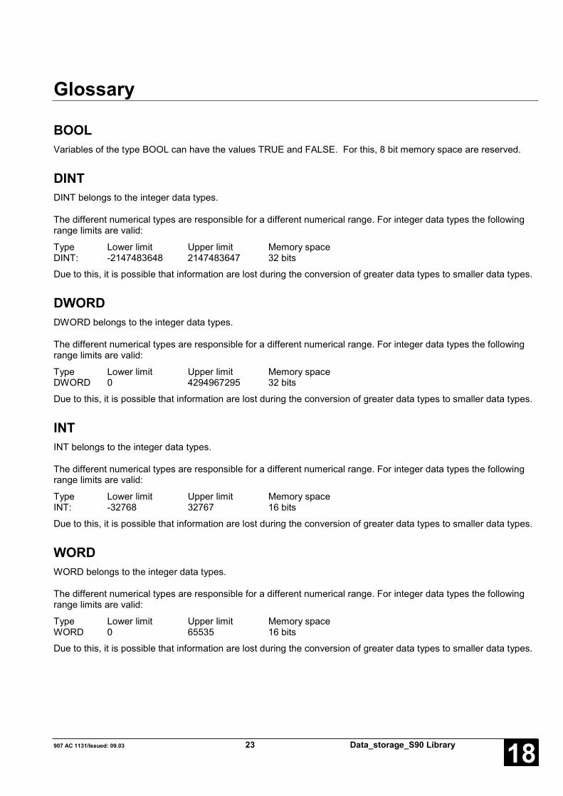
907 AC 1131/Issued: 09.03 23 Data_storage_S90 Library 18
Glossary
BOOLVariables of the type BOOL can have the values TRUE and FALSE. For this, 8 bit memory space are reserved.
DINTDINT belongs to the integer data types.
The different numerical types are responsible for a different numerical range. For integer data types the followingrange limits are valid:
Type Lower limit Upper limit Memory spaceDINT: -2147483648 2147483647 32 bits
Due to this, it is possible that information are lost during the conversion of greater data types to smaller data types.
DWORDDWORD belongs to the integer data types.
The different numerical types are responsible for a different numerical range. For integer data types the followingrange limits are valid:
Type Lower limit Upper limit Memory spaceDWORD 0 4294967295 32 bits
Due to this, it is possible that information are lost during the conversion of greater data types to smaller data types.
INTINT belongs to the integer data types.
The different numerical types are responsible for a different numerical range. For integer data types the followingrange limits are valid:
Type Lower limit Upper limit Memory spaceINT: -32768 32767 16 bits
Due to this, it is possible that information are lost during the conversion of greater data types to smaller data types.
WORDWORD belongs to the integer data types.
The different numerical types are responsible for a different numerical range. For integer data types the followingrange limits are valid:
Type Lower limit Upper limit Memory spaceWORD 0 65535 16 bits
Due to this, it is possible that information are lost during the conversion of greater data types to smaller data types.

Data_storage_S90 Library 24 907 AC 1131/Issued: 09.0318
FunctionsFunctions are subroutines which have multiple input parameters and return exactly one result element. Thereturned result can be of an elementary or a derived data type. Due to this, a function may also return an array, astructure, an array of structures and so on.
For the same input parameters, functions always return the same result (they do not have an internal memory).
Therefore, the following rules can derived:
• Within functions, global variables can neither be read nor written.• Within functions, it is not allowed to read or write absolute operands.• Within functions, it is not allowed to call function blocks.
Function blocksFunction blocks are subroutines which can have as much inputs, outputs and internal variables as required. Theyare called by a program or by another function block.
As they can be used several times (with different data records), function blocks (code and interface) can beconsidered as type. When assigning an individual data record (declaration) to the function block, a function blockinstance is generated.
In contrast to functions, function blocks can contain statically local data which are saved from one call to the next.This allows for example to realize counters which may not forget their counter value. I.e. function blocks can havean internal memory.
Functions and function blocks differ in two essential points:
• A function block has multiple output parameters. A function has maximally one output parameter. Note thatthe output parameters of functions and function blocks differ syntactically.
• In contrast to a function, a function block can have an internal memory.
1. Function blocks with historical values (memory):
For function blocks with historical values it has to be observed that instance names may not be defined severaltimes if different data sets should be called.
2. Function blocks without historical values (memory):
For function blocks without historical values only one instance has to be defined for the FB type. This instance canbe used for several calls of the FB (also with different I/O values).
The instance name can be defined without any restrictions. The type is preset and identical to the function blockname.

907 AC 1131/Issued: 09.03 25 Data_storage_S90 Library 18
Index
CCOMPONENTS OF THE DATA STORAGE
LIBRARY 2
DData storage S90
FCDEL 11
FCINIT 14
FCRD 17
FCWR 20
FDEL 3
FRD 5
FWR 8
FFCDEL S90 11
FCINIT S90 14
FCRD S90 17
FCWR S90 20
FDEL S90 3
FRD S90 5
FWR S90 8

Data_storage_S90 Library 26 907 AC 1131/Issued: 09.0318

Software Description Advant Controller 31Intelligent DecentralizedAutomation System
Function Blocksfor System Information90 Series
System Info90 Series

907 AC 1131/Issued: 09.03 1 System Info_S90 Library 18
Contents
The System Info Library 2PRECONDITION FOR THE USE OF THE SYSTEM INFO LIBRARY ................................. 2COMPONENTS OF THE SYSTEM INFO LIBRARY ................................. 2
Block overview arranged according to their call names 2INTERROGATION OF INFORMATION ABOUT THE USERPROGRAMM STACK GET_STACKINFO ... 3INTERROGATION OF INFORMATION ABOUT THE HEAP HEAP_INFO............. 4INTERROGATION OF INFORMATION ABOUT THE PLC IDENT....................... 6INTERROGATION OF INFORMATION ABOUT THE USERPROGRAM PROJEKTINFO ........ 8READING THE SYSTEM TIME SYS_TIME................ 9INTERROGATION, WHETHER AN EXCEPTION OCCURREDDURING FLOATING-POINT CALCULATION FPUEXINFO........... 10INTERROGATION OF THE STARTING ADDRESSES OF THEDUAL-PORT RAM HW_INFO .............. 12
Glossary 14
Index 16
THE SYSTEM INFO LIBRARY
System Info_S90 Library 2 907 AC 1131/Issued: 09.0318
The System Info LibraryPRECONDITION FOR THE USE OF THE SYSTEM INFO LIBRARYNote:
The blocks of the System Info Library only run in the RUN mode of the PLC, not in the simulation mode.
COMPONENTS OF THE SYSTEM INFO LIBRARY
The following function blocks are contained in the System Info Library:
GET_STACKINFO - Interrogation of information about the user program stack
HEAP_INFO - Interrogation of information about the heap
IDENT - Interrogation of information about the PLC
PROJEKTINFO - Interrogation of information about the user program
SYS_TIME - Reading the system time
FPUEXINFO - Interrogation, whether an exception occurred during floating-point calculation
HW_INFO - Interrogation of the starting addresses of the dual-port RAM
Detailed descriptions of the blocks can be found in the following sections.
Block overview arranged according to their call names
Explanation of the abbreviations:
FBmV … Function block with historical values
FBoV … Function block without historical values
F … Function
CE Name Type Function Page
FPUEXINFO FBoV Interrogation, whether an exception occurred during floating-pointcalculation
10
GET_STACKINFO FBoV Interrogation of information about the user program stack 3
HEAP_INFO FBoV Interrogation of information about the heap 4
HW_INFO FBoV Interrogation of the starting addresses of the dual-port RAM 12
IDENT FBoV Interrogation of information about the PLC 6
PROJEKTINFO F Interrogation of information about the user program 8
SYS_TIME F Reading the system time 9
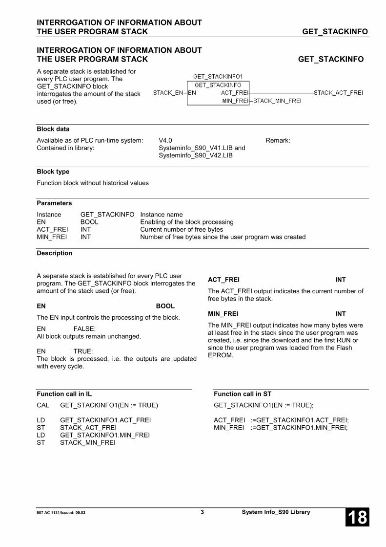
INTERROGATION OF INFORMATION ABOUTTHE USER PROGRAM STACK GET_STACKINFO
907 AC 1131/Issued: 09.03 3 System Info_S90 Library 18
INTERROGATION OF INFORMATION ABOUTTHE USER PROGRAM STACK GET_STACKINFOA separate stack is established forevery PLC user program. TheGET_STACKINFO blockinterrogates the amount of the stackused (or free).
Block dataAvailable as of PLC run-time system: V4.0 Remark:Contained in library: Systeminfo_S90_V41.LIB and
Systeminfo_S90_V42.LIB
Block typeFunction block without historical values
ParametersInstance GET_STACKINFO Instance nameEN BOOL Enabling of the block processingACT_FREI INT Current number of free bytesMIN_FREI INT Number of free bytes since the user program was created
Description
A separate stack is established for every PLC userprogram. The GET_STACKINFO block interrogates theamount of the stack used (or free).
EN BOOLThe EN input controls the processing of the block.
EN FALSE:All block outputs remain unchanged.
EN TRUE:The block is processed, i.e. the outputs are updatedwith every cycle.
ACT_FREI INTThe ACT_FREI output indicates the current number offree bytes in the stack.
MIN_FREI INTThe MIN_FREI output indicates how many bytes wereat least free in the stack since the user program wascreated, i.e. since the download and the first RUN orsince the user program was loaded from the FlashEPROM.
Function call in ILCAL GET_STACKINFO1(EN := TRUE)
LD GET_STACKINFO1.ACT_FREIST STACK_ACT_FREILD GET_STACKINFO1.MIN_FREIST STACK_MIN_FREI
Function call in STGET_STACKINFO1(EN := TRUE);
ACT_FREI :=GET_STACKINFO1.ACT_FREI;MIN_FREI :=GET_STACKINFO1.MIN_FREI;

INTERROGATION OF INFORMATION ABOUT THE HEAP HEAP_INFO
System Info_S90 Library 4 907 AC 1131/Issued: 09.0318
INTERROGATION OF INFORMATION ABOUT THE HEAP HEAP_INFOThis block enables the user to get informationabout the heap.
Block dataAvailable as of PLC run-time system: V4.0 Remark:Contained in library: Systeminfo_S90_V41.LIB and
Systeminfo_S90_V42.LIB
Block typeFunction block without historical values
ParametersInstance HEAP_INFO Instance nameTotalFree DWORD Total amount of memory space, currently freeTotalUsed DWORD Total amount of memory space, currently usedFreeBlocks DWORD Number of free blocksUsedBlocks DWORD Number of reserved blocksLargestBlock DWORD Largest coherent free memory space
DescriptionThe heap is an area in the RAM usable for theoperating system for varying tasks (and varying need ofspace), i.e. this area is not allocated at the beginning.For instance, the tasks "Send program" or "Onlinechange" use memory space temporarily in the heapand free the space again after use.
The ARCNET blocks also reserve memory space in theheap for buffers temporarily used. For the newARCNET blocks, the size of these buffers is user-defined.
Since depending on the application (e.g. how manyPLC tasks were created) the free memory space isdifferent in size, the HEAP_INFO function block can beused to find out the size of free memory in the heap.
The heap can be more or less fragmented, i.e. it ispossible that there are 20 Kbytes free in total, but thereis no coherent memory space of 20 Kbytes for creatingsuch a block.
If more memory space is demanded than really exists,an error is output (FK3 - error code 181).

INTERROGATION OF INFORMATION ABOUT THE HEAP HEAP_INFO
907 AC 1131/Issued: 09.03 5 System Info_S90 Library 18
TotalFree DWORDThe TotalFree output indicates the total amount offree memory space in bytes currently available.
TotalUsed DWORDThe TotalUsed output indicates the total amount ofcurrently used memory space in bytes.
FreeBlocks DWORDThe FreeBlocks output indicates the number of freeblocks.
UsedBlocks DWORDThe UsedBlocks output indicates the number ofreserved (used) blocks.
LargestFree DWORDThe LargestFree output indicates the largestcoherent free memory space in bytes.
Function call in IL
CAL HEAP_INFO1()
LD HEAP_INFO1.TotalFreeST TotalFree
LD HEAP_INFO1.TotalUsedST TotalUsed
LD HEAP_INFO1.FreeBlocksST FreeBlocks
LD HEAP_INFO1.UsedBlocksST UsedBlocks
LD HEAP_INFO1.LargestFreeST LargestFree
Function call in ST
HEAP_INFO1();
TotalFree := HEAP_INFO1.TotalFree
TotalUsed := HEAP_INFO1.TotalUsed
FreeBlocks := HEAP_INFO1.FreeBlocks
UsedBlocks := HEAP_INFO.UsedBlocks
LargestFree := HEAP_INFO.LargestFree

INTERROGATION OF INFORMATION ABOUT THE PLC IDENT
System Info_S90 Library 6 907 AC 1131/Issued: 09.0318
INTERROGATION OF INFORMATION ABOUT THE PLC IDENTThe IDENT function block supplies informationabout the PLC from which the PLC program wasstarted.
Block dataAvailable as of PLC run-time system: V4.0 Remark:Contained in library: Systeminfo_S90_V41.LIB and
Systeminfo_S90_V42.LIB
Block typeFunction block without historical values
ParametersInstance IDENT Instance nameFREI BOOL Enabling of the block processingTYP INT PLC typeRUB INT PLC versionVER INT Software version as a 3-digit number
DescriptionThe IDENT function block supplies information aboutthe PLC from which the PLC program was started.
FREI BOOLEnabling for block processing.
FREI TRUEIf FREI = TRUE, the outputs of the block areupdated.
FREI FALSEThe block is not processed. The outputs remainunchanged.
TYP INTIf FREI = TRUE, the TYP output indicates the PLCtype.
95 means 07 KT 9596 means 07 KT 9697 means 07 KT 97 or 07 SL 9798 means 07 KT 98
VER INTThe VER output indicates the software version as a3-digit number: e.g. 416 means Version V4.16.
RUB INTThe RUB output indicates the PLC version R0xxx:
Version PLC, equipped with the couplers...
100 / 200 no internal couplers
120 / 220 PROFIBUS DP coupler
160 / 260 ARCNET coupler
162 / 262 ARCNET + PROFIBUS DP coupler
165 / 265 ARCNET + DeviceNet coupler
268 ARCNET + CANopen coupler
270 Ethernet coupler
272 Ethernet + PROFISUB DP coupler
276 Ethernet + ARCNET coupler
278 Ethernet + CANopen coupler
280 CANopen coupler
INTERROGATION OF INFORMATION ABOUT THE PLC IDENT
907 AC 1131/Issued: 09.03 7 System Info_S90 Library 18
Function call in ILCAL IDENT1(FREI := TRUE)
LD IDENT1.TYPST IDENT_TYP
LD IDENT1.RUBST IDENT_RUB
LD IDENT1.VERST IDENT_VER
Function call in ST
IDENT1(FREI := TRUE);
IDENT_TYP := IDENT1.TYP;IDENT_RUB := IDENT1.RUB;IDENT_VER := IDENT1.VER;
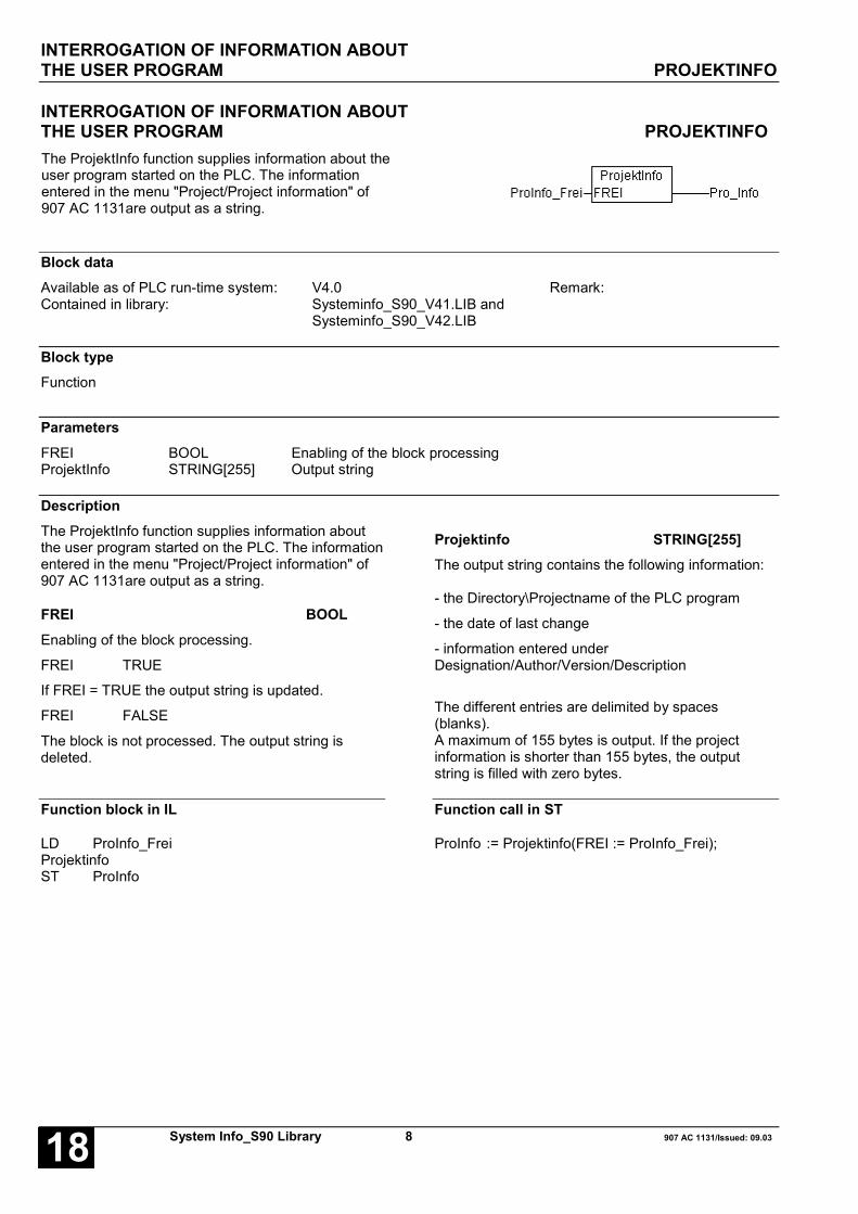
INTERROGATION OF INFORMATION ABOUTTHE USER PROGRAM PROJEKTINFO
System Info_S90 Library 8 907 AC 1131/Issued: 09.0318
INTERROGATION OF INFORMATION ABOUTTHE USER PROGRAM PROJEKTINFOThe ProjektInfo function supplies information about theuser program started on the PLC. The informationentered in the menu "Project/Project information" of907 AC 1131are output as a string.
Block dataAvailable as of PLC run-time system: V4.0 Remark:Contained in library: Systeminfo_S90_V41.LIB and
Systeminfo_S90_V42.LIB
Block typeFunction
ParametersFREI BOOL Enabling of the block processingProjektInfo STRING[255] Output string
DescriptionThe ProjektInfo function supplies information aboutthe user program started on the PLC. The informationentered in the menu "Project/Project information" of907 AC 1131are output as a string.
FREI BOOLEnabling of the block processing.
FREI TRUE
If FREI = TRUE the output string is updated.
FREI FALSE
The block is not processed. The output string isdeleted.
Projektinfo STRING[255]The output string contains the following information:
- the Directory\Projectname of the PLC program
- the date of last change
- information entered underDesignation/Author/Version/Description
The different entries are delimited by spaces(blanks).A maximum of 155 bytes is output. If the projectinformation is shorter than 155 bytes, the outputstring is filled with zero bytes.
Function block in IL
LD ProInfo_FreiProjektinfoST ProInfo
Function call in ST
ProInfo := Projektinfo(FREI := ProInfo_Frei);

READING THE SYSTEM TIME SYS_TIME
907 AC 1131/Issued: 09.03 9 System Info_S90 Library 18
READING THE SYSTEM TIME SYS_TIMEThe SYS_TIME function supplies the system tick as adouble word in milliseconds.
Block dataAvailable as of PLC run-time system: V4.0 Remark:Contained in library: Systeminfo_S90_V41.LIB and
Systeminfo_S90_V42.LIB
Block typeFunction
ParametersFREI BOOL Enabling of the block processingSYS_TIME DWORD System tick in ms
DescriptionThe SYS_TIME function supplies the system tick as adouble word. The system tick is resolved intomilliseconds. Among other things, the system tick isused as time base for both the user program and alltime-dependent function blocks. After a RESET, thesystem tick begins counting with 0. The first overflowis reached after 49 days. With an overflow, thecounter begins at 0 again.
FREI BOOLEnabling of the block processing.
FREI TRUE
If FREI = TRUE, the block output is updated.
FREI FALSE
The block is not processed. The output remainsunchanged since the program start.
SYS_TIME DWORDSystem tick in milliseconds.
Function call in IL
LD TRUESYS_TIMEST Systemtick
Function call in ST
Systemtick =: SYS_TIME(FREI := TRUE);

INTERROGATION, WHETHER AN EXCEPTION OCCURRED DURINGFLOATING-POINT CALCULATION FPUEXINFO
System Info_S90 Library 10 907 AC 1131/Issued: 09.0318
INTERROGATION, WHETHER AN EXCEPTION OCCURRED DURINGFLOATING-POINT CALCULATION FPUEXINFOUsing the FPUEXINFO functionblock, it can be found out whetheran exception occurred during afloating-point calculation.
Block dataAvailable as of PLC run-time system: V4.16 Remark:Contained in library: Systeminfo_S90_V42.LIB
Block typeFunction block without historical values
ParametersInstanz FPUEXINFO Instance nameERR BOOL ERR=TRUE: Exception after floating-point calculationINFO STRING(255) Information about the calculation
DescriptionUsing the FPUEXINFO function block, it can be foundout whether an exception occurred during a floating-point calculation. The setting of the reaction tofloating-point exceptions is performed with thesystem constant KW81,08 / %MW3081.8.
The following applies:
KW81_08 AT %MW3081.8 : INT := 0; (* default *)- The FK2 error 182Dec = B6Hex is triggered with afloating-point exception (e.g. with SQRT(-1)). ThePLC turns to STOP. Using the calling hierarchy of the907 AC 1131, it can be found out where the erroroccurred.
KW81_08 AT %MW3081.8 : INT := 1;In case of a floating-point exception, no error istriggered. Using the FPUEXINFO function block, itcan be found out, whether an floating-point exceptionoccurred within the calculation. The user can nowdecide, whether to continue with default values or toshut down the machine specifically.
ERR BOOLThe ERR output indicates whether a floating-pointexception has occurred.
ERR=TRUE
The previous calculation has triggered a floating-pointexception.
ERR=FALSE
The previous calculation did not trigger a floating-point exception.
INFO STRING(255)The INFO output string supplies further informationabout the calculation.
.
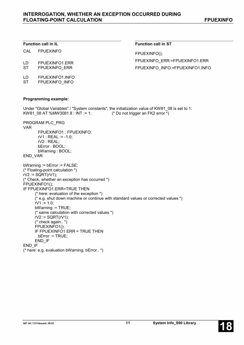
INTERROGATION, WHETHER AN EXCEPTION OCCURRED DURINGFLOATING-POINT CALCULATION FPUEXINFO
907 AC 1131/Issued: 09.03 11 System Info_S90 Library 18
Function call in ILCAL FPUEXINFO
LD FPUEXINFO1.ERRST FPUEXINFO_ERR
LD FPUEXINFO1.INFOST FPUEXINFO_INFO
Function call in ST
FPUEXINFO();
FPUEXINFO_ERR:=FPUEXINFO1.ERR
FPUEXINFO_INFO:=FPUEXINFO1.INFO
Programming example:
Under "Global Variables" / "System constants", the initialization value of KW81_08 is set to 1:KW81_08 AT %MW3081.8 : INT := 1; (* Do not trigger an FK2 error *)
PROGRAM PLC_PRGVAR
FPUEXINFO1 : FPUEXINFO;rV1 : REAL := -1.0;rV2 : REAL;bError : BOOL;bWarning : BOOL;
END_VAR
bWarning := bError := FALSE;(* Floating-point calculation *)rV2 := SQRT(rV1);(* Check, whether an exception has occurred *)FPUEXINFO1();IF FPUEXINFO1.ERR=TRUE THEN
(* here: evaluation of the exception *)(* e.g. shut down machine or continue with standard values or corrected values *)rV1 := 1.0;bWarning := TRUE;(* same calculation with corrected values *)rV2 := SQRT(rV1);(* check again.. *)FPUEXINFO1();IF FPUEXINFO1.ERR = TRUE THEN
bError := TRUE;END_IF
END_IF(* here: e.g. evaluation bWarning, bError.. *)

INTERROGATION OF THE STARTING ADDRESSESOF THE DUAL-PORT RAM HW_INFO
System Info_S90 Library 12 907 AC 1131/Issued: 09.0318
INTERROGATION OF THE STARTING ADDRESSESOF THE DUAL-PORT RAM HW_INFOThe HW_INFO functionblock supplies the startaddresses of the dual-port RAM (DPR) of thePLC.
Block dataAvailable as of PLC runtime system: V4.16 Remark:Contained in library: Systeminfo_S90_V42.LIB
Block typeFunction block without historical values
ParametersInstanz HW_INFO Instance nameEN BOOL Enabling of the block processingDPR_EXT DWORD Start address of the DPR of the external networking interfaceDPR_EA DWORD Start address of the DPR of the onboard IO processorDPR_CS31 DWORD Start address of the DPR of the CS31 bus processorDPR_INT DWORD Start address of the DPR of the internal couplers
DescriptionThe HW_INFO function block supplies the startaddresses of the dual-port RAM (DPR) of the PLC.
EN BOOLEnabling of the block processing.
FREI TRUE
If FREI = TRUE, the block outputs are updated.
FREI FALSE
The block is not processed. The outputs remainunchanged since the program start.
DPR_EXT DWORDAt the DPR_EXT output the start address of the dual-port RAM of the external networking interface isavailable.
DPR_EA DWORDAt the DPR_EA output the start address of the dual-port RAM of the onboard IO processor is available.
DPR_CS31 DWORDAt the DPR_CS31 output the start address of thedual-port RAM of the CS31 bus processor isavailable.
DPR_INT DWORDAt the DPR_INT output the start address of the dual-port RAM of the internal couplers is available.

INTERROGATION OF THE STARTING ADDRESSESOF THE DUAL-PORT RAM HW_INFO
907 AC 1131/Issued: 09.03 13 System Info_S90 Library 18
Function call in ILCAL HW_INFO(EN := TRUE)
LD HW_INFO1.DPR_EXTST HW_INFO_DPR_EXT
LD HW_INFO1.DPR_EAST HW_INFO_DPR_EA
LD HW_INFO1.DPR_CS31ST HW_INFO_DPR_CS31
LD HW_INFO1.DPR_INTST HW_INFO_DPR_INT
Function call in ST
HW_INFO1(EN := TRUE);
HW_INFO_DPR_EXT := HW_INFO1.DPR_EXT
HW_INFO_DPR_EA := HW_INFO1.DPR_EA
HW_INFO_DPR_CS31 := HW_INFO1.DPR_CS31
HW_INFO_DPR_INT := HW_INFO1.DPR_INT
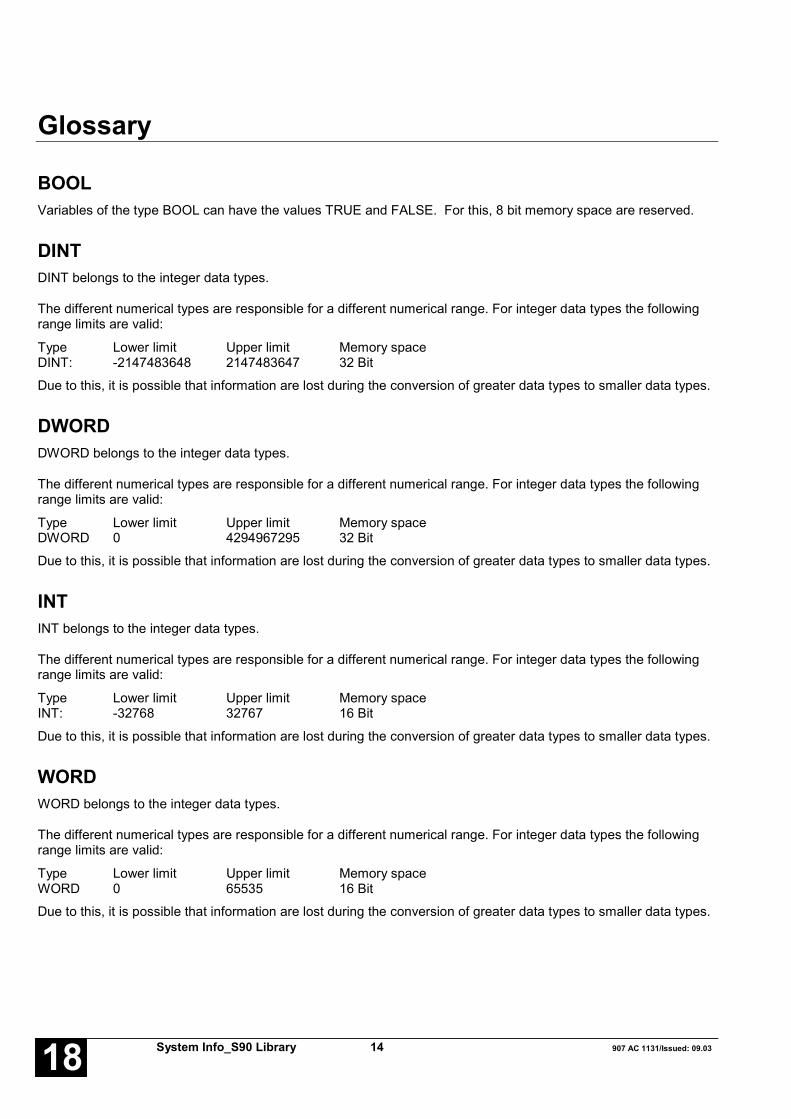
System Info_S90 Library 14 907 AC 1131/Issued: 09.0318
Glossary
BOOLVariables of the type BOOL can have the values TRUE and FALSE. For this, 8 bit memory space are reserved.
DINTDINT belongs to the integer data types.
The different numerical types are responsible for a different numerical range. For integer data types the followingrange limits are valid:
Type Lower limit Upper limit Memory spaceDINT: -2147483648 2147483647 32 Bit
Due to this, it is possible that information are lost during the conversion of greater data types to smaller data types.
DWORDDWORD belongs to the integer data types.
The different numerical types are responsible for a different numerical range. For integer data types the followingrange limits are valid:
Type Lower limit Upper limit Memory spaceDWORD 0 4294967295 32 Bit
Due to this, it is possible that information are lost during the conversion of greater data types to smaller data types.
INTINT belongs to the integer data types.
The different numerical types are responsible for a different numerical range. For integer data types the followingrange limits are valid:
Type Lower limit Upper limit Memory spaceINT: -32768 32767 16 Bit
Due to this, it is possible that information are lost during the conversion of greater data types to smaller data types.
WORDWORD belongs to the integer data types.
The different numerical types are responsible for a different numerical range. For integer data types the followingrange limits are valid:
Type Lower limit Upper limit Memory spaceWORD 0 65535 16 Bit
Due to this, it is possible that information are lost during the conversion of greater data types to smaller data types.

907 AC 1131/Issued: 09.03 15 System Info_S90 Library 18
FunctionsFunctions are subroutines which have multiple input parameters and return exactly one result element. Thereturned result can be of an elementary or a derived data type. Due to this, a function may also return an array, astructure, an array of structures and so on.
For the same input parameters, functions always return the same result (they do not have an internal memory).
Therefore, the following rules can derived:
• Within functions, global variables can neither be read nor written.• Within functions, it is not allowed to read or write absolute operands.• Within functions, it is not allowed to call function blocks.
Function blocksFunction blocks are subroutines which can have as much inputs, outputs and internal variables as required. Theyare called by a program or by another function block.
As they can be used several times (with different data records), function blocks (code and interface) can beconsidered as type. When assigning an individual data record (declaration) to the function block, a function blockinstance is generated.
In contrast to functions, function blocks can contain statically local data which are saved from one call to the next.This allows for example to realize counters which may not forget their counter value. I.e. function blocks can havean internal memory.
Functions and function blocks differ in two essential points:
• A function block has multiple output parameters. A function has maximally one output parameter. Note thatthe output parameters of functions and function blocks differ syntactically.
• In contrast to a function, a function block can have an internal memory.
1. Function blocks with historical values (memory):
For function blocks with historical values it has to be observed that instance names may not be defined severaltimes if different data sets should be called.
2. Function blocks without historical values (memory):
For function blocks without historical values only one instance has to be defined for the FB type. This instance canbe used for several calls of the FB (also with different I/O values).
The instance name can be defined without any restrictions. The type is preset and identical to the function blockname.

System Info_S90 Library 16 907 AC 1131/Issued: 09.0318
Index
CComponents of the System Info Library 2
FFPUEXINFO S90 10
GGET_STACKINFO S90 3
HHEAP_INFO S90 4
HW_INFO S90 12
IIDENT S90 6
PProjektinfo S90 8
SSYS_TIME S90 9
SystemInfo S90
FPUEXINFO 10
GET_STACKINFO 3
HEAP_INFO 4
HW_INFO 12
IDENT 6
Projektinfo 8
SYS_TIME 9

Software Description Advant Controller 31Intelligent DecentralizedAutomation System
PROFIBUSFunction Block Library90 Series
PROFIBUS90 Series


907 AC 1131/Issued: 07.02 1 PROFIBUS_S90 Library 18
Contents
The PROFIBUS library 2PREREQUISITES FOR THE USAGE OF THE LIBRARY 2COMPONENTS OF THE LIBRARIES 2PROFIBUS-DP MASTER 3PROFIBUS-DP SLAVE 4ERR - ERROR MESSAGES OF THE PROFIBUS BLOCKS 5
Overview of blocks arranged according to their call names 6READING OUT INFORMATION ABOUTTHE INSTALLED PROFIBUS COUPLERS PROFI_INFO 7POLLING DETAILED DIAGNOSTIC DATAOF A DP SLAVE DPM_SLVDIAG 10READING OUT THE PROFIBUS COUPLER STATUS DPM_STAT 19READING OUT THE STATUS SURVEY OF ALLDP SLAVES DPM_SYSDIAG 25SENDING GLOBAL CONTROL COMMANDSTO THE DP SLAVE DPM_CTRL 27SENDING USER PARAMETERS TO A DP SLAVE DPM_SETPRM 32READING THE INPUT DATA OF A SLAVE WHICHIS NOT ASSIGNED TO THE MASTER DPM_READ_INPUT 34READING THE OUTPUT DATA OF A SLAVEWHICH IS NOT ASSIGNED TO THE MASTER DPM_READ_OUTPUT 36READING OUT THE STATUS OF THEPROFIBUS COUPLER DPS_STAT 38SENDING THE ERROR FLAGS OF THE BASICUNIT FOR AN EXTENDED DIAGNOSIS DPS_EXTDIAG 42READING OUT THE USER PARAMETERS DPS_GETPRM 45
Glossary 49
Index 51

THE PROFIBUS LIBRARY
PROFIBUS_S90 Library 2 907 AC 1131/Issued: 07.0218
The PROFIBUS libraryPREREQUISITES FOR THE USAGE OF THE LIBRARYThe PROFIBUS couplers of the AC31 series 90 controllers can be operated as DP master or as DP slave(exception: 07 SL 97 can only be used as DP master). Up to version V4.2 (incl.) the function blocks for bothoperation modes were summarized in one common 907 AC 1131 library named PROFIBUS_S90_VXX.LIB.Because version V4.3 contains additional new function blocks, the libraries are now divided toPROFIBUS_Master_S90_VXX.LIB and PROFIBUS_Slave_S90_VXX.LIB according to the operation mode. Thelibrary PROFIBUS_S90_VXX.LIB can still be used, if only the functions contained in this library are used withinexisting projects. However, it is recommended to include the new PROFIBUS library according to the usedoperation mode instead of using the old common library. For new projects, only the new libraries should be usedwhich are separated according to the operation mode.
The function blocks contained in the PROFIBUS libraries access to both, the PLC run time system and directly tothe coupler. The definitions and functions required for this are stored in the internal libraryCOUPLER_S90_V41.LIB.
When using the PROFIBUS libraries, the library COUPLER_S90_V41.LIB must be included additionally inthe project.Note:
Neither the blocks of the PROFIBUS library nor the PROFIBUS communication can run in simulation mode. ThePROFIBUS communication only runs in the RUN mode of the PLC, not with single cycle, step and breakpoint.
COMPONENTS OF THE LIBRARIESFor normal cyclic data exchange via PROFIBUS-DP it is not necessary to include the libraries. The libraries containadditional function blocks which allow an easy handling of the PROFIBUS coupler in the indvidual operationmodes. Additionally, various data types are defined in this library. These structures enable a clear presentation ofdata sets.

THE PROFIBUS LIBRARY
907 AC 1131/Issued: 07.02 3 PROFIBUS_S90 Library 18
PROFIBUS-DP MASTER
Function blocks
The library PROBIBUS_Master_S90_Vxx.LIB contains the following function blocks:
Group: GeneralPROFI_INFO - Reading information about the installed couplers
Group: Status / DiagnosticsDPM_SLVDIAG - Polling diagnostic data from a DP slave
DPM_STAT - Reading out the state of the PROFIBUS coupler operating as DP master
DPM_SYSDIAG - Displaying status surveys of all DP slaves
Group: Control systemDPM_CTRL - Sending control commands to the DP slaves
Group: ParametersDPM_SETPRM - Sending user parameters to a DP slave during runtime
Group: Acyclic reading of I/O dataDPM_READ_INPUT - Reading the input data of a slave which is not assigned to the master
DPM_READ_OUTPUT - Reading the output data of a slave which is not assigned to the master
Detailed information about the various blocks can be found in the following sections.
Data types
In the library for the operation mode PROFIBUS-DP master the following data types (structures) are defined:
DPM_COM_ERR_TYPE - Communication error
DPM_STATE_BITS_TYPE - Bits for coupler state description
STATIONSTATUS_1_TYPE - Stationstatus_1 (DP slave diagnosis according to standard)
STATIONSTATUS_2_TYPE - Stationstatus_2 (DP slave diagnosis according to standard)
STATIONSTATUS_3_TYPE - Stationstatus_3 (DP slave diagnosis according to standard)
For detailed information about the different data types please refer to the particular description of the correspondingblock.
THE PROFIBUS LIBRARY
PROFIBUS_S90 Library 4 907 AC 1131/Issued: 07.0218
PROFIBUS-DP SLAVE
Function blocks
Note: The block PROFI_INFO contained in the PROFIBUS master library can also be used in the coupleroperation mode DP slave. For this purpose, the corresponding master library must be loaded inaddition to the PROFIBUS slave library.
Group: Status / DiagnosticsDPS_STAT - Reading out the state of the PROFIBUS coupler operating as DP slave
DPS_EXTDIAG - Sending the error flags of the basic unit for an extended diagnosis
Group: ParametersDPS_GETPRM - Reading out the user parameters
Detailed information about the various blocks can be found in the following sections.
Data types
In the library for the operation mode PROFIBUS-DP slave the following data types (structures) are defined:
DPS_STATE_BITS_TYPE - Bits for coupler state description
For detailed information about the different data types please refer to the particular description of the correspondingblock.

THE PROFIBUS LIBRARY
907 AC 1131/Issued: 07.02 5 PROFIBUS_S90 Library 18
ERR - ERROR MESSAGES OF THE PROFIBUS BLOCKSIf the output ERR of a PROFIBUS block is set to a value unequal to 0, this means that either one of the block inputvalues is invalid or an internal error occurred during the block execution. The error cause can be determined withthe help of the following tables.
ERR MeaningDEC HEX8193 2001 Invalid value at block input CONO8194 2002 Coupler model in slot CONO does not correspond to the block type8195 2003 No DP master coupler in slot CONO8196 2004 DP master coupler in slot CONO is not in OPERATE state8197 2005 Invalid status survey type8198 2006 Invalid slave address at block input8199 2007 Invalid module number at block input8200 2008 Invalid module index at block input8203 200B No DP slave coupler in slot CONO9377 24A1 Coupler reports invalid slave address

OVERVIEW OF BLOCKS ARRANGED ACCORDING TO THEIR CALL NAMES
PROFIBUS_S90 Library 6 907 AC 1131/Issued: 07.0218
Overview of blocks arranged according to their call names
Abbreviations:
FBmV … Function block with historical values
FBoV … Function block without historical values
F … Function
CE name Type Function Page
DPM_CTRL FBoV Sending control information to installed couplers 27
DPM_READ_INPUT FBmV Reading the input data of a slave which is not assigned to the master 34
DPM_READ_OUTPUT FBmV Reading the output data of a slave which is not assigned to themaster
36
DPM_SETPRM FBmV Sending of user parameters to a DP slave during the runtime 32
DPM_SLVDIAG FBmV Polling of detailed diagnostic data of a DP slave 10
DPM_STAT FBoV Reading out the status of the PROFIBUS coupler 19
DPM_SYSDIAG FBoV Reading out the status survey of all DP slaves 25
DPS_STAT FBoV Reading out the status of the PROFIBUS coupler 27
DPS_EXTDIAG FBmV Sending the error flags of the basic unit for an extended diagnosis 42
DPS_GETPRM FBmV Reading out the user parameters 45
PROFI_INFO FBoV Reading information about the installed couplers 7

READING OUT INFORMATION ABOUT THE INSTALLEDPROFIBUS COUPLERS PROFI_INFO
907 AC 1131/Issued: 07.02 7 PROFIBUS_S90 Library 18
READING OUT INFORMATION ABOUT THE INSTALLEDPROFIBUS COUPLERS PROFI_INFOThe block PROFI_INFO outputs coupler relatedinformation. The following items are displayed: Couplertype and model, operation mode, manufacturing date,device number and serial number as well as firmwaredesignation and firmware version.
Block dataAvailable as of PLC runtime system: V4.0 Remark:Included in library: PROFI40.LIB
PROFIBUS_S90_V41.LIBPROFIBUS_S90_V42.LIBPROFIBUS_Master_S90_V43.LIB CONO, ERR - type changed
Block typeFunction block without historical values
ParametersInstance PROFI_INFO Instance nameCONO BYTE Slot (module number) of the couplerERR WORD Error messageTYP STRING(17) Coupler typeMODEL STRING(22) Coupler modelOP_MODE STRING(22) Operation mode of the couplerMAN_DATE DATE Manufacturing date of the couplerDEV_NO DWORD Device number of the couplerSER_NO DWORD Serial number of the couplerFW_NAME STRING(17) Designation of the coupler firmwareFW_VER STRING(17) Version of the coupler firmware
Description
The block PROFI_INFO is always active. It reads theslot number at the block input CONO and outputs thecorresponding information about the selected couplerat the outputs.
PROFI_INFO recognizes different coupler types. Forthat reason, the block outputs do not only relate to thePROFIBUS coupler.
The block is not intended for usage in normal userprograms. It should be used to support fault diagnosisand maintenance operations.
CONO BYTEAt input CONO the slot (module number) of the coupleris applied for which the information should be polled.The module number depends on the PLC category.
R012X CONO = 1R01X2 CONO = 2
Note: Up to version V4.2 (incl.) the data type ofCONO was INT.

READING OUT INFORMATION ABOUT THE INSTALLEDPROFIBUS COUPLERS PROFI_INFO
PROFIBUS_S90 Library 8 907 AC 1131/Issued: 07.0218
ERR WORDAn error identification is output at output ERR, if aninvalid value is applied at input CONO. The errormessage encoding at the output ERR applies to allPROFIBUS blocks and is explained at the beginning ofthese descriptions.
Note: Up to version V4.2 (incl.) the data type ofERR was INT.
TYP STRING(17)The output TYP displays the coupler type (i.e. thecoupler design). Different types are recognized by theblock.
For the PROFIBUS coupler used in 07 KT 9Xcontrollers the output TYP is 'dual mode' (two operationmodes). For the coupler used in 07 SL 97 controllersthe output TYP is 'single mode' (one operation mode,only master).
If a coupler type can not be determined the output TYPis set to 'unknown type‘.
MODEL STRING(22)The output MODEL displays the transfer protocolssupported by the coupler as well as the subscribertype.
For the PROFIBUS coupler used in 07 KT 9Xcontrollers the model identifier is MODEL = 'PROFIBUSMaster/Slave'. For the coupler used in 07 SL 97controllers the model identifier is MODEL = 'PROFIBUSDP Master'.
If the block detects an unknown model, the outputMODEL displays 'unknown model‘.
OP_MODE STRING(22)The output OP_MODE displays the current setting forthe coupler operation mode. This output is onlyapplicable for couplers with switchable operationmodes.
For the PROFIBUS coupler the following operationmodes are defined:
OP_MODE = 'none‘:
The coupler has not yet received any configurationdata. Hence, no operation mode is set.
OP_MODE = 'PROFIBUS-DP Master‘
The coupler was configured as a PROFIBUS DPmaster via the 907 AC 1131 control configuration or viathe 907 FB 1131.
OP_MODE = 'PROFIBUS-DP Slave‘
The coupler was configured as a PROFIBUS DP slavevia the 907 AC 1131 control configuration or via the907 FB 1131.
MAN_DATE DATEThe output MAN_DATE displays the manufacturingdate of the coupler. The date is a variable of the datatype DATE and has the format D#YYYY-MM-DD. Theinitial value is D#2000-01-01.
DEV_NO DWORDThe output DEV_NO outputs the device number of thecoupler.
SER_NO DWORDThe output SER_NO outputs the serial number of thecoupler.
FW_NAME STRING(17)At the output FW_NAME the designation of the couplerfirmware is applied. The firmware designation of thePROFIBUS coupler with switchable operation mode ise.g. 'DPMDPS C04DPABB'.
FW_VER STRING(17)The output FW_VER displays the firmware releasenumber (version) and the firmware issue date of thecoupler. These data are represented as a string (e.g.'V1.000 15.10.99‘).
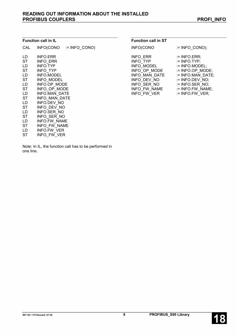
READING OUT INFORMATION ABOUT THE INSTALLEDPROFIBUS COUPLERS PROFI_INFO
907 AC 1131/Issued: 07.02 9 PROFIBUS_S90 Library 18
Function call in ILCAL INFO(CONO := INFO_CONO)
LD INFO.ERRST INFO_ERRLD INFO.TYPST INFO_TYPLD INFO.MODELST INFO_MODELLD INFO.OP_MODEST INFO_OP_MODELD INFO.MAN_DATEST INFO_MAN_DATELD INFO.DEV_NOST INFO_DEV_NOLD INFO.SER_NOST INFO_SER_NOLD INFO.FW_NAMEST INFO_FW_NAMELD INFO.FW_VERST INFO_FW_VER
Note: In IL, the function call has to be performed inone line.
Function call in STINFO(CONO := INFO_CONO);
INFO_ERR := INFO.ERR;INFO_TYP := INFO.TYP;INFO_MODEL := INFO.MODEL;INFO_OP_MODE := INFO.OP_MODE;INFO_MAN_DATE := INFO.MAN_DATE;INFO_DEV_NO := INFO.DEV_NO;INFO_SER_NO := INFO.SER_NO;INFO_FW_NAME := INFO.FW_NAME;INFO_FW_VER := INFO.FW_VER;

POLLING DETAILED DIAGNOSTIC DATAOF A DP SLAVE DPM_SLVDIAG
PROFIBUS_S90 Library 10 907 AC 1131/Issued: 07.0218
POLLING DETAILED DIAGNOSTIC DATAOF A DP SLAVE DPM_SLVDIAGThe block DPM_SLVDIAG reads the detaileddiagnostic data of a DP slave.
Block dataAvailable as of PLC runtime system: V4.0 Remark:Included in library: PROFI40.LIB
PROFIBUS_S90_V41.LIBPROFIBUS_S90_V42.LIBPROFIBUS_Master_S90_V43.LIB CONO, SLV, ERR, MSTR,
EXT_DIAG_DAT - type changed
Block typeFunction block with historical values
ParametersInstance DPM_SLVDIAG Instance nameEN BOOL Enabling the block processingCONO BYTE Slot (module number) of the couplerSLV BYTE Bus address of the specific DP slaveDONE BOOL Ready message of the blockERR WORD Error messageSTAT_1 STATIONSTATUS_1_TYPE Stationstatus_1 according to standardSTAT_2 STATIONSTATUS_2_TYPE Stationstatus_2 according to standardSTAT_3 STATIONSTATUS_3_TYPE Stationstatus_3 according to standardMSTR BYTE Bus address of the related DP masterEXT_DIAG_LEN BYTE Length of the extended diagnostic dataEXT_DIAG_DAT ARRAY [1..238] OF BYTE Extended diagnostic data according to standard
Description
The block DPM_SLVDIAG implements the PROFIBUSfunction Slave_Diag.
Every time a FALSE → TRUE edge is applied to theinput EN, DPM_SLVDIAG reads the data at its inputsand sends a corresponding request message to thecoupler. Further FALSE → TRUE edges at input ENare ignored until the processing of the active request isfinished. The completion of the request processing isindicated by DONE = TRUE.
EN BOOL
If a FALSE → TRUE edge is applied to input EN, allfurther inputs are read in.
If the input values are valid, a corresponding requestmessage is sent to the coupler. While this requestmessage is processed, the output DONE is set toFALSE. If at least one input value is invalid, an error isindicated at output ERR. Additionally the termination ofthe request processing is indicated by DONE = TRUE.
While the request is processed, state changes at inputEN are recognized but not evaluated.

POLLING DETAILED DIAGNOSTIC DATAOF A DP SLAVE DPM_SLVDIAG
907 AC 1131/Issued: 07.02 11 PROFIBUS_S90 Library 18
CONO BYTEAt input CONO the slot (module number) of the coupleris applied which should process the request. Themodule number depends on the PLC category.
R012X CONO = 1R01X2 CONO = 2
Note: Up to version V4.2 (incl.) the data type ofCONO was INT.
SLV BYTEAt input SLV the bus address of the DP slave isapplied, for which diagnostic data are requested.
Note: Up to version V4.2 (incl.) the data type ofSLV was INT.
DONE BOOLThe output DONE reflects the state of the requestprocessing. If the block is trigged by a FALSE → TRUEedge at input EN, DONE is set to FALSE in order toindicate that the request processing is running. Ifprocessing is finished, DONE is set to TRUE.
The values applied at the block outputs are only valid ifDONE = TRUE. Additionally, the diagnostic data areonly valid if ERR = 0. If ERR is not 0, an error occurred.
ERR WORDAt the output ERR an error identifier is applied if aninvalid value was applied to an input or if an erroroccurred during the request processing. ERR hasalways to be considered together with the outputDONE. The value applied at ERR is only valid ifDONE = TRUE. The error message encoding at theoutput ERR applies to all PROFIBUS blocks and isexplained at the beginning of this description.
Note: Up to version V4.2 (incl.) the data type ofERR was INT.
STAT_1 STATIONSTATUS_1_TYPEAt output STAT_1 the first octet of the DP slavediagnostic data is output. STAT_1 is only valid ifDONE = TRUE and ERR = 0.
The structure of the type STATIONSTATUS_1_TYPEcorresponds to the octet Stationstatus_1 defined in thestandard and is described below.
STAT_2 STATIONSTATUS_2_TYPEAt output STAT_2 the second octet of the DP slavediagnostic data is output. STAT_2 is only valid ifDONE = TRUE and ERR = 0.
The structure of the type STATIONSTATUS_2_TYPEcorresponds to the octet Stationstatus_2 defined in thestandard and is described below.
STAT_3 STATIONSTATUS_3_TYPEAt output STAT_3 the third octet of the DP slavediagnostic data is output. STAT_3 is only valid ifDONE = TRUE and ERR = 0.
The structure of the type STATIONSTATUS_3_TYPEcorresponds to the octet Stationstatus_3 defined in thestandard and is described below.
MSTR BYTEAt the output MSTR the bus address of the DP masteris applied, to which the DP slave is assigned. MSTR isonly valid if DONE = TRUE and ERR = 0.
Using the block DPM_SLVDIAG, diagnostic data for allDP slaves can be polled which are connected to thebus. If the diagnostic data are requested by a DP slavewhich was assigned to the PLC during theconfiguration, the PLC bus address is output at MSTR.In multi-master systems it is possible that diagnosticdata are also requested by DP slaves which areassigned to other DP masters. In this case, MSTRoutputs the bus address of the DP master to which therequesting DP slave is assigned.
Note: Up to version V4.2 (incl.) the data type ofMSTR was INT.
EXT_DIAG_LEN BYTEAt the output EXT_DIAG_LEN the number of validbytes, following in EXT_DIAG_DAT are output. IfEXT_DIAG_LEN = 0, no extended diagnostic data areavailable. Otherwise, EXT_DIAG_DAT[1] toEXT_DIAG_DAT[EXT_DIAG_LEN] contain theextended diagnostic data reported by the DP slave.EXT_DIAG_LEN is only valid if DONE = TRUE andERR = 0.
Note: Up to version V4.2 (incl.) the data type ofEXT_DIAG_LEN was INT.

POLLING DETAILED DIAGNOSTIC DATAOF A DP SLAVE DPM_SLVDIAG
PROFIBUS_S90 Library 12 907 AC 1131/Issued: 07.0218
EXT_DIAG_DAT ARRAY [1..238] OF BYTEAt the output EXT_DIAG_DAT the extended diagnosticdata which were reported from the DP slave areapplied as a byte array. The data in EXT_DIAG_DATare only valid if DONE = TRUE, ERR = 0 andEXT_DIAG_LEN > 0.
The extended diagnostic data are structured accordingto the standard. Since the meaning of these data
strongly depends on the used devices, no automaticinterpretation by the block is possible at this point. Theevaluation of the data must be performed by the userwith the aid of the particular device description and theGSD file respectively. The generally applicablestructure of the extended diagnostic data (according tothe standard) is described below.
Function call in ILCAL DIAG
(EN := DIAG_EN,CONO := DIAG_CONO,SLV := DIAG_SLV)
LD DIAG.DONEST DIAG_DONELD DIAG.ERRST DIAG_ERRLD DIAG.STAT_1ST DIAG_STAT_1LD DIAG.STAT_2ST DIAG_STAT_2LD DIAG.STAT_3ST DIAG_STAT_3LD DIAG.MSTRST DIAG_MSTRLD DIAG.EXT_DIAG_LENST DIAG_EXT_DIAG_LENLD DIAG.EXT_DIAG_DATST DIAG_EXT_DIAG_DAT
Note: In IL, the function call has to be performed inone line.
Function call in STDIAG
EN := DIAG_EN,CONO := DIAG_CONO,SLV := DIAG_SLV);
DIAG_DONE := DIAG.DONE;DIAG_ERR := DIAG.ERR;DIAG_STAT_1 := DIAG.STAT_1;DIAG_STAT_2 := DIAG.STAT_2;DIAG_STAT_3 := DIAG.STAT_3;DIAG_MSTR := DIAG.MSTR;DIAG_EXT_DIAG_LEN := DIAG.EXT_DIAG_LEN;DIAG_EXT_DIAG_DAT := DIAG.EXT_DIAG_DAT;
Structure of DP slave diagnostic dataThe block DPM_SLVDIAG divides the diagnostic data of a DP slave into sections and applies them to thecorresponding outputs. The structure of the DP slave diagnostic data is prescribed by the standard as follows:
Octet 1 Stationstatus_1 STAT_1
Octet 2 Stationstatus_2 STAT_2
Octet 3 Stationstatus_3 STAT_3
Octet 4 Master_Add MSTR
Octet 5 to 6 Ident_Number
Octet 7 to 244 Ext_Diag_Data EXT_DIAG_DAT[1] to EXT_DIAG_DAT[EXT_DIAG_LEN]

POLLING DETAILED DIAGNOSTIC DATAOF A DP SLAVE DPM_SLVDIAG
907 AC 1131/Issued: 07.02 13 PROFIBUS_S90 Library 18
Stationstatus_1 STAT_1 STATIONSTATUS_1_TYPE
The diagnostic byte Stationstatus_1 (defined within thestandard) is applied to the output STAT_1 of the blockDPM_SLVDIAG. It is represented as a structure of thedata type STATIONSTATUS_1_TYPE. Within thePROFIBUS master library the structureSTATIONSTATUS_1_TYPE is declared as follows:
TYPE STATIONSTATUS_1_TYPE:STRUCT
NON_EXISTENT: BOOL;NOT_READY: BOOL;CFG_FAULT: BOOL;EXT_DIAG: BOOL;NOT_SUPPORTED: BOOL;INVALID_RESPONSE: BOOL;PRM_FAULT: BOOL;MASTER_LOCK: BOOL;
END_STRUCTEND_TYPE
NON_EXISTENT BOOLIf this bit is set, the PROFIBUS coupler has not found aDP slave at the bus address which was applied at theblock input SLV.
NOT_READY BOOLThis bit is set to TRUE by the DP slave, if the DP slaveis not ready for I/O data exchange.
CFG_FAULT BOOLThis bit is set to TRUE by the DP slave, if theconfiguration data (nominal configuration) receivedfrom the DP master do not match the data stored in theDP slave (actual configuration).
EXT_DIAG BOOLIf this bit is set to TRUE, extended diagnostic data areavailable in EXT_DIAG_DAT. If this bit is not set(FALSE) and EXT_DIAG_LEN > 0, possibly a statusmessage is available in EXT_DIAG_DAT. The meaningof such a status message is device-dependent.
NOT_SUPPORTED BOOLThis bit is set to TRUE by the DP slave, if anunsupported function was requested before.
INVALID_RESPONSE BOOLIf this bit is set to TRUE, the PROFIBUS coupler hasnot received a plausible response from the requestedDP slave.
PRM_FAULT BOOLThe DP slave sets this bit to TRUE, if the parameterdata received last were faulty.
MASTER_LOCK BOOLThis bit is set to TRUE, if the DP slave is assigned toanother DP master. In this case MSTR contains thebus address of this DP master.

POLLING DETAILED DIAGNOSTIC DATAOF A DP SLAVE DPM_SLVDIAG
PROFIBUS_S90 Library 14 907 AC 1131/Issued: 07.0218
Stationstatus_2 STAT_2 STATIONSTATUS_2_TYPE
The diagnostic byte Stationstatus_2 (defined within thestandard) is applied to the output STAT_2 of the blockDPM_SLVDIAG. It is represented as a structure of thedata type STATIONSTATUS_2_TYPE. Within thePROFIBUS master library the structureSTATIONSTATUS_2_TYPE is declared as follows:
TYPE STATIONSTATUS_2_TYPE:STRUCT
PRM_REQ: BOOL;STAT_DIAG: BOOL;DP_Slave: BOOL;WD_ON: BOOL;FREEZE_MODE: BOOL;SYNC_MODE: BOOL;reserved: BOOL;DEACTIVATED: BOOL;
END_STRUCTEND_TYPE
PRM_REQ BOOLThis bit is set to TRUE by the DP slave, if it is requiredto re-parameterize and re-configure the slave (e.g.when adding an additional I/O module). The bit remainsset until the re-parameterization is done.
STAT_DIAG BOOLThis bit is set to TRUE by the DP slave, if the slave hasa static diagnosis. A DP slave with static diagnosis isnot ready for I/O data exchange.
DP slave BOOLThis bit is permanently set to TRUE.
WD_ON BOOLThis bit is set to TRUE by the DP slave, if the slaveresponse monitoring is active.
FREEZE_MODE BOOLThis bit is set to TRUE by the DP slave, if the slave iscurrently running in Freeze mode.
SYNC_MODE BOOLThis bit is set to TRUE by the DP slave, if the slave iscurrently running in Sync mode.
reserved BOOLThis bit is reserved and currently not used.
DEACTIVATED BOOLThis bit is set to TRUE, if the DP slave is not marked asactive in the DP master’s configuration data and hasbeen taken out of the cyclic I/O data exchange (pleaserefer to 907 AC 1131 and 907 FB 1131, 'Slave active incurrent configuration').

POLLING DETAILED DIAGNOSTIC DATAOF A DP SLAVE DPM_SLVDIAG
907 AC 1131/Issued: 07.02 15 PROFIBUS_S90 Library 18
Stationstatus_3 STAT_3 STATIONSTATUS_3_TYPE
The diagnostic byte Stationstatus_3 (defined within thestandard) is applied to the output STAT_3 of the blockDPM_SLVDIAG. It is represented as a structure of thedata type STATIONSTATUS_3_TYPE. Within thePROFIBUS master library the structureSTATIONSTATUS_3_TYPE is declared as follows:
TYPE STATIONSTATUS_3_TYPE:STRUCT
reserved0 : BOOL;reserved1 : BOOL;reserved2 : BOOL;reserved3 : BOOL;reserved4 : BOOL;reserved5 : BOOL;reserved6 : BOOL;EXT_DIAG_OVERFLOW : BOOL;
END_STRUCTEND_TYPE
reserved0 - reserved6 BOOLThese bits are reserved and currently not used.
EXT_DIAG_OVERFLOW BOOLIf this bit is set to TRUE, more diagnostic data areavailable as entered in EXT_DIAG_DAT. For example,the DP slave sets this bit, if currently more diagnosticmessages are queued, than it is able to transfer withinone telegram (see entry Max_Diag_Data_Len in theGSD file).
Master_Add MSTR BYTEInto this octet the DP slave enters the address of the DP master from which it was parameterized (i.e. to which itis assigned). If the DP slave was not yet parameterized by any DP master, the following is valid: MSTR = 255.
Ident_NumberAt this point the DP slave enters its identification number in the diagnosis telegram. The identification number isassigned by the PNO (PROFIBUS Nutzerorganisation e.V. = PROFIBUS user organization) for each devicetype. This number is a firm component of the GSD file. The block DPM_SLVDIAG does not output the deviceidentification number, because the number is not necessary for evaluating the diagnostic data.

POLLING DETAILED DIAGNOSTIC DATAOF A DP SLAVE DPM_SLVDIAG
PROFIBUS_S90 Library 16 907 AC 1131/Issued: 07.0218
Ext_Diag_Data EXT_DIAG_DAT ARRAY [1..238] OF BYTEThe above described six bytes of standard diagnosticdata have to be supported by each DP slave.Optionally, a DP slave can additionally provideextended diagnostic data. This is the case if a valuegreater than 6 is assigned to the itemMax_Diag_Data_Len in the GSD file of the DP slave.The format of the extended diagnosis is determined inthe standard. Since the extended diagnostic data arenot static on the one side and can containmanufacturer-specific entries on the other side, noautomatic data evaluation can be performed by theblock DM_SLVDIAG.
The evaluation of extended diagnostic data must beperformed by the user with the aid of the GSD file forthe particular DP slave and the description of thegenerally applicable data format given below.
The extended diagnostic data are divided into threeranges:
- device-related diagnosis
- module-related diagnosis
- channel-related diagnosis
Device-related diagnosisThe device-related diagnosis contains generaldiagnostic information, such as overtemperature orundervoltage. This range is initiated by a header byte,in which the highest two bits are permanently set to 00.The lower six bits indicate the length of the followingblock, including the header byte itself.
0 0 L e n g t h7 6 5 4 3 2 1 0
The device-related diagnostic data are defined by themanufacturer. For detailed information about theirmeaning please refer to the particular devicedocumentation.
Module-related diagnosisThe module-related diagnosis contains diagnosticinformation which can be assigned directly to theparticular I/O modules of the device. The rangecontaining the module-related diagnosis starts with aheader byte, in which the highest two bits arepermanently set to 01. The lower six bits indicate thelength of the following block, including the header byteitself.
0 1 L e n g t h7 6 5 4 3 2 1 0
In the following block one single bit is assigned to eachmodule. The module index is represented by the bitoffset within the block (please refer to the example). If abit is set to TRUE, this means that a diagnosis has tobe done in the related I/O module.
Channel-related diagnosisIn the channel-related diagnosis range, the diagnosedchannels and the cause for the diagnosis are enteredone after the other. Each entry consists of three bytesand starts with a header byte, in which the highest twobits are permanently set to 10. The lower six bitscontain the index of the module, for which the followingdiagnosis is performed.
1 0 M o d u l e7 6 5 4 3 2 1 0
The lower six bits of the following byte contain thenumber of the channel which reports a diagnosis. Thehighest two bits indicate whether the specific channel isan input channel, an output channel or an I/O channel.
I/O Channel7 6 5 4 3 2 1 0
The direction identifier in the bits 6 and 7 is encoded asfollows:
0 0 Reserved0 1 Input1 0 Output1 1 Input/output
The third byte of each entry contains the channel typein its upper three bits and the error type in the lowerfive bits.
Channel type Error type7 6 5 4 3 2 1 0
The channel type (channel width) is encoded asfollows:
0 0 0 Reserved0 0 1 Bit0 1 0 2 bits0 1 1 4 bits1 0 0 Byte1 0 1 Word1 1 0 2 words1 1 1 Reserved
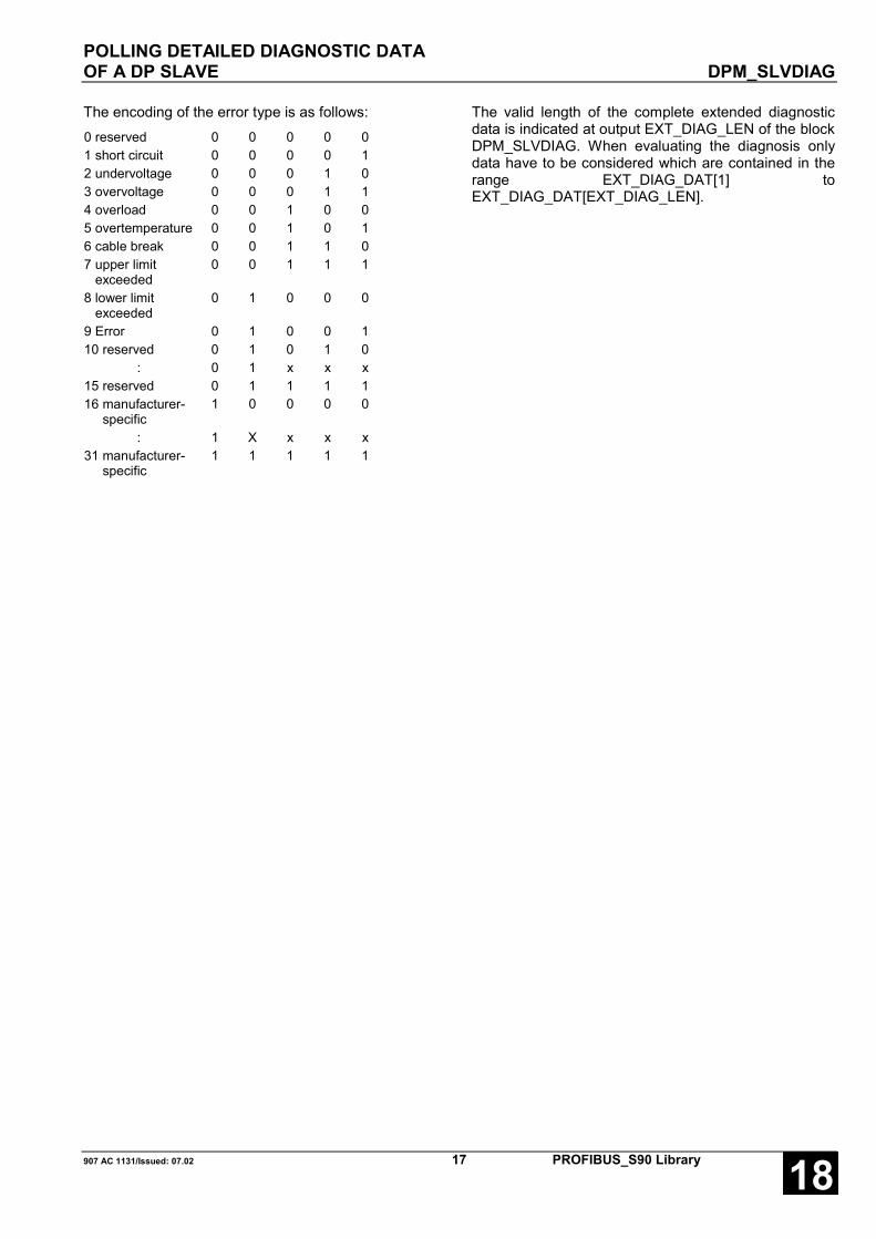
POLLING DETAILED DIAGNOSTIC DATAOF A DP SLAVE DPM_SLVDIAG
907 AC 1131/Issued: 07.02 17 PROFIBUS_S90 Library 18
The encoding of the error type is as follows:0 reserved 0 0 0 0 01 short circuit 0 0 0 0 12 undervoltage 0 0 0 1 03 overvoltage 0 0 0 1 14 overload 0 0 1 0 05 overtemperature 0 0 1 0 16 cable break 0 0 1 1 07 upper limit exceeded
0 0 1 1 1
8 lower limit exceeded
0 1 0 0 0
9 Error 0 1 0 0 110 reserved 0 1 0 1 0
: 0 1 x x x15 reserved 0 1 1 1 116 manufacturer- specific
1 0 0 0 0
: 1 X x x x31 manufacturer- specific
1 1 1 1 1
The valid length of the complete extended diagnosticdata is indicated at output EXT_DIAG_LEN of the blockDPM_SLVDIAG. When evaluating the diagnosis onlydata have to be considered which are contained in therange EXT_DIAG_DAT[1] toEXT_DIAG_DAT[EXT_DIAG_LEN].

POLLING DETAILED DIAGNOSTIC DATAOF A DP SLAVE DPM_SLVDIAG
PROFIBUS_S90 Library 18 907 AC 1131/Issued: 07.0218
Example for extended diagnostic dataEXT_DIAG_LEN = 15
7 6 5 4 3 2 1 0 EXT_DIAG_DAT[1] 0 0 0 0 0 1 0 0 Device-related diagnosis
Length: 4 bytes incl. header byte EXT_DIAG_DAT[2] X x x X X x X X Device-related diagnosis EXT_DIAG_DAT[3] X x x X X x X X Length: 3 bytes
EXT_DIAG_DAT[4] X x x X X x X X Meaning of the data is manufacturer- specific
EXT_DIAG_DAT[5] 0 1 0 0 0 1 0 1 ID-related diagnosis Length: 5 bytes incl. header byte
EXT_DIAG_DAT[6] 0 7 0 6 0 5 0 4 0 3 0 2 0 1 1 0 Module 0 with diagnosis EXT_DIAG_DAT[7] 015 014 013 112 011 010 0 9 0 8 Module 12 with diagnosis EXT_DIAG_DAT[8] 023 022 021 020 019 118 017 016 Module 18 with diagnosis EXT_DIAG_DAT[9] 031 130 029 028 027 026 025 024 Module 30 with diagnosis EXT_DIAG_DAT[10] 1 0 0 0 0 0 0 0 Channel-related diagnosis
Module 0 EXT_DIAG_DAT[11] 0 1 0 0 0 0 1 0 Channel 2, Input EXT_DIAG_DAT[12] 0 0 1 0 0 1 0 0 Overload, channel organized bit-wise EXT_DIAG_DAT[13] 1 0 0 0 1 1 0 0 Channel-related diagnosis
Module 12 EXT_DIAG_DAT[14] 1 0 0 0 0 1 1 0 Channel 6, output EXT_DIAG_DAT[15] 1 0 1 0 0 1 1 1 Upper limit exceeded,
channel organized word-wise
Example program for evaluating extended diagnostic dataA detailed example program for the evaluation of extended diagnostic data can be found on the CD-ROM for907 AC 1131 and in the programming system online help.

READING OUT THE PROFIBUS COUPLER STATUS DPM_STAT
907 AC 1131/Issued: 07.02 19 PROFIBUS_S90 Library 18
READING OUT THE PROFIBUS COUPLER STATUS DPM_STATDPM_STAT outputs the status of a PROFIBUS couplerin operation mode DP master. At the outputs,information about the communication state and theerror events are output.
Block dataAvailable as of PLC runtime system: V4.0 Remark:Included in library: PROFI40.LIB
PROFIBUS_S90_V41.LIBPROFIBUS_S90_V42.LIBPROFIBUS_Master_S90_V43.LIB CONO, ERR, DPM_STATE,
COM_ERR, BUS_ERR,TIME_OUT - type changed
Block typeFunction block without historical values
ParametersInstance DPM_STAT Instance nameEN BOOL Enabling the block processingCONO BYTE Slot (module number) of the couplerERR WORD Error messageSTAT_BITS DPM_STATE_BITS_TYPE Atypical communication statesDPM_STATE WORD DP master state according to standardCOM_ERR DPM_COM_ERR_TYPE Communication errorBUS_ERR WORD Number of serious bus errorsTIME_OUT WORD Number of timeouts
DescriptionThe block DPM_STAT outputs the current state of aPROFIBUS coupler in operation mode DP master.DPM_STAT is active if input EN = TRUE. If the block isactive, the current values are always displayed at theoutputs.
EN BOOLThe block can be activated (EN = TRUE) or deactivated(EN = FALSE) via the input EN. If the block is active,the current values are available at the outputs.
CONO BYTEAt input CONO the slot (module number) of the coupleris applied, for which the state should be read. Themodule number depends on the PLC category.
R012X CONO = 1R01X2 CONO = 2
Note: Up to version V4.2 (incl.) the data type ofCONO was INT.
ERR WORDAn error identification is output at output ERR, if aninvalid value is applied at a block input. ERR hasalways to be considered together with the input EN.The value applied at ERR is only valid if EN = TRUE.All further outputs are only valid if EN = TRUE andERR = 0. The error messages encoding at the outputERR applies to all PROFIBUS blocks and is explainedat the beginning of this description.
Note: Up to version V4.2 (incl.) the data type ofERR was INT.

READING OUT THE PROFIBUS COUPLER STATUS DPM_STAT
PROFIBUS_S90 Library 20 907 AC 1131/Issued: 07.0218
STATE_BITS DPM_STATE_BITS_TYPEAt output STATE_BITS atypical communication statesat the PROFIBUS are displayed. STAT_BITS is onlyvalid if EN = TRUE and ERR = 0.
The structure of the type DPM_STATE_BITS_TYPE isdefined in the PROFIBUS master library and isdescribed below.
DPM_STATE BYTEAt output DPM_STATE, the DP master state is outputaccording to the standard. The following states aredefined:
OFFLINE 00HEX / 00DEC
STOP 40HEX / 64DEC
CLEAR 80HEX / 128DEC
OPERATE C0HEX / 192DEC
DPM_STATE = OFFLINE
The PROFIBUS coupler is in the initialization state ifDPM_STATE has the value OFFLINE. After theinitialization phase is completed the coupler changes toSTOP state.
DPM_STATE = STOP
The coupler is completely initialized, if DPM_STATEhas the value STOP. In this state the coupler is readyto receive configuration data. No data exchange withthe DP slaves is performed. The coupler has this stateif no user program is running.
DPM_STATE = CLEAR
If the user program is started, the coupler changes fromSTOP state into CLEAR state and begins, via the bus,to parameterize (set into operation) the DP slaveswhich were assigned during the configuration. After thesetup has been completed successfully, the couplerchanges into OPERATE state. If an error occurs duringthe parameter setting, the coupler changes back toSTOP state.
DPM_STATE = OPERATE
Normally the coupler is in OPERATE state while a userprogram is running. In this state the DP masterexchanges I/O data with the DP slaves. If an erroroccurs during this process and ‘Auto Clear Mode’ wasselected during the configuration, the coupler changesback to CLEAR state and tries again to parameterizethe DP slaves. If ‘Auto Clear Mode’ was not selected,the coupler remains (in case of an error) in OPERATEstate. If the user program is stopped, the coupler alsochanges back to STOP state.
DPM_STATE is only valid if EN = TRUE and ERR = 0.
Note: Up to version V4.2 (incl.) the data type ofDPM_STATE was INT.
COM_ERR DPM_COM_ERR_TYPEAt output COM_ERR possible communication errorsare displayed. COM_ERR is only valid if EN = TRUEand ERR = 0.
The structure of the type DPM_COM_ERR_TYPE isdefined in the PROFIBUS master library and isdescribed below together with the possible errors.
Note: Up to version V4.2 (incl.) the data type ofCOM_ERR was COM_ERR_TYPE.
BUS_ERR WORDAt output BUS_ERR the number of serious bus errors,e.g. short circuits on the transmission line whichoccurred since the system start are output. BUS_ERRis only valid if EN = TRUE and ERR = 0.
Note: Up to version V4.2 (incl.) the data type ofBUS_ERR was INT.
TIME_OUT WORDAt output TIME_OUT the number of timeout errorswhich occurred since the system start are output. Atimeout error occurs, if a DP slave does not responseto a DP master request within the configured time.TIME_OUT is only valid if EN = TRUE and ERR = 0.
Note: Up to version V4.2 (incl.) the data type ofTIME_OUT was INT.

READING OUT THE PROFIBUS COUPLER STATUS DPM_STAT
907 AC 1131/Issued: 07.02 21 PROFIBUS_S90 Library 18
Function call in ILCAL STAT(EN := STAT_EN,CONO := STAT_CONO)
LD STAT.ERRST STAT_ERRLD STAT.STATE_BITSST STAT_STATE_BITSLD STAT.DPM_STATEST STAT_DPM_STATELD STAT.COM_ERRST STAT_COM_ERRLD STAT.BUS_ERRST STAT_BUS_ERRLD STAT.TIME_OUTST STAT_TIME_OUT
Note: In IL, the function call has to be performed inone line.
Function call in STSTAT
(EN := STAT_EN,CONO := STAT_CONO);
STAT_ERR := STAT.ERR;STAT_STATE_BITS := STAT.STATE_BITS;STAT_DPM_STATE := STAT.DPM_STATE;STAT_COM_ERR := STAT.COM_ERR;STAT_BUS_ERR := STAT.BUS_ERR;STAT_TIME_OUT := STAT.TIME_OUT;

READING OUT THE PROFIBUS COUPLER STATUS DPM_STAT
PROFIBUS_S90 Library 22 907 AC 1131/Issued: 07.0218
STATE_BITS DPM_STATE_BITS_TYPEThe structure STATE_BITS includes four booleanvariables which display different communication states.Within the PROFIBUS master library the data typeDPM_STATE_BITS_TYPE is declared as follows:
TYPE DPM_STATE_BITS_TYPE:STRUCT
CTRL: BOOL;AUTO_CLR: BOOL;NO_EXCH: BOOL;FATAL: BOOL;
END_STRUCTEND_TYPE
CTRL BOOLIf this bit is set to TRUE, a parameter setting erroroccurred. In normal operation CTRL should be FALSE.If not, the parameter and configuration data have to bechecked.
AUTO_CLR BOOLThis bit is only valid if ‘Auto Clear Mode’ was selectedduring the configuration. If AUTO_CLR is set to TRUE,an error occurred during the communication with atleast one DP slave. As a result, the coupler stopped thedata exchange with all DP slaves and changed back toCLEAR state (see DPM_STATE).
NO_EXCH BOOLThis bit is set to TRUE, if the process data exchangewith one or several DP slaves is not possible. The errorcause can be found in the configuration data as well asin the DP slaves themselves.
FATAL BOOLIf FATAL is set to TRUE, no communication via thePROFIBUS is possible due to a serious bus error (e.g.bus line short circuit). In this case, all bus lines have tobe checked.

READING OUT THE PROFIBUS COUPLER STATUS DPM_STAT
907 AC 1131/Issued: 07.02 23 PROFIBUS_S90 Library 18
COM_ERR DPM_COM_ERR_TYPECommunication errors can be located precisely viaCOM_ERR. The output COM_ERR is represented as astructure of the type DPM_COM_ERR_TYPE. Withinthe PROFIBUS master library this data type is declaredas follows:
TYPE DPM_COM_ERR_TYPE:STRUCT
ADDRESS: BYTE;EVENT: BYTE;
END_STRUCTEND_TYPE
ADDRESS BYTEIn case of an error, ADDRESS contains the busaddress of the faulty subscriber (0 to 255). IfADDRESS has the value 255, the error is located in thecoupler itself.
EVENT BYTEEVENT displays the cause of an error. The followingtables show the encoding of the various errors.
ADDRESS = 255 Coupler error
EVENT Meaning Error source Remedy 50 USR_INTF task not found Coupler Contact ABB 51 No global data field Coupler Contact ABB 52 FDL task not found Coupler Contact ABB 53 PLC task not found Coupler Contact ABB
54 No master parameter record Configuration Generate configuration in the project andreload program to controller
55 Faulty value in master parameterrecord Configuration Check configuration data for coupler in the
project and/or reload program to controller
56 No slave parameter records Configuration Add DP slaves to configuration data andreload program to controller
57 Faulty value in a slave parameterrecord Configuration
Check configuration data of subordinate DPslaves in the project and/or reload program tocontroller
58 Doubled slave address ConfigurationCheck configuration data of subordinate DPslaves in the project for doubled busaddresses and/or reload program to controller
59 Invalid offset address output data ConfigurationCheck configuration data of subordinate DPslaves in the project for invalid IEC addressesand/or reload program to controller
60 Invalid offset address input data ConfigurationCheck configuration data of subordinate DPslaves in the project for invalid IEC addressesand/or reload program to controller
61 Range overlapping in output data Configuration
Check configuration data of subordinate DPslaves in the project for overlapping IECaddress ranges and/or reload program tocontroller
62 Range overlapping in input data Configuration
Check configuration data of subordinate DPslaves in the project for overlapping IECaddress ranges and/or reload program tocontroller
63 Unknown process data handshake Controlsystem
Supply voltage OFF/ON, otherwise contactABB
64 Insufficient memory Coupler Contact ABB
65 Faulty slave parameter record ConfigurationCheck configuration data of subordinate DPslaves in the project and/or reload program tocontroller
202 No segment available Coupler Contact ABB
212 Error reading database Configuration/ Coupler
Reload program with configuration data tocontroller
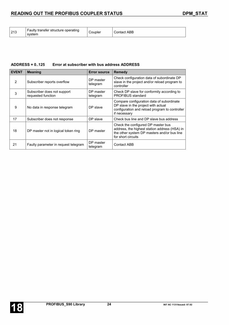
READING OUT THE PROFIBUS COUPLER STATUS DPM_STAT
PROFIBUS_S90 Library 24 907 AC 1131/Issued: 07.0218
213 Faulty transfer structure operatingsystem Coupler Contact ABB
ADDRESS = 0..125 Error at subscriber with bus address ADDRESS
EVENT Meaning Error source Remedy
2 Subscriber reports overflow DP mastertelegram
Check configuration data of subordinate DPslave in the project and/or reload program tocontroller
3 Subscriber does not supportrequested function
DP mastertelegram
Check DP slave for conformity according toPROFIBUS standard
9 No data in response telegram DP slave
Compare configuration data of subordinateDP slave in the project with actualconfiguration and reload program to controllerif necessary
17 Subscriber does not response DP slave Check bus line and DP slave bus address
18 DP master not in logical token ring DP master
Check the configured DP master busaddress, the highest station address (HSA) inthe other system DP masters and/or bus linefor short circuits
21 Faulty parameter in request telegram DP mastertelegram Contact ABB
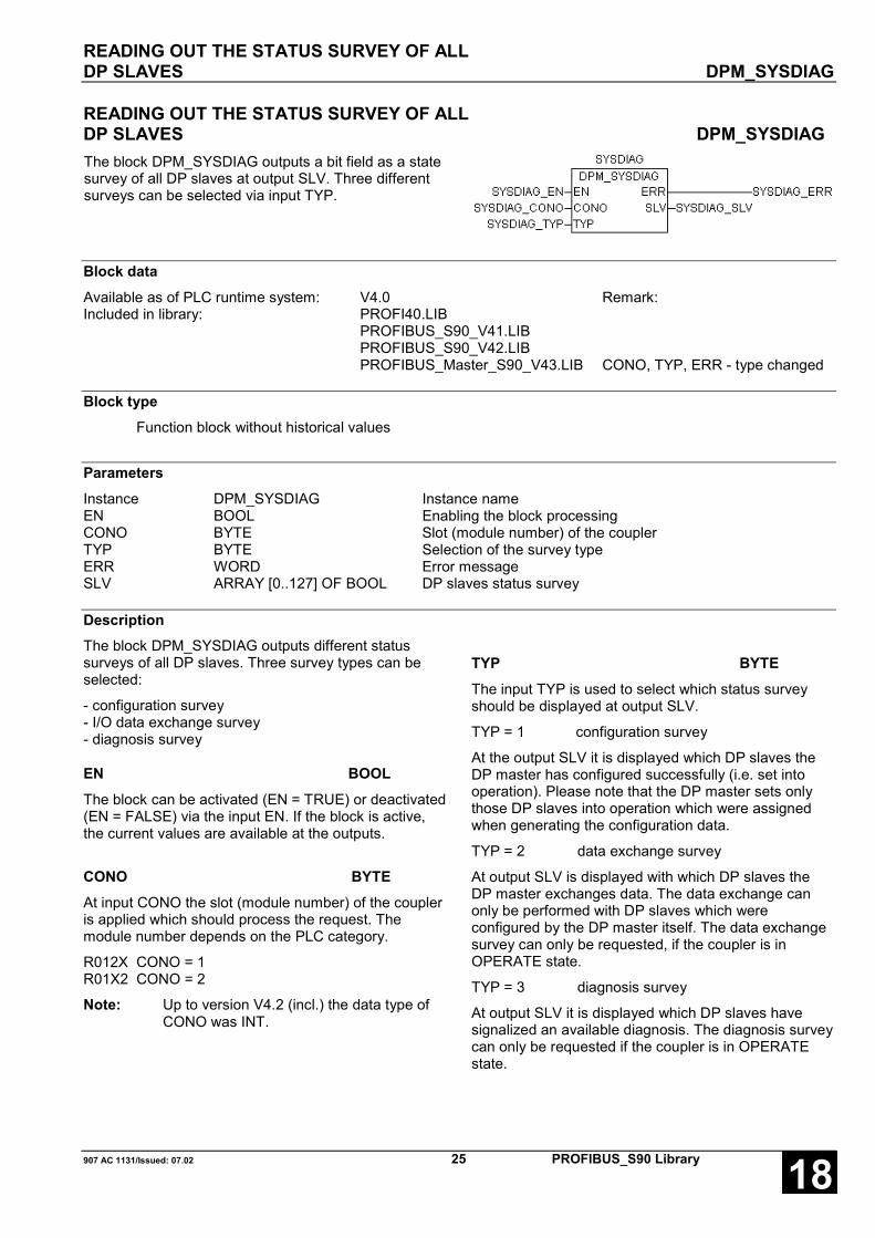
READING OUT THE STATUS SURVEY OF ALLDP SLAVES DPM_SYSDIAG
907 AC 1131/Issued: 07.02 25 PROFIBUS_S90 Library 18
READING OUT THE STATUS SURVEY OF ALLDP SLAVES DPM_SYSDIAGThe block DPM_SYSDIAG outputs a bit field as a statesurvey of all DP slaves at output SLV. Three differentsurveys can be selected via input TYP.
Block dataAvailable as of PLC runtime system: V4.0 Remark:Included in library: PROFI40.LIB
PROFIBUS_S90_V41.LIBPROFIBUS_S90_V42.LIBPROFIBUS_Master_S90_V43.LIB CONO, TYP, ERR - type changed
Block typeFunction block without historical values
ParametersInstance DPM_SYSDIAG Instance nameEN BOOL Enabling the block processingCONO BYTE Slot (module number) of the couplerTYP BYTE Selection of the survey typeERR WORD Error messageSLV ARRAY [0..127] OF BOOL DP slaves status survey
DescriptionThe block DPM_SYSDIAG outputs different statussurveys of all DP slaves. Three survey types can beselected:
- configuration survey- I/O data exchange survey- diagnosis survey
EN BOOLThe block can be activated (EN = TRUE) or deactivated(EN = FALSE) via the input EN. If the block is active,the current values are available at the outputs.
CONO BYTEAt input CONO the slot (module number) of the coupleris applied which should process the request. Themodule number depends on the PLC category.
R012X CONO = 1R01X2 CONO = 2
Note: Up to version V4.2 (incl.) the data type ofCONO was INT.
TYP BYTEThe input TYP is used to select which status surveyshould be displayed at output SLV.
TYP = 1 configuration survey
At the output SLV it is displayed which DP slaves theDP master has configured successfully (i.e. set intooperation). Please note that the DP master sets onlythose DP slaves into operation which were assignedwhen generating the configuration data.
TYP = 2 data exchange survey
At output SLV is displayed with which DP slaves theDP master exchanges data. The data exchange canonly be performed with DP slaves which wereconfigured by the DP master itself. The data exchangesurvey can only be requested, if the coupler is inOPERATE state.
TYP = 3 diagnosis survey
At output SLV it is displayed which DP slaves havesignalized an available diagnosis. The diagnosis surveycan only be requested if the coupler is in OPERATEstate.
READING OUT THE STATUS SURVEY OF ALLDP SLAVES DPM_SYSDIAG
PROFIBUS_S90 Library 26 907 AC 1131/Issued: 07.0218
Note: Up to version V4.2 (incl.) the data type ofTYP was INT.
ERR WORDAn error identification is applied at the output ERR if aninvalid value is applied at an input. ERR has always tobe considered together with the input EN. The valueapplied at ERR is only valid if EN = TRUE. All furtheroutputs are only valid if EN = TRUE and ERR = 0. Theerror messages encoding at the output ERR applies toall PROFIBUS blocks and is explained at the beginningof this description.
Note: Up to version V4.2 (incl.) the data type ofERR was INT.
SLV ARRAY [0..127] OF BOOLAt output SLV, the status survey is output as a bit field.Every bit within this field represents a DP slave. Withthis, the index corresponds to the DP slave busaddress. A bit which is set to TRUE means that thestate selected via TYP is applicable for thecorresponding DP slave.
If e.g. TYP = 1 is selected and SLV[2] = TRUE, the DPslave was successfully configured with bus address 2by the DP master. If SLV[2] = FALSE, the configurationof the specific DP slave has not yet been completed orthe DP slave is not part of the DP master configurationdata.
If TYP = 2 was selected and SLV[2] = TRUE, thismeans that the DP master exchanges I/O data with theDP slave which has bus address 2. However, ifSLV[2] = FALSE, the DP master currently does notexchange I/O data with the DP slave. The DP master isonly able to exchange data with those DP slaves whichit has successfully set into operation before.
For TYP = 3 e.g. SLV[2] = TRUE means that the DPslave with bus address 2 has signalized a diagnosis.The detailed diagnosis can be requested by using theblock DPM_SLVDIAG.
The bit field output at SLV is only valid if EN = TRUEand ERR = 0.
Function call in ILCAL SYSDIAG
(EN := SYSDIAG_EN,CONO := SYSDIAG_CONO,TYP := SYSDIAG_TYP)
LD SYSDIAG.ERRST SYSDIAG_ERRLD SYSDIAG.SLVST SYSDIAG_SLV
Note: In IL, the function call has to be performed inone line.
Function call in STSYSDIAG
(EN := SYSDIAG_EN,CONO := SYSDIAG_CONO,TYP := SYSDIAG_TYP);
SYSDIAG_ERR := SYSDIAG.ERR;SYSDIAG_SLV := SYSDIAG.SLV;

SENDING GLOBAL CONTROL COMMANDSTO THE DP SLAVE DPM_CTRL
907 AC 1131/Issued: 07.02 27 PROFIBUS_S90 Library 18
SENDING GLOBAL CONTROL COMMANDSTO THE DP SLAVE DPM_CTRLThe block DPM_CTRL sends GlobalControl commands for the timesynchronization of process data ofseveral DP slaves.
Block dataAvailable as of PLC runtime system: V4.0 Remark:Included in library: PROFIBUS_Master_S90_V43.LIB
Block typeFunction block with historical values
ParametersInstance DPM_CTRL Instance nameEN BOOL Enabling the block processingCONO BYTE Slot (module number) of the couplerSLV BYTE Selection of the called DP slavesGROUP_SEL BYTE Selection of the called slave groupsCLR_DATA BOOL Resetting the output data of the DP slavesUNFREEZE BOOL Termination of the input data synchronizationFREEZE BOOL Synchronization of the input dataUNSYNC BOOL Termination of the output data synchronizationSYNC BOOL Synchronization of the output dataDONE BOOL Ready message of the blockERR WORD Error message
DescriptionThe block DPM_CTRL implements the PROFIBUSfunction Global_Control. Global_Control is a broadcastfunction.
Using Global Control commands the output data ofone, several or all slaves can be reset or the input oroutput data of the slaves can be synchronized. Thecommands are selected via combinations of theoutputs CLR_DATA, FREEZE / UNFREEZE and SYNC/ UNSYNC. The called slaves are selected using threeparameters. First, during the project planning, theslaves can be divided into logical groups (refer toAC1131 Configurator and FB1131 documentation).Then the slaves can be specifically called individuallyor in groups via the block inputs SLV and GROUP_SLVduring running operation. Every time a FALSE → TRUEedge is applied to input EN, DPM_CTRL reads the dataat its inputs and sends a corresponding requestmessage to the coupler. Further FALSE → TRUE
edges at input EN are ignored until processing of theactive request is finished. The completion of therequest processing is indicated by DONE = TRUE.
EN BOOL
If a FALSE → TRUE edge is applied to input EN, allfurther inputs are read in.
If the input values are valid, a corresponding requestmessage is sent to the coupler. While this requestmessage is processed, the output DONE is set toFALSE. If at least one input value is invalid, an error isindicated at output ERR. Additionally the termination ofthe request processing is indicated by DONE = TRUE.While the request is processed, state changes at inputEN are recognized but not evaluated.

SENDING GLOBAL CONTROL COMMANDSTO THE DP SLAVE DPM_CTRL
PROFIBUS_S90 Library 28 907 AC 1131/Issued: 07.0218
CONO BYTEAt input CONO the slot (module number) of the coupleris applied which should process the request. Themodule number depends on the PLC category.
R012X CONO = 1R01X2 CONO = 2
SLV BYTEAt input SLV the bus address of the DP slave isapplied, to which a Global Control command shall besent. With SLV = 0..126, an individual slave with thecorresponding bus address is directly called,independent of the group it was assigned duringconfiguration and independent of the value applied atblock input GROUP_SEL. If SLV = 127 andGROUP_SEL = 0, all slaves are called simultaneously.The selection of individual slave groups is done withSLV = 127 and a combination of GROUP_SEL and thegroup assignment during configuration. This is why theblock outputs SLV and GROUP_SEL always have tobe considered together with the group assignmentperformed during configuration. The possiblecombinations are explained following the description ofthe block inputs.
GROUP_SEL BYTEAt input GROUP_SEL the slave groups are selected, towhich a Global Control command shall be sent. WithSLV = 0..126, an individual slave with thecorresponding bus address is directly called,independent of the group assignment duringconfiguration and independent of the value applied atblock input GROUP_SEL. If GROUP_SEL = 0 and SLV= 127, all slaves are called simultaneously. Theselection of individual slave groups is done with SLV =127 and a combination of GROUP_SEL and the groupassignment during configuration. This is why the blockoutputs SLV and GROUP_SEL always have to beconsidered together with the group assignmentperformed during configuration. The possiblecombinations are explained following the description ofthe block inputs.
CLR_DATA BOOLWith the input CLR_DATA the output data of the on-siteslaves can be reset. The called slave resets its outputson-site to 0 when it receives a Global Control commandwith CLR_DATA = TRUE. If the CLR_DATA part of acommand is FALSE, the outputs of the called slaveskeep their present state. Slaves which are not calledignore the whole command. The possible combinationsof individual commands are explained following thedescription of the block inputs.
UNFREEZE BOOLWhen input UNFREEZE is TRUE the synchronizationmode for the input data of the called slaves isterminated, regardless whether the input FREEZE isTRUE or FALSE at this moment. From now on, thecalled slaves forward their input values immediately tothe master again. If the UNFREEZE part of a commandis FALSE, the called slaves keep their present state.The UNFREEZE command is ignored if the called slaveis not in the FREEZE state. Slaves which are not calledignore the whole command. UNFREEZE has always tobe considered together with FREEZE. The possiblecombinations of individual commands are explainedfollowing the description of the block inputs.
FREEZE BOOLWhen input FREEZE is TRUE and at the same timeinput UNFREEZE is FALSE, the called slaves areoperated in the input data synchronization mode. Thismode is activated with the first FREEZE command. Asa result, the called slaves simultaneously freeze thepresent values applied at their local inputs andtemporarily store them. During the subsequent processdata cycles the temporarily stored input values aretransmitted to the master, regardless whether theactual input values have changed in the mean time ornot. When another FREEZE command is received, thetemporarily stored input values are updated, i.e. thecalled slaves again simultaneously store the presentinput values into an internal buffer and then transmitthese values to the master during the subsequentcycles. FREEZE has always to be considered togetherwith UNFREEZE. The possible combinations ofindividual commands are explained following thedescription of the block inputs.
UNSYNC BOOLWhen input UNSYNC is TRUE the synchronizationmode for the output data of the called slaves isterminated, regardless whether the input SYNC isTRUE or FALSE at this moment. From now on, thecalled slaves forward the output data received from themaster immediately to their own outputs again. If theUNSYNC part of a command is FALSE, the calledslaves keep their present state. The UNSYNCcommand is ignored if the called slave is not in theSYNC state. Slaves which are not called ignore thewhole command. UNSYNC has always to beconsidered together with SYNC. The possiblecombinations of individual commands are explainedfollowing the description of the block inputs.

SENDING GLOBAL CONTROL COMMANDSTO THE DP SLAVE DPM_CTRL
907 AC 1131/Issued: 07.02 29 PROFIBUS_S90 Library 18
SYNC BOOLWhen input SYNC is TRUE and at the same time inputUNSYNC is FALSE, the called slaves are operated inthe output data synchronization mode. This mode isactivated with the first SYNC command. As a result, thecalled slaves freeze the present states of their localoutputs. The output data sent during the subsequentprocess data cycles are first only locally stored in theseslaves. Then, when another SYNC command isreceived, the slaves simultaneously apply thesetemporarily stored values to their outputs. SYNC hasalways to be considered together with UNSYNC. Thepossible combinations of individual commands areexplained following the description of the block inputs.
DONE BOOLThe output DONE reflects the state of the requestprocessing. If the block is trigged by a FALSE → TRUE
edge at input EN, DONE is set to FALSE in order toindicate that the request processing is running. Ifprocessing is finished, DONE is set to TRUE.
The values applied at the block outputs are only valid ifDONE = TRUE. The Global Control command was onlyexecuted correctly if also ERR = 0. If ERR is not 0, anerror occurred.
ERR WORDAt the output ERR an error identifier is applied if aninvalid value was applied to an input or if an erroroccurred during the request processing. ERR hasalways to be considered together with the outputDONE. The value applied at ERR is only valid ifDONE = TRUE. The error message encoding at theoutput ERR applies to all PROFIBUS blocks and isexplained following the block descriptions.
Function call in ILCAL CTRL
(EN := CTRL_EN,CONO := CTRL_CONO,SLV := CTRL_SLVGROUP_SEL :=CTRL_GROUP_SELCLR_DATA := TRL_CLR_DATA,UNFREEZE := CTRL_UNFREEZE,FREEZE := CTRL_FREEZE,UNSYNC := CTRL_UNSYNC,SYNC := CTRL_SYNC)
LD CTRL.DONEST CTRL_DONELD CTRL.ERRST CTRL_ERR
Note: In IL, the function call has to be performed inone line.
Function call in STCTRL
(EN := CTRL_EN,CONO := CTRL_CONO,SLV := CTRL_SLV,GROUP_SEL := CTRL_GROUP_SEL,CLR_DATA := CTRL_CLR_DATA,UNFREEZE := CTRL_UNFREEZE,FREEZE := CTRL_FREEZE,UNSYNC := CTRL_UNSYNC,SYNC := CTRL_SYNC);
CTRL_DONE := CTRL.DONE;CTRL_ERR := CTRL.ERR;

SENDING GLOBAL CONTROL COMMANDSTO THE DP SLAVE DPM_CTRL
PROFIBUS_S90 Library 30 907 AC 1131/Issued: 07.0218
Selection of the called slavesDuring offline configuration of the master using 907 AC 1131 or 907 FB 1131 the master is first informed with whichslaves it should exchange process data. Here, the inserted slaves are not yet assigned to a particular group andcan only be called individually via their bus address. In a further step the slaves can be combined to logical groups(refer to AC1131 and FB1131 documentation). For this purpose, first the global properties of each single groupmust be determined. Each group can have only SYNC properties, only FREEZE properties or both properties. Upto eight groups can be defined. Then, as part of the slave configuration or of the slave properties, it must bedetermined to which group or groups the individual slave is to be assigned. The group assignment itself does notinfluence the cyclic exchange of process data. It becomes only effective in conjunction with Global Controlcommands.
During the boot process of the bus and the parameter assignment of the slaves performed by the master, eachsingle slave is informed about its group assignment. This information is combined in one byte with each single bitrepresenting one of the eight possible groups.
G 8 G 7 G 6 G 5 G 4 G 3 G 2 G 17 6 5 4 3 2 1 0
For instance, if a slave shall be assigned to the groups 7 and 1, the master sends a byte with the decimal value 65= binary value 01000001 to this slave.
The selection which slaves shall be called by a Global Control command during the running operation is done bythe block inputs SLV and GROUP_SEL. With SLV = 0..126 only the slave with a bus address = SLV is called,independent of the group assignment and of the value applied at input GROUP_SEL. All other slaves discard thistelegram. With SLV = 127 and GROUP_SEL = 0 all slaves on the bus are called, independent of their groupassignment. The group assignment performed during the configuration is only considered by the slaves if theyreceive a Global Control command with SLV = 127 and GROUP_SEL unequal to 0. In this case, the slavecompares the GROUP_SEL value with the group assignment byte received during the parameter assignment. Theslave accepts the command if a bit-wise collation of the two values delivers a value unequal to 0 and discards thecommand if the collation delivers a value of 0. For instance, if a slave which is assigned to groups 1 and 7 (seeabove) receives a Global Control command with SLV = 127 and GROUP_SEL = 64 dec. (= 01000000 bin.), thecommand is also (among others) addressed to this slave.
Group assignment 0 1 0 0 0 0 0 1
GROUP_SEL AND 0 1 0 0 0 0 0 0
Result 0 1 0 0 0 0 0 0
The following table provides an overview of possible combinations of the three parameters group assignment, SLVand GROUP_SEL and the slaves called with these combinations.
SLV GROUP_SEL Group assignment Called slaves
0 - 126 X X Only slave with bus address = SLV
127 0 X All slaves
127 1 - 255 1 - 255 Slaves for which the bit-wise collation of group assignment and GROUP_SEL delivers a value unequal to 0.
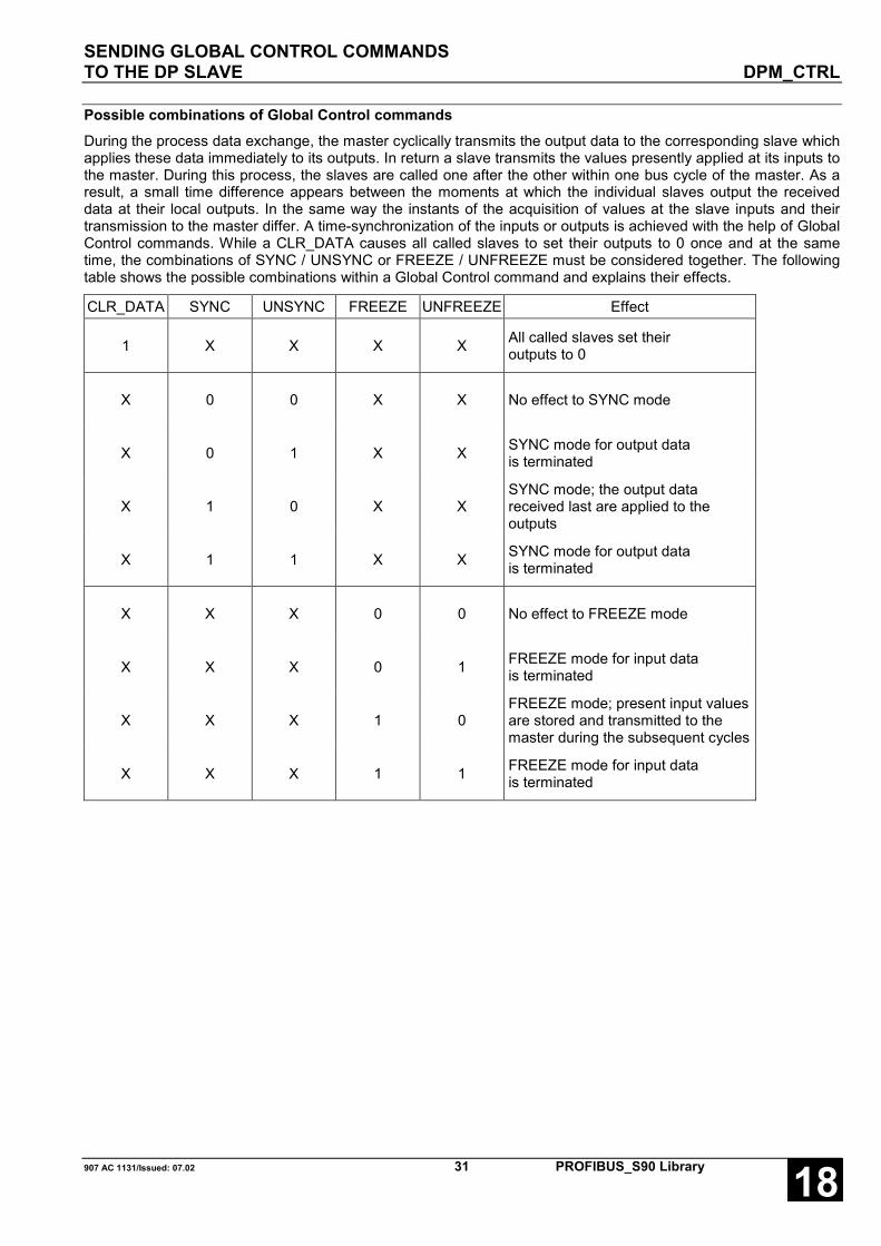
SENDING GLOBAL CONTROL COMMANDSTO THE DP SLAVE DPM_CTRL
907 AC 1131/Issued: 07.02 31 PROFIBUS_S90 Library 18
Possible combinations of Global Control commandsDuring the process data exchange, the master cyclically transmits the output data to the corresponding slave whichapplies these data immediately to its outputs. In return a slave transmits the values presently applied at its inputs tothe master. During this process, the slaves are called one after the other within one bus cycle of the master. As aresult, a small time difference appears between the moments at which the individual slaves output the receiveddata at their local outputs. In the same way the instants of the acquisition of values at the slave inputs and theirtransmission to the master differ. A time-synchronization of the inputs or outputs is achieved with the help of GlobalControl commands. While a CLR_DATA causes all called slaves to set their outputs to 0 once and at the sametime, the combinations of SYNC / UNSYNC or FREEZE / UNFREEZE must be considered together. The followingtable shows the possible combinations within a Global Control command and explains their effects.
CLR_DATA SYNC UNSYNC FREEZE UNFREEZE Effect
1 X X X X All called slaves set their outputs to 0
X 0 0 X X No effect to SYNC mode
X 0 1 X X SYNC mode for output data is terminated
X 1 0 X X SYNC mode; the output data received last are applied to the outputs
X 1 1 X X SYNC mode for output data is terminated
X X X 0 0 No effect to FREEZE mode
X X X 0 1 FREEZE mode for input data is terminated
X X X 1 0 FREEZE mode; present input values are stored and transmitted to the master during the subsequent cycles
X X X 1 1 FREEZE mode for input data is terminated
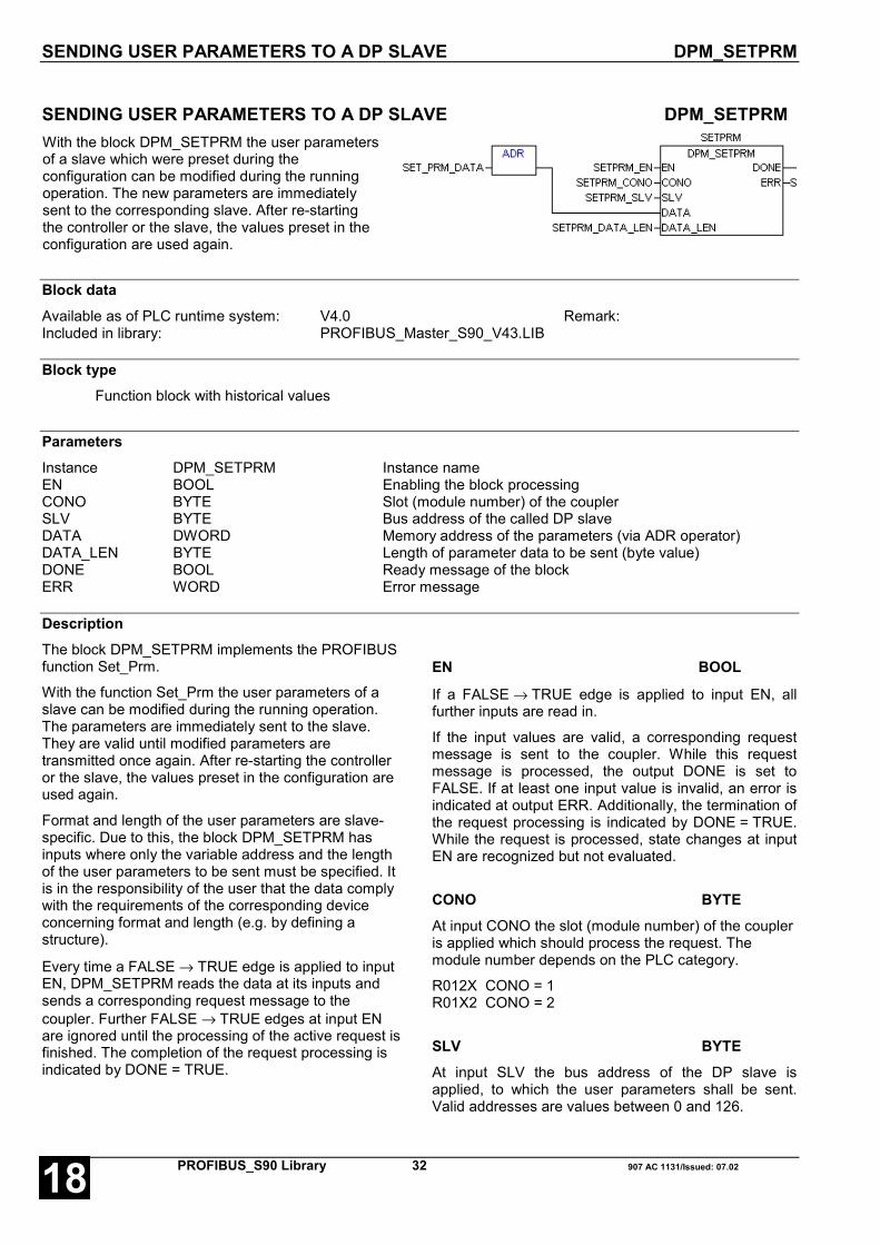
SENDING USER PARAMETERS TO A DP SLAVE DPM_SETPRM
PROFIBUS_S90 Library 32 907 AC 1131/Issued: 07.0218
SENDING USER PARAMETERS TO A DP SLAVE DPM_SETPRMWith the block DPM_SETPRM the user parametersof a slave which were preset during theconfiguration can be modified during the runningoperation. The new parameters are immediatelysent to the corresponding slave. After re-startingthe controller or the slave, the values preset in theconfiguration are used again.
Block dataAvailable as of PLC runtime system: V4.0 Remark:Included in library: PROFIBUS_Master_S90_V43.LIB
Block typeFunction block with historical values
ParametersInstance DPM_SETPRM Instance nameEN BOOL Enabling the block processingCONO BYTE Slot (module number) of the couplerSLV BYTE Bus address of the called DP slaveDATA DWORD Memory address of the parameters (via ADR operator)DATA_LEN BYTE Length of parameter data to be sent (byte value)DONE BOOL Ready message of the blockERR WORD Error message
DescriptionThe block DPM_SETPRM implements the PROFIBUSfunction Set_Prm.
With the function Set_Prm the user parameters of aslave can be modified during the running operation.The parameters are immediately sent to the slave.They are valid until modified parameters aretransmitted once again. After re-starting the controlleror the slave, the values preset in the configuration areused again.
Format and length of the user parameters are slave-specific. Due to this, the block DPM_SETPRM hasinputs where only the variable address and the lengthof the user parameters to be sent must be specified. Itis in the responsibility of the user that the data complywith the requirements of the corresponding deviceconcerning format and length (e.g. by defining astructure).
Every time a FALSE → TRUE edge is applied to inputEN, DPM_SETPRM reads the data at its inputs andsends a corresponding request message to thecoupler. Further FALSE → TRUE edges at input ENare ignored until the processing of the active request isfinished. The completion of the request processing isindicated by DONE = TRUE.
EN BOOL
If a FALSE → TRUE edge is applied to input EN, allfurther inputs are read in.
If the input values are valid, a corresponding requestmessage is sent to the coupler. While this requestmessage is processed, the output DONE is set toFALSE. If at least one input value is invalid, an error isindicated at output ERR. Additionally, the termination ofthe request processing is indicated by DONE = TRUE.While the request is processed, state changes at inputEN are recognized but not evaluated.
CONO BYTEAt input CONO the slot (module number) of the coupleris applied which should process the request. Themodule number depends on the PLC category.
R012X CONO = 1R01X2 CONO = 2
SLV BYTEAt input SLV the bus address of the DP slave isapplied, to which the user parameters shall be sent.Valid addresses are values between 0 and 126.

SENDING USER PARAMETERS TO A DP SLAVE DPM_SETPRM
907 AC 1131/Issued: 07.02 33 PROFIBUS_S90 Library 18
DATA DWORDAt input DATA the address of the variable from whichon the parameters to be sent are stored is specified viathe address operator ADR. The data format and thelength of the variable itself must be chosen this waythat they correspond to the structure of the userparameters of the slave. It is recommended to define aSTRUCT data type which represents an image of theslave's structure first and then to declare a variable ofthis type. Please note that at this point only the userparameters are to be specified. The standardparameters cannot be modified during the runningoperation. The standard parameter settings specifiedduring configuration are automatically completed by theblock.
DATA_LEN BYTEThe input DATA_LEN is used to inform the block aboutthe length (number of bytes) of the user parameters tobe transmitted. The maximum length is 237 bytes.
DONE BOOLThe output DONE reflects the state of the requestprocessing. If the block is trigged by a FALSE → TRUEedge at input EN, DONE is set to FALSE in order toindicate that the request processing is running. Ifprocessing is finished, DONE is set to TRUE.
The values applied at the block outputs are only valid ifDONE = TRUE. The parameters were only transmittedcorrectly if also ERR = 0. If ERR is not 0, an erroroccurred.
ERR WORDAt the output ERR an error identifier is applied if aninvalid value was applied to an input or if an erroroccurred during the request processing. ERR hasalways to be considered together with the outputDONE. The value applied at ERR is only valid ifDONE = TRUE. The error message encoding at theoutput ERR applies to all PROFIBUS blocks and isexplained following the block descriptions.
Function call in ILLD SETPRM_DATAADRST SETPRM_DATA_ADRCAL SETPRM
(EN := SETPRM_EN,CONO := SETPRM_CONO,SLV := SETPRM_SLV,DATA := SETPRM_DATA,DATA_LEN := SETPRM_DATA_LEN)
LD SETPRM.DONEST SETPRM_DONELD SETPRM.ERRST SETPRM_ERR
Note: In IL, the function call has to be performed inone line.
Function call in STSETPRM
(EN := SETPRM_EN,CONO := SETPRM_CONO,SLV := SETPRM_SLV,DATA := SETPRM_DATA,DATA_LEN := SETPRM_DATA_LEN);
SETPRM_DONE := SETPRM.DONE;SETPRM_ERR := SETPRM.ERR;

READING THE INPUT DATA OF A SLAVEWHICH IS NOT ASSIGNED TO THE MASTER DPM_READ_INPUT
PROFIBUS_S90 Library 34 907 AC 1131/Issued: 07.0218
READING THE INPUT DATA OF A SLAVEWHICH IS NOT ASSIGNED TO THE MASTER DPM_READ_INPUTWith the block DPM_READ_INPUT even the inputdata of those slaves can be read which are notassigned to the master, i.e. which were notconfigured by the master.
Block dataAvailable as of PLC runtime system: V4.0 Remark:Included in library: PROFIBUS_Master_S90_V43.LIB
Block typeFunction block with historical values
ParametersInstance DPM_READ_INPUT Instance nameEN BOOL Enabling the block processingCONO BYTE Slot (module number) of the couplerSLV BYTE DP slave addressDATA DWORD Memory address for input data (via ADR operator)DONE BOOL Ready message of the blockERR WORD Error messageDATA_LEN BYTE Length of the read input data
DescriptionThe block DPM_READ_INPUT implements the acyclicPROFIBUS function DDLM_Read_Input. Using thisfunction the master can also read the input data ofthose slaves which are assigned to other masters.DPM_READ_INPUT works outside the cyclic processdata exchange.
Every time a FALSE → TRUE edge is applied to inputEN, DPM_READ_INPUT reads the data at the inputsand sends a corresponding request message to thecoupler. Further FALSE → TRUE edges at input ENare ignored until the processing of the active request isfinished. The completion of the request processing isindicated by DONE = TRUE.
EN BOOL
If a FALSE → TRUE edge is applied to input EN, allfurther inputs are read in.
If the input values are valid, a corresponding requestmessage is sent to the coupler. While this requestmessage is processed, the output DONE is set toFALSE. If at least one input value is invalid, an error isindicated at output ERR. Additionally, the termination ofthe request processing is indicated by DONE = TRUE.While the request is processed, state changes at inputEN are recognized but not evaluated.
CONO BYTEAt input CONO the slot (module number) of the coupleris applied which should process the request. Themodule number depends on the PLC category.
R012X CONO = 1R01X2 CONO = 2
SLV BYTEAt input SLV the bus address of the DP slave whoseinput data are to be read is applied.
DATA DWORDThe address of the variable which shall be used tostore the received input data is specified at the inputDATA via the address operator ADR. The size of thevariable itself must be chosen accordingly so that it isable to hold all input data of the slave (e.g. BYTEarray). Furthermore, the format (BYTE, WORD, etc.) ofthe slave inputs must be considered. If the slave hasmixed inputs of different types, it is recommended tofirst define a STRUCT data type which represents animage of the slave's structure (see I/O configuration ofthe slave) and then to declare a variable of this type.
READING THE INPUT DATA OF A SLAVEWHICH IS NOT ASSIGNED TO THE MASTER DPM_READ_INPUT
907 AC 1131/Issued: 07.02 35 PROFIBUS_S90 Library 18
DONE BOOLThe output DONE reflects the state of the requestprocessing. If the block is trigged by a FALSE → TRUEedge at input EN, DONE is set to FALSE in order toindicate that the request processing is running. Ifprocessing is finished, DONE is set to TRUE.
The values applied at the block outputs and the inputdata of the slave are only valid if DONE = TRUE. Theinput data were only read correctly if also ERR = 0. IfERR is not 0, an error occurred.
ERR WORDAt the output ERR an error identifier is applied if aninvalid value was applied to an input or if an erroroccurred during the request processing. ERR has
always to be considered together with the outputDONE. The value applied at ERR is only valid ifDONE = TRUE. The error message encoding at theoutput ERR applies to all PROFIBUS blocks and isexplained after the block descriptions.
DATA_LEN BYTEThe output DATA_LEN displays the length (in bytes) ofthe input data read by the slave. DATA_LEN is onlyvalid if DONE = TRUE and ERR = 0. If DATA_LENcontains a value X which is not 0, the block has storedX bytes of input data in the variable specified withDATA. For instance, if DATA is a byte array with a startindex of 1, the valid input data of the slave arecontained in the entries DATA[1] to DATA[X].
Function call in ILLD READ_INPUT_DATAADRST READ_INPUT_DATA_ADRCAL READ_INPUT
(EN := READ_INPUT_EN,CONO := READ_INPUT_CONO,SLV := READ_INPUT_SLV,DATA := READ_INPUT_DATA,)
LD READ_INPUT.DONEST READ_INPUT_DONELD READ_INPUT.ERRST READ_INPUT_ERRLD READ_INPUT.DATA_LENST READ_INPUT_DATA_LEN
Note: In IL, the function call has to be performed inone line.
Function call in STREAD_INPUT
(EN := RAED_INPUT_EN,CONO := RAED_INPUT_CONO,SLV := RAED_INPUT_SLV,DATA := ADR(RAED_INPUT_DATA));
READ_INPUT_DONE:= READ_INPUT.DONE;READ_INPUT_ERR:= READ_INPUT.ERR;READ_INPUT_DATA_LEN:= READ_INPUT.DATA_LEN;
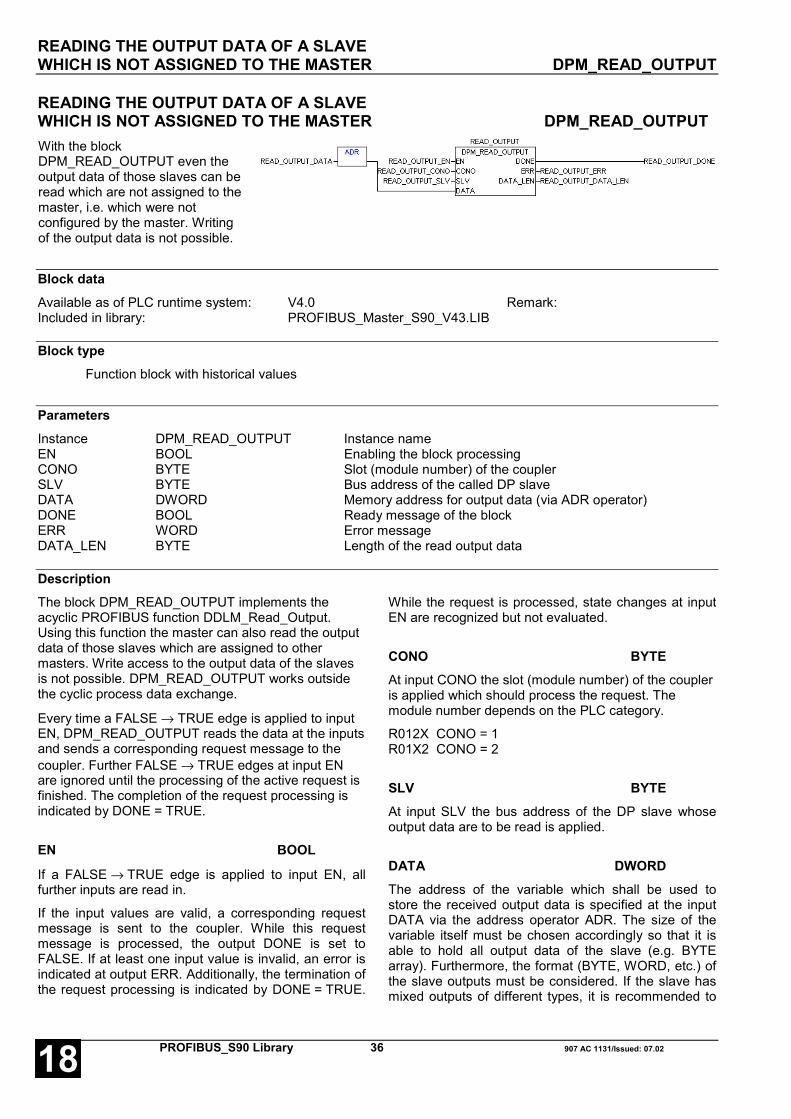
READING THE OUTPUT DATA OF A SLAVEWHICH IS NOT ASSIGNED TO THE MASTER DPM_READ_OUTPUT
PROFIBUS_S90 Library 36 907 AC 1131/Issued: 07.0218
READING THE OUTPUT DATA OF A SLAVEWHICH IS NOT ASSIGNED TO THE MASTER DPM_READ_OUTPUTWith the blockDPM_READ_OUTPUT even theoutput data of those slaves can beread which are not assigned to themaster, i.e. which were notconfigured by the master. Writingof the output data is not possible.
Block dataAvailable as of PLC runtime system: V4.0 Remark:Included in library: PROFIBUS_Master_S90_V43.LIB
Block typeFunction block with historical values
ParametersInstance DPM_READ_OUTPUT Instance nameEN BOOL Enabling the block processingCONO BYTE Slot (module number) of the couplerSLV BYTE Bus address of the called DP slaveDATA DWORD Memory address for output data (via ADR operator)DONE BOOL Ready message of the blockERR WORD Error messageDATA_LEN BYTE Length of the read output data
DescriptionThe block DPM_READ_OUTPUT implements theacyclic PROFIBUS function DDLM_Read_Output.Using this function the master can also read the outputdata of those slaves which are assigned to othermasters. Write access to the output data of the slavesis not possible. DPM_READ_OUTPUT works outsidethe cyclic process data exchange.
Every time a FALSE → TRUE edge is applied to inputEN, DPM_READ_OUTPUT reads the data at the inputsand sends a corresponding request message to thecoupler. Further FALSE → TRUE edges at input ENare ignored until the processing of the active request isfinished. The completion of the request processing isindicated by DONE = TRUE.
EN BOOL
If a FALSE → TRUE edge is applied to input EN, allfurther inputs are read in.
If the input values are valid, a corresponding requestmessage is sent to the coupler. While this requestmessage is processed, the output DONE is set toFALSE. If at least one input value is invalid, an error isindicated at output ERR. Additionally, the termination ofthe request processing is indicated by DONE = TRUE.
While the request is processed, state changes at inputEN are recognized but not evaluated.
CONO BYTEAt input CONO the slot (module number) of the coupleris applied which should process the request. Themodule number depends on the PLC category.
R012X CONO = 1R01X2 CONO = 2
SLV BYTEAt input SLV the bus address of the DP slave whoseoutput data are to be read is applied.
DATA DWORDThe address of the variable which shall be used tostore the received output data is specified at the inputDATA via the address operator ADR. The size of thevariable itself must be chosen accordingly so that it isable to hold all output data of the slave (e.g. BYTEarray). Furthermore, the format (BYTE, WORD, etc.) ofthe slave outputs must be considered. If the slave hasmixed outputs of different types, it is recommended to

READING THE OUTPUT DATA OF A SLAVEWHICH IS NOT ASSIGNED TO THE MASTER DPM_READ_OUTPUT
907 AC 1131/Issued: 07.02 37 PROFIBUS_S90 Library 18
first define a STRUCT data type which represents animage of the slave's output structure (see I/Oconfiguration of the slave) and then to declare avariable of this type.
DONE BOOLThe output DONE reflects the state of the requestprocessing. If the block is trigged by a FALSE → TRUEedge at input EN, DONE is set to FALSE in order toindicate that the request processing is running. Ifprocessing is finished, DONE is set to TRUE.
The values applied at the block outputs and the outputdata of the slave are only valid if DONE = TRUE. Theoutput data were only read correctly if also ERR = 0. IfERR is not 0, an error occurred.
ERR WORDAt the output ERR an error identifier is applied if aninvalid value was applied to an input or if an error
occurred during the request processing. ERR hasalways to be considered together with the outputDONE. The value applied at ERR is only valid ifDONE = TRUE. The error message encoding at theoutput ERR applies to all PROFIBUS blocks and isexplained after the block descriptions.
DATA_LEN BYTEThe output DATA_LEN displays the length (in bytes) ofthe output data read by the slave. DATA_LEN is onlyvalid if DONE = TRUE and ERR = 0. If DATA_LENcontains a value X which is not 0, the block has storedX bytes of output data in the variable specified withDATA. For instance, if DATA is a byte array with a startindex of 1, the valid output data of the slave arecontained in the entries DATA[1] to DATA[X].
Function call in ILLD READ_OUTPUT_DATAADRST READ_OUTPUT_DATA_ADRCAL READ_OUTPUT
(EN := READ_OUTPUT_EN,CONO := READ_OUTPUT_CONO,SLV := READ_OUTPUT_SLV,DATA := READ_OUTPUT_DATA,)
LD READ_OUTPUT.DONEST READ_OUTPUT_DONELD READ_OUTPUT.ERRST READ_OUTPUT_ERRLD READ_OUTPUT.DATA_LENST READ_OUTPUT_DATA_LEN
Note: In IL, the function call has to be performed inone line.
Function call in STREAD_OUTPUT
(EN := READ_OUTPUT_EN,CONO := READ_OUTPUT_CONO,SLV := READ_OUTPUT_SLV,DATA := ADR(READ_OUTPUT_DATA));
READ_OUTPUT_DONE:= READ_OUTPUT.DONE;READ_OUTPUT_ERR:= READ_OUTPUT.ERR;READ_OUTPUT_DATA_LEN:= READ_OUTPUT.DATA_LEN;
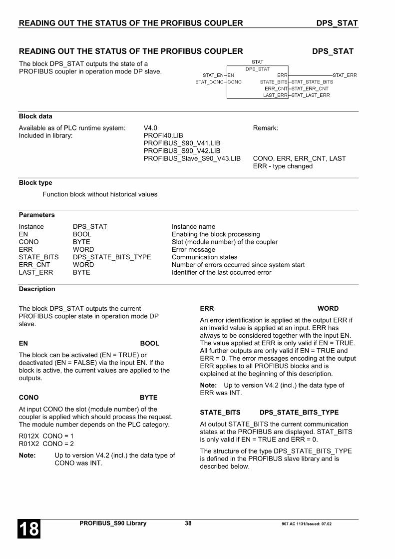
READING OUT THE STATUS OF THE PROFIBUS COUPLER DPS_STAT
PROFIBUS_S90 Library 38 907 AC 1131/Issued: 07.0218
READING OUT THE STATUS OF THE PROFIBUS COUPLER DPS_STATThe block DPS_STAT outputs the state of aPROFIBUS coupler in operation mode DP slave.
Block dataAvailable as of PLC runtime system: V4.0 Remark:Included in library: PROFI40.LIB
PROFIBUS_S90_V41.LIBPROFIBUS_S90_V42.LIBPROFIBUS_Slave_S90_V43.LIB CONO, ERR, ERR_CNT, LAST
ERR - type changed
Block typeFunction block without historical values
ParametersInstance DPS_STAT Instance nameEN BOOL Enabling the block processingCONO BYTE Slot (module number) of the couplerERR WORD Error messageSTATE_BITS DPS_STATE_BITS_TYPE Communication statesERR_CNT WORD Number of errors occurred since system startLAST_ERR BYTE Identifier of the last occurred error
Description
The block DPS_STAT outputs the currentPROFIBUS coupler state in operation mode DPslave.
EN BOOLThe block can be activated (EN = TRUE) ordeactivated (EN = FALSE) via the input EN. If theblock is active, the current values are applied to theoutputs.
CONO BYTEAt input CONO the slot (module number) of thecoupler is applied which should process the request.The module number depends on the PLC category.
R012X CONO = 1R01X2 CONO = 2
Note: Up to version V4.2 (incl.) the data type ofCONO was INT.
ERR WORDAn error identification is applied at the output ERR ifan invalid value is applied at an input. ERR hasalways to be considered together with the input EN.The value applied at ERR is only valid if EN = TRUE.All further outputs are only valid if EN = TRUE andERR = 0. The error messages encoding at the outputERR applies to all PROFIBUS blocks and isexplained at the beginning of this description.
Note: Up to version V4.2 (incl.) the data type ofERR was INT.
STATE_BITS DPS_STATE_BITS_TYPEAt output STATE_BITS the current communicationstates at the PROFIBUS are displayed. STAT_BITSis only valid if EN = TRUE and ERR = 0.
The structure of the type DPS_STATE_BITS_TYPEis defined in the PROFIBUS slave library and isdescribed below.

READING OUT THE STATUS OF THE PROFIBUS COUPLER DPS_STAT
907 AC 1131/Issued: 07.02 39 PROFIBUS_S90 Library 18
ERR_CNT WORDAt output ERR_CNT the number of errors occurredsince the last coupler reset is output. ERR_CNT isonly valid if EN = TRUE and ERR = 0.
Note: Up to version V4.2 (incl.) the data type ofERR_CNT was INT.
LAST_ERR BYTEAt output LAST_ERR the identifier of the lastoccurred error is output. The error encoding inLAST_ERR is described below. LAST_ERR is onlyvalid if EN = TRUE and ERR = 0.
Note: Up to version V4.2 (incl.) the data type ofLAST_ERR was INT.
Function call in ILCAL STAT(EN := STAT_EN,CONO := STAT_CONO)
LD STAT.ERRST STAT_ERRLD STAT.STATE_BITSST STAT_STATE_BITSLD STAT.ERR_CNTST STAT_ERR_CNTLD STAT.LAST_ERRST STAT_LAST_ERR
Note: In IL, the function call has to be performed inone line.
Function call in STSTAT
(EN :=STAT_EN,CONO :=STAT_CONO);
STAT_ERR :=STAT.ERR;STAT_STATE_BITS :=STAT.STATE_BITS;STAT_ERR_CNT :=STAT.ERR_CNT;STAT_LAST_ERR :=STAT.LAST_ERR;

READING OUT THE STATUS OF THE PROFIBUS COUPLER DPS_STAT
PROFIBUS_S90 Library 40 907 AC 1131/Issued: 07.0218
STATE_BITS DPS_STATE_BITS_TYPEThe structure STATE_BITS includes five booleanvariables which display the different coupler states.Within the PROFIBUS slave library the data typeDPS_STATE_BITS_TYPE is declared as follows:
TYPE DPS_STATE_BITS_TYPE:STRUCT
INIT: BOOL;RUN: BOOL;STATIC_DIAG: BOOL;DATA_EXCH: BOOL;NEW_PRM: BOOL;
END_STRUCTEND_TYPE
INIT BOOLIf this bit is set to TRUE, an initialization erroroccurred. In normal operation INIT should be FALSE.If this is not the case, the parameter andconfiguration data have to be checked.
RUN BOOLThis bit is set to TRUE, if the initialization phase hasbeen completed successfully and the coupler is readyfor communication via PROFIBUS. An error hasoccurred, if RUN is FALSE for longer time.
STATIC_DIAG BOOLThis bit is set to TRUE, if the coupler itself has astatic diagnosis according to the PROFIBUSstandard. If at least one standard diagnosis causeaccording to the standard occurred (see blockDPM_SLVDIAG), the coupler independently sends adiagnosis message via the bus. Until a staticdiagnosis of the coupler exists, no I/O data areexchanged with the DP master.
DATA_EXCH BOOLIf this bit is set to TRUE, the cyclic I/O data exchangebetween coupler and DP master is performed. Innormal operation DATA_EXCH should always beTRUE provided that STATIC_DIAG is not set toTRUE.
NEW_PRM BOOLNEW_PRM is set to TRUE, if the coupler hasreceived new parameter data from the DP master.

READING OUT THE STATUS OF THE PROFIBUS COUPLER DPS_STAT
907 AC 1131/Issued: 07.02 41 PROFIBUS_S90 Library 18
LAST_ERR Encoding of the error messages
LAST_ERR Meaning Error source Remedy
52 Invalid bus address configured Configuration
Valid bus addresses 1 - 125Check configuration data for coupler inthe project and/or reload program tocontroller
53 Expect warm start Coupler Contact ABB
54 Received configuration data containinvalid I/O module Configuration
An I/O module was configured which isnot entered in the GSD fileCheck configuration data for coupler inthe project and/or reload program tocontroller
55 Received configuration data containI/O module with invalid length Configuration
An I/O module was configured withoutlengthCheck configuration data for coupler inthe project and/or reload program tocontroller
61 No address switches Coupler Contact ABB
63 Unknown process data handshake Controlsystem
Supply voltage OFF/ON, otherwisecontact ABB
70 Received configuration data containinvalid I/O data length Configuration
Add I/O modules to coupler configurationdata (if not configured) or reduce I/O dataoverall length (if overall length exceeded)and reload program to controller
72 Invalid DPV1 buffer forDP master class 1 communication Coupler Contact ABB
73 Invalid DPV1 buffer forDP master class 2 communication Coupler Contact ABB
74 ASIC not in offline mode duringinitialization Coupler Contact ABB
75 ASIC insufficient memory Coupler Contact ABB 76 Invalid size I/O data buffer Coupler Contact ABB 77 Invalid size diagnosis buffer Coupler Contact ABB 78 Invalid size parameter buffer Coupler Contact ABB 79 Invalid size configuration data buffer Coupler Contact ABB 80 Invalid size SSA buffer Coupler Contact ABB
210 Error while reading database Configuration/Coupler
Reload program with configuration datato controller

SENDING THE ERROR FLAGS OF THE BASIC UNITFOR AN EXTENDED DIAGNOSIS DPS_EXTDIAG
PROFIBUS_S90 Library 42 907 AC 1131/Issued: 07.0218
SENDING THE ERROR FLAGS OF THE BASIC UNITFOR AN EXTENDED DIAGNOSIS DPS_EXTDIAGThe block DPS_EXTDIAG generates anextended diagnosis message from the errorflags of the basic unit and sends this messageto the master.
Block dataAvailable as of PLC runtime system: V4.0 Remark:Included in library: PROFIBUS_Slave_S90_V43.LIB
Block typeFunction block without historical values
ParametersInstance DPS_EXTDIAG Instance nameEN BOOL Enabling the block processingCONO BYTE Slot (module number) of the couplerDONE BOOL Ready message of the blockERR WORD Error message
Description
The block DPS_EXTDIAG generates an extendeddiagnosis message according to the PROFIBUSstandard. For this, it monitors the state of the sumerror flag %MX255.10. If this flag is set (TRUE), thedetailed information is entered into the diagnosistelegram according to the states of the error classflags %MX255.11 to %MX255.14. If thecorresponding flag is set, the detailed information isentered into the telegram. Otherwise thecorresponding range in the diagnosis data is set tozero. Furthermore, the status word %IW1007.15 isalways sent. The extended diagnosis data aremarked as device-specific data and have always atotal length of 26 bytes. The PROFIBUS standarddiagnosis data are automatically completed.
If a FK1 or FK2 error occurred (%MX255.11 = TRUEor %MX255.12 = TRUE), the diagnosis information ismarked as an error message and can be evaluatedaccordingly in the master. If only a light error (FK3,%MX255.13 = TRUE) or a warning (FK4,%MX255.14 = TRUE) occurred, the diagnosisinformation is marked as a status message.
The extended diagnosis is sent until the sum errorflag is acknowledged, i.e. until %MX255.10 is set toFALSE. The structure of the diagnosis data isexplained later in this section.
EN BOOLThe block can be activated (EN = TRUE) ordeactivated (EN = FALSE) via the input EN. If theblock is active, the state of the sum error flag%MX255.10 is monitored. If necessary, extendeddiagnosis information are sent to the master.
CONO BYTEAt input CONO the slot (module number) of thecoupler is applied which should process the request.The module number depends on the PLC category.
R012X CONO = 1R01X2 CONO = 2
DONE BOOLThe output DONE indicates whether the block hassent (TRUE) an extended diagnosis message duringthe current program cycle or not (FALSE).

SENDING THE ERROR FLAGS OF THE BASIC UNITFOR AN EXTENDED DIAGNOSIS DPS_EXTDIAG
907 AC 1131/Issued: 07.02 43 PROFIBUS_S90 Library 18
ERR WORDAn error identification is applied at the output ERR ifan invalid value is applied at an input. ERR hasalways to be considered together with the input EN.The value applied at ERR is only valid if EN = TRUE.The error message encoding at the output ERRapplies to all PROFIBUS blocks and is explainedfollowing the block descriptions.
Function call in ILCAL EXTDIAG(EN := EXTDIAG_EN,CONO := EXTDIAG_CONO)
LD EXTDIAG.DONEST EXTDIAG_DONELD EXTDIAG.ERRST EXTDIAG_ERR
Note: In IL, the function call has to be performed inone line.
Function call in STEXTDIAG
(EN :=EXTDIAG_EN,CONO :=EXTDIAG_CONO);
EXTDIAG_DONE :=EXTDIAG.DONE;EXTDIAG_ERR :=EXTDIAG.ERR;

SENDING THE ERROR FLAGS OF THE BASIC UNITFOR AN EXTENDED DIAGNOSIS DPS_EXTDIAG
PROFIBUS_S90 Library 44 907 AC 1131/Issued: 07.0218
LAST_ERR Encoding of the error messagesThe following table gives an overview of the structure of the diagnosis data according to PROFIBUS standard (6bytes) and the extended diagnosis data (26 bytes).
PROFIBUS standard diagnosis data
Byte Designation Meaning 1 Stationstatus_1 See DPM_SLVDIAG 2 Stationstatus_2 See DPM_SLVDIAG 3 Stationstatus_3 See DPM_SLVDIAG 4 Stationstatus_4 See DPM_SLVDIAG 5 Identification number, high byte Identification number of the slave 6 Identification number, low byte Identification number of the slaveExtended diagnosis data
Byte Designation Meaning
1 Header device-specific diagnosis Identification and length of the device-specific diagnosis,see DPM_SLVDIAG
...2 0 always 0 3 %MW1254.0 (low byte) FK1 error identifier 4 %MW1254.0 (high byte) FK1 error identifier 5 %MW1254.1 (low byte) FK1 detailed information 1 6 %MW1254.1 (high byte) FK1 detailed information 1 7 %MW1254.8 (low byte) FK2 error identifier 8 %MW1254.8 (high byte) FK2 error identifier 9 %MW1254.9 (low byte) FK2 detailed information 1 10 %MW1254.9 (high byte) FK2 detailed information 1 11 %MW1254.10 (low byte) FK2 detailed information 2..12 %MW1254.10 (high byte) FK2 detailed information 2 13 %MW1255.0 (low byte) FK3 error identifier 14 %MW1255.0 (high byte) FK3 error identifier 15 %MW1255.1 (low byte) FK3 detailed information 1 16 %MW1255.1 (high byte) FK3 detailed information 1 17 %MW1255.2 (low byte) FK3 detailed information 2 18 %MW1255.2 (high byte) FK3 detailed information 2 19 %MW1255.8 (low byte) FK4 error identifier 20 %MW1255.8 (high byte) FK4 error identifier 21 %MW1255.9 (low byte) FK4 detailed information 1 22 %MW1255.9 (high byte) FK4 detailed information 1 23 %MW1255.10 (low byte) FK4 detailed information 2 24 %MW1255.10 (high byte) FK4 detailed information 2 25 %IW1007.15 (low byte) Status word 26 %IW1007.15 (high byte) Status word

READING OUT THE USER PARAMETERS DPS_GETPRM
907 AC 1131/Issued: 07.02 45 PROFIBUS_S90 Library 18
READING OUT THE USER PARAMETERS DPS_GETPRMWith the block DPS_GETPRM thecurrent user parameters of the slavecan be read.
Block dataAvailable as of PLC runtime system: V4.0 Remark:Included in library: PROFIBUS_Slave_S90_V43.LIB
Block typeFunction block with historical values
ParametersInstance DPS_GETPRM Instance nameEN BOOL Enabling the block processingCONO BYTE Slot (module number) of the couplerDONE BOOL Ready message of the slaveERR WORD Error messageBOOL1 BOOL Switch 1, BOOL parameterBOOL2 BOOL Switch 2, BOOL parameterBOOL3 BOOL Switch 3, BOOL parameterBOOL4 BOOL Switch 4, BOOL parameterBOOL5 BOOL Switch 5, BOOL parameterBOOL6 BOOL Switch 6, BOOL parameterBOOL7 BOOL Switch 7, BOOL parameterBOOL8 BOOL Switch 8, BOOL parameterBYTE1 BYTE Value byte 1, BYTE parameterBYTE2 BYTE Value byte 2, BYTE parameterINT1 INT Integer value 1, INT parameterINT2 INT Integer value 1, INT parameter
DescriptionThe block DPS_GETPRM implements the PROFIBUSfunction Get_Prm.
With the block DPS_GETPRM the current userparameters of the slave can be read. In addition to the7 bytes of standard parameters the master sends 10bytes of user parameters to the slave. The standardparameters are defined by the configuration and cannotbe modified. The first 3 bytes of the user parametersare intended for internal use and cannot be modified aswell. The remaining user parameters divide in 8 BOOL
values, 2 BYTE values and 2 INT values. Theseparameters can be used as desired.
The default values of the user parameters are presetduring the slave configuration in the master. Thesevalues are sent once to the slave every time the slaveis taken into operation by the master (restart of themaster or of the slave). With the help of the PROFIBUSfunction Set_Prm (see also DPM_SETPRM) the userparameters can be used by the master during the
READING OUT THE USER PARAMETERS DPS_GETPRM
PROFIBUS_S90 Library 46 907 AC 1131/Issued: 07.0218
running operation and thus they can be used asapplication specific commands.
The reception of new parameter data is indicated at theoutput NEW_PRM of the block DPS_STAT.
Every time a FALSE → TRUE edge is applied to inputEN, DPM_GET_PRM reads the values at the inputsand then reads the current user parameters from thecoupler. Further FALSE → TRUE edges at input ENare ignored until the processing of the active requestsis finished. The completion of the request processing isindicated by DONE = TRUE.
EN BOOL
If a FALSE → TRUE edge is applied to input EN, allfurther inputs are read in.
If the input values are valid, a corresponding requestmessage is sent to the coupler. While this requestmessage is processed, the output DONE is set toFALSE. If at least one input value is invalid, an error isindicated at output ERR. Additionally, the termination ofthe request processing is indicated by DONE = TRUE.While the request is processed, state changes at inputEN are recognized but not evaluated.
CONO BYTEAt input CONO the slot (module number) of the coupleris applied which should process the request. Themodule number depends on the PLC category.
R012X CONO = 1R01X2 CONO = 2
DONE BOOL
The output DONE reflects the state of the requestprocessing. If the block is trigged by a FALSE → TRUEedge at input EN, DONE is set to FALSE in order toindicate that the request processing is running. If theprocessing is finished, DONE is set to TRUE for onecycle.
The values applied at the block outputs are only valid ifDONE = TRUE. The parameters applied at the blockoutputs are only valid if also ERR = 0. If ERR is not 0,an error occurred.
ERR WORDAt the output ERR an error identifier is applied if aninvalid value was applied to an input or if an erroroccurred during the request processing. ERR hasalways to be considered together with the outputDONE. The value applied at ERR is only valid ifDONE = TRUE. The error message encoding at theoutput ERR applies to all PROFIBUS blocks and isexplained after the block descriptions.
BOOL1 ... BOOL8 BOOLAt the outputs BOOL1 to BOOL8 the current states ofthe boolean user parameters (switches) are indicated.These are only valid if DONE = TRUE and ERR = 0.
BYTE1 ... BYTE2 BYTEAt the outputs BYTE1 and BYTE2 the current values ofthe BYTE user parameters are displayed. These areonly valid if DONE = TRUE and ERR = 0.
INT1 ... INT2 INTAt the outputs INT1 and INT2 the current values of theINT user parameters are displayed. These are onlyvalid if DONE = TRUE and ERR = 0.

READING OUT THE USER PARAMETERS DPS_GETPRM
907 AC 1131/Issued: 07.02 47 PROFIBUS_S90 Library 18
Function call in ILCAL GETPRM
(EN := GETPRM_EN,CONO := GETPRM)
LD GETPRM.DONEST GETPRM_DONELD GETPRM.ERRST GETPRM_ERRLD GETPRM.BOOL1ST GETPRM_BOOL1LD GETPRM.BOOL2ST GETPRM_BOOL2LD GETPRM.BOOL3ST GETPRM_BOOL3LD GETPRM.BOOL4ST GETPRM_BOOL4LD GETPRM.BOOL5ST GETPRM_BOOL5LD GETPRM.BOOL6ST GETPRM_BOOL6LD GETPRM.BOOL7ST GETPRM_BOOL7LD GETPRM.BOOL8ST GETPRM_BOOL8LD GETPRM.BYTE1ST GETPRM_BYTE1LD GETPRM.BYTE2ST GETPRM_BYTE2LD GETPRM.INT1ST GETPRM_INT1LD GETPRM.INT2ST GETPRM_INT2
Note: In IL, the function call has to be performed inone line.
Function call in STGETPRM
(EN := GETPRM_EN,CONO := GETPRM_CONO);
GETPRM_DONE := GETPRM.DONE;GETPRM_ERR := GETPRM.ERR;GETPRM_BOOL1 := GETPRM.BOOL1;GETPRM_BOOL2 := GETPRM.BOOL2;GETPRM_BOOL3 := GETPRM.BOOL3;GETPRM_BOOL4 := GETPRM.BOOL4;GETPRM_BOOL5 := GETPRM.BOOL5;GETPRM_BOOL6 := GETPRM.BOOL6;GETPRM_BOOL7 := GETPRM.BOOL7;GETPRM_BOOL8 := GETPRM.BOOL8;GETPRM_BYTE1 := GETPRM.BYTE1;GETPRM_BYTE1 := GETPRM.BYTE1;GETPRM_INT1 := GETPRM.INT1;GETPRM_INT2 := GETPRM.INT2;

READING OUT THE USER PARAMETERS DPS_GETPRM
PROFIBUS_S90 Library 48 907 AC 1131/Issued: 07.0218
907 AC 1131/Issued: 07.02 49 PROFIBUS_S90 Library 18
Glossary
BOOLVariables of the type BOOL can have the values TRUE and FALSE. For this, 8 bit memory space are reserved.
DINTDINT belongs to the integer data types.
The different numerical types are responsible for a different numerical range. For integer data types the followingrange limits are valid:
Type Lower limit Upper limit Memory space
DINT: -2147483648 2147483647 32 bits
Due to this, it is possible that information are lost when converting greater data types to smaller data types.
DWORDDWORD belongs to the integer data types.
The different numerical types are responsible for a different numerical range. For integer data types the followingrange limits are valid:
Type Lower limit Upper limit Memory space
DWORD 0 4294967295 32 bits
Due to this, it is possible that information are lost when converting greater data types to smaller data types.
INTINT belongs to the integer data types.
The different numerical types are responsible for a different numerical range. For integer data types the followingrange limits are valid:
Type Lower limit Upper limit Memory space
INT: -32768 32767 16 bits
Due to this, it is possible that information are lost when converting greater data types to smaller data types.

PROFIBUS_S90 Library 50 907 AC 1131/Issued: 07.0218
WORDWORD belongs to the integer data types.
The different numerical types are responsible for a different numerical range. For integer data types the followingrange limits are valid:
Type Lower limit Upper limit Memory space
WORD 0 65535 16 bits
Due to this, it is possible that information are lost when converting greater data types to smaller data types.
FunctionsFunctions are subroutines which have multiple input parameters and return exactly one result element. Thereturned result can be of an elementary or a derived data type. Due to this, a function may also return an array, astructure, an array of structures and so on.
For the same input parameters, functions always return the same result (they do not have an internal memory).
Therefore, the following rules can be derived:
• Within functions, global variables can neither be read nor written.
• Within functions, absolute operands can neither be read nor written.
• Within functions, function blocks must not be called.
Function blocksFunction blocks are subroutines which can have as many inputs, outputs and internal variables as required. Theyare called from a program or from another function block.
As they can be used several times (with different data records), function blocks (code and interface) can beconsidered as type. When assigning an individual data record (declaration) to the function block, a function blockinstance is generated.
In contrast to functions, function blocks can contain statically local data which are saved from one call to the next.Therefore e.g. counters can be realized which may not forget their counter value. I.e. function blocks can have aninternal memory.
Functions and function blocks differ in two essential points:
• A function block has multiple output parameters, a function only one. The output parameters of functions andfunction blocks differ syntactically.
• In contrast to a function, a function block can have an internal memory.
907 AC 1131/Issued: 07.02 51 PROFIBUS_S90 Library 18
Index
DDPM_COM_ERR_TYPE 23
DPM_CTRL S90 27
DPM_READ_INPUT S90 34
DPM_READ_OUTPUT S90 36
DPM_SETPRM S90 32
DPM_SLVDIAG S90 10, 26, 40
DPM_STAT S90 19
DPM_STATE_BITS_TYPE 22
DPM_SYSDIAG S90 25
DPS_EXTDIAG S90 42
DPS_GETPRM S90 45
DPS_STAT S90 38
OOutput ERR of a PROFIBUS block 5
PPROFI_INFO S90 7
PROFIBUS S90
DPM_CTRL 27
DPM_READ_INPUT 34
DPM_READ_OUTPUT 36
DPM_SETPRM 32
DPM_SLVDIAG 10
DPM_STAT 19
DPM_SYSDIAG 25
DPS_EXTDIAG 42
DPS_GETPRM 45
DPS_STAT 38
PROFI_INFO 7
SSTATIONSTATUS_1_TYPE 13
STATIONSTATUS_2_TYPE 14
STATIONSTATUS_3_TYPE 15

PROFIBUS_S90 Library 52 907 AC 1131/Issued: 07.0218

Software Description Advant Controller 31Intelligent DecentralizedAutomation System
DeviceNetFunction Block Library90 Series
DeviceNet90 Series


907 AC 1131/Issued: 06.02 1 DeviceNet_S90 library 18
Contents
DeviceNet library 2SPECIAL CHARACTERISTICS IN THE DEVICENET LIBRARY .................................. 2COMPONENTS OF THE DEVICENET LIBRARY .................................. 2
Function blocks .................................. 2Data types .................................. 2
ERR - ERROR MESSAGES OF THE DEVICENET BLOCKS .................................. 3Errors at block inputs .................................. 3Execution errors, coupler or slave responses .................................. 3
Overview of blocks arranged according to their call names 4READING INFORMATION ABOUT THE INSTALLEDDEVICENET COUPLERS DEVNET_INFO ........ 5POLLING DIAGNOSTIC DATA FROM A SLAVE DNM_DEVDIAG ....... 7READING THE DEVICENET COUPLER STATUS DNM_STAT ............ 12READING A STATUS SURVEY OF ALL SLAVES DNM_SYSDIAG ..... 18READING AN ATTRIBUTE FROM A SLAVE OBJECT DNM_GET_ATTR...20RESETTING A SLAVE OBJECT DNM_RESET_OBJ 23WRITING AN ATTRIBUTE TO A SLAVE OBJECT DNM_SET_ATTR...25
Glossary 28
Index 30
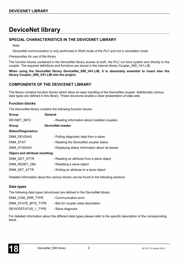
DEVICENET LIBRARY
DeviceNet_S90 library 2 907 AC 1131/Issued: 06.0218
DeviceNet librarySPECIAL CHARACTERISTICS IN THE DEVICENET LIBRARY
Note:
DeviceNet communication is only performed in RUN mode of the PLC and not in simulation mode.
Prerequisites for use of the library
The function blocks contained in the DeviceNet library access to both, the PLC run time system and directly to thecoupler. The required definitions and functions are stored in the internal library Coupler_S90_V41.LIB.
When using the DeviceNet library DeviceNet_S90_V41.LIB, it is absolutely essential to insert also thelibrary Coupler_S90_V41.LIB into the project.
COMPONENTS OF THE DEVICENET LIBRARY
The library contains function blocks which allow an easy handling of the DeviceNet coupler. Additionally variousdata types are defined in this library. These structures enable a clear presentation of data sets.
Function blocksThe DeviceNet library contains the following function blocks:
Group GeneralDEVNET_INFO - Reading information about installed couplers
Group DeviceNet masterStatus/Diagnostics:DNM_DEVDIAG - Polling diagnostic data from a slave
DNM_STAT - Reading the DeviceNet coupler status
DNM_SYSDIAG - Displaying status information about all slaves
Object and attribute handling:DNM_GET_ATTR - Reading an attribute from a slave object
DNM_RESET_OBJ - Resetting a slave object
DNM_SET_ATTR - Writing an attribute to a slave object
Detailed information about the various blocks can be found in the following sections.
Data typesThe following data types (structures) are defined in the DeviceNet library:
DNM_COM_ERR_TYPE - Communication error
DNM_STATE_BITS_TYPE - Bits for coupler state description
DEVICESTATUS_1_TYPE - Slave diagnosis
For detailed information about the different data types please refer to the specific description of the correspondingblock.

ERR - ERROR MESSAGES OF THE DEVICENET BLOCKS
907 AC 1131/Issued: 06.02 3 DeviceNet_S90 library 18
ERR - ERROR MESSAGES OF THE DEVICENET BLOCKS
If the output ERR of a DeviceNet block is unequal to 0, either one of the block input values is invalid or an internalerror occurred during block execution. The error cause can be determined with the help of the following tables.
Errors at block inputs
ERR Meaning
DEC HEX
8193 2001 Invalid value at block input CONO8194 2002 Coupler model in slot CONO does not correspond to the block type8195 2003 No DeviceNet master coupler in slot CONO8196 2004 DeviceNet master coupler in slot CONO is not in OPERATE state8197 2005 Invalid status survey type8198 2006 Invalid slave address at block input8199 2007 Invalid module number at block input8200 2008 Invalid module index at block input8201 2009 Invalid class ID at block input8202 200A Invalid data length at block input
Execution errors, coupler or slave responses
ERR Meaning
DEC HEX
9218 2402 Slave does not have the required resources9224 2408 Service unavailable in slave9225 2409 Slave reports invalid attribute value9227 240B Slave already in request mode9228 240C Object status conflict in slave9230 240E Attribute not writable in slave9231 240F No access release in slave9232 2410 Not possible to run service in current slave status9233 2411 No slave response, timeout9235 2413 Slave has received too few data9236 2414 Attribute not supported in slave9237 2415 Slave has received too many data9238 2416 Object does not exist in slave9239 2417 Too many data, overflow of internal buffer in slave9264 2430 Slave not configured within the coupler, Explicit Message channel not available9266 2432 Coupler reports format error in response telegram of slave9270 2436 Coupler reports that a parallel service is already active9271 2437 Slave address out of valid range9273 2439 Sequence error in fragmented response sequence of slave9377 24A1 Slave address out of valid range9416 24C8 Slave not configured within the coupler, database not found

OVERVIEW OF BLOCKS ARRANGED ACCORDING TO THEIR CALL NAMES
DeviceNet_S90 library 4 907 AC 1131/Issued: 06.0218
Overview of blocks arranged according to their call names
Character description:
FBmV … Function block with historical values
FBoV … Function block without historical values
F … Function
CE name Type Function Page
DEVNET_INFO FBoV Reading information about the installed couplers 5
DNM_GET_ATTR FBmV Reading an attribute from a slave object 20
DNM_DEVDIAG FBmV Reading diagnostic data from a slave (clients) 7
DNM_RESET_OBJ FBmV Resetting a slave object 23
DNM_SET_ATTR FBmV Writing an attribute to a slave object 25
DNM_STAT FBoV Reading the DeviceNet coupler status 12
DNM_SYSDIAG FBoV Reading status surveys about all slaves (clients) 18

READING INFORMATION ABOUT THE INSTALLEDDEVICENET COUPLERS DEVNET_INFO
907 AC 1131/Issued: 06.02 5 DeviceNet_S90 library 18
READING INFORMATION ABOUT THE INSTALLEDDEVICENET COUPLERS DEVNET_INFOThe block DEVNET_INFO outputs coupler relatedinformation. The following items are displayed:coupler type and model, operating mode,manufacturing date, device number and serialnumber as well as firmware designation andfirmware version.
Block typeFunction block without historical values
ParametersInstance DEVNET_INFO Instance nameCONO BYTE Slot (module number) of the couplerERR WORD Error messageTYP STRING(17) Coupler typeMODEL STRING(22) Coupler modelOP_MODE STRING(22) Operating mode of the couplerMAN_DATE DATE Manufacturing date of the couplerDEV_NO DWORD Device number of the couplerSER_NO DWORD Serial number of the couplerFW_NAME STRING(17) Designation of the coupler firmwareFW_VER STRING(17) Version of the coupler firmware
DescriptionThe block DEVNET_INFO is always active. It reads theslot number at the block input CONO and outputs thecorresponding information about the selected couplerat the outputs.
DEVNET_INFO recognizes different coupler types. Forthat reason, the block outputs do not only relate to theDeviceNet coupler.
The block is not intended for usage in normal userprograms. It should be mainly used to support errordiagnostics and maintenance operations.
CONO BYTEThe slot of the coupler (module number) whoseinformation are to be requested is specified at inputCONO. The module number depends on the PLCcategory.
07 SL 97 R015X CONO = 107 SL 97 R01X5 CONO = 2
ERR WORDERR outputs an error ID, if an invalid value is applied toinput CONO. The encoding of the error messages
available at ERR applies to all DeviceNet blocks and isexplained in section "ERR – Error messages of theDeviceNet blocks".
TYP STRING(17)TYP outputs the coupler type (i.e. the coupler design).Different types are recognized by the block.
The DeviceNet coupler has the type TYP = ‚singlemode‘.
If a coupler type cannot be determined, the output TYPis set to ‚unknown‘.

READING INFORMATION ABOUT THE INSTALLEDDEVICENET COUPLERS DEVNET_INFO
DeviceNet_S90 library 6 907 AC 1131/Issued: 06.0218
MODEL STRING(22)MODEL outputs the transfer protocol supported by thecoupler as well as the subscriber type.
The model ID of the DeviceNet coupler isMODEL = ‚DeviceNet Master‘.
If the block detects an unknown model, MODELoutputs the value ‚unknown‘.
OP_MODE STRING(22)OP_MODE outputs the current coupler operating modesetting. This output is only applicable for couplers withswitchable operating modes.
Therefore this output is not used for the DeviceNetcoupler.
MAN_DATE DATEMAN_DATE outputs the manufacturing date of thecoupler. The date is a variable of the data type DATEand has the format D#YYYY-MM-DD. The initial valueis D#2000-01-01.
DEV_NO DWORDDEV_NO outputs the device number of the coupler.
SER_NO DWORDSER_NO outputs the serial number of the coupler.
FW_NAME STRING(17)FW_NAME outputs the name of the coupler firmware.
FW_VER STRING(17)FW_VER outputs the release number (version) andissue date of the coupler firmware. These data arerepresented as a string (e.g. ‚V1.003 15.07.00‘).
Note:The inputs and outputs can neither be duplicated norinverted.
Function call in ILCAL INFO(CONO := INFO_CONO)LD INFO.ERRST INFO_ERRLD INFO.TYPST INFO_TYPLD INFO.MODELST INFO_MODELLD INFO.OP_MODEST INFO_OP_MODELD INFO.MAN_DATEST INFO_MAN_DATELD INFO.DEV_NOST INFO_DEV_NOLD INFO.SER_NOST INFO_SER_NOLD INFO.FW_NAMEST INFO_FW_NAMELD INFO.FW_VERST INFO_FW_VER
Note:In IL, the function call has to be performed in oneline.
Function call in STINFO(CONO := INFO_CONO);INFO_ERR := INFO.ERR;INFO_TYP := INFO.TYP;INFO_MODEL := INFO.MODEL;INFO_OP_MODE := INFO.OP_MODE;INFO_MAN_DATE := INFO.MAN_DATE;INFO_DEV_NO := INFO.DEV_NO;INFO_SER_NO := INFO.SER_NO;INFO_FW_NAME := INFO.FW_NAME;INFO_FW_VER := INFO.FW_VER;
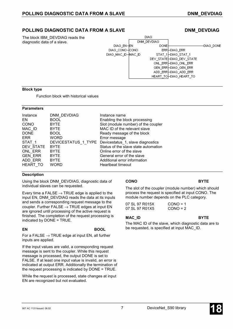
POLLING DIAGNOSTIC DATA FROM A SLAVE DNM_DEVDIAG
907 AC 1131/Issued: 06.02 7 DeviceNet_S90 library 18
POLLING DIAGNOSTIC DATA FROM A SLAVE DNM_DEVDIAGThe block IBM_DEVDIAG reads thediagnostic data of a slave.
Block typeFunction block with historical values
ParametersInstance DNM_DEVDIAG Instance nameEN BOOL Enabling the block processingCONO BYTE Slot (module number) of the couplerMAC_ID BYTE MAC ID of the relevant slaveDONE BOOL Ready message of the blockERR WORD Error messageSTAT_1 DEVICESTATUS_1_TYPE Devicestatus_1, slave diagnosticsDEV_STATE BYTE Status of the slave state automationONL_ERR BYTE Online error of the slaveGEN_ERR BYTE General error of the slaveADD_ERR BYTE Additional error informationHEART_TO WORD Heartbeat timeout
DescriptionUsing the block DNM_DEVDIAG, diagnostic data ofindividual slaves can be requested.
Every time a FALSE → TRUE edge is applied to theinput EN, DNM_DEVDIAG reads the data at its inputsand sends a corresponding request message to thecoupler. Further FALSE → TRUE edges at input ENare ignored until processing of the active request isfinished. The completion of the request processing isindicated by DONE = TRUE.
EN BOOLFor a FALSE → TRUE edge at input EN, all furtherinputs are applied.
If the input values are valid, a corresponding requestmessage is sent to the coupler. While this requestmessage is processed, the output DONE is set toFALSE. If at least one input value is invalid, an error isindicated at output ERR. Additionally the termination ofthe request processing is indicated by DONE = TRUE.
While the request is processed, state changes at inputEN are recognized but not evaluated.
CONO BYTEThe slot of the coupler (module number) which shouldprocess the request is specified at input CONO. Themodule number depends on the PLC category.
07 SL 97 R015X CONO = 107 SL 97 R01X5 CONO = 2
MAC_ID BYTEThe MAC ID of the slave, which diagnostic data are tobe requested, is specified at input MAC_ID.

POLLING DIAGNOSTIC DATA FROM A SLAVE DNM_DEVDIAG
DeviceNet_S90 library 8 907 AC 1131/Issued: 06.0218
DONE BOOLThe output DONE reflects the processing state. If theblock is trigged by a FALSE → TRUE edge at input EN,DONE is set to FALSE. This indicates that the requestis in progress. If processing of the task is completed,DONE is set to TRUE.
The values at the block outputs are only valid ifDONE = TRUE. The diagnostic data are only valid ifalso ERR = 0. If ERR is not equal to 0, an erroroccurred.
ERR WORDERR outputs an error ID if an invalid value was appliedto an input or if an error occurred during requestprocessing. ERR has always to be considered inconjunction with output DONE. The ERR output valueis only valid if DONE = TRUE. The encoding of theerror messages available at ERR applies to allDeviceNet blocks and is explained in section "ERR –Error messages of the DeviceNet blocks".
STAT_1 DEVICESTATUS_1_TYPESTAT_1 outputs different bits as a structure of the typeDEVICESTATUS_1_TYPE which display error states ofthe slave. STAT_1 is only valid if DONE = TRUE andERR = 0.
The format of the structure of the typeDEVICESTATUS_1_TYPE is defined in the DeviceNetlibrary (see description below).
DEV_STATE BYTEDEV_STATE outputs the current state of the coupler'sinternal state machine for the relevant slave. This valueprovides information about the current phase ofcommunication with the device. DEV_STATE is onlyvalid if DONE = TRUE and ERR = 0.
The IDs of the individual states are described on thefollowing pages.
ONL_ERR BYTEONL_ERR outputs a value which describes possibleexisting communication errors between master couplerand slave. ONL_ERR is only valid if DONE = TRUEand ERR = 0.
The error IDs of ONL_ERR correspond to the IDs of theDNM_STAT block output COM_ERR.EVENT. They aredescribed in the table provided in the DNM_STAT blockdescription.
GEN_ERR BYTEGEN_ERR outputs the ID of the last error telegram ofthe slave in accordance to the DeviceNet specification.
GEN_ERR refers only to connection errors(ONL_ERR = 35, see below). Therefore the error ID ofGEN_ERR has always to be considered in conjunctionwith ONL_ERR. GEN_ERR is only valid ifDONE = TRUE, ERR = 0 and ONL_ERR = 35.
The GEN_ERR IDs are described on the followingpages.
ADD_ERR BYTEADD_ERR outputs additional information about theconnection error reported at GEN_ERR. ThereforeADD_ERR has always to be considered in conjunctionwith GEN_ERR. ADD_ERR is only valid ifDONE = TRUE, ERR = 0 and GEN_ERR <> 0.
HEART_TO WORDOutput HEART_TO indicates how often responsemonitoring for this slave was performed.
The DeviceNet bus parameters contain a configurableHeartbeat timer. This timer determines at which timeintervals the master should check the availability of theslaves. HEART_TO contains the number of timeoutsfor the requested slave. Therefore, HEART_TO can beused to make a statement about the quality of theconnection to this slave. The value of this input is onlyvalid for DONE = TRUE and ERR = 0.
Note:The inputs and outputs can neither be duplicated norinverted.

POLLING DIAGNOSTIC DATA FROM A SLAVE DNM_DEVDIAG
907 AC 1131/Issued: 06.02 9 DeviceNet_S90 library 18
Function call in ILCAL DIAG(EN := DIAG_EN,CONO := DIAG_CONO,MAC_ID := DIAG_MAC_ID)
LD DIAG.DONEST DIAG_DONELD DIAG.ERRST DIAG_ERRLD DIAG.STAT_1ST DIAG_STAT_1LD DIAG.DEV_STATEST DIAG_DEV_STATELD DIAG.ONL_ERRST DIAG_ONL_ERRLD DIAG.GEN_ERRST DIAG_GEN_ERRLD DIAG.ADD_ERRST DIAG_ADD_ERRLD DIAG.HEART_TOST DIAG_HEART_TO
Note:In IL, the function call has to be performed in oneline.
Function call in STDIAG(EN := DIAG_EN,CONO := DIAG_CONO,MAC_ID := DIAG_MAC_ID);
DIAG_DONE := DIAG.DONE;DIAG_ERR := DIAG.ERR;DIAG_STAT_1 := DIAG.STAT_1;DIAG_DEV_STATE := DIAG.DEV_STATE;DIAG_ONL_ERR := DIAG.ONL_ERR;DIAG_GEN_ERR := DIAG.GEN_ERR;DIAG_ADD_ERR := DIAG.ADD_ERR;DIAG_HEART_TO := DIAG.HEART_TO;
Devicestatus_1 STAT_1 DEVICESTATUS_1_TYPEThe output STAT_1 of DNM_DEVDIAG displaysdifferent diagnostic bits as a structure of the typeDEVICESTATUS_1_TYPE. Within the DeviceNetlibrary the structure DEVICESTATUS_1_TYPE isdeclared as follows:
TYPE DEVICESTATUS_1_TYPE:STRUCT
NO_RESPONSE: BOOL;reserved1: BOOL;PRM_FAULT: BOOL;CFG_FAULT: BOOL;UCMM_Support: BOOL;reserved2: BOOL;reserved3: BOOL;DEACTIVATED: BOOL;
END_STRUCTEND_TYPE
NO_RESPONSE BOOLIf this bit is set, the slave with the MAC ID specifiedfor the block input MAC_ID does not respond to themaster requests. Normally NO_RESPONSE shouldbe set to FALSE.
reserved1 BOOLThis bit is reserved and currently not used.
PRM_FAULT BOOLThis bit is set, if the write access to at least oneconfigured attribute of the slave was refused. In thiscase a parameterization error occurred.

POLLING DIAGNOSTIC DATA FROM A SLAVE DNM_DEVDIAG
DeviceNet_S90 library 10 907 AC 1131/Issued: 06.0218
CFG_FAULT BOOLThis bit is set, if the actual length of the transmitteddata (actual configuration) differs from the configuredlength (nominal configuration). In this case aconfiguration error occurred.
UCMM_Support BOOLThis bit is reserved and currently not used.
reserved2 BOOLThis bit is reserved and currently not used.
reserved3 BOOLThis bit is reserved and currently not used.
DEACTIVATED BOOLThis bit is set to TRUE, if the slave defined in theconfiguration data of the master is deactivated andnot processed.
DEV_STATEDEV_STATE outputs the current status of themaster's internal state automation of a slave. Thevalue shows the phase of communication betweenmaster and requested slave. The following tabledescribes the possible values of DEV_STATE andthe meaning from the master's point of view.
DEV_STATE Meaning
0 Initial state of the state automation1 Slave inactive and not processed2 Waiting for requests of all slaves to check for duplicate MAC IDs3 Initialization of the internal predefined master slave structures4 Request for allocation of predefined master slave connection sets5 Waiting for slave request after request for allocation of predefined master slave connection sets6 Request for release of predefined master slave connection sets7 Waiting for slave request after request for release of predefined master slave connection sets8 Initialization of internal I/O configuration structures9 Request for allocation of I/O configuration structures10 Waiting for slave request after request for allocation of I/O configuration structures11 Request for release of I/O configuration structures12 Waiting for slave request after request for release of I/O configuration structures13 Request for length of the connection consumed by the slave (output configuration)14 Waiting for slave request after request for length of the connection consumed by the slave15 Comparison of actual output configuration received by the slave with the internal nominal output configuration16 Request for length of the connection produced by the slave (input configuration)17 Waiting for slave request after request for length of the connection produced by the slave18 Comparison of actual input configuration received by the slave with the internal nominal input configuration19 Configuration and registration of I/O connection structures20 Setting the expected packet rate in the slave21 Waiting for slave request after setting the expected packet rate22 Sending the first I/O poll request to the slave23 Waiting for slave request after I/O poll request24 Sending the second I/O poll request to the slave25 Waiting for slave request after I/O poll request26 Sending the third I/O poll request to the slave27 Waiting for slave request after I/O poll request28 Transmission of Heartbeat timeout to slave29 -30 First opening of connectionless communication31 Waiting for slave request after opening the connectionless communication32 Second opening of connectionless communication33 Waiting for slave request after opening the connectionless communication

POLLING DIAGNOSTIC DATA FROM A SLAVE DNM_DEVDIAG
907 AC 1131/Issued: 06.02 11 DeviceNet_S90 library 18
DEV_STATE Meaning
34 Closing the connectionless communication35 Waiting for slave request after closing the connectionless communication36 Enabling of all established connections37 Waiting for slave request after enabling of all established connections38 Opening the connectionless user-specific communication39 Waiting for slave request after opening the connectionless user-specific communication40 Request for allocation of user-specific predefined master slave connections41 Waiting for slave request after request for allocation of user-specific master slave connections42 Closing the connectionless user-specific communication43 Waiting for slave request after request for closing the user-specific master slave connections44 Reading or writing user-specific attribute45 Waiting for request after reading or writing the user-specific attribute46 Sending or waiting for request after fragmentally reading or writing attributes
GEN_ERRThe output GEN_ERR is only valid for the communication error ONL_ERR = 35 (slave rejects requested commandwith error message). In this case, GEN_ERR outputs additional information about the occurred error in accordanceto the DeviceNet specification. The following table shows the possible values and their meanings.
ONL_ERR GEN_ERR Meaning
2 Resource not available8 Service not supported9 Invalid attribute value11 Request mode already active12 Object status conflict14 Attribute cannot be changed15 Privilege violation16 Device status conflict17 Response data too long19 Insufficient data20 Attribute not supported21 Too much data
35:Slave rejects requestedcommand with error message
22 Object does not exist

READING THE DEVICENET COUPLER STATUS DNM_STAT
DeviceNet_S90 library 12 907 AC 1131/Issued: 06.0218
READING THE DEVICENET COUPLER STATUS DNM_STATDNM_STAT outputs the DeviceNet couplerstatus. The outputs provide information aboutthe communication state and error events.
Block typeFunction block without historical values
ParametersInstance DNM_STAT Instance nameEN BOOL Enabling the block processingCONO BYTE Slot (module number) of the couplerERR WORD Error messageSTATE_BITS DNM_STATE_BITS_TYPE Atypical communication statesDNM_STATE BYTE General state of the DeviceNet masterCOM_ERR DNM_COM_ERR_TYPE Communication errorBUS_ERR WORD Number of bus failuresBUS_OFF WORD Number of bus outages
DescriptionThe block DNM_STAT outputs the current DeviceNetcoupler status.
DNM_STAT is active if input EN = TRUE. If the block isactive, always the current values are displayed at theoutputs.
EN BOOLThe block can be activated (EN = TRUE) or deactivated(EN = FALSE) via the input EN. If the block is active,the current values are available at the outputs.
CONO BYTEThe slot of the coupler (module number) whose state isto be read is specified at input CONO. The modulenumber depends on the PLC category.
07 SL 97 R015X CONO = 107 SL 97 R01X5 CONO = 2
ERR INTERR outputs an error ID, if an invalid value was appliedto a block input. ERR has always to be considered inconjunction with the input EN. The ERR output value isonly valid if EN = TRUE. All further outputs are onlyvalid if EN = TRUE and ERR = 0. The encoding of theerror messages available at ERR applies to allDeviceNet blocks and is explained in section "ERR –Error messages of the DeviceNet blocks".
STATE_BITS DNM_STATE_BITS_TYPESTATE_BITS outputs atypical communication states ofthe DeviceNet coupler. STATE_BITS is only valid ifEN = TRUE and ERR = 0.
The format of the structure of the typeDNM_STATE_BITS_TYPE is defined in the DeviceNetlibrary (see description below).
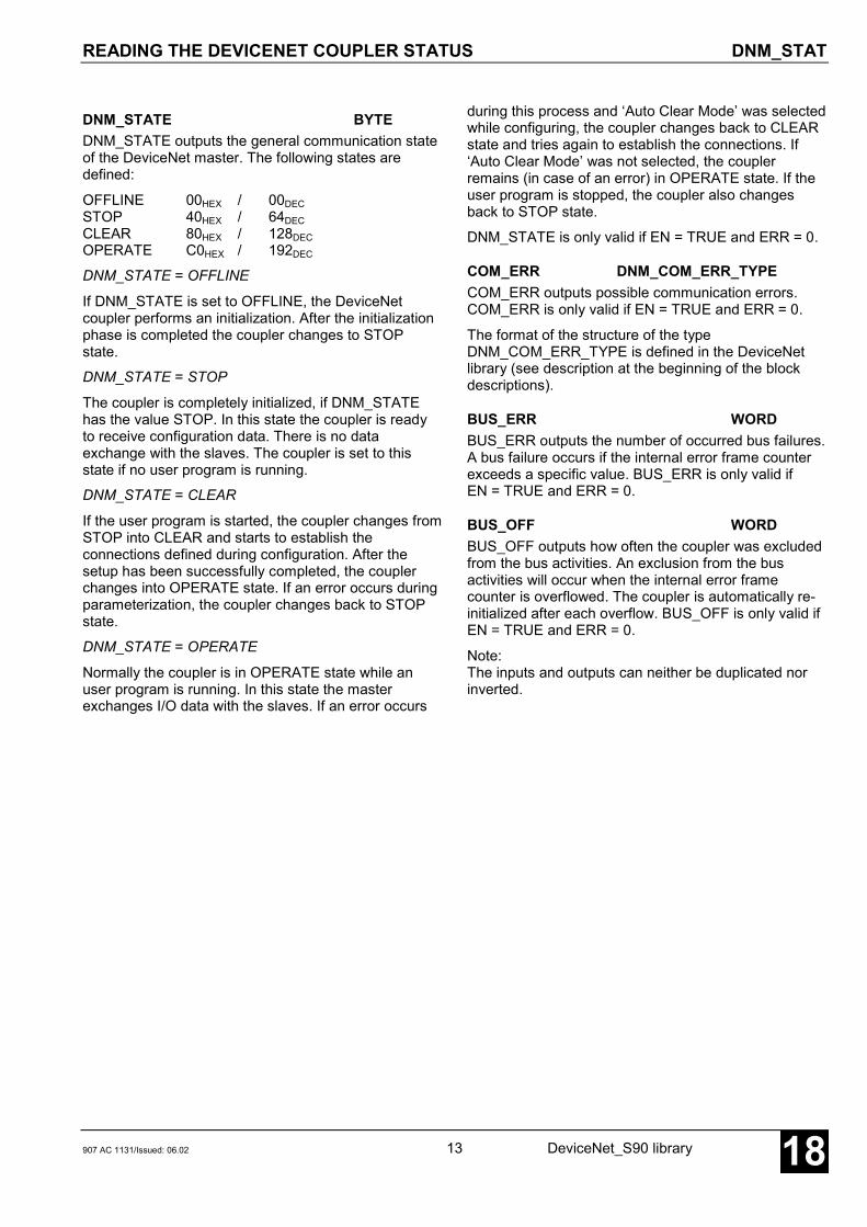
READING THE DEVICENET COUPLER STATUS DNM_STAT
907 AC 1131/Issued: 06.02 13 DeviceNet_S90 library 18
DNM_STATE BYTEDNM_STATE outputs the general communication stateof the DeviceNet master. The following states aredefined:
OFFLINE 00HEX / 00DECSTOP 40HEX / 64DECCLEAR 80HEX / 128DECOPERATE C0HEX / 192DEC
DNM_STATE = OFFLINE
If DNM_STATE is set to OFFLINE, the DeviceNetcoupler performs an initialization. After the initializationphase is completed the coupler changes to STOPstate.
DNM_STATE = STOP
The coupler is completely initialized, if DNM_STATEhas the value STOP. In this state the coupler is readyto receive configuration data. There is no dataexchange with the slaves. The coupler is set to thisstate if no user program is running.
DNM_STATE = CLEAR
If the user program is started, the coupler changes fromSTOP into CLEAR and starts to establish theconnections defined during configuration. After thesetup has been successfully completed, the couplerchanges into OPERATE state. If an error occurs duringparameterization, the coupler changes back to STOPstate.
DNM_STATE = OPERATE
Normally the coupler is in OPERATE state while anuser program is running. In this state the masterexchanges I/O data with the slaves. If an error occurs
during this process and ‘Auto Clear Mode’ was selectedwhile configuring, the coupler changes back to CLEARstate and tries again to establish the connections. If‘Auto Clear Mode’ was not selected, the couplerremains (in case of an error) in OPERATE state. If theuser program is stopped, the coupler also changesback to STOP state.
DNM_STATE is only valid if EN = TRUE and ERR = 0.
COM_ERR DNM_COM_ERR_TYPECOM_ERR outputs possible communication errors.COM_ERR is only valid if EN = TRUE and ERR = 0.
The format of the structure of the typeDNM_COM_ERR_TYPE is defined in the DeviceNetlibrary (see description at the beginning of the blockdescriptions).
BUS_ERR WORDBUS_ERR outputs the number of occurred bus failures.A bus failure occurs if the internal error frame counterexceeds a specific value. BUS_ERR is only valid ifEN = TRUE and ERR = 0.
BUS_OFF WORDBUS_OFF outputs how often the coupler was excludedfrom the bus activities. An exclusion from the busactivities will occur when the internal error framecounter is overflowed. The coupler is automatically re-initialized after each overflow. BUS_OFF is only valid ifEN = TRUE and ERR = 0.
Note:The inputs and outputs can neither be duplicated norinverted.

READING THE DEVICENET COUPLER STATUS DNM_STAT
DeviceNet_S90 library 14 907 AC 1131/Issued: 06.0218
Function call in ILCAL STAT(EN := STAT_EN,CONO := STAT_CONO)LD STAT.ERRST STAT_ERRLD STAT.STATE_BITSST STAT_STATE_BITSLD STAT.DNM_STATEST STAT_DNM_STATELD STAT.COM_ERRST STAT_COM_ERRLD STAT.BUS_ERRST STAT_BUS_ERRLD STAT.BUS_OFFST STAT_BUS_OFF
Note:In IL, the function call has to be performed in oneline.
Function call in STSTAT(EN := STAT_EN,CONO := STAT_CONO);STAT_ERR := STAT.ERR;STAT_STATE_BITS := STAT.STATE_BITS;STAT_DNM_STATE := STAT.DNM_STATE;STAT_COM_ERR := STAT.COM_ERR;STAT_BUS_ERR := STAT.BUS_ERR;STAT_BUS_OFF := STAT.BUS_OFF;
STATE_BITS DNM_STATE_BITS_TYPEThe structure STATE_BITS consists of six booleanvariables which display different communicationstates. Within the DeviceNet library the data typeDNM_STATE_BITS_TYPE is declared as follows:
TYPE DNM_STATE_BITS_TYPE:STRUCT
CTRL: BOOL;AUTO_CLR: BOOL;NO_EXCH: BOOL;FATAL: BOOL;DUP_MAC_CHK: BOOL;DUP_MAC_DET: BOOL;
END_STRUCTEND_TYPE
CTRL BOOLIf this bit is set to TRUE, a parameterization erroroccurred. In normal operation CTRL should beFALSE. If not, the parameter and configuration datahave to be checked.
AUTO_CLR BOOLIf AUTO_CLR is set to TRUE, the coupler hasstopped the data exchange with all slaves due tocommunication errors and has changed back toCLEAR state (see DNM_STATE).
NO_EXCH BOOLThis bit is set to TRUE, if exchanging process datawith one or several slaves is not possible. The errorcause can be found in the configuration data as wellas in the slaves.
FATAL BOOLIf FATAL is set to TRUE, no communication viaDeviceNet is possible due to a fatal bus error (e.g.bus line short circuit). In this case, all bus lines haveto be checked.
DUP_MAC_CHK BOOLIf DUP_MAC_CHK = TRUE, the coupler checks thebus for duplicate MAC IDs. The check is completedwhen the coupler detects other DeviceNet devices onthe bus whose MAC IDs can be checked and noduplicate MAC ID was found. The completion of thecheck is indicated by DUP_MAC_CHK = FALSE.
DUP_MAC_DET BOOLIf DUP_MAC_DET = TRUE, the coupler has detectedanother DeviceNet device with the same MAC ID onthe bus. In this case, the MAC IDs of all devices onthe bus have to be checked.

READING THE DEVICENET COUPLER STATUS DNM_STAT
907 AC 1131/Issued: 06.02 15 DeviceNet_S90 library 18
COM_ERR DNM_COM_ERR_TYPECommunication errors can be located more precisely using COM_ERR. The output COM_ERR is represented as astructure of the type DNM_COM_ERR_TYPE. Within the DeviceNet library this data type is declared as follows:
TYPE COM_ERR_TYPE:STRUCT
ADDRESS: BYTE;EVENT: BYTE;
END_STRUCTEND_TYPE
ADDRESS BYTEIf an error occurs, ADDRESS contains the bus address of the faulty device (0 to 63). If ADDRESS has the value255, the coupler itself causes the error.
EVENT BYTEEVENT displays the error cause. The following tables show the encoding of the various errors.
ADDRESS = 255 Coupler error
EVENT Meaning Error source Cause / Remedy
52 Unknown process data handshakemode Configuration Contact Support
53 Invalid data transmission rate Configuration Check data transmission rate specified inconfiguration data
54 Invalid MAC ID Configuration Check MAC ID specified in configurationdata
57 Duplicate MAC ID found on the bus Configuration /another device
Check MAC ID of all devices specified inconfiguration data
58 No device entry in currentconfiguration data Configuration Error during loading the configuration data;
contact Support
210 No configuration data Configuration /Coupler Load configuration data into coupler
212 Error during reading database Configuration /Coupler Contact Support
220 Watchdog error Control system Contact Support221 No process data handshake Control system Contact Support
ADDRESS = 0..63 Error in device with bus address ADDRESS
EVENT Meaning Error source Cause / Remedy
1 Slave monitoring failed after slavewas already operational Slave Check that the slave is switched on and
runs
30 Slave access timeout Slave Slave is not responding; check baud rateand MAC ID of the slave
32 Slave refuses access with error ID Slave Get slave diagnostics to evaluate the errorID
35 Slave responds with connection errorduring allocation phase Slave Get slave diagnostics to evaluate the
extended error ID

READING THE DEVICENET COUPLER STATUS DNM_STAT
DeviceNet_S90 library 16 907 AC 1131/Issued: 06.0218
EVENT Meaning Error source Cause / Remedy
36
Actual length of produced connection(input data from the master's point ofview) differs from the configuredlength
Slave /Configuration
Get slave diagnostics to determine theactual length
37
Actual length of consumedconnection (output data from themaster's point of view) differs fromthe configured length
Slave /Configuration
Get slave diagnostics to determine theactual length
38 Unknown and unprocessed slaveresponse to service telegram Slave / Coupler Get slave diagnostics to determine the
actual length39 Connection already requested Slave Connection is terminated automatically
40
Number of CAN message data bytesis not 4 when reading the length ofthe produced or consumedconnection
SlaveSlave behavior does not conform to thestandard, communication with slave notpossible
41 Predefined master slave connectionalready exists Slave / Coupler Connection is terminated automatically
42 Slave polling request length differsfrom the produced connection length Slave -
43 Sequence error in slave pollingresponse Slave The first two segments in multiplex transfer
were received
44 Fragmentation error in slave pollingresponse Slave Fragmentation counter differs from the
expected value in multiplex transfer
45 Sequence error in slave pollingresponse Slave Middle or last segment was received prior to
first segment
46Length of slave bit strobe responsediffers from the produced connectionlength
Slave -
47Sequence error in state changeresponse or cyclical response ofslave
Slave The first two segments in multiplex transferwere received
48Fragmentation error in state changeresponse or cyclical response ofslave
Slave Fragmentation counter differs from theexpected value in multiplex transfer
49Sequence error in state changeresponse or cyclical response ofslave
Slave Middle or last segment was received prior tofirst segment
51Length of state change response orcyclical response of the slave differsfrom the produced connection length
Slave -
52 UCMM group not supported Slave Change UCMM group
59 Actual configuration data containduplicate device addresses Configuration Each device must have an unique MAC ID;
edit configuration data
60 Invalid length indicator of a slavedata set Configuration Error loading the configuration data; contact
Support
61 Additional table of predefined masterslave connections has invalid length Configuration Error loading the configuration data; contact
Support
62 Invalid length indicator of the masterslave I/O configuration table Configuration Error loading the configuration data; contact
Support
63Predefined master slave I/Oconfiguration differs from theadditional table
ConfigurationDifferent number of I/O modules andconfigured offset addresses; contactSupport
64 Invalid length indicator of theparameter data set Configuration Too low length indicator; contact Support
65
Number of declared inputs in theadditional table differs from thenumber defined in the I/Oconfiguration
ConfigurationEach I/O configuration entry must haveexactly one assigned entry in the additionaltable; contact Support
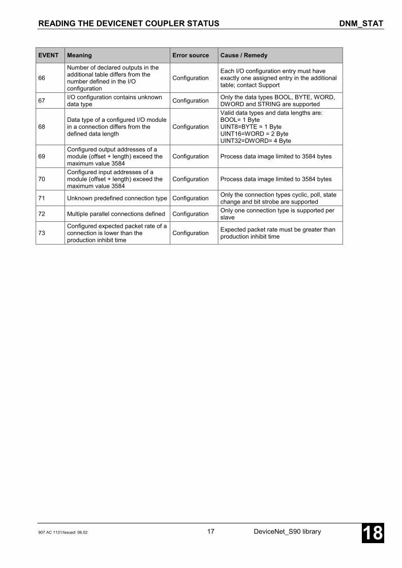
READING THE DEVICENET COUPLER STATUS DNM_STAT
907 AC 1131/Issued: 06.02 17 DeviceNet_S90 library 18
EVENT Meaning Error source Cause / Remedy
66
Number of declared outputs in theadditional table differs from thenumber defined in the I/Oconfiguration
ConfigurationEach I/O configuration entry must haveexactly one assigned entry in the additionaltable; contact Support
67 I/O configuration contains unknowndata type Configuration Only the data types BOOL, BYTE, WORD,
DWORD and STRING are supported
68Data type of a configured I/O modulein a connection differs from thedefined data length
Configuration
Valid data types and data lengths are:BOOL= 1 ByteUINT8=BYTE = 1 ByteUINT16=WORD = 2 ByteUINT32=DWORD= 4 Byte
69Configured output addresses of amodule (offset + length) exceed themaximum value 3584
Configuration Process data image limited to 3584 bytes
70Configured input addresses of amodule (offset + length) exceed themaximum value 3584
Configuration Process data image limited to 3584 bytes
71 Unknown predefined connection type Configuration Only the connection types cyclic, poll, statechange and bit strobe are supported
72 Multiple parallel connections defined Configuration Only one connection type is supported perslave
73Configured expected packet rate of aconnection is lower than theproduction inhibit time
Configuration Expected packet rate must be greater thanproduction inhibit time

READING A STATUS SURVEY OF ALL SLAVES DNM_SYSDIAG
DeviceNet_S90 library 18 907 AC 1131/Issued: 06.0218
READING A STATUS SURVEY OF ALL SLAVES DNM_SYSDIAGThe block DNM_SYSDIAG outputs a bit field asstate survey about all slaves (clients) at outputSLV. Three different surveys can be selected viainput TYP.
Block typeFunction block without historical values
ParametersInstance DNM_SYSDIAG Instance nameEN BOOL Enabling the block processingCONO BYTE Slot (module number) of the couplerTYP BYTE Selection of the survey typeERR WORD Error messageDEV ARRAY [0..63] OF BOOL Status survey of the slaves
DescriptionThe block DNM_SYSDIAG outputs different statussurveys about all slaves. Three survey types can beselected:
– configuration survey– I/O data exchange survey– diagnosis survey
EN BOOLThe block can be activated (EN = TRUE) ordeactivated (EN = FALSE) via the input EN. If theblock is active, the current values are available at theoutputs.
CONO BYTEThe slot of the coupler (module number) whichshould process the request is specified at inputCONO. The module number depends on the PLCcategory.
07 SL 97 R015X CONO = 107 SL 97 R01X5 CONO = 2
TYP BYTEThe input TYP is used to select which status surveyshould be displayed at output DEV.
TYP = 1 configuration survey
Output DEV displays the slaves which weresuccessfully connected to the master. Please notethat the master establishes only a connection tothose slaves which were assigned to the masterwhen defining the configuration data.
TYP = 2 data exchange survey
Output DEV displays the slaves with which themaster exchanges I/O data. The data exchange canonly be performed with slaves which were configuredby the master itself. The data exchange survey canonly be requested, if the coupler is in OPERATEstate.
TYP = 3 diagnosis survey
The output DEV indicates which slaves report adiagnostics. The diagnosis survey can only berequested, if the coupler is in OPERATE state.
ERR WORDERR outputs an error ID, if an invalid value is appliedto an input. ERR has always to be considered inconjunction with the input EN. The ERR output valueis only valid if EN = TRUE. All further outputs are onlyvalid if EN = TRUE and ERR = 0. The encoding ofthe error messages available at ERR applies to allDeviceNet blocks and is explained in section "ERR –Error messages of the DeviceNet blocks".
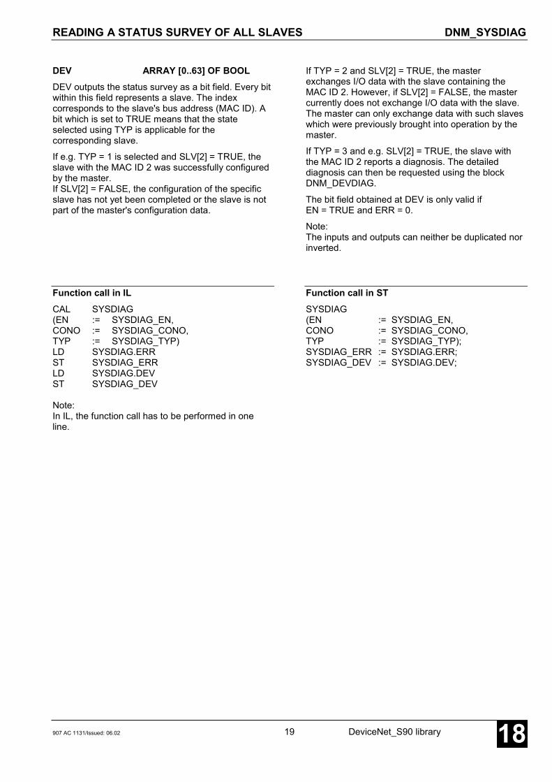
READING A STATUS SURVEY OF ALL SLAVES DNM_SYSDIAG
907 AC 1131/Issued: 06.02 19 DeviceNet_S90 library 18
DEV ARRAY [0..63] OF BOOLDEV outputs the status survey as a bit field. Every bitwithin this field represents a slave. The indexcorresponds to the slave's bus address (MAC ID). Abit which is set to TRUE means that the stateselected using TYP is applicable for thecorresponding slave.
If e.g. TYP = 1 is selected and SLV[2] = TRUE, theslave with the MAC ID 2 was successfully configuredby the master.If SLV[2] = FALSE, the configuration of the specificslave has not yet been completed or the slave is notpart of the master's configuration data.
If TYP = 2 and SLV[2] = TRUE, the masterexchanges I/O data with the slave containing theMAC ID 2. However, if SLV[2] = FALSE, the mastercurrently does not exchange I/O data with the slave.The master can only exchange data with such slaveswhich were previously brought into operation by themaster.
If TYP = 3 and e.g. SLV[2] = TRUE, the slave withthe MAC ID 2 reports a diagnosis. The detaileddiagnosis can then be requested using the blockDNM_DEVDIAG.
The bit field obtained at DEV is only valid ifEN = TRUE and ERR = 0.
Note:The inputs and outputs can neither be duplicated norinverted.
Function call in ILCAL SYSDIAG(EN := SYSDIAG_EN,CONO := SYSDIAG_CONO,TYP := SYSDIAG_TYP)LD SYSDIAG.ERRST SYSDIAG_ERRLD SYSDIAG.DEVST SYSDIAG_DEV
Note:In IL, the function call has to be performed in oneline.
Function call in STSYSDIAG(EN := SYSDIAG_EN,CONO := SYSDIAG_CONO,TYP := SYSDIAG_TYP);SYSDIAG_ERR := SYSDIAG.ERR;SYSDIAG_DEV := SYSDIAG.DEV;

READING AN ATTRIBUTE FROM A SLAVE OBJECT DNM_GET_ATTR
DeviceNet_S90 library 20 907 AC 1131/Issued: 06.0218
READING AN ATTRIBUTE FROM A SLAVE OBJECT DNM_GET_ATTRThe block DNM_GET_ATTRcan be used to readindividual attributes fromobject instances of a slave.
Block typeFunction block with historical values
ParametersInstance DNM_GET_ATTR Instance nameEN BOOL Enabling the block processingCONO BYTE Slot (module number) of the couplerMAC_ID BYTE MAC_ID of the relevant slaveCLASS_ID BYTE Object class ID of the objectINST_ID BYTE Object instance numberATTR_ID BYTE Attribute number within the objectDATA DWORD Address from which on the read data are stored
(via ADR operator)DONE BOOL Ready message of the blockERR WORD Error messageDATA_LEN BYTE Length of read data (byte value)
DescriptionThe block DNM_GET_ATTR can be used to readindividual attributes from slave objects.
Every time a FALSE → TRUE edge is applied to theinput EN, DNM_GET_ATTR reads the data at its inputsand sends a corresponding request message to thecoupler. Further FALSE → TRUE edges at input ENare ignored until processing of the active request isfinished. The completion of the request processing isindicated by DONE = TRUE.
The DeviceNet standard describes an abstract objectmodel (see also system technology of internal couplers– DeviceNet coupler). Here different standard classesare defined which represent a kind of type definitionsfor the objects. In addition further manufacturer-specificclasses can be defined for a DeviceNet module.Objects are instances of the relevant class. Theseobjects contain attributes which can be read using theblock DNM_GET_ATTR.
Some objects must be available in every DeviceNetdevice by default. Normally, these standard objects arenot accessed by the user program during runningoperation, even though this is possible in principle. Theaccesses are usually limited to optional additionalobjects or their attributes. These additional slaveattributes can be displayed in 907 FB 1131 by selecting
Device configuration | Parameter data (see907 FB 1131 documentation). This view displays a listof available attributes for the specific slave. Each entrycontains a sequence number, the object class ID(Class ID), the instance number (Instance ID), thenumber of the individual attribute (Attribute ID), the datatype of the attribute, the valid access types (read/write),an attribute description and the valid limits. For thefunction block DNM_GET_ATTR, this information canbe used to select the required CLASS_ID, INST_ID andATTR_ID. In addition, it can be determined which typethe variable at the block input DATA must have (viaADR operator) in order to be able to store and interpretthe received data.

READING AN ATTRIBUTE FROM A SLAVE OBJECT DNM_GET_ATTR
907 AC 1131/Issued: 06.02 21 DeviceNet_S90 library 18
EN BOOLFor a FALSE → TRUE edge at input EN, all furtherinputs are applied.
If the input values are valid, a corresponding requestmessage is sent to the coupler. While this requestmessage is processed, the output DONE is set toFALSE. If at least one input value is invalid, an error isindicated at output ERR. Additionally the termination ofthe request processing is indicated by DONE = TRUE.
While the request is processed, state changes at inputEN are recognized but not evaluated.
As the block execution requires a bus access, the dataare available in the next cycle at the earliest afteractivating the block.
CONO BYTEThe slot of the coupler (module number) which shouldprocess the request is specified at input CONO. Themodule number depends on the PLC category.
07 SL 97 R015X CONO = 107 SL 97 R01X5 CONO = 2
MAC_ID BYTEAt input MAC_ID, the MAC ID of the slave is specifiedof which an attribute is to be requested.
CLASS_ID BYTEAt input CLASS_ID, the class ID of the object isspecified which contains the attribute to be read(compare to Class entry in Parameter data list in907 FB 1131).
INST_ID BYTEAt input INST_ID, the instance number of the object isspecified which contains the attribute to be read(compare to Inst. entry in Parameter data list in907 FB 1131).
ATTR_ID BYTEAt input ATTR_ID, the number of the attribute isspecified, which should be read within the objectcontaining the attribute (compare to Attr. entry inParameter data list in 907 FB 1131).
DATA DWORDAt input DATA, the address of the variable is specified,to which the received attribute data are to be written(via the ADR operator). For the data format refer to theType entry in the Parameter data list in 907 FB 1131.The received data are only valid if DONE = TRUE,ERR = 0 and DATA_LEN > 0.
DONE BOOLThe output DONE reflects the processing state. If theblock is trigged by a FALSE → TRUE edge at input EN,DONE is set to FALSE. This indicates that the requestis in progress. If processing of the task is completed,DONE is set to TRUE for one cycle period.
The values at the block outputs are only valid ifDONE = TRUE.
ERR WORDERR outputs an error ID if an invalid value was appliedto an input or if an error occurred during requestprocessing. ERR has always to be considered inconjunction with output DONE. The ERR output valueis only valid if DONE = TRUE. The encoding of theerror messages available at ERR applies to allDeviceNet blocks and is explained in section "ERR –Error messages of the DeviceNet blocks".
DATA_LEN BYTEThe length of the received attribute data (byte value)are output at DATA_LEN after the procedure wassuccessfully completed. As the block executionrequires a bus access, the data are available in thenext cycle at the earliest after activating the block. Thevalue of this input is only valid for DONE = TRUE andERR = 0.
Note:The inputs and outputs can neither be duplicated norinverted.

READING AN ATTRIBUTE FROM A SLAVE OBJECT DNM_GET_ATTR
DeviceNet_S90 library 22 907 AC 1131/Issued: 06.0218
Function call in ILLD GET_DATA
ADRST ADR_GET_DATA
CAL GET(EN := GET_EN,CONO := GET_CONO,MAC_ID := GET_MAC_ID,CLASS_ID := GET_CLASS_ID,INST_ID := GET_INST_ID,ATTR_ID := GET_ATTR_ID,DATA := ADR_GET_DATA)
LD GET.DONEST GET_DONELD GET.ERRST GET_ERRLD GET.DATA_LENST GET_DATA_LEN
Note:In IL, the function call has to be performed in oneline.
Function call in STGET(EN := GET_EN,CONO := GET_CONO,MAC_ID := GET_MAC_ID,CLASS_ID := GET_CLASS_ID,INST_ID := GET_INST_ID,ATTR_ID := GET_ATTR_ID,DATA := ADR(GET_DATA));
GET_DONE := GET.DONE;GET_ERR := GET.ERR;GET_DATA_LEN:= GET.DATA_LEN;

RESETTING A SLAVE OBJECT DNM_RESET_OBJ
907 AC 1131/Issued: 06.02 23 DeviceNet_S90 library 18
RESETTING A SLAVE OBJECT DNM_RESET_OBJThe block DNM_RESET_OBJ can be used toreset a slave object.
Block typeFunction block with historical values
ParametersInstance DNM_RESET_OBJ Instance nameEN BOOL Enabling the block processingCONO BYTE Slot (module number) of the couplerMAC_ID BYTE MAC_ID of the relevant slaveCLASS_ID BYTE Object class ID of the objectINST_ID BYTE Object instance numberDONE BOOL Ready message of the blockERR WORD Error message
DescriptionThe block DNM_RESET_OBJ can be used to reset aninstance of a class (object) in a slave.
Every time a FALSE → TRUE edge is applied to theinput EN, DNM_RESET_OBJ reads the data at itsinputs and sends a corresponding request message tothe coupler. Further FALSE → TRUE edges at input ENare ignored until processing of the active request isfinished. The completion of the request processing isindicated by DONE = TRUE.
The DeviceNet standard describes an abstract objectmodel (see also system technology of internal couplers– DeviceNet coupler). Here different standard classesare defined which represent a kind of type definitionsfor the objects. In addition further manufacturer-specificclasses can be defined for a DeviceNet module.Objects are instances of the relevant class. Theseobjects can then be reset using the blockDNM_RESET.
Some objects must be available in every DeviceNetdevice by default. Normally, these standard objects arenot accessed by the user program during runningoperation, even though this is possible in principle. Theaccesses are usually limited to optional additionalobjects or their attributes. These additional slaveobjects/attributes can be displayed in 907 FB 1131 byselecting Device configuration | Parameter data (see907 FB 1131 documentation). This view displays a listof available attributes for the specific slave. Each entrycontains a sequence number, the object class ID(Class ID), the instance number (Instance ID), thenumber of the individual attribute (Attribute ID), the datatype of the attribute, the valid access types (read/write),an attribute description and the valid limits. For thefunction block DNM_RESET_OBJ, this information canbe used to select the required CLASS_ID and INST_ID.

DeviceNet_S90 library 24 907 AC 1131/Issued: 06.0218
EN BOOLFor a FALSE → TRUE edge at input EN, all furtherinputs are applied.
If the input values are valid, a corresponding requestmessage is sent to the coupler. While this requestmessage is processed, the output DONE is set toFALSE. If at least one input value is invalid, an error isindicated at output ERR. Additionally the termination ofthe request processing is indicated by DONE = TRUE.
While the request is processed, state changes at inputEN are recognized but not evaluated.
CONO BYTEThe slot of the coupler (module number) which shouldprocess the request is specified at input CONO. Themodule number depends on the PLC category.
07 SL 97 R015X CONO = 107 SL 97 R01X5 CONO = 2
MAC_ID BYTEAt input MAC_ID, the MAC ID of the slave is specifiedof which an object is to be reset.
CLASS_ID BYTEAt input CLASS_ID, the class ID of the object to bereset is specified (compare to Class entry in Parameterdata list in 907 FB 1131).
INST_ID BYTEAt input INST_ID, the instance number of the object tobe reset is specified (compare to Inst. entry inParameter data list in 907 FB 1131).
DONE BOOLThe output DONE reflects the processing state. If theblock is trigged by a FALSE → TRUE edge at input EN,DONE is set to FALSE. This indicates that the requestis in progress. If processing of the task is completed,DONE is set to TRUE for one cycle period.
The values at the block outputs are only valid ifDONE = TRUE.
ERR WORDERR outputs an error ID if an invalid value was appliedto an input or if an error occurred during requestprocessing. ERR has always to be considered inconjunction with output DONE. The ERR output valueis only valid if DONE = TRUE. The encoding of theerror messages available at ERR applies to allDeviceNet blocks and is explained in section "ERR –Error messages of the DeviceNet blocks".
Note:The inputs and outputs can neither be duplicated norinverted.
Function call in ILCAL RESET(EN := RESET_EN,CONO := RESET_CONO,MAC_ID := RESET_MAC_ID,CLASS_ID := RESET_CLASS_ID),
LD RESET.DONEST RESET_DONELD RESET.ERRST RESET_ERR
Note:In IL, the function call has to be performed in oneline.
Function call in STRESET(EN := RESET_EN,CONO := RESET_CONO,MAC_ID := RESET_MAC_ID,CLASS_ID := RESET_CLASS_ID,INST_ID := RESET_INST_ID);
RESET_DONE := RESET.DONE;RESET_ERR := RESET.ERR;
RESETTING A SLAVE OBJECT DNM_RESET_OBJ
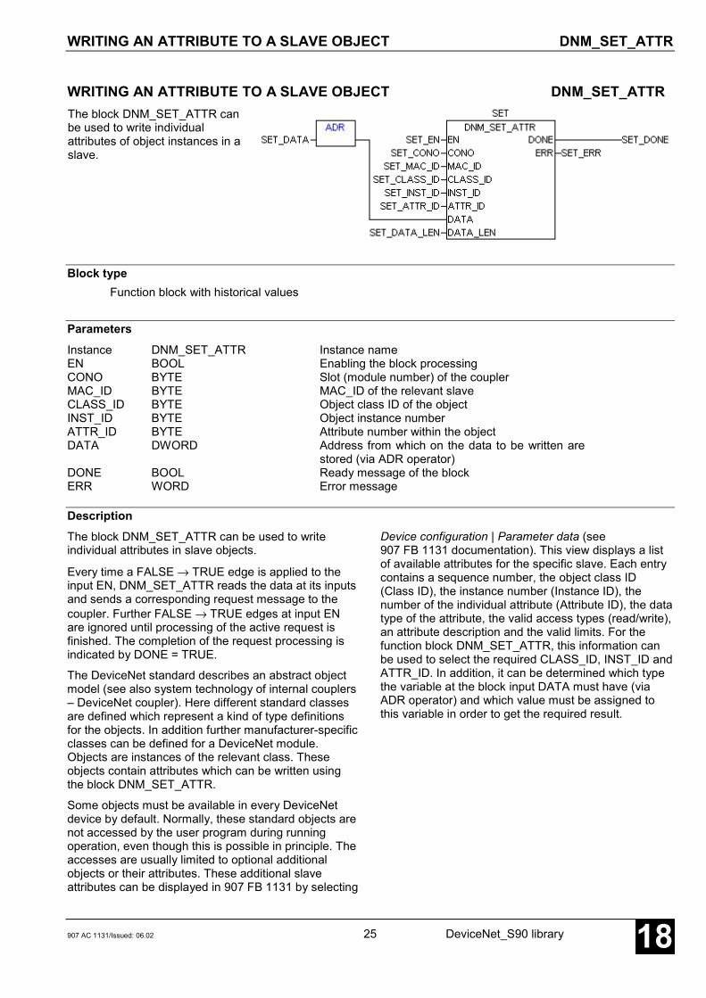
WRITING AN ATTRIBUTE TO A SLAVE OBJECT DNM_SET_ATTR
907 AC 1131/Issued: 06.02 25 DeviceNet_S90 library 18
WRITING AN ATTRIBUTE TO A SLAVE OBJECT DNM_SET_ATTRThe block DNM_SET_ATTR canbe used to write individualattributes of object instances in aslave.
Block typeFunction block with historical values
ParametersInstance DNM_SET_ATTR Instance nameEN BOOL Enabling the block processingCONO BYTE Slot (module number) of the couplerMAC_ID BYTE MAC_ID of the relevant slaveCLASS_ID BYTE Object class ID of the objectINST_ID BYTE Object instance numberATTR_ID BYTE Attribute number within the objectDATA DWORD Address from which on the data to be written are
stored (via ADR operator)DONE BOOL Ready message of the blockERR WORD Error message
DescriptionThe block DNM_SET_ATTR can be used to writeindividual attributes in slave objects.
Every time a FALSE → TRUE edge is applied to theinput EN, DNM_SET_ATTR reads the data at its inputsand sends a corresponding request message to thecoupler. Further FALSE → TRUE edges at input ENare ignored until processing of the active request isfinished. The completion of the request processing isindicated by DONE = TRUE.
The DeviceNet standard describes an abstract objectmodel (see also system technology of internal couplers– DeviceNet coupler). Here different standard classesare defined which represent a kind of type definitionsfor the objects. In addition further manufacturer-specificclasses can be defined for a DeviceNet module.Objects are instances of the relevant class. Theseobjects contain attributes which can be written usingthe block DNM_SET_ATTR.
Some objects must be available in every DeviceNetdevice by default. Normally, these standard objects arenot accessed by the user program during runningoperation, even though this is possible in principle. Theaccesses are usually limited to optional additionalobjects or their attributes. These additional slaveattributes can be displayed in 907 FB 1131 by selecting
Device configuration | Parameter data (see907 FB 1131 documentation). This view displays a listof available attributes for the specific slave. Each entrycontains a sequence number, the object class ID(Class ID), the instance number (Instance ID), thenumber of the individual attribute (Attribute ID), the datatype of the attribute, the valid access types (read/write),an attribute description and the valid limits. For thefunction block DNM_SET_ATTR, this information canbe used to select the required CLASS_ID, INST_ID andATTR_ID. In addition, it can be determined which typethe variable at the block input DATA must have (viaADR operator) and which value must be assigned tothis variable in order to get the required result.

DeviceNet_S90 library 26 907 AC 1131/Issued: 06.0218
EN BOOL
For a FALSE → TRUE edge at input EN, all furtherinputs are applied.
If the input values are valid, a corresponding requestmessage is sent to the coupler. While this requestmessage is processed, the output DONE is set toFALSE. If at least one input value is invalid, an error isindicated at output ERR. Additionally the termination ofthe request processing is indicated by DONE = TRUE.
While the request is processed, state changes at inputEN are recognized but not evaluated.
CONO BYTEThe slot of the coupler (module number) which shouldprocess the request is specified at input CONO. Themodule number depends on the PLC category.
07 SL 97 R015X CONO = 107 SL 97 R01X5 CONO = 2
MAC_ID BYTEAt input MAC_ID, the MAC ID of the slave is specifiedof which an object is to be written.
CLASS_ID BYTEAt input CLASS_ID, the class ID of the object, whichcontains the attribute to be written, is specified(compare to Class entry in Parameter data list in907 FB 1131).
INST_ID BYTEAt input INST_ID, the instance number of the object,which contains the attribute to be written, is specified(compare to Inst. entry in Parameter data list in907 FB 1131).
ATTR_ID BYTEAt input ATTR_ID, the number of the attribute to bewritten within the object, which contains the attribute, isspecified (compare to Attr. entry in Parameter data listin 907 FB 1131).
DATA DWORDAt input DATA, the address of the variable is specifiedwhich contains the attribute data to be transmitted (viaADR operator. For the data format refer to the Typeentry in the Parameter data list in 907 FB 1131.
DATA_LEN BYTEAt input DATA_LEN, the length of the data to betransmitted stored in the variable at address DATA isspecified as a byte value.
DONE BOOLThe output DONE reflects the processing state. If theblock is trigged by a FALSE → TRUE edge at input EN,DONE is set to FALSE. This indicates that the requestis in progress. If processing of the task is completed,DONE is set to TRUE for one cycle period.
The values at the block outputs are only valid ifDONE = TRUE.
ERR WORDERR outputs an error ID if an invalid value was appliedto an input or if an error occurred during requestprocessing. ERR has always to be considered inconjunction with output DONE. The ERR output valueis only valid if DONE = TRUE. The encoding of theerror messages available at ERR applies to allDeviceNet blocks and is explained in section "ERR –Error messages of the DeviceNet blocks".
Note:The inputs and outputs can neither be duplicated norinverted.
WRITING AN ATTRIBUTE TO A SLAVE OBJECT DNM_SET_ATTR
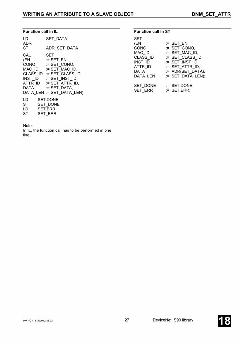
907 AC 1131/Issued: 06.02 27 DeviceNet_S90 library 18
Function call in ILLD SET_DATAADRST ADR_SET_DATA
CAL SET(EN := SET_EN,CONO := SET_CONO,MAC_ID := SET_MAC_ID,CLASS_ID := SET_CLASS_IDINST_ID := SET_INST_ID,ATTR_ID := SET_ATTR_ID,DATA := SET_DATA,DATA_LEN := SET_DATA_LEN)
LD SET.DONEST SET_DONELD SET.ERRST SET_ERR
Note:In IL, the function call has to be performed in oneline.
Function call in STSET(EN := SET_EN,CONO := SET_CONO,MAC_ID := SET_MAC_ID,CLASS_ID := SET_CLASS_ID,INST_ID := SET_INST_ID,ATTR_ID := SET_ATTR_ID,DATA := ADR(SET_DATA),DATA_LEN := SET_DATA_LEN);
SET_DONE := SET.DONE;SET_ERR := SET.ERR;
WRITING AN ATTRIBUTE TO A SLAVE OBJECT DNM_SET_ATTR

DeviceNet_S90 library 28 907 AC 1131/Issued: 06.0218
Glossary
BOOLVariables of the type BOOL can have the values TRUE and FALSE. For this, 8 bit memory space are reserved.
DINTDINT belongs to the integer data types.
The different numerical types are responsible for a different numerical range. For integer data types the followingrange limits are valid:
Type Lower limit Upper limit Memory spaceDINT -2147483648 2147483647 32 Bit
Due to this, it is possible that information are lost during the conversion of greater data types to smaller data types.
DWORDDWORD belongs to the integer data types.
The different numerical types are responsible for a different numerical range. For integer data types the followingrange limits are valid:
Type Lower limit Upper limit Memory spaceDWORD 0 4294967295 32 bit
Due to this, it is possible that information are lost during the conversion of greater data types to smaller data types.
INTINT belongs to the integer data types.
The different numerical types are responsible for a different numerical range. For integer data types the followingrange limits are valid:
Type Lower limit Upper limit Memory spaceINT -32768 32767 16 bit
Due to this, it is possible that information are lost during the conversion of greater data types to smaller data types.
WORDWORD belongs to the integer data types.
The different numerical types are responsible for a different numerical range. For integer data types the followingrange limits are valid:
Type Lower limit Upper limit Memory spaceWORD 0 65535 16 bit
Due to this, it is possible that information are lost during the conversion of greater data types to smaller data types.
STRING
907 AC 1131/Issued: 06.02 29 DeviceNet_S90 library 18
Variables of the type STRING can include any character string. The specified value for the memory spaceallocation in the declaration corresponds to characters and can be defined using parenthesis or brackets. If novalue (1 to 255) is specified, 80 characters are applied by default.
FunctionsFunctions are subroutines which have multiple input parameters and return exactly one result element. Thereturned result can be an elementary or a derived data type. Due to this, a function may also return an array, astructure, an array of structures etc.
For the same input parameters, functions always return the same result (they do not have an internal memory).
Therefore, the following rules can be derived:
• Within functions, global variables can neither be read nor written.• Within functions, it is not allowed to read or write absolute operands.• Within functions, it is not allowed to call function blocks.
Function blocksFunction blocks are subroutines which can have as many inputs, outputs and internal variables as required. Theyare called by a program or by another function block.
As they can be used several times (with different data records), function blocks (code and interface) can beconsidered as type. When assigning an individual data record (declaration) to the function block, a function blockinstance is generated.
In contrast to functions, function blocks can contain statically local data which are saved from one call to the next.This allows for example to realize counters which may not forget their counter value. I.e. function blocks can havean internal memory.
Functions and function blocks differ in two main points:
• A function block has multiple output parameters and a function has a maximum of one output parameter,where the output parameters of functions and function blocks differ syntactically.
• In contrast to a function, a function block can have an internal memory.
1. Function blocks with historical values (memory):
For function blocks with historical values it has to be observed that instance names may not be defined severaltimes if different data sets should be called.
2. Function blocks without historical values (memory):
For function blocks without historical values only one instance has to be defined for the FB type. This instance canbe used for several calls of the FB (also with different I/O values).
The instance name can be defined without any restrictions. The type is preset and identical to the function blockname.
DeviceNet_S90 library 30 907 AC 1131/Issued: 06.0218
Index
CComponents of the DeviceNet library 2
DDeviceNet S90
DEVNET_INFO 5
DNM_DEVDIAG 7
DNM_STAT 12
DNM_SYSDIAG 18
DEVICENET S90
DEVICESTATUS_1_TYPE 9
DNM_COM_ERR_TYPE 15
DNM_GET_ATTR 20
DNM_RESET_OBJ 23
DNM_SET_ATTR 25
DNM_STATE_BITS_TYPE 14
DEVICESTATUS_1_TYPE 9
DEVNET_INFO S90 5
DNM_COM_ERR_TYPE 15
DNM_DEVDIAG S90 7
DNM_GET_ATTR S90 20
DNM_RESET_OBJ S90 23
DNM_SET_ATTR S90 25
DNM_STAT S90 12
DNM_STATE_BITS_TYPE 14
DNM_SYSDIAG S90 18
EError messages of the DeviceNet blocks 3
Software Description Advant Controller 31Intelligent DecentralizedAutomation System
InterbusFunction Block Library90 Series
Interbus90 Series

907 AC 1131/Issued: 06.02 1 Interbus_S90 library 18
Contents
Interbus library 2SPECIAL CHARACTERISTICS IN THE INTERBUS LIBRARY .................................. 2COMPONENTS OF THE INTERBUS LIBRARY .................................. 3Function blocks .................................. 3Data types .................................. 3ERR - ERROR MESSAGES OF THE INTERBUS BLOCKS .................................. 4Errors at block inputs .................................. 4Execution errors, coupler or slave responses .................................. 4
Overview of blocks arranged according to their call names 5READING INFORMATION ABOUT THE INSTALLEDINTERBUS COUPLERS INTERBUS_INFO..... 6POLLING DIAGNOSTIC DATA FROM A SLAVE IBM_SLVDIAG.......... 8READING THE INTERBUS COUPLER STATUS IBM_STAT .............. 13READING A STATUS SURVEY OF ALL SLAVES IBM_SYSDIAG ....... 22READING AN OBJECT DESCRIPTION FROM ASLAVE SUPPORTING PCP IBM_GET_OD ........ 24READING AN OBJECT FROM A SLAVE SUPPORTING PCP IBM_READ ............. 28ENABLING THE READING OF AN OBJECT FROMTHE CONTROL SYSTEM VIA A SLAVE SUPPORTING PCP IBM_READ_EN ...... 31WRITING AN OBJECT TO A SLAVE SUPPORTING PCP IBM_WRITE............ 34ENABLING THE WRITING OF AN OBJECT BY A SLAVESUPPORTING PCP IBM_WRITE_EN..... 37
Glossary 40
Index 42

INTERBUS LIBRARY
Interbus_S90 library 2 907 AC 1131/Issued: 06.0218
Interbus librarySPECIAL CHARACTERISTICS IN THE INTERBUS LIBRARY
Note:
Interbus communication is only performed in RUN mode of the PLC and not in simulation mode.
Prerequisites for use of the library:
The function blocks contained in the Interbus library access to both, the PLC run time system and directly to thecoupler. The required definitions and functions are stored in the internal library Coupler_S90_V41.LIB.
When using the Interbus library Interbus_Master_S90_V43.LIB, it is absolutely essential to insert also thelibrary Coupler_S90_V41.LIB into the project.

COMPONENTS OF THE INTERBUS LIBRARY
907 AC 1131/Issued: 06.02 3 Interbus_S90 library 18
COMPONENTS OF THE INTERBUS LIBRARY
The library contains function blocks which allow an easy handling of the Interbus coupler. Additionally various datatypes are defined in this library. These structures enable a clear presentation of data sets.
Function blocksThe Interbus library contains the following function blocks:
Group GeneralINTERBUS_INFO - Reading information about installed couplers
Group Interbus masterDiagnosis:IBM_SLVDIAG - Polling diagnostic data from a slave
IBM_STAT - Reading the Interbus coupler status
IBM_SYSDIAG - Displaying status information of all slaves
PCP:IBM_GET_OD - Reading object descriptions from a slave supporting PCP
IBM_READ - Writing parameters to a slave supporting PCP
IBM_READ_EN - Enabling the reading of parameters from the control system via a slave supporting PCP
IBM_WRITE - Writing parameters to a slave supporting PCP
IBM_WRITE_EN - Enabling the writing of parameters to the control system via a slave supporting PCP
Detailed information about the various blocks can be found in the following sections.
Data typesThe following data types (structures) are defined in the Interbus library:
IBM_COM_ERR_TYPE - Communication error
IBM_STATE_BITS_TYPE - Bits for coupler state description
IBM_DEVICESTATUS_1_TYPE - Slave diagnostics
IBM_OBJ_DESC_TYPE - Object description
For detailed information about the different data types please refer to the respective description of thecorresponding block.

ERR - ERROR MESSAGES OF THE INTERBUS BLOCKS
Interbus_S90 library 4 907 AC 1131/Issued: 06.0218
ERR - ERROR MESSAGES OF THE INTERBUS BLOCKS
If the output ERR of an Interbus block is unequal to 0, either one of the values at the block inputs is invalid or aninternal error occurred when executing the block. The error cause can be determined with the help of the followingtables.
Errors at block inputs
ERR Meaning
DEC HEX
8193 2001 Invalid value at block input CONO8194 2002 Coupler model in slot CONO does not correspond to the block type8195 2003 No Interbus master coupler in slot CONO8196 2004 Interbus master coupler in slot CONO is not in OPERATE state8197 2005 Invalid status survey type8198 2006 Invalid slave position at block input8201 2009 Invalid communication reference at block input COM_REF8202 200A Invalid data length at block input DATA_LEN or invalid OBJ_NAME
Execution errors, coupler or slave responses
ERR Meaning
DEC HEX
9281 2441 Cannot open PCP connection9283 2443 Too many parallel services via one PCP connection9345 2481 Error in remote station on PCP access (object does not exist or invalid data length)9346 2482 Unknown function on PCP access9347 2483 PCP communication not yet or improperly initialized using this slave9351 2487 PCP access not allowed without configuration data9367 2497 Invalid PCP communication reference9371 249B Invalid PCP service9377 24A1 Invalid slave position at block input

OVERVIEW OF BLOCKS ARRANGED ACCORDING TO THEIR CALL NAMES
907 AC 1131/Issued: 06.02 5 Interbus_S90 library 18
Overview of blocks arranged according to their call names
Character description:
FBmV … Function block with historical values
FBoV … Function block without historical values
F … Function
CE name Type Function Page
IBM_GET_OD FBmV Reading object descriptions from a slave supporting PCP 24
IBM_READ FBmV Reading parameters from a slave supporting PCP 28
IBM_READ_EN FBmV Enabling the reading of parameters from the control system via a slavesupporting PCP
31
IBM_SLVDIAG FBmV Polling diagnostic data from a slave 8
IBM_STAT FBoV Reading the Interbus coupler status 13
IBM_SYSDIAG FBoV Displaying status information of all slaves 22
IBM_WRITE FBmV Writing parameters to a slave supporting PCP 34
IBM_WRITE_EN FBmV Enabling the writing of parameters to the control system via a slavesupporting PCP
37
INTERBUS_INFO FBoV Reading information about the installed couplers 6
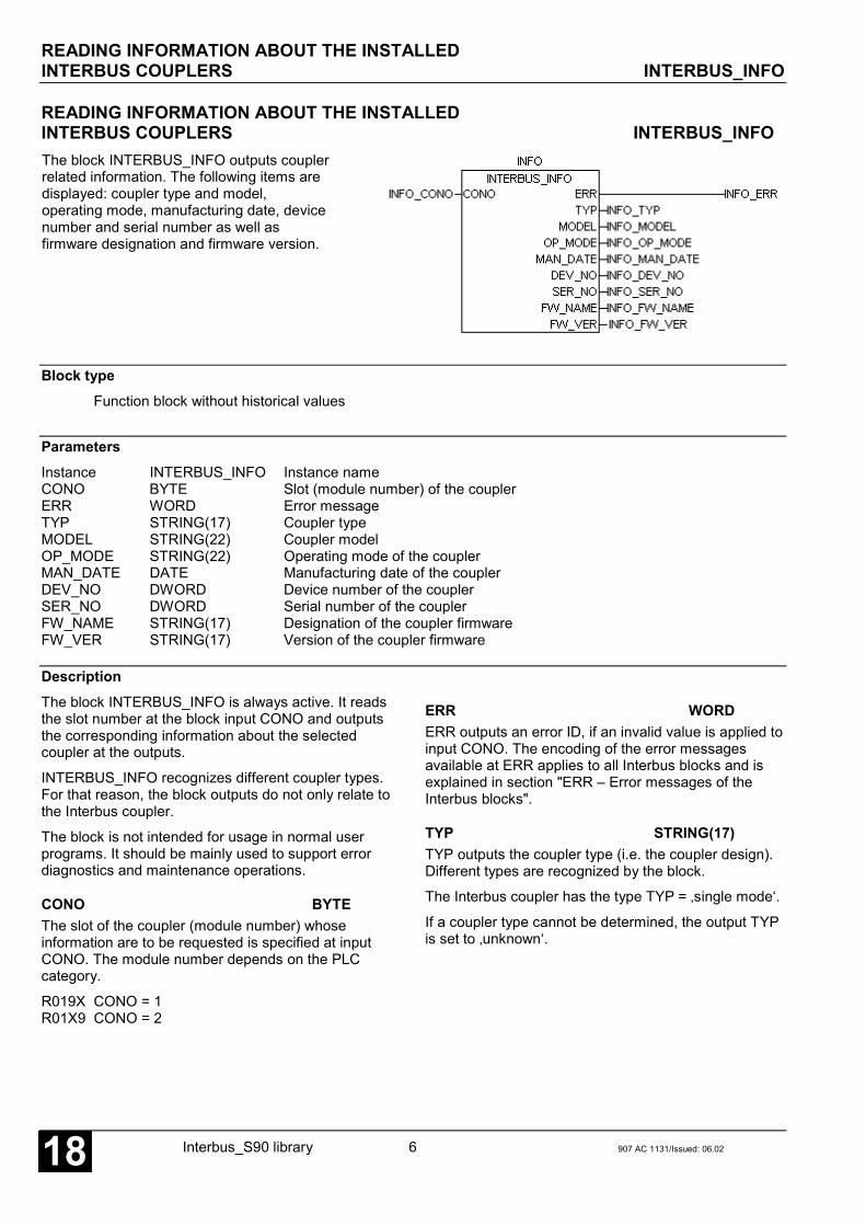
READING INFORMATION ABOUT THE INSTALLEDINTERBUS COUPLERS INTERBUS_INFO
Interbus_S90 library 6 907 AC 1131/Issued: 06.0218
READING INFORMATION ABOUT THE INSTALLEDINTERBUS COUPLERS INTERBUS_INFOThe block INTERBUS_INFO outputs couplerrelated information. The following items aredisplayed: coupler type and model,operating mode, manufacturing date, devicenumber and serial number as well asfirmware designation and firmware version.
Block typeFunction block without historical values
ParametersInstance INTERBUS_INFO Instance nameCONO BYTE Slot (module number) of the couplerERR WORD Error messageTYP STRING(17) Coupler typeMODEL STRING(22) Coupler modelOP_MODE STRING(22) Operating mode of the couplerMAN_DATE DATE Manufacturing date of the couplerDEV_NO DWORD Device number of the couplerSER_NO DWORD Serial number of the couplerFW_NAME STRING(17) Designation of the coupler firmwareFW_VER STRING(17) Version of the coupler firmware
DescriptionThe block INTERBUS_INFO is always active. It readsthe slot number at the block input CONO and outputsthe corresponding information about the selectedcoupler at the outputs.
INTERBUS_INFO recognizes different coupler types.For that reason, the block outputs do not only relate tothe Interbus coupler.
The block is not intended for usage in normal userprograms. It should be mainly used to support errordiagnostics and maintenance operations.
CONO BYTEThe slot of the coupler (module number) whoseinformation are to be requested is specified at inputCONO. The module number depends on the PLCcategory.
R019X CONO = 1R01X9 CONO = 2
ERR WORDERR outputs an error ID, if an invalid value is applied toinput CONO. The encoding of the error messagesavailable at ERR applies to all Interbus blocks and isexplained in section "ERR – Error messages of theInterbus blocks".
TYP STRING(17)TYP outputs the coupler type (i.e. the coupler design).Different types are recognized by the block.
The Interbus coupler has the type TYP = ‚single mode‘.
If a coupler type cannot be determined, the output TYPis set to ‚unknown‘.

READING INFORMATION ABOUT THE INSTALLEDINTERBUS COUPLERS INTERBUS_INFO
907 AC 1131/Issued: 06.02 7 Interbus_S90 library 18
MODEL STRING(22)MODEL outputs the transfer protocol supported by thecoupler as well as the subscriber type.
The model ID of the Interbus coupler isMODEL = ‚Interbus Master‘.
If the block detects an unknown model, MODELoutputs the value ‚unknown‘.
OP_MODE STRING(22)OP_MODE outputs the current coupler operating modesetting. This output is only applicable for couplers withswitchable operating modes.
Therefore, this output is not used for the Interbuscoupler.
MAN_DATE DATEMAN_DATE outputs the manufacturing date of thecoupler. The date is a variable of the data type DATEand has the format D#YYYY-MM-DD. The initial valueis D#2000-01-01.
DEV_NO DWORDDEV_NO outputs the device number of the coupler.
SER_NO DWORDSER_NO outputs the serial number of the coupler.
FW_NAME STRING(17)FW_NAME outputs the name of the coupler firmware.
FW_VER STRING(17)FW_VER outputs the release number (version) andissue date of the coupler firmware. These data arerepresented as a string (e.g. ‚V1.003 15.07.00‘).
Note:The inputs and outputs can neither be duplicated norinverted.
Function call in ILCAL INFO(CONO := INFO_CONO)
LD INFO.ERRST INFO_ERRLD INFO.TYPST INFO_TYPLD INFO.MODELST INFO_MODELLD INFO.OP_MODEST INFO_OP_MODELD INFO.MAN_DATEST INFO_MAN_DATELD INFO.DEV_NOST INFO_DEV_NOLD INFO.SER_NOST INFO_SER_NOLD INFO.FW_NAMEST INFO_FW_NAMELD INFO.FW_VERST INFO_FW_VER
Note:In IL, the function call has to be performed in oneline.
Function call in STINFO(CONO := INFO_CONO);
INFO_ERR := INFO.ERR;INFO_TYP := INFO.TYP;INFO_MODEL := INFO.MODEL;INFO_OP_MODE := INFO.OP_MODE;INFO_MAN_DATE := INFO.MAN_DATE;INFO_DEV_NO := INFO.DEV_NO;INFO_SER_NO := INFO.SER_NO;INFO_FW_NAME := INFO.FW_NAME;INFO_FW_VER := INFO.FW_VER;
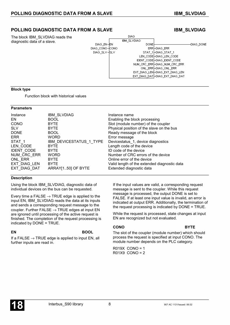
POLLING DIAGNOSTIC DATA FROM A SLAVE IBM_SLVDIAG
Interbus_S90 library 8 907 AC 1131/Issued: 06.0218
POLLING DIAGNOSTIC DATA FROM A SLAVE IBM_SLVDIAGThe block IBM_SLVDIAG reads thediagnostic data of a slave.
Block typeFunction block with historical values
ParametersInstance IBM_SLVDIAG Instance nameEN BOOL Enabling the block processingCONO BYTE Slot (module number) of the couplerSLV BYTE Physical position of the slave on the busDONE BOOL Ready message of the blockERR WORD Error messageSTAT_1 IBM_DEVICESTATUS_1_TYPE Devicestatus_1, device diagnosticsLEN_CODE BYTE Length code of the deviceIDENT_CODE BYTE ID code of the deviceNUM_CRC_ERR WORD Number of CRC errors of the deviceONL_ERR BYTE Online error of the deviceEXT_DIAG_LEN BYTE Valid length of the extended diagnostic dataEXT_DIAG_DAT ARRAY[1..50] OF BYTE Extended diagnostic data
DescriptionUsing the block IBM_SLVDIAG, diagnostic data ofindividual devices on the bus can be requested.
Every time a FALSE → TRUE edge is applied to theinput EN, IBM_SLVDIAG reads the data at its inputsand sends a corresponding request message to thecoupler. Further FALSE → TRUE edges at input ENare ignored until processing of the active request isfinished. The completion of the request processing isindicated by DONE = TRUE.
EN BOOLIf a FALSE → TRUE edge is applied to input EN, allfurther inputs are read in.
If the input values are valid, a corresponding requestmessage is sent to the coupler. While this requestmessage is processed, the output DONE is set toFALSE. If at least one input value is invalid, an error isindicated at output ERR. Additionally, the termination ofthe request processing is indicated by DONE = TRUE.
While the request is processed, state changes at inputEN are recognized but not evaluated.
CONO BYTEThe slot of the coupler (module number) which shouldprocess the request is specified at input CONO. Themodule number depends on the PLC category.
R019X CONO = 1R01X9 CONO = 2

POLLING DIAGNOSTIC DATA FROM A SLAVE IBM_SLVDIAG
907 AC 1131/Issued: 06.02 9 Interbus_S90 library 18
SLV BYTEThe physical position of the device in the Interbusnetwork for which diagnostic data are to be requestedis specified at input SLV. Valid values are 1 to 128.
Numbering of the devices starts with the deviceimmediately connected to the master. This device getsthe number 1. All further devices connected to theremote bus are numbered continuously. When usingbus terminals the numbering is first continued in thelower-level segment. The following figure shows thecounting mode when determining the physical positionof a device in an Interbus network.
DONE BOOLThe output DONE reflects the processing state. If theblock is trigged by a FALSE → TRUE edge at input EN,DONE is set to FALSE. This indicates that the requestis in progress. If processing of the task is completed,DONE is set to TRUE.
The values at the block outputs are only valid ifDONE = TRUE. The diagnostic data are only valid ifalso ERR = 0. If ERR is not equal to 0, an erroroccurred.
ERR WORDERR outputs an error ID if an invalid value was appliedto an input or if an error occurred during requestprocessing. ERR has always to be considered inconjunction with output DONE. The ERR output valueis only valid if DONE = TRUE. The encoding of theerror messages available at ERR applies to all Interbusblocks and is explained in section "ERR – Errormessages of the Interbus blocks".
STAT_1 IBM_DEVICESTATUS_1_TYPESTAT_1 outputs different bits as a structure of the typeIBM_DEVICESTATUS_1_TYPE which display errorstates of the slave. STAT_1 is only valid ifDONE = TRUE and ERR = 0.
The format of the structure of the typeIBM_DEVICESTATUS_1_TYPE is defined in theInterbus library (see description below).
LEN_CODE BYTELEN_CODE outputs the actual length code of thedevice. This value is directly read from the concerningdevice. In case of configuration errors, the comparisonof this actual length code with the corresponding setlength code specified in the configuration data can beused to determine the error source. LEN_CODE is onlyvalid if DONE = TRUE and ERR = 0.
IDENT_CODE BYTEIDENT_CODE outputs the actual ID code of the device.This value is directly read from the concerning device.In case of configuration errors, the comparison of thisactual ID code with the corresponding set ID codespecified in the configuration data can be used todetermine the error source. IDENT_CODE is only validif DONE = TRUE and ERR = 0.
NUM_CRC_ERR WORDNUM_CRC_ERR outputs the number of occurredchecksum errors. An ascending counting valueindicates electrical or electromagnetic interference inthe environment of the concerning device.NUM_CRC_ERR is only valid if DONE = TRUE andERR = 0.

POLLING DIAGNOSTIC DATA FROM A SLAVE IBM_SLVDIAG
Interbus_S90 library 10 907 AC 1131/Issued: 06.0218
ONL_ERR BYTEONL_ERR outputs a value which describes possibleexisting communication errors between master couplerand slave. ONL_ERR is only valid if DONE = TRUEand ERR = 0.
The error IDs of ONL_ERR correspond to the IDs of theIBM_STAT block output COM_ERR.EVENT. They aredescribed in the table provided in the IBM_STAT blockdescription.
EXT_DIAG_LEN BYTEEXT_DIAG_LEN outputs the length or the number ofvalid entries of the extended diagnostic data inEXT_DIAG_DAT. If EXT_DIAG_LEN = 0, no extendeddiagnostic data for the corresponding device areavailable. Otherwise, EXT_DIAG_LEN contains theindex of the last valid BYTE of the ARRAYEXT_DIAG_DAT. EXT_DIAG_LEN is only valid ifDONE = TRUE and ERR = 0.
EXT_DIAG_DAT ARRAY [1..50] OF BYTEEXT_DIAG_DAT outputs, if available, additionalextended diagnostic information about the relevantdevice (see EXT_DIAG_LEN). This information isstored internally in the coupler and reset after eachdiagnostic request of the specific slave.EXT_DIAG_DAT is only valid if DONE = TRUE andERR = 0.
The EXT_DIAG_DAT IDs are described in the followingsections.
Note:The inputs and outputs can neither be duplicated norinverted.
Function call in ILCAL DIAG(EN := DIAG_EN,CONO := DIAG_CONO,SLV := DIAG_SLV)
LD DIAG.DONEST DIAG_DONELD DIAG.ERRST DIAG_ERRLD DIAG.STAT_1ST DIAG_STAT_1LD DIAG.LEN_CODEST DIAG_LEN_CODELD DIAG.IDENT_CODEST DIAG_IDENT_CODELD DIAG.NUM_CRCST DIAG_NUM_CRCLD DIAG.ONL_ERRST DIAG_ONL_ERRLD DIAG.EXT_DIAG_LENST DIAG_EXT_DIAG_LENLD DIAG.EXT_DIAG_DATST DIAG_EXT_DIAG_DAT
Note:In IL, the function call has to be performed in oneline.
Function call in STDIAG(EN := DIAG_EN,CONO := DIAG_CONO,SLV := DIAG_SLV);
DIAG_DONE := DIAG.DONE;DIAG_ERR := DIAG.ERR;DIAG_STAT_1 := DIAG.STAT_1;DIAG_LEN_CODE := DIAG.LEN_CODE;DIAG_IDENT_CODE := DIAG.IDENT_CODE;DIAG_NUM_CRC_ERR := DIAG.NUM_CRC_ERR;DIAG_ONL_ERR := DIAG.ONL_ERR;DIAG_EXT_DIAG_LEN := DIAG.EXT_DIAG_LEN;DIAG_EXT_DIAG_DAT := DIAG.EXT_DIAG_DAT;

POLLING DIAGNOSTIC DATA FROM A SLAVE IBM_SLVDIAG
907 AC 1131/Issued: 06.02 11 Interbus_S90 library 18
Devicestatus_1 STAT_1 IBM_DEVICESTATUS_1_TYPEThe output STAT_1 of IBM_DEVDIAG displaysdifferent diagnostic bits as a structure of the typeIBM_DEVICESTATUS_1_TYPE. Within the Interbuslibrary the structure IBM_DEVICESTATUS_1_TYPEis declared as follows:
TYPE IBM_DEVICESTATUS_1_TYPE:STRUCT
NO_RESPONSE: BOOL;BUFFER_OVFL: BOOL;PERIPHERAL: BOOL;CFG_FAULT: BOOL;RECONFIG: BOOL;INTERFACE_2: BOOL;INTERFACE_1: BOOL;DEACTIVATED: BOOL;
END_STRUCTEND_TYPE
NO_RESPONSE BOOLIf this bit is set, the slave with the position specifiedfor the block input SLV does not respond to therequests of the master or is not available.Normally NO_RESPONSE should be set to FALSE.
BUFFER_OVFL BOOLIf this bit is set, more diagnostic data concerning therelevant device are available than data can bebuffered.
PERIPHERAL BOOLIf this bit is set, the slave has detected a powersupply failure for the process inputs or a short circuitin at least one process input.
CFG_FAULT BOOLThis bit is set, if the actual length and/or ID code(actual configuration) of the device differs from theconfigured length and/or ID code (nominalconfiguration). In this case a configuration erroroccurred.
RECONFIG BOOLIf this bit is set, the slave reports a reconfigurationrequest. Bus terminals often provide a reconfigurationbutton which is accessible from the outside. Pressingthis button on the site (e.g. because an additionalslave module was installed), this is reported byRECONFIG = TRUE. As a result the master shouldbe reconfigured in order to enable it to detect theplanned system expansion.
INTERFACE_2 BOOLIf this bit is set, the concerning device has switchedoff its outgoing bus interface 2 due to a failure.
INTERFACE_1 BOOLIf this bit is set, the concerning device has switchedoff its outgoing bus interface 1 due to a failure. Thisinterface is only available for devices with busterminal property. It describes the interface to thelower-level segment.
DEACTIVATED BOOLThis bit is set to TRUE, if the device is defined in theconfiguration data of the master, but it is notactivated. Therefore the concerning device is notprocessed. To include the device into processing, ithas to be activated in the configuration data and thedata has to be reloaded into the master.
EXT_DIAG_DAT
The output EXT_DIAG_DAT consists of an ARRAYwith a minimum size of 50 BYTE. This ARRAYprovides, if available, additional diagnosticinformation concerning the relevant device.
The maximum number of extended diagnostic data is50 BYTE. The actual amount of currently availabledata may change. As a result, the current valid lengthis output at EXT_DIAG_LEN. If for exampleEXT_DIAG_DAT is an ARRAY [1..50] OF BYTE andEXT_DIAG_LEN = 7, the entries with the indexes 1to 7 contain the currently available diagnosticinformation. If EXT_DIAG_LEN = 0, no extendedinformation are available.

POLLING DIAGNOSTIC DATA FROM A SLAVE IBM_SLVDIAG
Interbus_S90 library 12 907 AC 1131/Issued: 06.0218
Each BYTE of the ARRAY EXT_DIAG_DAT containsindependent information. If more information areavailable at the same time, these are listed insequence. Therefore, EXT_DIAG_DAT has to beevaluated byte wise. The following table shows thepossible error descriptions for
EXT_DIAG_DAT and provides appropriate actions fortheir remedy.
EXT_DIAG_DAT[i] Meaning Error source Action/Remedy
0 No error - -
30 Device was not availableduring last network scan cycle
Device /Configuration
Check if configured device actually exists andInterbus is properly cabled
31 Device contains other ID code thanconfigured
Device /Configuration
Check if configured ID code (EDS file) or ID codereported by the device is valid
32 Device contains other length code thanconfigured
Device /Configuration
Check if configured length code (EDS file) orlength code reported by the device is valid
33 Device has detected an unconfigured deviceat the outgoing bus interface 1
Device /Configuration
Determine the actual configuration of thedevice(s) and insert the device(s) intoconfiguration
34 Device has detected an unconfigured deviceat the outgoing bus interface 2
Device /Configuration
Determine the actual configuration of thedevice(s) and insert the device(s) intoconfiguration
35 Device was not availableduring last network scan cycle
Device /Configuration
Check the complete segment, where the deviceis located, for configuration errors
36 Device reports error at process input DeviceCheck if supply voltage of external peripheraldevices is properly connected or a short circuit ina process input exists
37 Device reports reconfiguration request Device Review configuration data and retransmit thedata to the coupler
38 Device detected CRC error during datatransmission Device Check the environment of the device for electrical
or electromagnetic interference39 - - -
40 Device has damaged outgoing businterface 1 (bus terminal only) Device Check the interface for correct cabling
41 Device has damaged outgoing businterface 2 Device Check the interface for correct cabling
42 Device has not properly reported ID andlength code during last network scan cycle Network Check the environment of the device for electrical
or electromagnetic interference
43Device not available during runningoperation due to disconnection of theInterbus connection
NetworkCheck the Interbus cabling between theconcerning device and the devices locatedphysically before
44 Connection to this device due to adisconnection in a local bus terminal lost
Local busterminal
Check the Interbus cabling between theconcerning device and the devices locatedphysically before
45During the last network scan cycle inrunning operation this was the last physicaldevice to which a connection could be made
NetworkCheck the Interbus cabling between theconcerning device and the device locatedphysically behind
46As the control system was temporarily in theSTOP state, also the communication to thisdevice was stopped temporarily
Operation
No error. This is only a note.This status message is generated only once aftera RUN -> STOP -> RUN procedure of the controlsystem

READING THE INTERBUS COUPLER STATUS IBM_STAT
907 AC 1131/Issued: 06.02 13 Interbus_S90 library 18
READING THE INTERBUS COUPLER STATUS IBM_STATIBM_STAT outputs the status of an Interbuscoupler. The outputs provide information aboutthe communication state and error events.
Block typeFunction block without historical values
ParametersInstance IBM_STAT Instance nameEN BOOL Enabling the block processingCONO BYTE Slot (module number) of the couplerERR WORD Error messageSTATE_BITS IBM_STATE_BITS_TYPE Atypical communication statesIBM_STATE BYTE General state of the Interbus masterCOM_ERR IBM_COM_ERR_TYPE Communication errorDEF_DATA_CYC WORD Number of bad data cyclesNETWORK_SCANS WORD Number of required network scansPD_CYC DWORD Number of performed process data cyclesDEF_PD_CYC DWORD Number of bad process data cyclesDIAG_CYC DWORD Number of performed diagnostic cyclesDEV_DIAGS DWORD Number of reported device diagnostics
DescriptionThe block IBM_STAT outputs the current Interbuscoupler status.
IBM_STAT is active if input EN = TRUE. If the block isactive, always the current values are displayed at theoutputs.
EN BOOLThe block can be activated (EN = TRUE) or deactivated(EN = FALSE) via the input EN. If the block is active,the current values are available at the outputs.
CONO BYTEThe slot of the coupler (module number) whose state isto be read is specified at input CONO. The modulenumber depends on the PLC category.
R019X CONO = 1R01X9 CONO = 2
ERR INTERR outputs an error ID, if an invalid value was appliedto a block input. ERR has always to be considered inconjunction with the input EN. The ERR output value isonly valid if EN = TRUE. All further outputs are onlyvalid if EN = TRUE and ERR = 0. The encoding of theerror messages available at ERR applies to all Interbusblocks and is explained in section "ERR – Errormessages of the Interbus blocks".
STATE_BITS IBM_STATE_BITS_TYPESTATE_BITS outputs atypical communication states ofthe Interbus coupler. STATE_BITS is only valid ifEN = TRUE and ERR = 0.
The format of the structure of the typeIBM_STATE_BITS_TYPE is defined in the Interbuslibrary (see description below).

READING THE INTERBUS COUPLER STATUS IBM_STAT
Interbus_S90 library 14 907 AC 1131/Issued: 06.0218
IBM_STATE BYTEIBM_STAT outputs the general communication stateof the Interbus master. The following states aredefined:
OFFLINE 00HEX / 00DECSTOP 40HEX / 64DECCLEAR 80HEX / 128DECOPERATE C0HEX / 192DEC
IBM_STATE = OFFLINE
If IBM_STATE is set to OFFLINE, the Interbuscoupler performs an initialization. After theinitialization phase is completed the coupler changesto STOP state.
IBM_STATE = STOP
If IBM_STATE has the value STOP, the coupler iscompletely initialized. In this state the coupler isready to receive configuration data. There is no dataexchange with the slaves. The coupler is set to thisstate if no user program is running.
IBM_STATE = CLEAR
If the user program is started, the coupler changesfrom STOP into CLEAR and starts to establish theconnections defined during configuration. After thesetup has been successfully completed, the couplerchanges into OPERATE state. If an error occursduring parameterization, the coupler changes back toSTOP state.
IBM_STATE = OPERATE
Normally the coupler is in OPERATE state while anuser program is running. In this state the masterexchanges I/O data with the slaves. If an error occursduring this process, the coupler behaves as specifiedfor the configured bus parameters, i.e. it remains inthe OPERATE state or changes back to CLEAR stateand retries, if necessary, to run the system. If theuser program is stopped, the coupler also changesback to STOP state.
IBM_STATE is only valid if EN = TRUE and ERR = 0.
COM_ERR IBM_COM_ERR_TYPEThe output COM_ERR displays possiblecommunication errors. COM_ERR is only valid ifEN = TRUE and ERR = 0.
The format of the structure of the typeIBM_COMM_ERR_TYPE is defined in the Interbuslibrary and is described below together with thepossible errors.
DEF_DATA_CYC WORDDEF_DATA_CYC outputs the total number of busmalfunctions occurred since system configuration orstartup. Bad process data cycles and failures(diagnostic) reported by the slaves are counted. If thevalue of DEF_DATA_CYC increases, this indicatesEMC interference in the environment of the Interbusnetwork, an incorrect bus cabling or a bad powersupply of the devices.
DEF_DATA_CYC is only valid if EN = TRUE andERR = 0.
NETWORK_SCANS WORDNETWORK_SCANS outputs the total number ofrequired re-initializations of the Interbus networksince system configuration or startup. Such re-initializations result from bus errors. If a fatal buserror occurs, the master resets the Interbus networkand searches the network for the fault location. Thisprocedure is called 'scan'. Depending on theconfiguration, the master either stops the completeInterbus communication or restarts thecommunication. If communication is restarted, onlythose devices are included which were detectedduring the last scan and which are error free.
NETWORK_SCANS is only valid if EN = TRUE andERR = 0.
PD_CYC DWORDPD_CYC outputs the total number of process datacycles performed since system configuration orstartup.
PD_CYC is only valid if EN = TRUE and ERR = 0.
DEF_PD_CYC DWORDDEF_PD_CYC outputs the total number of failedprocess data cycles detected since systemconfiguration or startup.
DEF_PD_CYC is only valid if EN = TRUE andERR = 0.
DIAG_CYC DWORDDIAG_CYC outputs the total number of diagnosticcycles performed since system configuration orstartup.
DIAG_CYC is only valid if EN = TRUE and ERR = 0.

READING THE INTERBUS COUPLER STATUS IBM_STAT
907 AC 1131/Issued: 06.02 15 Interbus_S90 library 18
DEV_DIAGS DWORDDEV_DIAGS outputs the total number of diagnosticevents reported by all slaves.
DEV_DIAGS is only valid if EN = TRUE andERR = 0.
Note:The inputs and outputs can neither be duplicated norinverted.
Function call in ILCAL STAT(EN := STAT_EN,CONO := STAT_CONO)
LD STAT.ERRST STAT_ERRLD STAT.STATE_BITSST STAT_STATE_BITSLD STAT.IBM_STATEST STAT_IBM_STATELD STAT.COM_ERRST STAT_COM_ERRLD STAT.DEF_DATA_CYCST STAT_DEF_DATA_CYCLD STAT.NETWORK_SCANSST STAT_NETWORK_SCANSLD STAT.PD_CYCST STAT_PD_CYCLD STAT.DEF_PD_CYCST STAT_DEF_PD_CYCLD STAT.DIAG_CYCST STAT_DIAG_CYCLD STAT.DEV_DIAGSST STAT_DEV_DIAGS
Note:In IL, the function call has to be performed in one line.
Function call in STSTAT(EN := STAT_EN,CONO := STAT_CONO);
STAT_ERR := STAT.ERR;STAT_STATE_BITS := STAT.STATE_BITS;STAT_IBM_STATE := STAT.IBM_STATE;STAT_COM_ERR := STAT.COM_ERR;STAT_DEF_DATA_CYC :=
STAT.DEF_DATA_CYCSTAT_NETWORK_SCANS :=
STAT.NETWORK_SCANS;STAT_PD_CYC := STAT.PD_CYC;STAT_DEF_PD_CYC := STAT.DEF_PD_CYC;STAT_DIAG_CYC := STAT.DIAG_CYC;STAT_DEV_DIAGS := STAT.DEV_DIAGS;

READING THE INTERBUS COUPLER STATUS IBM_STAT
Interbus_S90 library 16 907 AC 1131/Issued: 06.0218
STATE_BITS IBM_STATE_BITS_TYPEThe structure STATE_BITS consists of sevenboolean variables which display differentcommunication states. Within the Interbus library thedata type IBM_STATE_BITS_TYPE is declared asfollows:
TYPE IBM_STATE_BITS_TYPE:STRUCT
CTRL: BOOL;AUTO_CLR: BOOL;NO_EXCH: BOOL;PERIPHERAL: BOOL;EVENT: BOOL;INTERFACE_1: BOOL;INTERFACE_2: BOOL;
END_STRUCTEND_TYPE
CTRL BOOLIf this bit is set to TRUE, a parameterization error or afatal runtime error occurred. In normal operationCTRL should be FALSE. If not, the parameter andconfiguration data have to be checked.
AUTO_CLR BOOLIf AUTO_CLR is set to TRUE, the coupler hasstopped the data exchange with all slaves due tocommunication errors and has changed back toCLEAR state (see IBM_STATE). This will cause alloutputs to change to the secure zero state. Thebehavior of the master is determined duringconfiguration (bus parameters). Either thecommunication is reactivated by stopping andrestarting the control system or a cold or warm startis required.
NO_EXCH BOOLThis bit is set to TRUE, if exchanging process datawith at least one slave is not possible. The errorcause can be found in the configuration data as wellas in the slave itself. A more detailed diagnostic canbe obtained by evaluating COM_ERR.
PERIPHERAL BOOLIf at least one device reports a peripheral error, thebit PERIPHERAL is set to TRUE. A peripheral errorcan be a short circuit in a local process output of aslave or a bad or missing power supply for theprocess inputs. The faulty device can be locatedusing COM_ERR.ADDRESS. If the error occurssimultaneously in several devices,COM_ERR.ADDRESS contains the position of thedevice which is physically located next to the master.
EVENT BOOLIf EVENT is set to TRUE, at least one bad processdata cycle occurred or the Interbus network wasreset, scanned and reinitialized due to a modificationof the network configuration (see DEF_DATA_CYCand NETWORK_SCANS). This bit can only be resetby a warm or cold start of the control system.
INTERFACE_1 BOOLIf INTERFACE_1 = TRUE, the outgoing businterface 1 of a device (bus terminal) was switchedoff due to an error. The faulty device can be locatedusing COM_ERR.ADDRESS. If the error occurssimultaneously in several devices,COM_ERR.ADDRESS contains the position of thedevice which is physically located next to the master.
INTERFACE_2 BOOLIf INTERFACE_2 = TRUE, the outgoing businterface 2 of a device (bus terminal or slave) wasswitched off due to an error. The faulty device can belocated using COM_ERR.ADDRESS. If the erroroccurs simultaneously in several devices,COM_ERR.ADDRESS contains the position of thedevice which is physically located next to the master.

READING THE INTERBUS COUPLER STATUS IBM_STAT
907 AC 1131/Issued: 06.02 17 Interbus_S90 library 18
COM_ERR IBM_COM_ERR_TYPECommunication errors can be located more preciselyusing COM_ERR. The output COM_ERR isrepresented as a structure of the typeIBM_COM_ERR_TYPE. Within the Interbus librarythis data type is declared as follows:
TYPE COM_ERR_TYPE:STRUCT
ADDRESS: BYTE;EVENT: BYTE;
END_STRUCTEND_TYPE
ADDRESS BYTEIn case of an error, ADDRESS contains the busaddress of the faulty device (0 to 128). If ADDRESShas the value 255, the coupler itself causes the error.
EVENT BYTEEVENT displays the error cause. The following tablesshow the encoding of the various errors.
ADDRESS = 255 Coupler error
EVENT Meaning Error source Cause / Remedy
52 Unknown process data handshakemode
Configuration Contact Support
56 No configuration data Configuration /Coupler
Load configuration data into coupler
57 Defective Interbus Controller Coupler Contact Support; coupler replacement 101 A configured length or ID code differs
from the real network configurationConfiguration /Network
Check the ID and length codes of alldevices
102 Too many devices connected Network Reduce the number of devices on the bus103 Network configuration has changed
during ID cycleNetwork Wait until the coupler automatically performs
the next ID cycle104 Network startup failed Network Contact Support105 ID cycle interrupt due to non
detectable network errors which arecaused by the installation of devicesor a faulty slave
Network Wait until the coupler automatically performsthe next ID cycle
106 Device, which was already detectedduring the previous ID cycle, ismissing in the following cycle
Network Wait until the coupler automatically performsthe next ID cycle
107 Network configuration was changedin running operation, an alreadyoperating device does no longerrespond
Network Check the network; wait until the couplerautomatically performs the next ID cycle
108 No connection to Interbus network Network Check the connection between master andfirst slave
220 Watchdog error Control system Contact Support221 No process data handshake Control system Contact Support224 Error communicating with Interbus
ControllerCoupler Contact Support

READING THE INTERBUS COUPLER STATUS IBM_STAT
Interbus_S90 library 18 907 AC 1131/Issued: 06.0218
ADDRESS = 1..128 Error in device with physical position ADDRESS
EVENT Meaning Error source Cause / Remedy
Device was not available during lastnetwork scan cycle
Slave /Configuration
Check the configuration data and Interbuscabling
30
A configured device could not be found in the Interbus network. But no fundamental error could bedetermined in the bus cabling. Therefore, this can be an error in the master configuration or theconcerning module is not located at the configured position within the Interbus ring.Compare the configured system description to the real configuration of the Interbus network.If no differences can be found, check the connection between the faulty module and the modulelocated before in the Interbus ring.If the connection is also OK, monitor the module's LED ‚RC‘ or ‚CC‘. If this LED does not lightstatically, a cabling error occurred. Please note that an Interbus cable must have a bridge betweentwo pins of the male connector at the outgoing bus interface of the module. The interface is onlyactivated, if this bridge is available. Verify that the bridge at the outgoing interface of the precedingmodule is properly wired.Device reports another ID code thanspecified in the configuration data
Slave /Configuration
Compare the configured ID code to the realID code of the device
31
The concerning device was found during the last network cycle but has reported another ID codethan defined in the configuration data of the master. The ID code determines the device functionalityand defines the device class and the I/O data supported by the device. If the retransmitted ID codediffers from the configured ID, the master does not include the device into process data exchange.Compare both ID codes and refer to the manufacturer's documentation or the label on the device forthe valid code. If necessary, edit the EDS file of this device and reload the configuration into themaster.Device reports another length codethan specified in the configurationdata
Slave /Configuration
Compare the configured length code to thereal length code of the device
32
The relevant device was found during the last network cycle but has reported another length codethan contained in the configuration data of the master. The length code describes the number andlength of I/O data of a device. If the retransmitted length code differs from the configured length, themaster does not include the device into process data exchange.Compare both length codes and refer to the manufacturer's documentation or the label on the devicefor the valid code. If necessary, edit the EDS file of this device and reload the configuration into themaster.Unconfigured device found atoutgoing bus interface 1
Slave /Configuration
Check the actual configuration of theunconfigured device; change configurationdata
33
A communication error occurred. The following configured device is located in another bus segmentlevel than the device configured at this position. This can have two reasons.Either the bus segment level of the following device is configured improperly or the master has reallydetected at least one unconfigured device at the outgoing bus interface 1 of this device. Only deviceswith bus terminal properties are equipped with this outgoing bus interface 1.Compare the configuration data to the real Interbus system configuration. Especially pay attention tomissing devices and segment levels. Reedit the configuration and reload it into the master, if needed.

READING THE INTERBUS COUPLER STATUS IBM_STAT
907 AC 1131/Issued: 06.02 19 Interbus_S90 library 18
EVENT Meaning Error source Cause / Remedy
Unconfigured device found atoutgoing bus interface 2
Slave /Configuration
Check the actual configuration of theunconfigured device; change configurationdata
34
A communication error occurred. The following configured device is located in another bus segmentlevel than the device configured at this position. This can have two reasons.Either the bus segment level of the following device is configured improperly or the master has reallydetected at least one unconfigured device at the outgoing bus interface 2 of this device. Both(installation) remote bus and local bus devices contain this outgoing bus interface 2. If a local bussegment causes the error, the complete segment is switched off. If the error occurs in the remotebus, all devices located before the faulty device remain running and all following devices will bedeactivated.Compare the configuration data to the real Interbus system configuration. Especially pay attention tomissing devices and segment levels. Reedit the configuration and reload it into the master, if needed.Peripheral error Slave Check the power supply of the module's
process inputs; check the process outputsfor short circuit
36
If a slave reports a peripheral error, it has detected either an error in the power supply for the processinputs or a short circuit at the local inputs or outputs. The module can be operated in principle and itis still processed.As this error message is generated vendor specific, no detailed statement can be made concerningthe error source.First, you should check the module's LEDs. The LED ‚Us‘ indicates if power supply is available. To beable to determine if an error occurred at the local I/Os, the input and output LEDs or a specific I/Oerror LED should be monitored depending on the module's functionality.Reconfiguration request Slave Master reset; update configuration data
accordingly37
Devices with bus terminal functionality usually have a reconfiguration button accessible from theoutside. If this button is pressed, the relevant module sends a corresponding message to the master.This message causes the master to reset the Interbus system and to reconfigure the system. As thisprocedure cannot be performed automatically, a warm or cold start has to be performed manually.The configuration data have to be edited and reloaded, if needed.Outgoing bus interface 1 (busterminal) failed
Device Check the cabling of the relevant businterface
40
The outgoing (installation) remote bus or local bus interface of the bus terminal has caused a timeouterror during a network scan cycle used to search for devices which are actually available in thesegment.Typically, this error occurs when connecting an Interbus cable to the interface to which no furtherdevices are connected. Check the connection between the interface and the following module.If no error can be found, check the LEDs of the connected modules.In case of a local bus terminal, the LEDs ‚RC‘ or ‚CC‘ of all modules should light continuously. TheseLEDs indicate a generally working connection to the master. If the LED of one module does not lightcontinuously, the Interbus connection between the relevant device and the preceding device has tobe checked.If all LEDs are on, the connections in transmitting direction (from the master's point of view) are error-free. In this case, probably one of the modules itself is faulty and retransmits no data or the receptioninterface (towards the master) of one module is electrically defective.In case of an (installation) remote bus terminal, the ‚RC‘ or ‚CC‘ LED of the directly following moduleof this terminal should light continuously. If not, the Interbus connection between the two devices isinterrupted. The error can be caused by both the outgoing bus interface of the terminal and theincoming interface of the directly following module. First, the Interbus connection between these twodevices has to be checked.If the LED lights, the error can be caused by the module's return connection to the master or by theincoming interface of the terminal. In this case, the devices should be replaced individually to locatethe error.

READING THE INTERBUS COUPLER STATUS IBM_STAT
Interbus_S90 library 20 907 AC 1131/Issued: 06.0218
EVENT Meaning Error source Cause / Remedy
Outgoing bus interface 2 (busterminal or slave) failed
Device Check the cabling of the relevant businterface
41
The outgoing interface of the device has caused a timeout error during a network scan cycle used tosearch for actually available devices.Typically, this error occurs when connecting an Interbus cable to the interface to which no furtherdevices are connected. Check the connection between the interface and the following module.If no error can be detected, check the ‚RC‘ or ‚CC‘ LED of the directly following module. If the LEDdoes not light continuously, the Interbus transmitting line between the two devices is interrupted.Check the Interbus connection between the two devices.If the LED lights, either the following module is faulty and does not transmit data or the incominginterface of the device itself is electrically defective.Device did not properly respond tothe request for an ID code or lengthcode during the last network scan
Network Check the environment of the device forpossible EMC interference sources
42
If errors are reported for process data cycles in running operation, a network scan cycle isautomatically performed. The master then compares the ID and length codes retransmitted by thedevices with the corresponding codes defined in the configuration data. If the IDs differ, this error isgenerated.Typically, this error can only occur, if one device is first switched off and then switched on again andthe ID code „µP not ready“ = 0x0038 is reported during this time. As a result, this error eventindicates that a slave was switched off in the mean time. Check the bus cable shielding and the slavegrounding and ensure that no temporary outages or overvoltages occur for the power supply.
46 Device is no longer operated by thecoupler
Coupler Coupler has stopped communicating withthis device

READING THE INTERBUS COUPLER STATUS IBM_STAT
907 AC 1131/Issued: 06.02 21 Interbus_S90 library 18
Configuration errors (70 – 92)
EVENT Meaning Error source Cause / Remedy
70 Duplicate address configured Configuration Contact Support71 Incorrect length of device data set Configuration Contact Support72 Incorrect length of process data
configurationConfiguration Contact Support
73 Incorrect length of extended table Configuration Contact Support74 Incorrect length of PCP data Configuration Contact Support75 Inconsistency of the complete data
setConfiguration Contact Support
76 Inconsistency of extended table Configuration Contact Support77 Maximum allowed offset for the
process output data exceededConfiguration Contact Support
78 Maximum allowed offset for theprocess input data exceeded
Configuration Contact Support
79 Maximum allowed offset address> 255 exceeded
Configuration Contact Support
80 Number of modules and offsetsinconsistent
Configuration Contact Support
81 Number of output modules andoffsets differs
Configuration Contact Support
82 Number of input modules and offsetsdiffers
Configuration Contact Support
83 Actual output data length differs fromconfigured length
Configuration Contact Support
84 Actual input data length differs fromconfigured length
Configuration Contact Support
85 Output data overlapping Control system Contact Support86 Input data overlapping Configuration Contact Support87 Output device has also inputs Configuration Contact Support88 Input device has also outputs Configuration Contact Support89 Output device has inputs Configuration Contact Support90 Input device has outputs Configuration Contact Support91 Device with incorrect segment level
configuredConfiguration Contact Support
92 Configured ID code not supported bythe coupler
Configuration Contact Support
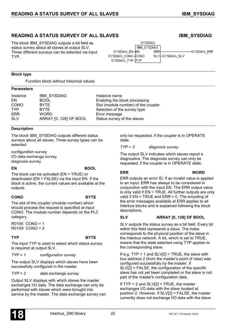
READING A STATUS SURVEY OF ALL SLAVES IBM_SYSDIAG
Interbus_S90 library 22 907 AC 1131/Issued: 06.0218
READING A STATUS SURVEY OF ALL SLAVES IBM_SYSDIAGThe block IBM_SYSDIAG outputs a bit field asstatus survey about all slaves at output SLV.Three different surveys can be selected via inputTYP.
Block typeFunction block without historical values
ParametersInstance IBM_SYSDIAG Instance nameEN BOOL Enabling the block processingCONO BYTE Slot (module number) of the couplerTYP BYTE Selection of the survey typeERR WORD Error messageSLV ARRAY [0..128] OF BOOL Status survey of the slaves
DescriptionThe block IBM_SYSDIAG outputs different statussurveys about all slaves. Three survey types can beselected:
configuration surveyI/O data exchange surveydiagnosis survey
EN BOOLThe block can be activated (EN = TRUE) ordeactivated (EN = FALSE) via the input EN. If theblock is active, the current values are available at theoutputs.
CONO BYTEThe slot of the coupler (module number) whichshould process the request is specified at inputCONO. The module number depends on the PLCcategory.
R019X CONO = 1R01X9 CONO = 2
TYP BYTEThe input TYP is used to select which status surveyis required at output SLV.
TYP = 1 configuration survey
The output SLV displays which slaves have beensuccessfully configured in the master.
TYP = 2 data exchange survey
Output SLV displays with which slaves the masterexchanges I/O data. The data exchange can only beperformed with slaves which were brought intoservice by the master. The data exchange survey can
only be requested, if the coupler is in OPERATEstate.
TYP = 3 diagnosis survey
The output SLV indicates which slaves report adiagnostics. The diagnosis survey can only berequested, if the coupler is in OPERATE state.
ERR WORDERR outputs an error ID, if an invalid value is appliedto an input. ERR has always to be considered inconjunction with the input EN. The ERR output valueis only valid if EN = TRUE. All further outputs are onlyvalid if EN = TRUE and ERR = 0. The encoding ofthe error messages available at ERR applies to allInterbus blocks and is explained following the blockdescriptions.
SLV ARRAY [0..128] OF BOOLSLV outputs the status survey as a bit field. Every bitwithin this field represents a slave. The indexcorresponds to the physical position of the slave inthe Interbus network. A bit, which is set to TRUE,means that the state selected using TYP applies tothe corresponding slave.
If e.g. TYP = 1 and SLV[2] = TRUE, the slave withbus address 2 (from the master's point of view) wasconfigured successfully by the master. IfSLV[2] = FALSE, the configuration of the specificslave has not yet been completed or the slave is notpart of the master's configuration data.
If TYP = 2 and SLV[2] = TRUE, the masterexchanges I/O data with the slave located atposition 2. However, if SLV[2] = FALSE, the mastercurrently does not exchange I/O data with the slave.

READING A STATUS SURVEY OF ALL SLAVES IBM_SYSDIAG
907 AC 1131/Issued: 06.02 23 Interbus_S90 library 18
The master can only exchange data with such slaveswhich were previously brought into operation by themaster.
If TYP = 3 and e.g. SLV[2] = TRUE, the slave atposition 2 reports a diagnosis. The detailed diagnosiscan then be requested using the blockIBM_SLVDIAG.
The bit field obtained at SLV is only valid ifEN = TRUE and ERR = 0.
Note:The inputs and outputs can neither be duplicated norinverted.
Function call in ILCAL SYSDIAG(EN := SYSDIAG_EN,CONO := SYSDIAG_CONO,TYP := SYSDIAG_TYP)
LD SYSDIAG.ERRST SYSDIAG_ERRLD SYSDIAG.SLVST SYSDIAG_SLV
Note:In IL, the function call has to be performed in oneline.
Function call in STSYSDIAG(EN := SYSDIAG_EN,CONO := SYSDIAG_CONO,TYP := SYSDIAG_TYP);
SYSDIAG_ERR := SYSDIAG.ERR;SYSDIAG_SLV := SYSDIAG.SLV;

READING AN OBJECT DESCRIPTION FROM ASLAVE SUPPORTING PCP IBM_GET_OD
Interbus_S90 library 24 907 AC 1131/Issued: 06.0218
READING AN OBJECT DESCRIPTION FROM ASLAVE SUPPORTING PCP IBM_GET_ODThe block IBM_GET_OD can be usedto get a description of an object froma slave supporting PCP. The object ofinterest can be accessed either usingthe object index or the symbolicname. IBM_GET_OD does notprovide the value of an object.
Block typeFunction block with historical values
ParametersInstance IBM_GET_OD Instance nameEN BOOL Enabling the block processingCONO BYTE Slot (module number) of the couplerCOM_REF BYTE Communication referenceBY_NAME BOOL Request selection via object name or index nameOBJ_IDX WORD Object indexOBJ_NAME STRING(22) Object nameDONE BOOL Ready message of the blockERR WORD Error messageOBJ_DESC IBM_OBJ_DESC_TYPE Object information
DescriptionThe block IBM_GET_OD can be used to getinformation about a PCP object from a slave. Theobject of interest can be accessed either using theobject index or the symbolic name. IBM_GET_OD doesnot provide the value of an object (see blockIBM_READ). The corresponding CommunicationReference (CR) as well as an Object Directory (OD) ofthe slave must have been previously defined whenconfiguring (see 907 FB 1131 documentation).
Every time a FALSE → TRUE edge is applied to theinput EN, IBM_GET_OD reads the data at its inputsand sends a corresponding request message to thecoupler. Further FALSE → TRUE edges at input ENare ignored until processing of the active request isfinished. The completion of the request processing isindicated by DONE = TRUE.
EN BOOLFor a FALSE → TRUE edge at input EN, all furtherinputs are applied.
If the input values are valid, a corresponding requestmessage is sent to the coupler. While this requestmessage is processed, the output DONE is set toFALSE. If at least one input value is invalid, an error isindicated at output ERR. Additionally the termination ofthe request processing is indicated by DONE = TRUE.
While the request is processed, state changes at inputEN are recognized but not evaluated.
CONO BYTEThe slot of the coupler (module number) which shouldprocess the request is specified at input CONO. Themodule number depends on the PLC category.
R019X CONO = 1R01X9 CONO = 2

READING AN OBJECT DESCRIPTION FROM ASLAVE SUPPORTING PCP IBM_GET_OD
907 AC 1131/Issued: 06.02 25 Interbus_S90 library 18
COM_REF BYTEThe Communication Reference (CR) number isspecified at input COM_REF. Valid values are 2 to 63.Using the Communication Reference, the device isindirectly selected which data are to be read. For thecorresponding number refer to the CommunicationRelationship List (CRL) in the 907 FB 1131configuration data.
BY_NAME BYTEThe input BY_NAME is used to select how the object isaccessed whose description is required.
With BY_NAME = FALSE the object is specified usingthe object index applied to the input OBJ_IDX, i.e. thedescription of the object which index is applied to theinput OBJ_IDX is read.
If BY_NAME = TRUE, the object is specified using thesymbolic name applied to the input OBJ_NAME, i.e. thedescription of the object which name is applied to theinput OBJ_NAME is read.
For the configured objects and the correspondingindices (Obj.Idx.) or names (descriptions) refer to theObject Directory (OD) of the specific device in the907 FB 1131 configuration data.
OBJ_IDX WORDThe index of the object, whose description is to berequested, is specified at input OBJ_IDX. Generally, allvalues (0 – 65535) are valid for OBJ_IDX, but theaccess to unconfigured objects causes an error. Forthe configured objects and the corresponding indices(Obj.Idx.) refer to the Object Directory (OD) of thespecific device in the 907 FB 1131 configuration data.
If BY_NAME = FALSE a valid value must be applied toOBJ_IDX. If BY_NAME = TRUE, OBJ_IDX is ignoredand the input OBJ_NAME is evaluated.
OBJ_NAME STRING(22)The symbolic name of the object, whose description isto be requested, is specified at input OBJ_NAME.Generally, every STRING with up to 10 characters isallowed for OBJ_NAME (last character is string endcharacter), but the access to unconfigured objectscauses an error. For the configured objects and thecorresponding names (description) refer to the ObjectDirectory (OD) of the specific device in the907 FB 1131 configuration data.
If BY_NAME = TRUE a valid value must be applied toOBJ_NAME. If BY_NAME = FALSE, OBJ_NAME isignored and the input OBJ_IDX is evaluated.
DONE BOOLThe output DONE reflects the processing state. If theblock is trigged by a FALSE → TRUE edge at input EN,DONE is set to FALSE. This indicates that the requestis in progress. If processing of the task is completed,DONE is set to TRUE for one cycle period.
The values at the block outputs are only valid ifDONE = TRUE. The object description OBJ_DESC isonly valid if also ERR = 0. If ERR is not equal to 0, anerror occurred.
ERR WORDERR outputs an error ID if an invalid value was appliedto an input or if an error occurred during requestprocessing. ERR has always to be considered inconjunction with output DONE. The ERR output valueis only valid if DONE = TRUE. The encoding of theerror messages available at ERR applies to Interbusblocks and is explained after the block descriptions.

READING AN OBJECT DESCRIPTION FROM ASLAVE SUPPORTING PCP IBM_GET_OD
Interbus_S90 library 26 907 AC 1131/Issued: 06.0218
OBJ_DESC IBM_OBJ_DESC_TYPEOBJ_DESC outputs the description of the requestedobject. OBJ_DESC is only valid if DONE = TRUE andERR = 0.
The format of the structure of the typeIBM_OBJ_DESC_TYPE is defined in the Interbuslibrary as follows.
TYPE IBM_OBJ_DESC_TYPE:STRUCT
OBJ_INDEX: WORD;OBJ_CODE: BYTE;NUM_OBJ_ELEM: BYTE;INDEX_OF_TYPE: WORD;OBJ_LENGTH: BYTE;
END_STRUCTEND_TYPE
OBJ_INDEX WORDOBJ_INDEX provides the index of the requestedobject. In case of an object description request usingthe object index (BY_NAME = FALSE), this valueprovides no further information. In this case, it containsthe value of the input OBJ_IDX after an error-freeexecution. If the object description request is doneusing the symbolic name (BY_NAME = TRUE),OBJ_INDEX outputs the index of the object with thesymbolic name OBJ_NAME.
OBJ_CODE BYTEOBJ_CODE provides the type of the requested object.There are 3 object types:
OBJ_CODE Object type
Dec Hex 907 AC 1131 Interbus
7 07 Single variable Simple Variable
8 08 ARRAY Array
9 09 STRUCT Record
If OBJ_CODE = 7, the object is a single variable of thedata type specified for INDEX_OF_TYPE.OBJ_CODE = 8 specifies an object organized asARRAY with NUM_OBJ_ELEM elements of the datatype specified for INDEX_OF_TYPE. OBJ_CODE = 9describes an object which represents a structure(STRUCT) combined using several variables ofdifferent data types. Different standardized structuretypes are defined in the Interbus profiles (seeINDEX_OF_TYPE).
NUM_OBJ_ELEM BYTENUM_OBJ_ELEM contains the number of elements ofan object of the type ARRAY (OBJ_CODE = 8).
INDEX_OF_TYPE BYTEINDEX_OF_TYPE provides the type of data containedin the requested object. The following list shows the IDsof the defined standard data types. Additionally, thedata types ‚Process data description‘ and ‚Ramp‘,described in the Interbus profile 22 (DRIVECOM), arelisted. For the structure of these data types as well asthe IDs and structures of the additional types refer tothe corresponding profiles or the manufacturerdescriptions for the particular device.
INDEX_OF_TYPE
Data type
Dec Hex 907 AC 1131 Interbus
Lengthin Byte
1 01 BOOL Boolean 12 02 SINT Integer8 13 03 INT Integer16 24 04 DINT Integer32 4
5 05 USINT, BYTE Unsigned8 16 06 UINT, WORD Unsigned16 27 07 UDINT, DWORD Unsigned32 48 08 REAL Floating point 49 09 STRING Visible string n10 0A ARRAY [] OF BYTE Octet string n11 0B - Date 7
12 0C TIME_OF_DAY Time-Of-Day 413 0D (TIME) Time-
Difference4
14 0E (ARRAY [ ] OF BYTE) Bit string n...32 20 - Process data
description-
33 21 - Ramp -
If the relevant object is a single variable(OBJ_CODE = 7), the complete object consists of onesingle variable of a listed data type. If an objectconsists of an ARRAY of variables (OBJ_CODE = 8),INDEX_OF_TYPE specifies the data type of eachindividual element of the ARRAY.
Here it has to be observed that for combined data typesalso ARRAYs of structures (e.g.INDEX_OF_TYPE = 32) or two-dimensional ARRAYs(e.g. INDEX_OF_TYPE = 10) can exist.
Additionally, it has to be considered that for someInterbus data types no corresponding data types(really) exist in 907 AC 1131.

READING AN OBJECT DESCRIPTION FROM ASLAVE SUPPORTING PCP IBM_GET_OD
907 AC 1131/Issued: 06.02 27 Interbus_S90 library 18
OBJ_LENGTH BYTEIf the relevant object is a single variable(OBJ_CODE = 7) or a structure (OBJ_CODE = 9),OBJ_LENGTH provides the length or structure of thevariables and therefore the length of the completeobject as a BYTE value. If the object is organized asARRAY (OBJ_CODE = 8), OBJ_LENGTH specifies the
length of each individual element of the ARRAY as aBYTE value.
Note:The inputs and outputs can neither be duplicated norinverted.
Function call in ILCAL GET_OD(EN := GET_OD_EN,CONO := GET_OD_CONO,COM_REF := GET_OD_MAC_ID,BY_NAME := GET_OD_CLASS_ID,OBJ_IDX := GET_OD_INST_ID,OBJ_NAME := GET_OD_ATTR_ID)
LD GET_OD.DONEST GET_OD_DONELD GET_OD.ERRST GET_OD_ERRLD GET_OD.OBJ_DESCST GET_OD_OBJ_DESC
Note:In IL, the function call has to be performed in oneline.
Function call in STGET_OD(EN := GET_OD_EN,CONO := GET_OD_CONO,COM_REF := GET_OD_COM_REF,BY_NAME := GET_OD_BY_NAME,OBJ_IDX := GET_OD_OBJ_IDX,OBJ_NAME := GET_OD_OBJ_NAME)
GET_OD_DONE := GET_OD.DONE;GET_OD_ERR := GET_OD.ERR;GET_OD_OBJ_DESC := GET_OD.OBJ_DESC;
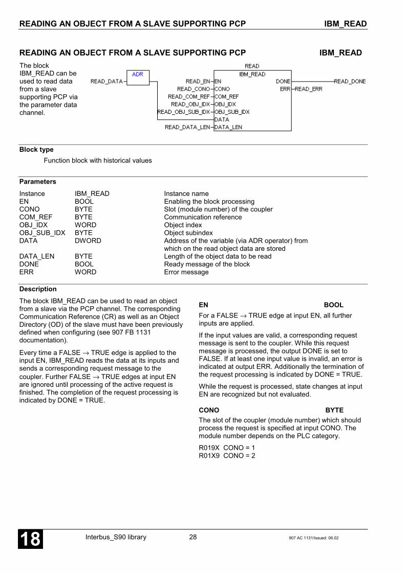
READING AN OBJECT FROM A SLAVE SUPPORTING PCP IBM_READ
Interbus_S90 library 28 907 AC 1131/Issued: 06.0218
READING AN OBJECT FROM A SLAVE SUPPORTING PCP IBM_READThe blockIBM_READ can beused to read datafrom a slavesupporting PCP viathe parameter datachannel.
Block typeFunction block with historical values
ParametersInstance IBM_READ Instance nameEN BOOL Enabling the block processingCONO BYTE Slot (module number) of the couplerCOM_REF BYTE Communication referenceOBJ_IDX WORD Object indexOBJ_SUB_IDX BYTE Object subindexDATA DWORD Address of the variable (via ADR operator) from
which on the read object data are storedDATA_LEN BYTE Length of the object data to be readDONE BOOL Ready message of the blockERR WORD Error message
DescriptionThe block IBM_READ can be used to read an objectfrom a slave via the PCP channel. The correspondingCommunication Reference (CR) as well as an ObjectDirectory (OD) of the slave must have been previouslydefined when configuring (see 907 FB 1131documentation).
Every time a FALSE → TRUE edge is applied to theinput EN, IBM_READ reads the data at its inputs andsends a corresponding request message to thecoupler. Further FALSE → TRUE edges at input ENare ignored until processing of the active request isfinished. The completion of the request processing isindicated by DONE = TRUE.
EN BOOLFor a FALSE → TRUE edge at input EN, all furtherinputs are applied.
If the input values are valid, a corresponding requestmessage is sent to the coupler. While this requestmessage is processed, the output DONE is set toFALSE. If at least one input value is invalid, an error isindicated at output ERR. Additionally the termination ofthe request processing is indicated by DONE = TRUE.
While the request is processed, state changes at inputEN are recognized but not evaluated.
CONO BYTEThe slot of the coupler (module number) which shouldprocess the request is specified at input CONO. Themodule number depends on the PLC category.
R019X CONO = 1R01X9 CONO = 2

READING AN OBJECT FROM A SLAVE SUPPORTING PCP IBM_READ
907 AC 1131/Issued: 06.02 29 Interbus_S90 library 18
COM_REF BYTEThe Communication Reference (CR) number isspecified at input COM_REF. Valid values are 2 to 63.Using the Communication Reference, the device isindirectly selected which data are to be read. For thecorresponding number refer to the CommunicationRelationship List (CRL) in the 907 FB 1131configuration data.
OBJ_IDX WORDThe index of the object to be read from the slave isspecified at input OBJ_IDX. Generally, all values (0 – 65535) are valid for OBJ_IDX, but the access tounconfigured objects causes an error. For theconfigured objects and the corresponding indices(Obj.Idx.) refer to the Object Directory (OD) of thespecific device in the 907 FB 1131 configuration data.
OBJ_SUB_IDX BYTEThe subindex of the object to be read from the slave isspecified at input OBJ_SUB_IDX. Generally, all values(0 – 255) are valid for OBJ_SUB_IDX, but the accessto unconfigured objects causes an error. For theaccess to a single variable only OBJ_SUB_IDX = 0 isallowed. If an object of the type ARRAY is accessedusing OBJ_SUB_IDX = 0, the complete ARRAY isread. The access to a single element of the ARRAY isdone with OBJ_SUB_IDX unequal to 0. Here it has tobe observed that the first element of an ARRAY alwayshas the subindex 1 (ARRAY [1..X]).
For the formats of the configured objects and theallowed subindices refer to the Object Directory (OD) ofthe specific device in the 907 FB 1131 configurationdata.
DATA DWORDThe address of the variable, to which the read objectdata are to be written, is specified at the input DATA viathe ADR operator.
It must be absolutely observed that enough memoryarea is available after this address in order to store theexpected data volume. To be able to interpret thereceived data, also the format of the variables has tocorrespond to the format of the object specified usingOBJ_IDX and OBJ_SUB_IDX.
If the object to be read is for example an INT-ARRAYwith 32 elements (OBJ_SUB_IDX = 0), a variable of thetype ARRAY [1..32] OF INT has to be generated and itsstart address has to be applied to the input DATA usingthe ADR operator.
Using the block IBM_READ objects with a length of upto 240 bytes can be read. If the object size exceeds thismaximum size, reading must be performed sequentiallyduring several successive procedures.
For the formats of the configured objects refer to theObject Directory (OD) of the specific device in the907 FB 1131 configuration data.
The received object data stored beginning at addressDATA are only valid if DONE = TRUE and ERR = 0.
DATA_LEN BYTEAt input DATA_LEN, the length of the object data to beread and stored beginning at address DATA isspecified as a byte value. DATA_LEN must correspondto the object specified using COM_REF, OBJ_IDX andOBJ_SUB_IDX. If the data length received by the slavediffers from DATA_LEN, an error is reported and thedata are not transmitted to the control system. For eachprocedure a maximum of 240 bytes of data can bewritten. If the object size exceeds this maximum size,writing must be performed sequentially during severalsuccessive procedures.
DONE BOOLThe output DONE reflects the processing state. If theblock is trigged by a FALSE → TRUE edge at input EN,DONE is set to FALSE. This indicates that the requestis in progress. If processing of the task is completed,DONE is set to TRUE for one cycle period.
The values at the block outputs are only valid ifDONE = TRUE. The object data are only valid if alsoERR = 0. If ERR is not equal to 0, an error occurred.

READING AN OBJECT FROM A SLAVE SUPPORTING PCP IBM_READ
Interbus_S90 library 30 907 AC 1131/Issued: 06.0218
ERR WORDERR outputs an error ID if an invalid value was appliedto an input or if an error occurred during requestprocessing. ERR has always to be considered inconjunction with output DONE. The ERR output valueis only valid if DONE = TRUE. The encoding of theerror messages available at ERR applies to all Interbusblocks and is explained in section "ERR – Errormessages of the Interbus blocks".
Note:The inputs and outputs can neither be duplicated norinverted.
Function call in ILCAL READ_DATA(EN := READ_EN,CONO := READ_CONO,COM_REF := READ_COM_REF,OBJ_IDX := READ_OBJ_IDX,OBJ_SUB_IDX := READ_OBJ_SUB_IDX,DATA := READ_DATA;DATA_LEN := READ_DATA_LEN),
LD READ.DONEST READ_DONELD READ.ERRST READ_ERR
Note:In IL, the function call has to be performed in oneline.
Function call in STREAD(EN := READ_EN,CONO := READ_CONO,COM_REF := READ_COM_REF,OBJ_IDX := READ_OBJ_IDX,OBJ_SUB_IDX := READ_OBJ_SUB_IDX,DATA := ADR(READ_DATA),DATA_LEN := READ_DATA_LEN);
READ_DONE := READ.DONE;READ_ERR := READ.ERR;

ENABLING THE READING OF AN OBJECT FROM THECONTROL SYSTEM VIA A SLAVE SUPPORTING PCP IBM_READ_EN
907 AC 1131/Issued: 06.02 31 Interbus_S90 library 18
ENABLING THE READING OF AN OBJECT FROM THECONTROL SYSTEM VIA A SLAVE SUPPORTING PCP IBM_READ_ENThe block IBM_READ_ENallows a slave toindependently read datafrom the control system viathe parameter datachannel.
Block typeFunction block with historical values
ParametersInstance IBM_READ_EN Instance nameEN BOOL Enabling the block processingCONO BYTE Slot (module number) of the couplerCOM_REF BYTE Communication referenceOBJ_IDX WORD Object indexOBJ_SUB_IDX BYTE Object subindexDATA DWORD Address from which on the data to be written are
stored (via ADR operator)DATA_LEN BYTE Length of data enabled for writingDONE BOOL Ready message of the blockERR WORD Error message
DescriptionThe block IBM_READ_EN enables a slave toindependently read an object from the control systemvia the PCP channel. The correspondingCommunication Reference (CR) as well as an ObjectDirectory (OD) of the slave must have been previouslydefined when configuring.
The block IBM_READ_EN is activated by aFALSE → TRUE edge at input EN. The values appliedto the block inputs at this time are taken. The block isactive while EN = TRUE. In this state the blockautomatically processes all read requests of a slavewhose parameters COM_REF, OBJ_IDX andOBJ_SUB_IDX match to the parameters which wereapplied to the block inputs on activation(FALSE → TRUE edge at input EN). After eachprocessing of a slave request, the block sets the outputDONE to TRUE for one cycle and displays an error atthe output ERR, if occurred.
To change the parameters COM_REF, OBJ_IDX andOBJ_SUB_IDX, the block has to be deactivated first(EN = FALSE) and after the modification it has to bereactivated using the block inputs.
EN BOOL
For a FALSE → TRUE edge at input EN, all furtherinputs are applied.
If valid values are applied to the inputs, it is cyclicallychecked whether a read request of a slave according tothe inputs COM_REF, OBJ_IDX and OBJ_SUB_IDXexists. If so, the coupler automatically sends the datawith the length DATA_LEN available at the input DATAto the slave and signalizes this by setting the outputDONE to TRUE for one cycle period. If at least oneinput value is invalid, an error is indicated at outputERR. Additionally the termination of the requestprocessing is indicated by DONE = TRUE.
The block can be deactivated with EN = FALSE.
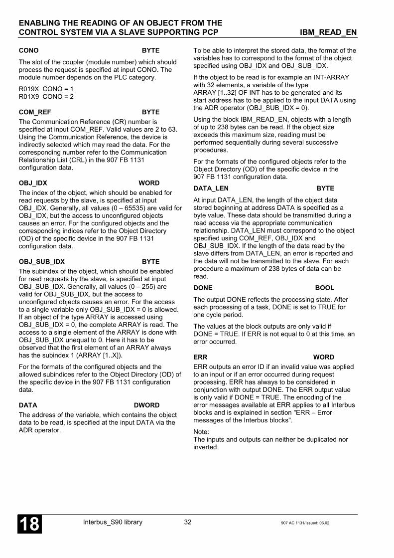
ENABLING THE READING OF AN OBJECT FROM THECONTROL SYSTEM VIA A SLAVE SUPPORTING PCP IBM_READ_EN
Interbus_S90 library 32 907 AC 1131/Issued: 06.0218
CONO BYTEThe slot of the coupler (module number) which shouldprocess the request is specified at input CONO. Themodule number depends on the PLC category.
R019X CONO = 1R01X9 CONO = 2
COM_REF BYTEThe Communication Reference (CR) number isspecified at input COM_REF. Valid values are 2 to 63.Using the Communication Reference, the device isindirectly selected which may read the data. For thecorresponding number refer to the CommunicationRelationship List (CRL) in the 907 FB 1131configuration data.
OBJ_IDX WORDThe index of the object, which should be enabled forread requests by the slave, is specified at inputOBJ_IDX. Generally, all values (0 – 65535) are valid forOBJ_IDX, but the access to unconfigured objectscauses an error. For the configured objects and thecorresponding indices refer to the Object Directory(OD) of the specific device in the 907 FB 1131configuration data.
OBJ_SUB_IDX BYTEThe subindex of the object, which should be enabledfor read requests by the slave, is specified at inputOBJ_SUB_IDX. Generally, all values (0 – 255) arevalid for OBJ_SUB_IDX, but the access tounconfigured objects causes an error. For the accessto a single variable only OBJ_SUB_IDX = 0 is allowed.If an object of the type ARRAY is accessed usingOBJ_SUB_IDX = 0, the complete ARRAY is read. Theaccess to a single element of the ARRAY is done withOBJ_SUB_IDX unequal to 0. Here it has to beobserved that the first element of an ARRAY alwayshas the subindex 1 (ARRAY [1..X]).
For the formats of the configured objects and theallowed subindices refer to the Object Directory (OD) ofthe specific device in the 907 FB 1131 configurationdata.
DATA DWORDThe address of the variable, which contains the objectdata to be read, is specified at the input DATA via theADR operator.
To be able to interpret the stored data, the format of thevariables has to correspond to the format of the objectspecified using OBJ_IDX and OBJ_SUB_IDX.
If the object to be read is for example an INT-ARRAYwith 32 elements, a variable of the typeARRAY [1..32] OF INT has to be generated and itsstart address has to be applied to the input DATA usingthe ADR operator (OBJ_SUB_IDX = 0).
Using the block IBM_READ_EN, objects with a lengthof up to 238 bytes can be read. If the object sizeexceeds this maximum size, reading must beperformed sequentially during several successiveprocedures.
For the formats of the configured objects refer to theObject Directory (OD) of the specific device in the907 FB 1131 configuration data.
DATA_LEN BYTEAt input DATA_LEN, the length of the object datastored beginning at address DATA is specified as abyte value. These data should be transmitted during aread access via the appropriate communicationrelationship. DATA_LEN must correspond to the objectspecified using COM_REF, OBJ_IDX andOBJ_SUB_IDX. If the length of the data read by theslave differs from DATA_LEN, an error is reported andthe data will not be transmitted to the slave. For eachprocedure a maximum of 238 bytes of data can beread.
DONE BOOLThe output DONE reflects the processing state. Aftereach processing of a task, DONE is set to TRUE forone cycle period.
The values at the block outputs are only valid ifDONE = TRUE. If ERR is not equal to 0 at this time, anerror occurred.
ERR WORDERR outputs an error ID if an invalid value was appliedto an input or if an error occurred during requestprocessing. ERR has always to be considered inconjunction with output DONE. The ERR output valueis only valid if DONE = TRUE. The encoding of theerror messages available at ERR applies to all Interbusblocks and is explained in section "ERR – Errormessages of the Interbus blocks".
Note:The inputs and outputs can neither be duplicated norinverted.

ENABLING THE READING OF AN OBJECT FROM THECONTROL SYSTEM VIA A SLAVE SUPPORTING PCP IBM_READ_EN
907 AC 1131/Issued: 06.02 33 Interbus_S90 library 18
Function call in ILLD READ_EN_DATAADRST ADR_RAED_EN_DATA
CAL READ_EN(EN := READ_EN_EN,CONO := READ_EN_CONO,COM_REF := READ_EN_COM_REF,OBJ_IDX := READ_EN_OBJ_IDXOBJ_SUB_IDX := READ_EN_OBJ_SUB_IDX,DATA := ADR_READ_EN_DATA,DATA_LEN := READ_EN_DATA_LEN)
LD READ_EN.DONEST READ_EN_DONELD READ_EN.ERRST READ_EN_ERR
Note:In IL, the function call has to be performed in oneline.
Function call in STREAD_EN(EN := READ_EN_EN,CONO := READ_EN_CONO,COM_REF := READ_EN_COM_REF,OBJ_IDX := READ_EN_OBJ_IDX,OBJ_SUB_IDX := READ_EN_OBJ_SUB_IDX,DATA := ADR(READ_EN_DATA),DATA_LEN := READ_EN_DATA_LEN);
READ_EN_DONE := READ_EN.DONE;READ_EN_ERR := READ_EN.ERR;

WRITING AN OBJECT TO A SLAVE SUPPORTING PCP IBM_WRITE
Interbus_S90 library 34 907 AC 1131/Issued: 06.0218
WRITING AN OBJECT TO A SLAVE SUPPORTING PCP IBM_WRITEThe blockIBM_WRITE canbe used to writean object to aslave supportingPCP via theparameter datachannel.
Block typeFunction block with historical values
ParametersInstance IBM_WRITE Instance nameEN BOOL Enabling the block processingCONO BYTE Slot (module number) of the couplerCOM_REF BYTE Communication referenceOBJ_IDX WORD Object indexOBJ_SUB_IDX BYTE Object subindexDATA DWORD Address (via ADR operator) from which on the object data to
be written are storedDATA_LEN BYTE Length of the object data to be writtenDONE BOOL Ready message of the blockERR WORD Error message
DescriptionThe block IBM_WRITE can be used to write an objectto a slave via the PCP channel. The correspondingCommunication Reference (CR) as well as an ObjectDirectory (OD) of the slave must have been previouslydefined when configuring.
Every time a FALSE → TRUE edge is applied to theinput EN, IBM_WRITE reads the data at its inputs andsends a corresponding request message to thecoupler. Further FALSE → TRUE edges at input ENare ignored until processing of the active request isfinished. The completion of the request processing isindicated by DONE = TRUE.
EN BOOLThe block is activated with a FALSE → TRUE edge atinput EN. The values applied to the block inputs at thistime are taken.
If valid values are applied to the inputs, it is cyclicallychecked whether a write request of a slave accordingto the inputs COM_REF, OBJ_IDX and OBJ_SUB_IDXexists. If so, the received data with the lengthDATA_LEN are automatically written to the variableaddress which was specified at the input DATA whenthe FALSE → TRUE edge at EN was applied. This issignalized by setting the output DONE to TRUE for onecycle period. If at least one input value is invalid, anerror is indicated at output ERR. Additionally thetermination of the request processing is indicated byDONE = TRUE.
The block can be deactivated with EN = FALSE.

WRITING AN OBJECT TO A SLAVE SUPPORTING PCP IBM_WRITE
907 AC 1131/Issued: 06.02 35 Interbus_S90 library 18
CONO BYTEThe slot of the coupler (module number) which shouldprocess the request is specified at input CONO. Themodule number depends on the PLC category.
R019X CONO = 1R01X9 CONO = 2
COM_REF BYTEThe Communication Reference (CR) number isspecified at input COM_REF. Valid values are 2 to 63.Using the Communication Reference, the device isindirectly selected to which the data are to be written.For the corresponding number refer to theCommunication Relationship List (CRL) in the907 FB 1131 configuration data.
OBJ_IDX WORDThe index of the object to be written in the slave isspecified at input OBJ_IDX. Generally, all values (0 – 65535) are valid for OBJ_IDX, but the access tounconfigured objects causes an error. For theconfigured objects and the corresponding indices referto the Object Directory (OD) of the specific device inthe 907 FB 1131 configuration data.
OBJ_SUB_IDX BYTEThe subindex of the object to be written in the slave isspecified at input OBJ_SUB_IDX. Generally, all values(0 – 255) are valid for OBJ_SUB_IDX, but the accessto unconfigured objects causes an error. For theaccess to a single variable only OBJ_SUB_IDX = 0 isallowed. If an object of the type ARRAY is accessedusing OBJ_SUB_IDX = 0, the complete ARRAY iswritten. The access to a single element of the ARRAYis done with OBJ_SUB_IDX unequal to 0. Here it has tobe observed that the first element of an ARRAY alwayshas the subindex 1 (ARRAY [1..X]).
For the formats of the configured objects and theallowed subindices refer to the Object Directory (OD) ofthe specific device in the 907 FB 1131 configurationdata.
DATA DWORDThe address of the variable, which contains the objectdata transmitted by the slave, is specified at the inputDATA via the ADR operator.
To ensure the correct data format, the format of thevariables has to correspond to the format of the objectspecified using OBJ_IDX and OBJ_SUB_IDX.If the object to be written is for example an INT-ARRAYwith 32 elements, a variable of the typeARRAY [1..32] OF INT has to be generated and itsstart address has to be applied to the input DATA usingthe ADR operator (OBJ_SUB_IDX = 0).
If the object is for example an INT-ARRAY with 32elements, a variable of the type ARRAY [1..32] OF INThas to be generated and its start address has to beapplied to the input DATA using the ADR operator(OBJ_SUB_IDX = 0).
For the formats of the configured objects refer to theObject Directory (OD) of the specific device in the907 FB 1131 configuration data. The length of the datato be written (specified as byte value) has also to beapplied to input DATA_LEN.
The write process was successfully completed, ifDONE = TRUE and ERR = 0. For DONE = TRUE andERR unequal to 0, an error occurred and the data werenot written. The error cause can be determined byevaluating the output ERR with the help of the tablelisted below.
The received object data stored beginning at addressDATA are only valid if DONE = TRUE and ERR = 0.
DATA_LEN BYTEAt input DATA_LEN, the length of the object data to bewritten and stored beginning at address DATA isspecified as a byte value. DATA_LEN must correspondto the object specified using COM_REF, OBJ_IDX andOBJ_SUB_IDX. If the object length in the slave differsfrom DATA_LEN, an error is reported and the data willnot be written to the slave. For each procedure amaximum of 240 bytes of data can be written. If theobject size exceeds this maximum size, writing must beperformed sequentially during several successiveprocedures.
DONE BOOLThe output DONE reflects the processing state. If theblock is trigged by a FALSE → TRUE edge at input EN,DONE is set to FALSE. This indicates that the requestis in progress. If processing of the task is completed,DONE is set to TRUE for one cycle period.
The values at the block outputs are only valid ifDONE = TRUE. If ERR is not equal to 0 at this time, anerror occurred.

WRITING AN OBJECT TO A SLAVE SUPPORTING PCP IBM_WRITE
Interbus_S90 library 36 907 AC 1131/Issued: 06.0218
ERR WORDERR outputs an error ID if an invalid value was appliedto an input or if an error occurred during requestprocessing. ERR has always to be considered inconjunction with output DONE. The ERR output valueis only valid if DONE = TRUE. The encoding of theerror messages available at ERR applies to all Interbusblocks and is explained in section "ERR – Errormessages of the Interbus blocks".
Note:The inputs and outputs can neither be duplicated norinverted.
Function call in ILLD WRITE_DATAADRST ADR_WRITE_DATA
CAL WRITE_DATA(EN := WRITE_EN,CONO := WRITE_CONO,COM_REF := WRITE_COM_REF,OBJ_IDX := WRITE_OBJ_IDX,OBJ_SUB_IDX := WRITE_OBJ_SUB_IDX,DATA := ADR_WRITE_DATA;DATA_LEN := WRITE_DATA_LEN),
LD WRITE.DONEST WRITE_DONELD WRITE.ERRST WRITE.ERR
Note:In IL, the function call has to be performed in oneline.
Function call in STWRITE(EN := WRITE_EN,CONO := WRITE_CONO,COM_REF := WRITE_COM_REF,OBJ_IDX := WRITE_OBJ_IDX,OBJ_SUB_IDX := WRITE_OBJ_SUB_IDX,DATA := ADR(WRITE_DATA),DATA_LEN := WRITE_DATA_LEN);
WRITE_DONE := WRITE.DONE;WRITE_ERR := WRITE.ERR;

ENABLING THE WRITING OF AN OBJECT BY A SLAVESUPPORTING PCP IBM_WRITE_EN
907 AC 1131/Issued: 06.02 37 Interbus_S90 library 18
ENABLING THE WRITING OF AN OBJECT BY A SLAVESUPPORTING PCP IBM_WRITE_ENThe block IBM_WRITE_ENallows a slave toindependently write data tothe control system via theparameter data channel.
Block typeFunction block with historical values
ParametersInstance IBM_WRITE_EN Instance nameEN BOOL Enabling the block processingCONO BYTE Slot (module number) of the couplerCOM_REF BYTE Communication referenceOBJ_IDX WORD Object indexOBJ_SUB_IDX BYTE Object subindexDATA DWORD Address from which on the data enabled for
writing are stored (via ADR operator)DATA_LEN BYTE Length of data enabled for writingDONE BOOL Ready message of the blockERR WORD Error message
DescriptionThe block IBM_WRITE_EN enables a slave toindependently write an object to the control system viathe PCP channel. The corresponding CommunicationReference (CR) as well as an Object Directory (OD) ofthe slave must have been previously defined whenconfiguring.
The block IBM_WRITE_EN is activated by aFALSE → TRUE edge at input EN. The values appliedto the block inputs at this time are taken. The blockIBM_WRITE_EN is active while EN = TRUE. In thisstate the block processes automatically all writerequests of a slave whose parameters COM_REF,OBJ_IDX and OBJ_SUB_IDX match to the parameterswhich were applied to the block inputs on activation(FALSE → TRUE edge at input EN). After eachprocessing of a slave request, the block sets the outputDONE to TRUE for one cycle and displays an error atthe output ERR, if occurred.
To change the parameters COM_REF, OBJ_IDX andOBJ_SUB_IDX, the block has to be deactivated first(EN = FALSE) and after the modification it has to bereactivated using the block inputs.
EN BOOL
The block is activated with a FALSE → TRUE edge atinput EN. The values applied to the block inputs at thistime are taken.
If valid values are applied to the inputs, it is cyclicallychecked whether a write request of a slave accordingto the inputs COM_REF, OBJ_IDX and OBJ_SUB_IDXexists. If so, the received data with the lengthDATA_LEN are automatically written to the variableaddress which was specified at the input DATA whenthe FALSE → TRUE edge at EN was applied. This issignalized by setting the output DONE to TRUE for onecycle period. If at least one input value is invalid, anerror is indicated at output ERR. Additionally, thetermination of the request processing is indicated byDONE = TRUE.
The block can be deactivated with EN = FALSE.
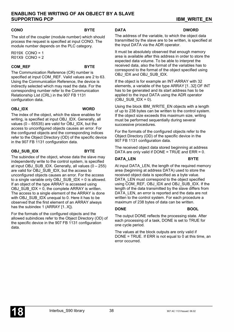
ENABLING THE WRITING OF AN OBJECT BY A SLAVESUPPORTING PCP IBM_WRITE_EN
Interbus_S90 library 38 907 AC 1131/Issued: 06.0218
CONO BYTEThe slot of the coupler (module number) which shouldprocess the request is specified at input CONO. Themodule number depends on the PLC category.
R019X CONO = 1R01X9 CONO = 2
COM_REF BYTEThe Communication Reference (CR) number isspecified at input COM_REF. Valid values are 2 to 63.Using the Communication Reference, the device isindirectly selected which may read the data. For thecorresponding number refer to the CommunicationRelationship List (CRL) in the 907 FB 1131configuration data.
OBJ_IDX WORDThe index of the object, which the slave enables forwriting, is specified at input OBJ_IDX. Generally, allvalues (0 – 65535) are valid for OBJ_IDX, but theaccess to unconfigured objects causes an error. Forthe configured objects and the corresponding indicesrefer to the Object Directory (OD) of the specific devicein the 907 FB 1131 configuration data.
OBJ_SUB_IDX BYTEThe subindex of the object, whose data the slave mayindependently write to the control system, is specifiedat input OBJ_SUB_IDX. Generally, all values (0 – 255)are valid for OBJ_SUB_IDX, but the access tounconfigured objects causes an error. For the accessto a single variable only OBJ_SUB_IDX = 0 is allowed.If an object of the type ARRAY is accessed usingOBJ_SUB_IDX = 0, the complete ARRAY is written.The access to a single element of the ARRAY is donewith OBJ_SUB_IDX unequal to 0. Here it has to beobserved that the first element of an ARRAY alwayshas the subindex 1 (ARRAY [1..X]).
For the formats of the configured objects and theallowed subindices refer to the Object Directory (OD) ofthe specific device in the 907 FB 1131 configurationdata.
DATA DWORDThe address of the variable, to which the object datatransmitted by the slave are to be written, is specified atthe input DATA via the ADR operator.
It must be absolutely observed that enough memoryarea is available after this address in order to store theexpected data volume. To be able to interpret thereceived data, also the format of the variables has tocorrespond to the format of the object specified usingOBJ_IDX and OBJ_SUB_IDX.
If the object is for example an INT-ARRAY with 32elements, a variable of the type ARRAY [1..32] OF INThas to be generated and its start address has to beapplied to the input DATA using the ADR operator(OBJ_SUB_IDX = 0).
Using the block IBM_WRITE_EN objects with a lengthof up to 238 bytes can be written to the control system.If the object size exceeds this maximum size, writingmust be performed sequentially during severalsuccessive procedures.
For the formats of the configured objects refer to theObject Directory (OD) of the specific device in the907 FB 1131 configuration data.
The received object data stored beginning at addressDATA are only valid if DONE = TRUE and ERR = 0.
DATA_LEN BYTEAt input DATA_LEN, the length of the required memoryarea (beginning at address DATA) used to store thereceived object data is specified as a byte value.DATA_LEN must correspond to the object specifiedusing COM_REF, OBJ_IDX and OBJ_SUB_IDX. If thelength of the data transmitted by the slave differs fromDATA_LEN, an error is reported and the data are notwritten to the control system. For each procedure amaximum of 238 bytes of data can be written.
DONE BOOLThe output DONE reflects the processing state. Aftereach processing of a task, DONE is set to TRUE forone cycle period.
The values at the block outputs are only valid ifDONE = TRUE. If ERR is not equal to 0 at this time, anerror occurred.

ENABLING THE WRITING OF AN OBJECT BY A SLAVESUPPORTING PCP IBM_WRITE_EN
907 AC 1131/Issued: 06.02 39 Interbus_S90 library 18
ERR WORDERR outputs an error ID if an invalid value was appliedto an input or if an error occurred during requestprocessing. ERR has always to be considered inconjunction with output DONE. The ERR output valueis only valid if DONE = TRUE. The encoding of theerror messages available at ERR applies to all Interbusblocks and is explained in section "ERR – Errormessages of the Interbus blocks".
Note:The inputs and outputs can neither be duplicated norinverted.
Function call in ILLD WRITE_EN_DATAADRST ADR_WRITE_EN_DATA
CAL WRITE_EN(EN := WRITE_EN_EN,CONO := WRITE_EN_CONO,COM_REF := WRITE_EN_COM_REF,OBJ_IDX := WRITE_EN_OBJ_IDXOBJ_SUB_IDX := WRITE_EN_OBJ_SUB_IDX,DATA := ADR_WRITE_EN_DATA,DATA_LEN := WRITE_EN_DATA_LEN)
LD WRITE_EN.DONEST WRITE_EN_DONELD WRITE_EN.ERRST WRITE_EN_ERR
Note:In IL, the function call has to be performed in oneline.
Function call in STWRITE_EN(EN := WRITE_EN_EN,CONO := WRITE_EN_CONO,COM_REF := WRITE_EN_COM_REF,OBJ_IDX := WRITE_EN_OBJ_IDX,OBJ_SUB_IDX := WRITE_EN_OBJ_SUB_IDX,DATA := ADR(WRITE_EN_DATA),DATA_LEN := WRITE_EN_DATA_LEN);
WRITE_EN_DONE:= WRITE_EN.DONE;WRITE_EN_ERR := WRITE_EN.ERR;

Interbus_S90 library 40 907 AC 1131/Issued: 06.0218
Glossary
BOOLVariables of the type BOOL can have the values TRUE and FALSE. For this, 8 bit memory space are reserved.
DINTDINT belongs to the integer data types.
The different numerical types are responsible for a different numerical range. For integer data types the followingrange limits are valid:
Type Lower limit Upper limit Memory spaceDINT -2147483648 2147483647 32 bit
Due to this, it is possible that information are lost during the conversion of greater data types to smaller data types.
DWORDDWORD belongs to the integer data types.
The different numerical types are responsible for a different numerical range. For integer data types the followingrange limits are valid:
Type Lower limit Upper limit Memory spaceDWORD 0 4294967295 32 bit
Due to this, it is possible that information are lost during the conversion of greater data types to smaller data types.
INTINT belongs to the integer data types.
The different numerical types are responsible for a different numerical range. For integer data types the followingrange limits are valid:
Type Lower limit Upper limit Memory spaceINT -32768 32767 16 bit
Due to this, it is possible that information are lost during the conversion of greater data types to smaller data types.
WORDWORD belongs to the integer data types.
The different numerical types are responsible for a different numerical range. For integer data types the followingrange limits are valid:
Type Lower limit Upper limit Memory spaceWORD 0 65535 16 bit
Due to this, it is possible that information are lost during the conversion of greater data types to smaller data types.
STRING

907 AC 1131/Issued: 06.02 41 Interbus_S90 library 18
Variables of the type STRING can include any character string. The specified value for the memory spaceallocation in the declaration corresponds to characters and can be defined using parenthesis or brackets. If novalue (1 to 255) is specified, 80 characters are applied by default.
FunctionsFunctions are subroutines which have multiple input parameters and return exactly one result element. Thereturned result can be an elementary or a derived data type. Due to this, a function may also return an array, astructure, an array of structures etc.
For the same input parameters, functions always return the same result (they do not have an internal memory).
Therefore, the following rules can be derived:
• Within functions, global variables can neither be read nor written.• Within functions, it is not allowed to read or write absolute operands.• Within functions, it is not allowed to call function blocks.
Function blocksFunction blocks are subroutines which can have as many inputs, outputs and internal variables as required. Theyare called by a program or by another function block.
As they can be used several times (with different data records), function blocks (code and interface) can beconsidered as type. When assigning an individual data record (declaration) to the function block, a function blockinstance is generated.
In contrast to functions, function blocks can contain statically local data which are saved from one call to the next.This allows for example to realize counters which may not forget their counter value. I.e. function blocks can havean internal memory.
Functions and function blocks differ in two main points:
• A function block has multiple output parameters and a function has a maximum of one output parameter,where the output parameters of functions and function blocks differ syntactically.
• In contrast to a function, a function block can have an internal memory.
1. Function blocks with historical values (memory):
For function blocks with historical values it has to be observed that instance names may not be defined severaltimes if different data sets should be called.
2. Function blocks without historical values (memory):
For function blocks without historical values only one instance has to be defined for the FB type. This instance canbe used for several calls of the FB (also with different I/O values).
The instance name can be defined without any restrictions. The type is preset and identical to the function blockname.

Interbus_S90 library 42 907 AC 1131/Issued: 06.0218
Index
CComponents of the Interbus Library 3
DDEVICESTATUS_1_TYPE 11
EError messages of the Interbus blocks 4
IIBM_COM_ERR_TYPE 17
IBM_GET_OD S90 24
IBM_READ S90 28
IBM_READ_EN S90 31
IBM_SLVDIAG S90 8
IBM_STAT S90 13
IBM_STATE_BITS_TYPE 16
IBM_SYSDIAG S90 22
IBM_WRITE S90 34
IBM_WRITE_EN S90 37
Interbus S90
IBM_SLVDIAG 8
IBM_STAT 13
IBM_SYSDIAG 22
INTERBUS_INFO 6
INTERBUS S90
DEVICESTATUS_1_TYPE 11
IBM_COM_ERR_TYPE 17
IBM_GET_OD 24
IBM_READ 28
IBM_READ_EN 31
IBM_STATE_BITS_TYPE 16
IBM_WRITE 34
IBM_WRITE_EN 37
INTERBUS_INFO S90 6

Software Description Advant Controller 31Intelligent DecentralizedAutomation System
CANopenFunction Block Library90 Series
CANopen90 Series


907 AC 1131/Issued: 05.03 1 CANopen_S90 Library 18
Contents
The CANopen library 3PREREQUISITES FOR USING THE LIBRARY 3COMPONENTS OF THE LIBRARY 3Function blocks 3Data types 4GENERAL NOTES REGARDING CAN BLOCKS 5CAN 2.0 A - 11 bit identifier 5CAN 2.0 B - 29 bit identifier 5DESCRIPTION OF CAN DATA TYPES 6CAN2A_IDENT_TYPE 6CAN2A_MESSAGE_TYPE 7CANopen_IDENT_TYPE 8CANopen_MESSAGE_TYPE 9CAN2B_MESSAGE_TYPE 10ERROR MESSAGES OF THE CANOPEN BLOCKS AND CAN BLOCKS 11Errors at block inputs 11Execution errors, coupler or slave responses 11
Overview of blocks arranged according to their call names 12
Block descriptions 12READING INFORMATION ABOUT THE INSTALLED COUPLERS CANOPEN_INFO 13POLLING DIAGNOSTIC DATA FROM A SLAVE CANOM_NODEDIAG 15RESETTING THE COUPLER'S ERROR INDICATIONS CANOM_RES_ERR 19READING THE CANOPEN COUPLER STATUS CANOM_STAT 21READING A STATUS SURVEY OF ALL SLAVES CANOM_SYSDIAG 26READING AN OBJECT FROM A SLAVE CANOM_SDO_READ 28WRITING AN OBJECT TO A SLAVE CANOM_SDO_WRITE 31CONTROLLING NMT NODE STATES VIA NETWORK MANAGEMENT CANOM_NMT 34GERERATING A GENERAL CAN TELEGRAM HEADER
ACCORDING TO CAN 2.0 A IDENT_CAN2A_TO_WORD 36SPLITTING A GENERAL CAN TELEGRAM HEADER
ACCORDING TO CAN 2.0 A WORD_TO_IDENT_CAN2A 37GENERATING A CANOPEN-SPECIFIC CAN TELEGRAM HEADER
ACCORDING TO CAN 2.0 A IDENT_CANOPEN_TO_WORD 38SPLITTING A CANOPEN-SPECIFIC CAN TELEGRAM HEADER
ACCORDING TO CAN 2.0 A WORD_TO_IDENT_CANOPEN 39RECEIVING CAN TELEGRAMS WITH 11 BIT IDENTIFIERS
ACCORDING TO CAN 2.0 A CAN_REC_2A 40ENABLING OF IDENTIFIERS FOR RECEIVING CAN TELEGRAMS
WITH 11 BIT IDENTIFIERS ACCORDING TO CAN 2.0 A CAN_REC_FILTER_2A 43TRANSMITTING CAN TELEGRAMS WITH 11 BIT IDENTIFIERS
ACCORDING TO CAN 2.0 A CAN_SEND_2A 46RECEIVING CAN TELEGRAMS WITH 29 BIT IDENTIFIERS
ACCORDING TO CAN 2.0 B CAN_REC_2B 49TRANSMITTING CAN TELEGRAMS WITH 29 BIT IDENTIFIERS
ACCORDING TO CAN 2.0 B CAN_SEND_2B 52

CANopen_S90 Library 2 907 AC 1131/Issued: 05.0318
Glossary 54
Index 56

907 AC 1131/Issued: 05.03 3 CANopen_S90 Library 18
The CANopen libraryPREREQUISITES FOR USING THE LIBRARYThe function blocks contained in the CANopen library access both, the PLC run time system as well as directly thecoupler. The definitions and functions required for this are stored in the internal library Coupler_S90_Vxx.LIB.
When using the CANopen library CANopen_Master_S90_V50.LIB, it is absolutely essential to insert alsothe library Coupler_S90_V50.LIB into the project.
COMPONENTS OF THE LIBRARYThe library contains function blocks which allow an easy handling of the CANopen coupler. Additionally variousdata types are defined in this library. These structures enable a clear presentation of data sets.
Function blocksThe CANopen library contains the following function blocks:
Group: GeneralCANopen_INFO - Reading information about the installed couplers
Group: CANopen masterStatus / DiagnosisCANoM_NODEDIAG - Polling diagnostic data from a slaveCANoM_RES_ERR - Resetting internal error indications and countersCANoM_STAT - Reading the CANopen coupler statusCANoM_SYSDIAG - Displaying status information of all slavesSDOCANoM_SDO_READ - Reading the value of a slave objectCANoM_SDO_WRITRE - Writing the value of a slave objectNMTCANoM_NMT - Changing the operational state of one or all slaves
Group: CAN 2.0 A
CAN_REC_2A - Receiving CAN 2.0 A telegrams (11 bit identifier)CAN_REC_FILTER_2A - Setting up receive filters for CAN 2.0 A telegramCAN_SEND_2A - Transmitting CAN 2.0 A telegrams (11 bit identifier)
Group: CAN 2.0 B
CAN_REC_2B - Receiving CAN 2.0 B telegrams (29 bit identifier)CAN_SEND_2B - Transmitting CAN 2.0 B telegrams (29 bit identifier)
Group: Auxiliary functions
IDENT_CAN2A_TO_WORD - Generating a CAN 2.0 A telegram headerWORD_TO_IDENT_CAN2A - Splitting a CAN 2.0 A telegram header into individual componentsIDENT_CANopen_TO_WORD - Generating a CANopen telegram header according to CAN 2.0 AWORD_TO_IDENT_CANopen - Splitting a CANopen telegram header into individual components
Detailed information about the various blocks can be found in the following sections.
THE CANOPEN LIBRARY

THE CANOPEN LIBRARY
CANopen_S90 Library 4 907 AC 1131/Issued: 05.0318
Data types
The following data types (structures) are defined in the CANopen library:
CANopen masterCANoM_COM_ERR_TYPE - Communication errorCANoM_EMCY_TYPE - Emergency telegramCANoM_STATE_BITS_TYPE - Bits for coupler state descriptionNODESTATUS_1_TYPE - Node diagnostics
CANCAN2A_IDENT_TYPE - Components of an 11 bit identifier according to CAN 2.0CAN2A_MESSAGE_TYPE - Telegram structure according to CAN 2.0 ACAN2B_MESSAGE_TYPE - Telegram structure according to CAN 2.0 BCANopen_IDENT_TYPE - Components of a CAN telegram header according to CAN 2.0 ACANopen_MESSAGE_TYPE - Structure of a CANopen telegram with 11 bit identifier acc. to CAN 2.0 A
The data type descriptions for the CANopen master can be found at the corresponding block descriptions. TheCAN data types are described in the following section.
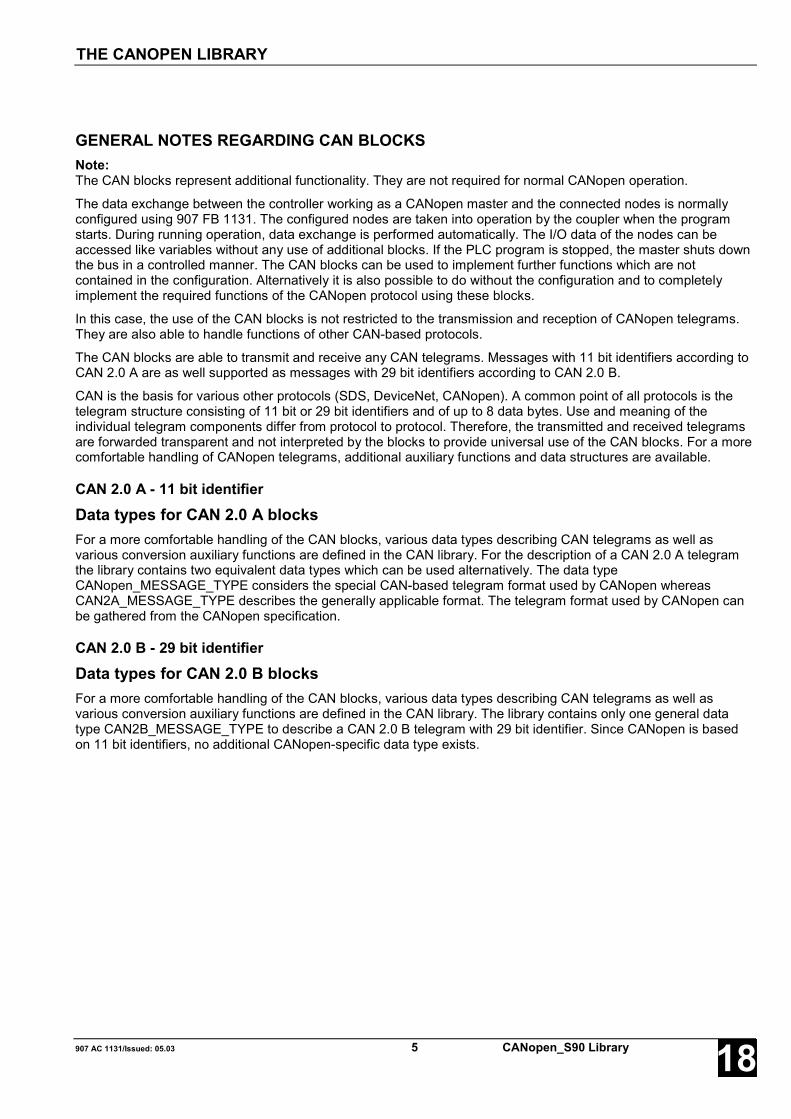
907 AC 1131/Issued: 05.03 5 CANopen_S90 Library 18
GENERAL NOTES REGARDING CAN BLOCKSNote:The CAN blocks represent additional functionality. They are not required for normal CANopen operation.
The data exchange between the controller working as a CANopen master and the connected nodes is normallyconfigured using 907 FB 1131. The configured nodes are taken into operation by the coupler when the programstarts. During running operation, data exchange is performed automatically. The I/O data of the nodes can beaccessed like variables without any use of additional blocks. If the PLC program is stopped, the master shuts downthe bus in a controlled manner. The CAN blocks can be used to implement further functions which are notcontained in the configuration. Alternatively it is also possible to do without the configuration and to completelyimplement the required functions of the CANopen protocol using these blocks.
In this case, the use of the CAN blocks is not restricted to the transmission and reception of CANopen telegrams.They are also able to handle functions of other CAN-based protocols.
The CAN blocks are able to transmit and receive any CAN telegrams. Messages with 11 bit identifiers according toCAN 2.0 A are as well supported as messages with 29 bit identifiers according to CAN 2.0 B.
CAN is the basis for various other protocols (SDS, DeviceNet, CANopen). A common point of all protocols is thetelegram structure consisting of 11 bit or 29 bit identifiers and of up to 8 data bytes. Use and meaning of theindividual telegram components differ from protocol to protocol. Therefore, the transmitted and received telegramsare forwarded transparent and not interpreted by the blocks to provide universal use of the CAN blocks. For a morecomfortable handling of CANopen telegrams, additional auxiliary functions and data structures are available.
CAN 2.0 A - 11 bit identifierData types for CAN 2.0 A blocksFor a more comfortable handling of the CAN blocks, various data types describing CAN telegrams as well asvarious conversion auxiliary functions are defined in the CAN library. For the description of a CAN 2.0 A telegramthe library contains two equivalent data types which can be used alternatively. The data typeCANopen_MESSAGE_TYPE considers the special CAN-based telegram format used by CANopen whereasCAN2A_MESSAGE_TYPE describes the generally applicable format. The telegram format used by CANopen canbe gathered from the CANopen specification.
CAN 2.0 B - 29 bit identifierData types for CAN 2.0 B blocksFor a more comfortable handling of the CAN blocks, various data types describing CAN telegrams as well asvarious conversion auxiliary functions are defined in the CAN library. The library contains only one general datatype CAN2B_MESSAGE_TYPE to describe a CAN 2.0 B telegram with 29 bit identifier. Since CANopen is basedon 11 bit identifiers, no additional CANopen-specific data type exists.
THE CANOPEN LIBRARY
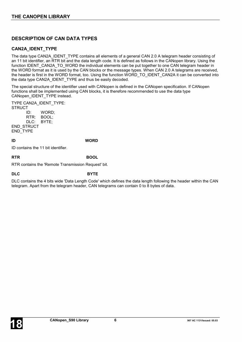
THE CANOPEN LIBRARY
CANopen_S90 Library 6 907 AC 1131/Issued: 05.0318
DESCRIPTION OF CAN DATA TYPES
CAN2A_IDENT_TYPEThe data type CAN2A_IDENT_TYPE contains all elements of a general CAN 2.0 A telegram header consisting ofan 11 bit identifier, an RTR bit and the data length code. It is defined as follows in the CANopen library. Using thefunction IDENT_CAN2A_TO_WORD the individual elements can be put together to one CAN telegram header inthe WORD format as it is used by the CAN blocks or the message types. When CAN 2.0 A telegrams are received,the header is first in the WORD format, too. Using the function WORD_TO_IDENT_CAN2A it can be converted intothe data type CAN2A_IDENT_TYPE and thus be easily decoded.
The special structure of the identifier used with CANopen is defined in the CANopen specification. If CANopenfunctions shall be implemented using CAN blocks, it is therefore recommended to use the data typeCANopen_IDENT_TYPE instead.
TYPE CAN2A_IDENT_TYPE:STRUCT
ID: WORD;RTR: BOOL;DLC: BYTE;
END_STRUCTEND_TYPE
ID WORDID contains the 11 bit identifier.
RTR BOOLRTR contains the 'Remote Transmission Request' bit.
DLC BYTEDLC contains the 4 bits wide 'Data Length Code' which defines the data length following the header within the CANtelegram. Apart from the telegram header, CAN telegrams can contain 0 to 8 bytes of data.

907 AC 1131/Issued: 05.03 7 CANopen_S90 Library 18
CAN2A_MESSAGE_TYPEThe data type CAN2A_MESSAGE_TYPE describes the general structure of a CAN 2.0 A telegram with an 11 bitidentifier. It is defined as follows in the CANopen library.
The special CAN telegram structure used with CANopen is defined in the CANopen specification. If CANopenfunctions shall be implemented using CAN blocks, it is therefore recommended to use the data typeCANopen_MESSAGE_TYPE instead.
TYPE CAN2A_MESSAGE_TYPE:STRUCT
IDENT: WORD;DATA: ARRAY [1..8] OF BYTE;
END_STRUCTEND_TYPE
IDENT WORDIDENT contains the general CAN telegram header consisting of the identifier (11 bit), the data length code (DLC)and the remote transmission request (RTR) in WORD format. Using the function IDENT_CAN2A_TO_WORD,IDENT can be easily composed from the individual components. Conversely IDENT can also be split into itsindividual components using the function WORD_TO_IDENT_CAN2A, if required. IDENT has the following format:
DLC.3 DLC.2 DLC.1 DLC.0 RTR ID.10 ID.9 ID.8 ID.7 ID.6 ID.5 ID.4 ID.3 ID.2 ID.1 ID.015 14 13 12 11 10 9 8 7 6 5 4 3 2 1 0
DATA ARRAY[1..8] OF BYTEDATA contains the data of a general CAN telegram (if available). A CAN telegram can contain 0 to 8 bytes of data.The actual data length of a telegram is described by the data length code (DLC) in the telegram header (refer toIDENT). In DATA, only the first bytes as specified by the DLC are valid.
THE CANOPEN LIBRARY

THE CANOPEN LIBRARY
CANopen_S90 Library 8 907 AC 1131/Issued: 05.0318
CANopen_IDENT_TYPEThe data type CANopen_IDENT_TYPE contains the individual CAN 2.0 A telegram header elements as they areespecially used with CANopen. It consists of the function code, the node ID, the RTR bit and the data length code.The meaning of the individual elements is described in the CANopen specification. Using the functionIDENT_CANopen_TO_WORD the individual elements can be put together to one CANopen telegram header in theWORD format as it is used by the CAN blocks or the message types. When CAN 2.0 A telegrams are received, theheader is first in the WORD format, too. Using the function WORD_TO_IDENT_CANopen it can be converted intothe data type CANopen_IDENT_TYPE and thus be easily decoded.
If CANopen functions shall be implemented by means of CAN blocks, it is recommended to use the special datatype CANopen_IDENT_TYPE. If functions shall be implemented the telegram structure of which does not matchthe CANopen structure, the generally applicable data type CAN2A_IDENT_TYPE can be used instead.
TYPE CANopen_IDENT_TYPE:STRUCT
FCT: BYTE;NODE: BYTE;RTR: BOOL;DLC: BYTE;
END_STRUCTEND_TYPE
FCT BYTEFCT contains the 4 bits wide 'Function Code'. Together with the node ID, the function code represents the 11 bitidentifier.
NODE BYTENODE contains the node ID (0-127) of a CAN node. Together with the function code, the node ID represents the 11bit identifier.
RTR BOOLRTR contains the 'Remote Transmission Request' bit.
DLC BYTEDLC contains the 4 bits wide 'Data Length Code' which defines the data length following the header within theCANopen telegram. Apart from the telegram header, a CANopen telegram can contain 0 to 8 bytes of data, wherethe first 4 bytes are used for special functions and are not available for user data (refer toCANopen_MESSAGE_TYPE).

907 AC 1131/Issued: 05.03 9 CANopen_S90 Library 18
CANopen_MESSAGE_TYPEThe data type CANopen_MESSAGE_TYPE describes the special structure of a CANopen telegram with 11 bitidentifier acc. to CAN 2.0 A.
The special CAN telegram structure used with CANopen is defined in the CANopen specification. This data type isrecommended if CANopen functions shall be implemented using CAN blocks. Implementation of other telegramformats can be done using the data type CAN2A_MESSAGE_TYPE.
TYPE CAN2A_MESSAGE_TYPE:STRUCT
IDENT: WORD;CMD: BYTE;OBJ_IDX: WORD;SUB_IDX: BYTE;DATA: ARRAY [1..4] OF BYTE;
END_STRUCTEND_TYPE
IDENT WORDIDENT contains the CANopen-specific CAN telegram header consisting of the node ID, the function code, the datalength code (DLC) and the remote transmission request (RTR) in WORD format. Using the functionIDENT_CANopen_TO_WORD, IDENT can be easily composed from the individual components. ConverselyIDENT can also be split into its individual components using the function WORD_TO_IDENT_CANopen, if required.IDENT has the following format:
DLC.3 DLC.2 DLC.1 DLC.0 RTR FCT.3 FCT.2 FCT.1 FCT.0 ID.6 ID.5 ID.4 ID.3 ID.2 ID.1 ID.015 14 13 12 11 10 9 8 7 6 5 4 3 2 1 0
CMD BYTECMD contains the 'Command' according to the CANopen specification.
OBJ_IDX WORDOBJ_IDX contains the index of the object to be accessed.
SUB_IDX BYTESUB_IDX contains the sub-index of the object to be accessed.
DATA ARRAY[1..4] OF BYTEDATA contains the data of a CANopen-specific CAN telegram (if available). For CANopen, the first four bytes of aCAN telegram are pre-assigned. Therefore, a maximum of 4 bytes are only available for the user data. The actualdata length of a telegram is described by the data length code (DLC) in the telegram header (refer to IDENT). InDATA, only the first bytes are valid as specified by the DLC (minus the 4 pre-assigned bytes).
THE CANOPEN LIBRARY

THE CANOPEN LIBRARY
CANopen_S90 Library 10 907 AC 1131/Issued: 05.0318
CAN2B_MESSAGE_TYPEThe data type CAN2B_MESSAGE_TYPE describes the general structure of a CAN 2.0 B telegram with a 29 bitidentifier. It is defined as follows in the CANopen library.
TYPE CAN2B_MESSAGE_TYPE:STRUCT
IDENT: DWORD;RTR: BOOL;DLC: BYTE;DATA: ARRAY [1..8] OF BYTE;
END_STRUCTEND_TYPE
IDENT DWORDIDENT contains the general 29 bit identifier, its value range reaches from 0 to 536870911 (16#0 to 16#1FFFFFFF).
RTR BOOLRTR (Remote Transmission Request) contains the RTR bit in the telegram header.
DLC BYTEDLC contains the data length code in the telegram header and specifies the valid length in bytes for the user datafollowing in DATA. Valid values for DLC are 0 to 8.
DATA ARRAY[1..8] OF BYTEDATA contains the telegram data (if available). A CAN telegram can contain 0 to 8 bytes of data. The actual datalength of a telegram is described by the data length code (DLC) in the telegram header (refer to DLC). In DATA,only the first bytes are valid as specified by the DLC.
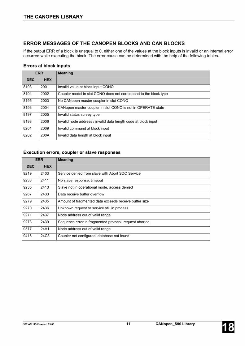
907 AC 1131/Issued: 05.03 11 CANopen_S90 Library 18
ERROR MESSAGES OF THE CANOPEN BLOCKS AND CAN BLOCKSIf the output ERR of a block is unequal to 0, either one of the values at the block inputs is invalid or an internal erroroccurred while executing the block. The error cause can be determined with the help of the following tables.
Errors at block inputsERR Meaning
DEC HEX
8193 2001 Invalid value at block input CONO
8194 2002 Coupler model in slot CONO does not correspond to the block type
8195 2003 No CANopen master coupler in slot CONO
8196 2004 CANopen master coupler in slot CONO is not in OPERATE state
8197 2005 Invalid status survey type
8198 2006 Invalid node address / invalid data length code at block input
8201 2009 Invalid command at block input
8202 200A Invalid data length at block input
Execution errors, coupler or slave responsesERR Meaning
DEC HEX
9219 2403 Service denied from slave with Abort SDO Service
9233 2411 No slave response, timeout
9235 2413 Slave not in operational mode, access denied
9267 2433 Data receive buffer overflow
9279 2435 Amount of fragmented data exceeds receive buffer size
9270 2436 Unknown request or service still in process
9271 2437 Node address out of valid range
9273 2439 Sequence error in fragmented protocol, request aborted
9377 24A1 Node address out of valid range
9416 24C8 Coupler not configured, database not found
THE CANOPEN LIBRARY

OVERVIEW OF BLOCKS ARRANGED ACCORDING TO THEIR CALL NAMES
CANopen_S90 Library 12 907 AC 1131/Issued: 05.0318
Overview of blocks arranged according to their call names
Character description:
FBhv … Function block with historical values
FBnohv… Function block without historical values
F … Function
CE name Type Function Page
CANopen_INFO FBnohv Reading information about the installed couplers 13
CAN_REC_2A FBhv Receiving CAN 2.0 A telegrams (11 bit identifier) 40
CAN_REC_2B FBhv Receiving CAN 2.0 B telegrams (29 bit identifier) 52
CAN_REC_FILTER_2A FBhv Setting up receive filters for CAN 2.0 A telegram 49
CAN_SEND_2A FBhv Transmitting CAN 2.0 A telegrams (11 bit identifier) 46
CAN_SEND_2B FBhv Transmitting CAN 2.0 B telegrams (29 bit identifier) 52
CANoM_NMT FBhv Changing the operational state of one or all slaves 34
CANoM_NODEDIAG FBhv Polling diagnostic data from a slave 15
CANoM_SDO_READ FBhv Reading the value of a slave object 28
CANoM_SDO_WRITRE FBhv Writing the value of a slave object 31
CANoM_RES_ERR FBhv Resetting internal error indications and counters 19
CANoM_STAT FBnohv Reading the CANopen coupler status 21
CANoM_SYSDIAG FBnohv Displaying status information of all slaves 26
IDENT_CAN2A_TO_WORD F Generating a CAN 2.0 A telegram header 36
IDENT_CANopen_TO_WORD F Generating a CANopen telegram headeraccording to CAN 2.0 A
38
WORD_TO_IDENT_CAN2A F Splitting a CAN 2.0 A telegram header into individualcomponents
37
WORD_TO_IDENT_CANopen F Splitting a CANopen telegram header into individualcomponents
39
Block descriptions
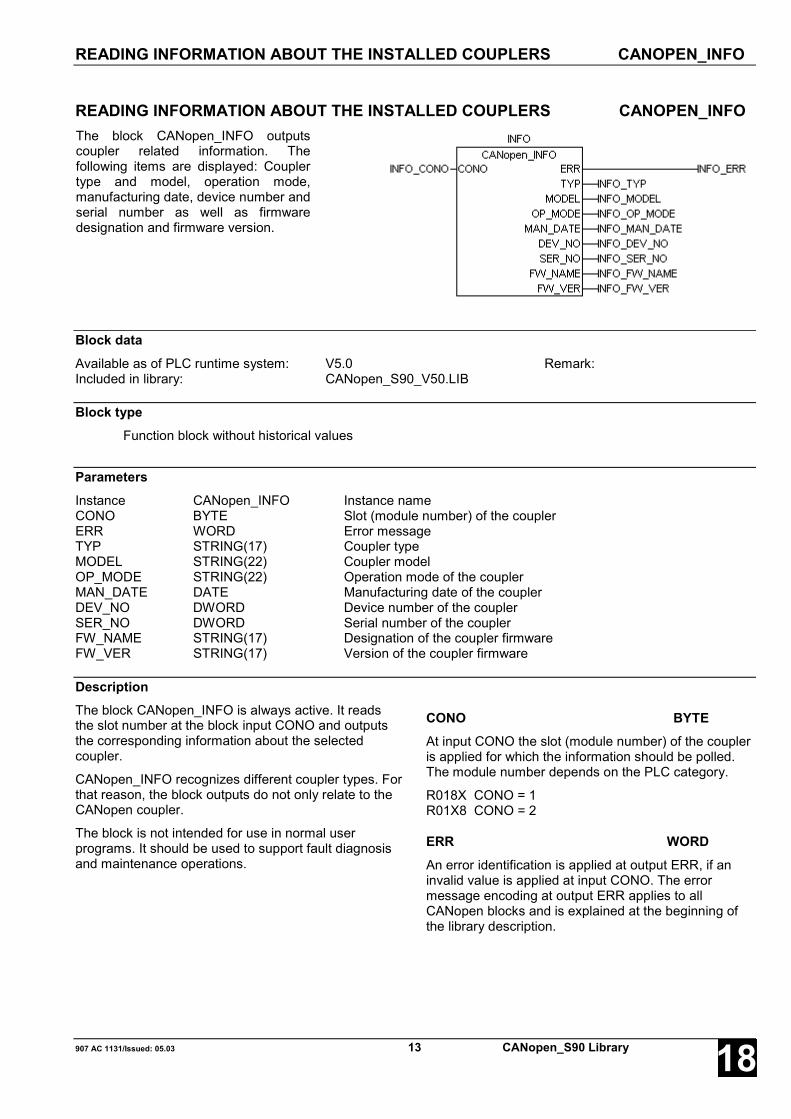
READING INFORMATION ABOUT THE INSTALLED COUPLERS CANOPEN_INFO
907 AC 1131/Issued: 05.03 13 CANopen_S90 Library 18
READING INFORMATION ABOUT THE INSTALLED COUPLERS CANOPEN_INFOThe block CANopen_INFO outputscoupler related information. Thefollowing items are displayed: Couplertype and model, operation mode,manufacturing date, device number andserial number as well as firmwaredesignation and firmware version.
Block dataAvailable as of PLC runtime system: V5.0 Remark:Included in library: CANopen_S90_V50.LIB
Block typeFunction block without historical values
ParametersInstance CANopen_INFO Instance nameCONO BYTE Slot (module number) of the couplerERR WORD Error messageTYP STRING(17) Coupler typeMODEL STRING(22) Coupler modelOP_MODE STRING(22) Operation mode of the couplerMAN_DATE DATE Manufacturing date of the couplerDEV_NO DWORD Device number of the couplerSER_NO DWORD Serial number of the couplerFW_NAME STRING(17) Designation of the coupler firmwareFW_VER STRING(17) Version of the coupler firmware
DescriptionThe block CANopen_INFO is always active. It readsthe slot number at the block input CONO and outputsthe corresponding information about the selectedcoupler.
CANopen_INFO recognizes different coupler types. Forthat reason, the block outputs do not only relate to theCANopen coupler.
The block is not intended for use in normal userprograms. It should be used to support fault diagnosisand maintenance operations.
CONO BYTEAt input CONO the slot (module number) of the coupleris applied for which the information should be polled.The module number depends on the PLC category.
R018X CONO = 1R01X8 CONO = 2
ERR WORDAn error identification is applied at output ERR, if aninvalid value is applied at input CONO. The errormessage encoding at output ERR applies to allCANopen blocks and is explained at the beginning ofthe library description.

READING INFORMATION ABOUT THE INSTALLED COUPLERS CANOPEN_INFO
CANopen_S90 Library 14 907 AC 1131/Issued: 05.0318
TYP STRING(17)Output TYP displays the coupler type (i.e. the couplerdesign). Different types are recognized by the block.
The model ID of the CANopen coupler isMODEL = 'CANopen Master‘.
If the block detects an unknown model, MODELoutputs the value 'unknown‘.
OP_MODE STRING(22)Output OP_MODE displays the current setting for thecoupler operation mode. This output is only applicablefor couplers with switchable operation modes.
Therefore, this output is not used for the CANopencoupler.
MAN_DATE DATEOutput MAN_DATE displays the manufacturing date ofthe coupler. The date is a variable of the data typeDATE and has the format D#YYYY-MM-DD. Its initialvalue is D#2000-01-01.
DEV_NO DWORDOutput DEV_NO outputs the device number of thecoupler.
SER_NO DWORDOutput SER_NO outputs the serial number of thecoupler.
FW_NAME STRING(17)At output FW_NAME the designation of the couplerfirmware is applied.
FW_VER STRING(17)Output FW_VER displays the firmware release number(version) and the firmware issue date of the coupler.These data are represented as a string (e.g. 'V1.00315.07.00‘).
Function call in ILCAL INFO(CONO := INFO_CONO)
LD INFO.ERRST INFO_ERRLD INFO.TYPST INFO_TYPLD INFO.MODELST INFO_MODELLD INFO.OP_MODEST INFO_OP_MODELD INFO.MAN_DATEST INFO_MAN_DATELD INFO.DEV_NOST INFO_DEV_NOLD INFO.SER_NOST INFO_SER_NOLD INFO.FW_NAMEST INFO_FW_NAMELD INFO.FW_VERST INFO_FW_VER
Note:In IL, the function call has to be performed in oneline.
Function call in STINFO(CONO := INFO_CONO);INFO_ERR:=INFO.ERR;INFO_TYP:=INFO.TYP;INFO_MODEL:=INFO.MODEL;INFO_OP_MODE:=INFO.OP_MODE;INFO_MAN_DATE:=INFO.MAN_DATE;INFO_DEV_NO:=INFO.DEV_NO;INFO_SER_NO:=INFO.SER_NO;INFO_FW_NAME:=INFO.FW_NAME;INFO_FW_VER:=INFO.FW_VER;

POLLING DIAGNOSTIC DATA FROM A SLAVE CANOM_NODEDIAG
907 AC 1131/Issued: 05.03 15 CANopen_S90 Library 18
POLLING DIAGNOSTIC DATA FROM A SLAVE CANOM_NODEDIAGThe block CANoM_NODEDIAGreads the diagnostic data of aslave.
Block dataAvailable as of PLC runtime system: ab V5.0Included in library: CANopen_S90_V50.LIB
Block typeFunction block with historical values
ParametersInstance CANoM_NODEDIAG Instance nameEN BOOL Enabling of the block processingCONO BYTE Slot (module number) of the couplerNODE BYTE Node number of the concerning slaveDONE BOOL Ready message of the blockERR WORD Error messageSTAT_1 NODESTATUS_1_TYPE Nodestatus_1, slave diagnosticsSTATE BYTE Operating condition of the slaveONL_ERR BYTE Online error of the slaveNUM_EMCY BYTE Number of emergency messages in EMCY_DATAEMCY_DATA ARRAY[1..5] OF
CANoM_EMCY_TYPEContent of the emergency messages
DescriptionUsing the block CANoM_NODEDIAG, diagnosticdata of the individual slaves can be requested.
Every time a FALSE → TRUE edge is applied to theinput EN, CANoM_NODEDIAG reads the data at itsinputs and sends a corresponding request messageto the coupler. Further FALSE → TRUE edges atinput EN are ignored until processing of the activerequests is finished. The completion of the requestprocessing is indicated by DONE = TRUE.
EN BOOL
If a FALSE → TRUE edge is applied to input EN, allfurther inputs are read in.
If the input values are valid, a corresponding requestmessage is sent to the coupler. While this requestmessage is processed, the output DONE is set toFALSE. If at least one input value is invalid, an erroris indicated at output ERR. Additionally thetermination of the request processing is indicated byDONE = TRUE.
While the request is processed, state changes atinput EN are recognized but not evaluated.

POLLING DIAGNOSTIC DATA FROM A SLAVE CANOM_NODEDIAG
CANopen_S90 Library 16 907 AC 1131/Issued: 05.0318
CONO BYTEAt input CONO the slot (module number) of the coupleris applied which should process the request. Themodule number depends on the PLC category.
R018X CONO = 1R01X8 CONO = 2
NODE BYTEThe node ID of the slave the diagnostic data of whichare to be requested, is specified at input NODE.
DONE BOOLOutput DONE reflects the state of the requestprocessing. If the block is trigged by a FALSE → TRUEedge at input EN, DONE is set to FALSE in order toindicate that the request processing is running. If theprocessing of the task is completed, DONE is set toTRUE for one cycle period.
The values applied at the block outputs are only valid ifDONE = TRUE. Additionally, the diagnostic data areonly valid if ERR = 0. If ERR is not 0, an error occurred.
ERR WORDAt output ERR an error identifier is applied for a periodof one cycle if an invalid value was applied to an inputor if an error occurred during processing the job. ERRhas always to be considered together with the outputDONE. The value applied at ERR is only valid ifDONE = TRUE. The error message encoding at outputERR applies to all CANopen blocks and is explained atthe beginning of the library description.
STAT_1 NODESTATUS_1_TYPESTAT_1 outputs different bits as a structure of the typeNODESTATUS_1_TYPE which display error states ofthe slave. STAT_1 is only valid if DONE = TRUE andERR = 0.
The format of the structure of the typeNODESTATUS_1_TYPE is defined in the CANopenlibrary (see description below).
STATE BYTESTATE outputs the current operating condition of therelevant slave. STATE is only valid if DONE = TRUEand ERR = 0.
The IDs of the individual states are described on thefollowing pages.
ONL_ERR BYTEONL_ERR outputs a value which describes possibleexisting communication errors between master couplerand slave. ONL_ERR is only valid if DONE = TRUEand ERR = 0.
The error IDs of ONL_ERR correspond to the IDs of theCANoM_STAT block output CANoM_ERR.EVENT.They are described in the table provided in theCANoM_STAT block description.
NUM_EMCY BYTENUM_EMCY outputs the number of valid emergencymessages of the slave output in EMCY_DATAaccording to the CANopen specification. Up to 5emergency messages per slave can be buffered in thecoupler.
NUM_EMCY is only valid if DONE = TRUE andERR = 0.
EMCY_DATA ARRAY[1..5] OF CANoM_EMCY_TYPEEMCY_DATA outputs up to 5 buffered emergencymessages of the slave. The number of valid messagesis output by NUM_EMCY. The format of the structure ofthe type CANoM_EMCY_TYPE is defined in theCANopen library (see description below). EMCY_DATAis only valid if DONE = TRUE and ERR = 0.

POLLING DIAGNOSTIC DATA FROM A SLAVE CANOM_NODEDIAG
907 AC 1131/Issued: 05.03 17 CANopen_S90 Library 18
Function call in ILCAL DIAG(EN := DIAG_EN,
CONO := DIAG_CONO,NODE := DIAG_NODE)
LD DIAG.DONEST DIAG_DONELD DIAG.ERRST DIAG_ERRLD DIAG.STAT_1ST DIAG_STAT_1LD DIAG.STATEST DIAG_STATELD DIAG.ONL_ERRST DIAG_ONL_ERRLD DIAG.NUM_EMCYST DIAG_NUM_EMCYLD DIAG.EMCY_DATAST DIAG_EMCY_DATA
Note:In IL, the function call has to be performed in oneline.
Function call in STDIAG(EN := DIAG_EN,CONO := DIAG_CONO,NODE := DIAG_NODE);
DIAG_DONE := DIAG.DONE;DIAG_ERR := DIAG.ERR;DIAG_STAT_1 := DIAG.STAT_1;DIAG_STATE := DIAG.STATE;DIAG_ONL_ERR := DIAG.ONL_ERR;DIAG_NUM_EMCY := DIAG.NUM_EMCY;DIAG_EMCY_DATA := DIAG.EMCY_DATA;
Nodestatus_1 STAT_1 NODESTATUS_1_TYPE
Output STAT_1 of CANoM_NODEDIAG displaysdifferent diagnostic bits as a structure of the typeNODESTATUS_1_TYPE. Within the CANopen librarythe structure NODESTATUS_1_TYPE is declared asfollows:
TYPE NODESTATUS_1_TYPE:STRUCT
NO_RESPONSE: BOOL;EMCY_OVF: BOOL;PRM_FAULT: BOOL;GUARD_ACT: BOOL;reserved1: BOOL;reserved2: BOOL;reserved3: BOOL;DEACTIVATED: BOOL;
END_STRUCTEND_TYPE
NO_RESPONSE BOOLIf this bit is set, the slave with the node numberspecified at block input NODE does not respond tothe master requests. Normally NO_RESPONSEshould be set to FALSE.
EMCY_OVF BOOLThis bit is set by the coupler, if more emergencymessages were received from the called slave thanthe buffer can store (refer to block inputsNUM_EMCY and EMCY_DATA).
PRM_FAULT BOOLThis bit is set, if the actual slave configuration differsfrom the nominal slave configuration in the master.
GUARD_ACT BOOLThis bit is set by the coupler, if the node guardingprotocol for this slave is active. This is only a statusindication. The active node guarding protocolbetween master and slave is not synonymous with anode guarding error.
reserved1 BOOLreserved2 BOOLreserved3 BOOLThese bits are reserved and are currently not used.
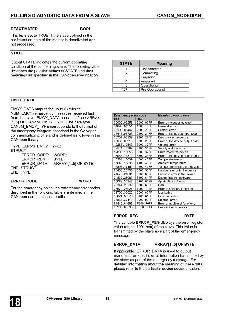
POLLING DIAGNOSTIC DATA FROM A SLAVE CANOM_NODEDIAG
CANopen_S90 Library 18 907 AC 1131/Issued: 05.0318
DEACTIVATED BOOLThis bit is set to TRUE, if the slave defined in theconfiguration data of the master is deactivated andnot processed.
STATE
Output STATE indicates the current operatingcondition of the concerning slave. The following tabledescribes the possible values of STATE and theirmeanings as specified in the CANopen specification.
STATE Meaning1 Disconnected2 Connecting3 Preparing4 Prepared5 Operational
127 Pre-Operational
EMCY_DATA
EMCY_DATA outputs the up to 5 (refer toNUM_EMCY) emergency messages received lastfrom the slave. EMCY_DATA consists of one ARRAY[1..5] OF CANoM_EMCY_TYPE. The data typeCANoM_EMCY_TYPE corresponds to the format ofthe emergency telegram described in the CANopencommunication profile and is defined as follows in theCANopen library:
TYPE CANoM_EMCY_TYPE:STRUCT
ERROR_CODE: WORD;ERROR_REG: BYTE;ERROR_DATA: ARRAY [1..5] OF BYTE;
END_STRUCTEND_TYPE
ERROR_CODE WORDFor the emergency object the emergency error codesdescribed in the following table are defined in theCANopen communication profile.
Emergency error code Meaning / error causedec Hex00000..00255 0000..00FF Error on reset or no error04096..04351 1000..10FF General error08192..08447 2000..20FF Current error08448..08703 2100..21FF Error at the device input side08704..08959 2200..22FF Error inside the device08960..09215 2300..23FF Error at the device output side12288..12543 3000..30FF Voltage error12544..12799 3100..31FF Supply voltage error12800..13055 3200..32FF Error inside the device13056..13311 3300..33FF Error at the device output side16384..16639 4000..40FF Temperature error16640..16895 4100..41FF Ambient temperature16896..17151 4200..42FF Temperature inside the device20480..20735 5000..50FF Hardware error in the device24576..24831 6000..60FF Software error in the device24832..25087 6100..61FF Device-internal software25088..25343 6200..62FF Application software25344..25599 6300..63FF Data28672..28927 7000..70FF Error in additional modules32768..33023 8000..80FF Monitoring33024..33279 8100..81FF Communication36864..37119 9000..90FF External error61440..61695 F000..F0FF Error of additional functions65280..65535 FF00..FFFF Device-specific errors
ERROR_REG BYTEThe variable ERROR_REG displays the error registervalue (object 1001 hex) of the slave. This value istransmitted by the slave as a part of the emergencymessage.
ERROR_DATA ARRAY[1..5] OF BYTEIf applicable, ERROR_DATA is used to outputmanufacturer-specific error information transmitted bythe slave as part of the emergency message. Fordetailed information about the meaning of these dataplease refer to the particular device documentation.

RESETTING THE COUPLER'S ERROR INDICATIONS CANOM_RES_ERR
907 AC 1131/Issued: 05.03 19 CANopen_S90 Library 18
RESETTING THE COUPLER'S ERROR INDICATIONS CANOM_RES_ERRThe block CANoM_RES_ERR canbe used to reset various internalerror indications and counters ofthe coupler.
Block dataAvailable as of PLC runtime system: V5.0 Remark:Included in library: CANopen_S90_V50.LIB
Block typeFunction block with historical values
ParametersInstance CANoM_RES_ERR Instance nameEN BOOL Enabling of the block processingCONO BYTE Slot (module number) of the couplerDONE BOOL Ready message of the blockERR WORD Error message
DescriptionUsing the block CANoM_RES_ERR the followinginternal error indications and counters of the coupleroutput via the block CANoM_STAT can be reset:
- STATE_BITS.EVENT- STATE_BITS.TIMEOUT- BUS_ERR- BUS_OFF- TO_ERR- RX_OVF
For explanations of the error indications please referto the description of the block CANoM_STAT.
The reset is initiated by a FALSE -> TRUE edge atinput EN.
EN BOOL
If a FALSE → TRUE edge is applied to input EN it isfirst checked whether the value at input CONO isvalid. If the value is valid, a corresponding requestmessage is sent to the coupler. While this requestmessage is processed, output DONE is set toFALSE. If the value at input CONO is not valid, therequest is not processed. In this case the error isimmediately indicated at output ERR and thecompletion of the processing is indicated byDONE = TRUE.
While the request is processed, state changes atinput EN are recognized but not evaluated.
CONO BYTEAt input CONO the slot (module number) of thecoupler is applied which should process the request.The module number depends on the PLC category.
R018X CONO = 1R01X8 CONO = 2
DONE BOOLOutput DONE reflects the state of the requestprocessing. If the block is trigged by aFALSE → TRUE edge at input EN, DONE is set toFALSE in order to indicate that the requestprocessing is running. If processing of the task iscompleted, DONE is set to TRUE for one cycleperiod.
If DONE = TRUE and ERR = 0, the error indicationscould be reset successfully. If ERR is not 0, an erroroccurred.

RESETTING THE COUPLER'S ERROR INDICATIONS CANOM_RES_ERR
CANopen_S90 Library 20 907 AC 1131/Issued: 05.0318
ERR WORDAt output ERR an error identifier is applied for a periodof one cycle if an invalid value was applied to inputCONO or if an error occurred during processing of thejob. ERR has always to be considered together with theoutput DONE. The value applied at ERR is only valid ifDONE = TRUE. The error message encoding at outputERR applies to all CANopen blocks and is explained atthe beginning of the library description.
Function call in ILCAL RES_ERR(EN := RES_ERR_EN,CONO := RES_ERR_CONO)
LD RES_ERR.DONEST RES_ERR_DONELD RES_ERR.ERRST RES_ERR_ERR
Note:In IL, the function call has to be performed in oneline.
Function call in STRES_ERR(EN := RES_ERR _EN,CONO := RES_ERR _CONO);RES_ERR_DONE := RES_ERR.DONE;RES_ERR_ERR := RES_ERR.ERR;
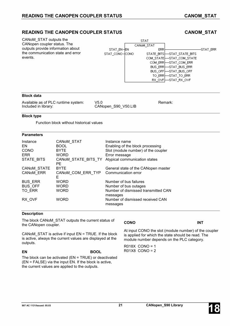
READING THE CANOPEN COUPLER STATUS CANOM_STAT
907 AC 1131/Issued: 05.03 21 CANopen_S90 Library 18
READING THE CANOPEN COUPLER STATUS CANOM_STATCANoM_STAT outputs theCANopen coupler status. Theoutputs provide information aboutthe communication state and errorevents.
Block dataAvailable as of PLC runtime system: V5.0 Remark:Included in library: CANopen_S90_V50.LIB
Block typeFunction block without historical values
ParametersInstance CANoM_STAT Instance nameEN BOOL Enabling of the block processingCONO BYTE Slot (module number) of the couplerERR WORD Error messageSTATE_BITS CANoM_STATE_BITS_TY
PEAtypical communication states
CANoM_STATE BYTE General state of the CANopen masterCANoM_ERR CANoM_COM_ERR_TYP
ECommunication error
BUS_ERR WORD Number of bus failuresBUS_OFF WORD Number of bus outagesTO_ERR WORD Number of dismissed transmitted CAN
messagesRX_OVF WORD Number of dismissed received CAN
messages
DescriptionThe block CANoM_STAT outputs the current status ofthe CANopen coupler.
CANoM_STAT is active if input EN = TRUE. If the blockis active, always the current values are displayed at theoutputs.
EN BOOLThe block can be activated (EN = TRUE) or deactivated(EN = FALSE) via the input EN. If the block is active,the current values are applied to the outputs.
CONO INT
At input CONO the slot (module number) of the coupleris applied for which the state should be read. Themodule number depends on the PLC category.
R018X CONO = 1R01X8 CONO = 2
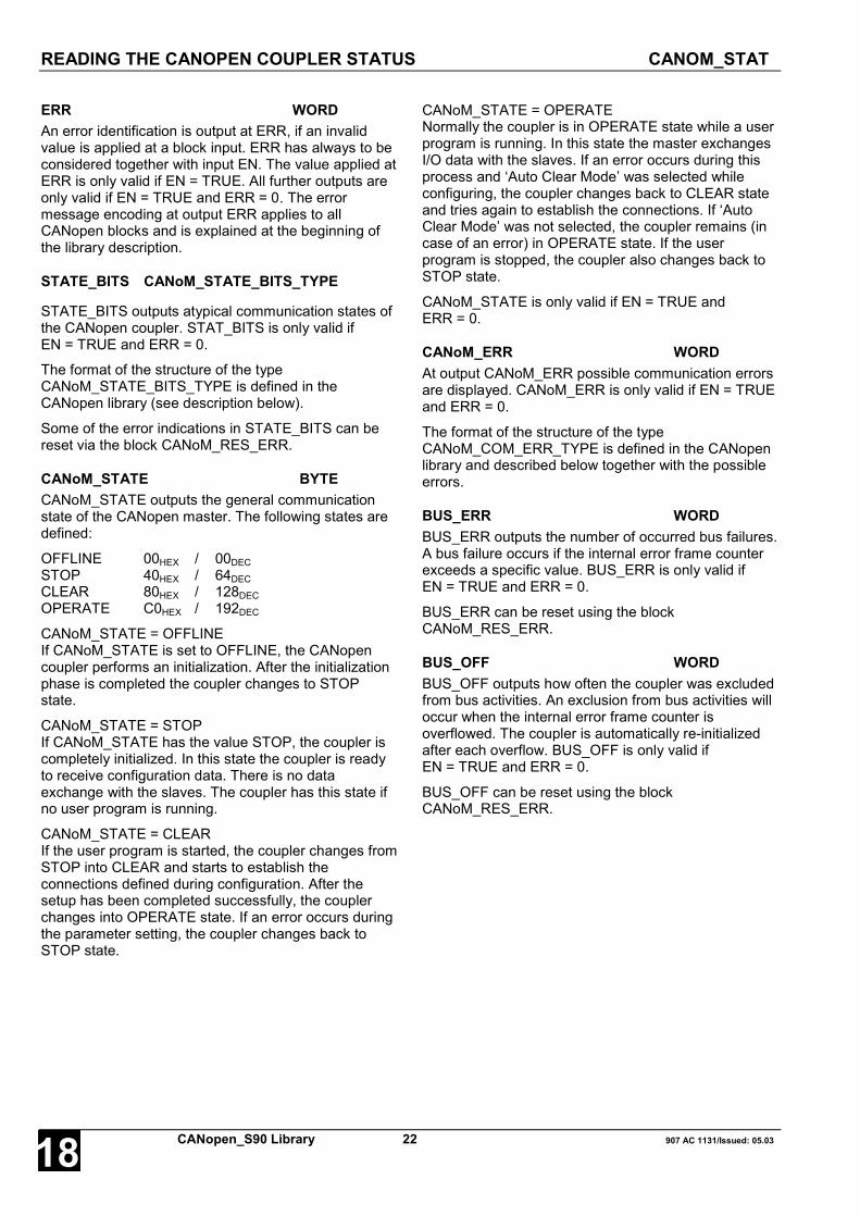
READING THE CANOPEN COUPLER STATUS CANOM_STAT
CANopen_S90 Library 22 907 AC 1131/Issued: 05.0318
ERR WORDAn error identification is output at ERR, if an invalidvalue is applied at a block input. ERR has always to beconsidered together with input EN. The value applied atERR is only valid if EN = TRUE. All further outputs areonly valid if EN = TRUE and ERR = 0. The errormessage encoding at output ERR applies to allCANopen blocks and is explained at the beginning ofthe library description.
STATE_BITS CANoM_STATE_BITS_TYPE
STATE_BITS outputs atypical communication states ofthe CANopen coupler. STAT_BITS is only valid ifEN = TRUE and ERR = 0.
The format of the structure of the typeCANoM_STATE_BITS_TYPE is defined in theCANopen library (see description below).
Some of the error indications in STATE_BITS can bereset via the block CANoM_RES_ERR.
CANoM_STATE BYTECANoM_STATE outputs the general communicationstate of the CANopen master. The following states aredefined:
OFFLINE 00HEX / 00DECSTOP 40HEX / 64DECCLEAR 80HEX / 128DECOPERATE C0HEX / 192DEC
CANoM_STATE = OFFLINEIf CANoM_STATE is set to OFFLINE, the CANopencoupler performs an initialization. After the initializationphase is completed the coupler changes to STOPstate.
CANoM_STATE = STOPIf CANoM_STATE has the value STOP, the coupler iscompletely initialized. In this state the coupler is readyto receive configuration data. There is no dataexchange with the slaves. The coupler has this state ifno user program is running.
CANoM_STATE = CLEARIf the user program is started, the coupler changes fromSTOP into CLEAR and starts to establish theconnections defined during configuration. After thesetup has been completed successfully, the couplerchanges into OPERATE state. If an error occurs duringthe parameter setting, the coupler changes back toSTOP state.
CANoM_STATE = OPERATENormally the coupler is in OPERATE state while a userprogram is running. In this state the master exchangesI/O data with the slaves. If an error occurs during thisprocess and ‘Auto Clear Mode’ was selected whileconfiguring, the coupler changes back to CLEAR stateand tries again to establish the connections. If ‘AutoClear Mode’ was not selected, the coupler remains (incase of an error) in OPERATE state. If the userprogram is stopped, the coupler also changes back toSTOP state.
CANoM_STATE is only valid if EN = TRUE andERR = 0.
CANoM_ERR WORDAt output CANoM_ERR possible communication errorsare displayed. CANoM_ERR is only valid if EN = TRUEand ERR = 0.
The format of the structure of the typeCANoM_COM_ERR_TYPE is defined in the CANopenlibrary and described below together with the possibleerrors.
BUS_ERR WORDBUS_ERR outputs the number of occurred bus failures.A bus failure occurs if the internal error frame counterexceeds a specific value. BUS_ERR is only valid ifEN = TRUE and ERR = 0.
BUS_ERR can be reset using the blockCANoM_RES_ERR.
BUS_OFF WORDBUS_OFF outputs how often the coupler was excludedfrom bus activities. An exclusion from bus activities willoccur when the internal error frame counter isoverflowed. The coupler is automatically re-initializedafter each overflow. BUS_OFF is only valid ifEN = TRUE and ERR = 0.
BUS_OFF can be reset using the blockCANoM_RES_ERR.

READING THE CANOPEN COUPLER STATUS CANOM_STAT
907 AC 1131/Issued: 05.03 23 CANopen_S90 Library 18
TO_ERR WORDTO_ERR outputs how many telegrams could not betransmitted successfully. Transmission of a telegram isconsidered as failed, if it could not be transmitted within20 ms, for instance because the communication partnercould not be contacted via the bus. TO_ERR is onlyvalid if EN = TRUE and ERR = 0.
TO_ERR can be reset using the blockCANoM_RES_ERR.
RX_OVF WORDRX_OVF outputs how many received telegrams weredismissed because they could not be processedsuccessfully due to an overload of the CAN chip.RX_OVF is only valid if EN = TRUE and ERR = 0.
RX_OVF can be reset using the blockCANoM_RES_ERR.
Function call in ILCAL STAT(EN := STAT_EN,CONO := STAT_CONO)
LD STAT.ERRST STAT_ERRLD STAT.STATE_BITSST STAT_STATE_BITSLD STAT.CANoM_STATEST STAT_CANoM_STATELD STAT.CANoM_ERRST STAT_CANoM_ERRLD STAT.BUS_ERRST STAT_BUS_ERRLD STAT.BUS_OFFST STAT_BUS_OFFLD STAT.TO_ERRST STAT_TO_ERRLD STAT.RX_OVFST STAT_RX_OVF
Note:In IL, the function call has to be performed in oneline.
Function call in STSTAT(EN := STAT_EN,CONO := STAT_CONO);
STAT_ERR := STAT.ERR;STAT_STATE_BITS := STAT.STATE_BITS;STAT_CANoM_STATE := STAT.CANoM_STATE;STAT_CANoM_ERR := STAT.CANoM_ERR;STAT_BUS_ERR := STAT.BUS_ERR;STAT_BUS_OFF := STAT.BUS_OFF;STAT_TO_ERR := STAT.TO_ERR;STAT_RX_OVF := STAT.RX_OVF;
STATE_BITS CANoM_STATE_BITS_TYPEThe structure STATE_BITS consists of six booleanvariables which display different communicationstates. Within the CANopen library the data typeCANoM_STATE_BITS_TYPE is declared as follows:
TYPE CANoM_STATE_BITS_TYPE:STRUCT
CTRL: BOOL;AUTO_CLR: BOOL;NO_EXCH: BOOL;FATAL: BOOL;EVENT: BOOL;TIMEOUT: BOOL;
END_STRUCTEND_TYPE
CTRL BOOLIf this bit is set to TRUE, a parameter setting erroroccurred. In normal operation CTRL should beFALSE. If this is not the case, the parameter andconfiguration data have to be checked.
AUTO_CLR BOOLIf AUTO_CLR is set to TRUE, the coupler hasstopped the data exchange with all slaves due tocommunication errors and has changed back toCLEAR state (see CANoM_STATE).

READING THE CANOPEN COUPLER STATUS CANOM_STAT
CANopen_S90 Library 24 907 AC 1131/Issued: 05.0318
NO_EXCH BOOLThis bit is set to TRUE, if exchanging process datawith one or several slaves is not possible. The errorcause can be found in the configuration data as wellas in the slaves.
FATAL BOOLIf FATAL is set to TRUE, no communication viaCANopen is possible due to a fatal internal error.
EVENT BOOLEVENT is set to TRUE if transmission errors aredetected by the coupler. The number of occurredtransmission errors is displayed at the correspondingoutputs BUS_ERR and BUS_OFF. If the EVENT bitis set to TRUE, reset is only possible via the blockCANoM_RES_ERR.
TIMEOUT BOOLIf TIMEOUT is set to TRUE, transmission of at leastone telegram failed. Transmission of this telegramwas aborted and its content is lost. TIMEOUT =TRUE is an indication that the communication partnercould not be contacted via the bus. The number offailed transmissions is displayed at output TO_ERR.If the TIMEOUT bit is set to TRUE, reset is onlypossible via the block CANoM_RES_ERR.
CANoM_ERR CANoM_COM_ERR_TYPECommunication errors can be located precisely via CANoM_ERR. The output CANoM_ERR is represented as astructure of the type CANoM_COM_ERR_TYPE. Within the CANopen library this data type is declared as follows:
TYPE CANoM_COM_ERR_TYPE:STRUCT
ADDRESS: BYTE;EVENT: BYTE;
END_STRUCTEND_TYPE
ADDRESS BYTEIn case of an error, ADDRESS contains the node address of the faulty subscriber. If ADDRESS has the value 255,the error is located in the coupler itself.
ADDRESS = 255 Coupler error
EVENT Meaning Error source Cause / Remedy
52 Unknown process datahandshake mode Configuration Contact Support
56 Invalid data transmission rate Configuration Contact Support
60 Duplicate node addressconfigured
Configuration/ anotherdevice
Check node addresses of all devicesspecified in configuration data
210 No configuration data Configuration/Coupler Load configuration data into coupler
212 Error while reading database Configuration/Coupler
Load configuration data into coupleronce again. Contact Support.
220 Watchdog error Basic unit Contact Support

READING THE CANOPEN COUPLER STATUS CANOM_STAT
907 AC 1131/Issued: 05.03 25 CANopen_S90 Library 18
ADDRESS <> 255 Error at subscriber with node address ADDRESS
EVENT Meaning Error source Cause / Remedy
30 Slave monitoring timeout Slave Check connection and node address ofthe slave
31 Slave aborted operational mode Slave Reset slave
32 Sequence error in node guardingprotocol Slave Reset slave
33 No response to configuredremote frame PDO Slave Check whether the slave supports
remote frames
34 No slave response duringconfiguration Slave Check that the slave is connected and
ready for operation
35Actual device profile of the slavediffers from the configured deviceprofile
Configuration Check the profile supported by theslave
36Actual device type of the slavediffers from the configured devicetype
Configuration Check the services supported by theslave
37 Unknown SDO responsereceived Slave Slave does not meet the specifications
of the CiA protocol
38 Length indicator of a receivedSDO response is not 8 Slave Slave does not meet the specifications
of the CiA protocol
39 Slave is not processed. It is inthe STOP state.
Configuration/Coupler Deactivate the 'Auto Clear Mode'
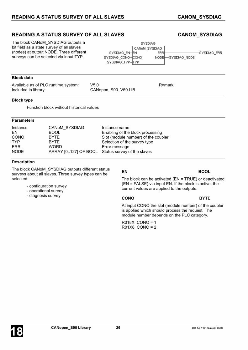
READING A STATUS SURVEY OF ALL SLAVES CANOM_SYSDIAG
CANopen_S90 Library 26 907 AC 1131/Issued: 05.0318
READING A STATUS SURVEY OF ALL SLAVES CANOM_SYSDIAGThe block CANoM_SYSDIAG outputs abit field as a state survey of all slaves(nodes) at output NODE. Three differentsurveys can be selected via input TYP.
Block dataAvailable as of PLC runtime system: V5.0 Remark:Included in library: CANopen_S90_V50.LIB
Block typeFunction block without historical values
ParametersInstance CANoM_SYSDIAG Instance nameEN BOOL Enabling of the block processingCONO BYTE Slot (module number) of the couplerTYP BYTE Selection of the survey typeERR WORD Error messageNODE ARRAY [0..127] OF BOOL Status survey of the slaves
DescriptionThe block CANoM_SYSDIAG outputs different statussurveys about all slaves. Three survey types can beselected:
- configuration survey- operational survey- diagnosis survey
EN BOOLThe block can be activated (EN = TRUE) or deactivated(EN = FALSE) via input EN. If the block is active, thecurrent values are applied to the outputs.
CONO BYTEAt input CONO the slot (module number) of the coupleris applied which should process the request. Themodule number depends on the PLC category.
R018X CONO = 1R01X8 CONO = 2

READING A STATUS SURVEY OF ALL SLAVES CANOM_SYSDIAG
907 AC 1131/Issued: 05.03 27 CANopen_S90 Library 18
TYP BYTEThe input TYP is used to select which status surveyshould be displayed at output NODE.
TYP = 1 configuration surveyOutput NODE displays which slaves were successfullyconnected to the master (TRUE). Please note that themaster establishes only a connection to those slaveswhich were announced to the master when defining theconfiguration data.
TYP = 2 operational surveyOutput NODE displays which slaves are error-free andin operation. A slave can only be announced asoperational if it has been configured in the master. Theoperational survey can only be requested if the coupleris in OPERATE state.
TYP = 3 diagnosis surveyOutput NODE indicates which slaves report adiagnosis. The diagnosis survey can only be requestedif the coupler is in OPERATE state.
ERR WORD
An error identification is applied at output ERR if aninvalid value is applied at an input. ERR has always tobe considered together with input EN. The valueapplied at ERR is only valid if EN = TRUE. All furtheroutputs are only valid if EN = TRUE and ERR = 0. The
error message encoding at output ERR applies to allCANopen blocks and is explained at the beginning ofthe library description.
NODE ARRAY [0..127] OF BOOLAt output NODE the status survey is output as a bitfield. Every bit within this field represents a slave. Withthis, the index corresponds to the slave's node address.If a bit is set to TRUE, the state selected using TYPapplies to the corresponding slave.
If e.g. TYP = 1 is selected and NODE[2] = TRUE, theslave with this node address was successfullyconfigured by the master and is in operation. IfNODE[2] = FALSE, the configuration of the specificslave has not yet been completed or the slave is notpart of the master's configuration data.
If TYP = 3, e.g. NODE[2] = TRUE means that the slavewith the node address 2 has received an emergencymessage or that the diagnostic indication of the slavehas changed. The detailed diagnosis can then berequested using the block CANoM_NODEDIAG.
The bit field output at NODE is only valid if EN = TRUEand ERR = 0.
Function call in ILCAL SYSDIAG
(EN := SYSDIAG_EN,CONO := SYSDIAG_CONO,TYP := SYSDIAG_TYP)
LD SYSDIAG.ERRST SYSDIAG_ERRLD SYSDIAG.NODEST SYSDIAG_NODE
Note:In IL, the function call has to be performed in oneline.
Function call in STSYSDIAG
(EN := SYSDIAG_EN,CONO := SYSDIAG_CONO,TYP := SYSDIAG_TYP);
SYSDIAG_ERR := SYSDIAG.ERR;SYSDIAG_NODE := SYSDIAG.NODE;
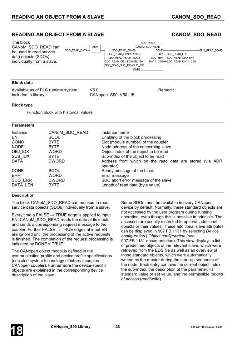
READING AN OBJECT FROM A SLAVE CANOM_SDO_READ
CANopen_S90 Library 28 907 AC 1131/Issued: 05.0318
READING AN OBJECT FROM A SLAVE CANOM_SDO_READThe blockCANoM_SDO_READ canbe used to read servicedata objects (SDOs)individually from a slave.
Block dataAvailable as of PLC runtime system: V5.0 Remark:Included in library: CANopen_S90_V50.LIB
Block typeFunction block with historical values
ParametersInstance CANoM_SDO_READ Instance nameEN BOOL Enabling of the block processingCONO BYTE Slot (module number) of the couplerNODE BYTE Node address of the concerning slaveOBJ_IDX WORD Object index of the object to be readSUB_IDX BYTE Sub-index of the object to be readDATA DWORD Address from which on the read data are stored (via ADR
operator)DONE BOOL Ready message of the blockERR WORD Error messageSDO_ERR DWORD SDO abort error message of the slaveDATA_LEN BYTE Length of read data (byte value)
DescriptionThe block CANoM_SDO_READ can be used to readservice data objects (SDOs) individually from a slave.
Every time a FALSE → TRUE edge is applied to inputEN, CANoM_SDO_READ reads the data at its inputsand sends a corresponding request message to thecoupler. Further FALSE → TRUE edges at input ENare ignored until the processing of the active requestsis finished. The completion of the request processing isindicated by DONE = TRUE.
The CANopen object model is defined in thecommunication profile and device profile specifications(see also system technology of internal couplers -CANopen coupler). Furthermore the device-specificobjects are explained in the corresponding devicedescription of the slave.
Some SDOs must be available in every CANopendevice by default. Normally, these standard objects arenot accessed by the user program during runningoperation, even though this is possible in principle. Theaccesses are usually restricted to optional additionalobjects or their values. These additional slave attributescan be displayed in 907 FB 1131 by selecting Deviceconfiguration | Object configuration (see907 FB 1131 documentation). This view displays a listof predefined objects of the relevant slave, which wereretrieved from the EDS file as well as an overview ofthose standard objects, which were automaticallywritten by the master during the start-up sequence ofthe node. Each entry contains the current object index,the sub-index, the description of the parameter, itsstandard value or set value, and the permissible modesof access (read/write).

READING AN OBJECT FROM A SLAVE CANOM_SDO_READ
907 AC 1131/Issued: 05.03 29 CANopen_S90 Library 18
When using a function block of theCANoM_SDO_READ type, this information can beused to select the desired OBJ_IDX and SUB_IDX.
EN BOOLIf a FALSE → TRUE edge is applied to input EN, allfurther inputs are read in.
If the input values are valid, a corresponding requestmessage is sent to the coupler. While this requestmessage is processed, the output DONE is set toFALSE. If at least one input value is invalid, an error isindicated at output ERR. Additionally the termination ofthe request processing is indicated by DONE = TRUE.
While the request is processed, state changes at inputEN are recognized but not evaluated. As the blockexecution requires a bus access, the data are availablein the next cycle at the earliest after activating theblock.
CONO BYTEAt input CONO the slot (module number) of the coupleris applied which should process the request. Themodule number depends on the PLC category.
R018X CONO = 1R01X8 CONO = 2
NODE BYTE
At input NODE the node address of the slave isspecified the object value of which is to be requested.
OBJ_IDX WORDAt input OBJ_IDX , the object index of the object to beread in the slave object directory is specified (compareto Obj. Idx. entry in Object configuration list in907 FB 1131).
SUB_IDX WORDAt input SUB_IDX , the sub-index of the object to beread in the slave object directory is specified (compareto Sub. Idx. entry in Object configuration list in907 FB 1131).
DATA DWORD
The address of the variable to which the receivedobject data are to be written is specified at input DATAvia the ADR operator. According to the object formatapplied at input DATA, a variable of any data format
can be specified via the ADR operator. It is absolutelynecessary that the size of the variables (e.g. ARRAY) issufficient to hold the amount of the read data. Thereceived data are only valid if DONE = TRUE, ERR = 0and DATA_LEN > 0.
DONE BOOLThe output DONE reflects the state of the requestprocessing. If the block is trigged by a FALSE → TRUEedge at input EN, DONE is set to FALSE in order toindicate that the request processing is running. Ifprocessing of the task is completed, DONE is set toTRUE for one cycle period.
The values applied at the block outputs are only valid ifDONE = TRUE.
ERR WORDAt the output ERR an error identifier is applied for aperiod of one cycle if an invalid value was applied to aninput or if an error occurred during processing of thejob. ERR has always to be considered together with theoutput DONE. The value applied at ERR is only valid ifDONE = TRUE. The error message encoding at outputERR applies to all CANopen blocks and is explained atthe beginning of the library description.
If the slave answered the SDO message with an abortmessage, this is displayed by ERR = 2403 hex (9219dec). In many cases this is the result of in an invalidobject index or sub-index or of missing access rights. Inthis case, the error code transmitted by the slave isadditionally output at SDO_ERR.
SDO_ERR DWORDIf the slave answered the SDO message with an abortmessage, the transmitted error code (refer to CANopencommunication profile specification) is output atSDO_ERR. The value applied at SDO_ERR is onlyvalid if DONE = TRUE and ERR = 2403 hex (9219dec).
DATA_LEN BYTEThe length of the received object data (byte value) isoutput at DATA_LEN after the procedure has beencompleted successfully. As the block executionrequires a bus access, the data are available in thenext cycle at the earliest after activating the block. Thevalue of this input is only valid for DONE = TRUE andERR = 0.

READING AN OBJECT FROM A SLAVE CANOM_SDO_READ
CANopen_S90 Library 30 907 AC 1131/Issued: 05.0318
Function call in ILLD SDO_READ_DATAADRST ADR_SDO_READ_DATA
CAL SDO_READ(EN := SDO_READ_EN,CONO := SDO_READ_CONO,NODE := SDO_READ_NODE,OBJ_IDX := SDO_READ_OBJ_IDX,SUB_IDX := SDO_READ_SUB_IDX,DATA := ADR_SDO_READ_DATA)
LD SDO_READ.DONEST SDO_READ_DONELD SDO_READ.ERRST SDO_READ_ERRLD SDO_READ.SDO_ERRST SDO_READ_SDO_ERRLD SDO_READ.DATA_LENST SDO_READ_DATA_LEN
Note:In IL, the function call has to be performed in oneline.
Function call in STSDO_READ(EN := SDO_READ_EN,CONO := SDO_READ_CONO,NODE := SDO_READ_NODE,OBJ_IDX := SDO_READ_OBJ_IDX,SUB_IDX := SDO_READ_SUB_IDX,DATA := ADR(SDO_READ_DATA));
SDO_READ_DONE := SDO_READ.DONE;SDO_READ_ERR := SDO_READ.ERR;SDO_READ_SDO_ERR := SDO_READ.SDO_ERR;SDO_READ_DATA_LEN:= SDO_READ.DATA_LEN;

WRITING AN OBJECT TO A SLAVE CANOM_SDO_WRITE
907 AC 1131/Issued: 05.03 31 CANopen_S90 Library 18
WRITING AN OBJECT TO A SLAVE CANOM_SDO_WRITEThe blockCANoM_SDO_WRITE can beused to writeservice dataobjects (SDOs)individually to aslave.
Block dataAvailable as of PLC runtime system: V5.0 Remark:Included in library: CANopen_S90_V50.LIB
Block typeFunction block with historical values
ParametersInstance CANoM_SDO_WRITE Instance nameEN BOOL Enabling of the block processingCONO BYTE Slot (module number) of the couplerNODE BYTE Node address of the relevant slaveOBJ_IDX WORD Object index of the object to be writtenSUB_IDX BYTE Sub-index of the object to be writtenDATA DWORD Address from which on the data to be written are stored (via ADR
operator)DATA_LEN BYTE Length of data to be written (byte value)DONE BOOL Ready message of the blockERR WORD Error messageSDO_ERR DWORD SDO abort error message of the slave
DescriptionThe block CANoM_SDO_WRITE can be used to writeservice data objects (SDOs) individually to a slave.
Every time a FALSE → TRUE edge is applied to inputEN, CANoM_SDO_WRITE reads the data at its inputsand sends a corresponding request message to thecoupler. Further FALSE → TRUE edges at input ENare ignored until the processing of the active requestsis finished. The completion of the request processing isindicated by DONE = TRUE.
The CANopen object model is defined in thecommunication profile and device profile specifications(see also system technology of internal couplers -CANopen coupler). Furthermore the device-specificobjects are explained in the corresponding devicedescription of the slave.
Some SDOs must be available in every CANopendevice by default. Normally, these standard objects arenot accessed by the user program during runningoperation, even though this is possible in principle. Theaccesses are usually restricted to optional additional
objects or their values. These additional slave attributescan be displayed in 907 FB 1131 by selecting Deviceconfiguration | Object configuration (see907 FB 1131 documentation). This view displays a listof predefined objects of the relevant slave, which wereretrieved from the EDS file as well as an overview ofthose standard objects, which were automaticallywritten by the master during the start-up sequence ofthe node. Each entry contains the current object index,the sub-index, the description of the parameter, itsstandard value or set value, and the permissible modesof access (read/write).When using a function block of theCANoM_SDO_WRITE type, this information can beused to select the desired OBJ_IDX and SUB_IDX.

WRITING AN OBJECT TO A SLAVE CANOM_SDO_WRITE
CANopen_S90 Library 32 907 AC 1131/Issued: 05.0318
EN BOOL
If a FALSE → TRUE edge is applied to input EN, allfurther inputs are read in.
If the input values are valid, a corresponding requestmessage is sent to the coupler. While this requestmessage is processed, the output DONE is set toFALSE. If at least one input value is invalid, an error isindicated at output ERR. Additionally the termination ofthe request processing is indicated by DONE = TRUE.
While the request is processed, state changes at inputEN are recognized but not evaluated.
CONO BYTE
At input CONO the slot (module number) of the coupleris applied which should process the request. Themodule number depends on the PLC category.
R018X CONO = 1R01X8 CONO = 2
NODE BYTEAt input NODE the node address of the slave isspecified to which an object value is to be written.
OBJ_IDX WORDAt input OBJ_IDX, the object index of the object to bewritten to the slave object directory is specified(compare to Obj. Idx. entry in Object configuration list in907 FB 1131).
SUB_IDX BYTEAt input SUB_IDX, the sub-index of the object to bewritten to the slave object directory is specified(compare to Sub. Idx. entry in Object configuration listin 907 FB 1131).
DATA DWORDThe address of the variable, which contains the objectdata to be written, is specified at the input DATA via theADR operator. According to the object format applied atinput DATA, a variable of any data format can bespecified via the ADR operator.
DATA_LEN BYTEAt input DATA_LEN, the length of the data to betransmitted stored in the variable at address DATA isspecified as a byte value. This value must match thesize of the object to be written. The maximum datalength is 247 bytes.
DONE BOOLThe output DONE reflects the state of the requestprocessing. If the block is trigged by a FALSE → TRUEedge at input EN, DONE is set to FALSE in order toindicate that the request processing is running. Ifprocessing of the task is completed, DONE is set toTRUE for one cycle period.
The values applied at the block outputs are only valid ifDONE = TRUE.
ERR WORDAt output ERR an error identifier is applied for a periodof one cycle if an invalid value was applied to an inputor if an error occurred during processing of the job.ERR has always to be considered together with theoutput DONE. The value applied at ERR is only valid ifDONE = TRUE. The error message encoding at outputERR applies to all CANopen blocks and is explained atthe beginning of the library description.
If the slave answered the SDO message with an abortmessage, this is displayed by ERR = 2403 hex (9219dec). In many cases this is the result of in an invalidobject index or sub-index or of missing access rights. Inthis case, the error code transmitted by the slave isadditionally output at SDO_ERR.
SDO_ERR DWORDIf the slave answered the SDO message with an abortmessage, the transmitted error code (refer to CANopencommunication profile specification) is output atSDO_ERR. The value applied at SDO_ERR is onlyvalid if DONE = TRUE and ERR = 2403 hex (9219dec).
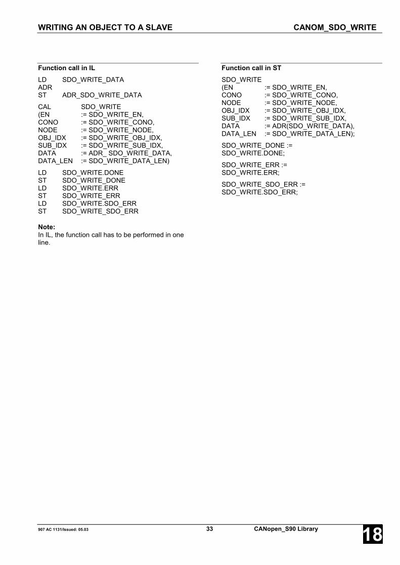
WRITING AN OBJECT TO A SLAVE CANOM_SDO_WRITE
907 AC 1131/Issued: 05.03 33 CANopen_S90 Library 18
Function call in ILLD SDO_WRITE_DATAADRST ADR_SDO_WRITE_DATA
CAL SDO_WRITE(EN := SDO_WRITE_EN,CONO := SDO_WRITE_CONO,NODE := SDO_WRITE_NODE,OBJ_IDX := SDO_WRITE_OBJ_IDX,SUB_IDX := SDO_WRITE_SUB_IDX,DATA := ADR_ SDO_WRITE_DATA,DATA_LEN := SDO_WRITE_DATA_LEN)
LD SDO_WRITE.DONEST SDO_WRITE_DONELD SDO_WRITE.ERRST SDO_WRITE_ERRLD SDO_WRITE.SDO_ERRST SDO_WRITE_SDO_ERR
Note:In IL, the function call has to be performed in oneline.
Function call in STSDO_WRITE(EN := SDO_WRITE_EN,CONO := SDO_WRITE_CONO,NODE := SDO_WRITE_NODE,OBJ_IDX := SDO_WRITE_OBJ_IDX,SUB_IDX := SDO_WRITE_SUB_IDX,DATA := ADR(SDO_WRITE_DATA),DATA_LEN := SDO_WRITE_DATA_LEN);
SDO_WRITE_DONE :=SDO_WRITE.DONE;
SDO_WRITE_ERR :=SDO_WRITE.ERR;
SDO_WRITE_SDO_ERR :=SDO_WRITE.SDO_ERR;
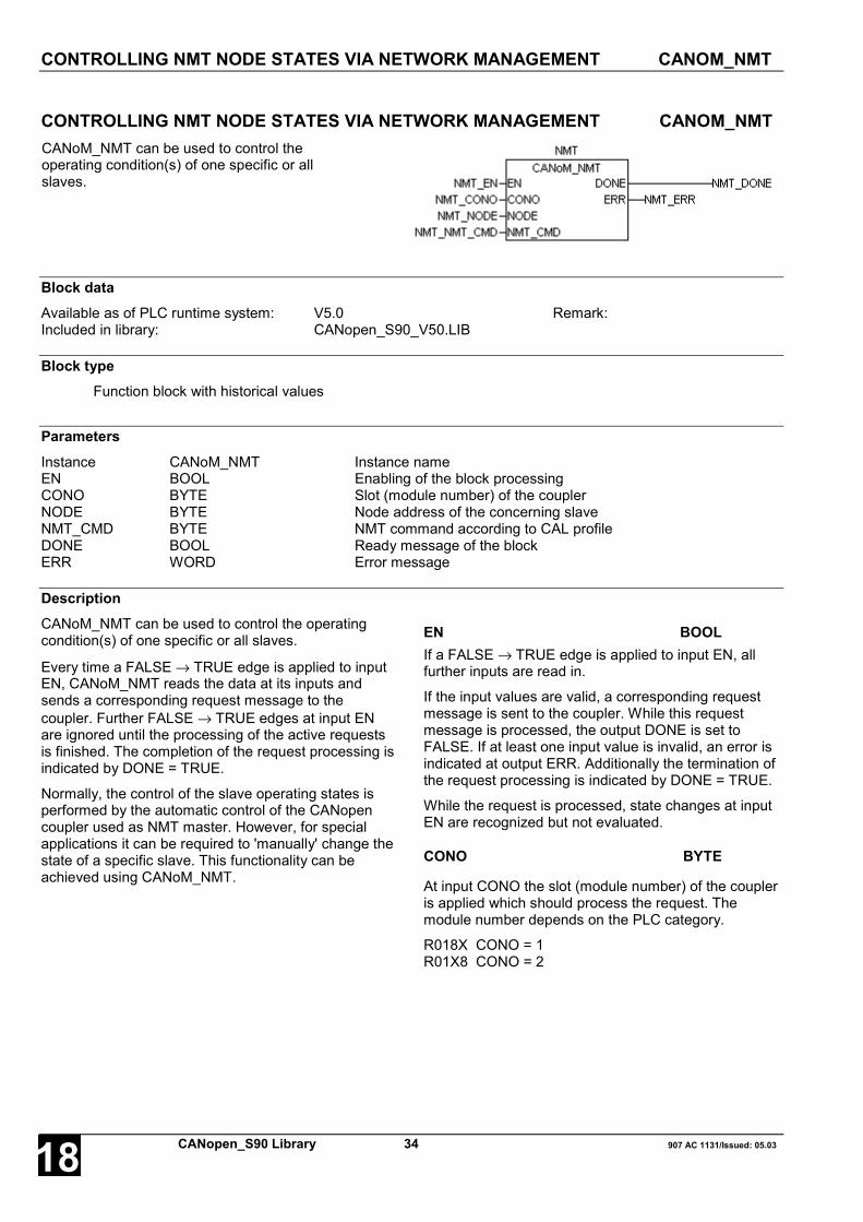
CONTROLLING NMT NODE STATES VIA NETWORK MANAGEMENT CANOM_NMT
CANopen_S90 Library 34 907 AC 1131/Issued: 05.0318
CONTROLLING NMT NODE STATES VIA NETWORK MANAGEMENT CANOM_NMTCANoM_NMT can be used to control theoperating condition(s) of one specific or allslaves.
Block dataAvailable as of PLC runtime system: V5.0 Remark:Included in library: CANopen_S90_V50.LIB
Block typeFunction block with historical values
ParametersInstance CANoM_NMT Instance nameEN BOOL Enabling of the block processingCONO BYTE Slot (module number) of the couplerNODE BYTE Node address of the concerning slaveNMT_CMD BYTE NMT command according to CAL profileDONE BOOL Ready message of the blockERR WORD Error message
DescriptionCANoM_NMT can be used to control the operatingcondition(s) of one specific or all slaves.
Every time a FALSE → TRUE edge is applied to inputEN, CANoM_NMT reads the data at its inputs andsends a corresponding request message to thecoupler. Further FALSE → TRUE edges at input ENare ignored until the processing of the active requestsis finished. The completion of the request processing isindicated by DONE = TRUE.
Normally, the control of the slave operating states isperformed by the automatic control of the CANopencoupler used as NMT master. However, for specialapplications it can be required to 'manually' change thestate of a specific slave. This functionality can beachieved using CANoM_NMT.
EN BOOLIf a FALSE → TRUE edge is applied to input EN, allfurther inputs are read in.
If the input values are valid, a corresponding requestmessage is sent to the coupler. While this requestmessage is processed, the output DONE is set toFALSE. If at least one input value is invalid, an error isindicated at output ERR. Additionally the termination ofthe request processing is indicated by DONE = TRUE.
While the request is processed, state changes at inputEN are recognized but not evaluated.
CONO BYTE
At input CONO the slot (module number) of the coupleris applied which should process the request. Themodule number depends on the PLC category.
R018X CONO = 1R01X8 CONO = 2

CONTROLLING NMT NODE STATES VIA NETWORK MANAGEMENT CANOM_NMT
907 AC 1131/Issued: 05.03 35 CANopen_S90 Library 18
NODE BYTEAt input NODE the node address of the slave isspecified the operating condition of which shall bechanged. By applying a value of 1 to 127 to inputNODE, one specific slave can be called with thecorresponding node address. If NODE = 0 thecommand is sent to all slaves.
NMT_CMD BYTEAt input NMT_CMD, the NMT command to be sent isspecified. The following NMT commands are defined:
NMTcommand
Meaning
1 Start remote node (slave)2 Stop remote node (slave)
128 Enter Pre-Operational: Set slave in pre-operational mode
129 Reset node (slave)130 Reset communication
DONE BOOLThe output DONE reflects the state of the requestprocessing. If the block is trigged by a FALSE → TRUEedge at input EN, DONE is set to FALSE in order toindicate that the request processing is running. If theprocessing of the task is completed, DONE is set toTRUE for one cycle period.
ERR WORDAt output ERR an error identifier is applied for a periodof one cycle if an invalid value was applied to an inputor if an error occurred during processing of the job.ERR has always to be considered together with theoutput DONE. The value applied at ERR is only valid ifDONE = TRUE. The error message encoding at outputERR applies to all CANopen blocks and is explained atthe beginning of the library description.
Function call in ILCAL NMT(EN := NMT_EN,CONO := NMT_CONO,NODE := NMT_NODE,NMT_CMD := NMT_NMT_CMD)
LD SDO_READ.DONEST SDO_READ_DONELD SDO_READ.ERRST SDO_READ_ERR
Note:In IL, the function call has to be performed in oneline.
Function call in STNMT(EN := NMT_EN,CONO := NMT_CONO,NODE := NMT_NODE,NMT_CMD := NMT_NMT_CMD);
NMT_DONE := NMT.DONE;NMT_ERR := NMT.ERR;

GERERATING A GENERAL CAN TELEGRAM HEADERACCORDING TO CAN 2.0 A IDENT_CAN2A_TO_WORD
CANopen_S90 Library 36 907 AC 1131/Issued: 05.0318
GERERATING A GENERAL CAN TELEGRAM HEADERACCORDING TO CAN 2.0 A IDENT_CAN2A_TO_WORDUsing the function IDENT_CAN2A_TO_WORD theindividual elements of a general CAN telegram header canbe put together in the WORD format as it is used by theCAN blocks or the message types.
Block dataAvailable as of PLC runtime system: V5.0 Remark:Included in library: CANopen_S90_V50.LIB
Block typeFunction
ParametersIDENT_ICTW CAN2A_IDENT_TYPE Individual components of the general CAN telegram header, put
together in a structureWORD_ICTW WORD CAN telegram header in WORD format
DescriptionUsing the function IDENT_CAN2A_TO_WORD the individual elements of a CAN telegram header in the generalformat, consisting of the 11 bit identifier, the RTR bit and the data length code (DLC), can be easily put together inthe WORD format as it is used by the CAN blocks or the message types.
Prior to calling the function, first the desired values have to be assigned to the individual components of thestructured input variables. This function has no enable input, it is executed at any time. The output value of thisfunction is structured as follows:
DLC.3 DLC.2 DLC.1 DLC.0 RTR ID.10 ID.9 ID.8 ID.7 ID.6 ID.5 ID.4 ID.3 ID.2 ID.1 ID.015 14 13 12 11 10 9 8 7 6 5 4 3 2 1 0
The inverse functionality of IDENT_CAN2A_TO_WORD is provided by the function WORD_TO_IDENT_CAN2A.
IDENT CAN2A_IDENT_TYPEAt input IDENT a variable of the data type CAN2A_IDENT_TYPE has to be specified. This structure is a summaryof the individual components of the general CAN telegram header.
IDENT_CAN2A_TO_WORD WORDThis function returns the composite general CAN telegram header in the WORD format.
Function call in ILIDENT_CAN2A_TO_WORD IDENT_ICTW
ST WORD_ICTW
Function call in STWORD_ICTW :=IDENT_CAN2A_TO_WORD(IDENT_ICTW);

SPLITTING A GENERAL CAN TELEGRAM HEADERACCORDING TO CAN 2.0 A WORD_TO_IDENT_CAN2A
907 AC 1131/Issued: 05.03 37 CANopen_S90 Library 18
SPLITTING A GENERAL CAN TELEGRAM HEADERACCORDING TO CAN 2.0 A WORD_TO_IDENT_CAN2AUsing the function WORD_TO_IDENT_CAN2A, a compactgeneral CAN telegram header in WORD format (e.g. assupplied by CAN_REC_2A) can be split into its individualcomponents for further processing.
Block dataAvailable as of PLC runtime system: V5.0 Remark:Included in library: CANopen_S90_V50.LIB
Block typeFunction
ParametersWORD_WTIC WORD Compact CAN telegram header in WORD formatIDENT_WTIC CAN2A_IDENT_TYPE Individual components of the general CAN telegram header, put
together in a structure
DescriptionUsing the function WORD_TO_IDENT_CAN2A a compact general CAN telegram header in WORD format (as usedby the CAN blocks or the message types) can be easily split into its individual components 11 bit identifier, RTR bitand data length code (DLC).
This function has no enable input, it is executed at any time. The input value of this function is structured as follows:
DLC.3 DLC.2 DLC.1 DLC.0 RTR ID.10 ID.9 ID.8 ID.7 ID.6 ID.5 ID.4 ID.3 ID.2 ID.1 ID.015 14 13 12 11 10 9 8 7 6 5 4 3 2 1 0
The inverse functionality of WORD_TO_IDENT_CAN2A is provided by the function IDENT_CAN2A_TO_WORD.
IDENT WORDAt input IDENT a variable of the type WORD has to be applied which is structured as described above and e.g.supplied by CAN_REC_2A.
IDENT_CAN2A_TO_WORD CAN2A_IDENT_TYPEThis function returns the individual components of the general CAN telegram header, put together in the data typeCAN2A_IDENT_TYPE. The values of the individual structural elements can then be used for further processing.
Function call in ILWORD_TO_IDENT_CAN2A WORD_WTIC
ST IDENT_WTIC
Function call in STIDENT_WTIC :=WORD_TO_IDENT_CAN2A(WORD_WTIC);

GENERATING A CANOPEN-SPECIFIC CAN TELEGRAMHEADER ACCORDING TO CAN 2.0 A IDENT_CANOPEN_TO_WORD
CANopen_S90 Library 38 907 AC 1131/Issued: 05.0318
GENERATING A CANOPEN-SPECIFIC CAN TELEGRAMHEADER ACCORDING TO CAN 2.0 A IDENT_CANOPEN_TO_WORDUsing the function IDENT_CANopen_TO_WORD the individualelements of a CANopen-specific CAN telegram header can be puttogether in the WORD format as it is used by the CAN blocks or themessage types.
Block dataAvailable as of PLC runtime system: V5.0 Remark:Included in library: CANopen_S90_V50.LIB
Block typeFunction
ParametersIDENT_ICTW CANopen_IDENT_TYPE Individual components of the CANopen-specific CAN telegram
header, put together in a structureWORD_ICTW WORD CAN telegram header in WORD format
DescriptionUsing the function IDENT_CANopen_TO_WORD the individual elements of a CAN telegram header in theCANopen-specific format, consisting of the function code, the node ID, the RTR bit and the data length code (DLC),can be easily put together in the WORD format as it is used by the CAN blocks or the message types.Prior to calling the function, first the desired values have to be assigned to the individual components of thestructured input variables. This function has no enable input, it is executed at any time.The output value of this function is structured as follows. The 11 bit identifier is composed of the node ID and thefunction code.
DLC.3 DLC.2 DLC.1 DLC.0 RTR FCT.3 FCT.2 FCT.1 FCT.0 ID.6 ID.5 ID.4 ID.3 ID.2 ID.1 ID.015 14 13 12 11 10 9 8 7 6 5 4 3 2 1 0
The inverse functionality of IDENT_CANopen_TO_WORD is provided by the functionWORD_TO_IDENT_CANopen.
Note:When generating the header for a CANopen-specific CAN telegram (refer to data typeCANopen_MESSAGE_TYPE) it has to be observed that CANopen already uses 4 bytes of user data. For anadditional transfer of 4 bytes 'real' user data, a data length code (DLC) of 8 has to be specified.
IDENT CANopen_IDENT_TYPEAt input IDENT a variable of the data type CANopen_IDENT_TYPE has to be specified. This structure is asummary of the individual components of the CANopen-specific CAN telegram header.
IDENT_CANopen_TO_WORD WORDThis function returns the composite CANopen-specific CAN telegram header in the WORD format.
Function call in ILIDENT_CANopen_TO_WORD IDENT_ICTWST WORD_ICTW
Function call in STWORD_ICTW :=IDENT_CANopen_TO_WORD(IDENT_ICTW);

SPLITTING A CANOPEN-SPECIFIC CAN TELEGRAM HEADERACCORDING TO CAN 2.0 A WORD_TO_IDENT_CANOPEN
907 AC 1131/Issued: 05.03 39 CANopen_S90 Library 18
SPLITTING A CANOPEN-SPECIFIC CAN TELEGRAM HEADERACCORDING TO CAN 2.0 A WORD_TO_IDENT_CANOPENUsing the function WORD_TO_IDENT_CANopen, a compact CANopen-specific CAN telegram header in WORD format (e.g. as supplied byCAN_REC_2A) can be split into its individual components for furtherprocessing.
Block dataAvailable as of PLC runtime system: V5.0 Remark:Included in library: CANopen_S90_V50.LIB
Block typeFunction
ParametersWORD_WTIC WORD Compact CAN telegram header in WORD formatIDENT_WTIC CAN2A_IDENT_TYPE Individual components of the general CAN telegram header, put
together in a structure
DescriptionUsing the function WORD_TO_IDENT_CANopen a compact CANopen-specific CAN telegram header in WORDformat (as used by the CAN blocks or the message types) can be easily split into its individual components functioncode, node ID, RTR bit and data length code (DLC).This function has no enable input, it is executed at any time. The input value of this function is structured as follows.The 11 bit identifier is composed of the node ID and the function code.
DLC.3 DLC.2 DLC.1 DLC.0 RTR FCT.3 FCT.2 FCT.1 FCT.0 ID.6 ID.5 ID.4 ID.3 ID.2 ID.1 ID.015 14 13 12 11 10 9 8 7 6 5 4 3 2 1 0
The inverse functionality of WORD_TO_IDENT_CANopen is provided by the functionIDENT_CANopen_TO_WORD.
Note:When splitting the header of a CANopen-specific CAN telegram (refer to data type CANopen_MESSAGE_TYPE) ithas to be observed that CANopen already uses 4 bytes of user data. If the function outputs a data length code(DLC) of 8, the corresponding telegram contains 4 bytes of 'real' user data.
IDENT WORDAt input IDENT a variable of the type WORD has to be applied which is structured as described above and e.g.supplied by CAN_REC_2A.
IDENT_CANopen_TO_WORD CANopen_IDENT_TYPEThis function returns the individual components of the CANopen-specific CAN telegram header, put together in thedata type CANopen_IDENT_TYPE. The values of the individual structural elements can then be used for furtherprocessing.
Function call in ILWORD_TO_IDENT_CANopen WORD_WTICST IDENT_WTIC
Function call in STIDENT_WTIC :=WORD_TO_IDENT_CANopen(WORD_WTIC);

RECEIVING CAN TELEGRAMS WITH 11 BIT IDENTIFIERSACCORDING TO CAN 2.0 A CAN_REC_2A
CANopen_S90 Library 40 907 AC 1131/Issued: 05.0318
RECEIVING CAN TELEGRAMS WITH 11 BIT IDENTIFIERSACCORDING TO CAN 2.0 A CAN_REC_2AUsing CAN_REC_2Aany CAN telegramswith 11 bit identifiersaccording to CAN 2.0 Acan be received.
Block dataAvailable as of PLC runtime system: V5.0 Remark:Included in library: CANopen_S90_V50.LIB
Block typeFunction block with historical values
ParametersInstance CAN_REC_2A Instance nameEN BOOL Enabling of the block processingCONO BYTE Slot (module number) of the couplerMSGS DWORD Address from which on the received telegrams are stored (via
ADR operator)DONE BOOL Ready message of the blockERR WORD Error messageNUM_MSGS BYTE Number of received telegrams
DescriptionUsing CAN_REC_2A, CAN telegrams with 11 bitidentifiers according to CAN 2.0 A can be received.Only those telegrams can be received, the identifiers ofwhich have been previously enabled. In contrast totelegrams with 29 bit identifiers which are enabled forreception via 907 FB 1131 (refer to 907 FB 1131documentation), the reception of telegrams with 11 bitidentifiers is enabled via function block (refer toCAN_REC_FILTER_2A). Received telegrams with non-enabled identifiers are automatically dismissed by thecoupler.
Every time a FALSE → TRUE edge is applied to inputEN, CAN_REC_2A reads the data at its inputs andthen waits for a receipt confirmation by the coupler. Aslong as EN = TRUE, the block is active and waits forthe reception of telegrams. The reception of one orseveral telegrams is displayed via DONE = TRUE andthe number of received telegrams is displayed atNUM_MSGS.
Caution:If 11 bit identifiers are enabled for reception, theprogram must contain a continuously activeCAN_REC_2A block. Otherwise a communicationchannel overload can occur. Other blocks whichare also using this communication channel canpossibly be temporarily not executed or onlyexecuted in longer time intervals.
If the block is active, it outputs all telegrams receivedsince the last call up to a total length of 254 bytes.According to this, the maximum number ofsimultaneously output telegrams depends on the sumof the individual telegram lengths. If all receivedtelegrams do not contain any other data than the 2header bytes (identifier, RTR and DLC; DLC = 0), up to127 telegrams can be simultaneously output (2 x 127 =254).
However, if all received telegrams contain themaximum 8 bytes of data, only up to 25 telegrams canbe simultaneously output ((2 + 8) x 25 = 250). If moretelegrams are received between two calls of the blockthan the block can simultaneously output, theremaining telegrams are output on the next call of theblock. For a high throughput rate of receive telegrams,several CAN_REC_2A blocks can be used.

RECEIVING CAN TELEGRAMS WITH 11 BIT IDENTIFIERSACCORDING TO CAN 2.0 A CAN_REC_2A
907 AC 1131/Issued: 05.03 41 CANopen_S90 Library 18
EN BOOLIf a FALSE → TRUE edge is applied to input EN, allfurther inputs are read in.
If the values at the inputs are valid, the block is waitingfor the reception of CAN 2.0 A telegrams with 11 bitidentifiers. DONE is set to FALSE as long as notelegrams are received. If at least one input value isinvalid, an error is indicated at output ERR. Additionallythe termination of the request processing is indicatedby DONE = TRUE.
CONO BYTE
At input CONO the slot (module number) of the coupleris applied which should process the request. Themodule number depends on the PLC category.
R018X CONO = 1R01X8 CONO = 2
MSGS DWORDThe address of the variable to which the receivedtelegrams are to be written is specified at the inputMSGS via the ADR operator.
The block evaluates the data length codes (DLC) of theindividual received telegrams and structures thetelegrams according to the data typeCAN2A_MESSAGE_TYPE orCANopen_MESSAGE_TYPE defined in the library.Because the block is able to output up to 127 telegramsat the same time, the target variable for storing thereceived telegrams has to be ARRAY [1..127] OFCAN2A_MESSAGE_TYPE (orCANopen_MESSAGE_TYPE). Then, the first elementof the ARRAY or directly the ARRAY (without an index)has to be specified at the input of the ADR operator.
The received telegrams stored in the variable are onlyvalid if DONE = TRUE, ERR = 0 andNUM_MSGS <> 0.
DONE BOOLIf the block is active (EN = TRUE), output DONEreflects the processing state. In case of a faulty blockinput, DONE is continuously set to TRUE and the erroris displayed at ERR. If error-free, and at least onetelegram was received in the current cycle, DONE isset to TRUE for one cycle. Then, the receivedtelegrams are stored in MSGS and their number isdisplayed in NUM_MSGS.
ERR WORDAt output ERR an error identifier is applied for a periodof one cycle if an invalid value was applied to a blockinput or if an error occurred during the processing ofthe reception. ERR has always to be consideredtogether with the output DONE. The value applied atERR is only valid if DONE = TRUE. The error messageencoding at output ERR applies to all CANopen blocksand is explained at the beginning of the librarydescription.
NUM_MSGS BYTENUM_MSGS outputs the number of valid telegramsreceived during the current cycle and stored in MSGS.Thus, NUM_MSGS indicates the ARRAY index ofMSGS up to which the receive telegrams can beevaluated. NUM_MSGS has always to be consideredtogether with the outputs DONE and ERR. The valueoutput at NUM_MSGS is only valid if DONE = TRUEand ERR = 0.

RECEIVING CAN TELEGRAMS WITH 11 BIT IDENTIFIERSACCORDING TO CAN 2.0 A CAN_REC_2A
CANopen_S90 Library 42 907 AC 1131/Issued: 05.0318
Function call in ILLD REC_2A_MSGS[1]ADRST ADR_REC_2A_MSGS
CAL REC_2A(EN := REC_2A_EN,CONO := REC_2A_CONO,MSGS := ADR_REC_2A_MSGS)
LD REC_2A.DONEST REC_2A_DONELD REC_2A.ERRST REC_2A_ERRLD REC_2A.NUM_MSGSST REC_2A_NUM_MSGS
Note:In IL, the function call has to be performed in oneline.
Function call in STREC_2A(EN := REC_2A_EN,CONO := REC_2A_CONO,MSGS := ADR(REC_2A_MSGS[1]));
REC_2A_DONE := REC_2A.DONE;REC_2A_ERR := REC_2A.ERR;REC_2A_NUM_MSGS := REC_2A.NUM_MSGS;

ENABLING OF IDENTIFIERS FOR RECEIVING CAN TELEGRAMS WITH 11 BITIDENTIFIERS ACCORDING TO CAN 2.0 A CAN_REC_FILTER_2A
907 AC 1131/Issued: 05.03 43 CANopen_S90 Library 18
ENABLING OF IDENTIFIERS FOR RECEIVING CAN TELEGRAMS WITH 11 BITIDENTIFIERS ACCORDING TO CAN 2.0 A CAN_REC_FILTER_2AUsing CAN_REC_FILTER_2Aany 11 bit identifiersaccording to CAN 2.0 A canbe enabled for reception.
Block dataAvailable as of PLC runtime system: V5.0 Remark:Included in library: CANopen_S90_V50.LIB
Block typeFunction block with historical values
ParametersInstance CAN_REC_FILTER Instance nameEN BOOL Enabling of the block processingCONO BYTE Slot (module number) of the couplerNUM_IDENTS BYTE Number of identifiers for which the reception is to be enabledIDENTS DWORD Address from which on the list of identifiers to be enabled is
stored (via ADR operator)DONE BOOL Ready message of the blockERR WORD Error message
DescriptionUsing CAN_REC_FILTER_2A, 11 bit identifiersaccording to CAN 2.0 A can be enabled for reception.The actual reception of the telegrams is performed viaCAN_REC_2A. Received telegrams containing a notenabled identifier are automatically dismissed by thecoupler. Telegrams containing identifiers which wereassigned to the integrated CANopen protocol duringconfiguration are as well automatically processed bythe coupler and not forwarded to the receiving block, nomatter if the concerning identifiers are enabled forreception or not.
Note:If the PLC program is stopped, all previously setreceive filters are automatically reset.CAN_REC_FILTER_2A has to be executed on eachprogram start to re-enable the reception of the desiredidentifiers.
Caution:If 11 bit identifiers are enabled for reception, theprogram must contain a continuously activeCAN_REC_2A block. Otherwise a communicationchannel overload can occur. Other blocks whichare also using this communication channel canpossibly be temporarily not executed or onlyexecuted in longer time intervals.
Every time a FALSE → TRUE edge is applied to inputEN, CAN_REC_FILTER_2A reads the data at its inputsand sends a corresponding request message to thecoupler. Further FALSE → TRUE edges at input ENare ignored until the processing of the active requestsis finished. The completion of the request processing isindicated by DONE = TRUE. A possibly occurring erroris indicated at output ERR.
The maximum number of filter identifiers which can besimultaneously set within one operation is limited to127. A total of 2048 11 bit identifiers (and thus allpossible identifiers in the range between 0 and 2047)can be enabled for reception by repeatedly calling oneblock or by using several blocks.

ENABLING OF IDENTIFIERS FOR RECEIVING CAN TELEGRAMS WITH 11 BITIDENTIFIERS ACCORDING TO CAN 2.0 A CAN_REC_FILTER_2A
CANopen_S90 Library 44 907 AC 1131/Issued: 05.0318
EN BOOLIf a FALSE → TRUE edge is applied to input EN, allfurther inputs are read in.
If the input values are valid, a corresponding requestmessage is sent to the coupler. While this requestmessage is processed, the output DONE is set toFALSE. If at least one input value is invalid, an error isindicated at output ERR. Additionally, the termination ofthe request processing is indicated by DONE = TRUE.
While the request is processed, state changes at inputEN are recognized but not evaluated.
CONO BYTE
At input CONO the slot (module number) of the coupleris applied which should process the request. Themodule number depends on the PLC category.
R018X CONO = 1R01X8 CONO = 2
NUM_IDENTS BYTEInput NUM_IDENTS is used to specify the number ofvalid identifiers to be enabled for reception which arestored from the address IDENTS on. Valid values forNUM_IDENTS are 1 to 127.
IDENTS DWORDAt input IDENTS, the address of the variable which contains the list of identifiers to be enabled for reception isspecified via the ADR operator.
The chosen variable should be an ARRAY [1..X] OF WORD, where the value for X must be at least as high as thenumber specified at input NUM_IDENTS. The individual elements (11 bit identifiers) of this list must either meet thegeneral CAN format
X X X X X ID.10 ID.9 ID.8 ID.7 ID.6 ID.5 ID.4 ID.3 ID.2 ID.1 ID.015 14 13 12 11 10 9 8 7 6 5 4 3 2 1 0
or the CANopen-specific format:
X X X X X FCT.3 FCT.2 FCT.1 FCT.0 ID.6 ID.5 ID.4 ID.3 ID.2 ID.1 ID.015 14 13 12 11 10 9 8 7 6 5 4 3 2 1 0
(X = not evaluated)
As shown in the figures above, only the 11 bit identifier is relevant for enabling the reception. An additionallyspecified RTR bit or a DLC (data length code) are not evaluated. This guarantees that all telegrams with anidentifier enabled for reception are forwarded to the receiving block CAN_REC2A, independent of the RTR bit andthe telegram length. This also allows to use the functions IDENT_CAN2A_TO_WORD orIDENT_CANopen_TO_WORD for generating the individual identifiers.
DONE BOOLThe output DONE reflects the state of the requestprocessing. If the block is trigged by a FALSE → TRUEedge at input EN, DONE is set to FALSE in order toindicate that the request processing is running. Ifprocessing is finished, DONE is set to TRUE. Theidentifier receive filters have only been read correctly ifERR is also 0. If ERR is not 0, an error occurred.
ERR WORDAt output ERR an error identifier is applied for a periodof one cycle if an invalid value was applied to a blockinput or if an error occurred during processing. ERRhas always to be considered together with the outputDONE. The value applied at ERR is only valid ifDONE = TRUE. The error message encoding at outputERR applies to all CANopen blocks and is explained atthe beginning of the library description.

ENABLING OF IDENTIFIERS FOR RECEIVING CAN TELEGRAMS WITH 11 BITIDENTIFIERS ACCORDING TO CAN 2.0 A CAN_REC_FILTER_2A
907 AC 1131/Issued: 05.03 45 CANopen_S90 Library 18
Function call in ILLD REC_FILTER_2A_IDENTSADRST ADR_REC_FILTER_2A_IDENTS
CAL REC_FILTER_2A(EN := REC_FILTER_2A_EN,CONO := REC_FILTER_2A_CONO,NUM_IDENTS := REC_FILTER_2A_IDENTS,IDENTS := ADR_REC_FILTER_2A_IDENTS)
LD REC_FILTER_2A.DONEST REC_FILTER_2A_DONELD REC_FILTER_2A.ERRST REC_FILTER_2A_ERR
Note:In IL, the function call has to be performed in oneline.
Function call in STREC_FILTER_2A(EN := REC_FILTER_2A_EN,CONO := REC_FILTER_2A_CONO,NUM_IDENTS := REC_FILTER_2A_NUM_IDENTS,IDENTS := ADR(REC_FILTER_2A_IDENTS));
REC_FILTER_2A_DONE :=REC_FILTER_2A.DONE;
REC_FILTER_2A_ERR :=REC_2A_FILTER.ERR;

TRANSMITTING CAN TELEGRAMS WITH 11 BIT IDENTIFIERSACCORDING TO CAN 2.0 A CAN_SEND_2A
CANopen_S90 Library 46 907 AC 1131/Issued: 05.0318
TRANSMITTING CAN TELEGRAMS WITH 11 BIT IDENTIFIERSACCORDING TO CAN 2.0 A CAN_SEND_2AUsing CAN_SEND_2Aany CAN telegrams with11 bit identifiersaccording to CAN 2.0 Acan be transmitted.
Block dataAvailable as of PLC runtime system: V5.0 Remark:Included in library: CANopen_S90_V50.LIB
Block typeFunction block with historical values
ParametersInstance CAN_SEND_2A Instance nameEN BOOL Enabling of the block processingCONO BYTE Slot (module number) of the couplerNUM_MSGS BYTE Number of telegrams to be transmittedMSGS DWORD Address from which on the telegrams to be transmitted are stored
(via ADR operator)DONE BOOL Ready message of the blockERR WORD Error message
DescriptionUsing CAN_SEND_2A, CAN telegrams with 11 bitidentifiers according to CAN 2.0 A can be transmitted.
Every time a FALSE → TRUE edge is applied to inputEN, CAN_SEND_2A reads the data at its inputs andsends a corresponding request message to thecoupler. Further FALSE → TRUE edges at input ENare ignored until processing of the active requests isfinished. The completion of the request processing isindicated by DONE = TRUE. A possibly occurring erroris indicated at output ERR.
The block is able to simultaneously transmit severaltelegrams up to a total length of 254 bytes within oneevent to the coupler which in turn transmits thesetelegrams sequentially via the bus. According to this,the maximum number of simultaneously transmittedtelegrams depends on the sum of the individualtelegram lengths. If all telegrams to be transmitted donot contain any other data than the 2 header bytes(identifier, RTR and DLC; DLC = 0), up to 127telegrams can be simultaneously transmitted (2 x 127 =254). However, if all telegrams contain the maximum 8bytes of data, only up to 25 telegrams can besimultaneously transmitted to the coupler ((2 + 8) x 25= 250).
EN BOOLIf a FALSE → TRUE edge is applied to input EN, allfurther inputs are read in.
If the input values are valid, a corresponding requestmessage is sent to the coupler. While this requestmessage is processed, the output DONE is set toFALSE. If at least one input value is invalid, an error isindicated at output ERR. Additionally, the termination ofthe request processing is indicated by DONE = TRUE.
While the request is processed, state changes at inputEN are recognized but not evaluated.

TRANSMITTING CAN TELEGRAMS WITH 11 BIT IDENTIFIERSACCORDING TO CAN 2.0 A CAN_SEND_2A
907 AC 1131/Issued: 05.03 47 CANopen_S90 Library 18
CONO BYTE
At input CONO the slot (module number) of the coupleris applied which should process the request. Themodule number depends on the PLC category.
R018X CONO = 1R01X8 CONO = 2
NUM_MSGS BYTEAt input NUM_MSGS the number of valid telegrams tobe transmitted and stored in MSGS is specified.Basically, the valid values for NUM_MSGS are 1 to127. However, the upper limit depends on the totallength of all telegrams. The total length is calculated bythe block from the data length codes (DLC) of theindividual telegrams and may not exceed 254 bytes.Otherwise an error message is generated. In suchcases the number of telegrams to be transmitted has tobe chosen correspondingly that the total length doesnot exceed 254.
MSGS DWORDAt input MSGS the address of the variable whichcontains the telegrams to be transmitted is specified viathe ADR operator.
The telegrams to be transmitted have to be of the datatype CAN2A_MESSAGE_TYPE orCANopen_MESSAGE_TYPE defined in the library. Ifonly one telegram has to be transmitted (NUM_MSGS= 1), a single variable is sufficient. If more than onetelegram have to be transmitted, the chosen variablehas to be a ARRAY [1..X] CAN2A_MESSAGE_TYPEor ARRAY [1..X] OF CANopen_MESSAGE_TYPE,where the value of X must be at least as high as thenumber specified at input NUM_MSGS. Then, the firstelement of the ARRAY or directly the ARRAY (withoutan index) has to be specified at the input of the ADRoperator.
The block evaluates only the data length codes (DLC)of the individual telegrams to determine the total lengthover all telegrams and does not perform any furtherinterpretations of the telegrams. Because the positionwithin the telegram header as well as the encoding ofthe data length code are identical for all CANtelegrams, the telegrams to be transmitted can bealternatively specified in the general format(CAN2A_MESSAGE_TYPE) or in the CANopen format(CANopen_MESSAGE_TYPE). The functionsIDENT_CAN2A_TO_WORD and/orIDENT_CANopen_TO_WORD represent a comfortableoption to form the required telegram headers for thisblock or for the corresponding message type in theWORD format.
DONE BOOLThe output DONE reflects the state of the requestprocessing. If the block is trigged by a FALSE → TRUEedge at input EN, DONE is set to FALSE in order toindicate that the request processing is running. If theprocessing is finished, DONE is set to TRUE. Thetransmission of the telegrams to the coupler was onlyperformed correctly if ERR is also 0. If ERR is not 0, anerror occurred.
ERR WORDAt output ERR an error identifier is applied for a periodof one cycle if an invalid value was applied to a blockinput or if an error occurred during processing. ERRhas always to be considered together with the outputDONE. The value applied at ERR is only valid ifDONE = TRUE. The error message encoding at outputERR applies to all CANopen blocks and is explained atthe beginning of the library description.

TRANSMITTING CAN TELEGRAMS WITH 11 BIT IDENTIFIERSACCORDING TO CAN 2.0 A CAN_SEND_2A
CANopen_S90 Library 48 907 AC 1131/Issued: 05.0318
Function call in ILLD SEND_2A_MSGS[1]ADRST ADR_SEND_2A_MSGS
CAL SEND_2A(EN := SEND_2A_EN,CONO := SEND_2A_CONO,NUM_MSGS := SEND_2A_NUM_MSGS,MSGS := ADR_SEND_2A_MSGS)
LD SEND_2A.DONEST SEND_2A_DONELD SEND_2A.ERRST SEND_2A_ERR
Note:In IL, the function call has to be performed in oneline.
Function call in STSEND_2A(EN := SEND_2A_EN,CONO := SEND_2A_CONO,NUM_MSGS := SEND_2A_NUM_MSGS,MSGS := ADR(SEND_2A_MSGS[1]));
SEND_2A_DONE := SEND_2A.DONE;SEND_2A_ERR := SEND_2A.ERR;

RECEIVING CAN TELEGRAMS WITH 29 BIT IDENTIFIERSACCORDING TO CAN 2.0 B CAN_REC_2B
907 AC 1131/Issued: 05.03 49 CANopen_S90 Library 18
RECEIVING CAN TELEGRAMS WITH 29 BIT IDENTIFIERSACCORDING TO CAN 2.0 B CAN_REC_2BUsing CAN_REC_2B any CANtelegrams with 29 bit identifiersaccording to CAN 2.0 B can bereceived.
Block dataAvailable as of PLC runtime system: V5.0 Remark:Included in library: CANopen_S90_V50.LIB
Block typeFunction block with historical values
ParametersInstance CAN_REC_2B Instance nameEN BOOL Enabling of the block processingCONO BYTE Slot (module number) of the couplerIDENT DWORD 29 bit identifier which has to be contained in the telegram to be
receivedMSG DWORD Address from which on the received telegram is stored (via ADR
operator)DONE BOOL Ready message of the blockERR WORD Error message
DescriptionUsing CAN_REC_2B, CAN telegrams with 29 bitidentifiers according to CAN 2.0 B can be received.Only those telegrams can be received, the identifiers ofwhich have been previously enabled. In contrast totelegrams with 11 bit identifiers which are enabled forreception via function block (refer to function blockCAN_REC_FILTER_2A), the reception of telegramswith 29 bit identifiers is enabled via 907 FB 1131 (referto 907 FB 1131 documentation). Received telegramswith non-enabled identifiers are automaticallydismissed by the coupler.
Every time a FALSE → TRUE edge is applied to inputEN, CAN_REC_2B reads the data at its inputs andthen waits for a receipt confirmation of the coupler. Aslong as EN = TRUE, the block is active and waits forthe reception of telegrams with the concerningidentifier. The reception of a telegram is indicated viaDONE = TRUE and the telegram is stored in thevariable address specified at MSG.
Caution:If 29 bit identifiers are enabled for reception, theprogram must contain a continuously activeCAN_REC_2B block. Otherwise a communicationchannel overload can occur. Other blocks whichare also using this communication channel canpossibly be temporarily not executed or onlyexecuted in longer time intervals.Enabling for reception of 29 bit identifiers can beperformed in 907 FB 1131 in different ways (refer todocumentation). The 29 bit filter includes an acceptcode and an accept mask. The coupler compares all 29bit identifiers at the bus with these two entries. If a bit isset within the accept mask, this means that thecorresponding bit of the identifier shall not be comparedwith the corresponding bit of the accept code, but beaccepted independent of its value.

RECEIVING CAN TELEGRAMS WITH 29 BIT IDENTIFIERSACCORDING TO CAN 2.0 B CAN_REC_2B
CANopen_S90 Library 50 907 AC 1131/Issued: 05.0318
If a bit is not set within the accept mask, the value ofthe concerning bit in the identifier must match thestatus of the corresponding bit in the accept code inorder to be accepted. This evaluation is explained bythe following figure.
If the block is active, it outputs each received telegramwhich contains the identifier specified at IDENT. Theblock is only able to receive one telegram per cycle. Toenable the reception of several telegrams with thesame identifier within one cycle, several blocks of thetype CAN_REC_2B have to be used correspondingly.To enable the reception of telegrams with differentidentifiers it is recommended to use one continuouslyactive block of the type CAN_REC_2B for eachidentifier.
EN BOOLIf a FALSE → TRUE edge is applied to input EN, allfurther inputs are read in.
If the values at the inputs are valid, the block is waitingfor the reception of CAN 2.0 B telegrams with the 29 bitidentifier specified at input IDENT. DONE is set toFALSE as long as no telegrams are received. If at leastone input value is invalid, an error is indicated at outputERR. Additionally the termination of the requestprocessing is indicated by DONE = TRUE.
CONO BYTE
At input CONO the slot (module number) of the coupleris applied which should process the request. Themodule number depends on the PLC category.
R018X CONO = 1R01X8 CONO = 2
IDENT DWORDInput IDENT is used to specify the 29 bit identifierwhich has to be contained in the received telegram.The RTR bit and the data length code additionallycontained in the telegram header are not considered onreception. This way it is guaranteed that all telegramscontaining the identifier IDENT are received,independent of their RTR bit state and telegram length.
MSG DWORDAt input MSG the address of the variable, to which areceived telegram has to be written, is specified via theADR operator.
The block evaluates the data length code (DLC) of thereceived telegram and structures the telegramaccording to the data type CAN2B_MESSAGE_TYPEas defined in the library. Therefore a variable of thetype CAN2B_MESSAGE_TYPE has to be chosen asthe target variable to store the received telegram.
The received telegram stored in the variable is onlyvalid if DONE = TRUE and ERR = 0.
DONE BOOLIf the block is active (EN = TRUE), output DONEreflects the processing state. In case of a faulty blockinput, DONE is continuously set to TRUE and the erroris displayed at ERR. If error-free, and a telegram wasreceived in the current cycle, DONE is set to TRUE forone cycle. The received telegram is then stored inMSG.
ERR WORDAt output ERR an error identifier is applied for a periodof one cycle if an invalid value was applied to a blockinput or if an error occurred during processing of thereception. ERR has always to be considered togetherwith the output DONE. The value applied at ERR isonly valid if DONE = TRUE. The error messageencoding at output ERR applies to all CANopen blocksand is explained at the beginning of the librarydescription.

RECEIVING CAN TELEGRAMS WITH 29 BIT IDENTIFIERSACCORDING TO CAN 2.0 B CAN_REC_2B
907 AC 1131/Issued: 05.03 51 CANopen_S90 Library 18
Function call in ILLD REC_2B_MSGADRST ADR_REC_2B_MSG
CAL REC_2B(EN := REC_2B_EN,CONO := REC_2B_CONO,IDENT := REC_2B_IDENT,MSG := ADR_REC_2B_MSG)
LD REC_2B.DONEST REC_2B_DONELD REC_2B.ERRST REC_2B_ERR
Note:In IL, the function call has to be performed in oneline.
Function call in STREC_2B(EN := REC_2B_EN,CONO := REC_2B_CONO,IDENT := REC_2B_IDENT,MSG := ADR(REC_2B_MSG));
REC_2B_DONE := REC_2B.DONE;REC_2B_ERR := REC_2B.ERR;

TRANSMITTING CAN TELEGRAMS WITH 29 BIT IDENTIFIERSACCORDING TO CAN 2.0 B CAN_SEND_2B
CANopen_S90 Library 52 907 AC 1131/Issued: 05.0318
TRANSMITTING CAN TELEGRAMS WITH 29 BIT IDENTIFIERSACCORDING TO CAN 2.0 B CAN_SEND_2BUsing CAN_SEND_2B anyCAN telegrams with 29 bitidentifiers according to CAN2.0 B can be transmitted.
Block dataAvailable as of PLC runtime system: V5.0 Remark:Included in library: CANopen_S90_V50.LIB
Block typeFunction block with historical values
ParametersInstance CAN_SEND_2B Instance nameEN BOOL Enabling of the block processingCONO BYTE Slot (module number) of the couplerMSG DWORD Address from which on the telegram to be transmitted is stored
(via ADR operator)DONE BOOL Ready message of the blockERR WORD Error message
DescriptionUsing CAN_SEND_2B, CAN telegrams with 29 bitidentifiers according to CAN 2.0 B can be transmitted.
Every time a FALSE → TRUE edge is applied to inputEN, CAN_SEND_2B reads the data at its inputs andsends a corresponding request message to thecoupler. Further FALSE → TRUE edges at input ENare ignored until processing of the active requests isfinished. The completion of the request processing isindicated by DONE = TRUE. A possibly occurring erroris indicated at output ERR.
EN BOOLIf a FALSE → TRUE edge is applied to input EN, allfurther inputs are read in.
If the input values are valid, a corresponding requestmessage is sent to the coupler. While this requestmessage is processed, the output DONE is set toFALSE. If at least one input value is invalid, an error isindicated at output ERR. Additionally, the termination ofthe request processing is indicated by DONE = TRUE.
While the request is processed, state changes at inputEN are recognized but not evaluated.
CONO BYTE
At input CONO the slot (module number) of the coupleris applied which should process the request. Themodule number depends on the PLC category.
R018X CONO = 1R01X8 CONO = 2
MSG DWORDAt input MSG the address of the variable whichcontains the telegram to be transmitted is specified viathe ADR operator. The telegram to be transmitted orthe variable have to be of the data typeCAN2B_MESSAGE_TYPE as defined in the library.
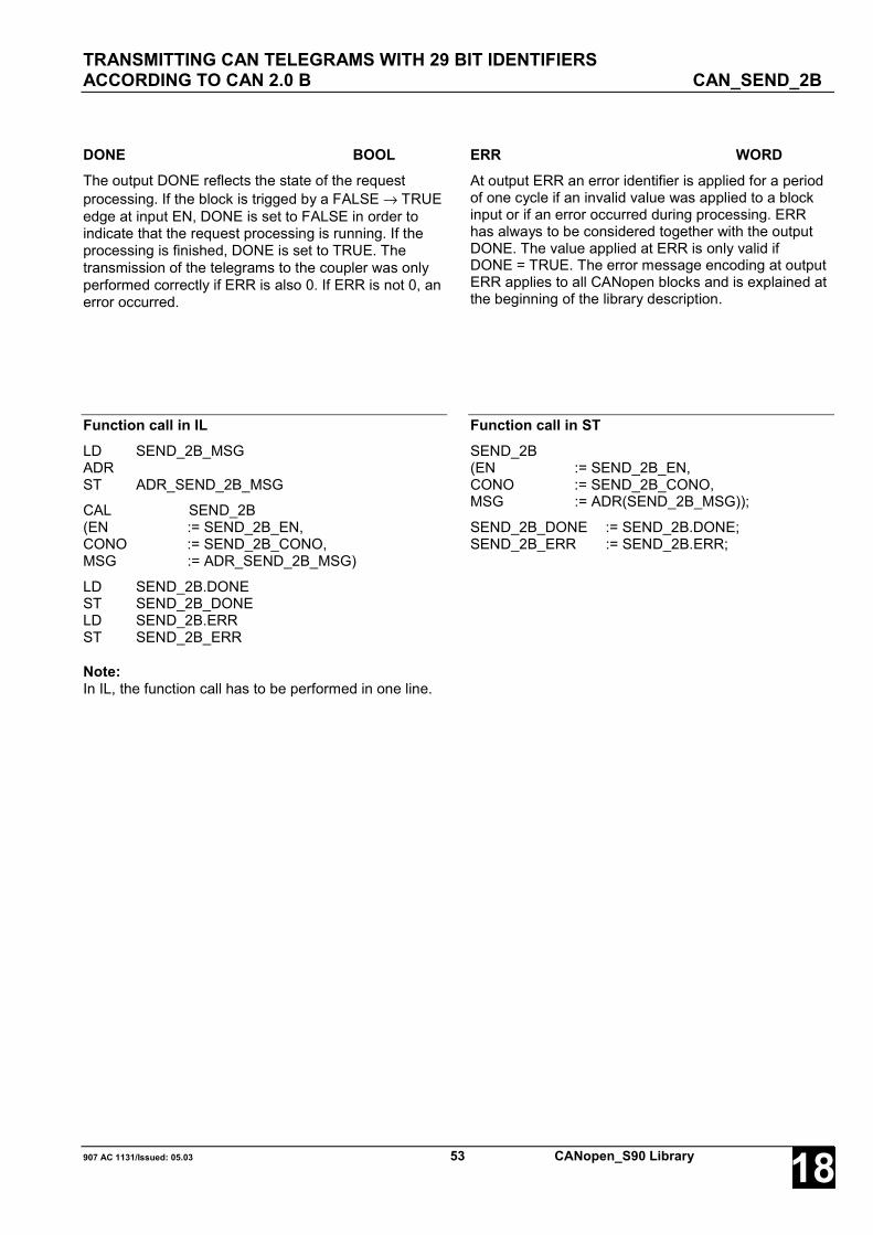
TRANSMITTING CAN TELEGRAMS WITH 29 BIT IDENTIFIERSACCORDING TO CAN 2.0 B CAN_SEND_2B
907 AC 1131/Issued: 05.03 53 CANopen_S90 Library 18
DONE BOOLThe output DONE reflects the state of the requestprocessing. If the block is trigged by a FALSE → TRUEedge at input EN, DONE is set to FALSE in order toindicate that the request processing is running. If theprocessing is finished, DONE is set to TRUE. Thetransmission of the telegrams to the coupler was onlyperformed correctly if ERR is also 0. If ERR is not 0, anerror occurred.
ERR WORDAt output ERR an error identifier is applied for a periodof one cycle if an invalid value was applied to a blockinput or if an error occurred during processing. ERRhas always to be considered together with the outputDONE. The value applied at ERR is only valid ifDONE = TRUE. The error message encoding at outputERR applies to all CANopen blocks and is explained atthe beginning of the library description.
Function call in ILLD SEND_2B_MSGADRST ADR_SEND_2B_MSG
CAL SEND_2B(EN := SEND_2B_EN,CONO := SEND_2B_CONO,MSG := ADR_SEND_2B_MSG)
LD SEND_2B.DONEST SEND_2B_DONELD SEND_2B.ERRST SEND_2B_ERR
Note:In IL, the function call has to be performed in one line.
Function call in STSEND_2B(EN := SEND_2B_EN,CONO := SEND_2B_CONO,MSG := ADR(SEND_2B_MSG));
SEND_2B_DONE := SEND_2B.DONE;SEND_2B_ERR := SEND_2B.ERR;

CANopen_S90 Library 54 907 AC 1131/Issued: 05.0318
Glossary
BOOLVariables of the type BOOL can have the values TRUE and FALSE. For this, 8 bit memory space are reserved.
DINTDINT belongs to the integer data types.
The different numerical types are responsible for a different numerical range. For integer data types the followingrange limits are valid:
Type Lower limit Upper limit Memory spaceDINT: -2147483648 2147483647 32 bits
Due to this, it is possible that information are lost when converting greater data types to smaller data types.
DWORDDWORD belongs to the integer data types.
The different numerical types are responsible for a different numerical range. For integer data types the followingrange limits are valid:
Type Lower limit Upper limit Memory spaceDWORD 0 4294967295 32 bits
Due to this, it is possible that information are lost when converting greater data types to smaller data types.
INTINT belongs to the integer data types.
The different numerical types are responsible for a different numerical range. For integer data types the followingrange limits are valid:
Type Lower limit Upper limit Memory spaceINT: -32768 32767 16 bits
Due to this, it is possible that information are lost when converting greater data types to smaller data types.
WORDWORD belongs to the integer data types.
The different numerical types are responsible for a different numerical range. For integer data types the followingrange limits are valid:
Type Lower limit Upper limit Memory spaceWORD 0 65535 16 bits
Due to this, it is possible that information are lost when converting greater data types to smaller data types.
THE CANOPEN LIBRARY
907 AC 1131/Issued: 05.03 55 CANopen_S90 Library 18
FunctionsFunctions are subroutines which have multiple input parameters and return exactly one result element. Thereturned result can be of an elementary or a derived data type. Due to this, a function may also return an array, astructure, an array of structures and so on.
For the same input parameters, functions always return the same result (they do not have an internal memory).
Therefore, the following rules can be derived:
• Within functions, global variables can neither be read nor written.• Within functions, absolute operands can neither be read nor written.• Within functions, function blocks must not be called.
Function blocksFunction blocks are subroutines which can have as many inputs, outputs and internal variables as required. Theyare called from a program or from another function block.
As they can be used several times (with different data records), function blocks (code and interface) can beconsidered as type. When assigning an individual data record (declaration) to the function block, a function blockinstance is generated.
In contrast to functions, function blocks can contain statically local data which are saved from one call to the next.Therefore e.g. counters can be realized which may not forget their counter value. I.e. function blocks can have aninternal memory.
Functions and function blocks differ in two essential points:
• A function block has multiple output parameters, a function only one. The output parameters of functions andfunction blocks differ syntactically.• In contrast to a function, a function block can have an internal memory.
1. Function blocks with historical values (memory):
For function blocks with historical values it has to be observed that instance names may not be defined severaltimes if different data sets should be called.
2. Function blocks without historical values (memory):
For function blocks without historical values only one instance has to be defined for the FB type. This instance canbe used for several calls of the FB (also with different I/O values).
The instance name can be defined without any restrictions. The type is preset and identical to the function blockname.
THE CANOPEN LIBRARY

CANopen_S90 Library 56 907 AC 1131/Issued: 05.0318
Index
CCAN_REC_2A S90 40
CAN_REC_2B S90 49
CAN_REC_FILTER_2A S90 43
CAN_SEND_2A S90 46
CAN_SEND_2B S90 52
CANoM_NMT S90 34
CANoM_NODEDIAG S90 15
CANoM_RES_ERR S90 19
CANoM_SDO_READ S90 28
CANoM_SDO_WRITE S90 31
CANoM_STAT S90 21
CANoM_SYSDIAG S90 26
CANopen S90
CAN_REC_2A 40
CAN_REC_2B 49
CAN_REC_FILTER_2A 43
CAN_SEND_2A 46
CAN_SEND_2B 52
CANoM_NMT 34
CANoM_NODEDIAG 15
CANoM_RES_ERR 19
CANoM_SDO_READ 28
CANoM_SDO_WRITE 31
CANoM_STAT 21
CANoM_SYSDIAG 26
CANopen_INFO 13
IDENT_CAN2A_TO_WORD 36
IDENT_CANopen_TO_WORD 38
WORD_TO_IDENT_CAN2A 37
WORD_TO_IDENT_CANopen 39
CANopen_INFO S90 13
components of the library 3
IIDENT_CAN2A_TO_WORD S90 36
IDENT_CANopen_TO_WORD S90 38
WWORD_TO_IDENT_CAN2A S90 37
WORD_TO_IDENT_CANopen S90 39
THE CANOPEN LIBRARY

Software Description Advant Controller 31Intelligent DecentralizedAutomation System
EthernetFunction Block Library90 Series
Ethernet90 Series

907 AC 1131/Issued: 04.03 1 Ethernet_S90 Library 18
Contents
The Ethernet library 2SPECIAL CHARACTERISTICS OF THE ETHERNET LIBRARY ................................. 2COMPONENTS OF THE ETHERNET LIBRARY ................................. 2ERROR MESSAGES OF THE ETHERNET LIBRARY BLOCKS ................................. 3
Overview of blocks arranged according to their call names 6READING INFORMATION ABOUT THE INSTALLED COUPLERS ETH_INFO................ 7INITIALIZING THE ETHERNET UDP/IP DATA EXCHANGE ETH_AINIT ............... 9READING AN ETHERNET UDP/IP DATA PACKAGEFROM THE RECEIVE BUFFER ETH_AREC ............ 14TRANSMITTING AN ETHERNET UDP/IP DATA PACKAGE ETH_ASEND.......... 17READING ETHERNET UDP/IP TIMEOUT DATA PACKAGES ETH_ASTO ............ 20READING STATUS INFORMATION ABOUTOPENMODBUS PROCESSING ETH_MODSTAT .... 23PROCESSING OPENMODBUS ON TCP/IP CLIENT TELEGRAMS ETH_MODMAST.... 26
Glossary 29
Index 31

THE ETHERNET LIBRARY
Ethernet_S90 Library 2 907 AC 1131/Issued: 04.0318
The Ethernet librarySPECIAL CHARACTERISTICS OF THE ETHERNET LIBRARYNote:
Ethernet communication is only performed in RUN mode of the PLC, but not in simulation mode.
Operating the controller as OpenModbus on TCP/IP subscriber can be performed simultaneously with otherprotocols. When operated in this mode, the Ethernet coupler is able to execute the functionality of several serversor several clients at the same time. Mixed operation is also possible. Configuring the coupler accordingly has to bedone by means of 907 FB 1131 (refer to 907 FB 1131 documentation).
In order to operate the controller as OpenModbus on TCP/IP server (slave), only the coupler has to be configuredaccordingly using 907 FB 1131. An additional use of the OpenModbus on TCP/IP blocks in the user program is notnecessary.
To operate the controller as OpenModbus on TCP/IP client (master), the coupler also has to be configured using907 FB 1131. In this case, one or more ETH_MODMAST blocks have to be planned in the user programadditionally.
The ETH_MODMAST block can be optionally operated in server mode as well as in client mode or in mixedoperation.
The following ports are reserved:
Portdez hex Reserved for
32768 8000 Ethernet UDP/IP data exchange (ETH_Axxx-blocks)1200 04B0 TCP/IP Gateway access502 01F6 OpenModbus on TCP/IP
COMPONENTS OF THE ETHERNET LIBRARYThe Ethernet library contains the following function blocks:
Group: GeneralETH_INFO - Reading information about installed couplers
Group: UDP_IPETH_AINIT - Initializing the Ethernet UDP/IP data exchange
ETH_ASEND - Transmitting a data package to a subscriber via Ethernet UDP/IP
ETH_AREC - Reading a data package from the Ethernet UDP/IP receive buffer
ETH_ASTO - Reading Ethernet UDP/IP timeout data packages from the timeout data buffer
Group: MODBUS_TCP (OpenModbus on TCP/IP)ETH_MODSTAT - Reading status information of the OpenModbus on TCP/IP processing
ETH_MODMAST - Processing OpenModbus on TCP/IP client (master) telegrams
Detailed information about the various blocks can be found in the following sections.

THE ETHERNET LIBRARY
907 AC 1131/Issued: 04.03 3 Ethernet_S90 Library 18
ERROR MESSAGES OF THE ETHERNET LIBRARY BLOCKSThe following errors are signalized at output ERR of the ETH_xxx blocks:
Errors at block inputs:
DEC HEX Error description8193 2001 Invalid value at block input CONO8194 2002 Coupler model in slot CONO does not correspond to the block type8195 2003 No Ethernet coupler in slot CONO8196 2004 Ethernet coupler in slot CONO is not in OPERATE state8202 200A Invalid data length at block input8203 200B Invalid socket number at block input
Error messages of the ETH library:
DEC HEX Error description8449 2101 Invalid socket ID8450 2102 Coupler cannot be accessed. System is waiting for free resources8451 2103 Invalid socket number8452 2104 Socket is already open and active8453 2105 No free socket available8454 2106 Invalid socket state8455 2107 Invalid command8456 2108 Invalid data length8457 2109 Error while accessing the data buffer8458 210A The coupler performed a reset during processing. Processing was aborted.8480 2120 Data buffer full8481 2121 Error while creating the data buffer8482 2122 Data could not be read from the buffer or written to the buffer successfully //
Accessed buffer is empty or full

THE ETHERNET LIBRARY
Ethernet_S90 Library 4 907 AC 1131/Issued: 04.0318
Errors during execution of UDP/IP-TCP/IP, coupler response
DEC HEX Error description9266 2432 TCP/UDP task not available9267 2433 Internal task with configuration data not available9268 2434 No MAC address available9269 2435 Waiting for warm start performed by the application9270 2436 Unknown flag in start parameters9271 2437 Invalid IP address in start parameters9272 2438 Invalid subnet mask in start parameters9273 2439 Invalid gateway IP in start parameters9275 243B Unknown device type9276 243C Access to IP address in the specified source failed9277 243D Initialization of the driver layer failed9278 243E No source specified for IP address (BOOTP, DHCP, IP address parameter)9326 246E Timeout has occurred9327 246F Invalid timeout parameter9328 2470 Invalid socket9329 2471 Command cannot be executed. Socket not ready9331 2473 No access to target IP address9332 2474 Invalid option parameter9333 2475 Invalid command parameter9334 2476 Invalid IP address or no access to address9335 2477 Invalid port number or port not available9336 2478 Connection closed9337 2479 Connection reset9338 247A Invalid protocol parameter9339 247B No socket available9340 247C Invalid MAC address9346 2482 Invalid mode parameter9347 2483 Maximum data length exceeded9348 2484 Maximum number of messages exceeded9349 2485 Maximum number of IP multicast groups exceeded9350 2486 ARP not found in ARP cache9365 2495 Unexpected response message received9367 2497 Invalid message length9368 2498 Unknown message command9372 249C Sequence error during transmission in sequence message mode9374 249E Command cannot be executed or command is currently executed9416 24C8 Task not initialized9426 24D2 No configuration data available9428 24D4 Error while reading the configuration data9429 24D5 Error while creating the diagnosis structure9434 24DA Not enough memory available

THE ETHERNET LIBRARY
907 AC 1131/Issued: 04.03 5 Ethernet_S90 Library 18
Errors during execution of OpenModbus on TCP/IP, coupler response
DEC HEX Error description9268 2434 Invalid parameter for "ServerConnection"9269 2435 Invalid parameter for "Task Timeout"9270 2436 Invalid parameter for "OBM Timeout"9271 2437 Invalid parameter for "Mode"9272 2438 Invalid parameter for "Send Timeout"9273 2439 Invalid parameter for "Connect Timeout"9274 243A Invalid parameter for "Close Timeout"9275 243B Invalid parameter for "Swab"9276 243C TCP task not ready9277 243D PLC task not ready9278 243E Error during initialization9327 246F Unknown send or receive telegram9328 2470 TCP responds with an error9329 2471 No corresponding socket found9330 2472 Command with invalid value9331 2473 Error in TCP clock status9332 2474 Error in Modbus telegram9333 2475 No free socket found9334 2476 TCP command is directed to an unknown socket9335 2477 Time for a client job is over9336 2478 Socket has been closed unexpectedly9337 2479 Not-Ready flag has been set by the user9338 247A OMB task cannot open socket9339 247B Watchdog event in the PLC task; only in IO mode9340 247C TCP task not in configuration state9341 247D PLC task not initialized9342 247E Server socket was closed without response from the device9367 2497 Invalid message length9368 2498 Unknown message command9376 24A0 Error in telegram header9377 24A1 Invalid address detected in the telegram9379 24A3 Invalid data address9381 24A5 Invalid data counter9383 24A7 OBM task received an error in the response of the TCP task9418 24CA OBM task does not have a segment from RCS9419 24CB Unknown or invalid sender contained in the command

OVERVIEW OF BLOCKS ARRANGED ACCORDING TO THEIR CALL NAMES
Ethernet_S90 Library 6 907 AC 1131/Issued: 04.0318
Overview of blocks arranged according to their call names
Character description:
FBhv … Function block with historical values
FBnohv… Function block without historical values
F … Function
CE name Type Function Page
ETH_AINIT FBhv Initializing the Ethernet UDP/IP data exchange 9
ETH_AREC FBhv Reading a data package from the Ethernet UDP/IP receive buffer 14
ETH_ASEND FBhv Transmitting a data package to a subscriber via Ethernet UDP/IP 17
ETH_ASTO FBhv Reading Ethernet UDP/IP timeout data packages from the timeout databuffer
20
ETH_INFO FBnohv Reading information about the installed couplers 7
ETH_MODSTAT FBhv Reading status information of the OpenModbus on TCP/IP processing 23
ETH_MODMAST FBhv Processing OpenModbus on TCP/IP client (master) telegrams 26

READING INFORMATION ABOUT THE INSTALLED COUPLERS ETH_INFO
907 AC 1131/Issued: 04.03 7 Ethernet_S90 Library 18
READING INFORMATION ABOUT THE INSTALLED COUPLERS ETH_INFOThe block ETH_INFO outputscoupler related information.The following items aredisplayed: Coupler type andmodel, operation mode,manufacturing date, devicenumber and serial number aswell as firmware designationand firmware version.
Block dataAvailable as of PLC runtime system: V5.0 Remark:Included in library: Ethernet_S90_V50.LIB
Block typeFunction block without historical values
ParametersInstance ETH_INFO Instance nameCONO BYTE Slot (module number) of the couplerERR WORD Error messageTYP STRING(17) Coupler typeMODEL STRING(22) Coupler modelOP_MODE STRING(22) Operation mode of the couplerMAN_DATE DATE Manufacturing date of the couplerDEV_NO DWORD Device number of the couplerSER_NO DWORD Serial number of the couplerFW_NAME STRING(17) Designation of the coupler firmwareFW_VER STRING(17) Version of the coupler firmware
Description
The ETH_INFO block is always active. It reads the slotnumber at the block input CONO and outputs thecorresponding information about the selected coupler.
ETH_INFO recognizes different coupler types. For thatreason, the block outputs do not only relate to theEthernet coupler.
The block is not intended for use in normal userprograms. It should be used to support fault diagnosisand maintenance operations.
CONO BYTE
At input CONO the slot (module number) of the coupleris applied for which the information should be polled.The module number depends on the PLC category.
The following applies:07 KT 9x R027x CONO = 0, 107 KT 9x R02x7 CONO = 2
ERR WORDAn error identification is provided at output ERR, if aninvalid value is applied at input CONO. The errormessage encoding at output ERR applies to allEthernet blocks and is explained at the beginning of thelibrary descriptions.
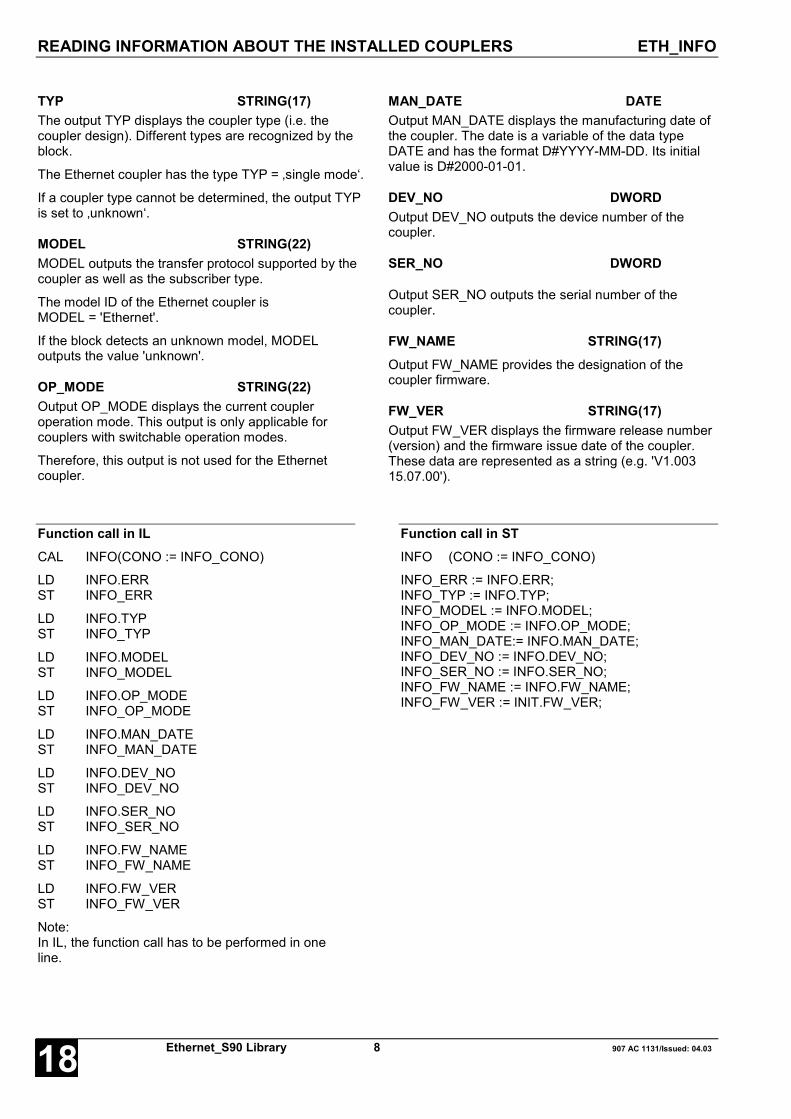
READING INFORMATION ABOUT THE INSTALLED COUPLERS ETH_INFO
Ethernet_S90 Library 8 907 AC 1131/Issued: 04.0318
TYP STRING(17)The output TYP displays the coupler type (i.e. thecoupler design). Different types are recognized by theblock.
The Ethernet coupler has the type TYP = ‚single mode‘.
If a coupler type cannot be determined, the output TYPis set to ‚unknown‘.
MODEL STRING(22)MODEL outputs the transfer protocol supported by thecoupler as well as the subscriber type.
The model ID of the Ethernet coupler isMODEL = 'Ethernet'.
If the block detects an unknown model, MODELoutputs the value 'unknown'.
OP_MODE STRING(22)Output OP_MODE displays the current coupleroperation mode. This output is only applicable forcouplers with switchable operation modes.
Therefore, this output is not used for the Ethernetcoupler.
MAN_DATE DATEOutput MAN_DATE displays the manufacturing date ofthe coupler. The date is a variable of the data typeDATE and has the format D#YYYY-MM-DD. Its initialvalue is D#2000-01-01.
DEV_NO DWORDOutput DEV_NO outputs the device number of thecoupler.
SER_NO DWORD
Output SER_NO outputs the serial number of thecoupler.
FW_NAME STRING(17)Output FW_NAME provides the designation of thecoupler firmware.
FW_VER STRING(17)Output FW_VER displays the firmware release number(version) and the firmware issue date of the coupler.These data are represented as a string (e.g. 'V1.00315.07.00').
Function call in ILCAL INFO(CONO := INFO_CONO)
LD INFO.ERRST INFO_ERR
LD INFO.TYPST INFO_TYP
LD INFO.MODELST INFO_MODEL
LD INFO.OP_MODEST INFO_OP_MODE
LD INFO.MAN_DATEST INFO_MAN_DATE
LD INFO.DEV_NOST INFO_DEV_NO
LD INFO.SER_NOST INFO_SER_NO
LD INFO.FW_NAMEST INFO_FW_NAME
LD INFO.FW_VERST INFO_FW_VER
Note:In IL, the function call has to be performed in oneline.
Function call in STINFO (CONO := INFO_CONO)
INFO_ERR := INFO.ERR;INFO_TYP := INFO.TYP;INFO_MODEL := INFO.MODEL;INFO_OP_MODE := INFO.OP_MODE;INFO_MAN_DATE:= INFO.MAN_DATE;INFO_DEV_NO := INFO.DEV_NO;INFO_SER_NO := INFO.SER_NO;INFO_FW_NAME := INFO.FW_NAME;INFO_FW_VER := INIT.FW_VER;

INITIALIZING THE ETHERNET UDP/IP DATA EXCHANGE ETH_AINIT
907 AC 1131/Issued: 04.03 9 Ethernet_S90 Library 18
INITIALIZING THE ETHERNET UDP/IP DATA EXCHANGE ETH_AINITETH_AINIT initializes theEthernet UDP/IP dataexchange for the blocksETH_ASEND, ETH_AREC andETH_ASTO.
Block dataAvailable as of PLC runtime system: V5.0 Remark:Included in library: Ethernet_S90_V50.LIB
Block typeFunction block with historical values
ParametersInstance ETH_AINIT Instance nameEN BOOL Initialization of the Ethernet UDP/IP data exchange with a FALSE/TRUE
edge. A TRUE/FALSE edge stops the processing.LRH WORD Receive buffer length in bytesLSHB WORD Transmit buffer length for high priority in bytesLSLB WORD Transmit buffer length for low priority in bytesLSTOB WORD Buffer length for timeout data packages in bytesLHEAD WORD Number of header data to be copied for timeout packages in bytesENBC BOOL Enable/disable broadcast reception (data packages to all stations)
(currently not working)ENRA BOOL Overwrite/disable receive buffer on buffer overflowDONE BOOL Initialization completed or error occurredERR WORD Error numberSTAT WORD UDP/IP processing stateIP_ADR DWORD IP address of the Ethernet card in slot CONOSOCK BYTE Used socket numberCREBC WORD Counter for received broadcasts (data packages to all stations)
(currently not working)LEVHP_BY WORD Filling level of the transmit buffer for high priority in bytesLEVHP_DS WORD Filling level of the transmit buffer for high priority in data recordsLEVLP_BY WORD Filling level of the transmit buffer for low priority in bytesLEVLP_DS WORD Filling level of the transmit buffer for low priority in data recordsLEVR_BY WORD Filling level of the receive buffer in bytesLEVR_DS WORD Filling level of the receive buffer in data recordsLEVLTOS WORD Filling level of the timeout data packages buffer in data records
After a successful initialization, all outputs are updated with each block call if a TRUE signal is applied to input EN.

INITIALIZING THE ETHERNET UDP/IP DATA EXCHANGE ETH_AINIT
Ethernet_S90 Library 10 907 AC 1131/Issued: 04.0318
Description
The block ETH_AINIT initializes the Ethernet UDP/IPprocessing with variable buffer lengths. There is onetransmit buffer for high priority and one for low priorityas well as one receive buffer and a buffer for datapackages which could not be transmitted successfully(timeout data packages). All buffers can be set variably(LRH, LSHB, LSLB, LSTOB).
If acknowledgement is active (refer to input TOUT ofthe block ETH_ASEND), the number of timeout datapackage header data to be copied can be specified viainput LHEAD.
The reception of broadcast telegrams is enabled byapplying a TRUE signal to input ENBC.
Output DONE indicates that the initialization wascompleted successfully or that an error occurred. If anerror was detected during the processing of the block,the error is additionally indicated at output ERR.Furthermore, the block provides information about thefilling levels of the transmit, receive and timeout buffersin bytes (LEVHP_BY, LEVLP_BY, LEVR_BY) and datarecords (LEVHP_DS, LEVLP_DS, LEVR_DS,LEVLTOS) and outputs the used IP address (IP_ADR)and socket number(SOCK).
The blocks ETH_ASEND, ETH_AREC and ETH_ASTOcan only be used after successful initialization. Theblock ETH_AINIT may only be planned once for eachEthernet coupler.
EN BOOLA FALSE/TRUE edge at input EN initiates theinitialization of the Ethernet UDP/IP data exchange. Ifno error is detected, data exchange via EthernetUDP/IP is enabled. Input EN has to be TRUE as longas the data exchange is going on.
The following applies:EN = FALSE: Initialization inactive. No dataexchange possible.EN = TRUE: Initialization is initiated. Data exchangeis enabled.
CONO BYTE
At input CONO the coupler slot (module number) isselected which should be used by this block. Themodule number depends on the PLC category.
The following applies:07 KT 9x R027x CONO = 0, 107 KT 9x R02x7 CONO = 2
LRH WORDAt input LRH the desired receive buffer length isspecified in bytes.
LSHB WORDAt input LSHB the desired high priority transmit bufferlength is specified in bytes.
LSLB WORDAt input LSLB the desired low priority transmit bufferlength is specified in bytes.
LSTOB WORDAt input LSTOB the desired buffer length for timeoutdata packages is specified in bytes.
LHEAD WORDInput LHEAD determines the number of timeout datapackage header data to be copied into the readabletimeout buffer (refer to block ETH_ASTO).
ENBC BOOLInput ENBC is used to enable or disable the receptionof broadcasts (data packages to all stations).
The following applies:ENBC = FALSE Broadcast reception disabledENBC = TRUE Broadcast reception enabled
(currently not working)
ENRA BOOL
Input ENRA is used to determine how new incomingdata packages are to be handled if the receive buffer isfull.
The following applies:ENRA = FALSEThe oldest data packages stored in the receive bufferare overwritten with the new incoming data packages.ENRA = TRUEThe new incoming data are dismissed.
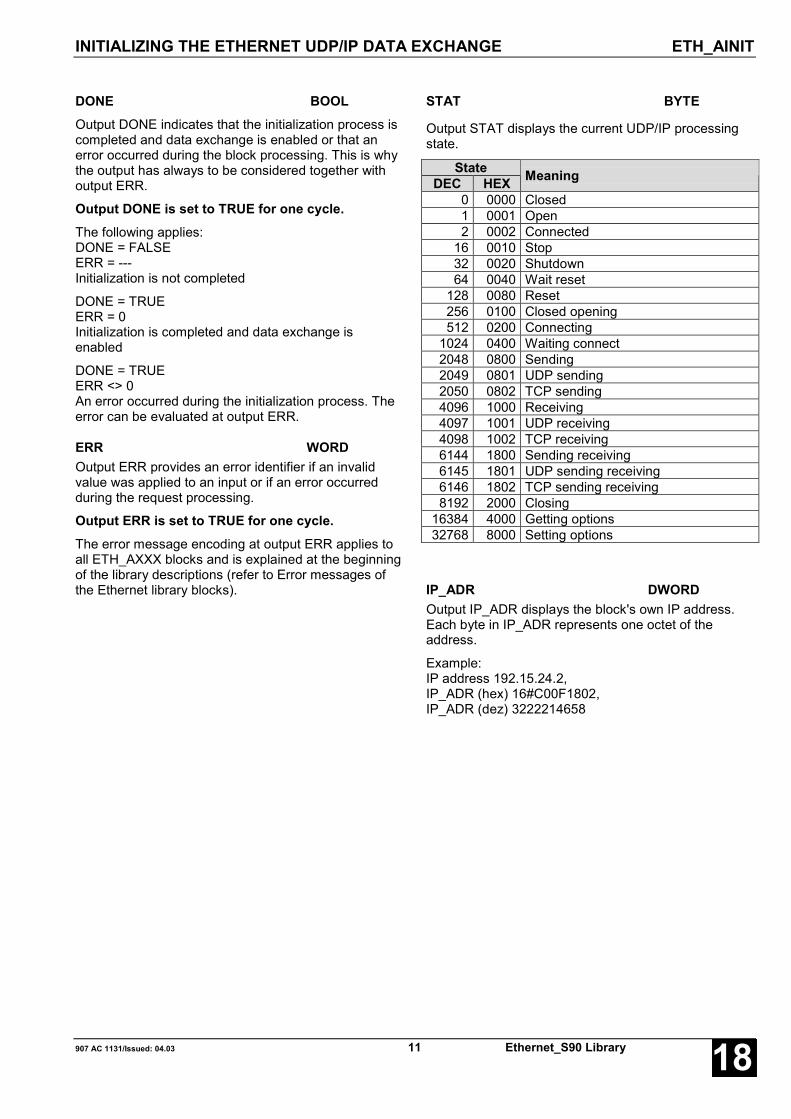
INITIALIZING THE ETHERNET UDP/IP DATA EXCHANGE ETH_AINIT
907 AC 1131/Issued: 04.03 11 Ethernet_S90 Library 18
DONE BOOLOutput DONE indicates that the initialization process iscompleted and data exchange is enabled or that anerror occurred during the block processing. This is whythe output has always to be considered together withoutput ERR.
Output DONE is set to TRUE for one cycle.The following applies:DONE = FALSEERR = ---Initialization is not completed
DONE = TRUEERR = 0Initialization is completed and data exchange isenabled
DONE = TRUEERR <> 0An error occurred during the initialization process. Theerror can be evaluated at output ERR.
ERR WORDOutput ERR provides an error identifier if an invalidvalue was applied to an input or if an error occurredduring the request processing.
Output ERR is set to TRUE for one cycle.The error message encoding at output ERR applies toall ETH_AXXX blocks and is explained at the beginningof the library descriptions (refer to Error messages ofthe Ethernet library blocks).
STAT BYTE
Output STAT displays the current UDP/IP processingstate.
StateDEC HEX Meaning
0 0000 Closed1 0001 Open2 0002 Connected
16 0010 Stop32 0020 Shutdown64 0040 Wait reset
128 0080 Reset256 0100 Closed opening512 0200 Connecting
1024 0400 Waiting connect2048 0800 Sending2049 0801 UDP sending2050 0802 TCP sending4096 1000 Receiving4097 1001 UDP receiving4098 1002 TCP receiving6144 1800 Sending receiving6145 1801 UDP sending receiving6146 1802 TCP sending receiving8192 2000 Closing
16384 4000 Getting options32768 8000 Setting options
IP_ADR DWORDOutput IP_ADR displays the block's own IP address.Each byte in IP_ADR represents one octet of theaddress.
Example:IP address 192.15.24.2,IP_ADR (hex) 16#C00F1802,IP_ADR (dez) 3222214658

INITIALIZING THE ETHERNET UDP/IP DATA EXCHANGE ETH_AINIT
Ethernet_S90 Library 12 907 AC 1131/Issued: 04.0318
SOCK BYTEOutput SOCK displays the socket number used forEthernet UDP/IP processing.
CREBC WORDOutput CREBC displays the number of broadcasts(data packages to all stations) received by this stationsince the occurrence of the FALSE/TRUE edge at inputEN.
(currently not working)
LEVHP_BY WORDAs long as EN = TRUE, output LEVHP_BY displays thefilling level of the high priority transmit buffer in bytes.
LEVHP_DS WORDAs long as EN = TRUE, output LEVHP_DS displays thefilling level of the high priority transmit buffer in datarecords.
LEVLP_BY WORDAs long as EN = TRUE, output LEVLP_BY displays thefilling level of the low priority transmit buffer in bytes.
LEVLP_DS WORDAs long as EN = TRUE, output LEVLP_DS displays thefilling level of the low priority transmit buffer in datarecords.
LEVR_BY WORDAs long as EN = TRUE, output LEVR_BY displays thefilling level of the receive buffer in bytes.
LEVR_DS WORDAs long as EN = TRUE, output LEVR_DS displays thefilling level of the receive buffer in data records.
LEVLTOS WORDAs long as EN = TRUE, output LEVLTOS displays thefilling level of the timeout buffer in data records.
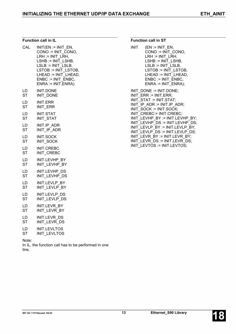
INITIALIZING THE ETHERNET UDP/IP DATA EXCHANGE ETH_AINIT
907 AC 1131/Issued: 04.03 13 Ethernet_S90 Library 18
Function call in ILCAL INIT(EN := INIT_EN,
CONO := INIT_CONO,LRH := INIT_LRH,LSHB := INIT_LSHB,LSLB := INIT_LSLB,LSTOB := INIT_LSTOB,LHEAD := INIT_LHEAD,ENBC := INIT_ENBC,ENRA := INIT.ENRA)
LD INIT.DONEST INIT_DONE
LD INIT.ERRST INIT_ERR
LD INIT.STATST INIT_STAT
LD INIT.IP_ADRST INIT_IP_ADR
LD INIT.SOCKST INIT_SOCK
LD INIT.CREBCST INIT_CREBC
LD INIT.LEVHP_BYST INIT_LEVHP_BY
LD INIT.LEVHP_DSST INIT_LEVHP_DS
LD INIT.LEVLP_BYST INIT_LEVLP_BY
LD INIT.LEVLP_DSST INIT_LEVLP_DS
LD INIT.LEVR_BYST INIT_LEVR_BY
LD INIT.LEVR_DSST INIT_LEVR_DS
LD INIT.LEVLTOSST INIT_LEVLTOS
Note:In IL, the function call has to be performed in oneline.
Function call in STINIT (EN := INIT_EN,
CONO := INIT_CONO,LRH := INIT_LRH,LSHB := INIT_LSHB,LSLB := INIT_LSLB,LSTOB := INIT_LSTOB,LHEAD := INIT_LHEAD,ENBC := INIT_ENBC,ENRA := INIT_ENRA);
INIT_DONE := INIT.DONE;INIT_ERR := INIT.ERR;INIT_STAT := INIT.STAT;INIT_IP_ADR := INIT.IP_ADR;INIT_SOCK := INIT.SOCK;INIT_CREBC:= INIT.CREBC;INIT_LEVHP_BY := INIT.LEVHP_BY;INIT_LEVHP_DS := INIT.LEVHP_DS;INIT_LEVLP_BY := INIT.LEVLP_BY;INIT_LEVLP_DS := INIT.LEVLP_DS;INIT_LEVR_BY := INIT.LEVR_BY;INIT_LEVR_DS := INIT.LEVR_DS;INIT_LEVTOS := INIT.LEVTOS;

READING AN ETHERNET UDP/IP DATA PACKAGEFROM THE RECEIVE BUFFER ETH_AREC
Ethernet_S90 Library 14 907 AC 1131/Issued: 04.0318
READING AN ETHERNET UDP/IP DATA PACKAGEFROM THE RECEIVE BUFFER ETH_ARECThe ETH_ARECblock reads the nextdata record from theUDP/IP receivebuffer and suppliesthe user data in theplanned memoryarea.
Block dataAvailable as of PLC runtime system: V5.0 Remark:Included in library: Ethernet_S90_V50.LIB
Block typeFunction block with historical values
ParametersInstance ETH_AREC Instance nameEN BOOL Enabling of the block processingCONO BYTE Slot (module number) of the couplerDATA DWORD Variable in which the received user data shall be
stored. The variable has to be of the type ARRAY orSTRUCT.
DONE BOOL Data package available or error occurredERR WORD Error numberIP_ADR WORD IP address of the sending deviceLEN WORD Data package length in bytesLEVR_BY WORD Receive buffer filling level in bytesLEVR_DS WORD Receive buffer filling level in data records
DescriptionThe operating system reads the received UDP/IP datapackages from the ETHERNET coupler and storesthem in the receive buffer. The buffer size isdetermined using the ETH_AINIT block. The datapackages are stored with variable lengths. Forexample, a data package consisting of 16 bytes of userdata occupies exactly 22 bytes in the receive buffer (4bytes for the IP address of the sending device, 2 bytesfor the packet length and 16 bytes of user data).
Using the ETH_AREC block exactly one data packageis read. The user data are stored in the plannedmemory area (DATA). The address of the sendingdevice and the data package length are supplied at theoutputs IP_ADR and LEN. DONE = TRUE andERR = 0 indicate that the reading process wassuccessful. If an error was detected during the blockprocessing, the error is indicated at output ERR.Furthermore, the block provides information about the
receive buffer filling level displayed in bytes (LEVR_BY)and data records (LEVR_DS).
The ETH_AREC block cannot read data packages fromthe receive buffer until the ETHERNET UDP/IPprocessing has been initialized by the ETH_AINITblock.

READING AN ETHERNET UDP/IP DATA PACKAGEFROM THE RECEIVE BUFFER ETH_AREC
907 AC 1131/Issued: 04.03 15 Ethernet_S90 Library 18
EN BOOLReading of the receive buffer is performed dependingon the signal applied at input EN.
The following applies:EN = FALSE: Do not read receive bufferEN = TRUE: Read receive buffer
CONO BYTE
At input CONO the coupler slot (module number) isselected which should be used by this block. Themodule number depends on the PLC category.
The following applies:07 KT 9x R027x CONO = 0, 107 KT 9x R02x7 CONO = 2
DATA DWORDInput DATA is used to specify the variable address towhich the user data shall be copied. The addressspecified at DATA has to belong to a variable of thetype ARRAY or STRUCT.
CAUTION: Adjust the variable size to the maximumexpected amount of data in order to avoidoverlapping of memory areas.
DONE BOOLOutput DONE indicates that the user data of a datapackage were continuously copied from the receivebuffer into the memory area of the variable specified atDATA or that the block processing was aborted due toan occurring error. This is why the output has always tobe considered together with output ERR.
Output DONE is set to TRUE for one cycle.The following applies:
DONE = FALSEERR = ---:The data package was not read from the receive buffer.
DONE = TRUEERR = 0:The data package was successfully read from thereceive buffer.
DONE = TRUEERR <> 0:An error occurred while reading the user data from the
receive buffer. The user data were not copied to thearea specified at DATA. The error can be evaluated atoutput ERR.
ERR WORDOutput ERR provides an error identifier for a period ofone cycle if an invalid value was applied to an input or ifan error occurred during processing the job. ERR hasalways to be considered together with output DONE.The value provided at ERR is only valid ifDONE = TRUE. The error message encoding at outputERR applies to all ETH_Axxx blocks and is explainedat the beginning of the library descriptions (refer toError messages of the Ethernet library blocks).
IP_ADR DWORDOutput IP_ADR displays the IP address of the sendingdevice which transmitted the received data package.Each byte in IP_ADR represents one octet of theaddress.
Example:IP address 192.15.24.2,IP_ADR (hex) 16#C00F1802,IP_ADR (dez) 3222214658
LEN WORDOutput LEN displays the length of the received datapackage in bytes.
LEVR_BY WORDOutput LEVR_BY displays the filling level of the receivebuffer in bytes. The displayed value is updated as longas EN is TRUE and applies to the input values readwith the rising edge at input EN.
One data package occupies output LEN + 6 bytes inthe receive buffer (4 bytes for the IP address of thesending device, 2 bytes for the specification of thelength).
LEVR_DS WORDOutput LEVR_DS displays the filling level of the receivebuffer in data records. The displayed value is updatedas long as EN is TRUE and applies to the input valuesread with the rising edge at input EN.
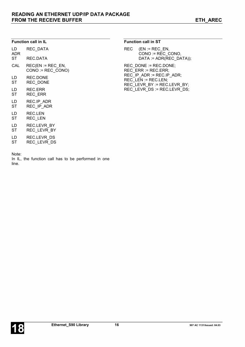
READING AN ETHERNET UDP/IP DATA PACKAGEFROM THE RECEIVE BUFFER ETH_AREC
Ethernet_S90 Library 16 907 AC 1131/Issued: 04.0318
Function call in ILLD REC_DATAADRST REC.DATA
CAL REC(EN := REC_EN,CONO := REC_CONO)
LD REC.DONEST REC_DONE
LD REC.ERRST REC_ERR
LD REC.IP_ADRST REC_IP_ADR
LD REC.LENST REC_LEN
LD REC.LEVR_BYST REC_LEVR_BY
LD REC.LEVR_DSST REC_LEVR_DS
Note:In IL, the function call has to be performed in oneline.
Function call in STREC (EN := REC_EN,
CONO := REC_CONO,DATA := ADR(REC_DATA));
REC_DONE := REC.DONE;REC_ERR := REC.ERR;REC_IP_ADR := REC.IP_ADR;REC_LEN := REC.LEN;REC_LEVR_BY := REC.LEVR_BY;REC_LEVR_DS := REC.LEVR_DS;

TRANSMITTING AN ETHERNET UDP/IP DATA PACKAGE ETH_ASEND
907 AC 1131/Issued: 04.03 17 Ethernet_S90 Library 18
TRANSMITTING AN ETHERNET UDP/IP DATA PACKAGE ETH_ASENDThe blockETH_ASEND isused to transmitdata packagesvia the UDP/IPprotocol of theETHERNETcoupler.
Block dataAvailable as of PLC runtime system: V5.0 Remark:Included in library: Ethernet_S90_V50.LIB
Block typeFunction block with historical values
ParametersInstance ETH_ASEND Instance nameEN BOOL Enabling of data package transmission
FALSE: do not transmit data packageTRUE: transmit data package
CONO BYTE Slot (module number) of the couplerIP_ADR DWORD Target IP address to which the data shall be transmittedPRIO BOOL Transmission priority of the data package
FALSE = low, TRUE = highTOUT WORD Timeout period of the data package in msDATA DWORD Address of the variable from which on the data shall be copied into the transmit
buffer. The variable has to be of the type ARRAY or STRUCT.LEN WORD Number of user data to be transmitted (in bytes)DONE BOOL Data package stored in transmit buffer or error occurredERR WORD Error numberLEV_BY WORD Filling level (in bytes) of the transmit buffer for low/high priority (depending on input
PRIO)LEV_DS WORD Filling level (in data records) of the transmit buffer for low/high priority (depending on
input PRIO)
DescriptionThe block ETH_ASEND is used to transmit datapackages via the UDP/IP protocol of the ETHERNETcoupler. The planned packages are stored in thetransmit buffer selected via input PRIO. From there, theoperating system hands over the data packages to theETHERNET coupler in order to transmit them to thetarget address specified at input IP_ADR. The transmitbuffer size is determined using the ETH_AINIT block.Using input TOUT the timeout period can be specified.If TOUT <> 0, the UDP/IP data exchange isautomatically performed with receiveacknowledgement. If TOUT = 0, no acknowledgementis expected. Output DONE indicates that the planneddata package has been stored in the transmit buffer or
that an error occurred during block processing. If anerror was detected during block processing, the error isadditionally indicated at output ERR. In case of an errorthe data package has to be transmitted again.
The ETH_ASEND block cannot store data packages tothe transmit buffer until the ETHERNET UDP/IPprocessing has been initialized by the ETH_AINITblock.

TRANSMITTING AN ETHERNET UDP/IP DATA PACKAGE ETH_ASEND
Ethernet_S90 Library 18 907 AC 1131/Issued: 04.0318
EN BOOLDepending on input EN, the planned packet is firststored in the transmit buffer and then transmitted.
The following applies:
EN = FALSE: The planned packet is not stored in thetransmit buffer and therefore nottransmitted.
EN = TRUE: The planned packet is stored in thetransmit buffer and transmitted.
CONO BYTE
At input CONO the coupler slot (module number) isselected which should be used by this block. Themodule number depends on the PLC category.
The following applies:07 KT 9x R027x CONO = 0, 107 KT 9x R02x7 CONO = 2
IP_ADR DWORDAt this input the IP address of the recipient is specified.Each byte in IP_ADR represents one octet of theaddress.
Example:IP address 192.15.24.2,IP_ADR (hex) 16#C00F1802,IP_ADR (dez) 3222214658
PRIO BOOL
Input PRIO is used to specify the transmit priority of thedata package.
The following applies:
PRIO = FALSE: The planned data package has lowpriority. Thus it is stored in the lowpriority transmit buffer. All outputsrefer to this buffer.
PRIO = TRUE: The planned data package has highpriority. Thus it is stored in the highpriority transmit buffer. All outputsrefer to this buffer.
TOUT WORDUsing input TOUT the timeout period can be specified.If TOUT <> 0, the UDP/IP data exchange isautomatically performed with receiveacknowledgement. If a data package cannot betransmitted within this period (no acknowledgetelegram is received), transmission is aborted and thepackage is lost.In this case, some distinctive bytes of the data package(refer to input LHEAD of the ETH_AINIT block) arestored in the timeout buffer and can then be read usingthe ETH_ASTO block.
If TOUT = 0, no acknowledgement is expected.
The following applies:
TOUT = 0: Data exchange without receiveacknowledgement. No data are writtento the timeout buffer.
TOUT <> 0: Data exchange with receiveacknowledgement. Each transmitteddata record is acknowledged by therecipient. If no acknowledge telegram isreceived within the set timeout period(in ms), the data are written to thetimeout buffer.
DATA DWORDAt input DATA the address of the variable is specifiedthe data of which are transmitted as user data in thispackage. The address specified at DATA has to belongto a variable of the type ARRAY or STRUCT.
LEN WORDAt input LEN the number of user data bytes is specifiedfor the planned packet.
The following applies: 1 ≤ LEN ≤ 1464
DONE BOOLOutput DONE indicates that the planned package hasbeen stored in the transmit buffer or that an erroroccurred during block processing. This is why theoutput has always to be considered together withoutput ERR.
Output DONE is set to TRUE for one cycle.The following applies:
DONE = FALSEERR = ---:The planned packet has not been stored in the transmitbuffer.
DONE = TRUEERR = 0:The planned packet has been stored in the transmitbuffer.
DONE = TRUEERR <> 0:An error occurred during transmission. The planneddata packet was stored in the transmit buffer. The errorcan be evaluated at output ERR.
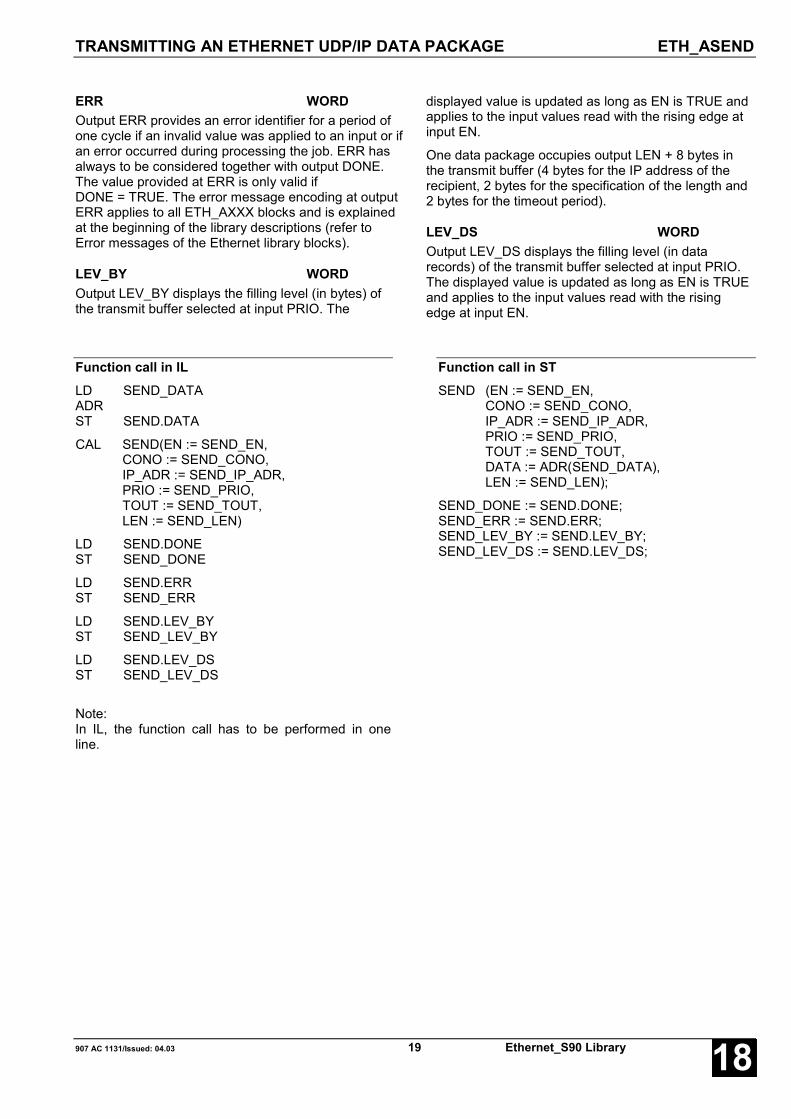
TRANSMITTING AN ETHERNET UDP/IP DATA PACKAGE ETH_ASEND
907 AC 1131/Issued: 04.03 19 Ethernet_S90 Library 18
ERR WORDOutput ERR provides an error identifier for a period ofone cycle if an invalid value was applied to an input or ifan error occurred during processing the job. ERR hasalways to be considered together with output DONE.The value provided at ERR is only valid ifDONE = TRUE. The error message encoding at outputERR applies to all ETH_AXXX blocks and is explainedat the beginning of the library descriptions (refer toError messages of the Ethernet library blocks).
LEV_BY WORDOutput LEV_BY displays the filling level (in bytes) ofthe transmit buffer selected at input PRIO. The
displayed value is updated as long as EN is TRUE andapplies to the input values read with the rising edge atinput EN.
One data package occupies output LEN + 8 bytes inthe transmit buffer (4 bytes for the IP address of therecipient, 2 bytes for the specification of the length and2 bytes for the timeout period).
LEV_DS WORDOutput LEV_DS displays the filling level (in datarecords) of the transmit buffer selected at input PRIO.The displayed value is updated as long as EN is TRUEand applies to the input values read with the risingedge at input EN.
Function call in ILLD SEND_DATAADRST SEND.DATA
CAL SEND(EN := SEND_EN,CONO := SEND_CONO,IP_ADR := SEND_IP_ADR,PRIO := SEND_PRIO,TOUT := SEND_TOUT,LEN := SEND_LEN)
LD SEND.DONEST SEND_DONE
LD SEND.ERRST SEND_ERR
LD SEND.LEV_BYST SEND_LEV_BY
LD SEND.LEV_DSST SEND_LEV_DS
Note:In IL, the function call has to be performed in oneline.
Function call in STSEND (EN := SEND_EN,
CONO := SEND_CONO,IP_ADR := SEND_IP_ADR,PRIO := SEND_PRIO,TOUT := SEND_TOUT,DATA := ADR(SEND_DATA),LEN := SEND_LEN);
SEND_DONE := SEND.DONE;SEND_ERR := SEND.ERR;SEND_LEV_BY := SEND.LEV_BY;SEND_LEV_DS := SEND.LEV_DS;

READING ETHERNET UDP/IP TIMEOUT DATA PACKAGES ETH_ASTO
Ethernet_S90 Library 20 907 AC 1131/Issued: 04.0318
READING ETHERNET UDP/IP TIMEOUT DATA PACKAGES ETH_ASTOThe ETH_ASTO block readslost data packages from thetimeout data buffer andsupplies the user data in theplanned memory area.
Block dataAvailable as of PLC runtime system: V5.0 Remark:Included in library: Ethernet_S90_V50.LIB
Block typeFunction block with historical values
ParametersInstance ETH_ASTO Instance nameEN BOOL Enabling of the block processingCONO BYTE Slot (module number) of the couplerDATA DWORD Variable in which the data of the timeout package are stored. The variable has to
be of the type ARRAY or STRUCT.DONE BOOL Data package available or error occurredERR WORD Error numberLEVDS WORD Timeout buffer filling level in data records
DescriptionDuring the transmission of a data package the successof the transmission is monitored by an adjustabletimeout period. When this time is exceeded, distinctiveinformation of the data package are stored in thetimeout buffer.These are:- the IP address of the recipient (4 bytes) and- various header data of the data record (the amount ofheader data is planned using input LHEAD of theETH_AINIT block).
The buffer length can be set at input LSTOB of theETH_AINIT block. The buffer is constructed as acircular buffer (FIFO). If the buffer is full, the oldestentry in the buffer is overwritten. When a rising edgeoccurs at input EN, the ETH_ASTO block verifieswhether a data package is stored in the buffer andmakes the information mentioned above from thevariable specified at input DATA on available for theuser.
The ETH_ASTO block cannot be used until theETHERNET UDP/IP processing has been initialized bythe ETH_AINIT block. Additionally, input TOUT of thetransmit block ETH_ASEND must be <> 0.
EN BOOLReading of the timeout buffer is performed dependingon the signal state applied at input EN.
The following applies:
EN = FALSE:The timeout buffer is not read.
EN = TRUE:The timeout buffer is read.
CONO BYTE
At input CONO the coupler slot (module number) isselected which should be used by this block. Themodule number depends on the PLC category.
The following applies:07 KT 9x R027x CONO = 0, 107 KT 9x R02x7 CONO = 2

READING ETHERNET UDP/IP TIMEOUT DATA PACKAGES ETH_ASTO
907 AC 1131/Issued: 04.03 21 Ethernet_S90 Library 18
DATA DWORDInput DATA is used to specify the variable address towhich the user data shall be copied. The addressspecified at DATA has to belong to a variable of thetype ARRAY or STRUCT.
CAUTION: Adjust the variable size to themaximum expected amount of data in order toavoid overlapping of memory areas.
DONE BOOLOutput DONE indicates that the information of a datapackage was continuously copied from the timeoutbuffer into the memory area of the variable specifiedat DATA or that the block processing was aborteddue to an occurring error. This is why the output hasalways to be considered together with output ERR.
Output DONE is set to TRUE for one cycle.The following applies:
DONE = FALSEERR = ---:The information of a data package in the timeoutbuffer have not been read.
DONE = TRUEERR = 0:The information of a data package in the timeoutbuffer have been read.
DONE = TRUEERR <> 0:An error occurred while reading the information of adata package from the timeout buffer. The data werenot copied to the area specified at DATA. The errorcan be evaluated at output ERR.
ERR WORDOutput ERR provides an error identifier for a period ofone cycle if an invalid value was applied to an inputor if an error occurred during processing the job. ERRhas always to be considered together with outputDONE. The value provided at ERR is only valid ifDONE = TRUE. The error message encoding atoutput ERR applies to all ETH_Axxx blocks and isexplained at the beginning of the library descriptions(refer to Error messages of the Ethernet libraryblocks).
LEVDS WORDOutput LEVDS displays the filling level of the timeoutbuffer in data records. The displayed value isupdated as long as EN is TRUE and applies to theinput values read with the rising edge at input EN.

READING ETHERNET UDP/IP TIMEOUT DATA PACKAGES ETH_ASTO
Ethernet_S90 Library 22 907 AC 1131/Issued: 04.0318
Function call in ILLD STO_DATAADRST STO.DATA
CAL STO(EN := STO_EN, CONO := STO_CONO)
LD STO.DONEST STO_DONE
LD STO.ERRST STO_ERR
LD STO.LEVDSST STO_LEVDS
Note:In IL, the function call has to be performed in oneline.
Function call in STSTO(EN := STO_EN,
CONO := STO_CONO,DATA := ADR(STO_DATA));
STO_DONE := STO.DONE;STO_ERR := STO.ERR;STO_LEVDS := STO.LEVDS;

READING STATUS INFORMATION ABOUTOPENMODBUS PROCESSING ETH_MODSTAT
907 AC 1131/Issued: 04.03 23 Ethernet_S90 Library 18
READING STATUS INFORMATION ABOUTOPENMODBUS PROCESSING ETH_MODSTATETH_MODSTAT reads thestatus information of theOpenModbus on TCP/IPprocessing. It can be used forpure server (slave) or client(master) operation of thecontroller as well as for mixedoperation.
Block dataAvailable as of PLC runtime system: V5.0 Remark:Included in library: Ethernet_S90_V50.LIB
Block typeFunction block with historical values
ParametersInstance ETH_MODSTAT Instance nameEN BOOL Enabling of the block processingCONO BYTE Slot (module number) of the couplerDONE BOOL Data package available or error occurredERR WORD Error numberIP_ADR DWORD IP address of the controller operating as OpenModbus subscriberNUM_SRV BYTE Number of configured server channelsRDY BOOL Ready indication of the OpenModbus processingSTAT BYTE Status of the OpenModbus processingNUM_ERRS DWORD Number of occurred errorsLAST_ERR WORD Identifier of the last occurred error
DescriptionUsing the ETH_MODSTAT block various statusinformation about the OpenModbus processing can beread.
Every time a FALSE → TRUE edge is applied to inputEN, MODSTAT acquires the value applied at inputCONO and reads the corresponding information fromthe coupler.
EN BOOLThe block can be activated (EN = TRUE) or deactivated(EN = FALSE) via input EN. If the block is active, thecurrent values are applied to the outputs. If the blockfinds an Ethernet coupler with OpenModbus on TCP/IPfunctionality in the specified slot CONO, this isindicated by DONE = TRUE and ERR = 0 and thecorresponding status information are output at theblock outputs.
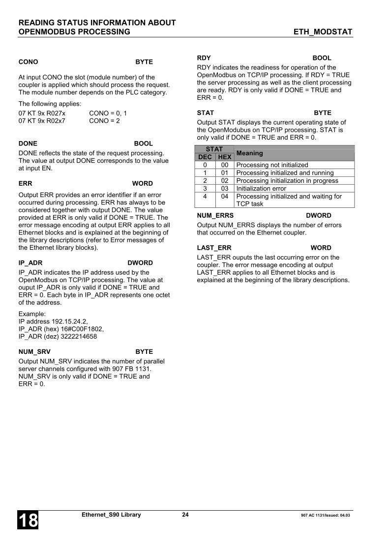
READING STATUS INFORMATION ABOUTOPENMODBUS PROCESSING ETH_MODSTAT
Ethernet_S90 Library 24 907 AC 1131/Issued: 04.0318
CONO BYTE
At input CONO the slot (module number) of thecoupler is applied which should process the request.The module number depends on the PLC category.
The following applies:07 KT 9x R027x CONO = 0, 107 KT 9x R02x7 CONO = 2
DONE BOOLDONE reflects the state of the request processing.The value at output DONE corresponds to the valueat input EN.
ERR WORDOutput ERR provides an error identifier if an erroroccurred during processing. ERR has always to beconsidered together with output DONE. The valueprovided at ERR is only valid if DONE = TRUE. Theerror message encoding at output ERR applies to allEthernet blocks and is explained at the beginning ofthe library descriptions (refer to Error messages ofthe Ethernet library blocks).
IP_ADR DWORDIP_ADR indicates the IP address used by theOpenModbus on TCP/IP processing. The value atouput IP_ADR is only valid if DONE = TRUE andERR = 0. Each byte in IP_ADR represents one octetof the address.
Example:IP address 192.15.24.2,IP_ADR (hex) 16#C00F1802,IP_ADR (dez) 3222214658
NUM_SRV BYTEOutput NUM_SRV indicates the number of parallelserver channels configured with 907 FB 1131.NUM_SRV is only valid if DONE = TRUE andERR = 0.
RDY BOOLRDY indicates the readiness for operation of theOpenModbus on TCP/IP processing. If RDY = TRUEthe server processing as well as the client processingare ready. RDY is only valid if DONE = TRUE andERR = 0.
STAT BYTEOutput STAT displays the current operating state ofthe OpenModubus on TCP/IP processing. STAT isonly valid if DONE = TRUE and ERR = 0.
STATDEC HEX Meaning
0 00 Processing not initialized1 01 Processing initialized and running2 02 Processing initialization in progress3 03 Initialization error4 04 Processing initialized and waiting for
TCP task
NUM_ERRS DWORDOutput NUM_ERRS displays the number of errorsthat occurred on the Ethernet coupler.
LAST_ERR WORDLAST_ERR ouputs the last occurring error on thecoupler. The error message encoding at outputLAST_ERR applies to all Ethernet blocks and isexplained at the beginning of the library descriptions.
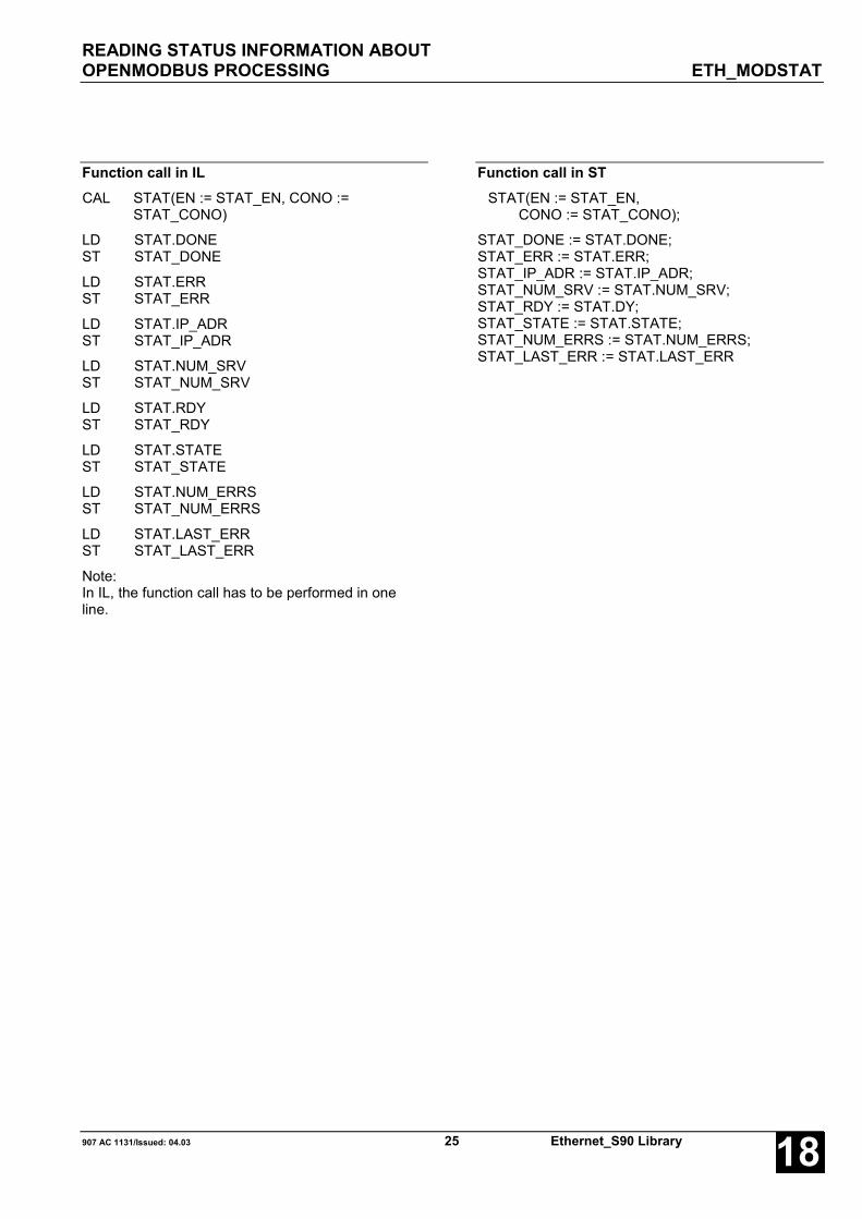
READING STATUS INFORMATION ABOUTOPENMODBUS PROCESSING ETH_MODSTAT
907 AC 1131/Issued: 04.03 25 Ethernet_S90 Library 18
Function call in ILCAL STAT(EN := STAT_EN, CONO :=
STAT_CONO)
LD STAT.DONEST STAT_DONE
LD STAT.ERRST STAT_ERR
LD STAT.IP_ADRST STAT_IP_ADR
LD STAT.NUM_SRVST STAT_NUM_SRV
LD STAT.RDYST STAT_RDY
LD STAT.STATEST STAT_STATE
LD STAT.NUM_ERRSST STAT_NUM_ERRS
LD STAT.LAST_ERRST STAT_LAST_ERR
Note:In IL, the function call has to be performed in oneline.
Function call in STSTAT(EN := STAT_EN,
CONO := STAT_CONO);
STAT_DONE := STAT.DONE;STAT_ERR := STAT.ERR;STAT_IP_ADR := STAT.IP_ADR;STAT_NUM_SRV := STAT.NUM_SRV;STAT_RDY := STAT.DY;STAT_STATE := STAT.STATE;STAT_NUM_ERRS := STAT.NUM_ERRS;STAT_LAST_ERR := STAT.LAST_ERR

PROCESSING OPENMODBUS ON TCP/IP CLIENT TELEGRAMS ETH_MODMAST
Ethernet_S90 Library 26 907 AC 1131/Issued: 04.0318
PROCESSING OPENMODBUS ON TCP/IP CLIENT TELEGRAMS ETH_MODMASTThe ETH_MODMAST block can be usedto send an OpenModbus on TCP/IPtelegram to a server (slave) and toprocess the corresponding response.
Block dataAvailable as of PLC runtime system: V5.0 Remark:Included in library: Ethernet_S90_V50.LIB
Block typeFunction block with historical values
ParametersInstance ETH_MODMAST Instance nameEN BOOL Enabling of the block processingCONO BYTE Slot (module number) of the couplerIP_ADR DWORD IP address of the serverFCT BYTE Modbus function codeADDR WORD Operand/register address in the serverNB WORD Number of the data to be read/writtenDATA DWORD Address of the first operand in the client from which data shall be written to the
server or where the data read from the server shall be storedDONE BOOL Ready message of the blockERR WORD Error message
DescriptionThe ETH_MODMAST block implements theOpenModbus on TCP/IP client functionality for theEthernet coupler specified at input CONO. Dependingon the configuration of the coupler, severalETH_MODMAST blocks can be used in parallel. Priorto the use of ETH_MODMAST for an Ethernet couplerthe coupler has to be configured accordingly by meansof 907 FB 1131.
With each FALSE -> TRUE edge at input EN, thefunction block ETH_MODMAST reads the values at theinputs, generates a telegram according to the inputsand then sends this telegram to the slave.
EN BOOLIf a FALSE -> TRUE edge is applied to input EN, allfurther inputs are read in. If the input values are valid, arequest telegram is sent to the specified server. If atleast one input is invalid, no telegram is generated andthe error is displayed at output ERR instead.
While the request is processed, state changes at inputEN are recognized but not evaluated.
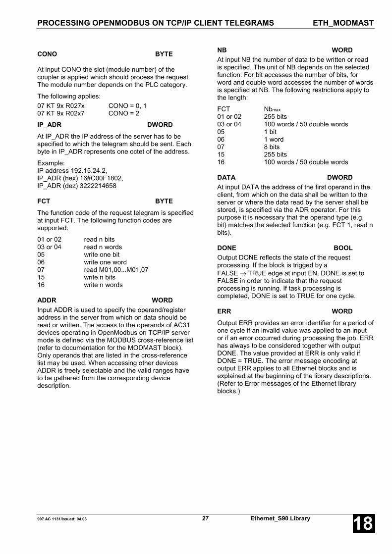
PROCESSING OPENMODBUS ON TCP/IP CLIENT TELEGRAMS ETH_MODMAST
907 AC 1131/Issued: 04.03 27 Ethernet_S90 Library 18
CONO BYTE
At input CONO the slot (module number) of thecoupler is applied which should process the request.The module number depends on the PLC category.
The following applies:07 KT 9x R027x CONO = 0, 107 KT 9x R02x7 CONO = 2
IP_ADR DWORDAt IP_ADR the IP address of the server has to bespecified to which the telegram should be sent. Eachbyte in IP_ADR represents one octet of the address.
Example:IP address 192.15.24.2,IP_ADR (hex) 16#C00F1802,IP_ADR (dez) 3222214658
FCT BYTEThe function code of the request telegram is specifiedat input FCT. The following function codes aresupported:
01 or 02 read n bits03 or 04 read n words05 write one bit06 write one word07 read M01,00...M01,0715 write n bits16 write n words
ADDR WORDInput ADDR is used to specify the operand/registeraddress in the server from which on data should beread or written. The access to the operands of AC31devices operating in OpenModbus on TCP/IP servermode is defined via the MODBUS cross-reference list(refer to documentation for the MODMAST block).Only operands that are listed in the cross-referencelist may be used. When accessing other devicesADDR is freely selectable and the valid ranges haveto be gathered from the corresponding devicedescription.
NB WORDAt input NB the number of data to be written or readis specified. The unit of NB depends on the selectedfunction. For bit accesses the number of bits, forword and double word accesses the number of wordsis specified at NB. The following restrictions apply tothe length:
FCT Nbmax
01 or 02 255 bits03 or 04 100 words / 50 double words05 1 bit06 1 word07 8 bits15 255 bits16 100 words / 50 double words
DATA DWORDAt input DATA the address of the first operand in theclient, from which on the data shall be written to theserver or where the data read by the server shall bestored, is specified via the ADR operator. For thispurpose it is necessary that the operand type (e.g.bit) matches the selected function (e.g. FCT 1, read nbits).
DONE BOOLOutput DONE reflects the state of the requestprocessing. If the block is trigged by aFALSE → TRUE edge at input EN, DONE is set toFALSE in order to indicate that the requestprocessing is running. If task processing iscompleted, DONE is set to TRUE for one cycle.
ERR WORDOutput ERR provides an error identifier for a period ofone cycle if an invalid value was applied to an inputor if an error occurred during processing the job. ERRhas always to be considered together with outputDONE. The value provided at ERR is only valid ifDONE = TRUE. The error message encoding atoutput ERR applies to all Ethernet blocks and isexplained at the beginning of the library descriptions.(Refer to Error messages of the Ethernet libraryblocks.)

PROCESSING OPENMODBUS ON TCP/IP CLIENT TELEGRAMS ETH_MODMAST
Ethernet_S90 Library 28 907 AC 1131/Issued: 04.0318
Function call in ILLD MAST_DATAADRST MAST.DATA
CAL MAST(EN := MAST_EN,CONO := MAST_CONO,IP_ADR := MAST_IP_ADR,FCT := MAST_FCT,ADDR := MAST_ADDR,NB := MAST_NB,DATA := MAST_DATA)
LD MAST.DONEST MAST_DONE
LD MAST.ERRST MAST_ERR
Note:In IL, the function call has to be performed in oneline.
Function call in STMAST(EN := MAST_EN,
CONO := MAST_CONO,IP_ADR := MAST_IP_ADR,FCT := MAST_FCT,ADDR := MAST_ADDR,NB := MAST_NB,DATA := ADR(MAST_DATA),);
MAST_DONE := MAST.DONE;MAST_ERR := MAST.ERR;
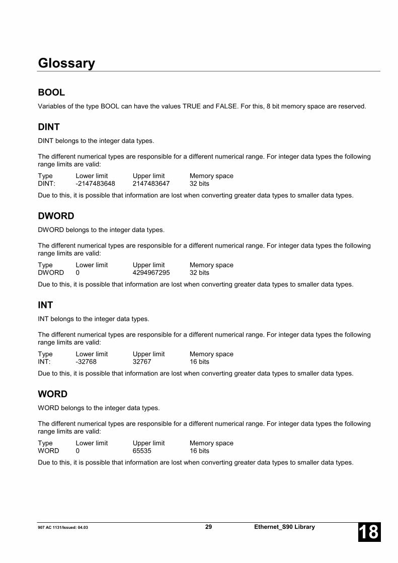
907 AC 1131/Issued: 04.03 29 Ethernet_S90 Library 18
Glossary
BOOLVariables of the type BOOL can have the values TRUE and FALSE. For this, 8 bit memory space are reserved.
DINTDINT belongs to the integer data types.
The different numerical types are responsible for a different numerical range. For integer data types the followingrange limits are valid:
Type Lower limit Upper limit Memory spaceDINT: -2147483648 2147483647 32 bits
Due to this, it is possible that information are lost when converting greater data types to smaller data types.
DWORDDWORD belongs to the integer data types.
The different numerical types are responsible for a different numerical range. For integer data types the followingrange limits are valid:
Type Lower limit Upper limit Memory spaceDWORD 0 4294967295 32 bits
Due to this, it is possible that information are lost when converting greater data types to smaller data types.
INTINT belongs to the integer data types.
The different numerical types are responsible for a different numerical range. For integer data types the followingrange limits are valid:
Type Lower limit Upper limit Memory spaceINT: -32768 32767 16 bits
Due to this, it is possible that information are lost when converting greater data types to smaller data types.
WORDWORD belongs to the integer data types.
The different numerical types are responsible for a different numerical range. For integer data types the followingrange limits are valid:
Type Lower limit Upper limit Memory spaceWORD 0 65535 16 bits
Due to this, it is possible that information are lost when converting greater data types to smaller data types.
Ethernet_S90 Library 30 907 AC 1131/Issued: 04.0318
FunctionsFunctions are subroutines which have multiple input parameters and return exactly one result element. Thereturned result can be of an elementary or a derived data type. Due to this, a function may also return an array, astructure, an array of structures and so on.
For the same input parameters, functions always return the same result (they do not have an internal memory).
Therefore, the following rules can be derived:
• Within functions, global variables can neither be read nor written.• Within functions, absolute operands can neither be read nor written.• Within functions, function blocks must not be called.
Function blocksFunction blocks are subroutines which can have as many inputs, outputs and internal variables as required. Theyare called from a program or from another function block.
As they can be used several times (with different data records), function blocks (code and interface) can beconsidered as type. When assigning an individual data record (declaration) to the function block, a function blockinstance is generated.
In contrast to functions, function blocks can contain statically local data which are saved from one call to the next.Therefore e.g. counters can be realized which may not forget their counter value. I.e. function blocks can have aninternal memory.
Functions and function blocks differ in two essential points:
• A function block has multiple output parameters, a function only one.The output parameters of functions and function blocks differ syntactically.
• In contrast to a function, a function block can have an internal memory.
1. Function blocks with historical values (memory):
For function blocks with historical values it has to be observed that instance names may not be defined severaltimes if different data sets should be called.
2. Function blocks without historical values (memory):
For function blocks without historical values only one instance has to be defined for the FB type. This instance canbe used for several calls of the FB (also with different I/O values).
The instance name can be defined without any restrictions. The type is preset and identical to the function blockname.

907 AC 1131/Issued: 04.03 31 Ethernet_S90 Library 18
Index
CComponents of the Ethernet library 2
EETH_AINIT S90 9
ETH_AREC S90 14
ETH_ASEND S90 17
ETH_ASTO S90 20
ETH_INFO S90 7
ETH_MODMAST S90 26
ETH_MODSTAT S90 23
Ethernet S90
ETH_AINIT 9
ETH_AREC 14
ETH_ASEND 17
ETH_ASTO 20
ETH_INFO 7
ETH_MODMAST 26
ETH_MODSTAT 23

Ethernet_S90 Library 32 907 AC 1131/Issued: 04.0318


ABB STOTZ-KONTAKT GmbHEppelheimer Straße 82 Postfach 10168069123 Heidelberg 69006 HeidelbergGermany Germany
Telephone +49 6221 701-0Telefax +49 6221 701-240E-Mail [email protected] http://www.abb.de/stotz-kontakt
Man
ual N
o.:
2CD
C 1
20 0
68 M
020
2