software design strategies for multidisciplinary ... seventh international conference on...
TRANSCRIPT
1
Seventh International Conference on Computational Fluid Dynamics (ICCFD7), Big Island, Hawaii, July 9-13, 2012
ICCFD7-1601
Software Design Strategies for Multidisciplinary Computational
Fluid Dynamics
Roger C. Strawn*
Corresponding author: [email protected]
*US Army Aeroflightdynamics Directorate, AMRDEC, Moffett Field, CA, USA
Abstract: The multidisciplinary nature of rotary-wing aeromechanics poses a
daunting challenge for the design of practical modeling and simulation software
that is accurate, efficient, and maintainable. This paper describes the design
strategy for the US Army’s Helios software, which features a lightweight Python-
language integration framework combined with well-defined interfaces to link
together various multidisciplinary software components. This design facilitates the
use of alternative component software within Helios, the addition of new
component software into Helios, and the rapid introduction of new computational
fluid dynamics technology within Helios. This paper also presents examples of
Helios rotary-wing aeromechanics simulations that include simultaneous solutions
for rotor dynamics and aerodynamics plus high resolution of the rotor wake system.
Keywords: Rotary-wing vehicles, Computational fluid dynamics, Python language,
Computational aeromechanics.
1 Introduction
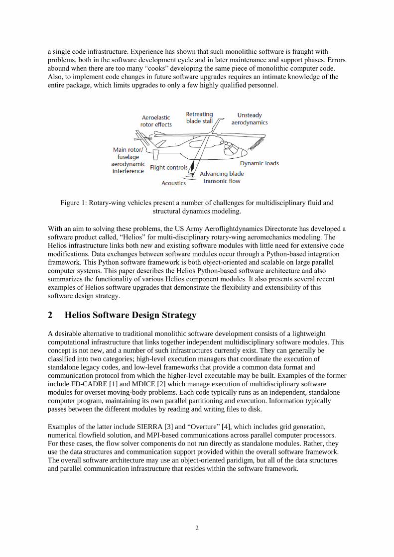
As Figure 1 shows, helicopter flight involves many multidisciplinary physics problems that are
difficult to predict with today’s engineering modeling and simulation tools. Rotor aerodynamic
systems involve complex interactions among the rotor blades, rotor wakes, and fuselage, and they
create challenges such as
simultaneous modeling of rotating and nonrotating components;
retreating-blade low-speed dynamic stall;
advancing-blade transonic flow;
rotor “trim” requirements to balance aerodynamic and dynamic forces for particular control
settings; and
a strong coupling between rotor-blade aerodynamics and rotor blade dynamics (both rigid and
elastic blade motion).
A successful rotorcraft aeromechanics simulation must accurately represent all these physical
phenomena. These software models typically require substantial engineering expertise, powerful
computer systems, and must couple computational fluid dynamics (CFD), computational structural
dynamics (CSD), and vehicle flight controls.
This multidisciplinary nature for rotorcraft poses a daunting task for designing practical modeling and
simulation software that is accurate, efficient, and maintainable. Traditional rotary-wing modeling and
simulation software tends to be monolithic, combining all of the multidisciplinary physics models into
Report Documentation Page Form ApprovedOMB No. 0704-0188
Public reporting burden for the collection of information is estimated to average 1 hour per response, including the time for reviewing instructions, searching existing data sources, gathering andmaintaining the data needed, and completing and reviewing the collection of information. Send comments regarding this burden estimate or any other aspect of this collection of information,including suggestions for reducing this burden, to Washington Headquarters Services, Directorate for Information Operations and Reports, 1215 Jefferson Davis Highway, Suite 1204, ArlingtonVA 22202-4302. Respondents should be aware that notwithstanding any other provision of law, no person shall be subject to a penalty for failing to comply with a collection of information if itdoes not display a currently valid OMB control number.
1. REPORT DATE JUL 2012 2. REPORT TYPE
3. DATES COVERED 00-00-2012 to 00-00-2012
4. TITLE AND SUBTITLE Software Design Strategies for Multidisciplinary Computational Fluid Dynamics
5a. CONTRACT NUMBER
5b. GRANT NUMBER
5c. PROGRAM ELEMENT NUMBER
6. AUTHOR(S) 5d. PROJECT NUMBER
5e. TASK NUMBER
5f. WORK UNIT NUMBER
7. PERFORMING ORGANIZATION NAME(S) AND ADDRESS(ES) AMRDEC,US Army Aeroflightdynamics Directorate,Moffett Field,CA,94035
8. PERFORMING ORGANIZATIONREPORT NUMBER
9. SPONSORING/MONITORING AGENCY NAME(S) AND ADDRESS(ES) 10. SPONSOR/MONITOR’S ACRONYM(S)
11. SPONSOR/MONITOR’S REPORT NUMBER(S)
12. DISTRIBUTION/AVAILABILITY STATEMENT Approved for public release; distribution unlimited
13. SUPPLEMENTARY NOTES Presented at the Seventh International Conference on Computational Fluid Dynamics (ICCFD7), BigIsland, Hawaii, July 9-13, 2012,Government or Federal Purpose Rights License
14. ABSTRACT The multidisciplinary nature of rotary-wing aeromechanics poses a daunting challenge for the design ofpractical modeling and simulation software that is accurate, efficient, and maintainable. This paperdescribes the design strategy for the US Army?s Helios software, which features a lightweightPython-language integration framework combined with well-defined interfaces to link together variousmultidisciplinary software components. This design facilitates the use of alternative component softwarewithin Helios, the addition of new component software into Helios, and the rapid introduction of newcomputational fluid dynamics technology within Helios. This paper also presents examples of Heliosrotary-wing aeromechanics simulations that include simultaneous solutions for rotor dynamics andaerodynamics plus high resolution of the rotor wake system.
15. SUBJECT TERMS
16. SECURITY CLASSIFICATION OF: 17. LIMITATION OF ABSTRACT Same as
Report (SAR)
18. NUMBEROF PAGES
16
19a. NAME OFRESPONSIBLE PERSON
a. REPORT unclassified
b. ABSTRACT unclassified
c. THIS PAGE unclassified
Standard Form 298 (Rev. 8-98) Prescribed by ANSI Std Z39-18
2
a single code infrastructure. Experience has shown that such monolithic software is fraught with
problems, both in the software development cycle and in later maintenance and support phases. Errors
abound when there are too many “cooks” developing the same piece of monolithic computer code.
Also, to implement code changes in future software upgrades requires an intimate knowledge of the
entire package, which limits upgrades to only a few highly qualified personnel.
Figure 1: Rotary-wing vehicles present a number of challenges for multidisciplinary fluid and
structural dynamics modeling.
With an aim to solving these problems, the US Army Aeroflightdynamics Directorate has developed a
software product called, “Helios” for multi-disciplinary rotary-wing aeromechanics modeling. The
Helios infrastructure links both new and existing software modules with little need for extensive code
modifications. Data exchanges between software modules occur through a Python-based integration
framework. This Python software framework is both object-oriented and scalable on large parallel
computer systems. This paper describes the Helios Python-based software architecture and also
summarizes the functionality of various Helios component modules. It also presents several recent
examples of Helios software upgrades that demonstrate the flexibility and extensibility of this
software design strategy.
2 Helios Software Design Strategy
A desirable alternative to traditional monolithic software development consists of a lightweight
computational infrastructure that links together independent multidisciplinary software modules. This
concept is not new, and a number of such infrastructures currently exist. They can generally be
classified into two categories; high-level execution managers that coordinate the execution of
standalone legacy codes, and low-level frameworks that provide a common data format and
communication protocol from which the higher-level executable may be built. Examples of the former
include FD-CADRE [1] and MDICE [2] which manage execution of multidisciplinary software
modules for overset moving-body problems. Each code typically runs as an independent, standalone
computer program, maintaining its own parallel partitioning and execution. Information typically
passes between the different modules by reading and writing files to disk.
Examples of the latter include SIERRA [3] and “Overture” [4], which includes grid generation,
numerical flowfield solution, and MPI-based communications across parallel computer processors.
For these cases, the flow solver components do not run directly as standalone modules. Rather, they
use the data structures and communication support provided within the overall software framework.
The overall software architecture may use an object-oriented paridigm, but all of the data structures
and parallel communication infrastructure that resides within the software framework.
3
Both the low and high-level approaches have their advantages and disadvantages. The high-level
approach has the advantage that it requires little change to existing legacy codes. However, the cost of
the file-based data exchange typically limits the efficiency and parallel scalability of the coupled
codes during execution. Also, these high-level coupling approaches typically lack granularity in their
standalone legacy software components, which tends to limit software changes in these legacy
components to only a few highly qualified personnel who are familiar with that legacy software
package.
The low-level approach circumvents this problem by exchanging information between modules
within the framework itself. Additionally, it encourages the use of common algorithms and load
balancing strategies across multiple codes. However, the addition of low-level multidisciplinary
functionality to the existing solver typically requires substantial rewrites of these new software
modules in order to implement the data structures and communication protocols that are supported by
the framework. Also, low-level coupling approaches may be less flexible than their high-level
counterparts due to predetermined requirements for data structures and/or computational meshing
strategies. More importantly, it is hard to coordinate teams of software developers to work on these
integrated software packages since these software developers have a limited ability to work
independently.
Helios uses an intermediate-level software infrastructure described in Refs. [5-7] that uses
characteristics from both of the approaches described above. Like the high-level execution managers,
it links existing software modules with little need for extensive code modifications. However, instead
of using file transfers for data exchanges between modules, data exchanges between software modules
take place through a top-layer Python-language integration framework that is both object-oriented and
scalable. The Python top layer facilitates data exchanges between individual multidisciplinary
component software modules and these data exchanges occur through direct memory access rather
than file input and output (I/O). As such, the Helios Python framework provides simple data transfers
among software component modules with sufficient granularity to ensure that groups of programmers
can work independently on each of many multi-disciplinary software component modules and then
easily use Python to tie them together in order to create the final software product.
Python-language programming for multidisciplinary scientific computing is well suited for integrating
legacy and newly-developed software, software written in multiple languages, and for implementing
multidisciplinary component software modules in an object-oriented manner. Python’s advantages are
well documented in Ref. [8], which is part of an entire journal issue devoted to Python programming.
In this paper, the author states that, “Python is an excellent “steering” language for scientific codes
written in other languages.” The author also makes the point that, “You can embed Python into an
existing application, which means you can instantly add an easy-to-use veneer on top of an older,
trusted application.”
Other researchers have shown success with similar approaches. For example, Alonso et al. [9] have
previously used such a Python-based infrastructure for multi-disciplinary design optimization. They
also developed this Python framework for the prediction of helicopter noise and the Python
integration framework from this effort served as an initial template for the current Helios approach. In
addition, Schluter et al. [10] demonstrated a coupled large-eddy simulation and Reynolds-Averaged
Navier-Stokes (RANS) fluid dynamics simulations on large-scale parallel computer systems with a
similar infrastructure. Finally, Gopalan et al. [11] have used this paradigm for multi-disciplinary
simulations consisting of CFD, CSD, and acoustic codes applied to helicopter aeromechanics and
noise.
The Python-language-based approach has the desirable feature that allows each software module to be
treated as an object, providing a convenient way to assemble a complex multidisciplinary simulation
in an object-oriented fashion. This ability to effectively use legacy software modules results in
reduced development time with reduced software maintenance. In addition, it provides flexibility by
4
allowing for the use of multiple interchangeable software modules. As a result, Helios software
developers can readily extend their own software and leverage the work of others by allowing new
components to “plug in” in place of others.
The Python infrastructure orchestrates specific operations in the solvers by making calls through a
socket-like interface layer, which also manages the translation of data between Python and the native
language (e.g. C or FORTRAN) of the component solvers. Data exchanges can be done without
memory copies or file I/O, and the infrastructure can be run in parallel on large multi-processor
computer systems. The Python interfaces are only used only at a high-level; primarily for exchanging
data and not for numerical computing. This practice ensures that the Python layer introduces minimal
computational overhead, thus retaining the original computational efficiency of each of the building-
block software modules.
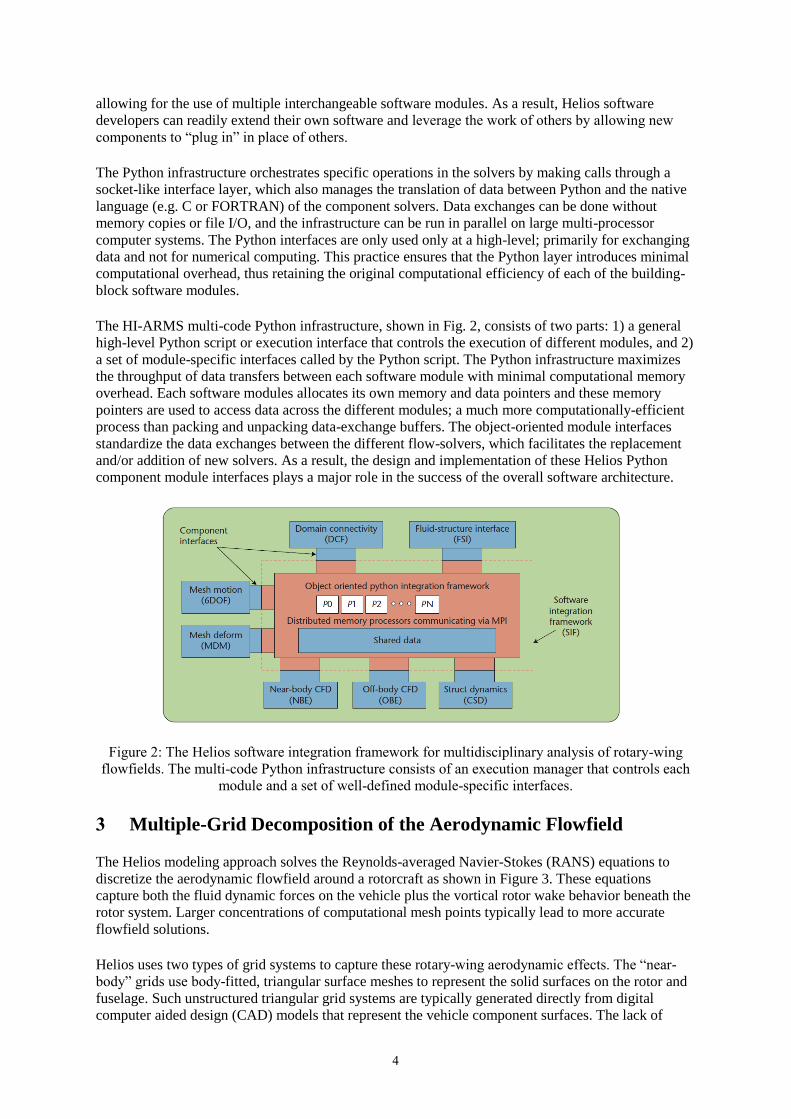
The HI-ARMS multi-code Python infrastructure, shown in Fig. 2, consists of two parts: 1) a general
high-level Python script or execution interface that controls the execution of different modules, and 2)
a set of module-specific interfaces called by the Python script. The Python infrastructure maximizes
the throughput of data transfers between each software module with minimal computational memory
overhead. Each software modules allocates its own memory and data pointers and these memory
pointers are used to access data across the different modules; a much more computationally-efficient
process than packing and unpacking data-exchange buffers. The object-oriented module interfaces
standardize the data exchanges between the different flow-solvers, which facilitates the replacement
and/or addition of new solvers. As a result, the design and implementation of these Helios Python
component module interfaces plays a major role in the success of the overall software architecture.
Figure 2: The Helios software integration framework for multidisciplinary analysis of rotary-wing
flowfields. The multi-code Python infrastructure consists of an execution manager that controls each
module and a set of well-defined module-specific interfaces.
3 Multiple-Grid Decomposition of the Aerodynamic Flowfield
The Helios modeling approach solves the Reynolds-averaged Navier-Stokes (RANS) equations to
discretize the aerodynamic flowfield around a rotorcraft as shown in Figure 3. These equations
capture both the fluid dynamic forces on the vehicle plus the vortical rotor wake behavior beneath the
rotor system. Larger concentrations of computational mesh points typically lead to more accurate
flowfield solutions.
Helios uses two types of grid systems to capture these rotary-wing aerodynamic effects. The “near-
body” grids use body-fitted, triangular surface meshes to represent the solid surfaces on the rotor and
fuselage. Such unstructured triangular grid systems are typically generated directly from digital
computer aided design (CAD) models that represent the vehicle component surfaces. The lack of
5
ordered structure for these triangular grids provides a high degree of generality and flexibility to
resolve complicated surface geometries.
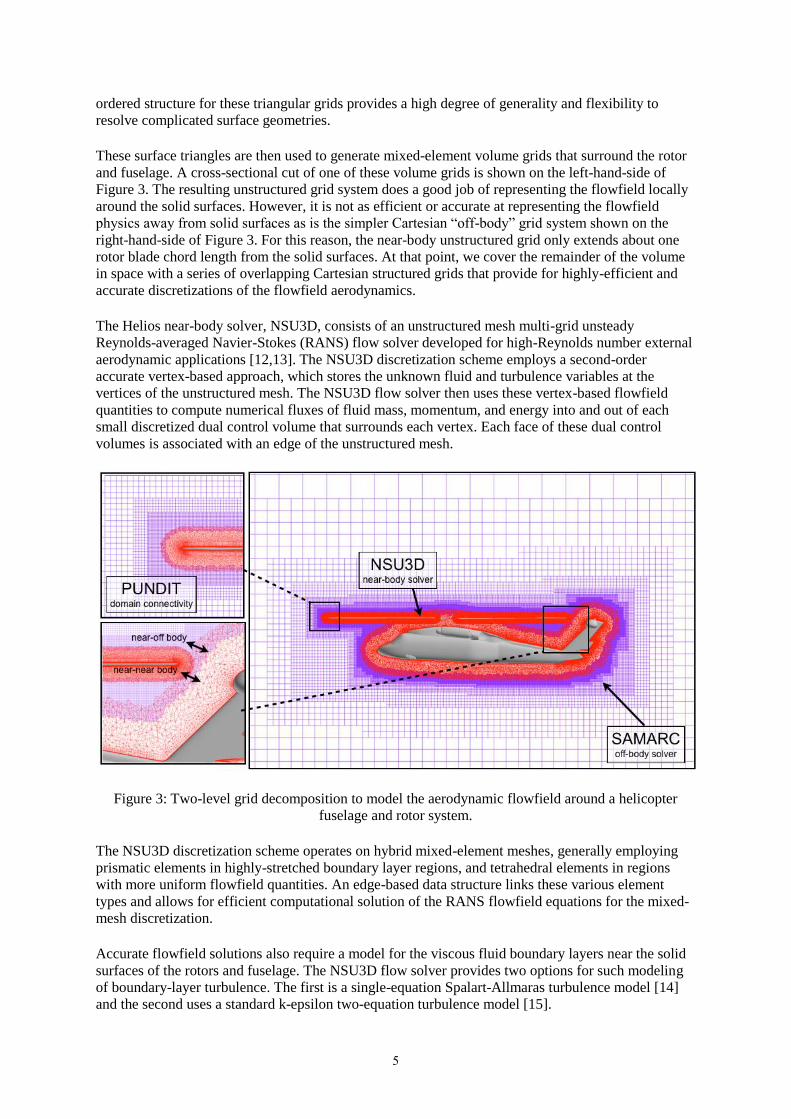
These surface triangles are then used to generate mixed-element volume grids that surround the rotor
and fuselage. A cross-sectional cut of one of these volume grids is shown on the left-hand-side of
Figure 3. The resulting unstructured grid system does a good job of representing the flowfield locally
around the solid surfaces. However, it is not as efficient or accurate at representing the flowfield
physics away from solid surfaces as is the simpler Cartesian “off-body” grid system shown on the
right-hand-side of Figure 3. For this reason, the near-body unstructured grid only extends about one
rotor blade chord length from the solid surfaces. At that point, we cover the remainder of the volume
in space with a series of overlapping Cartesian structured grids that provide for highly-efficient and
accurate discretizations of the flowfield aerodynamics.
The Helios near-body solver, NSU3D, consists of an unstructured mesh multi-grid unsteady
Reynolds-averaged Navier-Stokes (RANS) flow solver developed for high-Reynolds number external
aerodynamic applications [12,13]. The NSU3D discretization scheme employs a second-order
accurate vertex-based approach, which stores the unknown fluid and turbulence variables at the
vertices of the unstructured mesh. The NSU3D flow solver then uses these vertex-based flowfield
quantities to compute numerical fluxes of fluid mass, momentum, and energy into and out of each
small discretized dual control volume that surrounds each vertex. Each face of these dual control
volumes is associated with an edge of the unstructured mesh.
Figure 3: Two-level grid decomposition to model the aerodynamic flowfield around a helicopter
fuselage and rotor system.
The NSU3D discretization scheme operates on hybrid mixed-element meshes, generally employing
prismatic elements in highly-stretched boundary layer regions, and tetrahedral elements in regions
with more uniform flowfield quantities. An edge-based data structure links these various element
types and allows for efficient computational solution of the RANS flowfield equations for the mixed-
mesh discretization.
Accurate flowfield solutions also require a model for the viscous fluid boundary layers near the solid
surfaces of the rotors and fuselage. The NSU3D flow solver provides two options for such modeling
of boundary-layer turbulence. The first is a single-equation Spalart-Allmaras turbulence model [14]
and the second uses a standard k-epsilon two-equation turbulence model [15].
6
The off-body Cartesian flow solver is built from the Structured Adaptive Mesh Refinement
Applications Infrastructure (SAMRAI) library originally developed at Lawrence Livermore National
Laboratory [16–19]. It uses Cartesian block structured grids, which lead to a substantially more
efficient computational execution compared to the unstructured near-body flow solver described
above. The disadvantage to the Cartesian solver is that it cannot easily represent the viscous flowfield
around complex surfaces geometries. However, Helios only uses the Cartesian flow solver away from
solid surfaces so that conformance to complicated geometries is not an issue. The Cartesian grid
generation, load balancing, and parallel adaptive data exchanges between blocks in the off-body
solver are all performed by the basic SAMRAI infrastructure. A dedicated Cartesian flow solver
derived from the ARC3D code [20] computes the solution on each Cartesian grid block. It uses an
explicit 3rd order Runge-Kutta time-integration scheme and has spatial differencing options ranging
from second- to fifth-order order accurate. In this sense, the core ARC3DC flow solver functions as a
module library within the SAMRAI infrastructure. The resulting combination of SAMRAI mesh
management and ARC3D flow solver is referred to as SAMARC.
The near-body and off-body grid systems overlap in space and communication between the two grid
systems takes place within this overlap region. A software module called PUNDIT [21] coordinates
the data transfer between different solvers applied in different parts of the computational domain. The
body-fitted unstructured solver captures the viscous near-wall effects, and the Cartesian solvers with
high-order accurate differencing scheme captures the rotor wake regions in the off-body meshes. The
PUNDIT module provides a new domain connectivity capability for performing the interpolation and
data exchange between these overlapping grid systems. The PUNDIT domain-connectivity module is
fully parallel and performs all its operations (identification of holes and fringe points, donor cell
searches and data interpolation) on the partitioned-grid data. In addition, the connectivity procedures
are completely automated using an implicit hole-cutting methodology that requires no user
intervention to match the overlap regions between adjacent grid systems.
4 Coupling between Rotor Aerodynamics and Rotor Dynamics
Rotor blades typically move in response to a number of different forces including:
1) The torque to the rotor system from the engine
2) The rotor control system inputs set by the pilot.
3) Structural dynamic body forces such as centrifugal accelerations
4) Aerodynamic lift, drag and pitching moment forces on the rotor
The above forces on the rotor result in both rigid and elastic rotor motions that are tightly coupled to
the aerodynamic forces on the rotor system. For and articulated rotor, rigid rotor motions include
blade flap, lead-lag, and pitch. Elastic motions include rotor-blade bending and torsion. Accurate
modeling of all these rotor motions is crucial to the successful aeromechanic performance-prediction
for helicopter systems. For a helicopter to fly straight and level, all of the above forces on the rotor
must be balanced and this state is known as helicopter trim. Computational modeling of a trimmed
rotor state requires the simultaneous coupled modeling of the rotor aerodynamic forces and rotor
structural dynamic response.
Rotor structural dynamics and trim modeling is handled by the Rotorcraft Comprehensive Analysis
System (RCAS) [22]. The RCAS rotorcraft comprehensive analysis model has been developed and
maintained by US Army Aeroflightdynamics Directorate in partnership with Advanced Rotorcraft
Technology Inc. (ART) over the past 20 years. RCAS supplies the rotor structural dynamics model,
the rotor trim model, and the coupling model between the fluid and structural dynamics.
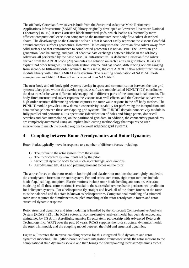
Figure 4 illustrates the iterative coupling process for this integrated fluid dynamics and rotor
dynamics modeling. The Python-based software integration framework sends the rotor motions to the
computational fluid dynamics solvers and then brings the corresponding rotor aerodynamics forces
7
back to the computational structural dynamics model. At the end of a trimmed rotor computation, the
aerodynamic forces on the rotor are consistent with the rotor dynamic motions and also with the pilot
control inputs.
The rotor fluid structure interface model takes the three-dimensional surface patch forces from the
near-body computational fluid dynamics solver (NSU3D) and imposes these forces on the RCAS
model for the rotor structural dynamics. The fluid-structure interface ensures that these imposed
forces conserve energy for the RCAS one-dimensional, non-linear beam structural dynamics model
while also preserving the total airloads forces. The fluid-structure interface is generic to structured or
unstructured grids for the computational fluid dynamics (CFD) flow solver and there is no
requirement for sectional airloads to be calculated as an intermediate step in the CFD. Each and every
surface patch force is imposed directly on the structure consistent with the high-fidelity CFD solution.
The fluid-structure interface also ensures consistency of the geometry and reference frames between
the CFD and CSD solvers. Wissink et al. [23] present more detailed descriptions of both these and
other features in the most recent Helios version 3 software release.
Figure 4: Iterative coupling cycle between rotor computational structural and rotor computational
fluid dynamics. The dynamics module provides the rotor motions and the aerodynamic model
provides the rotor aerodynamic forces.
5 Rotary-Wing Aeromechanics Modeling for the HART-II Rotor
System
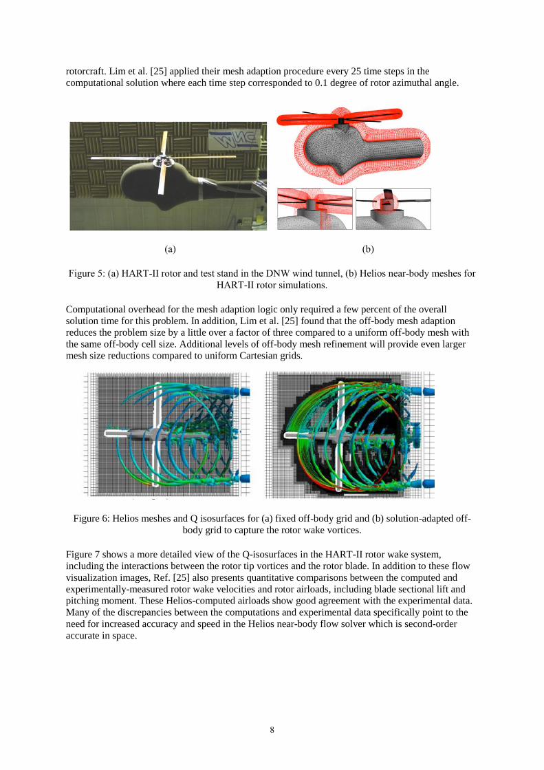
The HART II rotor is a 40% Mach and dynamically scaled model of Bo105 hingeless rotor that was
experimentally tested in the DNW wind tunnel in 2001 as part of an international cooperative research
effort [24]. Figure 5(a) shows a photograph of the HART-II rotor and wind tunnel test stand.
Lim et al. [25] recently performed Helios simulations for a number of the HART-II experimental test
conditions and their results highlight many of the new features in Helios version 3. These Helios
computations for this test used a total of 12.6 million nodes for the HART-II near-body grid system
around the rotor and test stand shown in Figure 5(b).
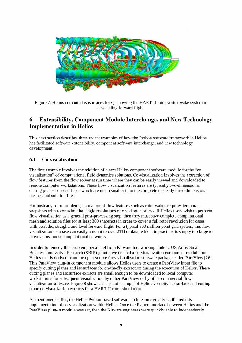
The Helios Cartesian off-body meshes grids used adaptive mesh refinement to identify and
dynamically refine the computational grid around the rotor tip vortices with a maximum of about 200
million mesh points in the final computation. Figure 6 shows a snapshot of the “Q” isosurfaces for
two of these off-body meshes, where “Q” is a scaled measure of the rotational component of the
vorticity vector. Figure 6(a) shows a solution for a fixed off-body grid with a uniform spacing equal to
0.1 rotor blade chord lengths. Figure 6(b) shows a dynamically-adapted grid where the finest mesh
spacing is equal to 0.025 rotor blade chord lengths. The adaptive mesh solution for the HART-II rotor
wake shows much improved resolution of the rotor vortex wake system, which is important for
computing the aerodynamic effects of vortex interactions with the rotor and fuselage in realistic
8
rotorcraft. Lim et al. [25] applied their mesh adaption procedure every 25 time steps in the
computational solution where each time step corresponded to 0.1 degree of rotor azimuthal angle.
(a) (b)
Figure 5: (a) HART-II rotor and test stand in the DNW wind tunnel, (b) Helios near-body meshes for
HART-II rotor simulations.
Computational overhead for the mesh adaption logic only required a few percent of the overall
solution time for this problem. In addition, Lim et al. [25] found that the off-body mesh adaption
reduces the problem size by a little over a factor of three compared to a uniform off-body mesh with
the same off-body cell size. Additional levels of off-body mesh refinement will provide even larger
mesh size reductions compared to uniform Cartesian grids.
Figure 6: Helios meshes and Q isosurfaces for (a) fixed off-body grid and (b) solution-adapted off-
body grid to capture the rotor wake vortices.
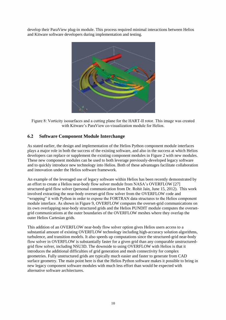
Figure 7 shows a more detailed view of the Q-isosurfaces in the HART-II rotor wake system,
including the interactions between the rotor tip vortices and the rotor blade. In addition to these flow
visualization images, Ref. [25] also presents quantitative comparisons between the computed and
experimentally-measured rotor wake velocities and rotor airloads, including blade sectional lift and
pitching moment. These Helios-computed airloads show good agreement with the experimental data.
Many of the discrepancies between the computations and experimental data specifically point to the
need for increased accuracy and speed in the Helios near-body flow solver which is second-order
accurate in space.
9
Figure 7: Helios computed isosurfaces for Q, showing the HART-II rotor vortex wake system in
descending forward flight.
6 Extensibility, Component Module Interchange, and New Technology
Implementation in Helios
This next section describes three recent examples of how the Python software framework in Helios
has facilitated software extensibility, component software interchange, and new technology
development.
6.1 Co-visualization
The first example involves the addition of a new Helios component software module for the “co-
visualization” of computational fluid dynamics solutions. Co-visualization involves the extraction of
flow features from the flow solver at run time where they can be easily viewed and downloaded to
remote computer workstations. These flow visualization features are typically two-dimensional
cutting planes or isosurfaces which are much smaller than the complete unsteady three-dimensional
meshes and solution files.
For unsteady rotor problems, animation of flow features such as rotor wakes requires temporal
snapshots with rotor azimuthal angle resolutions of one degree or less. If Helios users wish to perform
flow visualization as a general post-processing step, then they must save complete computational
mesh and solution files for at least 360 snapshots in order to cover a full rotor revolution for cases
with periodic, straight, and level forward flight. For a typical 300 million point grid system, this flow-
visualization database can easily amount to over 2TB of data, which, in practice, is simply too large to
move across most computational networks.
In order to remedy this problem, personnel from Kitware Inc. working under a US Army Small
Business Innovative Research (SBIR) grant have created a co-visualization component module for
Helios that is derived from the open-source flow visualization software package called ParaView [26].
This ParaView plug-in component module allows Helios users to create a ParaView input file to
specify cutting planes and isosurfaces for on-the-fly extraction during the execution of Helios. These
cutting planes and isosurface extracts are small enough to be downloaded to local computer
workstations for subsequent visualization by either ParaView or by other commercial flow
visualization software. Figure 8 shows a snapshot example of Helios vorticity iso-surface and cutting
plane co-visualization extracts for a HART-II rotor simulation.
As mentioned earlier, the Helios Python-based software architecture greatly facilitated this
implementation of co-visualization within Helios. Once the Python interface between Helios and the
ParaView plug-in module was set, then the Kitware engineers were quickly able to independently
10
develop their ParaView plug-in module. This process required minimal interactions between Helios
and Kitware software developers during implementation and testing.
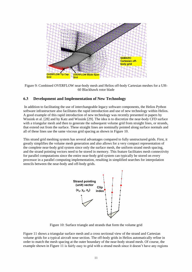
Figure 8: Vorticity isosurfaces and a cutting plane for the HART-II rotor. This image was created
with Kitware’s ParaView co-visualization module for Helios.
6.2 Software Component Module Interchange
As stated earlier, the design and implementation of the Helios Python component module interfaces
plays a major role in both the success of the existing software, and also in the success at which Helios
developers can replace or supplement the existing component modules in Figure 2 with new modules.
These new component modules can be used to both leverage previously-developed legacy software
and to quickly introduce new technology into Helios. Both of these advantages facilitate collaboration
and innovation under the Helios software framework.
An example of the leveraged use of legacy software within Helios has been recently demonstrated by
an effort to create a Helios near-body flow solver module from NASA’s OVERFLOW [27]
structured-grid flow solver (personal communication from Dr. Rohit Jain, June 15, 2012). This work
involved extracting the near-body overset-grid flow solver from the OVERFLOW code and
“wrapping” it with Python in order to expose the FORTRAN data structures to the Helios component
module interface. As shown in Figure 9, OVERFLOW computes the overset-grid communications on
its own overlapping near-body structured grids and the Helios PUNDIT module computes the overset-
grid communications at the outer boundaries of the OVERFLOW meshes where they overlap the
outer Helios Cartesian grids.
This addition of an OVERFLOW near-body flow solver option gives Helios users access to a
substantial amount of existing OVERFLOW technology including high-accuracy solution algorithms,
turbulence, and transition models. It also speeds up computations since the structured-grid near-body
flow solver in OVERFLOW is substantially faster for a given grid than any comparable unstructured-
grid flow solver, including NSU3D. The downside to using OVERFLOW with Helios is that it
introduces the additional difficulties of grid generation and mesh connectivity for complex
geometries. Fully unstructured grids are typically much easier and faster to generate from CAD
surface geometry. The main point here is that the Helios Python software makes it possible to bring in
new legacy component software modules with much less effort than would be expected with
alternative software architectures.
11
Figure 9: Combined OVERFLOW near-body mesh and Helios off-body Cartesian meshes for a UH-
60 Blackhawk rotor blade
6.3 Development and Implementation of New Technology
In addition to facilitating the use of interchangeable legacy software components, the Helios Python
software infrastructure also facilitates the rapid introduction and use of new technology within Helios.
A good example of this rapid introduction of new technology was recently presented in papers by
Wissink et al. [28] and by Katz and Wissink [29]. The idea is to discretize the near-body CFD surface
with a triangular mesh and then to generate the subsequent volume grid from straight lines, or strands,
that extend out from the surface. These straight lines are nominally pointed along surface normals and
all of these lines use the same viscous grid spacing as shown in Figure 10.
This strand grid meshing system has several advantages compared to fully unstructured grids. First, it
greatly simplifies the volume mesh generation and also allows for a very compact representation of
the complete near-body grid system since only the surface mesh, the uniform strand mesh spacing,
and the strand pointing vectors need to be stored in memory. This feature facilitates mesh connectivity
for parallel computations since the entire near-body grid system can typically be stored on every
processor in a parallel computing implementation, resulting in simplified searches for interpolation
stencils between the near-body and off-body grids.
Figure 10: Surface triangle and strands that form the volume grid
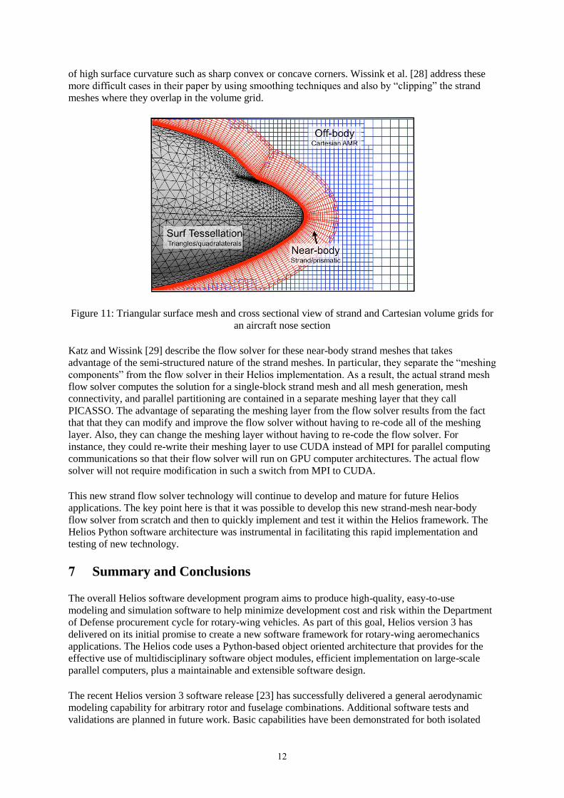
Figure 11 shows a triangular surface mesh and a cross sectional view of the strand and Cartesian
volume grids for a typical aircraft nose section. The off-body grids in Helios automatically refine in
order to match the mesh spacing at the outer boundary of the near-body strand mesh. Of course, the
example shown in Figure 11 is fairly easy to grid with a strand mesh since it doesn’t have any regions
12
of high surface curvature such as sharp convex or concave corners. Wissink et al. [28] address these
more difficult cases in their paper by using smoothing techniques and also by “clipping” the strand
meshes where they overlap in the volume grid.
Figure 11: Triangular surface mesh and cross sectional view of strand and Cartesian volume grids for
an aircraft nose section
Katz and Wissink [29] describe the flow solver for these near-body strand meshes that takes
advantage of the semi-structured nature of the strand meshes. In particular, they separate the “meshing
components” from the flow solver in their Helios implementation. As a result, the actual strand mesh
flow solver computes the solution for a single-block strand mesh and all mesh generation, mesh
connectivity, and parallel partitioning are contained in a separate meshing layer that they call
PICASSO. The advantage of separating the meshing layer from the flow solver results from the fact
that that they can modify and improve the flow solver without having to re-code all of the meshing
layer. Also, they can change the meshing layer without having to re-code the flow solver. For
instance, they could re-write their meshing layer to use CUDA instead of MPI for parallel computing
communications so that their flow solver will run on GPU computer architectures. The actual flow
solver will not require modification in such a switch from MPI to CUDA.
This new strand flow solver technology will continue to develop and mature for future Helios
applications. The key point here is that it was possible to develop this new strand-mesh near-body
flow solver from scratch and then to quickly implement and test it within the Helios framework. The
Helios Python software architecture was instrumental in facilitating this rapid implementation and
testing of new technology.
7 Summary and Conclusions
The overall Helios software development program aims to produce high-quality, easy-to-use
modeling and simulation software to help minimize development cost and risk within the Department
of Defense procurement cycle for rotary-wing vehicles. As part of this goal, Helios version 3 has
delivered on its initial promise to create a new software framework for rotary-wing aeromechanics
applications. The Helios code uses a Python-based object oriented architecture that provides for the
effective use of multidisciplinary software object modules, efficient implementation on large-scale
parallel computers, plus a maintainable and extensible software design.
The recent Helios version 3 software release [23] has successfully delivered a general aerodynamic
modeling capability for arbitrary rotor and fuselage combinations. Additional software tests and
validations are planned in future work. Basic capabilities have been demonstrated for both isolated
13
rotors and rotor/fuselage combinations with multidisciplinary coupling between fluid and structural
dynamics.
The success of the Helios software development effort is heavily dependent on the use of its
lightweight Python infrastructure that connects individual component software modules using well-
defined interfaces for each component software module. This paper points to several examples of
how this approach has facilitated the rapid addition of new component software modules within
Helios, the rapid addition of alternate legacy software components within Helios, and the rapid
implementation and testing of new technology within Helios. Hopefully, this flexible software design
will continue to facilitate collaborations with others, the leveraging of existing technology, and the
rapid implementation and testing of new technology within Helios.
References [1] Power, G. D., and Calahan, J., “A Flexible System for the Analysis of Bodies in Relative
Motion,” AIAA 2005-5120, 35th AIAA Fluid Dynamics Conference and Exhibit, Toronto
Ontario Canada, June 2005.
[2] Kingsley, G., Siegel, J., Harrand, V., Lawrence, C., Luker, J., “Development of a Multi-
Disciplinary Computing Environment (MDICE),” AIAA-98-4738, AIAA/USAF/NASA/ISSMO
Symposium on Multidisciplinary Analysis and Optimization, St. Louis MO, Sept 1998.
[3] Edwards, H. C., and Stewart, J., “SIERRA, a software environment for developing complex
multiphysics applications,” Computational Fluid and Solid Mechanics: Proceedings of the First
MIT Conference, K.J. Bathe (Ed.), Cambridge, MA, 2001, Elsevier, Oxford, UK, 2001, pp.
1147-1150.
[4] Hensaw, W. H., “Overture: An Object-Oriented Framework for Overlapping Grid Applications,”
AIAA-2002-3189, 32nd
AIAA Fluid Dynamics Conference and Exhibit, St. Louis MO, June 2002.
[5] Sitaraman, J., Floros, M., Wissink, A. and Potsdam, M.,“Parallel Unsteady Overset Mesh
Methodology for a Multi-Solver Paradigm with Adaptive Cartesian Grids”, AIAA Applied
Aerodynamics Meeting and Exhibit, AIAA-2008-7177, Honolulu, Hawaii, August, 2008.
[6] Wissink, A., Sitaraman, J., Mavriplis, D., Pulliam, T., and Sankaran, V., “A Python-Based
Infrastructure for Overset CFD with Adaptive Cartesian Grids,” 46th AIAA Aerospace Sciences
Meeting, AIAA-2008-0927, Reno, Nevada, January 2008.
[7] Sitaraman, J., Katz, A., Jayaraman, B., Wissink, A., and Sankaran, V., “Evaluation of a Multi-
Solver Paradigm for CFD using Overset Unstructured and Structured Adaptive Cartesian Grids,”
AIAA Aerospace Sciences Meeting, AIAA-2008-0660, Reno, Nevada, 2008.
[8] Oliphant, T., “Python for Scientific Computing,” Computers in Science and Engineering,
May/June, 2007.
[9] Alonso, J., LeGresley, P., van der Weide, E., Martins, J., and Reuther, J., “pyMDO: A
Framework for High-Fidelity Multi-Disciplinary Optimization,” AIAA-2004-4480, 10th
AIAA/ISSMO Multidisciplinary Analysis and Optimization Conference, Albany NY, Aug 2004.
[10] Schluter, J. U., X. Wu, S. Kim, J. J. Alonso, and H. Pitsch, “Integrated Simulations of a
compressor/combustor assembly of a gas turbine engine,” ASME paper No. GT2005-68204,
ASME Turbo Expo 2005, Reno NV, June 2005.
[11] Gopalan, G., J. Sitaraman, J. D. Baeder and F. H. Schmitz, “Aerodynamic and Aeroacoustic
Prediction Methodologies with Application to the HART II Model Rotor,” Presented at the 62nd
American Helicopter Society Annual Forum, Phoenix AZ, May 2006.
[12] Mavriplis, D. J., and Venkatakrishnan, V., “A Unified Multigrid Solver for the Navier-Stokes
Equations on Mixed Element-Meshes,” International Journal for Computational Fluid Dynamics,
Vol. 8, 1997, pp. 247-263.
14
[13] Mavriplis, D. J., and Pirzadeh, S., “Large-Scale Parallel Unstructured Mesh Computations for 3D
High-Lift Analysis,” AIAA Journal of Aircraft, Vol. 36, No. 6, 1999, pp. 987-998.
[14] Spalart, P. R., and S. R. Allmaras, S., “A One-equation Turbulence Model for Aerodynamic
Flows,” La Recherche Aerospatiale, Vol. 1, 1994, pp. 5–21.
[15] Wilcox, D. C., “Re-assessment of the Scale-determining Equation for Advanced Turbulence
Models”, AIAA Journal, Vol. 26, 1988, pp. 1414–1421.
[16] Stewart, J. R., and Edwards, H., “The SIERRA framework for developing advanced parallel
mechanics applications,” in: Large-Scale PDE-Constrained Optimization, LL. Biegler, O.
Ghattas, M. Heinkenschloss, B. van Bloemen Waanders (Eds.),Vol. 30, Springer, Berlin, July
2003.
[17] Henshaw, W. H., and Schwendeman, D., “Moving Overlapping Grids with Adaptive Mesh
Refinement for High-Speed Reactive and Non-reactive Flow,” J. Comp. Phys., 216, Issue 2, Aug
2006, pp. 744–779.
[18] Hornung, R. D., and Kohn, S., “Managing Application Complexity in the SAMRAI object-
oriented framework,” Concurrency and Computation: Practise and Experience, Vol. 14, 2002, pp.
347-368.
[19] Hornung, R. D., Wissink, A., and Kohn, S., “Managing Complex Data and Geometry in Parallel
Structured AMR Applications,” Engineering with Computers, Vol. 22, No.3-4, Dec. 2006, pp.
181-195. Also see http:// www.llnl.gov/casc/samrai.
[20] Pulliam, T. H., and Steger, J. L., “Recent Improvements in Efficiency, Accuracy, and
Convergence for Implicit Approximate Factorization Algorithms,” Paper 1985-0360, AIAA
Aerospace Sciences Meeting, 23rd, Reno, NV; United States; 14-17 Jan.
[21] Sitaraman, J., Floros, M., Wissink, A. and Potsdam, M.,“Parallel Unsteady Overset Mesh
Methodology for a Multi-Solver Paradigm with Adaptive Cartesian Grids”, AIAA Applied
Aerodynamics Meeting and Exhibit, AIAA-2008-7177, Honolulu, Hawaii, August, 2008.
[22] Saberi, H., Khoshlahjeh, M., Ormiston, R., and Rutkowski, M. J., “Overview of RCAS and
Application to Advanced Rotorcraft Problems,” 4th AHS Decennial Specialists Conference on
Aeromechanics, San Francisco, CA, January 21-23, 2004.
[23] Wissink, A., Jayaraman, B., Datta, A., Sitaraman, J., Potsdam, M., Kamkar, S., Mavriplis, D.,
Yang, Z., Jain, R., Lim, J., Strawn, R., “Capability Enhancements in Version 3 of the Helios
High-Fidelity Rotorcraft Simulation Code,” AIAA-2012-713, 50th AIAA Aerospace Sciences
Meeting, Nashville TN, Jan 9-12 2012.
[24] Yu, Y. H., Tung, C., van der Wall, B. G., Pausder, H., Burley, C., Brooks, T., Beaumier, P.,
Delrieux, Y., Mercker, E., and Pengel, K., “The HART-II Test: Rotor Wakes and Aeroacoustics
with Higher- Harmonic Pitch Control (HHC) Inputs-The Joint German/French/Dutch/US
Project,” American Helicopter Society 58th Annual Forum Proceedings, Montreal, Canada, June
11-13, 2002.
[25] Lim, J., Wissink, A., Jayaraman, B., and Dimanlig, A., “Helios Adaptive Mesh Refinement for
HART II Rotor Wake Simulations,” Presented at the American Helicopter Society Annual Forum
68, Aerodynamic Session, May 1-3, 2012, Fort Worth, Texas.
[26] “ParaView Homepage”, Retrieved from http://www.paraview.org
[27] Nichols, R.H., Tramel, R.W., and Buning, P.G., “Solver and Turbulence Model Upgrades to
OVERFLOW 2 for Unsteady and High-Speed Applications,” AIAA 2006-2824, June 2006.
[28] Wissink, A., Katz, A, and Sitaraman, J., “PICASSO: A Meshing Infrastructure for Strand-
Cartesian CFD Solvers,” AIAA-2012-2916 30th AIAA Applied Aerodynamics Conference, New
Orleans, Louisiana, June 25-28, 2012.

15
[29] Katz, A., and Wissink, A., “Efficient Solution Methods for Strand Grid Applications,”AIAA-
2012-2779, 30th AIAA Applied Aerodynamics Conference, New Orleans, Louisiana, June 25-28,
2012.