software implementation of pulse width modulation...
TRANSCRIPT

Software Implementation of Pulse Width
Modulation (PWM).A reference design using the
Spartan-3E Starter Kit
Ken ChapmanXilinx Ltd24th May 2006
Rev.1

PicoBlaze PWM for the Spartan-3E Starter Kit 2
Limited Warranty and Disclaimer. These designs are provided to you “as is”. Xilinx and its licensors make and you receive no warranties or conditions, express, implied, statutory or otherwise, and Xilinx specifically disclaims any implied warranties of merchantability, non-infringement, or fitness for a particular purpose. Xilinx does not warrant that the functions contained in these designs will meet your requirements, or that the operation of these designs will be uninterrupted or error free, or that defects in the Designs will be corrected. Furthermore, Xilinx does not warrant or make any representations regarding use or the results of the use of the designs in terms of correctness, accuracy, reliability, or otherwise.
Limitation of Liability. In no event will Xilinx or its licensors be liable for any loss of data, lost profits, cost or procurement of substitute goods or services, or for any special, incidental, consequential, or indirect damages arising from the use or operation of the designs or accompanying documentation, however caused and on any theory of liability. This limitation will apply even if Xilinx has been advised of the possibility of such damage. This limitation shall apply not-withstanding the failure of the essential purpose of any limited remedies herein.
This design module is not supported by general Xilinx Technical support as an official Xilinx Product.Please refer any issues initially to the provider of the module.
Any problems or items felt of value in the continued improvement of KCPSM3 or this reference design would be gratefully received by the author.
Ken ChapmanSenior Staff Engineer – Spartan Applications Specialistemail: [email protected]
Limitations
The author would also be pleased to hear from anyone using KCPSM3 or the UART macros with information about your application and how these macros have been useful.

PicoBlaze PWM for the Spartan-3E Starter Kit 3
Design OverviewThis design allows you to experiment with Pulse Width Modulation (PWM) implemented by a PicoBlaze processor. As supplied , the design will allow you to control 12 PWM channels; 8 channels control the intensity of the 8 LEDs on the board and the remaining 4 channel are provided on connector ‘J4’ which you can observe should you have access to an oscilloscope. You may also like to experiment with simple resistor-capacitor (RC) smoothing circuits connected to the header pins to create additional digital to analogue (D/A) converters or experiment with controlling motors via drive transistors.
The PWM implemented has a pulse repetition frequency (PRF) of 1KHz and an 8-bit resolution (256 steps). The duty cycle for Each LED or ‘J4’ output can be set independently using simple commands entered at a simple terminal program on your PC (HyperTerminal is ideal).
The PicoBlaze processor and UART macros occupy less than 5% of the XC3S500E device. It is hoped that the design may be of interest to anyone interested in PWM and will help you to realise that PicoBlaze is small enough to include in a design even if dedicated to a task such as PWM.
HyperTerminal(or similar)
RS232Serial Communication
9600 baud8-bitsNo ParityNo flow control
8 LEDs
4 header pins (J4)
PRF=1KHz(PRI=1ms)
8-bit resolution(256 steps of 3.9µs)
Duty=17/256
Duty=188/256
Duty=239/256
Duty=34/256
IO9
IO10
IO11
IO12
LD0
LD1
LD2
LD3
LD4
LD5
LD6
LD7Intensity control
PicoBlaze PWM for the Spartan-3E Starter Kit 4
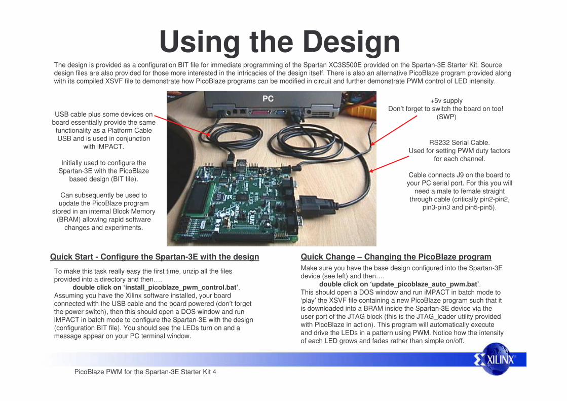
Using the DesignThe design is provided as a configuration BIT file for immediate programming of the Spartan XC3S500E provided on the Spartan-3E Starter Kit. Source design files are also provided for those more interested in the intricacies of the design itself. There is also an alternative PicoBlaze program provided along with its compiled XSVF file to demonstrate how PicoBlaze programs can be modified in circuit and further demonstrate PWM control of LED intensity.
USB cable plus some devices on board essentially provide the same functionality as a Platform Cable USB and is used in conjunction
with iMPACT.
Initially used to configure the Spartan-3E with the PicoBlaze
based design (BIT file).
Can subsequently be used to update the PicoBlaze program
stored in an internal Block Memory (BRAM) allowing rapid software
changes and experiments.
RS232 Serial Cable. Used for setting PWM duty factors
for each channel.
Cable connects J9 on the board to your PC serial port. For this you will
need a male to female straight through cable (critically pin2-pin2,
pin3-pin3 and pin5-pin5).
+5v supplyDon’t forget to switch the board on too!
(SWP)
PC
To make this task really easy the first time, unzip all the files provided into a directory and then….
double click on ‘install_picoblaze_pwm_control.bat’. Assuming you have the Xilinx software installed, your board connected with the USB cable and the board powered (don’t forget the power switch), then this should open a DOS window and run iMPACT in batch mode to configure the Spartan-3E with the design (configuration BIT file). You should see the LEDs turn on and a message appear on your PC terminal window.
Quick Start - Configure the Spartan-3E with the design Quick Change – Changing the PicoBlaze programMake sure you have the base design configured into the Spartan-3E device (see left) and then….
double click on ‘update_picoblaze_auto_pwm.bat’. This should open a DOS window and run iMPACT in batch mode to ‘play’ the XSVF file containing a new PicoBlaze program such that it is downloaded into a BRAM inside the Spartan-3E device via the user port of the JTAG block (this is the JTAG_loader utility provided with PicoBlaze in action). This program will automatically execute and drive the LEDs in a pattern using PWM. Notice how the intensity of each LED grows and fades rather than simple on/off.
PicoBlaze PWM for the Spartan-3E Starter Kit 5
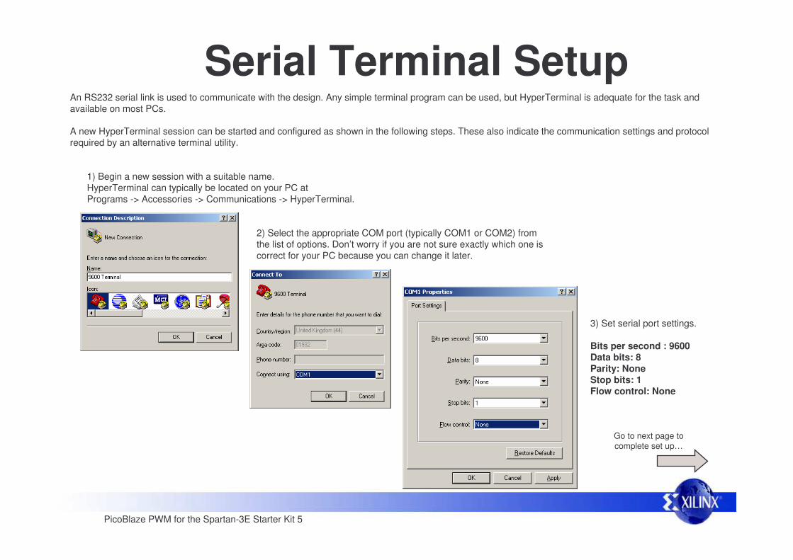
Serial Terminal Setup An RS232 serial link is used to communicate with the design. Any simple terminal program can be used, but HyperTerminal is adequate for the task and available on most PCs.
A new HyperTerminal session can be started and configured as shown in the following steps. These also indicate the communication settings and protocol required by an alternative terminal utility.
1) Begin a new session with a suitable name.HyperTerminal can typically be located on your PC at Programs -> Accessories -> Communications -> HyperTerminal.
2) Select the appropriate COM port (typically COM1 or COM2) fromthe list of options. Don’t worry if you are not sure exactly which one is correct for your PC because you can change it later.
3) Set serial port settings.
Bits per second : 9600Data bits: 8Parity: NoneStop bits: 1Flow control: None
Go to next page to complete set up…
PicoBlaze PWM for the Spartan-3E Starter Kit 6
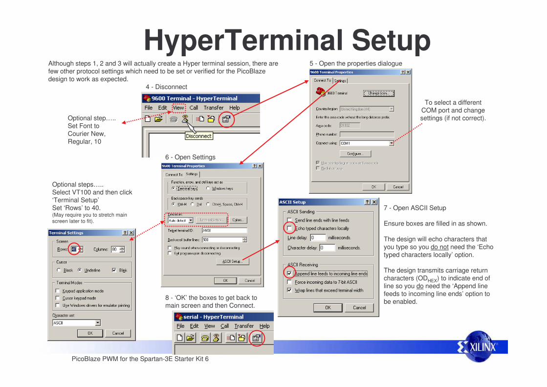
HyperTerminal Setup 4 - Disconnect
5 - Open the properties dialogue
To select a different COM port and change settings (if not correct).
6 - Open Settings
7 - Open ASCII Setup
Ensure boxes are filled in as shown.
The design will echo characters that you type so you do not need the ‘Echo typed characters locally’ option.
The design transmits carriage return characters (ODHEX) to indicate end of line so you do need the ‘Append line feeds to incoming line ends’ option to be enabled.
Although steps 1, 2 and 3 will actually create a Hyper terminal session, there are few other protocol settings which need to be set or verified for the PicoBlaze design to work as expected.
8 - ‘OK’ the boxes to get back to main screen and then Connect.
Optional steps…..Select VT100 and then click ‘Terminal Setup’Set ‘Rows’ to 40.(May require you to stretch main screen later to fit).
Optional step…..Set Font to Courier New,Regular, 10

PicoBlaze PWM for the Spartan-3E Starter Kit 7
PWM Control
Welcome message
Enter commands in upper or lower case
Valid commands acknowledged with ‘OK’
Any mistakes in command entry results in ‘Error’
Type commands to the prompt.Backspace key is supported to allow simple editing.Single space between command and hex value.End command entry with Carriage Return.
Commands to control LEDs (PWM channels 0 to 7)….
LDn hh
Where'n' is an LED number in the range 0 to 7.'hh' is a 2 digit hex value to specify the PWM duty factor
(range 00 to FF).
Commands to set simple outputs on connector J4….
IOk hh
Where‘k' is an IO number in the range 9 to 12.'hh' is a 2 digit hex value to specify the PWM duty factor
(range 00 to FF).
The duty cycle for each PWM channel can be set independently using some simple commands typed at the terminal on your PC. Commands should be formatted exactly as described for this simple program to understand them.
Some command examples are shown in this HyperTerminal session.
Note that PicoBlaze is able to perform the interpretation of thecommands including the simple line editor function whilst maintaining accurate generation of the 12 PWM channels.
Exercise – Determine the smallest duty cycle value which makes an LED visible in daylight and in the dark. Estimate the duty cycle values required to increase the intensity of an LED in what appears to be a linear fashion to the human eye.

PicoBlaze PWM for the Spartan-3E Starter Kit 8
Default PWM SettingsAlthough practical implementations of PWM generators would tend to initialise to the off state (duty cycle of zero), this design is provided to give a mixture of outputs which you can observe and then modify via the terminal commands. The initial duty cycles are as shown below but can be easily changed in the PicoBlaze program if the design is used in a real application.
The LEDs should all appear to be on to some degree with the intention that LD0 should appear to be very dim and LD7 very bright. This demonstrates how PWM can be used to control the intensity of an LED and also indicates how PWM can be used in general to achieve intermediate drive strengths by an averaging process of fully ‘on’ or ‘off’ states.
Duty17/256
Duty188/256
Duty239/256
Duty34/256
This oscilloscope plot shows the default output from the 4 simple IO pins on connector J4. It shows that the PRF is approximately 1KHz (see page 13) and four different duty cycle settings.
PRF997Hz
Exercise – Connect a simple R-C circuit to IO9 and measure the voltage level realised for different duty cycle settings. Your RC time constant should be large in comparison to the PRF period if you intend to have a smooth output level (R × C » 1ms). Think in terms of a smoothing capacitor after a rectifier and consider how a load will also have an effect on ripple. GND
IO9
VDC
R
C
PicoBlaze PWM for the Spartan-3E Starter Kit 9
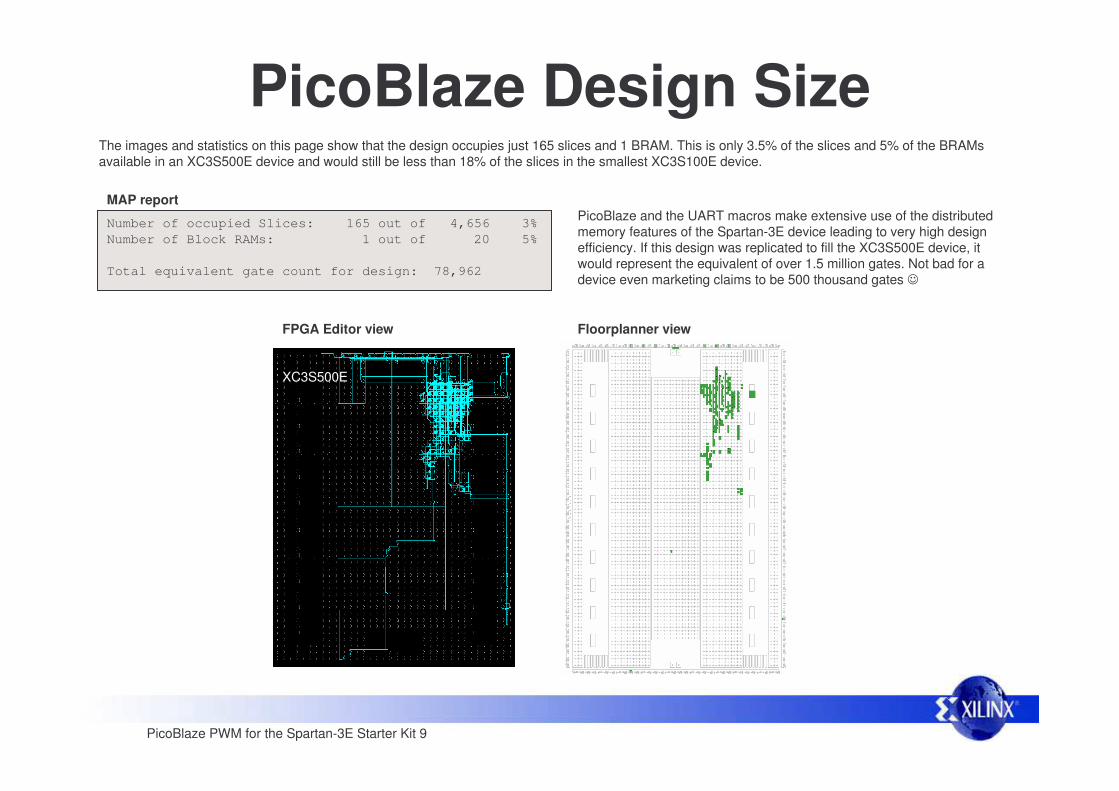
PicoBlaze Design SizeThe images and statistics on this page show that the design occupies just 165 slices and 1 BRAM. This is only 3.5% of the slices and 5% of the BRAMs available in an XC3S500E device and would still be less than 18% of the slices in the smallest XC3S100E device.
Number of occupied Slices: 165 out of 4,656 3%Number of Block RAMs: 1 out of 20 5%
Total equivalent gate count for design: 78,962
PicoBlaze and the UART macros make extensive use of the distributed memory features of the Spartan-3E device leading to very high design efficiency. If this design was replicated to fill the XC3S500E device, it would represent the equivalent of over 1.5 million gates. Not bad for a device even marketing claims to be 500 thousand gates �
MAP report
FPGA Editor view Floorplanner view
XC3S500E
PicoBlaze PWM for the Spartan-3E Starter Kit 10
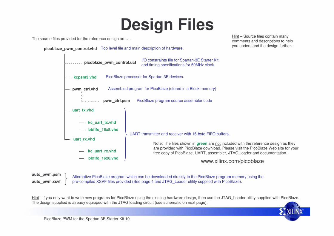
Design FilesThe source files provided for the reference design are…..
picoblaze_pwm_control.vhd Top level file and main description of hardware.
PicoBlaze program source assembler code
kcpsm3.vhd PicoBlaze processor for Spartan-3E devices.
pwm_ctrl.vhd
I/O constraints file for Spartan-3E Starter Kit and timing specifications for 50MHz clock.
pwm_ctrl.psm
Assembled program for PicoBlaze (stored in a Block memory)
Note: The files shown in green are not included with the reference design as they are provided with PicoBlaze download. Please visit the PicoBlaze Web site for your free copy of PicoBlaze, UART, assembler, JTAG_loader and documentation.
www.xilinx.com/picoblaze
Hint - If you only want to write new programs for PicoBlaze using the existing hardware design, then use the JTAG_Loader utility supplied with PicoBlaze. The design supplied is already equipped with the JTAG loading circuit (see schematic on next page).
auto_pwm.xsvfAlternative PicoBlaze program which can be downloaded directly to the PicoBlaze program memory using the pre-compiled XSVF files provided (See page 4 and JTAG_Loader utility supplied with PicoBlaze).
auto_pwm.psm
bbfifo_16x8.vhd
kc_uart_tx.vhd
uart_rx.vhd
bbfifo_16x8.vhd
kc_uart_rx.vhd
uart_tx.vhd
UART transmitter and receiver with 16-byte FIFO buffers.
picoblaze_pwm_control.ucf
Hint – Source files contain many comments and descriptions to help you understand the design further.
PicoBlaze PWM for the Spartan-3E Starter Kit 11
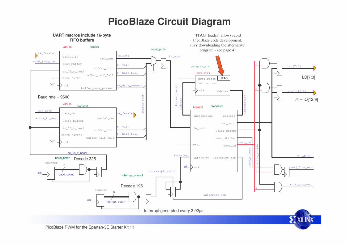
PicoBlaze Circuit Diagram
buffer_full
uart_rx receive
serial_in
clk
data_out
reset_buffer
buffer_data_present
en_16_x_baud
read_buffer
buffer_half_fullrx_half_full
rx_full
rx_data_present
read_from_uart
rx_datarx_female
buffer_full
uart_txtransmit
data_in
clk
serial_out
reset_buffer
en_16_x_baud
write_buffer
buffer_half_full
tx_half_full
tx_full
out_porttx_female
write_to_uart
9
baud_count
Decode 325
clk
en_16_x_baud
UART macros include 16-byte FIFO buffers
baud_timer
counter
status_port
interrupt_controlinterrupt_event
‘JTAG_loader’ allows rapid PicoBlaze code development.
(Try downloading the alternative program - see page 4)
port_id
kcpsm3 processor
instruction
write_strobe
clk
out_port
read_strobe
address
reset
interrupt_ackinterrupt
in_port
instruction
address
pwm_ctrl
program_rom
instruction
addressclk
port_id
out_port
read_strobe
interrupt_ack
interrupt
in_port
JTAGproc_reset
clk
kcpsm3_reset
0
read_from_uart
write_to_uart
input_ports
0
5
7
write_strobe
led[7:0]
6simple[3:0]
8
interrupt_countclk
counterDecode 195
Interrupt generated every 3.92µs
Baud rate = 9600 J4 – IO[12:9]
LD[7:0]

PicoBlaze PWM for the Spartan-3E Starter Kit 12
This design deliberately explores the generation of PWM using software executed by PicoBlaze rather than using PicoBlaze in conjunction with PWM hardware peripherals (which will be covered in a subsequent reference design). This means that the dynamics of the PWM are totally flexible by software definition but also means that there are some limits as to what can be achieved.
PWM and the Limits of Software
The two key parameters of PWM are the Pulse Repetition Frequency (PRF) and the resolution (number of steps) by which the duty cycle of each pulse can be set. The design supplied has a PRF or 1KHz and a resolution of 8-bits (256 steps). As such, each step must be resolved at intervals of 3.92µs.
PRF=1KHz(1/1000=1ms) 8-bit resolution = 256 steps
1ms/256 = 3.90625µs)
Exercise – Determine the maximum PRF which can be achieved for a single channel PWM controller if the resolution is to be 100 steps (8-bit values expressing percent of cycle 0% to 100%). Allow 25% overhead for PicoBlaze to perform higher level tasks using the same 50MHz clock source.
Hint – Even if the limits of software execution are reached, it is quite possible to use more than one PicoBlaze processor in any Spartan device. PicoBlaze used in this way can provide ‘intelligent’ PWM peripherals to another PicoBlaze or MicroBlaze processor acting as the main system controller.
PicoBlaze is a highly predictable processor requiring 2 clock cycles to execute every instruction. Although PicoBlaze can be clocked faster even in the slowest speed grade of Spartan device, this reference makes direct use of the 50MHz oscillator on the board. As such, PicoBlaze is able to execute 25 million instructions per second (MIPS) or one instruction every 40ns. Although this is relatively fast for a small 8-bit microcontroller, it means that it can only execute 97 instructions within the 3.90625µs step interval to support the PRF and resolution described above. However, 97 instructions are adequate to drive the PWM signals for all 12 channels and still have ~50% of the processor bandwidth available for the higher level control tasks (dealing with the UART and processing text commands in this case). It should be noted that in this design the PWM generation is continuous. It is quite common for software implementations of PWM with microcontrollers to only support bursts of pulses in order to have time to perform other processing tasks. Such a compromise should never be required when using an FPGA given the high performance of PicoBlaze and the ability to include hardware peripherals if required.
Increasing PRF and/or increasing the duty resolution will reduce the number of instructions which can be executed during each step. In the limit, there will only be enough instructions available to describe the PWM itself and PicoBlaze will have no capacity to actually do anything else. Higher clock rates can be considered, but really this is when a hardware peripheral implemented in the FPGA fabric will make more sense.
PicoBlaze PWM for the Spartan-3E Starter Kit 13
Store PWM duty factor in SPM
Interpret command and deduce channel and PWM duty factor setting if valid
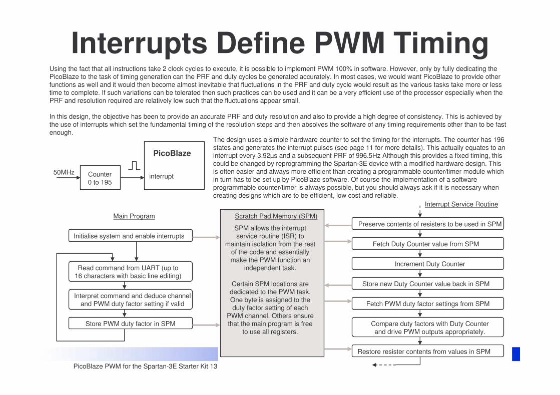
Using the fact that all instructions take 2 clock cycles to execute, it is possible to implement PWM 100% in software. However, only by fully dedicating the PicoBlaze to the task of timing generation can the PRF and duty cycles be generated accurately. In most cases, we would want PicoBlaze to provide other functions as well and it would then become almost inevitable that fluctuations in the PRF and duty cycle would result as the various tasks take more or less time to complete. If such variations can be tolerated then such practices can be used and it can be a very efficient use of the processor especially when the PRF and resolution required are relatively low such that the fluctuations appear small.
In this design, the objective has been to provide an accurate PRF and duty resolution and also to provide a high degree of consistency. This is achieved by the use of interrupts which set the fundamental timing of the resolution steps and then absolves the software of any timing requirements other than to be fast enough.
Interrupts Define PWM Timing
PicoBlaze
interruptCounter0 to 195
50MHz
The design uses a simple hardware counter to set the timing for the interrupts. The counter has 196 states and generates the interrupt pulses (see page 11 for more details). This actually equates to an interrupt every 3.92µs and a subsequent PRF of 996.5Hz Although this provides a fixed timing, this could be changed by reprogramming the Spartan-3E device with a modified hardware design. This is often easier and always more efficient than creating a programmable counter/timer module which in turn has to be set up by PicoBlaze software. Of course the implementation of a software programmable counter/timer is always possible, but you should always ask if it is necessary when creating designs which are to be efficient, low cost and reliable.
Interrupt Service Routine
Fetch Duty Counter value from SPM
Read command from UART (up to 16 characters with basic line editing)
Initialise system and enable interrupts
Preserve contents of resisters to be used in SPM
Restore resister contents from values in SPM
Fetch PWM duty factor settings from SPM
Increment Duty Counter
Store new Duty Counter value back in SPM
Compare duty factors with Duty Counter and drive PWM outputs appropriately.
Scratch Pad Memory (SPM)
SPM allows the interrupt service routine (ISR) to
maintain isolation from the rest of the code and essentially make the PWM function an
independent task.
Certain SPM locations are dedicated to the PWM task. One byte is assigned to the duty factor setting of each
PWM channel. Others ensure that the main program is free
to use all registers.
Main Program
PicoBlaze PWM for the Spartan-3E Starter Kit 14
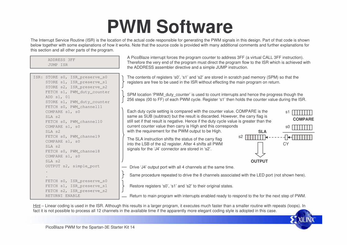
The Interrupt Service Routine (ISR) is the location of the actual code responsible for generating the PWM signals in this design. Part of that code is shown below together with some explanations of how it works. Note that the source code is provided with many additional comments and further explanations for this section and all other parts of the program.
PWM SoftwareADDRESS 3FFJUMP ISR
A PicoBlaze interrupt forces the program counter to address 3FF (a virtual CALL 3FF instruction). Therefore the very end of the program must direct the program flow to the ISR which is achieved with the ADDRESS assembler directive and a simple JUMP instruction.
ISR: STORE s0, ISR_preserve_s0 STORE s1, ISR_preserve_s1STORE s2, ISR_preserve_s2FETCH s1, PWM_duty_counterADD s1, 01STORE s1, PWM_duty_counterFETCH s0, PWM_channel11 COMPARE s1, s0 SLA s2 FETCH s0, PWM_channel10 COMPARE s1, s0 SLA s2 FETCH s0, PWM_channel9 COMPARE s1, s0 SLA s2 FETCH s0, PWM_channel8 COMPARE s1, s0 SLA s2 OUTPUT s2, simple_port..FETCH s0, ISR_preserve_s0 FETCH s1, ISR_preserve_s1FETCH s2, ISR_preserve_s2RETURNI ENABLE
The contents of registers ‘s0’, ‘s1’ and ‘s2’ are stored in scratch pad memory (SPM) so that the registers are free to be used in the ISR without effecting the main program on return.
Restore registers ‘s0’, ‘s1’ and ‘s2’ to their original states.
Return to main program with interrupts enabled ready to respond to the for the next step of PWM.
SPM location ‘PWM_duty_counter’ is used to count interrupts and hence the progress though the 256 steps (00 to FF) of each PWM cycle. Register ‘s1’ then holds the counter value during the ISR.
s1
s0
COMPARE
CY
s2SLA
Drive ‘J4’ output port with all 4 channels at the same time. OUTPUT
Same procedure repeated to drive the 8 channels associated with the LED port (not shown here).
Each duty cycle setting is compared with the counter value. COMPARE is the same as SUB (subtract) but the result is discarded. However, the carry flag is still set if that result is negative. Hence if the duty cycle value is greater than the current counter value then carry is High and this corresponds with the requirement for the PWM output to be High.
The SLA instruction shifts the status of the carry flag into the LSB of the s2 register. After 4 shifts all PWM signals for the ‘J4’ connector are stored in ‘s2’.
Hint – Linear coding is used in the ISR. Although this results in a larger program, it executes much faster than a smaller routine with repeats (loops). In fact it is not possible to process all 12 channels in the available time if the apparently more elegant coding style is adopted in this case.
PicoBlaze PWM for the Spartan-3E Starter Kit 15
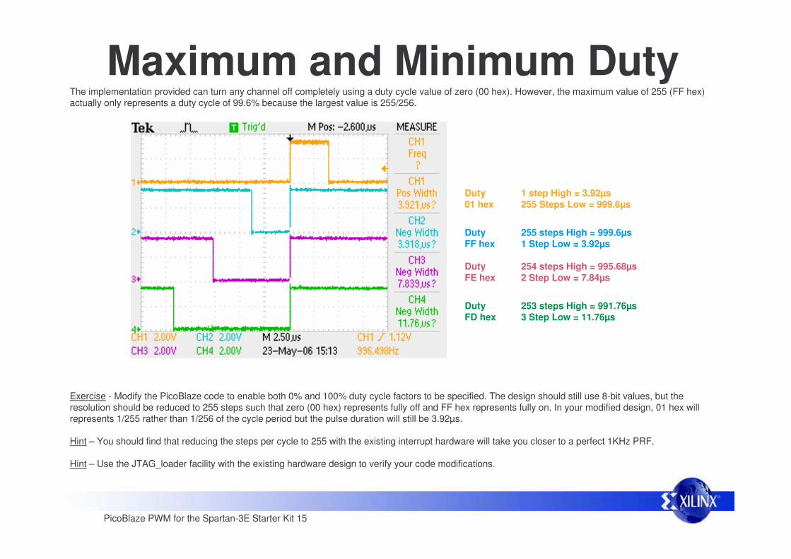
The implementation provided can turn any channel off completely using a duty cycle value of zero (00 hex). However, the maximum value of 255 (FF hex) actually only represents a duty cycle of 99.6% because the largest value is 255/256.
Maximum and Minimum Duty
Exercise - Modify the PicoBlaze code to enable both 0% and 100% duty cycle factors to be specified. The design should still use 8-bit values, but the resolution should be reduced to 255 steps such that zero (00 hex) represents fully off and FF hex represents fully on. In your modified design, 01 hex will represents 1/255 rather than 1/256 of the cycle period but the pulse duration will still be 3.92µs.
Hint – You should find that reducing the steps per cycle to 255 with the existing interrupt hardware will take you closer to a perfect 1KHz PRF.
Hint – Use the JTAG_loader facility with the existing hardware design to verify your code modifications.
Duty01 hex
DutyFF hex
DutyFE hex
DutyFD hex
1 step High = 3.92µs255 Steps Low = 999.6µs
255 steps High = 999.6µs1 Step Low = 3.92µs
254 steps High = 995.68µs2 Step Low = 7.84µs
253 steps High = 991.76µs3 Step Low = 11.76µs