software pll design using c2000 mcus single phase grid ... · important notice for ti design...
TRANSCRIPT

1SPRABT3A–July 2013–Revised July 2017Submit Documentation Feedback
Copyright © 2013–2017, Texas Instruments Incorporated
Software Phase Locked Loop Design Using C2000™ Microcontrollers forSingle Phase Grid Connected Inverter
Application ReportSPRABT3A–July 2013–Revised July 2017
Software Phase Locked Loop Design Using C2000™Microcontrollers for Single Phase Grid Connected Inverter
ManishBhardwaj
ABSTRACTGrid connected applications require an accurate estimate of the grid angle to feed power synchronously tothe grid. This is achieved using a software phase locked loop (PLL). This application report discussesdifferent challenges in the design of software phase locked loops and presents a methodology to designphase locked loops using C2000 controllers for single phase grid connection applications.
Contents1 Introduction ................................................................................................................... 12 PLL With Notch Filter........................................................................................................ 33 Orthogonal Signal Generator PLL ....................................................................................... 144 Solar Library and ControlSuite™......................................................................................... 245 References .................................................................................................................. 24
List of Figures
1 Phase Locked Loop Basic Structure ...................................................................................... 22 Single Phase PLL With Notch Filter....................................................................................... 33 Bode Diagram ................................................................................................................ 54 PLL Response to Varying Grid Conditions ............................................................................... 95 Implemented SPLL at Steady State With Phase Jump and Scope Captures...................................... 136 OSG Based Single Phase PLL ........................................................................................... 147 Second Order Generalized Integrator for Orthogonal Signal Generation........................................... 148 Extraction of the Fifth Harmonic Using the SOGI ...................................................................... 159 PLL Response to Varying Grid Conditions ............................................................................. 1810 Transient Response........................................................................................................ 23
TrademarksC2000, ControlSuite are trademarks of Texas Instruments.MATLAB is a registered trademark of The MathWorks, Inc.All other trademarks are the property of their respective owners.
1 IntroductionThe phase angle of the utility is a critical piece of information for the operation of power devices feedingpower into the grid like PV inverters. A phase locked loop is a closed loop system in which an internaloscillator is controlled to keep the time and phase of an external periodical signal using a feedback loop.The PLL is simply a servo system that controls the phase of its output signal such that the phase errorbetween the output phase and the reference phase is minimum. The quality of the lock directly affects theperformance of the control loop in grid tied applications. As line notching, voltage unbalance, line dips,phase loss and frequency variations are common conditions faced by equipment interfacing with electricutility, the PLL needs to be able to reject these sources of error and maintain a clean phase lock to thegrid voltage.

2( )( ) 1 ( )
( ) ( ) 2
V s s sdE s H so o ks s LF s pin s k spTi
q= = - = =
++ +
( )( ) ( )
( )( ) ( ) 2
kpv k sgrid p
s TLF sout iH so ks s LF s pin s v k s vgrid p gridTi
q
q
+
= = =+
+ +
( )
2
vgrid grid PLLerr
q q-=
sin(( ) ( ))2
K vd gridv w w td grid PLL grid PLLq q= - + -
[sin(( ) ( )) sin(( ) ( ))]2
K vd gridv w w t w w td grid PLL grid PLL grid PLL grid PLLq q q q= - + - + + + +
' cos( ) cos( )v w tout PLL PLLq q= = +
sin( ) sin( )v v v w tgrid in grid grid gridq q= = +
Measure Vgrid
oω
)sin( ingridvv θ= ∫+ ip kk
LPF
Ko +
outω1/s
outθ
cos
Sin
VCO
Kde Vd
PD
V’
Introduction www.ti.com
2 SPRABT3A–July 2013–Revised July 2017Submit Documentation Feedback
Copyright © 2013–2017, Texas Instruments Incorporated
Software Phase Locked Loop Design Using C2000™ Microcontrollers forSingle Phase Grid Connected Inverter
A functional diagram of a PLL is shown in Figure 1, which consists of a phase detect (PD), a loop filter(LPF), and a voltage controlled oscillator (VCO).
Figure 1. Phase Locked Loop Basic Structure
The measured grid voltage can be written in terms the grid frequency (wgrid) as follows:(1)
Now, assuming VCO is generating sine waves close to the grid sinusoid, VCO output can be written as,
(2)
The purpose of the phase detect block is to compare the input sine with the locked sine from the VCO andto generate an error signal proportional to the angle error. For this, the phase detect block multiplies theVCO output and the measured input value to get:
(3)
From Equation 3, it is clear that the output of PD block has information of the locking error. However, thelocking error information available from the PD is not linear, and has a component which is varying attwice the grid frequency. To use this locking error information to lock the PLL angle, twice the gridfrequency component must be removed.
For now, ignoring the twice of grid frequency component, the lock error is given as:
(4)
For steady state operation, the wgrid - wPLL term can be ingored, for small values of theta sin(θ) ~ θ. Hence,a linearized error is given as:
(5)
This error is the input to loop filter, which is nothing but a PI controller, that is used to reduce the lockingerror at steady state to zero. The small signal analysis is done using network theory, where the feedbackloop is broken to get the open loop transfer equation and then the closed-loop transfer function:
Closed Loop TF = Open Loop TF / (1+ OpenLoopTF)
Thus, for the linearized feedback the PLL transfer function can be written as follows:Closed loop Phase TF:
Closed loop error transfer function:

Measure Vgrid
oω
)sin( ingridvv θ= Kdε
∫+ ip kk
PD
dvLPF
Ko +outω
1/soutθ
cos
Sin
'v
VCO
Notch Filter
4
v T Kgrid i pz =
v Kgrid pn
Tiw =
22( )
2 22
sn nH s
s sn n
zw w
zw w
+=
+ +
www.ti.com PLL With Notch Filter
3SPRABT3A–July 2013–Revised July 2017Submit Documentation Feedback
Copyright © 2013–2017, Texas Instruments Incorporated
Software Phase Locked Loop Design Using C2000™ Microcontrollers forSingle Phase Grid Connected Inverter
Comparing the closed loop phase transfer function to a generic second order system transfer function,which is given as:
(6)
The natural frequency and the damping ration of the linearized PLL are given as:
(7)(8)
(9)
Note in the PLL, the PI serves dual purpose:• To filter out high frequency that is at twice the frequency of the carrier and grid• Control response of the PLL to step changes in the grid conditions, for example, phase leaps,
magnitude swells, and so forth.
As the loop filter has low-pass filter characteristic, it can be used to filter out the high frequencycomponent that was ignored earlier. If the carrier frequency/ frequency of the signal being locked is high,the low-pass characteristics of the PI are good enough to cancel the twice of carrier frequency component.However, for grid connected applications as the grid frequency is very low (50Hz-60Hz), the roll offprovided by the PI is not satisfactory enough and introduces a high frequency element into the loop filteroutput, which affects the performance of the PLL.
From the discussion above, it is clear that the LPF characteristic of the PI controller cannot be used toeliminate the twice to grid frequency component from the phase detect output in case of grid connectedapplications. Hence, alternative methods must be used that linearize the PD block. In this applicationreport, two PLL methods that linearize the PD output, are illustrated:• One uses a notch filter to filter out twice the grid frequency component from the PD output• The other uses an orthogonal signal generation method to use stationary reference frame PLL
technique in single phase PLL
2 PLL With Notch FilterA notch filter can be used at the output of the phase detect block, which attenuates twice the gridfrequency component very well. An adaptive notch filter can also be used to selectively notch the exactfrequency in case there are variations in the grid frequency. Section 2.1 illustrates the selection procedureof the PI coefficients, their digital implementation and mapping. The design of the adaptive notch filter isillustrated and a method to calculate the coefficients automatically, and on line is illustrated with theembedded code implementation.
Figure 2. Single Phase PLL With Notch Filter

2 22 2( ) for notch action to occur2 12 22 1
s sn nH s wherenfs sn n
z w wz z
z w w
+ += <<
+ +
2 * * 2 * *0 1
2 2
K K T K K Tp i p iB and B
+ -æ ö æ ö= = -ç ÷ ç ÷ç ÷ ç ÷
è ø è ø
2Where, and and 1n
cn d nd
ws Vw w V w
w= = = -
11 1 * ln( )
ct ts sce ce tss s
s s
- -- ¶ = - => ¶ = => =
( ) 1 sin( )ty t ce tds
w j-
= - +
2( )
2 22
nH s
s sn n
w
zw w=
+ +
2 * * 2 * * 1
2 2( )
1( ) 1
K K T K K Tp i p iz
ylf z
ynotch z z
+ -æ ö æ ö --ç ÷ ç ÷ç ÷ ç ÷è ø è ø=
--
2 1( )
1
zs
T z
-=
+
( )
( )
Kylf s iKpynotch s s
= +
1( ) 0 1*
1( ) 1
ylf z B B z
ynotch z z
-+
=
--
[ ] [ 1] * 1 [ ] * 0 [ 1] * 1ylf n ylf n A ynotch n B ynotch n B= - + + -
PLL With Notch Filter www.ti.com
4 SPRABT3A–July 2013–Revised July 2017Submit Documentation Feedback
Copyright © 2013–2017, Texas Instruments Incorporated
Software Phase Locked Loop Design Using C2000™ Microcontrollers forSingle Phase Grid Connected Inverter
As discussed in Section 1, with the addition of the notch filter, the PI tuning can be done solely based ondynamic response of the PLL. Section 2.1 illustrates digital implementation of the PI controller and theselection of the coefficients for the PI controller to be used.
2.1 Discrete Implementation of PI ControllerThe loop filter or the PI is implemented as a digital controller with Equation 10:
(10)
Using z transform, Equation 10 can be re-written as:
(11)
It is well known the PI controller in laplace transform is given by:
(12)
Using bi-linear transformation, replace , where T = Sampling Time.
(13)
Equation 11 and Equation 13 can be compared to map the proportional and integral gain of the PIcontroller into the digital domain. The next challenge is selecting an appropriate value for the proportionaland integral gain.
The step response to a general second order equation:
(14)
is given as:
(15)
ignoring the LHP zero from Equation 15. The settling time is given as the time it takes for the response tosettle between an error band, say this error is ∂, then:
(16)
(17)
Using settling time as 30 ms, and the error band as 5% and damping ratio to be 0.7, the natural frequencyis obtained to be 158.6859. Back substituting Kp =222.1603 and Ki = 25181.22.
Back substituting these values into the digital loop filter coefficients:
(18)
For 50 Khz run rate of the PLL, B0 = 223.4194 and B1 = -220.901.
2.2 Adaptive Notch Filter DesignThe notch filter used in the PLL shown in Figure 2 needs to attenuate twice the grid frequency component.Grid frequency, though stable, can have some variation, and with increasing renewable content largervariation are possible. Therefore, to precisely notch twice the grid frequency, an adaptive notch filter isused. A typical notch filter equation is ‘s‘ domain as shown in Equation 19:
(19)

sin( )sin( ) sin( ) * sin( ) cos( ) *
cos( )cos( ) cos( ) * cos( ) sin( ) *
d tt t t t t t t
dt
d tt t t t t t t
dt
+ D = + D = + D
+ D = + D = - D
( )( ) ( ) *
dy ty t t y t t
dt+ D = + D
-80
-60
-40
-20
0
20
Magnitu
de
(dB
)
101
102
103
104
-90
-45
0
45
90
Phase
(deg)
Bode Diagram
Frequency (Hz)
1 22 2 2(2 2) ( 2 1) 0 1 22 2( )2 2 2 1 2(2 2) ( 2 1)1 1 0 1 2
B B z B zz T z T Tn n nH znf
z T z T T A A z A zn n n
z w z w w
z w z w w
- -+ ++ - + - + += =
- -+ - + - + + + +
( 1)zs
T
-
=
www.ti.com PLL With Notch Filter
5SPRABT3A–July 2013–Revised July 2017Submit Documentation Feedback
Copyright © 2013–2017, Texas Instruments Incorporated
Software Phase Locked Loop Design Using C2000™ Microcontrollers forSingle Phase Grid Connected Inverter
Discretizing Equation 19 using zero order hold, , the equation is reduced to:
(20)
Equation 20 maps well into a digital two-pose two-zero structure and the coefficients for the notch filtercan be adaptively changed as the grid frequency varies by calling a routine in the background thatestimates the coefficients based on measure grid frequency.
For example, taking ζ2 = 0.00001 and ζ1 = 0.1 (ζ2 << ζ1), the response of the notch is as shown in Figure 3for 50Hz and 60Hz grid, where the coefficients are updated based on grid frequency.
Figure 3. Bode Diagram
2.3 Sine and Cosine GenerationThe PLL uses sin and cos calculation, these calculations can consume large number of cycles in a typicalmicrocontroller. To avoid this issue, the sine and cosine value is generated in this module by applying theprinciple of integration.
(21)
For sine and cosine signal, this reduces to:
(22)

PLL With Notch Filter www.ti.com
6 SPRABT3A–July 2013–Revised July 2017Submit Documentation Feedback
Copyright © 2013–2017, Texas Instruments Incorporated
Software Phase Locked Loop Design Using C2000™ Microcontrollers forSingle Phase Grid Connected Inverter
2.4 Simulating the Phase Locked Loop for Varying ConditionsBefore coding the SPLL structure it is essential to simulate the behavior of the PLL for different conditionson the grid. Fixed-point processors are used, for their for lower cost in many grid tied converters. IQ Mathis a convenient way to look at fixed point numbers with a decimal point. C2000 IQ math library providesbuilt-in functions that can simplify handling of the decimal point by the programmer. However, coding infixed point can have additional issues of dynamic range and precision; therefore, it is better to simulate thebehavior of fixed-point processors in a simulation environment. Hence, MATLAB® is used to simulate andidentify the Q point at which the algorithm needs to run. Below, is the MATLAB script using the fixed-pointtoolbox that tests the PLL algorithm with varying grid condition.%%%%%%%%%%%%%%%%%%%%%%%%%%%%%TI C2000%%%%%%%%%%%%%%%%%%%%%%%%%%%%%Select numeric type, let's choose Q21T=numerictype('WordLength',32,'FractionLength',21);
%Specify math attributes to the fimath objectF=fimath('RoundMode','floor','OverflowMode','wrap');F.ProductMode='SpecifyPrecision';F.ProductWordLength=32;F.ProductFractionLength=21;F.SumMode='SpecifyPrecision';F.SumWordLength=32;F.SumFractionLength=21;
%specify fipref object, to display warning in cases of overflow and%underflowP=fipref;P.LoggingMode='on';P.NumericTypeDisplay='none';P.FimathDisplay='none';
%PLL Modelling starts from hereFs=50000; %Sampling frequency = 50KhzGridFreq=50; %Nominal Grid Frequency in HzTfinal=0.2; %Time the simulation is run for = 0.5 seconds
Ts=1/Fs; %Sampling Time = 1/Fst=0:Ts:Tfinal; %Simulation Time vectorwn=2*pi*GridFreq; %Nominal Grid Frequency in radians
%generate input signal and create a fi object of it
%input wave with a phase jump at the mid point of simulation
% CASE 1 : Phase Jump at the Mid PointL=length(t);for n=1:floor(L)
u(n)=sin(2*pi*GridFreq*Ts*n);endfor n=1:floor(L)
u1(n)=sin(2*pi*GridFreq*Ts*n);endfor n=floor(L/2):L
u(n)=sin(2*pi*GridFreq*Ts*n+pi/2);end
%CASE 2 : Harmonics% L=length(t);% for n=1:floor(L)% u(n)=0.9*sin(2*pi*GridFreq*Ts*n)+0.1*sin(2*pi*5*GridFreq*Ts*n);% end% for n=1:floor(L)% u1(n)=sin(2*pi*GridFreq*Ts*n);

www.ti.com PLL With Notch Filter
7SPRABT3A–July 2013–Revised July 2017Submit Documentation Feedback
Copyright © 2013–2017, Texas Instruments Incorporated
Software Phase Locked Loop Design Using C2000™ Microcontrollers forSingle Phase Grid Connected Inverter
% end
%CASE 3 : Frequency Shift% L=length(t);% for n=1:floor(L)% u(n)=sin(2*pi*GridFreq*Ts*n);% end% for n=1:floor(L)% u1(n)=sin(2*pi*GridFreq*Ts*n);% end% for n=floor(L/2):L% u(n)=sin(2*pi*GridFreq*1.1*Ts*n);% end
%CASE 4: Amplitude Variations% L=length(t);% for n=1:floor(L)% u(n)=sin(2*pi*GridFreq*Ts*n);% end% for n=1:floor(L)% u1(n)=sin(2*pi*GridFreq*Ts*n);% end% for n=floor(L/2):L% u(n)=0.8*sin(2*pi*GridFreq*Ts*n);% end;
u=fi(u,T,F);u1=fi(u1,T,F);
%declare arrays used by the PLL processUpd=fi([0,0,0],T,F);ynotch=fi([0,0,0],T,F);ynotch_buff=fi([0,0,0],T,F);ylf=fi([0,0],T,F);
SinGen=fi([0,0],T,F);Plot_Var=fi([0,0],T,F);Mysin=fi([0,0],T,F);Mycos=fi([fi(1.0,T,F),fi(1.0,T,F)],T,F);
theta=fi([0,0],T,F);werror=fi([0,0],T,F);
%notch filter designc1=0.1;c2=0.00001;X=2*c2*wn*2*Ts;Y=2*c1*wn*2*Ts;Z=wn*2*wn*2*Ts*Ts;
B_notch=[1 (X-2) (-X+Z+1)];A_notch=[1 (Y-2) (-Y+Z+1)];
B_notch=fi(B_notch,T,F);A_notch=fi(A_notch,T,F);
% simulate the PLL processfor n=2:Tfinal/Ts % No of iteration of the PLL process in the simulation time
% Phase DetectUpd(1)= u(n)*Mycos(2);
%Notch Filterynotch(1)=-A_notch(2)*ynotch(2)-
A_notch(3)*ynotch(3)+B_notch(1)*Upd(1)+B_notch(2)*Upd(2)+B_notch(3)*Upd(3);

PLL With Notch Filter www.ti.com
8 SPRABT3A–July 2013–Revised July 2017Submit Documentation Feedback
Copyright © 2013–2017, Texas Instruments Incorporated
Software Phase Locked Loop Design Using C2000™ Microcontrollers forSingle Phase Grid Connected Inverter
%update the Upd array for future sampleUpd(3)=Upd(2);Upd(2)=Upd(1);
% PI Loop Filter%ts=30ms, damping ration = 0.7% we get natural frequency = 110, Kp=166.6 and Ki=27755.55% B0=166.877556 & B1=-166.322444ylf(1)= fi(1.0,T,F)*ylf(2)+fi(166.877556,T,F)*ynotch(1)+fi(-166.322444,T,F)*ynotch(2);%update Ynotch for future useynotch(3)=ynotch(2);ynotch(2)=ynotch(1);ynotch_buff(n+1)=ynotch(1);
ylf(1)=min([ylf(1) fi(200.0,T,F)]);
ylf(2)=ylf(1);
wo=fi(wn,T,F)+ylf(1);
werror(n+1)=(wo-wn)*fi(0.00318309886,T,F);
%integration processMysin(1)=Mysin(2)+wo*fi(Ts,T,F)*(Mycos(2));Mycos(1)=Mycos(2)-wo*fi(Ts,T,F)*(Mysin(2));%limit the oscillator integratorsMysin(1)=max([Mysin(1) fi(-1.0,T,F)]);Mysin(1)=min([Mysin(1) fi(1.0,T,F)]);Mycos(1)=max([Mycos(1) fi(-1.0,T,F)]);Mycos(1)=min([Mycos(1) fi(1.0,T,F)]);
Mysin(2)=Mysin(1);Mycos(2)=Mycos(1);
%update the output phasetheta(1)=theta(2)+wo*Ts;%output phase reset conditionif(Mysin(1)>0 && Mysin(2) <=0)
theta(1)=-fi(pi,T,F);end
SinGen(n+1)=Mycos(1);
Plot_Var(n+1)=Mysin(1);
end
% CASE 1 : Phase Jump at the Mid Pointerror=Plot_Var-u;
%CASE 2 : Harmonics%error=Plot_Var-u1;
%CASE 3: Frequency Variations%error=Plot_Var-u;
%CASE 4: Amplitude Variations%error=Plot_Var-u1;
figure;subplot(3,1,1),plot(t,Plot_Var,'r',t,u,'b'),title('SPLL(red) & Ideal Grid(blue)');subplot(3,1,2),plot(t,error,'r'),title('Error');subplot(3,1,3),plot(t,u1,'r',t,Plot_Var,'b'),title('SPLL Out(Blue) & Ideal Grid(Red)');

(a) (b)
(c) (d)
0 0.02 0.04 0.06 0.08 0.1 0.12 0.14 0.16 0.18 0.2-1
0
1SPLL(red) & Ideal Grid(blue)
0 0.02 0.04 0.06 0.08 0.1 0.12 0.14 0.16 0.18 0.2-2
0
2Error
0 0.02 0.04 0.06 0.08 0.1 0.12 0.14 0.16 0.18 0.2-1
0
1SPLL Out(Blue) & Ideal Grid(Red)
0 0.02 0.04 0.06 0.08 0.1 0.12 0.14 0.16 0.18 0.2-1
0
1SPLL(red) & Ideal Grid(blue)
0 0.02 0.04 0.06 0.08 0.1 0.12 0.14 0.16 0.18 0.2-0.5
0
0.5Error
0 0.02 0.04 0.06 0.08 0.1 0.12 0.14 0.16 0.18 0.2-1
0
1SPLL Out(Blue) & Ideal Grid(Red)
0 0.02 0.04 0.06 0.08 0.1 0.12 0.14 0.16 0.18 0.2-1
0
1SPLL(red) & Ideal Grid(blue)
0 0.02 0.04 0.06 0.08 0.1 0.12 0.14 0.16 0.18 0.2-2
0
2Error
0 0.02 0.04 0.06 0.08 0.1 0.12 0.14 0.16 0.18 0.2-1
0
1SPLL Out(Blue) & Ideal Grid(Red)
0 0.02 0.04 0.06 0.08 0.1 0.12 0.14 0.16 0.18 0.2-1
0
1SPLL(red) & Ideal Grid(blue)
0 0.02 0.04 0.06 0.08 0.1 0.12 0.14 0.16 0.18 0.2-0.5
0
0.5Error
0 0.02 0.04 0.06 0.08 0.1 0.12 0.14 0.16 0.18 0.2-1
0
1SPLL Out(Blue) & Ideal Grid(Red)
www.ti.com PLL With Notch Filter
9SPRABT3A–July 2013–Revised July 2017Submit Documentation Feedback
Copyright © 2013–2017, Texas Instruments Incorporated
Software Phase Locked Loop Design Using C2000™ Microcontrollers forSingle Phase Grid Connected Inverter
Figure 4 shows the results of the varying grid condition on the PLL simulation.
Figure 4. PLL Response to Varying Grid Conditions

PLL With Notch Filter www.ti.com
10 SPRABT3A–July 2013–Revised July 2017Submit Documentation Feedback
Copyright © 2013–2017, Texas Instruments Incorporated
Software Phase Locked Loop Design Using C2000™ Microcontrollers forSingle Phase Grid Connected Inverter
2.5 Implementing PLL on C2000 Controller Using IQ MathTypical inverter code uses IQ24. From Section 2.4, it is known that the Q point chosen for the PLL isIQ21; thus, the code for the PLL can be written as follows:#define _SPLL_1ph_H_
#define SPLL_Q _IQ21#define SPLL_Qmpy _IQ21mpy
typedef struct{int32 B2_notch;int32 B1_notch;int32 B0_notch;int32 A2_notch;int32 1_notch;
}SPLL_NOTCH_COEFF;
typedef struct{int32 B1_lf;int32 B0_lf;int32 A1_lf;
}SPLL_LPF_COEFF;typedef struct{
int32 AC_input;int32 theta[2];int32 cos[2];int32 sin[2];int32 wo;int32 wn;
SPLL_NOTCH_COEFF notch_coeff;SPLL_LPF_COEFF lpf_coeff;
int32 Upd[3];int32 ynotch[3];int32 ylf[2];int32 delta_t;
}SPLL_1ph;
void SPLL_1ph_init(int Grid_freq, long DELTA_T, SPLL_1ph *spll, SPLL_LPF_COEFF lpf_coeff);void SPLL_1ph_notch_coeff_update(float delta_T, float wn,float c2, float c1, SPLL_1ph *spll_obj);inline void SPLL_1ph_run_FUNC(SPLL_1ph *spll1);
void SPLL_1ph_init(int Grid_freq, long DELTA_T, SPLL_1ph *spll_obj, SPLL_LPF_COEFF lpf_coeff){
spll_obj->Upd[0]=SPLL_Q(0.0);spll_obj->Upd[1]=SPLL_Q(0.0);spll_obj->Upd[2]=SPLL_Q(0.0);
spll_obj->ynotch[0]=SPLL_Q(0.0);spll_obj->ynotch[1]=SPLL_Q(0.0);spll_obj->ynotch[2]=SPLL_Q(0.0);
spll_obj->ylf[0]=SPLL_Q(0.0);spll_obj->ylf[1]=SPLL_Q(0.0);
spll_obj->sin[0]=SPLL_Q(0.0);spll_obj->sin[1]=SPLL_Q(0.0);
spll_obj->cos[0]=SPLL_Q(0.999);spll_obj->cos[1]=SPLL_Q(0.999);
spll_obj->theta[0]=SPLL_Q(0.0);spll_obj->theta[1]=SPLL_Q(0.0);
spll_obj->wn=SPLL_Q(2*3.14*Grid_freq);

www.ti.com PLL With Notch Filter
11SPRABT3A–July 2013–Revised July 2017Submit Documentation Feedback
Copyright © 2013–2017, Texas Instruments Incorporated
Software Phase Locked Loop Design Using C2000™ Microcontrollers forSingle Phase Grid Connected Inverter
//coefficients for the loop filterspll_obj->lpf_coeff.B1_lf=lpf_coeff.B1_lf;spll_obj->lpf_coeff.B0_lf=lpf_coeff.B0_lf;spll_obj->lpf_coeff.A1_lf=lpf_coeff.A1_lf;
spll_obj->delta_t=DELTA_T;
}
void SPLL_1ph_notch_coeff_update(float delta_T, float wn,float c2, float c1, SPLL_1ph *spll_obj){
// Note c2<<c1 for the notch to workfloat x,y,z;x=(float)(2.0*c2*wn*delta_T);y=(float)(2.0*c1*wn*delta_T);z=(float)(wn*delta_T*wn*delta_T);
spll_obj->notch_coeff.A1_notch=SPLL_Q(y-2);spll_obj->notch_coeff.A2_notch=SPLL_Q(z-y+1);spll_obj->notch_coeff.B0_notch=SPLL_Q(1.0);spll_obj->notch_coeff.B1_notch=SPLL_Q(x-2);spll_obj->notch_coeff.B2_notch=SPLL_Q(z-x+1);
}
inline void SPLL_1ph_run_FUNC(SPLL_1ph *spll_obj){
//-------------------//// Phase Detect ////-------------------//
spll_obj->Upd[0]=SPLL_Qmpy(spll_obj->AC_input,spll_obj->cos[1]);
//-------------------////Notch filter structure////-------------------//
spll_obj->ynotch[0]=-SPLL_Qmpy(spll_obj->notch_coeff.A1_notch,spll_obj->ynotch[1])-SPLL_Qmpy(spll_obj->notch_coeff.A2_notch,spll_obj->ynotch[2])+SPLL_Qmpy(spll_obj->notch_coeff.B0_notch,spll_obj->Upd[0])+SPLL_Qmpy(spll_obj->notch_coeff.B1_notch,spll_obj->Upd[1])+SPLL_Qmpy(spll_obj->notch_coeff.B2_notch,spll_obj->Upd[2]);
// update the Upd array for futurespll_obj->Upd[2]=spll_obj->Upd[1];spll_obj->Upd[1]=spll_obj->Upd[0];
//---------------------------//// PI loop filter ////---------------------------//
spll_obj->ylf[0]=-SPLL_Qmpy(spll_obj->lpf_coeff.A1_lf,spll_obj->ylf[1])+SPLL_Qmpy(spll_obj->lpf_coeff.B0_lf,spll_obj->ynotch[0])+SPLL_Qmpy(spll_obj->lpf_coeff.B1_lf,spll_obj->ynotch[1]);
//update array for future usespll_obj->ynotch[2]=spll_obj->ynotch[1];spll_obj->ynotch[1]=spll_obj->ynotch[0];
spll_obj->ylf[1]=spll_obj->ylf[0];
//------------------//// VCO ////------------------//
spll_obj->wo=spll_obj->wn+spll_obj->ylf[0];

Read ADC Value and
populate the spll object with
the appropriate Q format
ISR
Call SPLL run FUNC
Phase Detect
Notch Filter
Loop Filter
VCO & Calculate
sine and cosine
using integration
process
Read the spll sine value and
run the rest of the inverter
code
Exit ISR
PLL With Notch Filter www.ti.com
12 SPRABT3A–July 2013–Revised July 2017Submit Documentation Feedback
Copyright © 2013–2017, Texas Instruments Incorporated
Software Phase Locked Loop Design Using C2000™ Microcontrollers forSingle Phase Grid Connected Inverter
//integration process to compute sine and cosinespll_obj->sin[0]=spll_obj->sin[1]+SPLL_Qmpy((SPLL_Qmpy(spll_obj->delta_t,spll_obj-
>wo)),spll_obj->cos[1]);spll_obj->cos[0]=spll_obj->cos[1]-SPLL_Qmpy((SPLL_Qmpy(spll_obj->delta_t,spll_obj-
>wo)),spll_obj->sin[1]);
if(spll_obj->sin[0]>SPLL_Q(0.99))spll_obj->sin[0]=SPLL_Q(0.99);
else if(spll_obj->sin[0]<SPLL_Q(-0.99))spll_obj->sin[0]=SPLL_Q(-0.99);
if(spll_obj->cos[0]>SPLL_Q(0.99))spll_obj->cos[0]=SPLL_Q(0.99);
else if(spll_obj->cos[0]<SPLL_Q(-0.99))spll_obj->cos[0]=SPLL_Q(-0.99);
//compute theta value
spll_obj->theta[0]=spll_obj->theta[1]+SPLL_Qmpy(SPLL_Qmpy(spll_obj->wo,SPLL_Q(0.159154943)),spll_obj->delta_t);
if(spll_obj->sin[0]>SPLL_Q(0.0) && spll_obj->sin[1] <=SPLL_Q (0.0) ){
spll_obj->theta[0]=SPLL_Q(0.0);
spll_obj->theta[1]=spll_obj->theta[0];
spll_obj->sin[1]=spll_obj->sin[0];spll_obj->cos[1]=spll_obj->cos[0];
}#endif

www.ti.com PLL With Notch Filter
13SPRABT3A–July 2013–Revised July 2017Submit Documentation Feedback
Copyright © 2013–2017, Texas Instruments Incorporated
Software Phase Locked Loop Design Using C2000™ Microcontrollers forSingle Phase Grid Connected Inverter
To use this block in an end application, you need to include the header file and declare objects for theSPLL structure, and loop filter coefficients.#include "SPLL_1ph.h"// ------------- Software PLL for Grid Tie Applications ----------SPLL_1ph spll1;SPLL_LPF_COEFF spll_lpf_coef1;
You know from the analysis before the loop filter coefficients, write these into the SPLL lpf coeff structure.#define B0_LPF SPLL_Q(166.877556)#define B1_LPF SPLL_Q(-166.322444)#define A1_LPF SPLL_Q(-1.0)
spll_lpf_coef1.B0_lf=B0_LPF;spll_lpf_coef1.B1_lf=B1_LPF;spll_lpf_coef1.A1_lf=A1_LPF;
Call the SPLL_1ph_init routine with the frequency of the ISR the SPLL will be executed in as parameterand the grid frequency and then call the notch filter update coefficient update routine.SPLL_1ph_init(GRID_FREQ,_IQ21((float)(1.0/ISR_FREQUENCY)) &spll1,spll_lpf_coef1);c1=0.1;c2=0.00001;SPLL_1ph_notch_coeff_update(((float)(1.0/ISR_FREQUENCY)),(float)(2*PI*GRID_FREQ*2),(float)c2,(float)c1, &spll1);
In the ISR, read the sinusoidal input voltage from the ADC and feed it into the SPLL block, and write toinvsine value with the sinus of the current grid angle. This can then be used in control operations.inv_meas_vol_inst =((long)((long)VAC_FB<<12))-offset_165)<<1;spll1.AC_input=(long)InvSine>>3; // Q24 to Q21SPLL_1ph_run_FUNC(&spll1);InvSine=spll2.sin<<3; // shift from Q21 to Q24
2.6 Results of Notch SPLLResults of the implemented SPLL on the C2000 microcontroller F28035x are shown in Figure 5 at steadystate and with a phase jump with scope captures.
Figure 5. Implemented SPLL at Steady State With Phase Jump and Scope Captures

224 4 0 2( )
1 22(4 ) 41 2 1 1 214 4
x xz
b b zx y x yH zd
y x y a z a zz zx y x y
æ ö æ ö- -+ç ÷ ç ÷ -++ + + +è ø è ø= =- -æ ö æ ö- - -- - - -- -ç ÷ ç ÷
+ + + +è ø è ø
2 121 (2 )( 1)
( )2 2 2 2 24( 1) (2 )( 1) ( ) ( 1)2 1 2 1 2
1 1
zk n
T z k T zs n sH zd
z k T z T zz z n s n sk n n
T z T zs s
ww
w ww w
-
+ -= =
- + - + +æ ö- -+ +ç ÷
+ +è ø
2' '( ) ( ) ( ) ( )
2 2 2 2
k s kv qvn nH s s and H s sd qv vs k s s k sn n n n
w w
w w w w
= = = =
+ + + +
Measure Vgrid1
---
s
)sin( ingridvv θ= kε
PD
nω
-
-
1
---
s
'v
'qv
Estimated grid
voltage
Estimated
quadrature grid
voltage
Measure Vgrid
oω
)sin( ingridvv θ=
∫+ ip kk
αv
LPF
Ko +
outω1/s
outθ
cos
Sin
VCOOrthogonal
Signal
Generation βv Park
Transform
Dv
Qv
Orthogonal Signal Generator PLL www.ti.com
14 SPRABT3A–July 2013–Revised July 2017Submit Documentation Feedback
Copyright © 2013–2017, Texas Instruments Incorporated
Software Phase Locked Loop Design Using C2000™ Microcontrollers forSingle Phase Grid Connected Inverter
3 Orthogonal Signal Generator PLLAs discussed earlier, single phase grid software PLL design is tricky because of twice the grid frequencycomponent present in the phase detect output. Notch filter was previously used to selectively eliminatethis component and satisfactory results were achieved. Another alternative, to linearize the PD output, isto use an orthogonal signal generator scheme and then use park transformation. Synchronous referenceframe PLL can then be used for single phase application. A functional diagram of such a PLL is shown inFigure 6, which consists of a PD consisting of orthogonal signal generator and park transform, LPF andVCO.
Figure 6. OSG Based Single Phase PLL
The orthogonal component from the input voltage signal can be generated in variety of different ways liketransport delay, Hilbert transform, and so forth. A widely discussed method is to use a second orderintegrator as proposed in ‘A New Single Phase PLL Structure Based on Second Order GeneralizedIntegrator’, Mihai Ciobotaru, et al, PESC’06. This method has advantage as it can be used to selectivelytune the orthogonal signal generator to reject other frequencies except the grid frequency.
Figure 7. Second Order Generalized Integrator for Orthogonal Signal Generation
The second order generalized integrator closed-loop transfer function can be written as:
(23)
As discussed in Section 2.6, the grid frequency can change, therefore, this orthogonal signal generatormust be able to tune its coefficients in case of grid frequency change. To achieve this, trapezoidalapproximation is used to get the discrete transfer function as follows:
(24)
Now, using x = 2kωnTs and y = (ωnTs)2:
(25)
1 '2 2'
2V v qvRMS = +
Measure Vgrid1
---
s
)sin( ingridvv θ= kε
PD
nω
-
-
1
---
s
'v
'qv
Estimated grid
voltage
Estimated
quadrature grid
voltage
. . .1 22 1 24 4 4 0 1 2( )1 22(4 ) 41 2 1 1 21
4 4
k y k y k yz z
qb qb z qb zx y x y x yH zq
y x y a z a zz zx y x y
æ ö æ ö æ ö- -+ +ç ÷ ç ÷ ç ÷ - -+ ++ + + + + +è ø è ø è ø= =- -æ ö æ ö- - -- - - -- -ç ÷ ç ÷
+ + + +è ø è ø
www.ti.com Orthogonal Signal Generator PLL
15SPRABT3A–July 2013–Revised July 2017Submit Documentation Feedback
Copyright © 2013–2017, Texas Instruments Incorporated
Software Phase Locked Loop Design Using C2000™ Microcontrollers forSingle Phase Grid Connected Inverter
Similarly,
(26)
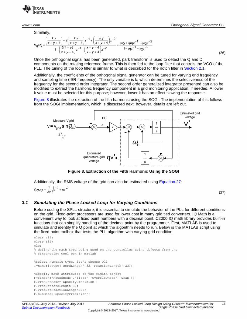
Once the orthogonal signal has been generated, park transform is used to detect the Q and Dcomponents on the rotating reference frame. This is then fed to the loop filter that controls the VCO of thePLL. The tuning of the loop filter is similar to what is described for the notch filter in Section 2.1.
Additionally, the coefficients of the orthogonal signal generator can be tuned for varying grid frequencyand sampling time (ISR frequency). The only variable is k, which determines the selectiveness of thefrequency for the second order integrator. The second order generalized integrator presented can also bemodified to extract the harmonic frequency component in a grid monitoring application, if needed. A lowerk value must be selected for this purpose; however, lower k has an effect slowing the response.
Figure 8 illustrates the extraction of the fifth harmonic using the SOGI. The implementation of this followsfrom the SOGI implementation, which is discussed next; however, details are left out.
Figure 8. Extraction of the Fifth Harmonic Using the SOGI
Additionally, the RMS voltage of the grid can also be estimated using Equation 27:
(27)
3.1 Simulating the Phase Locked Loop for Varying ConditionsBefore coding the SPLL structure, it is essential to simulate the behavior of the PLL for different conditionson the grid. Fixed-point processors are used for lower cost in many grid tied converters. IQ Math is aconvenient way to look at fixed point numbers with a decimal point. C2000 IQ math library provides built-infunctions that can simplify handling of the decimal point by the programmer. First, MATLAB is used tosimulate and identify the Q point at which the algorithm needs to run. Below is the MATLAB script usingthe fixed-point toolbox that tests the PLL algorithm with varying grid condition.clear all;close all;clc;% define the math type being used on the controller using objects from the% fixed-point tool box in matlab
%Select numeric type, let's choose Q23T=numerictype('WordLength',32,'FractionLength',23);
%Specify math attributes to the fimath objectF=fimath('RoundMode','floor','OverflowMode','wrap');F.ProductMode='SpecifyPrecision';F.ProductWordLength=32;F.ProductFractionLength=23;F.SumMode='SpecifyPrecision';

Orthogonal Signal Generator PLL www.ti.com
16 SPRABT3A–July 2013–Revised July 2017Submit Documentation Feedback
Copyright © 2013–2017, Texas Instruments Incorporated
Software Phase Locked Loop Design Using C2000™ Microcontrollers forSingle Phase Grid Connected Inverter
F.SumWordLength=32;F.SumFractionLength=23;
%specify fipref object, to display warning in cases of overflow and%underflowP=fipref;P.LoggingMode='on';P.NumericTypeDisplay='none';P.FimathDisplay='none';
%PLL Modelling starts from hereFs=50000; %Sampling frequency = 50KhzGridFreq=50; %Nominal Grid Frequency in HzTfinal=0.2; %Time the simulation is run for = 0.5 seconds
Ts=1/Fs; %Sampling Time = 1/Fst=0:Ts:Tfinal; %Simulation Time vectorwn=2*pi*GridFreq; %Nominal Grid Frequency in radians
%declare arrays used by the PLL processerr=fi([0,0,0,0,0],T,F);ylf=fi([0,0,0,0,0],T,F);Mysin=fi([0,0,0,0,0],T,F);Mycos=fi([1,1,1,1,1],T,F);theta=fi([0,0,0,0,0],T,F);dc_err=fi([0,0,0,0,0],T,F);wo=fi(0,T,F);
% used for plottingPlot_Var=fi([0,0,0,0],T,F);Plot_theta=fi([0,0,0,0],T,F);Plot_osgu=fi([0,0,0,0],T,F);Plot_osgqu=fi([0,0,0,0],T,F);Plot_D=fi([0,0,0,0],T,F);Plot_Q=fi([0,0,0,0],T,F);Plot_dc_err=fi([0,0,0,0,0],T,F);
%orthogonal signal generator%using trapezoidal approximationosg_k=0.5;osg_x=2*osg_k*wn*Ts;osg_y=(wn*wn*Ts*Ts);osg_b0=osg_x/(osg_x+osg_y+4);osg_b2=-1*osg_b0;osg_a1=(2*(4-osg_y))/(osg_x+osg_y+4);osg_a2=(osg_x-osg_y-4)/(osg_x+osg_y+4);
osg_qb0=(osg_k*osg_y)/(osg_x+osg_y+4);osg_qb1=2*osg_qb0;osg_qb2=osg_qb0;
osg_k=fi(osg_k,T,F);osg_x=fi(osg_x,T,F);osg_y=fi(osg_y,T,F);osg_b0=fi(osg_b0,T,F);osg_b2=fi(osg_b2,T,F);osg_a1=fi(osg_a1,T,F);osg_a2=fi(osg_a2,T,F);osg_qb0=fi(osg_qb0,T,F);osg_qb1=fi(osg_qb1,T,F);osg_qb2=fi(osg_qb2,T,F);
osg_u=fi([0,0,0,0,0,0],T,F);osg_qu=fi([0,0,0,0,0,0],T,F);

www.ti.com Orthogonal Signal Generator PLL
17SPRABT3A–July 2013–Revised July 2017Submit Documentation Feedback
Copyright © 2013–2017, Texas Instruments Incorporated
Software Phase Locked Loop Design Using C2000™ Microcontrollers forSingle Phase Grid Connected Inverter
u_Q=fi([0,0,0],T,F);u_D=fi([0,0,0],T,F);
%generate input signal
% CASE 1 : Phase Jump at the Mid PointL=length(t);for n=1:floor(L)
u(n)=sin(2*pi*GridFreq*Ts*n);endfor n=1:floor(L)
u1(n)=sin(2*pi*GridFreq*Ts*n);end
for n=floor(L/2):Lu(n)=sin(2*pi*GridFreq*Ts*n+pi/2);
end
u=fi(u,T,F);
% simulate the PLL processfor n=3:Tfinal/Ts % No of iteration of the PLL process in the simulation time
%Orthogonal Signal Generatorosg_u(1)=(osg_b0*(u(n)-u(n-2)))+osg_a1*osg_u(2)+osg_a2*osg_u(3);osg_u(3)=osg_u(2);osg_u(2)=osg_u(1);
osg_qu(1)=(osg_qb0*u(n)+osg_qb1*u(n-1)+osg_qb2*u(n-2))+osg_a1*osg_qu(2)+osg_a2*osg_qu(3);osg_qu(3)=osg_qu(2);osg_qu(2)=osg_qu(1);
%park trasnform from alpha beta to d-q axisu_Q(1)=Mycos(2)*osg_u(1)+Mysin(2)*osg_qu(1);u_D(1)=-Mysin(2)*osg_u(1)+Mycos(2)*osg_qu(1);
%Loop Filterylf(1)=fi(1,T,F)*ylf(2)+fi(166.877556,T,F)*u_Q(1)+fi(-166.322444,T,F)*u_Q(2);
u_Q(2)=u_Q(1);u_D(2)=u_D(1);
%Limit LF according to its Q? size pipelineylf(1)=max([ylf(1) fi(-128,T,F)]);ylf(1)=min([ylf(1) fi(128,T,F)]);
ylf(2)=ylf(1);
%update output frequencywo=GridFreq+ylf(1);
%update the output phasetheta(1)=theta(2)+wo*fi(Ts,T,F);
if(theta(1)>fi(1.0,T,F))theta(1)=fi(0,T,F);
end
theta(2)=theta(1);Mysin(1)=sin(theta(1)*fi(2*pi,T,F));Mycos(1)=cos(theta(1)*fi(2*pi,T,F));Mysin(2)=Mysin(1);Mycos(2)=Mycos(1);
Plot_theta(n+1)=theta(1);Plot_osgu(n+1)=osg_u(1);

(a) (b)
(c) (d)
0 0.02 0.04 0.06 0.08 0.1 0.12 0.14 0.16 0.18 0.2-1
0
1SPLL(red) & Ideal Grid(blue)
0 0.02 0.04 0.06 0.08 0.1 0.12 0.14 0.16 0.18 0.2-2
0
2Error
0 0.02 0.04 0.06 0.08 0.1 0.12 0.14 0.16 0.18 0.2-1
0
1SPLL Out(Blue) & Ideal Grid(Red)
0 0.02 0.04 0.06 0.08 0.1 0.12 0.14 0.16 0.18 0.2-1
0
1SPLL(red) & Ideal Grid(blue)
0 0.02 0.04 0.06 0.08 0.1 0.12 0.14 0.16 0.18 0.2-0.5
0
0.5Error
0 0.02 0.04 0.06 0.08 0.1 0.12 0.14 0.16 0.18 0.2-1
0
1SPLL Out(Blue) & Ideal Grid(Red)
0 0.02 0.04 0.06 0.08 0.1 0.12 0.14 0.16 0.18 0.2-1
0
1SPLL(red) & Ideal Grid(blue)
0 0.02 0.04 0.06 0.08 0.1 0.12 0.14 0.16 0.18 0.2-2
0
2Error
0 0.02 0.04 0.06 0.08 0.1 0.12 0.14 0.16 0.18 0.2-1
0
1SPLL Out(Blue) & Ideal Grid(Red)
0 0.02 0.04 0.06 0.08 0.1 0.12 0.14 0.16 0.18 0.2-1
0
1SPLL(red) & Ideal Grid(blue)
0 0.02 0.04 0.06 0.08 0.1 0.12 0.14 0.16 0.18 0.2-0.5
0
0.5Error
0 0.02 0.04 0.06 0.08 0.1 0.12 0.14 0.16 0.18 0.2-1
0
1SPLL Out(Blue) & Ideal Grid(Red)
Orthogonal Signal Generator PLL www.ti.com
18 SPRABT3A–July 2013–Revised July 2017Submit Documentation Feedback
Copyright © 2013–2017, Texas Instruments Incorporated
Software Phase Locked Loop Design Using C2000™ Microcontrollers forSingle Phase Grid Connected Inverter
Plot_osgqu(n+1)=osg_qu(1);Plot_Var(n+1)=Mysin(1);Plot_D(n+1)=u_D(1);Plot_Q(n+1)=u_Q(1);
end
% CASE 1 : Phase Jump at the Mid Pointerror=Plot_Var-u;
%CASE 2 : Harmonics%error=Plot_Var-u1;
%CASE 3: Frequency Variations%error=Plot_Var-u;
%CASE 4: Amplitude Variations%error=Plot_Var-u1;
subplot(3,1,1),plot(t,Plot_Var,'r',t,u,'b'),title('SPLL(red) & Ideal Grid(blue)');subplot(3,1,2),plot(t,error,'r'),title('Error');subplot(3,1,3),plot(t,u1,'r',t,Plot_Var,'b'),title('SPLL Out(Blue) & Ideal Grid(Red)');
Figure 9 shows the results of the varying condition on the PLL.
A Phase Jump of 90°B Phase Jump of 90°C Frequency drift at mid point highlights the need for adaptive notch filterD Amplitude change (Voltage Sags and Dips)
Figure 9. PLL Response to Varying Grid Conditions

www.ti.com Orthogonal Signal Generator PLL
19SPRABT3A–July 2013–Revised July 2017Submit Documentation Feedback
Copyright © 2013–2017, Texas Instruments Incorporated
Software Phase Locked Loop Design Using C2000™ Microcontrollers forSingle Phase Grid Connected Inverter
3.2 Implementing PLL on C2000 Controller Using IQ MathAs the regular inverter typically uses IQ24, and as shown in Section 3.1, the Q point chosen for the PLL isIQ23. The code for the PLL can be written as follows:#ifndef SPLL_1ph_SOGI_H_#define SPLL_1ph_SOGI_H_
#define SPLL_SOGI_Q _IQ23#define SPLL_SOGI_Qmpy _IQ23mpy#define SPLL_SOGI_SINE _IQ23sin#define SPLL_SOGI_COS _IQ23cos
//*********** Structure Definition ********//typedef struct{
int32 osg_k;int32 osg_x;int32 osg_y;int32 osg_b0;int32 osg_b2;int32 osg_a1;int32 osg_a2;int32 osg_qb0;int32 osg_qb1;int32 osg_qb2;
}SPLL_SOGI_OSG_COEFF;
typedef struct{int32 B1_lf;int32 B0_lf;int32 A1_lf;
}SPLL_SOGI_LPF_COEFF;
typedef struct{int32 u[3]; // Ac Inputint32 osg_u[3];int32 osg_qu[3];int32 u_Q[2];int32 u_D[2];int32 ylf[2];int32 fo; // output frequency of PLLint32 fn; //nominal frequencyint32 theta[2];int32 cos;int32 sin;int32 delta_T;SPLL_SOGI_OSG_COEFF osg_coeff;SPLL_SOGI_LPF_COEFF lpf_coeff;
}SPLL_1ph_SOGI;
//*********** Function Declarations *******//inline void SPLL_1ph_SOGI_init(int Grid_freq, long DELTA_T, volatile SPLL_1ph_SOGI *spll,volatile SPLL_SOGI_LPF_COEFF lpf_coeff);inline void SPLL_1ph_SOGI_coeff_update(float delta_T, float wn, volatile SPLL_1ph_SOGI *spll);inline void SPLL_1ph_SOGI_run_FUNC(SPLL_1ph_SOGI *spll1);
//*********** Structure Init Function ****//inline void SPLL_1ph_SOGI_init(int Grid_freq, long DELTA_T, volatile SPLL_1ph_SOGI *spll_obj,volatile SPLL_SOGI_LPF_COEFF lpf_coeff){
spll_obj->u[0]=SPLL_SOGI_Q(0.0);spll_obj->u[1]=SPLL_SOGI_Q(0.0);spll_obj->u[2]=SPLL_SOGI_Q(0.0);
spll_obj->osg_u[0]=SPLL_SOGI_Q(0.0);spll_obj->osg_u[1]=SPLL_SOGI_Q(0.0);spll_obj->osg_u[2]=SPLL_SOGI_Q(0.0);

Orthogonal Signal Generator PLL www.ti.com
20 SPRABT3A–July 2013–Revised July 2017Submit Documentation Feedback
Copyright © 2013–2017, Texas Instruments Incorporated
Software Phase Locked Loop Design Using C2000™ Microcontrollers forSingle Phase Grid Connected Inverter
spll_obj->osg_qu[0]=SPLL_SOGI_Q(0.0);spll_obj->osg_qu[1]=SPLL_SOGI_Q(0.0);spll_obj->osg_qu[2]=SPLL_SOGI_Q(0.0);
spll_obj->u_Q[0]=SPLL_SOGI_Q(0.0);spll_obj->u_Q[1]=SPLL_SOGI_Q(0.0);
spll_obj->u_D[0]=SPLL_SOGI_Q(0.0);spll_obj->u_D[1]=SPLL_SOGI_Q(0.0);
spll_obj->ylf[0]=SPLL_SOGI_Q(0.0);spll_obj->ylf[1]=SPLL_SOGI_Q(0.0);
spll_obj->fo=SPLL_SOGI_Q(0.0);spll_obj->fn=SPLL_SOGI_Q(Grid_freq);
spll_obj->theta[0]=SPLL_SOGI_Q(0.0);spll_obj->theta[1]=SPLL_SOGI_Q(0.0);
spll_obj->sin=SPLL_SOGI_Q(0.0);spll_obj->cos=SPLL_SOGI_Q(0.0);
//coefficients for the loop filterspll_obj->lpf_coeff.B1_lf=lpf_coeff.B1_lf;spll_obj->lpf_coeff.B0_lf=lpf_coeff.B0_lf;spll_obj->lpf_coeff.A1_lf=lpf_coeff.A1_lf;
spll_obj->delta_T=DELTA_T;
}
//*********** Structure Coeff Update *****//inline void SPLL_1ph_SOGI_coeff_update(float delta_T, float wn, volatile SPLL_1ph_SOGI *spll){
float osgx,osgy,temp;spll->osg_coeff.osg_k=SPLL_SOGI_Q(0.5);osgx=(float)(2.0*0.5*wn*delta_T);spll->osg_coeff.osg_x=SPLL_SOGI_Q(osgx);osgy=(float)(wn*delta_T*wn*delta_T);spll->osg_coeff.osg_y=SPLL_SOGI_Q(osgy);temp=(float)1.0/(osgx+osgy+4.0);spll->osg_coeff.osg_b0=SPLL_SOGI_Q((float)osgx*temp);spll->osg_coeff.osg_b2=SPLL_SOGI_Qmpy(SPLL_SOGI_Q(-1.0),spll->osg_coeff.osg_b0);spll->osg_coeff.osg_a1=SPLL_SOGI_Q((float)(2.0*(4.0-osgy))*temp);spll->osg_coeff.osg_a2=SPLL_SOGI_Q((float)(osgx-osgy-4)*temp);spll->osg_coeff.osg_qb0=SPLL_SOGI_Q((float)(0.5*osgy)*temp);spll->osg_coeff.osg_qb1=SPLL_SOGI_Qmpy(spll-
>osg_coeff.osg_qb0,SPLL_SOGI_Q(2.0));spll->osg_coeff.osg_qb2=spll->osg_coeff.osg_qb0;
}
//*********** Function Definition ********//inline void SPLL_1ph_SOGI_run_FUNC(SPLL_1ph_SOGI *spll_obj){
// Update the spll_obj->u[0] with the grid value before calling this routine
//-------------------------------//// Orthogonal Signal Generator ////-------------------------------//spll_obj->osg_u[0]=SPLL_SOGI_Qmpy(spll_obj->osg_coeff.osg_b0,(spll_obj->u[0]-
spll_obj->u[2]))+SPLL_SOGI_Qmpy(spll_obj->osg_coeff.osg_a1,spll_obj->osg_u[1])+SPLL_SOGI_Qmpy(spll_obj->osg_coeff.osg_a2,spll_obj->osg_u[2]);
spll_obj->osg_u[2]=spll_obj->osg_u[1];spll_obj->osg_u[1]=spll_obj->osg_u[0];

www.ti.com Orthogonal Signal Generator PLL
21SPRABT3A–July 2013–Revised July 2017Submit Documentation Feedback
Copyright © 2013–2017, Texas Instruments Incorporated
Software Phase Locked Loop Design Using C2000™ Microcontrollers forSingle Phase Grid Connected Inverter
spll_obj->osg_qu[0]=SPLL_SOGI_Qmpy(spll_obj->osg_coeff.osg_qb0,spll_obj->u[0])+SPLL_SOGI_Qmpy(spll_obj->osg_coeff.osg_qb1,spll_obj->u[1])+SPLL_SOGI_Qmpy(spll_obj->osg_coeff.osg_qb2,spll_obj->u[2])+SPLL_SOGI_Qmpy(spll_obj-
>osg_coeff.osg_a1,spll_obj->osg_qu[1])+SPLL_SOGI_Qmpy(spll_obj->osg_coeff.osg_a2,spll_obj->osg_qu[2]);
spll_obj->osg_qu[2]=spll_obj->osg_qu[1];spll_obj->osg_qu[1]=spll_obj->osg_qu[0];
spll_obj->u[2]=spll_obj->u[1];spll_obj->u[1]=spll_obj->u[0];
//-------------------------------------------------------//// Park Transform from alpha beta to d-q axis ////-------------------------------------------------------//spll_obj->u_Q[0]=SPLL_SOGI_Qmpy(spll_obj->cos,spll_obj-
>osg_u[0])+SPLL_SOGI_Qmpy(spll_obj->sin,spll_obj->osg_qu[0]);spll_obj->u_D[0]=SPLL_SOGI_Qmpy(spll_obj->cos,spll_obj->osg_qu[0])-
SPLL_SOGI_Qmpy(spll_obj->sin,spll_obj->osg_u[0]);
//---------------------------------//// Loop Filter //
/---------------------------------//spll_obj->ylf[0]=spll_obj->ylf[1]+SPLL_SOGI_Qmpy(spll_obj-
>lpf_coeff.B0_lf,spll_obj->u_Q[0])+SPLL_SOGI_Qmpy(spll_obj->lpf_coeff.B1_lf,spll_obj->u_Q[1]);//spll_obj->ylf[0]=(spll_obj->ylf[0]>SPLL_SOGI_Q(20.0))?SPLL_SOGI_Q(20.0):spll_obj-
>ylf[0];//spll_obj->ylf[0]=(spll_obj->ylf[0] < SPLL_SOGI_Q(-20.0))?SPLL_SOGI_Q(-
20.0):spll_obj->ylf[0];spll_obj->ylf[1]=spll_obj->ylf[0];
spll_obj->u_Q[1]=spll_obj->u_Q[0];//spll_obj->u_D[1]=spll_obj->u_D[0];
//---------------------------------//// VCO ////---------------------------------//spll_obj->fo=spll_obj->fn+spll_obj->ylf[0];
spll_obj->theta[0]=spll_obj->theta[1]+SPLL_SOGI_Qmpy(SPLL_SOGI_Qmpy(spll_obj->fo,spll_obj->delta_T),SPLL_SOGI_Q(2*3.1415926));
if(spll_obj->theta[0]>SPLL_SOGI_Q(2*3.1415926))spll_obj->theta[0]=spll_obj->theta[0]-SPLL_SOGI_Q(2*3.1415926);
spll_obj->theta[1]=spll_obj->theta[0];
spll_obj->sin=SPLL_SOGI_SINE(spll_obj->theta[0]);spll_obj->cos=SPLL_SOGI_COS(spll_obj->theta[0]);
}
//*********** Macro Definition ***********//#define SPLL_1ph_SOGI_run_MACRO(v) \
v.osg_u[0]=SPLL_SOGI_Qmpy(v.osg_coeff.osg_b0,(v.u[0]-v.u[2]))+SPLL_SOGI_Qmpy(v.osg_coeff.osg_a1,v.osg_u[1])+SPLL_SOGI_Qmpy(v.osg_coeff.osg_a2,v.osg_u[2]);\
v.osg_u[2]=v.osg_u[1];\v.osg_u[1]=v.osg_u[10];\
v.osg_qu[0]=SPLL_SOGI_Qmpy(v.osg_coeff.osg_qb0,v.u[0])+SPLL_SOGI_Qmpyu(v.osg_coeff.osg_qb1,v.u[1])+SPLL_SOGI_Qmpy(v.osg_coeff.osg_qb2,v.u[2])+SPLL_SOGI_Qmpy(v.osg_coeff.osg_a1,v.osg_qu[1])+
SPLL_SOGI_Qmpy(v.osg_coeff.osg_a2.v.osg_qu[2]);\
v.osg_qu[2]=v.osg_qu[1]; \v.osg_qu[1]=v.osg_qu[0]; \v.u[2]=v.u[1]; \

Read ADC Value and
populate the spll object with
the appropriate Q format
ISR
Call SPLL run FUNC
Run the OSG
Run Park Transform
on the orthogonal
signals
Loop Filter
VCO & calculate
sine and cosine
value from theta
Read the spll sine value and
run the rest of the inverter
code
Exit ISR
Orthogonal Signal Generator PLL www.ti.com
22 SPRABT3A–July 2013–Revised July 2017Submit Documentation Feedback
Copyright © 2013–2017, Texas Instruments Incorporated
Software Phase Locked Loop Design Using C2000™ Microcontrollers forSingle Phase Grid Connected Inverter
v.u[1]=v.u[0]; \v.u_Q[0]=SPLL_SOGI_Qmpy(v.cos,v.osg_u[0])+SPLL_SOGI_Qmpy(v.sin,v.osg_qu[0]); \v.u_D[0]=SPLL_SOGI_Qmpy(v.cos,v.osg_qu[0])-SPLL_SOGI_Qmpy(v.sin,v.osg_u[0]); \
v.ylf[0]=v.ylf[1]+SPLL_SOGI_Qmpy(v.lpf_coeff.B0_lf,v.u_Q[0])+SPLL_SOGI_Qmpy(v.lpf_coeff.B1_lf,v.u_Q[1]); \
v.ylf[1]=v.ylf[0]; \v.u_Q[1]=v.u_Q[0]; \v.fo=v.fn+v.ylf[0]; \
v.theta[0]=v.theta[1]+SPLL_SOGI_Qmpy(SPLL_SOGI_Qmpy(v.fov.v.delta_T),SPLL_Q(2*3.1415926)); \if(v.theta[0]>SPLL_SOGI_Q(2*3.1415926)) \
v.theta[0]=SPLL_SOGI_Q(0.0); \v.theta[1]=v.theta[0]; \v.sin=SPLL_SOGI_SINE(v.theta[0]); \v.cos=SPLL_SOGI_COS(v.theta[0]);
#endif/* SPLL_1ph_SOGI_H_ */
To use this block in an end application, you must include the header file and declare objects for the SPLLstructure and loop filter coefficients.#include "SPLL_1ph_SOGI.h"SPLL_1ph_SOGI spll1;SPLL_SOGI_LPF_COEFF spll_lpf_coef1;
From the analysis in Section 2.1, the loop filter coefficients are known, write these into the spll lpf coeffstructure.#define B0_LPF SPLL_SOGI_Q(166.877556)#define B1_LPF SPLL_SOGI_Q(-166.322444)#define A1_LPF SPLL_SOGI_Q(-1.0)spll_lpf_coef1.B0_lf=B0_LPF;spll_lpf_coef1.B1_lf=B1_LPF;spll_lpf_coef1.A1_lf=A1_LPF;
Call the SPLL_1ph_SOGI_init routine with the frequency of the ISR. The SPLL will be executed in as theparameter and the grid frequency and then call the notch filter update coefficient update routine.SPLL_1ph_SOGI_init(GRID_FREQ,_IQ23((float)(1.0/ISR_FREQUENCY)),&spll2,spll_lpf_coef2);SPLL_1ph_SOGI_coeff_update(((float)(1.0/ISR_FREQUENCY)),(float)(2*PI*GRID_FREQ),&spll2);

www.ti.com Orthogonal Signal Generator PLL
23SPRABT3A–July 2013–Revised July 2017Submit Documentation Feedback
Copyright © 2013–2017, Texas Instruments Incorporated
Software Phase Locked Loop Design Using C2000™ Microcontrollers forSingle Phase Grid Connected Inverter
In the ISR, read the sinusoidal input voltage from the ADC and feed it into the SPLL block, and write toinvsine value with the sinus of the current grid angle. This can then be used in control operations.inv_meas_vol_inst =((long)((long)VAC_FB<<12))-offset_165)<<1;spll1.AC_input=(long)InvSine>>1; // Q24 to Q23SPLL_1ph_SOGI_run_FUNC(&spll1);InvSine=spll2.sin<<1; // shift from Q23 to Q24
3.3 Result of SOGI PLLVery fast transient response is possible as shown in Figure 10.
A Ch1: is the grid sine valueB ch2: is the PLL lockC ch3: is the grid thetaD ch4: is the phase jump
Figure 10. Transient Response

.cos( )θ.Vin
SPLL_1ph
(struct)
wn
.( )θ
.sin( )θ
.cos( )θ.Vin
SPLL_1ph_SOGI
(struct)
wn
.( )θ
.sin( )θ
.cos( )θ.Vq
SPLL_3ph_SRF
(struct)
wn
.( )θ
.sin( )θ
.cos( )θ
.Vd+
SPLL_3ph_DDSRF
(struct)
wn
.( )θ
.sin( )θ.Vq+
.Vq-
.Vd-
.Vpv
MPPT_PnO
(struct)
StepSize
.VmppOut
.Ipv
.Vd.Va
.Vb
ABC_DQ0_Pos
(struct)
.Vc
.sin( )θ
.cos( )θ
.Vq
.Vz
dq
ω
Solar Library and ControlSuite™ www.ti.com
24 SPRABT3A–July 2013–Revised July 2017Submit Documentation Feedback
Copyright © 2013–2017, Texas Instruments Incorporated
Software Phase Locked Loop Design Using C2000™ Microcontrollers forSingle Phase Grid Connected Inverter
4 Solar Library and ControlSuite™C2000 provides software for development of control application using C2000 devices. The software isavailable for download from http://www.ti.com/controlSUITE.
Various library, like the IQ math Library and Solar Library, simplify the design and development ofalgorithms on the C2000 device. IQ math library provides a convenient way to easily translate the fixed-point toolbox code into controller code.
The solar library provides the software blocks discussed in this application report, and many more.
5 References• Francisco D. Freijedo et al, “Robust Phase Locked Loops Optimized for DSP implementation in Power
Quality Applications”, IECON 2008, 3052-3057• TMS320F28030, TMS320F28031, TMS320F28032, TMS320F28033, TMS320F28034,
TMS320F28035 Piccolo Microcontrollers Data Manual (SPRS584)• C2000 controlSUITE• Marco Liserre, Pedro Rodriguez Remus Teodrescu, Grid Converters for Phototvoltaic and Wind Power
Systems: John Wiley & Sons Ltd., 2011.• P. Rodriguez et al, "Double Synchronous Reference Frame PLL for Power Converters Control," vol.
22, no. 2, 2007.

www.ti.com Revision History
25SPRABT3A–July 2013–Revised July 2017Submit Documentation Feedback
Copyright © 2013–2017, Texas Instruments Incorporated
Revision History
Revision HistoryNOTE: Page numbers for previous revisions may differ from page numbers in the current version.
Changes from Original (July 2013) to A Revision ........................................................................................................... Page
• Changes were made in Section 2.1..................................................................................................... 4

IMPORTANT NOTICE FOR TI DESIGN INFORMATION AND RESOURCES
Texas Instruments Incorporated (‘TI”) technical, application or other design advice, services or information, including, but not limited to,reference designs and materials relating to evaluation modules, (collectively, “TI Resources”) are intended to assist designers who aredeveloping applications that incorporate TI products; by downloading, accessing or using any particular TI Resource in any way, you(individually or, if you are acting on behalf of a company, your company) agree to use it solely for this purpose and subject to the terms ofthis Notice.TI’s provision of TI Resources does not expand or otherwise alter TI’s applicable published warranties or warranty disclaimers for TIproducts, and no additional obligations or liabilities arise from TI providing such TI Resources. TI reserves the right to make corrections,enhancements, improvements and other changes to its TI Resources.You understand and agree that you remain responsible for using your independent analysis, evaluation and judgment in designing yourapplications and that you have full and exclusive responsibility to assure the safety of your applications and compliance of your applications(and of all TI products used in or for your applications) with all applicable regulations, laws and other applicable requirements. Yourepresent that, with respect to your applications, you have all the necessary expertise to create and implement safeguards that (1)anticipate dangerous consequences of failures, (2) monitor failures and their consequences, and (3) lessen the likelihood of failures thatmight cause harm and take appropriate actions. You agree that prior to using or distributing any applications that include TI products, youwill thoroughly test such applications and the functionality of such TI products as used in such applications. TI has not conducted anytesting other than that specifically described in the published documentation for a particular TI Resource.You are authorized to use, copy and modify any individual TI Resource only in connection with the development of applications that includethe TI product(s) identified in such TI Resource. NO OTHER LICENSE, EXPRESS OR IMPLIED, BY ESTOPPEL OR OTHERWISE TOANY OTHER TI INTELLECTUAL PROPERTY RIGHT, AND NO LICENSE TO ANY TECHNOLOGY OR INTELLECTUAL PROPERTYRIGHT OF TI OR ANY THIRD PARTY IS GRANTED HEREIN, including but not limited to any patent right, copyright, mask work right, orother intellectual property right relating to any combination, machine, or process in which TI products or services are used. Informationregarding or referencing third-party products or services does not constitute a license to use such products or services, or a warranty orendorsement thereof. Use of TI Resources may require a license from a third party under the patents or other intellectual property of thethird party, or a license from TI under the patents or other intellectual property of TI.TI RESOURCES ARE PROVIDED “AS IS” AND WITH ALL FAULTS. TI DISCLAIMS ALL OTHER WARRANTIES ORREPRESENTATIONS, EXPRESS OR IMPLIED, REGARDING TI RESOURCES OR USE THEREOF, INCLUDING BUT NOT LIMITED TOACCURACY OR COMPLETENESS, TITLE, ANY EPIDEMIC FAILURE WARRANTY AND ANY IMPLIED WARRANTIES OFMERCHANTABILITY, FITNESS FOR A PARTICULAR PURPOSE, AND NON-INFRINGEMENT OF ANY THIRD PARTY INTELLECTUALPROPERTY RIGHTS.TI SHALL NOT BE LIABLE FOR AND SHALL NOT DEFEND OR INDEMNIFY YOU AGAINST ANY CLAIM, INCLUDING BUT NOTLIMITED TO ANY INFRINGEMENT CLAIM THAT RELATES TO OR IS BASED ON ANY COMBINATION OF PRODUCTS EVEN IFDESCRIBED IN TI RESOURCES OR OTHERWISE. IN NO EVENT SHALL TI BE LIABLE FOR ANY ACTUAL, DIRECT, SPECIAL,COLLATERAL, INDIRECT, PUNITIVE, INCIDENTAL, CONSEQUENTIAL OR EXEMPLARY DAMAGES IN CONNECTION WITH ORARISING OUT OF TI RESOURCES OR USE THEREOF, AND REGARDLESS OF WHETHER TI HAS BEEN ADVISED OF THEPOSSIBILITY OF SUCH DAMAGES.You agree to fully indemnify TI and its representatives against any damages, costs, losses, and/or liabilities arising out of your non-compliance with the terms and provisions of this Notice.This Notice applies to TI Resources. Additional terms apply to the use and purchase of certain types of materials, TI products and services.These include; without limitation, TI’s standard terms for semiconductor products http://www.ti.com/sc/docs/stdterms.htm), evaluationmodules, and samples (http://www.ti.com/sc/docs/sampterms.htm).
Mailing Address: Texas Instruments, Post Office Box 655303, Dallas, Texas 75265Copyright © 2017, Texas Instruments Incorporated