soil bioengineering for upland slope stabilization
TRANSCRIPT

Research ReportResearch Project WA-RD 491.1Soil Bioengineering for Slopes
SOIL BIOENGINEERING FORUPLAND SLOPE STABILIZATION
by
Lisa Lewis Sandra L. SalisburyPrincipal Investigator Landscape DesignerUSDA Forest Service Washington State Department of Transportation
National Riparian Service Team Roadside and Site Development UnitBureau of Land Management Office PO Box 47329
PO Box 550 Olympia, WA 98504-7329Prineville, Oregon 97754
Shannon HagenResearch Assistant
Washington State Department of TransportationRoadside and Site Development Unit
PO Box 47329Olympia, WA 98504-7329
Washington State Transportation Center (TRAC)University of Washington, Box 354802
University District Building1107 NE 45th Street, Suite 535
Seattle, Washington 98105-4631
Washington State Department of TransportationTechnical Monitor
Mark Maurer, L.A., Roadside and Site Development Manager
February 2001

TECHNICAL REPORT STANDARD TITLE PAGE1. REPORT NO. 2. GOVERNMENT ACCESSION NO. 3. RECIPIENT'S CATALOG NO.
WA-RD 491.1
4. TITLE AND SUBTITLE 5. REPORT DATE
SOIL BIOENGINEERING FOR SLOPE STABILIZATION February 20016. PERFORMING ORGANIZATION CODE
7. AUTHOR(S) 8. PERFORMING ORGANIZATION REPORT NO.
Lisa Lewis, Shannon Hagen, and Sandra Salisbury
9. PERFORMING ORGANIZATION NAME AND ADDRESS 10. WORK UNIT NO.
Lisa LewisNational Riparian Service Team 11. CONTRACT OR GRANT NO.
USDA, Forest Servicec/o Bureau of Land ManagementPO Box 550Prineville, OR 9775412. SPONSORING AGENCY NAME AND ADDRESS 13. TYPE OF REPORT AND PERIOD COVERED
Washington State Department of TransportationPO Box 47329
Research Report
Olympia, Washington 98504-7370 14. SPONSORING AGENCY CODE
Program Manager: Jim Schafer 360-705-797115. SUPPLEMENTARY NOTES
This study was conducted in cooperation with WSDOT, National Riparian Service Team (USDA ForestService, Bureau of Land Management, Natural Resource Conservation Service), Washington StateDepartment of Ecology, and the Washington Conservation Corps.16. ABSTRACT
The objective of the study was to provide alternatives called soil bioengineering methods for slopeand shallow rapid landslide stabilization along different roadside environments. Additional objectives wereto educate WSDOT personnel in site selection, soil bioengineering techniques, and construction; to providesoil bioengineering decision-making skills. Three study sites were selected: based upon the followingcriteria: safety, visibility, accessibility, representation of disparate moisture conditions, climate, and erosiontypes, illustration of different techniques, availability of additional funding, and WSDOT input. Threedifferent combinations of soil bioengineering techniques were used to stabilize upland slopes on theroadside. Results indicate soil bioengineering is an effective means of upland slope stabilization onerosional slopes and shallow rapid landslides and is practical and economical. Composted biosolidsimproved soil workability and enhanced the native plant community during the first year.
17. KEY WORDS 18. DISTRIBUTION STATEMENT
Soil bioengineering, slope stabilization, erosion,erosion control, landslides, native plants, cribwall,fascine, branchpacking, brush layering, cordon, livecribwall, live gully repair, live staking, willow wall,biosolids, cost/benefit
No restrictions. This document is available to thepublic through the National Technical InformationService, Springfield, VA 22616
19. SECURITY CLASSIF. (of this report) 20. SECURITY CLASSIF. (of this page) 21. NO. OF PAGES 22. PRICE
None None 96

iii
DISCLAIMER
The contents of this report reflect the views of the authors, who are responsible
for the facts and the accuracy of the data represented herein. The contents do not
necessarily reflect the official views or policies of the Washington State Transportation
Commission, Department of Transportation, or the Federal Highway Administration.
This report does not constitute a standard, specification, or regulation.

TABLE OF CONTENTS
EXECUTIVE SUMMARY...............................................................................................vii
Research Objective .....................................................................................................vii
Project Sites ................................................................................................................vii
Project Effort .............................................................................................................viii
Outcomes ...................................................................................................................viii
INTRODUCTION............................................................................................................... 1
Problem Statement........................................................................................................ 1
Research Objectives...................................................................................................... 2
METHODS.......................................................................................................................... 3
Site Selection ................................................................................................................ 3
Chelan ........................................................................................................................... 3
Lost Creek, SR 101, MP 174 ........................................................................................ 8
Raymond, SR 101, MP 60.35 ..................................................................................... 20
FINDINGS AND DISCUSSION ...................................................................................... 28
Chelan ......................................................................................................................... 28
Lost Creek................................................................................................................... 31
Raymond..................................................................................................................... 33
COST/BENEFIT ANALYSIS........................................................................................... 36
Purpose ....................................................................................................................... 36
Methodology............................................................................................................... 36
Data Sources ............................................................................................................... 40
Findings ...................................................................................................................... 40
CONCLUSIONS AND RECOMMENDATIONS............................................................ 45
Conclusions................................................................................................................. 45
Recommendations....................................................................................................... 46
Limitations of the Study ............................................................................................. 46
Outcomes .................................................................................................................... 47
ACKNOWLEDGMENTS................................................................................................. 49

BIBLIOGRAPHY ............................................................................................................. 50
Soil Bioengineering Methods ..................................................................................... 50
Benefit/Cost Analysis ................................................................................................. 52
Soil Bioengineering History ....................................................................................... 52
APPENDIX A: PROJECT PARTICIPANTS .................................................................... 1
APPENDIX B: DEFINITIONS.......................................................................................... 1
APPENDIX C: LITERATURE REVIEW .......................................................................... 1
APPENDIX D: CHECKLIST FOR EVALUATING EROSION SITES.......................... 1
APPENDIX E: MONITORING FORM............................................................................. 1
APPENDIX F: METHODS: FURTHER DETAILS.................................................... F-1
APPENDIX G: COMPOST APPLICATION WORKSHEET ............................... G-1
APPENDIX H: PLANT LIST FOR APRIL 99 FIELDTRIP ....................................... H-1
APPENDIX I: CHELAN GRADING PLAN................................................................. I-1
APPENDIX J: CHELAN PLANTING PLAN .............................................................J-1
APPENDIX K: LOST CREEK SOIL BIOENGINEERING PLAN .......................... K-1
APPENDIX L: LOST CREEK SITE PLAN................................................................. L-1
APPENDIX M: RAYMOND SOIL BIOENGINEERING PLAN ................................M-1
EXECUTIVE SUMMARY
RESEARCH OBJECTIVE
The purpose of this research project was to present viable soil bioengineering
alternatives, or “living” approaches, to slope stabilization. This is not to argue that soil
bioengineering is better than traditional engineering treatments, but to introduce the
concept of soil bioengineering, to expand on the knowledge of the Washington State
Department of Transportation (WSDOT) personnel, to provide additional alternatives,
and to encourage integration of these two practices. Specifically, this report provides
field personnel with examples of soil bioengineering restoration techniques intended
primarily for upland roadside slope stabilization and revegetation. There are numerous
soil bioengineering techniques, and multiple methods are often combined to stabilize one
erosion feature. An additional goal of this project was to improve communication
between disciplines within WSDOT.
PROJECT SITES
After a team field review of over 88 potential sites throughout most of
Washington State, three project sites were selected by the Principal Investigator (PI).
These sites were chosen on the basis of the following criteria:
• safety of the public and work crews (both road and slope-related safety issues were addressed)
• visibility and accessibility for educational opportunities
• representation of the disparate soil moisture conditions, climate, and erosion types common to Washington State
• illustration of soil bioengineering techniques that could be used on large erosion sites, small erosion sites, and combined soil bioengineering and traditional engineering treatments
• allocated dollars and the availability of additional funding
• recommendations by WSDOT personnel.

The three selected sites were located in three regions of Washington State:
• Chelan - North Central Region
• Lost Creek/Forks - Olympic Region
• Raymond - Southwest Region.
PROJECT EFFORT
A combination of WSDOT research, road maintenance, engineering, and
environmental funding was used to conduct three large soil bioengineering projects from
November 1999 through April 2000.
Challenges were encountered on all three sites and resulted in design changes and
additional learning opportunities. Maintenance personnel were actively involved in
excavation and construction on the Raymond site and in the selection of the heavy
equipment contractor for the Chelan excavation. Six Washington Conservation Corps
(WCC) crews, comprising 42 crew members, participated in the construction of the three
soil bioengineering projects. The soil bioengineering work involved the following:
• willow wall construction • willow walls with a brush layer base • live cribwall construction • cordon construction • live fascine construction • cedar bender board fencing • planting diverse native vegetation • seeding • biosolid application on the Lost Creek and Chelan sites.
OUTCOMES
• Using multiple soil bioengineering techniques, three large upland slope stabilization projects were constructed.
• The PI and the research team presented the research findings to WSDOT personnel in January 2001. See Appendix A for research team members.
• The full research report is available on the Olympia Service Center (OSC) Roadside and Site Development Unit internet homepage at http://www.wsdot.wa.gov/eesc/cae/ design/roadside/rm.htm.

• A Soil Bioengineering chapter was written for the Roadside Manual, and the Design Manual soil bioengineering chapter was updated.
• The Federal Highway Administration (FHWA) contracted the OSC Roadside and Site Development Unit to create bioengineering Plans, Specification, and Estimates for the Blaine Road project in southwestern Oregon.
• WSDOT obtained the right to use and reproduce all materials from Lewis, E.A., Soil Bioengineering: An Alternative for Roadside Management: A Practical Guide. United States Forest Service. San Dimas Technology and Development Center. San Dimas, California, 2000.
• Communication among disciplines within WSDOT was enhanced. Opportunities for improved communication have been highlighted in the report.
• Awareness of soil bioengineering as an option for roadside stabilization and erosion control was increased within WSDOT.
• Relations with the public were enhanced by the publication of four articles (two local newspapers, an in-house newsletter, and a nationally distributed magazine) about WSDOT’s use of a natural method of erosion control.

1
INTRODUCTION
Soil bioengineering is the use of plant material, living or dead, to alleviate
environmental problems such as shallow, rapid landslides and eroding slopes and stream
banks. In bioengineering systems, plants are an important structural component. This
approach to slope stabilization requires a true partnership among many disciplines,
including soil scientists, hydrologists, botanists, engineering geologists, maintenance
personnel, civil engineers, and landscape architects.
Soil bioengineering most often mimics nature by using locally available materials
and a minimum of heavy equipment, and it can offer roadside managers an inexpensive
way to resolve local environmental problems. These techniques can also be used in
combination with traditional engineering techniques such as rock or concrete structures.
PROBLEM STATEMENT
Transportation systems provide access and allow utilization of land and resources.
Development priorities usually emphasize access, safety, and economics. Environmental
concerns involve operational and maintenance problems such as surface erosion, plugged
drainage structures, and mass failures.
Transportation systems provide tremendous opportunities and, if properly located
on the landscape with well designed drainage features, can remain stable for years with
negligible effects to adjoining areas. However, roads are often linked to increased rates
of erosion and the accumulation of adverse environmental effects on both aquatic and
terrestrial resources. This has become even more apparent during major winter storm
events in recent years.
This is not new information to road managers. Road maintenance personnel, for
example, face a huge task in maintaining roads under their jurisdiction. Major winter
storms that have resulted in significant increases in road landslides and impacts to
adjoining resources have compounded the road manager’s challenge.
The Washington State Department of Transportation (WSDOT) has been using
soil bioengineering methods since the 1980s. Its early focus was on stream bank

stabilization. In 1995 a soil bioengineering task force was formed to study opportunities
for the application of soil bioengineering methods along state roadways, and the work
group agreed that the time had come for WSDOT to consolidate various soil
bioengineering efforts currently under way in the department. From this work, a chapter
on soil bioengineering was written for WSDOT’s Design Manual--a document used by
all roadway design engineers working for and with WSDOT. This report documents the
planning, design, and construction of three soil bioengineering projects on upland slopes
in the roadside.
RESEARCH OBJECTIVES
The objectives for this study were as follows:
• provide viable alternatives, called soil bioengineering or “living” approaches, for slope and shallow, rapid landslide stabilization along different roadside environments
• educate WSDOT personnel in site selection and evaluation, and soil bioengineering techniques, including construction, monitoring, and maintenance
• provide soil bioengineering decision making skills.
This report documents the project process and its outcomes.

METHODS
SITE SELECTION
The researchers wanted the project to include a combination of fill slope and cut
slope erosional features. The criteria for selection were as follows:
• safety of the public and work crews (road and slope related safety issues were addressed)
• visibility and accessibility for educational opportunities
• representation of the disparate soil moisture conditions, climate, and erosion types common to Washington State
• illustration of techniques that could be used on large erosion sites, small erosion sites, and combined soil bioengineering and traditional engineering treatments
• allocated dollars and the availability of additional funding
• input from WSDOT personnel.
From June 16 through 18, 1999, the research team analyzed the potential of 82
sites. Later in June the PI made additional site visits to slopes on SR 101, SR 14, and SR
3 to view sites requested by maintenance. No fill slope areas met all the site selection
criteria.
Although the original plan had been to work on several smaller sites, because of
the difficulty of working on many sites over long distances in a limited amount of time,
the PI decided to use several techniques on each of the selected sites. The final selection
comprised two west-side sites and one site east of the Cascade Mountains. Two of the
sites, Raymond and Chelan, are considered large sites. The Lost Creek site, near Forks,
was selected because it had a rock apron at the base.
CHELAN
Located at Mile Post 8.22 on State Route 971, above Lake Chelan, this 630-foot-
long by 70-feet-high, north-facing slope has been a chronic source of surface erosion and
ditch maintenance needs.

Geology and Soils Soils on site are composed of glacial deposits and volcanic ash overlying granitic
bedrock. The glacial deposits are composed of sand, gravel, cobbles, and boulders. The
weathering of the granite bedrock into rocks, fragments, and mineral components is
called grus; in particular, the feldspar minerals weather rapidly to a fine or "ashy" size.
There is evidence, as seen in Figure 1, of chronic surface erosion with rilling and
associated accumulated debris in the ditch line.
Figure 1. SR 971, Mile Post 8.22 vicinity, June 1999
Climate and Moisture During the June 1999 site visit, the soil was moist. This is a north-facing slope
that receives no direct sunshine from fall through spring.
This area receives an average of 10.9 inches of precipitation per year. Snow depth
in January is approximately 5 inches. Average maximum temperature is 85ºF, which
occurs during July. Average minimum temperature is 22.2ºF in January. Further climate
data can be found at: http://www.wrcc.dri.edu/cgi-bin/ cliMAIN.pl?wachel
Existing Vegetation Existing vegetation was sparse on the slope face. It consisted of a bitterbrush
(Purshia tridentata) and ponderosa pine (Pinus ponderosa) community and one willow
(salix exigua). See Appendix H. This vegetation was located on portions of the slope

that were at an angle of repose of 1.5(V):1(H). Where the slope was steeper, no
vegetation grew.
The slope above the vertical lip had an established ponderosa pine community.
The vegetation, especially the mature trees, growing on the edge are at risk because of
continual erosion (see Figure 2).
Figure 2. Vegetation community on stable soils
Opportunities and Constraints This site had some moisture, combined with a favorable slope aspect, high public
visibility, and a large bank of volunteer plants on the slope above. The adjacent
landowners were willing to grant WSDOT a construction easement, allowing an
excavator to flatten the slope angle and increase stabilization of the site.
The team’s engineering geologist said that, traditionally, she would not have
recommended additional work beyond reducing slope steepness. A flatter slope angle
would help reduce surface erosion and provide favorable ground to establish vegetation.
As with traditional engineering methods, soil bioengineering also requires “re-working”
the slope profile, but in addition it incorporates vegetative treatments to accelerate site
recovery while providing a more permanent solution to the erosion problem.

The constraints were the large amount of excavation necessary to lay the slope
back to 1 ½ :1 and the small amount of moisture in the soil during the summer. Because
of the relatively dry conditions, traditional soil bioengineering techniques were altered.
Design Solution After consultations with fellow scientists and lumber experts, the PI’s solution
was to use cedar bender board fencing. The consensus was that the slope would benefit
from terracing, but traditional soil bioengineering plant species, such as willow, would
not be appropriate for these site conditions. As a result, cedar bender board fencing was
used as an alternative to willow walls to reduce the length and steepness of the slope and
to create stable planting platforms for easier establishment of native (dry climate)
vegetation.
Redwood or cedar bender board fencing is essentially a fence supported on a short
layer of shrub or tree stems. Specifically, it is a short retaining wall built of redwood or
cedar bender fencing with a stem layered base. The PI’s original bender board fencing
detail and specifications are found in Figure 3:
Figure 3. Bender board fencing

Construction • North Central Region (NCR) Maintenance and the Environmental Office surveyed,
staked, and created a topographic map of the site.
• NCR Real Estate Services contacted the landowners and obtained a construction easement for work through April 30, 2000.
• NCR Maintenance opted to use a contractor to excavate the vertical lip of the slope. The contractor removed approximately 11,000 cubic yards of material.
• NCR Maintenance provided traffic control during the 5.5 days of excavation.
• The crew constructed ten terraces with bender-board fencing. Figure 4 shows the terraces at the end of the season, on January 13, 1999.
The following species were planted within WSDOT right-of-way:
Service berry (Amelanchier alnifolia) 155
Snow berry (Symphoricarpos albus) 155
Blue Elderberry (Sambucus cerulea) 350
Mock Orange (Philadelphus lewisii) 160
Basin Big Sage (Purshia tridentata) 450
Antelope Bitterbrush (Artemis tridentata tridentata) 450
Rubber Rabbit Brush (Chrysothamnus nauseosus) 450
Ponderosa Pine (Pinus ponderosa) 950
Squaw currant (Ribes cereum) 190
Antelope Bitterbrush (Purshia tridenta) 200
The crew finished the planting and constructing of the 1,875 feet of terraces by
April 13, 2000. Construction was complete by April 28, 2000.
Biosolid Application In addition to reshaping the slope to 1 ½ to 1 and constructing bender board
fencing terraces, the PI recommended biosolid application to increase soil moisture
holding capacity and improve soil nutrient levels. The objective was to accelerate native
plant establishment and provide long-term site recovery. GroCo compost was blown onto
two-thirds of the slope on December 22, 1999. The prescription was for a very fine layer,
of approximately 3/4 inch, to cover the slope. The prescription also required
incorporation of the biosolids into the soil immediately upon application. This was not

done until the terraces were constructed, and only in the terrace itself. The crew reported
that constructing the terraces and pounding in the rebar was much easier after the
application of the compost.
Figure 4. End of season - January 13, 2000
LOST CREEK, SR 101, MP 174
Site Geology Thick glacial deposits that include lacustrine silts/clays and outwash silty sands
and gravels are the dominant soils within the project limits. These deposits, left by the
alpine glaciers that originated in the Olympic Mountains during the Pleistocene, include a
thick sequence of laminated and massive silts and clays, similar to those identified along
the present day coastline at the mouth of the Hoh River. These clays are thought to have
been deposited in a glacial lake that formed from the stagnation of the Hoh River glacial
lobe. Underlying the lacustrine deposits is a sequence of over-consolidated advanced
outwash consisting of silty sands and sandy silts with gravels and glacial tills.
Climate And Moisture This northwestern Washington site on the Olympic Peninsula receives an average
of 119.5 inches of precipitation per year. Snowfall averages 13.6 inches per year between
12 3456789
10
Terrace Numbers

December and April, with the greatest average depth of 5.6 inches in January. Average
maximum temperature is 72.4º F in August, and average minimum temperature is 33.5º F
in January. Further climate information can be found at: http://www.wrcc.dri.edu/cgi-
bin/cliMAIN.pl?wafork
Existing Vegetation Existing vegetation consisted of a cover of annual rye grass that had been seeded
to prevent erosion.
Opportunities and Constraints This site was part of a much larger road project. The project area had soil
conditions that presented different challenges than those of the Chelan and Raymond
project sites. For example, heavy marine clay soil on site, naturally dense material, had
been further compacted by heavy equipment use during roadway construction.
This west facing, 180-feet-long by 86-feet-high slope has ample rainfall. A source
of willows was nearby to aid in constructing the willow walls and brush layers.
The slope had rills and gullies and a shallow, rapid landslide with a head scarp
near the top of the cut slope. The dense and heavily compacted marine clay presented
challenges to all involved, especially the crews. Before the start of the research project,
the geological engineer and project manager had placed a rock apron at the base of the
slope to counter-weight the slope and to prevent further movement.
Two parallel lines of hay bales had been placed on the slope, approximately along
the contours. These had apparently slipped, and the resulting downward slope of the
bales was channeling surface water to the end of the hay bale row. In addition, water was
seeping from between the bales, and concentrated water flows resulted in small rill and
gully formations.

Design Solution The Lost Creek project was divided into three sub-sites: 1, 3, and 5. Locations of
these sites are shown in Figure 5.
The original design had techniques for all three sites. The original prescription for
Lost Creek follows:
Figure 6. Site 1
Site 1 - Section A
Grasses had been effective at stabilizing surface erosion. To maintain surface
stability and to prevent shallow rapid landsliding, trees (20%) and shrubs (80%) would be
planted at a minimum of 4-foot x 4-foot spacing.
Benefit: root development increases soil strength and slope stability.
Site 1 - Section B
Grass had minimized surface erosion. To maintain stability and prevent further
surface erosion and shallow, rapid landsliding, planting “islands” would be created by
constructing willow fences. The dimensions would be 10 ft long and 2 ft high or 5 ft to 6
ft long and 2 ft high. Willows 3 ft to 4 ft long would be used for stakes to support the
fencing. Once the fence had been constructed, the area behind the willow fence would be
filled with soil (preferably a silt loam). Shrubs and small trees (i.e. dogwood) would be
planted within these terraces.
A B C
D
.
Figu
re 5
. L
ost C
reek
Pro
ject
Are
as
Site
5
Site
3 Si
te 1

Benefits:
• reduce slope angle • reduce surface erosion (rills and gullies) • trap sediments • capture and utilize both surface and subsurface water • root development increases soil strength and slope stability.
Site 1 - Section C
Section C had experienced the highest level of surface erosion. This erosion was
caused by overland flow and insufficient plant cover and root development. To maintain
stability, inhibit additional surface erosion, and prevent shallow rapid landslides,
planting “islands” would be created by constructing a willow fence and willow fences with
a brush layer base. The willow fence with a brush layer base would be located above the
rocked gullies. Once the fence had been constructed, the area behind the willow fence
with a brush layer base would be filled with soil (preferably a silt loam). Shrubs and
small trees (i.e. dogwood) would be planted within these terraces.
Benefits:
• reduce slope angle • reduce surface erosion (rills and gullies) • trap sediments • capture and utilize both surface and subsurface water • root development increases soil strength and slope stability • slow water movement through sand layer • willow fence with a brush layer base provides additional slope protection for
critical areas above gullies.
Trees and shrubs would be planted throughout Sections A, B, and C.
Site 1 - Section D
To mitigate erosion, a rock apron had been placed at base of the slope. To
complement the buttressing effect, live stakes would be installed in the rock apron.
Stems 1.5 in. to 3 in. in diameter and 2 ft to 3 ft long would be used. These would be
spaced 2 ft to 3 ft apart and tamped into the ground at right angles to the slope. Four-
fifths of the stem should be installed into the soil.
Benefit: root systems form a mat that strengthens the soil and removes excess

slope moisture.
Figure 7. Site 3
Site 3 - Section A
Grasses had been effective at stabilizing surface erosion. To maintain surface
stability and to prevent shallow rapid landsliding, all hay bales would be removed and
trapped silts raked smooth. In addition, trees (30%) and shrubs (70%) would be planted
throughout Section A. Predominantly (90+%) shrubs would be used in terraced areas
behind the willow fence
Benefit: root development increases soil strength and slope stability.
Starting above the rock apron, a continuous row of willow fence would be
constructed. The dimensions would be a continuous length and 2-ft height. Willows 3 ft
to 4 ft long willows would be used for stakes to support the fencing. Once the fence had
been constructed, the area behind the willow fence would be filled with soil (preferably a
silt loam).
Shrubs and small trees (i.e., dogwood) would be planted within these terraces.
Benefits:
A B
D
C

• reduce slope angle • reduce surface erosion (rills and gullies) • trap sediments • capture and utilizes both surface and subsurface water • root development increases soil strength and slope stability.
Site 3 - Section B
Grasses had been effective at stabilizing the surface erosion of upper B section.
Below this upper section, however, grasses had had a minimal effect in preventing
erosion. Within Site 3, Section B had experienced the highest level of surface erosion
(rills and gullies). This erosion was caused by overland flow and insufficient plant cover
and root development. To maintain stability, inhibit additional surface erosion, and
prevent shallow rapid landsliding, all hay bales would be removed and trapped silts raked
smooth. In addition, trees (40%) and shrubs (60%) would be planted.
Benefit: root development increases soil strength and slope stability.
Starting above the rock apron, a continuous row of a willow fence with a brush
layer base would be constructed. The dimensions would be a continuous length and 2-ft
height. Willows 3 ft to 4 ft long would be used for stakes to support the fencing. Four-
fifths of the length of the brush layering willows should be buried within the terrace.
Once the fence has been constructed, any excess should be trimmed; the more stem
exposed to air, the more moisture is lost for critical root development. Also, once the
fence had been constructed, the area behind the willow fence with a brush layer base and
willow fence would be filled with soil (preferably a silt loam). Shrubs and small trees
(i.e. dogwood) would be planted within these terraces.
Benefits:
• reduce slope angle • reduce surface erosion (rills and gullies) • trap sediments • capture and utilize both surface and subsurface water • root development increases soil strength and slope stability • a willow fence with a brush layer base provides additional slope protection.
“Live gully repairs” would be constructed in all gullies except the one already
filled with rock. Willow stems 1 in. to 2 in. in diameter and length, determined by the

depth of the gully, would be used.
Live stakes would be installed in the rocked gully. Stems 1.5 in. to 2.5 in. in
diameter and 2 ft to 3 ft long would be used. The would be spaced 2 ft to 3 ft apart and
tamped into the ground at right angles to the slope. Four-fifths of the stem should be
installed into soil.
Benefit: root systems form a mat that strengthens the soil and removes excess
slope moisture.
Trees (30%) and shrubs (70%) would be planted throughout Section B (excluding
the rocked gully). Predominantly (90+%) shrubs would be used in the terraced areas
behind the willow fence with a brush layer base and the willow fence
Site 3 - Section C
Grasses had effective at stabilizing the surface erosion of upper C section.
However, saturated soils had led to a small shallow, rapid landslide located in the center
of Section C. To inhibit the area from enlarging and stabilize the feature, all hay bales
would be removed and trapped silts raked smooth.
“Branch packing” would be installed in the shallow rapid landslide. Willow
stems ½ in. to 2 in. in diameter would be used.
Benefits:
• reconstruction of slope by refilling localized slump • retard runoff • reduce surface erosion (rills and gullies) • capture and utilize both surface and subsurface water • root developmen, increassd soil strength and slope stability.
Starting at the rock apron, continuous rows of willow fence with a brush layer
base would be constructed. The dimensions would be continuous length and 2-ft
height on both sides of the branch packing area. Willows 3 ft to 4 ft long would be
used for stakes to support the fencing. Four-fifths of the length of the brush layering
willows should be buried within the terrace. Once the fence had been constructed,
any excess would be trimmed; the more stem exposed to air, the more moisture is lost
for critical root development. Also, once the fence has been constructed, the area

behind the willow fence with a brush layer base and willow fence would be filled with
soil (preferably a silt loam). Shrubs and small trees (i.e. dogwood) would be planted
within these terraces.
Benefits:
• reduce slope angle • reduce surface erosion (rills and gullies) • trap sediments • capture and utilize both surface and subsurface water • root development increases soil strength and slope stability • willow fence with a brush layer base provides additional slope protection.
Site 3 - Section D
Live stakes would be installed in the rock apron. Stems 1.5 in. to 3 in. in diameter
and 2 ft to 3 ft long would be used. These would be spacd 2 ft to 3 ft apart and tamped
into the ground at right angles to the slope. Four-fifths of the stem should be installed
into soil.
Benefit: root systems form a mat that strengthens the soil and removes excess
slope moisture.
Figure 8. Site 5 before treatment
Site 5 - Section A
Grass had minimized surface erosion. Within Site 5, Section A had experienced
the highest level of surface erosion. This erosion was caused by high rainfall and
subsequent saturated soils, which led to excess overland flow and draining hay bales.
Plant cover and root development were insufficient to maintain slope stability. To inhibit
A
B

additional surface erosion and shallow rapid landsliding, all hay bales would be removed
and trapped silts raked smooth. In addition, planting “islands” would be created by
constructing a willow fence with a brush layer base. Once the fence had been
constructed, the area behind the willow fence with a brush layer base would be filled with
soil (preferably a silt loam). Shrubs and small trees (i.e. dogwood) would be planted
within these terraces.
Benefits:
• reduce slope angle • reduce surface erosion (rills and gullies) • trap sediments • capture and utilizes both surface and subsurface water • root development increases soil strength and slope stability • slow water movement through sand layer • willow fence with a brush layer base provides additional slope protection for
critical areas above gullies.
“Branchpacking” in the shallow, rapid landslide would be installed. Willow
stems ½ in. to 2 in. in diameter would be used.
Benefits:
• reconstruction of slope by refilling localized slump • retard runoff • reduce surface erosion (rills and gullies) • capture and utilizes both surface and subsurface water • root development, increased soil strength and slope stability.
Trees and shrubs would be planted throughout Section A.
Site 5 - Section B
Live stakes would be installed in the rock apron. Stems 1.5 in. to 3 in. in diameter
and 2 ft to 3 ft long would be used. These would be spaced 2 ft to 3 ft apart and tamped
into the ground at right angles to the slope. Four-fifths of the stem should be installed
into soil.
Benefits: root systems form a mat that strengthens the soil and removes excess
slope moisture.

Construction Construction began on Site 3 on October 25, 1999, with one vrew on willow wall
construction. The vrew began using branch packing for one gully according to the
original design.
Construction on Site 5 began on November 9, 1999, with the uppermost willow
wall. The original intention was to use a winch to bring fill dirt up to the top of the slope.
However, the crew supervisor had safety concerns with that method and decided to hand-
carry buckets of soil up the slope. The crew had successfully used that method on Site 3
for two weeks.
Because of the amount of surface water received by the gullies on Site 3, the
original branch packing design washed out. Additional willow walls were constructed at
the head of this gully, and the branch packing design was changed to the design seen in
Figure 9.
Figure 9. Branch packing parallel to contours
The crew supervisor designed a winch system for Site 5. This system was very
slow, and the amount of time projected to complete the work on Site 5 was beyond the

scope of the soil bioengineering research project. Because of the size of Site 5 and its
complexity and the problems associated with running two projects on the same slope at
the same time, Site 5 was dropped from the research project.
Construction concluded on Site 3 on January 27, 2000. Native vegetation was
planted on Site 3 the week of January 24th. Figure 10 shows the site immediately after
construction.
Figure 10. Site 3 immediately after construction
The following plants were planted at the Forks site:
Mix A %Mix # plants Alnus crispa (Sitka Alder) 3 16.5 Oemleria cerasiformis (Indian-plum) 5 27.5 Mahonia nervosa (Oregon Grape) 6 33 Cornus sericea (Red-osier Dogwood) 14 77 Rubus spectabilis (Salmonberry) 12 66 Amelanchier alnifolia (Serviceberry) 12 66 Salix sitchensis (Sitka Willow) 14 77 Symphoricarpos alba (Snowberry) 12 66 Rubus parviflorus (Thimbleberry) 12 66 Rhamnus purshiana (Cascara) 4 22 Rosa nootkana (Nootka Rose) 4 22 Physocarpus capitatus (Pacific Ninebark) 2 11
Totals 100 550

Mix B %Mix # plants
Alnus crispa (Sitka Alder) 18 99 Oemleria cerasiformis (Indian-plum) 5 27.5 Mahonia nervosa (Oregon Grape) 5 27.5 Cornus sericea (Red-osier Dogwood) 7 38.5 Rubus spectabilis (Salmonberry) 9 49.5 Amelanchier alnifolia (Serviceberry) 4 22 Salix sitchensis (Sitka Willow) 4 22 Symphoricarpos alba (Snowberry) 23 126.5 Rubus parviflorus (Thimbleberry) 4 22 Rhamnus purshiana (Cascara) 4 22 Rosa nootkana (Nootka Rose) 3 16.5
Totals 86 473
MIX C %Mix # plants Thuja plicata (Western Red Cedar) 25 15 Pseudotsuga menziesii (Douglas Fir) 25 15 Tsuga heterophylla (Western Hemlock) 25 15 Picea sitchensis (Sitka Spruce) 25 15
Totals 100 60
RAYMOND, SR 101, MP 60.35
Geology and Soils Soils on this 591-feet-long by 112-feet-high east-facing slope are composed of
weathered marine sedimentary rocks. Small shallow, rapid landslides have occurred
where these weathered clay layers left slope sections exposed to water movement. With
excess surface and subsurface moisture, these layers slipped and moved downhill into the
ditch. To manage stormwater runoff, maintenance activities required these plugged ditch
lines to be cleared. In doing so, the base of the shallow rapid landslide was undercut,
leaving a portion of the area with an exposed vertical face. During the year, the slope
would “adjust,” move again into the ditch line, leaving a larger head scarp exposed to
surface and subsurface water movement (see Figure 11).

Figure 11. Area of instability
Climate and Moisture This southwestern Washington site receives an average of 85 inches of
precipitation per year. January is the only month that generally receives snow, with an
average of 0.4 inches. Average maximum temperature is 72.9º F in August, and average
minimum temperature is 32.5º F in December. Further climate information can be found
at: http://www.wrcc.dri.edu/cgi-bin/cliMAIN.pl?waraym
Existing Vegetation On-site vegetation consisted of a very young community of Douglas fir, red alder,
salal, palmate coltsfoot, common horsetail, and sword fern, with a good grass cover. A
mature Douglas fir, western red cedar, and western hemlock community lived at the top
of the slope, which provides ample seed source for plant recruitment. Tree seedlings had
been cut from the hillside on a regular basis; however, WSDOT area maintenance
personnel had not been involved in any tree removal at that site.
Opportunities And Constraints This large slope, located on an outside curve just north of the city of Raymond, is
highly visible and receives ample rain throughout the year. The local climate and soils
have supported a diverse plant community. Trees and shrubs were needed to stabilize the
slope but were being cut on a regular basis.
Scarp Boundary

This was a good candidate for a soil bioengineering project because the erosion
process of the site involved surface erosion and a shallow rapid landslide, which both fall
under the parameters of soil bioengineering techniques.
Design Solution The Raymond Soil Bioengineering Design, December 28, 1999, is shown in
Figure 12.
Figure 12. Raymond research site with sub-areas
Areas R1 and R3
The primary focus was aesthetic.
• A recommended mix of vegetation would be planted. Bender board fencing would be installed to complement the existing bronze animal sculptures by local artists. Rather than excavating a terrace behind the fencing (contrary to usual installation), fill would be added to create a planting platform.
• Cordons would be constructed.
Area R2
The primary focus was stabilization.
R2a: The area would be planted with an approved mix of water-loving vegetation.
R2b: The area would be planted with an approved mix of vegetation.
R2c: The area would receive soil bioengineering. Starting at 6 ft above the
cribwall at the slope base, a brush layer 5 ft deep would be constructed across the slope.
A willow wall with a brush layer base would be constructed across the slope above the
brush layer. These two treatments would be alternated at a maximum of 10-ft intervals up

to 75 ft. At 75 ft above the cribwall, willow walls at would be constructed at 10-ft
intervals. The goal of these treatments was to provide slope stability and easy access to
planting areas.
R2d: A live cribwall would be constructed at the base of the slope. The total
length of the cribwall would be 183 ft to 515.4 ft (as seen from width markings on photo).
From 260.1 ft to 515.4 ft, a cribwall 6 ft high x 6 ft wide x 255.3 ft long would be
constructed. For 77 ft on either end, a cribwall 5 ft high x 5 ft wide would be constructed.
Then for 10 ft on either end, a cribwall 4 ft high x 4 ft wide would be constructed. The
ends would be flanged to blend in with the slope and to eliminate any potential
“snagging” safety concerns.
Construction Construction began with region maintenance personnel using heavy equipment
and two WCC crews using hand equipment on February 1, 2000. They began by
excavating at the northern end of the site and installing the first cordon. Figure 13 shows
the cordon construction after the bottom two logs had been placed in the terrace parallel
to the slope.
Figure 13. Cordon construction

Figure 14 was taken on February 10, 2000. It shows cribwall construction at the
end of the first week of construction.
Figure 14. End of first week of construction.
During site preparation for the base of the cribwall, the heavy equipment operator
removed a portion of the slope toe. The fresh cut was left unsupported overnight, and
when excavation resumed the next morning, the slope moved (Figure 15). The slope was
oversteepened in the adversely oriented bedrock, causing failure of the bedrock and
colluvial soils overlying the bedrock. In different material this might not have happened,
and if the site had not been excavated and left exposed overnight, this slope movement
might have been prevented. For future projects, on sites of this size and with propensity
for large movement it is recommended that a slope stability analysis be a part of project
design.
The modular cribwall frames were constructed off-site by February 28, 2000.
They were installed in two vertical sections so that willow branches could be installed
between the lifts, and soil could be added and compacted with the excavator bucket.
Cordon
Live Cribwall
Installation can be seen in Figure 16. Each 15-ft cribwall framed section was cabled to
the adjacent unit and to the ones above and below it.
Figure 15. Slope failure
Figure 16. Installation of modular live cribwall sections

The live cribwall and cordon construction was completed with these changes on
March 2, 2000. The crews finished the Raymond project, with willow wall construction
further up the slope and with plantings and straw mulch application, on March 28, 2000.
Figure 17 shows the willow walls constructed above the live cribwalls. Figure 18 shows
the entire project after completion.
The following species were planted on this site:
Twinberry (Lonicera involucrata) 50
Salmonberry (Rubus spectabilis) 100
Sword fern (Polystichum munitum) 50
Snowberry (Symphoricarpos albus) 100
Salal (Gaultheria shallon) 50
Scouler’s Willow (Salix scouleriana) 50
Red Osier Dogwood (Cornus sericea) 100
Sitka Alder (Alnus sitchensis) 100
Ninebark (Physocarpos capitus or pacifica) 50
Figure 17. Live cribwall and willow walls

Figure 18. Completed soil bioengineering research site

FINDINGS AND DISCUSSION
As with most construction projects, each of the three research sites presented
complications and unique challenges that resulted in modifications to the original plans.
CHELAN
Construction on the Chelan project site began November 4, 1999, and concluded
April 19, 2000. The original design had to be changed because of harder than expected
sub soil. The principle design changes included substitution of rebar for wood stakes as
the upright members of the bender board fencing units and the lowering of the fencing
height from 2 ft to 1 ft.
In addition, the crew did not rake the biosolids into the parent material as
instructed. However, this oversight presented an opportunity to compare three areas
within the site. For example, the control area received no biosolid application, a second
area received a biosolid application that was not raked in, and the third area received a
biosolid application that was raked in. During the first season, the principle grass species
growing in the control area was fescue. Within the area where compost was raked in, rye
was the principle grass species the first summer. On the west end of the site, where
compost was left on the surface, fescue was also the principle species, and it was more
vigorous than the area without compost. During the first summer, trees grew at the same
rate throughout the project slope. Shrub growth appeared to correlate to shading, with
more growth where shading occurred.
By the end of June 2000 the bender board appeared to have stabilized the surface
erosion, and grass was growing on all terraces. However, where the composted biosolids
had been applied, the annual rye was thicker, greener, and withstanding drought
conditions better than the control section without compost, as seen in the Figure 19.
The following observations were made:
• Trend: improvement.
• There was slight evidence of continued surface erosion in unvegetated areas.
• The site supported 43 percent vegetative cover.

Figure 19. Grass communities differ with biosolids
• The survivability of woody vegetation planted at the brush layer base of each terrace varied with position on the slope. This finding was possibly related to soil moisture availability, thawing and refreezing, or installation date. Of the plants installed at the base of the structures,
Terraces 1-5 demonstrated 40 percent survival Terrace 6 demonstrated 75 percent survival Terrace 7 demonstrated 70 percent survival Terrace 8 demonstrated 75 percent survival Terrace 9 demonstrated 60 percent survival Terrace 10 demonstrated 80 percent survival.
• Native woody vegetation planted on top of the terraces showed variable survivability:
uniform groundcover of native plants – 15 percent overall.
uniform survival of native plants – 70 percent overall.
uniform survival of native Ponderosa Pine sp. – 90 percent overall.
no difference in the first 6 months in survival of woody vegetation between areas with and without compost.
marked increase in the vigor of horizontally planted vegetation when compost was added.
As of October 2000, trees planted on the landowners’ property were green, as seen
from below, and the grass and trees in soil disturbed by a bobcat were growing.

Long-term monitoring will allow WSDOT to determine long-term slope stability
and to further understand the relationship between native plants, native soil, and
biosolids. The status of this site in July 2000 is shown in Figure 20.
Figure 20. Chelan, July 20, 2000
Table 1 summarizes the costs for the Chelan project:
Table 1. Chelan costs Item Cost Total WCC Crew Time (10.5 weeks) $26,250.00Total Materials Cost $ 3,945.24Vegetation Costs $ 2,640.80Biosolid Application $ 1,329.00RA’S Salary and Per Diem $ 5,522.00Contractor/Excavation Costs $ 7,296.10Total Cost for Project $46,983.14Cost per Square Foot $ 1.96

LOST CREEK
Construction on the Lost Creek project began October 25, 1999, and concluded
December 27, 1999. The original design was altered because heavy rains caused springs
to flow from areas in the slope, which drained directly through the conventional brush
layers placed perpendicular to the slope contour, as seen in Figure 21.
Figure 21. Brushlayers failed when placed perpendicular to the slope.
The design was changed so that the brush layers were laid parallel with the slope
contour to better manage surface flow. This is shown in Figure 22.
In addition, mineral soils were used in place of specified topsoil, and compost was
prematurely applied to the project site. Finally, the geotechnical engineer and the PI
recommended removing Site 5 from the research project because of a reactivated deep-
seated rotational failure. With this and other problems, the site exceeded the scope and
time frame of the research project.
As of July 2000, the head scarp was stabilizing with grasses, shrubs, trees, and
willow structures. The top photo in Figure 23 shows the site six months after
construction. The lower photo shows the site before construction.
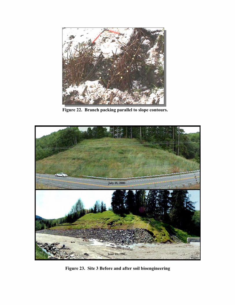
Figure 22. Branch packing parallel to slope contours.
Figure 23. Site 3 Before and after soil bioengineering

• Trend: improvement to stability.
• There was no evidence of mass movement or gully erosion.
• The site supported 95 percent vegetative cover.
• Brushlayer survivability:
brushlayer structures – 80 percent show new growth
willow wall structures – 40 percent show new growth.
• Survivability of vegetation on terraces:
uniform survival above rock apron – 70 percent overall
uniform survival within the rock apron – 40 percent overall.
Table 2 provides costs for the Lost Creek project.
Table 2. Lost Creek costs Item Cost Total WCC Crew Time (8 weeks) $20,000.00 Total Materials Cost $ 210.82 Vegetation Costs $ 1,131.64 Biosolid Application $ 3,200.00 RA Salary and Per Diem $ 3,712.00 Geotechnical Rock Apron $15,020.00 Total Cost for Project $30,774.46 Cost per Square Foot $ 3.55
RAYMOND
Construction on the Raymond project began January 31, 2000, and concluded
March 23, 2000. The original design was altered because underlying sheets of bedrock
failed when the toe was removed and left overnight without support. The principal
design change was the off-site construction of the log cribwalls and their installation as
modular 15-ft units. The slope was excavated in 15-ft sections, the cribwall units placed,
cribwall units cabled to the adjoining unit, willow stakes placed, and the cribwall
backfilled in approximately 2 hours per unit. This change allowed the project to continue

with minimum crew exposure to the unstable slope condition and with minimum time for
the undercut slope to strain without a stabilized toe.
The design also had to be changed because the delivered logs were larger than
those specified in the drawings. Rebar was used to link the logs instead of ¼-in. by 8-in.-
long spikes. Cables were used to link the cribwall sections that had been constructed off
site. Spaces between the logs were larger than originally designed and allowed for greater
soil exposure than was intended in the original design. The larger logs, however, did
result in the use of fewer logs.
The following are the results as of summer 2000.
• Trend: improvement to stability.
• There was no evidence of mass movement or surface erosion.
• The site supported 95 percent vegetative cover.
• Structure survivability:
cribwall structure - 90 percent new growth
willow wall structures – 30 percent show new growth
• fascines – 10 percent show new growth.
• Native woody vegetation survivability:
nursery stock – 80 percent survival
woody vegetation cuttings – 80 percent show new growth
no difference in survival between nursery stock and cuttings of the same species.
Table 3 summarizes the time and materials costs for the Raymond project:
Table 3. Raymond costs
Item Cost Total WCC Crew Time (10 weeks) $25,000.00Total Materials Costs $ 5,996.32 Heavy Equipment Rental $ 7,296.08 Vegetation Costs $ 1,820.00 RA’s Salary and Per Diem $ 4,212.00 SWR Costs $ 185.25

Total Cost for Project $44,509.65 Cost per Square Foot $ 1.59

COST/BENEFIT ANALYSIS1
PURPOSE
The benefit/cost analysis had the following objectives:
• assist decision-makers in justifying the promotion of soil bioengineering as a cost-saving and environmentally friendly alternative for surface erosion and shallow rapid landslide stabilization
• evaluate cost-efficiency and help select the best alternative from traditional engineering treatments, soil bioengineering, or their combinations
• educate WSDOT personnel, other land managers, and the public about the integration, economic efficiency, and environmental values of soil bioengineering.
Soil bioengineering as an alternative to roadside management offers, but is not
limited to, the following benefits:
• increased practicability
useful on sensitive or steep sites installed in construction slow seasons long-term soil stability
• cost savings
reduce/eliminate maintenance treat erosion earlier and avoid costly solutions use indigenous plant species
• improved environment
less soil disturbance to the site and adjoining areas improved air and water quality improved landscape and habitat values.
METHODOLOGY
Cost Assessment For the analysis, soil bioengineering treatment costs were the actual costs for
achieving the designed functions. Hypothetical traditional treatments costs were
1 Research analyst: George Xu, Ph.D. WSDOT Environmental Economist

estimated on the basis of phone interviews with WSDOT personnel. They were asked
what treatments would be used on the three sites if the department had chosen to treat
those slopes traditionally. Costs for those treatments were estimated by using the bid tabs
of nearby projects.
For the Chelan site, the traditional engineering treatment would have been to
excavate the slope back to a 1 ½(H) to 1(V) angle (Moses) and to apply a hydroseed mix
with tackifier to control surface erosion. (Tveten, Belmont, and Salisbury)
The traditional engineering treatment for Lost Creekwould have involved treating
surface water runoff by collecting runoff at the base of the slope in a quarry spall-lined
ditch, then moving it under the road in a culvert and into a detention pond to allow
sedimentation. (Witecki, Tveten, Salisbury) The fine, compacted soils on the site resisted
infiltration, and large amounts of overland flow contributed to sedimentation problems
during and after road construction. (Lewis) A rock apron was installed on this site to
prevent slope movement before the research project. Its cost was included in the
estimated cost for the non-soil bioengineering treatment.
For the Raymond site, the traditional engineering treatment would have been to
construct a rock buttress similar to one directly across the highway from the project
location. Note that typically, a soil stability analysis would be needed to determine the
size (mass) of a rock buttress. (Moses) Without this study, the size of the proposed
buttress was estimated the same volume as that of the constructed cribwall. Note also
that in this example, the purpose of the rock buttress was only to add a vertical
component to the slope by which the toe of the slope could be elevated to reduce overall
steepness and to provide support for eroding materials. A bench would have to be
excavated for placement of the rock buttress.
Benefit Assessment Soil bioengineering was evaluated as an alternative investment option in this
benefit cost analysis. Soil bioengineering projects were designed to produce the same
roadside stabilization effects as their traditional alternatives. Therefore, the cost saving
resulting from adoption of soil bioengineering projects was evaluated as a net benefit.

The benefit of stabilization was assessed by using the same cost pricing method for both
soil bioengineering and traditional alternatives.
Environmental benefits generated by the projects were assessed by using the
benefit transfer approach that is a common method in environmental economic
assessment when time and resources are limited. Environmental benefits were derived on
the basis of the results and findings of similar studies (Sotir 2001; EPA 1998, California
Department of Transportation 1998; McPherson & Simpson 1999), and transferred values
were adjusted according to the changes of key factors.
Trees remove pollutants from the atmosphere and also eliminate or reduce the
source of pollution. Pollutants deposited and particulates intercepted include ozone, NO2,
and PM10. Air pollutant uptake benefits were assessed on the basis of the number of trees
planted, growth rate and canopy cover information, unit value of pollutant uptake, and
effectiveness. Effectiveness was determined by evaluating source elimination and
pollutant uptake effects.
Stormwater runoff reduction benefits were assessed by using the runoff
coefficients of different land covers, the local hydrograph, sediment treatment
requirements, and the unit value of stormwater treated.
The assessment of carbon sequestration benefits was based on the assumption that
80 percent of carbon will be released at the end of the life cycle (removal of trees) and the
unit value of carbon sequestration derived by other studies.
Many other environmental and aesthetic values are associated with soil
bioengineering treatments. They were not assessed because of either intangibility or time
constraints.
Comparability Three key factors were considered to ensure the comparability of both benefits
and costs. They were effectiveness, life cycle, and discounting.
1. Effectiveness
The benefit of soil bioengineering alternatives should be adjusted in terms of
effectiveness. Soil bioengineering techniques are assumed to have the same effective as

traditional engineering methods when used on appropriate sites for roadside stabilization
and the treatment of runoff. However, since soil bioengineering uses living plants, it has
benefits that rock and cement do not have. For example, plants can provide air pollutant
uptake and carbon sequestration. Plants also provide visual benefits such as distraction
screening, guidance and navigation enhancement, and aesthetic pleasure. When we
applied benefit transfer to evaluate environmental benefits, the effectiveness for related
functions was assessed on the basis of the different conditions between the original study
sites and the sites of this study.
Table 4 shows the assumptions of effectiveness used in this study.
Table 4. Effectiveness assumptions
Effectiveness Assumptions Used in This Study
Roadside Stabilization Runoff Treatment Air Pollutant
Uptake CO2
Sequestration Chelan 100% 100% 34% 100%
Raymond 100%
Forks 100% 50% 9% 100%
Benefits for runoff treatment, air pollutant uptake, and CO2 sequestration for the
Raymond site are not shown. Because the slope was previously vegetated, those
functions were already taking place and no improvement was assumed.
Air pollutant uptake effectiveness for soil bioengineering treatments were
determined by two factors: seriousness of air pollution and air pollutant-taking capacity of
the alternative.
Data sources for the effectiveness analysis included Sotir (2001), EPA (1998),
California Department of Transportation (1998), and McPherson and Simpson (1999).

2. Life Cycle Analysis
Life cycle analysis was used to adjust the life cycle costs of both thetraditional and
soil bioengineering alternatives. The initial investment for a soil bioengineering project
can be higher than a traditional engineering technique, especially if no structure or heavy
riprap is involved. However, the project life is historically longer with a living system,
such as soil bioengineering. Therefor,e the annualized life cycle cost is lower with soil
bioengineering, since those systems can work at least 50 years. (Sotir 2001, Schiechtl
1980) Life cycle costs for soil bioengineering techniques were analyzed using a cycle of
30 years. A 20-year life cycle was used for traditional alternatives for roadside
management.
3. Discounting
Discounting was used to make benefit and cost streams over the project life
comparable. In other words, it made the benefits of different times comparable. The
discounting rate used in the analysis was 4 percent.
DATA SOURCES
The following were the major data sources used in this analysis:
• actual costs • estimated costs using historic data • Environmental Protection Agency (EPA) • USDA Forest Service • California Department of Transportation • experts’ opinions.
FINDINGS
Costs The costs for the three sites are summarized in the tables 5 and 6:
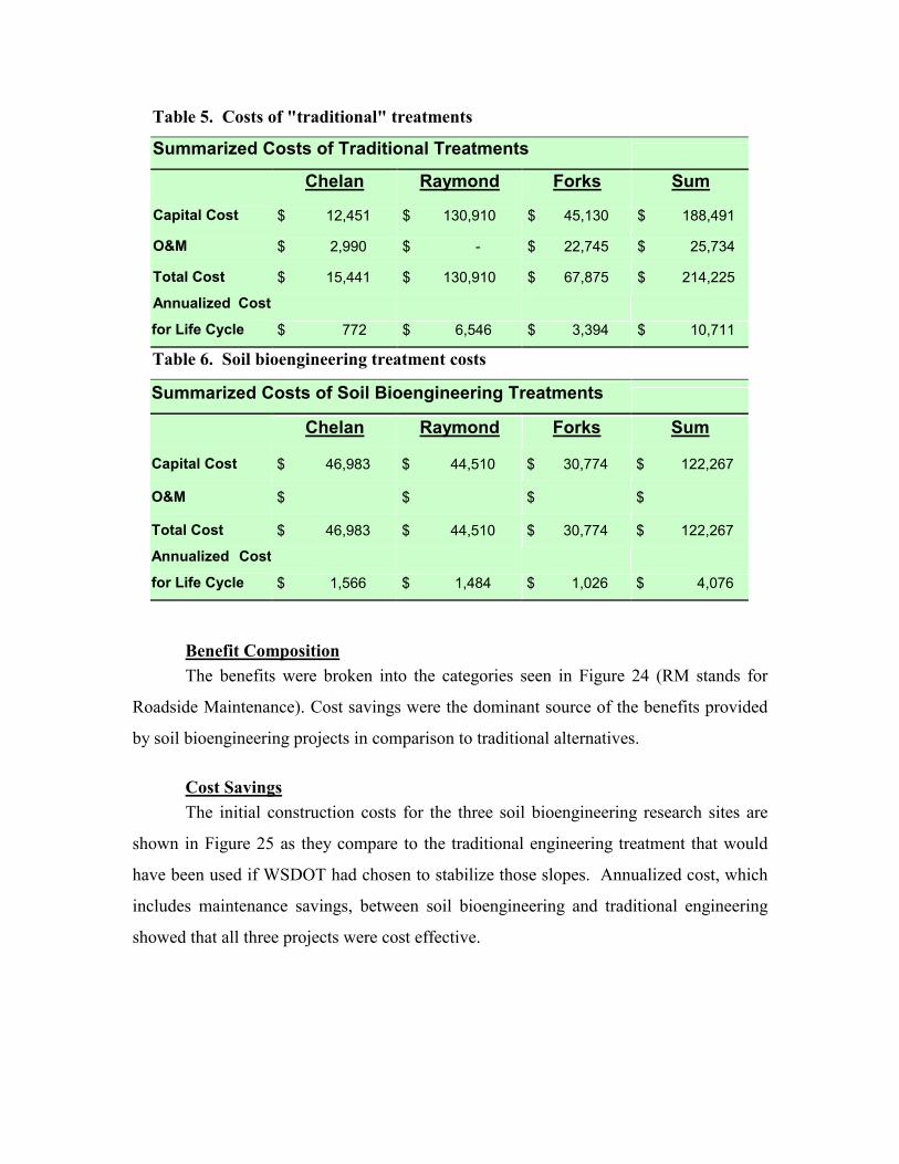
Table 5. Costs of "traditional" treatments
Summarized Costs of Traditional Treatments
Chelan Raymond Forks Sum
Capital Cost $ 12,451 $ 130,910 $ 45,130 $ 188,491
O&M $ 2,990 $ - $ 22,745 $ 25,734
Total Cost $ 15,441 $ 130,910 $ 67,875 $ 214,225
Annualized Cost
for Life Cycle $ 772 $ 6,546 $ 3,394 $ 10,711
Table 6. Soil bioengineering treatment costs
Summarized Costs of Soil Bioengineering Treatments
Chelan Raymond Forks Sum
Capital Cost $ 46,983 $ 44,510 $ 30,774 $ 122,267
O&M $ $ $ $
Total Cost $ 46,983 $ 44,510 $ 30,774 $ 122,267
Annualized Cost
for Life Cycle $ 1,566 $ 1,484 $ 1,026 $ 4,076
Benefit Composition The benefits were broken into the categories seen in Figure 24 (RM stands for
Roadside Maintenance). Cost savings were the dominant source of the benefits provided
by soil bioengineering projects in comparison to traditional alternatives.
Cost Savings The initial construction costs for the three soil bioengineering research sites are
shown in Figure 25 as they compare to the traditional engineering treatment that would
have been used if WSDOT had chosen to stabilize those slopes. Annualized cost, which
includes maintenance savings, between soil bioengineering and traditional engineering
showed that all three projects were cost effective.

RM Cost Saving63%
Runoff Control8%
Air Pollutant Uptake
24%
CO2 Sequestration
5%
Figure 24. Benefit composition
Cost Saving: Traditional Vs. Soil Bioengineering
$(1,000)
$1,000
$3,000
$5,000
$7,000
$9,000
$11,000
$13,000
Chelan Raymond Forks Sum
Traditional Alternative Soil Bioengineering Cost Saving
Figure 25. Initial construction cost saving

Benefits Table 7 summarizes the benefits of the soil bioengineering project.
Table 7. Assessed benefits of soil bioengineering alternatives
B/C Ratio The benefit to cost ratio is a means of comparing the dollar figure of benefits
derived in relation to the cost of a project. The benefit/cost figures include annualized
maintenance cost savings. For each dollar spent on the soil bioengineering projects, $1.44
benefit was generated at the Chelan site, $3 at the Raymond site and $2.78 at the Forks
site.
In comparison with the traditional treatments, for each dollar invested in roadside
stabilization using the soil bioengineering alternative, $1.01 more benefit was generated
than would have been with the traditional alternative ($2.41 – $1.40 = $1.01).
Assessed Benefits: Soil Bioengineering Alternatives
CHELAN RAYMOND FORKS
Life Cycle
Benefit
Annualized
Benefit
Life Cycle
Benefit
Annualized
Benefit
Life Cycle
Benefit
Annualized
Benefit
Total Benefit: $67,499 $2,250 $133,404 $4,447 $85,622 $2,854
Stabilization $15,441 $515 $133,404 $4,447 $67,872 $2,262
Runoff Control $1,638 $55 $13,338 $445
Air Pollutant Uptake $43,837 $1,461 $1,020 $34
CO2 Sequestration $6,583 $219 $3,391 $113
Total Costs: $46,983 $1,566 $44,510 $1,484 $30,774 $1,026
Net Benefit: $20,516 $684 $88,895 $2,963 $54,847 $1,828
B/C Ratio 1.44 1.44 3.00 3.00 2.78 2.78

Table 8. Benefit/cost ratio
B/C Ratio CHELAN RAYMOND FORKS Average
Soil Bioengineering 1.44 3.00 2.78 2.41
Traditional Alternative 1.95 1.00 1.26 1.40

CONCLUSIONS AND RECOMMENDATIONS
CONCLUSIONS
The following conclusions are based on experience acquired during the design and
construction phases of this project.
1. Soil bioengineering can be constructed and used successfully on WSDOT projects. As of the writing of this report, all three project sites are revegetating and appear stable. They demonstrate viable alternatives for stabilizing upland slopes.
2. When technically feasible, soil bioengineering alternatives can be adopted to produce equal or better economic and environmental results than the traditional geotechnical solutions alone. The average benefit to cost ratio in this study was 2.41, demonstrating that soil bioengineering is a favorable economic alternative in roadside management.
3. Incorporated (“raked in”) composted Class A biosolids used on the Chelan site correlated with enhanced grass growth. The addition of composted Class A biosolids increased soil workability and influenced the grass community composition.
4. On project areas with a potential for mass wasting, such as sections of both the Lost Creek and Raymond sites, an engineering slope stability analysis should be performed. This was done on the Lost Creek site.
5. Woody vegetation planted as 10-inch plugs had a higher survival rate than the bare root plants at the Chelan site. Purchasing plugs or containerized plants in Central and Eastern Washington may increase survival rates.
6. The creation of terraces at the Chelan site allowed for enhanced plant growth. Little vegetation is now growing on the steep areas between the terraces. This is similar to the on-site conditions before the project. While the initial costs of soil bioengineering are higher than the costs of slope flattening and hydroseeding (the “traditional” approach), more vegetation establishes with soil bioengineering. This allows for more long-term environmental benefits, such as air and water quality improvements.
7. Communication and education are important components of any “new” technology.
8. An interdisciplinary team, continuously involved in the project, is critical for success.

RECOMMENDATIONS
• Further monitoring is recommended to analyze the long-term stability of these slopes. This monitoring must include observations by local maintenance personnel and will be carried out by the Olympia Service Center Roadside and Site Development Office.
• Composted biosolids created with a carbon-to-nitrogen ratio formula can be applied on other projects to reduce weed competition, reduce soil erosion, and enhance native plant growth. It is critical to incorporate (rake in) these biosolids as they are applied.
• The long-term survival and vigor of plants in the control and composted biosolids areas of the Chelan site should be studied to determine the residual benefits of biosolids application.
• Further research into the cost/benefit ratio of soil bioengineering techniques should be carried out in areas with other climates and soils.
• Research projects should have one project manager. That person, preferably the PI, should be in charge of authorizing all expenses and tracking the budget. The PI should do a thorough cost estimate before beginning work. Additional dollars should be budgeted for contingencies.
• Further study is needed to analyze the shear stress of different plant root masses under varying slope angles, moisture conditions, and soil types. Currently, this type of research is under way in the United Kingdom. Results of that work can be found at http://www.highways.gov.uk/info/techinf/randd/compen/8a.htm#1
• This type of work should be translated to local ecosystems (soils and plant types).
• Persons or agencies wishing to use this technology should do so with a team of experts and should begin with small erosional features on small slopes before working on large slopes.
• The plants and soil bioengineering techniques used must be specific to each site.
LIMITATIONS OF THE STUDY
• Project funding was limited to deal with the extent of the unexpected problems encountered at each site. In addition, all three sites were large and complicated, and funding levels limited the scope of the numerous soil bioengineering techniques the team could have used to stabilize the sites.
• The benefit-cost study was limited by funding and time. Further study into the benefit/cost ratios of soil bioengineering methods in varying ecosystems is needed, especially for Eastern Washington.

• When changes were necessary, it was difficult for the PI, because of her location in Oregon, to be physically present. However, the use of digital cameras, digital photographs, and frequent conference calls kept the project moving forward without interruption.
OUTCOMES
The following outcomes were directly associated with this project:
• Three large upland slope stabilization projects were constructed.
• The research report was published on the OSC Roadside and Site Development Unit
Internet homepage at http://www.wsdot.wa.gov/eesc/cae/design/roadside/rm.htm.
• WSDOT personnel were trained in the selection of soil bioengineering sites and in the
design and construction of soil bioengineering techniques.
• The Federal Highway Administration contracted the OSC Roadside and Site
Development Unit to analyze slopes in southwestern Oregon for the possible design
of soil bioengineering treatments.
• Regional offices within WSDOT have shown an interest in using soil bioengineering
on specific roadside sites.
• A chapter on soil bioengineering has been written for the department’s Roadside
Manual.
• A workshop was conducted by the Principal Investigator and the research team for
WSDOT personnel.
• WSDOT obtained the right to use and reproduce all materials from Lewis, E.A., Soil
Bioengineering: An Alternative for Roadside Management: A Practical Guide. United
States Forest Service. San Dimas Technology and Development Center. San Dimas,
California, 2000.
• The value of using soil amendments to enhance plant survival was demonstrated.
• Communication skills, for example use of interdisciplinary team process, were
highlighted and enhanced.
• Project management skills were highlighted and awareness enhanced.
• Partnerships were formed that will carry into the future.
• Awareness of soil bioengineering as an option for roadside stabilization and erosion

control was increased within WSDOT.
• Relations with the public were enhanced by the publication of four articles (two local
newspapers, an in-house newsletter, and a nationally distributed magazine) about
WSDOT’s use of a natural method of erosion control.

ACKNOWLEDGMENTS
The authors express their appreciation to the personnel of the Washington State
Department of Transportation who provided information and help with all the various
aspects of this project. Special thanks go to the USDA Forest Service for funding of the
Principal Investigator’s time and travel and to the Entiat Ranger Station for its logistical
support. The authors would like to recognize the contribution of the Washington State
Department of Ecology’s donation of Washington Conservation Crew time to this project.
The authors gratefully acknowledge the support of WSDOT’s Research Office, the
Environmental and Engineering Service Center, and the Field Operations Service and
Support Center. The author’s wish to thank Dr. George Xu for his work on the
benefit/cost analysis.
The Chelan project would not have been possible without the granting of a
construction easement by the adjacent landowners, Art and Susan Douglas. The authors
are very grateful for their contribution to this project. Mark Cullington, formerly of the
Department of Ecology, provided guidance and calculations for the application of
composted biosolids, and we are most grateful for his contributions. Thanks go to
McCully Orchards for providing apple stakes for the Chelan project. The authors
appreciate the research of Kevin Finney on the history of soil bioengineering.
The authors wish to thank the City of Raymond and the Willapa Port Authority
for allowing us to take willow cuttings from their lands for the Raymond project. The
authors wish to thank the Rayonier Timber company for allowing us to taking willow
cuttings from their land for the Forks project. We appreciate the help of the Jefferson
County Extension Service, the Natural Resource Conservation Service, and the National
Park Service for their help with plant selections adaptable to marine clay. We appreciate
the opportunity to coordinate with the Hoh Tribe on the Forks project. Finally, this
project could not have been completed without the active participation of maintenance
personnel in the North Central, Olympic, and Southwest regions.

BIBLIOGRAPHY
SOIL BIOENGINEERING METHODS
Bache, D. H. and I. A. MacAskill. Vegetation in Civil and Landscape Engineering. London: Granada. 1984.
Barker, D. H. editor. Vegetation and slopes: Stabilization, protection, and ecology. New York: Thomas Telford Publishing Company. 1995.
Bennett, Francis W. “Methods of Quickly Vegetating Soils of Low Productivity.” Construction Activities. Washington, D.C.: U.S. Environmental Protection Agency. 1975.
Chandler, R. J. Slope Stability Engineering. Institution of Civil Engineers. New York: Thomas Telford Publishing Company. 1991.
Chatwin, S., D. Howes, and D. Swantson. A Guide for Management of Landslide Prone Terrain in the Pacific Northwest. Second edition. Ministry of Forests. Victoria, BC: Crown Publications. 1994.
Christensen, M. and J. Jacobovitch. Revegetation Projects: Everything You Wanted to Know About Live Staking. Unpublished report for King County Dept. of Public Works, Surface Water Management Div. Seattle, WA. 1992.
Coppin, N. J. and I.G. Richards. Use of Vegetation in Civil Engineering. London: Butterworths. 1990.
Finney, Kevin P. BioEngineering Solutions, A Tool for Education. Submitted in partial fulfillment of the degree of Master of Landscape Architecture, University of Oregon. 1993.
Gray, Donald H. and Robbin B. Sotir. Biotechnical and Soil Bioengineering Slope Stabilization: A Practical Guide for Erosion Control. New York: John Wiley & Sons, Inc. 1996.
Donald H. Gray and Andrew T. Leiser. Biotechnical Slope Protection and Erosion Control. New York: VanNostrand Reinhold Co. 1982.
Gray, Donald H., Andrew T. Leiser, and C. A. White. “Combined Vegetative Structural Slope Stabilization. Civil Engineering, 50(1) January 1980: pp. 82-85.
Greenway, D.R. “Vegetation and Slope Stability - Chapter 6.” Slope Stability. John Wiley and Sons Ltd. 1987.
Johnson, A.W. and J.M. Stypula. eds. Guidelines for Bank Stabilization Projects In the Riverine Environments of King County. King County Department of Public Works, Surface Water Management Division, Seattle, WA. 1993.
Kraebel, C.J. Willow Cuttings for Erosion Control. Technical Note No. 1, USDA, California Forest Experiment Station, Berkeley, California. 1933.
------Erosion Control on Mountain Roads, U.S.D.A. Circular No. 380, USDA,

Washington D.C. 1936.
Larson, F.E. and W.E. Guse. Propagating Deciduous and Evergreen Shrubs, Trees, and Vines with Stem Cuttings. Pacific Northwest Coop. Ext. Pub. PNW152. 1981.
Leiser, Andrew T., J.J. Nussbaum, Kay, Burgess, Paul, Jack, and W. Thornhill. Revegetation of Disturbed Soils in the Tahoe Basin. Final Report: CA-DOT-TL-7036-1-75-25. California Department of Transportation, Sacramento, California. 1974.
Lewis, E.A. Soil Bioengineering: An alternative for Roadside Management: A Practical Guide. United States Forest Service. San Dimas Technology and Development Center. San Dimas, California. 2000.
Maleike, R. and R.L. Hummel. Planting Landscape Plants. Washington State University Cooperative Extension Publication EB1505. 1988.
David F, Polster. “Soil Bioengineering for Steep/Unstable Slopes and Riparian Restoration.” Watershed Restoration Technical Bulletin: Streamline. Victoria, British Columbia: B.C. Ministry of Environment. Vol. 4, No. 4.
..... Soil Bioengineering for Forest Land Reclamation and Stabilization. British Columbia Ministry of Forests. 1998.
Schiechtl, Hugo and R. Stern. Ground Bioengineering Techniques for Slope Protection and Erosion Control. Blackwell Science Publications, 1997. ISBN: 0-632-04061-0
Schiechtl, Hugo. Bioengineering for Land Reclamation and Conservation. Edmonton: University of Alberta Press. 1980.
State of Alaska website on streambank stabilization http://www.state.ak.us/adfg/habitat/geninfo/webpage/techniques.htm
Turner & Schuster, eds. Landslides Investigation and Mitigation, Special Report, Transportation Research Board. 1996.
U.S. Army Corps of Engineers. Bioengineering for Streambank Erosion Control - Report 1, Guidelines. Technical Report EL-97-8. Can be found through the following link: http://www.wes.army.mil/el/wetlands/wlpubs.html
USDA Natural Resource Conservation Service. Chapter 16, “Streambank and Shoreline Protection,” Engineering Field Handbook. United States Department of Agriculture, 1996.
USDA Natural Resource Conservation Service. Chapter 18, “Soil Bioengineering for Upland Slope Protection and Erosion Reduction,” Engineering Field Handbook. United States Department of Agriculture, 1992.
Weaver, W.E. and M.A. Madej. “Erosion Control Techniques Used in Redwood National Park.” In: T.R.H. Davies and A.J. Pearce, eds. Erosion and Sediment Transport in Pacific Rim Steeplands. Washington D.C. Int'l Assoc. Hydrological Sciences: 640-654. IAHS-AISH Pub. 132. 1981.

Westmacott, Richard. “The Rediscovered Arts of Twilling and Wattling.” Landscape Architecture. 75(4): 95-98. 1985.
White, Charles A. and A.L. Franks. Demonstration of Erosion and Sediment Control Technology; Lake Tahoe Region of California, EPA-600/2-78-208, Municipal Environmental Research Laboratory, Office of Research and Development, US Environmental Protection Agency, Cincinnati, Ohio. 1978.
Ziemer, R.R. “Roots and the Stability of Forested Slopes.” In: T.R.H. Davies and A.J. Pearce, eds. Erosion and Sediment Transport in Pacific Rim Steeplands. 1981.
BENEFIT/COST ANALYSIS
California Department of Transportation. 1998. Cost of Stormwater Treatment for California Urbanized Areas.
EPA. 1999. Economic Analysis of the Final Phase II Stormwater Rule. Office of Water. EPA 833-R-99-002.
E. Gregory McPherson and James R. Simpson. Carbon Dioxide Reduction Through Urban Forestry: Guidelines for Professional and Volunteer Tree Planters. Berkeley, California. USDA Forest Service. 1999.
Robbin Sotir. Phone conversation. January 2001.
http://wcufre.ucdavis.edu/benefit-.htm
SOIL BIOENGINEERING HISTORY
Brosius, Myra. “The Restoration of an Urban Stream Using Geomorphic Relationships and Biotechnical Streambank Stabilization.” MLA Thesis, University of Georgia. 1985.
Coppin, Nick J. and R. Stiles. “The Use of Vegetation in Slope Stabilization.” Landscape Design with Plants. Second Edition, ed. by Brian Clouston. Boca Raton, Florida: CRC Press. pp. 212-234. 1989.
Edlin, H.L. Woodland Crafts in Britain. London: B.T. Batsford Ltd. 1949.
Finney, K. History of Soil Bioengineering. Masters Thesis, University of Oregon. 1993.
Leys, Emil. “Wilhelm Hassenteufel 80 Years Old.” Garten und Landschaft in China. Vol. 4, Part 3. Cambridge: The University Press. 1978.
Schiechtl, Hugo. Bioengineering for Land Reclamation and Conservation. Edmonton, Canada: The University of Alberta Press. 1980.
Sotir, Robbin B. &Associates, A Brief History of Soil Bioengineering, unpublished and undated manuscript.
Stiles, Richard. “Engineering with Vegetation.” Landscape Design. (172): 57-61. 1988.
------ “Re-inventing the Wheel?” Landscape Design. (203): 1991.

Westmacott, Richard. “The Rediscovered Arts of Twilling and Wattling.” Landscape Architecture. 75(4): 95-98. 1985.

A-1
APPENDIX A: PROJECT PARTICIPANTS
Team Member Role Representing
Lisa Lewis Team Leader & Principal Investigator
USDA Forest Service
Shannon Hagen Research Assistant WSDOT
Jim Schafer Research Coordinator WSDOT, Environmental Affairs Office
Mark Maurer, L.A. Technical Support WSDOT, OSC Roadside and Site Development Manager
Bob Barnes, L.A. Technical Support WSDOT, Olympic Region Landscape Architect
Lynn Moses Technical Support WSDOT, Materials Lab. Engineering Geologist
Sandy Salisbury Technical Support, compiled this report
WSDOT, OSC Roadside and Site Development
Terri Dukes Technical Support, Lost Creek site
WSDOT, Olympic Region Landscape Architecture
Carrie Sunstrom Technical Support, wrote original grant application
WSDOT, Olympic Region Landscape Architecture
Ed Winkley Technical Support, Lost Creek site
WSDOT, Olympic Region Landscape Architecture
Dan Corlett, L.A. Technical Support, Raymond site
WSDOT, Southwest Region Landscape Architecture
Mike Whipple Raymond site excavation & construction
WSDOT, Raymond Maintenance Supervisor

A-2
Team Member Role Representing
Sally Anderson, L.A. Technical Support WSDOT, Northwest Region Principal Landscape Architect
Ray Willard, L.A. Technical Support WSDOT, OSC Roadside Maintenance Landscape Architect.
Russ Rosenthal, PhD Technical Support WSDOT, State Horticulturist
Dave Rodin, L.A. Technical Support, Raymond
WSDOT, Southwest Region Landscape Architectect
Claton Belmont Technical Support, Chelan
WSDOT, North Central Region Environmental Manager
Jim Flack Technical Support, Chelan
WSDOT, North Central Region Environmental Office
DeWayne Standerford
Technical Support, Chelan
WSDOT, North Central Region Maintenance Superintendent
Darrel Anderson Technical Support, Chelan
WSDOT, North Central Region, Chelan Area Maintenance Supervisor
Dick Albin Technical Support WSDOT, OSC Design Office, Standards Engineer

B-1
APPENDIX B: DEFINITIONS
angle of repose the angle between the horizontal and the maximum slope that a soil assumes through natural processes.2
Approximate Angle of Repose for Soil Texture
Very wet clay and silt 1V:3H
Wet clay and silt 1V:2H
Dry sand and gravel 1V:1¾
Dry clay 1V:1½
Moist sand 1V:1¼
ecosystem a complex of biological communities and the physical and chemical
environment forming a functioning whole in nature. Wetlands, upland forests, lakes, and streams are examples of types of ecosystems.3
physiographic a geographic unit with discrete physical characteristics, such as elevation, aspect, and rainfall patterns.
rotational failure a slide that moves along a surface of rupture that is curved and concave.4
slope gradient the angle of the slope as expressed in a percentage.
soil bioengineering the use of live plant materials and engineering techniques to reinforce soil and stabilize slopes.
translational failure a slide mass that displaces along a planar or undulating surface of rupture and slides out over the original ground surface. Translational slides frequently grade into flows or spreads.
2 Robert W. Zolomij. “Vehicular Circulation.” Handbook of Landscape Architecture Construction. 1975. p. 66. 3 Transportation Research Board. “Report 379: Guidelines for the Development of Wetland Replacement Areas.
Washington D.C.. National Academy Press. 1996. p. 72. 4 Turner & Schuster, eds, 1996, Landslides Investigation and Mitigation, Special Report, Transportation Research
Board, pp. 56-57.

B-2

C-1
APPENDIX C: LITERATURE REVIEW
Much like the practices of medicine, engineering, and architecture, soil
bioengineering developed historically as discrete techniques designed to solve specific
problems. Knowledge of these techniques was part of the body of folk wisdom
accumulated long ago and passed orally from generation to generation. In the last two
centuries, this knowledge has been compiled and codified, and finally in fairly recent
times, has been taught formally and practiced as a profession.
The system of technologies that is called soil bioengineering today can be traced
to the ancient peoples of Asia and Europe. Chinese historians recorded use of soil
bioengineering techniques for dike repair as early as 28 BC. (Needham, 1971, p. 331)
Early visitors to China told of river banks and dikes stabilized with large baskets woven
of willow, hemp, or bamboo and filled with rocks. In Europe, Celtic and Illyrian villagers
developed techniques of weaving willow branches together to create fences and walls.
Later, Romans used fascines, bundles of willow poles, for hydroconstruction.
By the 16th century, soil bioengineering techniques were being used and codified
throughout Europe, from the Alps to the Baltic Sea and west to the British Isles. One of
the earliest surviving written accounts of the use of soil bioengineering techniques, a
publication by Woltmann from 1791, illustrated the use of live stakes for vegetating and
stabilizing stream banks. (Stiles, 1991, p.ii) About the same time, other early
bioengineers working in Austria were developing live siltation construction techniques,
planting rows of brushy cuttings in waterways for trapping sediment and reshaping
channels.
After the Industrial Revolution, much of the development and documentation of
soil bioengineering techniques took place in the mountainous areas of Austria and
southern Germany. Extensive logging of the forests in the region resulted in increased
environmental problems, much like what is found in parts of the western U.S. today.
Problems such as extreme slope erosion, frequent landslides and avalanches, and severe
stream bank degradation required repair. By the turn of the century, European

C-2
bioengineers had begun to study traditional techniques and to publish their work. Today’s
soil bioengineering profession would develop from these compilations.
The biggest boost to development of new soil bioengineering techniques in
Europe came as a result of political developments during the 1930s. Financial restrictions
of pre-war years in Germany and Austria favored the use of low cost, local materials and
traditional construction methods for public works projects. Construction of the German
Autobahn system, during this time, involved extensive applications of soil bioengineering
technologies. The use of indigenous materials and traditional methods was also
consistent with spreading nationalist ideology. In 1936, Hitler established a research
institute in Munich charged with developing soil bioengineering techniques for road
construction. (Stiles, 1988, p. 59) Although this development work was lost, a Livonian
forester named Arthur von Kruedener, the head of the institute, continued to work in the
field and is known in central Europe as the father of soil bioengineering.
At the same time the Germans were establishing their research institute, some of
the most important early soil bioengineering work in the United States was being done in
California. Charles Kraebel, working for the US Forest Service, was developing his
“contour wattling” techniques for stabilizing road cuts. Kraebel used a combination of
soil bioengineering techniques including live stakes, live fascines, and vegetative
transplants to stabilize degrading slopes in the National Forests of central and southern
California. His unfortunate and confusing misuse of the term “wattle” to describe his live
fascine system continues to be used today. Kraebel’s work was well documented in
USDA Circular #380, published in 1936. Two years later the Natural Resource
Conservation Service (NRCS), formally known as the Soil Conservation Service, began a
study of bluff stabilization techniques along the shores of Lake Michigan. That agency’s
work, which included use of live fascines, brush dams, and live stakes, was published in
1938. (Gray and Leiser, 1982, p. 188)
During the post-war period, many European bioengineers returned to studying,
developing, and evaluating new techniques. In 1950, a committee of bioengineers from
Germany, Austria, and Switzerland was formed to standardize emerging technologies,

C-3
which became part of the German national system of construction specifications, the DIN.
(Robbin B. Sotir & Associates, n.d.)
Arthor von Kruedener’s book, Ingenieurbiologie (Engineering biology), was
published in 1951, and it was the mistranslation of the German title that provided the
English term used today. The term “bioengineering” has caused some confusion and has
proven problematic for researchers, who find, in this country, that it is most often thought
to refer to an area of medical research.
German and Austrian soil bioengineers continued to perfect their techniques and
to publish their work through the 1950s and ‘60s. This was an important step in
launching a more structural approach, laying the foundation for development of the
professional field of soil bioengineering. In the United States, two important projects
were carried out in the 1970s. These are the Trials of Bioengineering Techniques in the
Lake Tahoe Basin designed by Leiser and others (1974), and Revegetation Work in
Redwood National Park (Reed and Hektner, 1981, Weaver,et al., 1987). Both studies
have been well documented and provide important information about the application of
soil bioengineering techniques in the western United States.
In 1980, Hugo Schiechtl’s Bioengineering for Land Reclamation and
Conservation was published in Canada. It presents, for the first time in English, work of
many important European soil bioengineers, including Lorenz, Hassenteufel, Hoffman,
Courtorier, and Schiechtl himself. The book made the technologies and the history of
their development and applications accessible to the English speaking world. In 1997,
another Schiechtl book was published, Ground Bioengineering Techniques for Slope
Protection and Erosion Control. To date, his writings remain the most important works
on bioengineering in the English language.
With subsequent publications, including Gray and Leiser’s Biotechnical Slope
Protection and Erosion Control in the United States and the British Construction Industry
Research, Sotir and Gray’s Soil Bioengineering for Upland Slope Protection and Erosion
Reduction in the Natural Resource and Conservation Service’s Engineering Field
Handbook, Gray and Sotir’s Biotechnical and Soil Bioengineering Slope Stabilization,
and the Information Association’s Use of Vegetation in Civil Engineering, bioengineering

C-4
technologies are better known in the engineering profession. However, resistance to the
techniques still exists in this country.
Soil bioengineering approaches most often use locally available materials and a
minimum of heavy equipment and can offer local people an inexpensive way to resolve
local environmental problems. The public’s increased “green” consciousness often
makes soil bioengineering solutions more acceptable than traditional engineering
approaches.
Despite, and maybe because of, the differences in approach and philosophy
between soil bioengineering and other engineering methods of addressing environmental
problems, soil bioengineering technologies are especially appropriate today. The scale
and range of environmental problems require consideration of new technologies even
when, as illustrated earlier, they are in fact centuries old.

D-1
APPENDIX D: CHECKLIST FOR EVALUATING EROSION SITES
Name of Erosion Site: Date: Road Number or Name: Milepost Number: Name of Observer(s):
Yes No N/A
1. Overland water flow is not contributing to accelerated erosion (i.e., formation of rills and gullies)
2. Upland watershed is not contributing to site degradation
3. Diverse composition of vegetation
4. Site is comprised of those plants, or plant communities, with root masses capable of preventing further erosion
5. Plants exhibit high vigor
6. Adequate vegetative cover present to protect slopes and dissipate overland water flow
7. Erosion site is revegetating with native vegetation
8. Erosion site shows no sign of additional soil movement
9. Ditch line has no evidence of fresh soil deposits

D-2
Remarks
Summary Determination
Stabilization Rating: Stable Stability - At risk Not Stable Unknown Trend for Stability - At Risk: Upward Downward Not Apparent Photograph or Sketch

E-1
APPENDIX E: MONITORING FORM
Soil Bioengineering Project
Date: Preparer(s): Site Name: SR Road Mp: Geographic Features Elevation: Slope% Aspect: Soils: Erosion Source: Shade (H-M-L): Dimensions: L x W x D Ground Cover: %Vegetation %Soil %Rock Vegetation Information
Trees Shrubs
Evergrn Decid Evergrn Decid
Herbaceous
Grasses
Species Noted: Noxious Weeds: Treatment Information Treatment Date` Description Success/Vigor (H-M-L) Overall Condition Current Condition: Improving No Change Worsening

E-2
Narrative
High Priority Low Priority Not Needed Maintenance Needed? Site Sketch
(Please include groundcover, structures, plants and any erosion evidence)
F-1
APPENDIX F
METHODS: FURTHER DETAILS
SITE SELECTION
WSDOT Engineering Geologists, in the Olympia Service Center (OSC) Materials
Laboratory, keep a record of erosional slopes. These data were provided to the Research
Team. The eastern half of the state was not considered for this project because the team
wanted slopes closer to Olympia for easier logistics in construction and monitoring.
E-mails were sent in March 1999 to four of the regional Materials Engineers
(Olympic, Southwest, North Central, South Central) to seek their help in locating
erosional slopes within quarry and pit sites, or on the highway. They were also asked
whether any maintenance areas had erosional slopes that might be included in this
project. At this time the PI thought that 50 bioengineering sites might be available
statewide for use in the research project, if they all were less than ¼ acre in size and had
erosional features. The slopes identified by the regional Materials Engineers and
Maintenance personnel were compiled into a list of potential sites. Some slopes were
also nominated by the Olympic Region LA.
On June 15, 1999, the PI and members of the research team made site visits to
problem slopes along over 350 miles of Highway 101 around the Olympic Peninsula.
The special stops included three major landslides on SR 101 (MP 321, MP 322, and MP
326) that were clearly not soil bioengineering candidates for this project
From June 16 through June 18, 1999, the PI and research team members traveled
over 1,500 miles to evaluate additional sites suggested by the regional Materials
Engineers. See Figure F-1 for site visit routes:

F-2
Figure F-5. Screening Site Visit Route
From June 16 through 18, 1999, the team reviewed 82 sites, analyzing their
potential use. Later in June the PI made additional site visits to slopes on SR 101, SR 14,
and SR 3 to view sites requested by Maintenance. The following criteria were used to
select three sites from those candidates.
Site Selection Criteria The PI took comments from all team members on site selection, but the final
decision was hers. She wanted a combination of fill slope and cut slope erosional
features represented in the research project. However, no fill slope areas met all the site
selection criteria. The criteria for selection were as follows:
• safety of the public and work crews (road and slope related safety issues were addressed)
• visibility and accessibility for educational opportunities
• representation of the disparate soil moisture conditions, climate, and erosion types common to Washington State
• illustration of techniques that could be used on large erosion sites, small erosion sites, and combined soil bioengineering and traditional engineering treatments
• allocated dollars and the availability of additional funding
June 15
June 16-18

F-3
• input from WSDOT personnel.
Sites Selected The team had originally intended to work on several smaller sites; however,
because of the difficulty of working on so many sites over long distances in a limited
time, the PI decided to use several techniques on each of the selected sites. Three sites
were selected: two west-side sites and one site east of the Cascade Mountains. Two of
the sites, Raymond and Chelan, are considered large sites. Because of the many storm
damaged slopes in the state, the Engineering Geologists and Geotechnical Engineers were
too busy to do a special project combining soil bioengineering with a traditional
treatment. The Lost Creek site, near Forks, was selected because it had a rock apron at
the base.
CHELAN
Bender Board Fence Specifications
Tools needed
Hand pruners and clippers
Pulaski or hazel hoe
McLeod rake
Deadblow or rubber hammer
Pickaxe
Wood stakes
Stem-Layered Base
Begin the project at the base of the treatment area. Excavate a 24-in.-deep terrace
along the slope contour and for the full width of the treatment area. The back of the
terrace should be dug at an approximate 70-degree angle. To allow ample planting
platforms, space terraces about 5 ft apart.
Lay 2 ft 6 in.-long stems and 2 ft 6 in.-long wood stakes (50/50 mix) 2 inches
apart and for the full length of the terrace. The diameter can range from ½ in. to 2 in.

F-4
Approximately 6 in. will extend beyond the slope face. Every 1 ft, place plant material
(plugs) within the terrace.
Bender Board Fencing Construction
Drive supporting 4 ft 6 in.-long (2 ft x 2 ft) stakes 2 ft 3 in. into the ground
vertically, and spaced 2 ft apart.
Weave 10-ft-long bender boards through these stakes until the wall reaches a
height of 2 ft. Once complete, the bender board fence wall should be at a 15-degree angle
to the slope. Once the wall frame has been constructed, carefully rake enough soil into
the terrace to cover the stem layered base.
Stand in the terrace and begin excavation of a second row. This process will
allow soil from the second trench to cover the first bender board fencing row.
A goal should be to construct a 2:1 slope, or flatter, between the top of the bender
board fence wall and the bottom of the one above.
Move upslope to the next terrace alignment and repeat the process.
Plant trees and shrubs on the terraces. For this project, the species mix was
selected by the PI, research assistant, and WSDOT Landscape Architects. The location of
installation was determined by the RA and Landscape Architect(s) at WSDOT. The PI
reviewed the work to make sure placement met slope stability objectives.
Problems and Solutions During Construction The contractor began working on Monday, November 1, 1999. His crew removed
approximately 14 trees near the right-of-way line and then attempted to remove the
vertical lip of the slope from above. Because of the large amount of volcanic ash and
glacial materials, the top soil layer was soft and difficult to excavate. As a result, the
front-end loader left deep track marks and began slipping near the slope edge and had to
be pulled out by an excavator. The soil disturbance on their property upset the
landowners. As a result, the contractor removed his machinery and began working from
the base of the slope with an excavator.
Soil below the soft, top layer was composed of compacted glacial materials.
These compacted materials were hard and required the contractor to use a bucket with

F-5
teeth to scrape at the “rock-like” material. These conditions lengthened the excavation
time beyond the anticipated three to four days.
The Washington Conservation Crew (WCC, hereinafter referred to as “the crew”)
arrived on Thursday afternoon, November 4, 1999, while the heavy equipment contractor
was still working. However, the contractor had finished excavation on the west end of
the site by that time. The crew spent Thursday setting up their materials. The research
assistant (RA) used a laser level to stake level terraces. Beginning from the west, the crew
began digging out the terraces with great difficulty. In addition, the crew could not start
from the bottom of the slope because the excavator was working there. Therefore, they
began with one of the middle terraces, working from the west end of the site. Because of
the hardness of the soil, terrace construction took much more time than anticipated. Once
the soil was broken up, however, it became a fine powder mixed with sand and rounded
rocks. This mix of soil materials made walking on the slope difficult.
As the RA and the crew began trying to construct the bender board fencing as
designed, they discovered they could not get the specified wooden stakes into the ground.
The RA decided to try ½-in.-diameter rebar and to use the wood stakes as the brush layer
base. In addition, the bender board material was much thinner and weaker than
anticipated. This necessitated a change in the design. Plant plugs had been heeled-in
within the right-of-way and were now frozen. To plant the plugs, the crew chief thawed
the plugs and set them between the brush layer every 3 ft, where they froze again.
When the WSDOT Landscape Designer, hereinafter referred to as the Landscape
Designer, arrived on Sunday, November 7, 1999, approximately 110 ft of bender board
terrace, seven boards high, had been constructed, and approximately two-thirds of the
slope had been excavated back to 1 ½ (H):1 (V).
On Monday, the heavy equipment contractor returned to finish the excavation on
the eastern end of the site, and the crew continued constructing the level terrace. The
Landscape Designer had the crew leave the terrace and had the excavator operator
backfill the terrace with excavated material. The operator was very careful and worked to
shake out boulders before he placed the soil behind the bender board fencing.
Immediately after backfilling, the terrace looked good. However, three hours later

F-6
sections of the terrace had warped out of alignment in a slow deformation. The
Landscape Designer had the crew remove the soil down to a depth of less than 1 ft in an
attempt to halt the bending of the rebar and the breaking of the bender board material.
The crew also began repairing the damaged area, including the landowner’s property.
Repair work included raking, seeding, and planting.
The following species were planted on the landowner’s property:
Service berry (Amelanchier alnifolia) 10
Snow berry (Symphoricarpos albus) 20
Blue Elderberry (Sambucus cerulea) 5
Mock Orange (Philidelphus lewisii) 5
Ponderosa Pine (Pinus ponderosa) 50
Squaw currant (Ribes cereum)
10
Native seed mix 10lbs
Even after attempting repairs on the bender board fence, the crew could still feel
the brush layer on the base of the terrace moving and hear bender boards cracking. The
crew leader did not feel that ½-in. rebar had enough strength to be driven into the soil
without bending. The Landscape Designer consulted with the PI by phone, and a decision
was made to halt crew work on the site at the end of the day on Monday, pending a site
visit by the PI and WSDOT technical advisors. The Landscape Designer was also
concerned by the large amount of rebar going into a soil bioengineering project.
The Contractor completed excavation of the slope face by noon on Tuesday,
November 9th.
Further hand construction was delayed until after the first week in December,
when the PI, the OSC Roadside and Site Development Manager, and Department of
Ecology Soil Scientist Mark Cullington could examine the slope conditions. They made
the on-site decision to continue using rebar to reinforce the terraces and to adjust bender
board structures from 2 ft to a 1 ft height (three boards instead of six).
Construction resumed with a different crew in mid-December. The RA and the
crew made an additional decision to discontinue weaving the bender board through the
rebar because the bender board was breaking. The poor quality bender board was thin

F-7
and had many knots. In addition, the gaps in the fencing, created by the weave, allowed
soil to erode out from the bender board face. Instead, they had the soil hold the boards
against the rebar. This adjustment also held the soil in place.
The Landscape Designer checked the site on March 15, 2000, to determine
whether the soil had thawed and to check for disturbance to the site during winter.
Without snow mixed into the soil, the soil had settled, allowing some of the boards to fall
back onto the terrace. This can be seen in Figure F-2. With the addition of water, areas
on the control section had liquefied and moved down slope. However, where compost
had been applied, there was no visible movement of soil.
Figure F-6. Status before spring construction - March 15, 2000
Work resumed on April 6, 2000, with the original crew. This crew worked an
eight-day shift. The crew completed the planting and constructing of the 1,875 feet of
terraces by April 13, 2000.
The RA returned to the site during the last week in April to clean up unused rebar,
bender board, and other remaining construction materials.
Biosolid Application The PI recommended biosolid application to increase soil moisture holding
capacity and improve soil nutrient levels. The objective was to accelerate native plant
establishment and provide long-term site recovery.

F-8
Mark Cullington prescribed a Class A biosolid and fir-compost mixture for the
slope to provide the soil and native plants with an ideal carbon to nitrogen ratio. Class A
biosolids undergo an additional process to kill pathogens. The biosolid industry is highly
regulated. Cullington developed the application formula in his Master’s thesis in Soil
Science at the University of Washington. In addition Cullington states that a high carbon
to nitrogen ratio (C:N) suppresses weeds. The addition of Class A biosolids improves the
moisture holding capacity of mineral soil and is especially beneficial in arid climates.
(Cullington’s worksheet is found as Appendix G).
GroCo compost was blown onto two-thirds of the slope on December 22, 1999.
The prescription was for a very fine layer of approximately 3/4 in. to cover the slope.
Because of the high moisture content of the compost and weight restrictions, the
contractor could not haul all of the compost that he had anticipated. This high moisture
content also caused the blower to lay on a thicker cover (but less than 2 in.), and
therefore, he ran out of compost before covering the entire site. Because of cost and
distance, the team decided to use the uncovered area as a control.
The prescription also required incorporation of the biosolids into the soil
immediately upon application. This was not done until the terraces had been constructed,
and only in the terrace itself. Because of the cemented soil conditions of the substrate,
incorporation might add several weeks to the workload of the crew. Where soils were
pliable, the crew did incorporate the soil amendments, and in the terraces, where the crew
chipped off mineral soil with pickaxes to fill the terraces, the amendment was also
incorporated.
The crew reported a large difference in the ability to construct the terraces and
pound in the rebar after the application of the compost. The soil was much easier to work
with after the compost application.
LOST CREEK, SR 101, MP 174
The Olympic Region Landscape Architect requested that the Lost Creek site be
included in the soil bioengineering research project. The road construction project
provided additional funding for roadside work on that site.

F-9
Regional Geology The project area is in the Hoh River valley, on the western flanks of the Olympic
Peninsula. The Hoh River is one of the major river valleys originating in the interior of
the Olympic Mountains. Bedrock consists of interbedded sandstone and siltstone units
that originally deposited in a marginally deep marine environment during the Tertiary
period (5 to 35 million years ago). These deposits were subsequently tectonically folded
and faulted.
The earliest and most extensive glacier occupied the Hoh valley during the mid-
or late Pleistocene (20,000 to 750,000 years ago). The glacier flowed westward across a
land base that extended beyond the present day coastline. Glacial deposits are found on
Mount Hoh, north of the mouth of the river, at an elevation of 1,200 feet, indicating that
the existing Hoh River valley was once filled with glacial deposits.
West of the project area, near the coast, massive and laminated clay deposits have
been observed. These deposits suggest stagnation of the Hoh glacier, with the
accompanying lake formation in the area occupied by the terminal lobe. This was the last
glacier to reach this far west of the Hoh River Valley. Peat bogs north and east of the
project area are associated with younger glacial lobes. Alpine glaciers are presently active
on the slopes of Mount Olympus (7,950-ft elevation); the terminus of the Hoh Glacier
was at an elevation of 3,940 ft in 1955.
Problems and Solutions During Construction Construction on the Lost Creek site ran concurrently with construction on the
Chelan site. The RA managed her time to be on both sites as much as possible during
construction. Members of the research team helped on each site in the RA’s absence.
However, because of other projects, team members in Olympic Region were not able to
be at the Lost Creek site at the same time as the RA to discuss ongoing work. This
resulted in some communication problems and caused confusion and conflict with crew
time and work assignments.
Because of the compost contractor’s busy schedule, compost was applied to Site 3
before willow walls were constructed, causing erosion problems and slippery footing for

F-10
the crew. Without the terraces in place, heavy rains washed some of the compost into the
ditch and into Lost Creek.
Sandy, rocky waste soils were delivered to the site and accepted by the RA instead
of the Class C topsoil specified by the PI. The steepness of the slope and the heavy
materials that were to be transported up the slope were a source of problems. Various
methods of bringing topsoil up this slope were suggested, but none was safe enough with
the combination of slick clay, compost, and rain. The crews had to carry soil and rock up
the slope by bucket to fill in gullies and construct the brush layers.
The original plan called for willow wall construction in the same general location
as existing hay bales. However, the hay bale rows were not level and encouraged runoff,
beginning from the center of the hay bale row and extending to the edges of each row.
This resulted in erosion of material from behind the hay bales and at each end. After
consultation with the PI, the crew was to begin at the highest point of the hay bale row
and continue constructing the willow walls level with that highest point. The RA used a
laser level to stake all terraces for the crews with pink flagging tape, as seen in F-3. At
this point, the RA had to leave for Chelan. While she was gone, the crew did not follow
her instructions and continued to construct the willow wall in the straw bale line. The
Crew constructed two additional rows of willow wall that were also not level. The crew
did not understand how to keep the terraces level on a convex surface. For example,
Figure F-3 shows the marking tape where the wall should have been constructed above
and behind the stakes the crew placed.
Heavier than normal rains during project construction led to increased surface and
subsurface water movement, resulting in increased surface erosion. Because of water
quality concerns, the Hoh Tribe and Washington Department of Fish and Wildlife
(WDFW) shut the project down in December until this erosion and sediment runoff could
be stopped and additional sediment control measures could be installed or improved.
Concurrent with the decision to stop work on Site 5, the head scarp on Site 5
began rapidly moving. This rotational failure moved 10 to 15 ft within a week. A
WSDOT geotechnical engineer was brought in, and upon field review, placed this site on

F-11
WSDOT’s list of major erosion sites to be considered for engineering solutions. This
confirmed the PI’s decision to discontinue soil bioengineering on Site 5.
Figure F-3. Site 3 - Stakes placed below level terrace marking tape
RAYMOND, SR 101, MP 60.35
Problems and Solutions During Construction An e-mail from the RA on February 15, 2000 read as follows:
Some excitement here in Raymond this morning. About 80' into the 6X6 section of cribwall, an area approximately 70'W x 90' high began to slide as the excavator was removing the toe. It slid in one piece about 4' vertically in less than 30 seconds. I really hesitate to excavate any more of this area until we have a plan. I instructed the operator to continue to fill in the cribwall that has already been completed (to the right of the slide) as much as possible to counter weight the movement. The current cribwall is about 20' under the slide zone. Additional comments on the movement: the borders of the slide zone on the left is flaking away fairly normally (in response to the oversteepening and removal of the toe), but the one on the right seems to border a fracture area. The border on the right is almost vertical and the two areas are moving independently.

F-12
Soil bioengineering work was halted in the area of the slide until an
interdisciplinary team of experts could visit the site. On February 16, 2000, the PI and
research team and the region maintenance supervisor, Mike Whipple, held an
interdisciplinary conference call to discuss all safety concerns and issues. The group
developed preliminary alternatives to be considered for the following day’s field review.
On February 17th, members of the research team visited the site with two
WSDOT engineering geologists to determine the cause and to decide upon a course of
action.
The research team recommended, and the PI approved, continued construction but
with excavation of no more than 10 to 15 ft of the slope toe at any one time. It was also
recommended that exposure of personnel to the slope be avoided or minimized. Mike
Whipple, Maintenance Area Superintendent, devised a plan to construct the log cribwall
frames off site and to install them on-site in modules. No crew members were allowed
behind or inside the cribwalls at any time.
The Landscape Architect specified a mixture of cuttings and container plantings
of the same species. These will be observed during the monitoring period to determine
whether the cuttings thrive.