soil dynamics and earthquake engineering · finite element analysis of buried steel pipelines under...
TRANSCRIPT

Soil Dynamics and Earthquake Engineering 30 (2010) 1361–1376
Contents lists available at ScienceDirect
Soil Dynamics and Earthquake Engineering
0267-72
doi:10.1
n Corr
E-m
dakoula
journal homepage: www.elsevier.com/locate/soildyn
Finite element analysis of buried steel pipelines understrike-slip fault displacements
Polynikis Vazouras a, Spyros A. Karamanos b,n, Panos Dakoulas a
a Department of Civil Engineering, University of Thessaly, Volos 38334, Greeceb Department of Mechanical Engineering, University of Thessaly, Volos 38334, Greece
a r t i c l e i n f o
Article history:
Received 3 February 2010
Received in revised form
16 June 2010
Accepted 24 June 2010
61/$ - see front matter & 2010 Elsevier Ltd. A
016/j.soildyn.2010.06.011
esponding author.
ail addresses: [email protected] (S.A. Karamanos),
[email protected] (P. Dakoulas).
a b s t r a c t
The present paper investigates the mechanical behavior of buried steel pipelines, crossing an active
strike-slip tectonic fault. The fault is normal to the pipeline direction and moves in the horizontal
direction, causing stress and deformation in the pipeline. The interacting soil–pipeline system is
modelled rigorously through finite elements, which account for large strains and displacements,
nonlinear material behavior and special conditions of contact and friction on the soil–pipe interface.
Considering steel pipelines of various diameter-to-thickness ratios, and typical steel material for
pipeline applications (API 5L grades X65 and X80), the paper focuses on the effects of various soil and
pipeline parameters on the structural response of the pipe, with particular emphasis on identifying
pipeline failure (pipe wall wrinkling/local buckling or rupture). The effects of shear soil strength, soil
stiffness, horizontal fault displacement, width of the fault slip zone are investigated. Furthermore, the
influence of internal pressure on the structural response is examined. The results from the present
investigation are aimed at determining the fault displacement at which the pipeline fails and can be
used for pipeline design purposes. The results are presented in diagram form, which depicts the critical
fault displacement, and the corresponding critical strain versus the pipe diameter-to-thickness ratio. A
simplified analytical model is also developed to illustrate the counteracting effects of bending and axial
stretching. The numerical results for the critical strain are also compared with the recent provisions of
EN 1998-4 and ASCE MOP 119.
& 2010 Elsevier Ltd. All rights reserved.
1. Introduction
Earthquakes may constitute a threat for the structural integrityof buried pipelines. Post-earthquake investigations have demon-strated that the majority of seismic damages to continuous oil andgas steel pipelines were caused by permanent ground deformationssuch as fault movements, landslides, liquefaction-induced lateralspread, whereas only few pipelines were damaged by wavepropagation [1] [2]. Permanent ground deformation is applied onthe pipeline in a quasi-static manner, and it is not necessarilyassociated with high seismic intensity, but the pipeline may beseriously damaged. Such pipeline damages have been reported innumerous earthquakes, such as the 1971 San Fernando earthquake[3–5], and, more recently, the 1995 Kobe earthquake [6], the 1999Kocaeli earthquake [7] and the 1999 Chi-Chi earthquake [8].
The present work examines the mechanical response ofcontinuous (welded) buried steel pipelines crossing active
ll rights reserved.
strike-slip seismic faults. Those pipelines are subjected to animposed deformation pattern, associated with axial, shear andbending loads, and develop high stresses and strains in criticallocations, which are well into the inelastic range of pipe materialand may cause pipeline failure. In particular, high tensile stressesmay cause fracture of the pipeline wall, especially at welds ordefected locations or welds, whereas high compression stressesmay cause buckling, either in the form of beam-type (global)instability or in the form of pipe wall wrinkling, a shell-typeinstability, sometimes referred to as ‘‘local buckling’’ or ‘‘kinking’’.
To assess pipeline strength against an imposed strike-slip faultdisplacement, the distribution of stress and strain within thepipeline wall should be calculated for the imposed deformation.The work of Newmark and Hall [9] was the first attempt to predictpipeline mechanical response under fault displacement, using asimplified analytical model of a long cable with small displace-ments, which relates the soil slip friction on the pipe directly tothe earth static pressure. This work has been extended byKennedy et al. [10] and Kennedy and Kincaid [11] consideringnon-uniform friction between the pipe and the surrounding soil.This methodology was enhanced by Wang and Yeh [12] toaccount for pipeline bending stiffness. Vougioukas et al. [13]

P. Vazouras et al. / Soil Dynamics and Earthquake Engineering 30 (2010) 1361–13761362
considered both horizontal and vertical movement of faults andnumerically analyzed buried pipes as elastic beams. In laterpublications, McCaffrey and O’Rourke [4] and Desmod et al. [5]studied the development of strains in buried pipes crossing faultsbased on the performance of gas and water pipes during the SanFernando earthquake. Wang and Wang [14] studied the sameproblem considering the pipe as a beam on elastic foundation,whereas Takada et al. [15] presented a new simplified method forevaluating the critical strain of the fault crossing steel pipes usingthe relation between pipe-deformation (geometry) at longitudinaldirection with sectional large deformation.
In a recent paper, Kokavessis and Anagnostidis [16] presenteda finite element methodology to simulate buried pipelinebehavior under permanent ground-induced actions, using contactelements to describe the soil–pipe interaction. Furthermore, ananalytical methodology was presented by Karamitros et al. [17],which introduced a number of refinements in existing methodol-ogies. The axial force and the bending moment on the pipeline areobtained through a combination of beam-on-elastic-foundationand elastic-beam theory, considering material and geometric non-linearities to calculate the maximum design strain. The analyticalpredictions are compared with three-dimensional finite elementmodels, which employed a coarse shell element mesh fordescribing the pipe and nonlinear springs to simulate soilbehavior. More recently, Liu et al. [18] presented a numericalsimulation of pipelines crossing active faults through a shell finiteelement model, similar to the model in [17] (i.e. a combination ofshell elements and springs), and reported results for thedistribution of axial strain along the pipeline.
In addition to the above numerical studies, notable experimentalworks on the effects of strike-slip faults on buried high-densitypolyethylene (HDPE) pipelines have been reported in seriesof recent papers by Ha et al. [19,20] and Abdoun et al. [21].
Fig. 1. Finite element model of the (a) soil formation with te
This experimental investigation was based on centrifuge model-ing of pipeline response to seismic faulting. The tests examinedthe influence of the type of faulting, the angle of strike-slip faultson the pipeline mechanical behavior, as well as the effects ofburied depth and pipeline diameter, and moisture content.
The work described in the present paper is part of an extensiveresearch effort aimed at investigating the mechanical behavior ofburied steel pipelines crossing active faults for various soilconditions, using advanced numerical simulation tools andidentifying possible failure modes. It has been recognized that,apart from the geometric and mechanical properties of the steelpipeline, site conditions (i.e. the properties of the surroundingsoil) may have a strong influence on pipeline response [22]. Thepresent work follows an integrated approach, which is based onmodeling of the soil–pipeline system through nonlinear finiteelements, accounting rigorously for (a) the inelastic behavior ofthe surrounding soil, (b) the interaction and the contact betweenthe soil and the pipe (including friction contact and thedevelopment of gap), (c) the development of large inelasticstrains in the steel pipeline, (d) the distortion of the pipelinecross-section and possible local buckling formation and (e) thepresence of internal pressure. The pipeline axis is assumedhorizontal and normal to the fault plane, which is an idealizedcase, allowing for the direct investigation of the influence ofseveral material and geometric parameters on pipeline mechan-ical behavior. Considering a variety of soil parameters for bothcohesive and non-cohesive soils, the influence of soil conditionson the pipeline structural response is examined in detail.Furthermore, the effects of pipeline diameter-to-thickness ratioD/t and steel material stress–strain curve are also investigated.
For each case of soil conditions and pipeline geometry/materialcharacteristics, the shape of the deformed pipe is obtained,including local distortion or buckling of its cross-section. Numerical
ctonic fault, (b) soil cross-section, and (c) steel pipeline.

P. Vazouras et al. / Soil Dynamics and Earthquake Engineering 30 (2010) 1361–1376 1363
results are presented in terms of the axial strain along the pipelineouter generators, so that the critical strain that causes localbuckling is computed and compared with the corresponding strainused in current design practice. Results for the maximum tensilestrain are also obtained, which is also compared with thecorresponding allowable value specified in existing design speci-fications. Finally, the numerical results are employed to developinteraction diagrams of the fault displacement causing pipelinefailure with respect to the value of pipe diameter-to-thickness ratioD/t, which could be used for practical design purposes.
2. Numerical modeling
The structural response of steel pipelines under fault move-ment is examined numerically using advanced computational
Fig. 2. (a) Deformation of the pipeline–soil system after fault displacement; finite e
illustrating the development of a gap opening at the soil–pipe interface (X65 pipe, D/t
Fig. 3. Uniaxial nominal stress-engineering strain c
tools. General-purpose finite element program ABAQUS [23] isemployed to simulate the mechanical behavior of the steelpipe, the surrounding soil medium and their interaction in arigorous manner, considering the nonlinear geometry of thesoil and the pipe (including the distortions of the pipelinecross-section), through a large-strain description of the pipe-line–soil system and the inelastic material behavior for both thepipe and the soil.
An elongated prismatic model is considered (Fig. 1), wherethe pipeline is embedded in the soil. The corresponding finiteelement mesh for the soil formation is depicted in Fig. 1a and b,and for the steel pipe in Fig. 1c. Four-node reduced-integration shellelements (type S4R) are employed for modeling the pipelinecylinder, whereas eight-node reduced-integration ‘‘brick’’ elements(C3D8R) are used to simulate the surrounding soil. The top surfacerepresents the soil surface, and the burial depth is chosen equal to
lement results depict the von Mises stress. (b) Detail of fault displacement Uy,
¼72, Clay I, w¼0.33 m, p¼0).
urve (a) API 5L X65 steel; (b) API 5L X80 steel.
P. Vazouras et al. / Soil Dynamics and Earthquake Engineering 30 (2010) 1361–13761364
about 2 pipe diameters, which is in accordance with pipelineengineering practice [24]. A short parametric study demonstratedthat a 60-diameter length of the pipeline (in the x direction) isadequate for the purposes of the present analysis. Furthermore,prism dimensions in directions y and z equal to 10 and 5 times thepipe diameter, respectively, are also found to be adequate. Theseismic fault plane is considered perpendicular to the pipelineaxis at the pipeline middle section and divides the soil in twoequal parts (Fig. 1a). The analysis is conducted in two steps:gravity loading is applied first and, subsequently, fault movementis imposed. The vertical boundary nodes of the first block remainfixed in the horizontal direction (including the end nodes of thesteel pipeline), whereas a uniform displacement due to fault
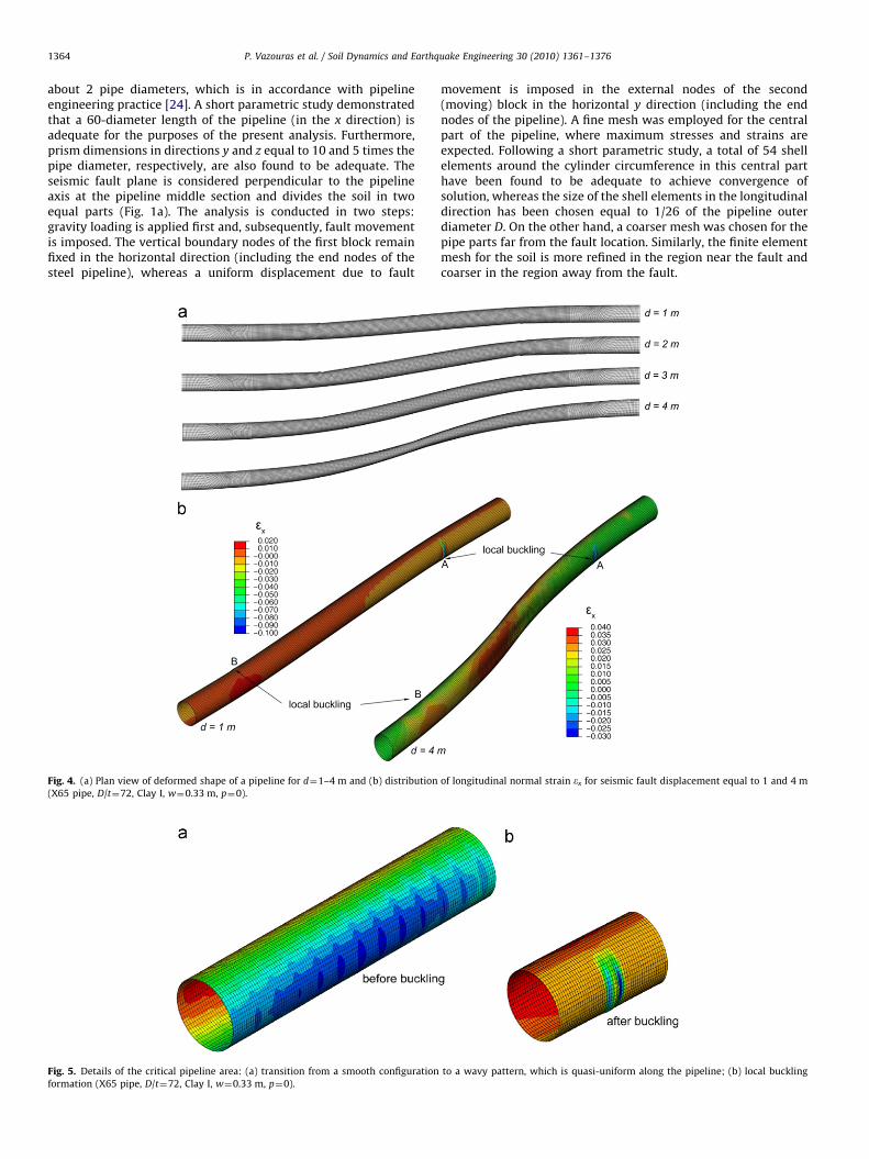
Fig. 4. (a) Plan view of deformed shape of a pipeline for d¼1–4 m and (b) distribution
(X65 pipe, D/t¼72, Clay I, w¼0.33 m, p¼0).
Fig. 5. Details of the critical pipeline area: (a) transition from a smooth configuration
formation (X65 pipe, D/t¼72, Clay I, w¼0.33 m, p¼0).
movement is imposed in the external nodes of the second(moving) block in the horizontal y direction (including the endnodes of the pipeline). A fine mesh was employed for the centralpart of the pipeline, where maximum stresses and strains areexpected. Following a short parametric study, a total of 54 shellelements around the cylinder circumference in this central parthave been found to be adequate to achieve convergence ofsolution, whereas the size of the shell elements in the longitudinaldirection has been chosen equal to 1/26 of the pipeline outerdiameter D. On the other hand, a coarser mesh was chosen for thepipe parts far from the fault location. Similarly, the finite elementmesh for the soil is more refined in the region near the fault andcoarser in the region away from the fault.
of longitudinal normal strain ex for seismic fault displacement equal to 1 and 4 m
to a wavy pattern, which is quasi-uniform along the pipeline; (b) local buckling
P. Vazouras et al. / Soil Dynamics and Earthquake Engineering 30 (2010) 1361–1376 1365
Fig. 2a plots the soil–pipeline system after a seismic faultmovement in the y direction. The fault movement is considered tooccur within a narrow transverse zone of width w, a common practicein several recent numerical studies of fault–foundation interaction[25,26]. Using this approach, it is possible to avoid discontinuity at thevicinity of the fault, which sometimes causes numerical problems.Furthermore, this consideration may correspond to a more realisticrepresentation of the fault displacement mechanism, as demonstratedin small scale model tests [27]. The sensitivity of numerical resultswith respect to the width w of that narrow zone is examined in asubsequent section of the paper.
Elastic–plastic material behavior is considered for both thepipeline and soil. A large-strain J2 flow (von Mises) plasticity modelwith isotropic hardening is employed to describe the mechanicalbehavior of the steel pipe material, calibrated through an appropriateuniaxial stress–strain curve from a tensile test. Furthermore, anelastic–perfectly plastic Mohr–Coulomb model is considered for thesoil behavior, characterized by the soil cohesiveness c, the frictionangle j, the elastic modulus E, and Poisson’s ratio v. The dilationangle c is assumed to be equal to zero throughout this study.
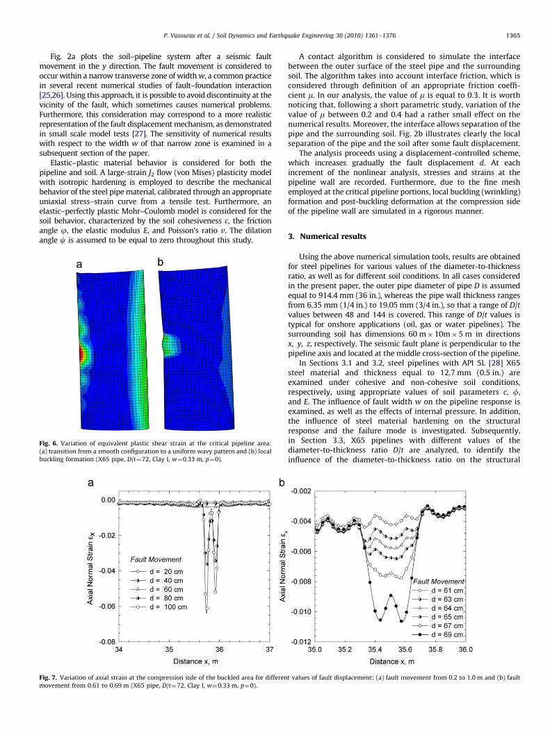
Fig. 6. Variation of equivalent plastic shear strain at the critical pipeline area:
(a) transition from a smooth configuration to a uniform wavy pattern and (b) local
buckling formation (X65 pipe, D/t¼72, Clay I, w¼0.33 m, p¼0).
Fig. 7. Variation of axial strain at the compression side of the buckled area for differen
movement from 0.61 to 0.69 m (X65 pipe, D/t¼72, Clay I, w¼0.33 m, p¼0).
A contact algorithm is considered to simulate the interfacebetween the outer surface of the steel pipe and the surroundingsoil. The algorithm takes into account interface friction, which isconsidered through definition of an appropriate friction coeffi-cient m. In our analysis, the value of m is equal to 0.3. It is worthnoticing that, following a short parametric study, variation of thevalue of m between 0.2 and 0.4 had a rather small effect on thenumerical results. Moreover, the interface allows separation of thepipe and the surrounding soil. Fig. 2b illustrates clearly the localseparation of the pipe and the soil after some fault displacement.
The analysis proceeds using a displacement-controlled scheme,which increases gradually the fault displacement d. At eachincrement of the nonlinear analysis, stresses and strains at thepipeline wall are recorded. Furthermore, due to the fine meshemployed at the critical pipeline portions, local buckling (wrinkling)formation and post-buckling deformation at the compression sideof the pipeline wall are simulated in a rigorous manner.
3. Numerical results
Using the above numerical simulation tools, results are obtainedfor steel pipelines for various values of the diameter-to-thicknessratio, as well as for different soil conditions. In all cases consideredin the present paper, the outer pipe diameter of pipe D is assumedequal to 914.4 mm (36 in.), whereas the pipe wall thickness rangesfrom 6.35 mm (1/4 in.) to 19.05 mm (3/4 in.), so that a range of D/tvalues between 48 and 144 is covered. This range of D/t values istypical for onshore applications (oil, gas or water pipelines). Thesurrounding soil has dimensions 60 m�10m�5 m in directionsx, y, z, respectively. The seismic fault plane is perpendicular to thepipeline axis and located at the middle cross-section of the pipeline.
In Sections 3.1 and 3.2, steel pipelines with API 5L [28] X65steel material and thickness equal to 12.7 mm (0.5 in.) areexamined under cohesive and non-cohesive soil conditions,respectively, using appropriate values of soil parameters c, f,and E. The influence of fault width w on the pipeline response isexamined, as well as the effects of internal pressure. In addition,the influence of steel material hardening on the structuralresponse and the failure mode is investigated. Subsequently,in Section 3.3, X65 pipelines with different values of thediameter-to-thickness ratio D/t are analyzed, to identify theinfluence of the diameter-to-thickness ratio on the structural
t values of fault displacement: (a) fault movement from 0.2 to 1.0 m and (b) fault

P. Vazouras et al. / Soil Dynamics and Earthquake Engineering 30 (2010) 1361–13761366
response. Finally, high-strength steel X80 pipelines under faultimposed deformations are analyzed in Section 3.4.
3.1. Moderately thick X65 steel pipeline in cohesive soils
A moderately thick-walled X65 pipeline is considered first, withdiameter and thickness equal to 914.4 mm (36 in.) and 12.7 mm(0.5 in.), respectively, so that D/t¼72. The API 5L X65 steel materialis a typical steel material for oil and gas pipeline applications, witha nominal stress-engineering strain curve shown with a solid linein Fig. 3a, obtained from a uniaxial tensile test. The yield stress sy isequal to 450 MPa (65 ksi) followed by a plastic plateau up to 3%strain and a strain-hardening regime with a hardening modulusequal to about Es/300, where Es is Young’s modulus of the steelmaterial. Considering a safety (reduction) factor equal to 0.72[29,30], the maximum operating pressure pmax of this pipeline,
Fig. 8. Variation of axial strain at the tension side of the buckled area for values of
fault displacement from 0.2 to 1.0 m (X65 pipe, D/t¼72, Clay I, w¼0.33 m, p¼0).
Fig. 9. Variation of axial strain at the compression side of the buckled area for differen
movement from 0.60 to 0.69 m (X65 pipe, D/t¼72, Clay I, w¼1 m, p¼0).
given by the following expression:
pmax ¼ 0:72� 2syt
D
� �ð1Þ
can be readily calculated equal to 9 MPa (90 barr).The pipeline is assumed to be imbedded in a cohesive soil and
to be crossing a fault zone having a width w equal to 0.33 m. Itsinternal pressure p is equal to zero, but it is increasedsubsequently in the present study. First, a soft-to-firm clay isconsidered, referred to as Clay I, which under ‘‘undrained’’ loadingconditions has a cohesion c¼50 kPa, friction angle j¼01, Young’smodulus E¼25 MPa and Poisson’s ratio n¼0.5.
Fig. 4a depicts the shape of the deformed pipeline at faultdisplacements d¼1–4 m in the area near the fault. Moreover,Fig. 4b plots depict the shape of the deformed pipeline and thedistribution of the longitudinal normal strain ex on its outersurface at fault displacement equal to d¼1 and d¼4 m. Thedeformed shape of the pipeline at d¼1 m shows a localizeddeformation at point A, referred to as ‘‘local buckling’’ or‘‘kinking’’, whereas point A is the ‘‘critical location’’ of thepipeline, at a distance of 5.45 m from the fault. Due to theskew-symmetry of the problem, a similar local deformationpattern occurs at point B, on the hidden side of the pipeline.Under increasing fault movement, a substantial development ofthis localized deformation pattern is observed, associated withthe distortion of a significant part of the pipeline around this area,as shown in Fig. 4b, for a fault displacement of d¼4 m. As thepipeline length increases with continued fault movement, itresults in higher tensile and smaller compressive strains in thelongitudinal direction. This is shown in Fig. 4b, where for a faultdisplacement of d¼4 m compressive longitudinal strains aresignificantly lower than those corresponding to a faultdisplacement of d¼1 m. The overtaking of the tensile strainsafter some critical value of d is discussed later in the paper.
Fig. 5 shows two consecutive deformed shapes of the pipelineat fault displacements d equal to 0.2 and 1 m, whereas Fig. 6 plotsthe same deformed shapes in a plan view. The localized bucklingpattern depicted in Figs. 5 and 6 develops on the critical locationalong the pipeline, where the compressive stresses and strains,and the corresponding bending curvature reach a maximumvalue. It is interesting to note that the buckled shape of thecompressed wall is formed in two stages. First a transition from a
t values of fault displacement: (a) fault movement from 0.2 to 1.0 m and (b) fault

P. Vazouras et al. / Soil Dynamics and Earthquake Engineering 30 (2010) 1361–1376 1367
‘‘smooth’’ deformation shape to a ‘‘wavy’’ pattern occurs, in theform of quasi-uniform wrinkling along a certain part of thepipeline about the critical cross-section, as shown clearly inFig. 5a. Subsequently, one of the wrinkles becomes dominant andthe deformation localizes (‘‘buckle localization’’), forming a sharp‘‘kink’’ or ‘‘local buckle’’, depicted in Fig. 5b. This mechanism ofbuckle initiation and localization is in accordance with previousexperimental observations in metal cylinders subjected tobending [31,32]. It is also important to notice that, upon localbuckling formation, the deformation of the pipeline localizes inthe vicinity of the buckle, as shown in Fig. 5b. The variations oflongitudinal compressive and tensile strain ex along the two outer(most stressed) generators of the pipe cylinder are shown inFigs. 7 and 8 for different values of the fault displacement and fora small segment of the pipeline about the critical area. The resultsfor the compressive strain shown in detail in Fig. 7b indicate thatfor a value of fault displacement greater than 0.67 m, significantdistortion of the cross-section occurs due to the development of alocalized wrinkling pattern (local buckling) on the pipe wall, onthe compression side of the deformed pipeline. This stage isconsidered as the onset of local buckling.
Fig. 11. Variation of axial strain at the compression side of the buckled area for differen
movement from 0.53 to 0.58 m (X65 pipe, D/t¼72, Clay I, w¼0.33 m, p¼0.56pmax).
Fig. 10. Variation of equivalent plastic shear strain at the critical pipeline area:
(a) transition from a smooth configuration to a uniform wavy pattern and (b) local
buckling formation (X65 pipe, D/t¼72, Clay I, w¼0.33 m, p¼0.56pmax).
It should be noted that determining the value of faultdisplacement at which onset of localized buckling occurs (dcr),referred to as ‘‘critical fault displacement’’, can be defined in manyways. In the present work, the onset of local buckling isconsidered at the stage where outward displacement of the pipewall starts at the area of maximum compression. At that stage,bending strains due to pipe wall wrinkling develop (Fig. 7),associated with significant tensile strains at the ‘‘ridge’’ of thebuckle, so that the longitudinal compressive strains at thislocation at the outer surface of the pipe wall start decreasing,forming a short wave at this location. In the present case, thisstage corresponds to a fault displacement equal to 0.67 m asshown in Fig. 7b.
At the above stage of local buckling onset, the longitudinalstrain at the location of the buckle (ecr) is measured equal to7.7�10�3. Furthermore, at this critical buckling stage, the
t values of fault displacement: (a) fault movement from 0.2 to 1.0 m and (b) fault
Fig. 12. Variation of axial strain at the tension side of the buckled area for different
values of fault displacement from 0.2 to 1.0 m (X65 pipe, D/t¼72, Clay I,
w¼0.33 m, p¼0.56pmax).

P. Vazouras et al. / Soil Dynamics and Earthquake Engineering 30 (2010) 1361–13761368
maximum tensile strain on the opposite side of the pipe (eT, max) is5.2�10�3, which is much less than the strain that would causetensile failure in the form of rupture in a non-seriously defectedpipeline [34,35]. Beyond the formation of the local buckle, pipedeformation concentrates around the buckled cross-section, andthe localized wrinkling pattern is significantly developed. Furthercontinuation of the imposed deformation results in pipe wallfolding, which is accompanied by significant local strains(compressive and tensile) at the buckled area. Similarly, themaximum tensile strain on the opposite (tensile) side of the pipeis also significantly increased. Those local tensile stresses, oneither side of the pipeline cross-section, may lead to local fractureat welds or other locations where minor defects exist, resultingin loss of pipeline containment with possibly catastrophicconsequences for the population and the environment.
The effects of the size of fault zone w on the mechanicalresponse of the pipeline are also examined. Finite elementanalyses have been conducted for several values of w rangingfrom 0.33 to 1.0 m. The numerical results indicated that that thewidth of the fault zone w has a minor effect on the response of thepipeline; this can be readily verified by comparing the results ofFig. 9 with those depicted in Fig. 7.
The effects of internal pressure on pipeline mechanicalbehavior are investigated by considering internally pressurized
Fig. 14. Variation of axial strain at the compression side of the buckled area for differen
movement from 0.60 to 0.65 m (X65 pipe, D/t¼72, Clay I, w¼0.33 m, p¼0.28pmax).
Fig. 13. Variation of equivalent plastic shear strain at the critical pipeline area:
(a) transition from a smooth configuration to a uniform wavy pattern and (b) local
buckling formation (X65 pipe, D/t¼72, Clay I, w¼0.33 m, p¼0.28pmax).
pipelines imbedded in the same soil conditions (Clay I). Thenumerical results presented in Fig. 10–12 correspond to apressure level of 50 barr, which is equal to 56% of the maximumoperating pressure pmax expressed by Eq. (1), whereas the resultsin Figs. 13–15 refer to a pressure level of 25 barr, which is equal to28% of pmax. Despite the fact that the buckled shapes shown inFig. 10 and in Fig. 13 are similar to the buckled shape of Fig. 6, thecorresponding values of critical fault displacement dcr and thecompressive strain along the critical generator of the steelpipeline shown in Fig. 11b and in Fig. 14b are lower than theones shown in Fig. 7b. These results indicate that, in the case ofburied (confined) pipes, the presence of internal pressure resultsin a decrease of critical fault displacement. The decrease isattributed to the development of additional stresses and strains inthe pipeline wall that cause early yielding and lead to a prematurelocal buckling failure. This implies a different structural behavior
t values of fault displacement: (a) fault movement from 0.2 to 1.0 m and (b) fault
Fig. 15. Variation of axial strain at the tension side of the buckled area for different
values of fault displacement from 0.2 to 1.0 m (X65 pipe, D/t¼72, Clay I,
w¼0.33 m, p¼0.28pmax).

Fig. 16. Variation of axial strain at the compression side of the buckled area for X65 steel with no hardening: (a) fault movement from 0.2 to 1.0 m and (b) fault movement
from 0.60 to 0.67 m (D/t¼72, Clay I, w¼0.33 m, p¼0).
Fig. 17. Variation of axial strain at the tension side of the buckled area for X65
steel with no hardening and different values of fault displacement from 0.2 to
1.0 m (D/t¼72, Clay I, w¼0.33 m, p¼0).
Fig. 18. Variation of equivalent plastic shear strain at the critical pipeline area:
(a) onset of local buckling and (b) post-buckling configuration (X65 pipe, D/t¼72,
Clay II, w¼0.33 m, p¼0).
P. Vazouras et al. / Soil Dynamics and Earthquake Engineering 30 (2010) 1361–1376 1369
than the one observed in bending tests of laterally unconfinedpipes [31,33], due to the presence of surrounding soil that has asignificant confinement effect. For the case of p/pmax¼0.56, themaximum strain ecr at buckling (critical strain) is equal to8.3�10�03, which is similar yet slightly higher than the criticalstrain for zero pressure.
The structural response of the same steel pipeline is shown inFig. 16 and in Fig. 17 considering an elastic–plastic material of450 MPa yield stress (same as in X65) but with perfect plasticity(no hardening). The stress–strain curve of this material is plottedwith the dotted line in Fig. 3a. The values of soil parameters c, E,and f are equal to 50 kPa, 25 MPa, and 01, respectively (Clay I).The critical fault displacement has been computed equal to67 cm. Comparison of those results with the results in Figs. 7 and8 indicates that the hardening of the steel material has anegligible influence on the structural response of the pipeline
subjected to strike-slip fault displacement perpendicular to thepipeline axis.
The numerical results in Figs. 18–20 refer to an X65 steel pipelinewith D/t ratio equal to 72, buried in stiffer cohesive soil conditions.The values of soil parameters c, E, and f are equal to 200 kPa,100 MPa, and 01, respectively, and correspond to a stiff clay under‘‘undrained conditions’’, referred to as Clay II. The width of the faultzone is equal to 0.33 m. The numerical results indicate thatpipe bending deformation in the stiff soil occurs within a shorterdistance from the fault location, and the critical area is at 3.2 m fromthe fault. Comparison of those results with the results shown inFigs. 6–8 demonstrates the significant effect of site conditionson the mechanical behavior of the steel pipeline. In other words, forthe same fault displacement d, higher bending stresses and strainsoccur in the case of a stiff soil than those in the case of a soft soil.The numerical verification of the above observation is offered inFigs. 19 and 20, which depict the variation of longitudinal (axial)normal strain along the compression generator. Local bucklingoccurs when the fault displacement becomes equal to 0.23 m, whichis much less than the corresponding critical fault displacementfor the case of soft clay (0.67 m). The corresponding maximum

Fig. 19. Variation of axial strain at the compression side of the buckled area for different values of fault displacement: (a) fault movement from 0.2 to 1.0 m and (b) fault
movement from 0.20 to 0.25 m (X65 pipe, D/t¼72, Clay II, w¼0.33 m, p¼0).
Fig. 20. Variation of axial strain at the tension side of the buckled area for different
values of fault displacement from 0.2 to 1.0 m (X65 pipe, D/t¼72, Clay II,
w¼0.33 m, p¼0).
P. Vazouras et al. / Soil Dynamics and Earthquake Engineering 30 (2010) 1361–13761370
compressive strain ecr that causes local buckling is equal to7.3�10�3, whereas the maximum tensile strain eT, max along theopposite generator at the stage of local buckling onset is equal to4.8�10�3. The striking difference between softer and stiffer soilconditions is attributed to the fact that a steel pipeline in asofter soil, when subjected to a fault displacement, accommodatesitself easier within the deformable soil, resulting in lower bendingstresses and strains, which enable the pipeline to sustain largerground-imposed displacements.
3.2. Moderately thick X65 steel pipeline in non-cohesive soils
The response of an X65 steel pipeline with D/t¼72 embedded innon-cohesive soils is examined, by considering representativeresults for two frictional soils and comparing them to those obtained
for the cohesive soils. First, a granular soil is considered with afriction angle f¼301, Young’s modulus E¼8 MPa and Poisson’s ratiov¼0.3, corresponding to loose sand and referred to as ‘‘Sand I’’. Therelatively small value of the stress-depended Young’s modulus E isjustified by the shallow embedment depth of the pipeline. A smallamount of artificial cohesion equal to c¼5 kPa was also included toprevent numerical difficulties associated with the behavior of apurely frictional material at very small confining stress, such as inthe case of a gap opening at the pipe–soil interface. Figs. 21 and 22show the variation of the axial strain ex along the compression andtension outer sides, respectively, of the buckled area for Sand I. Thecritical distance from the fault, corresponding to the point withmaximum bending curvature along the pipe, is 6.1 m. The results forthe compressive strain shown in Fig. 21 indicate that at a value offault displacement equal to 0.87 m, local buckling occurs, andbeyond this stage, significant distortion of the cross-section occursdue to local buckling on the pipe wall on the compression side of thebent pipeline. The shape of the developing buckling is similar to thatof Clay I. The longitudinal strain at the location of the buckle (ecr) isequal to 9.7�10�3. Furthermore, at the critical buckling stage(d¼0.87 m), the maximum tensile strain on the opposite side of thepipe (eT, max) is 6.8�10�3, which is much less than the strain thatwould cause tensile rupture. Beyond the formation of the localbuckle, pipe deformation concentrates around the buckled cross-section and the localized wrinkling pattern is further developed.Further continuation of the imposed deformation results in pipe wallfolding, which is accompanied by significant local strains(compressive and tensile) at the buckled area. Moreover, themaximum tensile strain on the opposite (tensile) side of the pipeis also significantly increased.
Similarly, Figs. 23 and 24 present the results for an X65 steelpipeline with D/t¼72, embedded in a more dense sand withvalues of f and E equal to 401 and 50 MPa, respectively, referredto as ‘‘Sand II’’. The numerical results indicate that pipe bendingdeformation in Sand II occurs within a shorter distance from thefault location (5.1 m) due to the higher strength of this sand.Comparison of those results with the results in Figs. 21 and 22demonstrates that for the same fault displacement d, higherbending stresses and strains occur in the case of Sand II. Localbuckling occurs when the fault displacement becomes equal to0.70 m, which is less than the corresponding critical faultdisplacement for the case of loose sand (0.87 m). The maximum

Fig. 21. Variation of axial strain at the compression side of the buckled area for different values of fault displacement (a) fault movement from 0.2 to 1.0 m and (b) fault
movement from 0.70 to 0.90 m (X65 pipe, D/t¼72, Sand I, w¼0.33 m, p¼0).
Fig. 22. Variation of axial strain at the tension side of the buckled area for different
values of fault displacement from 0.2 to 1.0 m (X65 pipe, D/t¼72, Sand I,
w¼0.33 m, p¼0).
P. Vazouras et al. / Soil Dynamics and Earthquake Engineering 30 (2010) 1361–1376 1371
compressive strain ecr that causes local buckling is equal to10.47�10�3, whereas the corresponding maximum tensile straineT, max along the opposite generator is equal to 6.98�10�3.
3.3. Effects of the diameter-to-thickness ratio and design
implications
In order to investigate the effects of the diameter-to-thicknessratio, results are obtained for 36-in.-diameter X65 steel pipelineswith thickness ranging between 1/4 and 3/4-in., corresponding toD/t values between 48 and 144. Both cohesive soils (Clay I and II)and non-cohesive soils (Sand I and II) are considered.
The numerical results for cohesive soils (Clay I and II) aresummarized in Fig. 25. In particular, Fig. 25a plots the fault criticaldisplacement, dcr, normalized by the pipe diameter D, in terms ofthe diameter-to-thickness ratio, D/t. The results show a
substantial decrease of dcr with increasing value of the D/t ratio,which means that thin-walled pipelines are more prone tobuckling and fail at relatively small values of fault displacement.Furthermore, stiff soil conditions result in significantly lowerdeformation capacity of the pipeline. In Fig. 25b the corres-ponding critical compressive strain at the onset of local buckling,ecr, is plotted against the value of the diameter-to-thickness ratio,D/t. The results indicate that thinner pipes buckle at smallercritical strain, which is in accordance with test data and numericalresults from non-confined pipes [31–33].
In the above results, no critical displacement or critical strain isshown for D/t¼44 and soft soil conditions (Clay I). In this particularcase, the numerical results did not indicate local buckling; thepipeline exhibited significant ground-induced deformation withoutany wrinkling of the pipeline wall for fault displacements thatexceed 2.5 m. The tensile strains developed in the pipeline due tolongitudinal pipeline stretching are responsible for this behavior.Using a realistic approximation of the deformed shape of thepipeline, it is possible to develop a simplified analysis (seeAppendix), which demonstrates the opposite effects of longitudinalbending and stretching, and results in the simple ‘‘no-buckling’’condition equation (15). Adopting a value of a equal to 0.5 andassuming that L/DE16 for soft cohesive conditions (Clay I), asshown in Fig. 29 of the Appendix, then from equation (15), thelimiting D/t value is equal to 53. This is somewhat higher than theD/t value of the pipeline under consideration (D/t¼44), so thatthe ‘‘no-buckling’’ condition (15) is satisfied.
In Fig. 25b, the finite element results for the critical strain (ecr)are also compared with the predictions of the new Europeanstandard EN 1998-4 [35] for seismic design of buried pipelines,also adopted by the very recent ASCE Manual of Practice 119 forBuried Steel Pipes [36]. The EN 1998-4 standard specifies amaximum allowable strain for compression (eC,w) equal to theminimum of [0.01, 0.4t/D] and a maximum allowable tensilestrain (eT,w) equal to 0.03. The finite element results predict adecrease of the critical strain with increasing D/t values, which isin accordance with the provisions in [35,36]. However, it shouldbe noticed that the allowable compressive strain appears to beconservative for the range of cohesive soil conditions expressedby Clay I and Clay II as shown in Fig. 25b.
Moreover, the numerical results of axial strain at the tensionside of the pipe for all the cases considered in Fig. 25 show that atthe onset of local buckling the computed maximum tensile strain

Fig. 23. Variation of axial strain at the compression side of the buckled area for different values of fault displacement: (a) fault movement from 0.2 to 1.0 m and (b) fault
movement from 0.60 to 0.75 m (X65 pipe, D/t¼72, Sand II, w¼0.33 m, p¼0).
Fig. 24. Variation of axial strain at the tension side of the buckled area for different
values of fault movement from 0.2 to 1.0 m (X65 pipe, D/t¼72, Sand II, w¼0.33 m,
p¼0).
P. Vazouras et al. / Soil Dynamics and Earthquake Engineering 30 (2010) 1361–13761372
eT, max varies from 0.002 to 0.01, which is significantly lower thanthe EN 1998-4 allowable value of eT,w¼0.03. This observationverifies that for the range of parameters considered in the presentstudy, local buckling rather than tensile rupture is the governingmode of pipeline mechanical response.
In Fig. 25, the effects of internal pressure are also depicted. Thenumerical results are obtained for a pressure level equal to 56% ofthe maximum operating pressure, pmax, and show that the presenceof internal pressure results in a small decrease of critical faultmovement, dcr in Fig. 25a, due to the additional stresses and strainsin the pipeline wall because of pressure. Furthermore, thecorresponding critical strain in the presence of pressure is similarto the corresponding critical strain for the zero pressure case, asshown in Fig. 25b. Note that EN 1998-4 provisions [35] specify avalue of critical strain independent of the level of internal pressure,and this is in accordance with the present numerical results.
Finally, the numerical results for the mechanical behavior ofX65 pipelines in non-cohesive soils (Sand I and II) are summarizedin Fig. 26, in terms of the normalized fault critical displacementand the critical corresponding strain at buckling with respect tothe diameter-to-thickness ratio, D/t. The results shown in Fig. 26aindicate that dense soil conditions (Sand II) result in lowerdeformation capacity of the pipeline. Furthermore, for bothground conditions, the critical compressive strain, ecr, shown inFig. 26b, is significantly higher than the one predicted by theprovisions of EN 1998-4 [35].
3.4. Structural behavior of high-strength X80 steel pipelines
The behavior of buried high-strength steel (API X80) pipelinesunder fault-induced deformation is also analyzed, using thenumerical tools described in the previous sections. The nominaluniaxial tensile stress–strain relationship of the X80 material isplotted in Fig. 3b. The dashed material curve, which has a yieldstress of 596 MPa and does not have a plastic plateau, correspondsto a cold expanded (UOE) pipe. The solid material curve with ayield stress of 550 MPa and a plastic plateau up to a strain of1.48% represents a seamless steel pipe material. Results areobtained for 36-in.-diameter X80 steel pipelines with D/t ratiosbetween 48 and 144.
Fig. 27a plots the value of the fault critical displacement, dcr,normalized by the pipe diameter D, in terms of the diameter-to-thickness ratio, D/t, for the two types of X80 steel (shown inFig. 3b) and for cohesive soil conditions (Clay I and II). As in thecase of X65, the value of dcr decreases significantly with increasingvalue of D/t, indicating that thin-walled pipelines are morevulnerable to buckling and may fail at relatively small values offault displacement. It should be noted that for the softer Clay Imaterial, no values of dcr are given for D/t¼44 and 72, as nowrinkling of the pipeline wall was observed in this case even forfault displacements exceeding 4 m. This is attributed to thebeneficial effect of tensile deformation on the mechanicalbehavior of those relatively thick pipes, as described in theAppendix. Naturally, the values of dcr for the high-strength steelX80 pipes in Fig. 27a are higher than those for the X65 pipesgiven in Fig. 25a. Similarly, Fig. 27b plots the correspondingcritical axial strain, ecr, versus the diameter-to-thickness ratio, D/t,for zero internal pressure. Also plotted in the figure is the

Fig. 25. (a) Critical fault movement versus the diameter-to-thickness ratio D/t for Clay I, II and (b) critical axial strain versus the diameter-to-thickness ratio D/t for clay I,
II—predictions from EN 1998-4 (X65 pipe, w¼0.33 m, p¼0 and p¼0.56pmax).
Fig. 26. (a) Critical fault movement versus the diameter-to-thickness ratio D/t for Sand I, II and (b) critical axial strain versus the diameter-to-thickness ratio D/t for Sand I,
II—predictions from EN 1998-4 (X65 pipe, w¼0.33 m, p¼0).
Fig. 27. (a) Critical fault movement versus the diameter-to-thickness ratio D/t for two different types of X80 pipelines and (b) Critical axial strain versus the diameter-to-
thickness ratio D/t for two different types of X80—predictions from EN 1998-4 (X80 pipe, w¼0.33 m, p¼0).
P. Vazouras et al. / Soil Dynamics and Earthquake Engineering 30 (2010) 1361–1376 1373

P. Vazouras et al. / Soil Dynamics and Earthquake Engineering 30 (2010) 1361–13761374
recommendation by the EN 1998-4 giving more conservativevalues of ecr. Comparing the behavior of the two X80 materials, itis evident that both dcr and ecr are higher for UOE pipe due to bothincrease of yield strength and higher initial post-yielding tangentmodulus. The increase of buckling strength in UOE pipes is inaccordance with the test data reported in [37,38].
Finally, the numerical results for the maximum axial strain ex atthe tension side of the pipe at the onset of local buckling have beenfound to be significantly lower than the EN 1998-4 [35] allowablevalue of eT,w¼0.03 for all values of D/t ratio examined in this paper.
non-deformed pipeline axis
x
z
y
L
d
u (x)
u (x
)/d
4. Conclusions
Using advanced finite element simulation tools, the mechan-ical behavior of buried steel pipelines crossing an active strike-slipfault was investigated. The pipeline is assumed horizontal andnormal to the fault plane, an idealized case, which allows for theinvestigation of several soil and pipe parameters on pipelinedeformation and strength. In particular, the effects of variouscohesive and non-cohesive soil conditions (expressed throughvarious values of soil cohesion, friction, and stiffness parameters(c, f, E)) on the structural response of the pipe are examined, withparticular emphasis on pipe wall failure due to wrinkling (localbuckling) or rupture.
An extensive parametric study is conducted, and numericalresults are obtained for various values of D/t ratio and for X65 andX80 steel pipelines. In the majority of the cases analyzed, it isshown that the formation of local buckling due to excessivecompressive strains at the pipeline wall is the governing mode offailure. The numerical results are presented in diagram form forthe critical fault displacement dcr and the corresponding criticalstrain ecr, and indicate a strong dependence in terms of thepipeline diameter-to-thickness ratio D/t.
It is concluded that in cohesive soils, softer ground conditionsresult in a large deformation capacity of the pipeline, whereas stiffground conditions decrease the critical fault displacement.Similarly, in non-cohesive soils, loose sand conditions results inlarger values of critical fault displacement than in dense soilconditions. The width of the fault slip zone was found to havenon-important effects for the mechanical behavior of the pipe. Itwas demonstrated that the presence of internal pressure resultsin a small decrease of the deformation capacity, due to earlyyielding of the steel material. It was also concluded that high-strength X80 steel pipelines have a greater deformation capacitythan X65 pipelines. Furthermore, cold-formed UOE X80 pipesexhibit better behavior in terms of buckling than seamless X80pipes due to strain hardening.
Furthermore, the numerical results show that thick-walled pipesmay not exhibit buckling; in those pipelines wall fracture mayoccur due to the development of excessive tensile strains. Asimple analytical model is developed for illustrating this behavior,resulting in a simple ‘‘no-buckling’’ condition, expressed by Eq. (15).
Finally, the results from the present study are compared withthe provisions of recent design standards and recommendationsof EN 1998-4 and ASCE MOP 119, and can be used for buried steelpipeline design purposes, in the framework of a strain-basedpipeline design.
x/L
Fig. 28. (a) Assumed shape function u(x) for pipeline longitudinal deformation;
(b) comparison of the pipeline assumed shape at the onset of buckling from
equation (2) and the finite element analysis (X65 pipe, D/t¼72, Clay I, w¼0.33 m,
p¼0, d¼0.6 m).
Acknowledgements
The research work in this paper was partially supported by theFoundation of Education and European Civilization, Athens,Greece, through a Doctorate Research Fellowship granted toMr. Polynikis Vazouras. This contribution is gratefully acknowledged.
Appendix. Simplified calculation of compressive strain
It is possible to develop a simplified formulation for pipelinedeformation under strike-slip fault normal to the pipe axis, toestimate under which conditions the compressive strains thatdevelop in the pipeline wall may cause local buckling. Towardsthis purpose, the pipeline is assumed to deform in an S-shaped‘‘shearing type’’ configuration, as shown in Fig. 28a. In the pre-buckling stage, the shape is smooth and free of localdiscontinuities. A shape function of the beam-type deformationof pipeline is assumed to be in the form:
uðxÞ ¼d
21�cos
px
L
� �ð2Þ
where d is the fault-imposed displacement and L is the lengthof the S-shaped deformed pipeline segment at the initial(non-deformed) pipeline configuration, i.e. the length of theS-shaped curved part of the pipeline in the fault area, as shown inFigs. 2 and 28a. Fig. 28b compares the shape of the deformedpipeline segment derived by the numerical analysis for Clay I(X65 pipe, D/t¼72, w¼0.33 m) to the assumed mathematicalshape given by Eq. (2), for a fault displacement equal to 0.6 m.The value of L decreases with increasing soil stiffness andincreasing D/t ratio, as shown in dimensionless form in Fig. 29for cohesive soil conditions. From Eq. (2), the maximum

Fig. 29. Dimensionless length L/D versus the diameter-to-thickness ratio D/t for
two different soil conditions (X65 pipe,w¼0.33 m, p¼0).
P. Vazouras et al. / Soil Dynamics and Earthquake Engineering 30 (2010) 1361–1376 1375
bending curvature k and the corresponding bending strain eb dueto the imposed deformation d can be readily computed as follows:
k¼�u00max ¼d
2
pL
� �2ð3Þ
eb ¼kD
2¼p2
4
d
L
� �D
L
� �ð4Þ
Furthermore, the increase of pipeline length between cross-sections at x¼0 and x¼L (pipeline stretching) is
D¼Z L
0
ffiffiffiffiffiffiffiffiffiffiffiffiffiffi1þuu2
qdx�L ð5Þ
so that the corresponding axial strain (also referred to as‘‘membrane’’ or ‘‘stretching’’ strain) em is
em ¼DL¼
1
L
Z L
0
ffiffiffiffiffiffiffiffiffiffiffiffiffiffi1þuu2
qdx�1 ð6Þ
which is assumed to be uniformly distributed along the pipeline.Using the following series expansion:ffiffiffiffiffiffiffiffiffiffiffiffiffiffi
1þuu2q
¼ 1þ1
2uu2þ � � � ð7Þ
and keeping only the first two terms, the axial membrane strainfrom Eq. (6) becomes
em ¼DLC
1
2L
Z L
0uu2 dx¼
d2p2
16L2ð8Þ
To compute the total axial compressive strain eC, the axial(tensile) membrane strain should be subtracted from thecompressive bending strain. Combining Eqs. , one obtains theaxial compressive strain at the critical location:
eC ¼ eb�em ¼p2
4L2Dd�
d2
4
� �ð9Þ
The above equation shows that the total compressive strainconsists of a linear part (due to bending) and a counteractingquadratic part (due to membrane axial tensile deformation). At thefirst stages of deformation, i.e. for small values of d, the membranestrain em is small and the bending strain eb governs the response. On
the other hand, the membrane strain em becomes dominant at laterdeformation stages (large values of d). The value of fault displace-ment at which the compressive strain eC reaches a maximum valueis readily obtained by differentiating equation (9):
deC
dd¼
p2
4L2D�
d
2
� �ð10Þ
Setting the above derivative equal to zero, one obtains
d� d0 ¼ 2D ð11Þ
so that the corresponding maximum value of compressive straineC is
eC,max ¼p2
4
D
L
� �2
ð12Þ
Beyond that stage, the value of compressive strain eC decreaseswith increasing fault displacement d.
If the maximum axial compressive strain eC, max in Eq. (12) islower than the buckling (critical) strain ecr of the pipeline wall,local buckling may not occur. This is expressed mathematically asfollows:
eC,maxrecr ð13Þ
In the above equation, the buckling (critical) strain ecr can bewritten in the following form [35]:
ecr ¼ at
D
� �ð14Þ
where a is a constant that depends on the pipeline material grade,as well as the amplitude and shape of initial imperfections.Inserting Eqs. (12) and (14) into Eq. (13), one obtains thefollowing ‘‘no-buckling’’ condition in terms of the diameter-to-thickness ratio D/t, the dimensionless parameter a and the length-over-diameter ratio L/D of the S-shaped deformed pipeline:
D
tr
D
t
� �lim
¼ 0:4a L
D
� �2
ð15Þ
The above expression shows that, in the case of strike-slipfaults perpendicular to the pipeline axis, in order to avoid localbuckling of the pipeline, the diameter-to-thickness ratio D/tshould not exceed the limit value (D/t)lim given in Eq. (15). Thislimit value depends on the pipeline material (which influence thevalue of the dimensionless parameter a) and the soil conditions(which have a direct effect on the value of the L/D ratio).
Moreover, Eq. (15) can be employed to derive some usefulqualitative results. More specifically, Eq. (15) indicates that steelpipelines embedded in relatively stiff soil conditions should bequite thick-walled (i.e. have a low value of D/t ratio) in order toavoid local buckling, whereas soft ground conditions relax thisrequirement. Furthermore, the use of high-strength steel forpipeline material (e.g. steel grade API 5L X80) results in an increaseof parameter a, thus increasing pipeline ability to deform underground-induced actions without the occurrence of local buckling.
References
[1] Ariman T, Muleski GE. A review of the response of buried pipelines underseismic excitations. Earthquake Engineering and Structural Dynamics1981;9:133–51.
[2] Liang J, Sun S. Site effects on seismic behavior of pipelines: a review. ASMEJournal of Pressure Vessel Technology 2000;122(4):469–75.
[3] Jennings, P.C., 1971. Engineering features of the San Fernando earthquakeFebruary 9, 1971, California Institute of Technology Report, EERL 71–02,Pasedena, CA.

P. Vazouras et al. / Soil Dynamics and Earthquake Engineering 30 (2010) 1361–13761376
[4] MaCaffrey MA, O’Rourke TD. Buried pipeline response to reverse faultingduring the 1971 San Fernando Earthquake. ASME, PVP conference 1983;77:151–9.
[5] Desmod TP, Power MS, Taylor CL, Lau RW. Behavior of large-diameterpipeline at fault crossings. ASCE, TCLEE 1995(6):296–303.
[6] Nakata T, Hasuda K. Active fault I 1995 Hyogoken Nanbu earthquake. Kagaku1995;65:127–42.
[7] Earthquake Engineering Research Institute. Kocaeli, Turkey Earthquake ofAugust 17. EERI Special Earthquake Report, 1999.
[8] Takada S, Nakayama M, Ueno J, Tajima C. Report on Taiwan Earthquake.RCUSS, Earthquake Laboratory of Kobe University, 1999. p. 2–9.
[9] Newmark NM, Hall WJ. Pipeline design to resist large fault displacement. In:Proceedings of U.S. national conference on earthquake engineering, 1975.p. 416–25.
[10] Kennedy RP, Chow AW, Williamson RA. Fault movement effects on buried oilpipeline. ASCE Journal of Transportation Engineering 1977;103:617–33.
[11] Kennedy, R.P., Kincaid,, R.H. . Fault crossing design for buried gas oil pipelines.ASME, PVP conference 1983;77:1–9.
[12] Wang LRL, Yeh YA. A refined seismic analysis and design of buried pipelinefor fault movement. Earthquake Engineering and Structural Dynamics1985;13:75–96.
[13] Vougioukas EA, Theodossis C, Carydis PG. Seismic analysis of buried pipelinessubjected to vertical fault movement. ASCE Journal of Technical Councils1979;105(TCI):432–441.
[14] Wang LLR, Wang LJ. Parametric study of buried pipelines due to large faultmovement. ASCE, TCLEE 1995 1995(6):152–9.
[15] Takada S, Hassani N, Fukuda K. A new proposal for simplified design of buriedsteel pipes crossing active faults. Earthquake Engineering and StructuralDynamics 2001;30:1243–57.
[16] Kokavessis NK, Anagnostidis GS. Finite element modelling of buried pipelinessubjected to seismic loads: soil structure interaction using contact elements.In: Proceedings, ASME PVP conference, Vancouver, BC, Canada, 2006.
[17] Karamitros DK, Bouckovalas GD, Kouretzis GP. Stress analysis of buried steelpipelines at strike-slip fault crossings. Soil Dynamics and EarthquakeEngineering 2007;27:200–11.
[18] Liu M, Wang, Y-Y, Yu Z. Response of pipelines under fault crossing. In:Proceedings, international offshore and polar engineering conference, Vancouver,BC, Canada, 2008.
[19] Ha D, Abdoun TH, O’Rourke MJ, Symans MD, O’Rourke TD, Palmer MC, et al.Buried high-density polyethylene pipelines subjected to normal and strike-slipfaulting—a centrifuge investigation. Canadian Geotechnical Journal 2008;45:1733–42.
[20] Ha D, Abdoun TH, O’Rourke MJ, Symans MD, O’Rourke TD, Palmer MC, et al.Centrifuge modeling of earthquake effects on buried high-densitypolyethylene (HDPE) pipelines crossing fault zones. ASCE Journal ofGeotechnical and Geoenvironmental Engineering 2008;134(10):1501–15.
[21] Abdoun TH, Ha D, O’Rourke MJ, Symans MD, O’Rourke TD, Palmer MC, et al.Factors influencing the behavior of buried pipelines subjected to earthquakefaulting. Soil Dynamics and Earthquake Engineering 2009;29:415–27.
[22] Lillig DB, Newbury BD, Altstadt SA. The second ISOPE strain-based designsymposium—a review. In: Proceedings of the international society of offshoreand polar engineering conference, Osaka, Japan, 2009.
[23] ABAQUS. Users’ manual, version 6.7. Providence, RI, USA: Simulia; 2008.[24] Mohitpour M, Golshan H, Murray A. Pipeline design & construction: a
practical approach. third ed.. New York, NY: ASME Press; 2007.[25] Anastasopoulos I, Callerio A, Bransby MF, Davies MC, Nahas AEl, Faccioli E,
et al. Numerical analyses of fault foundation interaction. Bulletin ofEarthquake Engineering 2008;6(4):645–75.
[26] Gazetas G, Anastasopoulos I, Apostolou M. Shallow and deep foundationunder fault rapture or strong seismic shaking. In: Pitilakis K, editor. Earth-quake Geotechnical Engineering. Springer; 2007. p. 185–215.
[27] Bransby MF, Davies MC, Nahas AEl. Centrifuge modeling of normal fault-foundation interaction. Bulletin of Earthquake Engineering 2008;6(4):585–605.
[28] American Petroleum Institute. Specification for line pipe, 44th ed. ANSI/APISpec 5L, 2007.
[29] American Society of Mechanical Engineers. Pipeline transportation systemsfor liquid hydrocarbons and other liquids. ANSI/ASME 2006;B31:4.
[30] American Society of Mechanical Engineers. Gas transmission and distributionpiping systems. ANSI/ASME 2007;B31:8.
[31] Gresnigt AM. Plastic design of buried steel pipes in settlement areas. HERON1986;31(4):1–113.
[32] Kyriakides S, Ju GT. Bifurcation and localization instabilities in cylindricalshells under bending I: experiments. International Journal of Solids andStructures 1992;29:1117–42.
[33] Limam A, Corona E, Lee L-H, Kyriakides S. Inelastic wrinkling and collapse oftubes under combined bending and internal pressure. International Journal ofMechanical Sciences, in press (available online).
[34] Igi S, Suzuki, N. Tensile strain limits of X80 high-strain pipelines. In:Proceedings of the 16th international offshore and polar engineeringconference, Lisbon, Portugal, 2007.
[35] Comite Europeen de Normalisation. Eurocode 8, Part 4: Silos, tanks andpipelines. CEN EN 1998-4, Brussels, Belgium, 2006.
[36] American Society of Civil Engineers. Buried flexible steel pipe; design andstructural analysis. In: Whidden WR, editor. ASCE Manual of Practice, MOP;2009. p. 119.
[37] Gresnigt AM, van Foeken RJ. Local buckling of UOE and seamless steel pipes.In: Proceedings of the 11th international offshore and polar engineeringconference, Stavanger, Norway, vol. II, 2000. p. 131–42.
[38] Gresnigt AM, Karamanos SA. Local buckling strength and deformationcapacity of pipes. In: Proceedings of the 19th International Offshore andPolar Engineering Conference, Osaka, Japan, 2009. p. 212–23.