soil nails at gateway to nebraska - terracon nails at gateway to nebraska lok m. sharma, m.s., p.e.,...
TRANSCRIPT
SOIL NAILS AT GATEWAY TO NEBRASKA
Lok M. Sharma, M.S., P.E., Senior Principal Terracon Consultants, Inc.
13910 W 96th Terrace Lenexa, KS 66215
(913) 492-7777 [email protected]
Binod K. Sapkota, Ph.D., P.E., Geotechnical Engineering Specialist Bechtel Oil, Gas and Chemicals, Inc.
3000 Post Oak Boulevard Houston, TX 77056
(713) 235-3043 [email protected]
Prepared for the 62nd Highway Geology Symposium, July, 2011
62nd HGS 2011: Sharma, Sapkota 2
Acknowledgement The writers are indebted to George Schuler of the Judy Company for providing site photographs
and due cooperation in successful completion of this project. Our thanks are extended to the Nebraska Department of Roads for assignment.
Disclaimer
Statements and views presented in this paper are strictly those of the author(s), and do not necessarily reflect positions held by their affiliations, the Highway Geology Symposium (HGS), or others acknowledged above. The mention of trade names for commercial products does not
imply the approval or endorsement by HGS.
Copyright Notice
Copyright © 2011 Highway Geology Symposium (HGS)
All Rights Reserved. Printed in the United States of America. No part of this publication may be reproduced or copied in any form or by any means – graphic, electronic, or mechanical,
including photocopying, taping, or information storage and retrieval systems – without prior written permission of the HGS. This excludes the original author(s).

62nd HGS 2011: Sharma, Sapkota 3
INTRODUCTION The Gateway to Nebraska project consists of widening Interstate 80 from west of the existing bridge over Missouri River to 24th Street in Omaha, Nebraska near 13th Street. The widening project involved cutting into a hillside on the north side of Interstate 80. Cuts on the order of 46 feet were required necessitating the use of retaining walls to stay within the Interstate right-of-way. Comparison of various options of retaining walls resulted in adopting a three-tiered soil nail retaining wall. The soil nail wall had several advantages over other systems including reduced excavation, smaller impact on existing slope and flexibility in the facing design. Being a top down construction, the soil nail wall also provided speed in construction. The following paper describes the design and construction of a three tiered retaining wall using soil nails in a loessial deposit. The soil nail retaining walls were designed using the FHWA design guidelines as per Nebraska Department of Roads (NDOR). The location of the project is indicated in Figure 1.
Figure 1 – Project Location, Omaha, NE
Figure 1 – Project Location, Omaha, NE There are several walls that were designed and constructed to accommodate the highway widening at this project site. The walls were numbered from 1 to 7. Wall numbers 4, 5 and 6 are the three walls of the three-tiered retaining wall that are presented in this paper. Wall No. 4 being the lowest tier, wall No. 5 the middle tier and wall No. 6 the top tier. The total length of the three-tiered wall is approximately 1,380 feet (from station 1414+60 to station 1428+40). The maximum height of each tier varies from approximately 10 feet to 15 feet for a total height of about 46 including the undercut for the roadway. The natural ground above the top tier wall is sloped at approximately 3H:1V. A schematic of the walls is shown in Figure 2.

62nd HGS 2011: Sharma, Sapkota 4
Figure 2 – Three-Tiered Wall The soil nail wall at this site was a design build assignment. The following paper describes how the global stability was analyzed using both Limit Equilibrium Method (LEM) and FLAC numerical analysis method. SUBSURFACE AND SITE CONDITIONS The geotechnical subsurface exploration had been provided by NDOR. A copy of the geotechnical report “ Final Foundation Report – Interstate 80: Missouri River to 13th Street, Omaha NE, Report No: NH-80-9(899): CN 22132, dated April 10, 2009” was provided to us. There were specific borings along the proposed location of the wall. Data from four borings and three Cone Penetrometer Tests (CPT) were pertinent to the wall design. Borings MR1 and MR2 and CPT MR-1 were performed at about the crest elevation of the wall and Boring MS1 and MS2, and CPTs ms1 and ms2 were performed at about the toe elevation of the proposed wall. Table 1 below provides the soil profile obtained from the borings.
Table 1 – Soil Profile

62nd HGS 2011: Sharma, Sapkota 5
Based on the NDOR geotechnical report, published literature and our experience, the following soil data have been used
Soil Type Lean Clay (Loess) Moist Unit Weight 120 pcf Ultimate Friction Angle 27 degree Ultimate Cohesion 150 psf Young's Modulus 1x10^5 psf (For FLAC analysis) Poisson's Ratio 0.35 (For FLAC analysis) Ultimate Tension 75 psf (Tension cut-off) (For FLAC analysis) Ultimate Soil Nail Grout/Soil Bond Strength 10 psi
SOIL NAIL WALL The design of a three-tiered wall presented certain challenges at this site. The subsurface conditions largely involved “Peoria” loess deposits. Use of soil nails in loessial deposit is always looked upon with caution. The sensitive nature of loess, especially the loss of strength in the presence of water is of major concern. The Peoria loess at this site was found to be very stiff with dense structure. The three tiered soil nail wall was designed using the FHWA design guidelines. Starting from the top tier, each tier of wall was considered as a surcharge on the lower wall for global stability analysis using Limit Equilibrium Method (LEM) computer software “SNAIL” developed by CalTrans. The LEM analysis was verified using the “FLAC” computer program. The FLAC analysis model assessed global stability and also calculated the pull out stresses in soil nails. The lengths of the nails were primarily controlled by global stability. The following structural data that meet the NDOR specification and FHWA Circular 7, were used for the soil nails:
Nail diameter 1-in diameter Nail lengths Variable Nail strength 75 ksi yield strength steel bars Steel Plates and Studs 36 ksi grade steel for plates
60 ksi for welded studs Facing reinforcement bars and wire mesh 60 ksi grade steel
The following structural data were used for the soil nail wall facings:
Concrete (CIP for Permanent Facing) 8 inch thick, 4000 psi grade concrete Shotcrete (Temporary Facing) 4 inch thick 4000 psi grade shotcrete Grout (for soil nail wall) 4000 psi grade
The soil nail wall design was performed primarily using SnailWin Version 3.0 soil nail wall design software developed by the California Department of Transportation (CALTRANS). Because SnailWin can accommodate soil nails in only one tier at a time, the analysis of the

62nd HGS 2011: Sharma, Sapkota 6
middle tier wall (Wall 5) was performed by considering loads due to the gravity weight of Wall 6 as surcharge at the top of Wall 5. Similarly, in the analysis of Wall 4, gravity weight of Wall 5 and Wall 6 were considered as surcharge at the top of the Wall 4. In the analysis and design of three-tiered wall: wall 4, wall 5 and wall 6 (bottom, middle and top tier respectively) were considered at their maximum combined height near station 1424+00. Figure 2 shows the cross-section at station 1424+00. Analysis was performed for both static and seismic loading conditions. A live load surcharge of 75 psf represents the live load due to lawn mower or similar used under static load condition. In the analysis with seismic loading, an equivalent pseudo static load was considered. Based on the USGS National Seismic Hazards Map for Omaha, Nebraska, the peak ground acceleration 0.01819g representing 10% probability of excedence in 50 years was considered. Appropriate soil amplification, as recommended by FHWA Circular 7 was used in the calculation of design horizontal acceleration 0.034g. FLAC ANALYSIS FLAC (Fast Lagrangian Analysis of Continua) analysis was performed to design the required length of the nails for three tiered wall. FLAC is a numerical modeling program that uses finite difference coding commonly used for soil and rock analysis. Its dynamic option allows analyzing response of earth structure subjected to seismic loads. The FLAC version 6 was used in this analysis. The analyses were performed in two dimensional plain strain conditions with material constitutive model based on Mohr-Coulomb behavior. Soil Parameters for FLAC Analysis
Soil Type Lean Clay Design Water Table Elevation 1070 feet (perched water table) Moist Unit weight 115 pcf above water table 120 pcf below water table Young’s modulus 1x10^5 psf Poisson’s Ratio 0.35 Ultimate Friction angle 27 degrees Ultimate Cohesion 150 psf Ultimate Tension 75 psf Ultimate Grout/Soil Bond strength 10 psi
Soil Nail Parameters
Nail Diameter 1 inch Nail Length Variable Nail Strength 75 ksi yield Nail Young’s Modulus 4.18x10^9 psf (2.9x10^9 psi) Bond Stiffness 5.4x10^7 psf Bond strength 3000 lb/ft Grout/soil bond friction 19 degrees Hole Diameter 8 inches

62nd HGS 2011: Sharma, Sapkota 7
Wall Facing Parameters Thickness 1 ft (4 in. shotcrete+8 in. concrete) Young’s Modulus 4.5x10^8 psf Poisson’s Ratio 0.25 Compressive Strength 4000 psi Tensile strength 10% of compressive strength
The analysis was performed using the above data. Figure 3 shows calculated Factor of Safety against a global slope failure of the pre-construction slope. The existing pre-construction slope had a Factor of Safety (FOS) of 1.85.
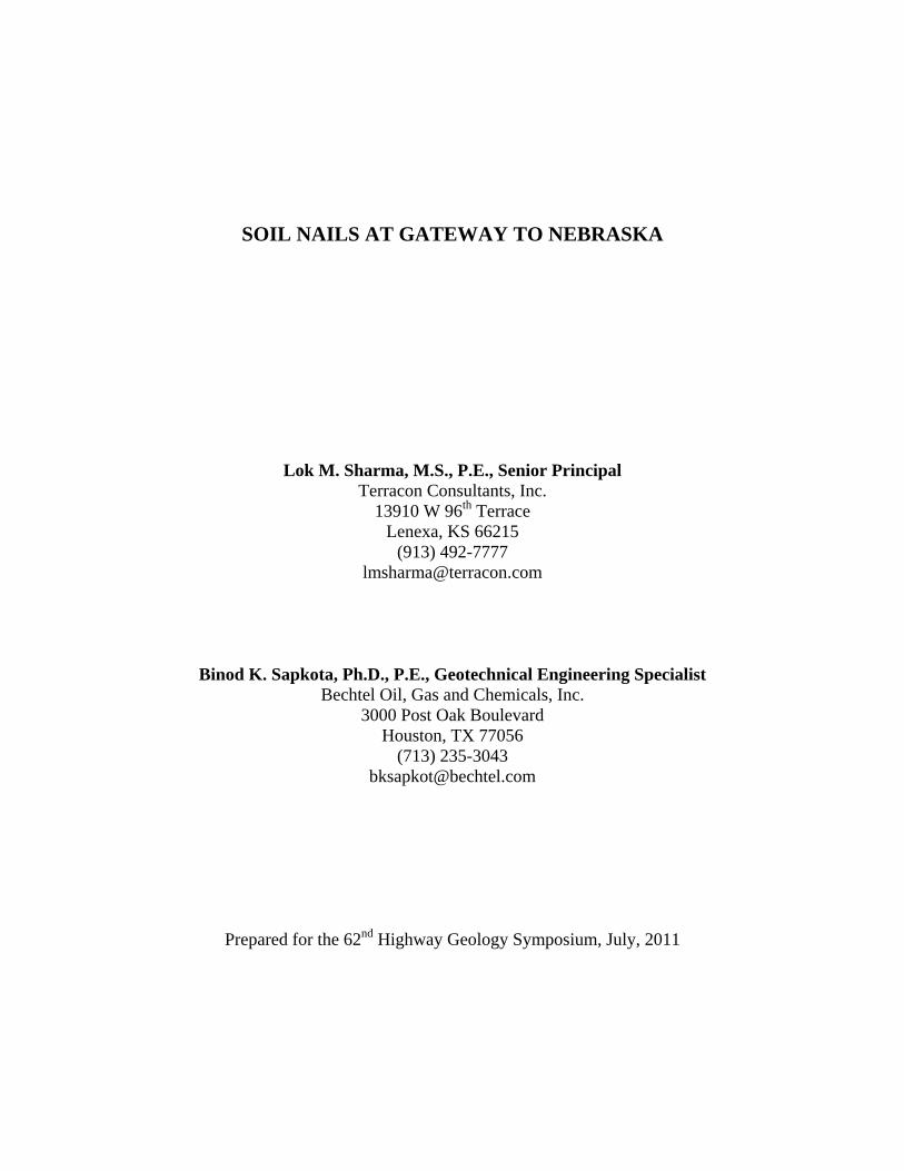
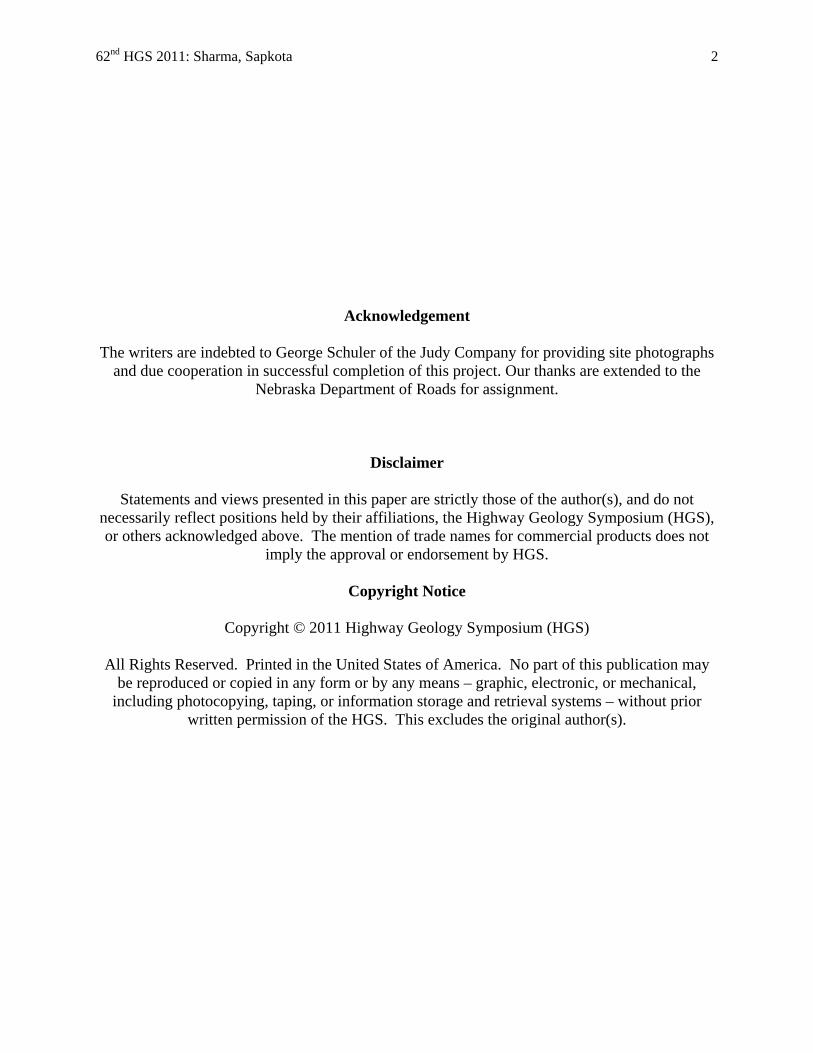
Figure 3 – FLAC Analysis of Existing Slope For stability analysis of Upper Wall 6: considered 4 rows of soil nails at 4.5 vertical and 5 foot horizontal spacing. Figures 4 and 5 present the analysis results. Figure 5 presents the results of axial tension on the soil nails computed by FLAC. Similar analyses were performed for walls 5 and 4. Results are shown in Figures 6, 7, 8, 9 and 10. The figures also show assumed groundwater levels and distribution of finite difference zones (grid). In the model the vertical sides (at ends) were considered to be fixed against x-displacements and free in y-displacements. The base of the finite difference model was considered free in x-displacements and fixed in y-displacements.
62nd HGS 2011: Sharma, Sapkota 8
Figure 4 – Wall 6
Figure 5 – Wall 6

62nd HGS 2011: Sharma, Sapkota 9
Figure 6 – Wall 5 and 6
Figure 7 – Walls 5 and 6

62nd HGS 2011: Sharma, Sapkota 10
Figure 8 – Walls 4, 5 and 6
Figure 9 – Walls 4, 5 and 6

62nd HGS 2011: Sharma, Sapkota 11
Figure 10 – Walls 4, 5 and 6
SNAIL ANALYSIS
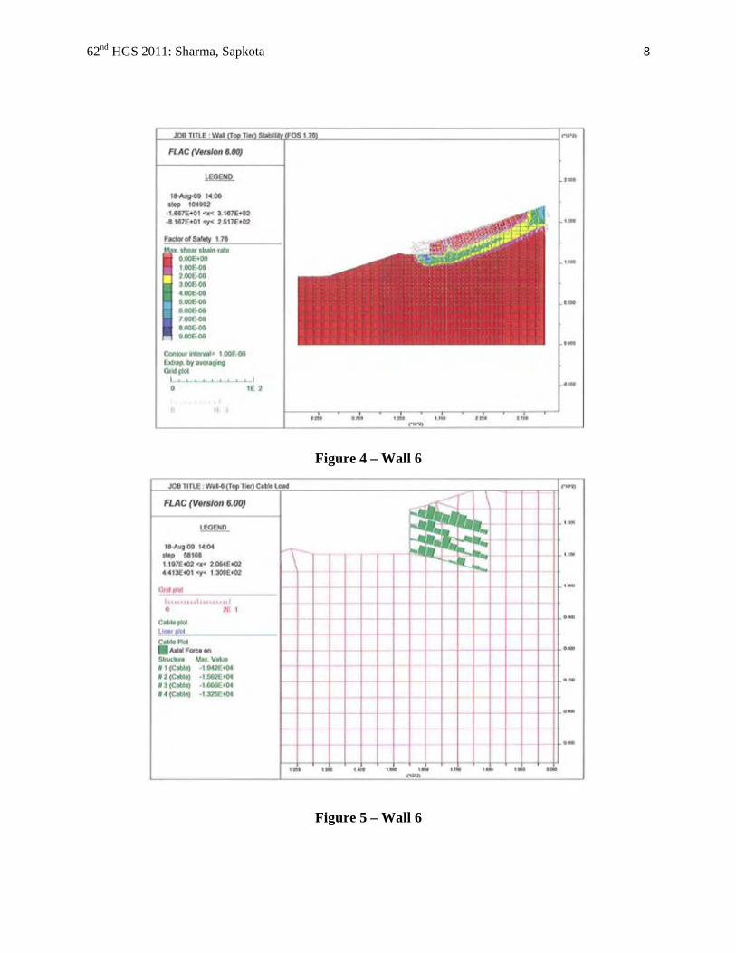
SNAIL is a computer program developed by California Transportation Department (CalTran).The program is based on two-dimensional limit equilibrium method (LEM) that considers force equilibrium only. The limit equilibrium method of slope analysis is based on the principals of statics and remains a useful tool for stability analysis. The limit equilibrium method of slope stability analysis does not satisfy displacement compatibility when the material behavior tends to be elastic-plastic. The FLAC modeling presents stresses and strain based analysis and satisfy the issue of displacement compatibility. The Windows based version of SNAIL – SNAILWIN was used in the analysis. SNAIL program allows installation of soils nails in only one wall face (that is, on one tier only). Analysis of the upper single tier is thus permissible; however, for lower tiers, the back slope above the walls was modified to represent a surcharge on the lower walls. Figures 11, 12, and 13 present the representative cross-sections adopted for SNAIL.

62nd HGS 2011: Sharma, Sapkota 12
Figure 11 – Wall 6, SNAIL Analysis
Figure 12 – Wall 5, SNAIL Analysis
62nd HGS 2011: Sharma, Sapkota 13
Figure 13 – Wall 4, SNAIL Analysis
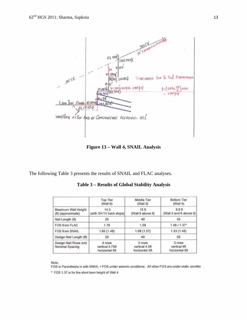
The following Table 3 presents the results of SNAIL and FLAC analyses.
Table 3 – Results of Global Stability Analysis

62nd HGS 2011: Sharma, Sapkota 14
EXTERNAL STABILITY OF SOIL NAIL BLOCK
The external stability of the soil nail wall involves sliding, overturning and bearing capacity check. Figure 14, 15 and 16 show the configurations used in the external stability analysis for static and seismic conditions. For seismic stability Mononobe-Okabe Equation was used to compute pressures. All computed FOSs were acceptable.
Figure 14 – External Stability – Wall 6
Figure 15 – External Stability – Walls 5 and 6

62nd HGS 2011: Sharma, Sapkota 15
Figure 16 – External Stability – Walls 4, 5 and 6 CONSTRUCTION The construction of walls was preceded by a number of proof and verification tests. All proof test nails were sacrificial. Verification tests were performed on selected production nails. Extensive testing was justified due to variability in soil conditions. At one location of the wall an old trash dump was encountered (Photograph 1). Excavation of the trash and replacement with well compacted soil was implemented. Proof tests of nails were performed through the backfill soil areas. The construction followed the normal procedures for soil nail wall construction in a top down manner, excavating in stages for each level of soil nail, applying the construction shotcrete facing and then proceed to the next level. The loess deposit was generally a stiff to very stiff material with dense structure. Photographs 2, 3, 4 and 5 show the construction work in progress. Photo 1 Photo 2

62nd HGS 2011: Sharma, Sapkota 16
Photo 3 Photo 4
Photo 5
Due to high visibility, the upper and the bottom tiers surfaces were provided with recessed notches in the wall for aesthetics. Also the facing of the wall was finished with a shotcrete-in-place and carved and stained surface to give a bedrock appearance as shown in Photographs 6, 7 and 8. Photograph 9 shows an overall appearance of the three tiered soil nail wall.
Photo 6 Photo 7

62nd HGS 2011: Sharma, Sapkota 17
Photo 8 Photo 9
The soil nail walls have been constructed with surface mounted monitoring hubs. The monitoring is being performed by NDOR. The data that has been available to date indicated deformations are well within the acceptable limits. CONCLUSIONS The FLAC numerical modeling allowed a displacement based slope stability analysis, while limit equilibrium method presented the conventional analysis for global stability of a tiered retaining wall. The design procedures for a tiered Soil Nail wall are not appropriately available and simplification of design in terms of considering the upper walls as surcharge on the lower wall appeared to have provided adequate design of the soil nail wall at this site. The FHWA soil nail design methodology for the soil nails and the facing design is found to be appropriate. With the co-operation of the site contractors and the NDOR, a well designed wall with extensive analysis has been constructed. The wall has presented itself as the most economical solution for this site. With the high visibility, the appearance of the wall blends well. The wall has become a showcase project due to its vicinity to the urban environment.

62nd HGS 2011: Sharma, Sapkota 18
REFERENCES:
Federal Highway Administration (2003) “Geotechnical Engineering Circular No. 7, Soil Nail
Walls”, FHWA 0-IF-03-017, Carlos A. Lazarate, Victor Elias, R. David Espinoza, Paul J. Sabatini
Fast Lagrangian Analysis of Continua (FLAC) ver. 6.0, Itasca Consulting Group, Inc.
Terracon Consultants, Inc., Design report of Soil Nail Walls, I-80 Missouri River to 13th Street, Omaha, NE, August 2009.