soil water reservoir - ucanr
TRANSCRIPT

Soil Water ReservoirSoil Water Reservoir
Soil TextureSoil TextureSoil StructureSoil StructureRootzoneRootzone DepthDepthInfiltrated RainfallInfiltrated Rainfall
Volume and seasonal distributionVolume and seasonal distribution

Soil TextureSoil Texture
Relative proportions Relative proportions ofof
different particle sizesdifferent particle sizes
Sand Sand -- Silt Silt -- ClayClay

Soil TextureSoil Texture


Rooting Depth LimitationsRooting Depth Limitations
Fine texture with poor internal drainageFine texture with poor internal drainageDense, compact, or cemented Dense, compact, or cemented subsoilssubsoilsLayered or stratified soil with abrupt Layered or stratified soil with abrupt changechange
RockRockWater tableWater table

RootstocksRootstocks
Shallow rooting natureShallow rooting nature5C, 5BB, 11035C, 5BB, 1103

Determine Depth Using:Determine Depth Using:
BackhoeBackhoeAugerAuger
If wet in spring and
Dry in fall --

RootzoneRootzone Water Holding CapacityWater Holding Capacity
Water holding capacity X Water holding capacity X RootzoneRootzone DepthDepth
Ex. Clay Loam = 1.6 in/ft Available waterEx. Clay Loam = 1.6 in/ft Available waterRootzoneRootzone Depth = 5 ftDepth = 5 ft
1.6 X 5 = 8.0 inches of available water1.6 X 5 = 8.0 inches of available water

Figure B-2. Winegrape non-irrigated in/ft by depth
0.000.200.400.600.801.001.201.401.601.80
Date
Tot
al W
ater
(in/
hr) 9"
21" 33" 45" 57" 69" 82" 94" 106"
Using Neutron Probe DataUsing Neutron Probe Data

Measuring Water SourcesMeasuring Water Sources
Soil moistureSoil moistureInIn--season Rainfallseason RainfallIrrigation WaterIrrigation Water

Volume UnitsVolume Units
RainfallRainfall inches/depthinches/depthCrop Water UseCrop Water Use inches/depthinches/depthSoil moistureSoil moisture inches/depthinches/depth
% = in / in % = in / in % x 12 inches = % x 12 inches = inchesinches / foot soil/ foot soil% x % x rootzonerootzone depth = inches water in depth = inches water in rootzonerootzone

Soil Constituents by VolumeSoil Constituents by VolumeAt field capacityAt field capacity
Mineral50%
Air 25%
Water 25%
Organic matter <1%

Available Soil MoistureAvailable Soil Moisture
Moisture contained in the soil which vines Moisture contained in the soil which vines can removecan removeAll available moisture is not equally All available moisture is not equally availableavailable


Available Soil MoistureAvailable Soil Moisture
Field Capacity Field Capacity –– Perm wilt pointPerm wilt point
Field CapacityField CapacityUpper limit when drainage ceasesUpper limit when drainage ceases
Permanent Wilting pointPermanent Wilting pointLower limit when plants cannot extract moistureLower limit when plants cannot extract moisture

Table C-1. Soil moisture content in inches of water per foot of soil at field capacity, 15 bars, and available soil moisture
for various soil textures.
Soil Texture Field Capacity 15 Bars Available Moisture Content
Sand 1.2 0.5 0.7 Loamy Sand 1.9 0.8 1.1 Sandy Loam 2.5 1.1 1.4 Loam 3.2 1.4 1.8 Silt Loam 3.6 1.8 1.8 Sandy Clay Loam 3.5 2.2 1.3 Sandy Clay 3.4 1.8 1.6 Clay Loam 3.8 2.2 1.6 Silty Clay Loam 4.3 2.4 1.9 Silty Clay 4.8 2.4 2.4 Clay 4.8 2.6 2.2

Soil Water MeasuresSoil Water Measures
Soil Water ContentSoil Water ContentQuantitative Quantitative
Percent water by weight or volumePercent water by weight or volume
Soil Moisture Status or TensionSoil Moisture Status or TensionQualitativeQualitative
Centibars of TensionCentibars of Tension
Moisture StatusMoisture Status
TensiometersTensiometersGypsum BlocksGypsum Blocks

Tensiometer
10050
Vacuum Gauge
Porous Ceramic Cup
Reservoir
Cap
Water
0 – 80 Centibars


Tension versus soil moisture content for two soil textures.
Soil Moisture Content (%)
0 5 10 15 20 25 30 35 40 45
0
20
40
60
80
100
Silty Clay
Sandy Loam
TensiometerReading (centibars)


Gypsum Block
55
Electrical Resistance Block Instrument
Wire
Display


Soil Moisture Content (%)0 10 20 30 40 50
Gyp
sum
Blo
ck R
eadi
ng
0
20
40
60
80
100
Sandy LoamSilty Clay

IrrometerIrrometer Watermark Sensor/MeterWatermark Sensor/Meter

Soil Moisture Content (%)0 5 10 15 20 25 30 35 40Wat
erm
ark
Blo
ck R
eadi
ng (c
entib
ars)
020406080
100120140160180200
Sandy LoamSilty Clay

Soil Water ContentSoil Water ContentDirect / Indirect MethodsDirect / Indirect Methods
DirectDirectSoil sampling by volumeSoil sampling by volume
OrOr------ by weight x soil bulk densityby weight x soil bulk density
IndirectIndirectany method which relates a any method which relates a ““readingreading”” to soil to soil sampling moisture contentsampling moisture content

Indirect MethodsIndirect Methods
Soil DielectricSoil DielectricTime Domain Reflectometry (TDR)Time Domain Reflectometry (TDR)Ground Penetrating Radar (GPR)Ground Penetrating Radar (GPR)Frequency Domain Reflectometry (FDR Frequency Domain Reflectometry (FDR or capacitance)or capacitance)
Neutron ScatterNeutron Scatter

Soil DielectricSoil Dielectric
The dielectric permittivity is a measure of the The dielectric permittivity is a measure of the capacity of a noncapacity of a non--conducting material to conducting material to transmit electromagnetic waves or pulses.transmit electromagnetic waves or pulses.
Dielectric Permittivity Dielectric Permittivity Air = 1 Air = 1 soil minerals = 3 to 5soil minerals = 3 to 5
(denser soils have higher apparent (denser soils have higher apparent permittivitiespermittivities). ).
Water 81Water 81

Influencing Factors Influencing Factors
Water Content Water Content Soil TemperatureSoil TemperatureSoil Porosity and Bulk DensitySoil Porosity and Bulk DensityMinerals (clay)Minerals (clay)Measurement FrequencyMeasurement FrequencyAir GapsAir Gaps

Time Domain Reflectometry Time Domain Reflectometry (TDR)(TDR)
Based on the propagation velocity of Based on the propagation velocity of electromagnetic wave traveling along a electromagnetic wave traveling along a probe placed in the soil (non conducting probe placed in the soil (non conducting media)media)
Water is the Water is the principalprincipal factor affecting a factor affecting a TDR signal (measurement a 1 TDR signal (measurement a 1 GhzGhz))

TDRTDR

TDR AdvantagesTDR Advantages
PrecisePreciseAccurateAccurateVersatile packaging: from portable, selfVersatile packaging: from portable, self--contained contained units to modular systems capable of monitoring units to modular systems capable of monitoring several probes and logging dataseveral probes and logging dataLack of radiation hazard associated with neutron Lack of radiation hazard associated with neutron probe probe Calibration requirements are minimalCalibration requirements are minimal——in many in many cases soilcases soil--specific calibration is not needed specific calibration is not needed

TDR DisadvantagesTDR Disadvantages
Relatively expensiveRelatively expensiveSmall measuring volumeSmall measuring volumeShallow measurements or buried probeShallow measurements or buried probeConductive soils may lead to Conductive soils may lead to inaccuraciesinaccuraciesShort cable lengths are necessary due Short cable lengths are necessary due signal attenuationsignal attenuation

Water Content Water Content ReflectometerReflectometer
CS 661-L
Similar to TDR Lower frequencyWave storage electronics / software not necessaryUses data logger to store dataMore sensitive to Temp, Density, and ClayCalibration generally required
Cables up to 1000 ftLess expensive

Ground Penetrating RadarGround Penetrating Radar(GPR)(GPR)
RF bursts are emitted and the reflected RF bursts are emitted and the reflected wave is captured and frequency wave is captured and frequency measuredmeasuredSimilar to TDR but the wave is not Similar to TDR but the wave is not boundbound

GPRGPR(CNN) (CNN) ---- Grapes and geophysicsGrapes and geophysics
Dry soil produces better red wine grapes;Dry soil produces better red wine grapes;Moister soil makes white wine grapes thrive. Moister soil makes white wine grapes thrive.

GPRGPR
Variations in soil texture (clay), crop cover, Variations in soil texture (clay), crop cover, salinity, and irrigation practices result in salinity, and irrigation practices result in large variability in soil moisturelarge variability in soil moistureThe depth of influence is a function of soil The depth of influence is a function of soil type, moisture content and GPR antenna type, moisture content and GPR antenna frequency Limited to a few feet in dry clay frequency Limited to a few feet in dry clay soilsoil–– less in moist soilless in moist soil

GPR AdvantagesGPR Advantages
RapidRapidNonNon--invasiveinvasiveVery high spatial data densityVery high spatial data densityPrinciples of operation almost identical to Principles of operation almost identical to TDR but at a lower frequencyTDR but at a lower frequency
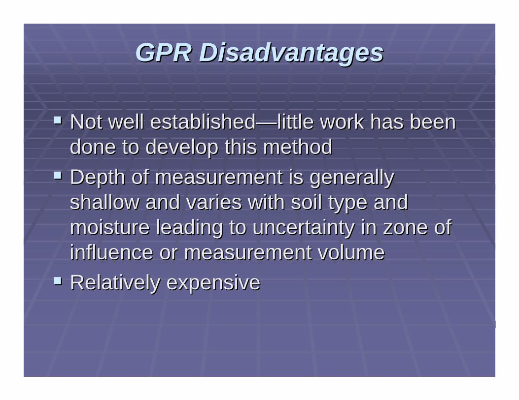
GPR DisadvantagesGPR Disadvantages
Not well establishedNot well established——little work has been little work has been done to develop this methoddone to develop this methodDepth of measurement is generally Depth of measurement is generally shallow and varies with soil type and shallow and varies with soil type and moisture leading to uncertainty in zone of moisture leading to uncertainty in zone of influence or measurement volumeinfluence or measurement volumeRelatively expensiveRelatively expensive

Frequency Domain/CapacitanceFrequency Domain/Capacitance
A couple different methods are used A couple different methods are used however, they all use:however, they all use:
Electronic circuit in which the two plates, Electronic circuit in which the two plates, rods or rings use the soil between them as rods or rings use the soil between them as dielectric of a capacitordielectric of a capacitor
The change in the circuit output is The change in the circuit output is related to the dielectric permittivityrelated to the dielectric permittivity

Electrode
Access Tube
Data Logger
Solar Panel
Cable
Electrode
Ground Surface
Permanent/loggingMulti depth
Single point measurePortable

FDRFDR
Soil specific calibration curves are Soil specific calibration curves are needed for soils that are highly needed for soils that are highly conductive, have high organic content, conductive, have high organic content, or contain 2:1 clays or contain 2:1 clays

Vol
umet
ric W
ater
Con
tent
0.8 1.0 1.2 1.4 1.6 1.8 2.0 2.2
Period (msec)
0.4
0.3
0.2
0.1
0.0
0.6
After Kim and Benson 2002
Soil Specific CalibrationSoil Specific Calibration

Silt Loam
FDRFDR

C-Probe
0
10
20
30
40
50
60
70
80
90
12/9 12/14 12/19 12/24 12/29 1/3 1/8
Soil
Moi
stur
e
0.0
0.5
1.0
1.5
2.0
2.5
3.0
3.5
4.0
Rai
nfal
l (in
)
Rainfall 36 in 24 in 48 in

C-Probe
25.0
30.0
35.0
40.0
45.0
50.0
55.0
60.0
65.0
70.0
75.0
6/13 6/20 6/27 7/4 7/11
Moi
stur
e
12in 24 in 36 in 48 in 60 in
Irr = 1.4 in

FDR AdvantagesFDR Advantages
Relatively inexpensiveRelatively inexpensivelow frequency standard circuitrylow frequency standard circuitry
No radiation hazard / hassles No radiation hazard / hassles Fast response timeFast response timeLogging capableLogging capablePortablePortable

FDR DisadvantagesFDR Disadvantages
Small measurement volume sensitive to Small measurement volume sensitive to smallsmall--scale soil variations (most in 5mm)scale soil variations (most in 5mm)Sensitivity to installation similar to TDR Sensitivity to installation similar to TDR Site specific calibration is necessary for Site specific calibration is necessary for accurate soil volumetric water contentaccurate soil volumetric water contentTends to have larger sensitivity to salinity, Tends to have larger sensitivity to salinity, temperature, bulk density, clay content temperature, bulk density, clay content and air gaps than TDR and air gaps than TDR

15324
Access Tube
Source TubeD etec tor
Radioactive Source
C able
Instrument and Protective Shielding
Cable
Ground Surface
Display
Neutron Scatter / ProbeNeutron Scatter / Probe
Wet
Dry


NP Field CalibrationNP Field Calibration2004 Syrah N Probe Calibration
y = 3.7801x - 1.5938R2 = 0.9115
0
0.5
1
1.5
2
2.5
3
3.5
4
4.5
0 0.2 0.4 0.6 0.8 1 1.2 1.4 1.6
Count Ratio (RO)
Volu
met
ric S
oil W
ater
Con
tent
(in/
ft)

CalibrationCalibration
DownDown--hole samplers are pushed into the soil at the bottom of hole samplers are pushed into the soil at the bottom of an an augeredaugered hole to take fixed volumetric (60 cc) sampleshole to take fixed volumetric (60 cc) samples
Device readings are taken at the same depths immediately Device readings are taken at the same depths immediately after sampling after sampling
Samples are oven driedSamples are oven dried
Percent water content Percent water content vsvs readingreading

NP AdvantagesNP Advantages
Large measurement volume produces high Large measurement volume produces high precisionprecisionWorks well in stony soils and expansive Works well in stony soils and expansive claysclaysVery accurate, when calibratedVery accurate, when calibratedAir gaps and soil disturbance during access Air gaps and soil disturbance during access tube installation has minimal effects tube installation has minimal effects Multiple point measurementsMultiple point measurements

NP DisadvantagesNP Disadvantages
CostlyCostlyCannot be automated because Cannot be automated because radioactive source may not be left radioactive source may not be left unattendedunattendedCost of regulation and licensing of a Cost of regulation and licensing of a radioactive source/ and disposal costradioactive source/ and disposal costSurface measurements inaccurate < 9 Surface measurements inaccurate < 9 ininHeavy awkward device Heavy awkward device Time required for readingTime required for reading

Soil and Water Holding / Supplying Soil and Water Holding / Supplying VariabilityVariability
Variability within the vines root zone and Variability within the vines root zone and on a field scale is the largest error when on a field scale is the largest error when trying to approximate the mean soil trying to approximate the mean soil moisturemoisture
Soil VariabilitySoil VariabilityTextureTextureDensityDensityRoot limiting conditionsRoot limiting conditionsVine water extractionVine water extraction

Solution to VariabilitySolution to Variability
More measurement pointsMore measurement points
Based on:Based on:Level of confidence needed Level of confidence needed ieie. 95%. 95%Variability that exists Variability that exists Mean Value expectedMean Value expected

Power Curvealpha = 0.05, sigma = 1.52, n=4
True Mean
Pow
er
3.5 5.5 7.5 9.5 11.50
0.2
0.4
0.6
0.8
1
Number of SitesNumber of Sites
Mean = 6.59Sdev = 1.52

Data Handling / TelemetryData Handling / Telemetry
Wide range availableWide range available
Direct hand held Direct hand held ““podpod”” collectioncollectionCell phone modem to Cell phone modem to
data processing todata processing tointernet accessinternet access

SummarySummary
Volumetric Water ContentVolumetric Water ContentDielectric MethodsDielectric MethodsNuclear MethodsNuclear Methods
All require field calibration if volumetric All require field calibration if volumetric requiredrequiredDielectric Dielectric
Can be automated / unattended / transmittedCan be automated / unattended / transmittedGenerally inexpensiveGenerally inexpensiveNeed a number of sites/depths to characterize the Need a number of sites/depths to characterize the rootzonerootzone and fieldand field

Looking AheadLooking Ahead
Increased use of devices which can log Increased use of devices which can log transmit and allow automatic data transmit and allow automatic data processing. processing. ------ Dielectric methodsDielectric methods
The Neutron Probe is the standard and will The Neutron Probe is the standard and will be slow to replace by virtue of its be slow to replace by virtue of its advantagesadvantages

Sensor Area of MeasureSensor Area of Measure
Most sensors read a small areaMost sensors read a small areaTensiometers and Gypsum BlocksTensiometers and Gypsum Blocks
Smallest areaSmallest area–– a few cubic centimetersa few cubic centimeters
Dielectric methods Dielectric methods Narrow disk shaped measurement area a few cm Narrow disk shaped measurement area a few cm outside the well or from thee waveguidesoutside the well or from thee waveguides
Neutron ProbeNeutron ProbeLargest area Largest area –– a few inches in radius of the a few inches in radius of the detectordetector

Sensor PlacementSensor Placement
Depends on the goal of the measurementDepends on the goal of the measurement
If measuring soil water depletion before If measuring soil water depletion before irrigationirrigation------ not too importantnot too importantIf measuring after irrigationIf measuring after irrigation–– proximity to proximity to the emitter will effect the readingthe emitter will effect the reading


When To Measure Soil MoistureWhen To Measure Soil MoistureQuantitative( N Probe)Quantitative( N Probe)
Most valuable times:Most valuable times:Bud breakBud breakJust prior to 1st irrigation Just prior to 1st irrigation Dry pointDry point
Bud break Bud break –– Dry Point = Available waterDry Point = Available waterBud break Bud break –– Prior to 1Prior to 1stst irrirr = Water consumed= Water consumedPrior to 1Prior to 1stst irrirr –– Dry Point = water remainingDry Point = water remaining

Measuring Effective InMeasuring Effective In--Season RainfallSeason Rainfall
Effective Rainfall = [rainfall (in) Effective Rainfall = [rainfall (in) -- 0.25 in] 0.25 in] ×× 0.80.8
Table C-3. Effective rainfall
Day Rainfall (inches)
Effective Rainfall (inches)
1 0.39 0.11 2 0.62 0.30 3 0 0 4 0 0 5 0 0 6 0 0 7 0.25 0
Weekly Total 1.26 0.41
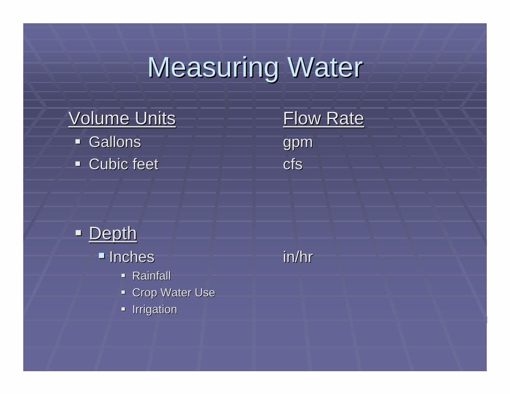
Measuring WaterMeasuring Water
Volume UnitsVolume Units Flow RateFlow RateGallonsGallons gpmgpmCubic feetCubic feet cfscfs
DepthDepthInches Inches in/hrin/hr
RainfallRainfallCrop Water UseCrop Water UseIrrigationIrrigation

Measuring Irrigation WaterMeasuring Irrigation Water
FlowmetersFlowmetersEmitter DischargeEmitter Discharge

Totalizing Water MeterTotalizing Water Meter

Proper Water Meter InstallationProper Water Meter Installation
Meter
Flow
Min 10 x pipe dia.Min 1 pipe dia.
8 in pipe = 80 in

Doppler Water MeterDoppler Water MeterPortable totalizing and instantaneous readings 2” to 9 ft dia.
Sensor
pipe cross-sectional area X water velocity = Flow rate

Discharge MethodDischarge Method
Measure the flow rate at the discharge pointMeasure the flow rate at the discharge point

Orchard / Vineyard PotsOrchard / Vineyard Pots

Emitters
½ or 1 gph at nominal pressure

Emitter discharge Emitter discharge vsvs pressurepressure
1
15

Emitters:Emitters:
PressurePressure--compensating compensating emitters are available.emitters are available.
Particularly good where you Particularly good where you have significant elevation have significant elevation changes.changes.
2.31 ft. of elevation change = 1 2.31 ft. of elevation change = 1 psipsi


Measuring Micro Irrigation Measuring Micro Irrigation Discharge RateDischarge Rate

Micro system discharge rate Micro system discharge rate
Volume of water collected (ml) in 30 sec X 0.0317 Volume of water collected (ml) in 30 sec X 0.0317 = Discharge rate (= Discharge rate (gphgph))

Average discharge rate Average discharge rate to applied inchesto applied inches
Ave. Discharge RateAve. Discharge Rate ((gphgph) x ) x no. discharge devices per plant /no. discharge devices per plant /plant spacing (sq ft) x 1.6 =plant spacing (sq ft) x 1.6 =aveave. application rate (in/hr). application rate (in/hr)
Applied WaterApplied Waterin/hr x hrs of operation = applied inchesin/hr x hrs of operation = applied inches

Average discharge rate Average discharge rate to applied inchesto applied inches
Ave. Discharge RateAve. Discharge Rategphgph) x no. discharge devices per plant /) x no. discharge devices per plant /plant spacing (sq ft) x 1.6 =plant spacing (sq ft) x 1.6 =aveave. application rate (in/hr). application rate (in/hr)
0.5 0.5 gphgph x 2 emitter/plant / 7x10 ft x 1.6 = 0.0229 in /hrx 2 emitter/plant / 7x10 ft x 1.6 = 0.0229 in /hr
Applied WaterApplied Waterin/hr x hrs of operation = applied inchesin/hr x hrs of operation = applied inches
0.0229 in/hr x 24 hrs = 0.52 in0.0229 in/hr x 24 hrs = 0.52 in

Applied inches to Gallons per vineApplied inches to Gallons per vine
0.52 inches X 27158 / vines/acre0.52 inches X 27158 / vines/acreFor a spacing of 7 x11 ft = 566 vines/acreFor a spacing of 7 x11 ft = 566 vines/acre
0.52 x 27158 / 566 = 25 gal/vine0.52 x 27158 / 566 = 25 gal/vine