solar access zoning + building information...
TRANSCRIPT

1
SOLAR ACCESS ZONING + BUILDING INFORMATION MODELING
Karen Kensek Alicyn Henkhaus
University of Southern California School of Architecture, Watt Hall #204
Los Angeles, CA 90089-0291 [email protected]
ABSTRACT
Access to sunlight for day lighting or solar power on a site can be jeopardized by the decisions of architects designing for neighboring sites. Solar access zoning is one method for ensuring that future buildings do not shade their neighbors for a specified time period each day. A solar envelope represents the largest volume that satisfies the conditions of solar access for the building’s neighbors. The geometry of the solar envelope depends both on spatial relationships between the sites and the sun’s path. Methods of creation have included hand calculations, cardboard models, and computer tools. With the rising popularity of building information modeling (BIM), it was decided that a new digital tool would be helpful for architects to use within the BIM software to integrate the analysis and use of solar envelopes in design. A solar envelope plug-in for Revit Architecture (written in C# with the Revit API) was developed.
1. INTRODUCTION
Sunlight is a resource that architects can choose to incorporate into their designs, for passive strategies like day lighting or active technologies like photovoltaics. However, continued access to the sun is often affected by the decisions of other architects building on neighboring sites. In order for a designer to take full advantage of the resources provided by the sun and reap the benefits of energy conservation, some protection of solar access on the site must be ensured over the lifetime of the building.
Within the American legal system there are three avenues that could provide for the allocation and protection of solar rights: express agreements (contracts) between landowners, government-backed laws (such as permit systems or zoning
ordinances), and court-assigned rights from the settlement of a case. Currently, solar rights protections vary greatly across the U.S. and are generally limited to the protection of installed solar collectors. The statutes of at least 39 states address solar access in some way. Many provide a legal framework for solar access rights, and a few actually protect solar access rights [1,2].
Most of the states that protect solar access rights use a permit system: by default no protections are in place, but a property owner may apply for solar access protections. Some advocates of solar access rights prefer a system where the default case provides protection to all lots [3]. This can be achieved through a zoning ordinance, and there are a number of U.S. cities that protect the access of direct sunlight to properties through zoning [4-7]. One type of zoning ordinance uses variable setback and height restrictions to limit the shadow cast by a building. Generally, a few equations and tables are used to determine the exact setback and height for a lot. The equations may account for the lot’s dimensions, orientation, and slope. Another type of zoning ordinance indirectly limits building height by restricting shadow length. This generally requires a shadow analysis for a specified day or days, usually the winter solstice, and times of day.
These two methods seek to protect the solar access of all properties in the zone. Instead of navigating tables based on site geometry or a shadow analysis, imagine a zoning ordinance based on the principle that a building could not shade its neighbors for a specified time period each day. This concept was proposed by Ralph Knowles and defines a solar envelope: the largest volume on a site that satisfies the conditions of solar access for the building’s neighbors. For example, one might restrict the shadows cast by the building to not infringe on neighboring sites from 8 am – 4 pm on the summer solstice. This does not imply that a building within

2
the envelope’s spatial limitations is an energy-efficient design or that its neighbors would be either. Rather, when applied to adjacent lots, solar access zoning guarantees that each lot receives enough sunlight to take advantage of passive and active solar design strategies. It is a zoning tool, not a method for applying to single lots.
The increased power of computers and access to computer-aided design (CAD) tools has made it possible to create a solar envelope generator that is housed within a building information modeling (BIM) program. Designers may find it easier to generate a solar envelope once and use the dimensions to design a building, rather than going through iterations of designing a building, comparing the shadow analysis to a zoning ordinance, and making adjustments to the building.
This paper will focus on the design and capabilities of a BIM integrated solar envelope generator.
2. THE SOLAR ENVELOPE TOOL
The geometry of a solar envelope is relatively difficult to calculate; it depends both on spatial relationships between the site and its neighbors and on the daily and seasonal path of the sun. Solar envelopes can be constructed as physical models with some math and a heliodon or generated by various digital tools. Solar envelope generators have been developed as stand-alone programs, web-based applications, and integrated with 3d modeling programs. Each tool reflected the current technology of the time, and the progression of modeling environments has made many obsolete.
Developing the solar envelope generator as an add-in to an existing modeling program has many benefits for both the developer and the ultimate user. Add-ins take advantage of the user interface (UI) and application programming interface (API) of the host program, so a developer can access all of the functionality of the existing program without recreating code from scratch. The new functions provided by an add-in are more accessible to users because they are based on a UI and modeling environment that they are already familiar with.
There are three main techniques for using computers to generate solar envelopes. The “grid and flag pole” is a numerical method that works only for concave sites and generates an approximation of the true solar envelope based on a grid of points. The method of cutting solids is an analytical method that successively eliminates volume from a basic site extrusion until the true solar envelope remains. Programs that are capable of performing Boolean intersections on solids can use a third method based on that
operation to generate solar envelopes for any site that is defined by a closed loop.
2.1. Algorithm
The tool discussed in this paper uses a method of cutting solids, in which volumes that would result in shaded neighbors are successively cut away from an extrusion of the site boundary or envelope base, revealing the solar envelope. This is a fairly robust method that can accommodate any polygonal site. With the right 3d solid modeling program, it could even be used to incorporate site topography [8]. Cutting away from a base extrusion allows the most flexibility for generating an envelope based on solar access and/or fence height restrictions that are not uniform across the site. Fence height restrictions refer to the concept that one could choose to allow shadows up to a certain height on neighboring sites; for example, for mixed use developments, shading the ground floor up to about 10’ might be acceptable while still protecting solar access for residences on the upper floors.
This tool’s initial user input includes information about the site and the solar access requirements. A dialog window is used for numerical input (Fig. 1). The geometry of the site boundary is input by selecting reference points placed at each vertex of the site (Fig. 2).
Fig. 1: Solar envelope input window.
The numerical inputs include the site latitude, the maximum building height allowed, and a fence height. The fence height represents the height at which shade would be allowed on a fence at the shading boundary line. The two solar access requirements represent the amount of time that solar access is protected on the summer and winter solstices. There is also an option to reuse the site boundary as the

3
shading boundary or to select a separate shading boundary. The shading boundary may be different from the site’s boundary if a building is allowed to shade the sidewalk and street in front of it.
Fig. 2: Vertices of the site geometry, input from the modeling environment.
After the user has completed the data input and selected points for the site and shading boundaries, the tool can generate the solar envelope. The general algorithm for the cutting planes technique used is shown in Fig. 3, but first the relevant solar angles must be calculated from the user inputs. The site latitude and duration of solar access requirements are used to calculate the position of the sun (altitude and azimuth angles) for the times when protected solar access begins and ends on the two solstices, using equations from [9]. The altitude and azimuth angles are converted to 3d vectors for ease of calculation.
Fig. 3: Process from solar access constraints to cutting boxes.
The algorithm used by this tool (Fig. 3) creates a set of cutting planes based on two sets of vectors: the set of vectors representing sun position at the solar access constraints, and the set of vectors that define the geometry of the site and shading boundaries. The first step is an
extrusion of the planar site boundary, which is a polygon. Then for each solar access constraint, the solar vector is placed at each vertex of the site boundary. A plane is then constructed with each segment of the site boundary and the vectors at the adjacent vertices (Fig. 4). This solar plane forms the base of a new extrusion, which is cut away from the current version of the site extrusion.
Fig. 4: Altitude and azimuth (α and θ) define a solar vector (vsolar). The solar plane (S) is defined by the solar vector and a site vector (vn).
Eventually a volume with a multi-faceted “roof,” the solar envelope, will remain (Fig. 5).
Fig. 5: Plan (left) and perspective (right) views of a solar envelope.
2.2. Solar Envelope Variables
The constraints of a typical solar envelope dictate that the building cannot cast shadows on its neighbors during the agreed upon hours. However, in some cases it may be acceptable, or even desirable, to shade neighbors up to a certain height. For example: in a retail district, shop owners may prefer to have shaded storefronts to protect their merchandise from the light or heat of the sun. In a residential neighborhood, many properties are surrounded by fences, which will cast shadows of their own, so it is also acceptable to shade one’s neighbor up to the top of her fence. The height of such a “shadow fence” can be entered on the initial input screen. As fence height varies the “roof” of the solar envelope remains the same, but the maximum height increases and decreases accordingly (Fig. 6).
SOLAR ACCESS CONSTRAINTS SITE BOUNDARIES
R1 R
2 R
3 T
4
T4R
3R
2R
1
composite transform
intermediate transforms
(n × m) transforms (n × m) cutting solids
loop n times loop m times
N

4
Fig. 6: Elevation view of a solar envelope with a shadow fence.
While the site boundary defines the limits of the solar envelope at ground level, the shading boundary has a larger effect on the overall geometry of the envelope. This can be seen in Fig. 7. Both envelopes are constructed from the same site boundary. For the envelope on the left, the site and shading boundary are the same. For the envelope on the right, the shading boundary is drawn outside the site boundary and in a different shape. The edges and the slopes of the faces are completely different for the two envelopes. The two envelopes in Fig. 7 also show how easily solar envelopes can be generated by computer for complex geometries, which might not be impossible but would certainly be tedious to construct by hand.
Fig. 7: Solar envelope with collinear site and shading boundaries (left) and with two separate boundaries (right).
Maximum building height is included as an input because a zoning ordinance might require both solar envelopes and an ultimate height restriction. In the cases where solar envelopes exceed the maximum allowed height, the final envelope is truncated accordingly (Fig. 8).
Fig. 8: A solar envelope where the height of the true envelope exceeds the input maximum building height. Left: perspective from the top. Right: east elevation.
2.3. Validation
The tool was validated by comparison with hand calculations (using trigonometry and similar triangles) and
solar envelopes generated by other sources. One example is shown below, with inputs in TABLE 1. Inputs were taken from an example in Sun Rhythm Form [3, p. 80].
TABLE 1: VALIDATION EXAMPLE VARIABLES
North-south length 105’ East-west length 250’ Latitude 34 °N Summer solar access requirement 10 hours Summer solar angles* Altitude: 25°
Azimuth: 78°, 282° Winter solar access requirement 6 hours Winter solar angles* Altitude: 17.6°
Azimuth: 137°, 223° Fence height 0’ Site and shading boundaries collinear?
Yes
*Solar angles were used for hand calculations. For azimuth angles, 0° is due north and clockwise is positive.
The maximum height of the envelope given in Sun Rhythm Form was compared to the maximum height when calculated by hand and the maximum height of the envelope generated by the tool under validation. These results are shown in TABLE 2.
TABLE 2: MAXIMUM ENVELOPE HEIGHT
Sun Rhythm Form 48.5’
Hand calculations 47.7’
Computer-generated 48.5’ (48’ 6 1/16”)
The results from the hand calculations and computer-generated envelope are within 2% of the published value.
3. BIM ANALYSIS
The capabilities of the solar envelope generation tool described thus far could be accomplished in most 3d modeling environments. CAD has now gone beyond simply being a modeling or drawing tool and has evolved into BIM. There are many advantages to generating and analyzing a solar envelope within a BIM environment, though not all have been achieved with this tool. Ultimately, the integration with BIM facilitates the analysis, and hopefully use, of solar envelopes in design. By having an easy-to-use
5
program, implementation of solar envelope zoning could be more feasible as well.
The volume of a solar envelope is defined by planes that are skewed to the site ground plane. Thus height restrictions vary across the site, and the more complicated the site boundary is, the more complicated the resulting envelope will be. In a BIM program, it is possible to create the geometry of the solar envelope once and obtain both graphical and numerical information about the envelope from the single generation process. For example, it is possible to cut sections through the geometry and draw new views, set floor plates at different heights and calculate total possible floor area, calculate the pitch of the envelope roof and solar radiation on any of the surfaces, etc.
The following sections show how BIM can enhance the analysis of a solar envelope.
3.1. Annotation
Dimensions, spot elevations, and spot slopes can be added to plan, elevation, and section views.
Fig. 9: Annotation examples.
3.2. Schedules
Levels can be set and used to find the available floor area and volume. The schedule shown was created based on a floor-floor height of 10’ for the envelope shown in Fig. 8.
Fig. 10: Floor schedule, based on a 10’ floor-floor height. Level 2 indicates a height of 10’.
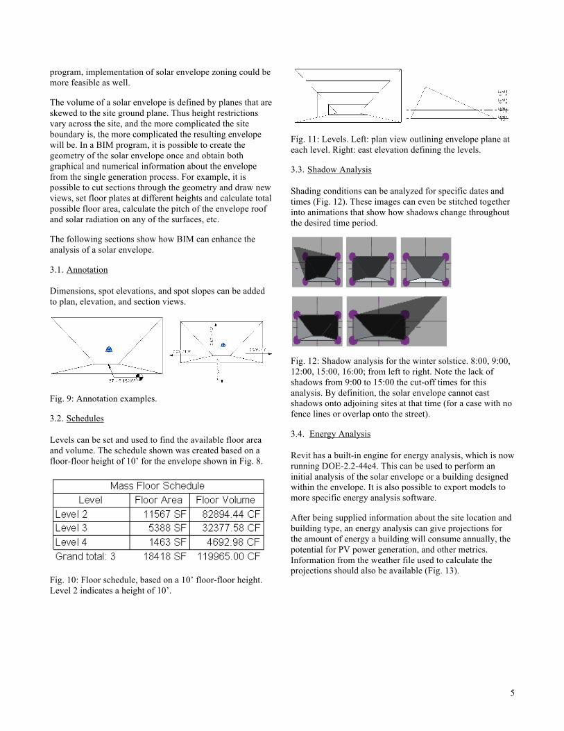
Fig. 11: Levels. Left: plan view outlining envelope plane at each level. Right: east elevation defining the levels.
3.3. Shadow Analysis
Shading conditions can be analyzed for specific dates and times (Fig. 12). These images can even be stitched together into animations that show how shadows change throughout the desired time period.
Fig. 12: Shadow analysis for the winter solstice. 8:00, 9:00, 12:00, 15:00, 16:00; from left to right. Note the lack of shadows from 9:00 to 15:00 the cut-off times for this analysis. By definition, the solar envelope cannot cast shadows onto adjoining sites at that time (for a case with no fence lines or overlap onto the street).
3.4. Energy Analysis
Revit has a built-in engine for energy analysis, which is now running DOE-2.2-44e4. This can be used to perform an initial analysis of the solar envelope or a building designed within the envelope. It is also possible to export models to more specific energy analysis software.
After being supplied information about the site location and building type, an energy analysis can give projections for the amount of energy a building will consume annually, the potential for PV power generation, and other metrics. Information from the weather file used to calculate the projections should also be available (Fig. 13).

6
Fig. 13: Annual energy metrics and weather data from an energy analysis.
4. “FINDING” THE SOLAR ENVELOPE
This solar envelope generating tool still has a few unresolved problems. A major one is a result of the way that the Revit API works with solids and voids. Although the calculations are done properly, the software program leaves the resultant voids on the computer screen, making it difficult to actually see the resultant solar envelope until they are manually deleted.
Fig. 14: Solar envelope hidden in voids.
5. CONCLUSION
This paper describes a tool with robust generation capabilities even in its current basic form. Solar envelope generators customized for different users (designers, planners, researchers, code-checkers) are one avenue for future work. Different groups of users might want results output in different ways or be interested in controlling different variables.
Many improvements can also be made on the tool itself. For example, a more dynamic UI could make it easier to see and study the effects that different variables have on the final envelope. Batch processing is another feature that would improve the experience of high volume users, especially someone using the plug-in as a tool for research or parametric design.
The ease of generating and obtaining data from solar envelopes could help to change the landscape of solar access rights in the U.S. By making it easier to design within a solar envelope, the feasibility of solar envelope zoning measures increases. Solar envelope generators can also be used as research tools. For example, they can help to explore the relationship between hours of protected solar access and developable volume so that a local jurisdiction can choose the right balance for their needs.
Despite being free, sunlight is a precious resource because it can only be obtained by an unimpeded path between a point and the sun. As the importance of energy conservation and renewable energy technologies increases, solar access will become more important as well.
6. ACKNOWLEDGEMENTS
The authors would like to thank the following helpful people: Ralph Knowles, Professor Emeritus at the University of Southern California, School of Architecture, for his insights about the definition and implementation of solar envelopes; Myoboon Hur, doctoral candidate at USC for sharing her research on existing solar access laws; and Ian Keough, Revit API wizard, for his help navigating the nuances of coding with the Revit API.
7. REFERENCES
(1) Bronin, Sara C. 2009. Modern Lights. University of Colorado Law Review. 2009, Vol. 80, 881
(2) Bronin, Sara C. 2009. Solar Rights. Boston University Law Review. October 2009, Vol. 89, 1217

7
(3) Knowles, Ralph L. 1981. Sun Rhythm Form. Cambridge, MA : The MIT Press, 1981
(4) Boulder, City of. 2006. Solar Access Guide, or Solar Shadow Analysis. Boulder : Building Services Center, 2006
(5) City of Ashland, OR. 1981. 18.70 Solar Access. City of Ashland Building Division. [Online] 1981. http://www.ashland.or.us/CodePrint.asp?Branch=True&CodeID=3338
(6) City of Santa Barbara Planning Counter. 2007. Solar Access Packet. City of Santa Barbara Web Site. [Online] December 20, 2007. [Cited: June 17, 2012.] http://www.santabarbaraca.gov/NR/rdonlyres/102D3AE0-4AB4-4BBA-925C-59C00723375D/0/Solar_Access_Packet.pdf
(7) Clackamas County, OR. 2005. Zoning and Development Ordinance 1018: Solar Balance Point/Infill Ordinance. Clackamas County Planning and Zoning Division. [Online] March 24, 2005. http://www.clackamas.us/planning/documents/zdo/ZDO1018.pdf
(8) Cotton, John F. 1996. Solid modeling as a tool for constructing solar envelopes. Automation in Construction. 1996, Vol. 5, pp. 185-192
(9) Mazria, Edward. 1979. The Passive Solar Energy Book. Emmaus, PA : Rodale Press, 1979. 0878572384
APPENDIX
The following set of images show how to create a solar envelope through the calculations of a winter, summer, and composite envelope. See TABLE 1 for solar angles and site data.
Summer Angles
The orange (dotted) lines shown on this plan view of the site represent the edges of a solar envelope constructed from the summer morning angle. The green (dashed) lines represent
the edges of a solar envelope constructed from the summer afternoon angle. The geometry of the site and solar angles dictates the maximum possible height of the envelope.
PLAN
sin θs,1
= (205’) / a a = (205’) / sin 78° = 209.58’ tan θ
s,1 = (205’) / b
b = (205’) / tan 78° = 43.57’
ELEVATION
tan αs,1
= hs / a hs = (209.58’) tan 25° hs = 97.73’
The summer angles define a north-south ridge: rx = (205’) / 2 = 102.5’ ry = b / 2 = (43.57’) / 2 = 21.79’ rz = h / 2 = (97.73’) / 2 = 48.87’ The summer ridge bisects the house, is offset 21.79’ from each of the south face, and is at a height of 48.87’.
Winter Angles
The orange (dotted) lines shown on this plan view of the site represent the edges of a solar envelope constructed from the

8
winter morning angle. The green (dashed) lines represent the edges of a solar envelope constructed from the winter afternoon angle. The geometry of the site and solar angles dictates the maximum possible height of the envelope.
PLAN
φ = 180° – θw,1
= 180° – 137° φ = 43° cos φ = (150’) / c c = (150’) / cos 43° = 205.10’ tan φ = d / 150 d = (150’) tan 43° = 139.88’
ELEVATION
tan αw,1
= hw / c hw = (205.10’) tan 17.6° = 65.06’
Similar triangles are used to find the ridge at the intersection of the two winter envelopes.
PLAN
rx = (205’) / 2 = 102.5’ (150’ – ry) = (150’) (102.5’) / d ry = 150’ – (150’) (102.5’) / 139.88’ ry = 40.08’ rc = (102.5’) c / d rc = (102.5’) (205.10’) / 139.88’ rc = 150.29’
ELEVATION rz = rc hw / c rz = (150.29’) (65.06’) / 205.10’ rz = 47.67’
The winter angles define a north-south ridge: rx = 102.5’ ry = 40.08’ rz = 47.67’ The winter ridge bisects the house, is offset 40.08’ from the north face, and is at a height of 47.67’.
Composite Envelope
The final envelope is a composite of the four envelopes from the four solar constraints; only space contained by each of the individual envelopes is present in the composite. The maximum height of the composite envelope is limited to 47.67’ by the winter envelope.
PLAN