solar cells orientation v.2 - polito.it · 2 rover kinematic coordinates in figure 1 a rover is...
TRANSCRIPT

POLITO – LIM Solar cells orientation v.2.doc
WPR POLITO‐LIM/2010/02.01 1/10
STEPS WP 1.I
Sun Vector Computation and Solar Cells Orientation for Path Planning
POLITO‐LIM Technical Report
B. Bona, L. Carlone, M. Kaouk Ng CSPP – LIM – Politecnico di Torino
Version: 2.0 11/02/2010
POLITO – LIM Solar cells orientation v.2.doc
WPR POLITO‐LIM/2010/02.01 2/10
1 Introduction This report describes a simplified model used to compute the relation between the rover pose on the Mars surface (i.e., its ,x y position and 3D orientation) and the Sun position over the horizon. Sun position is responsible of solar illumination of the photovoltaic cells onboard the rover and consequently affects their recharge efficiency.
Solar illumination will be simply modelled as a parameter ranging from 0 (null illumination, i.e., null cell recharge) to 1 (maximum illumination, i.e., maximum cell recharge). This parameter will be used as a weighting factor affecting the path planning strategy; the planning algorithms will take into consideration the Sun global illumination received by the rover along a candidate trajectory, therefore trying to maximize the total recharge of photovoltaic cells.
Some simplifying assumptions will be introduced, as detailed in the following Sections.
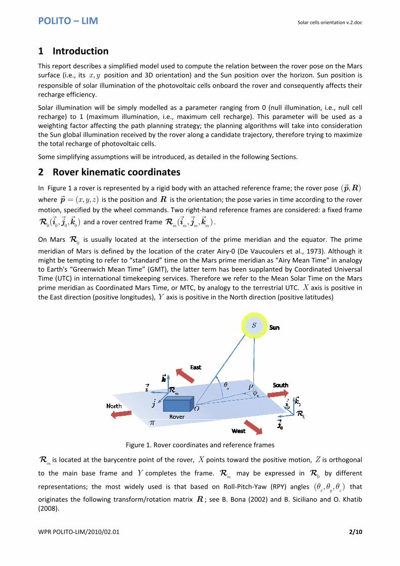
2 Rover kinematic coordinates In Figure 1 a rover is represented by a rigid body with an attached reference frame; the rover pose ( , )p R where ( , , )x y z=p is the position and R is the orientation; the pose varies in time according to the rover motion, specified by the wheel commands. Two right‐hand reference frames are considered: a fixed frame
0 0 0 0( , , )i j kR and a rover centred frame ( , , )
m m m mi j kR .
On Mars 0R is usually located at the intersection of the prime meridian and the equator. The prime
meridian of Mars is defined by the location of the crater Airy‐0 (De Vaucoulers et al., 1973). Although it might be tempting to refer to “standard” time on the Mars prime meridian as “Airy Mean Time” in analogy to Earth's “Greenwich Mean Time” (GMT), the latter term has been supplanted by Coordinated Universal Time (UTC) in international timekeeping services. Therefore we refer to the Mean Solar Time on the Mars prime meridian as Coordinated Mars Time, or MTC, by analogy to the terrestrial UTC. X axis is positive in the East direction (positive longitudes), Y axis is positive in the North direction (positive latitudes)
Figure 1. Rover coordinates and reference frames
mR is located at the barycentre point of the rover, X points toward the positive motion, Z is orthogonal
to the main base frame and Y completes the frame. mR may be expressed in
0R by different
representations; the most widely used is that based on Roll‐Pitch‐Yaw (RPY) angles ( , , )x y zθ θ θ that
originates the following transform/rotation matrix R ; see B. Bona (2002) and B. Siciliano and O. Khatib (2008).

POLITO – LIM Solar cells orientation v.2.doc
WPR POLITO‐LIM/2010/02.01 3/10
11 12 13
21 22 23
31 32 33
r r r
r r r
r r r
⎛ ⎞⎟⎜ ⎟⎜ ⎟⎜ ⎟⎜= ⎟⎜ ⎟⎜ ⎟⎜ ⎟⎟⎜⎝ ⎠
R (1)
with
RPY ‐ A
11
12
13
21
22
23
31
32
33
cos cos
sin sin cos cos sin
cos sin cos sin sin
cos sin
sin sin sin cos cos
cos sin sin sin cos
sin
sin cos
cos cos
y z
x y z x z
x y z x z
y z
x y z x z
x y z x z
y
x y
x y
r
r
r
r
r
r
r
r
r
θ θθ θ θ θ θθ θ θ θ θθ θθ θ θ θ θθ θ θ θ θθ
θ θθ θ
== −= +== += −= −==
(2)
Not all the textbooks and manuals accept this relation; another “definition” of RPY gives origin to an alternative matrix form
RPY ‐ B
11
12
13
21
22
23
31
32
33
cos cos
cos sin
sin
sin sin cos cos sin
sin sin sin cos cos
sin cos
cos sin cos sin sin
cos sin sin sin cos
cos cos
y z
x z
y
x y z x z
x y z x z
x y
x y z x z
x y z x z
x y
r
r
r
r
r
r
r
r
r
θ θθ θ
θθ θ θ θ θθ θ θ θ θθ θθ θ θ θ θ
θ θ θ θ θθ θ
== −== += − += −= − += +=
(3)
We will use always representation RPY‐A in (2), but the reader is advised to check the adopted representation.
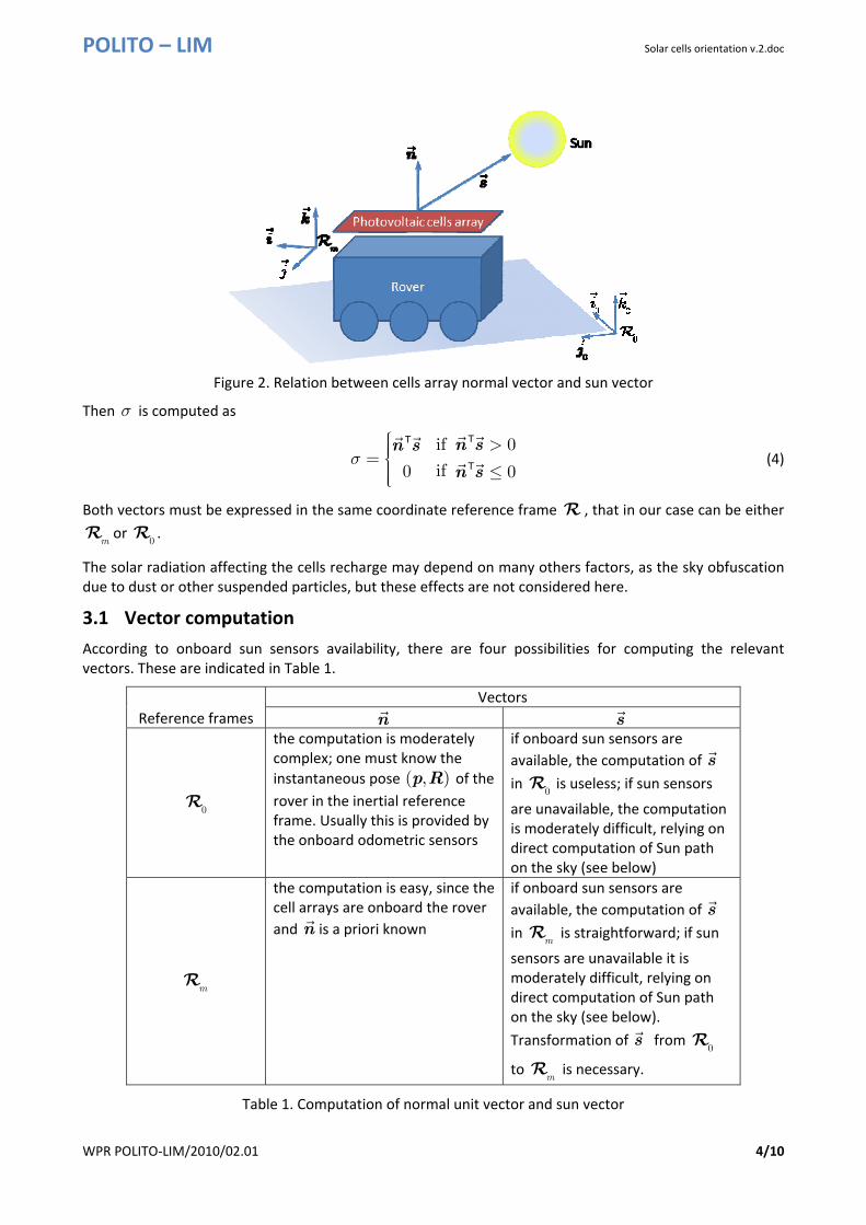
3 Solar illumination model In order to compute the solar illumination parameter 0 1σ≤ ≤ it is necessary to consider two vectors (see Figure 2):
a) the normal unit vector n to the photovoltaic cells array;
b) the unit vector s (also named sun vector) connecting the local rover position to the local Sun position in the sky.
POLITO – LIM Solar cells orientation v.2.doc
WPR POLITO‐LIM/2010/02.01 4/10
Figure 2. Relation between cells array normal vector and sun vector
Then σ is computed as
if 0
if 0 0σ
⎧⎪ >⎪⎪= ⎨⎪ ≤⎪⎪⎩
n sn s
n s
TT
T (4)
Both vectors must be expressed in the same coordinate reference frame R , that in our case can be either
mR or
0R .
The solar radiation affecting the cells recharge may depend on many others factors, as the sky obfuscation due to dust or other suspended particles, but these effects are not considered here.
3.1 Vector computation According to onboard sun sensors availability, there are four possibilities for computing the relevant vectors. These are indicated in Table 1.
Reference frames Vectors
n s
0R
the computation is moderately complex; one must know the instantaneous pose ( , )p R of the rover in the inertial reference frame. Usually this is provided by the onboard odometric sensors
if onboard sun sensors are available, the computation of s in
0R is useless; if sun sensors
are unavailable, the computation is moderately difficult, relying on direct computation of Sun path on the sky (see below)
mR
the computation is easy, since the cell arrays are onboard the rover and n is a priori known
if onboard sun sensors are available, the computation of s in
mR is straightforward; if sun
sensors are unavailable it is moderately difficult, relying on direct computation of Sun path on the sky (see below). Transformation of s from
0R
to mR is necessary.
Table 1. Computation of normal unit vector and sun vector

POLITO – LIM Solar cells orientation v.2.doc
WPR POLITO‐LIM/2010/02.01 5/10
Let us assume that the robot pose is available in 0R as position p and matrix R given by the rover roll‐
pitch‐yaw (RPY) angles, as specified in (2); the matrix R allows to transform vectors in mR to vectors in
0R , as
0
0
m
m
=
=
v Rv
v R vT (5)
3.1.1 Unit vector normal to cells array
As outlined above, two possibilities arise:
a) Normal unit vector is expressed in the rover reference frame mR .
In this case the unit vector is easily computed, since the solar panels are usually positioned on the xy
plane as in Figure 1; therefore =n k , where k is the z axis unit vector of mR . Otherwise ≠n k ,
but all the same it is easily available, and can be considered fixed wrt the rover reference frame (tilting panels are not taken into account).
b) Normal unit vector is in the inertial reference frame 0R . This case will not be considered here.
3.1.2 Sun vector
Having chosen to represent n in mR , we must therefore compute
0s in
0R as and then transform it in
mR as
0
=s R sT
4 Sun path algorithm and sun vector computation The position of the Sun in the sky is given by two angles: the azimuth angle ( )
stφ and the elevation angle
( )stθ , as shown in Figure 1.
Azimuth or solar azimuth angle ( )stφ is the angle between the line OP , i.e., the projection on the ground
plane π of the line OS from the observer to the Sun, and the line from the observer to the geographical South or North, according to the conventions used. A positive azimuth angle generally indicates that the Sun is East of South or North, and a negative azimuth angle generally indicates the Sun is West of South or North.
Solar elevation angle ( )stθ is the angle between the line OS connecting the observer with the Sun and the
horizontal line OP .
A relation that computes both angles is derived taking into account the various astronomical parameters affecting the Sun azimuth and height. These parameters depend on several factors; the principal ones are:
1. The season of the year. Seasons are annual changes in temperature on a planet caused by a combination of two factors: axial tilt (i.e., ecliptic obliquity
0ε ) and variable distance from the Sun.
On Earth, axial tilt determines nearly all of the annual variation, because Earth's orbit is nearly circular. But Mars has a high orbital eccentricity; indeed the distance from the Sun to Mars varies from 1.64 AU to 1.36 AU over a martian year. This large variation, combined with an axial obliquity slightly greater than Earth's (see Table 2), gives rise to seasonal changes far greater than those on Earth.

POLITO – LIM Solar cells orientation v.2.doc
WPR POLITO‐LIM/2010/02.01 6/10
2. The rover position, measured by latitude and longitude: they are related to the position p , but noting that latitude and longitude are given as angles (usually in degrees), while the position p is given as linear quantities in meters. During the rover motion latitudes and longitudes vary very little: Mars has a mean circumference of 21,343 km, therefore a degree of longitude corresponds to a little more than 59 km, and 1 km corresponds to approximately 1.01’ of longitude.
3. The actual time, i.e., the actual local hour measured wrt the day length (sol), that on Mars is slightly larger that on Earth; 1 sol = 24h39.5min.
Obliquity = 0ε
Defined as the planet's axial tilt wrt the ecliptic plane. Earth Mars
23°26'21".4119 = 0.4090926 rad (
0sin ε = 0.397776995)
25°19' = 0.441859 rad (
0sin ε = 0.397776995)
Table 2. Obliquity of Earth and Mars
In order to provide a fast but plausible algorithm for Sun vector computation, the Earth parameters were used instead of the Mars ones.
4.1.1 Local Sun elevation
For any given point on Earth's surface, the Sun elevation angle ( )stθ can be computed as:
sin cos cos cos sin sins L L
Hθ δ Φ δ Φ= +
where
• H is the hour angle; 1 hour = 15o; 0H = at 12:00 local hour, 0H < morning hours, 0H > afternoon hours.
• δ is the Sun declination, computed as ( )36023.45 sin 284
365N
⎛ ⎞⎟⎜ ⎟+⎜ ⎟⎜ ⎟⎟⎜⎝ ⎠.
• N is the day of the year; e.g., March 21st is N =80, June 21st is N =172. •
LΦ is the local latitude.
The sun elevation angle for N =80, L
Φ =45 o is given in Figure 3

POLITO – LIM Solar cells orientation v.2.doc
WPR POLITO‐LIM/2010/02.01 7/10
Figure 3. Sun elevation for N =80,
LΦ =45 o
4.1.2 Local Sun azimuth
The second element of the Sun location is its azimuth ( )stφ . Azimuth angle is positive if toward East, while
is negative if toward West. There are two different ways to compute this angle, as follows
sin sin sin
coscos coss L
ss L
θ Φ δφ
θ Φ−
= (6)
or
cos cos sin sin cos
coscos
L Ls
s
H δ Φ δ Φφ
θ−
= (7)
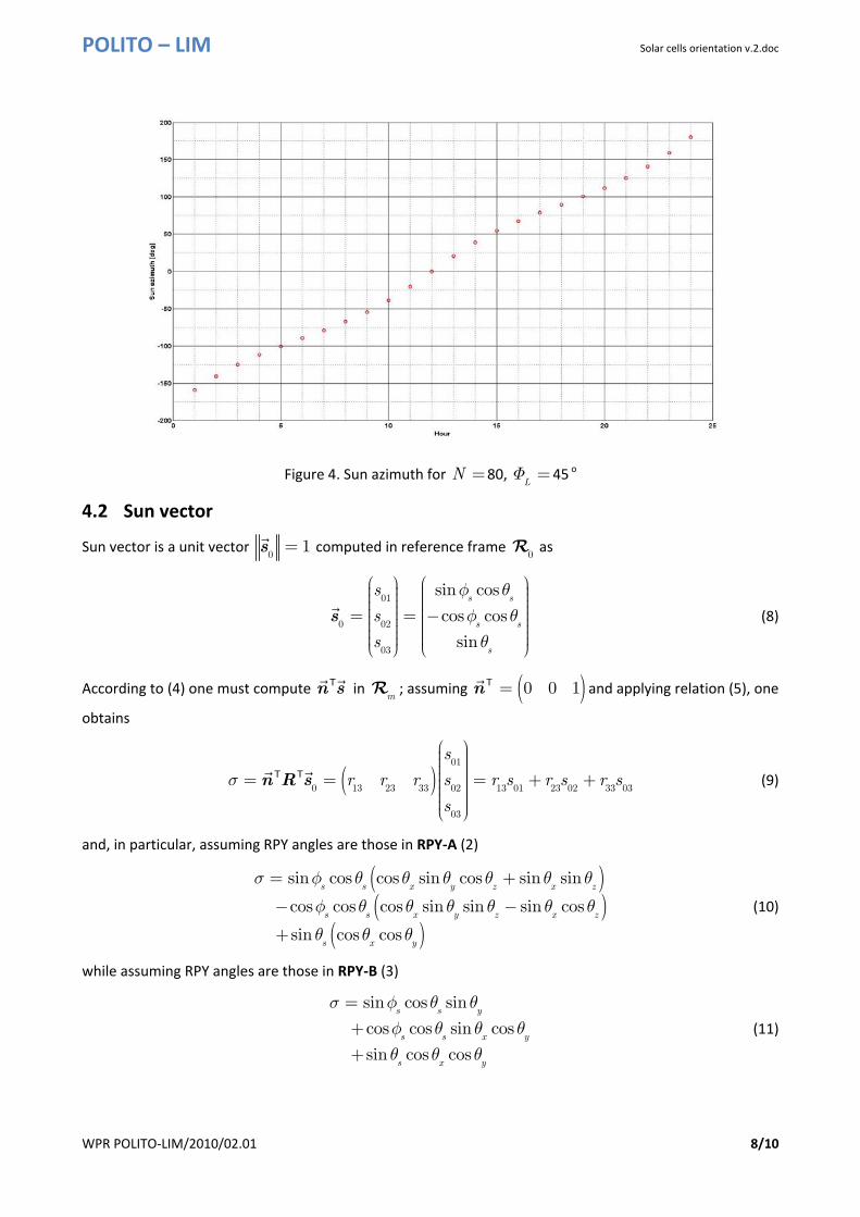
The Sun azimuth for N =80, L
Φ =45 o is given in Figure 4.
POLITO – LIM Solar cells orientation v.2.doc
WPR POLITO‐LIM/2010/02.01 8/10
Figure 4. Sun azimuth for N =80,
LΦ =45 o
4.2 Sun vector
Sun vector is a unit vector 0
1=s computed in reference frame 0R as
01
0 02
03
sin cos
cos cos
sin
s s
s s
s
s
s
s
φ θφ θθ
⎛ ⎞ ⎛ ⎞⎟ ⎟⎜ ⎜⎟ ⎟⎜ ⎜⎟ ⎟⎜ ⎜⎟ ⎟⎜ ⎜= = −⎟ ⎟⎜ ⎜⎟ ⎟⎜ ⎜⎟ ⎟⎜ ⎜⎟ ⎟⎟ ⎟⎜ ⎜⎝ ⎠ ⎝ ⎠
s (8)
According to (4) one must compute n sT in mR ; assuming ( )0 0 1=n T and applying relation (5), one
obtains
( )01
0 13 23 33 02 13 01 23 02 33 03
03
s
r r r s r s r s r s
s
σ
⎛ ⎞⎟⎜ ⎟⎜ ⎟⎜ ⎟⎜= = = + +⎟⎜ ⎟⎜ ⎟⎜ ⎟⎟⎜⎝ ⎠
n R sT T (9)
and, in particular, assuming RPY angles are those in RPY‐A (2)
( )( )
( )
sin cos cos sin cos sin sin
cos cos cos sin sin sin cos
sin cos cos
s s x y z x z
s s x y z x z
s x y
σ φ θ θ θ θ θ θ
φ θ θ θ θ θ θ
θ θ θ
= +
− −
+
(10)
while assuming RPY angles are those in RPY‐B (3)
sin cos sin
cos cos sin cos
sin cos cos
s s y
s s x y
s x y
σ φ θ θφ θ θ θθ θ θ
=++
(11)
POLITO – LIM Solar cells orientation v.2.doc
WPR POLITO‐LIM/2010/02.01 9/10
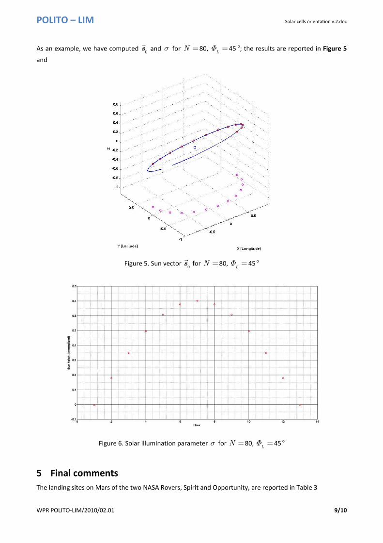
As an example, we have computed 0s and σ for N =80,
LΦ =45 o; the results are reported in Figure 5
and
Figure 5. Sun vector 0s for N =80,
LΦ = 45 o
Figure 6. Solar illumination parameter σ for N =80,
LΦ =45 o
5 Final comments The landing sites on Mars of the two NASA Rovers, Spirit and Opportunity, are reported in Table 3

POLITO – LIM Solar cells orientation v.2.doc
WPR POLITO‐LIM/2010/02.01 10/10
Rover Name Latitude Longitude Spirit 14.57°S 175.48°E
Opportunity 1.95°S 354.47°E
Table 3. NASA MER’s landing sites
A realistic simulation of the computation of the various quantities described in this Report can be carried out considering a rover position not too far from the equator ( approximately 0° Latitude) and around 0° Longitude. The simulation can start at mid‐morning and end a couple of hours later (10:00‐12:00 or 12:00‐14:00).
Figure 7. Spirit (left) and Opportunity (right) landing sites
6 References Bona B. (2002) Modellistica dei Robot Industriali (2002), CELID, Torino.
Siciliano B., Khatib O. (Eds.) (2008), Springer Handbook of Robotics, Springer.
De Vaucouleurs G., Davies M.E., Sturms F.M. (1973), “Mariner 9 areographic coordinate system.” J. Geophys. Res. 78, 4395‐4404.
7 Acronyms and Abbreviations AU = Astronomical Units
MER = Mars Exploration Rover
MTC = Coordinated Mars Time
RPY = Roll‐Pitch‐Yaw
UTC = Coordinated Universal Time
wrt = with respect to