solar datatechnology 485pb-smc-nrfiles.sma.de/dl/22127/485pb_smc_nr_ien082310.pdf · sma solar...
TRANSCRIPT

Solar Datatechnology485PB-SMC-NR Installation Guide
485PB-SMC-NR-IEN082310 | 98-00010710 | Version 1.0 EN

SMA Solar Technology AG Table of Contents
Installation Guide 485PB-SMC-NR-IEN082310 3
Table of Contents
1 Notes on this Manual. . . . . . . . . . . . . . . . . . . . . . . . . . . . . . 5
1.1 Area of Validity . . . . . . . . . . . . . . . . . . . . . . . . . . . . . . . . . . . . . 5
1.2 Target group. . . . . . . . . . . . . . . . . . . . . . . . . . . . . . . . . . . . . . . . 5
1.3 Symbols used . . . . . . . . . . . . . . . . . . . . . . . . . . . . . . . . . . . . . . . 5
2 Safety . . . . . . . . . . . . . . . . . . . . . . . . . . . . . . . . . . . . . . . . . . 6
2.1 Appropriate usage . . . . . . . . . . . . . . . . . . . . . . . . . . . . . . . . . . . 6
2.2 Safety Precautions . . . . . . . . . . . . . . . . . . . . . . . . . . . . . . . . . . . 6
3 Unpacking. . . . . . . . . . . . . . . . . . . . . . . . . . . . . . . . . . . . . . . 7
3.1 Packing list . . . . . . . . . . . . . . . . . . . . . . . . . . . . . . . . . . . . . . . . . 7
3.2 Identification . . . . . . . . . . . . . . . . . . . . . . . . . . . . . . . . . . . . . . . . 7
4 Electrical connection. . . . . . . . . . . . . . . . . . . . . . . . . . . . . . . 8
4.1 Overview of interface port and cable route . . . . . . . . . . . . . . . 8
4.2 Installing the communication interface . . . . . . . . . . . . . . . . . . . . 9
4.3 Connecting the communication interface. . . . . . . . . . . . . . . . . . 9
4.4 Termination . . . . . . . . . . . . . . . . . . . . . . . . . . . . . . . . . . . . . . . . 12
5 Decommissioning . . . . . . . . . . . . . . . . . . . . . . . . . . . . . . . . 13
6 Contact . . . . . . . . . . . . . . . . . . . . . . . . . . . . . . . . . . . . . . . . 14
Table of Contents SMA Solar Technology AG
4 485PB-SMC-NR-IEN082310 Installation Guide
SMA Solar Technology AG Notes on this Manual
Installation Guide 485PB-SMC-NR-IEN082310 5
1 Notes on this Manual
1.1 Area of ValidityThis manual applies for the add-on kit of the RS485 Piggy-Back (485PB-SMC-NR) for inverters of type:
• SMC 6000TL, SMC 7000TL, SMC 8000TL, SMC 9000TL-10, SMC 10000TL-10, SMC 11000TL-10
• SMC/WB 5000(A), SMC/WB 6000(A)
• SMC7000HV
1.2 Target groupThis manual is intended for the installer.
1.3 Symbols usedThe following types of warnings and general information appear in this document:
DANGER!
DANGER indicates a hazardous situation which, if not avoided, will result in death or serious injury.
NOTICE!
NOTICE indicates a situation that could result in damage to property if not avoided!
Information
Information provides tips that are valuable for the optimal operation of the product.
Safety SMA Solar Technology AG
6 485PB-SMC-NR-IEN082310 Installation Guide
2 Safety
2.1 Appropriate usageThe 485PB-SMC-NR is an add-on kit for inverters of type:
• SMC 6000TL, SMC 7000TL, SMC 8000TL, SMC 9000TL-10, SMC 10000TL-10, SMC 11000TL-10
• SMC/WB 5000(A), SMC/WB 6000(A),
• SMC7000HV
The communication interface enables a cable-connected RS485 communication of the inverter to be established.
The Piggy-Back is only suitable for use with the above-named SMA inverter types. Also observe the relevant inverter manual.
2.2 Safety Precautions
DANGER!Risk of lethal electric shock when opening the inverter.
• All work on the inverter must be carried out by a qualified electrician.
• Disconnect the inverter on the AC and DC sides as described in the inverter manual.
NOTICE!Electrostatic discharges can damage the RS485 Piggy-Back.
• Avoid touching the component connections and plug contacts.
• Ground yourself before removing the Piggy-Back from the inverter by touching the PE or a non-coated part of the inverter housing.
SMA Solar Technology AG Unpacking
Installation Guide 485PB-SMC-NR-IEN082310 7
3 Unpacking
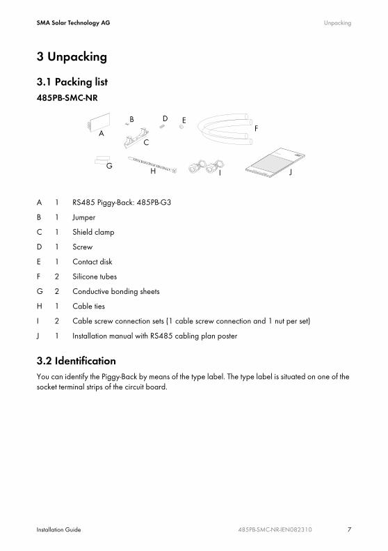
3.1 Packing list485PB-SMC-NR
3.2 IdentificationYou can identify the Piggy-Back by means of the type label. The type label is situated on one of the socket terminal strips of the circuit board.
A 1 RS485 Piggy-Back: 485PB-G3
B 1 Jumper
C 1 Shield clamp
D 1 Screw
E 1 Contact disk
F 2 Silicone tubes
G 2 Conductive bonding sheets
H 1 Cable ties
I 2 Cable screw connection sets (1 cable screw connection and 1 nut per set)
J 1 Installation manual with RS485 cabling plan poster
A
B
C
D EF
GH I J
Electrical connection SMA Solar Technology AG
8 485PB-SMC-NR-IEN082310 Installation Guide
4 Electrical connectionThis section describes the installation and connection of the RS485 Piggy-Back communication interface.
It is assumed that the inverter is situated in the middle of the RS485 communication bus. If the inverter is situated at the end of the RS485 communication bus, carry out the following steps for one cable only and set the termination (see Section 4.4).
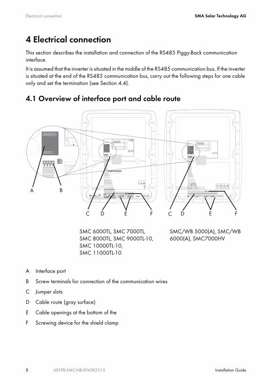
4.1 Overview of interface port and cable route
SMC 6000TL, SMC 7000TL, SMC 8000TL, SMC 9000TL-10, SMC 10000TL-10, SMC 11000TL-10
SMC/WB 5000(A), SMC/WB 6000(A), SMC7000HV
A Interface port
B Screw terminals for connection of the communication wires
C Jumper slots
D Cable route (gray surface)
E Cable openings at the bottom of the
F Screwing device for the shield clamp
C
BA
D E F E FDC
SMA Solar Technology AG Electrical connection
Installation Guide 485PB-SMC-NR-IEN082310 9
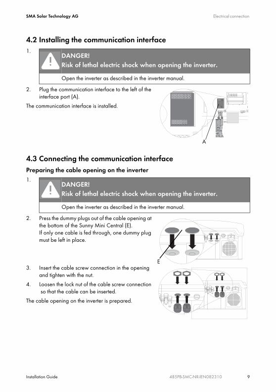
4.2 Installing the communication interface1.
2. Plug the communication interface to the left of the interface port (A).
The communication interface is installed.
4.3 Connecting the communication interfacePreparing the cable opening on the inverter1.
2. Press the dummy plugs out of the cable opening at the bottom of the Sunny Mini Central (E).If only one cable is fed through, one dummy plug must be left in place.
3. Insert the cable screw connection in the opening and tighten with the nut.
4. Loosen the lock nut of the cable screw connection so that the cable can be inserted.
The cable opening on the inverter is prepared.
DANGER!Risk of lethal electric shock when opening the inverter.
Open the inverter as described in the inverter manual.
DANGER!Risk of lethal electric shock when opening the inverter.
Open the inverter as described in the inverter manual.
A
E
Electrical connection SMA Solar Technology AG
10 485PB-SMC-NR-IEN082310 Installation Guide
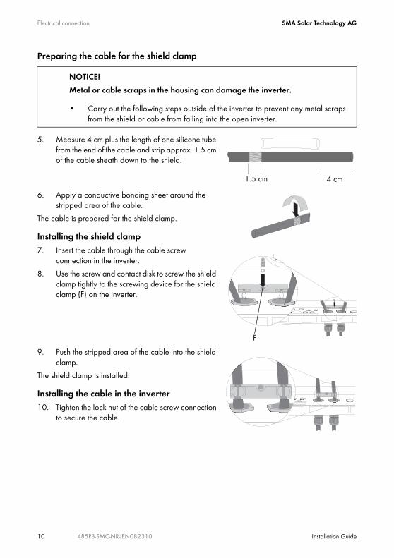
Preparing the cable for the shield clamp
5. Measure 4 cm plus the length of one silicone tube from the end of the cable and strip approx. 1.5 cm of the cable sheath down to the shield.
6. Apply a conductive bonding sheet around the stripped area of the cable.
The cable is prepared for the shield clamp.
Installing the shield clamp7. Insert the cable through the cable screw
connection in the inverter.
8. Use the screw and contact disk to screw the shield clamp tightly to the screwing device for the shield clamp (F) on the inverter.
9. Push the stripped area of the cable into the shield clamp.
The shield clamp is installed.
Installing the cable in the inverter10. Tighten the lock nut of the cable screw connection
to secure the cable.
NOTICE!
Metal or cable scraps in the housing can damage the inverter.
• Carry out the following steps outside of the inverter to prevent any metal scraps from the shield or cable from falling into the open inverter.
1.5 cm 4 cm
F
SMA Solar Technology AG Electrical connection
Installation Guide 485PB-SMC-NR-IEN082310 11
11.
12. Lay the cable to the interface port, with the silicone tube within the cable route (D).
The cable is installed in the inverter.
Connecting the cable to the communication interface
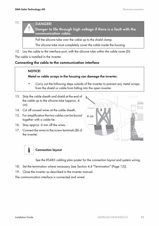
13. Strip the cable sheath and shield at the end of the cable up to the silicone tube (approx. 4 cm).
14. Cut off unused wires at the cable sheath.
15. For simplification the two cables can be bound together with a cable tie.
16. Strip approx. 6 mm off the wires.
17. Connect the wires to the screw terminals (B) of the inverter.
18. Set the termination where necessary (see Section 4.4 "Termination" (Page 12)).
19. Close the inverter as described in the inverter manual.
The communication interface is connected and wired.
DANGER!Danger to life through high voltage if there is a fault with the communication cable.
Pull the silicone tube over the cable up to the shield clamp.
The silicone tube must completely cover the cable inside the housing.
NOTICE!
Metal or cable scraps in the housing can damage the inverter.
• Carry out the following steps outside of the inverter to prevent any metal scraps from the shield or cable from falling into the open inverter.
Connection layout
See the RS485 cabling plan poster for the connection layout and system wiring.
B
4 cm
Electrical connection SMA Solar Technology AG
12 485PB-SMC-NR-IEN082310 Installation Guide
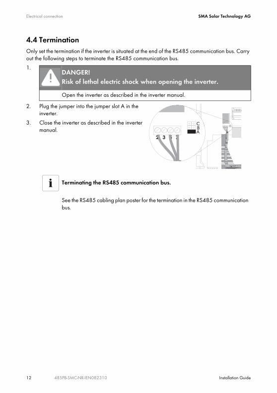
4.4 TerminationOnly set the termination if the inverter is situated at the end of the RS485 communication bus. Carry out the following steps to terminate the RS485 communication bus.
1.
2. Plug the jumper into the jumper slot A in the inverter.
3. Close the inverter as described in the inverter manual.
DANGER!Risk of lethal electric shock when opening the inverter.
Open the inverter as described in the inverter manual.
Terminating the RS485 communication bus.
See the RS485 cabling plan poster for the termination in the RS485 communication bus.
SMA Solar Technology AG Decommissioning
Installation Guide 485PB-SMC-NR-IEN082310 13
5 Decommissioning1.
2. Disconnect the wires from the screw terminals (B)
3. Remove the jumper, if applicable.
4. Remove the cable tie, if applicable.
5. Remove the silicone tube.
6. Unscrew the lock nut from the cable screw connection.
7. Pull the cable out of the shield clamp.
8. Pull the cable out from the bottom of the device.
9. Unscrew the shield clamp.
10. Remove the cable screw connection from the device.
11. Close the cable opening at the bottom of the Sunny Mini Central (E) with the dummy plugs.
12. Remove the communication interface.
13. Close the inverter as described in the inverter manual.
The communication interface has been decommissioned.
DANGER!Risk of lethal electric shock when opening the inverter.
Open the inverter as described in the inverter manual.
Contact SMA Solar Technology AG
14 485PB-SMC-NR-IEN082310 Installation Guide
6 ContactIf you have technical problems concerning our products, contact the SMA Service Line. We require the following information in order to provide you with the necessary assistance:
• Inverter type
• Serial number of the Sunny Mini Central / Windy Boy
• Type and number of modules connected
• Communication method
• Blink code or display of the Sunny Mini Central / Windy Boy
SMA Solar Technology AG
Sonnenallee 1
34266 Niestetal, Germany
Tel. +49 561 9522 499
Fax +49 561 9522 4699
www.SMA.de
SMA Solar Technology AG Legal Restrictions
Installation Guide 485PB-SMC-NR-IEN082310 15
The information contained in this document is the property of SMA Solar Technology AG. Publishing its content, either partially or in full, requires the written permission of SMA Solar Technology AG. Any internal company copying of the document for the purposes of evaluating the product or its correct implementation is allowed and does not require permission.
Exclusion of liabilityThe general terms and conditions of delivery of SMA Solar Technology AG shall apply.
The content of these documents is continually checked and amended, where necessary. However, discrepancies cannot be excluded. No guarantee is made for the completeness of these documents. The latest version is available online at www.SMA.de or from the usual sales channels.
Guarantee or liability claims for damages of any kind are excluded if they are caused by one or more of the following:
• Damages during transportation
• Improper or inappropriate use of the product
• Operating the product in an unintended environment
• Operating the product whilst ignoring relevant, statutory safety regulations in the deployment location
• Ignoring safety warnings and instructions contained in all documents relevant to the product
• Operating the product under incorrect safety or protection conditions
• Altering the product or supplied software without authority
• The product malfunctions due to operating attached or neighboring devices beyond statutory limit values
• In case of unforeseen calamity or force majeure
The use of supplied software produced by SMA Solar Technology AG is subject to the following conditions:
• SMA Solar Technology AG rejects any liability for direct or indirect damages arising from the use of software developed by SMA Solar Technology AG. This also applies to the provision or non-provision of support activities.
• Supplied software not developed by SMA Solar Technology AG is subject to the respective licensing and liability agreements of the manufacturer.
SMA Factory WarrantyThe current guarantee conditions come enclosed with your device. These are also available online at www.SMA.de and can be downloaded or are available on paper from the usual sales channels if required.
TrademarksAll trademarks are recognized even if these are not marked separately. Missing designations do not mean that a product or brand is not a registered trademark.
SMA Solar Technology AG
Sonnenallee 1
34266 Niestetal
Germany
Tel. +49 561 9522-0
Fax +49 561 9522-100
www.SMA.de
E-Mail: [email protected]
© 2004 to 2008 SMA Solar Technology AG. All rights reserved

SMA Solar Technology AG
Sonnenallee 1
34266 Niestetal, Germany
Tel.: +49 561 9522 4000
Fax: +49 561 9522 4040
E-Mail: [email protected]
Freecall: 0800 SUNNYBOY
Freecall: 0800 78669269
www.SMA.de