solar dynamic heat pipe development and .../67531/metadc710462/...solar dynamic heat pipe...
TRANSCRIPT

- -
SOLAR DYNAMIC HEAT PIPE DEVELOPMENT AND ENDURANCE TEST
CONTRACT NO. 9 - X6H - 8102L - 1 MONTHLY TECHNICAL PROGRESS REPORT NO. 6
29 OCTOBER TO NOVEMBER 30, 1987
PREPARED FOR LOS ALAMOS NATIONAL LABORATORY LOS ALAMOS, NEW MEXICO 87545
APPROVED BY: I -_ 1 \ TG . (&2IDENREICH 1 PROGRAM W A G E E
(G.HIL~~SPACE-STATTON-SECTION - MANAGER -
CRTXUDEY 1 ENGINEERIN-FM~AGER--- h

DISCLAIMER
This report was prepared as an account of work sponsored by an agency of the United States Government Neither the Unitai States Government nor any agency thereof, nor any of their employees, makes any warranty, express or implied, or assumes any legal liability or responsibility for the accuracy, completeness, or use- fulness of any information, apparatus, product, or process disclosed, or represents that its use would not infringe privately owned rights. Reference herein to any spe- cific commercial product, process, or seMw by trade name, trademark, manufac- turer, or otherwise does not necessarily constitute or imply its endorsement, recom- mendation, or favoring by the United States Government or any agency thereof. The views and opinions of authors expressed herein do not necessarily state or reflect those of the United States Government or any agency thereof.

DISCLAIMER
Portions of this document may be illegible electronic image products. Images are produced from the best available original document.

I. Introduction
The Space Station requires a high level of reliable electric power. in which power is provided by photovoltaic arrays and by solar dynamic power conversion modules. The organic Rankine cycle (ORC) engine is one approach to solar dynamic conversion. The ORC provides the attributes of high efficiency at low temperature and compact simple designs utilizing conventional techniques and materials. The heat receiver is one area which must be addressed in applying the proven ORC to long life applications such as the Space Station. Heat pipes with integral thermal energy storage (TES) canisters and a toluene heater tube are the prime components of the heat receiver from the Phase B preliminary design. This contract is a task order type addressing the design, fabrication and testing of a full scale heat pipe. The contract was initiated on April 16, 1987. Sundstrand has specific responsibilities in each task. Los Alamos National Laboratory (LANL) in turn has the prime contract responsibility to NASA-LeRC.
The baseline approach is to utilize a hybrid system
Task 1 - Transient Tests with the Phase B Heat Pipe The objective of these tests is the determination of the operating characteristics and power input limits of the heat pipe under conditions corresponding to reacquisition of the sun during emergence from eclipse or conditions corresponding to initial startup of the solar dynamic power system. contract NAS3-24666 will be used for these tests. The tests will be conducted by LANL in a vacuum test facility. After completion of these tests, the heat pipe is to be disassembled, inspected and analyzed. Sundstrand's responsibilities for Task 1 are:
The heat pipe designed and fabricated under NASA
1. 2. 3. 4.
Review LANL test plans. Witness (at our option) and analyze all tests. Witness disassembly of the heat pipe. Upon receipt of the canisters'from the disassembled heat pipe, perform chemical and metallurgical analysis on the canisters and LiOH salt.
Task 2 - New Heat Pipe Design Fabrication and Testing The objective of this task is to design, fabricate and performance test a new heat pipe with thermal energy storage and a simulated toluene heater. Structural analysis and a random vibration test of the complete assembly are to be performed. conducted before and after the dynamic testing. ,S.undstsand's a .
Performance characterization by test is to be . . I . z .. responsibilities for Task 2 are:
, I
1.
2. 3 .
4 .
5.
6.
. ' 1 L - .
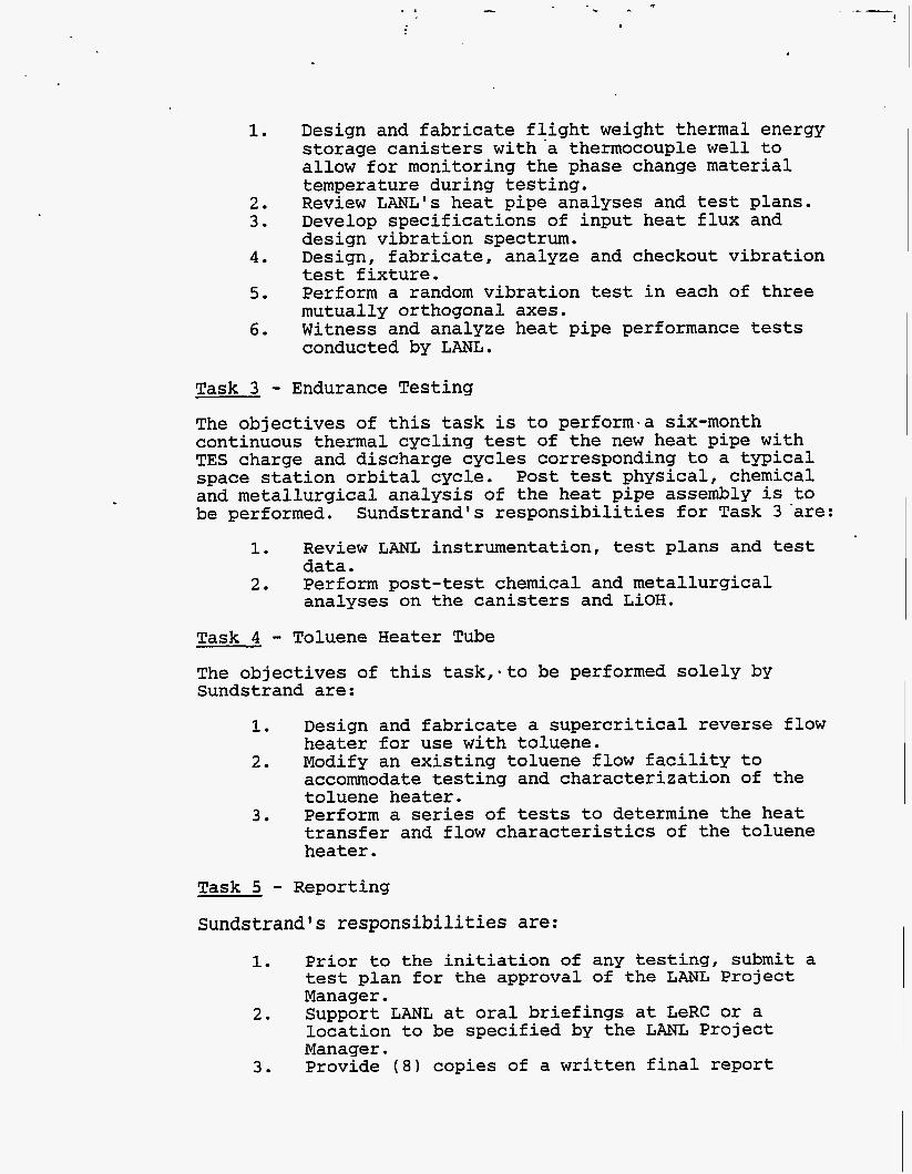
Design and fabricate flight weight thermal energy storage canisters with-a thermocouple well to allow for monitoring the phase change material temperature during testing. Review LANL's heat pipe analyses and test plans. Develop specifications of input heat flux and design vibration spectrum. Design, fabricate, analyze and checkout vibration test fixture. Perform a random vibration test in each of three mutually orthogonal axes. Witness and analyze heat pipe performance tests conducted by LANL.
Task 3 - Endurance Testing The objectives of this task is to perform-a six-month continuous thermal cycling test of the new heat pipe with TES charge and discharge cycles corresponding to a typical space station orbital cycle. Post test physical, chemical and metallurgical analysis of the heat pipe assembly is to be performed. Sundstrand's responsibilities for Task 3 'are:
1.
2.
Review LANL instrumentation, test plans and test data. Perform post-test chemical and metallurgical analyses on the canisters and LiOH.
Task 4 - Toluene Heater Tube The objectives of this task,sto be performed solely by Sundstrand are:
1.
2.
3 .
Design and fabricate a supercritical reverse flow heater for use with toluene. Modify an existing toluene flow facility to accommodate testing and characterization of the toluene heater. Perform a series of tests to determine the heat transfer and flow characteristics of the toluene heater.
Task 5 - Reporting Sundstrand's responsibilities are:
1.
2.
3 .
Prior to the initiation of any testing, submit a test plan for the approval of the LANL Project Manager. Support LANL at oral briefings at LeRC or a location to be specified by the LANL Project Manager. Provide (8) copies of a written final report

giving each task objective, approach, design, fabrication and testing details to LANL at the completion of the total program.
11. Technical Prowess Summary
Overview
This report covers the period from October 29 to November 30, 1987. The primary activities were the installation of the toluene heater tube in the test facility and the design modifications of the vibration fixture. Figure 1 shows the Sundstrand program schedule and milestones.
Task 1 - Transient Tests on the Existing Phase B Heat Pipe Testing was completed and reported in Reference 1. of the TES canisters is on hold pending Phase B heat disassembly.
Analysis
Task 2 - New Heat Pipe Design, Fabrication and Testing The design of heat pipe vibration fixture was completed and reported in Reference 2. vibration fixture and recommended several changes. changes were to incorporate a top plate on the welded side of the vibration fixture and to install pins to hold stainless sleeves. The purpose of these modifications was. to increase the resonant frequency in the axial axis and to provide the positive retaining mechanism for the sleeves. These changes were incorporated in the heat pipe vibration fixture drawing. receiving the LANL approval.
The instrumentation details for the heat pipe vibration test was discussed with LANL. A total of thirteen (13) accelerometers were planned to be used for monitoring the dynamic response of the heat pipe. Two of these accelerometers are to be installed in the heater section of the heat pipe by LANL. Two input accelerometers will also be installed on the fixture.
LANL reviewed the heat pipe The
The fixture will be modified after
Task 4 - Toluene Heater Tube (THT) Disc Fin Heater Tube The disc fin toluene heater tube was instrumented with twenty ( 2 0 ) thermocouples located along the axial length. After installation of the instrumentation, the toluene heater tube was assembled with the isolation box and plumbed with the inlet/outlet toluene ports. The entige assembly was helium leak checked and passed the 1 x 10 requirement. The heater tube assembly with the isolation box was installed in the fluidized bed. isolation box was to thermally insulate the toluene
scc/sec'
The purpose of the

inlet/outlet ports of the heater tube. plumbing was completed between the toluene heater tube and the test facility. helium leak checking the toluene test loop.
All necessary
The fitting connections were verified by
Prior to installation of the heater tube in the fluidized bed, the operation of the fluidized bed was checked out. During this checkout run, the retort walls deformed due to the thermal stresses developeQ in the rgtort. phenomena was observed at 300 F and 900 F runs. this distortion has no direct effect on the toluene heater tube testing.
This However,
The thermal performance testing of the disc fin heater tube will be started in January 1988.
Longitudinal Heater Tube
About thirty (30) vendors were contacted to review and provide budgetary quotes for the welded thermal standoff assembly of the longitudinal fin heater as shown in Figure 6. and the lead time was about 8 to 12 weeks. put on hold.
The budgetary quote ranged from $2.1K to $S.OK per unit This activity is
Work Planned for the Next Reportinq Period
Task 2
o Modify vibration fixture o o o
Perform checkout test on the vibration fixture Receive heat pipe from LANL for dynamic testing Incorporate the LANL comments in the test plan
Task 4
o o o
Incorporate the LANL comments in the test plan Charge toluene heater tube test facility with toluene Begin thermal performance test on the disc fin toluene heater tube
References
1. 9-X6H-8102L-l Solar Dynamic heat Pipe Development and Endurance Test Monthly Technical Progress Report No. 1, dated June 26, 1987.
2. 9-X6H-8102L-1 Solar Dynamic Heat Pipe Development and Endurance Test Monthly Technical Progress Report No. 4, dated September 29, 1987.

i I
I I ! 1 1 i
1
I