solar pump inverter user’s manual
TRANSCRIPT
www.sigineer.com
Solar Pump Inverter User’s Manual
For Asynchronous Motor
2200W to 22000W
Version 2.0 (PN:60000-2021188)
Last Edition: Sep 6th 2021
Manufacturer Information
Sigineer Power Limited
Email: [email protected]
TEL: +86 769 82817616
US Warehouse: 4415 S 32nd St, Phoenix AZ 85040
www.sigineer.com
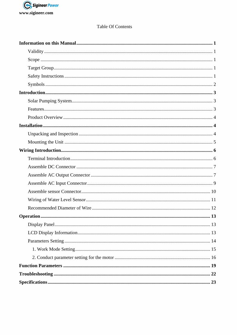
Table Of Contents
Information on this Manual .................................................................................................................. 1
Validity ............................................................................................................................................. 1
Scope ................................................................................................................................................ 1
Target Group ..................................................................................................................................... 1
Safety Instructions ............................................................................................................................ 1
Symbols ............................................................................................................................................ 2
Introduction ............................................................................................................................................ 3
Solar Pumping System...................................................................................................................... 3
Features ............................................................................................................................................. 3
Product Overview ............................................................................................................................. 4
Installation .............................................................................................................................................. 4
Unpacking and Inspection ................................................................................................................ 4
Mounting the Unit ............................................................................................................................ 5
Wiring Introduction............................................................................................................................... 6
Terminal Introduction ....................................................................................................................... 6
Assemble DC Connector .................................................................................................................. 7
Assemble AC Output Connector ...................................................................................................... 7
Assemble AC Input Connector ......................................................................................................... 9
Assemble sensor Connector ............................................................................................................ 10
Wiring of Water Level Sensor ........................................................................................................ 11
Recommended Diameter of Wire ................................................................................................... 12
Operation .............................................................................................................................................. 13
Display Panel .................................................................................................................................. 13
LCD Display Information ............................................................................................................... 13
Parameters Setting .......................................................................................................................... 14
1. Work Mode Setting ................................................................................................................. 15
2. Conduct parameter setting for the motor ................................................................................ 16
Function Parameters ........................................................................................................................... 19
Troubleshooting ................................................................................................................................... 22
Specifications ........................................................................................................................................ 23
www.sigineer.com
1
Information on this Manual
Validity
This manual is valid for the following solar pump inverters:
P2.2ST (Single phase/Three Phase 220Vac, with AC input)
P4KST (Single phase/Three Phase 220Vac, with AC input)
P4KT3 (Three Phase 380Vac, with AC input)
P7.5KT3 (Three Phase 380Vac, without AC input)
P11KT3 (Three Phase 380Vac, without AC input)
P15KT3 (Three Phase 380Vac, without AC input)
P18.5KT3 (Three Phase 380Vac, without AC input)
P22KT3 (Three Phase 380Vac, without AC input)
Scope
This manual describes the assembly, installation, operation and troubleshooting of this
unit. Please read this manual carefully before installations and operations.
Target Group
This document is intended for qualified persons and end users. Tasks that do not require
any particular qualification can also be performed by end users. Qualified persons must
have the following skills:
Knowledge of how a pump inverter works and is operated
Training in how to deal with the dangers and risks associated with installing and
using electrical devices and installations
Training in the installation and commissioning of electrical devices and
installations.
Knowledge of the applicable standards and directives
Knowledge of and compliance with this document and all safety information
Safety Instructions
WARNING: This chapter contains important safety and operating instructions.
Read and keep this manual for future reference.
Inspection
If missing components or damaged inverter is found after receiving, please do NOT install or
operate it. Otherwise, it may cause human injury or equipment damage.
Installation
www.sigineer.com
2
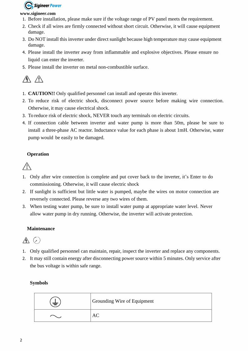
1. Before installation, please make sure if the voltage range of PV panel meets the requirement.
2. Check if all wires are firmly connected without short circuit. Otherwise, it will cause equipment
damage.
3. Do NOT install this inverter under direct sunlight because high temperature may cause equipment
damage.
4. Please install the inverter away from inflammable and explosive objectives. Please ensure no
liquid can enter the inverter.
5. Please install the inverter on metal non-combustible surface.
1. CAUTION!! Only qualified personnel can install and operate this inverter.
2. To reduce risk of electric shock, disconnect power source before making wire connection.
Otherwise, it may cause electrical shock.
3. To reduce risk of electric shock, NEVER touch any terminals on electric circuits.
4. If connection cable between inverter and water pump is more than 50m, please be sure to
install a three-phase AC reactor. Inductance value for each phase is about 1mH. Otherwise, water
pump would be easily to be damaged.
Operation
1. Only after wire connection is complete and put cover back to the inverter, it’s Enter to do
commissioning. Otherwise, it will cause electric shock
2. If sunlight is sufficient but little water is pumped, maybe the wires on motor connection are
reversely connected. Please reverse any two wires of them.
3. When testing water pump, be sure to install water pump at appropriate water level. Never
allow water pump in dry running. Otherwise, the inverter will activate protection.
Maintenance
1. Only qualified personnel can maintain, repair, inspect the inverter and replace any components.
2. It may still contain energy after disconnecting power source within 5 minutes. Only service after
the bus voltage is within safe range.
Symbols
Grounding Wire of Equipment
AC

www.sigineer.com
3
DC
Phase
Before operating inverter, please read the instruction.
5
minutes
In order to avoid electric shock, cut off the inverter from
PV terminal and AC terminal for at least 5 minutes, then
contact the wire of machine output terminal and input
terminal.
Warning: when machine works, the temperature of metal
shell may be very high.
www.sigineer.com
4
Pump
Introduction
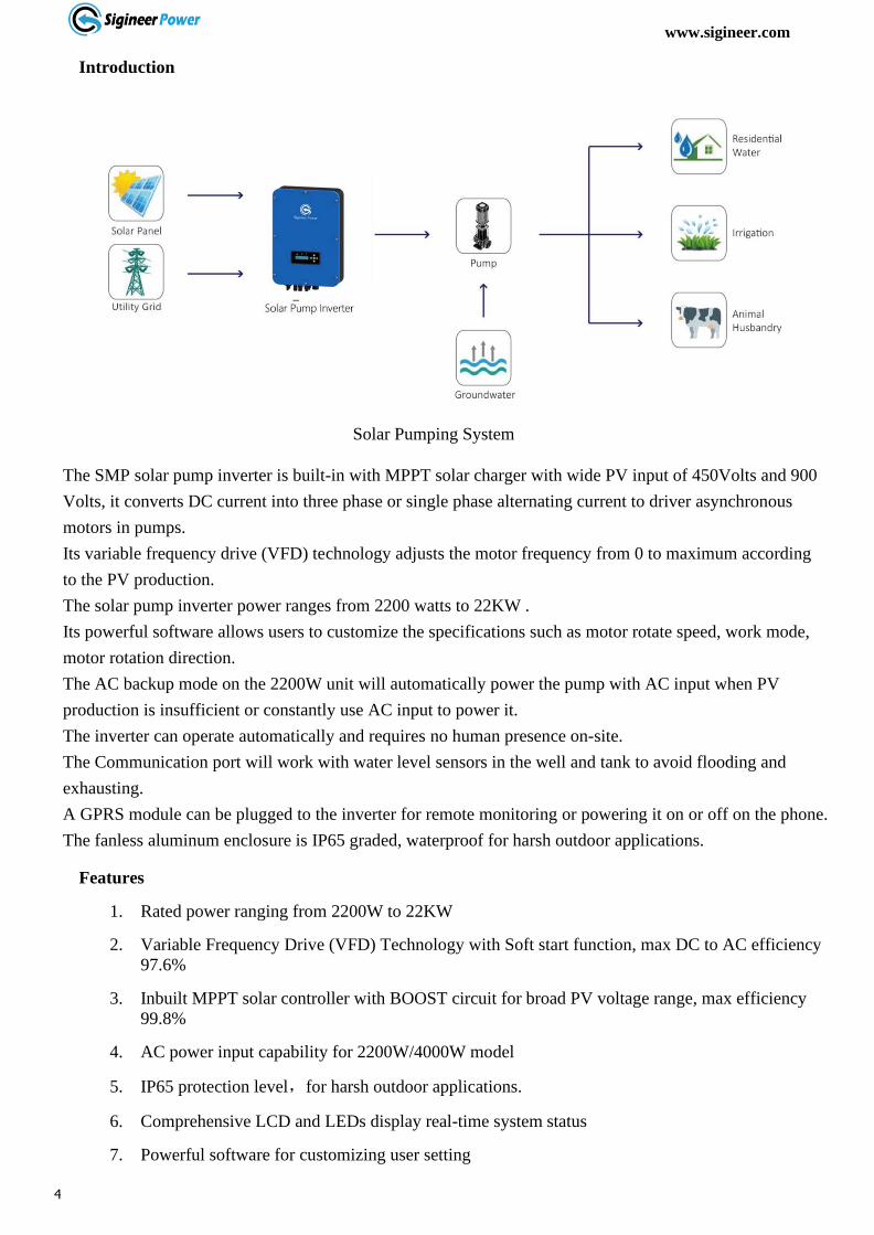
Solar Pumping System
The SMP solar pump inverter is built-in with MPPT solar charger with wide PV input of 450Volts and 900
Volts, it converts DC current into three phase or single phase alternating current to driver asynchronous
motors in pumps.
Its variable frequency drive (VFD) technology adjusts the motor frequency from 0 to maximum according
to the PV production.
The solar pump inverter power ranges from 2200 watts to 22KW .
Its powerful software allows users to customize the specifications such as motor rotate speed, work mode,
motor rotation direction.
The AC backup mode on the 2200W unit will automatically power the pump with AC input when PV
production is insufficient or constantly use AC input to power it.
The inverter can operate automatically and requires no human presence on-site.
The Communication port will work with water level sensors in the well and tank to avoid flooding and
exhausting.
A GPRS module can be plugged to the inverter for remote monitoring or powering it on or off on the phone.
The fanless aluminum enclosure is IP65 graded, waterproof for harsh outdoor applications.
Features
1. Rated power ranging from 2200W to 22KW
2. Variable Frequency Drive (VFD) Technology with Soft start function, max DC to AC efficiency
97.6%
3. Inbuilt MPPT solar controller with BOOST circuit for broad PV voltage range, max efficiency
99.8%
4. AC power input capability for 2200W/4000W model
5. IP65 protection level,for harsh outdoor applications.
6. Comprehensive LCD and LEDs display real-time system status
7. Powerful software for customizing user setting

www.sigineer.com
5
8. Lightning Protection
9. Remote monitoring through GPRS module (Sold Separately)
www.sigineer.com
6
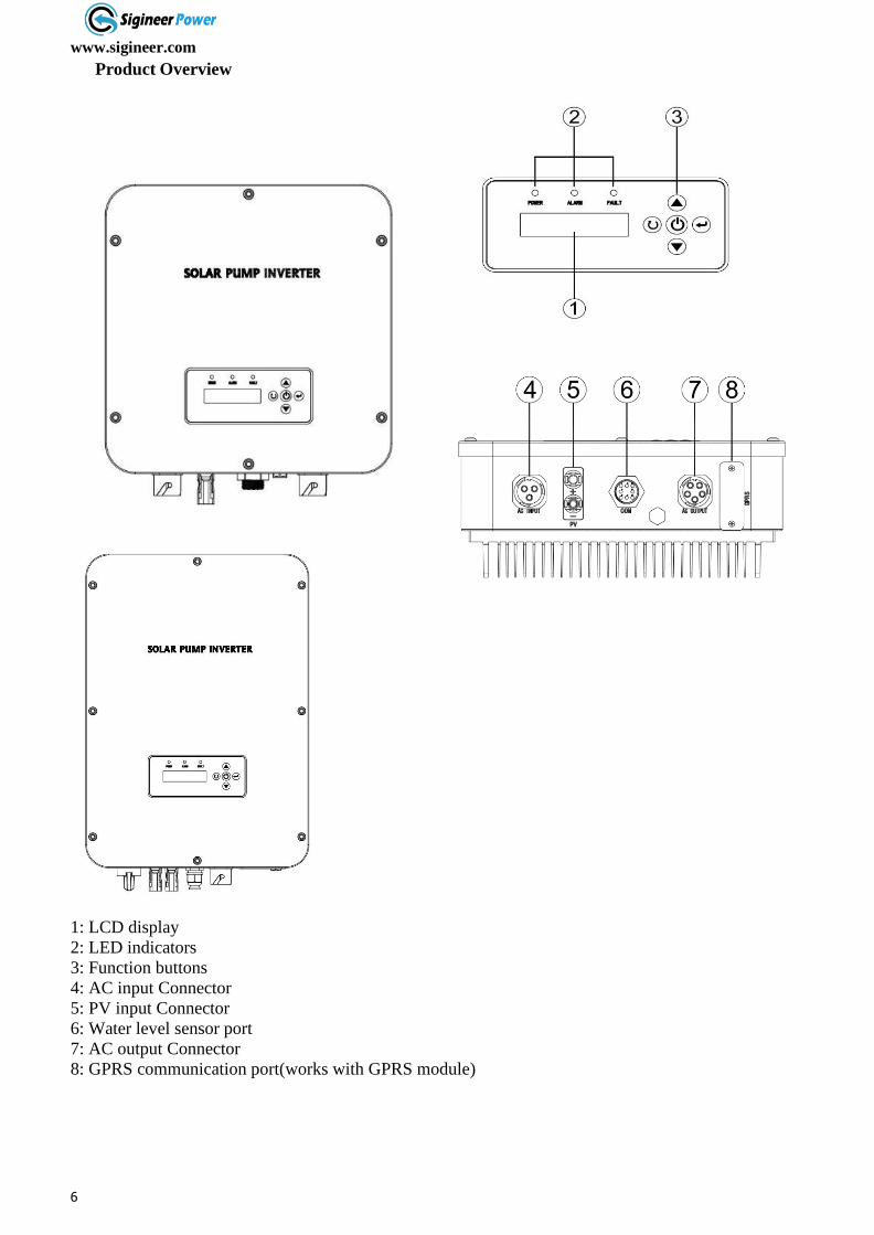
Product Overview
1. LCD display
2. LED indicators
3. Function buttons
4. AC input
5. PV input
1: LCD display
2: LED indicators
3: Function buttons
4: AC input Connector
5: PV input Connector
6: Water level sensor port
7: AC output Connector
8: GPRS communication port(works with GPRS module)
www.sigineer.com
7
Installation
Unpacking and Inspection
Before installation, please inspect the unit. Be sure that nothing inside the package is damaged.
You should have received the following items inside of package:
⚫ The unit x 1
⚫ User manual x 1
⚫ Accessory(Connector) x 1 set
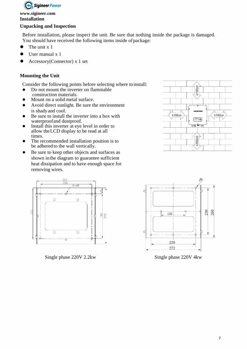
Mounting the Unit
Consider the following points before selecting where to install: ⚫ Do not mount the inverter on flammable
construction materials. ⚫ Mount on a solid metal surface. ⚫ Avoid direct sunlight. Be sure the environment
is shady and cool. ⚫ Be sure to install the inverter into a box with
waterproof and dustproof. ⚫ Install this inverter at eye level in order to
allow the LCD display to be read at all times.
⚫ The recommended installation position is to be adhered to the wall vertically.
⚫ Be sure to keep other objects and surfaces as
shown in the diagram to guarantee sufficient
heat dissipation and to have enough space for
removing wires.
Single phase 220V 2.2kw Single phase 220V 4kw
www.sigineer.com
8
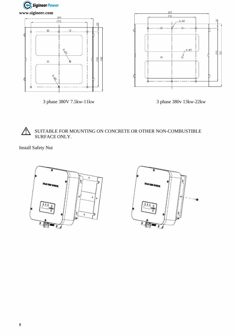
3 phase 380V 7.5kw-11kw 3 phase 380v 13kw-22kw
SUITABLE FOR MOUNTING ON CONCRETE OR OTHER NON-COMBUSTIBLE
SURFACE ONLY.
Install Safety Nut
www.sigineer.com
9
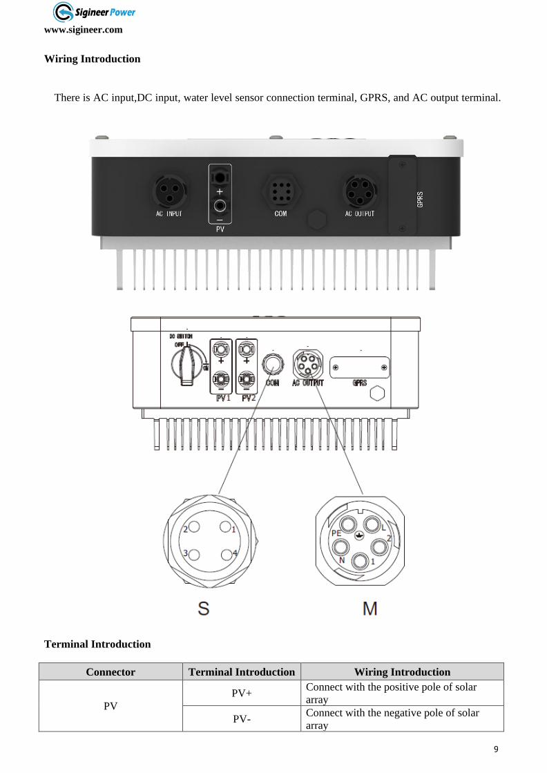
Wiring Introduction
There is AC input,DC input, water level sensor connection terminal, GPRS, and AC output terminal.
Terminal Introduction
Connector Terminal Introduction Wiring Introduction
PV
PV+ Connect with the positive pole of solar
array
PV- Connect with the negative pole of solar
array
www.sigineer.com
10
AC Input For 220V(Available
only on 2.2KW)
L Connect with power grid L phase
N Connect with power grid N phase
PE Connect with protective ground wire
AC Output
(3 PH motor connect 1,2,L)
(1 PH motor connect 1,L)
1 Connect with motor U phase
2 Connect with motor V phase
L Connect with motor W phase
PE Connect with protective ground wire
COMMUNICATION Port
1 Connect with Sensor 2 of water tank
2 Connect with Sensor 2 of water tank
3 /
4 /
5 Connect with Sensor 1 of water well
6 Connect with Sensor 1 of water well
GPRS Port
1 +5V
2 TXD-232
3 RXD-232
4 GND
For models with AC input, it only accepts 220Vac voltage on the L and N pins, this power can be from
single phase L+N, split phase L+L or 2 hotlines of 3 phase power systems.
The communication port works with water sensors, the inverter will stop with when the sensor signal is
“Closed”.
Warning: The places of input sockets of DC positive pole and negative pole of different models are
different.
Warning: The signal marshalling sequence of AC output sockets of different models are
different.
Wanting: It is recoimmended to wire the AC output PE to ground, the inverter can still operate without
ground, special precaustion should be taken.
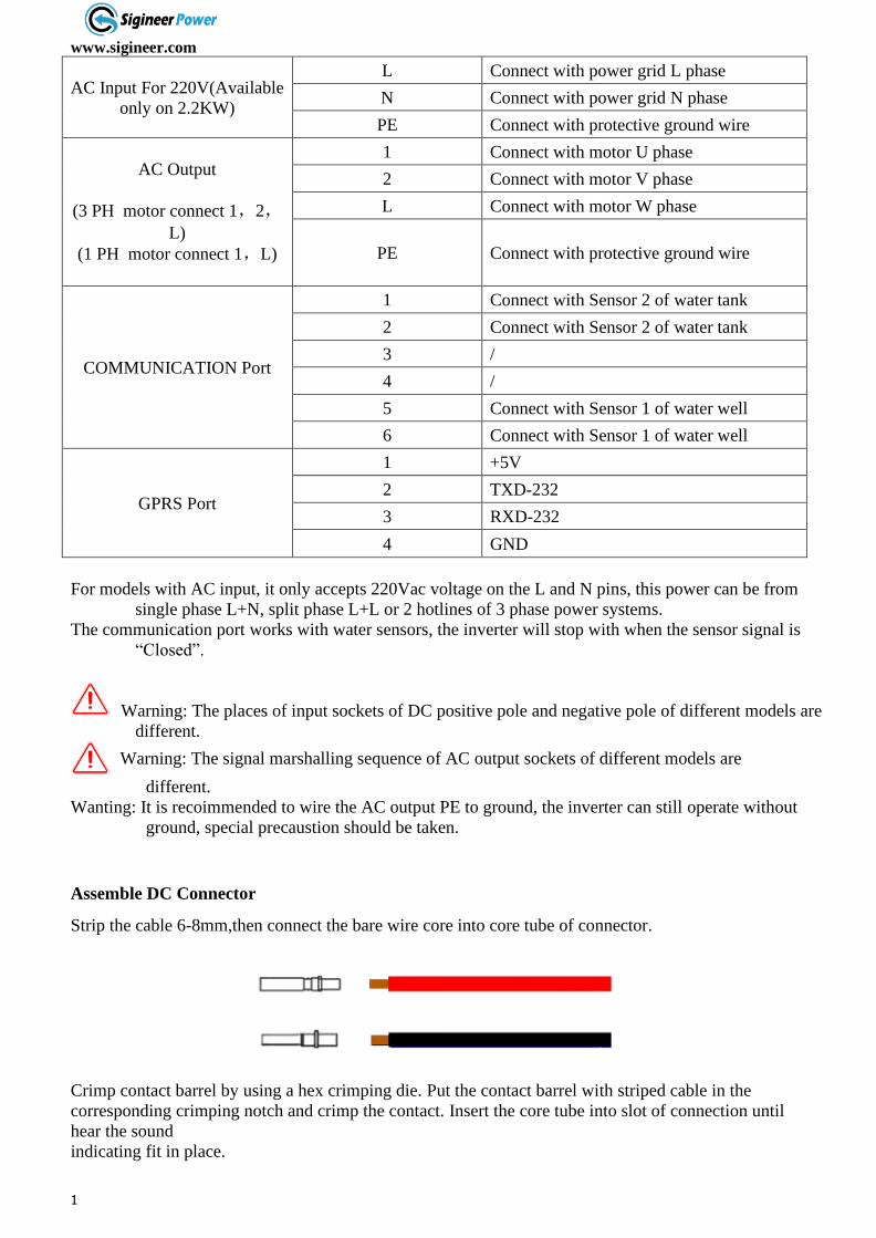
Assemble DC Connector
Strip the cable 6-8mm,then connect the bare wire core into core tube of connector.
Crimp contact barrel by using a hex crimping die. Put the contact barrel with striped cable in the
corresponding crimping notch and crimp the contact. Insert the core tube into slot of connection until
hear the sound
indicating fit in place.
www.sigineer.com
11
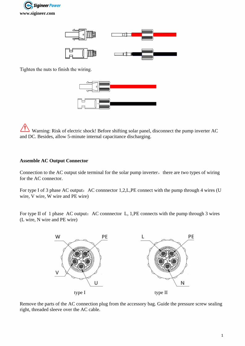
Tighten the nuts to finish the wiring.
Warning: Risk of electric shock! Before shifting solar panel, disconnect the pump inverter AC
and DC. Besides, allow 5-minute internal capacitance discharging.
Assemble AC Output Connector
Connection to the AC output side terminal for the solar pump inverter,there are two types of wiring
for the AC connector.
For type I of 3 phase AC output:AC connnector 1,2,L,PE connect with the pump through 4 wires (U
wire, V wire, W wire and PE wire)
For type II of 1 phase AC output:AC connnector L, 1,PE connects with the pump through 3 wires
(L wire, N wire and PE wire)
type I type II
Remove the parts of the AC connection plug from the accessory bag. Guide the pressure screw sealing
right, threaded sleeve over the AC cable.
www.sigineer.com
12
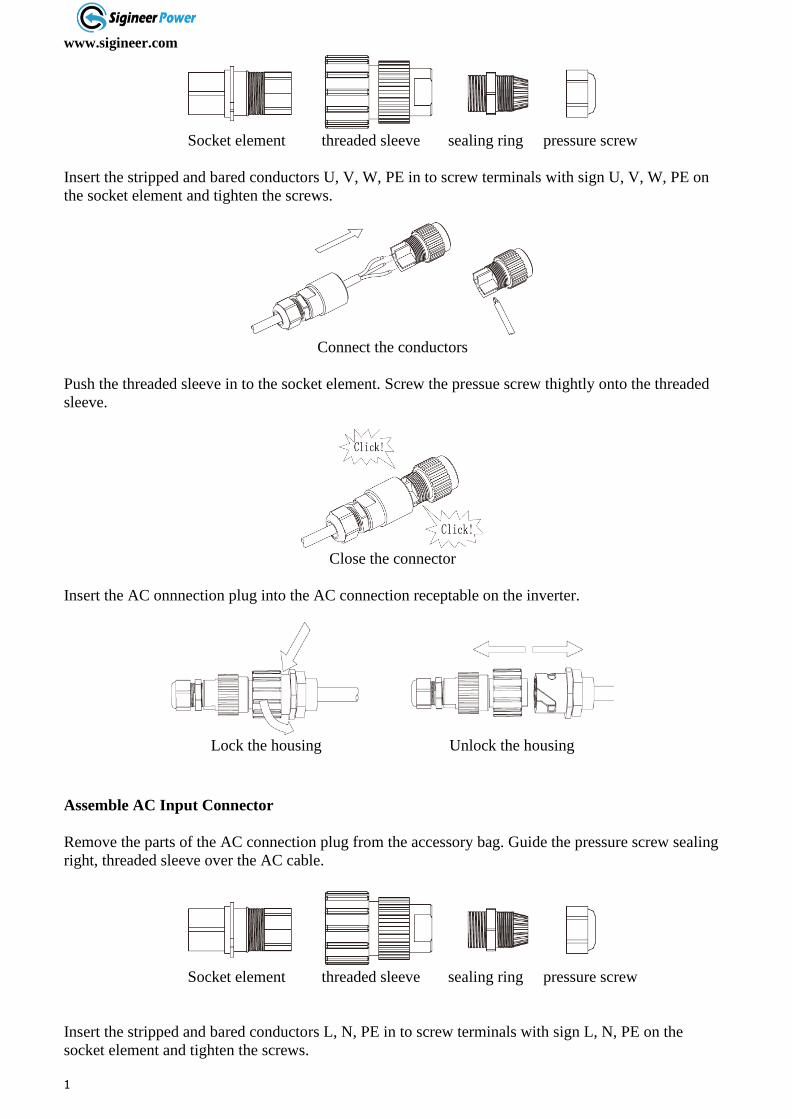
Socket element threaded sleeve sealing ring pressure screw
Insert the stripped and bared conductors U, V, W, PE in to screw terminals with sign U, V, W, PE on
the socket element and tighten the screws.
Connect the conductors
Push the threaded sleeve in to the socket element. Screw the pressue screw thightly onto the threaded
sleeve.
Close the connector
Insert the AC onnnection plug into the AC connection receptable on the inverter.
Lock the housing Unlock the housing
Assemble AC Input Connector
Remove the parts of the AC connection plug from the accessory bag. Guide the pressure screw sealing
right, threaded sleeve over the AC cable.
Socket element threaded sleeve sealing ring pressure screw
Insert the stripped and bared conductors L, N, PE in to screw terminals with sign L, N, PE on the
socket element and tighten the screws.

www.sigineer.com
13
Connect the conductors
Push the threaded sleeve in to the socket element. Screw the pressure screw tightly onto the threaded
sleeve.
Close the connector
Insert the AC connnection plug into the AC connection receptacle on the inverter.
Lock the housing Unlock the housing
Assemble sensor Connector
The series inverter has one 8 Pin signal connector,signal cable ports:
Pin number Wiring Introduction
1 Connect with sensor of tank
2 Connect with sensor of tank
3 /
4 /
5 Connect with sensor of well
6 Connect with sensor of well
www.sigineer.com
14
7 /
8 /
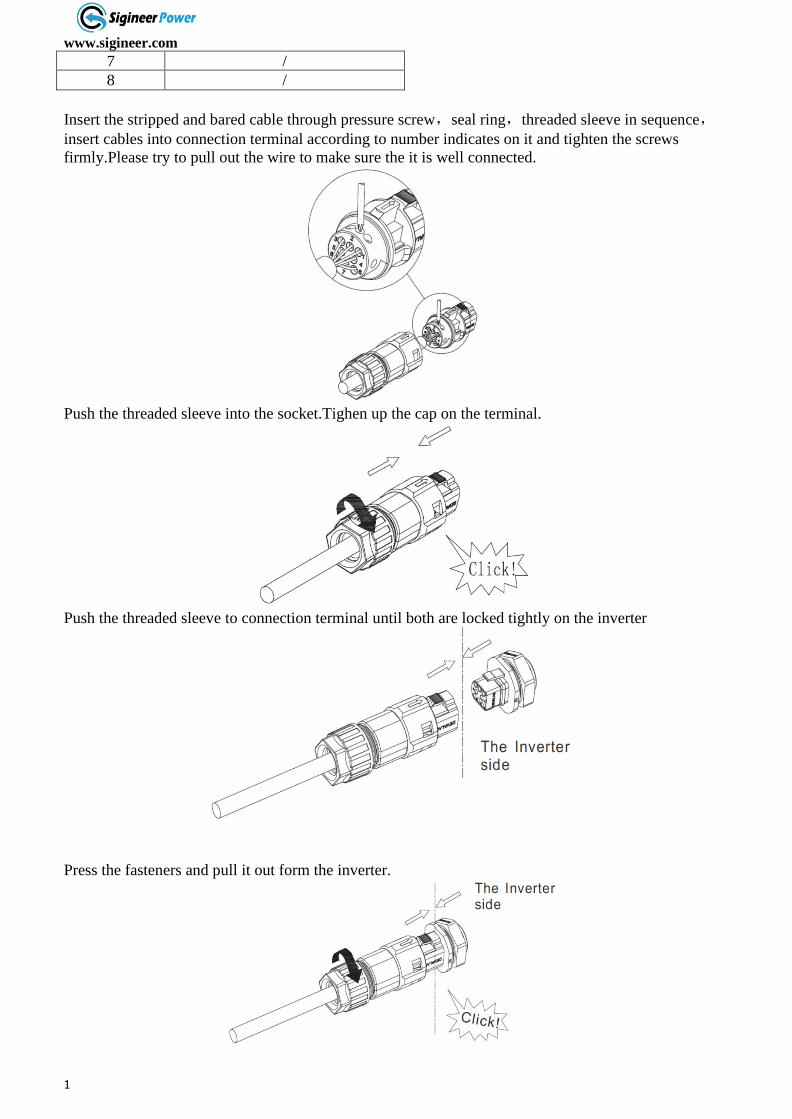
Insert the stripped and bared cable through pressure screw,seal ring,threaded sleeve in sequence,insert cables into connection terminal according to number indicates on it and tighten the screws
firmly.Please try to pull out the wire to make sure the it is well connected.
Push the threaded sleeve into the socket.Tighen up the cap on the terminal.
Push the threaded sleeve to connection terminal until both are locked tightly on the inverter
Press the fasteners and pull it out form the inverter.

www.sigineer.com
15
Wiring of Water Level Sensor
Notice: connect water level sensor 1 and detect water shortage. Respectively connect two signal
lines of sensor with 5 and 6 of COM terminal. When water level sensor 1 detects that the water level
of well is lower than the level set by sensor, the pump inverter will delay for 5s, then turn off output
protecting pump. The water level recovers. Wait for 20s, then the pump inverter re-works normally.
Notice: connect water level sensor 2 to defect whether water is full. Connect two signal lines of
sensor with 1 and 2 of COM terminal. When water level sensor 2 detects that the water level of water
tank exceeds the level set by sensor, the pump inverter delays for 5s and turns off output; when water
level is lower than set level, wait for 20s, then pump inverter re-starts to work normally.
Utility Grid
Connect 1 and 2
Water Tube
AC Output
Connect 5 and 6
Water Level Sensor 2
Water Pump
Water Level Sensor 1
Water Tank
Solar Panel
Water Well
www.sigineer.com
16
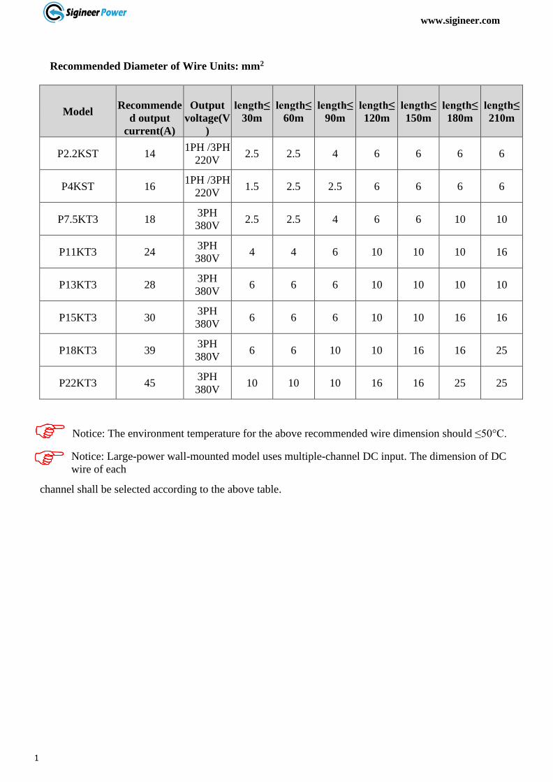
Recommended Diameter of Wire Units: mm2
Model
Recommende
d output
current(A)
Output
voltage(V
)
length≤
30m
length≤
60m
length≤
90m
length≤
120m
length≤
150m
length≤
180m
length≤
210m
P2.2KST 14 1PH /3PH
220V 2.5 2.5 4 6 6 6 6
P4KST 16 1PH /3PH
220V 1.5 2.5 2.5 6 6 6 6
P7.5KT3 18 3PH
380V 2.5 2.5 4 6 6 10 10
P11KT3 24 3PH
380V 4 4 6 10 10 10 16
P13KT3 28 3PH
380V 6 6 6 10 10 10 10
P15KT3 30 3PH
380V 6 6 6 10 10 16 16
P18KT3 39 3PH
380V 6 6 10 10 16 16 25
P22KT3 45 3PH
380V 10 10 10 16 16 25 25
Notice: The environment temperature for the above recommended wire dimension should ≤50°C.
Notice: Large-power wall-mounted model uses multiple-channel DC input. The dimension of DC
wire of each
channel shall be selected according to the above table.

www.sigineer.com
17
Operation
Display Panel
Solar pump inverter uses LCD operation panel. The operation panel is shown in the figure, including 3
LED lights, LCD display and 5 keys.
Indicator and Key Name Function Introduction
POWER
System
running
indicator
Green LED on, inverter is running
ALARM Warning
indicator
Yello
w
LED on, warning or LED flashing in
auto operation mode
FAULT Failure
indicator Red LED on, system failure
Operation /
Stop Key
1. Press for a short time, then the inverter starts
control;
2. Press for 2s, then inverter stops control.
Confirm /
Programming
Key
1. Press for a short time to enter programming
mode. After altering parameter, “press for a short
time” to confirm the alteration
2. Press for 2s to enter the programming menu.
Increment Key
1. When control parameter displays state, increase
parameter number or parameter value;
2. When operation displays data state, according
to operation mode, increase output frequency or
display current operation data.
Decrement
Key
1. When control parameter displays state, press for
a short time to decrease parameter number or
parameter value.
2. When operation shows data state, according to
operation mode, decrease output frequency or
display current operation data.
Return Key Return the initial display
www.sigineer.com
18
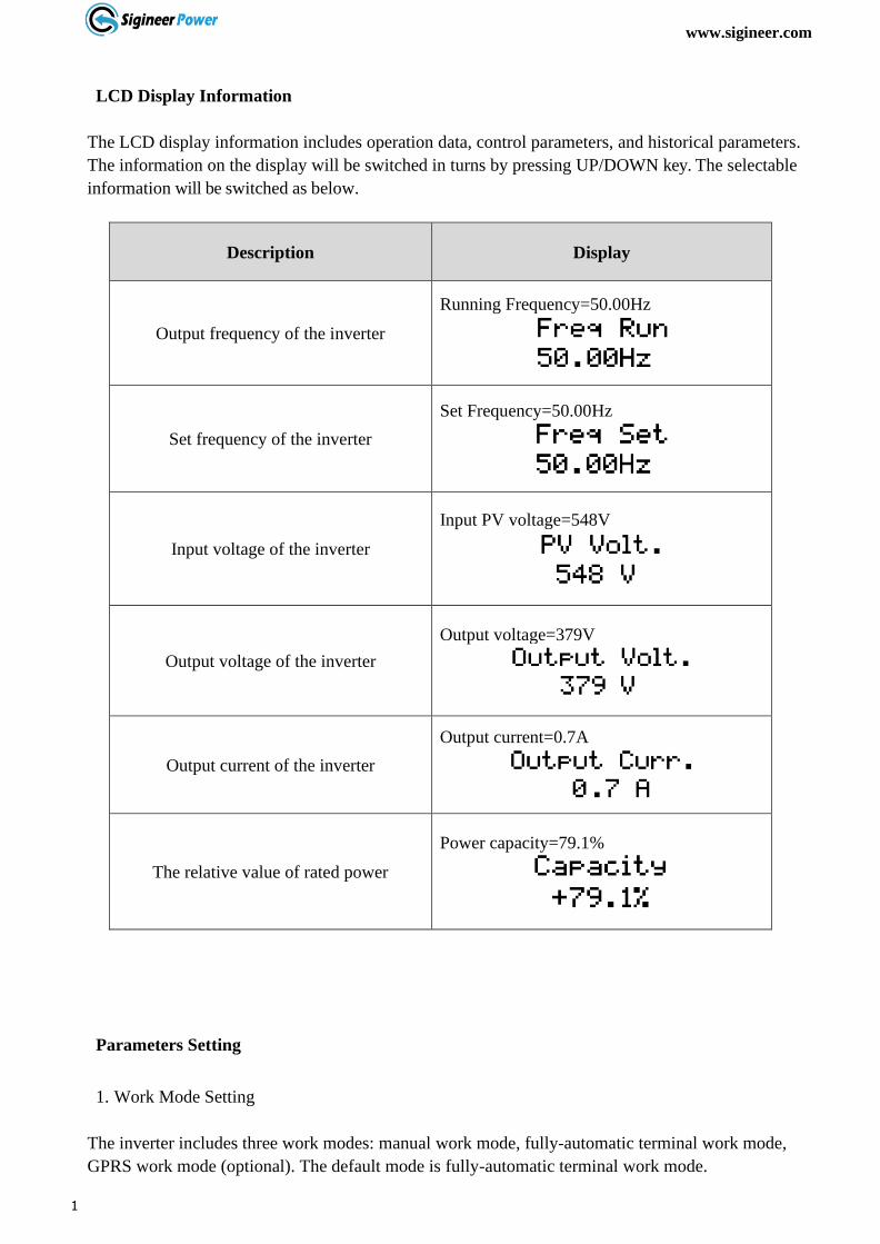
LCD Display Information
The LCD display information includes operation data, control parameters, and historical parameters.
The information on the display will be switched in turns by pressing UP/DOWN key. The selectable
information will be switched as below.
Description Display
Output frequency of the inverter
Running Frequency=50.00Hz
Set frequency of the inverter
Set Frequency=50.00Hz
Input voltage of the inverter
Input PV voltage=548V
Output voltage of the inverter
Output voltage=379V
Output current of the inverter
Output current=0.7A
The relative value of rated power
Power capacity=79.1%
Parameters Setting
1. Work Mode Setting
The inverter includes three work modes: manual work mode, fully-automatic terminal work mode,
GPRS work mode (optional). The default mode is fully-automatic terminal work mode.

www.sigineer.com
19
a. Manual work mode: menu P00. Setting P00.01=0. Press key to operate. Press key for 2s,
then the inverter stop working.
b. Fully-automatic terminal work mode: menu P00. Setting P00.01=1. When sunlight is strong enough,
the inverter will automatically trace maximum power point.
c. GPRS work mode (optional): menu P00. Setting P00.01=2. Under this mode, combined with
cellphone number, send messages to set startup, shutdown(enter sleep mode), parameter inquiry,
etc.
Description Display
Initial status: non-historical data display
Enter the main parameter modification interface
for long press 2s for Enter key
P00 parameter group, Work Mode group
Press Enter key , to enter view the P00.01
P00.01 sub parameter group
Press Enter key , to enter the P00.01(the
factory set is 1)
00.01, value =1 (Default), terminal work mode
Use Down key , edite it to 0 (controlled by
keyboard)
P00.01, value =0, manual work mode
Press Enter key , to save the parameter
value and display Set OK!
Present: Set OK!
2. Rated parameters setting for the motor
Before setting the parameters, please make sure all the wiring is correct.
www.sigineer.com
20
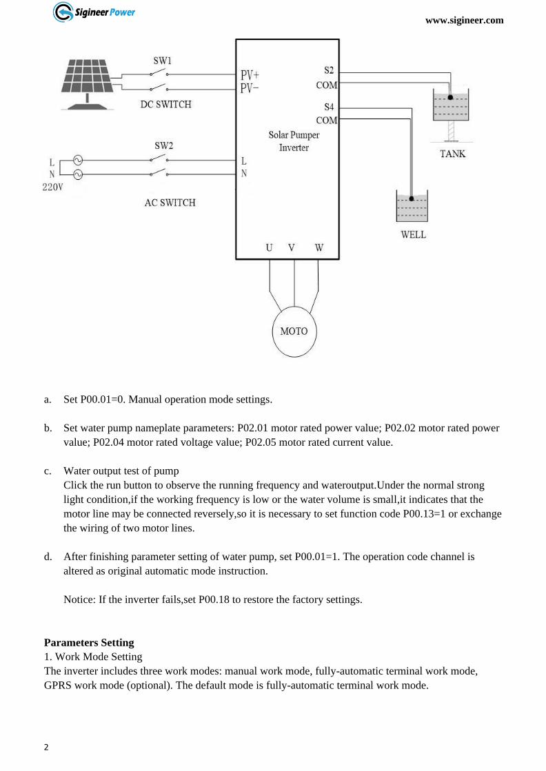
a. Set P00.01=0. Manual operation mode settings.
b. Set water pump nameplate parameters: P02.01 motor rated power value; P02.02 motor rated power
value; P02.04 motor rated voltage value; P02.05 motor rated current value.
c. Water output test of pump
Click the run button to observe the running frequency and wateroutput.Under the normal strong
light condition,if the working frequency is low or the water volume is small,it indicates that the
motor line may be connected reversely,so it is necessary to set function code P00.13=1 or exchange
the wiring of two motor lines.
d. After finishing parameter setting of water pump, set P00.01=1. The operation code channel is
altered as original automatic mode instruction.
Notice: If the inverter fails,set P00.18 to restore the factory settings.
Parameters Setting
1. Work Mode Setting
The inverter includes three work modes: manual work mode, fully-automatic terminal work mode,
GPRS work mode (optional). The default mode is fully-automatic terminal work mode.

www.sigineer.com
21
Parameter Setting (Example)
Click the back
key to enter the
main page
Click the
key
again to
set OK
Press the enter key
again Change the default
value of 1 to 0
Work mode
P00
Enter the main parameter
modification interface for long
press 2s for Enter key
Work mode
P00.01
Press Enter key ,to
enter view the P00.01
Work mode
0
0:manual mode
1:automatic mode
2:GPRS mode
Work mode
Set OK
Freq Run
50.00HZ
www.sigineer.com
22
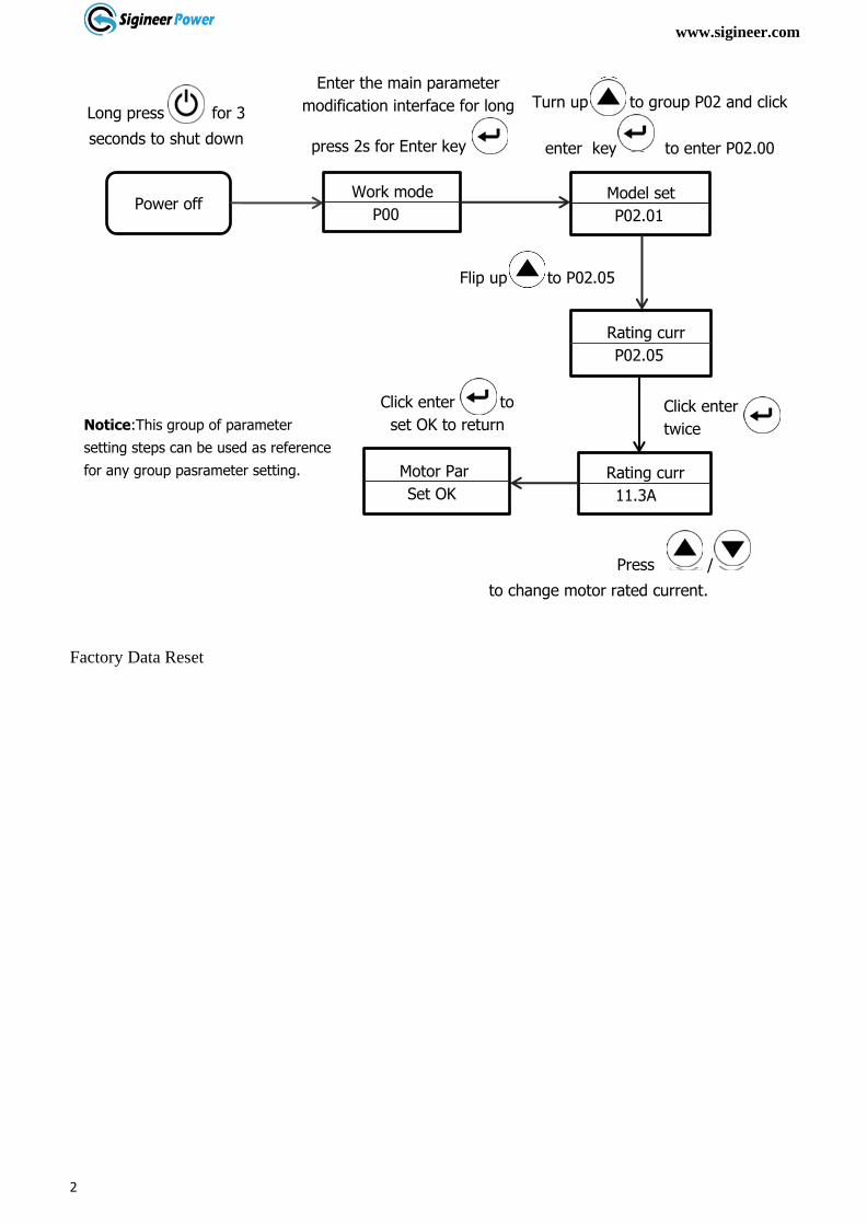
Factory Data Reset
Click enter to
set OK to return
Power off
Long press for 3
seconds to shut down
Work mode
P00
Enter the main parameter
modification interface for long
press 2s for Enter key
Model set
P02.01
Turn up to group P02 and click
enter key to enter P02.00
Rating curr
P02.05
Flip up to P02.05
Rating curr
11.3A
Click enter
twice
Press /
to change motor rated current.
Motor Par
Set OK
Notice:This group of parameter
setting steps can be used as reference
for any group pasrameter setting.
www.sigineer.com
23
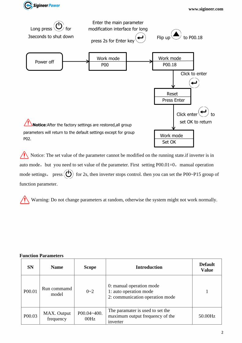
Notice: The set value of the parameter cannot be modified on the running state.if inverter is in
auto mode,but you need to set value of the parameter. First setting P00.01=0,manual operation
mode settings, press for 2s, then inverter stops control. then you can set the P00~P15 group of
function parameter.
Warning: Do not change parameters at random, otherwise the system might not work normally.
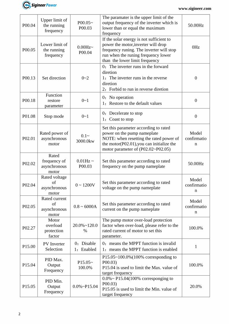
Function Parameters
SN Name Scope Introduction Default
Value
P00.01 Run commamd
model 0~2
0: manual operation mode
1: auto operation mode
2: communication operation mode
1
P00.03 MAX. Output
frequency
P00.04~400.
00Hz
The paramater is used to set the
maximum output frequency of the
inverter
50.00Hz
Click enter to
set OK to return
Click to enter
Power off
Long press for
3seconds to shut down
Work mode
P00
Work mode
P00.18
Enter the main parameter
modification interface for long
press 2s for Enter key Flip up to P00.18
Reset
Press Enter
Work mode
Set OK
Notice:After the factory settings are restored,all group
parameters will return to the default settings except for group
P02.
www.sigineer.com
24
P00.04
Upper limit of
the running
frequency
P00.05~
P00.03
The paramater is the upper limit of the
output frequency of the inverter which is
lower than or equal the maximum
frequency
50.00Hz
P00.05
Lower limit of
the running
frequency
0.00Hz~
P00.04
If the solar energy is not sufficient to
power the motor,inverter will drop
frequency runing. The inverter will stop
run when the runing frequency lower
than the lower limit frequency
0Hz
P00.13 Set direction 0~2
0:The inverter runs in the forward
diretion
1:The inverter runs in the reverse
diretion
2:Forbid to run in reverse diretion
0
P00.18
Function
restore
parameter
0~1 0:No operation
1:Restore to the default values 0
P01.08 Stop mode 0~1 0:Decelerate to stop
1:Coast to stop 0
P02.01
Rated power of
asynchronous
motor
0.1~
3000.0kw
Set this parameter according to rated
power on the pump nameplate
NOTE: when resetting the rated power of
the motor(P02.01),you can initialize the
motor parameter of (P02.02~P02.05)
Model
confirmatio
n
P02.02
Rated
frequency of
asynchronous
motor
0.01Hz ~
P00.03
Set this parameter according to rated
frequency on the pump nameplate 50.00Hz
P02.04
Rated voltage
of
asynchronous
motor
0 ~ 1200V Set this parameter according to rated
voltage on the pump nameplate
Model
confirmatio
n
P02.05
Rated current
of
asynchronous
motor
0.8 ~ 6000A Set this parameter according to rated
current on the pump nameplate
Model
confirmatio
n
P02.27
Motor
overload
protection
factor
20.0%~120.0
%
The pump motor over-load protection
factor when over-load, please refer to the
rated current of motor to set this
parameter.
100.0%
P15.00 PV Inverter
Selection
0:Disable
1:Enabled
0:means the MPPT function is invalid
1:means the MPPT function is enabled 1
P15.04
PID Max.
Output
Frequency
P15.05~
100.0%
P15.05~100.0%(100% corresponding to
P00.03)
P15.04 is used to limit the Max. value of
target frequency
100.0%
P15.05
PID Min.
Output
Frequency
0.0%~P15.04
0.0%~ P15.04(100% corresponging to
P00.03)
P15.05 is used to limit the Min. value of
target frequency
20.0%
www.sigineer.com
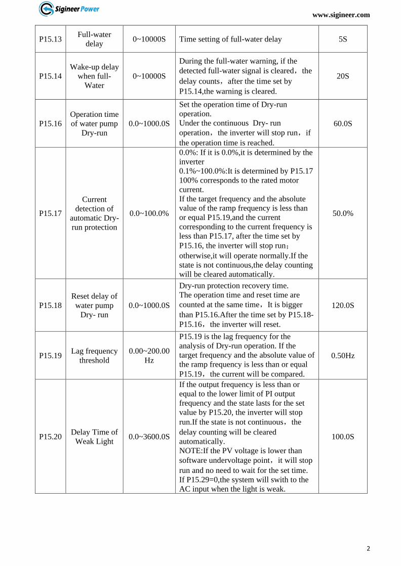
25
P15.13 Full-water
delay 0~10000S Time setting of full-water delay 5S
P15.14
Wake-up delay
when full-
Water
0~10000S
During the full-water warning, if the
detected full-water signal is cleared,the
delay counts,after the time set by
P15.14,the warning is cleared.
20S
P15.16
Operation time
of water pump
Dry-run
0.0~1000.0S
Set the operation time of Dry-run
operation.
Under the continuous Dry- run
operation,the inverter will stop run,if
the operation time is reached.
60.0S
P15.17
Current
detection of
automatic Dry-
run protection
0.0~100.0%
0.0%: If it is 0.0%,it is determined by the
inverter
0.1%~100.0%:It is determined by P15.17
100% corresponds to the rated motor
current.
If the target frequency and the absolute
value of the ramp frequency is less than
or equal P15.19,and the current
corresponding to the current frequency is
less than P15.17, after the time set by
P15.16, the inverter will stop run;otherwise,it will operate normally.If the
state is not continuous,the delay counting
will be cleared automatically.
50.0%
P15.18
Reset delay of
water pump
Dry- run
0.0~1000.0S
Dry-run protection recovery time.
The operation time and reset time are
counted at the same time,It is bigger
than P15.16.After the time set by P15.18-
P15.16,the inverter will reset.
120.0S
P15.19 Lag frequency
threshold
0.00~200.00
Hz
P15.19 is the lag frequency for the
analysis of Dry-run operation. If the
target frequency and the absolute value of
the ramp frequency is less than or equal
P15.19,the current will be compared.
0.50Hz
P15.20 Delay Time of
Weak Light 0.0~3600.0S
If the output frequency is less than or
equal to the lower limit of PI output
frequency and the state lasts for the set
value by P15.20, the inverter will stop
run.If the state is not continuous,the
delay counting will be cleared
automatically.
NOTE:If the PV voltage is lower than
software undervoltage point,it will stop
run and no need to wait for the set time.
If P15.29=0,the system will swith to the
AC input when the light is weak.
100.0S
www.sigineer.com
26
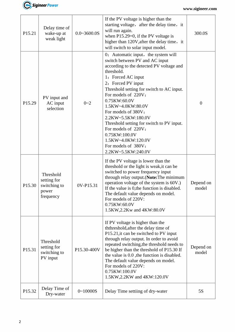
P15.21
Delay time of
wake-up at
weak light
0.0~3600.0S
If the PV voltage is higher than the
starting voltage,after the delay time,it
will run again.
when P15.29=0, if the PV voltage is
higher than 120V,after the delay time,it
will switch to solar input model.
300.0S
P15.29
PV input and
AC input
selection
0~2
0:Automatic input,the system will
switch between PV and AC input
according to the detected PV voltage and
threshold.
1:Forced AC input
2:Forced PV input
Threshold setting for switch to AC input.
For models of 220V:
0.75KW:60.0V
1.5KW~4.0KW:80.0V
For models of 380V:
2.2KW~5.5KW:180.0V
Threshold setting for switch to PV input.
For models of 220V:
0.75KW:100.0V
1.5KW~4.0KW:120.0V
For models of 380V:
2.2KW~5.5KW:240.0V
0
P15.30
Threshold
setting for
switching to
power
frequency
0V-P15.31
If the PV voltage is lower than the
threshold or the light is weak,it can be
switched to power frequency input
through relay output.(Note:The minimum
operation voltage of the system is 60V.)
If the value is 0,the function is disabled.
The default value depends on model.
For models of 220V:
0.75KW:60.0V
1.5KW,2.2Kw and 4KW:80.0V
Depend on
model
P15.31
Threshold
setting for
switching to
PV input
P15.30-400V
If PV voltage is higher than the
ththreshold,after the delay time of
P15.21,it can be switched to PV input
through relay output. In order to avoid
repeated switching,the threshold needs to
be higher than the threshold of P15.30 If
the value is 0.0 ,the function is disabled.
The default value depends on model.
For models of 220V:
0.75KW:100.0V
1.5KW,2.2KW and 4KW:120.0V
Depend on
model
P15.32 Delay Time of
Dry-water 0~10000S Delay Time settiing of dry-water 5S
www.sigineer.com
27
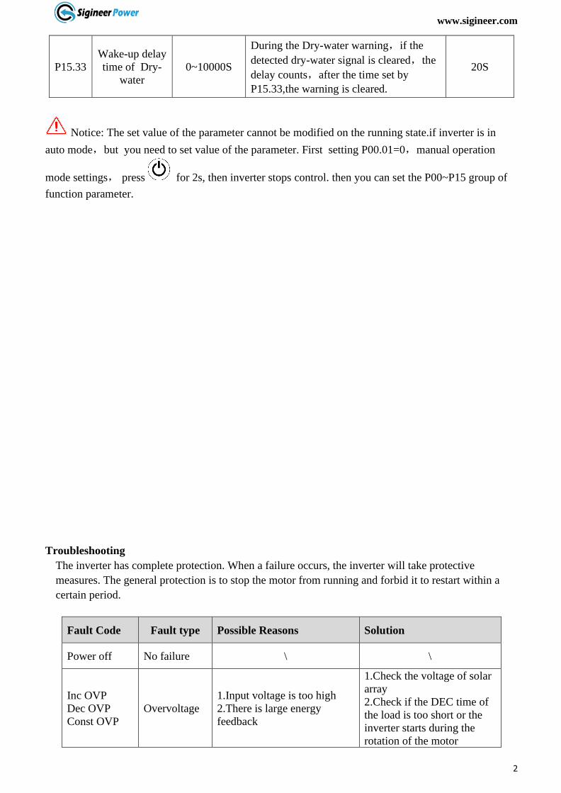
P15.33
Wake-up delay
time of Dry-
water
0~10000S
During the Dry-water warning,if the
detected dry-water signal is cleared,the
delay counts,after the time set by
P15.33,the warning is cleared.
20S
Notice: The set value of the parameter cannot be modified on the running state.if inverter is in
auto mode,but you need to set value of the parameter. First setting P00.01=0,manual operation
mode settings, press for 2s, then inverter stops control. then you can set the P00~P15 group of
function parameter.
Troubleshooting
The inverter has complete protection. When a failure occurs, the inverter will take protective
measures. The general protection is to stop the motor from running and forbid it to restart within a
certain period.
Fault Code Fault type Possible Reasons Solution
Power off No failure \ \
Inc OVP
Dec OVP
Const OVP
Overvoltage
1.Input voltage is too high
2.There is large energy
feedback
1.Check the voltage of solar
array
2.Check if the DEC time of
the load is too short or the
inverter starts during the
rotation of the motor

www.sigineer.com
28
DC Bus low
Voltage Undervoltage
1.Input voltage is too low;
2.Illumination intensity is too
weak
Check the voltage of solar
array
Inc OCP
Dec OCP
Const OCP
Overcurrent
1.The load of pump is too
large;
2.The voltage of solar array is
too low;
3.The motor wiring is too
long
4.The power of the inverter is
too low
5.The grounding is short
circuited or the output is
phase loss
1.Replace for a smaller
pump;
2.Check voltage of solar
array;
3.Shorten the wiring
between inverter and motor
4.Select the inverter with a
larger power
5. Check if the load is short
curcuited
Pump
Overload
Water pump
is overload
1.The motor setting rated
current is incorrent
2.Input voltage is too low
3.Improper motor’s overload
protection threshold
4.Motor block or sudden
change of load
1.Reset the rated cueernt of
the motor
2.Inspect the input power
supply
3.Set proper motor rated
current
4.Check the load and adjust
torque boost
Overload VF Inverter is
overload
1.Acc time is too short
2.Restart the rotating motor
3.Input voltage is too low
4.the load is too heavy
1.Increase the Acc time
2.Avoid restart after power
off
3.Check the power supply
4.Select bigger capacity
inverter
IGBT short Module
overcurrent
Output short circuit or
grounding module damage
1.Check the wiring
2.Get after-sells support
Inv Overtemp
Module is
over-
temperature
1.Air flue is blocked
2.Environment temperature is
too high
3.The time of overload
runing is too long.
4.Control board abnormal
1.Clean air flue or improve
ventilation
2.Degree the environment
temperature
3.Select a proper motor
4.Ask for support Rec Overtemp
Module is
over-
temperature
Phase out loss Output
default phase
Phase loss of U,V,W output
(or a serious unbalance in
3phase input)
1.Check the output
distribution
2.Check the motor and cable
3.Get after-sells support
Shortcut GND
1
Grounding
short circuit
The output line may be
connected with ground Check the wiring
Curr fault
Current
detection
failure
1.The control board
connection is in poor contact
2.The hall component is
damaged
The magnifying circuit is
abnormal
3.The magnifying circuit is
abnormal
1.Check the connector and
rewire
2.replace the hall component
3.replace the main control
panel
4.Get after-sells support

www.sigineer.com
29
Lack load
when set dry-
power
(P15.15)is
not 0.0%
Water pump
conducts
“dry-
operation”
1.Water pump’s connection
wires are all open circuit.
2.Water sources are lacking
of water
1.Check P15.15 parameter
2.Check whether the water
pump wiring condition and
water pump power meet the
requirements of inverter
capacity
Lack Water Water
shortage Water shortage warning
1.If the water empty alarm
function is enabled,the
device automatically stops
after the water empty alarm
remains for a certain period
of time,and no processing
is needed.
2. If the water empty alarm
function is not enabled,check whether there are
terminals misconnected
Water Full Water full Water full warning
1.If the water full alarm
function is enabled,the
device automatically stops
after the water empty alarm
remains for a certain period
of time,and no processing
is needed.
2. If the water empty alarm
function is not enabled,check whether there are
terminals misconnected
Com Fault Communicati
on failure Device or circuit damage
Reset
Get after-sells support
Warning: Try to find out the failure reason before your try reset. If it can’t reset or suffers
failure again
after reset, please try find out the reason first. Continuously resetting could damage the inverter.
www.sigineer.com
30
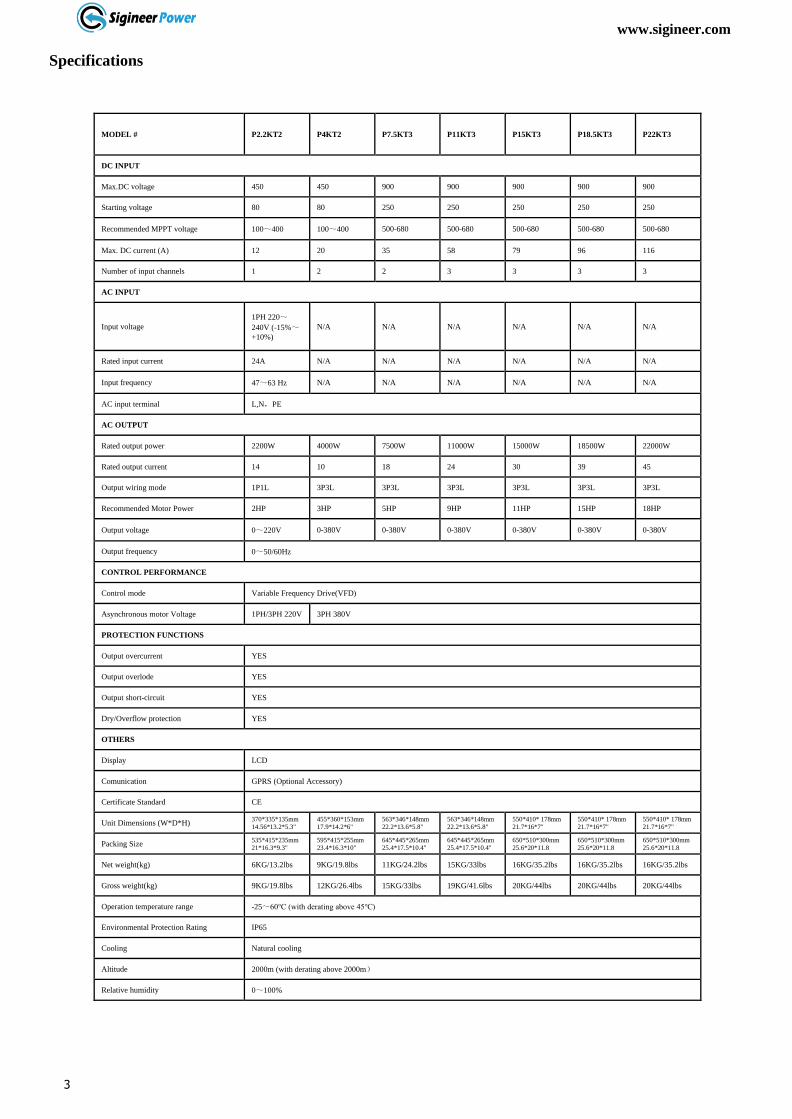
Specifications
MODEL # P2.2KT2 P4KT2 P7.5KT3 P11KT3 P15KT3 P18.5KT3 P22KT3
DC INPUT
Max.DC voltage 450 450 900 900 900 900 900
Starting voltage 80 80 250 250 250 250 250
Recommended MPPT voltage 100~400 100~400 500-680 500-680 500-680 500-680 500-680
Max. DC current (A) 12 20 35 58 79 96 116
Number of input channels 1 2 2 3 3 3 3
AC INPUT
Input voltage
1PH 220~
240V (-15%~+10%)
N/A N/A N/A N/A N/A N/A
Rated input current 24A N/A N/A N/A N/A N/A N/A
Input frequency 47~63 Hz N/A N/A N/A N/A N/A N/A
AC input terminal L,N,PE
AC OUTPUT
Rated output power 2200W 4000W 7500W 11000W 15000W 18500W 22000W
Rated output current 14 10 18 24 30 39 45
Output wiring mode 1P1L 3P3L 3P3L 3P3L 3P3L 3P3L 3P3L
Recommended Motor Power 2HP 3HP 5HP 9HP 11HP 15HP 18HP
Output voltage 0~220V 0-380V 0-380V 0-380V 0-380V 0-380V 0-380V
Output frequency 0~50/60Hz
CONTROL PERFORMANCE
Control mode Variable Frequency Drive(VFD)
Asynchronous motor Voltage 1PH/3PH 220V 3PH 380V
PROTECTION FUNCTIONS
Output overcurrent YES
Output overlode YES
Output short-circuit YES
Dry/Overflow protection YES
OTHERS
Display LCD
Comunication GPRS (Optional Accessory)
Certificate Standard CE
Unit Dimensions (W*D*H) 370*335*135mm
14.56*13.2*5.3"
455*360*153mm
17.9*14.2*6"
563*346*148mm
22.2*13.6*5.8"
563*346*148mm
22.2*13.6*5.8"
550*410* 178mm
21.7*16*7"
550*410* 178mm
21.7*16*7"
550*410* 178mm
21.7*16*7"
Packing Size 535*415*235mm
21*16.3*9.3"
595*415*255mm
23.4*16.3*10"
645*445*265mm
25.4*17.5*10.4"
645*445*265mm
25.4*17.5*10.4"
650*510*300mm
25.6*20*11.8
650*510*300mm
25.6*20*11.8
650*510*300mm
25.6*20*11.8
Net weight(kg) 6KG/13.2lbs 9KG/19.8lbs 11KG/24.2lbs 15KG/33lbs 16KG/35.2lbs 16KG/35.2lbs 16KG/35.2lbs
Gross weight(kg) 9KG/19.8lbs 12KG/26.4lbs 15KG/33lbs 19KG/41.6lbs 20KG/44lbs 20KG/44lbs 20KG/44lbs
Operation temperature range -25~60℃ (with derating above 45℃)
Environmental Protection Rating IP65
Cooling Natural cooling
Altitude 2000m (with derating above 2000m)
Relative humidity 0~100%

www.sigineer.com
31
SAVE THIS MANUAL!
READ THIS MANUAL BEFORE INSTALLATION, IT
CONTAINS IMPORTANT SAFETY, INSTALLATION AND
OPERATING INSTRUCTIONS. KEEP IT IN A SAFE PLACE
FOR FUTURE REFERENCE.
Sigineer Power Limited
Email: [email protected]
TEL: +86 769 82817616