solar radar and distributed multi-static meteor radars
TRANSCRIPT

Solar Radar and Distributed Multi-static meteor radars/receivers
J. L. Chau1, W. Coles2 et al. 1LeibnizInstituteofAtmosphericPhysics–UniversityofRostock,Kühlungsborn,Germany
2UniversityofSanDiego,CA,USA.
Thanks to: Gunter Stober Namir Kassim
Joseph Helmboldt Chris Hall
Masaka Tsutsumi Christoph Jacobi
Quo Vadis Workshop, May 26, 2016, Boulder, CO, USA

Outline SolarRadar:LessonslearnedfromJicamarcaexperiments
MMARIAapproach,acomplementtoafutureGEO-FacilityforMLTstudies Stand-alone AspartofapowerfulVHFradar
Personal“opinions”onwhattoconsider

Solar Radar Bill Coles (UCSD) and Jorge Chau (IAP)
What we learned from the Jicamarca Experiment:
1. The echo was much weaker (>10dB) than expected so we will need more power delivered to the Sun.
2. The solar noise was much stronger than expected. It comes from compact noise bursts, so we will need spatial
resolution to observe between noise bursts.

Solar noise Feb 10 -15, 2004, at 50 MHz integrated over entire discsolar activity was “low” to “very low” during entire period
the quiet Sun is the lower envelope
BW=1MHz; T=1s σP=0.013dB
expected echo is ≈10σP of quiet Sun (after decoding)
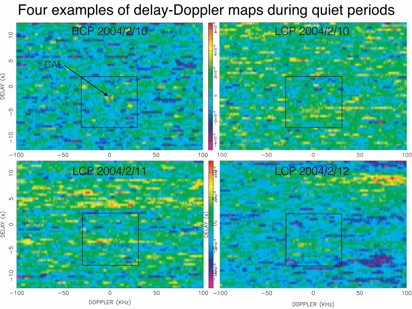
RCP 2004/2/10 LCP 2004/2/10
CAL
LCP 2004/2/11 LCP 2004/2/12
Four examples of delay-Doppler maps during quiet periods
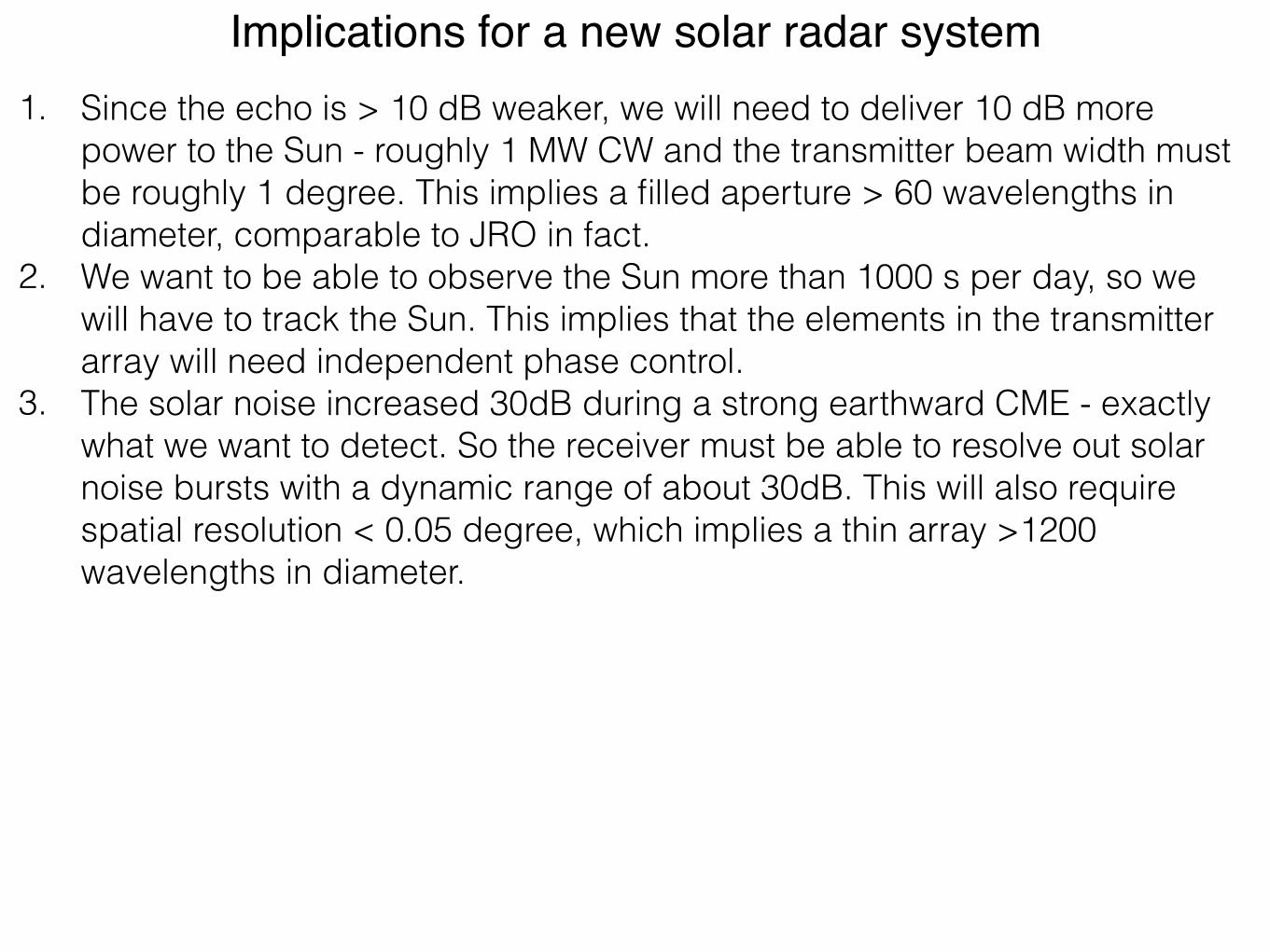
1. Since the echo is > 10 dB weaker, we will need to deliver 10 dB more power to the Sun - roughly 1 MW CW and the transmitter beam width must be roughly 1 degree. This implies a filled aperture > 60 wavelengths in diameter, comparable to JRO in fact.
2. We want to be able to observe the Sun more than 1000 s per day, so we will have to track the Sun. This implies that the elements in the transmitter array will need independent phase control.
3. The solar noise increased 30dB during a strong earthward CME - exactly what we want to detect. So the receiver must be able to resolve out solar noise bursts with a dynamic range of about 30dB. This will also require spatial resolution < 0.05 degree, which implies a thin array >1200 wavelengths in diameter.
Implications for a new solar radar system

Transmitter Design• It is almost certainly cost-effective to use an array and very likely cost-effective to put a
power amplifier on each linear element of the array. • The size of the array must be 60 λ in diameter so the number of elements Ne depends on
the element spacing. • The element spacing (in λ) depends on the scan angle, so the spacing may have to be λ/
2 E-W, but might be relaxed somewhat N-S. So Ne ≲ 11300. • Regular spacing is probably most efficient as we would then transmit equal power from
each element. A hexagonal arrangement is likely preferred. • More elements increases the cost, but decreases the power requirement for each power
amplifier, so the cost is < linear with the number of elements. • Small power amplifiers can be made broad band (28 to 53 MHz?), and flexibility in
transmitting frequency would be very useful for known applications. It would also, perhaps, permit unforeseen applications.
• It is probably efficient to put an intelligent transmitter controller on each element, which would require only a clock signal and a digital link, perhaps ethernet or even WiFi, to be distributed to each element.
• With independent control of each element we could transmit multiple beams in different directions with different power levels, different codes, and even different frequencies, provided only that the total transmitted power/element is respected.
• It would be valuable to be able to receive with the same antenna. With distributed power amplification the T/R switch should be relatively simple to design. In addition to receiving and analyzing an echo for scientific purposes, the echo can also be used for calibration of the array.

Other considerations
• Transmitter (cont) • CW Broadband, able to work on pulsed mode. • Linear, circular, elliptical polarizations. • Broadband antenna element for transmission. Modified LOFAR LB or LWA?
• Array calibration • Radio sources (e.g., Cygnus A, Cassiopeia, Hydra) • Use of drones (reflectors or radio beacons).

ImprovedMLTwindmeasurements:
MMARIAapproach(Multi-static,Multi-FrequencyMeteorRadar)
J.Chau,G.Stober,J.Vierinen,etal.
[see Stober and Chau, RS, 2015, Vierinen et al., 2016]

Windfield:First-orderTaylorexpansion

MMARIA:Multi-static,Multi-frequency,Multi-transmitter
Northern Norway Northern Germany
Andenes,Trømso,Kiruna, Sodankyla,Trondheim, Alta, Svalbard
Juliusruh, Collm, Kborn

MMARIAApproach:Advantages
Improvement Relevance
(1)Increasednumberofdetections
Bettertimeandaltituderesolution
(2)ObservationoflargereffectiveBraggwavelengths
Higheraltitudecoverage
(3)Multipleobservinganglesofcommonvolume
Extractionofparameterslikerelativevorticity,horizontaldivergence,shear,stretching,…
(1)and(3) ImprovedeterminationofGWparametersinbothtimeandspace(3D)

-200
-100
0
100
200 1.00UT
4.00UT
7.00UT
10.00UT
-200 -100 0 100 200EW (km)
-200
-100
0
100
200 13.00UT
-200 -100 0 100 200EW (km)
16.00UT
-200 -100 0 100 200EW (km)
19.00UT
-200 -100 0 100 200EW (km)
22.00UT
From: 14-Mar-2016, to: 20-Mar-2016
ExamplefromsimultaneousPulsedandSpread-spectrumCampaign
-200
-100
0
100
200 1.00UT
4.00UT
7.00UT
10.00UT
-200 -100 0 100 200EW (km)
-200
-100
0
100
200 13.00UT
-200 -100 0 100 200EW (km)
16.00UT
-200 -100 0 100 200EW (km)
19.00UT
-200 -100 0 100 200EW (km)
22.00UT
From: 14-Mar-2016, to: 20-Mar-2016
Only P
ulsed-Link A
ll bistatic links
Rx 2
Pulsed + Rx1
CW1 CW2
Four links: • Pulsed – Rx1 • Pulsed – Rx2 • CW1 – Rx2 • CW2 – Rx2 Transmission in the same frequency! Only 400 W CW Power on each CW link (compared to 1.2 kW avg – Pulsed).

ExamplefromAndenes-Tromso
Climatology
8284868890929496
(km
)
U (VVP)
m/s
-30.00
-15.00
0.00
15.00
30.00
8284868890929496
(km
)
V (VVP)
m/s
-30.00
-15.00
0.00
15.00
30.00
8284868890929496
(km
)
Hor . div
m/s
/km
-0.10
-0.05
0.00
0.05
0.10
8284868890929496
(km
)Rel. Vor t .
m/s
/km
-0.10
-0.05
0.00
0.05
0.10
D J F M A M J J A S O N D Day of the year
8284868890929496
(km
)
w, wtop = 0.000
m/s
-0.40
-0.20
0.00
0.20
0.40
2004-2005-2006-2007-2008-2009-2010-2011-2012-2013-2014-2015
Composite over Andenes-Tromso (69.4N)
-200 -100 0 100 200EW (km)
-200
-100
0
100
200
NS
(km
)
a ndenes,t romso, 12.00UT
From: 20-J un-2015, to: 29-J un-2015
-200
-100
0
100
200 1.00UT
4.00UT
7.00UT
10.00UT
-200 -100 0 100 200EW (km)
-200
-100
0
100
200 13.00UT
-200 -100 0 100 200EW (km)
16.00UT
-200 -100 0 100 200EW (km)
19.00UT
-200 -100 0 100 200EW (km)
22.00UT
From: 20-J un-2015, to: 29-J un-2015

MMARIAandSolarRadar/Radio Asolarradarwouldbeasuperb“all-in-one”meteorradar: Head-echoes:Meteormass,Meteorpopulations,etc. Non-specular:Higheraltitudewinds,plasmaphysics
Specularechoes:MMARIAwindfieldswithin300-700kmradius(forallpracticalpurposes,asolarradarwouldbean“all-sky”illuminator).
TechnicalRequirements: Multi-staticcapabilities
“Knowledge”oftransmittingsequence.
• Solar VHF receivers are excellent for MMARIA applications, either receiving solar radar signals or receiving other existing transmitters (FM, TV, existing meteor radars, etc.).
• Technical Requirement: Access to few (5-7) closely spaced antennas in parallel to any solar/astronomical application. We are currently evaluating such possibility with LOFAR.

Personal“opinions”onwhattoconsider TheUSspacesciencecommunityneedsabettercoordination(orintegration)betweenNSFGeospaceandNSFAstronomyonsolar-relatedresearch.Similarly,abettercoordinationbetweenNASAandNSFGeospace(e.g.,wouldGeospacecubesatsbeagoodideaforanNSF-MREFC?)
ThenextGeospaceNSF-MREFC? DASI-like“small/large”instrumentsorsingleLargefacility(andclustered
instrumentation)? DASIisnotjustaboutresources,nationalandinternationalcollaborationiscrucial.
Transformationalscienceand/orService? Afacilitywithasignificantbettercapability,oranetworkof“standard”instrumentswith24/7capabilities(analogywithOcean,ashiporbuoys?).
Towardsresearchortowardsoperations.
OneGiantfacilityoraGiantUmbrellaofsmallersystems?


Additionalmaterial

Ionosphere Forcing
[adapted from Marchavilas, 2007]
Ionosphere
Solar/Magnetospheric forcing, e.g.,
geomagnetic storms
Tropospheric/Stratospheric forcing, e.g., planetary
waves, tides, GWs
Ionosphere Lower
atmosphere
Sun Earth Magnetosphere
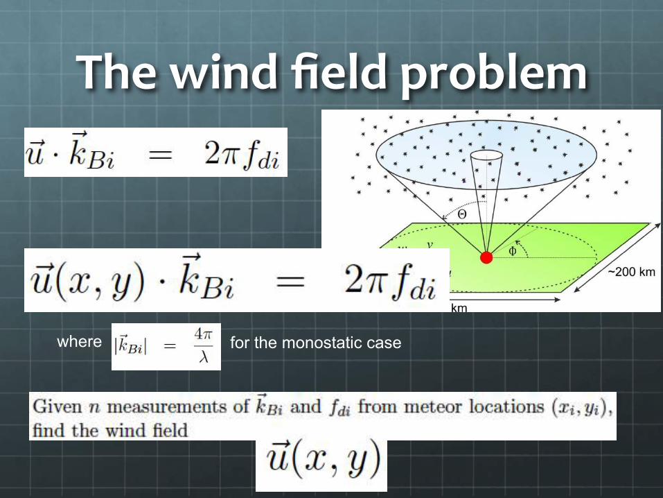
Thewindfieldproblem
where for the monostatic case

Mesosphericwindsandshears
Meteor winds from 3 days
0 50 100 150 200Velocity (m/s)
80
85
90
95
100
Alt
itud
e (k
m)
[from Larsen, 2002]

ExamplefromAndenes-TrømsoSelectedClimatologicalProfiles
U (VVP)
84
86
88
90
92
94
Hei
ght (
km)
V (VVP)
Hor . div
Rel. Vor t .
w, wtop = 0.000
84
86
88
90
92
94
DO
Y:
160
84
86
88
90
92
94
Hei
ght (
km)
84
86
88
90
92
94
DO
Y:
185
84
86
88
90
92
94
Hei
ght (
km)
84
86
88
90
92
94
DO
Y:
210
-30 -20 -10 0 10 20 30m/s
84
86
88
90
92
94
Hei
ght (
km)
-30 -20 -10 0 10 20 30m/s
-0.10 -0.05 0.00 0.05 0.10m/s/km
-0.10 -0.05 0.00 0.05 0.10m/s/km
-0.4 -0.2 0.0 0.2 0.4m/s
84
86
88
90
92
94
DO
Y:
235
2004-2005-2006-2007-2008-2009-2010-2011-2012-2013-2014-2015
Tempora l cu ts over Andenes-Tromso (69.4N)