solar water heater - eco-smart.org · 4.2 work force ... case material 23-gauge aluminium cover...
TRANSCRIPT

SOLAR WATER HEATER

USA INSTALLATION MANUAL 2
TABLE OF CONTENTS
1 0 INTRODUCTION ...........................................................................................................4 1.1 Use of Manual......................................................................................................................... 4 1.2 General Description............................................................................................................. 4 1.3 Specifications of Solahart 300 Series Systems ...................................................................... 5 1.4 System Parts Identification List .................................................................................................. 6 1.5 Solahart Model Details ............................................................................................................... 8
2.0 PRE-INSTALLATION INSPECTION..............................................................................9 2.1 Site Inspection Equipment ...................................................................................................... 9 2.2 Review Local Codes ............................................................................................................... 9 2.3 Choose Solahart Location .................................................................................................... 10
2.3.1 Placement Requirements.............................................................................................................. 10 2.3.2 Area Requirements (refer to Figure 2.3):...................................................................................... 11 2.3.3 Pitch Requirements....................................................................................................................... 12
2.4 Roof Survey .......................................................................................................................... 13 2.5 Roof Support Requirements ................................................................................................. 14
2.5.1 Conventional Roof Modifications .................................................................................................. 14 2.5.2 Truss Frame Modifications............................................................................................................ 15
2.6 General Plumbing Requirements.......................................................................................... 16 2.6.1 Water Quality ................................................................................................................................ 16 2.6.2 Water Pressure ............................................................................................................................. 16 2.6.3 Water Hammer.............................................................................................................................. 16 2.6.4 External Piping Insulation ............................................................................................................. 16
2.7 Plumbing Survey................................................................................................................... 17 2.8 Electrical Survey ................................................................................................................... 21
2.8.1 General Electrical Requirements .................................................................................................. 21 2.9 Customer Approval ............................................................................................................... 22
3.0 HAZARDS AND SAFETY PRECAUTIONS .................................................................23 4.0 PRE-INSTALLATION ..................................................................................................25
4.1 Permits.................................................................................................................................. 25 4.2 Work Force ........................................................................................................................... 25 4.3 Inventory ............................................................................................................................... 25 4.4 Required Tools, Equipment and Supplies ............................................................................ 25
5.0 INSTALLATION PROCEDURES.................................................................................26 5.1 Prepare the Roof .................................................................................................................. 26
5.1.1 Roof Reinforcement (if necessary) ............................................................................................... 26 5.1.2 Fragile/Ornamental Roof Material................................................................................................. 26
5.2 Supporting Structure installation........................................................................................... 27 5.2.1 Standard Installation ..................................................................................................................... 27 5.2.2 Metal / Sturdy Tile Installation....................................................................................................... 28 5.2.3 Frame Installation.......................................................................................................................... 30
5.3 Collector Installation ............................................................................................................. 32 5.3.1 Standard Installation ..................................................................................................................... 33 5.3.2 Frame Installation.......................................................................................................................... 34
5.4 Storage Tank Installation ...................................................................................................... 34 5.4.1 Standard Installation ..................................................................................................................... 35 5.4.2 Frame Installation.......................................................................................................................... 36
5.5 Plumbing Installation............................................................................................................. 38 5.6 Electrical Installation ............................................................................................................. 39 5.7 Install Roof - Jack Panel ....................................................................................................... 39 5.8 Connect Plumbing to Storage Tank (refer to Figure 5.13) .................................................... 39 5.9 Fill and Test Potable Water Storage Tank (All Models)........................................................ 40 5.10 Test and Fill the Closed Circuit.......................................................................................... 40
5.10.1 Closed Circuit Fluid (Models J, KF, BCXII & Free Heat ONLY) ................................................... 40 5.10.2 Test and Fill Procedure................................................................................................................. 41
5.11 Closed Circuit Servicing Kit ............................................................................................... 45 5.12 Connect Storage Tank to Electrical Supply ....................................................................... 46 5.13 Complete Solahart Installation........................................................................................... 46
6.0 TROUBLESHOOTING ................................................................................................47 7.0 MAINTENANCE ..........................................................................................................49
USA INSTALLATION MANUAL 3
7.1 Periodic Maintenance ........................................................................................................... 49 7.1.1 Quarterly ....................................................................................................................................... 49 7.1.2 Annually ........................................................................................................................................ 49 7.1.3 Every 3 to 5 Years (10 to 12 years for Free Heat, BCXII and JXII systems)................................ 49
7.2 Maintenance Procedures...................................................................................................... 50 7.2.1 Draining Storage Tank .................................................................................................................. 50 7.2.2 Filling Storage Tank ...................................................................................................................... 51 7.2.3 Drain Closed Circuit ...................................................................................................................... 51 7.2.4 Thermostat Replacement.............................................................................................................. 51 7.2.5 Backup Heating Element Replacement ........................................................................................ 52 7.2.6 Anode Replacement ..................................................................................................................... 53 7.2.7 Pressure-Temperature Relief (P/T) Valve Replacement .............................................................. 54 7.2.8 Collector Replacement.................................................................................................................. 54 7.2.9 Storage Tank Replacement .......................................................................................................... 55
APPENDIX A FRAMES ..................................................................................................57 APPENDIX B THIRD-PANEL PARTS LIST ....................................................................61

USA INSTALLATION MANUAL 4
1 0 INTRODUCTION 1.1 Use of Manual
This manual provides the manufacturers recommended procedures for Solahart Thermosiphon Series solar water-heating systems. The procedures are essential for correct installation, troubleshooting and maintenance.
Read each section of this manual thoroughly before beginning work on the system.
CAUTION
CHANGES TO THE DESIGN OR INTENDED USE OF THE SOLAHART SYSTEM WILL VOID THE MANUFACTURERS WARRANTY.
INSTALLATION, TROUBLESHOOTING, AND MAINTENANCE MUST BE PERFORMED BY A QUALIFIED TECHNICIAN.
1.2 General Description
The solar energy system described by this manual, when properly installed and maintained, meets the minimum standards established by the SRCC. This certification does not imply endorsement or warranty of this product by the SRCC.
The Solahart J, KF, BCXII and Free Heat systems operate on the passive thermosiphon principle and are revolutionary in their use of a ‘closed circuit’ to provide fail-safe freeze protection of the collector closed circuit. The closed circuit consists of the solar absorbers, a single wall heat exchanger around the outside of the storage tank, and plumbing attachments.
Radiant energy from the sun heats the special long-life fluid in the solar collectors. As the fluid is heated, it rises into the tank heat exchanger and heats the potable water stored within.
The hot potable water is stored in a well-insulated steel storage tank, which is lined with two coats of Primaglaze vitreous enamel for high temperature stability.
Flow of the closed circuit fluid, using the passive thermosiphon principle, is accomplished without pumps, sensors or moving parts.
Solahart L model systems also operate using the passive thermosiphon principle, without a closed circuit system. Instead, potable water is circulated directly from the solar collectors into the storage tank, Solahart L model systems are not suitable for locations that are prone to freeze conditions or where the air temperature
can fall below 41°F.
NOTE
FREEZE TOLERANCE LIMITS ARE BASED UPON AN ASSUMED SET OF ENVIRONMENTAL CONDITIONS.
Figure 1.1 Illustration of Typical System

USA INSTALLATION MANUAL 5
1.3 Specifications of Solahart 300 Series Systems
STORAGE CYLINDER
Total Capacity (Nominal) 80 Gallons
Overall Size (L x W x H) 90” x 20” x 20"
Nominal Working Pressure 15 - 145 psi
Weight Empty 226 lbs.
Weight Installed 874 lbs.
Immersion Element (Booster) 2.4 kW 220/240 V
Nominal Temperature Setting 120 - 140°F
Cylinder Material 12 gauge low-carbon steel
Cylinder Lining 2 coats specially developed “Primaglaze”
High temperature vitreous enamel
Insulation Pressure injected Polyurethane foam
Test Pressure 300 psi
COLLECTORS (2)*
Overall Size (W x L) 82” x 76"
Nominal Area 43 sq. ft.
Case Material 23-gauge aluminium
Cover Material Low iron tempered glass
Insulation material Grey Polyester (KF uses FSB1 Fibre Glass)
Absorber Material 23 gauge low-carbon steel
Weight Empty 2 x 84 lbs.
Weight Installed 2 x 96 lbs.
Plate-to-Plate Bonding Electric Welding
Test Pressure 43 – 65 psi
Nominal Working Pressure - 0.2 to 11.5 psi
*Optional additional third collector available
USA INSTALLATION MANUAL 6
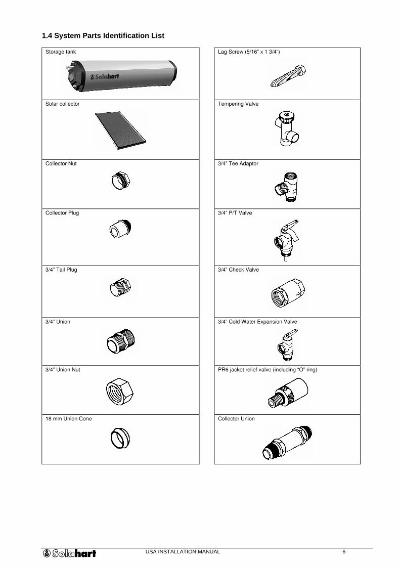
1.4 System Parts Identification List
Storage tank
Lag Screw (5/16” x 1 3/4”)
Solar collector
Tempering Valve
Collector Nut
3/4” Tee Adaptor
Collector Plug
3/4” P/T Valve
3/4” Tail Plug
3/4” Check Valve
3/4” Union
3/4” Cold Water Expansion Valve
3/4” Union Nut
PR6 jacket relief valve (including “O” ring)
18 mm Union Cone
Collector Union
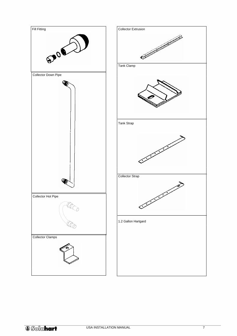
USA INSTALLATION MANUAL 7
Collector Down Pipe
Fill Fitting
Collector Extrusion
Tank Clamp
Tank Strap
Collector Strap
1.2 Gallon Hartgard
Collector Hot Pipe
Collector Clamps
USA INSTALLATION MANUAL 8
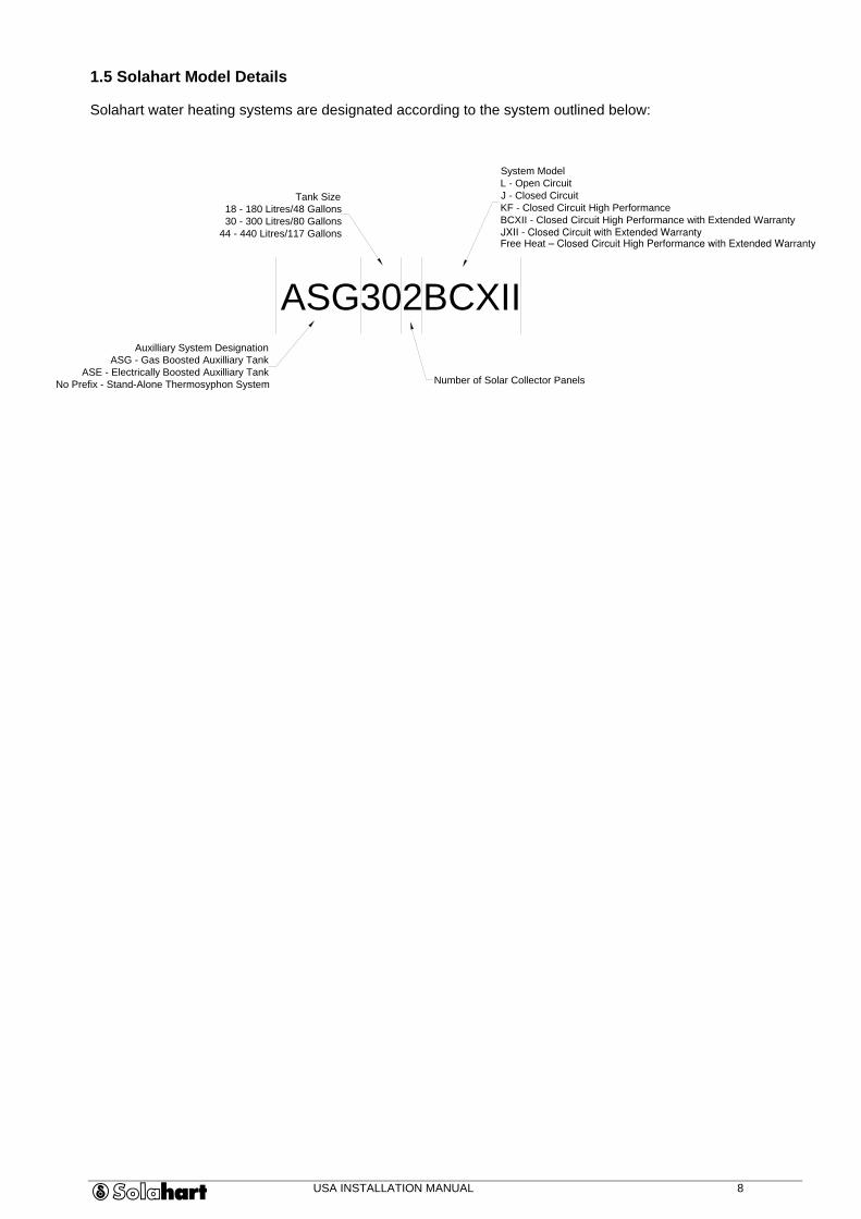
1.5 Solahart Model Details
Solahart water heating systems are designated according to the system outlined below:
ASG302BCXII
Auxilliary System Designation ASG - Gas Boosted Auxilliary Tank
ASE - Electrically Boosted Auxilliary Tank No Prefix - Stand-Alone Thermosyphon System
Tank Size 18 - 180 Litres/48 Gallons 30 - 300 Litres/80 Gallons
44 - 440 Litres/117 Gallons
Number of Solar Collector Panels
System Model L - Open Circuit J - Closed Circuit KF - Closed Circuit High Performance BCXII - Closed Circuit High Performance with Extended Warranty Free Heat – Closed Circuit High Performance with Extended Warranty JXII - Closed Circuit with Extended Warranty
USA INSTALLATION MANUAL 9
2.0 PRE-INSTALLATION INSPECTION
This section will guide you to gather the necessary information to install the system correctly. Use it together with the Pre-Installation Checklist (supplied by local Solahart dealer) to identify all installation requirements.
The pre-installation inspection procedures include;
• Review of local building codes for site requirements and specific guidelines for plumbing and electrical installation,
• Inspection of installation site,
• Completion of the Pre-installation Checklist, including customer’s signature.
2.1 Site Inspection Equipment
• Pre-Installation Inspection Checklist
• Pencil or pen
• Ladder
• Tape measure
• Flashlight
• Water pressure gauge
• Pitch gauge
• Compass
2.2 Review Local Codes
2.2.1 Review local codes and record on checklist:
• Area requirements
• Plumbing requirements
• Electrical requirements
• Roof support stress load and modification requirements (including engineering review, if necessary).
2.2.2 Obtain building plans, if possible, to help locate bearing walls and determine truss strength.
2.2.3 Record extreme weather conditions on checklist;
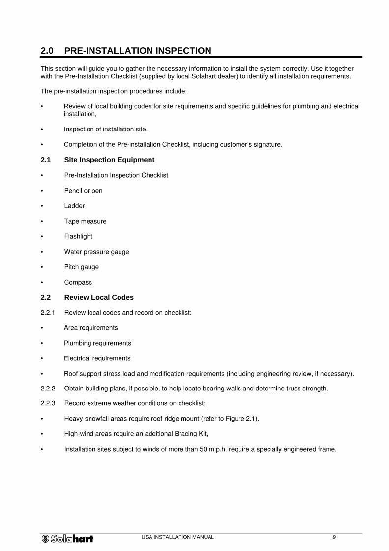
• Heavy-snowfall areas require roof-ridge mount (refer to Figure 2.1),
• High-wind areas require an additional Bracing Kit,
• Installation sites subject to winds of more than 50 m.p.h. require a specially engineered frame.
USA INSTALLATION MANUAL 10
Figure 2.1 Roof-Ridge Mounts
2.3 Choose Solahart Location
2.3.1 Placement Requirements
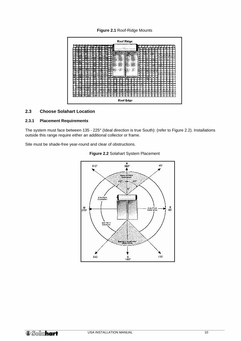
The system must face between 135 - 225° (Ideal direction is true South): (refer to Figure 2.2). Installations outside this range require either an additional collector or frame.
Site must be shade-free year-round and clear of obstructions.
Figure 2.2 Solahart System Placement
USA INSTALLATION MANUAL 11
2.3.2 Area Requirements (refer to Figure 2.3):
No. of Collectors Installation Area Required
2 8’x 8’
3 8' x 12’
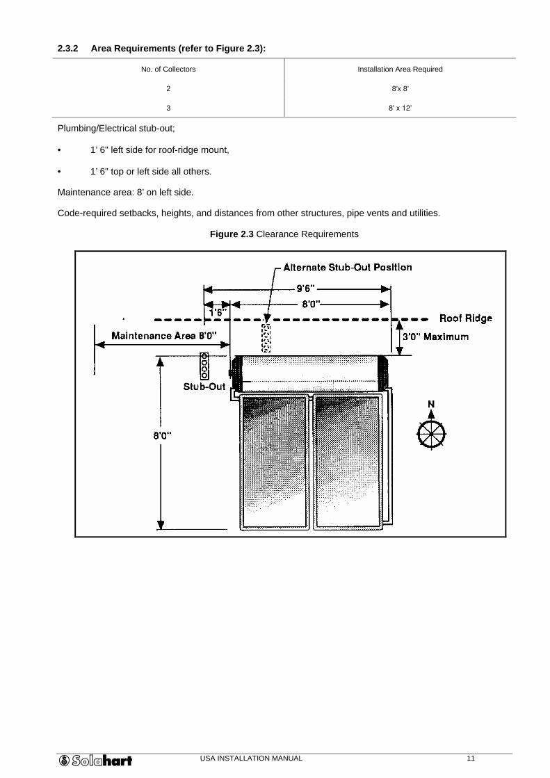
Plumbing/Electrical stub-out;
• 1’ 6" left side for roof-ridge mount,
• 1’ 6" top or left side all others.
Maintenance area: 8’ on left side.
Code-required setbacks, heights, and distances from other structures, pipe vents and utilities.
Figure 2.3 Clearance Requirements

USA INSTALLATION MANUAL 12
2.3.3 Pitch Requirements
Correct operation requires a 15°- 45° pitch (slope). This can be done by using the roof slope itself or a frame (refer to Figure 2.4).
Figure 2.4 Frame Installations
CAUTION
DO NOT INSTALL ON ROOF WITH PITCH BEYOND 45q.
Use pitch gauge and compass and complete the following steps. Record the results on the checklist.
• Record pitch and compass bearing of proposed installation site.
• Using Table 2.1, select number of collectors and correct installation type.
USA INSTALLATION MANUAL 13
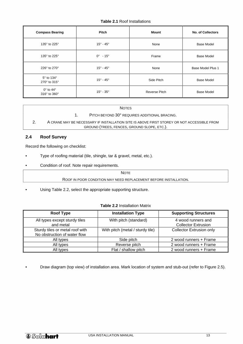
Table 2.1 Roof Installations
Compass Bearing Pitch Mount No. of Collectors
135° to 225° 15° - 45° None Base Model
135° to 225° 0° - 15° Frame Base Model
226° to 270° 15° - 45° None Base Model Plus 1
5° to 134° 270° to 315° 15° - 45° Side Pitch Base Model
0° to 44° 316° to 360° 15° - 35° Reverse Pitch Base Model
NOTES
1. PITCH BEYOND 30° REQUIRES ADDITIONAL BRACING.
2. A CRANE MAY BE NECESSARY IF INSTALLATION SITE IS ABOVE FIRST STOREY OR NOT ACCESSIBLE FROM GROUND (TREES, FENCES, GROUND SLOPE, ETC.).
2.4 Roof Survey
Record the following on checklist:
• Type of roofing material (tile, shingle, tar & gravel, metal, etc.).
• Condition of roof. Note repair requirements.
NOTE
ROOF IN POOR CONDITION MAY NEED REPLACEMENT BEFORE INSTALLATION.
• Using Table 2.2, select the appropriate supporting structure.
Table 2.2 Installation Matrix
Roof Type Installation Type Supporting Structures
All types except sturdy tiles and metal
With pitch (standard) 4 wood runners and Collector Extrusion
Sturdy tiles or metal roof with No obstruction of water flow
With pitch (metal / sturdy tile) Collector Extrusion only
All types Side pitch 2 wood runners + Frame All types Reverse pitch 2 wood runners + Frame All types Flat / shallow pitch 2 wood runners + Frame
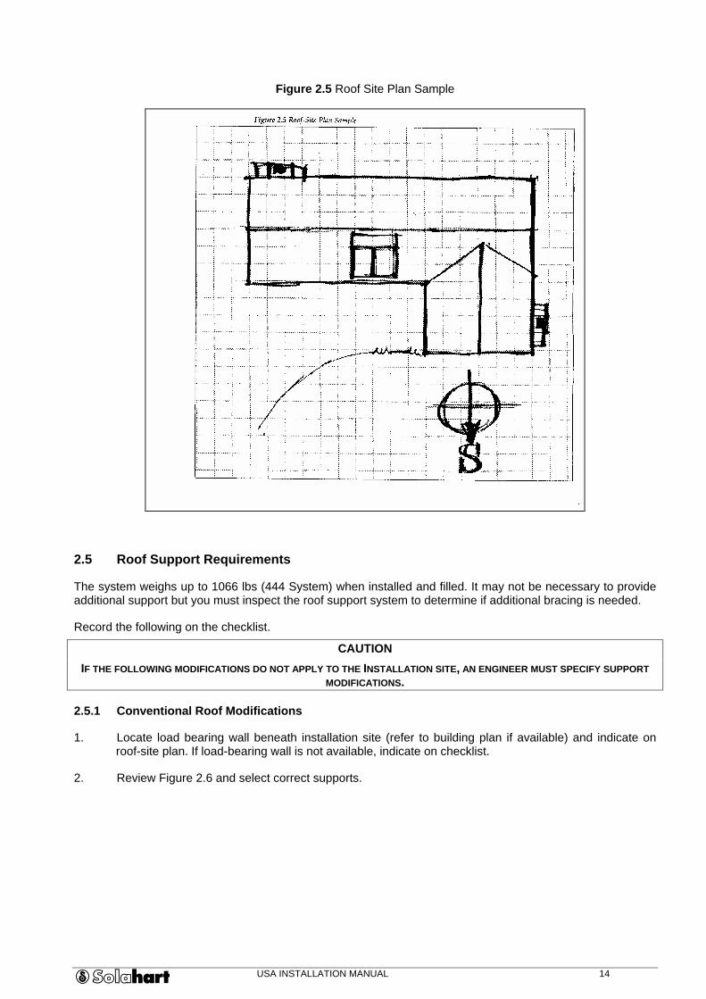
• Draw diagram (top view) of installation area. Mark location of system and stub-out (refer to Figure 2.5).
USA INSTALLATION MANUAL 14
Figure 2.5 Roof Site Plan Sample
2.5 Roof Support Requirements
The system weighs up to 1066 lbs (444 System) when installed and filled. It may not be necessary to provide additional support but you must inspect the roof support system to determine if additional bracing is needed.
Record the following on the checklist.
CAUTION
IF THE FOLLOWING MODIFICATIONS DO NOT APPLY TO THE INSTALLATION SITE, AN ENGINEER MUST SPECIFY SUPPORT MODIFICATIONS.
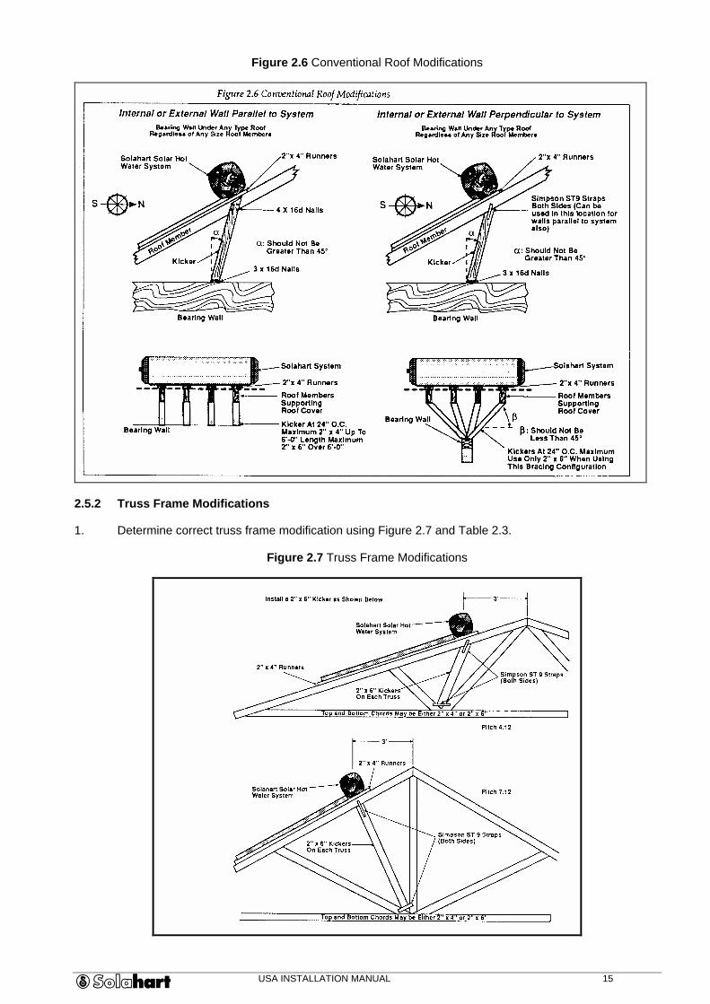
2.5.1 Conventional Roof Modifications
1. Locate load bearing wall beneath installation site (refer to building plan if available) and indicate on roof-site plan. If load-bearing wall is not available, indicate on checklist.
2. Review Figure 2.6 and select correct supports.
USA INSTALLATION MANUAL 15
Figure 2.6 Conventional Roof Modifications
2.5.2 Truss Frame Modifications
1. Determine correct truss frame modification using Figure 2.7 and Table 2.3.
Figure 2.7 Truss Frame Modifications
USA INSTALLATION MANUAL 16
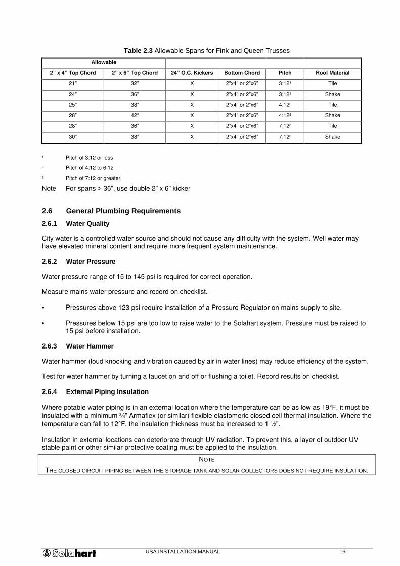
Table 2.3 Allowable Spans for Fink and Queen Trusses
Allowable
2” x 4” Top Chord 2” x 6” Top Chord 24” O.C. Kickers Bottom Chord Pitch Roof Material
21” 32” X 2”x4” or 2”x6” 3:12¹ Tile
24” 36” X 2”x4” or 2”x6” 3:12¹ Shake
25” 38” X 2”x4” or 2”x6” 4:12² Tile
28” 42“ X 2”x4” or 2”x6” 4:12² Shake
28” 36” X 2”x4” or 2”x6” 7:12³ Tile
30” 38” X 2”x4” or 2”x6” 7:12³ Shake
¹ Pitch of 3:12 or less
² Pitch of 4:12 to 6:12
³ Pitch of 7:12 or greater
Note For spans > 36”, use double 2” x 6” kicker
2.6 General Plumbing Requirements
2.6.1 Water Quality
City water is a controlled water source and should not cause any difficulty with the system. Well water may have elevated mineral content and require more frequent system maintenance.
2.6.2 Water Pressure
Water pressure range of 15 to 145 psi is required for correct operation.
Measure mains water pressure and record on checklist.
• Pressures above 123 psi require installation of a Pressure Regulator on mains supply to site.
• Pressures below 15 psi are too low to raise water to the Solahart system. Pressure must be raised to 15 psi before installation.
2.6.3 Water Hammer
Water hammer (loud knocking and vibration caused by air in water lines) may reduce efficiency of the system.
Test for water hammer by turning a faucet on and off or flushing a toilet. Record results on checklist.
2.6.4 External Piping Insulation
Where potable water piping is in an external location where the temperature can be as low as 19°F, it must be
insulated with a minimum ¾” Armaflex (or similar) flexible elastomeric closed cell thermal insulation. Where the
temperature can fall to 12°F, the insulation thickness must be increased to 1 ½”.
Insulation in external locations can deteriorate through UV radiation. To prevent this, a layer of outdoor UV stable paint or other similar protective coating must be applied to the insulation.
NOTE
THE CLOSED CIRCUIT PIPING BETWEEN THE STORAGE TANK AND SOLAR COLLECTORS DOES NOT REQUIRE INSULATION.
USA INSTALLATION MANUAL 17
2.7 Plumbing Survey
Choose installation type from the following;
1. As a replacement for an existing water heater, refer to Figure 2.8 (Preferred).
2. As the sole source of hot water for new construction or locations without a previous water heater, refer to Figure 2.9.
3. As a pre-heater to an existing water heater, refer to Figure 2.10.
NOTES
1. USING THE SYSTEM AS PRE-HEATER TO AN ELECTRIC WATER HEATER IS LESS EFFICIENT THAN A STAND-ALONE SYSTEM. (NON-PREFERRED). DO NOT PERFORM THIS INSTALLATION UNLESS SPECIFICALLY REQUESTED BY THE
CUSTOMER.
2. ALL PLUMBING INSTALLATION MUST CONFORM TO LOCAL CODES.
3. ALL PIPING MUST BE ADEQUATELY SUPPORTED; SUPPORTS MUST CONFORM TO LOCAL CODES.
4. ALL PIPING MUST BE ADEQUATELY INSULATED; INSULATION MUST CONFORM TO LOCAL CODES.
4. ALL PIPING MUST BE SLOPED TO DRAIN.
CAUTION
PLUMBING MUST BE INSTALLED SO THAT THE PERFORMANCE OF ANY FIRE-RATED ASSEMBLY IS NOT REDUCED.

USA INSTALLATION MANUAL 18
Figure 2.8 Plumbing Schematic for Replacement of Existing Electric Water Heater (Preferred)
This method is also used for Auxiliary system connections where the electric or gas water heater remains and the solar water heater serves as a pre-heater to it.
Typical for models J, KF, BCXII & Free Heat
Typical for Model L
TWV1
ASE302KF
300 J Tank
KF Collector
Cold Supply
Hot Outlet
PT
Trio
Roof Level
Ground Level
19.7 mm
19.7 mm
System Schematic Model
M = Mixing Valve PT = Pressure & Temperature Relief Valve Trio = Combination Cold Relief Valve , Strainer & Stop Cock
Note: All pipe work ¾ ” BSP unless otherwise stated M
TWV2 Pre Heat
Storage Tank
1 2 2
1
TWV 1 = Two Way Valve 1 - Inlet Selector TWV 2 = Two Way Valve 1 - Outlet Selector Pre Heat = Solar Pre Heat Valve
Drain Lines at Ground Level
Drain Line at Ground Level
Valve Settings; Solar Only = (TWV1 – 1)+(TWV2 – 1)+(Pre Heat OFF) Storage Only = (TWV1 – 2)+(TWV2 - 2)+(Pre Heat OFF) Solar Pre Heat = (TWV1 - 1)+(TWV2 - 2)+(Pre Heat ON)
KF Collector
TWV1
300 J Tank
Cold Supply
Hot Outlet
PT PT
Trio Trio
Roof Level
Ground Level
19.7 mm
19.7 mm
System Schematic Model
M = Mixing Valve PT = Pressure & Temperature Relief Valve Trio = Combination Cold Relief Valve , Strainer & Stop Cock
Note: All pipe work ¾ ” BSP unless otherwise stated M
TWV2
TWV1
ASG302L
300 L Tank
L Collector
Cold Supply
Hot Outlet
PT
Trio
Roof Level
Ground Level
25.4 mm
25.4 mm
System Schematic Model
M = Mixing Valve PT = Pressure & Temperature Relief Valve Trio = Combination Cold Relief Valve , Strainer & Stop Cock
Note: All pipe work ¾ ” BSP unless otherwise stated M
TWV2 Pre Heat
Storage Tank
1 2 2
1
TWV 1 = Two Way Valve 1 - Inlet Selector TWV 2 = Two Way Valve 1 - Outlet Selector Pre Heat = Solar Pre Heat Valve
Drain Lines at Ground Level
Drain Line at Ground Level
Valve Settings; Solar Only = (TWV1 – 1)+(TWV2 – 1)+(Pre Heat OFF) Storage Only = (TWV1 – 2)+(TWV2 - 2)+(Pre Heat OFF) Solar Pre Heat = (TWV1 - 1)+(TWV2 - 2)+(Pre Heat ON)
L Collector
TWV1
300 L Tank
L Collector
Cold Supply
Hot Outlet
PT PT
Trio Trio
Roof Level
Ground Level
25.4 mm
25.4 mm
System Schematic Model
M = Mixing Valve PT = Pressure & Temperature Relief Valve Trio = Combination Cold Relief Valve , Strainer & Stop Cock
Note: All pipe work ¾ ” BSP unless otherwise stated M
TWV2
USA INSTALLATION MANUAL 19
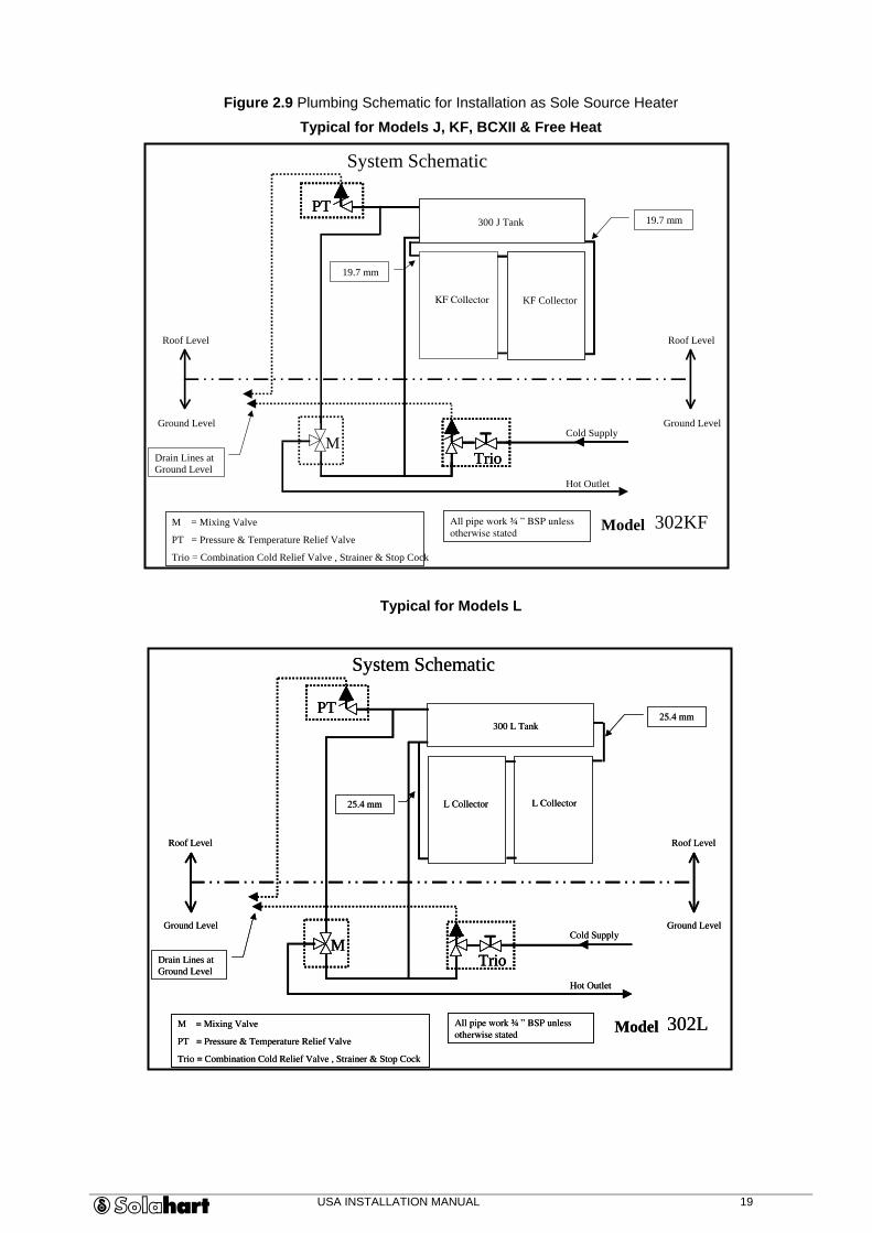
Figure 2.9 Plumbing Schematic for Installation as Sole Source Heater
Typical for Models J, KF, BCXII & Free Heat
Typical for Models L
PT
Trio M
302KF
300 J Tank
KF Collector
Cold Supply
Hot Outlet
Roof Level
Ground Level
Roof Level
Ground Level
Drain Lines at Ground Level
19.7 mm
19.7 mm
System Schematic
Model M = Mixing Valve PT = Pressure & Temperature Relief Valve Trio = Combination Cold Relief Valve , Strainer & Stop Cock
All pipe work ¾ ” BSP unless otherwise stated
KF Collector
PT PT
Trio Trio
PT
TrioM
302L
300 L Tank
L Collector
Cold Supply
Hot Outlet
Roof Level
Ground Level
Roof Level
Ground Level
Drain Lines at Ground Level
25.4 mm
25.4 mm
System Schematic
ModelM = Mixing Valve
PT = Pressure & Temperature Relief Valve
Trio = Combination Cold Relief Valve , Strainer & Stop Cock
All pipe work ¾ ” BSP unless
otherwise stated
L Collector
PTPT
TrioTrioMM
302L
300 L Tank
L Collector
Cold Supply
Hot Outlet
Roof Level
Ground Level
Roof Level
Ground Level
Drain Lines at
Ground Level
25.4 mm
25.4 mm
System Schematic
ModelM = Mixing Valve
PT = Pressure & Temperature Relief Valve
Trio = Combination Cold Relief Valve , Strainer & Stop Cock
All pipe work ¾ ” BSP unless
otherwise stated
L Collector

USA INSTALLATION MANUAL 20
Figure 2.10 Plumbing Schematic for installation as Pre Heater
Typical for Models J, KF, BCXII & Free Heat
Typical for Model L
TWV1
ASE302L
300 L Tank
L Collector
Cold Supply
Hot Outlet
PT
Trio
Roof Level
Ground Level
25.4 mm
25.4 mm
System Schematic Model
M = Mixing Valve PT = Pressure & Temperature Relief Valve Trio = Combination Cold Relief Valve , Strainer & Stop Cock
Note: All pipe work ¾ ” BSP unless otherwise stated M
TWV2 Pre Heat
Storage Tank
1 2 2
1
TWV 1 = Two Way Valve 1 - Inlet Selector TWV 2 = Two Way Valve 1 - Outlet Selector Pre Heat = Solar Pre Heat Valve
Drain Lines at Ground Level
Drain Line at Ground Level
Valve Settings; Solar Only = (TWV1 – 1)+(TWV2 – 1)+(Pre Heat OFF) Storage Only = (TWV1 – 2)+(TWV2 - 2)+(Pre Heat OFF) Solar Pre Heat = (TWV1 - 1)+(TWV2 - 2)+(Pre Heat ON)
L Collector
TWV1
300 L Tank
L Collector
Cold Supply
Hot Outlet
PT PT
Trio Trio
Roof Level
Ground Level
25.4 mm
25.4 mm
System Schematic Model
M = Mixing Valve PT = Pressure & Temperature Relief Valve Trio = Combination Cold Relief Valve , Strainer & Stop Cock
Note: All pipe work ¾ ” BSP unless otherwise stated M
TWV2
TWV1
ASE302KF
300 J Tank
KF Collector
Cold Supply
Hot Outlet
PT
Trio
Roof Level
Ground Level
19.7 mm
19.7 mm
System Schematic Model
M = Mixing Valve PT = Pressure & Temperature Relief Valve Trio = Combination Cold Relief Valve , Strainer & Stop Cock
Note: All pipe work ¾ ” BSP unless otherwise stated M
TWV2 Pre Heat
Storage Tank
1 2 2
1
TWV 1 = Two Way Valve 1 - Inlet Selector TWV 2 = Two Way Valve 1 - Outlet Selector Pre Heat = Solar Pre Heat Valve
Drain Lines at Ground Level
Drain Line at Ground Level
Valve Settings; Solar Only = (TWV1 – 1)+(TWV2 – 1)+(Pre Heat OFF) Storage Only = (TWV1 – 2)+(TWV2 - 2)+(Pre Heat OFF) Solar Pre Heat = (TWV1 - 1)+(TWV2 - 2)+(Pre Heat ON)
KF Collector
TWV1
300 J Tank
Cold Supply
Hot Outlet
PT PT
Trio Trio
Roof Level
Ground Level
19.7 mm
19.7 mm
System Schematic Model
M = Mixing Valve PT = Pressure & Temperature Relief Valve Trio = Combination Cold Relief Valve , Strainer & Stop Cock
Note: All pipe work ¾ ” BSP unless otherwise stated M
TWV2
USA INSTALLATION MANUAL 21
2.8 Electrical Survey
If the system is being used as a pre-heater to an existing water heater, electrical survey and installation may not be required.
2.8.1 General Electrical Requirements
A 220 Volt, 20 Amp electrical breaker is required to activate the Backup Heating Element located near or as part of the main circuit breaker/fuse panel.
The system may be installed with either of the following options;
• Timer for heating element (Solahart recommends installation near the main electrical panel).
• Indoor convenience switch.
In order to complete the Electrical Survey follow the procedure outlined below;
1. Check availability of 220-volt, 20-amp breaker. Record on checklist.
2. If breaker is not available, mark location for a separate breaker.
3. Choose location of optional timer and indoor convenience switch. Record on checklist.
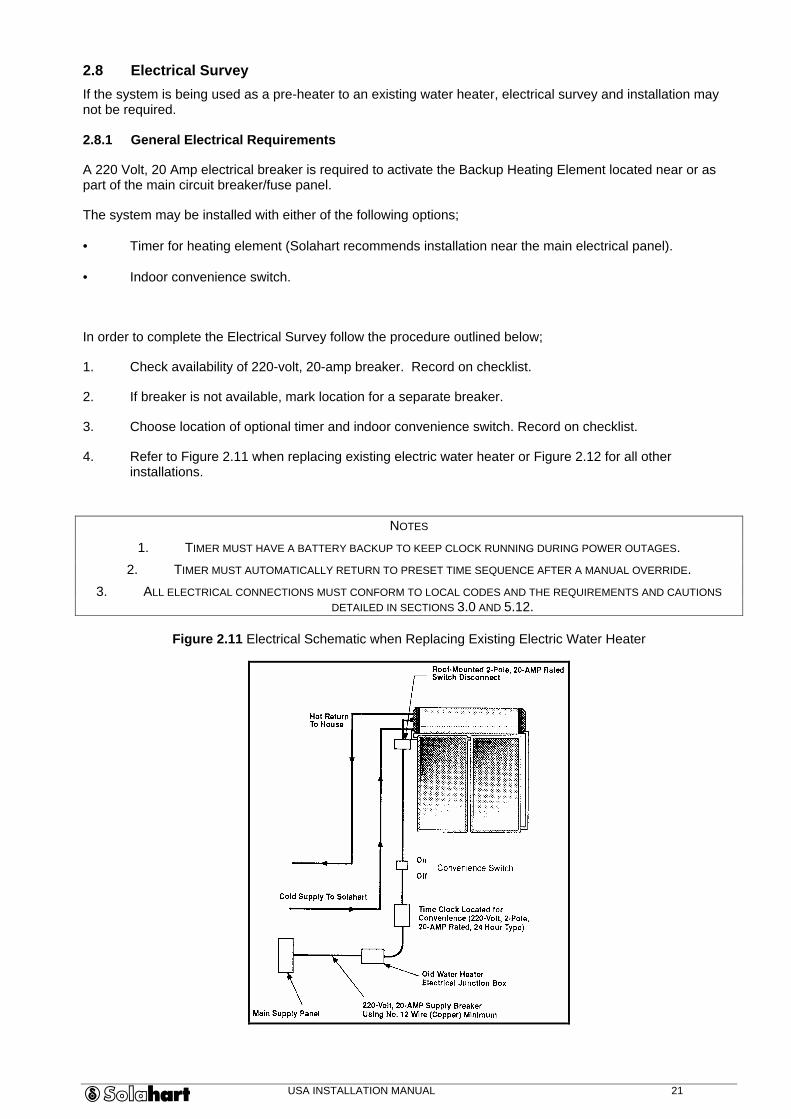
4. Refer to Figure 2.11 when replacing existing electric water heater or Figure 2.12 for all other installations.
NOTES
1. TIMER MUST HAVE A BATTERY BACKUP TO KEEP CLOCK RUNNING DURING POWER OUTAGES.
2. TIMER MUST AUTOMATICALLY RETURN TO PRESET TIME SEQUENCE AFTER A MANUAL OVERRIDE.
3. ALL ELECTRICAL CONNECTIONS MUST CONFORM TO LOCAL CODES AND THE REQUIREMENTS AND CAUTIONS DETAILED IN SECTIONS 3.0 AND 5.12.
Figure 2.11 Electrical Schematic when Replacing Existing Electric Water Heater

USA INSTALLATION MANUAL 22
Figure 2.12 Electrical Schematic for New Installation
2.9 Customer Approval
1. Review checklist with customer and discuss all installation requirements and procedures.
2. Have the customer sign the checklist.

USA INSTALLATION MANUAL 23
3.0 HAZARDS AND SAFETY PRECAUTIONS
IMPORTANT SAFETY INSTRUCTIONS
1. WARNING – When using electrical appliances, basic safety precautions to reduce the risk of fire, electric shock, or injury to persons should be followed, including:
2. READ ALL INSTRUCTIONS BEFORE USING THIS WATER HEATER.
3. The Water Heater must be grounded. Connect only to properly grounded outlet.
4. Install or locate this water heater only in accordance with the provided installation instructions.
5. Use this water heater only for its intended use as described in this manual.
6. Do not use an extension cord set with this water heater. If no receptacle is available adjacent to the water heater, contact a qualified electrician to have one properly installed.
7. As with any appliance, close supervision is necessary when used by children.
8. Do not operate this water heater if it has a damaged cord or plug, if it is not working properly, or if it has been damaged or dropped.
9. This water heater should be serviced only by qualified service personnel. Contact the nearest authorised service facility for examination, repair or adjustment.
SAVE THESE INSTRUCTIONS
For safe installation and operation of the system, review the following hazards and follow all precautions.
HAZARD: Excessive Pressures and Temperatures
PRECAUTION:
To reduce the risk of excessive pressures and temperatures in this water heater, install temperature and pressure protective equipment required by local codes but not less than a combination temperature and pressure relief valve. The valve must be certified by a nationally recognised testing laboratory that maintains periodic inspection of production of listed equipment or materials, as meeting the requirements for Relief Valves and Automatic Gas Shut Off Devices for Hot Water Supply Systems, ANSI Z21.22.
This valve must be marked with a maximum set pressure not to exceed the marked maximum working pressure of the water heater. Install the valve into an opening marked for this purpose in the water heater, and orient it or provide tubing so that any discharge from the valve will exit within 6 inches above, or at any distance below the structural floor, and cannot contact any live electrical part. The discharge opening must not be blocked or reduced in size under any circumstances.
HAZARD: Thermal Expansion
When a water heater is installed in a closed water supply system, such as one having a back-flow preventer in the cold water supply, means shall be provided to control thermal expansion. Contact the water supplier or local plumbing inspector for information regarding the control of this situation.
HAZARD: Electrical Shock
PRECAUTION:
1. Disconnect all power sources before starting installation, maintenance or troubleshooting.
2. Verify mains power is OFF.

USA INSTALLATION MANUAL 24
3. If power is needed later for maintenance, place highly visible tape or tags on all appropriate locations to warn of LIVE electricity.
HAZARD: Burns from Hot Water and Steam
PRECAUTION:
1. Use extreme care when opening relief valves, charging closed circuit, and filling storage tank.
2. The electrical booster thermostat has been factory set at 122ºF (50ºC) to reduce the risk of scald injury. Adjusting the thermostat to a higher setting is not recommended. Hotter water increases the risk of scald injury.
3. Should the thermostat require adjustment to meet the customer demands this can be achieved by rotating the adjustor on the thermostat to the desired temperature.
HAZARD: Burns from Collector Fluid or Downpipe and Hot Pipe
PRECAUTION:
Cover the solar collectors with an opaque (no light can penetrate) material and allow plumbing and fluid to cool before attempting any maintenance.
HAZARD: Heights
PRECAUTIONS:
1. Use extreme care to avoid falling while on a ladder or the roof.
2. If a roof section does not appear to be solid under foot, do not subject it to any added weight until it is adequately reinforced.
USA INSTALLATION MANUAL 25
4.0 PRE-INSTALLATION
Review the checklist for installation requirements. Complete the following before beginning installation.
4.1 Permits
Obtain required permits before installation.
4.2 Work Force
An 80 gall storage tank weighs up to 242lbs empty, requiring a crew of two or more to install.
4.3 Inventory
Review Section 4.4, Frames (Appendix A),Third Panel Parts Kits (Appendix B) and all optional supplies before installation.
4.4 Required Tools, Equipment and Supplies
Basic Plumbing, Electrical and Carpentry Supplies
• Metric wrench (36 mm open end wrench)
• 12” pipe wrench
• Two 12” adjustable (crescent)
• Wrenches
• Water pressure gauge
• Crowbar
• Copper tubing cutter
• Soldering kit
• Caulking gun
• 24” Spirit (bubble) level
• Cable cutter / stripper
• 6” diagonal cutting and long nose pliers
• I00' Grounded extension cord
• Screwdriver Set (# 2 Philip’s, 1/4” Slotted)
• Tape measure (I00 Foot)
• 16-Ounce claw hammer
• Marking pen
• Utility knife
• 3/8”-drive socket set
• 2 Extension ladders
• Flashlight / electric lantern
• Pipe vice / cutter / threader
• Volt, ohm, ammeter
• Hacksaw
• 1/2” Electric drill with bit set
• Skill Saw with standard and masonry blades
• Crane, if required
• 1” Wood-boring bit
Consumable Supplies:
• Masking/duct tape
• Wood/sheet metal screws
• Dielectric pipe unions
• Waterproof sealing compound
• 5/16” Lag Screws, 1 3/4”, 2”, 3”, 6”, as required
• Washers
• Nails, 16g, or assorted, as required
• Silicone sealant
• 2' x 4' x 8'4” redwood or treated-wood
• runners, as required
USA INSTALLATION MANUAL 26
5.0 INSTALLATION PROCEDURES
This section contains instructions for correct installation of the system. Complete the procedures in the order listed.
NOTE
INSTALLATION OF ROOF SUPPORTS, PLUMBING, AND ELECTRICAL MUST CONFORM TO LOCAL CODES.
Installation types are divided into the following:
Standard Installation:
System is mounted to wood runners directly to roof with no need for pitch or directional changes.
Metal / Sturdy Tile Installation:
System is mounted directly to roof with no need for pitch or directional changes.
Frame Installation (Side, Reverse, Shallow-Pitch and Flat-Roof Installation)
System is mounted on frame to provide pitch and/or directional changes.
5.1 Prepare the Roof
5.1.1 Roof Reinforcement (if necessary)
1. Refer to checklist for necessary roof modification.
NOTE
STORAGE TANK WILL BE PARALLEL TO RAFTERS OR TRUSSES FOR SIDE-PITCH MOUNT AND AT A RIGHT ANGLE FOR ALL OTHER MOUNTS.
2. Install supports.
5.1.2 Fragile/Ornamental Roof Material
The system may be installed directly on most roof types if the roof is in good condition with adequate drainage.
For other types of roofs, do the following:
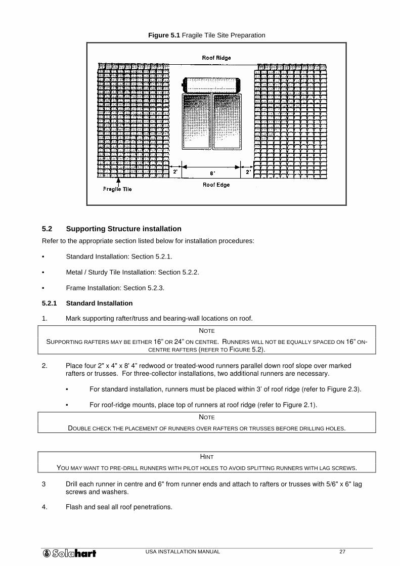
1. Clear area of roofing material from top of roof to lower edge of roof with 2’ clearance on each side (refer to Figure 5.1). Set aside for reinstallation.
2. Install waterproof material over cleared area.
3. Fully seal and waterproof new material.
4. Continue with Section 5.2, Supporting Structure Installation.
USA INSTALLATION MANUAL 27
Figure 5.1 Fragile Tile Site Preparation
5.2 Supporting Structure installation
Refer to the appropriate section listed below for installation procedures:
• Standard Installation: Section 5.2.1.
• Metal / Sturdy Tile Installation: Section 5.2.2.
• Frame Installation: Section 5.2.3.
5.2.1 Standard Installation
1. Mark supporting rafter/truss and bearing-wall locations on roof.
NOTE
SUPPORTING RAFTERS MAY BE EITHER 16” OR 24” ON CENTRE. RUNNERS WILL NOT BE EQUALLY SPACED ON 16” ON-CENTRE RAFTERS (REFER TO FIGURE 5.2).
2. Place four 2" x 4" x 8' 4” redwood or treated-wood runners parallel down roof slope over marked rafters or trusses. For three-collector installations, two additional runners are necessary.
• For standard installation, runners must be placed within 3’ of roof ridge (refer to Figure 2.3).
• For roof-ridge mounts, place top of runners at roof ridge (refer to Figure 2.1).
NOTE
DOUBLE CHECK THE PLACEMENT OF RUNNERS OVER RAFTERS OR TRUSSES BEFORE DRILLING HOLES.
HINT
YOU MAY WANT TO PRE-DRILL RUNNERS WITH PILOT HOLES TO AVOID SPLITTING RUNNERS WITH LAG SCREWS.
3 Drill each runner in centre and 6" from runner ends and attach to rafters or trusses with 5/6" x 6" lag screws and washers.
4. Flash and seal all roof penetrations.

USA INSTALLATION MANUAL 28
Figure 5.2 Wood Runner Installation Detail on 16 " and 24 " On-Center Rafters
5. Position Collector Extrusion so that flat vertical edge is toward roof ridge (refer to Figure 5-3).
Figure 5.3 Collector Extrusion Detail for Standard Installation
CAUTION
EXTRUSION MUST BE HORIZONTAL FOR SYSTEM TO WORK CORRECTLY.
6. Level the Extrusion using a spirit level and shims (refer to Figure 5.3).
7. Mount the Extrusion to each runner using 5/16" x 2” lag screws.
8. Continue with Section 5.3, Collector Installation.
5.2.2 Metal / Sturdy Tile Installation
1. Mark tank location on roof with front foot of tank located directly over reinforced roof area.
2. Measure 82 inches down roof from front foot of tank to determine location for Collector Extrusion.
3. For Tiled rooves, remove tiles to allow for room to screw collector straps to rafters or trusses (refer to Figure 5.4). If installing three collectors, remove tiles for third collector strap.
USA INSTALLATION MANUAL 29
NOTE
BE SURE FLAT SIDE OF VERTICAL SUPPORT OF EXTRUSION FACES TOWARD COLLECTOR LOCATION, AND ’U’ SHAPE OPENS TOWARD LOWER ROOF EDGE.
4. If a third collector is being installed, use a Drive Cleat to attach the Collector Extrusion to the Extrusion Extension (refer to Appendix B).
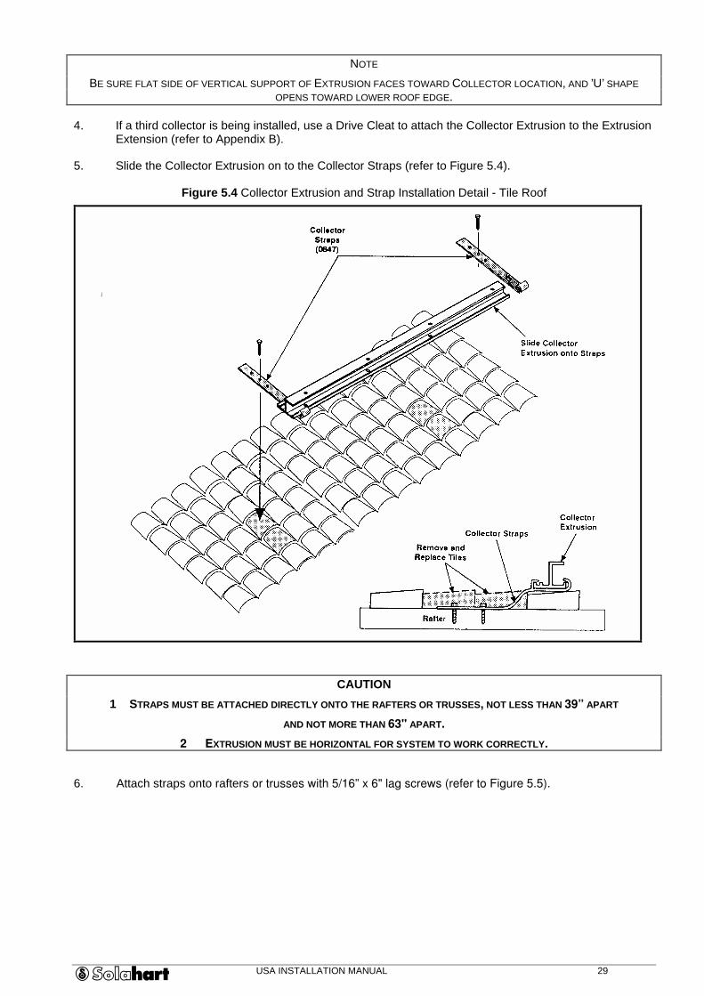
5. Slide the Collector Extrusion on to the Collector Straps (refer to Figure 5.4).
Figure 5.4 Collector Extrusion and Strap Installation Detail - Tile Roof
CAUTION
1 STRAPS MUST BE ATTACHED DIRECTLY ONTO THE RAFTERS OR TRUSSES, NOT LESS THAN 39” APART
AND NOT MORE THAN 63" APART.
2 EXTRUSION MUST BE HORIZONTAL FOR SYSTEM TO WORK CORRECTLY.
6. Attach straps onto rafters or trusses with 5/16” x 6" lag screws (refer to Figure 5.5).

USA INSTALLATION MANUAL 30
Figure 5.5 Collector Extrusion and Strap Installation Detail-Metal Roof
7. Replace tiles that have previously been removed.
NOTE
ENSURE THE WEATHERPROOF SEAL IS RESTORED.
8. Flash and seal all roof penetrations.
9. Continue with Section 5.3, Collector Installation.
5.2.3 Frame Installation
The frame is attached to two wood runners and installed over rafters or trusses, bearing wall or reinforced roof area.
CAUTION
FOR ALL FRAME INSTALLATIONS, TANK-END SUPPORT POINTS MUST BE LOCATED OVER LOAD-BEARING WALL OR A REINFORCED ROOF AREA.
1. Remove roofing if necessary where runners will be installed to provide solid base for the frame.
2. Install two off 2" x 4" x 8'4” redwood or treated-wood runners;
• Mark supporting rafter or truss locations,
• Place tank-end of runners over load-bearing wall,
NOTE
IF RUNNERS BLOCK WATER FLOW, STRADDLE TWO CLOSEST RAFTERS.
• Cut runners to straddle the two closest rafters diagonally,
• Angle runners under support points to permit rainwater drainage,
• Drill each runner in centre and 6" from runner ends and screw to rafters or trusses
with 5/16" x 6" lag screws and washers,
• Flash and seal all roof penetrations.
3. Move all pieces of Frame to roof and assemble (refer to Figure 5.6).

USA INSTALLATION MANUAL 31
Figure 5.6 Frame Assembly
4. Attach Frame to runners:
For shallow-pitch or flat roofs, screw frame directly to runners.
For side pitch or reverse pitch roofs;
• Loosely screw collector end of frame to runners with 5/16" x 1 3/4" lag screws and washers,
• Level frame and measure the required length for the tank-end pipe legs ( 5) (refer to Figure 5.7),
Figure 5.7 Pipe Leg Connection Detail
NOTE
ALLOW ROOM FOR ’U’ BRACKET PIPE-LEG CRADLE ON FRAME.
ROOFS WITH STEEP PITCH (ABOVE 20°) MAY REQUIRE SHORT PIPE LEGS AT COLLECTOR END OF FRAME FOR CLEARANCE
(REFER TO FIGURE 5.7).
• Measure and cut un-drilled end of pipe legs to correct length,
• Attach ’U’ brackets to runners with 5/16" X 1 3/4" lag screws and washers (refer to Figure 5.8),
USA INSTALLATION MANUAL 32
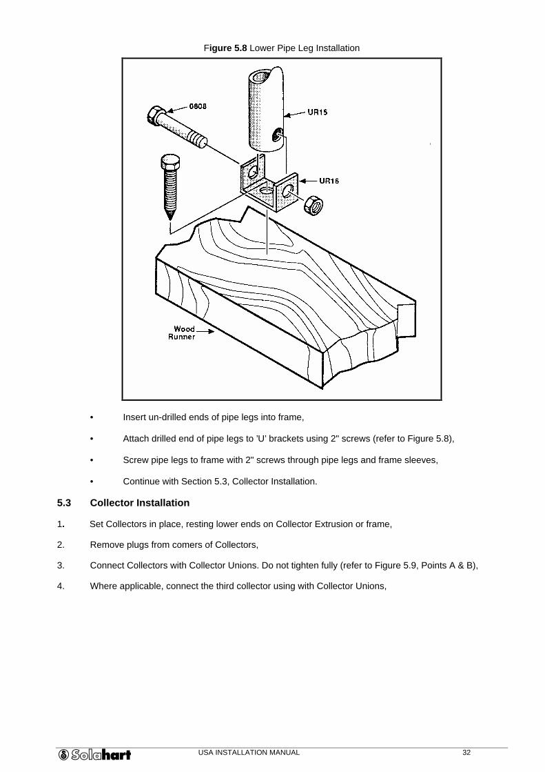
Figure 5.8 Lower Pipe Leg Installation
• Insert un-drilled ends of pipe legs into frame,
• Attach drilled end of pipe legs to ’U’ brackets using 2" screws (refer to Figure 5.8),
• Screw pipe legs to frame with 2" screws through pipe legs and frame sleeves,
• Continue with Section 5.3, Collector Installation.
5.3 Collector Installation
1. Set Collectors in place, resting lower ends on Collector Extrusion or frame,
2. Remove plugs from comers of Collectors,
3. Connect Collectors with Collector Unions. Do not tighten fully (refer to Figure 5.9, Points A & B),
4. Where applicable, connect the third collector using with Collector Unions,
USA INSTALLATION MANUAL 33
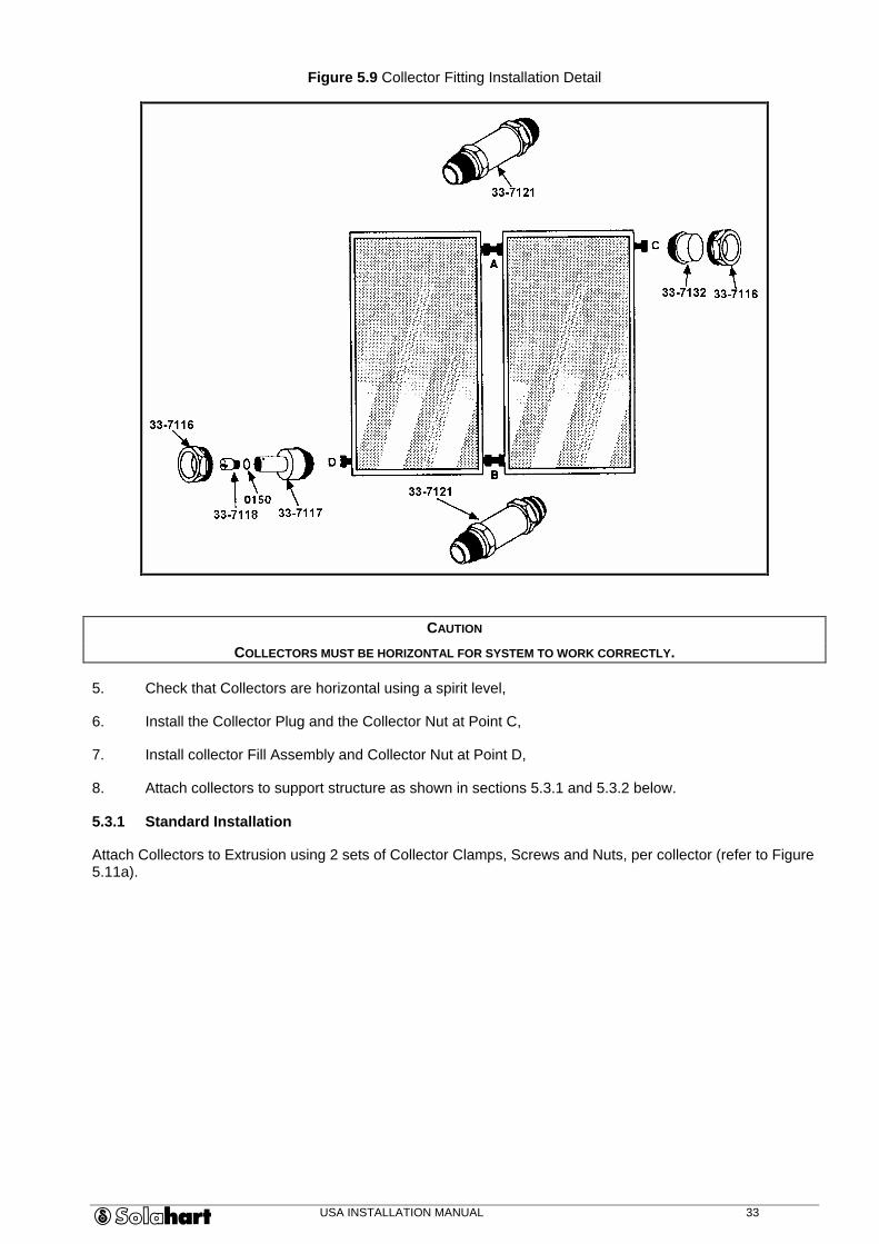
Figure 5.9 Collector Fitting Installation Detail
CAUTION
COLLECTORS MUST BE HORIZONTAL FOR SYSTEM TO WORK CORRECTLY.
5. Check that Collectors are horizontal using a spirit level,
6. Install the Collector Plug and the Collector Nut at Point C,
7. Install collector Fill Assembly and Collector Nut at Point D,
8. Attach collectors to support structure as shown in sections 5.3.1 and 5.3.2 below.
5.3.1 Standard Installation
Attach Collectors to Extrusion using 2 sets of Collector Clamps, Screws and Nuts, per collector (refer to Figure 5.11a).
USA INSTALLATION MANUAL 34
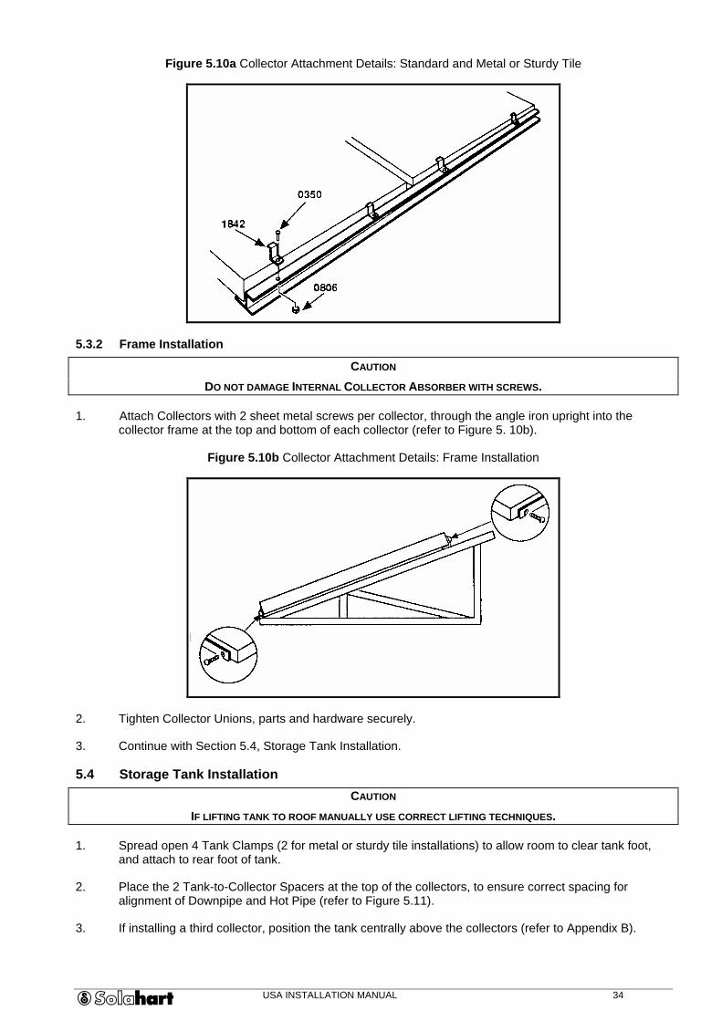
Figure 5.10a Collector Attachment Details: Standard and Metal or Sturdy Tile
5.3.2 Frame Installation
CAUTION
DO NOT DAMAGE INTERNAL COLLECTOR ABSORBER WITH SCREWS.
1. Attach Collectors with 2 sheet metal screws per collector, through the angle iron upright into the collector frame at the top and bottom of each collector (refer to Figure 5. 10b).
Figure 5.10b Collector Attachment Details: Frame Installation
2. Tighten Collector Unions, parts and hardware securely.
3. Continue with Section 5.4, Storage Tank Installation.
5.4 Storage Tank Installation
CAUTION
IF LIFTING TANK TO ROOF MANUALLY USE CORRECT LIFTING TECHNIQUES.
1. Spread open 4 Tank Clamps (2 for metal or sturdy tile installations) to allow room to clear tank foot, and attach to rear foot of tank.
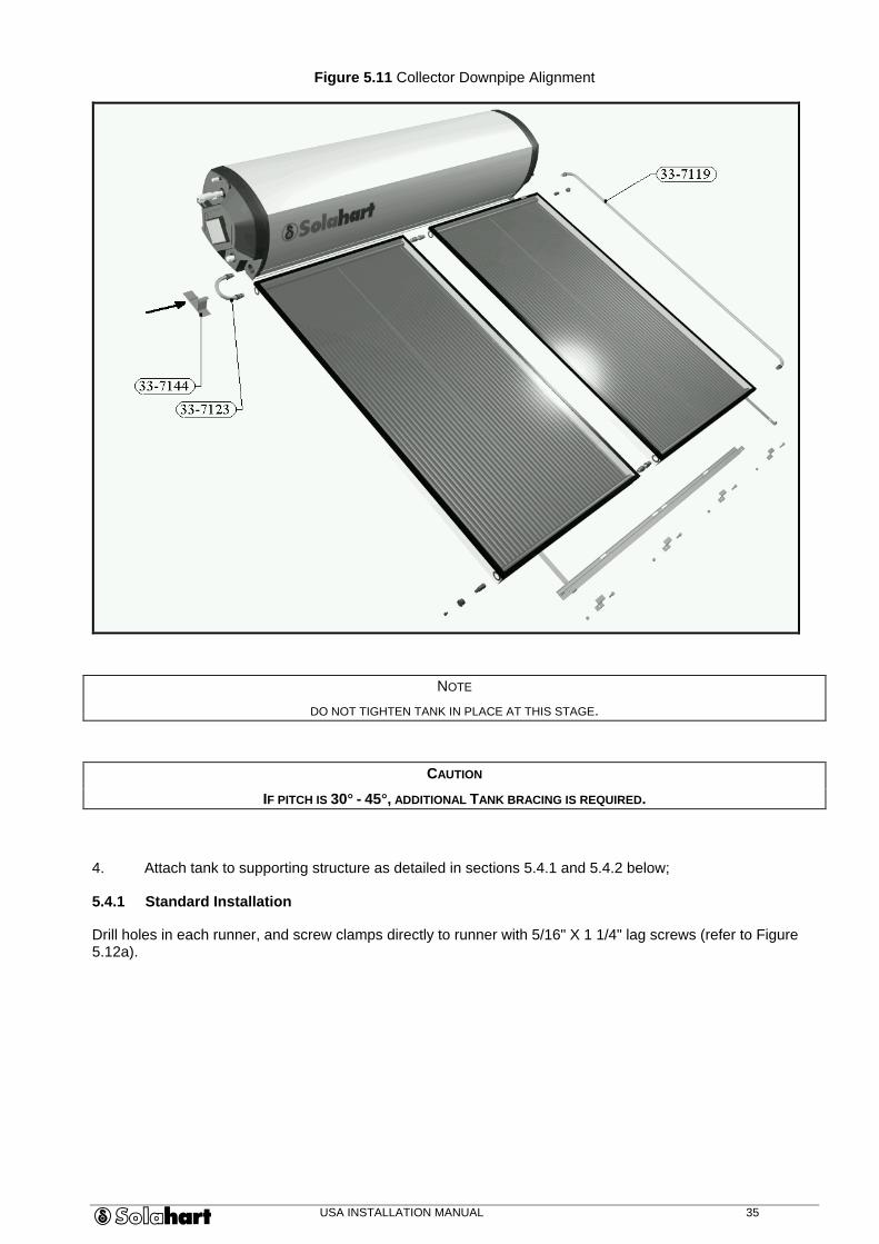
2. Place the 2 Tank-to-Collector Spacers at the top of the collectors, to ensure correct spacing for alignment of Downpipe and Hot Pipe (refer to Figure 5.11).
3. If installing a third collector, position the tank centrally above the collectors (refer to Appendix B).
USA INSTALLATION MANUAL 35
Figure 5.11 Collector Downpipe Alignment
NOTE
DO NOT TIGHTEN TANK IN PLACE AT THIS STAGE.
CAUTION
IF PITCH IS 30q - 45q, ADDITIONAL TANK BRACING IS REQUIRED.
4. Attach tank to supporting structure as detailed in sections 5.4.1 and 5.4.2 below;
5.4.1 Standard Installation
Drill holes in each runner, and screw clamps directly to runner with 5/16" X 1 1/4" lag screws (refer to Figure 5.12a).
USA INSTALLATION MANUAL 36
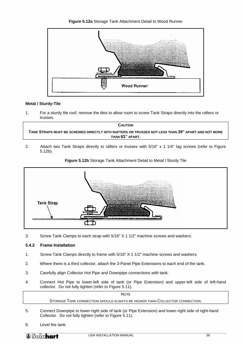
Figure 5.12a Storage Tank Attachment Detail to Wood Runner
Metal / Sturdy-Tile
1. For a sturdy tile roof, remove the tiles to allow room to screw Tank Straps directly into the rafters or trusses.
CAUTION
TANK STRAPS MUST BE SCREWED DIRECTLY INTO RAFTERS OR TRUSSES NOT LESS THAN 39" APART AND NOT MORE THAN 63” APART.
2. Attach two Tank Straps directly to rafters or trusses with 5/16" x 1 1/4" lag screws (refer to Figure 5.12b).
Figure 5.12b Storage Tank Attachment Detail to Metal l Sturdy Tile
3. Screw Tank Clamps to each strap with 5/16" X 1 1/2" machine screws and washers.
5.4.2 Frame Installation
1. Screw Tank Clamps directly to frame with 5/16" X 1 1/2" machine screws and washers.
2. Where there is a third collector, attach the 3-Panel Pipe Extensions to each end of the tank.
3. Carefully align Collector Hot Pipe and Downpipe connections with tank.
4. Connect Hot Pipe to lower-left side of tank (or Pipe Extension) and upper-left side of left-hand collector. Do not fully tighten (refer to Figure 5.11).
NOTE
STORAGE TANK CONNECTION SHOULD ALWAYS BE HIGHER THAN COLLECTOR CONNECTION.
5. Connect Downpipe to lower-right side of tank (or Pipe Extension) and lower-right side of right-hand Collector. Do not fully tighten (refer to Figure 5.11).
6. Level the tank.
USA INSTALLATION MANUAL 37
7. Tighten the tank system in place.
8. Tighten Hot Pipe and Downpipe connections.
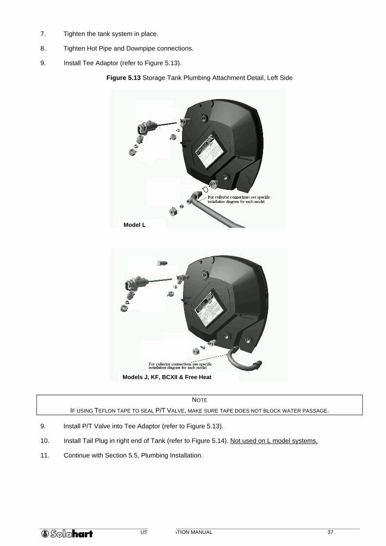
9. Install Tee Adaptor (refer to Figure 5.13).
Figure 5.13 Storage Tank Plumbing Attachment Detail, Left Side
NOTE
IF USING TEFLON TAPE TO SEAL P/T VALVE, MAKE SURE TAPE DOES NOT BLOCK WATER PASSAGE.
9. Install P/T Valve into Tee Adaptor (refer to Figure 5.13).
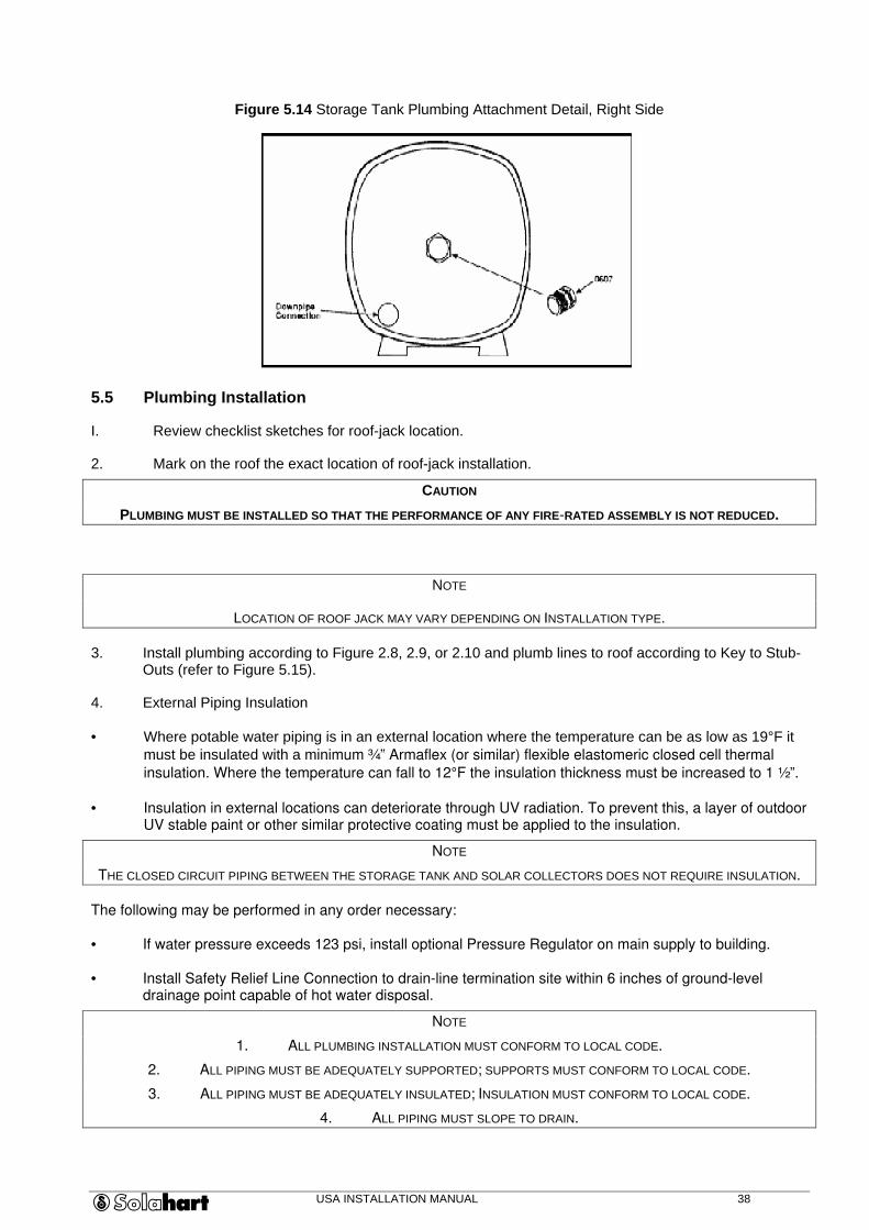
10. Install Tail Plug in right end of Tank (refer to Figure 5.14). Not used on L model systems.
11. Continue with Section 5.5, Plumbing Installation.
Model L
Models J, KF, BCXII & Free Heat
USA INSTALLATION MANUAL 38
Figure 5.14 Storage Tank Plumbing Attachment Detail, Right Side
5.5 Plumbing Installation
I. Review checklist sketches for roof-jack location.
2. Mark on the roof the exact location of roof-jack installation.
CAUTION
PLUMBING MUST BE INSTALLED SO THAT THE PERFORMANCE OF ANY FIRE-RATED ASSEMBLY IS NOT REDUCED.
NOTE
LOCATION OF ROOF JACK MAY VARY DEPENDING ON INSTALLATION TYPE.
3. Install plumbing according to Figure 2.8, 2.9, or 2.10 and plumb lines to roof according to Key to Stub-Outs (refer to Figure 5.15).
4. External Piping Insulation
• Where potable water piping is in an external location where the temperature can be as low as 19°F it must be insulated with a minimum ¾” Armaflex (or similar) flexible elastomeric closed cell thermal
insulation. Where the temperature can fall to 12°F the insulation thickness must be increased to 1 ½”.
• Insulation in external locations can deteriorate through UV radiation. To prevent this, a layer of outdoor UV stable paint or other similar protective coating must be applied to the insulation.
NOTE
THE CLOSED CIRCUIT PIPING BETWEEN THE STORAGE TANK AND SOLAR COLLECTORS DOES NOT REQUIRE INSULATION.
The following may be performed in any order necessary:
• If water pressure exceeds 123 psi, install optional Pressure Regulator on main supply to building.
• Install Safety Relief Line Connection to drain-line termination site within 6 inches of ground-level drainage point capable of hot water disposal.
NOTE
1. ALL PLUMBING INSTALLATION MUST CONFORM TO LOCAL CODE.
2. ALL PIPING MUST BE ADEQUATELY SUPPORTED; SUPPORTS MUST CONFORM TO LOCAL CODE.
3. ALL PIPING MUST BE ADEQUATELY INSULATED; INSULATION MUST CONFORM TO LOCAL CODE.
4. ALL PIPING MUST SLOPE TO DRAIN.
USA INSTALLATION MANUAL 39
5. Key to Stub - Outs
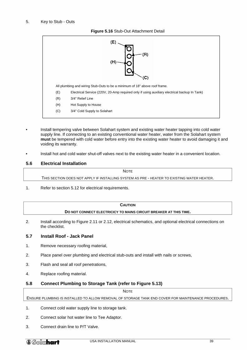
Figure 5.16 Stub-Out Attachment Detail
All plumbing and wiring Stub-Outs to be a minimum of 18" above roof frame.
(E) Electrical Service (220V, 20-Amp required only if using auxiliary electrical backup In Tank)
(R) 3/4" Relief Line
(H) Hot Supply to House
(C) 3/4" Cold Supply to Solahart
• Install tempering valve between Solahart system and existing water heater tapping into cold water supply line. If connecting to an existing conventional water heater, water from the Solahart system must be tempered with cold water before entry into the existing water heater to avoid damaging it and voiding its warranty.
• Install hot and cold water shut-off valves next to the existing water heater in a convenient location.
5.6 Electrical Installation
NOTE
THIS SECTION DOES NOT APPLY IF INSTALLING SYSTEM AS PRE - HEATER TO EXISTING WATER HEATER.
1. Refer to section 5.12 for electrical requirements.
CAUTION
DO NOT CONNECT ELECTRICICY TO MAINS CIRCUIT BREAKER AT THIS TIME.
2. Install according to Figure 2.11 or 2.12, electrical schematics, and optional electrical connections on the checklist.
5.7 Install Roof - Jack Panel
1. Remove necessary roofing material,
2. Place panel over plumbing and electrical stub-outs and install with nails or screws,
3. Flash and seal all roof penetrations,
4. Replace roofing material.
5.8 Connect Plumbing to Storage Tank (refer to Figure 5.13)
NOTE
ENSURE PLUMBING IS INSTALLED TO ALLOW REMOVAL OF STORAGE TANK END COVER FOR MAINTENANCE PROCEDURES.
1. Connect cold water supply line to storage tank.
2. Connect solar hot water line to Tee Adaptor.
3. Connect drain line to P/T Valve.
USA INSTALLATION MANUAL 40
5.9 Fill and Test Potable Water Storage Tank (All Models)
CAUTION
1. ON NEW CONSTRUCTION, DO NOT FILL STORAGE TANK AND/OR CHARGE THE CLOSED CIRCUIT SYSTEM UNTIL WATER HEATER IS READY FOR USE. COVER COLLECTORS UNTIL SYSTEM IS FILLED AND CHARGED. PLACE TAG ON
SYSTEM IF NOT FILLED AND CHARGED.
2. ON SOLAHART SYSTEMS MODEL J, KF, BCXII & FREE HEAT, DO NOT FILL THE CLOSED CIRCUIT UNTIL THE STORAGE TANK HAS BEEN FILLED AND PRESSURISED.
1. Close all hot water outlet faucets except one in a safe location (a laundry tub is usually best).
2. Open mains site water supply valve to water heater.
3. As the water heater fills, air will be pushed from the open outlet faucet. When a continuous flow of water is achieved the faucet should be closed which will pressurise the storage tank.
4. Check tank and cold water lines for leaks and repair any found. For model L systems also check the connections to and between the solar collectors.
5. Ensure that the storage tank is completely free of air by opening the P/T Valve until it discharges a steady stream of water. Then close the valve.
6. For system model L the water heater is now operational. For closed circuit system models J, KF, BCXII & Free Heat, the system is now ready to Test and Fill the closed circuit as described in Section 5.10.
5.10 Test and Fill the Closed Circuit
5.10.1 Closed Circuit Fluid (Models J, KF, BCXII & Free Heat ONLY)
The closed circuit of Solahart models J, KF, BCXII & Free Heat must be filled ONLY with Solahart Hartgard solution and potable water. Each system closed circuit is to be filled with one bottle of Hartgard and the balance potable water. When mixed the approximate Hartgard concentration is 20%.
CAUTION
UNDER NO CIRCUMSTANCES CAN ANY FLUID OTHER THAN HARTGARD BE USED.
ALTERNATE FLUIDS COULD BE HAZARDOUS TO YOUR HEALTH.
5.10.1.1 Material Safety Data
Service Temperature Range -40qF to 300qF
Viscosity approx 0.00145 Ns/m2
Freezing Point -50°F
Boiling Point 212°F
Flash Point 218°F
Auto Ignition Temperature > 750°F
Specific Heat 4190 J/kg/°C
Vapour Pressure 0.22 mm Hg @20°C
Fluid Colour Light Blue
PH Mixed 7 – 9

USA INSTALLATION MANUAL 41
5.10.1.2 First Aid
• Eye Contact: Irrigate with water for 5 minutes
• Skin Contact: Wash with flowing water or shower
• Inhalation: No adverse effects
• Ingestion: No adverse effects
• Advice to Doctor: Treatment based on judgement of doctor in response to patient reaction
5.10.1.3 Disposal of Fluid
Reprocess or burn in an approved incinerator in accordance with State/Local Government requirements.
5.10.2 Test and Fill Procedure
Remove the Fill Plug from the collector fill assembly.
Remove PR6 Jacket Relief Valve from the tank.
Connect a 1/2” hose and fill the closed circuit with water.
Continue filling until the water overflows
from the PR6 Jacket Relief Valve port
and air bubbles stop.
Fit the Test Block into the PR6 Port.
Fit the PR6 Jacket Relief Valve onto the Test Block.
1
2
3
4
USA INSTALLATION MANUAL 42
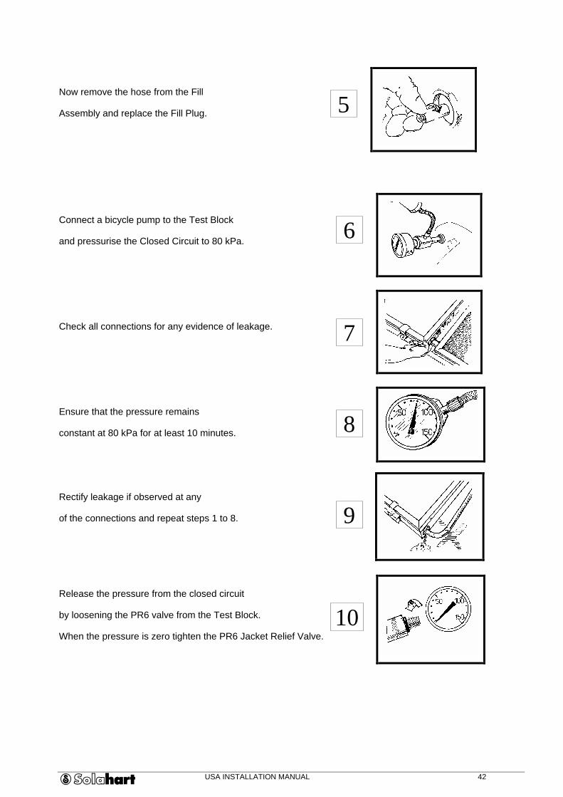
Now remove the hose from the Fill
Assembly and replace the Fill Plug.
Connect a bicycle pump to the Test Block
and pressurise the Closed Circuit to 80 kPa.
Check all connections for any evidence of leakage.
Ensure that the pressure remains
constant at 80 kPa for at least 10 minutes.
Rectify leakage if observed at any
of the connections and repeat steps 1 to 8.
Release the pressure from the closed circuit
by loosening the PR6 valve from the Test Block.
When the pressure is zero tighten the PR6 Jacket Relief Valve.
6
7
8
9
5
10
USA INSTALLATION MANUAL 43
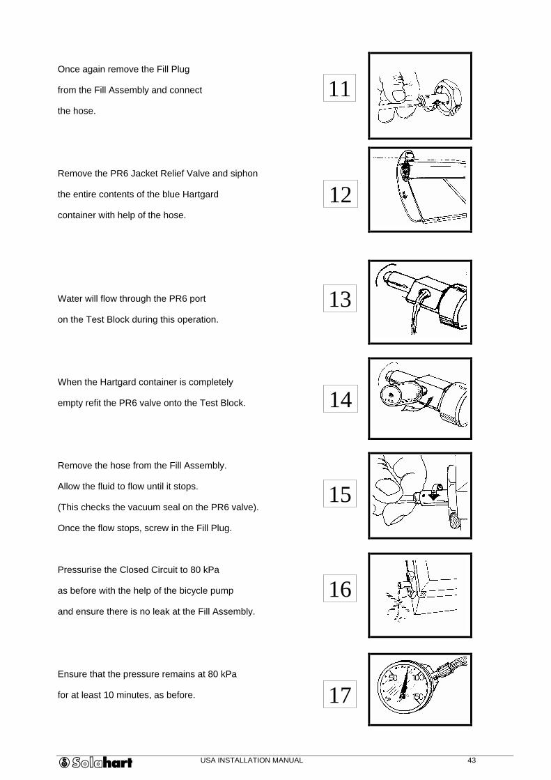
Once again remove the Fill Plug
from the Fill Assembly and connect
the hose.
Remove the PR6 Jacket Relief Valve and siphon
the entire contents of the blue Hartgard
container with help of the hose.
Water will flow through the PR6 port
on the Test Block during this operation.
When the Hartgard container is completely
empty refit the PR6 valve onto the Test Block.
Remove the hose from the Fill Assembly.
Allow the fluid to flow until it stops.
(This checks the vacuum seal on the PR6 valve).
Once the flow stops, screw in the Fill Plug.
Pressurise the Closed Circuit to 80 kPa
as before with the help of the bicycle pump
and ensure there is no leak at the Fill Assembly.
Ensure that the pressure remains at 80 kPa
for at least 10 minutes, as before.
11
16
12
17
13
14
15

USA INSTALLATION MANUAL 44
Release the pressure from the closed circuit
by removing the PR6 Valve from the Test Block.
Remove the Test Block from the Tank.
Fit the PR6 Valve in its place on the tank
after ensuring that the “O” ring is in its seat.
18
19
20
USA INSTALLATION MANUAL 45
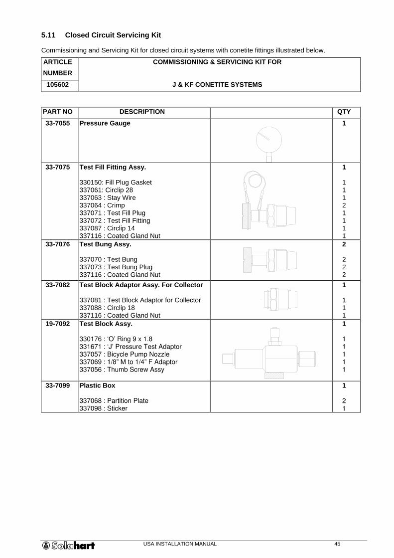
5.11 Closed Circuit Servicing Kit
Commissioning and Servicing Kit for closed circuit systems with conetite fittings illustrated below.
ARTICLE
NUMBER
COMMISSIONING & SERVICING KIT FOR
105602 J & KF CONETITE SYSTEMS
PART NO DESCRIPTION QTY
33-7055 Pressure Gauge
1
33-7075 Test Fill Fitting Assy. 330150: Fill Plug Gasket 337061: Circlip 28 337063 : Stay Wire 337064 : Crimp 337071 : Test Fill Plug 337072 : Test Fill Fitting 337087 : Circlip 14 337116 : Coated Gland Nut
1
1 1 1 2 1 1 1 1
33-7076 Test Bung Assy. 337070 : Test Bung 337073 : Test Bung Plug 337116 : Coated Gland Nut
2
2 2 2
33-7082 Test Block Adaptor Assy. For Collector 337081 : Test Block Adaptor for Collector 337088 : Circlip 18 337116 : Coated Gland Nut
1
1 1 1
19-7092 Test Block Assy. 330176 : ‘O’ Ring 9 x 1.8 331671 : ‘J’ Pressure Test Adaptor 337057 : Bicycle Pump Nozzle 337069 : 1/8” M to 1/4” F Adaptor 337056 : Thumb Screw Assy
1
1 1 1 1 1
33-7099 Plastic Box 337068 : Partition Plate 337098 : Sticker
1
2 1
USA INSTALLATION MANUAL 46
5.12 Connect Storage Tank to Electrical Supply
WARNING
TURN OFF ALL POWER TO AVOID INJURY.
CAUTION
TO REDUCE THE RISK OF ELECTRIC SHOCK OR FIRE:
• USE ONLY ON A UTILITY SUPPLY HAVING A MAXIMUM 125 / 250 VOLT, THREE WIRE SYSTEM.
• THE WATER HEATER MUST ALWAYS BE CONNECTED TO GROUND IN ACCORDANCE WITH THE LOCAL CODES.
• CONNECT BRANCH CIRCUIT EQUIPMENT GROUNDING MEANS AND SYSTEM GROUNDING CONDUCTORS TO WATER HEATER AT THE TERMINAL MARKED “G”.
• USE ONLY COPPERS CONDUCTORS.
1. Turn OFF mains site electrical power.
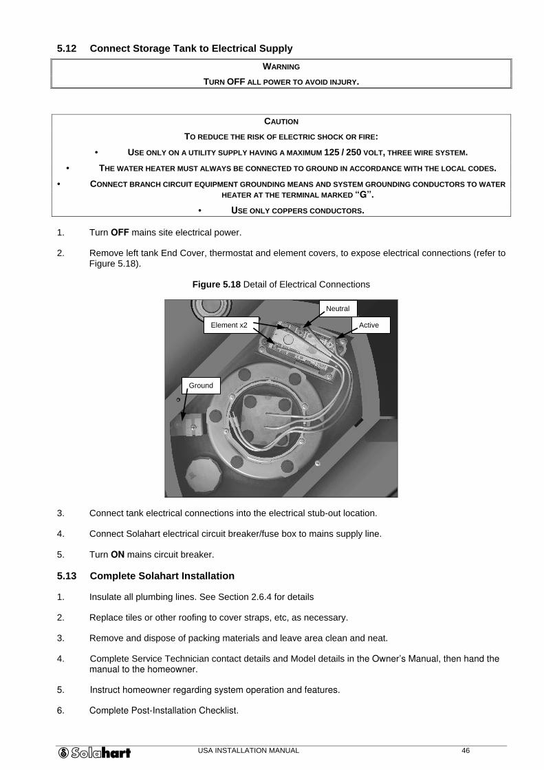
2. Remove left tank End Cover, thermostat and element covers, to expose electrical connections (refer to Figure 5.18).
Figure 5.18 Detail of Electrical Connections
3. Connect tank electrical connections into the electrical stub-out location.
4. Connect Solahart electrical circuit breaker/fuse box to mains supply line.
5. Turn ON mains circuit breaker.
5.13 Complete Solahart Installation
1. Insulate all plumbing lines. See Section 2.6.4 for details
2. Replace tiles or other roofing to cover straps, etc, as necessary.
3. Remove and dispose of packing materials and leave area clean and neat.
4. Complete Service Technician contact details and Model details in the Owner’s Manual, then hand the manual to the homeowner.
5. Instruct homeowner regarding system operation and features.
6. Complete Post-Installation Checklist.
Active
Neutral
Element x2
Ground

USA INSTALLATION MANUAL 47
6.0 TROUBLESHOOTING
This section covers problems you my experience while installing or maintaining the Solahart system.
CAUTION
REVIEW SECTION 3.0, HAZARDS AND PRECAUTIONS, BEFORE PROCEEDING WITH ANY TROUBLESHOOTING.
SYMPTOM: Insufficient Hot Water Possible Cause Corrective Action Convenience switch for Backup Heating Element OFF/malfunction
Turn convenience switch ON Repair/replace as necessary
Timer set incorrectly Reset timer Roof-mounted disconnect switch OFF/ malfunction
Turn disconnect switch ON Repair/replace as necessary
Solar circuit breaker tripped / fuse blown Reset/replace as necessary Safety Thermostat tripped/malfunction Reset/replace as necessary according to Procedure 7.2.4 Faulty Timer Unit Repair/replace as necessary Faulty Backup Heating Element Replace Backup Heating Element Hot water leak in household system Locate and repair leak Blockage in water line Locate and correct blockages Pipes not properly connected during installation
Correct pipe connections according to installation instructions
Tank blocked with sediment Flush tank to remove sediment Closed circuit charge low Recharge closed circuit Leak in closed circuit Locate and repair as necessary, recharge closed circuit Air bubbles in closed circuit Recharge closed circuit Ruptured tank jacket Replace tank Tank not level Level tank Collectors not level Level collectors Collectors shaded during daylight hours Clear obstruction to sunlight on collectors Tempering Valve malfunction Repair/replace as necessary
SYMPTOM: Insufficient Hot Water in Morning or Following a Cloudy Day Possible Cause Corrective Action Convenience switch for Backup Heating Element OFF / malfunction
Turn convenience switch ON Repair/replace as necessary
Timer set incorrectly Reset Timer Roof-mounted disconnect switch OFF/ malfunction
Turn disconnect switch ON Repair/replace as necessary
System circuit breaker tripped Repair/replace as necessary Safety Thermostat switch tripped/malfunction Reset safety cutout switch
Replace as necessary according to Procedure 7.2.4 Faulty Timer Unit Replace Faulty Backup Heating Element Replace according to Procedure 7.2.5

USA INSTALLATION MANUAL 48
SYMPTOM: Excessive Cold Water Discharging from Drain Line Possible Cause Corrective Action No P/T Valve installed Install P/T according to
Procedure 7.2.7 Excessive pressure through P/T Valve Repair/ replace as necessary Faulty Cold Water Expansion Valve Repair/ replace as necessary Pressure build up from non-Solahart source Repair plumbing as necessary SYMPTOM: Hot Water discharging from Drain Line Possible Cause Corrective Action Timer incorrectly set so that backup Heater is on during hottest part of day
Reset timer
Faulty Safety Thermostat Repair/ replace as necessary Malfunctioning P/T valve Press and release P/T valve handle to reseat valve
Repair/ replace as necessary System oversized for customer requirements Fit a Solahart Hest Dissipater Unit / cover a solar
collector / contact Solahart Dealer SYMPTOM: No Hot Water Possible Cause Corrective Action Hot Water Tempering Valve fouled Repair/ replace as necessary Pressure imbalance (over 5 psi) Between hot and cold water lines
Locate and repair cause of imbalance
Fouled Pressure Regulator Valve Repair/ replace as necessary Cold water line blocked Repair as necessary SYMPTOM: Low Hot Water Pressure Possible Cause Corrective Action Fouled Pressure Limiting Valve / Strainer Repair/ replace as necessary SYMPTOM: Water Too Hot Possible Cause Corrective Action Tempering Valve malfunction Repair/ replace as necessary SYMPTOM: Severe Noise or Knocking When Water is Turned ON or OFF Possible Cause Corrective Action Pipes not solidly clamped down Repair as necessary Faulty washer(s) in outlet faucets Repair as necessary Other plumbing problem Repair as necessary SYMPTOM: Gas Discharge from Hot Water Tap Possible Cause Corrective Action Result of system operating but water not being used
Run tap to allow gas to escape
Corroded Anode Replace according to Procedure 7.2.6
USA INSTALLATION MANUAL 49
7.0 MAINTENANCE
This section covers scheduled inspections, maintenance and detailed procedures for disassembly and repair of the Solahart system.
CAUTION
• ONLY QUALIFIED PERSONNEL SHOULD PERFORM PERIODIC MAINTENANCE.
• FOLLOW THE INSTRUCTIONS IN THIS SECTION AS CLOSELY AS POSSIBLE. IF YOU ARE UNSURE OF ANY INSTRUCTIONS OR PROCEDURES, PLEASE CONTACT A SOLAHART DEALER.
• USE OF ANY OTHER THAN SOLAHART REPLACEMENT PARTS WILL VOID THE MANUFACTURERS WARRANTY AND MAY CAUSE SYSTEM MALFUNCTIONS.
• REFER TO SECTION 3.0, HAZARDS AND PRECAUTIONS, BEFORE PROCEEDING WITH ANY MAINTENANCE.
7.1 Periodic Maintenance
To keep the Solahart system working efficiently, perform the following maintenance schedules:
7.1.1 Quarterly
CAUTION
COLLECTORS MUST BE COOL BEFORE WASHING.
1. Clean collector glass periodically to remove accumulated dust and dirt.
2. Trim trees near collectors.
7.1.2 Annually
Perform the regular quarterly and annual maintenance at the same time as this maintenance.
1. Flush hot and cold water relief valves, lift valve handle - hold for 30 seconds - release to reset valve. If water flow does not stop, life and release handle repeatedly until valve resets.
2. If valve does not reset properly after a few tries, it must be removed and cleaned or replaced.
7.1.3 Every 3 to 5 Years (10 to 12 years for Free Heat, BCXII and JXII systems)
Perform the regular quarterly and annual maintenance at the same time as this maintenance.
1. Check all valves and electrical equipment.
2. Replace Anode.
3. Replace P/T Valve.
4. Check fluid level in closed circuit. Replace fluid if necessary according to Section 5.10.
NOTE
NEVER REPLACE CLOSED CIRCUIT FLUID WITH USED FLUID. ALWAYS REPLACE WITH A NEW SOLUTION OF HARTGARD AND POTABLE WATER.
5. Install new Solahart logo if necessary.

USA INSTALLATION MANUAL 50
7.2 Maintenance Procedures
NUMBER TITLE
7.2.1 Draining Storage Tank
7.2.2 Filling Storage Tank
7.2.3 Drain Closed Circuit
7.2.4 Thermostat Reset/Replacement
7.2.5 Backup Heating Element Replacement
7.2.6 Anode Replacement
7.2.7 Pressure/Temperature Relief (P/T) Valve Replacement
7.2.8 Collector Replacement
7.2.9 Storage Tank Replacement
7.2.1 Draining Storage Tank
WARNING
TURN OFF ALL POWER.
1. Cover collectors with opaque (light cannot penetrate) material.
CAUTION
BEFORE DRAINING STORAGE TANK ON CLOSED CIRCUIT MODELS, PRESSURE IN CLOSED CIRCUIT MUST BE RELIEVED OR CIRCUIT MAY COLLAPSE. THIS ACTION IS NOT REQUIRED FOR L MODELS.
2. Turn OFF Cold Water Shut-off Valve.
3. Remove PR6 Jacket Relief Valve to relieve closed-circuit pressure in J, KF, BCXII and Free Heat models only, (refer to Figure 5.13).
4. Relieve pressure in system by lifting P/T Valve handle for at least 30 seconds.
5. To Empty the storage tank (all models):
Installations with Cold Water Expansion Valve:
Lift Cold Water Expansion Valve handle allowing the tank water to flow out of the tank until it is empty.
Installations without Cold Water Expansion Valve:
a) Remove cold supply pipe from tank on roof.
b) Attach a hose to tank inlet connection to direct flow from the tank to a safe location.
c) Open a HOT faucet inside house to allow tank to drain.
6 To Empty the collectors (L models only)
1. Empty storage tank as above.
2. Remove plug from bottom right hand corner of the collector and allow the water to flow out. The water volume is ½ US Gallon per collector.
USA INSTALLATION MANUAL 51
7.2.2 Filling Storage Tank
WARNING
TURN OFF ALL POWER.
1. Place opaque (light cannot penetrate) coverings over collectors.
2. Open at least one hot water faucet, preferably over a bathtub or large sink.
3. Turn ON Cold Water Shut-off Valve.
4. When water begins to flow through hot-water faucet without airbursts, turn faucet OFF. Bleed air from all other hot water faucets.
5. Lift P/T Valve handle for at least 30 seconds.
6. Check for and repair any plumbing leaks.
7. Replace PR6 Jacket Relief Valve using new “O” ring.
8. Remove coverings from collectors.
9. Turn ON power.
7.2.3 Drain Closed Circuit
1. Carefully unscrew and remove the PR6 Jacket Relief Valve from the tank, allowing the pressure in the jacket system to normalize. Replace the PR6 Valve.
2. Remove the thumb screw from the fill fitting and connect one end of the ½” clear plastic tub (part of the commissioning kit) to the fill assembly on the bottom left hand corner of the installation. Place the other end of the tube into a clean plastic container, capable of holding all of the closed circuit fluid in the system. There are 6.5 US Gal of fluid in the closed circuit of a 302 system.
3. Place the container on the roof, such that the top of the container is below the bottom of the system. Remove the PR6 Jacket Relief Valve, and allow all of the closed circuit fluid to flow into the container. Store the container until after the repair, so that the fluid can be replaced back into the jacket.
NOTE
TO FILL AND TEST THE CLOSED CIRCUIT REFER TO SECTION 5.10.
7.2.4 Thermostat Replacement
WARNING
TURN OFF ALL POWER.
1. Remove End Cover from left end of Storage Tank.
2. Remove yellow Thermostat Enclosure Cover.
3. Disconnect electrical wires to Thermostat one at a time, noting proper connecting points for new Thermostat.
4. Install new Thermostat, connecting wires as noted.
5. Replace yellow Thermostat Enclosure Cover.
6. Replace End Cover.
7. Turn ON power.

USA INSTALLATION MANUAL 52
7.2.5 Backup Heating Element Replacement
WARNING
TURN OFF ALL POWER.
1. Cover collectors with opaque (light cannot penetrate) material.
2. Remove PR6 Jacket Relief Valve to relieve closed circuit pressure.
3. Drain storage tank according to Procedure 7.2.1.
4. Remove End Cover on left side of tank.
5. Remove yellow Element Enclosure Cover.
6. Disconnect wires from Heating Element.
5. Remove the four screws from the Element and remove the Element and seal (refer to Figure 7.1)
Figure 7.1 Heating Element Detail
8. Install new Element and new seal.
NOTE
IF THE NEW ELECTRICAL ELEMENT IS A SICKLE TYPE, THE SICKLE MUST BE INSTALLED IN THE HORIZONTAL POSITION. THIS POSITION ENSURES THAT THE UPPER SECTION OF THE TANK CAN BE ELECTRICALLY BOOSTED AND THE LOWER
SECTION IS MAINTAINED FOR SOLAR INPUT.
9. Refit the four element screws.
CAUTION
DO NOT OVER TIGHTEN THE FOUR ELEMENT SCREWS OR DAMAGE WILL OCCUR TO THE TANK AND SEAL. USE ONLY LIGHT/MEDIUM SPANNER PRESSURE. THESE SCREWS MUST BE REFITTED CORRECTLY OR THE ELEMENT FLANGE
THREADS MAY BE DAMAGED.
USA INSTALLATION MANUAL 53
10. Re-connect Element wires.
11. Replace yellow Element Enclosure Cover
12. Replace tank End Cover.
13. Refit PR6 Jacket Relief Valve.
14. Fill Tank according to Procedure 7.2.2.
15. Turn ON power.
16. Uncover collectors.
17. Check for leaks around element seal.
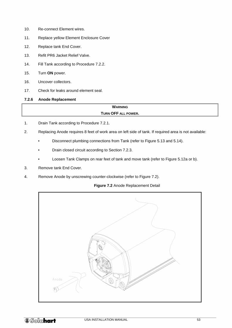
7.2.6 Anode Replacement
WARNING
TURN OFF ALL POWER.
1. Drain Tank according to Procedure 7.2.1.
2. Replacing Anode requires 8 feet of work area on left side of tank. If required area is not available:
• Disconnect plumbing connections from Tank (refer to Figure 5.13 and 5.14).
• Drain closed circuit according to Section 7.2.3.
• Loosen Tank Clamps on rear feet of tank and move tank (refer to Figure 5.12a or b).
3. Remove tank End Cover.
4. Remove Anode by unscrewing counter-clockwise (refer to Figure 7.2).
Figure 7.2 Anode Replacement Detail

USA INSTALLATION MANUAL 54
5. Insert replacement Anode.
6. Tighten Anode, taking care not to strip threads.
NOTE
IF YOU MOVED TANK, REPLACE IN ORIGINAL POSITION, REATTACH TANK CLAMPS, DOWNPIPE AND HOT PIPE.
CHARGE CLOSED CIRCUIT ACCORDING TO SECTION 5.11.
7. Refill tank according to Section 7.2.2.
8. Check for leaks.
9. Replace tank End Cover.
10. Turn ON power.
7.2.7 Pressure-Temperature Relief (P/T) Valve Replacement
1. Turn OFF water to system at Cold Water Shut-off Valve.
2. Remove PR6 Jacket Relief Valve to relieve closed-circuit pressure (refer to Figure 5.13).
3. Relieve pressure in system by lifting P/T Valve handle for at least 30 seconds.
4. Disconnect drain line and unscrew P/T Valve (refer to Figure 5.13).
WARNING
A SMALL AMOUNT OF HOT WATER MAY FLOW FROM THE TANK OUTLET SOCKET WHEN THE VALVE IS REMOVED. CARE SHOULD BE TAKEN TO AVOID SCALDING.
5. Install replacement P/T Valve and tighten into place.
6. Reconnect drain line.
7. Turn ON water and check for leaks.
7.2.8 Collector Replacement
WARNING
TURN OFF ALL POWER.
1. Cover ALL collectors with opaque (light cannot penetrate) material.
2. Drain closed circuit according to Section 7.2.3 (not applicable for L Model Systems).
3. For L Model Systems, turn OFF mains water supply and drain tank and collectors according to Section 7.2.1.
4. Disconnect pipe work and remove mounting brackets on the damaged collector(s).
5. Remove damaged collector (refer to Figures 5.9 and 5.10).
6. Place new collector on supporting structure using bottom support extrusion as a guide.
7. Position overhang to match existing collector.
CAUTION
USE ONLY MANUFACTURER-SUPPLIED HARTGARD.
8. Remove plugs from ends of replacement collector.
9. Connect Collector Unions between upper and lower inside collector ends.
10. If the replacement collector is on the LHS of the collector bank reinstall Fill Assembly, Collector Nut, and Hot Pipe (refer to Figure 5.9).
USA INSTALLATION MANUAL 55
11. If the replacement collector is on the RHS of the collector bank, reinstall Downpipe and Plug Assembly (refer to Figure 5.14).
12. If the replacement collector is the centre collector (3-panel system), reinstall Collector Unions.
13. Tighten Collector Unions and related parts.
14. Level collectors.
15. Attach collector to supporting structure.
16. For L Model Systems, turn ON mains water supply and fill tank and collectors in accordance with Section 7.2.2.
17. Test and charge closed circuit according to Section 5.11.
18. Turn ON power.
19. Remove coverings from collectors.
20. Check for leaks.
7.2.9 Storage Tank Replacement
WARNING
TURN OFF ALL POWER.
1. Cover ALL collectors with opaque (light cannot penetrate) material.
2. Drain closed circuit according to Section 7.2.3 (not applicable to L Model Systems).
3. Drain tank according to procedure 7.2.1.
4. Remove End Cover and yellow Thermostat and Element Enclosure Covers from left side of tank to expose electrical connections.
5. Mark and disconnect tank electrical connections (refer to Figure 5.18).
6. Mark and disconnect tank plumbing connections (refer to Figure 5.13 and 5.14).
7. Loosen tank from supporting structure (refer to Figure 5.12a or b).
CAUTION
IF LIFTING TANK TO OR FROM THE ROOF MANUALLY, USE CORRECT LIFTING TECHNIQUES.
8. Remove and discard old tank.
9. Place new tank on roof, using care to avoid site damage.
10. Move tank into location.
11. Be sure Hot Pipe and Downpipe connections are properly aligned with the replacement tank.
12. For three collector systems, attach 3-Panel Pipe Extensions to cold side of tank.
13. Connect Hot Pipe to lower-left side of tank, or Pipe Extension for three panel systems (not applicable to L Model Systems). DO NOT fully tighten connection.
14. Connect Downpipe to the lower-right side of tank or Pipe Extension (not applicable to L Model Systems). DO NOT fully tighten connection.
15. For L Model Systems, connect Hot Pipe to tail socket on RHS of tank or Pipe Extension for three panel systems. DO NOT fully tighten connection.
16. For L Model Systems, connect Downpipe to cold inlet socket on LHS of tank or Pipe Extension. DO NOT fully tighten connection.

USA INSTALLATION MANUAL 56
17. Level the tank.
18. Secure tank to supporting structure.
19. Tighten Hot Pipe and Downpipe connections to tank.
20. Install Tee Adaptor (refer to Figure 5.13).
21. Install P/T Valve (refer to Figure 5.13). Use Teflon tape to seal threads; avoid blocking water flow.
22. Install PR6 Jacket Relief Valve and ’O’ ring (refer to Figure 5.13).
23. Install Tail Plug (refer to Figure 5.14) or Heat Dissipater Unit (not applicable to L Model Systems).
24. Connect cold water supply line (refer to Figure 5.16).
25. Connect solar hot water line (refer to Figure 5.16).
26. Connect drain line to P/T Valve (refer to Figure 5.16).
27. Fill storage tank according to procedure 7.2.2.
28. Charge and test closed circuit according to Section 5.10.
29. Remove left End Cover and yellow Thermostat and Element Enclosure Covers from tank to expose electrical connections.
30. Connect tank electrical connections to electrical stub-out connections.
31. Turn ON power and check for proper operation.
32. Replace left End Cover and yellow Thermostat and Element Enclosure Covers on tank.
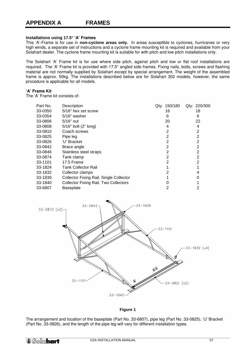
USA INSTALLATION MANUAL 57
APPENDIX A FRAMES
Installations using 17.5q ‘A’ Frames This ‘A’-Frame is for use in non-cyclone areas only. In areas susceptible to cyclones, hurricanes or very high winds, a separate set of instructions and a cyclone frame mounting kit is required and available from your Solahart dealer. The cyclone frame mounting kit is suitable for with pitch and low pitch installations only. The Solahart ‘A’ Frame kit is for use where side pitch, against pitch and low or flat roof installations are
required. The ‘A’ Frame kit is provided with 17.5° angled side frames. Fixing nails, bolts, screws and flashing
material are not normally supplied by Solahart except by special arrangement. The weight of the assembled frame is approx. 50kg. The installations described below are for Solahart 302 models, however, the same procedure is applicable for all models. ‘A’ Frame Kit The ‘A’ Frame kit consists of:
Part No. Description Qty: 150/180 Qty: 220/30033-0350 5/16" hex set screw 16 1833-0354 5/16" washer 6 633-0806 5/16" nut 20 2233-0808 5/16" bolt (2" long) 4 433-0810 Coach screws 2 233-0825 Pipe leg 2 233-0826 ’U’ Bracket 2 233-0842 Brace angle 2 233-0846 Stainless steel straps 2 233-0874 Tank clamp 2 233-1101 17.5 Frame 2 233-1824 Tank Collector Rail 1 133-1832 Collector clamps 2 433-1839 Collector Fixing Rail, Single Collector 1 033-1840 Collector Fixing Rail, Two Collectors 0 133-6807 Baseplate 2 2
Figure 1
The arrangement and location of the baseplate (Part No. 33-6807), pipe leg (Part No. 33-0825), ‘U’ Bracket (Part No. 33-0826), and the length of the pipe leg will vary for different installation types.

USA INSTALLATION MANUAL 58
Side Pitch Installations (Tiled Roof) Assemble the ‘A’ Frame kit and loosely bolt the baseplate to one side of the angle frame as per Figure 2. For
installations on a roof with a pitch of greater than 20°, a ‘U’ bracket and small pipe legs should be used on top
of the baseplate as shown in figure 3. Note that the baseplate is positioned towards the rear of the frame to distribute the weight of the tank more evenly. Remove several roofing tiles to expose the outer wall. Fix the ‘U’ brackets to the top of the wall plate and secure with the coach screws supplied (refer to figure 4 for method).
Figure 2
Using the assembled stand in a level position, measure the required length for the pipe legs, allowing for the inside length of the pipe leg cradle. Cut the two pipe legs the same length. Fit the pipe legs to the ‘U’bracket using the 5/16” x 2” bolts. Insert the pipe legs to the assembled stand and fit the 5/16 x 2” bolts. Remove tiles from above the baseplate to expose the rafters. Fix the two stainless steel straps (Part No. 33-0846) onto the baseplate and fix the straps to the rafters as shown in figure 3. Replace the tiles. Replace the tiles to the lower portion of the roof, then weather seal and overflash the penetrations through the roof (refer to figure 7). Position the collectors centrally on the frame. Check that the collector is level across the frame using a spirit level. Secure the collector in place using the collector clamps (Part No. 33-1842). Fit the tank and the fittings to the frame as per the standard installation instructions. However, fit the aluminium tank clamps onto both rear and front feet of the tank base.
Figure 3
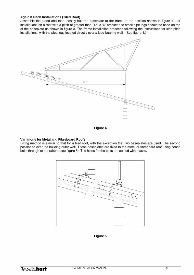
USA INSTALLATION MANUAL 59
Against Pitch Installations (Tiled Roof) Assemble the stand and then loosely bolt the baseplate to the frame in the position shown in figure 1. For installations on a roof with a pitch of greater than 20°, a ‘U’ bracket and small pipe legs should be used on top
of the baseplate as shown in figure 3. The frame installation proceeds following the instructions for side pitch installations, with the pipe legs located directly over a load-bearing wall. (See figure 4.)
Figure 4 Variations for Metal and Fibreboard Roofs Fixing method is similar to that for a tiled roof, with the exception that two baseplates are used. The second positioned over the building outer wall. These baseplates are fixed to the metal or fibreboard roof using coach bolts through to the rafters (see figure 5). The holes for the bolts are sealed with mastic.
Figure 5
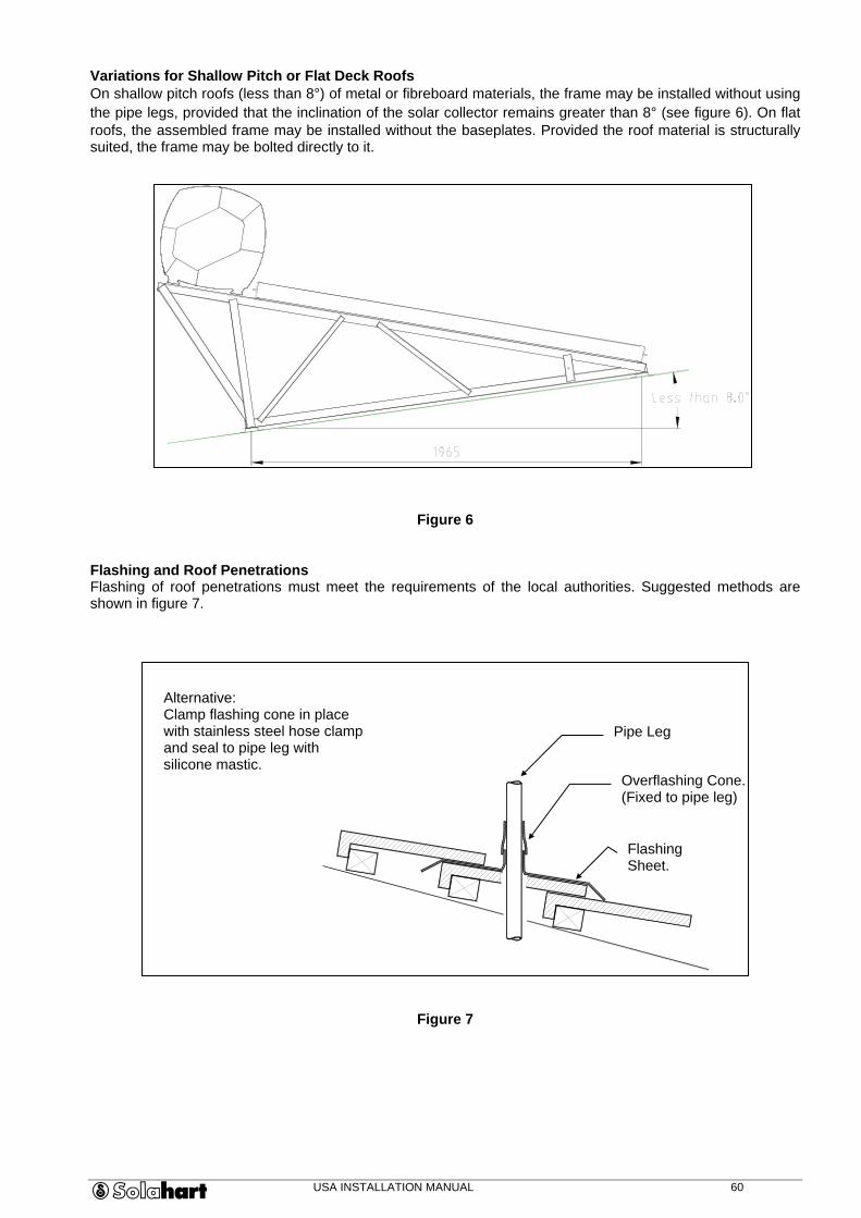
USA INSTALLATION MANUAL 60
Variations for Shallow Pitch or Flat Deck Roofs On shallow pitch roofs (less than 8°) of metal or fibreboard materials, the frame may be installed without using the pipe legs, provided that the inclination of the solar collector remains greater than 8° (see figure 6). On flat roofs, the assembled frame may be installed without the baseplates. Provided the roof material is structurally suited, the frame may be bolted directly to it.
Figure 6 Flashing and Roof Penetrations Flashing of roof penetrations must meet the requirements of the local authorities. Suggested methods are shown in figure 7.
Figure 7
Alternative: Clamp flashing cone in place with stainless steel hose clamp and seal to pipe leg with silicone mastic.
Flashing Sheet.
Pipe Leg
Overflashing Cone. (Fixed to pipe leg)
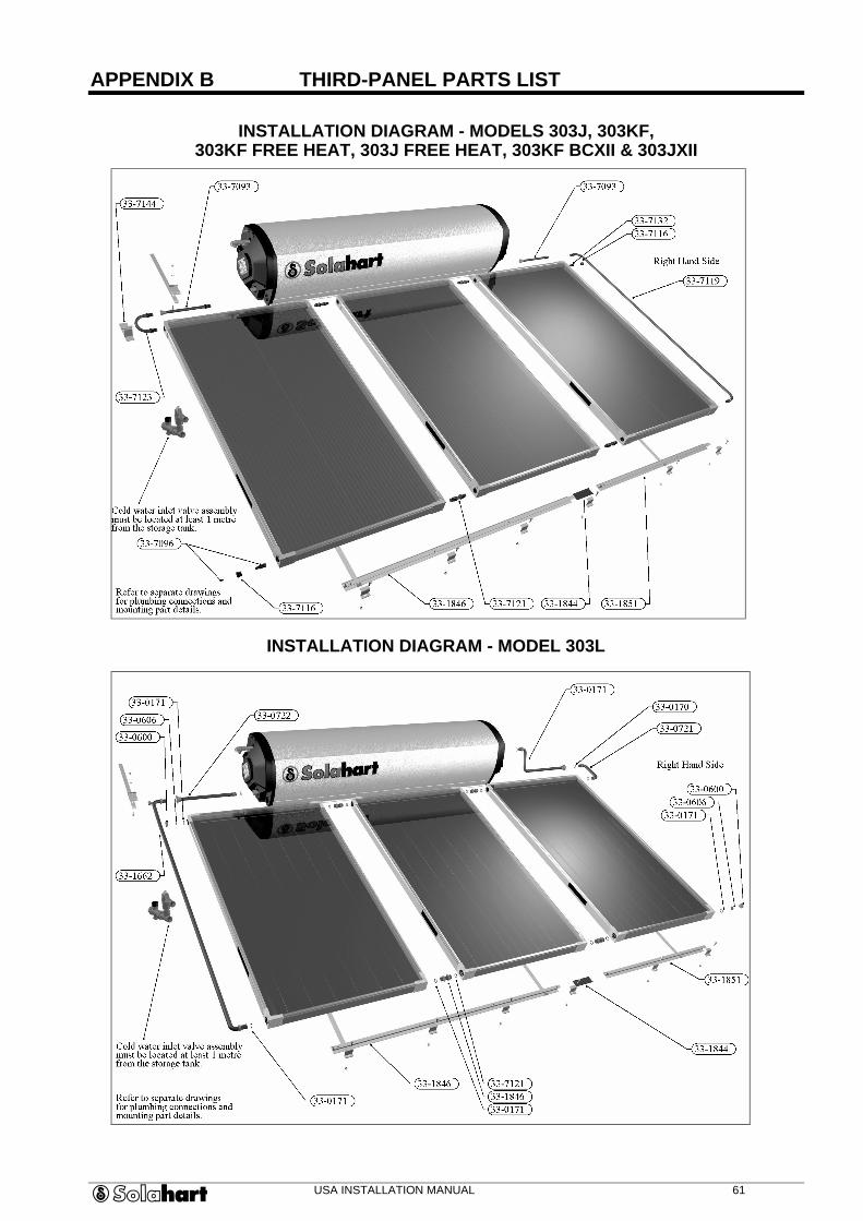
USA INSTALLATION MANUAL 61
APPENDIX B THIRD-PANEL PARTS LIST
INSTALLATION DIAGRAM - MODELS 303J, 303KF,
303KF FREE HEAT, 303J FREE HEAT, 303KF BCXII & 303JXII
INSTALLATION DIAGRAM - MODEL 303L