solar water heating training manual for the kenyan …...3.7. water heating techniques using solar...
TRANSCRIPT

Solar Water Heating Training Manual for the Kenyan Industry


Solar Water Heating Training Manual
for the Kenyan Industry
Copyright © 2017 Government of Kenya
To obtain copies of this publication, please contact:
The Principal SecretaryState Department of EnvironmentMinistry of Environment and Natural Resources Email: [email protected]: www.environment.go.ke
Director GeneralNational Industrial Training Authority Email: [email protected]: www.nita.go.ke
Reproduction of this publication for educational or non-commercial purposes is authorized without written permission from the copyright holder provided the source is fully acknowledged. Reproduction of this publication for resale or other commercial purposes is strictly prohibited without prior written permission from the copyright holder.

SOLAR WATER HEATING TRAINING MANUAL FOR THE KENYAN INDUSTRY
III
Contents
1. Introduction 1 1.1. Applications of solar energy 1
1.2. Difference between solar thermal and solar photovoltaic systems 1 1.2.1. Solar photovoltaic (PV) 1 1.2.2. Solar thermal (Solar water heating) 2
1.3. Significance of solar water heating systems 3 1.3.1. Economic impact (national outlook) 4 1.3.2 Consumer perspective 5
1.4. Regulatory requirements for solar water heating in Kenya 6
1.5. Incentives for solar water heating systems in Kenya 6
2. Occupational Safety& Health (OSH) 7 2.1. Introduction 7
2.2. Site risk assessment 7 2.2.1. Identification of hazards 7
2.3. Job risk assessment 8 2.3.1. How to assess the Risks 8 2.3.2. Severity of the hazard 9 2.3.3. Risk rating 10 2.3.4. Risk assessment matrix 11
2.4. Personal Protective equipment 12
2.5. Site safety resources 13
3. Solar Science and Technology 14 3.1. The solar resource 14
3.2. Solar radiation in Kenya 15
3.3. The path of the sun in Kenya 16
3.4. Orientation and Inclination 18 3.4.1. Orientation 18 3.4.2. Inclination and tilt angle 18
3.5. Local Climate effects and man-made features 19
3.5.1. The Effects of Clouds 19 3.5.2. Rains 19 3.5.3. Other obstacles 19 3.5.4. Soiling and cleaning of arrays 20

SOLAR WATER HEATING TRAINING MANUAL FOR THE KENYAN INDUSTRY
IV
3.6. Basic Heat Transfer Mechanisms 20 3.6.1. Conduction 20 3.6.2. Convection 21 3.6.3. Radiation 21
3.7. Water Heating Techniques using solar energy 22
3.8. Application of heat transfer mechanisms to the various types of solar water heaters 23
3.8.1. Passive and direct solar water heating system (thermosiphon) 23 3.8.2. Passive and indirect solar water heating system
(also thermosiphon) 23 3.8.3. Active and direct solar water heating system 24
3.9. Other important concepts used in solar water heating technology 25 3.9.1. Water stratification in the tank and hot and cold plumbing connections 25 3.9.3. Thermostatic mixing valve 26 3.9.4. The minimum Temperature 26 3.9.5. Corrosion of metals and anodic protection 26 3.9.6. Drinking water quality standards 27
4. Solar Water Heating Components 28 4.1. Collectors 28 4.1.1. Flat plate collectors 28 4.1.2. Evacuated tube collectors 29 4.1.3 Comparison between evacuated tube collectors and flat plate collectors 31
4.2. Mounts and mounting structures 33
4.3. Hot water storage tanks 34 4.3.1. Types of storage tanks 34 4.3.2. The basic structure of the tank 35
4.4. Boosting /backup heaters for SWH 35
4.5. Valves 36 4.5.1. Temperature Pressure Relief Valve 36 4.5.2. Pressure Reducing Valve 36 4.5.3. Air Bleed Valve 37 4.5.4. Non-Return Valve 37 4.5.5. Isolation gate valves 37 4.5.6. Thermosiphon Resistor (interruption) valve 37 4.5.7. Thermostatic mixing (or tempering) valve 37
4.6. SWH plumbing pipes 38
4.7. Insulation material 38
4.8. Heat exchangers 38
4.9. Heat transfer fluids 39
4.10. Pumps 39
4.11. Controllers 39
4.12. Expansion tank 40

SOLAR WATER HEATING TRAINING MANUAL FOR THE KENYAN INDUSTRY
V
5. Solar Water Heating System Design 41 5.1. System Sizing 41 5.1.1. Energy flow 41 5.1.2. Site survey 41 5.1.2. System component sizing 43 5.1.3. Storage tank size 45 5.1.4. Pumps 45
5.2. Collector connections, support system and schematic diagrams. 46 5.2.1. Water flow 46 5.2.2. Balanced connection 47 5.2.3. Collector configurations 47 5.2.4 Designing multiple Systems 48 5.2.5. Mounting structure design 49 5.2.6. Design for Installation 50 5.2.7. System design sketches 50 5.2.8. Bills of Quantities 53
6. Installation of Solar Water Heating Systems 54 6.1. Tools 54
6.2. Health and safety 55
6.3. Material checklist and design drawings 55
6.4. Mounting frames 55
6.5. Installation of collectors 56
6.6. Installation of Tanks 57
6.7. Back-up heater 57
6.8. Pipeworks 58
6.9. Insulation 58
6.10. Water supply 58
6.11. Valves 58
6.12. Pumps and controls 58
6.13. Tidying up 58
7. System Commissioning 59 7.1. What to check for during commissioning 59
7.2. End-user education 60
7.3. Commissioning documents 60

SOLAR WATER HEATING TRAINING MANUAL FOR THE KENYAN INDUSTRY
VI
8. System Maintenance and Trouble Shooting 62 8.1. System Maintenance 62
8.2. System Troubleshooting 62
9. Compliance Requirements for Solar Water Heating 65 9.1. The Energy (Solar Water Heating) Regulations 65 9.1.1. Time frame 65 9.1.2. Solar water heater installation works 65 9.1.3. Qualifications for licensing as a technician 66 9.1.4. Qualifications for licensing as a Contractor 66 9.1.5. ERC licensing Process 66 9.1.6. Premises required to install solar water heating systems 67 9.1.7. Exemption for premises 67 9.1.8. Hot water demand calculation and minimum solar contribution
guidelines 68 9.1.9. Technician and Contractor obligations upon commissioning of
a SWH system 69 9.1.10. Penalties under the regulations 69
9.2. Building Code 2009 [clause NN 31.5 (a)] 69
9.3. Occupational Safety and Health Act (OSHA) 2007 70
9.4. Environmental Management and Coordination Act 1999 70
9.5. Workman Injury Benefit Act 2007 71
9.6. The Kenyan Standard KS 1860: 2008 71 9.6.1. Scope of the Standard 71 9.6.2. Contents of the Standard 71
10. Further readings 72
11. List of contributors for the Solar Water Heating Training Manual 73

SOLAR WATER HEATING TRAINING MANUAL FOR THE KENYAN INDUSTRY
VII
Foreword
Kenya strategically lies along the equator hence receives solar radiation all year round estimated at 4-6 kilowatt hour per square meter per day. This renewable energy is adequate for both domestic and commercial water heating applications. However, the percentage of solar energy harnessed across the country remains insignificant. This has been associated with the lack of expertise to carry out installation, maintenance and repair of solar water heating technologies.
Policy intervention to address challenges of uptake of solar energy has been through the development of the Solar Water Heating Regulations, 2012 by the Energy Regulatory Commission (ERC). The regulations require that all premises within the jurisdiction of a local authority with hot water requirements of a
capacity exceeding one hundred liters per day shall install and use solar water heating systems. Further it requires that the installation of these systems be undertaken by technicians who have undergone training and awarded a license by ERC. However, the lack of a formal training manual to support the training of technicians in the country remains a challenge.
It is against this background that the Ministry of Environment and Natural Resources through the Low Emission and Climate Resilient Development project supported the development of a national training manual for solar water heating installation, maintenance and repair. The manual covers nine (9) topics ranging from the basic knowledge of the technology, solar water heating system sizing and design, installation of the systems, compliance requirements for technicians amongst others. This manual thus offers a rich source of information adequate for the delivery of essential and practical knowledge.
The manual was developed through a consultative process that entailed bringing together team of experts that generated the content based on a curriculum developed by National Industrial Training Authority (NITA). The experts were drawn from the following institutions: Jomo Kenyatta University of Agriculture and Technology, National Industrial Training Authority, Technical Vocational Education and Training Authority, Energy Regulatory Commission, Ministry of Environment and Natural Resources, Kenya Association of Manufacturers, Steelstone Kenya Ltd., Chloride Exide Ltd., Kisii University, Technical University of Kenya, Jeremiah Nyaga Technical Training Institute, Nairobi Technical Training Institute, and Kenya Industrial Training Institute. I am grateful for team members’ willingness to dedicate time and share their valuable knowledge.
I wish to commend the Institute of Energy and Environmental Technology (IEET), Jomo Kenyatta University of Agriculture and Technology, for their input and coordination towards development of the training manual.
Charles T. Sunkuli, CBSPrincipal SecretaryState Department of EnvironmentMinistry of Environment and Natural Resources

SOLAR WATER HEATING TRAINING MANUAL FOR THE KENYAN INDUSTRY
VIII
Preface
This Solar Water Heating (SWH) Manual is written in response to the licensing requirements of the Energy (Solar Water Heating) regulations of 2012, which require a given level of competency before licensing of SWH technicians. Up to now, there has been no dedicated instructional material on this subject that is relevant to the Kenyan situation. Most of the books available in the market are too general and often give illustrations that are not suitable for a tropical climate such as Kenya’s. In writing this manual, the approved National Industrial Training Authority (NITA) curriculum for solar water heating has been used.
The manual presents the content in nine (9) topics, explained in a simplified language to enable readership by any person with post-secondary school education in Physical Sciences or Engineering. Where possible, illustrations with diagrams, photographs and worked examples have been provided to improve the reader’s understanding of the issues being explained.
Chapters 1 and 2 introduce the applications of solar energy, which is the primary source of energy and has various applications including lighting and heating. Attention is then given to solar water heating applications, potential benefits of the use of the technology and issues pertaining to occupational health and safety.
Chapters 3, 4 and 5 elucidate the science of solar energy, heat transfer mechanisms and solar water heating systems. It is worth noting that system sizing and design is very crucial as each site has its own characteristics, thus considerations for sizing and design have been elaborated.
Chapters, 6, 7 and 8 focus on the installation of the systems and commissioning,which involve educating the user on use as well as handing over and maintenance of the system to ensure that the systemsfunction optimally. The final chapter of the manual focuses on compliance requirements to the various regulations that technicians must comply to; the solar water heating regulations, the building code, occupational health and safety etc.
The technicians and engineers working in the housing services sector will find the manual invaluable as a reference material when designing, installing or troubleshooting SWH systems. The manual can also be used as a course book for skills training in Technical and Vocational Education and Training Institutions where solar water heating is offered as a distinct course. A lot of input has been received from stakeholders in the field hence the content reflects the competence required both in knowledge theory and practice.
Prof. Robert KinyuaDirector Institute of Energy and Environmental Technology, Jomo Kenyatta University of Agriculture and Technology (JKUAT)
Paul KosgeiDirector GeneralNational Industrial Training Authority (NITA)

SOLAR WATER HEATING TRAINING MANUAL FOR THE KENYAN INDUSTRY
1
1. Introduction1.1. Applications of solar energyEnergy resources are broadly classified as non-renewable and renewable. Non-renewable resources, also known as conventional energy resources, are finite (exhaustible) in nature and are mainly of fossil origin. These include coal, petroleum, natural gas, nuclear, tar sands, oil shale and shale gas. Renewable energy resources on the other hand are either inexhaustible or can be replenished within a short period through natural cycles. These include solar, wind, geothermal, hydropower (hydro-electricity, tidal and wave) and biomass.
Solar energy is indeed the primary source of energy as most of the other sources are derived from it. For example, solar energy is naturally used by plants (through the process of photosynthesis) to manufacture their food, storing it in a stable chemical form. As human beings, we use the light and the heat generated by the sun for various applications, which can be classified into solar photovoltaics and solar thermal applications.
1.2. Difference between solar thermal and solar photovoltaic systemsSolar thermal and solar photovoltaics are two concepts that harness energy from the sun but have totally different application of the solar energy.
1.2.1. Solar photovoltaic (PV)Solar PV is a technology that converts solar energy to direct current (DC) electricity by exploiting the properties of certain materials technically called semiconductors (e.g. Silicon). When solar radiation falls on these materials, their atomic structures react in such a way that it generates continuous electric current. The strength of the generated current is proportional to the strength of the solar radiation: During cloudy or rainy weather, the strength of solar radiation is very low and so is the generated current.
The power generated by solar PV is used to provide electricity for many different applications. Due to the fluctuations of the strength of solar radiation, a battery is usually necessary to store the generated electricity. It is also well suited for remote regions where there are no alternative sources of electricity. To run alternating current (AC) appliances, an inverter is needed to convert the DC electricity to AC electricity.
Usually, semiconductor materials are manufactured in form of cells. Cells are then connected in series to make a solar PV module or solar panel (usually found in the shops). Solar PV modules can also be joined together in series or parallel connections to provide even large amounts of power to even megawatt (MW) capacity. Nowadays, solar PV can provide as much power as any other technology available in the market and the quality of electricity is similar to grid electricity.
There are numerous applications that this generated electricity can be used for e.g. lighting homes, providing power to (villages and grid networks), water pumping, air conditioning, powering telecommunication masts and so forth.
In the recent years, photovoltaic (PV) cells have seen quite a number of new and more advanced applications e.g. generating electricity to power electric vehicles and aeroplanes.
SOLAR WATER HEATING TRAINING MANUAL FOR THE KENYAN INDUSTRY
2
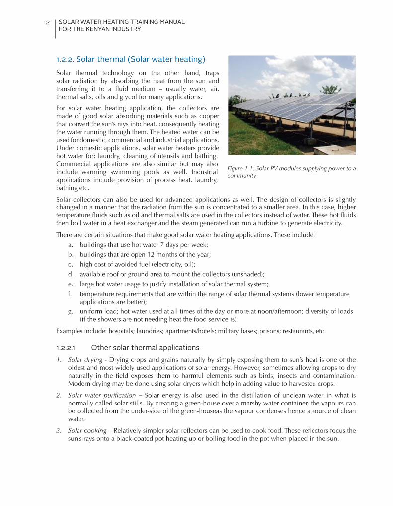
1.2.2. Solar thermal (Solar water heating)Solar thermal technology on the other hand, traps solar radiation by absorbing the heat from the sun and transferring it to a fluid medium – usually water, air, thermal salts, oils and glycol for many applications.
For solar water heating application, the collectors are made of good solar absorbing materials such as copper that convert the sun’s rays into heat, consequently heating the water running through them. The heated water can be used for domestic, commercial and industrial applications. Under domestic applications, solar water heaters provide hot water for; laundry, cleaning of utensils and bathing. Commercial applications are also similar but may also include warming swimming pools as well. Industrial applications include provision of process heat, laundry, bathing etc.
Solar collectors can also be used for advanced applications as well. The design of collectors is slightly changed in a manner that the radiation from the sun is concentrated to a smaller area. In this case, higher temperature fluids such as oil and thermal salts are used in the collectors instead of water. These hot fluids then boil water in a heat exchanger and the steam generated can run a turbine to generate electricity.
There are certain situations that make good solar water heating applications. These include: a. buildings that use hot water 7 days per week; b. buildings that are open 12 months of the year; c. high cost of avoided fuel (electricity, oil); d. available roof or ground area to mount the collectors (unshaded);e. large hot water usage to justify installation of solar thermal system;f. temperature requirements that are within the range of solar thermal systems (lower temperature
applications are better);g. uniform load; hot water used at all times of the day or more at noon/afternoon; diversity of loads
(if the showers are not needing heat the food service is)
Examples include: hospitals; laundries; apartments/hotels; military bases; prisons; restaurants, etc.
1.2.2.1 Other solar thermal applications1. Solar drying - Drying crops and grains naturally by simply exposing them to sun’s heat is one of the
oldest and most widely used applications of solar energy. However, sometimes allowing crops to dry naturally in the field exposes them to harmful elements such as birds, insects and contamination. Modern drying may be done using solar dryers which help in adding value to harvested crops.
2. Solar water purification – Solar energy is also used in the distillation of unclean water in what is normally called solar stills. By creating a green-house over a marshy water container, the vapours can be collected from the under-side of the green-houseas the vapour condenses hence a source of clean water.
3. Solar cooking – Relatively simpler solar reflectors can be used to cook food. These reflectors focus the sun’s rays onto a black-coated pot heating up or boiling food in the pot when placed in the sun.
Figure 1.1: Solar PV modules supplying power to a community

SOLAR WATER HEATING TRAINING MANUAL FOR THE KENYAN INDUSTRY
3
1.3. Significance of solar water heating systemsAn ordinary Kenyan home requires hot water for various uses. Majority of homes either use inferior sources of energy such as wood-fuel and charcoal or relatively more expensive sources such as gas and electricity to heat water. Use of electricity to heat water is becoming more common especially in single household dwellings, flats and hotels in cities as well as in institutions and industries. The demand for hot water contributes around 40%-60% of the energy bills in a typical Kenyan household.
Solar Water Heating (SWH) systems provide a very good opportunity to reduce pollution and/or economic constraints associated with the earlier mentioned sources. Despite the abundance of solar energy in the country and the high demand for hot water in both domestic and commercial fronts, the uptake level of solar water heating systems in Kenya is extremely low. Some of the challenges affecting the solar water heating industry include; lack of sensitization on the solar water heating technology, inadequate capacity and water supply.
Some of the key benefits that SWHs will offer include:
§ Development and utilization of indigenous energy resources – solar energy is the principle source of energy and the most indigenous source ever used by man-kind
§ Provision of hot water throughout the year- solar resource is relatively available all year round especially in Kenya.
§ Reduced energy bills - solar resource is free and one only needs to purchase the components
§ Reduced pressure on expensively-run power plants - resulting from increased peak demand for grid electricity partly used to heat water.
§ Reduction of carbon emission footprints - solar energy is free of carbon emissions and we get hot water which is also free of the same. By replacing or substituting the fuels used to heat water with solar energy, the amounts of carbon emissions are directly or indirectly eliminated and/or reduced.
§ Enhanced national energy security- through diversification of energy supply options and reduction in the over-reliance on petroleum and biomass use
§ Increased employment, capacity building and income generation resulting from the expanded solar water heating industry
§ Source of national revenue–SWHs provides an opportunity for the government to trade on Carbon Credits with emissions-ridden nations.
It is possible to quantify the benefits accrued from the solar water heating installations as demonstrated in the following sections.
Figure 1.2: A locally made solar drier
Figure 1.3: A foldable solar cooker
SOLAR WATER HEATING TRAINING MANUAL FOR THE KENYAN INDUSTRY
4
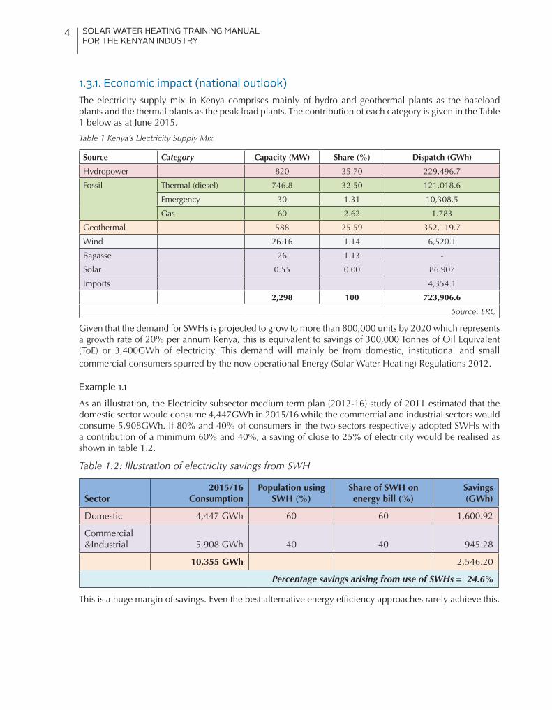
1.3.1. Economic impact (national outlook)The electricity supply mix in Kenya comprises mainly of hydro and geothermal plants as the baseload plants and the thermal plants as the peak load plants. The contribution of each category is given in the Table 1 below as at June 2015.
Table 1 Kenya’s Electricity Supply Mix
Source Category Capacity (MW) Share (%) Dispatch (GWh)
Hydropower 820 35.70 229,496.7
Fossil Thermal (diesel) 746.8 32.50 121,018.6
Emergency 30 1.31 10,308.5
Gas 60 2.62 1.783
Geothermal 588 25.59 352,119.7
Wind 26.16 1.14 6,520.1
Bagasse 26 1.13 -
Solar 0.55 0.00 86.907
Imports 4,354.1
2,298 100 723,906.6
Source: ERC
Given that the demand for SWHs is projected to grow to more than 800,000 units by 2020 which represents a growth rate of 20% per annum Kenya, this is equivalent to savings of 300,000 Tonnes of Oil Equivalent (ToE) or 3,400GWh of electricity. This demand will mainly be from domestic, institutional and small commercial consumers spurred by the now operational Energy (Solar Water Heating) Regulations 2012.
Example 1.1
As an illustration, the Electricity subsector medium term plan (2012-16) study of 2011 estimated that the domestic sector would consume 4,447GWh in 2015/16 while the commercial and industrial sectors would consume 5,908GWh. If 80% and 40% of consumers in the two sectors respectively adopted SWHs with a contribution of a minimum 60% and 40%, a saving of close to 25% of electricity would be realised as shown in table 1.2.
Table 1.2: Illustration of electricity savings from SWH
Sector2015/16
ConsumptionPopulation using
SWH (%)Share of SWH on energy bill (%)
Savings (GWh)
Domestic 4,447 GWh 60 60 1,600.92
Commercial &Industrial 5,908 GWh 40 40 945.28
10,355 GWh 2,546.20
Percentage savings arising from use of SWHs = 24.6%
This is a huge margin of savings. Even the best alternative energy efficiency approaches rarely achieve this.
SOLAR WATER HEATING TRAINING MANUAL FOR THE KENYAN INDUSTRY
5
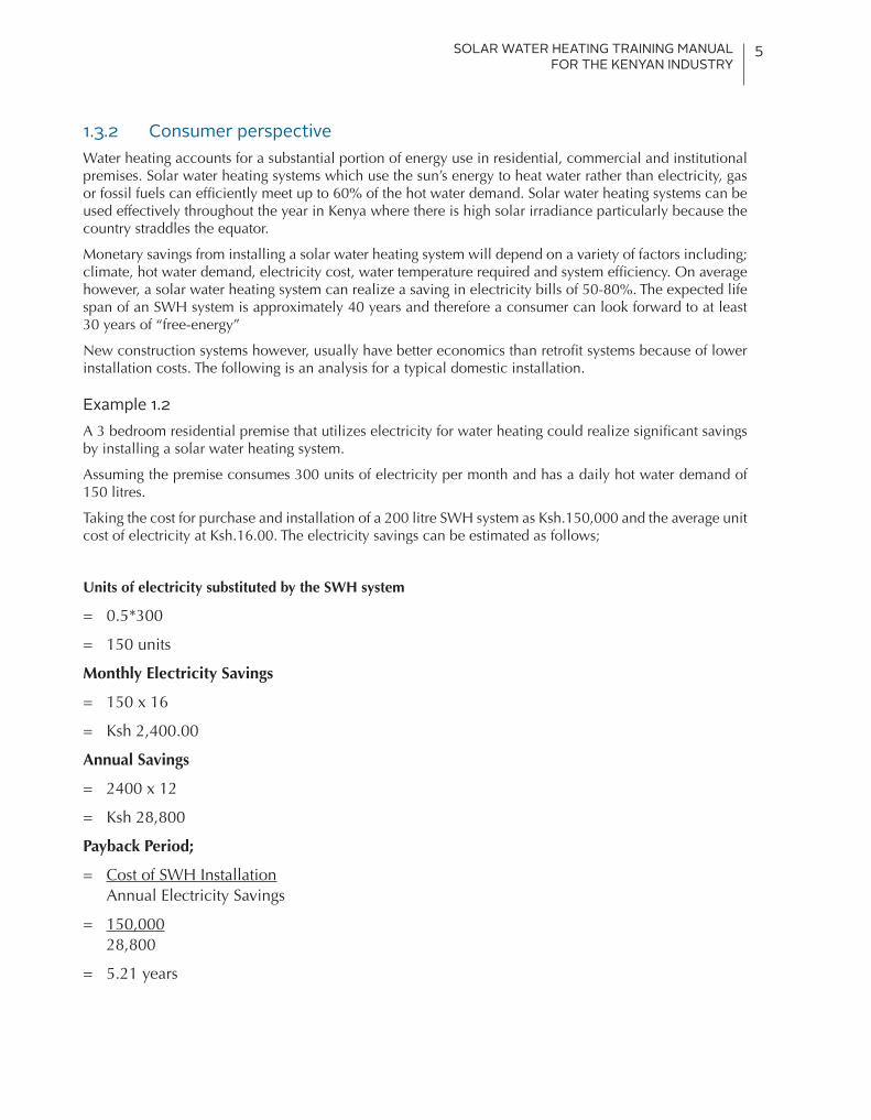
1.3.2 Consumer perspectiveWater heating accounts for a substantial portion of energy use in residential, commercial and institutional premises. Solar water heating systems which use the sun’s energy to heat water rather than electricity, gas or fossil fuels can efficiently meet up to 60% of the hot water demand. Solar water heating systems can be used effectively throughout the year in Kenya where there is high solar irradiance particularly because the country straddles the equator.
Monetary savings from installing a solar water heating system will depend on a variety of factors including; climate, hot water demand, electricity cost, water temperature required and system efficiency. On average however, a solar water heating system can realize a saving in electricity bills of 50-80%. The expected life span of an SWH system is approximately 40 years and therefore a consumer can look forward to at least 30 years of “free-energy”
New construction systems however, usually have better economics than retrofit systems because of lower installation costs. The following is an analysis for a typical domestic installation.
Example 1.2 A 3 bedroom residential premise that utilizes electricity for water heating could realize significant savings by installing a solar water heating system.
Assuming the premise consumes 300 units of electricity per month and has a daily hot water demand of 150 litres.
Taking the cost for purchase and installation of a 200 litre SWH system as Ksh.150,000 and the average unit cost of electricity at Ksh.16.00. The electricity savings can be estimated as follows;
Units of electricity substituted by the SWH system
= 0.5*300
= 150 units
Monthly Electricity Savings
= 150 x 16
= Ksh 2,400.00
Annual Savings
= 2400 x 12
= Ksh 28,800
Payback Period;
= Cost of SWH Installation Annual Electricity Savings
= 150,000 28,800
= 5.21 years

SOLAR WATER HEATING TRAINING MANUAL FOR THE KENYAN INDUSTRY
6
The customer will recover the cost of investment in about 5.2 years and thereafter enjoy free hot water. The attractive return on investment obtained from installing solar water heating systems has given rise to development of asset financing products for SWH systems by various financing institutions in Kenya e.g. Housing Finance, Equity Bank among others.
1.4. Regulatory requirements for solar water heating in Kenya
Installation of SWH systems in existing and new premises is indeed a requirement by the laws of Kenya. These requirements are derived from the Energy (Solar Water Heating) Regulations, 2012 gazetted by the Energy Regulatory Commission on 25thMay 2012 and inline with the Kenya Standards KS 1860:2009.
The Regulations require that;
§Premises within a jurisdiction of a local water authority using over 100 Litres of hot water per day are required to have a SWH system installed.
§An owner of premises, Architect and an Engineer engaged in the design, construction, extension or alteration of premises shall incorporate solar water heating systems in all new premises designs and extensions or alterations to existing premises.
§An owner or occupier of premises that have a solar water heating system shall use and carry out the necessary operational maintenance and repairs required to keep the installation in good and efficient working condition and any other premises the commission determines.
Finer details of the regulations and highlights of the standards are discussed in Chapter 9.
1.5. Incentives for solar water heating systems in Kenya
As at 2016, the only incentives in place for installation of SWH systems are duty waiver and tax exemptions. However, the existence of the regulations is also an incentive to the industrial sector. The construction industry especially the real estate sector appears to have an upper hand in accessing financing by incorporating SWHs. Financiers of real estate projects are keen and more likely to finance developers who have incorporated SWHs in their designs. Investors and potential buyers are also getting more informed and the availability of SWHs as an accessory in a home is becoming a prerequisite to many buyers. Some financial institutions are also offering loans for SWHs.
SOLAR WATER HEATING TRAINING MANUAL FOR THE KENYAN INDUSTRY
7
2. Occupational Safety& Health (OSH)2.1. IntroductionThis chapter aims at outlining the main safety and health concerns associated with the installation and commissioning of solar water heating (SWH) systems. This is not a replacement for any regulation but a guide specific to SWH and reference should be made to the Occupation Health & Safety Act 2007, Workman Injury Benefits Act, and Planning and Building regulations, 2009.
Safety is paramount to both the worker and the employer. The main goal of OSH is to promote a safe working environment. This may also protect co-workers, family members, employers, customers, and many others who might be affected by the workplace environment.
In realization to these, several things should be considered.
2.2. Site risk assessmentAn onsite assessment of risks is necessary before starting any work. This is also referred to as Job Safety Analysis. This should involve:
1. Checking and assessing the type of building that the system will be installed, possible hazards that may result and the necessary safety measures needed.
2. Determine the type of roofing or surface that the SWH will be installed such as the support structure for possible safety measure based on the slope or the surface.
3. Assessing the security of the site and determine areas that need to be cordoned off to avoid the risk of injury to workers and other people near the site.
4. Assess the type of system (whether on roof or in roof) that will be installed and institute safety measure.
To be able to adequately conduct a site risk assessment, the workers must first start by identifying all the potential hazards on site.
2.2.1. Identification of hazardsHazard identification is a major step in ensuring a safe work environment. This is mainly the first step in risk assessment. A hazard is a condition, an object, activity or event with the potential of causing injuries to personnel, damage to equipment or structures, loss of material, or reduction of ability to perform a prescribed function. E.g. working at height, slippery roof tops etc.
While a hazard is anything that may cause harm, risk is a chance which could be high or low that one could be harmed by these and other hazards with an indication of how serious the harm could be. Therefore Risk (R) is a product of Consequence (C) and Likelihood (L) (R= LXC).
Common hazards in Solar Water Heating installation and operation include:
• Working at heights
• Falling objects such tools and system components
• High temperatures of the ambient environment, roof surface or system surfaces and hot water.
• Bacteria colonies, particularly Legionella, in water that is not hot enough to kill them

SOLAR WATER HEATING TRAINING MANUAL FOR THE KENYAN INDUSTRY
8
• Structural hazards in building where the support structure may not be able to support the increased load.
• Electrical hazards such as electrical shock.
• Excessive glare from the roofing material or the system collectors
• Lifting of heavy objects
• Explosion from installed water heaters.
• Burns or igniting fire while using a torch to solder pipes in place.
• Working in confined spaces (attic, crawlspace) where fumes accumulate and escape is difficult.
These hazards may result in serious risks. Some of the most common risks in SWH systems installations are:
• Falling-caused by unsecure ladders, slippery roofs
• Burns & scalds from hot water, hot surfaces such as the roof, piping
• Cuts from sharp tools & broken collectors or roofing materials
• Electrical shocks from contact with live conductors
To duly complete these exercise, the installers working in conjunction with their supervisors must undertake a job safety analysis using a job safety checklist. These should identify the hazards, activities where the hazards may be encountered, and the people who may be affected by the hazards.
2.3. Job risk assessmentRisk assessment is the process where you identify hazards analyse or evaluate the risks associated with that hazard and determine appropriate ways to eliminate or control the hazards. Risk assessment would normally include the identified hazards, the persons who may be affected by the hazards and the measures put in place to reduce the risks. The risk assessments should be work based i.e. they should be conducted in every new site and/or when the employer thinks levels of risk have changed.
2.3.1. How to assess the Risks• Identify the hazards
• Decide who might be harmed and how
• Evaluate the risks and decide on precautions
• Record the findings
• Review the assessment if necessary and communicate to staff
Step 1 - Identifying hazards and related activities One of the most important aspects of risk assessment is accurately identifying the potential hazards in the workplace. A good starting point is to walk around the workplace and think about any hazards i.e. what is it about the activities, processes or substances used that could injure your employees or harm their health?

SOLAR WATER HEATING TRAINING MANUAL FOR THE KENYAN INDUSTRY
9
Table 2.2: Potential hazards posed by SWHs
Examples of hazards
Falling from height Manual handling
Falling objects Noise
Exposure to high temperatures Ejected materials
Glare Poor lighting
Electrical hazards
The hazards may be physical, mechanical, electrical, agronomical, biological, chemical or psychological.
Step 2 - Identifying people at risk of harm For each hazard identified, one needs to be clear on who might be harmed. This helps in identifying the best way of controlling the risk.
Table 2.3: Potential people at risk
Identify groups or people who may be affected.Examples of people at risk
Employees
Temporary workers
Members of the public
Children
Shift workers
Visitors
Step 3 - Analysing the risk To help analyse risk, a matrix scoring system can be used. Numerical scores are given to the severity and likelihood of risks and these scores are multiplied to get a rating for the risk. This means the risk rating is a measure of the likelihood that harm from a particular hazard will occur, taking into account the possible severity of such an occurrence.
Risk = Severity x Likelihood
For the initial risk evaluation, consider the risks identified in the worst case scenario before any controls are applied.
2.3.2. Severity of the hazardThe severity is expressed in terms of the effect on the person, whether injury or ill health, and ranging from minor injury to fatal injuries. Factors affecting the severity of the effects include:
• The number of people who may be affected
• Any individuals particularly at risk because of disabilities or medical conditions
• The properties of materials, speeds, heights and weights
• The amount and type of energy involved.
• The condition of equipment.
SOLAR WATER HEATING TRAINING MANUAL FOR THE KENYAN INDUSTRY
10
Table 2.4: Severity of Risk table
Hazard likelihood
Definition Points rating
Almost certain
If the work continues as it is, there is almost 100% certainty that an accident will happen, for example: • A broken stair or broken rung on a ladder • Bare, exposed electrical conductors • Unstable stacks of heavy boxes
5
Highly likely
Will happen more often than not. Additional factors could precipitate an incident but it is still likely to happen without this additional factor.
4
Possible The accident may occur if additional factors precipitate it, but it is unlikely to happen without them.
3
Unlikely This incident or illness might occur but the probability is low and the risk minimal.
2
Rare There is really no risk present. Only under freak conditions could there be any possibility of an accident or illness. All reasonable precautions have been taken - This should be the normal state of the workplace.
1
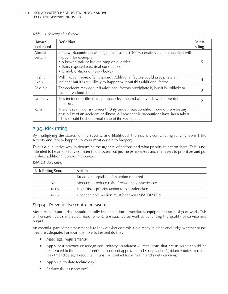
2.3.3. Risk ratingBy multiplying the scores for the severity and likelihood, the risk is given a rating ranging from 1 (no severity and rare to happen) to 25 (almost certain to happen).
This is a qualitative way to determine the urgency of actions and what priority to act on them. This is not intended to be an objective or scientific process but just helps assessors and managers to prioritize and put in place additional control measures.
Table2.5: Risk rating
Risk Rating Score Action
1-4 Broadly acceptable - No action required
5-9 Moderate - reduce risks if reasonably practicable
10-15 High Risk - priority action to be undertaken
16-25 Unacceptable -action must be taken IMMEDIATELY
Step 4 - Preventative control measures Measures to control risks should be fully integrated into procedures, equipment and design of work. This will ensure health and safety requirements are satisfied as well as benefiting the quality of service and output.
An essential part of the assessment is to look at what controls are already in place and judge whether or not they are adequate. For example, to what extent do they:
• Meet legal requirements?
• Apply best practice or recognized industry standards? - Precautions that are in place should be referenced to the manufacturer’s manual and approved codes of practice/guidance notes from the Health and Safety Executive. (If unsure, contact local health and safety services)
• Apply up–to-date technology?
• Reduce risk as necessary?

SOLAR WATER HEATING TRAINING MANUAL FOR THE KENYAN INDUSTRY
11
Step 5 - Communicating the findings Information on risks and control measures identified by the risk assessment should be communicated to employees and others as appropriate - Make copies of risk assessments available to all the employees concerned.
This communication must be easy to understand by the audience and may require the use of photographs, diagrams or a translator. You could use the information in the following ways:
• Induction training • Safe systems of work • Safety procedures • Hand books • Team briefings • Toolbox talks • Supervision meetings or other management meetings • Specific or general instruction or training sessions • Hands on training
Information provided to employees and others involved in the work should include:
• The nature and extent of risks, including: ü Factors that may influence risk ü Factors that may increase risk
• The control measures to be adopted, including ü Reasons for the measures ü How to use them properly ü What to do and who to contact if things go wrong or change significantly
• The reasons personal protective equipment (PPE) is required ü Circumstances when PPE is required ü Limitations of PPE ü Arrangements for issuing, using, storage and replacing PPE
2.3.4. Risk assessment matrixThe risk assessment matrix is normally the outcome of risk assessment exercise. A 5x5 model is used in this manual for ease of interpretation and also based on the
Table2.6: Risk assessment matrix
Likelihood
Consequences
Insignificant
1
Minor
2
Moderate
3
Major
4
Catastrophic
5
A-almost certain High High Extreme Extreme Extreme
B-likely Moderate High High Extreme Extreme
C-possible Low Moderate High Extreme Extreme
D-unlikely Low Low Moderate High Extreme
E-rare Low Low Moderate High High
SOLAR WATER HEATING TRAINING MANUAL FOR THE KENYAN INDUSTRY
12
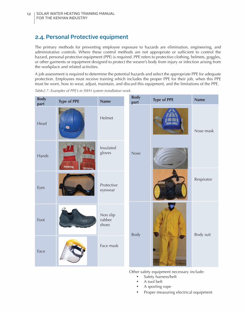
2.4. Personal Protective equipmentThe primary methods for preventing employee exposure to hazards are elimination, engineering, and administrative controls. Where these control methods are not appropriate or sufficient to control the hazard, personal protective equipment (PPE) is required. PPE refers to protective clothing, helmets, goggles, or other garments or equipment designed to protect the wearer’s body from injury or infection arising from the workplace and related activities.
A job assessment is required to determine the potential hazards and select the appropriate PPE for adequate protection. Employees must receive training which includes the proper PPE for their job, when this PPE must be worn, how to wear, adjust, maintain, and discard this equipment, and the limitations of the PPE.
Table2.7: Examples of PPE’s in SWH system installation work.
Body part
Type of PPE Name
HeadHelmet
Hands
Insulated gloves
EyesProtective eyewear
FootNon slip rubber shoes
FaceFace mask
Body part
Type of PPE Name
Nose
Nose mask
Respirator
Body Body suit
Other safety equipment necessary include:• Safety harness/belt• A tool belt• A sporting rope• Proper measuring electrical equipment

SOLAR WATER HEATING TRAINING MANUAL FOR THE KENYAN INDUSTRY
13
2.5. Site safety resourcesBelow is a list of resources that should be within the site.
• A safety plan
• Safety signs
• A ladder or scaffolding with secure base
• Hoisting equipment
• First aid kit
The system installers should ensure electrical safety such as earthing, proper termination of cables and insulation is done before commencing any job.
There are necessary arrangements that are required on site to ensure there is maximum protection of the workers. These are
a) Insurance cover that covers all risks and accidents that may arise at the workplace. The workers are also encouraged to secure personal accident cover through various insurance providers.
b) First Aid – This is a requirement by OSHA, 2007. It is therefore important to have a first aid kit and trained personnel on site.
c) Securing the site -There is need to secure the site to mitigate risks to the employees, the public or other people nearby from being exposed to various hazards. This may include:
• Cordoning off the area
• Proper signage
d) Avoiding lone working. It is good practice to always work at least in pairs under whatever situation.
NB: The site should be left clean and habitable before exit

SOLAR WATER HEATING TRAINING MANUAL FOR THE KENYAN INDUSTRY
14
3.1. The solar resourceSolar energy is simply energy from the sun. The energy comes in form of light or heat. The sun is composed of gases that react with each other releasing enormous amounts of heat or technically called electromagnetic radiation that lights up the entire outer space. The temperature at the surface of the sun is in the range of 5480 – 6000oC.
However despite this high temperature and energy, only a small fraction reaches the earth’s surface. One of the reasons for this is the distance between the sun and earth which is about 149.6 million kilometres as shown in Figure 3.2. As a matter of fact, the amount of solar radiation intensity which reaches the earth’s atmosphere is about 1.367kW/m2, referred to as the solar constant.
Figure 3.2.: Distance between the sun and earth (D= diameter).
On reaching the earth’s atmosphere, the strength of the rays reduces further due to other factors. The movement of the earth around the sun and the earth’s rotation on its own axis results in further losses. Other factors that play a very big role in reducing this energy within the earth’s atmosphere include clouds, air molecules, water vapour, dust particles, smoke and other elements. All these elements absorb, scatter or reflect the energy coming from the sun further reducing what reaches the earth’s surface as shown in Figure 3.3.
Figure 3.3: Illustration of how the solar radiation is reduced before reaching the earths surface.
3. Solar Science And Technology

SOLAR WATER HEATING TRAINING MANUAL FOR THE KENYAN INDUSTRY
15
Therefore, depending on the location, the earth’s movements and the elements in the atmosphere, the intensity or strength of solar energy will be different. The rays of the sun that reach the earth’s surface without inference are termed as direct radiation while those that reach the earth’s surface after being reflected or scattered by atmospheric elements are called diffuse radiation. Both of these are important and collectively form the total radiation or what is called global radiation. When the sky is clear and the sun is directly overhead (zenith), the direct radiation is around 85% of the total insolation striking the ground and diffuse radiation is about 15%. As the sun goes further away from the zenith, the percentage of diffuse radiation keeps going up and reaches 40% when the sun is 10° above the horizon.
Atmospheric elements like clouds and pollution also increase the percentage of diffuse radiation, the larger the percentage of diffuse radiation, the less the total insolation. Direct radiation is more important for solar water heating as these rays are able to penetrate the collector surface with ease. Focusing collectors that use mirrors to concentrate sunlight only reflect the direct component, whereas flat plate, non-focusing collectors can also harvest the diffuse radiation.
Figure 3.4: Direct and Diffuse radiation
3.2. Solar radiation in KenyaThe strength of solar intensity is measured in kW/m2 and varies from time to time. The daily energy in kWh/m2/day reaching a particular location is determined by measuring the intensity over a period of time. When the weather at any location is cloudy or rainy, the intensity and the energy received in a day will be less compared to that of a sunny day.
Kenya’s geographical location across the equator gives it a unique advantage as the natural sun-earth movements do not significantly affect the total solar energy that reaches the surface all year round. However, other weather parameters such as clouds and mist cause the notable differences. Generally, the country receives between 4 and 6KWh/m2/day of solar energy. Table 3.1 gives some monthly averages of selected towns and their respective annual averages just to show the potential at a glance.
Source: Twidell and Tony
Figure 3.1: Image of the sun’s surface

SOLAR WATER HEATING TRAINING MANUAL FOR THE KENYAN INDUSTRY
16
Table 3.1 Monthly solar insolation for selected towns in Kenya
Solar insolation for selected towns in Kenya (kWh/m2/day)
Town J F M A M J J A S O N D Av
Nairobi 5.76 6.34 5.97 5.26 5.01 4.54 4.40 4.65 5.61 5.33 4.69 5.20 5.23
Nakuru 6.19 6.67 6.47 5.92 5.95 5.61 5.49 5.85 6.58 6.07 5.43 5.76 6.00
Eldoret 5.94 6.37 6.21 5.70 5.60 5.21 5.10 5.45 6.16 5.82 5.40 5.66 5.72
Kisumu 5.92 6.33 6.27 5.64 5.45 5.06 4.91 5.11 5.91 5.73 5.42 5.76 5.63
Homa Bay 6.20 6.55 6.57 6.06 5.90 5.67 5.74 6.11 6.47 6.20 5.92 6.13 6.13
Mombasa 6.23 6.54 6.48 5.64 4.84 4.75 4.90 5.65 6.35 6.45 6.37 6.20 5.87
Mandera 6.23 6.67 6.62 5.75 5.53 5.06 5.02 5.59 6.17 5.49 5.35 5.81 5.77
Max values in orange and min values in light green. Adopted from: NASA Langley Research Center Atmospheric Science Data Center Surface meteorological and Solar Energy web portal
3.3. The path of the sun in KenyaAs earlier mentioned, the position of the sun will always vary due to the earth’s rotation on its axis (day/night) and its revolution around the sun (seasons). The actual position of the sun with respect to any location on the earth’s surface is specified using two angles namely;
• Altitude (γ) the angle between the sun and the horizon (in degrees)
• Azimuth (α) the angle between north and the sun’s position (in a clockwise direction from north). Similar to using a compass where the direction being faced is measured as a number of degrees from north.
As such, the altitude and azimuth of the sun constantly changes throughout the day (earth rotates on its axis) and year (revolving around the sun - seasonal variation).
N
S
W
E
Altitudeγ
Azimuthα
Zenith
Sun
Figure 3.5: Altitude and azimuth angles.

SOLAR WATER HEATING TRAINING MANUAL FOR THE KENYAN INDUSTRY
17
Table 3.2 shows both the altitude and azimuth angles for Nairobi in June and December while figure 3.6 further illustrates typical sun paths in Kenya.
Table 3.2: Altitude and Azimuth angles for Nairobi in June and December
June (Average) December (Average)
Solar noon 12.33pm 12.26pm
Time Azimuth Altitude Azimuth Altitude
7 am 66.6o 5.88o 112o 8.50o
8 am 64.9o 19.5o 114o 22.2o
9 am 61.2o 32.9o 117o 35.7o
10 am 54.2o 45.6o 124o 48.6o
11 am 41.2o 56.8o 137o 60.0o
12 noon 17.3o 64.4o 164o 67.5o
1 pm 344o 64.7o 200o 66.8o
2 pm 320o 57.6o 224o 58.4o
3 pm 306o 46.5o 237o 46.7o
4 pm 299o 33.9o 243o 33.6o
5 pm 295o 20.5o 246o 20.1o
6 pm 293o 6.91o 247o 6.36o
Adopted from: NASA Langley Research Center Atmospheric Science Data Center Surface meteorological and Solar Energy web portal
Figure 3.6: Typical 3-D appearance of Sun Path in Kenya.

SOLAR WATER HEATING TRAINING MANUAL FOR THE KENYAN INDUSTRY
18
Figure 3.7 also gives an aerial view of the movement of the sun across some towns in Kenya. The yellow band shows how the position of the sun varies over the year from morning to evening with the extremes (green and blue curves) showing the position and the path of the sun in June 21 and December 23 respectively.
Mombasa, Kisumu, Mandera, & Kitale
Green = June solstice, Orange = sun path on said date, Blue = Dec solstice &Yellow band = Annual variation
Figure 3.7: Sun’s path over sampled towns in Kenya
3.4. Orientation and InclinationThe energy from the sun is constantly changing due to the conditions under which it is received on the earth’s surface. As seen from the previous discussions, there are quite a number of parameters that affect the reception of the sun on a particular surface. Due to these changes, it is desirable to optimise the reception throughout the year by way of orientation and inclination of the receiving surface.
3.4.1. OrientationOrientation should ensure that the surface receives sunlight all the day from morning to evening. The sun moves from east to west every day and as such, it is ideal to ensure that collectors are oriented to the north-south direction.
3.4.2. Inclination and tilt angleThe position of the sun on the other hand varies seasonally. In the northern hemisphere the sun is more direct or closer around the month of June (June solstice) while in the southern hemisphere around December (December solstice) as depicted in figure 3.6. Inclination attempts to strike a balance between the high insolation months and the low insolation months. In other words, the reception during the high insolation months is reduced and that of the low insolation months is increased.
In figure 3.8, the curve in black shows the insolation levels on a horizontal plane. When the surface is tilted to 15o, the insolation curve in blue appears balanced as compared to the former one.
In Kenya, based on the above figure and values in table 3.1, solar collectors should be oriented to face north. This is because the insolation in June-July is lowest as compared to December-January. For roof-top mounts where the roof may not be facing true North, the collector area can be increased to compensate for this deviation (refer to chapter 9 for over-sizing factors).
The second purpose of inclination is to allow for self-cleaning of collectors. Irrespective of the solar reception, collectors should be tilted to a minimum of 10-15° to allow for self-cleaning. Based on the two aspects, the recommended tilt angle for collectors in Kenya is 15-20°, any angle steeper than 20o requires an increase in collector area too.

SOLAR WATER HEATING TRAINING MANUAL FOR THE KENYAN INDUSTRY
19
3.5. Local Climate effects and man-made features
3.5.1. The Effects of CloudsThe effects of clouds on the solar radiation received on the Earth’s surface are complex. Despite the reflection and the scattering aspect earlier mentioned, clouds are usually in motion and vary both in intensity and amounts from day to day. If there is a cloud between the sun and the point of focus, then the direct solar radiation is weakened or eliminated. Diffuse solar radiation, on the other hand, may be greater or less in the presence of cloud than under a clear sky, depending on the type and amount of the clouds. Thin layers of cloud, and scattered clouds reflecting sunlight, increase the diffuse solar irradiation; thick layers of cloud reduce diffuse solar radiation.
Global solar radiation is usually reduced by clouds, but if the sun is shining in a clear part of the sky and there are brightly illuminated clouds nearby, then global solar radiation may be greater than it would be under a completely clear sky.
3.5.2. RainsRains pose both negative and positive effects on the reception of solar radiation. When it rains, the sky is usually cloudy and therefore the sun is obstructed. Rains on the other hand help in cleaning up the atmosphere making it free of dust particles and other elements. It also helps in the cleaning of the receiving collector surface by removing other obstructing materials.
3.5.3. Other obstaclesBesides clouds; buildings, trees and birds also interfere with the reception of solar radiation on a surface. Adjacent structures such as high buildings can greatly affect the incident solar radiation at a site. The structures block the direct radiation from the sun and cast shadows on the collector. The movement of the shadow varies seasonally. Therefore it may be difficult to address the problem for a particular location.
Trees pose similar problems as buildings. However, it becomes even more difficult to plan for them since one may not entirely control when or where to plant them. Trees also grow with time and some may not seem to pose any obstruction but later on become a problem. Birds on the other hand usually make solar collectors a resting and nesting place. Besides dust, birds’ droppings and nests block the collector surface from receiving the available solar radiation.
Figure 3.8: Effect of tilting

SOLAR WATER HEATING TRAINING MANUAL FOR THE KENYAN INDUSTRY
20
3.5.4. Soiling and cleaning of arraysMost people rely on rain to keep the array clean; without any regularly scheduled cleaning regimen. Improvement in yield due to cleaning are reported as 6% in one study and 7.4% in another. However, this is highly dependent on local conditions and local sources of dirt. Cleaning may be on a defined interval or “condition based,” and the impact of soiling can be assessed to trigger a cleaning. Soiling and resulting cleaning regimen depend on local sources of dirt. Sources of soiling that may indicate the need for a cleaning regimen include:
• Agricultural dust: cleaning can be scheduled following ploughing.
• Construction dust: cleaning can be scheduled after completion of nearby construction
• Pollen: schedule cleaning after end of pollen season.
• Bird Populations: Reduce open cracks between panels where birds can build nests; use plastic “birdslides” to change flat surfaces to steep-sloped surfaces; use Bird Netting to seal areas under the panels down to the roof completely around the array; install Bird Spikes along the top edge of the array to prevent roosting; use plastic owl or falcon with swivel head to scare off birds; Schedule rooftop activities and removal of nests according to nesting season timing. Birds are creatures of habit and their behaviour can be changed over time to avoid your roof.
• Diesel Soot: present in cities and concentrations such as bus depot and may require frequent cleaning.
• Industrial Sources: Processes such as cooking or manufacturing can be sources of array soiling. This can be identified by testing samples of the dirt.
Clean solar collectors with plain water or mild dishwashing detergent, similar to that used for window glass. Do not use high-pressure water, brushes, and any types of solvents, abrasives, or harsh detergents.
3.6. Basic Heat Transfer Mechanisms
3.6.1. ConductionConduction is the transfer of heat by the movement of particles that are in contact with each other caused by a temperature difference between them. Metals especially copper are good examples of conductors. For this exchange to take place, the molecules must get into contact with each other. If one heats one end of a copper rod, heat spreads very fast to the entire length of the rod and it can be felt easily from the other end (See figure 3.9). Conduction is best in solids but also occurs in liquids and gases or a combination of any of the two. Conduction cannot take place in vacuum.
Sourceofheat
Support
Wax
Pins
Metalrod
Figure 3.9: Heat transfer through conduction

SOLAR WATER HEATING TRAINING MANUAL FOR THE KENYAN INDUSTRY
21
3.6.2. ConvectionConvection is heat transfer by mass motion of a fluid such as air or water. The heated fluid moves away from the source of heat, carrying energy with it. Convection above a hot surface occurs because hot fluids expand, become less dense, and rise.
Figure 3.10: Convection heat transfer in liquids
3.6.2.1. Free convectionIn free convection (also natural convection or thermosiphon) the movement is caused by the heat flow itself. When a fluid is in contact with the hot surfaces, initially the fluid absorbs energy by conduction from the hot surface. The molecules of the fluid get energised and start moving faster and so the fluid density decreases as the volume expands. The heated portion then rises through the unheated fluid, thereby transporting heat physically upwards.
3.6.2.2. Forced convectionIn forced convection the fluid is actively moved over the heating surface by an external force such as a pump. The movement occurs independently of the heat transfer (i.e. is not a function of the local temperature gradients).
3.6.3. RadiationRadiation is the transfer of heat by means of electromagnetic waves. To radiate means to send out or spread from a central location. Whether it is light, sound, waves, rays, flower petals, or pain, if something radiates then it spreads outward from an origin. The transfer of heat by radiation involves the carrying of energy from an origin to the space surrounding it. That is why we are able to feel the heat from a fire place or an oven even from a distance. The energy is carried by electromagnetic waves and does not involve the movement or the interaction of matter. The solar water heating collector receives electromagnetic radiation from the sun which it converts to heat energy.
Figure 3.11: Radiation heat transfer from fire and the sun

SOLAR WATER HEATING TRAINING MANUAL FOR THE KENYAN INDUSTRY
22
3.7. Water Heating Techniques using solar energyThe three heat transfer mechanisms play a very big role in heating water for various applications. Solar collectors are the main converters used to facilitate this transfer of heat from the sun to water. In principle, collectors are categorised into three groups mainly based on the temperatures of the required hot water.
These categories are:
i. Low temperature collectors
a. Unglazed mats (Swimming pool collectors)
b. Perforated plates (Ventilation air preheating)
ii. Medium temperature collectors
a. Glazed and insulated collectors (Domestic water, space heating, commercial and industrial process heating)
iii. High temperature collectors
a. Evacuated tubes (domestic and industrial process heating)
b. Concentrating collectors (Electricity generation)
Low temperature collectors are used for space heating, drying or warming water mainly in swimming pools (40-60oC). Medium temperature collectors are used in heating water for domestic use or provision of medium temperature process heat (70-90oC). High temperature collectors on the other hand provide high temperature process heat and also provide steam used in electricity generation (90-400oC).
In the context of this manual, the focus is more on medium temperature collectors and therefore, flat plate collectors and evacuated tube collectors dominate in subsequent discussions.
Figure 3.12: Example of collectors for various applications

SOLAR WATER HEATING TRAINING MANUAL FOR THE KENYAN INDUSTRY
23
3.8. Application of heat transfer mechanisms to the various types of solar water heaters
3.8.1. Passive and Direct solar water heating system (thermosiphon)In figure 3.13, solar radiation heats up the collector tubes through radiative heat transfer, the copper tubes of the collector transfer heat to the fluid through conduction and the heated water rises up through convection. Natural circulation within the SWH system takes place due to convention and depends on the tilt angle (15° to 45°). Hot water is directly used by consumer.
Figure 3.13: Illustration of a direct SWH system
3.8.2. Passive and Indirect solar water heating system (also thermosiphon)The passive and indirect SWH system works in a similar way to the passive and direct system. However, as shown in figure 3.14, the water or fluid that runs through the collector and the inner tank (E) is different from what gets to the user. The inner tank and the collector form a closed loop. Heat transfer from the inner tank to outer tank is through both conduction and convection.
Figure 3.14: Illustration of an indirect SWH system
A = Cold water in from the mains
B = Cold water flows to the bottom
C = Hot water rises up to the top of collector
D = Hot water rises & accumulates in the top of the tank
E = Hot water for use.
A= Sacrificial anode rod
B = Collectors
C = Insulation casing
D = Outer tank
E = Inner tank
1 = Cold water in
2 = Cold fluid flowing into the collector
3 = Hot fluid out of collector
4 = Hot water heated up by the inner tank
5 = Hot water out
SOLAR WATER HEATING TRAINING MANUAL FOR THE KENYAN INDUSTRY
24
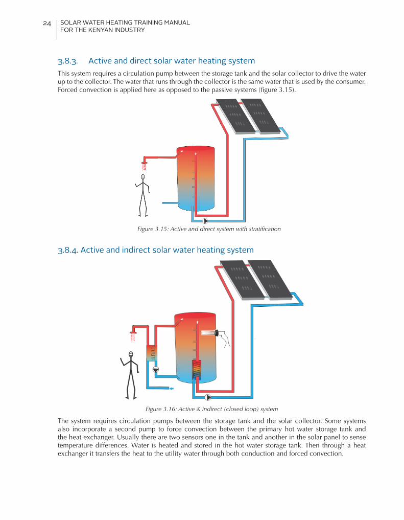
3.8.3. Active and direct solar water heating systemThis system requires a circulation pump between the storage tank and the solar collector to drive the water up to the collector. The water that runs through the collector is the same water that is used by the consumer. Forced convection is applied here as opposed to the passive systems (figure 3.15).
Figure 3.15: Active and direct system with stratification
3.8.4. Active and indirect solar water heating system
Figure 3.16: Active & indirect (closed loop) system
The system requires circulation pumps between the storage tank and the solar collector. Some systems also incorporate a second pump to force convection between the primary hot water storage tank and the heat exchanger. Usually there are two sensors one in the tank and another in the solar panel to sense temperature differences. Water is heated and stored in the hot water storage tank. Then through a heat exchanger it transfers the heat to the utility water through both conduction and forced convection.

SOLAR WATER HEATING TRAINING MANUAL FOR THE KENYAN INDUSTRY
25
3.9. Other important concepts used in solar water heating technology3.9.1. Water stratification in the tank and hot and cold plumbing connectionsStratification is the formation into layers of water at different temperatures. The difference in density of cold and hot water leads to stratification. Therefore hot water remains on top of the tank and hot plumbing connections should be at the top while cold plumbing connections should be at the bottom. If one intends to have uniform temperature in the storage tank, the hot pipe plumbing should be closer to the bottom. If one wants to have laminar or stratified layers, then the hot pipe plumbing should be on the upper part of the tank. Hot water outlet should always be on the top of the tank to draw the hottest volume. General plumbing codes should be observed.
Figure 3.17: Using coloured water to show how stratification works. A) pipe with perforations in the tank; B) hot water comes out through different holes depending on its temperature; C) laminars of coloured water distribute themselves depending on temperature
Heat traps in hot water pipesHeat traps are valves or loops of pipe installed on the cold water inlet and hot water outlet pipes on water heaters. The heat traps allow cold water to flow into the water heater tank, but prevent unwanted convection and heated water to flow out of the tank. They are an effective way to prevent cooling of hot water in water heaters by thermosiphoning the hot water to a higher elevated portion of the piping system. Thermosiphoning is based on natural convection. Hot water rises and is then displaced by cold water beneath it. The heat trap stops this process, thus keeping the hot water inside the insulated storage tank.
When correctly installed, a heat trap gives the valve an opportunity to cool down when it´s not on duty between occasions when hot water is trapped.
Figure 3.18: Schema of heat trap and thermostatic mixing valve
SOLAR WATER HEATING TRAINING MANUAL FOR THE KENYAN INDUSTRY
26
3.9.3. Thermostatic mixing valveMainly the valve mixes both hot and cold water to get output water at a set temperature that is conducive to the end user as well as prevent melting of plastic pipes. This is more so for houses with single pipe plumbing that were not designed with SWH in consideration. In such a situation, the hot water ends up being used in all household applications.
3.9.4. The minimum TemperatureIt is recommended that hot water supply from a solar water heating system be at a minimum temperature of 60oC. This is to prevent creating a favourable environment for bacteria that are found in water (legionnaires) which survive below 60oC. Legionnaires thrive at water temperatures between 25 and 42°C with an optimum temperature of 35°C. Hot-water tanks, cooling towers, and evaporative condensers of large air-conditioning systems, such as those commonly found in hotels and large office buildings are common sources where temperatures allow the bacteria to thrive best.
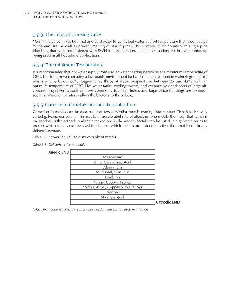
3.9.5. Corrosion of metals and anodic protectionCorrosion in metals can be as a result of two dissimilar metals coming into contact. This is technically called galvanic corrosion. This results in accelerated rate of attack on one metal. The metal that remains un-attacked is the cathode and the attacked one is the anode. Metals can be listed in a galvanic series to predict which metals can be used together or which metal can protect the other (be ‘sacrificed’) in any different scenario.
Table 3.1 shows the galvanic series table of metals.
Table 3.1: Galvanic series of metals
Anodic ENDMagnesium
Zinc, Galvanized steelAluminium
Mild steel, Cast ironLead, Tin
*Brass, Copper, Bronze*Nickel-silver, Copper-Nickel alloys
*MonelStainless steel
Cathodic END
*Have low tendency to show galvanic protection and can be used with others
SOLAR WATER HEATING TRAINING MANUAL FOR THE KENYAN INDUSTRY
27
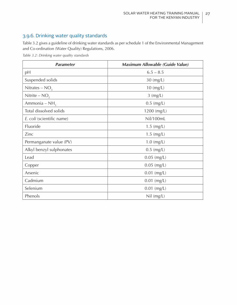
3.9.6. Drinking water quality standardsTable 3.2 gives a guideline of drinking water standards as per schedule 1 of the Environmental Management and Co-ordination (Water Quality) Regulations, 2006.
Table 3.2: Drinking water quality standards
Parameter Maximum Allowable (Guide Value)
pH 6.5 – 8.5
Suspended solids 30 (mg/L)
Nitrates – NO3 10 (mg/L)
Nitrite – NO2 3 (mg/L)
Ammonia – NH3 0.5 (mg/L)
Total dissolved solids 1200 (mg/L)
E. coli (scientific name) Nil/100mL
Fluoride 1.5 (mg/L)
Zinc 1.5 (mg/L)
Permanganate value (PV) 1.0 (mg/L)
Alkyl benzyl sulphonates 0.5 (mg/L)
Lead 0.05 (mg/L)
Copper 0.05 (mg/L)
Arsenic 0.01 (mg/L)
Cadmium 0.01 (mg/L)
Selenium 0.01 (mg/L)
Phenols Nil (mg/L)

SOLAR WATER HEATING TRAINING MANUAL FOR THE KENYAN INDUSTRY
28
4. Solar Water Heating ComponentsAs discussed earlier, there are quite a number of different types of solar water heating systems and depending on the type; several components are connected to make up a complete system. Despite the differences, all systems have similarities and only vary slightly.
Key components include:• Solar collectors• Mounting structures• Hot water tanks• Backup systems• Valves• Heat exchangers• Heat transfer fluids• Pipes• Pumps • Controllers• Expansion tanks
4.1. CollectorsA solar water heating collector captures or absorbs heat from the sun in form of electromagnetic radiation and transfers that heat to the water. The collector is the main device in the system, without which the system would not deliver hot water.
As already observed in the introductory section, solar collectors can further be broadly classified into two main types; non-concentrating and concentrating. Explanations here only focus on the non-concentrating types and more so the medium temperature types i.e. flat plate and evacuated tube collectors.
4.1.1. Flat plate collectors
The flat plate collector is the most commonly used solar collector around the world. Although there are a number of variations in the design of the flat plate collector, a typical flat-plate collector is usually a metal box with a glass or plastic cover (called glazing) on top and a dark-coloured absorber plate with embodied fins (pipes) enclosed within. The sides and the bottom of the collector are usually insulated to minimize heat loss.
Individual components of the collector consist of:
• Glazing: Toughened glass (glazing) that protects the absorber from the outside environment while allowing over 90% of sunlight through. It also prevents heat loss in form of longer infrared waves from leaving the housing.
• Absorber plate: A thin sheet made of copper or aluminium coated with a highly selective material that is extremely efficient at absorbing sunlight and converting it into usable heat. The copper or aluminium sheet is ultrasonically welded to the copper riser pipes sometimes called fins.
• Riser & Header Pipe: There are both top and bottom headers connected to the riser pipes. The risers are brazed together to form a heat exchanger that the system’s heat transfer fluid circulates through. Solar energy incident on the absorber plate is transferred to the fluid flowing through the riser tubes. Cool water enters from the bottom header and warmed water exits through the top header. The risers should be good conductors and have a large surface area.

SOLAR WATER HEATING TRAINING MANUAL FOR THE KENYAN INDUSTRY
29
• Insulation: The insulation helps reduce heat loss from the sides and the back of the collector. The material should be light in weight and low thermal conductivity. e.g. ultra-light weight melamine foam or fibre glass, Collector frame: The outer framework of the collector is made of a light and strong material and designed in such a way that it is easy to mount. E.g. aluminium alloy
• Back Sheet: it seals the back of the collector and adds to the rigidity of the collector while offering protection from weather elements. It can be made from aluminium alloy or galvanized iron sheets etc.
The temperature range of flat plate collectors is generally 30 - 80°C.
Figure 4.1 shows the parts of a flat plate collector.
Figure 4.1: Parts of a flat plate collector
Figure 4.2 shows a cross section of a flat plate collector.
Figure 4.2: Cross-section of flat plate collector showing absorber, aperture and gross area
4.1.2. Evacuated tube collectorsThe evacuated tube collectors are made of a series of glass tubes mounted in rows and plugged into a manifold box through which the heat transfer liquid (water or water/glycol) flows. Toxic fluids such as ethylene glycol should not be used in potable water heating systems - only non-toxic propylene glycol may be used. Inside each tube there is an absorber. The absorber is located inside a double glass tube with a vacuum between the two tubes. The inner glass tube has a selective surface facing outward to absorb the sun’s energy. The absorber contains copper tubes or passageways through which the heat transfer fluid flows allowing the heat to be transported away from the absorber.
The loss of heat from the absorber by natural convection is eliminated by the vacuum and, as a result, high operating fluid temperatures of up to 120oC can be achieved. The possibility of higher temperatures is of particular importance for solar industrial process heating application because it increases the number of applications where solar energy can be used.
Source: Master plumbers et al.
Source: Master plumbers et al.

SOLAR WATER HEATING TRAINING MANUAL FOR THE KENYAN INDUSTRY
30
There are two common types of evacuated tube collectors; heat pipe and U-tube.
4.1.2.1. Evacuated heat pipe collectors A heat pipe evacuated tube collector uses heat pipes to transfer the collected solar heat from the tube into the flowing fluid in the manifold. Heat pipes are made up of copper tubes which contain a very small amount of water in a partial vacuum. The heat pipe is encased in the inner glass tube. When the heat pipe is heated, the small amounts of water inside vaporise and rise to the top of the heat pipe into the heat exchanger in the manifold. The flowing cold water is heated through the manifold and at the same time cools the vapour inside the heat pipe where it condenses and falls to the bottom of the heat pipe. Figure 4.3 shows a schematic of a heat pipe evacuated tube. An inclination of 20° should be permitted to function.
Figure 4.3: Evacuated heat pipe
4.1.2.2. Evacuated U-tube collectors As opposed to the evacuated heat pipe type, evacuated U-tube collectors allow cold water to be heated as it flows through a ‘U’ shaped copper pipe inside the glass tubes and exits as hot water as shown in figure 4.4.
Figure 4.4: Evacuated U tube
Source: Master plumbers et al.
Source: Master plumbers et al.
SOLAR WATER HEATING TRAINING MANUAL FOR THE KENYAN INDUSTRY
31
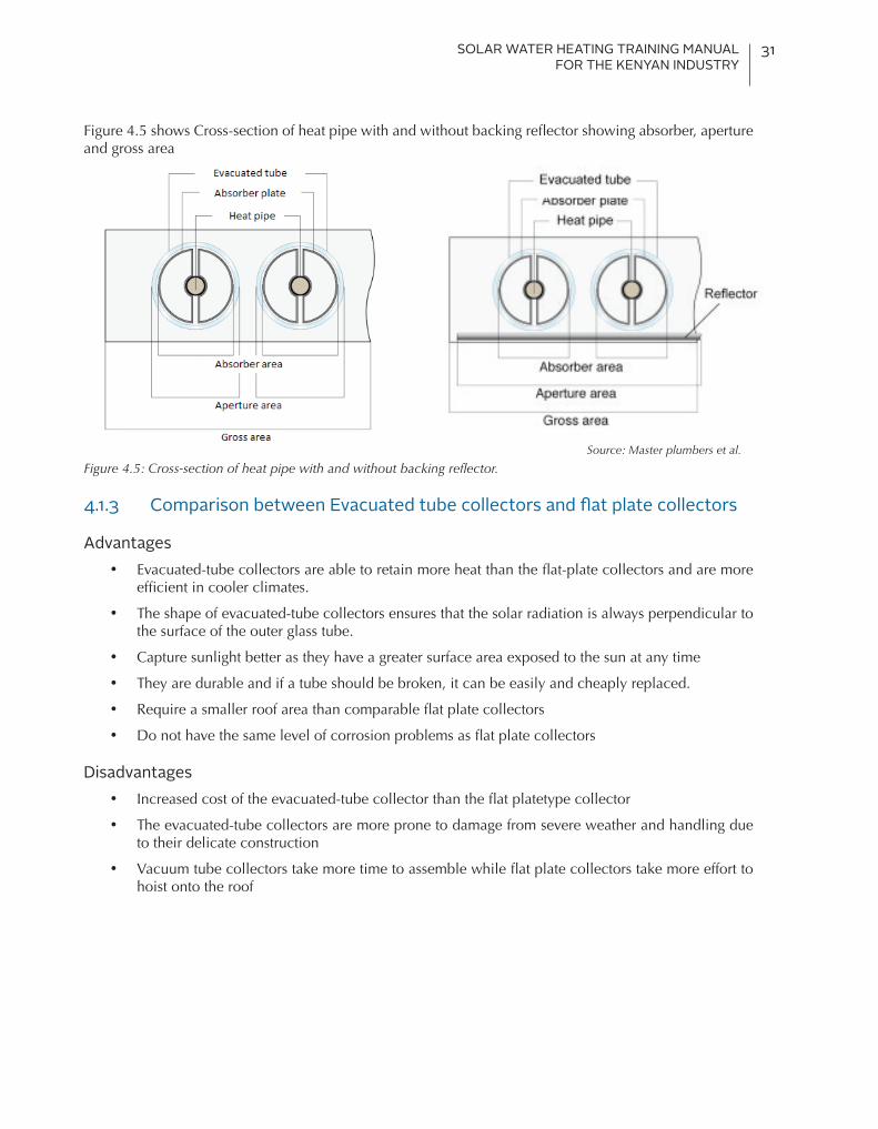
Figure 4.5 shows Cross-section of heat pipe with and without backing reflector showing absorber, aperture and gross area
Figure 4.5: Cross-section of heat pipe with and without backing reflector.
4.1.3 Comparison between Evacuated tube collectors and flat plate collectors
Advantages• Evacuated-tube collectors are able to retain more heat than the flat-plate collectors and are more
efficient in cooler climates.
• The shape of evacuated-tube collectors ensures that the solar radiation is always perpendicular to the surface of the outer glass tube.
• Capture sunlight better as they have a greater surface area exposed to the sun at any time
• They are durable and if a tube should be broken, it can be easily and cheaply replaced.
• Require a smaller roof area than comparable flat plate collectors
• Do not have the same level of corrosion problems as flat plate collectors
Disadvantages• Increased cost of the evacuated-tube collector than the flat platetype collector
• The evacuated-tube collectors are more prone to damage from severe weather and handling due to their delicate construction
• Vacuum tube collectors take more time to assemble while flat plate collectors take more effort to hoist onto the roof
Source: Master plumbers et al.

SOLAR WATER HEATING TRAINING MANUAL FOR THE KENYAN INDUSTRY
32
Figure 4.6: Absorber plate (with covering to protect coating), complete flat plate collector, evacuated heat pipe for active systems and Evacuated heat pipe for passive system - by Steelstone.

SOLAR WATER HEATING TRAINING MANUAL FOR THE KENYAN INDUSTRY
33
4.2. Mounts and mounting structuresCollectors may be either roof mounted or ground mounted. They must be firmly mounted to secure them against any external interference. Mounted collectors are not only exposed to the sun but also to other weather conditions like the wind forces, rain, snow and ultra violet rays. Winds and thermal expansion and contraction may cause installed bolts and roof seals to loosen over time if not well done.
The most common arrangement is where the collector is above and parallel to a metal or tiled roof. The minimum tilt for flat plate collectors required for effective cleaning by rainwater and for thermosiphon effect is 15° while for evacuated tubes 20° to ensure reliable working of the heat pipe to transfer heat to the manifold.
For all roof mounts, special consideration is needed and includes,
• Collectors should never be mounted near the edge or ridge of a roof where the wind load may be unusually high.
• On a pitched roof a collector requires at least four mounting points. Extra timber bracing is usually required inside timber roofs to spread the load.
• For new roofs, purposely made structural mounting points can be provided in advance
Mounting collectors on the roof can be done in up to four ways;
i. Rack Mounting - This method is used for flat roofs or roofs with inappropriate pitch. The collectors are mounted at the required tilt angle on a structural frame. The structural connection between the collector and the frame and between the frame and the building or site must be adequate to resist the maximum potential loads
ii. Standoff mounting - Standoff elevate the collector from the finished roof surface. They allow air and rain water to pass under the collector and minimize problems of water retention and growth of moulds or fungus. They are sometimes used to support collectors at slightly different tilt angles from that of the roof pitch angle. The standoff brackets must be strong enough to support the collector filled with water. This is the most common mounting method used.
iii. Direct Mounting - collectors are mounted directly on the roof surface. They are mounted on a waterproof membrane covering the roof. Then the finished roof surface, the collector and its structural attachments and waterproof flashing are built up around the collector. A water proof seal must be maintained between the collector and the roof to avoid leakage, moulds and rotting of timber.
Fig. 4.7: Roof mounting structure for flat roofs and an example of a rack mounting on tile roof to adjust pitch

SOLAR WATER HEATING TRAINING MANUAL FOR THE KENYAN INDUSTRY
34
iv. Integral Mounting - the collector is mounted within the roof construction itself. The collector is attached to and supported by the structural framing members. The top of the collector serves as the finished roof surface. Weather proofing is crucial to avoid leakage, moulds and damage by rain water. The roofing materials and collectors expand and contract at different rates and therefore the risk of leakage is high. Only collectors designed by the manufacturer for integration into the roof should be installed as the moisture/water barrier of the roof.
v. Ground mounting- ground mounting is an alternative to roof mounting where the collector is mounted at the ground level. Similar to the Rack mounts, ground mounts are mounted at the required tilt angle with the stands being firmly anchored into the ground. A concrete platform can be prepared to affix the structure on it or some holes may be dug and the poles sunk and fixed into the holes using concrete mixture. The lower edge of the collector usually rises 0.5 metres above the ground to avoid shading by growing vegetation.
4.3. Hot water storage tanksThe energy absorbed by the collector and transferred to the flowing water may not be required during periods of generation. This hot water requires storage for later use by the consumer. Domestic hot water tanks store the hot water harmonising supply and demand time variations. Thermal stratification is critical to ensuring the availability of thermal energy. Stainless steel walled tanks significantly reduce heat degradation compared to copper.
4.3.1. Types of storage tanksVariations in hot water tank types are basically due to the material used to make them. There are various types of tanks but only two are common in the Kenyan market namely mild steel and stainless steel tanks:
Mild steel - These are the most common tanks and are found in most standard hot water storage tank systems. They are typically lined with a spun glass polymer (often called vitreous enamel) which protects the inside of the tank from direct exposure to water. Unfortunately, this does not waterproof the whole interior of the tank and rusting eventually occurs. Due to the danger of corrosion, mild steel tanks incorporate a sacrificial anode.
Sacrificial anodes are typically made of magnesium with small percentages of manganese, aluminium or zinc (refer to table 3.1 discussed earlier). They may also be made magnesium or aluminium wrapped around a steel core wire. This rod will corrode instead of the steel tank. The tank is protected so long as there is still some metal on the rod. As soon as the rod disintegrates, any steel touching water begins to rust. Sacrificial anodes are replaced every 2-5 years (depending on the quality of water) to ensure the health of mild steel tanks. Forgetting to do so is still the number one cause of mild steel-tank failure.
Stainless steel- These tanks are designed to allow direct water exposure with no risk of corrosion and a sacrificial anode is not necessary. Stainless steel tanks are much more expensive than mild steel ones and the reason they are not as common. The warranty for stainless steel tanks is usually twice as long there is a much smaller risk of tank failure.
Galvanized Iron tanks- These tanks are cheaper to manufacture but can become prone to rust as the zinc galvanizing may break down over time when used with hot water. Any welding joints should be re-galvanized after the welding process.
Enamel-lined tanks- These tanks are able to withstand corrosion from heat and poor quality water due to the enamel coating inside the tank. Long term expansion and contraction of the tank due to wide temperature changes however cause the enamel coating to crack making them prone to corrosion as well. This problem has to be overcome by using a sacrificial anode inside the tank.

SOLAR WATER HEATING TRAINING MANUAL FOR THE KENYAN INDUSTRY
35
4.3.2. The basic structure of the tankThere are two types designs for hot water storage tanks mainly based on the application but the structures are relatively the same. For passive systems, the storage tanks are placed horizontally while active systems usually have their tanks placed vertically. As such, pipe connection provisions in terms of positioning differ in the two systems.
Irrespective of the application however, hot water storage tanks come with the storage tank lined with insulation material (usually polyurethane) and an outer casing for protection of the insulation material. Appropriate perforations are made on the tank for all necessary connections. Indirect systems in addition, also do have an inner tank or coil that serves as the heat exchanger.
4.4. Boosting /backup heaters for SWHThe hot water output from the solar water heating system is purely dependent on the available solar insolation. Since the insolation varies daily and seasonally, sometimes the hot water requirements exceed what the system can supply. As such, solar hot water systems have a boosting or backup system that guarantees hot water supply when there is insufficient solar radiation and making sure that water is heated to a temperature above 60°C to inhibit the growth of the Legionella bacteria.
The backup or booster may be an integral part of the tank or integrated in the pipeline away from the tank. The booster may be set to turn on automatically when the water temperature is below the thermostat setting and automatically turns off when the temperature reaches the thermostat setting. Alternatively it can be set up with a manual switch where the consumer can control the boosting of the system, depending on their needs. Timers can also be used to ensure the booster comes on only when the sun goes down to maximise the solar contribution. Boosters use an alternative source of energy, such as electricity, gas or even firewood, to heat the water.
Figure 4.9: Electric backup heater
Other alternatives for backup heating systems include; steam boilers, biogas, and low-heat geothermal steam, waste heat from other processes, other biomass heaters and heat pumps.
Figure 4.8: Tanks after fabrication, spray painting of jacket and complete tank – by Steelstone

SOLAR WATER HEATING TRAINING MANUAL FOR THE KENYAN INDUSTRY
36
4.5. ValvesHot water expands and will build up dangerous pressures in the tank and/or the collector loop if the solar collector is allowed to keep heating the water. As the pressure builds up, the boiling point of water increases and water in a solar collector could reach in excess of 100°C if unchecked. A number of valves are required for the system pipe work to prevent dangerous temperatures or pressure building up for safety reasons.
Valves can also serve the purpose of isolating parts of a system, expel and vent air from the system, maintain flow direction, prevent thermosiphon heat losses etc.
4.5.1. Temperature Pressure Relief ValveTPR valve allows water to be discharged through the device when conditions of excessive pressure, excessive temperature or both occur. When the valve opens, pressure from the tank, along with hot water, is released. As the water moves from the tank, the pressure drops and the exiting water is replaced with new much cooler water. This lowers the water temperature within the tank. When a safe level is reached, the safety valve shuts off.
The TPR valve usually starts functioning when tank pressures reach around 8 bar (8x10⁵ pascal). TPR valves should be installed within the top 6 inches of the tank. It comes in handy especially when the controller or the thermosiphon restrictor valve fails for active and thermosiphon systems respectively.
4.5.2. Pressure Reducing ValveA pressure-reducing valve is required on the cold inlet to the tank if mains inlet pressure is greater than 5bar pressure. There are two types of water pressure reducing valves, direct acting and pilot operated. Both use globe or angle style bodies with units made from ductile iron. Direct acting valves, the more popular type of a water pressure reducing valves, consist of globe-type bodies with a spring-loaded, heat-resistant diaphragm connected to the outlet of the valve that acts upon a spring. This spring holds a pre-set tension on the valve seat installed with a pressure equalizing mechanism for precise water pressure control.
Figure 4.10: TPR valve schema and photo.
Figure 4.11: Typical pressure relief valves – By Steelstone

SOLAR WATER HEATING TRAINING MANUAL FOR THE KENYAN INDUSTRY
37
4.5.3. Air Bleed ValveThe valve allows any trapped air within the system to escape preventing the formation of air pockets within the system. Air pockets prevent the flow of water in the system. The valves should be installed at the high point of any pipework and must be positioned vertically.
4.5.4. Non-Return ValveA non-return valve allows water to flow in only one direction. A non-return valve is fitted to ensure that water flows through a pipe in the right direction, where pressure conditions may otherwise cause reversed flow. This valve is installed on the cold water inlet to prevent the pressurized storage water tank back feeding water into the cold water inlet and, for an active system in the collector loop, to prevent reverse thermosiphon at night. There are different types of non-return valves, such as spring-loaded, swing type, and clapper type valves.
4.5.5. Isolation gate valvesIsolation gate valve separates or isolates the cold water inlet and various other sections of solar water heating system. For multiple system connections, individual systems can also be isolated for maintenance without affecting the entire system using isolation gate valves.
4.5.6. Thermosiphon Resistor (interruption) valveThis valve is used in thermosiphon systems. It is needed when the water present in the storage tank becomes so hot that the thermosiphon action ceases. The TRV placed in the cold flow pipe, greatly reduces flow of water through the collector when the desired temperature is reached, meaning excess heat is lost at the collector rather than overheating the tank.
4.5.7. Thermostatic mixing (or tempering) valveThe valve blends hot water with cold water to ensure constant, safe shower or bath outlet temperatures, preventing scalding. As earlier said, water needs to be stored at high temperatures to prevent breeding of Legionella. On the other hand, this temperature is relatively high for normal domestic use. The use of a thermostat, rather than a static mixing valve, provides increased safety against scalding, and increased user comfort, because the hot-water temperature remains constant. Where piping integrity may be compromised, the valve also prevents this risk.
Figure 4.13: Photo and schema of tempering valve
Figure 4.12: Air bleed valve – by Steelstone

SOLAR WATER HEATING TRAINING MANUAL FOR THE KENYAN INDUSTRY
38
4.6. SWH plumbing pipesSolar Water Heating systems can reach temperatures in excess of 100°C in the collector loop under conditions of stagnation. Therefore pipe work capable of handling such high temperatures should always be used. Standard copper or stainless steel pipes are best suited for such applications. However in Kenya, both CPVC (Chlorinated Polyvinyl Chloride) and PPR (Polypropylene Random copolymer) are used with SWH system. These are usually rated for 95°C and hence are not well suited for the collector loop. CPVC is UV resistant and can be used outdoors but PPR is not. Hence PPR requires UV-stabilized insulation material on all exposed pipe work. Both these materials can be used for hot water but the best practice would be to use them after a thermostatic mixing valve.
4.7. Insulation materialThermal losses in hot water pipes can account for more than 30% of water heating energy. It can be reduced by optimizing the length of water piping and proper insulation. Insulation material should be further protected by aluminium foiling, high density polythene or pipe cladding. Pipes measuring up to 25mm diameter require an insulation of 25mm thick while pipes with 25-75mm diameter require insulation of 50mm thick. Hot water pipes concealed in walls should also be insulated because there is a chance of walls developing cracks due to expansion of metallic pipes. Plastic insulation such as polystyrene or polyethylene should never be used due to their low operating temperatures. All exterior piping insulation should be protected from environmental and UV degradation by using special UV resistant coatings, paints or shielded wraps.
4.8. Heat exchangersHeat exchangers can either be internal or external to the storage tank. It is important to bear in mind that temperature stratification provides substantial operational performance benefits. For internal heat exchangers, correct integration of the tank and heat exchangers in a passive system is essential to allow for water stratification. The location of the heat exchanger and the flow rate in the collector loop determines the degree of thermal stratification.
Helical coil heat exchangers can be integrated in the collector loop or in the load side hot water storage. Plate type heat exchangers are commonly used externally with the fluid flowing in opposite direction.
Figure 4.15: Schema of internal helical coils and external plate heat exchanger
Figure 4.14: Fibre glass linings with aluminium foiling – by steelstone

SOLAR WATER HEATING TRAINING MANUAL FOR THE KENYAN INDUSTRY
39
Figure 4.16: Helical coil heat exchanger and interior of tube-in-tube exchanger – by Steelsotne
4.9. Heat transfer fluidsWhereas there are a variety of heat transfer fluids used in solar water heating systems, potable water is the most common working fluid especially for direct systems. Where temperatures may drop to freeze or near freeze, other fluids such as polypropylene glycol, ethylene glycol, hydrocarbon oils or synthetic oils (e.g. silicone) are used more so for indirect systems. Some fluids such as ethylene glycol are however toxic and utmost care is required.
4.10. PumpsA pressure pump may be required in areas where the mains pressure is below 3bar so as to provide reliable pressure to the water supply of the building. In Kenya however, most homes have accumulator tanks at a raised ground and this may not be necessary.
Circulation pumps on the other hand are required for active SWH systems. It’s required to push the water or glycol up into the solar collector from the storage tank. The pressure needed from the pump is not much as the collector loop is full of water/glycol. A non-return valve/heat trap is used in the collector loop to avoid heat loss through “reverse thermosiphon” action at night.
4.11. ControllersThey are used to control and regulate circulation pumps. The most common controller is the differential temperature controller which has two thermistors that are placed in the collector loop i.e., cold flow from the tank and the collector hot return outlet.
The controller basically turns the pump ON then the temperature difference between the collector and tank is around 5oC to 20oC and OFF when it is lower than 3oC to 5oC. It also turns the pump off when the tank reaches 70oC. The ‘OFF differential temperature is factory set and cannot be adjusted while the installer has the liberty of adjusting the ON differential depending on the system design. Systems with longer pipe runs require a slightly higher temperature difference while those with shorter pipe runs need a lower temperature difference. As a result, the collector loop can become very hot and pressurized. To avoid damage, a second TPR valve at the collector hot return outlet or an expansion tank is required.
Figure 4.17: Typical circulation pump – by Steelstone
Figure 4.18: Circulation pump controller – by Steelstone

SOLAR WATER HEATING TRAINING MANUAL FOR THE KENYAN INDUSTRY
40
PressureGaugeFlowMeter
TemperatureSensor
Pressure/TemperatureReliefValveAir Vent
Thermometer
PumpAirPurge
Flush&FillValves
strainer
ExpansionTank
Thermometer
Controller
TemperatureSensor
StorageTank
HotWaterOut
ElectricHeatingElement
Figure 4.19: Use of a controller and other components in a closed loop, active SWH system (Andy Walker, 2013)
4.12. Expansion tankTemperature pressure relief valves control the pressure within the tank through discharge. For indirect systems, the collector loop is usually closed and instead of losing the working fluid as with TPR, an expansion tank is more suitable.
Other components in the solar water heating system include tmers, pressure gauge, brass connectors etc.
Figure 4.20: Timer, pressure gauge, brass connectors – by Steelstone

SOLAR WATER HEATING TRAINING MANUAL FOR THE KENYAN INDUSTRY
41
5. Solar Water Heating System Design
Like any other renewable energy system, solar water heating systems must be appropriately sized so as to meet the desired customer’s needs and function. Poor designs may result in increased costs.
There are two main categories of solar water heating systems to be considered during the design stage, based on the size of system and demand for the hot water;
• Domestic solar water heating systems
• Commercial and Institution solar water heating systems
5.1. System SizingAs a general rule in sizing, it is important to have the following in mind;
• Think in terms of energy flow – losses and efficiency
• Think of which parameters are important or necessary.
• The customer is the key – it is not about what you know or want but what the customer needs
• Consider the guiding principles of sizing and/or standards
5.1.1. Energy flowThe input to a SWH system is solar energy and the output is hot water. For the consumer to get hot water, solar energy is absorbed by the collector, transferred to the flowing fluid and stored in a tank before the release whenever need arises. Key components here are the collector, the storage tank and the piping.
Solar collector
Pipe works
Storage tank
Hot water tap
Figure 5.1: Illustration of energy flow in a SWH system
Basically, sizing must be seen from the customer’s demand point of view i.e., from the last box in figure 5.1, to the solar collector. Note that if pipes or the storage tank are not well insulated (they result in more losses), hence the input energy needed, must be increased or a larger collector surface area be provided.
5.1.2. Site survey
A site survey is recommended for any solar water heating system installation to establish the customer’s demand as accurately as possible. The survey is not only useful for collection of the necessary data for the system sizing, but it also helps in assessing particular client’s expectations.
The site survey is vital in providing information such as;
• Hot water demand
- Average number of users in a year (number of bedrooms and bathrooms and considering bathrooms with bath tabs)
- Processes that need hot water (kitchen, laundry, etc.)
• Sources of water (borehole, lake or sea water, utility) - Water quality determines whether an indirect or direct system would work.
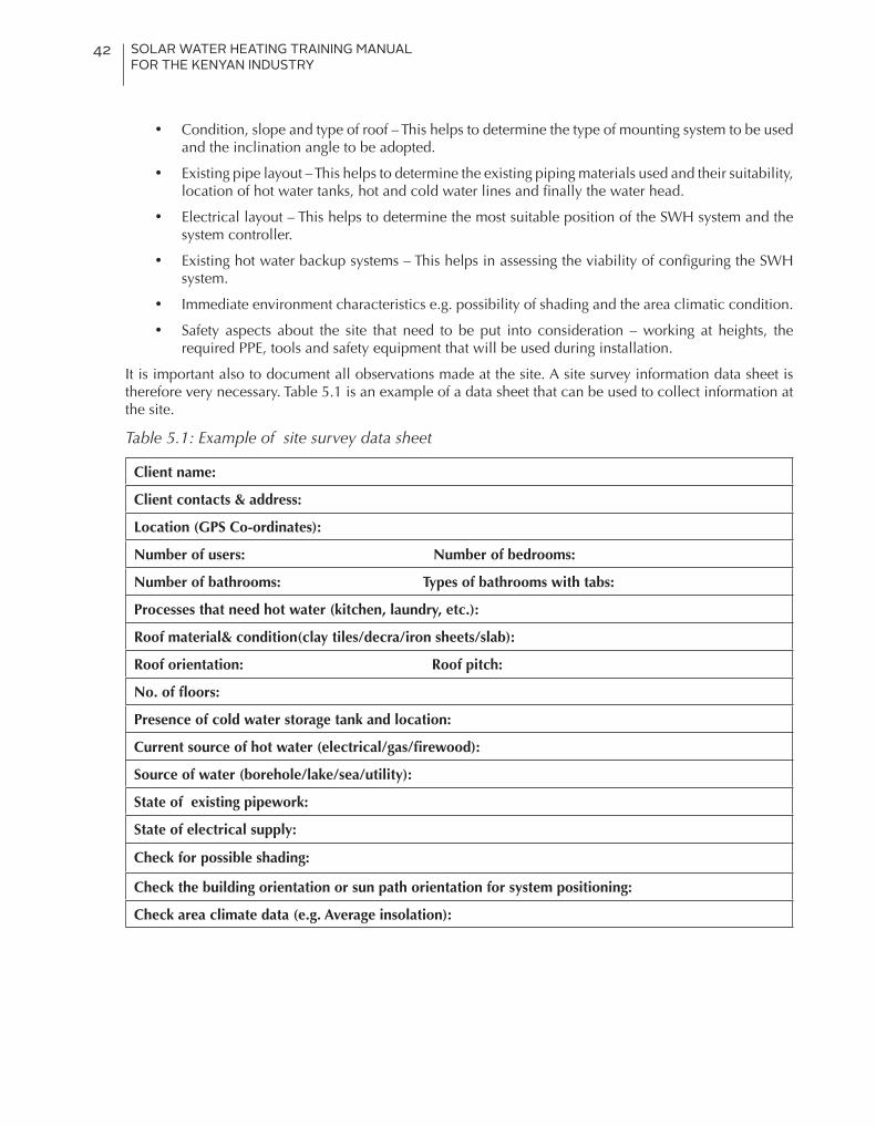
SOLAR WATER HEATING TRAINING MANUAL FOR THE KENYAN INDUSTRY
42
• Condition, slope and type of roof – This helps to determine the type of mounting system to be used and the inclination angle to be adopted.
• Existing pipe layout – This helps to determine the existing piping materials used and their suitability, location of hot water tanks, hot and cold water lines and finally the water head.
• Electrical layout – This helps to determine the most suitable position of the SWH system and the system controller.
• Existing hot water backup systems – This helps in assessing the viability of configuring the SWH system.
• Immediate environment characteristics e.g. possibility of shading and the area climatic condition.
• Safety aspects about the site that need to be put into consideration – working at heights, the required PPE, tools and safety equipment that will be used during installation.
It is important also to document all observations made at the site. A site survey information data sheet is therefore very necessary. Table 5.1 is an example of a data sheet that can be used to collect information at the site.
Table 5.1: Example of site survey data sheet
Client name:
Client contacts & address:
Location (GPS Co-ordinates):
Number of users: Number of bedrooms:
Number of bathrooms: Types of bathrooms with tabs:
Processes that need hot water (kitchen, laundry, etc.):
Roof material& condition(clay tiles/decra/iron sheets/slab):
Roof orientation: Roof pitch:
No. of floors:
Presence of cold water storage tank and location:
Current source of hot water (electrical/gas/firewood):
Source of water (borehole/lake/sea/utility):
State of existing pipework:
State of electrical supply:
Check for possible shading:
Check the building orientation or sun path orientation for system positioning:
Check area climate data (e.g. Average insolation):

SOLAR WATER HEATING TRAINING MANUAL FOR THE KENYAN INDUSTRY
43
5.1.2. System component sizingAfter gathering and recording the customer’s demand details, the next step is to use the collected data to determine the size of individual components. Refer to chapter 9 for minimum requirements on estimating hot water demand in Kenya and based on the collected data from the site.
Collector sizing
Sizing of solar collectors is based on the daily hot water demand and the available insolation at the particular site. Other observed parameters such as orientation of the roof or site will then dictate to what extent the size can be adjusted besides the two parameters.
After estimating the hot water demand, the area of the collector can be determined by first estimating the daily energy demand (hot water demand expressed as energy demand), then working backwards using the available insolation to get the area. Insolation in Kenya generally varies from 4-6kWh/m2/day.
Daily hot water energy demand (Refer to Table 9.2 of section 9.1.8)
The daily hot water energy demand (L) is calculated from;
Where; L = Daily hot water energy demand (kWh/day)
V = volume of water per day (m3/day)
= density of water (usually 1000kg/m3)
C = specific heat capacity of water (use 0.001167kWh/kgoC)
Thot = hot water delivery temperature (use 60 OC for Kenya)
Tcold = cold water temperature (usually 15 OC in Kenya)
Collector area
The collector area is then be calculated from;
Where, Ac = collector area
L = daily hot waterenergy demand
= Solar fraction (minimum of 60% for Kenya)
= Solar system efficiency (usually 40%)
Iav = Average daily solar insolation (kWh/m2/day)
NB: It is common practice and recommended to undersize than oversize solar water heating systems. Under-sizing can be accomplished by using the maximum insolation (Imax)of a particular site in the above equation and/or incorporating the solar fraction (Fsolar).

SOLAR WATER HEATING TRAINING MANUAL FOR THE KENYAN INDUSTRY
44
Example 5.1For a home with a daily hot water demand of say 300litres, the daily hot water energy demand and the collector area is calculated as;
As a general rule in Kenya, and for ease of calculations 1m2 of a flat plate collector is enough to heat up 75litres of water while the same size of evacuated tube type heats up 100litres. Generally, collector sizes available in the Kenyan market are 2m2 and 1.5m2 for flat plate types. For evacuated tubes,
Whereas the diameter of the tubes varies, the length is usually 1.8m. The area therefore must be calculated from the individual tube area (diameter× length) and the number of tubes making the collector.
AS a rule of thumb for collector sizing the following estimations can be used in sizing different types of collectors;
• 75l/m2 is used for flat plate collectors,
• 10l/tube for the evacuated tubes
• Swimming pool –(75 – 100%) of the surface area of the swimming pool.
Example 5.2Using the demand in example 5.1, the size of the collector would be 4m2 and 3m2 for flat plate and evacuated tube type respectively as illustrated below;
Table 5.2 shows typical collector sizes based on an average insolation of 5.6kWh/m2/day. The collector size will reduce for locations with higher insolation values or increase for locations with lower insolation such as Limuru for example. However, it is important to note that minor variations may not affect the collector size after all.
L = 0.3m3/day×1000kg/m3×0.001167kWh/kgoC×(60oC – 15oC) = 15.75kWh/day
Ac = (L× Fsolar) ÷(ηsolar×Iav) = (15.75kWh/day×0.6) ÷(0.4×5.6kWh/m2/day) = 4.2m2

SOLAR WATER HEATING TRAINING MANUAL FOR THE KENYAN INDUSTRY
45
Table 5.2: Example collector sizes for typical hot water demands
Demand Required Collector Area
Daily hot water demand Daily Energy Flat plate collector type
Evacuated tube type
(Litres) (m3) (kWh/day)Actual (m2)
Available (m2)
No. of collectors (2m2) (m2)
100 0.1 5.3 1.5 2 1 1
150 0.15 7.9 2 2 1 1.5
200 0.2 10.5 3 4 2 2
300 0.3 15.8 4 4 2 3
400 0.4 21.0 6 6 3 4
500 0.5 26.3 7 8 4 5
600 0.6 31.5 8 8 4 6
700 0.7 36.8 10 10 5 7
800 0.8 42.0 11 12 6 8
1000 1 52.5 14 14 7 10
1200 1.2 63.0 16 16 8 12
5.1.3. Storage tank sizeAs a rule of thumb the regulation requires that the minimum size of the tank to be 1.5 times the hot water demand due to over usage or overheating. The resultant daily hot water demand gives the size of the hot water storage tank. As in example 5.1,
The figure obtained after calculation is then rounded off to the commonly available tank sizes in the market.
For passive systems, horizontal tanks are recommended for ease of thermosiphon. Vertical tanks on the other hand are recommended for active systems as they allow for better stratification and economy of space.
5.1.4. PumpsIn Kenya, the most common way to supply the necessary water pressure to an SWH system is through a raised cold water storage tank. However, where this is not feasible, a pump may be suggested to the customer to increase water supply pressure. It is important to ensure optimal water flow in the system so that collectors work at the best efficiencies.
The pump size can also be estimated from the equation;
Where, P = pump capacity (kW), Q = flow rate (m3/h), ρ = density of water (kg/m3), g = acceleration due to gravity (m/s2) and h = head (m)
Most pumps are also rated in terms of hydraulic horsepower and this can be obtained by dividing the calculated capacity with 0.746.
The Figure 5.2 below shows typical charts used for pump selection. The flow rate and head required are used to determine the pump power rating and hence the pump model.
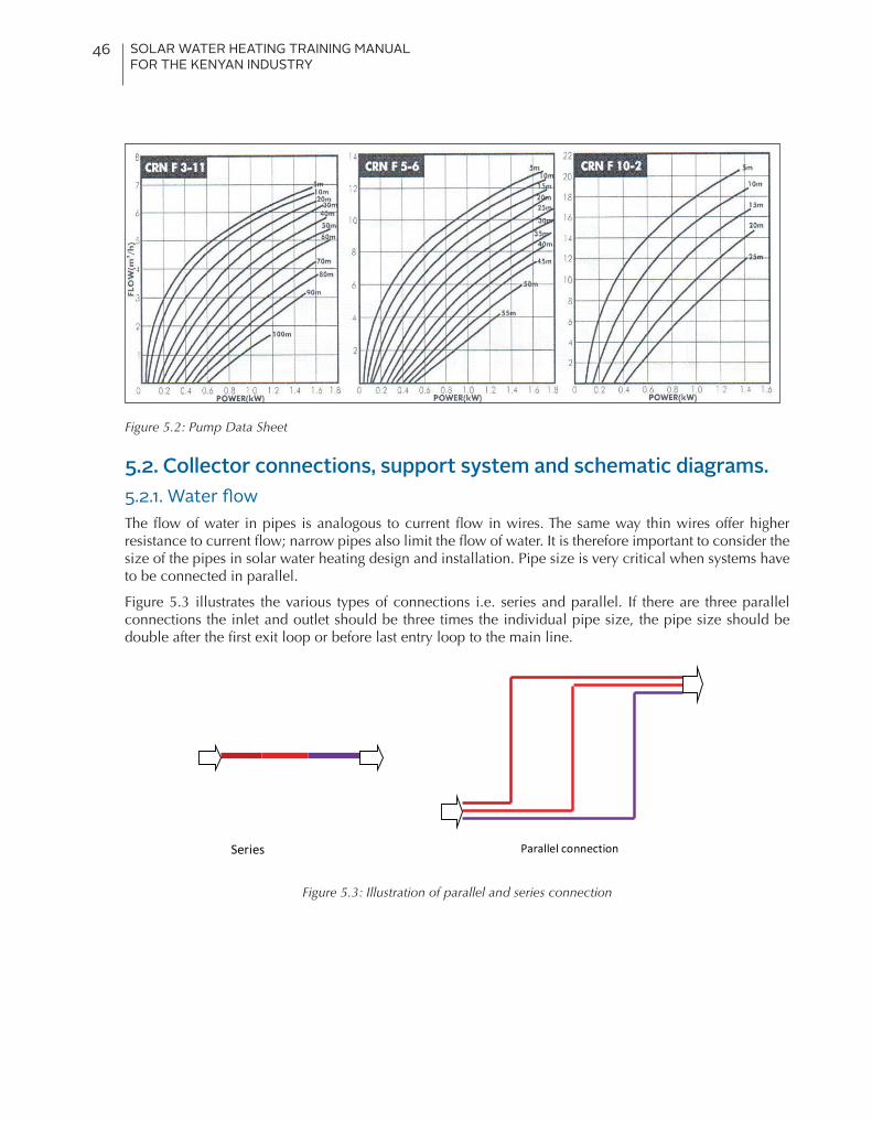
SOLAR WATER HEATING TRAINING MANUAL FOR THE KENYAN INDUSTRY
46
Figure 5.2: Pump Data Sheet
5.2. Collector connections, support system and schematic diagrams.5.2.1. Water flowThe flow of water in pipes is analogous to current flow in wires. The same way thin wires offer higher resistance to current flow; narrow pipes also limit the flow of water. It is therefore important to consider the size of the pipes in solar water heating design and installation. Pipe size is very critical when systems have to be connected in parallel.
Figure 5.3 illustrates the various types of connections i.e. series and parallel. If there are three parallel connections the inlet and outlet should be three times the individual pipe size, the pipe size should be double after the first exit loop or before last entry loop to the main line.
Seriesconnection
Parallelconnection
Figure 5.3: Illustration of parallel and series connection

SOLAR WATER HEATING TRAINING MANUAL FOR THE KENYAN INDUSTRY
47
5.2.2. Balanced connectionFor a solar water heating collector to function properly, it is also critical to ensure that water flows through the collector in a balanced way. Otherwise, water may take the shortest route. In principle, “first in – last out” concept must be ensured as shown in figure 5.4.
WRONG RIGHT
Figure 5.4: Balanced connection of collectors
5.2.3. Collector configurationsSolar collectors can be connected in series as well as in parallel. Ideally, parallel connection of collectors should be limited to four (4) while series connection should be limited to three (3) but manufacturer’s recommendation should take precedence. Series connections are only preferred when they involve complete systems as discussed further under the multiple systems section.
Figure 5.5: Parallel and series connected collectors

SOLAR WATER HEATING TRAINING MANUAL FOR THE KENYAN INDUSTRY
48
5.2.4 Designing multiple SystemsFor commercial systems, a mix of both parallel and series connections is employed. Therefore, the entire system is composed of smaller sub-systems connected either in series or parallel. Figures 5.6 and 5.7, show the correct and incorrect ways of connecting systems in parallel.
Figure 5.8 shows series connection of multiple systems. A maximum of five sub-systems is however recommended.
Figure 5.6: Parallel connection of multiple systems
Figure 5.7: Imbalanced parallel connection of multiple systems
Figure 5.8: Series connection of sub-systems
NOT RECOMMENDED

SOLAR WATER HEATING TRAINING MANUAL FOR THE KENYAN INDUSTRY
49
PressureGauge
FlowMeter
AirVent
Pump
AirPurge
Flush&FillValves
strainer
ExpansionTank
HeatExchanger
AirVent
Pump
strainer
Controller
TemperatureSensor
ElectricHeatingElement
StorageTank
ColdWaterIn
TemperingValve
ConventionalWaterHeater
HotWaterOut
IsolationValves
TemperatureSensor
AirVentandPressure/TemperatureReliefValve
Fig 5.9: Parallel connected SWH system with vertical storage tanks (Andy Walker, 2013)
5.2.5. Mounting structure designFor flat roofs or ground mounts, mounting structures should be designed with the tilt angle in mind. It should be between 15-20o for Kenya. Larger systems with separate mounts should be designed in a way that they don’t cast shadows on others after installation.
For pitched or tilted roofs, the type of roofing material will determine the kind of structure to be used. When choosing the type of mount to be used one should consider two aspects;
• The possibility of using a mount with roof angle adjustments
• Impacts of using the roof-angle/slope on the collector capacity.
When mounting SWH systems, the edge clearance should be at least 200mm and the roof surface clearance should be a maximum of 50mm. Besides limiting wind flow under the system, it also prevents birds from nesting under the systems.
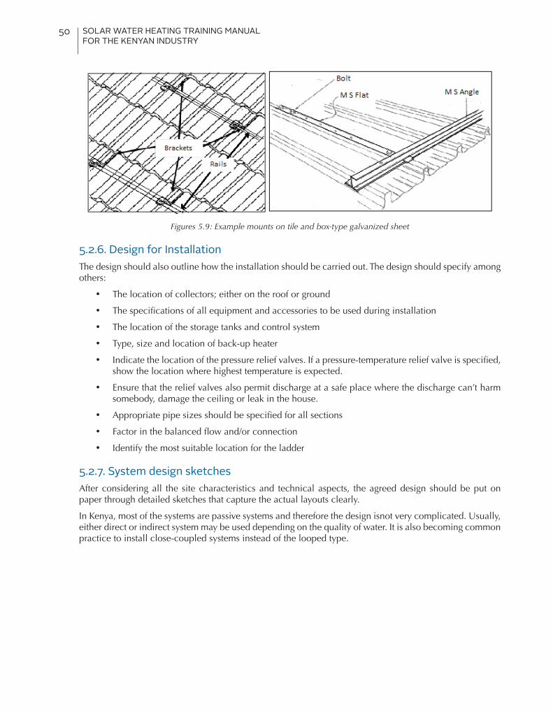
SOLAR WATER HEATING TRAINING MANUAL FOR THE KENYAN INDUSTRY
50
Figures 5.9: Example mounts on tile and box-type galvanized sheet
5.2.6. Design for InstallationThe design should also outline how the installation should be carried out. The design should specify among others:
• The location of collectors; either on the roof or ground
• The specifications of all equipment and accessories to be used during installation
• The location of the storage tanks and control system
• Type, size and location of back-up heater
• Indicate the location of the pressure relief valves. If a pressure-temperature relief valve is specified, show the location where highest temperature is expected.
• Ensure that the relief valves also permit discharge at a safe place where the discharge can’t harm somebody, damage the ceiling or leak in the house.
• Appropriate pipe sizes should be specified for all sections
• Factor in the balanced flow and/or connection
• Identify the most suitable location for the ladder
5.2.7. System design sketchesAfter considering all the site characteristics and technical aspects, the agreed design should be put on paper through detailed sketches that capture the actual layouts clearly.
In Kenya, most of the systems are passive systems and therefore the design isnot very complicated. Usually, either direct or indirect system may be used depending on the quality of water. It is also becoming common practice to install close-coupled systems instead of the looped type.

SOLAR WATER HEATING TRAINING MANUAL FOR THE KENYAN INDUSTRY
51
Figure 5.10: Direct passive system
Figure 5.11: direct active systems

SOLAR WATER HEATING TRAINING MANUAL FOR THE KENYAN INDUSTRY
52
Figure 5.12: Indirect active system with heat exchanger in pump station

SOLAR WATER HEATING TRAINING MANUAL FOR THE KENYAN INDUSTRY
53
5.2.8. Bills of QuantitiesThe last part of the design is to generate a material bills of quantities based on the design layout.
Table 5.2: Example bills of quantity sheet
S/N Item Specs Qty S/N Item Specs Qty
1 Collectors m2 19 Hot water pipes ½’’
2 Hot water tank lts 20 Hot water pipes ¾’’
3 Glycol lts 21 Hot water pipes 1’’
4 PTR valves ½’’ 22 Gate valves 1’’
5 Thermosiphon arrestor valves ½’’ 23 Gate valves ¾’’
6 Tempering valves ½’’ 24 Sockets ½’’
7 Thermostatic valves ½’’ 25 Sockets ¾’’
8 Non-return valves ½’’ 26 Sockets 1’’
9 Brass plugs ½’’ 27 Nipples ¾’’
10 Collector unions ½’’ 28 Nipples 1’’
11 Connection unions ½’’ 29 Tees ½’’
12 Hot water tees ½’’ 30 Tees ¾’’
13 Nipples ½’’ 31 Tees 1’’
14 Booster heater kW 32 Elbows ½’’
15 Solar controller 33 Elbows ¾’’
16 Solar pump 34 Collector brackets
17 Sensor fitting and probes 35 Collector rails
18 Expansion tank 36 Mounting structure

SOLAR WATER HEATING TRAINING MANUAL FOR THE KENYAN INDUSTRY
54
6. Installation of Solar Water Heating SystemsIn Kenya, SWH systems are imported as completely knocked-out kits or semi-assembled kits which are then assembled into some standard systems that comply with the local standards set by KEBs. There also exist some local manufacturers of some of the components.
In either case, systems are generally:
• Indirect systems - meant to cater for hard water, borehole water and water with sedimentation and soluble salts e.g. coast region
•Direct systems - for use with soft or treated water
6.1. ToolsBasically the tools needed for assembling the solar water heater systems are common plumbingand masonry tools, summarised in Table 6.1.
Table 6.1: Common solar water heating installation tools
a) Die stock b) Pipe vices c) Pipe wrenches
d) Adjustable spanners e) Hacksaw f) PPR pipe fuser or welder
g) PPR pipe cutter
h) Hand drill and bits i) Ordinary hammer j) Masonry hammer and chisel
Other tools may include tape measures, spirit levels, pliers, screws, set of spanners and rope. Other accessories include: screws, nails, nut & blots.
Hoisting of tanks and collectors is currently done manually using ladders and scaffolds as the use of mechanized cranes would be expensive. On high-rise buildings, service lifts or staircases are used.

SOLAR WATER HEATING TRAINING MANUAL FOR THE KENYAN INDUSTRY
55
6.2. Health and safetyThe following safety measures should be taken while working at heights:
• The scaffolding must be properly secured and the installers must wear harnesses as well as reflective jackets.
• The site should be properly secured and marked.
A checklist needs to be prepared to address the regulatory and legal requirements in order to address the job risk at site. This will vary from one service provider to another.
Insurance and medical covers may be procured for the installers and the public as the workman’s compensation is not adequate in some cases.
6.3. Material checklist and design drawingsThe material checklist, prepared as per the system during design phase should be used to confirm that all the necessary materials are at the site. The installer should ensure that the design drawings reflects the site conditions and follow all the instructions during installations.
6.4. Mounting framesThe rule of thumb while mounting frames, is that it is always advisable to put an insulating material e.g. rubber between the roof and the frame to prevent possible reaction such as corrosion.
For tiled roofs, the support straps are screwed firmly onto the rafters/beams and not the battens. This requires the removal of some tiles in order to access the underlying rafters. The support bracket should be bent to run flush with the rafter so as not to press onto the tile so that it does not break.
Figure 6.1: Standoff roof mounting structure on a tiled roof

SOLAR WATER HEATING TRAINING MANUAL FOR THE KENYAN INDUSTRY
56
For galvanised iron sheet roofs, the roofing screws used to support the mounting bracket must pass through the roof and into the rafter (roof structure). Separation materials/rubber pads should be used with the roofing screws to lift the metal frame off the roof to prevent corrosion due to dissimilar metals coming into contact with each other (galvanic corrosion).
Figure 6.2: Flat Plate collector mounted on ordinary galvanized and box-type iron sheet roofs (Refer to Figure 5.9 for installation guideline)
All pipes and sensor penetrations into the roof must be sealed with good quality permanent sealants such as silicone, urethane or butyl rubber in accordance with good roofing practices.
An alternative to roof mounting is ground mounting where the collector is mounted at the ground level. The lower edge of the collector should be raised at least 0.5m above the ground to avoid shading by growing vegetation.
6.5. Installation of collectorsAll genuine solar collectors will have installation manuals and a warranty. This is to ensure that the installed systems perform to the manufacturer’s specifications.
Always refer to the manufactures instruction and proper handling of the evacuated tube is especially emphasized as they are fragile and delicate.
While installing, the collectors should be tilted at an angle as per manufacturers’ instruction facing north. Where roofs are not ideal for the south-north orientation, then the west side of the roof is considered. (The ground mounting is ideal mainly for solar farms). Mounting of the collectors to the frame varies from one manufacturer to another and technical manuals are always provided with each unit.
Where the design of the manifold has not taken into consideration tilting to allow hot water to rise, there will be need to slightly tilt (by less than 20mm).
The collectors are lifted to the roof in their packaging material to avoid scratches and unpacked when being fitted on the frame. Once the system is completely installed but not commissioned it should be covered with a suitable material as to prevent system damage due to excessive heating.
For an ongoing construction site, the collectors are the last to be installed to avoid damage due to flying debris. This should also be the case with a system that is to be left idle for a long period of time. The system has a provision for a pressure relief valve which is left open to avoid damaging the system and the pressure relief valve fitted during commissioning. pressure release valve to prevent explosion of the tank due to excessive pressure due to heat which is fitted at the highest point of the tank. Other systems have cold pressure release valve which helps in conserving the much needed hot water.
Additionally, during the installation phase, both ends of the collectors are left open until commissioning phase.

SOLAR WATER HEATING TRAINING MANUAL FOR THE KENYAN INDUSTRY
57
Figure 6.3: Collector and evacuated tube mounted on roof tops
6.6. Installation of TanksCranes are recommended for lifting the tanks up the roof. In Kenya however, this is not common as they are expensive. Tanks are therefore lifted manually with ropes, via ladders and scaffolding. In some cases, service lifts are used to bring the tanks closer to the roof area.
The tanks are lifted while still wrapped in their packaging materials, to avoid scratches and damage. When securing the tanks, either in passive or active system, manufacturer’s instructions should be followed, taking into account the ease of system maintenance.
The layout of piping and valves associated with a system should be done professionally, whilst considering the electrical cables termination points.
Figure 6.4: Storage tanks and collectors mounted on rooftops
6.7. Back-up heaterThe electrical back-up heater, should be secured into the tank in a leak-tight manner. Provision for weatherproof electrical cables should be made, and electrical connections carried out by qualified personnel. The switch should not be installed until the entire system is complete and the tank full of water.
NB. For back up heating purposes; during commissioning the technician should check that the thermostat is set to the right temperature (55 -60°C), this settings also aid in bacteria management.

SOLAR WATER HEATING TRAINING MANUAL FOR THE KENYAN INDUSTRY
58
6.8. PipeworksAll pipe works around the collectors and storage tanks should conform to the manufacturer’s recommendation. The rest of the plumbing works should be guided by the design specifications. Sharp bends should be avoided at all cost to avoid air locks. Where different metals are used in the system a brass coupling should be used to avoid reaction.
6.9. InsulationAll hot water pipes should be insulated: Lagged or cladded with polyethylene or neoprene foam and covered with aluminium foil (when externally used) to prevent heat loss. All valves, booster heater caps and cold water supply near the hot water storage tank should also be insulated. Exposed electrical cables should be sheathed or conduit trunking used for insulation.
6.10. Water supplyIncoming water supply should be at least 1.5m higher than the system for passive systems and should be provided with protection valves and filters all of which should be accessible. Pressure reduction valves are only recommended when using high pressure systems e.g. mains water supply system.
6.11. Valves• All valves should be installed correctly facing the right direction and should drain into a safe
location.
• Temperature pressure relief (TPR) valves should be fitted on the upper part of the panels in split systems and on upper part of cylinders for coupled systems.
• Thermostatic mixing valves should be fitted at the system outlet to regulate the water temperatures to enable usage of low pressure pipes in household.
• Multi way valve should be fitted according to the manufactures manual.
6.12. Pumps and controlsThe solar pump and controller should be fitted and adjusted as per the requirements. Electrical connections should be done by qualified personnel.
6.13. Tidying up• All waste generated on the roof during installation should be cleared and the roof left clean as
drill waste rusts very quickly causing the roof to rust too.
• Perforations made on the roof should be sealed with silicon or other suitable sealants including rubber boots where the pipes go through the roofs.
• Drills or trunks made on walls should be plastered and re-painted. Ceilings and any other sections of the building made dirty should also be tidied up.
• Insulation chippings should be cleaned up and water flow direction markings done on the insulated pipes.

SOLAR WATER HEATING TRAINING MANUAL FOR THE KENYAN INDUSTRY
59
7. System Commissioning
After the system is installed, it must be checked and tested to ensure that it is functioning properly and safe to use. System commissioning involves:
• Visual inspection of the installation to ensure it is well done• Testing of various operational parameters as per the manufacturers’ manuals• Educating the user• Issuing of user-guide or one provided by the manufacturer • Completion and signing of the commissioning form and certificate.
It should be emphasized that failure to commission the system as per the manufacturer’s manuals may invalidate warranty and insurance terms.
Completion of the commissioning is actually the point at which the responsibility for the installed system is passed on to the customer. It is desirable to commission a SWH system on a sunny day with the collector temporarily covered. The end-user should be advised to let the commissioned system tune up for two days before using it.
7.1. What to check for during commissioningThe following aspects should be checked properly during commissioning.
• Visual inspection of the system installation and workmanship to ensure proper installation and that the area is left clean. Ensure that there is no obstacle (building, tree, etc.) shading the solar collector or a part of it. Ensure ladders, scaffolds or safety tapes installed during installation are removed from the site. Any dug-outs should also be filled up.
• Verification of whether the installed components meet the stated specifications
• The system should be flushed out with cold water to ensure that any dirt inside the piping is removed. Ensure that there is no blockage and that the non-return valves, gate valves, PT valves and thermostatic mixing valves are properly installed and are easily accessible.
• Ensure that there is no air trapped inside the collector and the storage tank
• Testing for leaks should be done by carrying out a test run and pressurizing the system for at least 24 hours before handing over to the owner.
• Verify that the booster/back-up heater is working as required and confirm the correct operation of the thermostats and safety controls.
Note: The electrical booster should be tested after the leak testis done and when the storage tank is full.
• The controller should also function properly and be able to measure the output water temperature accurately.
• Verify that the system is well insulated to reduce heat losses.
• Check the fluid level for the closed circuit (indirect systems) and fill it, if necessary.
• Check all the pipes and ensure they are well placed and adequately secured or clipped.
• Verify that the various parameters such as the flow rate, pressure and temperature of the various components are as designed. The variable settings critical to the performance of the system are adjusted, set and recorded.

SOLAR WATER HEATING TRAINING MANUAL FOR THE KENYAN INDUSTRY
60
7.2. End-user educationThe general operation of the system should be fully explained to the user including the location and operation of all safety features.
Information relevant to the day to day running of the solar water heating system should be handed over to the client. It should include
• Full system operation instructions• Easy to use user-guide• Maintenance schedule• Decommissioning schedule• Copy of commissioning and completion certificate• Schematic diagram and any other relevant information including photos of the installed system.
The client should be advised to disconnect the booster and cover the panels or tubes to avoid pressure build up that can cause accidents whenever they are to leave the system unused for a long period of time.
7.3. Commissioning documentsIt is important to make sure that the consumer understands and signs the commissioning form as well as the certificate. Failure to do this implies that the system was not handed over correctly. A sample form and sample commissioning certificate are shown in tables 7.1 and 7.2.
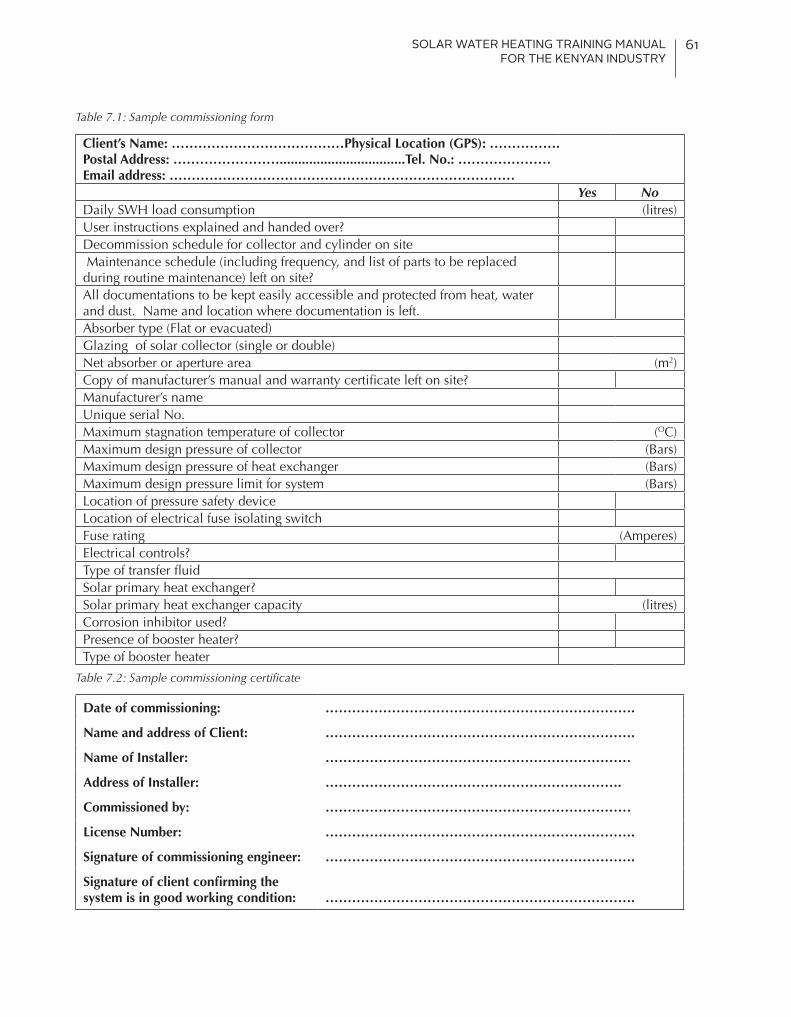
SOLAR WATER HEATING TRAINING MANUAL FOR THE KENYAN INDUSTRY
61
Table 7.1: Sample commissioning form
Client’s Name: …………………………………Physical Location (GPS): …………….Postal Address: ……………………..................................Tel. No.: …………………Email address: ……………………………………………………………………
Yes NoDaily SWH load consumption (litres)User instructions explained and handed over?Decommission schedule for collector and cylinder on site Maintenance schedule (including frequency, and list of parts to be replaced during routine maintenance) left on site?All documentations to be kept easily accessible and protected from heat, water and dust. Name and location where documentation is left.Absorber type (Flat or evacuated)Glazing of solar collector (single or double)Net absorber or aperture area (m2)Copy of manufacturer’s manual and warranty certificate left on site?Manufacturer’s nameUnique serial No.Maximum stagnation temperature of collector (OC)Maximum design pressure of collector (Bars)Maximum design pressure of heat exchanger (Bars)Maximum design pressure limit for system (Bars)Location of pressure safety deviceLocation of electrical fuse isolating switchFuse rating (Amperes)Electrical controls?Type of transfer fluidSolar primary heat exchanger? Solar primary heat exchanger capacity (litres)Corrosion inhibitor used?Presence of booster heater?Type of booster heater
Table 7.2: Sample commissioning certificate
Date of commissioning: …………………………………………………………….
Name and address of Client: …………………………………………………………….
Name of Installer: ……………………………………………………………
Address of Installer: ………………………………………………………….
Commissioned by: ……………………………………………………………
License Number: …………………………………………………………….
Signature of commissioning engineer: …………………………………………………………….
Signature of client confirming the system is in good working condition: …………………………………………………………….
SOLAR WATER HEATING TRAINING MANUAL FOR THE KENYAN INDUSTRY
62
8. System Maintenance and Trouble Shooting8.1. System MaintenanceSolar water heating systems are low maintenance systems. Frequency of maintenance depends on the ambient temperature, conditions of the area e.g. dust, quality of water, etc. Typical maintenance periods are after every six months.
• In an indirect system, the heat transfer fluid evaporates after sometime and should be replenished as and when necessary;
• Depending on the water quality flushing the systems should be done in determined period due to sediments. A filter should also be installed in the supply side and should be serviced regularly;
• TPR valve should be exercised regularly to ensure that it is working properly;
• The sacrificial anode should be checked and replaced as necessary;
• Plumbing works and cladding should be checked regularly, leaks repaired and worn out cladding replaced;
• Check for shading and correct as necessary ;
• Clean the collectors regularly especially during dry seasons.
• Check on the electrical installation and all controls.
• In evacuated tubes check for change in colour (indicating breakage) and replace;
• Follow manufacturer’s instructions on maintenance of components.
• Keep records of maintenance activities
8.2. System TroubleshootingIt is important to consult the user on the malfunctioning of the system, any changes in or around the system and find out if the system has been interfered with. As a rule of thumb, ensure the water in the system is at ambient temperature, close all inlets and outlets, allow the system to sit for a whole sunny day, test the water temperature at the end of the day to confirm effective heating. If the heating is effective, then the fault is in the plumbing and distribution of the hot water. Table 8.1 gives a guide on what to look for while troubleshooting a system.
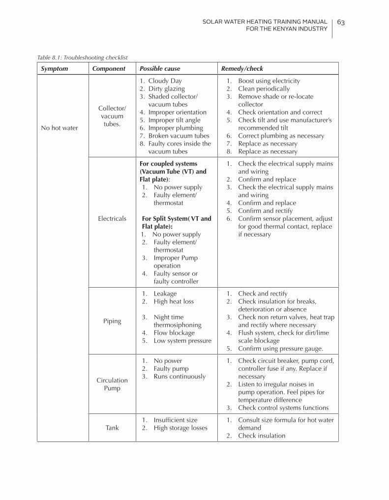
SOLAR WATER HEATING TRAINING MANUAL FOR THE KENYAN INDUSTRY
63
Table 8.1: Troubleshooting checklist
Symptom Component Possible cause Remedy/check
No hot water
Collector/ vacuum tubes.
1. Cloudy Day2. Dirty glazing3. Shaded collector/
vacuum tubes4. Improper orientation5. Improper tilt angle6. Improper plumbing7. Broken vacuum tubes8. Faulty cores inside the
vacuum tubes
1. Boost using electricity2. Clean periodically3. Remove shade or re-locate
collector4. Check orientation and correct5. Check tilt and use manufacturer’s
recommended tilt6. Correct plumbing as necessary7. Replace as necessary8. Replace as necessary
Electricals
For coupled systems (Vacuum Tube (VT) and Flat plate):1. No power supply 2. Faulty element/
thermostat
For Split System( VT and Flat plate):1. No power supply 2. Faulty element/
thermostat3. Improper Pump
operation4. Faulty sensor or
faulty controller
1. Check the electrical supply mains and wiring
2. Confirm and replace3. Check the electrical supply mains
and wiring4. Confirm and replace5. Confirm and rectify6. Confirm sensor placement, adjust
for good thermal contact, replace if necessary
Piping
1. Leakage 2. High heat loss
3. Night time thermosiphoning
4. Flow blockage5. Low system pressure
1. Check and rectify2. Check insulation for breaks,
deterioration or absence3. Check non return valves, heat trap
and rectify where necessary4. Flush system, check for dirt/lime
scale blockage5. Confirm using pressure gauge.
Circulation Pump
1. No power2. Faulty pump3. Runs continuously
1. Check circuit breaker, pump cord, controller fuse if any. Replace if necessary
2. Listen to irregular noises in pump operation. Feel pipes for temperature difference
3. Check control systems functions
Tank1. Insufficient size2. High storage losses
1. Consult size formula for hot water demand
2. Check insulation

SOLAR WATER HEATING TRAINING MANUAL FOR THE KENYAN INDUSTRY
64
Symptom Component Possible cause Remedy/check
Not enough hot water
1. Leakage2. Usage
1. Confirm and rectify2. Increase the system capacity
No hot water in the morning
Non return valve
Stuck open (night time thermosiphoning)
Confirm and rectify
Noisy system
Pump
1. Bearing needs lubrication
2. Air locked
1. Service the pump
2. Loosen vent to bleed air from the system
Piping
1. Entrapped air (direct systems)
2. Pipe Vibration
1. Clean system by running water through
2. Insulate pipes from walls and each other
High electrical power consumption
Tank Thermostat set at high level
Check setting and adjust or replace if faulty
Timer Setting not properly done Reset the timer to appropriately match with usage
1. Shading2. weather
condition
Element working for longer hours
1. Remove obstacles or reposition collectors
2. Inform client and on weather
MAINTENANCE SCHEDULE
Maintenance Schedule Recommended period of duty
Cleaning collector glass As appropriate
Check system operation Every 6 months
Check for leakage Every 6 months
Check scaling/descaling if required As appropriate
Check for shading Regularly
Exchange of anti-freeze Every year

SOLAR WATER HEATING TRAINING MANUAL FOR THE KENYAN INDUSTRY
65
9. Compliance Requirements for Solar Water Heating
IntroductionThe design and installation of solar water heating systems is a specialized and highly technical engineering sector that requires strict compliance with regulations. The regulatory framework for the solar water heating industry in Kenya entails compliance with the following requirements:
1. The Energy (Solar Water Heating) Regulation 2012
2. Building code 2009
3. Occupational Safety and Health Act (OSHA) 2007
4. Environmental Management and Coordination Act 1999
5. Work Man Injury Benefit Act 2007
6. The relevant Kenyan standards KS 1860:2008
9.1. The Energy (Solar Water Heating) RegulationsThe Energy (Solar Water Heating) Regulations clearly outlines the compliance requirements for premises to install solar water heating systems.
The Regulations require that:
• Premises within a jurisdiction of a local water authority using over 100 Litres of hot water are required to have a SWH system installed.
• An owner of premises, Architect and an Engineer engaged in the design, construction, extension or alteration of premises shall incorporate solar water heating systems in all new premises designs and extensions or alterations to existing premises.
• An owner or occupier of premises that has a solar water heating system shall use and carry out the necessary operational maintenance and repairs required to keep the installation in good and efficient working condition and any other premises the commission determines.
9.1.1. Time frame• For existing buildings, a 5-year transition period until 25 May, 2017 has been given for all
premises to comply
• For buildings built after gazettement of the regulations on 25 May 2012, SWHs should be part of the architectural design before construction commences.
9.1.2. Solar water heater installation works• One shall NOT carry out installation works unless they are licensed by the ERC. This is applicable
to both the contractor and the technician
• The installation shall comply with the relevant Kenyan standards
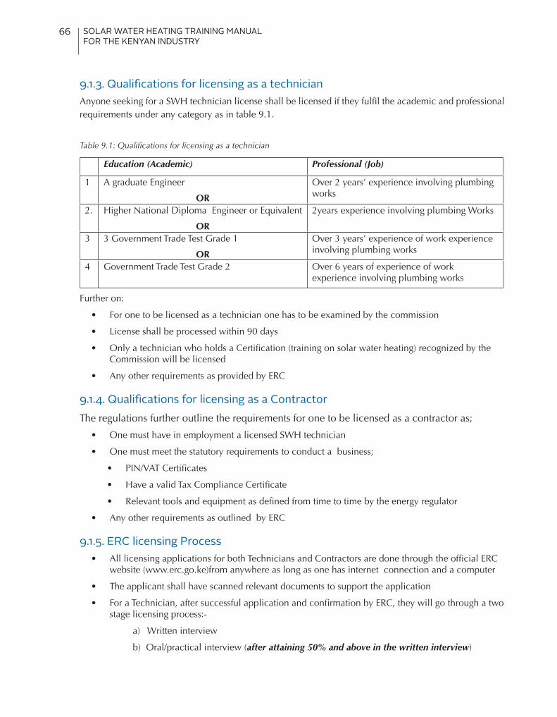
SOLAR WATER HEATING TRAINING MANUAL FOR THE KENYAN INDUSTRY
66
9.1.3. Qualifications for licensing as a technicianAnyone seeking for a SWH technician license shall be licensed if they fulfil the academic and professional requirements under any category as in table 9.1.
Table 9.1: Qualifications for licensing as a technician
Education (Academic) Professional (Job)
1 A graduate Engineer
OR
Over 2 years’ experience involving plumbing works
2. Higher National Diploma Engineer or Equivalent
OR
2years experience involving plumbing Works
3 3 Government Trade Test Grade 1
OR
Over 3 years’ experience of work experience involving plumbing works
4 Government Trade Test Grade 2 Over 6 years of experience of work experience involving plumbing works
Further on:
• For one to be licensed as a technician one has to be examined by the commission
• License shall be processed within 90 days
• Only a technician who holds a Certification (training on solar water heating) recognized by the Commission will be licensed
• Any other requirements as provided by ERC
9.1.4. Qualifications for licensing as a ContractorThe regulations further outline the requirements for one to be licensed as a contractor as;
• One must have in employment a licensed SWH technician
• One must meet the statutory requirements to conduct a business;
• PIN/VAT Certificates
• Have a valid Tax Compliance Certificate
• Relevant tools and equipment as defined from time to time by the energy regulator
• Any other requirements as outlined by ERC
9.1.5. ERC licensing Process• All licensing applications for both Technicians and Contractors are done through the official ERC
website (www.erc.go.ke)from anywhere as long as one has internet connection and a computer
• The applicant shall have scanned relevant documents to support the application
• For a Technician, after successful application and confirmation by ERC, they will go through a two stage licensing process:-
a) Written interview
b) Oral/practical interview (after attaining 50% and above in the written interview)
SOLAR WATER HEATING TRAINING MANUAL FOR THE KENYAN INDUSTRY
67
• If a Technician fails in the written or oral interviews he/she can resit after 3 and 6 months respectively
§For a Contractor, after successful application and confirmation by ERC, an inspection shall be scheduled and conducted at the contractor’s premise in the presence of a licensed Technician in the contractor’s employment.
9.1.6. Premises required to install solar water heating systems• Domestic residential houses
• Education institutions e.g. Colleges, Boarding Schools, Universities
• Health institutions e.g. Hospitals, Health Centres, and similar medical facilities
• Hotels, Hostels, Lodges and similar premises providing boarding services.
• Restaurants, cafeterias and similar eating places
• Laundries
9.1.7. Exemption for premisesExemption criteria
The commission may exempt premises from installing SWH systems based on the following criteria;
• Buildings with technical limitations
• Premises incapable of incorporating SWH systems due to special circumstances e.g. State House and military premises
• Premises already supplied with hot water from a co-generation plant.
• Premises utilizing electricity generated from renewable energies and where the excess electricity is used as a dump load to heat water.
• Such a premise as the Commission may determine
Application procedure
• An application for an exemption shall be made to the commission in form 1 set out in the first schedule of the regulation before submission of the building plans for approval to the relevant local authority.
• The application for exemption shall be accompanied by a Technical report by a registered Engineer or a registered Architect explaining why it is not technically viable to have a SWH system installed in the premises.
• It shall be processed within 45 days from application submission

SOLAR WATER HEATING TRAINING MANUAL FOR THE KENYAN INDUSTRY
68
9.1.8. Hot water demand calculation and minimum solar contribution guidelinesThe hot water demand estimates shall follow and apply the guidelines outlined in table 9.2
Table 9.2: Hot water demand guidelines
Type of Building Premises Specific Daily Hot Water Demand (DHWD) in litres per day at 60ºC
Domestic residential houses 30 per person
Educational institutions such as colleges and boarding schools
5 per student
Health institutions such as Hospitals, Health Centres, clinics and similar medical facilities
50 per bed
Hotels, Hostels, Lodges and similar premises providing boarding services
40 per bed
Restaurants, Cafeterias and similar eating places 5 per meal
Laundries 5 per kilo of clothes
Further;
i. All premises shall have a minimum annual solar contribution of 60% to the premises’ hot water demand. This means that 40% can come from other sources even if not from renewable sources. Normal practice is however to size for a 100% because of economics of installation and operation
ii. Hot Water Demand calculations at other temperatures (T) shall be adjusted for the 60oC reference temperature. For the purposes of making the adjustment, the following equation shall be used:
D (T) = D (T60) x (T-15)/45
The equation assumes that the cold water temperature (inlet water temperature) is 15ºC and a linear relationship. 45ºC is the difference between 60oC and 15oC
iii. For buildings with seasonal variations in hot water demand such as hotels, game lodges and similar premises, the demand may be adjusted by an annual occupancy rate of factor of not less than 70%
iv. In calculating demand, it shall be assumed that the daily hot water demand is constant, throughout the year
v. In calculating demand for domestic residential houses, the number of persons shall be taken to be equal to the number of bedrooms x 1.5
vi. In calculating the heat load of solar water heating system, heat losses in the hot water distribution system shall be taken into account.

SOLAR WATER HEATING TRAINING MANUAL FOR THE KENYAN INDUSTRY
69
9.1.9. Technician and Contractor obligations upon commissioning of a SWH system
• Regulation 10 (4)covers the issue and process of issuing an Installation Certificate to the system owner which should include:-
a) Date of installation.
b) Capacity of the SWH system.
c) Details of installer (Technician and/or Contractor).
d) Warranty period for the SWH system.
• A license shall be renewed every two (2) years and the application for renewal shall be made at least thirty (30) days before expiry.
• Records of all SWH systems installed shall be maintained specifying the location, capacity and type
• Annual returns shall be filed within the first quarter of the succeeding year
• The records of all SWH systems reports shall also be kept safe for a minimum period of five (5) years.
• The system user/owner shall also be trained and appropriate operation and maintenance manuals supplied.
9.1.10. Penalties under the regulationsThere will be a fine not exceeding one million shillings and/or an imprisonment of a term not exceeding one year for the following offences:
[1] Owners or occupiers of premises not installed with SWH systems
[2] A developer of a housing estate, Promoter of the construction, an Architect or Engineer engaged in the design or construction of the premises without incorporating SWH systems
[3] An owner or occupier of a premise for not carrying out necessary operational maintenance of the SWH systems
[4] An electric power distributor or supplier who connects electricity to a premise not installed with a SWH system
[5] A technician or contractor who does not maintain records of SWH systems installed
Regulation 7(5) further subjects a person who fails to comply with a notice issue by ERC to a fine not exceeding ten thousand shillings for residential premises and thirty thousand shillings for other premises for each day or part thereof that the contravention continues:
9.2. Building Code 2009 [clause NN 31.5 (a)]Under legal requirements, solar heating systems that must be incorporated into buildings have to comply with these regulations in so far as they affect such matters as the materials of construction, roof loading, weather tightness, fire resistance, insulation etc. Responsibility for the application rests with the local authority and may require plans deposited to show compliance as per KS 1860: 2009
All new housing developments or alterations and extensions to existing buildings should have solar hot water heating installations for bathroom use. No new housing development should be allowed to use the national grid electricity for hot water heating in bathrooms
SOLAR WATER HEATING TRAINING MANUAL FOR THE KENYAN INDUSTRY
70
9.3. Occupational Safety and Health Act (OSHA) 2007Installation of SWH systems must also abide by the requirements of OSHA, 2007.This is more so with regard to potential risks associated with such installations and reference is make to the following subsections;
i) Subsection 63 - Hoists and lifts
[1] They should be in good condition.
[2] Should be examined at least twice a year or after any modifications by approved persons from the directorate. The results of the examination should be filed and attached to the general register within 14 days of examination.
[3] The platform for the hoist should be secured or enclosed.
[4] The hoist should have maximum working load clearly marked.
ii) Subsection 64 - chains, ropes & lifting tackles
[1] They should be of good and sound material and free from any defects.
[2] Safe working load should be displayed within the site.
[3] The load should not exceed the stated working load.
[4] They should be examined at least once every 6 months by approved persons from the directorate.
iii) Subsection 65 - cranes and other lifting machines
[1] They should be of good and sound material and free from any defects.
[2] They should be examined at least once every 12 months by approved persons from the directorate.
[3] They should be tested before the first use.
[4] The maximum working load should be clearly marked.
[5] The load should not exceed the stated working load.
[6] Persons working near the cranes should be at least 6 meters away from the moving crane.
[7] They should be operated by a trained person.
iv)Subsection 66 - register
§ A register containing details such as workplace name, address, location etc should be kept.
v) Subsection 75 - Ladders
[1] They should be of good and sound material and free from any defects.
[2] They should be securely fixed firm on the ground.
vi) Subsection 101 - Protective Equipment
§ All employees should be provided with adequate PPEs.
9.4. Environmental Management and Coordination Act 1999All waste generated during installation and decommissioning of SWH systems should be segregated and disposed of according to the regulations stated in EMCA 1999 and the Waste Management Regulations, 2006.
SOLAR WATER HEATING TRAINING MANUAL FOR THE KENYAN INDUSTRY
71
9.5. Workman Injury Benefit Act 2007The act states that, in case of an injury/accident/occupational disease, the worker should report to the employer who then reports the same to the directorate using the official prescribed forms for commencement of compensation.
9.6. The Kenyan Standard KS 1860: 20089.6.1. Scope of the StandardThis standard basically serves as a guide to manufacturers, distributors, installers, contractors, energy regulators and solar water heating system owners. The standard also sets forth those methods and components necessary for minimum operation, safety and effectiveness of solar water heating systems. The standard also sets forth a framework of recommended practice in design, construction, installation and commissioning of systems for hot water pre-heating.
9.6.2. Contents of the StandardThe standard in brief covers the following areas as noted from the scope:
i. System types which includes active direct systems, active indirect systems, passive direct & indirect systems, in addition to freeze protection
ii. Components for solar water heating systems which includes collectors (flat-plate, evacuated-tube and integral collectors). This also covers storage tanks, pumps, piping and controls (differential, PV, and timer controllers), heat exchangers, heating fluids, expansion tank, valves, gauges & meters.
iii. Design considerations which include collector design, system design, corrosion protection, heat transfer fluids, controllers and temperature sensors, and other design factors.
iv. Thermal performance of solar water heating systems which include collector class, effective collector area, hot water storage, preheat vessel size, collector mounting and location, climate and other factors.
v. Electrical considerations which include electrical installation, electrical safety, controls, avoidance of electrical interference and testing.
vi. Installation which include pre-installation procedure, installation procedures, collector subsystem installation.
vii. Component installation which include piping, ducting & ancillary equipment, storage tank installation, requirements for thermal storage devices, pumps, blowers & heat exchanges, controls, sensors & safety devices, freeze protection, and heat transfer fluids.
viii. System installation checkout and start-up procedure which include pressure testing, flushing the system, testing the pump & controls, cleaning up and home owner’s manual & instructions.
ix. Commissioning and documentation which include filling the system, drain-down systems, electrical & auxiliary equipment, thermal insulation for the system, making good, start-up & handover, recommended form of user’s data sheet and post commissioning checks.
x. Problem assessment and system checkout which include problem assessment, the initial service call, system records, warranty coverage, service history, contractor liability, overall checkout, investigating consumer complaints, lifestyle analysis, commons problems and system checkout.

SOLAR WATER HEATING TRAINING MANUAL FOR THE KENYAN INDUSTRY
72
10. Further readings
[1] KS1860:2009: Solar Heating Systems for Domestic Hot Water – Design, Installation, Repair and Maintenance – Code of Practice. Kenya Bureau of Standards.
[2] Occupational Safety and Health Act, 2007. Ministry of Labour, Social, Security and Services
[3] Solar Water Heating Systems Training Manual. Global Sustainable Energy Solutions
[4] The Energy (Solar Water Heating) Regulations, 2012. Energy Regulatory Commission.
[5] KS 1851-1:2009 Kenya Standard — Thermal solar systems and components — Solar collectors Part 1: General requirements, First Edition
[6] KS 1851-2:2009 Kenya Standard — Thermal solar systems and components — Solar collectors Part 2: Test methods, First Edition
[7] KS 1852-1:2009 Kenya Standard — Thermal solar systems and components — Factory made systems Part 1: General requirements, First Edition
[8] KS 1852-2:2009 Kenya Standard — Thermal solar systems components — Factory made systems Part 2: Test methods, First Edition
[9] KS 1855-1:2009 Kenya Standard — Thermal solar systems and components — Custom built systems Part 3: General requirements, First Edition
[10] KS 1855-2:2009 Kenya Standard — Thermal solar systems and components — Custom built systems Part 2: Test methods, First Edition
[11] KS 1855-3:2009 Kenya Standard — Thermal solar systems and components — Custom built systems Part 3: Performance characterization of stores for solar heating systems, First Edition
[12] KS 1895:2009 Kenya Standard — Code of practice — Solar heating systems for swimming pools, First Edition
[13] KS 1892:2009 Kenya Standard — Standard practice for generating all-day thermal performance data for solar collectors, First Edition
[14] KS 1891:2009 Kenya Standard — Standard practice for evaluating absorptive solar receiver materials when exposed to conditions simulating stagnation in solar collectors with cover plates, First Edition
[15] KS 1898:2009 Kenya Standard — Standard guide for on-site inspection and verification of operation of solar domestic hot water systems, First Edition
[16] KS 1873:2009 Kenya Standard — Standard practice for exposure of cover materials for solar collectors to natural weathering under conditions simulating operational mode, First Edition
[17] KS 1871:2009 Kenya Standard — Standard practice for determining resistance of solar collector covers to hail by impact with propelled ice balls, First Edition
[18] KS 1872:2009 Kenya Standard — Standard practice for non-operational exposure and inspection of a solar collector, First Edition
[19] KS 1870:2009 Kenya Standard — Method of test — Exposure of solar collector cover materials to natural weathering under conditions simulating stagnation mode, First Edition.
[20] Solar Energy: Technologies and Project Delivery for Buildings by Andy Walker. Published by John Wiley and Sons Inc., Hoboken NJ; Sept 16 2013; ISBN 978-1-118-13924-0. 298 pages.

SOLAR WATER HEATING TRAINING MANUAL FOR THE KENYAN INDUSTRY
73
11. List of contributors for the Solar Water Heating Training Manual
INSTITUTION NAME
OVERALL MANAGEMENT
The Low Emission and Climate Resilient Development Project
Harun Warui (PhD)
Jomo Kenyatta University of Agriculture and Technology
Prof. Robert Kinyua
PROGRAM COORDINATION
The Low Emission and Climate Resilient Development Project
Yvonne Nyokabi
Jomo Kenyatta University of Agriculture and Technology
Purity Muthoni
CONTENT DEVELOPMENT
Energy Regulatory Commission Robert PavelLee Okombe
Jomo Kenyatta University of Agriculture and Technology
Saoke ChurchillFrancis NjokaIrungu DoreenJoseph KamauLaban Thimo
The Low Emission and Climate Resilient Development Project
Philip DingaPeter MwangiPhanice MokeiraNyakwara JemimahPurity Kendi
Ministry Of Environment and Natural Resources Ivy Murgor
National Industrial Training Authority David MukunaEsther MwauraMaina Nguku Kinyua
Kenya Association of Manufacturers David Njugi
Chloride Exide Emmanuel Magondu

SOLAR WATER HEATING TRAINING MANUAL FOR THE KENYAN INDUSTRY
74
INSTITUTION NAME
CONTENT DEVELOPMENT
Steelstone Kenya Limited Rajinder Pal Singh
Kisii University Veronica Ngunze
Jeremiah Nyaga Technical Training Institute Mathew K. Kivulai
Nairobi Technical Training Institute John G Mbugua
Kenya Industrial Training Institute Moses O. Mitalo
Technical University Of Kenya Odhiambo Odawa
Technical Vocational Education and Training Authority
Edward Mburu

SOLAR WATER HEATING TRAINING MANUAL FOR THE KENYAN INDUSTRY
75

SOLAR WATER HEATING TRAINING MANUAL FOR THE KENYAN INDUSTRY
76


SOLAR WATER HEATING TRAINING MANUAL FOR THE KENYAN INDUSTRY
78