solarsan-gps v17 (wifi mqtt) - euspro€¦ · solarsan-gps v17 (wifi mqtt) a complex for tracking...
TRANSCRIPT

SOLARSAN-GPS V17 (WiFi MQTT) A complex for tracking the sun based on the calculation of the data received from the GPS receiver. This system consists of a basic module SOLARSAN-GPS that can work independently and SOLARSAN-SLAVE working only as an executive device. Using SOLARSAN-GPS, you can target solar concentrators, collectors or panels at right angles to sunlight. Control is carried out with the help of actuators or rotary actuators in two planes and has an accuracy of one degree. The module has an input to connect an "anemometer" to protect against strong wind, the input of the "hail and snow sensor" and the input of the "photo sensor" for the sleep mode with low solar activity. Built-in WiFi module allows you to configure the tracker through the WEB page over a local network or through an access point. The built-
in MQTT broker allows you to manage and receive data via the Internet network around the world. Power supply from 12V to 30V (and version HV with power from 12V to 55V). Protection by current. Short circuit protection. Built-in radio modem 433.92 (315.00) MHz with a capacity of 100 mW for data transmission in a radius of up to 100 meters to the SOLARSAN-SLAVE modules. Works both in one and two axes. The IP66 enclosure allows you to install a solar tracker under the open sky.
The requirement for a mechanical part• The axis of rotation must
not be tilted. This addsdeclination and in extremepositions from 180degrees (south) there willbe a large error.
• For the correct operationof the control module, it isnecessary to correctly install the drives in such a waythat the conditions are met. The movement along theazimuth should lie in the range from 1 to 359 degrees.
• The initial angle in height should lie in the limit from 0to 20 degrees. Where 0 is when the panel isperpendicular to the ground.
• The final angle in height should always be 90 degrees. This is the position where the solar panels are parallel tothe ground.
• The movement must not be limited mechanically, but by limit switches installed in the gearbox or on themoving parts of the drives.
• There must be no obstacles in the entire range of movement.• The feedback sensor installed in the gearbox must close the circuit. This can be a reed switch or hall sensor
SS449A.• The maximum number of feedback pulses should not exceed the value set by GR (see Configuration).• The power wires of the drives must not clamp the moving parts.• The result depends on the correct setting especially for
parabolic concentrators.
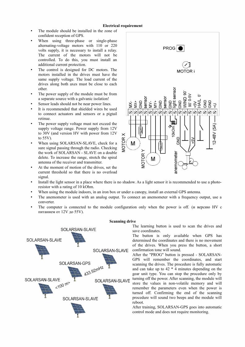
Electrical requirement• The module should be installed in the zone of
confident reception of GPS.• When using three-phase or single-phase
alternating-voltage motors with 110 or 220volts supply, it is necessary to install a relay.The current of the motors will not becontrolled. To do this, you must install anadditional current protection.
• The control is designed for DC motors. Themotors installed in the drives must have thesame supply voltage. The load current of thedrives along both axes must be close to eachother.
• The power supply of the module must be froma separate source with a galvanic isolation!
• Sensor leads should not be near power lines.• It is recommended that shielded wires be used
to connect actuators and sensors or a pigtailretinue.
• The power supply voltage must not exceed thesupply voltage range. Power supply from 12Vto 30V (and version HV with power from 12Vto 55V).
• When using SOLARSAN-SLAVE, check for asure signal passing through the radio. Checkingthe work of SOLARSAN - SLAVE on a doubledelete. To increase the range, stretch the spiralantenna of the receiver and transmitter.
• At the moment of motion of the drives, set thecurrent threshold so that there is no overloadsignal.
• Install the light sensor in a place where there is no shadow. As a light sensor it is recommended to use a photo-resistor with a rating of 10 kOhm.
• When using the module indoors, in an iron box or under a canopy, install an external GPS antenna.• The anemometer is used with an analog output. To connect an anemometer with a frequency output, use a
converter.• The computer is connected to the module configuration only when the power is off. (и версию HV с
питанием от 12V до 55V).
Scanning driveThe learning button is used to scan the drives andsave coordinates.The button is only available when GPS hasdetermined the coordinates and there is no movementof the drives. When you press the button, a shortconfirmation tone will sound.After the "PROG" button is pressed - SOLARSAN-GPS will remember the coordinates, and startscanning the drives. The procedure is fully automaticand can take up to 42 * 4 minutes depending on thegear unit type. You can stop the procedure only byturning off the power. After scanning, the module willstore the values in non-volatile memory and willremember the parameters even when the power isturned off. Confirming the end of the scanningprocedure will sound two beeps and the module willreboot.After training, SOLARSAN-GPS goes into automaticcontrol mode and does not require monitoring.
Principle of operationSOLARSAN informs you at power-up by two beeps about power supply. After that, the motor turns on the azimuth (Xaxis) counterclockwise at dawn. If the motor stopped earlier, it disappears or there is no feedback signal. The sameprocedure is repeated for the axis height (Y axis), the motor will start to set the panel perpendicular to the ground. Thisis the starting position. After determining the data of the satellites, as indicated by the flashing LED, SOLARSAN willset the panel perpendicular to the sun's rays. With each change in the design position of the sun by one degree, thepanels will be pushed to achieve maximum positioning accuracy. This is especially important for parabolicconcentrators. Every minute, data on all calculations and positions are output to the port and transmitted by thetransmitter for SOLARSAN-SLAVE.At the end of the day, when the sun is over the horizon and no protection is activated by the wind or hail sensor, areboot will occur and the panels will be set to the initial position. This is done to prevent snow on the warm panels.In the event that a wind sensor is triggered at night, the panels will move to a position parallel to the ground and remainin this position until dawn.
Setting the current protection threshold The module SOLARSAN-GPS provides several types of protection. In the actuators there are limit switches, themodule always knows in which position the drive is located and will not give the task to move beyond the value, andthere are also two types of current protection - a fuse and an electronic current sensor. The current sensor threshold canbe set with the trimmer resistor "MOTOR i". For convenience of adjustment, for 10% before shutdown, the controlmodule will warn the buzzer. The current threshold is set at the time of travel and is effective for both drives. Therefore,I recommend using drives of the same power.
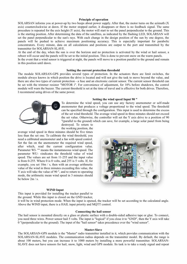
Setting the wind speed Input 90 " To determine the wind speed, you can use any factory anemometer or self-madeanemometer that produces a voltage proportional to the wind speed. The thresholdcan be specified through the configuration. This input is used to determine the excessof the set wind threshold. The average wind speed in three minutes should not exceedthe set value. Otherwise, the controller will set the Y axis drive to a position of 90"(parallel to the ground) which can save, for example, a large solar panel from beingdestroyed. To return tothe working position, the
average wind speed in three minutes should be five timesless than the set one. To calibrate the wind threshold, youneed a calibrated anemometer and a fan with speed control.Set the fan on the anemometer the required wind speed,after which, read the current configuration value.Parameter WI- "" means the instantaneous wind speed. Theparameter WU- «indicates the threshold value of windspeed. The values are set from 11-255 and the input valueis from 0-255. Where 0 is 0 volts, and 255 is 5 volts. If, forexample, you set 10m / s, then with an average arithmeticvalue of the wind in three minutes exceeding this value, theY axis will take the value of 90 ", and to return to operatingmode, the arithmetic mean wind speed in 3 minutes shouldbe below 2m / s.
WIND Input This input is provided for installing the tracker parallel tothe ground. While this input is closed on the GND tracker,it will be in wind protection mode. When the input is opened, the tracker will be set according to the calculated angle.Above the WIND input, there is a HAIL input priority and MQTT control.
Connecting the hail sensor The hail sensor is mounted directly on a glass or plastic surface with a double-sided adhesive tape or glue. To connect,you need three wires. Power sensor hail 5 volts. The input is "logical" if you close it to "GND", then the Y axis will take0 "(perpendicular to the ground). The input of the "hail sensor" takes precedence over the "wind sensor".
Master-Slave The SOLARSAN-GPS module is the "Master" radio transmitter installed in it, which provides communication with theSOLARSAN-SLAVE modules. The communication radius depends on the transmitter model. By default, the range isabout 100 meters, but you can increase it to 1000 meters by installing a more powerful transmitter. SOLARSAN-SLAVE does not have sensors for hail, snow, light, wind and GPS module. Its task is to take a ready signal and repeat
the position. In SOLARSAN-SLAVE the same requirements for installation and installation of the current threshold.The number of SOLARSAN-SLAVE connected to one SOLARSAN-GPS is not limited. The encryption methodprovides reliable protection against interference or interference.
Light sensor It is recommended to use this function, which should reduce the management costs in low light. Set the photo resistor toa place where there is no shadow. The procedure is best done at sunset or sunrise: Wait for the SV- "value" in the data line. Set the value of parameter SP- from 3-255. The value of SP is compared with SV. If SV> SP, then SOLARSAN-GPS falls asleep.
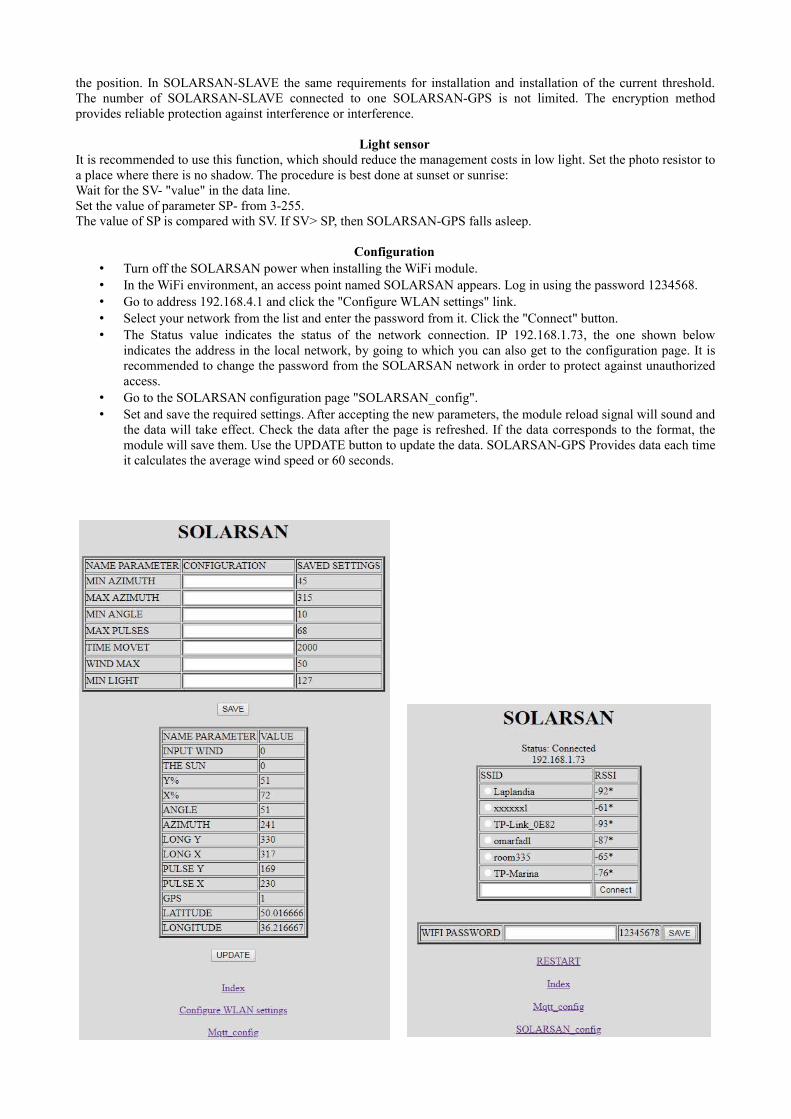
Configuration • Turn off the SOLARSAN power when installing the WiFi module. • In the WiFi environment, an access point named SOLARSAN appears. Log in using the password 1234568.• Go to address 192.168.4.1 and click the "Configure WLAN settings" link.• Select your network from the list and enter the password from it. Click the "Connect" button. • The Status value indicates the status of the network connection. IP 192.168.1.73, the one shown below
indicates the address in the local network, by going to which you can also get to the configuration page. It isrecommended to change the password from the SOLARSAN network in order to protect against unauthorizedaccess.
• Go to the SOLARSAN configuration page "SOLARSAN_config". • Set and save the required settings. After accepting the new parameters, the module reload signal will sound and
the data will take effect. Check the data after the page is refreshed. If the data corresponds to the format, themodule will save them. Use the UPDATE button to update the data. SOLARSAN-GPS Provides data each timeit calculates the average wind speed or 60 seconds.
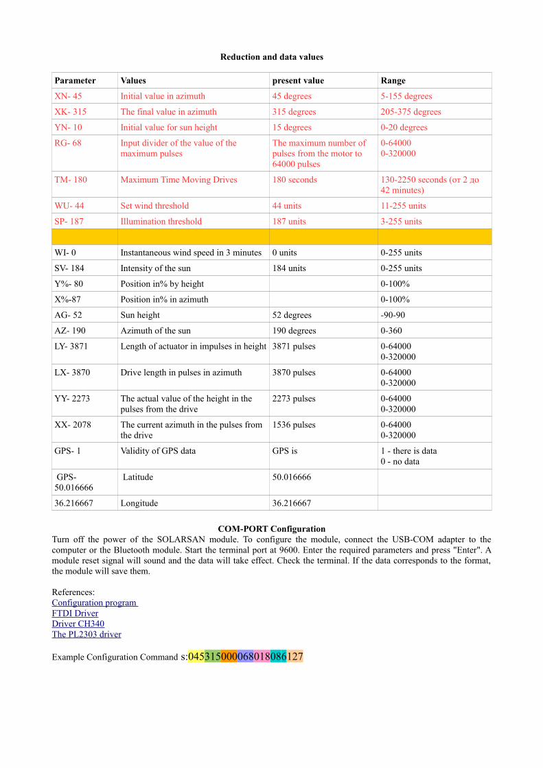
Reduction and data values
Parameter Values present value Range
XN- 45 Initial value in azimuth 45 degrees 5-155 degrees
XK- 315 The final value in azimuth 315 degrees 205-375 degrees
YN- 10 Initial value for sun height 15 degrees 0-20 degrees
RG- 68 Input divider of the value of the maximum pulses
The maximum number of pulses from the motor to 64000 pulses
0-640000-320000
TM- 180 Maximum Time Moving Drives 180 seconds 130-2250 seconds (от 2 до 42 minutes)
WU- 44 Set wind threshold 44 units 11-255 units
SP- 187 Illumination threshold 187 units 3-255 units
WI- 0 Instantaneous wind speed in 3 minutes 0 units 0-255 units
SV- 184 Intensity of the sun 184 units 0-255 units
Y%- 80 Position in% by height 0-100%
X%-87 Position in% in azimuth 0-100%
AG- 52 Sun height 52 degrees -90-90
AZ- 190 Azimuth of the sun 190 degrees 0-360
LY- 3871 Length of actuator in impulses in height 3871 pulses 0-640000-320000
LX- 3870 Drive length in pulses in azimuth 3870 pulses 0-640000-320000
YY- 2273 The actual value of the height in the pulses from the drive
2273 pulses 0-640000-320000
XX- 2078 The current azimuth in the pulses from the drive
1536 pulses 0-640000-320000
GPS- 1 Validity of GPS data GPS is 1 - there is data0 - no data
GPS- 50.016666
Latitude 50.016666
36.216667 Longitude 36.216667
COM-PORT ConfigurationTurn off the power of the SOLARSAN module. To configure the module, connect the USB-COM adapter to thecomputer or the Bluetooth module. Start the terminal port at 9600. Enter the required parameters and press "Enter". Amodule reset signal will sound and the data will take effect. Check the terminal. If the data corresponds to the format,the module will save them.
References:Configuration program FTDI DriverDriver CH340The PL2303 driver
Example Configuration Command s:045315000068018086127

Parameter Variabletype
Range Description
s: ID config start of package
045 XN 005 to 155 Initial value in azimuth
315 XK 205 to 375 The final value in azimuth
010 YN 000 to 020 Initial value for sun height
068 GR Input divisor067 and 068
Input divider of the value of the maximum pulsesWith a value of 067, there are 320000 imps.With a value of 068, there are 64000 imps.
018 TM Travel timefrom 013 to 255
Maximum drive travel timefrom 130 to 2550 seconds (from 2 to 42 minutes)
086 WU Wind speed threshold011 to 250
The value is set from 11-250where 0 is zero volts 255 - 5 voltsIt is set on the basis of the parameterWI - instantaneous wind speedIf WI> WU, then the panel will become parallelto the ground.
127 SP Illumination thresholdFrom 003 to 255
The value is set from 3-255where 0 is zero volts 255 - 5 voltsThe value of SP is compared with SV.If SV> SP then SOLARSAN-GPS falls asleep

Telemetry MQTT
To configure remote management and telemetry, you need to connect to the MQTT server.
for example https:// cloudmqtt.com. Application for ANDROID and IOS
• To do this, you need to register and get the data SERVER, LOGIN, PASSWORD, PORT.
• Enter this information in the appropriate sections. Install the MQTT client application and enter the same data.
Select Port
Connect
Configuration string
Send data
XN- 45 XK- 315 YN- 10 RG- 67 TM- 2000 WU- 50 SP- 220 WI- 0 SV- 0 Y%- 64 X%- 46 AG- 62 AZ- 170 LY- 327 LX- 550 YY- 212 XX- 254 GPS- 50.016666 36.216667 GPS- 1
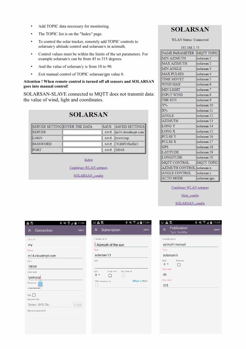
• Add TOPIC data necessary for monitoring.
• The TOPIC list is on the "Index" page.
• To control the solar tracker, remotely add TOPIC controls tosolarsan/y altitude control and solarsan/x in azimuth.
• Control values must be within the limits of the set parameters. Forexample solarsan/x can be from 45 to 315 degrees.
• And the value of solarsan/y is from 10 to 90.
• Exit manual control of TOPIC solarsan/gps value 0.
Attention ! When remote control is turned off all sensors and SOLARSANgoes into manual control!
SOLARSAN-SLAVE connected to MQTT does not transmit data:the value of wind, light and coordinates.
Azimuth of the sun