az750602.vo.msecnd.net solid concrete ground based floors insulation below the floor slab figure 6...
TRANSCRIPT

INSULATION FOR SOLID CONCRETE AND SUSPENDEDGROUND FLOORS
CI/Sfb
Seventh Issue November 2014
(27.9) Rn7 M2
TF70
● High performance rigidthermoset insulation – thermalconductivity 0.022 W/m.K
● Can reduce the cost of related items – soil removal,service connections
● Unaffected by air infiltration
● Resistant to the passage ofwater vapour
● Easy to handle and install
● Ideal for new build andrefurbishment
● Non–deleterious material
● Manufactured with a blowingagent that has zero ODP andlow GWP
I nsu la t ion
Low Energy –Low Carbon Buildings
2
Typical Constructions and U–values
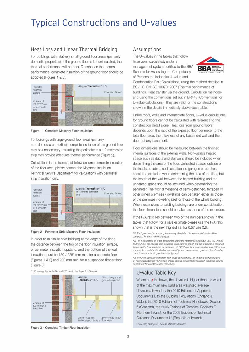
Heat Loss and Linear Thermal BridgingFor buildings with relatively small ground floor areas (primarilydomestic properties), if the ground floor is left uninsulated, thethermal performance will be poor. To enhance the thermalperformance, complete insulation of the ground floor should beadopted (Figures 1 & 3).
KingspanThermafloor® TF70in 1.2 metre perimeterstrip
Figure 2 – Perimeter Strip Masonry Floor Insulation
Figure 1 – Complete Masonry Floor Insulation
For buildings with large ground floor areas (primarilynon–domestic properties), complete insulation of the ground floormay be unnecessary. Insulating the perimeter in a 1.2 metre widestrip may provide adequate thermal performance (Figure 2).
Calculations in the tables that follow assume complete insulationof the floor area, please contact the Kingspan InsulationTechnical Service Department for calculations with perimeterstrip insulation only.
Perimeter insulation upstand
Minimum of 150 / 225* mm for a concretefloor
Figure 3 – Complete Timber Floor Insulation
KingspanThermafloor® TF70
Minimum of 200 mm for atimber floor
25 mm x 25 mmtimber support battens
18 mm tongue andgrooved chipboard
50 mm wide timberfloor joists
Floor slab
KingspanThermafloor® TF70
Screed
Floor slab Screed
Perimeter insulation upstand
Minimum of 150 / 225* mm for a concretefloor
AssumptionsThe U−values in the tables that followhave been calculated, under amanagement system certified to the BBAScheme for Assessing the Competencyof Persons to Undertake U–value andCondensation Risk Calculations, using the method detailed inBS / I.S. EN ISO 13370: 2007 (Thermal performance ofbuildings. Heat transfer via the ground. Calculation methods)and using the conventions set out in BR443 (Conventions forU–value calculations). They are valid for the constructionsshown in the details immediately above each table.
Unlike roofs, walls and intermediate floors, U–value calculationsfor ground floors cannot be calculated with reference to theconstruction detail alone. Heat loss from ground floorsdepends upon the ratio of the exposed floor perimeter to thetotal floor area, the thickness of any basement wall and thedepth of any basement.
Floor dimensions should be measured between the finishedinternal surfaces of the external walls. Non–usable heatedspace such as ducts and stairwells should be included whendetermining the area of the floor. Unheated spaces outside ofthe insulated fabric, such as attached garages or porches,should be excluded when determining the area of the floor, butthe length of the wall between the heated building and theunheated space should be included when determining theperimeter. The floor dimensions of semi–detached, terraced orother joined premises / dwellings can be taken either as thoseof the premises / dwelling itself or those of the whole building.Where extensions to existing buildings are under consideration,the floor dimensions should be taken as those of the extension.
If the P/A ratio lies between two of the numbers shown in thetables that follow, for a safe estimate please use the P/A ratioshown that is the next highest i.e. for 0.57 use 0.6.NB The figures quoted are for guidance only. A detailed U–value calculation should becompleted for each individual project.
NB For the purposes of these calculations, using the method as detailed in BS / I.S. EN ISO13370: 2007, the soil has been assumed to be sand or gravel, the wall insulation is assumedto overlap the floor insulation by minimum 150 / 225* mm for a concrete floor and 200 mm fora timber floor, and the standard of workmanship has been assumed good and therefore thecorrection factor for air gaps has been ignored.
NB If your construction is different from those specified and / or to gain a comprehensiveU–value calculation for your project please consult the Kingspan Insulation Technical ServiceDepartment for assistance (see rear cover).
U–value Table KeyWhere an 7 is shown, the U–value is higher than the worstof the maximum new build area weighted averageU–values allowed by the 2010 Editions of ApprovedDocuments L to the Building Regulations (England &Wales), the 2010 Editions of Technical Handbooks Section6 (Scotland), the 2006 Editions of Technical Booklets F(Northern Ireland), or the 2008 Editions of TechnicalGuidance Documents L* (Republic of Ireland).
* Excluding Change of Use and Material Alterations.
In order to minimise cold bridging at the edge of the floor, the distance between the top of the floor insulation surface, or perimeter insulation upstand, and the bottom of the wallinsulation must be 150 / 225* mm min. for a concrete floor(Figures 1 & 2) and 200 mm min. for a suspended timber floor(Figure 3).
* 150 mm applies to the UK and 225 mm to the Republic of Ireland.
3
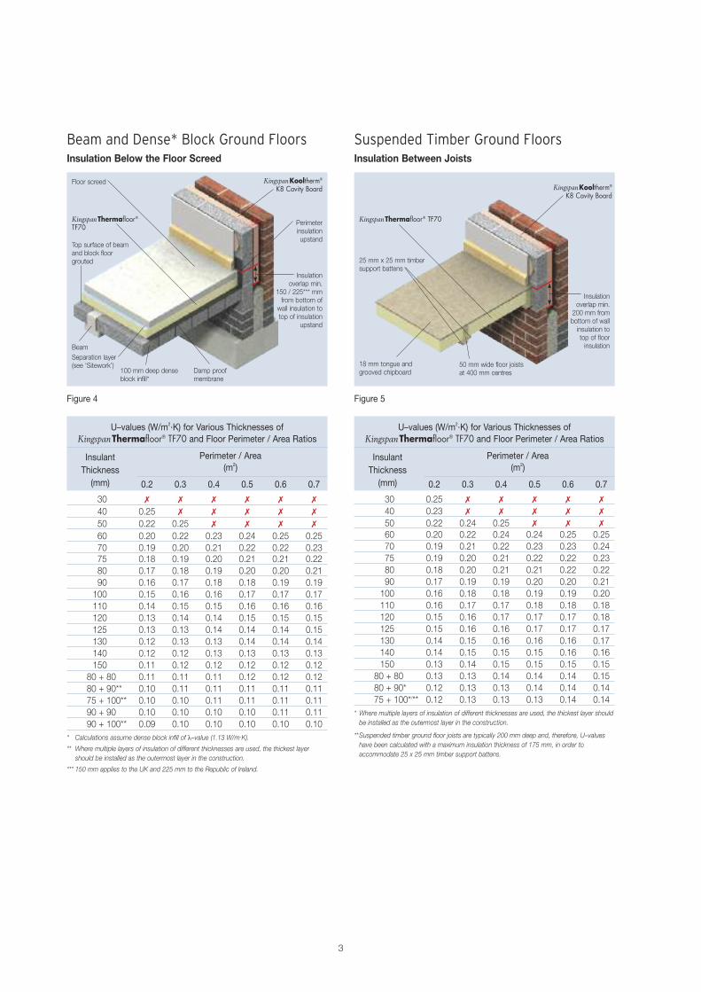
Beam and Dense* Block Ground FloorsInsulation Below the Floor Screed
Figure 4
Top surface of beam and block floorgrouted
Perimeterinsulationupstand
Floor screed KingspanKooltherm®
K8 Cavity Board
BeamSeparation layer(see ‘Sitework’)
100 mm deep denseblock infill*
Damp proofmembrane
Insulationoverlap min.
150 / 225*** mmfrom bottom ofwall insulation totop of insulation
upstand
KingspanThermafloor®TF70
U–values (W/m2.K) for Various Thicknesses ofKingspanThermafloor® TF70 and Floor Perimeter / Area Ratios
Perimeter / Area (m2)
0.2 0.3 0.4 0.5 0.6 0.7
30 0.25 7 7 7 7 7
40 0.23 7 7 7 7 7
50 0.22 0.24 0.25 7 7 7
60 0.20 0.22 0.24 0.24 0.25 0.2570 0.19 0.21 0.22 0.23 0.23 0.2475 0.19 0.20 0.21 0.22 0.22 0.2380 0.18 0.20 0.21 0.21 0.22 0.2290 0.17 0.19 0.19 0.20 0.20 0.21100 0.16 0.18 0.18 0.19 0.19 0.20110 0.16 0.17 0.17 0.18 0.18 0.18120 0.15 0.16 0.17 0.17 0.17 0.18125 0.15 0.16 0.16 0.17 0.17 0.17130 0.14 0.15 0.16 0.16 0.16 0.17140 0.14 0.15 0.15 0.15 0.16 0.16150 0.13 0.14 0.15 0.15 0.15 0.15
80 + 80 0.13 0.13 0.14 0.14 0.14 0.1580 + 90* 0.12 0.13 0.13 0.14 0.14 0.1475 + 100*/** 0.12 0.13 0.13 0.13 0.14 0.14
* Where multiple layers of insulation of different thicknesses are used, the thickest layer shouldbe installed as the outermost layer in the construction.
**Suspended timber ground floor joists are typically 200 mm deep and, therefore, U–valueshave been calculated with a maximum insulation thickness of 175 mm, in order toaccommodate 25 x 25 mm timber support battens.
Figure 5
Suspended Timber Ground FloorsInsulation Between Joists
25 mm x 25 mm timbersupport battens
18 mm tongue andgrooved chipboard
50 mm wide floor joistsat 400 mm centres
KingspanKooltherm®
K8 Cavity Board
KingspanThermafloor® TF70
Insulationoverlap min.200 mm frombottom of wallinsulation totop of floorinsulation
U–values (W/m2.K) for Various Thicknesses ofKingspanThermafloor® TF70 and Floor Perimeter / Area Ratios
Perimeter / Area (m2)
0.2 0.3 0.4 0.5 0.6 0.7
30 7 7 7 7 7 7
40 0.25 7 7 7 7 7
50 0.22 0.25 7 7 7 7
60 0.20 0.22 0.23 0.24 0.25 0.2570 0.19 0.20 0.21 0.22 0.22 0.2375 0.18 0.19 0.20 0.21 0.21 0.2280 0.17 0.18 0.19 0.20 0.20 0.2190 0.16 0.17 0.18 0.18 0.19 0.19100 0.15 0.16 0.16 0.17 0.17 0.17110 0.14 0.15 0.15 0.16 0.16 0.16120 0.13 0.14 0.14 0.15 0.15 0.15125 0.13 0.13 0.14 0.14 0.14 0.15130 0.12 0.13 0.13 0.14 0.14 0.14140 0.12 0.12 0.13 0.13 0.13 0.13150 0.11 0.12 0.12 0.12 0.12 0.12
80 + 80 0.11 0.11 0.11 0.12 0.12 0.1280 + 90** 0.10 0.11 0.11 0.11 0.11 0.1175 + 100** 0.10 0.10 0.11 0.11 0.11 0.1190 + 90 0.10 0.10 0.10 0.10 0.11 0.1190 + 100** 0.09 0.10 0.10 0.10 0.10 0.10
* Calculations assume dense block infill of λ–value (1.13 W/m.K).
** Where multiple layers of insulation of different thicknesses are used, the thickest layer should be installed as the outermost layer in the construction.
*** 150 mm applies to the UK and 225 mm to the Republic of Ireland.
InsulantThickness(mm)
InsulantThickness(mm)
4
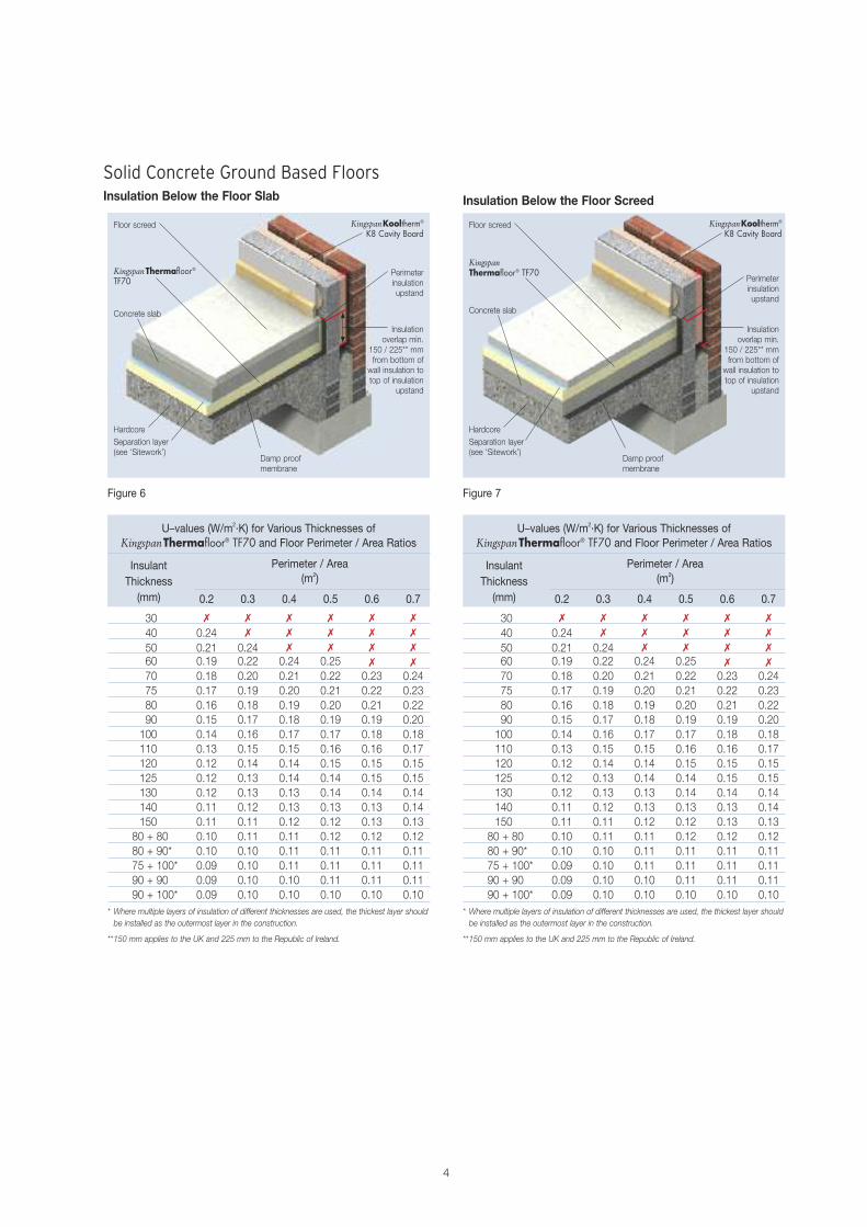
Solid Concrete Ground Based FloorsInsulation Below the Floor Slab
Figure 6
Concrete slab
Floor screed KingspanKooltherm®
K8 Cavity Board
HardcoreSeparation layer(see ‘Sitework’)
KingspanThermafloor®TF70
Perimeterinsulationupstand
Damp proofmembrane
Insulationoverlap min.
150 / 225** mmfrom bottom ofwall insulation totop of insulation
upstand
Insulation Below the Floor Screed
U–values (W/m2.K) for Various Thicknesses ofKingspanThermafloor® TF70 and Floor Perimeter / Area Ratios
Perimeter / Area (m2)
0.2 0.3 0.4 0.5 0.6 0.7
30 7 7 7 7 7 7
40 0.24 7 7 7 7 7
50 0.21 0.24 7 7 7 7
60 0.19 0.22 0.24 0.25 7 7
70 0.18 0.20 0.21 0.22 0.23 0.2475 0.17 0.19 0.20 0.21 0.22 0.2380 0.16 0.18 0.19 0.20 0.21 0.2290 0.15 0.17 0.18 0.19 0.19 0.20100 0.14 0.16 0.17 0.17 0.18 0.18110 0.13 0.15 0.15 0.16 0.16 0.17120 0.12 0.14 0.14 0.15 0.15 0.15125 0.12 0.13 0.14 0.14 0.15 0.15130 0.12 0.13 0.13 0.14 0.14 0.14140 0.11 0.12 0.13 0.13 0.13 0.14150 0.11 0.11 0.12 0.12 0.13 0.13
80 + 80 0.10 0.11 0.11 0.12 0.12 0.1280 + 90* 0.10 0.10 0.11 0.11 0.11 0.1175 + 100* 0.09 0.10 0.11 0.11 0.11 0.1190 + 90 0.09 0.10 0.10 0.11 0.11 0.1190 + 100* 0.09 0.10 0.10 0.10 0.10 0.10
* Where multiple layers of insulation of different thicknesses are used, the thickest layer shouldbe installed as the outermost layer in the construction.
**150 mm applies to the UK and 225 mm to the Republic of Ireland.
Figure 7
U–values (W/m2.K) for Various Thicknesses ofKingspanThermafloor® TF70 and Floor Perimeter / Area Ratios
Perimeter / Area (m2)
0.2 0.3 0.4 0.5 0.6 0.7
30 7 7 7 7 7 7
40 0.24 7 7 7 7 7
50 0.21 0.24 7 7 7 7
60 0.19 0.22 0.24 0.25 7 7
70 0.18 0.20 0.21 0.22 0.23 0.2475 0.17 0.19 0.20 0.21 0.22 0.2380 0.16 0.18 0.19 0.20 0.21 0.2290 0.15 0.17 0.18 0.19 0.19 0.20100 0.14 0.16 0.17 0.17 0.18 0.18110 0.13 0.15 0.15 0.16 0.16 0.17120 0.12 0.14 0.14 0.15 0.15 0.15125 0.12 0.13 0.14 0.14 0.15 0.15130 0.12 0.13 0.13 0.14 0.14 0.14140 0.11 0.12 0.13 0.13 0.13 0.14150 0.11 0.11 0.12 0.12 0.13 0.13
80 + 80 0.10 0.11 0.11 0.12 0.12 0.1280 + 90* 0.10 0.10 0.11 0.11 0.11 0.1175 + 100* 0.09 0.10 0.11 0.11 0.11 0.1190 + 90 0.09 0.10 0.10 0.11 0.11 0.1190 + 100* 0.09 0.10 0.10 0.10 0.10 0.10
* Where multiple layers of insulation of different thicknesses are used, the thickest layer shouldbe installed as the outermost layer in the construction.
**150 mm applies to the UK and 225 mm to the Republic of Ireland.
Concrete slab
Floor screed KingspanKooltherm®
K8 Cavity Board
HardcoreSeparation layer(see ‘Sitework’)
KingspanThermafloor® TF70
Perimeterinsulationupstand
Damp proofmembrane
Insulationoverlap min.
150 / 225** mmfrom bottom ofwall insulation totop of insulation
upstand
InsulantThickness(mm)
InsulantThickness(mm)
5
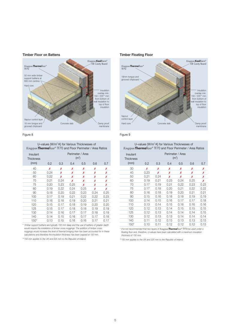
U–values (W/m2.K) for Various Thicknesses ofKingspanThermafloor® TF70 and Floor Perimeter / Area Ratios
Perimeter / Area (m2)
0.2 0.3 0.4 0.5 0.6 0.7
40 7 7 7 7 7 7
50 0.24 7 7 7 7 7
60 0.22 7 7 7 7 7
70 0.21 0.24 7 7 7 7
75 0.20 0.23 0.25 7 7 7
80 0.19 0.22 0.24 0.25 7 7
90 0.18 0.20 0.22 0.23 0.24 0.25100 0.17 0.19 0.21 0.22 0.22 0.23110 0.16 0.18 0.19 0.20 0.21 0.21120 0.15 0.17 0.18 0.19 0.20 0.20125 0.15 0.17 0.18 0.18 0.19 0.19130 0.14 0.16 0.17 0.17 0.18 0.19140 0.14 0.15 0.16 0.17 0.17 0.18150* 0.13 0.15 0.16 0.16 0.17 0.17
* Timber support battens are typically 150 mm deep and the use of battens of greater depthwould require the installation of timber cross noggings. The addition of timber crossnoggings would increase the level of thermal bridging than has been accounted for in thesecalculations and therefore the insulation thickness has been capped at 150 mm.
**150 mm applies to the UK and 225 mm to the Republic of Ireland.
U–values (W/m2.K) for Various Thicknesses ofKingspanThermafloor® TF70 and Floor Perimeter / Area Ratios
Perimeter / Area (m2)
0.2 0.3 0.4 0.5 0.6 0.7
30 7 7 7 7 7 7
40 0.23 7 7 7 7 7
50 0.21 0.24 7 7 7 7
60 0.19 0.21 0.23 0.24 0.25 7
70 0.17 0.19 0.21 0.22 0.23 0.2375 0.17 0.18 0.20 0.21 0.22 0.2280 0.16 0.18 0.19 0.20 0.21 0.2190 0.15 0.16 0.18 0.18 0.19 0.19100 0.14 0.15 0.16 0.17 0.17 0.18110 0.13 0.14 0.15 0.16 0.16 0.16120 0.12 0.13 0.14 0.15 0.15 0.15125 0.12 0.13 0.14 0.14 0.14 0.15130 0.12 0.13 0.13 0.14 0.14 0.14140 0.11 0.12 0.13 0.13 0.13 0.13150* 0.10 0.11 0.12 0.12 0.12 0.13
* It is not recommended that two layers of KingspanThermafloor® TF70 be used under afloating floor and, therefore, U–values have been calculated with a maximum insulationthickness of 150 mm.
**150 mm applies to the UK and 225 mm to the Republic of Ireland.
Figure 9
Timber Floor on Battens Timber Floating Floor
Figure 8
Hard core
18mm tongue andgrooved chipboard
50 mm wide timbersupport battens at 600 mm centres
Hard core
Vapour control layerVapour control layer
KingspanKooltherm®
K8 Cavity BoardKingspanKooltherm®
K8 Cavity BoardKingspanThermafloor®TF70
KingspanThermafloor®TF70
18 mm tongue andgrooved chipboard
Damp proof membrane
Concrete slab Concrete slab Damp proof membrane
Insulation overlap min.
150 / 225** mmfrom bottom ofwall insulation to
top of floorinsulation
Insulation overlap min.
150 / 225** mmfrom bottom ofwall insulation to
top of floorinsulation
InsulantThickness(mm)
InsulantThickness(mm)

6
Environmental Impact & Responsible SourcingGreen Guide RatingAn Ecoprofile, certified by BRE Certification to the 2008 BREEnvironmental Profiles Methodology, has been created forKingspan Thermafloor® TF70 produced at Kingspan Insulation’sBritish manufacturing facilities. The BRE has assigned theproduct a 2008 Green Guide Summary Rating of A+.
Responsible SourcingKingspan Thermafloor® TF70 is manufactured undera management system certified to BS / I.S. EN ISO 14001:2004. The principle polymer components of the product arealso manufactured under management systems certified toISO 14001: 2004.NB The above information is correct at the time of writing. Please confirm at the point of needby contacting Kingspan Insulation’s Technical Service Department (see rear cover), from whichcopies of Kingspan Insulation and its suppliers’ ISO 14001 certificates can be obtained alongwith confirmation of Kingspan Insulation’s products’ Green Guide ratings.
Sustainability & ResponsibilityKingspan Insulation has a long–term commitment tosustainability and responsibility: as a manufacturer and supplierof insulation products; as an employer; as a substantiallandholder; and as a key member of its neighbouringcommunities.
A report covering the sustainability and responsibility ofKingspan Insulation Ltd’s British operations is available atwww.kingspaninsulation.co.uk/sustainabilityandresponsibility.
Specification ClauseKingspan Thermafloor® TF70 should be described inspecifications as:–
The floor insulation shall be Kingspan Thermafloor® TF70____ mm thick: comprising a high performance rigid thermosetinsulation core faced on both sides with a low emissivitycomposite foil facing. The product shall be manufactured: with a blowing agent that has zero Ozone Depletion Potential(ODP) and low Global Warming Potential (GWP); in accordancewith the requirements of BS 4841–6; under a managementsystem certified to BS / I.S. EN ISO 9001: 2008, BS / I.S. ENISO 14001: 2004 and BS / I.S. OHSAS 18001: 2007; byKingspan Insulation Limited; and installed in accordance withthe instructions issued by them.
NBS SpecificationsDetails also available in NBS Plus.NBS users should refer to clause(s): E20 200, K11 115, 125, 135, 145, 215, 225,235, 245, M10 290, M13 260 and P10 255(Standard and Intermediate) E20 30 (Minor Works)
Design StandardsConsideration should be given to the recommendations of BS 8102: 1990 (Code of practice for protection of buildingsagainst water from the ground), BS 8215: 1991 (Code ofpractice for design and installation of damp proof courses inmasonry construction), and the information given in BuildingResearch Establishment Digest 104 (Floor Screeds).
Compressive LoadsUn–reinforced floor screeds can be used in conjunction withKingspan Thermafloor® TF70 in most applications. Thecompressive strength of Kingspan Thermafloor® TF70 offersconsiderable advantages over some other floor insulants.Providing a minimum compressive strength of 140 kPa at 10%compression allows greater floor loads to be considered andtherefore additional scope in the use of KingspanThermafloor® TF70. However, where floor loads are to beexcessive, consideration should be given to the use ofKingspan Styrozone® extruded polystyrene insulation whichhas greater compressive strength. For further informationplease contact the Kingspan Insulation Technical ServiceDepartment (see rear cover).
SubstrateKingspan Thermafloor® TF70 is not recommended for use indirect contact with subsoil and must be used over a DPM.
Lightning ProtectionBuilding designers should give consideration to therequirements of BS / I.S. EN 62305: 2006 (Protection againstlightning).
Design Considerations
Environmental Profiles SchemeCertificate Number ENP 409
7
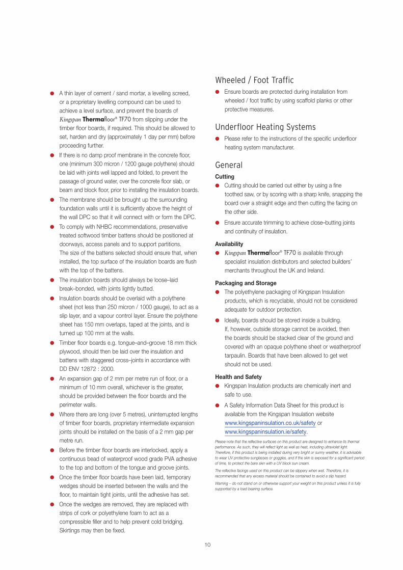
Underfloor heating systems can also be accommodated insuspended timber floors. This arrangement has low thermalmass and so is more suited to intermittent heating cycleapplications (Figure 14).
Figure 14 – Intermittent Heating Applications –Suspended Timber Floor
Heating pipes
Sand / cement filling
Separation layer of polythenesheet (not less than 125 micron/ 500 gauge)
18 mm plywood
Support battens
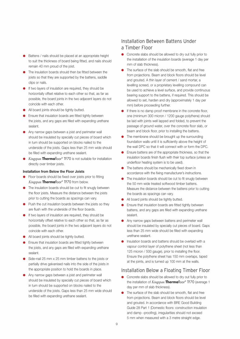
Figure 13 – Intermittent Heating Applications –Beam and Block Floor
Heating pipes
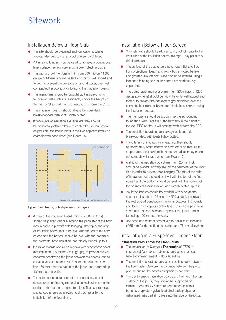
For intermittent heating applications, where a fast responsetime is required, it is beneficial to have less thermal massavailable to take up heat from the system and so placing theinsulation layer below the screed (Figure 11) or timber floor(Figure 12) but above the concrete slab or beam and blockfloor (Figure 13) is the best solution.
Figure 11 – Intermittent Heating Applications –Below the Floor Screed
Heating pipes
Figure 12 – Intermittent Heating Applications – Timber Floor on Battens
Heating pipes
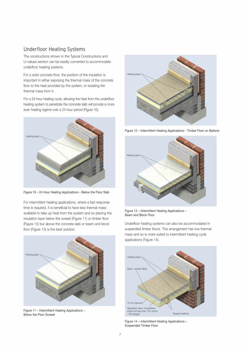
Figure 10 – 24 Hour Heating Applications – Below the Floor Slab
Underfloor Heating SystemsThe constructions shown in the Typical Constructions andU–values section can be readily converted to accommodateunderfloor heating systems.
For a solid concrete floor, the position of the insulation isimportant in either exposing the thermal mass of the concretefloor to the heat provided by the system, or isolating thethermal mass from it.
For a 24 hour heating cycle, allowing the heat from the underfloorheating system to penetrate the concrete slab will provide a moreeven heating regime over a 24 hour period (Figure 10).
Heating pipes
Installation Below a Floor Screed● Concrete slabs should be allowed to dry out fully prior to the
installation of the insulation boards (average 1 day per mm ofslab thickness).
● The surface of the slab should be smooth, flat and freefrom projections. Beam and block floors should be leveland grouted. Rough cast slabs should be levelled using athin sand blinding to ensure boards are continuouslysupported.
● The damp proof membrane (minimum 300 micron / 1200gauge polythene) should be laid with joints well lapped andfolded, to prevent the passage of ground water, over theconcrete floor slab, or beam and block floor, prior to layingthe insulation boards.
● The membrane should be brought up the surroundingfoundation walls until it is sufficiently above the height ofthe wall DPC so that it will connect with or form the DPC.
● The insulation boards should always be loose–laidbreak–bonded, with joints lightly butted.
● If two layers of insulation are required, they should be horizontally offset relative to each other so that, as faras possible, the board joints in the two adjacent layers donot coincide with each other (see Figure 15).
● A strip of the insulation board (minimum 20mm thick)should be placed vertically around the perimeter of the floorslab in order to prevent cold bridging. The top of the stripof insulation board should be level with the top of the floorscreed and the bottom should be level with the bottom ofthe horizontal floor insulation, and closely butted up to it.
● Insulation boards should be overlaid with a polythenesheet (not less than 125 micron / 500 gauge), to preventthe wet screed penetrating the joints between the boards,and to act as a vapour control layer. Ensure the polythenesheet has 150 mm overlaps, taped at the joints, and isturned up 100 mm at the walls.
● Use sand and cement screed laid to a minimum thicknessof 65 mm for domestic construction and 75 mm elsewhere.
Installation in a Suspended Timber FloorInstallation from Above the Floor Joists● The installation of Kingspan Thermafloor® TF70 in
suspended floor constructions should be carried outbefore commencement of floor boarding.
● The insulation boards should be cut to fit snugly betweenthe floor joists. Measure the distance between the joistsprior to cutting the boards as spacings can vary.
● In order to ensure insulation boards are flush with the topsurface of the joists, they should be supported onmiminum 25 mm x 25 mm treated softwood timberbattens, proprietary galvanised steel saddle clips, orgalvanised nails partially driven into the side of the joists.
● A strip of the insulation board (minimum 20mm thick)should be placed vertically around the perimeter of the floorslab in order to prevent cold bridging. The top of the stripof insulation board should be level with the top of the floorscreed and the bottom should be level with the bottom ofthe horizontal floor insulation, and closely butted up to it.
● Insulation boards should be overlaid with a polythene sheet(not less than 125 micron / 500 gauge), to prevent the wetconcrete penetrating the joints between the boards, and toact as a vapour control layer. Ensure the polythene sheethas 150 mm overlaps, taped at the joints, and is turned up100 mm at the walls.
● The subsequent installation of the concrete slab andscreed or other flooring material is carried out in a mannersimilar to that for an un–insulated floor. The concrete slaband screed should be allowed to dry out prior to theinstallation of the floor finish.
Installation Below a Floor Slab● The site should be prepared and foundations, where
appropriate, built to damp proof course (DPC) level.
● A thin sand blinding may be used to achieve a continuouslevel surface free from projections over rolled hardcore.
● The damp proof membrane (minimum 300 micron / 1200gauge polythene) should be laid with joints well lapped andfolded, to prevent the passage of ground water, over wellcompacted hardcore, prior to laying the insulation boards.
● The membrane should be brought up the surroundingfoundation walls until it is sufficiently above the height ofthe wall DPC so that it will connect with or form the DPC.
● The insulation boards should always be loose–laidbreak–bonded, with joints lightly butted.
● If two layers of insulation are required, they should be horizontally offset relative to each other so that, as faras possible, the board joints in the two adjacent layers docoincide with each other (see Figure 15).
8
Sitework
Figure 15 – Offsetting of Multiple Insulation Layers
First insulation layer
Second insulation layer, if required, offset relative to first.
Installation Between Battens Undera Timber Floor● Concrete slabs should be allowed to dry out fully prior to
the installation of the insulation boards (average 1 day permm of slab thickness).
● The surface of the slab should be smooth, flat and freefrom projections. Beam and block floors should be leveland grouted. A thin layer of cement / sand mortar, alevelling screed, or a proprietary levelling compound canbe used to achieve a level surface, and provide continuousbearing support to the battens, if required. This should beallowed to set, harden and dry (approximately 1 day permm) before proceeding further.
● If there is no damp proof membrane in the concrete floor,one (minimum 300 micron / 1200 gauge polythene) shouldbe laid with joints well lapped and folded, to prevent thepassage of ground water, over the concrete floor slab, orbeam and block floor, prior to installing the battens.
● The membrane should be brought up the surroundingfoundation walls until it is sufficiently above the height ofthe wall DPC so that it will connect with or form the DPC.
● Ensure battens are of the appropriate thickness, so that theinsulation boards finish flush with their top surface (unless anunderfloor heating system is to be used).
● The battens should be mechanically fixed down inaccordance with the fixing manufacturer’s instructions.
● The insulation boards should be cut to fit snugly betweenthe 50 mm wide treated softwood timber battens.Measure the distance between the battens prior to cuttingthe boards as spacings can vary.
● All board joints should be tightly butted.
● Ensure that insulation boards are fitted tightly betweenbattens, and any gaps are filled with expanding urethanesealant.
● Any narrow gaps between battens and perimeter wallshould be insulated by specially cut pieces of board. Gapsless than 25 mm wide should be filled with expandingurethane sealant.
● Insulation boards and battens should be overlaid with avapour control layer of polythene sheet (not less than 125 micron / 500 gauge), prior to installing the floor.Ensure the polythene sheet has 150 mm overlaps, tapedat the joints, and is turned up 100 mm at the walls.
Installation Below a Floating Timber Floor● Concrete slabs should be allowed to dry out fully prior to
the installation of Kingspan Thermafloor® TF70 (average 1day per mm of slab thickness).
● The surface of the slab should be smooth, flat and freefrom projections. Beam and block floors should be leveland grouted. In accordance with BRE Good BuildingGuide 28 Part 1 (Domestic floors: construction insulationand damp –proofing), irregularities should not exceed 5 mm when measured with a 3 metre straight edge.
● Battens / nails should be placed at an appropriate heightto suit the thickness of board being fitted, and nails shouldremain 40 mm proud of the joist.
● The insulation boards should then be fitted between thejoists so that they are supported by the battens, saddleclips or nails.
● If two layers of insulation are required, they should behorizontally offset relative to each other so that, as far aspossible, the board joints in the two adjacent layers do notcoincide with each other.
● All board joints should be tightly butted.
● Ensure that insulation boards are fitted tightly between the joists, and any gaps are filled with expanding urethanesealant.
● Any narrow gaps between a joist and perimeter wallshould be insulated by specially cut pieces of board whichin turn should be supported on blocks nailed to theunderside of the joists. Gaps less than 25 mm wide shouldbe filled with expanding urethane sealant.
● Kingspan Thermafloor® TF70 is not suitable for installationdirectly over timber joists.
Installation from Below the Floor Joists● Floor boards should be fixed over joists prior to fitting
Kingspan Thermafloor® TF70 from below. ● The insulation boards should be cut to fit snugly between
the floor joists. Measure the distance between the joistsprior to cutting the boards as spacings can vary.
● Push the cut insulation boards between the joists so theyare flush with the underside of the floor boards.
● If two layers of insulation are required, they should behorizontally offset relative to each other so that, as far aspossible, the board joints in the two adjacent layers do notcoincide with each other.
● All board joints should be tightly butted.
● Ensure that insulation boards are fitted tightly between the joists, and any gaps are filled with expanding urethanesealant.
● Side–nail 25 mm x 25 mm timber battens to the joists orpartially drive galvanised nails into the side of the joists inthe appropriate position to hold the boards in place.
● Any narrow gaps between a joist and perimeter wallshould be insulated by specially cut pieces of board whichin turn should be supported on blocks nailed to theunderside of the joists. Gaps less than 25 mm wide shouldbe filled with expanding urethane sealant.
9
● A thin layer of cement / sand mortar, a levelling screed, or a proprietary levelling compound can be used toachieve a level surface, and prevent the boards ofKingspan Thermafloor® TF70 from slipping under thetimber floor boards, if required. This should be allowed toset, harden and dry (approximately 1 day per mm) beforeproceeding further.
● If there is no damp proof membrane in the concrete floor,one (minimum 300 micron / 1200 gauge polythene) shouldbe laid with joints well lapped and folded, to prevent thepassage of ground water, over the concrete floor slab, orbeam and block floor, prior to installing the insulation boards.
● The membrane should be brought up the surroundingfoundation walls until it is sufficiently above the height ofthe wall DPC so that it will connect with or form the DPC.
● To comply with NHBC recommendations, preservativetreated softwood timber battens should be positioned atdoorways, access panels and to support partitions. The size of the battens selected should ensure that, wheninstalled, the top surface of the insulation boards are flushwith the top of the battens.
● The insulation boards should always be loose–laidbreak–bonded, with joints lightly butted.
● Insulation boards should be overlaid with a polythenesheet (not less than 250 micron / 1000 gauge), to act as aslip layer, and a vapour control layer. Ensure the polythenesheet has 150 mm overlaps, taped at the joints, and isturned up 100 mm at the walls.
● Timber floor boards e.g. tongue–and–groove 18 mm thickplywood, should then be laid over the insulation andbattens with staggered cross–joints in accordance with DD ENV 12872 : 2000.
● An expansion gap of 2 mm per metre run of floor, or aminimum of 10 mm overall, whichever is the greater,should be provided between the floor boards and theperimeter walls.
● Where there are long (over 5 metres), uninterrupted lengthsof timber floor boards, proprietary intermediate expansionjoints should be installed on the basis of a 2 mm gap permetre run.
● Before the timber floor boards are interlocked, apply acontinuous bead of waterproof wood grade PVA adhesiveto the top and bottom of the tongue and groove joints.
● Once the timber floor boards have been laid, temporarywedges should be inserted between the walls and thefloor, to maintain tight joints, until the adhesive has set.
● Once the wedges are removed, they are replaced withstrips of cork or polyethylene foam to act as acompressible filler and to help prevent cold bridging.Skirtings may then be fixed.
Wheeled / Foot Traffic● Ensure boards are protected during installation from
wheeled / foot traffic by using scaffold planks or otherprotective measures.
Underfloor Heating Systems● Please refer to the instructions of the specific underfloor
heating system manufacturer.
GeneralCutting● Cutting should be carried out either by using a fine
toothed saw, or by scoring with a sharp knife, snapping theboard over a straight edge and then cutting the facing onthe other side.
● Ensure accurate trimming to achieve close–butting jointsand continuity of insulation.
Availability● Kingspan Thermafloor® TF70 is available through
specialist insulation distributors and selected builders’merchants throughout the UK and Ireland.
Packaging and Storage● The polyethylene packaging of Kingspan Insulation
products, which is recyclable, should not be consideredadequate for outdoor protection.
● Ideally, boards should be stored inside a building. If, however, outside storage cannot be avoided, then the boards should be stacked clear of the ground andcovered with an opaque polythene sheet or weatherprooftarpaulin. Boards that have been allowed to get wet should not be used.
Health and Safety● Kingspan Insulation products are chemically inert and
safe to use.
● A Safety Information Data Sheet for this product isavailable from the Kingspan Insulation websitewww.kingspaninsulation.co.uk/safety orwww.kingspaninsulation.ie/safety.
Please note that the reflective surfaces on this product are designed to enhance its thermalperformance. As such, they will reflect light as well as heat, including ultraviolet light.Therefore, if this product is being installed during very bright or sunny weather, it is advisableto wear UV protective sunglasses or goggles, and if the skin is exposed for a significant periodof time, to protect the bare skin with a UV block sun cream.
The reflective facings used on this product can be slippery when wet. Therefore, it isrecommended that any excess material should be contained to avoid a slip hazard.
Warning – do not stand on or otherwise support your weight on this product unless it is fullysupported by a load bearing surface.
10

11
Product Details
The FacingsKingspan Thermafloor® TF70 is faced on both sides with alow emissivity composite foil, autohesively bonded to theinsulation core during manufacture.
The CoreThe core of Kingspan Thermafloor® TF70is manufactured with Nilflam® technology,a high performance rigid thermoset polyisocyanurate (PIR)insulant manufactured with a blowing agent that haszero Ozone Depletion Potential (ODP) and lowGlobal Warming Potential (GWP).
Standards and ApprovalsKingspan Thermafloor® TF70 is manufactured to thehighest standards in accordance with BS 4841–6(Rigid Polyurethane (PUR) and Polyisocyanurate (PIR) productsfor building end–use applications. Specification for laminatedinsulation boards for floors).
Kingspan Thermafloor® TF70 is also manufactured under amanagement system certified to BS / I.S. EN ISO 9001: 2008(Quality Management Systems. Requirements), BS / I.S ENISO 14001: 2004 (Environmental Management Systems.Requirements) and BS / I.S OHSAS 18001: 2007 (Health andSafety Management Systems. Requirements).
The use of Kingspan Thermafloor® TF70 produced atKingspan Insulation’s Pembridge and Selby manufacturingfacilities is covered by BBA Certificate 07/4450, and thatproduced at Kingspan Insulation’s Castleblayneymanufacturing facility by IAB Certificate 03/0196.
Standard DimensionsKingspan Thermafloor® TF70 is available in the followingstandard size:
Nominal Dimension Availability
Length (m) 2.4Width (m) 1.2Insulant Thickness (mm) Refer to local distributor or
Kingspan Insulation price list forcurrent stock and non–stock sizes.
Compressive StrengthThe compressive strength of Kingspan Thermafloor® TF70typically exceeds 140 kPa at 10% compression, when tested to BS / I.S. EN 826: 1996 (Thermal insulating products forbuilding applications. Determination of compressionbehaviour).
Water Vapour ResistanceAdjusted for the effect of board joints, the product achieves a resistance far greater than 100 MN.s/g, when tested inaccordance with BS EN 12086: 1997 / I.S. EN 12086: 1998(Thermal insulating products for building applications.Determination of water vapour transmission properties).
DurabilityIf correctly installed, Kingspan Thermafloor® TF70 can havean indefinite life. Its durability depends on the supportingstructure and the conditions of its use.
12
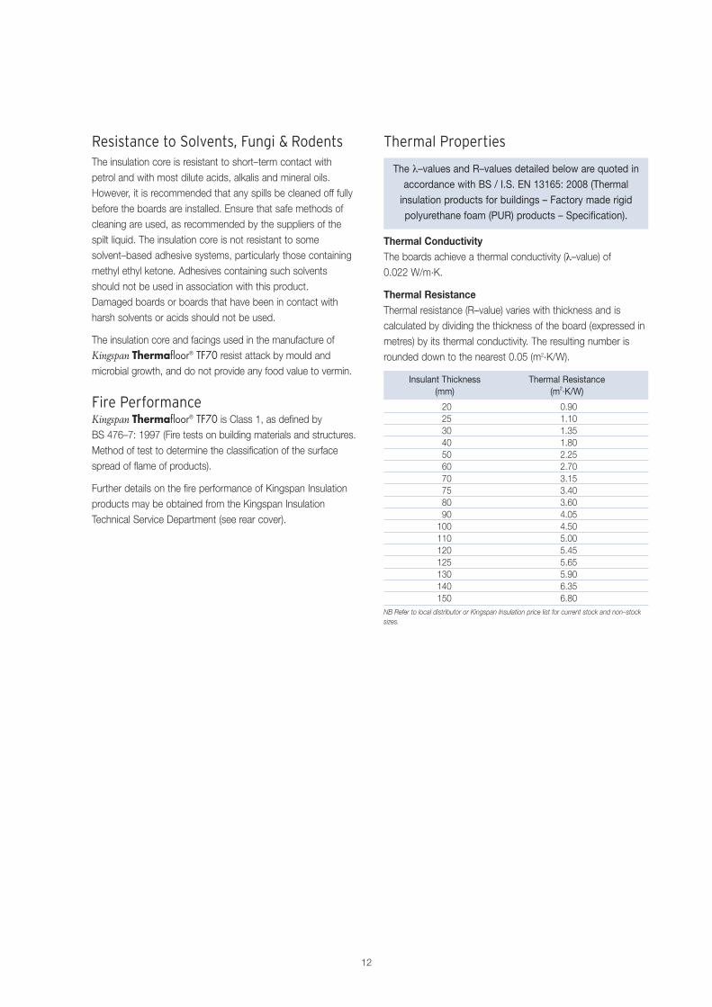
Thermal Properties
The λ–values and R–values detailed below are quoted inaccordance with BS / I.S. EN 13165: 2008 (Thermalinsulation products for buildings – Factory made rigidpolyurethane foam (PUR) products – Specification).
Thermal ConductivityThe boards achieve a thermal conductivity (λ–value) of 0.022 W/m.K.
Thermal ResistanceThermal resistance (R–value) varies with thickness and iscalculated by dividing the thickness of the board (expressed inmetres) by its thermal conductivity. The resulting number isrounded down to the nearest 0.05 (m2.K/W).
Insulant Thickness Thermal Resistance(mm) (m2.K/W)
20 0.9025 1.1030 1.3540 1.8050 2.2560 2.7070 3.1575 3.4080 3.6090 4.05100 4.50110 5.00120 5.45125 5.65130 5.90140 6.35150 6.80
NB Refer to local distributor or Kingspan Insulation price list for current stock and non–stocksizes.
Resistance to Solvents, Fungi & RodentsThe insulation core is resistant to short–term contact withpetrol and with most dilute acids, alkalis and mineral oils.However, it is recommended that any spills be cleaned off fullybefore the boards are installed. Ensure that safe methods ofcleaning are used, as recommended by the suppliers of thespilt liquid. The insulation core is not resistant to somesolvent–based adhesive systems, particularly those containingmethyl ethyl ketone. Adhesives containing such solventsshould not be used in association with this product. Damaged boards or boards that have been in contact withharsh solvents or acids should not be used.
The insulation core and facings used in the manufacture ofKingspan Thermafloor® TF70 resist attack by mould andmicrobial growth, and do not provide any food value to vermin.
Fire PerformanceKingspan Thermafloor® TF70 is Class 1, as defined byBS 476–7: 1997 (Fire tests on building materials and structures.Method of test to determine the classification of the surfacespread of flame of products).
Further details on the fire performance of Kingspan Insulationproducts may be obtained from the Kingspan InsulationTechnical Service Department (see rear cover).

1313
Kingspan Insulation
Company DetailsKingspan Insulation Ltd is part of the Kingspan Group plc., one of Europe’s leading construction product manufacturers.The Kingspan Group was formed in the late 1960s and is apublicly quoted group of companies headquartered inKingscourt, County Cavan, Ireland.
Kingspan Insulation Ltd is a market leading manufacturer of premium and high performance rigid insulation products and insulated systems for building fabric and building services applications.
Products & ApplicationsKingspan Insulation Ltd has a vast product range. Kingspan Insulation Ltd products are suitable for both new build and refurbishment in a variety of applications withinboth domestic and non–domestic buildings.
Insulation for:● Pitched Roofs
● Flat Roofs
● Green Roofs
● Cavity Walls
● Solid Walls
● Timber and Steel Framing
● Insulated Cladding Systems
● Insulated Render Systems
● Floors
● Soffits
● Ductwork
Further Solutions:● Insulated Dry–Lining
● Tapered Roofing Systems
● Cavity Closers
● Kingspan KoolDuct® Pre–Insulated Ducting
● Kingspan nilvent ® Breathable Membranes
● Kingspan TEK® Building System
Insulation Product BenefitsKingspan Kooltherm® K–range Products● With a thermal conductivity of 0.020–0.023 W/m.K these
are the most thermally efficient insulation productscommonly used.
● The thinnest commonly used insulation products for anyspecific U–value.
● Rigid thermoset insulation core is Class 0, as defined by the Building Regulations in England, Wales & Ireland, and Low Risk, as defined by the Building Standards in Scotland.
● Rigid thermoset insulation core achieves the best possiblerating of < 5% smoke obscuration when tested to BS5111: Part 1: 1974.
● Manufactured with a blowing agent that has zero OzoneDepletion Potential (ODP) and low Global WarmingPotential (GWP).
Kingspan Therma™ Range Products● With a thermal conductivity of 0.022–0.027 W/m.K these
are amongst the more thermally efficient insulationproducts commonly used.
● Each product achieves the required fire performance for itsintended application.
● Manufactured with a blowing agent that has zero OzoneDepletion Potential (ODP) and low Global WarmingPotential (GWP).
Kingspan Styrozone® Range Products● Rigid extruded polystyrene insulation (XPS) has the
necessary compressive strength to make it the product ofchoice for specialist applications such as heavy dutyflooring, car park decks and inverted roofing.
● Each product achieves the required fire performance for itsintended application.
● Manufactured with a blowing agent that has zero OzoneDepletion Potential (ODP).
All Products● Their closed cell structure resists both moisture and water
vapour ingress – a problem which can be associated withopen cell materials such as mineral fibre and which canresult in reduced thermal performance.
● Unaffected by air infiltration – a problem that can beexperienced with mineral fibre and which can reducethermal performance.
● Safe and easy to install – non–fibrous.
● If installed correctly, can provide reliable long term thermalperformance over the lifetime of the building.

14
Notes

15
Contact Details
Customer ServiceFor quotations, order placement, details of despatches and general enquiries.
Tel: +353 (0) 42 979 5000 Fax: +353 (0) 42 975 4299 email: [email protected]
Technical Advice / DesignKingspan Insulation supports all of its products with a comprehensive Technical Advisory Service for specifiers, stockists and contractors.
Tel: +353 (0) 42 975 4297 Fax: +353 (0) 42 975 4296 email: [email protected]
Kingspan Insulation LtdCastleblayney, County Monaghan, Ireland
Pembridge, Leominster, Herefordshire HR6 9LA, UK
www.kingspaninsulation.co.uk www.kingspaninsulation.ie
® Kingspan, KoolDuct, Kooltherm, nilvent, Styrozone, TEK, the oz Device and the Lion Device are Registered Trademarks of the Kingspan Group plc in the UK, Ireland and other countries. All rights reserved.
Registered in England & Wales, No. 01882722. Registered Office: Pembridge, Leominster, Herefordshire HR6 9LA, UK. VAT GB428602456.Registered in Ireland, No. 152775. Registered Office: Bree Industrial Estate, Castleblayney, Co. Monaghan, Ireland. VAT IE6550175J.