solid dielectric switch with visible break · solid dielectric switch with visible break ... -...
TRANSCRIPT

Solid Dielectric Switch with Visible Break
• Operator safety
• Load break or fault interrupting
applications
• Clear visible break of all three phases
• Solid dielectric insulation
• Compact, lightweight construction
• Fully submersible
• Ideal replacements for oil fuse cutouts
• Integral self-powered overcurrent
protection available
• Resettable spring operated mechanism
Catalog S-tsv13

G & W E L E C T R I C P A G E 2
Trident solid dielectric two way switches now include an innovative visible break feature built into the switch, which eliminates the need to remove elbows or use externally mounted linkage systems to provide a visible open. This makes the Trident with SafeVu™ ideal for subsurface applications where space and safety practices prevent the linemen from entering the vault to perform these functions.
Oil Fuse Cutout Replacement – Eliminate the need to replace fuse links or maintain insulating oil. The Trident with SafeVu does not require any maintenance and features compact size, lightweight, integral visible break, and fault interrupting capability. It is the perfect solution to replace obsolete oil fuse cutouts.
OperatiOnThe visible break is achieved with a blade type switch incorporated within the solid dielectric module. The blade is in series with the vacuum interrupter and provides a clear visible open. The blade is easily visible through a viewing window molded as an integral part of each module. If the application calls for a resettable fault interrupter, the Trident with SafeVu can be supplied with integral current transformers (CTs) and a self-powered G&W vacuum interrupter overcurrent protection control. The CTs and CT leads are molded within the solid dielectric module, protecting them from the environmental conditions of subsurface vaults. The CTs are dual ratio and preset for either 500:1 or 1000:1. The G&W Type 7 control is particularly well suited for subsurface applications, as it is housed within the Trident mechanism housing.
FeaturesOperator Safety – All load and fault currents are safely interrupted inside vacuum interrupters molded within solid epoxy insulation. The entire module is coated with a semi-conductive layer of epoxy, providing a completely deadfront device, enhancing operator safety. The switch features two mechanical interlocks, external and internal, for safe operation. The external mechanical interlock ensures the switch is operated in the correct sequence. The internal mechanical interlock requires the vacuum interrupter to break all load and fault currents prior to the operation of the visible break switch.
Submersibility – Trident with SafeVu has been tested to IP68 standards to withstand a 20 foot head of water pressure for 20 days. The switch will remain fully operable after withstanding prolonged submersion at depths of up to 20 feet (6m).
Compact, Lightweight Construction - The Trident with SafeVu features a small footprint and is designed to fit through a 27” manhole opening. The small footprint allows installation inside existing subsurface vaults. The switch is much lighter than comparable oil insulated devices, making it easier and safer to install, especially in the tight
confines of a subsurface vault. The switch can be mounted in any orientation to ease cable training and operation.
p Viewing windows are molded into the epoxy modules, providing a clear view of the visible break.
ratingsThe switch is designed, tested and built per IEEE C37.74 for load break switching, IEEE C37.60 for fault interrupting, IEEE 386 for bushing specification, and IEC 60529 for environmental protection rating. Certified test reports are available.
Max System Voltage (kV) 17.1BIL (kV) 95
Continuous Current (A) 630
Peak, asym (kA) 32
Momentary Current, RMS, asym (kA) 20
Making Current, RMS, asym (kA) 20
Interrupting Rating, RMS, sym (kA) 12.5Short Circuit Current, kA sym, 1
second 12.5
AC Withstand, RMS, Dry, 1 minute (kV) 35
DC Withstand, 15 minutes (kV) 53
Mechanical Operations 2,000
Fault Interrupting Duty per IEEE C37.60
44 operations at 15-20% rated
interrupting current56 operations
at 45-55% rated interrupting current
16 operations at 90-100% rated
interrupting current
Submersibility Rating per IP6820 days under a 20 foot head of
water
Trident with SafeVu

G & W E L E C T R I C P A G E 3
Mechanismhousing
200A Bushing wells
200A Bushing wells
Viewing window
Parking stand
Ground boss for system grounding
Ground boss for cable and elbow grounding
Mounting bracket
Solid dielectric module
Motor OperatorOptional
Interrupter open/closed indication
trident with saFeVu COmpOnents

G & W E L E C T R I C P A G E 4
Dimensions are approximate.Approximate weight: 200 lb.
33.8”(861mm)
25.9”(658mm)
5.4”(137mm)
Viewing window
600A Deadbreak ApparatusBushings
Visible Break Switch in Closed Position Visible Break Switch in Open Position
Visible break switch
Vacuum bottle
23.7”(603mm)
8.6”(219mm)
7.5”(191mm)
42.6”(1081mm)
Max handle level
Front View Side View
dimensiOns
Visible break OperatiOn
Visible break switch handle
Interrupter handle
Interrupter open/closed indication
Parkingstand
Lifting provision
Mechanismhousing
Solid dielectric module
Trident with SafeVu
G & W E L E C T R I C P A G E 5
This
draw
ing an
d the
infor
matio
n the
reon a
re an
d rem
ain th
e pr
oper
ty of
G&W
and a
re no
t to b
e cop
ied, re
prod
uce
d or d
iclos
ed to
othe
rs wi
thou
t the
ex
pres
sed w
ritten
cons
ent o
f G&W
.
G&W ELECTRIC Co.
* ALL PRIMARY DIMENSIONS ARE IN INCHES. ALL SECONDARY DIMENSIONS ARE IN MILLIMETERS.
D97
00 7
FCR
E00
DWG.
NO.
:3D
MOD
EL M
C ER
RORS
1DR
AWIN
G M
C ER
RORS
23D
MOD
EL LA
ST C
HECK
ED Tu
e Jul
16 20
13 13
:26:20
GM
T-06
00 S
TAND
ARD
DRAW
ING
LAST
CHE
CKED
Fri
Aug
09 20
13 16
:40:46
GM
T-06
00 ST
ANDA
RDSH
EET 1
of 3
1 of 3SHEET: SCALE: DATE: APPR BY:
REV
DRAWING NO.
D9700 7FCR E00Aug-09-13DATE:KADDRAWN BY:
TRIDENT WITH SAFEVU MOTORIZEDCAT. NO.:
MOTORIZED TRIDENT-S WITH SAFEVU SWITCH200 AMP DEEPWEEL INTERFACE
TRIDENT WITH SAFEVU MOTORIZED
ALL DRAWING CHANGES MUST BE MADE ON CAD. ANY MANUAL CHANGES WILL VOID DRAWING.
REVISIONS
DATECHANGEREV.
DRAWING REVIEW TEAM
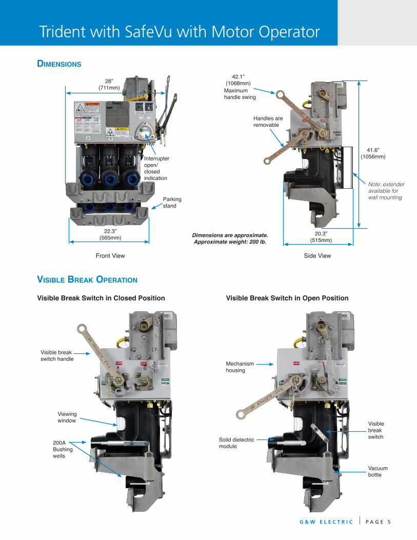
Dimensions are approximate.Approximate weight: 200 lb.
41.6”(1056mm)
42.1”(1068mm)28”
(711mm)
Viewing window
200A Bushing wells
Visible Break Switch in Closed Position Visible Break Switch in Open Position
Visible break switch
Vacuum bottle
Trident with SafeVu with Motor Operator
Front View Side View
dimensiOns
Visible break OperatiOn
Visible break switch handle
Interrupter open/closed indication
Parkingstand
Mechanismhousing
Solid dielectric module
22.3”(565mm)
20.3”(515mm)
Handles are removable
Maximum handle swing
Note: extender available for wall mounting

G & W E L E C T R I C P A G E 6
p Type 3 control
g&w VaCuum interrupter COntrOlsThe control monitors the current, sends a trip signal which opens the vacuum interrupters and interrupts the fault current. G&W controls are self-powered from the current transformers located inside the solid dielectric module. Controls can be equipped to accept a trip input from a relay or communication device. G&W also offers other controls, such as SEL relays, depending on the application.
The standard control enclosure for padmount applications is fiberglass NEMA 4X (IP56) rated. For vault and subsur-face applications, G&W recommends the Type 7 control. The Type 7 is mounted within the switch’s mechanism housing and has an IP68 rating for long term submersion.
g&w COntrOl OptiOnsType 2 controls provide a user friendly interface for quick and easy programming. Trip level selections can be made under load or no-load conditions with current ranges in 12 selectable levels. Two ranges of minimum trip settings are available, 15 to 300 amps and 30 to 600 amps. Each unit is pre-programmed with 30 Time Current Characteristic (TCC) curves. The curve selection can be set or changed at any time.
An 8 pole dip switch allows the user to choose the TCC curve which best matches their specific coordination requirements. The control can be factory preset to meet the user’s requirements. As protection or coordination requirements change, settings can easily be changed in the field. Pressing the manual trip button when the control is powered up trips all three phases of the vacuum interrupter. Each control also includes “Last Cause of Trip” LEDs. These LEDs indicate what caused the control to issue a trip command - an over current condition, Ground Fault, Instantaneous, or an external or manual trip command.
Type 2 controls offer the following features: - Three phase protection
- Minimum trip setting for all three phases with one selector switch - Adjustable phase time delay - Ground fault (phase imbalance) for protection of large three phase motors or transformers. The ground trip setting is represented as a percent of the minimum trip setting. - Instantaneous trip and inrush restraint features
Type 3 and 4 controls provide advanced protection functions. There are two versions of these controls, each with different protection elements.
The EZset version includes: - Phase Minimum Trip - Phase Time Delay - Phase Instantaneous - Phase Minimum Response - Phase Inrush (Cold Load Pickup) Restraint - Ground Fault (Phase Imbalance) Minimum Trip with a
Separate Curve - 30 Phase/Ground Fault Curve selectors
The Plus version includes all of the above, and in addition includes: - Ground Fault Time Delay - Ground Fault Instantaneous - Ground Fault Minimum Response - Ground Fault Inrush (Cold Load Pickup) Restraint - 60 Phase/ Ground Fault Curves including 5 User
Creatable Curves - Maintenance Setting Group
The Type 3 and 4 controls record the 16 most recent Cause of Trip Events. The Type 3 EZset includes a display and keypad for entering programming parameters and viewing the Cause of Trip Events. The Type 3 Plus, and Type 4 EZset and Plus utilize a laptop programming kit to enter the settings. The laptop programming kit can also be used to download and store the settings and Cause of Trip Events.
p Type 2 control
Options

G & W E L E C T R I C P A G E 7
p Type 7 control programming port
prOgramming kitFor Type 3, Type 4, or Type 7 Provides software and cable connection to a laptop com-puter for programming or retrieving vacuum interrupter control information. The cable connects the USB port of the computer to the Vacuum Interrupter Control (Type 3 or 4) or mechanism housing (Type 7).
Catalog Number for Type 3, Type 4, Type 7: LPK7-VICSS
Other COmpatible relays FOr OVerCurrent prOteCtiOnVarious other relays can be provided with Trident switch-gear including Schweitzer’s model SEL-501, SEL-551, SEL-351S and SEL-751A.
JunCtiOn bOxFor auxiliary contacts and remote power/remote trip connec-tions. Includes NEMA 4X (IP56) enclosure with terminal strip connections. grOund lugsBronze, eyebolt style ground lugs are avail-able for 4/0 maximum conductor cable.
FramesBolted, galvanized mounting frames are available for verti-cal mounting of vault style switches providing a 24” distance from the ground to the center of the bottom bushing. Other size frames are available. Consult your G&W representative for avail-ability.
bushings Bushings shall be tested to IEEE 386. The switch is avail-able with either 600A deadbreak apparatus bushings or 200A bushing wells. 600A deadbreak apparatus bushings are suitable for use with T-body elbows. 200A bushing wells can be used with 200A load break inserts and elbows.
auxiliary COntaCtsAuxiliary contacts are mounted within the mechanism housing to provide remote indication of the vacuum interrupter contact position. One normally open and one normally closed Form C contact is provided.
mOtOr OperatOrMotor operators can easily be mounted on the operating mechanism of switches already installed in the field. Motor operators permit remote operation using a variety of G&W controls. The operating time for a single open or close operation is 2 to 3 seconds. Motor operators are completely s u b m e r s i b l e and made from cast 304 stain-less steel which is permanently bonded and sealed for maxi-mum corrosion resistance.
p Programming Kit
Type 7 controls provide the same protection features and options as the Type 3 and 4 controls, except that the con-trols are mounted within the switch mechanism housing. This eliminates the need for a separate control enclosure and associated cabling. The control is programmed using a laptop computer. A laptop programming kit is available.
p Ground lug

G & W E L E C T R I C P A G E 8
hOw tO Order - trident®
with saFeVu switChgear FOr lOad break appliCatiOns
Fill in the spaces using the tables below to build your G&W catalog number:
Configuration
Voltage Class
Number of Phases
Description Code
Bushings front; side mounted handle A
Description Code
Trident-S, three phase, with SafeVu V
Description Code
Load break switch L
ATS control; ATC451 A
Pre-engineered control; Relay, IED, RTU E
Customer supplied control W
Switch Style
Options
kV Code
15 1
Mounting
Controls
Description Code
No options 0Auxiliary contacts
(vacuum load break switch only) 1
Motor actuator 2
Custom engineered 9
Description Code
Padmount, front access, vertical mount P
Padmount, front access, horizontal mount H
Vault, submersible switch, non-submersible electronics (if specified) V
Vault, submersible switch, submersible electronics (if specified) W
1
2
3
4
5
6
7
Phase Code
Three 3
_ A 1 3 - V _ _ 21 3 4 5 6 7 8
Description Code
200A Bushing Wells 2
600A Deadbreak Apparatus Bushings 6
Bushing Arrangement8
Applicable One-lineVisible Break switch
Vacuum Load Break switch
Ordering Information
For Multi-way Trident with SafeVu ordering information see Trident catalog (S-trid13)

G & W E L E C T R I C P A G E 9
hOw tO Order - trident®
with saFeVu switChgear FOr Fault interrupting appliCatiOns
Fill in the spaces using the tables below to build your G&W catalog number:
Configuration
Voltage Class
Number of Phases
Description Code
Bushings front; side mounted handle A
Description Code
Trident-S, three phase, with SafeVu V
Description Code
Type 1 1
Type 2 2
Type 3 3
Type 4 4
Type 7 7
Pre-engineered control; Relay, IED, RTU E
Provisions for future use (includes junction box with CT and trip connections) P
Customer supplied control W
Switch Style
Options
kV Code
15 1
Mounting Controls
Description Code
No options 0
Auxiliary contacts (vacuum fault interrupter only) 1
Motor actuator 2
Custom engineered 9
Type 3, 4, or 7 Plus Control P
Description Code
Padmount, front access, vertical mount P
Padmount, front access, horizontal mount H
Vault, submersible switch, non-submersible electronics (if specified) V
Vault, submersible switch, submersible electronics (if specified) W
6
Phase Code
Three 3
_ A 1 3 - V _ _ 21 3 4 5 6 7 8
Description Code
200A Bushing Wells 2
600A Deadbreak Apparatus Bushings 6
Bushing Arrangement8
)
Applicable One-lineVisible Break switch
Vacuum Fault Interrupter
1
2
3
4
5
7
For Multi-way Trident with SafeVu ordering information see Trident catalog (S-trid13)

G & W E L E C T R I C P A G E 1 0
Multi-way Trident with SafeVu
p View of the back of the switch shows the flexible inter-way bus connection system.

G & W E L E C T R I C P A G E 1 1For Multi-way Trident with SafeVu ordering information see Trident catalog (S-trid13)
60.1”(1528mm)
Max handle level
51.4”(1307mm)
34”(864mm)
87”(2210mm)

G&W offers a complete line of smart distribution voltage equipment including:
SF6 Insulated Switchgear• To 38kV, 25kA interrupting
• Submersible vault and padmount
• Smart Grid / Lazer® solutions
• Load and fault interrupting
Solid Dielectric Switchgear• To 38kV, 16kA interrupting
• Submersible vault and padmount
• Smart Grid / Lazer® solutions
• Single phase and three phase
• Integral Visible Break Designs
Solid Dielectric Reclosers• To 38kV, 12.5kA interrupting
• To 27kV, 16kA interrupting
• Overhead, substation and padmount
• Smart Grid / Lazer® solutions
• Single phase and three phase
• Six voltage sensing available
Lazer® Automation
• Multiple levels of protection
• Open, flexible communication
• Pre-engineered, factory tested
• Transfer, loop, and network applications
G&W Electric Company305 W. Crossroads PkwyBolingbrook, IL 60440-4938 USATel 708.388.5010 Fax 708.388.0755
www.gwelec.comISO 9001:2008 CertifiedISO 14001:2004 Certified
Catalog S-tsv13December, 2013