solid fuel warm air furnace - united states stove …usstove.com/resources/ownersmanuals/english...
TRANSCRIPT

1•DRAWINGS FOR ILLUSTRATION PURPOSES ONLY•
Model 1200QSOLID FUEL WARM AIR FURNACE
Owners Manual
COMPANY
UNITED STATES STOVE
CSSUWARNOCK HERSEY
R
*FOR PARALLEL INSTALLATION WITH ANEXISTING FORCED AIR, GAS OR OIL
FIRED FURNACE (U.S. ONLY)*FOR INSTALLATION AS A CENTRAL FURNACE
DO NOT USE THIS FURNACE IN A MOBILE HOME OR TRAILER
Improper Installation MayVoid Your Warranty
Save This Manual ForFuture Reference
CAUTION:Read All Instructions Carefully BeforeStarting the Installation or Operating theFurnace.
851282A 4/99
HTBL STAO
UNITED STATES STOVE COMPANY227 Industrial Park Road
P.O.Box 151South Pittsburg, TN 37380
(423) 837-2100
2 •DRAWINGS FOR ILLUSTRATION PURPOSES ONLY•
TOOLS AND MATERIALS NEEDED
TOOLSPencil6 Foot Folding Rule or TapeTin SnipsDrill, Hand or ElectricDrill Bit (For Sheet Metal Screws) 1/8" Dia.Screw Driver (Blade-Type)GlovesSabre Saw5/16" Nut Driver or5/16" Socket with Rachet
MATERIALS6" Pipe, 6" Elbow, Collar and Thimble; as required (24 gauge min.)1/2" Sheet Metal Screws6" Inside Diameter Listed Residential Type or Building Heating Appliance Chimney or Existing Masonry Chimney (SEE Page 8).Electrical Wiring6" Draft Regulator1/2" Conduit(Conduit Connectors)Furnace Cement (Manufacturer Recommends: Rutland Black - Code 78 or EquivalentPlenum and Duct Work as Required
CONGRATULATIONS!
You've purchased one of America's Finest Wood Burning Furnaces.By heating with wood you're helping to CONSERVE AMERICA'S ENERGY!Wood is our Renewable Energy Resource. Please do your part to preserve ourwood supply. Plant at least one tree each year. Future generations will thank you.
NOTE: YOUR UNIT MUST BE INSTALLED BY A QUALIFIED FURNACEINSTALLER. IMPROPER INSTALLATION COULD VOID YOURWARRANTY! NOTE: (See Page 5, First Paragraph)

3•DRAWINGS FOR ILLUSTRATION PURPOSES ONLY•
CAUTION:Your Furnace has the following labels. Read and obey all labels.
REFER TO MARKINGS ON THE APPLIANCE FOR ADDITIONAL INFORMATION.
CAUTION!INSPECT FLUE PIPES, FLUE PIPE JOINTS AND FLUE PIPE SEALSREGULARLY TO ENSURE THAT SMOKE AND FLUE GASES ARE NOTDRAWN INTO, AND CIRCULATED BY, THE AIR CIRCULATION SYSTEM.
CAUTION!CLEANOUT OF THE HEAT EXCHANGER, FLUE PIPE, CHIMNEY, ANDDRAFT INDUCER IF USED, IS ESPECIALLY IMPORTANT AT THE ENDOF THE HEATING SEASON TO MINIMIZE CORROSION DURING THESUMMER MONTHS, CAUSED BY ACCUMULATED ASH.
If this heater is not properly installed, a housefire may result. For your safety, follow the in-stallation directions. Contact local building or fireofficials about restrictions and installation in-spection requirements in your area.
SAFETYNOTICE:
DANGER: RISK OF FIRE OR EXPLOSION.
DO NOT burn garbage, gasoline, drain oil, or other flammable liquids.
WARNING: FIRE HAZARD.
DO NOT operate with fire draft exceeding .06 inches W.C.
DO NOT operate with fuel loading or ash removal doors open.
DO NOT store fuel or other combustible material within the marked installation clearances.
DO NOT store fuels, paints, thinners, flammable liquids, or other highly volatile substancesin the furnace room.
CAUTION: HOT SURFACES Keep children away. Do not touch during operation.
WARM-AIR SUPPLY-DUCT SYSTEM MUST BE CONSTRUCTED ONLY OF METAL

4 •DRAWINGS FOR ILLUSTRATION PURPOSES ONLY•
Read these rules and the instructions carefully. Failure to follow them will cause a hazard that could result indeath, serious bodily injury, and/or property damage.
Check your local codes. This installation must comply with their rulings.
Do not install this furnace in a mobile home or trailer.
Always connect this furnace to a chimney and vent to the outside. Never vent to another room orinside a building.
Do not connect this furnace to an aluminum Type B gas vent. This is not safe and is prohibited by theNational Fire Protection Association Code. This furnace requires a masonry or listed factory builtchimney for residential type or building heating appliance chimney. Use a 6" diameter chimney orlarger, that is high enough to give a good draft. (See Page 8)
Be sure that if a masonry chimney is used, it is safely constructed and in good repair. Have thechimney inspected by the Fire Department or an inspector.
Inspect chimney connector and chimney before and frequently during the heating season for anydeposit of creosote or soot which must be removed (see Chimney Maintenance, page 21.)
Provide air for combustion into the room where the furnace is located. If the intake is not in the sameroom, air must have free access to the room.
CAST IRON PARTS MUST BE "SEASONED" TO AVOID CRACKING. BUILD ONLY SMALL FIRESON FIRST USE.
To prevent injury, do not allow anyone to use this furnace who is unfamiliar with the correct operationof the furnace.
For further information on using your furnace safely, obtain a copy of the National Fire ProtectionAssociation (NFPA) publication "Chimney's, Fireplaces and Solid Fuel Burning Appliances" NFPA211. The address of the NFPA is Batterymarch Park, Quincy, MA 02269.
Keep the ashpit section free of excess ashes. Do not allow ashes to stack higher than the sides of theash pan.
DISPOSAL OF ASHES - Place ashes in a metal container with a tight fitting lid. Keep the closedcontainer on a noncombustible floor or on the ground, well away from all combustible materials. Keepthe ashes in the closed container until all cinders have thoroughly cooled. The ashes may be buriedin the ground or picked up be a refuse collector.
CAUTION - The special paints used on your furnace may give off some smoke while they are curingduring first few fires. Build small fires at first. The metal used in construction of the furnace and ductwork has a light coating of oil. This could give off smoke and/or odors from registers when furnace isused for the first time. This should disappear after a short period of time. Once this burn-off hasoccurred, it should not reoccur.
1.
2.
3.
4.
5.
6.
7.
8.
9.
10.
11.
12.
13.
RULES FOR SAFE INSTALLATION AND OPERATION

5•DRAWINGS FOR ILLUSTRATION PURPOSES ONLY•
Your Supplemental Furnace is designed to bea supplemental or central heating source for yourhome. This solid fuel furnace may be installed inconjunction with a properly operating central fur-nace that is listed or certified in accordance withnationally recognized safety standards andequipped with the required controls and othersafety features and which has been installed withappropriate standards of National Fire ProtectionAssociation with installation clearances specifiedin the furnace nameplate marking. The installationmust be accomplished by a qualified agency (onewho is engaged in, and is responsible for, or isthoroughly familiar with the installation and opera-tion of the gas, oil, and solid fuel burning heatingappliances, who is experienced in such work,familiar with all precautions required, and hascomplied with all the requirements of the authorityhaving jurisdiction.) The installation shall be instrict accordance with the manufacturer's installa-tion instructions furnished with the solid fuel fur-nace.
The chimney connector of the furnace is to beinstalled to provide clearances to combustiblematerial not less than specified in the individualclassifications and marked on the furnace. Thechimney connector must be connected to a chim-ney suitable for use with residential type or buildingheating appliances which burn solid fuel.
The furnace is designed to operate in eitherparallel or series air flow arrangement with thecentral furnace or as a central furnace.
HOW THE FURNACE FUNCTIONS
Your Furnace is designed to be installed in a parallel air flow arrangement with a gas or oil-firedforced air upflow-type central furnace, or it may be installed as a central furnace.
CARING FOR PAINTED PARTS - This furnace has a painted outside jacket, which is durable but itwill not stand rough handling or abuse. When installing you furnace, use care in handling. Clean withsoap and warm water when furnace is not hot. DO NOT use any acids or scouring soap, as thesewear and dull the finish. DISCOLORATION WILL OCCUR IF THE FURNACE IS OVERFIRED.FOLLOW OPERATING INSTRUCTIONS CAREFULLY.
Keep the feed and ash doors closed at all times except while tending the furnace.
14.
15.
RULES FOR SAFE INSTALLATION AND OPERATION
PARALLEL INSTALLATION: The design is suchthat when the blower comes on, the blower on thecentral system also comes on.
The blower will only come on when thetemperature in the plenum has reached the set-ting on the blower control. This is to insure thatthere is sufficient warm air in the system to makeit efficient for the unit to operate. When the centralsystem thermostat calls for heat, the central sys-tem will operate by the burner igniting and theblower coming on. It is possible that both systemswill operate simultaneously. It is recommendedthat for the most efficient use of yourSupplemental Furnace, that it be fired as much aspossible in order to reduce the demand on yourexisting central heating system.
The warm air supply outlet of thesupplementary furnace shall not be connected tothe cold air return inlet of the central furnacebecause the possibility exists of components ofthe central furnace overheating and causing thecentral furnace to operate other than is intended.
CENTRAL FURNACE INSTALLATION: As a cen-tral furnace, the unit functions independently ofany other system. The blower will come on whenthe plenum temperature reaches the setting onthe blower control.

6 •DRAWINGS FOR ILLUSTRATION PURPOSES ONLY•
MODEL 1200Q DIMENSIONS
FIG. 1
7•DRAWINGS FOR ILLUSTRATION PURPOSES ONLY•
1.
2.
3.
4.
FIG. 3
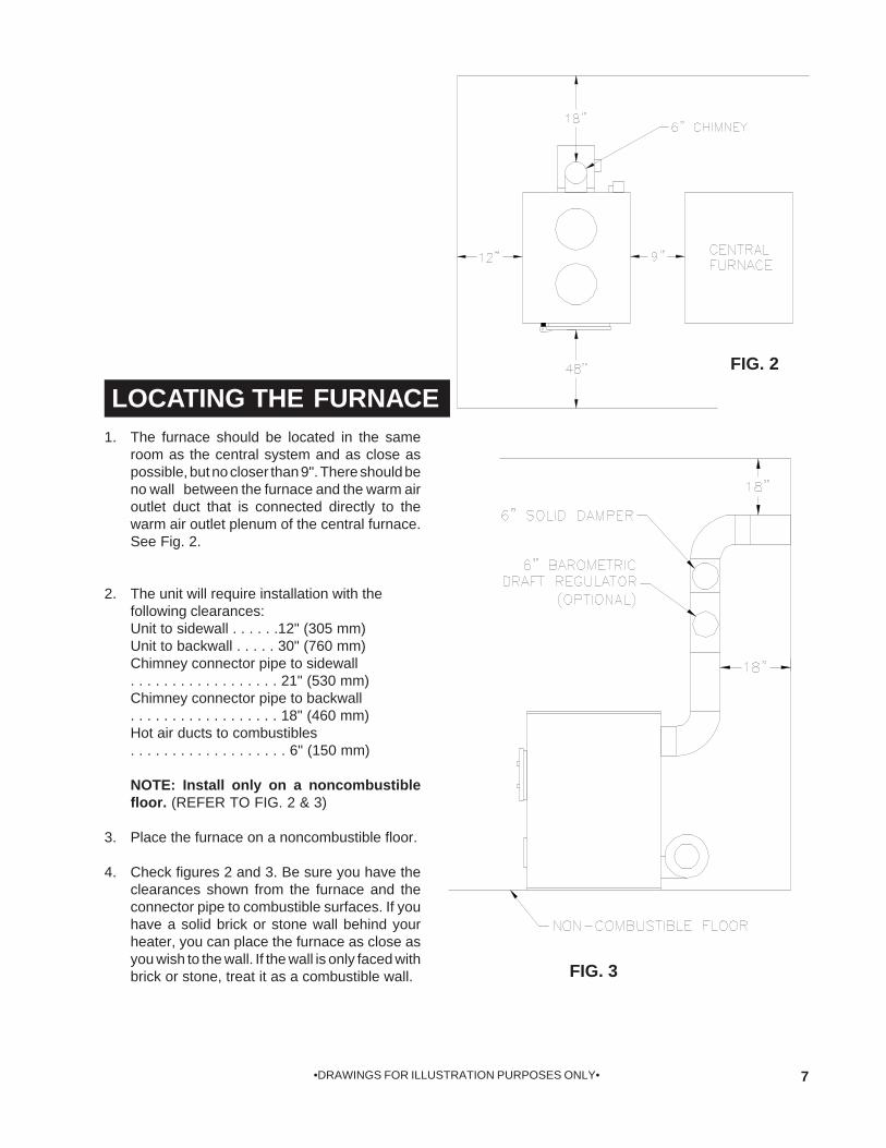
The furnace should be located in the sameroom as the central system and as close aspossible, but no closer than 9". There should beno wall between the furnace and the warm airoutlet duct that is connected directly to thewarm air outlet plenum of the central furnace.See Fig. 2.
The unit will require installation with thefollowing clearances:Unit to sidewall . . . . . .12" (305 mm)Unit to backwall . . . . . 30" (760 mm)Chimney connector pipe to sidewall. . . . . . . . . . . . . . . . . . 21" (530 mm)Chimney connector pipe to backwall. . . . . . . . . . . . . . . . . . 18" (460 mm)Hot air ducts to combustibles. . . . . . . . . . . . . . . . . . . 6" (150 mm)
NOTE: Install only on a noncombustiblefloor. (REFER TO FIG. 2 & 3)
Place the furnace on a noncombustible floor.
Check figures 2 and 3. Be sure you have theclearances shown from the furnace and theconnector pipe to combustible surfaces. If youhave a solid brick or stone wall behind yourheater, you can place the furnace as close asyou wish to the wall. If the wall is only faced withbrick or stone, treat it as a combustible wall.
LOCATING THE FURNACE FIG. 2

8 •DRAWINGS FOR ILLUSTRATION PURPOSES ONLY•
LISTED FACTORY BUILT CHIMNEYCarefully follow chimney manufacturer's instructions. Use only a Listed Residential Type or Building HeatingAppliance Chimney. If your chimney starts at the ceiling (Fig. 5), you will need enough 6" pipe to reach the ceiling.The top of the chimney must be at least 3 feet above the roof and be at least 2 feet higher than any point of theroof within 10 feet (Fig. 5).
FIG. 5
MASONRY CHIMNEYBefore using an existing masonry chimney, clean the chimney and inspect the flue liner to be sure it is safe to use.Make repairs before attaching the furnace. See Page 4, item 5. Look at Fig. 4. The connector pipe and fittingsyou will need to connect directly to a masonry chimney are shown.The chimney connection should be as short as possible. If the connector pipe must go through a combustible wallbefore entering the masonry chimney, consult a qualified mason or chimney dealer. The installation must conformto local fire codes, and N.F.P.A. 211.
DO NOT CONNECT THIS FURNACE TO A CHIMNEY FLUE SERVING ANOTHER APPLIANCE.The chimney used for a furnace must not be used to ventilate the cellar or basement. If there is a cleanout openingat the base of the chimney, close it tightly.
FIG. 4
CHIMNEY CONNECTION

9•DRAWINGS FOR ILLUSTRATION PURPOSES ONLY•
RULES FOR CONNECTOR PIPE INSTALLATION
FIG. 6
The crimped end of the chimney connectorfits inside the furnace flue collar. Installadditional chimney connector and elbowwith the CRIMPED END TOWARD THEFURNACE. This will allow any con-densation in the flue to run back into thefurnace. Use 6" dia. (minimum 24 gauge)black chimney connector.Slope any horizontal pipe upward toward thechimney at least 1/4 inch for each foot ofhorizontal run.You must have at least 18 inches ofclearance between any horizontal pipingand the ceiling. (See Fig. 3)The chimney connector must not extendinto the chimney flue (See Fig. 6).Seal each chimney connector pipe joint withfurnace cement. Also seal the pipe at thechimney.Use 3 sheet metal screws at each chimneypipe joint to make the piping rigid.The chimney connector may include a sec-tion for a barometric draft regulator betweenthe furnace and the chimney (Fig. 4, 5, 6, &7). The barometric draft regulator must beinstalled in the same room (same pressurezone) as the furnace.Install the barometric draft regulator strictlyin accordance with the instructions that areprovided with the barometric draft regu-lator.A solid damper can be placed between thebarometric draft regulator and the chim-ney. (Fig. 4, 5, 6, & 7)
1.
2.
3.
4.
5.
6.
7.
8.
9.
FIG. 7
Adjusting theBarometric Draft Regulator
Drill a hole in the chimney connector within18" of the flue collar below the barometricdraft regulator just large enough for thetube of the manometer.Build a fire after all chimney connectionshave been made.Use a manometer to measure the draft inthe flue. (U.S. Stove Model DG-26)Adjust the barometric draft regulator toobtain a draft of 0.05" - 0.06" W.C. understable conditions.
1.
2.
3.
4.
10 •DRAWINGS FOR ILLUSTRATION PURPOSES ONLY•
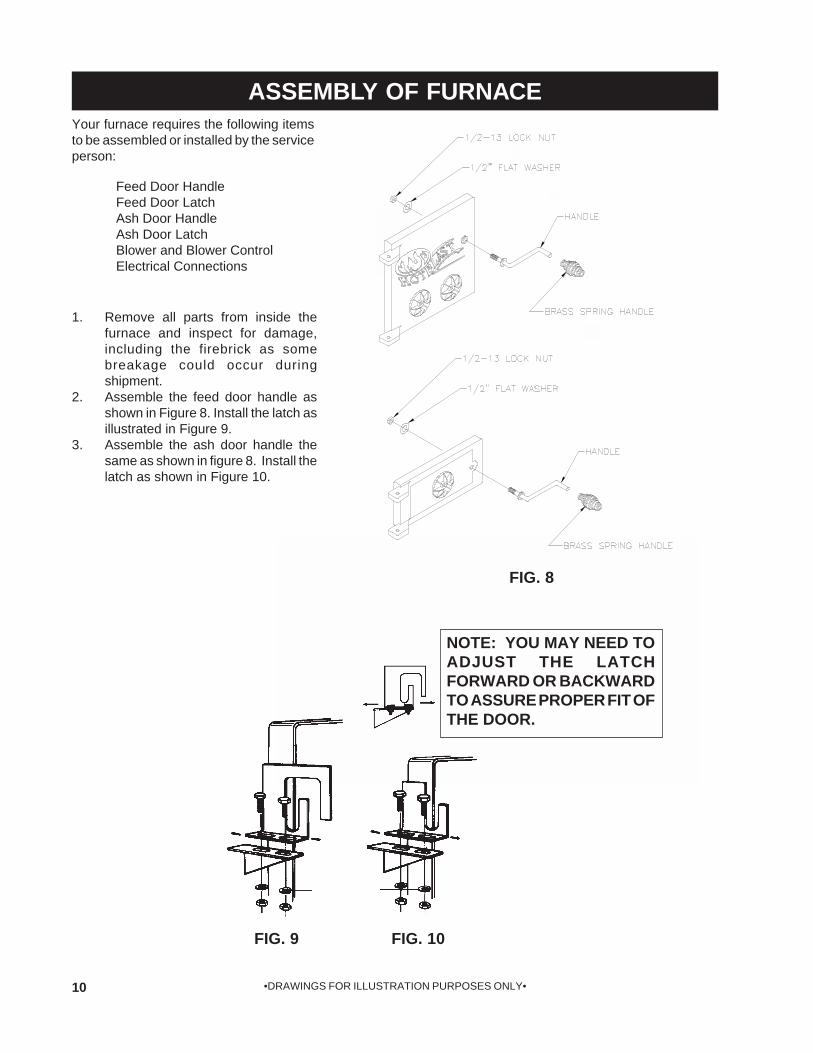
ASSEMBLY OF FURNACEYour furnace requires the following itemsto be assembled or installed by the serviceperson:
Feed Door HandleFeed Door LatchAsh Door HandleAsh Door LatchBlower and Blower ControlElectrical Connections
Remove all parts from inside thefurnace and inspect for damage,including the firebrick as somebreakage could occur duringshipment.Assemble the feed door handle asshown in Figure 8. Install the latch asillustrated in Figure 9.Assemble the ash door handle thesame as shown in figure 8. Install thelatch as shown in Figure 10.
1.
2.
3.
FIG. 9 FIG. 10
NOTE: YOU MAY NEED TOADJUST THE LATCHFORWARD OR BACKWARDTO ASSURE PROPER FIT OFTHE DOOR.
FIG. 8

11•DRAWINGS FOR ILLUSTRATION PURPOSES ONLY•
BLOWER & COMPONENT ASSEMBLY - FIG. 11
JUNCTION BOXMOUNTING
BRACKET
1. Attach the Honeywell Limit Control to the bracket as shown below, using (2) of the #12 x 3/4" Tek Screwsprovided in the parts bag.
2. Attach the 2x4 Junction Box to the bracket. Use (2) of the #12 x 3/4" Tek Screws provided. Also, attachthe flexible conduit from the Limit Control to the junction box using one of the Romax Conduit fitting andred anti-short bushing provided in the parts bag.
3. Unbox the blower and attach to the unit by sliding the flange on the blower between the cabinet back andthe unit bottom.
4. Now attach the blower to the unit by lining up the two holes and mounting blower with (2) 1/4-20 x 3/4"screws.
5. Attach the conduit from the blower to the junction box using one of the Romax Conduit fitting and redanti-short bushing.
6. Run the wires from the house supply into the junction box. Use the Romax Cable Clamp and red anti-short bushing provided.
7. Wire the components as shown in the wiring diagram on page 12.8. Replace junction box cover.
4
5
LIMIT CONTROLMOUNTING
BRACKET
3
2
1
CONDUIT
CONDUIT TWISTS INTOMOTOR HOUSING

12 •DRAWINGS FOR ILLUSTRATION PURPOSES ONLY•
MODEL 1200Q WIRING DIAGRAM - FIG. 12
LIMIT CONTROLB
LAC
K
WH
ITE
WH
ITE
BLA
CK
WHITE
BLACK
GREEN
2 x 4 JUNCTION BOX
BLOWER
TOHOUSESUPPLY
NOTE: GROUND HOUSESUPPLY TO INSIDE OFJUNCTION BOX.
13•DRAWINGS FOR ILLUSTRATION PURPOSES ONLY•
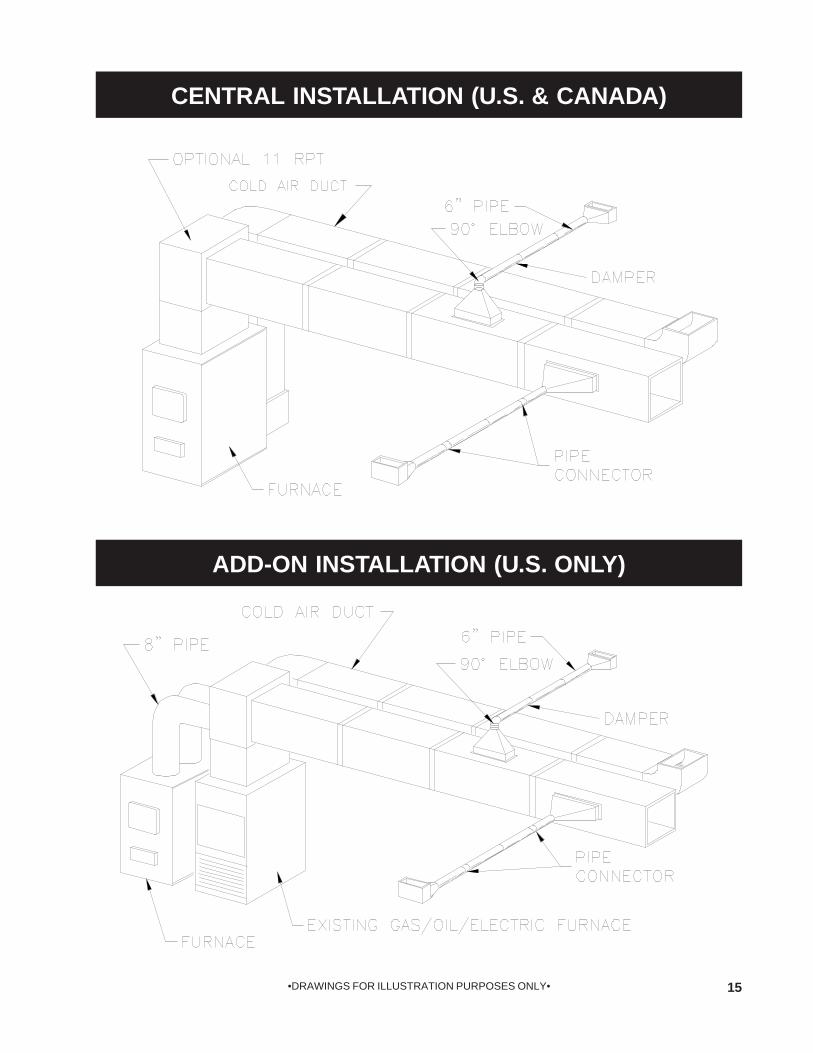
InstallationPlease see all methods of Installationin Appendix at the rear of this booklet. This is a furnace, not a free standing stove. You mustdirect heated air from 12" outlet away from the furnace,or it will not function properly.
1. This installation must be done by a qualifiedheating equipment installer.
2. The installation is to be done in compliance withNational Fire Protection Association installationstandards: No. 89M, 90B, 211, 70 (National ElectricCode) and Uniform Mechanical Code 913, 6-4, in thestates where applicable. (Their code offers connectingsmoke pipe connectors into chimney with other fuelburning appliances.)
3. Rooms large in comparison with size of theappliances:
a) A Wood Burning Furnace needs air for com-bustion and circulation to house.
b) Provision must be made to make up this air andnot starve gas or oil furnace of combustion air.
c) Have "Authority Having Jurisdiction"determine that air is of adequate makeup. (ReferenceN.F.P.A. Nos. 30 & 54, Code for Installation of Gas & OilEquipment)
4. Have "Authority Having Jurisdiction" to inspect allchimneys and installations for adequate venting and forcompliance with standard and local codes and regula-tions regarding installation of wood burning appli-ances.
5. Installation of Supplemental Heat Application toExisting Central System. (See Fig. 13 for typical in-stallation.)
a) Place Wood Burning Furnace so that thechimney connector will be as short as possible andavoiding unnecessary sharp turns in the smoke pipeconnector and the installation of devices that wouldcreate excessive resistance to the flow of flue gases.
b) Locate the Wood Burning Furnace as close aspractical to the existing central hot air heating system,maintaining clearances as stated on the label located onthe side of the furnace.
c) Clearances from combustible materials mustbe complied with as stated on the label below the fueldoor:
The installation must be made only on a noncombustiblefloor.
d) Install the smoke pipe connector to the chim-ney with 26-gauge pipe and elbows (to be purchasedseparately), maintaining the proper clearances forthe specific model. Make sure that the proper clear-ances as stated on the label and earlier in this manualare maintained. Seal the smoke pipe in the chimney withfurnace cement. (The chimney connector shall besecurely supported, and joints fastened with sheetmetal screws or rivets.)
e) Install 8" diameter heat pipe to plenum of thecentral hot air furnace. Use 26-guage pipe and con-nectors (to be purchased separately). (See Fig. 14) Ifcentral air conditioning is installed in the plenum, installheat pipe above the air conditioning unit. Secure heatpipe connection with supports and sheet metal screws.
f) Connect electrical supply in the electricaljunction box that is mounted on the back of the WoodBurning Furnace. See Wiring Diagram (Fig. 12). Removethe cover from electrical junction box connect powersupply wires to wires designated, using wire nuts. Thepower cord supplied may be used for installation, ifpermitted by local codes and regulations. If the powercord supplied cannot be used, the power supply wiringmust be 90 degrees Centigrade in a metal cable andshould be completed by a qualified installer complyingwith NFPA Standard No. 70 and local codes.
g) Optional Plenum Fan Control Switch (Part No.11PCS) is available for installation on the plenum ofcentral hot air heating furnace. The purpose of thisswitch is to activate the circulating fan of the central hotair heating furnace when the temperature in the plenumexceeds 120° Fahrenheit. The switch would activate thefan at 120° Fahrenheit, and would shut off the circulatingfan when the temperature in the plenum is reduced to100° Fahrenheit . This avoids overheating the plenum.
The electrical supply for operation of this fan controlswitch is to be obtained from same electrical supply asthe central hot air heating system. (See Fig. 14) Followthe instructions of the wiring diagram (Fig. 15). Do notmake connections across Limit Control in the furnace.
Make electrical connections in electrical junctionbox presently mounted on the furnace. Make electricalconnections in accordance with NFPA Standard No. 70and local codes in the power supply junction box (SeeFig. 15). The wiring to complete the connections shouldbe 18 AWG minimum copper and 90° Centigrade ina cable.
Unit to Combustible:Front: 48"Back: 30"Sides: 12"Plenum to Ceiling: 6"
Pipe to Combustible:Sides: 21"Back: 18"
NOTE: THE MAXIMUM STATIC PRESSURE AT THE CENTRAL OR COMBINED PLENUM MUST NOTEXCEED 0.12 INCHES WATER COLUMN.

14 •DRAWINGS FOR ILLUSTRATION PURPOSES ONLY•
POWER FAILURE INSTRUCTIONS:
Operation after loss of power
Remove filter if provided.Do not expect to keep home at normal temperatures.Do not load fuel above bottom of feed door.Set Fuel door and Ash door spin draft maximum closedper the factory installed stops.
1234
(U.S. ONLY)FIG. 13
15•DRAWINGS FOR ILLUSTRATION PURPOSES ONLY•
CENTRAL INSTALLATION (U.S. & CANADA)
ADD-ON INSTALLATION (U.S. ONLY)

16 •DRAWINGS FOR ILLUSTRATION PURPOSES ONLY•
ALTERNATIVE PARALLEL INSTALLATION WIRING DIAGRAM - FIG. 15
TO GAS/OIL/ELECTRICTRANSFORMER
HOTBLASTCOMBINATION CONTROL
LIMIT
FAN
JUMPER IN
H
H
POWERSUPPLY
GAS/OIL/ELECTRICPOWER SUPPLYJUNCTION BOX
CENTRALFURNACEBLOWERMOTOR
WOODFURNACEBLOWERMOTOR
CAUTION!DO NOT CONNECT
PLENUM FAN CONTROLSWITCH ACROSS FURNACE
LIMIT CONTROL.

17•DRAWINGS FOR ILLUSTRATION PURPOSES ONLY•
Your Hotblast Furnace is for burning wood only.
WOOD BURNING: (1)use Hardwood, 18" to 26", split and air dried (seasoned) for six months. (2) set thermostatto "HIGH" before opening feed door. (3) add wood to a convenient level.
CAUTIONNEVER USE GASOLINE, GASOLINE-TYPE LANTERNFUEL, KEROSENE, CHARCOAL LIGHTER FLUID, ORFLAMMABLE LIQUIDS TO START OR "FRESHEN UP" AFIRE IN THE FURNACE.
CAUTIONNEVER STORE FLAMMABLE LIQUIDS, ESPECIALLYGASOLINE, IN THE VICINITY OF THE FURNACE.
CAUTIONDO NOT OPERATE WITH THE FEED AND/OR ASHDOOR OPEN. THIS FURNACE IS DESIGNED FOR THER-MOSTATIC OPERATION. OPERATION WITH ANY OFTHESE DOORS OPEN WILL OVERHEAT AND DAMAGETHE FURNACE.
OPERATING INSTRUCTIONS
The temperature in the plenum of the warm air furnace atwhich the blower turns on or turns off, is controlled by thesetting of the pointers in the blower limit control (See Fig.12). These pointers may be adjusted through their entirerange of settings to achieve the desired warm air outputfrom the furnace. (See Fig. 16 Below)
1.
2.
3.
Move both pointers towards the right (counter clock-wise) - this increases the temperature setting at whichthe blower will turn on and off.Move both pointers towards the left (clockwise) - thisdecreases the temperature setting at which the blowerwill turn on and off.Move pointers away or apart from each other- thisincreases the time that the blower will run on eachwarm cycle. FIG. 16
ADJUSTING BLOWER LIMIT CONTROL SETTINGS
BLOWER LIMITPOINTER AND STOP
BLOWER FAN"ON" POINTER
BLOWER FAN"OFF" POINTER

18 •DRAWINGS FOR ILLUSTRATION PURPOSES ONLY•
Do not expect a furnace to draw. It is the chimney thatcreates the draft. Smoke spillage into the house or exces-sive build-up of water or creosote in the chimney is notfunctioning properly. Correct the problem before usingfurnace. Possible causes are:
The connector pipe may be pushed into the chimneytoo far, stopping the draft (Fig. 6).
Do not connect two furnaces or a stove and a furnaceinto the same chimney flue.
The chimney used for a furnace must not be used toventilate the cellar or basement. If there is a cleanoutopening at the base of the chimney, it must be closedtightly.
1.
2.
3.
If the chimney is operating too cool, water will condense inthe chimney and run back into the furnace. Creosote forma-tion will be rapid and may block the chimney. Operate thefurnace at a high enough fire to keep the chimney warmpreventing this condensation.
If the fire burns well but sometimes smokes or burns slowly,it may be caused by the chimney top being lower thananother part of the house or a nearby tree. The wind blowingover a house or a tree, falls on top of the chimney like waterover a dam, beating down the smoke. The top of thechimney should be at least 3 feet above the roof and be atleast 2 feet higher than any point of the roof within 10 feet(Fig. 5).
See page 28 for list of trouble shooting tips.
4.
5.
6.
A DRAFT READING OF .05 TO .06 W.C. IS SUGGESTED FOR PROPER BURNINGOF THIS UNIT WHEN USING WOOD.
SERVICE HINTS
Creosote and Soot - Formation and Need for Removal
When wood is burned slowly, it produces tar and otherorganic vapors, which combine with expelled moisture toform creosote. The creosote vapors condense in the rela-tively cool chimney flue of a slow-burning fire. As a result,creosote residue accumulates on the flue lining. Whenignited, this creosote makes an extremely hot fire.
The chimney should be inspected at least twice monthlyduring the heating season to determine if a creosote or sootbuild-up has occurred.
If soot or creosote has accumulated, it should be removed toreduce the risk of a chimney fire.
Chimney fires burn very hot. If the chimney catches fire, imme-diately call the fire department, then reduce the fire by closing theinlet air control. Pour a large quantity of coarse salt, baking sodaor cool ashes on top of the fire in the firebox.
CAUTIONA Chimney fire may cause ignition of wall studs or rafterswhich you thought were a safe distance from the chimney.If you have a chimney fire, have your chimney inspected bya qualified person before using again.
CHIMNEY MAINTENANCE
19•DRAWINGS FOR ILLUSTRATION PURPOSES ONLY•
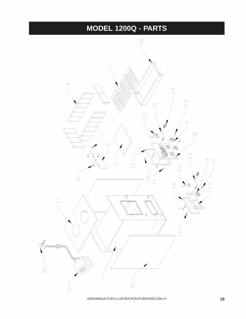
MODEL 1200Q - PARTS

20 •DRAWINGS FOR ILLUSTRATION PURPOSES ONLY•
MODEL 1200Q - PARTS LIST
KEY PART# DESCRIPTION QTY.
1 69121 FIREBOX WELDMENT 1
2 24576 BAFFLE 1
3 40288 GRATE 4
4 89066 FIREBRICK 18
5 23800 SMOKE CURTAIN 1
6 23787 SMOKE DOOR CLIP 2
7 83445 1/4-20 X 1-1/4 BOLT 2
N/S 83250 1/4-20 KEP NUT 2
8 24594 FEED DOOR 1
9 23859 DRAFT CAP 3
10 C20599 1/2-13 X 2-1/2 BOLT 2
11 83444 1/2-13 LOCK NUT 2
12 88082 3/4" ROUND ROPE GASKET 55IN.
13 24595 ASH DOOR 1
14 88082 3/4" ROUND ROPE GASKET 40IN.
15 83443 HINGE PIN 4
16 24568 CABINET SIDE 2
17 69151 CABINET TOP WELDMENT 1
18 69152 ASH PAN WELDMENT 1
19 69158 BLOWER ASSEMBLY 1
20 69129 FAN LIMIT ASSEMBLY 1
- 80145 LIMIT CONTROL 1
- 80061 3/8" FLEXIBLE CONDUIT .83FT
- 80061 3/8" FLEXIBLE CONDUIT .66FT
- 80086 CONDUIT FITTING 2
- 80362 3/8 ROMAX CABLE CONNECTOR 1
- 80125 2 X 4 JUNCTION BOX 1
- 80126 JUNCTION BOX COVER 1
21 24674 DOOR HANDLE 2
22 23786 DOOR LATCH 1
23 23823 ASH DOOR LATCH 1
24 89574 SPRING HANDLE 2
N/S = NOT SHOWN

21•DRAWINGS FOR ILLUSTRATION PURPOSES ONLY•
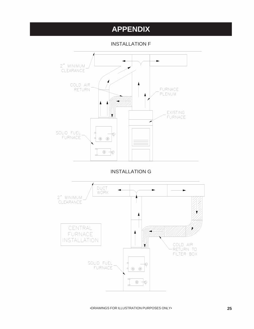
APPENDIX
INSTALLATION A
NOTE: ANTI-BACKDRAFT FLAPPERS OR BAFFLE ARE REQUIREDFOR THIS INSTALLATION.

22 •DRAWINGS FOR ILLUSTRATION PURPOSES ONLY•
APPENDIX
INSTALLATION B
NOTE: ANTI-BACKDRAFT FLAPPERS OR BAFFLE ARE REQUIREDFOR THIS INSTALLATION.

23•DRAWINGS FOR ILLUSTRATION PURPOSES ONLY•
APPENDIX
INSTALLATION C
NOTE: ANTI-BACKDRAFT FLAPPERS OR BAFFLE ARE REQUIREDFOR THIS INSTALLATION.

24 •DRAWINGS FOR ILLUSTRATION PURPOSES ONLY•
APPENDIX
INSTALLATION D(U.S. ONLY)
INSTALLATION E(U. S. ONLY)
25•DRAWINGS FOR ILLUSTRATION PURPOSES ONLY•
APPENDIX
INSTALLATION F
INSTALLATION G

26 •DRAWINGS FOR ILLUSTRATION PURPOSES ONLY•
NOTES
27•DRAWINGS FOR ILLUSTRATION PURPOSES ONLY•
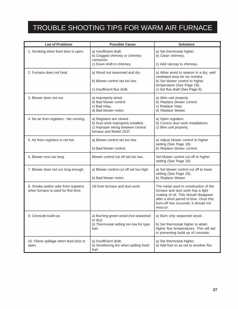
List of Problems Possible Cause Solutions
1. Smoking when feed door is open.
2. Furnace does not heat.
3. Blower does not run.
4. No air from registers - fan running.
5. Air from registers is not hot.
6. Blower runs too long.
7. Blower does not run long enough.
8. Smoke and/or odor from registerswhen furnace is used for first time.
9. Creosote build-up.
10. Flame spillage when feed door isopen.
a) Insufficient draft.b) Clogged chimney or chimneyconnector.c) Down draft in chimney.
a) Wood not seasoned and dry.
b) Blower control set too low.
c) Insufficient flue draft.
a) Improperly wired.b) Bad blower control.c) Bad relay.d) Bad blower motor.
a) Registers are closed.b) Duct work improperly installed.c) Improper wiring between centralfurnace and Model 1537.
a) Blower control set too low.
b) Bad blower control.
Blower control cut off set too low.
a) Blower control cut off set too high.
b) Bad blower motor.
Oil from furnace and duct work.
a) Burning green wood (not seasonedor dry).b) Thermostat setting too low for typefuel.
a) Insufficient draft.b) Smothering fire when adding freshfuel.
a) Set thermostat higher.b) Clean chimney.
c) Add raincap to chimney.
a) Allow wood to season in a dry, wellventilated area for six months.b) Set blower control to highertemperature (See Page 18).c) Set flue draft (See Page 9).
a) Wire unit properly.b) Replace blower control.c) Replace relay.d) Replace blower.
a) Open registers.b) Correct duct work installations.c) Wire unit properly.
a) Adjust blower control to highersetting (See Page 18).b) Replace blower control.
Set blower control cut off to highersetting (See Page 18)
a) Set blower control cut off to lowersetting (See Page 18).b) Replace blower.
The metal used in construction of thefurnace and duct work has a lightcoating of oil. This should disappearafter a short period of time. Once thisburn-off has occurred, it should notreoccur.
a) Burn only seasoned wood.
b) Set thermostat higher to attainhigher flue temperatures. This will aidin preventing build-up of creosote.
a) Set thermostat higher.b) Add fuel so as not to smother fire.
TROUBLE SHOOTING TIPS FOR WARM AIR FURNACE

28 •DRAWINGS FOR ILLUSTRATION PURPOSES ONLY•
THIS MANUAL WILL HELP YOU OBTAIN EFFICIENT, DEPEND-ABLE SERVICE FROM YOUR HOTBLAST FURNACE, AND EN-ABLE YOU TO ORDER REPAIR PARTS CORRECTLY.
KEEP THIS MANUAL IN A SAFE PLACE FOR FUTURE REFER-ENCE.
WHEN WRITING, ALWAYS GIVE THE FULL MODEL NUMBERWHICH IS ON THE NAMEPLATE ATTACHED TO THE HEATER.
WHEN ORDERING REPAIR PARTS, ALWAYS GIVE THEFOLLOWING INFORMATION AS SHOWN IN THIS LIST:
1. THE PART NUMBER
2. THE PART DESCRIPTION
3. THE MODEL NUMBER: 1200Q
4. THE SERIAL NUMBER:____________________
HOW TO ORDER REPAIR PARTS
UNITED STATES STOVE COMPANY227 INDUSTRIAL PARK ROAD
P.O.BOX 151SOUTH PITTSBURG, TN 37380
(423) 837-2100COMPANY
UNITEDSTATES STOVE
CSSUWARNOCK HERSEY
R