solid oxide fuel cells produced by atmospheric plasma...
TRANSCRIPT
Solid Oxide Fuel Cells produced by Atmospheric Plasma Spray technology: Structural and electrochemical characterization.
M. Torrell, I.G. Cano, J.M. Miguel , J.M. Guilemany Thermal Spray Center (CPT). Universitat de Barcelona, Barcelona 28080, Spain
*e-mail: [email protected]
M. A. Laguna-Bercero, V. M. Orera
Instituto de Ciencia de Materiales de Aragón, ICMA, CSIC – Universidad de Zaragoza, 50009 Zaragoza, Spain
Abstract Ceramic materials have been used in a wide range of application. One of the most innovative applications is their use to perform Solid Oxide Fuel Cells. The aim of this work is to elucidate how to obtain a complete self-assembled SOFC (supported by electrolyte) using Atmospheric Plasma Spray (APS) to spray the three different ceramic layers. One of the main problems of SOFC production is the high costs of the process that can be reduced performing the three ceramic of a SOFC by APS technology. Anode (YSZ-NiO), Cathode (LSM) and Electrolyte (YSZ) can be obtained by APS with reasonable good behavior in terms of SOFC efficient. Another problem is the three layers assembling and adhesion, the use of gradual transition layers by APS improve the adhesion and assembling of the layers. Chemical and structural characterization of the feedstock powders and obtained ceramic layers was done by Laser Scattering, XRD, SEM and Confocal microscopy and correlated with the efficiency of attained APS-SOFC components.
Introduction
Solid Oxide Fuel Cells (SOFC) represents one of the most innovative applications in the ceramic materials field on the last years (Ref 1). Transformation of fuel chemical energy into power by a direct conversion leads by a multilayered ceramic piece awakes great interests in multiple fields, from the auxiliary power units (APU) (Ref 2, 3) to the heat and power combined devices for residential applications (Ref 4, 5). Low efficiency, high degradation rates and relative high cost of production are barrier factors on the SOFCs’ comercialization. Thermal Spray technologies, and specially APS, offer a relatively inexpensive technology to produce ceramic layers with a high control on the SOFC key factors such as porosity, thickness and different layer assembling (Ref 6). Performed SOFC operates at high temperatures that promote degradation mechanisms that shortened SOFCs lifetime. Electrolyte layer is based on ceramic zirconia stabilized with 8%mol yttria (YSZ) which stabilize Cubic YSZ phase giving a good ionic conductivity at high temperatures and ensure a dense and gas-tight membrane. Electrodes have to fill several requirements to be used on SOFC systems. First requirements are to have fuel and oxidative gas flowability (porosity), and also high conductivity. The coefficient of thermal expansion has to
match with the other components. The anode is stable in reducing atmospheres and the cathode in oxidizing atmospheres. Both of them have to be compatible with the electrolyte. Typically a Ni/YSZ cermets is used as anode that is obtained after the NiO reduction by the fuel flow. This reduction produces a volume change on the layer improving the porosity and permeability of the anode layer. The cathode is LSM, a Lanthanum, Stroncium and Magnesium perouskite with high temperature resistance, good conductivity and compatible with the electrolyte. APS presents the challenging opportunity to perform electrodes and electrolyte using the same technology and assures a good structure and match between layers. It is easy to minimize mismatch problems performing gradient layers that avoid thermal expansion cracking. The use of fine gradient layers of the electrolyte layer (YSZ) and cathode electrode LSM (cathode) as a transition interlayer, promotes a better behavior to produce these grandient composite layers is a quite easy process using APS technologies. Minimize electrolyte porosity and cracking using the conventional APS technology, and characterize the influence on the production process on the final efficiency, is the aim of the present work. The main target is to produce SOFC by APS with a relative high efficiency/cost ratio.
Experimental Process
Atmospheric plasma spray has been selected as deposition technique for all the Solid Oxide Fuel Cell layers due to its high spray temperature and low cost production. Anode processing NiO-YSZ was used as raw material for the production of the anode layer. After the reduction of the sprayed NiO-YSZ during the first hours of use, the Ni-YSZ layer is obtained. Reduction of NiO to Ni produces a drop on the volume, leading to an improvement of the layer porosity and fuel permeability. Ni-YSZ also shows a good thermal expansion avoiding mismatch problems with the other layers of the component. Anode layer is where the fuel oxidation takes place. This fuel can be hydrogen or hydrocarbonate fuel. Main requirements for a SOFC anode layer are a good electric conductivity, high porosity, low reactivity with fuel and catalytic activity (Ref 7) [7].
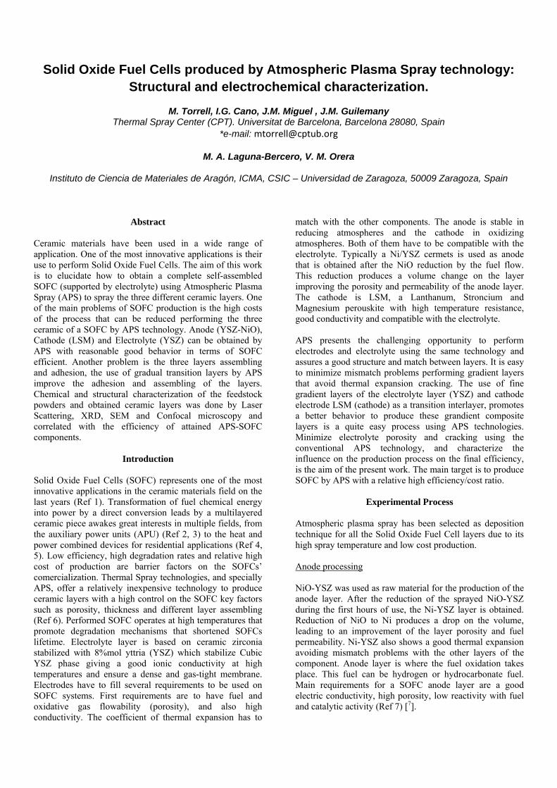
Anode layer was produced, as the rest of layers, by APS, using a DJ-2700 Sulzer-Metco gun. Used feedstock powder was a spherical powder with a size distribution -95+5 µm obtained by agglomeration process. Figure 1 shows the free surface of the NiO-YSZ powder. Chemical composition is 32 wt% YSZ 68 wt% NiO. Size distribution and XRD are presented in figures 2 and 3 respectively.
Figure 1: NiO-YSZ powder used to produce the anode layer.
Figure 2: Particle size distribution for NiO-YSZ powder.
Figure 3: XRD pattern for NiO-YSZ powder.
Electrolyte processing Yttria stabilized Zirconia (YSZ) is the most used material as electrolyte in SOFC. The main handicap found in this work is to produce a YSZ dense layer by conventional APS for SOFC application. YSZ is used due its chemical stability ad ionic conductivity in a high range of conditions (Ref 7, 8, 9)
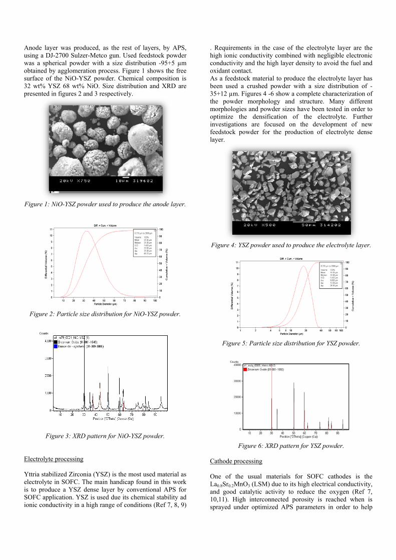
. Requirements in the case of the electrolyte layer are the high ionic conductivity combined with negligible electronic conductivity and the high layer density to avoid the fuel and oxidant contact. As a feedstock material to produce the electrolyte layer has been used a crushed powder with a size distribution of -35+12 µm. Figures 4 -6 show a complete characterization of the powder morphology and structure. Many different morphologies and powder sizes have been tested in order to optimize the densification of the electrolyte. Further investigations are focused on the development of new feedstock powder for the production of electrolyte dense layer.
Figure 4: YSZ powder used to produce the electrolyte layer.
Figure 5: Particle size distribution for YSZ powder.
Figure 6: XRD pattern for YSZ powder. Cathode processing One of the usual materials for SOFC cathodes is the La0.8Sr0.2MnO3 (LSM) due to its high electrical conductivity, and good catalytic activity to reduce the oxygen (Ref 7, 10,11). High interconnected porosity is reached when is sprayed under optimized APS parameters in order to help

the oxygen flow. In terms of compatibility with the YSZ electrolyte is optimal at working temperatures. The feedstock used powder was a spherical powder that presents a size distribution of -65+10 µm is observed on the SEM free surface image presented on figure 7. This powder is produced by the nanoparticles agglomeration leading to porous fine particles with an average size of 32 µm. Described powder morphology helps to keep porosity to the final obtained cathode layer. Figures 8 and 9 show the size distribution and XRD analysis respectively.
Figure 7: LSM powder used to produce the anode layer.
Figure 8: Particle size distribution for LSM powder.
Figure 9: XRD pattern of LSM powder.
Three layers SOFC piece production The three layers of the Solid Oxide Fuel Cell have been performed by APS. Each layer (anode, electrolyte and cathode) have their own optimal spray conditions. The electrolyte must be dense meanwhile the porosity of the electrodes is a must for the gas flow penetration from the
surface to the electrolyte-electrode interface where the reactions take place. APS spray process also improves the layers cohesion and thermal failure resistance (Ref 12) . A prerequisite for the deposition of dense ceramic layers by thermal spray processes is the complete melting of the powder particles during spraying (Ref 13, 14) .The three layers have been deposited over aluminum substrate that is removed by chemical etching to obtain the self assembled SOFC. Table I summarizes the optimal conditions to perform each SOFC layer. Different thicknesses are achieved for the different layers. Cathode conditions have been used to produce a gradual interlayer between cathode and electrolyte in order to improve interlayer’s mismatch.
Table I. Spray conditions of the three ceramic layers Anode Electrolyte Cathode Spray distance
(mm) 80-90 100-110 115-125
Intensity (A) 500-525 600-650 500-550 Layers 10 20 6
Characterization techniques. Microstructure of powders and coatings was studied using a scanning electron microscope (SEM) JEOL 5310 and FESEM Quanta 200 FEI. XRD patterns were used to identify phases present in the coatings after the spraying process as well as the grade of cristallinity of the layer. An accurate phase analysis of the coatings was performed specially for the electrolyte produced with different cooling systems added to the APS system. Electrolyte porosity has been characterized by Confocal Espectral Microscopy with a Leica TCS-SPE, considering the deep of the porosity to evaluate the interconnectivity of the electrolyte porous. ASTM 633 standard were used to determine the interlayer cohesion between the electrolyte and the electrodes. Preliminary tests of the SOFC efficiency to corroborate the activity of the produced pieces has been done. Samples were sealed into an alumina tube using Omegabond 700 high temperature sealant (Omega Engineering Inc., Stanford, US). The measurements were performed using four Pt wires to measure voltage and current. A Pt mesh was attached to the electrodes using spring loads. j-V measurements were recorded using a VSP Potentiostat/Galvanostat (Princeton Applied Research, Oak Ridge, US) at temperatures between 700 and 900 ºC using 3%H2O/97%H2 at the anode (Q = 50 ml/min) and synthetic air at the cathode site (Q = 100 ml/min).
Experimental Results Structural characterization of SOFC pieces performed by APS. Figure 10 shows the structure of obtained pieces where it can be observed the stable configuration of three layers. SEM cross section image of the figure 10 shows the three layers piece. On the top is the NiO-YSZ anode, then the electrolyte followed by the gradual cathode LSM layer. The
thickness of each layer is around; 70 microns for the anode, 160 microns for the electrolyte and 70 microns for the cathode. As it can be seen the interfaces between the layers are perfectly cohered. The porosity of the anode will be increased in service for the reduction of the NiO to Ni in presence of H2 as fuel. The studies of present phases have been carried out by XRD indexing YSZ, NiO and LSM as major crystalline phases (figure 11). Cohesion between three layers has been characterized by the adhesion test, were a very good matching of the layers has been obtained. No descohesion or fracture of the layers has been reported. Descohesion mechanism has been placed in the substrate cathode interface, achieving 15 MPa of traction loads.
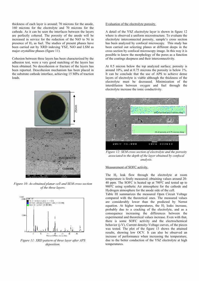
Evaluation of the electrolyte porosity. A detail of the YSZ electrolyte layer is shown in figure 12 where is observed a uniform microstructure. To evaluate the electrolyte interconnected porosity, sample’s cross section has been analyzed by confocal microscopy. This study has been carried out selecting planes at different deeps in the cross section by confocal microscopy image. In this way it is possible to know the morphology of the pores as a function of the coatings deepness and their interconnectivity. At 0.5 micron below the top analyzed surface; porosity is around 10%, and at 0.75 microns the porosity is below 1%. It can be conclude that the use of APS to achieve dense layers of electrolyte is viable although the thickness of the electrolyte must be decreased. Minimization of the interdifusion between oxygen and fuel through the electrolyte increase the ionic conductivity.
Figure 12: SEM cross section of electrolyte and the porosity associated to the depth of the layer obtained by confocal
analysis. Measurement of SOFC activity. The H2 leak flow through the electrolyte at room temperature is firstly measured; obtaining values around 20-40 ppm. The SOFC is heated up at 700ºC and tested up to 900ºC using synthetic Air atmosphere for the cathode and Hydrogen atmosphere for the anode side of the cell. Table III summarizes the measured Open Circuit Voltage compared with the theoretical ones. The measured values are considerably lower than the predicted by Nernst equation. At higher temperatures, the H2 leaks increase, probably due to a cracking of the electrolyte, and as a consequence increasing the differences between the experimental and theoretical values increase. Even with that, there is some SOFC activity and the electrochemical behavior (j-V), Current density-Voltage curves, of the pieces was tested. The plot of the figure 13 shows the attained results, showing low OCV. It can also be observed an increase of performance when increasing the temperature, due to the better conduction of the YSZ electrolyte at high temperatures.
Figure 10: As-obtained planar cell and SEM cross section of the three layers.
Figure 11: XRD pattern of three layer after APS deposition.
25mm
10% of porosity at 0.5 microns deep
1% of porosity at 0.75 microns deep
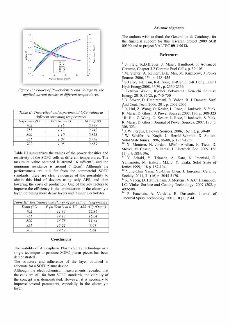
Figure 13: Values of Power density and Voltage vs. the
applied current density at different temperatures.
Table II: Theoretical and experimental OCV values at
different operating temperatures Temperature (ºC) OCV Nernst( V) OCV exp (V)
702 1.16 0.989 751 1.13 0.942 800 1.10 0.853 851 1.07 0.758 902 1.05 0.689
Table III summarizes the values of the power densities and resistivity of the SOFC cells at different temperatures. The maximum value obtained is around 16 mWcm-2, and the minimum resistance is around 7 Ωcm2. Although the performances are still far from the commercial SOFC standards, there are clear evidences of the possibility to obtain this kind of devices using only APS, and then lowering the costs of production. One of the key factors to improve the efficiency is the optimization of the electrolyte layer, obtaining more dense layers and thinner electrolytes. Table III: Resitstance and Power of the cell vs. temperature
Temp (ºC) P (mWcm-2) at 0.5V ASR (IV) (Ωcm2) 702 11.34 22.36 751 14.13 16.04 800 15.75 11.64 851 15.22 9.01 902 14.52 6.84
Conclusions
The viability of Atmospheric Plasma Spray technology as a single technique to produce SOFC planar pieces has been demonstrated. The structure and adherence of the layer obtained is adequate for a SOFC planar device. Although the electrochemical measurements revealed that the cells are still far from SOFC standards, the viability of the concept was demonstrated. However, it is necessary to improve several parameters, especially in the electrolyte layer.
Acknowledgments The authors wish to thank the Generalitat de Catalunya for the financial support for this research project 2009 SGR 00390 and to project VALTEC 09‐1‐0013.
References
1 J. Fleig, K.D.Kreuer, J. Maier, Handbook of Advanced Ceramic, Chapter 3.2 Ceramic Fuel Cells, p. 59-105 2 M. Stelter, A. Reinert, B.E. Mai, M. Kuznecov, J Power Sources 2006, 154, p. 448–455 3 SB Lee, T-H Lim, R-H Song, D-R Shin, S-K Dong, Inter J Hydr Energy2008, 33(9) , p. 2330-2336 4 Tetsuya Wakui, Ryohei Yokoyama, Ken-ichi Shimizu Energy 2010, 35(2), p. 740-750 5 D. Stöver, D. Hathiramani, R. Vaben, R. J. Damani. Surf. And Coat. Tech. 2006, 201, p. 2002-2005 6 R. Hui, Z. Wang, O. Kesler, L. Rose, J. Jankovic, S. Yick, R. Maric, D. Ghosh. J. Power Sources 2007, 170, p. 308-323 7 R. Hui, Z. Wang, O. Kesler, L. Rose, J. Jankovic, S. Yick, R. Maric, D. Ghosh. Journal of Power Sources. 2007, 170, p. 308-323. 8 J. W. Fergus, J. Power Sources, 2006, 162 (1), p. 30-40 9 W. Schäfer, A. Kocjh. U. Herold-Schmidt, D. Stolten. Solid State Ionics. 1996, 86-88, p. 1235-1239. 10 X. Montero, N. Jordan, J.Pirón-Abellan, F. Tietz, D. Stöver, M. Cassir, J. Villareal. J. Electroch. Soc, 2009, 156 (1) p. b188-b196. 11 Y. Sakaki, Y. Takaeda, A. Kato, N. Imanishi, O. Yamamoto, M. Hattori, M.Lio, Y. Esaki. Solid State of Ionics 1999, 118 p. 187-194. 12 Yung-Chin Yang, Yu-Chun Chen. J. European Ceramic Society. 2011, 31 (16) p. 3045-3170. 13 R. Vaben, D. Hathiramani, J. Mertens, V.A.C. Haanappel, I.C. Vinke. Surface and Coating Technology. 2007 (202, p 499-508. 14 P. Fauchais, A. Vardelle, B. Dussoubs. Journal of Thermal Spray Technology. 2001, 10 (1), p 44