solidworks · solidworks teacher guide and student courseware 47 3 lesson 3: the 40-minute running...
TRANSCRIPT

SolidWorks®
SolidWorks Teacher Guide and Student Courseware
SolidWorks Corporation Outside the U.S.: +1-978-371-5011300 Baker Avenue Fax: +1-978-371-7303Concord, Massachusetts 01742 USA Email: [email protected] +1-800-693-9000 Web: http://www.solidworks.com/education

© 1995-2005, SolidWorks Corporation 300 Baker AvenueConcord, Massachusetts 01742 USAAll Rights Reserved
SolidWorks Corporation is a Dassault Systemes S.A. (Nasdaq:DASTY) company.The information and the software discussed in this document are subject to change without notice and should not be considered commitments by SolidWorks Corporation. No material may be reproduced or transmitted in any form or by any means, electronic or mechanical, for any purpose without the express written permission of SolidWorks Corporation.The software discussed in this document is furnished under a license and may be used or copied only in accordance with the terms of this license. All warranties given by SolidWorks Corporation as to the software and documentation are set forth in the SolidWorks Corporation License and Subscription Service Agreement, and nothing stated in, or implied by, this document or its contents shall be considered or deemed a modification or amendment of such warranties.SolidWorks® is a registered trademark of SolidWorks Corporation.SolidWorks 2005 is a product name of SolidWorks Corporation.FeatureManager® is a jointly owned registered trademark of SolidWorks Corporation.Feature Palette™, PhotoWorks™, and PDMWorks™ are trademarks of SolidWorks Corporation. ACIS® is a registered trademark of Spatial Corporation.FeatureWorks® is a registered trademark of Geometric Software Solutions Co. Limited.GLOBEtrotter® and FLEXlm® are registered trademarks of Globetrotter Software, Inc.Other brand or product names are trademarks or registered trademarks of their respective holders.
COMMERCIAL COMPUTER SOFTWARE - PROPRIETARYU.S. Government Restricted Rights. Use, duplication, or disclosure by the government is subject to restrictions as set forth in FAR 52.227-19 (Commercial Computer Software - Restricted Rights), DFARS 227.7202 (Commercial Computer Software and Commercial Computer Software Documentation), and in the license agreement, as applicable.Contractor/Manufacturer:SolidWorks Corporation, 300 Baker Avenue, Concord, Massachusetts 01742 USAPortions of this software are copyrighted by and are the property of Electronic Data Systems Corporation or its subsidiaries, copyright© 2005Portions of this software © 1999, 2002-2005 ComponentOnePortions of this software © 1990-2005 D-Cubed Limited.Portions of this product are distributed under license from DC Micro Development, Copyright © 1994-2002 DC Micro Development, Inc. All rights reservedPortions © eHelp Corporation. All rights reserved.Portions of this software © 1998-2005Geometric Software Solutions Co. Limited.Portions of this software © 1986-2005mental images GmbH & Co. KGPortions of this software © 1996Microsoft Corporation. All Rights Reserved.Portions of this software © 2001, SIMULOG.Portions of this software © 1995-2005Spatial Corporation.Portions of this software © 2005, Structural Research & Analysis Corp.Portions of this software © 1997-2005 Tech Soft America.Portions of this software © 1999-2005Viewpoint Corporation.Portions of this software © 1994-2005, Visual Kinematics, Inc.All Rights Reserved
U.S. Patents 5,815,154; 6,219,049; 6,219,055
Document Number: PME0213-ENG

SolidWorks Teacher Guide iii
Introduction viiLesson 1: Using the Interface 1Lesson 2: Basic Functionality 17Lesson 3: The 40-Minute Running Start 45Lesson 4: Assembly Basics 63Lesson 5: Toolbox Basics 93Lesson 6: Drawing Basics 115Lesson 7: eDrawing Basics 143Lesson 8: Design Tables 165Lesson 9: Revolve and Sweep Features 187Lesson 10: Loft Features 211Lesson 11: Visualization 229Glossary 251
Contents

SolidWorks Teacher Guide and Student Courseware 47
3 Lesson 3: The 40-Minute Running Start
Goals of This Lesson
Students will be able to create and modify the following part:
Before Beginning This Lesson
Complete the previous lesson — Basic Functionality.
Resources for This Lesson
This lesson plan corresponds to Lesson 1 – Parts in the SolidWorks Online Tutorials. For more information about the Online Tutorials, See “Online Tutorials” on page v.

Lesson 3: The 40-Minute Running Start
48 SolidWorks Teacher Guide and Student Courseware
Review of Lesson 2: Basic Functionality
Questions for Discussion1 A SolidWorks 3D model consists of three documents. Name the three documents.
Answer: Part, Assembly and Drawing.2 Parts are built from features. What are features?
Answer: Features are the shapes (bosses, cuts and holes) and the operations (fillets, chamfers and shells) that you use to build a part.
3 Name the features that are used to create the box in Lesson 1. Answer: Extruded Boss, Fillet, Shell, and Extruded Cut.
4 What is the base feature of the box? Answer: The base feature is the first feature of the box. The base feature is the foundation of the part. The base feature geometry for the box is an extrusion. The extrusion is named Extrude1. The base feature represents the general shape of the box.• Use a cardboard box to illustrate the
Base feature. 5 Why did you use the Fillet feature?
Answer: The fillet feature rounds the sharp edges and faces. The result of using the fillet feature created the rounded edges of the box.
6 Why did you use the Shell feature? Answer: The shell feature removes material. The result of using the shell feature created a hollow block from a solid block.
7 How do you create the Base feature?Answer: To create a solid Base feature:• Sketch a rectangular profile on a flat 2D plane. • Extrude the profile perpendicular to the sketch plane.
8 What would have happened if the Shell feature was created before the Fillet feature?Answer: The inside corners of the box would be sharp instead of rounded.
1. Base Feature 2. Fillet Feature
4. Cut Feature3. Shell Feature

Lesson 3: The 40-Minute Running Start
SolidWorks Teacher Guide and Student Courseware 49
Outline of Lesson 3
In Class Discussion — Base Features
Active Learning Exercise — Create a Part
Exercises and Projects — Modifying a Part• Converting Dimensions• Calculating the Modification• Modifying the Part• Calculating Material Volume• Calculating the Volume of the Base feature
Exercises and Projects — Creating a CD Jewel Case and Storage Box• Measuring the CD Jewel Case• Rough Sketch of the Jewel Case• Calculate the Overall Case Capacity• Calculate the Outside Measurements of the CD Storage Box• Creating the CD Jewel Case and Storage Box
More to Explore — Modeling More Parts
Lesson Summary

Lesson 3: The 40-Minute Running Start
50 SolidWorks Teacher Guide and Student Courseware
In Class Discussion — Base Features
Select a simple object in the classroom, a piece of chalk or board eraser.
Ask the students to describe the Base feature of these objects.
How would you create the additional features for these objects?
Answer
Chalk:
Sketch a circular 2D profile.
Extrude the 2D profile. The extruded 2D profile creates the Base feature. The Base feature is named Extrude1.
Select the circular edge on the Base feature. Create a Fillet feature. The Fillet feature removes sharp edges.
Board Eraser:
Sketch a rectangular 2D profile.
Extrude the 2D sketch. This creates the Base feature.
Select the 4 corners on the Base feature. Create a Fillet feature to remove the sharp edges.
Note: You would probably not want to use the Fillet feature for a new piece of chalk.

Lesson 3: The 40-Minute Running Start
SolidWorks Teacher Guide and Student Courseware 51
Active Learning Exercise — Create a Part
Follow the instructions in Lesson 1 – Parts of the SolidWorks Online Tutorial. In this lesson you will create the part shown at the right. The part name is Tutor1.sldprt.
5 Minute Assessment – Answer Key
1 What features did you use to create Tutor1? Answer: Extruded Boss, Fillet, Shell and Extruded Cut.
2 What does the Fillet feature do?Answer: The Fillet feature rounds sharp edges and faces
3 What does the Shell feature do?Answer: The Shell feature removes material from the selected face.
4 Name three view commands in SolidWorks.Answer: Zoom to Fit, Rotate View, and Pan.
5 Where are the display buttons located?Answer: The display buttons are located on the View toolbar.
6 Name the three SolidWorks default planes.Answer: Front, Top, and Right.
7 The SolidWorks default planes correspond to what principle drawing views?Answer:
• Front = Front or Back view• Top = Top or Bottom view• Right = Right or Left view
8 True or False. In a fully defined sketch, geometry is displayed in black. Answer: True.
9 True or False. It is possible to make a feature using an over defined sketch.Answer: False.
10 Name the primary drawing views used to display a model.Answer: Top, Front, Right and Isometric views.

Lesson 3: The 40-Minute Running Start
52 SolidWorks Teacher Guide and Student Courseware
Exercises and Projects — Modifying the Part
Task 1— Converting Dimensions
The design for Tutor1 was created in Europe. Tutor1 will be manufactured in the US. Convert the overall dimensions of Tutor1 from millimeters to inches.
Given:
Conversion: 25.4 mm = 1 inch
Base width = 120 mm
Base height = 120 mm
Base depth = 50 mm
Boss depth = 25 mm
Answer:
Overall depth = Base depth + Boss depthOverall depth = 1.97” + 0.98” = 2.95”
Overall dimensions = Base width x Base height x DepthOverall dimensions = 4.72” x 4.72” x 2.95”
In Class Demonstration:
SolidWorks supports both metric and English units. Demonstrate the software conversion from metric to English units. 1 Click Tools, Options.2 Click the Document Properties tab.3 Click Units. 4 Click Inches from the Linear units
list. Click OK.5 Double-click the Tutor1 features to
display the dimensions.• Base width = 4.72”• Base height = 4.72”• Base depth = 1.97”• Boss depth = 0.98”
Note: Units are in Millimeters
Note: Units are in Inches

Lesson 3: The 40-Minute Running Start
SolidWorks Teacher Guide and Student Courseware 53
Task 2— Calculating the Modification
The current overall depth of Tutor1 is 75 mm. Your customer requires a design change. The new required overall depth is 100 mm. The Base depth must remain fixed at 50 mm. Calculate the new Boss depth.
Given:
New overall depth = 100 mm
Base depth = 50 mm
Answer:
Overall depth = Base depth + Boss depthBoss depth = Overall depth - Base depthBoss depth = 100mm - 50 mmBoss depth = 50 mm
Task 3— Modifying the Part
Using SolidWorks, modify Tutor1 to meet the customer’s requirements. Change the depth of the Boss feature such that the overall depth of the part equals 100 mm. Save the modified part under a different name.
Answer:
1 Double-click on the Extrude2 feature.
2 Double-click on the 25 mm depth dimension.3 In the Modify dialog, enter the value 50mm.4 Press Enter.

Lesson 3: The 40-Minute Running Start
54 SolidWorks Teacher Guide and Student Courseware
5 Click Rebuild.
6 Click File, Save As to create block100.When you use File, Save As, you save a copy of the document with a new name or path. You can create a new folder in the Save As dialog box if needed. After you use File, Save As, you are working in the new document. The original document is closed without saving.If you click the Save as copy check box you will save a copy of the document, with a new name, without replacing the active document. You continue to work in the original document.
Task 4— Calculating Material Volume
Material volume is an important calculation for designing and manufacturing parts. Calculate the volume of the Base feature in mm3 for Tutor1.
Answer:
Volume = Width x Height x DepthVolume = 120mm x 120mm x 50mm = 720,000 mm3
Task 5— Calculating the Volume of the Base feature
Calculate the volume of the Base feature in cm3.
Given:
1cm = 10mm
Answer:
Volume = Width x Height x DepthVolume = 12cm x 12cm x 5cm = 720cm3

Lesson 3: The 40-Minute Running Start
SolidWorks Teacher Guide and Student Courseware 55
Exercises and Projects — Creating a CD Jewel Case and Storage Box
You are part of a design team. The project manager has provided the following design criteria for a CD storage box:
The CD storage box is constructed of a polymer (plastic) material.
The storage box must hold 25 CD jewel cases.
The title of the CD must be visible when the jewel case is positioned in the storage box.
The wall thickness of the storage box is 1cm.
On each side of the storage box, there must be 1cm clearance between the jewel case and the inside of the box.
There must be 2cm clearance between the top of the CD cases and the inside of the storage box.
There must be 2cm clearance between the jewel cases and the front of the storage box.
Task 1 — Measuring the CD Jewel Case
Measure the width, height, and depth of one CD jewel case. What are the measurements in centimeters?
Answer:
Approximately 14.2cm x 12.4cm x 1cm
Task 2— Rough Sketch of the Jewel Case
Using paper and pencil, manually sketch the CD jewel case. Label the dimensions.
Lesson 3: The 40-Minute Running Start
56 SolidWorks Teacher Guide and Student Courseware
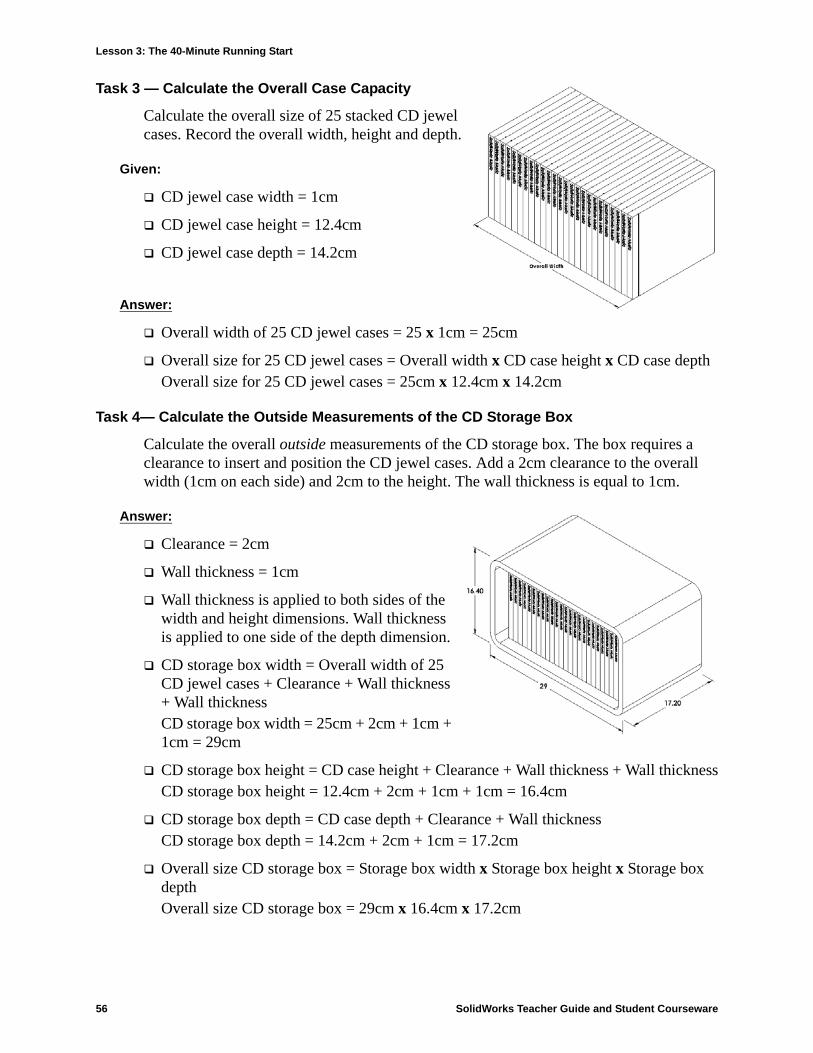
Task 3 — Calculate the Overall Case Capacity
Calculate the overall size of 25 stacked CD jewel cases. Record the overall width, height and depth.
Given:
CD jewel case width = 1cm
CD jewel case height = 12.4cm
CD jewel case depth = 14.2cm
Answer:
Overall width of 25 CD jewel cases = 25 x 1cm = 25cm
Overall size for 25 CD jewel cases = Overall width x CD case height x CD case depthOverall size for 25 CD jewel cases = 25cm x 12.4cm x 14.2cm
Task 4— Calculate the Outside Measurements of the CD Storage Box
Calculate the overall outside measurements of the CD storage box. The box requires a clearance to insert and position the CD jewel cases. Add a 2cm clearance to the overall width (1cm on each side) and 2cm to the height. The wall thickness is equal to 1cm.
Answer:
Clearance = 2cm
Wall thickness = 1cm
Wall thickness is applied to both sides of the width and height dimensions. Wall thickness is applied to one side of the depth dimension.
CD storage box width = Overall width of 25 CD jewel cases + Clearance + Wall thickness + Wall thicknessCD storage box width = 25cm + 2cm + 1cm + 1cm = 29cm
CD storage box height = CD case height + Clearance + Wall thickness + Wall thicknessCD storage box height = 12.4cm + 2cm + 1cm + 1cm = 16.4cm
CD storage box depth = CD case depth + Clearance + Wall thicknessCD storage box depth = 14.2cm + 2cm + 1cm = 17.2cm
Overall size CD storage box = Storage box width x Storage box height x Storage box depthOverall size CD storage box = 29cm x 16.4cm x 17.2cm

Lesson 3: The 40-Minute Running Start
SolidWorks Teacher Guide and Student Courseware 57
Task 5— Creating the CD Jewel Case and Storage Box
Create two parts using SolidWorks.
Model a CD jewel case. You should use the dimensions you obtained in Task 1. Name the part CD case.
Design a storage box to hold 25 CD jewel cases.
Save both parts. You will use them to make an assembly at the end of the next lesson.
More to Explore — Modeling More Parts
Description
Look at the following examples. There are at least three features in each example. Identify the 2D Sketch tools used to create the shapes. You should:
Consider how the part should be broken down into individual features.
Focus on creating sketches that represent the desired shape. You do not need to use dimensions. Concentrate on the shape.
Also, experiment and create your own designs.
Task 1
Answer:
The features used to create the house are:• Base feature -
Sketch a rectangle to create the 1st floor.
• Extrude cut - Sketch a rectangle to create the windows.
• Extruded boss - Sketch a triangle to create the roof.
• Extruded boss - Sketch a rectangle to create the chimney.• Extruded boss - Sketch a rectangle to create the front door.
Note: A real CD jewel case is an assembly of several parts. For this exercise, you will make a simplified representation of a jewel case. It will be a single part that represents the overall outside dimensions of the jewel case.
Note: Each new sketch should overlap an existing feature.
Overlapsketchedgeometry
house.sldprt
Base feature
Boss
Boss
Boss
Cut
Lesson 3: The 40-Minute Running Start
58 SolidWorks Teacher Guide and Student Courseware
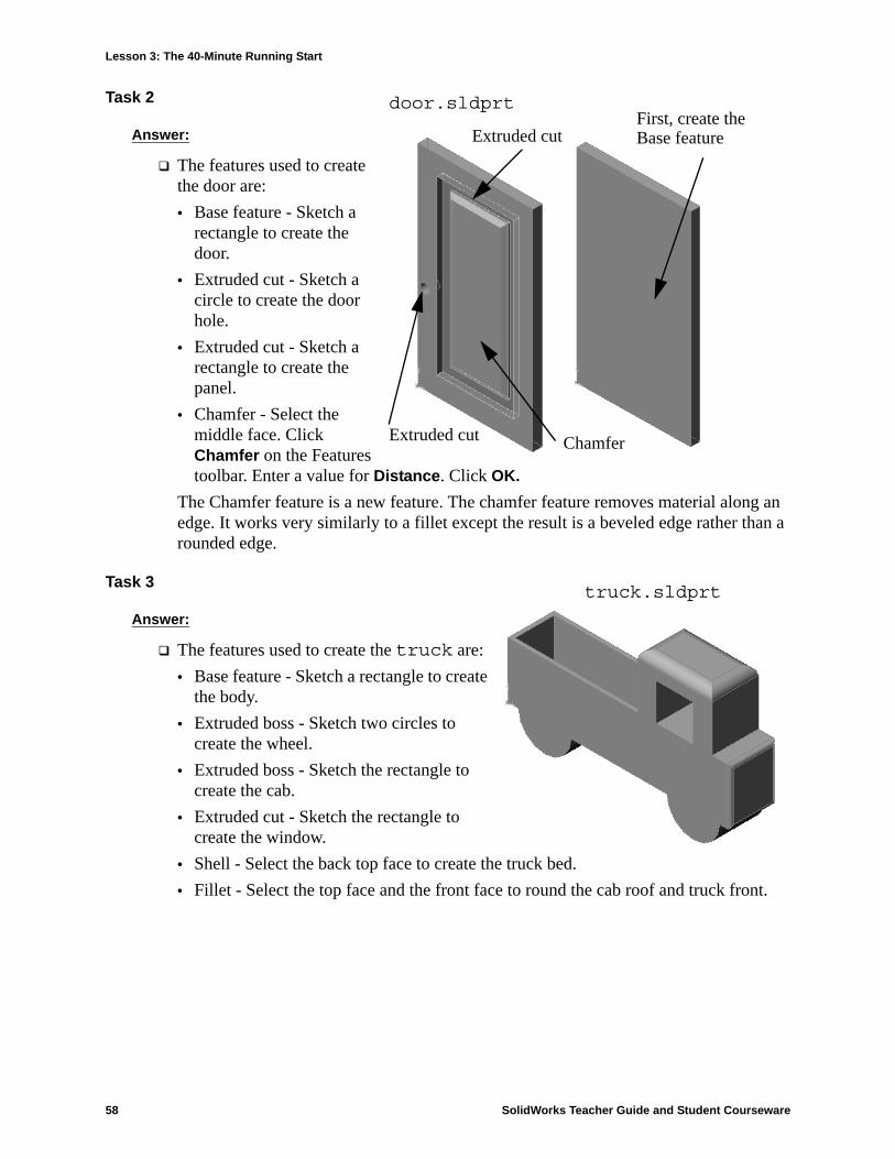
Task 2
Answer:
The features used to create the door are:• Base feature - Sketch a
rectangle to create the door.
• Extruded cut - Sketch a circle to create the door hole.
• Extruded cut - Sketch a rectangle to create the panel.
• Chamfer - Select the middle face. Click Chamfer on the Features toolbar. Enter a value for Distance. Click OK.
The Chamfer feature is a new feature. The chamfer feature removes material along an edge. It works very similarly to a fillet except the result is a beveled edge rather than a rounded edge.
Task 3
Answer:
The features used to create the truck are:• Base feature - Sketch a rectangle to create
the body.• Extruded boss - Sketch two circles to
create the wheel.• Extruded boss - Sketch the rectangle to
create the cab.• Extruded cut - Sketch the rectangle to
create the window.• Shell - Select the back top face to create the truck bed.• Fillet - Select the top face and the front face to round the cab roof and truck front.
First, create the Base feature
door.sldprt
ChamferExtruded cut
Extruded cut
truck.sldprt

Lesson 3: The 40-Minute Running Start REPRODUCIBLE
60 SolidWorks Teacher Guide and Student Courseware
Lesson 3 Quiz
Name: _______________________________Class: _________ Date:_______________
Directions: Answer each question by writing the correct answer or answers in the space provided.
1 How do you begin a new part document? _________________________________________________________________________________________________________
2 How do you open a sketch? ____________________________________________________________________________________________________________________
3 What is the Base feature? ______________________________________________________________________________________________________________________
4 What color is the geometry of a fully defined sketch?________________________________________________________________________________________________
5 How can you change a dimension value?__________________________________________________________________________________________________________
6 What is the difference between an extruded boss feature and an extruded cut feature? _____________________________________________________________________
7 What is a fillet feature?________________________________________________________________________________________________________________________
8 What is a shell feature?________________________________________________________________________________________________________________________
9 Name four types of geometric relations you can add to a sketch? _______________________________________________________________________________________
10 What is a section view? _______________________________________________________________________________________________________________________
11 How do you create multiple views of a part?_______________________________________________________________________________________________________

Lesson 3: The 40-Minute Running Start
SolidWorks Teacher Guide and Student Courseware 61
Lesson Summary
Base Feature is the first feature that is created — the foundation of the part.
The Base Feature is the workpiece to which everything else is attached.
You can create an Extruded Base Feature by selecting a sketch plane and extruding the sketch perpendicular to sketch plane.
Shell Feature creates a hollow block from a solid block.
The views most commonly used to describe a part are:Top ViewFront ViewRight ViewIsometric View

Lesson 3: The 40-Minute Running Start
62 SolidWorks Teacher Guide and Student Courseware
Thumbnail Images of PowerPoint® Slides
The following thumbnail images, arranged left to right, show the PowerPoint slides provided with this lesson.
SolidWorks Teacher Guide Lesson3School’s NameTeacher’s NameDate
Features and Commands
Base Feature
• The first feature that is created.
• The foundation of the part.
• The base feature geometry for the box is an extrusion.
• The extrusion is named Extrude1.
Tip: Keep the base feature simple.
Sketch the 2D profile
Extrude the sketch
To Create an Extruded Base Feature:
1. Select a sketch plane.
2. Sketch a 2D profile.
3. Extrude the sketch perpendicular to sketch plane.
Select the sketch plane
Resulting base feature
Features Used to Build Tutor1
1.Base Extrude 2.Boss Extrude 3.Cut Extrude
4.Fillets 5.Shell
• Extruded Boss Feature
– Adds material to the part.
– Requires a sketch.
• Extruded Cut Feature
– Removes material from the part.
– Requires a sketch.
• Fillet Feature
– Rounds the edges or faces of a part to a specified radius.
• Shell Feature
– Removes material from the selected face.
– Creates a hollow block from a solid block.
– Very useful for thin-walled, plastic parts.
– You are required to specify a wall thickness when using the shell feature.
Lesson 3: The 40-Minute Running Start
SolidWorks Teacher Guide and Student Courseware 63
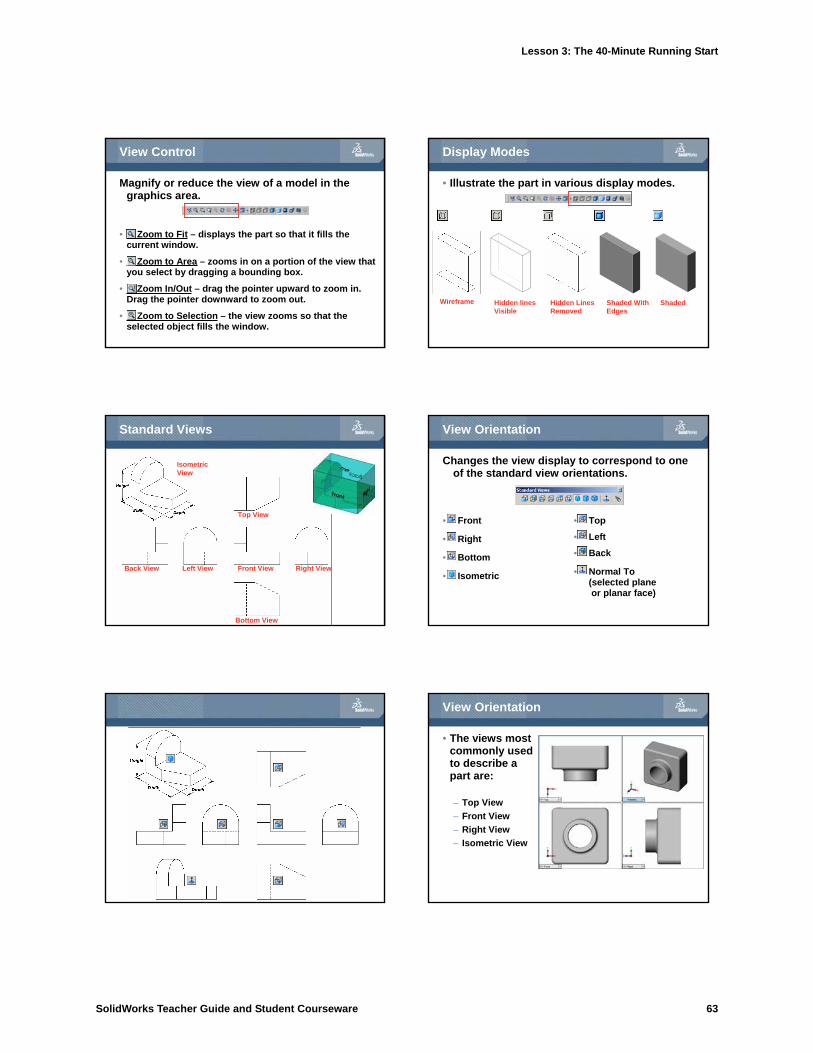
View Control
Magnify or reduce the view of a model in the graphics area.
• Zoom to Fit – displays the part so that it fills the current window.
• Zoom to Area – zooms in on a portion of the view that you select by dragging a bounding box.
• Zoom In/Out – drag the pointer upward to zoom in. Drag the pointer downward to zoom out.
• Zoom to Selection – the view zooms so that the selected object fills the window.
Display Modes
• Illustrate the part in various display modes.
Wireframe Hidden lines
Visible
Hidden Lines
Removed
Shaded With
Edges
Shaded
Standard Views
Isometric
View
Top View
Back View Left View Front View Right View
Bottom View
View Orientation
• Front
• Right
• Bottom
• Isometric
• Top
• Left
• Back
• Normal To(selected planeor planar face)
Changes the view display to correspond to one of the standard view orientations.
View Orientation
• The views most commonly used to describe a part are:
– Top View
– Front View
– Right View
– Isometric View

Lesson 3: The 40-Minute Running Start
64 SolidWorks Teacher Guide and Student Courseware
Default Planes
• Default Planes
– Front, Top, and Right
Correspond to the standard principle drawing views:
– Front = Front or Back view
– Top = Top or Bottom view
– Right = Right or Left view
Isometric View
• Displays the part with height, width, and depth equally foreshortened.
– Pictorial rather than orthographic.
– Shows all three dimensions –height, width, and depth.
– Easier to visualize than orthographic views.
Section View
• Displays the internal structure of a model.
• Requires a section cutting plane.
Section Plane
Mouse over
The Status of a Sketch
• Under defined– Additional dimensions or relations
are required.
– Under defined sketch entities are blue (by default).
• Fully defined– No additional dimensions or relationships
are required.
– Fully defined sketch entities are black (by default).
• Over defined– Contains conflicting dimensions or
relations, or both.
– Over defined sketch entities are red (by default).
Geometric Relations
• Geometric relations are the rules that control the behavior of sketch geometry.
• Geometric relations help capture design intent.
• Example: The sketched circle is concentric with the circular edge of the extruded boss feature.
• In a concentric relation, selected entities have the same center point.
Geometric Relations
• The SolidWorks default name for circular geometry is an Arc#.
• SolidWorks treats circles as 360° arcs.