solo smart charger
TRANSCRIPT
Fast ChargingSolo Smart ChargerInstall Guide
Pod Point Solo Smart Charger PP-D-130012-15 Install Guide S-UK-D-IG

IET code of practice recommends the Solo charger be mounted to a permanent structure at a height of 750mm-1200mm (see Fig. 1). This is to assist those with accessibility requirements accessing the charger and reduce the risk of vehicle impact.
Fig. 1 - Location and dimensions of the Solo Charger.
For Universal Socketed units, consider the addition of the connector of the charging lead in the overall depth from wall (approximately 200mm should be added).
This guide is intended for use by competent electrical installers to explain the basic requirements and options to be considered when installing a Pod Point Solo electric vehicle supply equipment (EVSE).
The Solo is designed for installations inside or outside. The advanced safety systems we have built in ensure its safe usage. This guidance provides information to assist when installing the Solo Smart EVSE. This guide should not be used for any other EVSE as it may not include the same protective systems as the Pod Point Solo Smart.
Universal Socketed Solo
Tethered Solo
Speed category Fast Charging
Charging speed 1.4kW Up to 22kW
Product family Solo
Solo Smart Charger
Important safety information
The Solo Smart Charger is designed and manufactured to be safe provided they are professionally installed, used and maintained in accordance with the manufacturer’s instructions. They should be installed by approved electrical installers in accordance with national and local regulations applicable at the time of installation, e.g. BS7671:2018.
The Solo is designed to be connected to only one dedicated AC supply. The property must comply with minimum BS7671 standards before installation commences.
Isolator switches, RCD or RCBO that switch all live poles (including neutral) must be installed in the circuit feeding an EVSE.
Locations for install
The Solo can be fitted inside or outside. The installer should consult the site owner to establish their preferred installation location. This should take into consideration the cable length (distance to vehicle being charged), risk of vehicle impact and obstruction of access etc.
Note: Maximum rate of charge can vary depending on vehicle requirements and mains supply voltage.
750-1200mm
Diameter360mm
150mm depth
Pod Point Solo Smart Charger PP-D-130012-15 Install Guide S-UK-D-IG
Earthing arrangements
The Solo EVSE includes a safety monitoring system to detect low voltage supplies, failed earths and potential earth-neutral faults. If a fault condition is detected the charge cycle is ended or prevented. The Solo effectively becomes a double insulated (Class II) device and isolates the vehicle from the supply and earth.
This feature removes the requirement for an earth electrode where it may be ineffective or introduce further risk. The Solo Charger (Tethered or Universal Socketed) may be connected directly to a TN-C-S (PME) earthing system without any special arrangements, and the Solo complies with regulation 722.411.4.1 (v) of BS7671.
Read Pod Point’s advice on earthing arrangements via our installation documents page
Or scan the QR code below to get to our install documents page with your smartphone.
Technical details
The Solo is a Class I/II rated device, pollution degree 3 for 230V / 400V AC 50Hz systems and is IP54 and IK10 rated.The Solo is designed to meet the following European standards: BS EN IEC 61851-1:2019 (BS7671 722.511.101), Low Voltage Directive (LVD) 2014/35/EU and electromagnetic compatibility (EMC) Directive 2014/30/EU. Sockets and EV charging connectors comply with IEC 62196-1.
During production each Solo has been functionally tested for safety using BS EN 61010 & BS EN 61557 approved equipment.
Solo Smart Charger
IEC 61851: (6.3.2 Optional functions)
The Universal Socketed Solo includes an electro-mechanical means of locking Type 2 connectors (as per IEC 61851-1, IEC 62196-2 and BS7671). The Solo does not support (State D) ventilation for lead acid battery vehicles.All Solos include dynamic overcurrent protection.
RCD protection:
From January 2019 all Pod Point chargers include 6mA DC vehicle fault protection and only Type A RCD/RCBO’s are required at source. If the Solo was built earlier than January 2019, Type B RCD protection should be fitted. The symbols printed on the RCD in Fig. 2 can be used to identify the type of RCD protection.Care should be taken if using pollution degree 2 devices if located outside.
Fig. 2 RCD Markings
Type A Type B The RCD may include additional markings.
Notes: A vehicle DC leakage fault can “blind” certain type “AC” RCDs.
Surge Protection Devices (SPDs):
See BS7671: section 443 guidance.The Solo includes Type 3 protection against transient over voltages (+/-2kV Line-Earth and +/-1kV Line-Line as a requirement of EN 61000-6-1). The guidance on risk calculation in section 443.5 in most cases is difficult and it may be prudent that Type 2 protection should be installed at the source of supply, especially if life support equipment or business operations could be affected. Type 1 SPD may also be desired in certain higher risk locations.
Pod Point Solo Smart Charger PP-D-130012-15 Install Guide S-UK-D-IG
Notes: EU homologated battery electric vehicles do not have the ability to create AC supply voltage spikes under normal circumstances. SPDs have a finite life expectancy and may require replacement in as little as 1 year. Frequent checks of the SPD’s health is advised.
Isolation and switching for safety and maintenance To ensure that the Solo Charger can be “turned off” and to enhance security and enable maintenance activities, a double-pole isolator suitably rated must be installed within the circuit (2-pole RCBO can provide isolation).
An additional isolator switch may already be provided in a new build, but is optional for existing dwellings (at the customer’s request and cost). The isolator should be mounted at a height of between 500mm and 1500mm above finished floor level to comply with regulations. The switch should be rated greater than 32 amps. Any devices located outside should comply with pollution degree level 3 for safety and reliability. All installations of accessory devices must also comply to current BS7671 regulations.
Transformers
If a galvanically isolated transformer is required, it should be placed upstream of the Solo. The Neutral output feed of the transformer shall be connected to PE (creating a TN-S system) and the PE taken before any RCD or MCB (if 2-pole modules are used). Resistance measured between the EVSE PE and this Earth must be less than 100 ohms (typically less than 0.6 ohms).
Do not connect the output earth+neutral of the transformer to a TN-C-S or TN-S earth.
Upstream transformer RCD protection maybe of Type AC (if fitted). Downstream Type A RCD protection should be fitted to safeguard against a vehicle fault.
Transformers should be rated for 110% duty cycle to allow for BS EN IEC 61851-1:2019 overcurrent requirements. Transformers should be located in a dry and well ventilated area.
Direct connection to three-phase IT systems are prohibited for three-phase EVSE.
Contact Pod Point if an IT network is to be used with a single-phase Pod Point as it will report an earth fault.
Installation procedure
Prior to any installation work beginning (drilling or fitting of conduit and cables etc.), allow the customer to visualise where the EVSE will be installed. Consider cable trip hazards and access routes. Once the customer has confirmed the location meets their expectations, the location may be marked up and installation can commence.
Non-permanent structures must not be used to fit the EVSE to, e.g. fences and trees.
The installer should confirm the wall that the EVSE is intended to be fixed to is structurally appropriate for the mounting of the Solo. The installer should identify the construction of the wall, and identify the correct and appropriate fixings to use.
• The Solo charger must be securely attached to the wall or permanent structure where it is intended to be operated from.
• To maintain IK10, at least 80mm long screws must be used for brick or concrete, and it is recommended penny washers be included.
Once the location and height of the Solo charger has been decided, the installer can begin marking the wall with indicator points to locate the Solo. Use the back of the box insert as the drilling template for the three mounting holes (Fig. 3).
Solo Smart Charger
Pod Point Solo Smart Charger PP-D-130012-15 Install Guide S-UK-D-IG
• Notes: If any groundworks are required (cable trenching or earth electrode fitment) it is advisable to check if underground services could be present before commencement. Plans for undergrounds services maybe available at: linesearchbeforeudig.co.uk
• Before drilling commences ensure that the installation wall has been checked for electric cabling or pipework with a suitable detector.
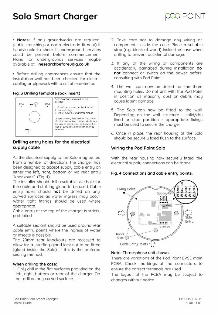
Fig. 3 Drilling template (box insert)
Drilling entry holes for the electrical supply cable As the electrical supply to the Solo may be fed from a number of directions, the charger has been designed to accept supply cable entry on either the left, right, bottom or via rear entry “knockouts” (Fig. 4). The installer should drill a suitable size hole for the cable and stuffing gland to be used. Cable entry holes should not be drilled on any curved surfaces as water ingress may occur. Water tight fittings should be used where appropriate. Cable entry at the top of the charger is strictly prohibited.
A suitable sealant should be used around rear cable entry points where the ingress of water or insects is possible. The 20mm rear knockouts are recessed to allow for a stuffing gland lock nut to be fitted (gland inside the Solo), if this is the prefered sealing method.
When drilling the case:1. Only drill in the flat surfaces provided on the
left, right, bottom or rear of the charger. Do not drill on any curved surface.
2. Take care not to damage any wiring or components inside the case. Place a suitable stop (e.g. block of wood) inside the case when drilling to prevent accidental damage.
3. If any of the wiring or components are accidentally damaged during installation do not connect or switch on the power before consulting with Pod Point.
4. The wall can now be drilled for the three mounting holes. Do not drill with the Pod Point in position as masonry dust or debris may cause latent damage.
5. The Solo can now be fitted to the wall. Depending on the wall structure - solid/dry lined or stud partition - appropriate fixings must be used to secure the charger.
6. Once in place, the rear housing of the Solo should be securely fixed flush to the surface.
Wiring the Pod Point Solo
With the rear housing now securely fitted, the electrical supply connections can be made.
Fig. 4 Connections and cable entry points.
Note: Three-phase unit shown.There are variations of the Pod Point EVSE main PCBA. Check markings at the connectors to ensure the correct terminals are used. The layout of the PCBA may be subject to changes without notice.
Solo Smart Charger
Pod Point Solo Smart Charger PP-D-130012-15 Install Guide S-UK-D-IG
Wiring of the Solo Charger (continued)
When the Solo has been fitted and supply cables have been fixed and fitted, wiring may commence
• Allow enough cable length to ensure cables and terminals are not strained. To avoid cable interference do not route cables over the PCBA on Socketed Solos as this will prevent the cover with socket fitting correctly.
• When cutting SWA cables, allow at least 10mm of inner insulator to enter the Solo housing to avoid cores “chafing” with the gland or SWA.
• Fig. 4 illustrates the connection terminals for the electrical supply cables. Ensure that incoming cables are connected to the appropriate terminal as follows: Earth: Green/Yellow
Neutral: Blue
Live 1: Brown
Live 2: Black (three-phase units only)
Live 3: Grey (three-phase units only)
All cables to be connected into the supply terminals should have their insulation stripped back 12~15mm to provide good contact to the screw terminal jaws. Take care to avoid clamping the cable insulation.Torque settings for the incoming supply connections is 1.5~2.0Nm. Pull tests shall be performed at the terminals to confirm the cables are secured.
Where domestic load management is fitted, use the appropriate cables and wire into GND and EXTC terminals. These connections require no more than 0.5Nm of torque. Overtightening these terminals can sever the cables and damage the terminals. See later section for wiring the energy monitoring transformer for load curtailment.
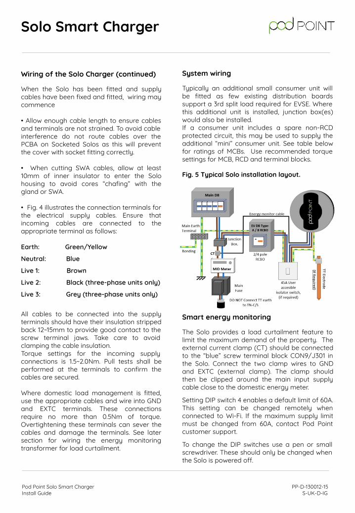
System wiring
Typically an additional small consumer unit will be fitted as few existing distribution boards support a 3rd split load required for EVSE. Where this additional unit is installed, junction box(es) would also be installed. If a consumer unit includes a spare non-RCD protected circuit, this may be used to supply the additional “mini” consumer unit. See table below for ratings of MCBs. Use recommended torque settings for MCB, RCD and terminal blocks.
Fig. 5 Typical Solo installation layout.
Smart energy monitoring
The Solo provides a load curtailment feature to limit the maximum demand of the property. The external current clamp (CT) should be connected to the “blue” screw terminal block CON9/J301 in the Solo. Connect the two clamp wires to GND and EXTC (external clamp). The clamp should then be clipped around the main input supply cable close to the domestic energy meter.
Setting DIP switch 4 enables a default limit of 60A. This setting can be changed remotely when connected to Wi-Fi. If the maximum supply limit must be changed from 60A, contact Pod Point customer support.
To change the DIP switches use a pen or small screwdriver. These should only be changed when the Solo is powered off.
Solo Smart Charger
Pod Point Solo Smart Charger PP-D-130012-15 Install Guide S-UK-D-IG
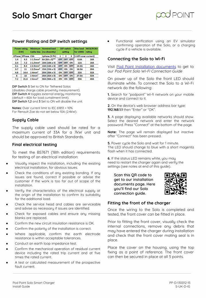
Power Rating and DIP switch settings
DIP Switch 5 Set to ON for Tethered Solos (disables charge cable proximity measurement).DIP Switch 4 toggles external energy monitoring (default = 60A for load curtailment limit).DIP Switch 1,2 and 3 Set to ON will disable the unit.
Notes: Over current limit to IEC 61851 = 10%For Renault Zoe do not set below 10A (2.4kW).
Supply Cable
The supply cable used should be rated for a maximum current of 33A for a 7kW unit and should be approved to British Standards.
Final electrical testing
To meet the BS7671 (18th edition) requirements for testing of an electrical installation:
Connecting the Solo to Wi-Fi
Visit Pod Point Installation documents to get to our Pod Point Solo Wi-Fi Connection Guide
On power up of the Solo the front LED should illuminate white. To connect the Solo to a Wi-Fi network do the following:
1. Search for “podpoint” Wi-fi network on your mobile device and connect to it.
2. On the device’s web browser address bar type: 192.168.1.1 then “Enter” or “OK”.
3. A page displaying available networks should show. Select the desired network and enter the network password. Press “Connect” at the bottom of the page.
Note: The page will remain displayed but inactive after “Connect” has been pressed.
5. Power cycle the Solo and wait for 1 minute.The LED should change to blue with a short magenta flash when it has connected.
6. If the status LED remains white, you mayneed to restart the charger again and verify thesettings (see notes at end of this guide).
Fitting the front of the charger
Once the wiring to the Solo is completed and tested, the front cover can be fitted in place.
Prior to fitting the front cover, visually check the internal connections, remove any debris that may have entered the charger during installation and check that the front cover mating seal is in place.
Place the cover on the housing, using the top fixing as a point of reference. The front cover can then be secured in place at all 5 points.
Solo Smart Charger
Scan this QR code to get to our installation documents page. Here you’ll find our Solo connection guide.
Pod Point Solo Smart Charger PP-D-130012-15 Install Guide S-UK-D-IG
● Visually inspect the installation, including the existing electrical installation, for obvious issues.
● Check the conditions of any existing bonding. If any issues are found, correct if possible or advise the customer if the work is too far out of scope of the installation.
● Verify the characteristics of the electrical supply at the origin of the installation to confirm its suitability for the additional load.
● Check the service head and cables are serviceable and advise as necessary if issues are identified.
● Check for exposed cables and ensure any missing blanks are replaced.
● Confirm the new circuit insulation resistance is OK.● Confirm the polarity of the installation is correct.● Where applicable, confirm the earth electrode
resistance is within acceptable tolerances.● Conduct an earth loop impedance test.● Confirm the mechanical operation of residual current
device including the rated trip current and at five times the rated current.
● A test or calculated measurement of the prospective fault current.
● Functional verification using an EV simulator confirming operation of the Solo, or a charging cycle if a vehicle is available.
MID approved energy monitoring
The Solo does not include MID approvals for energy monitoring (it does not have a display). A MID approved meter can be connected to the Solo’s “MID” input terminals located at the lower left-hand corner of the PCBA. MID meters should be “pulsed” with an output of 2000 imp/Kw/h. Charge energy data by default uses the Solo’s onboard measuring system. In most circumstances this energy reading will report lower than an upstream energy meter (due to cable losses). Onboard energy measurements are typically within 2% accuracy.
RCD protection:
Upstream RCD / RCBOs provide protection for the entire system including supply cable. As 2-pole isolation is a minimum legal requirement for EVSE, this module also provides this functionality.
Cable and adaptors warning
IEC 61851-1 dictates that in-cable adaptors must be approved by the vehicle or the charge point manufacturer. In the interests of safety Pod Point do not approve the use of any in-cable adaptors for customer use as they can, and do, override safety features.
Charging adaptors that change the operational state of the EVSE are not allowed under terms of IEC 61851-1. Adaptors or smart cables (commonly used for energy management) are not approved as electrical safety may be compromised due to these units taking control of the chargepoint, potentially bypassing fundamental safety systems. Diagnostic information provided by the Solo can identify if these adaptors are used.
It is prudent to visually check both plugs and sockets for damage or debris before every use. Ensure all connectors can be fully plugged into the vehicle and chargepoint before use. Vehicle, cable or chargepoint manufacturers may not cover damaged cables under terms of warranty.
Accessories, features and helpful hints
The Solo family of EVSE supports optional features that may not be used in a domestic environment. This section provides more information on these features.
Remote diagnostics
When connected to the internet via Wi-Fi the Solo will provide information on supply voltage(s), the status of the incoming earth, charging current, temperature, rating of connected cable, etc. This data is primarily used for internal diagnostic purposes but is also used for energy usage displayed in the Pod Point App. In exceptional circumstances Pod Point may contact the site/charger owner if an abnormality is detected.
Wi-Fi operation To minimise standby energy consumption the Solo Wi-Fi module will enter Sleep Mode when not required. Only small packets of diagnostic data are sent every few minutes.
The Solo is not able to connect to public networks that require “guest” authentication (captive portals). In such circumstances an IT engineer may need to grant access to the unit using the MAC address or by adding a “limited” SSID for the Solo (a “guest” network with only access to the internet) if supported by the router.
There are known routers that are troublesome with allowing connection of some devices. Adding the Solo’s MAC address to these routers’ “access control list” usually works around this issue but does require some IT skills to set up.
Wi-Fi must be able to support 2.4Ghz operation. AC only enabled routers will not work.
Solo Smart Charger
Pod Point Solo Smart Charger PP-D-130012-15 Install Guide S-UK-D-IG
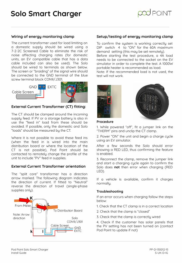
Wiring of energy monitoring clampThe current transformer used for load limiting on a domestic supply should be wired using a 7-2-2C Screened Cable to eliminate the risk of noise affecting charging rates (for domestic units, an EV compatible cable that has a data cable included can also be used). The Solo should be wired to terminals as shown below. The screen or “braiding” of the signal wire should be connected to the GND terminal of the blue screw terminal block CON9/J301.
External Current Transformer (CT) fitting:
The CT should be clamped around the incoming supply feed. If PV or a storage battery is also in use the “feed in” load from these should be avoided. If possible, only the domestic and Solo “loads” should be measured by the CT.
Where it is not possible to avoid these feed ins (when the feed in is wired into the main distribution board or where the location of the CT is not possible), Pod Point should be contacted to remotely change the profile of the unit to include “PV” feed in supplies.
External Current Transformer orientation
The “split core” transformer has a direction arrow marked. The following diagram indicates the direction of current. If fitted to “Neutral” reverse the direction of travel (single-phase supplies only).
Solo Smart Charger
Setup/testing of energy monitoring clamp
To confirm the system is working correctly set DIP switch 4 to “ON” for the 60A maximum demand setting (this may be set remotely).Before starting the test procedure, a 4A load needs to be connected to the socket on the EV simulator in order to complete the test. A 1000W portable heater is recommended as load.Note: If the recommended load is not used, the test will not work.
Procedure1. While powered “off”, fit a jumper link on the “THERM” pins and unclip the CT clamp.2. Power “ON” the unit and begin a charge cycle using an EV simulator.After a few seconds the Solo should error showing a RED LED, thus confirming the feature is enabled.3. Reconnect the clamp, remove the jumper link and start a charging cycle again to confirm the Solo does not then error when charging (RED LED).
If a vehicle is available, confirm it charges normally.
TroubleshootingIf an error occurs when charging follow the steps below:1. Check that the CT clamp is in a correct location2. Check that the clamp is “closed”3. Check that the clamp is correctly wired4. Check if the customer has solar panels that the PV setting has not been turned on (contact Pod Point to update if not)
Pod Point Solo Smart Charger PP-D-130012-15 Install Guide S-UK-D-IG

5. Unclip the CT, so as not to measure current and proceed to a resistance check at GND/EXTC terminals to confirm the correct wiring:
- 100 ohms indicates an open circuit in the cable or clamp.
- Lower than 10 ohms indicates a short circuit in the cable.
- Approximately 70 ohms indicates cable and clamp are OK.
If an error still occurs, it’s likely to be a faulty clamp (the ferrite cores can be broken if the clamp is dropped or mishandled).
If a clamp “buzzes” check it is clipped “shut” and/or check the resistance is correct (~70 ohms). CTs with no burden load can buzz.
Notes:
The measured charging current of the Solo should equal the same or less than the external clamp measures.If enabled remotely the DIP switch 4 may have the reverse effect.
Key lock
Solos can include a key lock feature to disable use of the chargepoint where theft of electricity is a concern. The key lock input requires “volt free” isolated switching contacts. When the contacts are closed the Solo enters a “Pause” state and the LED will flash yellow after 5 seconds.
The charge cable will not lock into the Solo if the key lock is turned off upon insertion of the charging cable.
Theft of the Pod Point SoloEvery Pod Point charger uses a unique MAC address to identify itself which is programmed into the silicon and cannot be changed. If a stolen Solo is reported and its connection to the Pod Point Network is attempted, it can be placed permanently out of service.
Solo Smart Charger
Troubleshooting Wi-Fi connection problems
Sometimes Wi-Fi routers block the connection of devices for various reasons. These may be related to the total number of connected devices, bugs in the router's ARP table, password errors and other system settings.
If it is confirmed the correct network and password have been entered (the device used for setting up may “capitalise” the 1st password character etc.) and the Solo fails to connect after it has been restarted, a restart of the Wi-Fi router may fix the issue. The router should refresh the ARP table if conflicts existed.
Check to make sure the default router password has not been changed.
Check the password is no longer that 15 characters.
Solos support 802.11 b, g and n Wi-Fi networks. AC is not supported. Ensure 2.4Ghz Wi-Fi is enabled on the router.
Check the security settings on the router have not been changed. Pod Point chargers use WPA2 by default.
Check the router's settings have not been modified to limit the number of users it will allow to connect.
Some low cost Wi-Fi routers have a maximum limit of connected devices they can support. If possible remove a device from the network and retry. If this solves the issue it is recommended the user upgrades their Wi-Fi router.
If a managed IT network is in use, the addition of the Solo using the MAC address may be the only option. The MAC address can be provided by Pod Point from the PSL number of the unit, which is then included in the router’s “allowlist”.
Some Technicolour routers will only allow connection after the Solo's MAC address is added to the allowlist. After adding this the Solo can be added in the usual way.
Solos cannot connect to networks that require an email address or where T&Cs need to be agreed.
Pod Point Solo Smart Charger PP-D-130012-15 Install Guide S-UK-D-IG
Wi-Fi security concerns
If a “guest” network can be set up on the router (most ISP provided routers do not have this feature), limiting connections to one device with access limited only to the internet gives security conscious users some peace of mind.
Setting up an allowlist on a router adds an additional layer of security from attackers. This requires some level of IT knowledge to add the various MAC addresses. It also makes connection of any future devices more difficult. Using the Wi-Fi router's SSID and password will not automatically allow connection.Viewing a router’s list of connected devices should reveal the Solo as “Mysimplelink” followed by a number (MAC address). This MAC address may be used for the setting up of an allowlist.
WPS and PIN number access are regarded as insecure and should be disabled in the router’s settings if not used.
Commissioning of the Solo
It is important that all Pod Point EVSE are commissioned once they have been installed. Failure to do so will mean the EVSE are not covered by warranty, and the end user will not be able to access the charging point via the Pod Point App.
Commissioning of Commercial Solo chargers:
To commission a commercial Pod Point charger you will need to complete the commission form at:pod-point.com/3rd-party-commissioning
Commissioning of Domestic Solo chargers:
To commission a domestic Pod Point charger please complete the commissioning form at:
podpoint.force.com/commissioning/s/login/
Solo Smart Charger
For more information about domestic Pod Point commissioning:
pod-point.com/products/installer/domestic-install-training
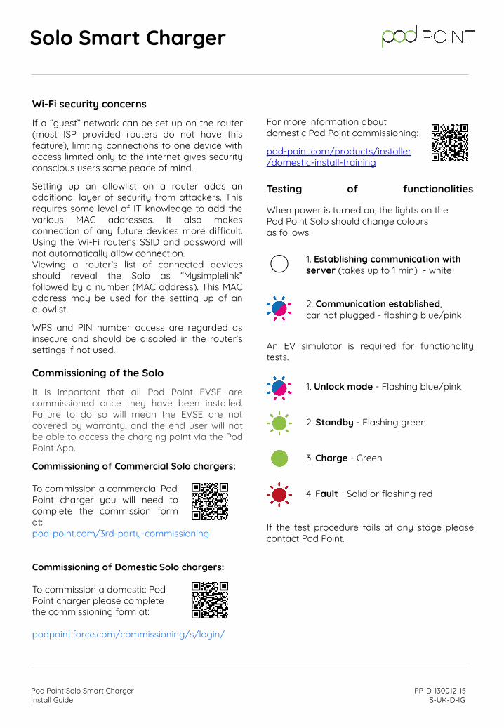
Testing of functionalities
When power is turned on, the lights on the Pod Point Solo should change colours as follows:
1. Establishing communication with server (takes up to 1 min) - white
2. Communication established, car not plugged - flashing blue/pink
An EV simulator is required for functionality tests.
1. Unlock mode - Flashing blue/pink
2. Standby - Flashing green
3. Charge - Green
4. Fault - Solid or flashing red
If the test procedure fails at any stage please contact Pod Point.
Pod Point Solo Smart Charger PP-D-130012-15 Install Guide S-UK-D-IG