solstart - démarreurs progressifs · when the line contactor is operated by a maintained contact,...
TRANSCRIPT
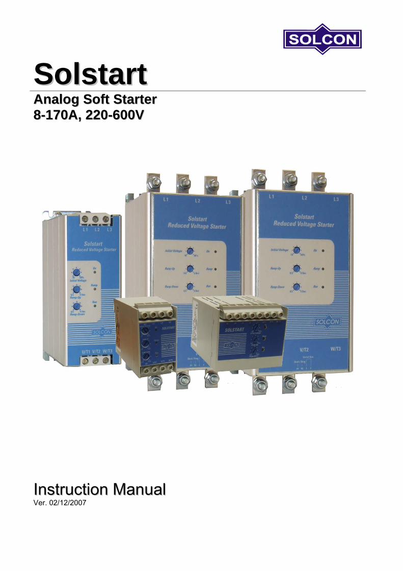
SSoollssttaarrtt
AAnnaalloogg SSoofftt SSttaarrtteerr 88--117700AA,, 222200--660000VV
IInnssttrruuccttiioonn MMaannuuaall Ver. 02/12/2007
2 • Table of Content
________________________________________________________________________________________________
SOLSTART Instruction Manual 1. TABLE OF CONTENT
1. Table of Content .......................................................................................................................2
2. Safety & Warnings....................................................................................................................3 2.1 Safety..........................................................................................................................................3 2.2 Attention......................................................................................................................................3 2.3 Warnings.....................................................................................................................................3
3. Technical Data ..........................................................................................................................4 3.1 Introduction .................................................................................................................................4 3.2 Rating and frames sizes .............................................................................................................4 3.3 Starter Selection .........................................................................................................................4 3.4 Mains and control description .....................................................................................................5
3.4.1 Mains Voltage (line to line) (Terminals/bars L1, L2, L3)..................................................5 3.4.2 Start/Stop (Terminals A1,A2) ..........................................................................................5 3.4.3 End Of Acceleration (terminals 3, 4) Solstart 31A and up...............................................5
3.5 Built-in Bypass ............................................................................................................................5 3.6 Starter selection tables for various voltage ratings. ....................................................................6
3.6.1 Ordering Information .......................................................................................................7 4. Recommended Wiring Schemes .............................................................................................8
4.1 Typical wiring diagram ................................................................................................................8 4.2 Wiring Notes ...............................................................................................................................8
4.2.1 Short Circuit Protection ...................................................................................................9 4.2.2 Transient Protection ........................................................................................................9
5. Dimensions .............................................................................................................................10
6. Installation...............................................................................................................................12 6.1 Prior to Installation ....................................................................................................................12 6.2 Mounting ...................................................................................................................................12 6.3 Temperature range & heat dissipation......................................................................................12
6.3.1 Calculating the enclosure size, for non-ventilated metallic enclosure ...........................12 6.3.2 Additional Ventilation.....................................................................................................13
7. Front Panel ..............................................................................................................................14 7.1 Potentiometers settings ............................................................................................................14 7.2 Indication LEDs.........................................................................................................................15
8. Starting Procedure .................................................................................................................16 8.1 Standard starting procedure .....................................................................................................17 8.2 Examples of starting curves......................................................................................................18 8.3 Warranty Claim and Fault Inquiry .............................................................................................19
9. Technical Specifications........................................................................................................20

3 • Safety & Warnings
2. SAFETY & WARNINGS 2.1 Safety
1 Read this manual carefully before operating the equipment and follow its instructions.
2 Installation, operation and maintenance should be in strict accordance with this manual, national codes and good practice.
3 Installation or operation not performed in strict accordance with these instructions will void manufacturer’s warranty.
4 Disconnect all power inputs before servicing the soft-starter and/or the motor.
5 After installation, check and verify that no parts (bolts, washers, etc.) have fallen into the starter.
6 During shipping, the soft-starter might have been roughly handled, therefore, it is recommended to initialize the soft-starter by connecting supply voltage prior to operating the soft-starter with a motor
2.2 Attention
1 This product was designed for compliance with IEC 947-4-2 for class A equipment.
2 Use of the product in domestic environments may cause radio interference, in which case, the user may be required to employ additional mitigation methods.
3
Utilization category is AC-53a or AC53b, Form 1. For further information, see Technical Specification
2.3 Warnings
1 Internal components and PCBs are at mains potential when the SOLSTART is connected to mains. This voltage is extremely dangerous and will cause death or severe injury if contacted.
2
When SOLSTART is connected to mains, even if start command has not been issued and motor is stopped, full voltage appears on starter’s output and motor’s terminals. Therefore, for isolation purposes it is required to connect an isolation device upstream to the SOLSTART.
3 The starter must be grounded (models Solstart 31A and up) to ensure correct operation, safety and to prevent damage.
4 Check that Power Factor capacitors are not connected to the output side of the soft starter.
5 Do not interchange line and load connections
The company reserves the right to make any improvements or modifications to its products without prior notice.
________________________________________________________________________________________________

4 • Technical Data
3. TECHNICAL DATA 3.1 Introduction The SOLSTART electronic soft starter incorporates two sets of thyristors (Two phase control) to start a three-phase squirrel cage induction motor and an internal bypass. By supplying a slowly increasing voltage, it provides soft start and smooth stepless acceleration, while drawing the minimum current necessary to start the motor. A Soft Stop feature can be enabled when the Ramp-Down potentiometer is adjusted. When used, upon stop signal, motor's voltage is slowly reduced to zero. No control voltage is required to operate the SOLSTART. 3.2 Rating and frames sizes SOLSTART
model FLC [A]
Dimensions WxHxD [mm]
Weight [kg]
EOA
Rel
ay
Alu
min
ium
ca
se
Din
rail
mou
ntin
g
SOLSTART 8 8 45x75x110 0.42 (-) (-) SOLSTART 17 17 90x75x105 0.55 (-) (-) SOLSTART 22 22 90x75x105 0.55 (-) (-) SOLSTART 31 31 65x190x114 1.3 O SOLSTART 44 44 65x190x114 1.3 O SOLSTART 58 58 65x190x114 1.3 O SOLSTART 72 72 120x265x121 C (-) SOLSTART 85 85 120x265x121 C (-)
SOLSTART 105 105 120x265x121 C (-) SOLSTART 145 145 129x275x182 C (-) SOLSTART 170 170 129x275x182 C (-)
Notes:
• – Standard • O – Option • C – Consult factory • (-) – Not available • Refer to section 5 on page 10 for detailed dimensions.
3.3 Starter Selection Select the starter according to motor's Full Load Ampere (FLA) - as indicated on its nameplate (even if the motor will not be fully loaded). The SOLSTART is designed to operate under the following maximum conditions:
Ambient Temperature
[0C]
Starting Current [A]
Acceleration Time [sec]
40 350%xIn 5 Max. starts per Hour: four (4) starts per hour at maximum ratings and up to 10 starts per hour at light load applications (consult factory). Note: For very frequent starts (inching applications) the inching current should be considered as the Full Load Current (FLC) (consult factory).
________________________________________________________________________________________________

5 • Technical Data
3.4 Mains and control description 3.4.1 Mains Voltage (line to line) (Terminals/bars L1, L2, L3) Five mains voltage levels are available: 230V, 400V, 440, 480V, 600V. Note: 230 220 - 240 Vac +10% -15% 400 380 - 415 Vac +10% -15% 440 440 Vac +10% -15% 480 460 - 500 Vac +10% -15% 600 575 - 600 Vac +10% -15% 3.4.2 Start/Stop (Terminals A1,A2) Start/Stop command is initiated by closing/opening a voltage free contact (Dry contact)
Close: Start command.
Open: Stop command.
Never apply voltage to terminals A1, A2.
Start/Stop with a maintained contact!
WARNING!
When the line contactor is operated by a maintained contact, in case of Mains failure, the motor will be automatically restarted upon voltage restoration!
3.4.3 End Of Acceleration (terminals 3, 4) Solstart 31A and up Voltage free, N.O., 5A / 250VAC, Solstart 31-58A Voltage free, N.O., 8A / 250VAC, Solstart 72-170A The contact closes after the time adjusted on the "Ramp-Up" potentiometer. The contact returns to its original position on stop signal or upon voltage outage. This contact can be used for: • Activating a valve after a compressor has reached full speed. • Activating a valve after a pump has reached full speed. • Loading a conveyor after the motor has reached full speed. 3.5 Built-in Bypass The SOLSTART incorporates two internal bypass relays allowing current flow through the thyristors only during starting process. At the end of the starting process, the built-in relays bypass the thyristors and carry the current to the motor. When Ramp-Down potentiometer is set to allow soft-Stop process, upon stop command, the bypass relays will open immediately and the current will flow through the thyristors. The voltage will then be reduced slowly and smoothly to zero.
________________________________________________________________________________________________

6 • Technical Data
3.6 Starter selection tables for various voltage ratings.
1 The starter selection table below concern standard, 1500r.p.m. 50Hz, three-phase motors.
2 These values are given for guidance and may vary according to motor manufacturer and depending on the number of poles.
3 It is the user’s responsibility to make sure that motor’s FLA will never exceed Starter’s FLC.
Starter model Starter
FLC [A]
Motor kW @230V
[kW]
Motor kW @400V
[kW]
Motor kW @480V
[kW]
Motor kW @600V
[kW]
SOLSTART 8 8 1.5 3 4 5.5 SOLSTART 17 17 4 8 9 12.5 SOLSTART 22 22 5.5 11 12.5 15 SOLSTART 31 31 8 15 18.5 25 SOLSTART 44 44 12.5 22 25 30 SOLSTART 58 58 15 25 37 45 SOLSTART 72 72 20 37 45 59 SOLSTART 85 85 25 45 55 59
SOLSTART 105 105 30 55 59 80 SOLSTART 145 145 40 75 90 110 SOLSTART 170 170 51 90 110 140
________________________________________________________________________________________________
7 • Technical Data
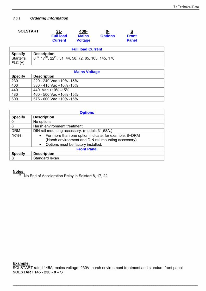
3.6.1 Ordering Information
SOLSTART 31- 400- 0- S
Full load Current
Mains Voltage
Options Front Panel
Full load Current
Specify Description Starter’s FLC [A]
8(1), 17(1), 22(1), 31, 44, 58, 72, 85, 105, 145, 170
Mains Voltage
Specify Description 230 220 - 240 Vac +10% -15% 400 380 - 415 Vac +10% -15% 440 440 Vac +10% -15% 480 460 - 500 Vac +10% -15% 600 575 - 600 Vac +10% -15%
Options Specify Description 0 No options 8 Harsh environment treatment DRM DIN rail mounting accessory. (models 31-58A.) Notes: • For more than one option indicate, for example: 8+DRM
(Harsh environment and DIN rail mounting accessory) • Options must be factory installed.
Front Panel Specify Description S Standard lexan Notes:
(1) No End of Acceleration Relay in Solstart 8, 17, 22 Example: SOLSTART rated 145A, mains voltage- 230V, harsh environment treatment and standard front panel: SOLSTART 145 - 230 - 8 – S
________________________________________________________________________________________________

8 • Recommended Wiring Schemes
4. RECOMMENDED WIRING SCHEMES 4.1 Typical wiring diagram
Notes:
(1) - Use fuses for type 2 coordination. Refer to section 4.2.1 on page 9(2) – Use a maintained contact to start the motor. Open the contact to soft stop/stop the motor. Contact must be closed one second after voltage at L1, L2, L3 is stable.
Never apply voltage to terminals A1 & A2.
(3) – End Of Acceleration contact is in SOLSTART 31A and up. (4) – Ground connection is in SOLSTART 31A and up.
4.2 Wiring Notes
When mains voltage is connected to the SOLSTART, full voltage appear on starter load terminals. Therefore, for isolation purposes, it is necessary to connect an isolating device before the starter. Power factor correction capacitors must not be installed on starters load side. When required, install capacitors on starter’s line side.
WARNINGS!
Never connect the SOLSTART “Inside Delta”!
________________________________________________________________________________________________
9 • Recommended Wiring Schemes
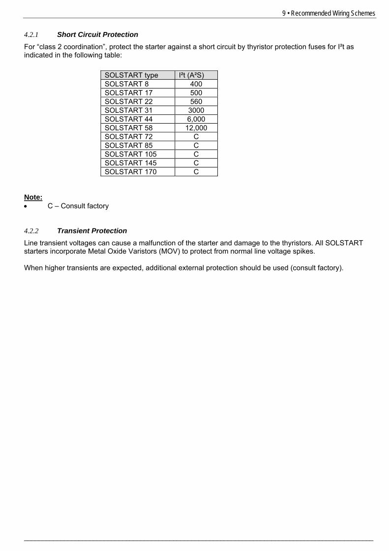
4.2.1 Short Circuit Protection For “class 2 coordination”, protect the starter against a short circuit by thyristor protection fuses for I²t as indicated in the following table:
SOLSTART type I²t (A²S) SOLSTART 8 400 SOLSTART 17 500 SOLSTART 22 560 SOLSTART 31 3000 SOLSTART 44 6,000 SOLSTART 58 12,000 SOLSTART 72 C SOLSTART 85 C SOLSTART 105 C SOLSTART 145 C SOLSTART 170 C
Note: • C – Consult factory 4.2.2 Transient Protection Line transient voltages can cause a malfunction of the starter and damage to the thyristors. All SOLSTART starters incorporate Metal Oxide Varistors (MOV) to protect from normal line voltage spikes. When higher transients are expected, additional external protection should be used (consult factory).
________________________________________________________________________________________________

10 • Dimensions
5. DIMENSIONS
SOLSTART 8 Note: Mains voltage terminals: 4mm2
SOLSTART 17, 22 Note: Mains voltage terminals: 4mm2
SOLSTART 31, 44, 58
________________________________________________________________________________________________

11 • Dimensions
SOLSTART 72, 85, 105
SOLSTART 145, 170
________________________________________________________________________________________________

12 •
6. INSTALLATION
Do not interchange line and load connections WARNING! Do not connect the SOLSTART “Inside Delta”
6.1 Prior to Installation Check that Motor’s Full Load Ampere (FLA) is lower than, or equal, to the starter’s Full Load Current (FLC) and that Mains and Control voltages are as indicated on the starter’s side label.
Make sure Starter’s FLC≥ Motor FLA! Make sure Mains voltage is right! Make sure control is by voltage free contact!
SOLSTART label - example 6.2 Mounting The starter must be mounted vertically. Allow sufficient space (at least 100mm) above and below the starter for suitable airflow. It is recommended to mount the starter directly on the rear metal plate for better heat dissipation. Do not mount the starter near heat sources. Surrounding air temperature in the cabinet should not exceed 40ºC Protect the starter from dust and corrosive atmospheres. Note: For harsh environments (sewage treatment plants, etc.), it is recommended to order the starter with printed circuit board coating. Refer to section 3.6.1 on page 7 for ordering information. 6.3 Temperature range & heat dissipation The starter is rated to operate over a temperature range of -10ºC (14ºF) to + 40ºC (104ºF). Relative non-condensed humidity inside the enclosure should not exceed 95%. ATTENTION! Operating at surrounding air temp. (Inside the cabinet) higher than 40ºC may
cause damage to the starter. Starter’s heat dissipation while motor is running and the internal bypass relays are closed is typically less than 0.3 x In (in watts). During soft start and soft stop, heating is approximately two times the actual starting current (In watts). Example: For a 17A motor, heat dissipation is less than 5.1 watts while running. Important note: If motor is frequently started, cabinet should be designed for the higher heat dissipation. Internal enclosure heating can be reduced through the use of additional ventilation. 6.3.1 Calculating the enclosure size, for non-ventilated metallic enclosure Area (m2) = 0.12 x Total heat dissipation [Watts]
60 – External ambient temp. [ºC] Where: Area [m2]] - Surface area that can dissipate heat (front, sides, top).
Total heat dissipation [Watt] – The total heat dissipation of the starter and other control devices in the enclosure. If starter is frequently started, average power should be used.
________________________________________________________________________________________________

13 • Installation
6.3.2 Additional Ventilation Use the following arrangement for forced ventilation of the SOLSTART’s enclosure:
Solstart
General purpose enclosure with filter on the air inlet and Fan on air outlet.
________________________________________________________________________________________________
14 • Front Panel
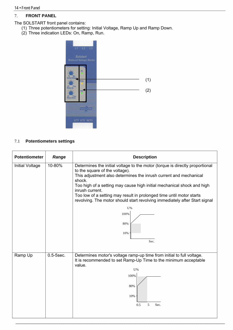
7. FRONT PANEL The SOLSTART front panel contains:
(1) Three potentiometers for setting: Initial Voltage, Ramp Up and Ramp Down. (2) Three indication LEDs: On, Ramp, Run.
7.1 Potentiometers settings
Potentiometer Range Description
Initial Voltage 10-80% Determines the initial voltage to the motor (torque is directly proportional to the square of the voltage). This adjustment also determines the inrush current and mechanical shock. Too high of a setting may cause high initial mechanical shock and high inrush current. Too low of a setting may result in prolonged time until motor starts revolving. The motor should start revolving immediately after Start signal
Ramp Up 0.5-5sec. Determines motor's voltage ramp-up time from initial to full voltage. It is recommended to set Ramp-Up Time to the minimum acceptable value.
U%
10%
80%
100%
5 Sec.0.5
U%
10%
80%
100%
Sec.
(2)
(1)
________________________________________________________________________________________________
15 • Front Panel
Potentiometer Range Description
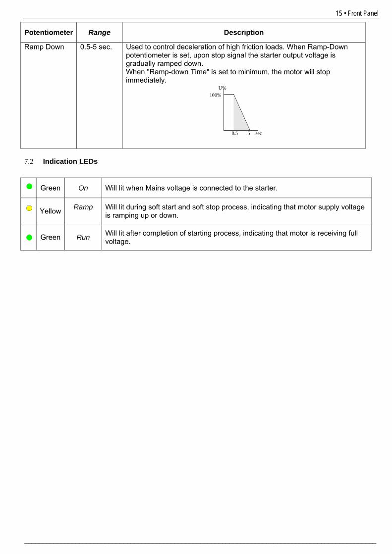
Ramp Down 0.5-5 sec. Used to control deceleration of high friction loads. When Ramp-Down potentiometer is set, upon stop signal the starter output voltage is gradually ramped down. When "Ramp-down Time" is set to minimum, the motor will stop immediately.
U%
0.5
100%
5 sec
7.2 Indication LEDs
Green On Will lit when Mains voltage is connected to the starter.
Yellow Ramp
Will lit during soft start and soft stop process, indicating that motor supply voltage is ramping up or down.
Green Run Will lit after completion of starting process, indicating that motor is receiving full
voltage.
________________________________________________________________________________________________
16 • Starting Procedure
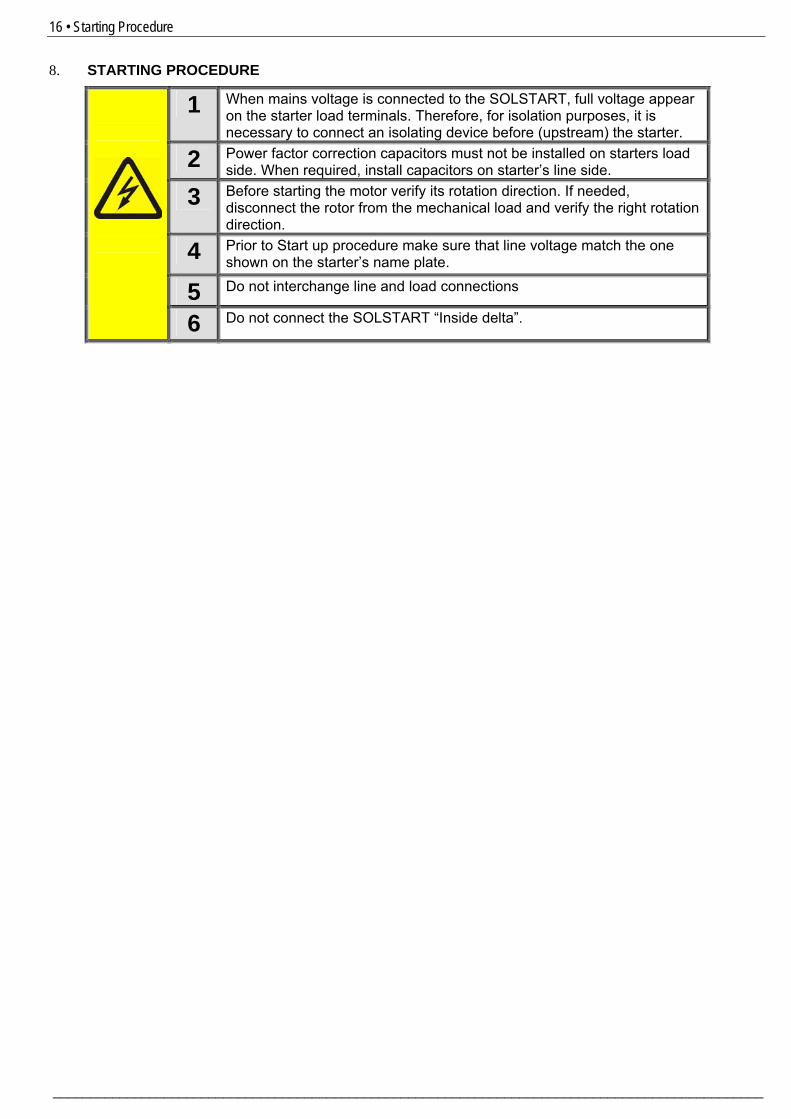
8. STARTING PROCEDURE
1 When mains voltage is connected to the SOLSTART, full voltage appear on the starter load terminals. Therefore, for isolation purposes, it is necessary to connect an isolating device before (upstream) the starter.
2 Power factor correction capacitors must not be installed on starters load side. When required, install capacitors on starter’s line side.
3 Before starting the motor verify its rotation direction. If needed, disconnect the rotor from the mechanical load and verify the right rotation direction.
4 Prior to Start up procedure make sure that line voltage match the one shown on the starter’s name plate.
5 Do not interchange line and load connections
6 Do not connect the SOLSTART “Inside delta”.
________________________________________________________________________________________________

17 • Starting Procedure 8.1 Standard starting procedure
Yes
Motor starts to turn shortly after Start
signal?
No
Initial inrush current or mechanical shock is
too high?
NoIncrease “Initial Voltage” and start again
YesDecrease “Initial Voltage” and start again
1. Set initial voltage potentiometer to mid scale (approx. 40%) 2. Set Ramp-Up potentiometer to approx. 3 seconds. 3. Connect mains voltage to starter line terminals. On LED will
lit. 4. Apply Start command
Apply Stop command and wait until motor stops.
Slightly increase Initial Voltage and Current Limit
settings to allow for load variations.
Apply Start command
If acceleration time is too short, increase Ramp-Up time.
Yes
No Motor acceleration time
to full speed is as required?
End of process
________________________________________________________________________________________________

18 • Starting Procedure
8.2 Examples of starting curves Light loads - pumps, etc. Initial Voltage - set to 40% Ramp-up time - set to 3 sec.
U% 100%
3 t
I% 600%
100%
40%
10%
400% 300%
t
Upon start, the voltage quickly increases to the Initial Voltage value (40% Un) and then gradually ramps-up to nominal. The current will simultaneously increase to peak current value, before smoothly decreasing to the operating current. The motor will quickly and smoothly accelerate to full speed.
________________________________________________________________________________________________
19 • Starting Procedure
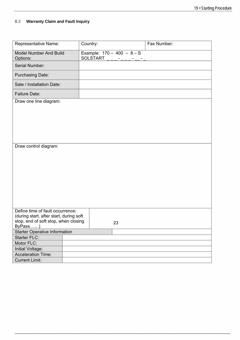
8.3 Warranty Claim and Fault Inquiry
23
Representative Name: Country: Fax Number:
Model Number And Build Options:
Example: 170 – 400 – 8 – S SOLSTART _ _ _ - _ _ _ - __ - _
Serial Number:
Purchasing Date:
Sale / Installation Date:
Failure Date: Draw one line diagram:
Draw control diagram:
Define time of fault occurrence: (during start, after start, during soft stop, end of soft stop, when closing ByPass……)
Starter Operative Information Starter FLC: Motor FLC: Initial Voltage: Acceleration Time: Current Limit:
________________________________________________________________________________________________

20 • Technical Specifications
9. TECHNICAL SPECIFICATIONS
Environment Supply voltage 230 220 - 240 Vac +10% -15%
400 380 - 415 Vac +10% -15% 440 440 Vac +10% -15% 480 460 - 500 Vac +10% -15% 600 575 - 600 Vac +10% -15%
Frequency 50 / 60 Hz Load Three-Phase, Three-Wire, Squirrel
Cage Induction Motor
Degree of protection SOLSTART 8-44A: IP 20 SOLSTART 58-170A: IP 00
Altitude 1000 m above sea level Consult factory for derating Adjustments Starting Torque (Initial Voltage) 10-80 % of full voltage Ramp Up Time (soft start) 0.5 - 5 sec. Ramp Down Time (Soft Stop) 0.5 - 5 sec. Indications
ON - Green Lights when mains is connected to the SOLSTART.
Ramp Up / Ramp Down – Yellow
Lights during Ramp-Up and Ramp-Down
Indication lights (LEDs)
RUN – Green Lights upon end of starting. When the internal bypass relays close.
Temperatures Operating -10° to 40°C Storage -20° to 70°C Relative humidity 93 % - non condensed EMC Immunity to radio electric interference
EN 1000-4-3 level 3 Conforming to EN 60947-4-2
Electrostatic discharge EN 1000-4-2 level 3 Conforming to EN 60947-4-2 Immunity to electrical transients
EN 1000-4-4 level 4 Conforming to EN 60947-4-2
Shock waves of voltage / current
EN 1000-4-5 level 3 Conforming to EN 60947-4-2
Radiated and conducted emissions
EN 1000-4-6 level 3
Radio frequency emissions According to EN 55011 class A Conforming to EN 60947-4-2 Mechanical Shock resistance 8 gn Conforming to EN 60947-4-2 Vibration resistance 2 gn Conforming to EN 60947-4-2 Output relay (Solstart 31-170A only) End of Acceleration Contact N.O. Rated operating current 5 A, 250 VAC - Solstart 31-58A
8 A, 250 VAC - Solstart 72-170A
Solcon Industries Ltd. www.solcon.com; Technical support: [email protected]
________________________________________________________________________________________________