solubility, stability, and electrochemical studies of … stability, and electrochemical studies ......
TRANSCRIPT

' NASA TP
C . I I 1245
NASA Technical Paper 1245
g f
Solubility, Stability, and Electrochemical Studies of Sulfur-Sulfide Solutions in Organic Solvents
William L. Fielder and Joseph Singer
AUGUST 1978
https://ntrs.nasa.gov/search.jsp?R=19780020681 2018-06-02T12:48:04+00:00Z

TECH LIBRARY KAFB, NM
NASA Technical Paper 1245
Solubility, Stability, and Electrochemical Studies of Sulfur-Sulfide Solutions in Organic Solvents
William L. Fielder and Joseph Singer Lewis Research Center Cleveland, Ohio
National Aeronautics and Space Administration
Scientific and Technical information Office
I111111 lllll11111 lllllllHllllll lull Ill1 Ill 01343b2
1978

SOLUBILITY, STABILITY, AND ELECTROCHEMICAL STUDIES OF
SULFUR-SULFIDE SOLUTIONS IN ORGANIC SOLVENTS
by William L. Fielder and Joseph Singer .
Lewis Research Center
SUMMARY
Representatives of many classes of organic solvents (as determined by functional groups) were screened qualitatively for their applicability in a low temperature (100' to 120' C) sodium-suLfur secondary battery system with a dissolved sulfur electrode. Primary screening criteria were the solubilities of Na2S and Na2S2 and the stabilities of the solutions. From this screening and further quantitative Studies, two classes of solvents were selected for further investigation: amides (e.g. , acetamide, N, N- dimethylacetamide, and N, N-dimethylformamide) and cyclic polyalcohols (e. g. , 1,3- cyclohexanediol).
Voltammetric and Na-S cell charge-discharge - studies were made at 120' C with a screened in amide (e. g. , N, N-dimethylformamide) a s the organic solvent and either graphite or platinum as the electrode current collector. The sodium, which was used a s the reference electrode for the voltammetric studies and as the negative electrode for the cell studies, was contained in a sodium beta-alumina ceramic tube. Based on the data, reactions and mechanisms are proposed for the oxidation-reduction processes occurring at the sulfur electrode. Peak voltage differences for each oxidation- reduction reaction were typically 0.3 volt and exchange current densities were
sulfur electrode went to Na2S2, and even to Na2S, it may be possible to achieve the maximum Na-S energy density.
to A/cm2, indicating moderately poor reversibilities. Because the reduction at the
INTRODUCTION
There is a need for high-energy-density secondary battery systems for space and terrestrial applications (e. g. , electric vehicles). The energy-density goals for these systems are about 100 to 200 W-hr/kg and 50 to 100 W/kg.

One battery system being considered is the high-temperature molten Na-S cell, which operates at 300' to 350' C and uses a sodium beta-alumina ceramic as the sodium-ion-conducting separator (ref. 1). However, considerable materials problems are being experienced at these temperatures. Furthermore, the discharge is not al- lowed to go beyond Na2S3 because solid Na2S3 forms; thus the available energy density is only about one-half of the theoretical value for Na2S.
An analogous Na-S cell operating at lower temperatures may be practical because the materials problems should be less severe. This investigation was conducted to determine the feasibility of such a cell. For this cell, both electrodes may have to be in the liquid state, that is, molten o r dissolved to achieve useful current densities; this sets the lower temperature at 98' C - the melting point of sodium. For the sulfur elec- trode, anhydrous solvents must be used because the sulfides react slowly with water to evolve H2S and because water is detrimental to the sodium beta-alumina separator. Organic solvents are investigated in the present work.
Using a n organic solvent to dissolve the sulfur reactants and products adds addi- tional weight to the cell and thereby decreases its energy density. A s a consequence, the ability to discharge this cell from elemental sulfur o r a polysulfide with a high sul- fur content to Na2S (or at least to Na2S2) is highly desirable for obtaining the maximum energy density. High Na2S and Na2S2 solubilities a r e also desirable for practical cell current densities.
Because very little information is available in the literature on the solubilities and stabilities of Na2S o r polysulfides in organic solvents, many classes of organic sol- vents (as determined by functional groups) were screened. The choice of solvents to represent each class was based primarily on their physical properties and availability. For example, 1,4-butanedioI was chosen as representative of aliphatic polyalcohols because it is a liquid at 25' C, has a relatively low vapor pressure at 120' C, and is commercially available at suitable purity (299 percent). For the screening studies, approximate solubilities and stabilities of Na2S and Na2S2 in these solvents were then determined at 120' C . The Na2S and Na2S2 were chosen as representative sulfides because, according to preliminary investigations, they are less soluble in organic sol- vents than the higher polysulfides. Some of the more attractive solvents as suggested by the screening results ("screened-in" solvents) were then investigated further to ob- tain more quantitative measurements of the sulfide solubilities and stabilities. These studies resulted in the selection of two classes of solvents for further work: amides (e. g . , acetamide, N, N-dimethylacetamide, and N, N-dimethylformamide) and cyclic polyalcohols (e. g. , 1,3-cyclohexanediol).
various sodium sulfides in a few of the screened in solvents. In general, voltammo- grams for the sulfur o r sulfide solutions in solvents such as N, N-dimethylformamide
Electrochemical studies were undertaken with solutions of elemental sulfur o r
2
suggested that five sets of oxidation-reduction reactions were occurring during the volt- age scanning from 3.5 to 0 .1 volt (relative to the sodium reference electrode). Peak voltage differences for each of these five reactions indicated moderately poor reversi- bilities on the working electrodes of high-density graphite or platinum. For any prac- tical soluble-sulfur cell, a reasonably large exchange current density (>loe3 A/cm ) is desirable to minimize polarization. However, the values obtained from cell charge- discharge studies, about loW3 to A/cm2, also suggest moderately poor reversi- bilities. Finally, some reactions and mechanisms are discussed for the five proposed reactions, which are as follows:
2
- 6 (S4- + 2e- z 2S2=)
EXPERIMENTAL DETAILS
Preparation and Purification of Materials
Unless otherwise specified, all handling of the materials used in the present in- vestigation (e. g . , solvents, sulfides, and electrode current collectors) and all manipu- lations and operations were performed inside nitrogen o r argon dry boxes to minimize water pickup.
Most of the organic solvents (55) were obtained from the Aldrich Chemical Co. Five solvents were obtained from the Eastman Organic Chemical Co. Most of the sol- vents were used without further purification, particularly for the screening studies. Commercial acetamide, which is a solid at room temperature, was purified further by drying in vacuum over P205 for 1 week and subliming in vacuum at about looo to 120' C .
Elemental sulfur (99.9995 percent pure), Na2S (99.3 percent pure), and Na2S4 (96 percent pure) were obtained from Ventron Corp. and were used without further puri- fication. Neither Na2S8 nor Na2S2 are commercially available. The Na2S2 was pre- pared from a 1:l mixture of Na2S and S (ref. 2). The mixture was ground and sieved
3

(in nitrogen) through a 100-mesh screen. The ground sample was put into a glass am- poule and then removed from the nitrogen dry box. After it was evacuated, the am- poule was sealed and rolled to insure mixing. The mixture was reacted at 250' C (solid state) for 15 to 20 hours and then at 575' C (liquid state) for 1 hour. The am- poule, containing the final product, was then returned to the nitrogen dry box for stor- ing and handling. X-ray diffraction indicated that the reaction product was essentially Na2S2 with a trace of unreacted Na2S and presumably sulfur. No Na2S4 o r Na2S5 was detected .
0.5 molar solution of Na2S4 in N, N-dimethylformamide was placed in a previously dried electrochemical cell (described later) inside an argon dry box. The solution was heated to 120' C, and the Na2S4 was converted to Nagss by passage of the required number of coulombs.
Commercial Na2Sq was used to prepare Na2S8 solutions. A known quantity of a
Commercial, high-purity NaBF4, obtained from Ozark-Mahonning, was used as the supporting electrolyte. It was dried in vacuum at 115' C for about 75 hours and stored in nitrogen.
Various types of graphite were studied as electrode current collectors. High- purity, high-density, nonporous pyrolytic graphite was donated by Union Carbide. Rectangular strips (about 0 . 2 cm by 0 . 3 cm by 4 cm) were cut with a dry diamond wheel so that the largest face was parallel to the graphite plane. The density of the strips was 2.18 g/cm (97 percent of theoretical). The strips were smoothed with a number-400 carborundum paper and then rinsed with acetone and absolute alcohol. After they were dried in vacuum at 450' to 500' C for 1 hour, the strips were redried in vacuum for 6 to 8 hours at 115' C just before use. Porous graphite was obtained from National Co. as spectrographic-grade rods (0.64 cm 0. d.) with a density of 1.94 g/cm (86 percent of theoretical). The rods were dried in vacuum at 115' C for about 6 hours just before use. Graphite felt, obtained from Hitco Corp. , was rinsed with acetone and absolute alcohol and then dried as were the high-density electrodes. For a few experiments, platinum wire (0.08 cm d i m ) and platinum foil (1 cm by 1 cm) were used as electrode current collectors after they were dried at 115' C for 1 hour.
Sodium, contained in a sodium beta-alumina ceramic tube, was used as both the reference electrode for voltammetric studies and as the negative electrode for cell charge-discharge experiments. These tubes; obtained from British Railways, were about 0 .8 centimeter in inside diameter, 1.1 centimeters in outside diameter, and 17 centimeters in length. They were dried at 900' C for 1 hour inside an argon dry box. Sodium was added to the tubes after they were cooled and then was heated to about ZOOo to 250' C to wet the ceramic.
3
3
4

Solubilities and Stabilities
For the screening experiments, Na2S o r Na2S2 and 1 0 to 15 milliliters of an or- ganic solvent were put into a glass ampoule inside the nitrogen dry box. This quantity of sulfides was sufficient to yield a 1- to 2-molar solution if all of the solids dissolved. The stoppered ampoule was removed from the dry box and the sulfide-solvent mixture was frozen with dry ice. After the ampoule was outgassed, it was sealed under vac- uum. The sample was heated to 120' C and the sulfide solubilities were estimated from the volume of the undissolved solids o r from the color and appearance of the solu- tion. Any reactions were noted by visual observation of any gas evolution or phase or color changes .
Two methods were used to determine the quantitative solubilities of the sulfides in several screened in solvents at 130' C : one method involved weighing the undissolved solid residue, and the other method involved chemically analyzing the saturated solu- tion. Occasionally both methods were used for a particular sample. In the residue method, a known quantity of the sulfide was heated with 1 0 to 15 milliliters of the sol- vent in a tared beaker inside the nitrogen dry box. Simultaneously, a tared coarse- glass frit was preheated to 80° to 110' C to minimize sulfide precipitation during the filtration. The slurry was suction filtered and the undissolved solid residues (in the beaker and on the frit) were rinsed with three 10- to 15-milliliter rinses of absolute alcohol to remove occluded liquor. Auxiliary tests showed that less than 5 percent of the sulfide was lost in these rinses. After the system was evacuated to remove the residual rinse alcohol, the beaker and frit were reweighed t o give the quantity of un- dissolved sulfide.
The apparatus shown in figure 1 was used to determine the sulfide solubilities by chemical analysis of the saturated solutions. Excess sulfide was added to the appara- tus along with about 15 to 20 milliliters of the solvent. After the stopcock was closed, the apparatus was removed from the nitrogen dry box and the mixture was heated to 130' C . A sample of the saturated liquor was pipetted into a small, capped weighing bottle for chemical analyses. Exposure of the sample to moisture would lead to slow evolution of H2S. Therefore, the exposure time during sampling was kept to a mini- mum, and the sample was then introduced directly into an aqueous hydroxide solution for analysis.
Before sampling, the stability of the solution was determined at 130' C in the ap- paratus of figure 1 by observing any gas evolution o r phase o r color changes. Occa- sionally, H2S evolution occurred after an initiation period of 1 to 3 days. Consequently, most of the solutions were observed for at least 3 to 4 days unless gas evolution started earlier. The presence of H2S was detected with lead acetate paper.
5

Figure 1. -Apparatus for determining solubilities and stabilities of su Ifide-solvent mixtures.
Electrochemical Measurements
A three-electrode glass cell, shown in figure 2, was used for the voltammetry ex- periments. The working-electrode current collectors were high-density pyrolytic graphite, porous graphite, o r platinum wire. The counter-electrode current collec- to rs were usually graphite felt and occasionally platinum foil (with the platinum wire). A coarse-glass frit was placed between the counter- and working-electrode compart- ments to minimize diffusion of a species from one compartment into the other. The reference electrode was sodium contained in a sodium beta-alumina tube versus a fixed concentration of sodium ions in the sulfide solution. The NaBFq, when added to the solution as the supporting electrolyte (0 .1 M), fixed the sodium ion concentration.
box. The brass fittings, which contained fluorocarbon (or silicone) O-rings, were closed to preserve the argon atmosphere introduced into the cell. The cell, still in- side the argon dry box, was then heated at 120' C for about 15 minutes. Any gas pres- sure buildup was relieved by momentarily loosening the O-ring fitting. The cell was then held at 120° C for about 2 hours before voltammograms were obtained.
The desired sulfur o r sulfide solution was placed into the cell inside the argon dry
6

Na reference Stainless-
pressure ----
Counter electrode ( C o r PT ------
Glass f r i t - ' ' ~ W o r k i n g electrode (C or Pt)
Figure 2 - Three-electrode voltammetry cell.
The three-electrode cell leads were connected to a Wenking potentiostat. The voltage sweeps were obtained by using a Tacussel triangular wave signal generator. The solution'was scanned at various rates over the desired voltage ranges relative to the sodium reference electrode. The currents were measured by means of the voltage developed across a standard resistor in series with the cell. Plots of current versus voltage were obtained with an X-Y recorder.
electrode cell, was used for the cell charge-discharge experiments. The electrodes were high-density graphite and liquid sodium (contained in the sodium beta-alumina tube). A supporting electrolyte of NaBF4 (0.1 M) was usually added to decrease the cell resistance. A known quantity of the sulfur o r sulfide solution was placed into the cell (inside the argon dry box). Any gas pressure buildup was relieved and the cell was then held at 120° C for 1 to 2 hours. The open-circuit voltage of the cell was noted, and the corresponding cell voltages were measured at various current loads during cell charge o r discharge. 3 V) was applied from a precision direct-current power supply connected in series with the cell. About 30 to 60 seconds were usually sufficient to obtain an equilibrium cell voltage at each current load. The currents w e r e measured by means of the voltage developed across an external standard resistor. The current densities were estimated from the currents and from the apparent electrode surface wetted by the solution. The
The two-electrode cell, which is essentially two compartments of the three-
For cell charging, an opposing constant voltage (2 to
7

cell current-resistance (IR) polarization was usually obtained by extrapolating the straight-line portion (i. e . , the higher current portion) of a current-voltage curve to zero current. Cell polarizations were estimated from the cell voltages and the cell IR polarizations.
RESULTS AND DISCUSSION
For simplicity, most of the data are presented in the appendixes. The solubilities and stabilities of sulfides in many classes of organic solvents, obtained during the screening process, are given in appendix A. The voltage peaks obtained for the five sets of sulfur-sulfide oxidation-reduction reactions by using various sulfur starting materials, solvents, and electrode current collectors a re given in appendix B . The Tafel equation calculations for the various mechanisms that could be involved in the oxidation and reduction reactions are given in appendix C . Additional data a re pre- sented in the main text: Table I contains some quantitative solubility and stability mea-
TABLE I. - QUANTITATIVE SOLUBILITIES AND STABILITIES O F
Na2S, Na2S2, AND Na2S4 AT 130' C
Solvent
Acetamide
N, N-Dimethylacetamide
N, N-Dimethylformamide
Formamide
Sulfide
Na2S
NazS2 Na2S4
Na2S
Na2S4 Na2S2
Solubility, M
1.0 .8
1.4
0.007 .03
1 .5
0 .3 . 9
1 .5
<o. 01 .12
.95
Method of determination
Residue Residue S analyses
Na analyses Na, S analyses Na, S analyses
Residue Residue Residue
Residue Residue; Na, S, and
Residue; S analyses s = analyses X
Remarks
Stable at 130' C
Stable at 130' C Stable at 130' C Stable at 130' C
------------__ H2S evolved after
H2S evolved after 3 days at 130° C
3 days at 130' c
H2S evolved after 3 hours at 130' C
8

-
TABLE II. - OXIDATION-REDUCTION OF ELEMENTAL SULFUR AND SODIUM SULFIDES
First
Second
Third
Fourth
Fifth
Reactions
sg0 + 2e- z s8=
Mechanisms
Reduction
2 s80 + le- z(s8-)] RDS [ 2(Sg-) : S80 + sg=
sg= z 2(s4-)
[ -1 2 [(Sc) + le- z s4=]
2 s4= + sg= z 2s6-
RDS
s6= z 2(53-)
2[(S3-) + le- z s3=]
2s3= + s6= z 3s4=
RDS
s4= z 2(s2-)
2[(s2-) + le- z s2=] RDS
Oxidation
2[s8= z (S8-) + le-] RDS
2kg-) f S80 + sg=
2 2s6= z sg= + s4=] [
2 @ q ) f sg=
2[s4= z (SL) + le-] RDS
- 3s4- z s6= + 2s3=
2 b3= z (S;) + le-] RDS
2 t3 - ) : s6=
4 2s= z s2-
s2-4 z ( s 2 - 3 ) + le-
( ~ ~ - 3 ) : s2= + le-
surements for some of the sulfides in a few screened in solvents. Table I1 summarizes the five sets of proposed oxidation-reduction reactions and mechanisms.
Solubilities and Stabilities
For useful sodium-soluble-sulfur cell current densities, the discharge products should have adequate solubilities (0.5 M o r greater) to minimize the formation of high- resistivity films by excessive precipitation of the sulfides on the sodium beta-alumina
9

ceramic o r on the sulfide electrode current collector. Many classes of organic sol- vents were screened. All the solvents could be classified into five groups, as shown in appendix A. The solvents in group 1 gave moderately high solubilities ( - 0 . 5 to 2 M) for both Na2S and Na2S2 at 120' C . Group 1 includes the following classes: alcohol- amines, amides, cyclic alcohols, glycols, aliphatic polyalcohols, and cyclic poly- alcohols. In subsequent tests, gas-bubble formation showed aliphatic polyalcohol and glycol solutions to be generally unstable.
Group 2, a somewhat larger group of solvents, gave poor-to-moderate solubilities for Na2S and Na2S2 at 120' C. The solubilities were estimated from the solution color a s well a s from the quantity of remaining undissolved solids. Soluble polysulfides gen- erally give highly colored solutions in organic solvents (ref. 3). Group 2 includes alcohol-ethers, amides (aliphatic, cyclic, and phosphorous), cyclic ketones, lactones, sulfolanes, and sulfoxides.
Group 3 contained three solvents that formed gels or slurries with Na2S and Na2S2 at 120' C. Because the undissolved solids did not settle rapidly, solubility estimates were difficult to make. Additional investigations would be necessary to determine whether this gel o r slurry formation is specific to that particular solvent o r is repre- sentative of its class.
The majority of the organic solvents were less desirable. The group 4 solvents gave poor Na2S o r Na2S2 solubility. And several group 5 solvents reacted with Na2S and Na2S2, usually to evolve H2S.
ments, were the amides and cyclodiols of group 1 and the amides, lactones, sulfolanes, and sulfoxides of group 2 . Quantitative solubility and stability measurements were then made at 130' C for a few of these screened in solvents, and the results are given in ta- ble I. Two amide solutions (acetamide and N, N-dimethylacetamide) and the cyclodiol solution (1,3-cyclohexanediol) seemed to be stable. (N, N-dimethylformamide and formamide), however, were less stable and evolved H2S after an initiation period. Only one solvent in table I (i. e. , acetamide) was dried. Evolution of H2S for two of the solvents (i. e., formamide and N, N-dimethylformamide) might have been due to traces of water contamination.
The solubilities of Na2S and Na2S2 at 130' C are in fair agreement with the values obtained by Brummer at 150' C (ref. 4). He obtained Na2S and Na2S4 solubilities of 1.19 and 1.59 molar, respectively, in acetamide and 0.0075 and 1.33 molar, respec- tively, in N, N-dimethylacetamide. The solubility of Na2S in N, N-dimethylformamide (<O. 0 1 M) is somewhat less than Brummer' s value of 0.05 molar at 150' C. Of the five solvents studied quantitatively, acetamide and 1,3-cyclohexanediol may be more useful for low-temperature sodium-sulfur cells than for high-temperature cells be- cause the solubility of Na2S (usually the least soluble species) is still relatively high.
The more promising classes of solvents, a s suggested by the screening experi-
The other two amide solutions
10
Electrochemical Results
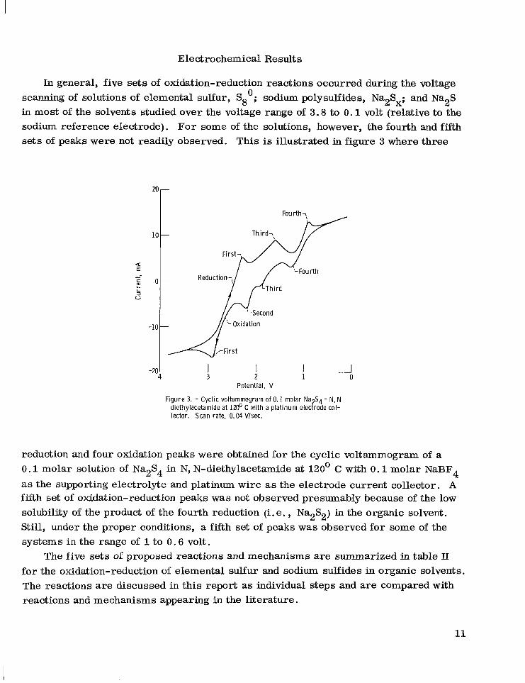
In general, five sets of oxidation-reduction reactions occurred during the voltage scanning of solutions of elemental sulfur, Sg0; sodium polysulfides, Na2Sx; and Na2S in most of the solvents studied over the voltage range of 3.8 to 0 . 1 volt (relative to the sodium reference electrode). For some of the solutions, however, the fourth and fifth sets of peaks were not readily observed. This is illustrated in figure 3 where three
Third-,
First-
Fou rth Reduction-,
Th i rd
a E -- I I
V
I -20 4
I 3
I 2 u 1 0
Potential, V
Figure 3. - Cyclic voltammogram of 0.1 molar Na S4 - N, N- diethylacetamide at 1200 C with a plat inum electrode col- lector. Scan rate, 0.04 Vlsec.
reduction and four oxidation peaks were obtained for the cyclic voltammogram of a 0 . 1 molar solution of Na2S4 in N, N-diethylacetamide at 120' C with 0 .1 molar NaBFq as the supporting electrolyte and platinum wire a s the electrode current collector. A fifth set of oxidation-reduction peaks was not observed presumably because of the low solubility of the product of the fourth reduction (i. e. , Na2S2) in the organic solvent. Still, under the proper conditions, a fifth set of peaks was observed for some of the systems in the range of 1 to 0 . 6 volt.
The five sets of proposed reactions and mechanisms are summarized in table 11 for the oxidation-reduction of elemental sulfur and sodium sulfides in organic solvents. The reactions are discussed in this report as individual steps and are compared with reactions and mechanisms appearing in the literature.
11
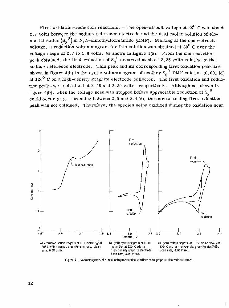
First oxidation-reduction reactions. - The open-circuit voltage at 30' C was about 2 . 7 volts between the sodium reference electrode and the 0 . 0 1 molar solution of ele- mental sulfur S in N, N-dimethylformamide (DMF). Starting at the open-circuit voltage, a reduction voltammogram for this solution was obtained at 30' C over the voltage range of 2 . 7 to 1 . 6 volts, as shown in figure 4(a). From the one reduction peak obtained, the first reduction of S80 occurred at about 2.25 volts relative to the sodium reference electrode. This peak and its corresponding first oxidation peak are shown in figure 4(b) in the cyclic voltammogram of another S8'-DMF solution (0.001 M) at 120° C on a high-density graphite electrode collector. The first oxidation and reduc- tion peaks were obtained at 2.45 and 2.30 volts, respectively. Although not shown in figure 4(b), when the voltage scan was stopped before appreciable reduction of S8
could occur (e. g. , scanning between 3.0 and 2.4 V), the corresponding first oxidation peak was not obtained. Therefore, the species being oxidized during the oxidation scan
( 8O)
0
J 3.0 2.5 2.0 1.5 3
oxidation 2'
I 2.5
2 3.0
Potential, V
First reduction7
3
(a) Reduction voltammogram of 0.01 molar S t a t (b) Cyclic voltammogram of 0.001 C with a porous graphite electrode. Scan molar S t a t 1200 C wi th a
h igh-density graphite electrode. Scan rate, 0.02 Vlsec.
rate, 0.08 Vlsec.
First reduction
oxidation
I 2.0
.~ I 25
I 3.0
(c) Cyclic voltammogram of 0.007 molar N a g at 12@ C with a high-density graphite electroze. Scan rate, 0.01 Vlsec.
Figure 4. - Voltammograms of N. N-dimethylformamide solutions wi th graphite electrode collectors,
12

must have been produced during the preceding reduction scan.
polysulfide solutions as starting materials. For example, after a few cycles over the entire voltage range of 3.5 to 0 .1 volts, the first oxidation-reduction peaks were read- ily seen upon subsequent cycling through the first oxidation-reduction range of 3 .5 to 2.25 volts. This is illustrated in figure 4(c) for a dilute Na2S2-DMF solution, where the first oxidation-reduction peaks were obtained at 2.55 and 2.35 volts, respectively. A s shown in figure 4(c), the f i r s t oxidation peak was greatly decreased if the reduction sweep was limited to 3.5 to 2.45 volts.
The peak voltages for both the oxidation and reduction reactions were related to the voltage scan rate as shown in figure 5. Essentially straight lines were obtained for a plot of these vqltages versus the square root of the scan rate by using various sulfide starting materials on both porous and high-density graphite electrodes. A scan rate of about 0 . 0 1 to 0.02 V/sec was usually sufficiently slow to give peaks at about 2.6 and 2 . 3 volts, respectively, for the first oxidation-reduction reactions for most of the solutions. The results are shown in appendix B.
0 .01 to 0.02 V/sec indicate the reversibility of the process: A system is considered to be reversible if the difference in the peak voltages is approximately 0.05 volt (ref. 5).
These first sets of oxidation-reduction reactions can also be obtained with other
The voltage differences between the first oxidation and reduction peaks at about
3.5 I Sulfide Solvent
0 58' N.N-Dimethyl- formam ide
u Sg0 1.4-Butanediol 0 Na2S8 N, N-Dimethyl-
formamide
formamide
formamide
A Na2S4 N. N-Dimethyl-
0 Na2S2 N, N-Dimethyl-
Electrode Temperature,
co I I ector
graphite
cur ren t OC
High-density 30, 120
Porous graphite 30 High -density M
High -density M
High -density 120
graphite
graphite
graphite
w - - 3.0 t 0
I / >
1.6 1.8 2.0 I I
1.2 1.4 I I
(Scan rateP2, ( V / s e c P 1.0 .8
I .6
I . 4
I .2
1.5 I 0
Figure 5. - Peak voltages with scan rates for oxidation-reduction reactions.
13

For these first oxidation-reduction reactions, the difference of about 0 . 3 volt obtained for the two peaks for both solvents and for both graphite electrodes suggests that the reversibility was moderately poor at 120' C.
120' C in Na-S cells. One cell had N, N-dimethylformamide as the solvent and high- density graphite (HDG) as the electrode current collector, as follows:
The reduction of elemental sulfur, the f i r s t reduction reaction, was investigated at
Na(l)l sodium beta-alumina] 0.004 M Sg0 - DMF(O.1 M NaBF4) - (HDG)
Discharge Instrument time, SeC
The current-voltage plot for discharging the cell is shown in figure 6 . The cell resis- tance was estimated from an extrapolation of the straight-line portion of the curve
(i. e. , the higher current portion). Although the resistance for this cell was about 130 ohms, the resistances for most of the cells were 20 to 30 ohms. Because the liquid-sodium electrode should be reversible at 120' Cy the calculated cell polarization (after accounting for the IR polarization) was assumed to represent the activation polar- ization of the sulfur electrode. This polarization was then plotted against the cell cur- rent density (Tafel plot) as shown in figure 7 , giving a slope of 0 . 3 6 volt per decade. Extrapolating the straight-line portion of the data to zero polarization gives an apparent exchange current density of about A/cm2. Keeping in mind our cyclic voltammo- gram result, we interpret this relatively low exchange current density to be indicative of a moderately poor reversibility for the first reduction reaction of sulfur on high-
14

Discharge time,
S K
0 #)tobo O M
Instrument 0
Voltmeter
LSlope, 0.36 Vldecade
Cur ren t density, AlcmZ
0.004 molar S$ - N. N-dimethylformamide cel l at 1200 C with a high-density graphite electrode collector.
Figure 7. -Tafel lot of discharging of a Na(l)/sodium beta-alumina/
density graphite. platinum, have exchange current densities A/cm (ref. 6). ) Furthermore, this low current density practical soluble sulfur cell operating at acceptable currents. For example, at cur- rents of 25 to 50 mA/cm , an exchange current density of greater than be required to limit polarization to less than 0.2 volt.
cell contained lY4-butanediol as the solvent with platinum wire as the electrode current collector; the other cell contained N, N-dimethylformamide as the solvent with porous
8 graphite as the electrode current collector. Averaging the slopes for all three S 0 cells gave a value of 0 . 3 9 for the first reduction reaction of S8 .
A solution of Na2S8 in DMF was used to study the first oxidation reaction. Be- cause Na2s8 was not available commercially, it was prepared in situ by oxidation electrolysis of a 0.5-molar solution of Na2S4 at 120' C (using high-density graphite) in the following cell:
(More reversible systems, such as the evolution of hydrogen on
2 2
A/cm ) may lead to excessive polarization losses for any
2 2 A/cm may *
Two additional cells containing elemental sulfur were discharged at 120° C: One
0
Na(l ) l sodium beta-alumina1 0 .5 M Na2S8 - DMF - (HDG)
The current-voltage curve data gave a cell resistance of 28 ohms. The Tafel plot is shown in figure 8. A slope of 0.18 volt per decade and an exchange current density of
15

.15
0 a
.05
0 10-4
d 0.18 Vldecade 7,
Slope. d’ Current density, A h Z
Figure 8. - Tafel plot of charging of a Na(2)l sodium beta-alumina10.5 molar Na& - N. N-dimethylformamide cell at 1% C with a high-density graphite electrode collector.
2 l o y 3 A/cm were obtained for this first oxidation reaction. The overall reaction for the initial reduction of elemental sulfur (i. e . , the first
- - reduction reaction) is the reduction to S as follows: 8
sg 0 + 2e- z sg=
By using the method reported by Fraser (ref. 7) and Del Duca (ref. 8 ) , Tafel slopes (obtained from the Tafel plots) ye re used to calculate the electron transfer coefficients p . For example, the average Tafel slope, obtained from discharging cells containing Sg0, was 0 . 3 9 volt per decade. This slope was used to calculate p fo r various pos- sible mechanisms (appendix C). Mechanisms giving P closest to 0.5, the theoretical
0 value, were then assumed to be more likely f o r the first reduction mechanism of S8 . Among those mechanisms considered, we believe the following one-electron transfer and disproportionation steps are more likely because they gave a calculated p of 0.8:
- - 2(Sg-) z S8 0 + S8
This mechanism is given in appendix C as equations (1) and (2); equation (1) is the rate-determining step (RDS). The step involving the addition of one electron to the
16

S8' species for the rate-determining step seems intuitively more plausible because it involves the breaking of a Ss0 ring. The radical S8 tionate to form Sg0 and S8 .
Two alternative reduction mechanisms also gave /3 of 0.8 and cannot be rejected categorically. However, we believe that these mechanisms are more difficult and less likely. One mechanism (eqs. (3) and (4) in appendix C) involves two consecutive one- electron transfer steps. The other mechanism (eqs. (5) and (6)) may require an ap- preciable concentration of the final product, S8 , before reduction of the radical S8 can occur to produce S8 .
species may then dispropor- - - ( -)
- - - - -
A similar reaction is proposed for the corresponding f i r s t oxidation reaction:
s8= z s80 + 2e-
The Tafel slope of 0.18 volt per decade, obtained from the charging of a Na2S8 C e l l , was used to calculate p for various oxidation mechanisms (table in appendix C). Among those mechanisms, we believe the following (eqs. (8) and (9)) are more likely for the first oxidation reaction because they gave a calculated p of 0.4.
2(S&S8 0 +s8=
Two other mechanisms also gave p of 0.4 but are considered to be less likely for reasons similar to those given for the first reduction process. One of these mecha- nisms (eqs. (10) and (11)) may require an appreciable concentration of the final product, S80, before oxidation of the radical S
(eqs. (12) and (13)) involves two consecutive one-electron transfer steps.
oxidation-reduction reactions. studied the cyclic voltammetry (using a calomel electrode as the reference) and elec- trolysis of a solution of elemental sulfur in methyl sulfoxide on gold at room tempera- ture. They obtained peaks for the f i r s t oxidation-reduction reactions at -0.3 and -0.6 volt, relative to the calomel electrode. These values correspond to about 2 . 6 and 2 . 3 volts, relative to the sodium reference electrode, which is in good agreement with the present investigation. They also found that two electrons were passed for each Sg0 reacted, which suggested that Ss0 was reduced to S8 . A similar reaction was ob- served by Kennedy (ref. 11) for a solution of elemental sulfur in fused LiC1-KC1 at 420' C. Controlled reduction electrolysis at his first reduction voltage gave 0.265
can occur. The other oxidation mechanism ( s-> Similar reactions have been obtained by other investigators for these f i r s t
For example, Merritt (ref. 9) and Martin (ref. 10)
- -
17

0 electron for each sulfur atom (two electrons per S8 ) .
Other investigators have suggested that this first reduction mechanism is bielec- tronic (i. e . , a two-electron transfer step) (ref. 9). This mechanism is shown in ap- pendix C as equation (7). However, this two-electron transfer mechanism is probably less likely than the proposed one-electron transfer mechanism. First, a two-electron mechanism for this first reduction is not expected intuitively: A one-electron transfer would seem more reasonable. Furthermore, although Merritt (ref. 9) presented a two- electron step for the reduction of Sao to S8 , his data led to an n (i. e . , the number of electrons transferred) considerably less than 2 . For example, n = -1 .4 if 0 . 5 is as- sumed for the electron transfer coefficient. Finally, this two-electron mechanism for the first reduction reaction seems less likely because its calculated p of 0 . 9 is some- what larger than the p calculated for the one-electron transfer mechanism.
The corresponding first oxidation mechanism suggested by previous investigators is less clear. Essentially, they have suggested that the reverse of the first reduction reaction occurs by a two-electron mechanism. However, such a two-electron transfer mechanism (appendix C, eq. (14)) is probably less likely because its calculated ,6 of 0.2 is considerably smaller than the ,8 obtained for the proposed one-electron trans- fer mechanism.
Second and third oxidation-reduction reactions. - The species obtained during the first reduction reaction can be reduced further by extending the voltage sweeps to less than 2 . 3 volts relative to the sodium reference electrode. This is illustrated in figure 9(a) for a cyclic voltammogram of a dilute solution of elemental sulfur, sg0, in N, N- dimethylformamide where the voltage was cycled between 3 . 6 and 1 . 3 volts. A s ex- pected, the first oxidation-reduction peaks were observed at about 2 . 6 and 2 . 3 volts, respectively. Three additional peaks were obtained for this solution: a reduction peak at 1.55 volts, labeled the third reduction peak; and two oxidation peaks, a small peak at 2 . 1 volts and a larger one at 1.75 volts. These oxidation peaks have been labeled the second and third oxidation peaks, respectively. The corresponding second reduc- tion peak was not observed, presumably because it is overshadowed by the nearby larger first o r third reduction peaks. Straight lines were obtained for a plot of eak
Most polysulfide solutions (after only a few initial cycles between 3 . 5 and 0 . 1 V) also gave similar peaks for these second oxidation and third oxidation-reduction reactions. For example, as shown in appendix B, the S80 and polysulfide solutions gave the sec- ond oxidation peak at about 2 . 2 volts and the third oxidation-reduction peaks at about 1 .9 and 1 . 6 volts, respectively, relative to the sodium reference electrode. This peak difference of 0 . 3 volt for the third oxidation-reduction peaks suggests that the reversi- bility of these reactions was moderately poor at 120' C .
- -
voltages for the third oxidation-reduction reactions as a function of (scan rate) 172 .
18

Fourth
0 I
3 2 1 2 1 Potential, V
(a) 0.002 Molar Sg0 in N, N-dimethylformamide; (b) 0.1 Molar Na S4 in N. N- high-density graphite electrode collector. diethylacetami& plat inum
electrode collector.
Figure 9. - Cyclic voltammograms for amide solutions at lZ@ C. Scan rate, 0.02 Vlsec.
The second reduction mechanism was then investigated at 120° C with a high- density graphite electrode by discharging a cell containing a 0 . 5 molar solution of Na2S8 in N, N-dimethylformamide:
Na(l)l sodium beta-alumina) 0 .5 M Na2S8 - DMF - (HDG)
The Tafel plot for this cell gave a slope of 0.29 volt per decade and an exchange cur- rent density of about 2
The third oxidation reaction was studied by charging cells containing solutions of Na2S4'at 120° C . For the first cell, HDG and DMF were used; and for the second cell, porous graphite (PG) and N, N-diethylacetamide (DEA) were used. The cells were a s follows :
A/cm2.
Na(l) 1 sodium beta-alumina 10.9 M Na2S4 - DMF - (HDG)
Na(L)I sodium beta-alumina1 0 . 1 M Na2S4 - DEA - (PG)
Tafel plots for the f i r s t and second cells gave slopes of 0.16 and 0.13 volt per decade, respectively. An exchange current density of about 3 x l 0 - ~ A/cm was obtained for the first cell. This relatively low exchange current is probably indicative of moderately
2
19
poor reversibility of the third oxidation-reduction reaction, as supported by the cyclic voltammetry results.
W e propose the following overall reaction for the second reduction:
The Tafel slope of 0.29 was used to calculate the electron transfer coefficient p by assuming various mechanisms for the second reduction reaction (appendix C). Three mechanisms, involving one-electron transfer steps, gave a calculated p of 0 . 7 . The following mechanism (eqs. (15) to (17)) is favored because it is simpler:
2 [I sq= + s8= z 2sg=]
This mechanism is supported by the fact that certain divalent polysulfides dissociate to form radical species (ref. 3) . Consequently, an equilibrium between S 8 and the radi- tal (Sq-) species might be expected. And the subsequent equilibrium between S6 and the two species of S4 and S8 is supported by an observation of Martin (ref. 10) . He found that the spectrum for an S6 solution was similar to that obtained for a mixture of S8 and S4 solutions. The other one-electron transfer mechanisms are probably less likely: One mechanism (eqs. (18) to (21) in appendix C) requires a combination of the (S4-) radical with the S8 before the rate-determining step (eq. (20)) can occur; the other mechanism (eqs. (22) to (25)) requires the reduction of the S20 species in preference to its combining to form S8 .
We made no attempt to follow the corresponding second oxidation reaction by charging a cell containing Na2Ss. However, it seems reasonable to propose that this second oxidation mechanism is the reverse of the corresponding second reduction pro- cess.
- -
- - - - - -
- -
- - - -
- -
0
- 2 p6- z s8= + sq=]
20

- - For the third reduction reaction, the S6 species (produced during the second
- - reduction reaction) is subsequently reduced to S4 . And the corresponding third oxida- tion reaction is assumed to be the reverse, as follows:
The Tafel slope of 0.15 volt per decade, obtained a s an average value from the charging of two Na2S4 cells, was used to calculate an electron transfer coefficient p for various assumed third oxidation mechanisms. Four mechanisms gave a calculated p of 0 . 5 . The following one-electron transfer mechanism (eqs. (26) to (28) in appendix C ) is favored:
- 3s4- 2 s6= + 2s3=
2(s3-) z s6= - - - -
This disproportionation of the S4 species seems analogous to that - - occurring for S 6 .
Furthermore, the equilibrium between the (S3- ) radical and S6 is well known (ref. 12).
Thus any ( S 3 - ) produced by the oxidation of S3- can form the final product of S6-. Two of the one-electron mechanisms seem unlikely: One (eqs. (32) to (35)) requires the formation of an S12-6 species before oxidation can occur; the other mechanism (eqs. (36) to (38)) requires a preferential reaction of any S20 species to form S6 rather than combining to form S8 .
- -
- -
0
We assume that the third reduction mechanism (i. e . , the reduction of is the reverse of the third oxidation mechanism and propose the following:
s6= to s4=)
s6= z 2 (SQ-)
Widely differing reactions and mechanisms have been suggested by other investi- gators for the second and third oxidation-reduction reactions. (ref. 10) obtained a small oxidation peak (at -0.7 V, relative to the calomel electrode) between the first and third set of peaks but attributed this peak to the oxidation of a pro- tonated species. This value of -0.7 volt is in reasonable agreement with the present
For example, Martin
2 1

investigation and corresponds to about 2 .1 volts relative to the sodium reference elec- trode. Martin' s third oxidation-reduction peaks were also in reasonable agreement with the present investigation and correspond to about 1 .7 and 1.6 volts, respectively, relative to the sodium reference electrode. Martin labeled these peaks as the second waves. He showed that S4 was the product of this third reduction reaction and pro- posed a two-electron transfer mechanism for this reduction step. Bonneterre also studied the reduction of elemental sulfur, SSo, in methyl sulfoxide (ref. 12). Unlike Martin, he did not obtain the second oxidation-reduction peaks but did observe the presence of S6 . He suggested that the S8- species, produced during the first reduc- tion of S80 , disproportionated as follows:
- -
- - -
0 , l 0 s2 + - S g 4
W e suggest that our proposed second reduction reaction can explain the presence - -
of S6 more readily than Bonneterre' s disproportionation reaction. In support of this, S6 was produced electrochemically. For example, Martin indicated that current con- tinued to flow even after the SSo had been reduced by two electrons. After 2.7 elec- trons (or eight electrons per 3S8 ) had been passed, the spectrum of the solution was similar to that obtained for a solution of Na2S6, implying an end product of S6 . Bonneterre observed the visible spectrum of S80 near his first reduction voltage. If
8 S8 should have been present as soon as S 6 was being produced electrochemically in the first reduction reaction. However, Bonneterre found that only the S8 species was present until two electrons had been passed per S8 . No S6 was produced during this time. Continued electrolysis led to a decrease in the formation of S8 with a corresponding increase in the formation of S6 . Finally, after 2 . 7 electrons had been passed per S g 0 , the S8 species was no longer present and the S6
Badoz-Lambling also studied the reduction of S80 in methyl sulfoxide (ref. 13). In agreement with the present investigation, he suggested that the third reduction reaction was involved in the continued reduction of S6 to S4 . He implied that the mechanisms for both the third oxidation and reduction reactions involved a two-electron transfer step. However, we suggest that this two-electron mechanism is less likely than our proposed one-electron mechanism. In support of this, the calculated @ for the two- electron mechanism (eqs. (42) and (43) in appendix C) is about 0.3, but the @ for our proposed one-electron transfer mechanism for this third oxidation step is about 0.5.
- -
0 - -
- - - - - - - - was disproportionating to S6 , some S
- -
- - 0 - -
- - - - - -
species had increased to its maximum.
- - - -
22
I

- - - Fourth oxidation-reduction reactions. - Reduction of the S4- species to S2 oc-
curred in a 0.1-molar solution of Na2S4 in N, N-dimethylacetamide on porous graphite. Starting at its open-circuit voltage, the voltage was swept to about 0 . 1 volt relative to the sodium reference electrode. A broad reduction peak was obtained, with its maxi- mum at about 0 .8 volt. Since the S4 should be the primary species in the solution, it is assumed that this fourth reduction process involves the reduction of S4 to S2 . The fourth set of peaks were also seen in the cyclic voltammograms at 120° C for a 0.1- molar solution of Na2S4 in N, N-diethylacetamide with platinum as the electrode current collector. A s shown in figure 9(b), sweeping between 2 and 0 .2 volts gave the fourth oxidation-reduction peaks at 1.25 and 0.85 volts, respectively. Other sulfide solutions gave similar peaks. However, the peaks often were small and difficult to see because Na2S2 and Na2S have smaller solubilities in most of the solvents studied. Some of the data for these fourth peaks are given in appendix B. The various solutions gave the fourth oxidation-reduction peaks at about 1 .3 and 0.9 volts, respectively. This peak difference of about 0 . 4 volt suggests that the reversibility for these oxidation-reduction reactions was rather poor on either platinum o r graphite at 120' C .
Although other investigators have had difficulty in observing these fourth (or fifth) oxidation-reduction peaks in aprotic solvents, the reduction of sulfides to S2 was ob- served in polysulfide melts and in solutions of sulfides in fused salts (refs. 11, 14, and 15).
In the present investigation, the fourth reduction reaction was then followed by discharging at 120° C a cell containing a 0.9-molar solution of Na2S4 in N, N- dimethylformamide on high-density graphite:
- - - - - -
- -
Na(L )I sodium beta-alumina1 0 . 9 M Na2S4 - DMF - (HDG)
The Tafel plot for this cell gave a slope of 0.16 volt per decade and an exchange current density of about ~ > c L o - ~ A/cm2. A similar cell of 0 . 1 molar Na2S4 in N, N- diethylacetamide (on platinum) gave a slope of about O . 22 volt per decade. The average for the two cells was 0.19 volt per decade.
The overall fourth oxidation-reduction reaction is assumed to be
The electron transfer coefficients ,f3 were then calculated (appendix C ) for various fourth reduction mechanisms. Three mechanisms gave a ,f3 of 0 . 6 . The following mechanism (eqs. (44) and (45)) is favored because it is simpler:
23

The two additional one-electron transfer mechanisms giving p of 0 .6 are thought to be less likely: One mechanism (eqs. (46) to (48)) requires two consecutive one-electron transfer steps; the other mechanism (eqs. (49) to (51)) requires the reduction of SZo in preference to its combining to form s8 . The two-electron mechanism (eqs. (52) and ( 5 3 ) ) seems less likely because it gave a larger p of about 0.8.
of the fourth reduction mechanism:
0
- We assume that the fourth oxidation mechanism (i. e . , S2- to S4=) is the reverse
2 (sg-) z s4=
Fifth oxidation-reductio?-reactions ~ _ _ . - A s mentioned previously, no fifth oxidation- reduction peaks have been observed in aprotic solvents by other investigators. How- ever, in the present investigation, the fifth peaks, though often difficult to see, were observed in a few cases. A s shown in figure 10, a small fifth reduction peak was ob- tained at about 0 .5 volt during the reduction sweep of a solution of Na2Ss in N, N- dimethylformamide at 120° C on a high-density graphite current collector. Other sul- fide solutions gave similar peaks, some of which a re given in appendix B. The fifth oxidation-reduction peaks were at about 1 . 0 and 0 . 6 volt, respectively. This peak dif- ference of 0 .4 volt suggests that the reversibility of the fifth oxidation-reduction reac- tions was rather poor.
The overall fifth oxidation-reduction reaction is assumed to be a s follows:
No cell studies were made for this reaction. However, we suggest the following as a possible mechanism for the fifth reduction reactions:
s2-4 z 2s=
A mechanism analogous to those proposed for the reduction of the higher polysulfides
24

I E u'
- L L
10
-lo2 I -u
1.5 1.0 .5 0 I
2 0
60-
50-
40-
x)-
20-
-
0-
5 Potential, V
Figure 10. - Voltammogram for 0.05 molar Na2Sg i n N, N- dimethylformamide (0.1 M NaBF4) at 1200 C with a high- density graphite electrode collector. Scan rate, 0.02 Vlsec.
- - involving the dissociation of the S2 species to a radical (S-) species cannot be rejected categorically. However, this mechanism seems less likely. For example, although the existence of radical species such a s S3 or S2 has been suggested by other in- vestigators, no radical (S-) species is known. Furthermore, disproportionation reac- tions involving the S2
- -
- - species seem less likely.
CONCLUSIONS
Solubility, stability, and electrochemical results for a soluble sulfur electrode were sufficiently encouraging to suggest that Na/sodium beta-alumina/Na2Sx - organic solvent cells may be feasible for low temperature (looo to 120° C), high-density sec- ondary battery systems. Some amides and a cyclic polyalcohol are promising for the sulfur electrode. Cyclic voltammograms for the sulfur-sulfide systems in amide sol- vents such as N, N-dimethylformamide suggest that the reversibilities on graphite at 120° C are moderately poor. In addition, cell charge-discharge experiments gave
25

2 exchange current densities A/cm ) that were somewhat smaller than de- sired for a practical cell A/cm ) . However, practical cell currents may still be attained for these systems: (1) by using a more effective electrode current collec- tor to increase their reversibilities; or (2) by developing a collector with increased surface.
Reactions and mechanisms are suggested for the various sulfur-sulfide oxidation- reduction reactions and are compared with those processes suggested by other investi- gators.
to 2
Lewis Research Center, National Aeronautics and Space Administration,
Cleveland, Ohio, April 13, 1978, 506-23.
26

APPENDIX A
SCREENING O F ORGANIC SOLVENTS AT 120' C
Group 1 - Solvents Giving Moderately High Na2S and Na,S, Solubilities
Solvent class
Alcohol-amine
Amide
Cyclic alcohol
Glycol
Aliphatic polyalcohol
Cyclic polyalconol
aRed-brown liquor. bLig?t-yellow liquor.
Solvent
Ethanolamine
Acetamide
Cyclohexanol
Diethylene glycol
-
Triethylene glycol
Tetraethylene glycol
3lycerol
~
Sulfide
Na2S ~
Na2S2
Na2S
Na2S2 ~
Na2S
Na2S2
Na2S
Na2S2
Na2S
Na2S2
Na2S
Na2S2
Na2S
Na2S2
Na2S
Na2S2
Na2S
Na2S2
Na2S
Remarks
Some solubility
>2 Molara
b
b -1 Molar
-1 Molar
Some solubility
-0.5 Molara
-1.5 Molara
>2 Molara
-1.5 Molara
>2 Molara
-0.5 Molara
-1.5 Molara
-2 Molara
>2 Molara
Some solubility
>2 Molara
Some solubility
>2 Molara
b -0 .3 Molar
27
.. ...... . . .._

Group 2 - Solvents Giving Poor-to-Moderate Na,S and Na,S, Solubilities
-
Alochol-ether
Amide (aliphatic)
Amide (cyclic)
Amide (phosphorous)
Cyclic ketone
Lactone
Solvznt .. - . .
Carbitol
_~.___.~ .. . .
N, N-Diethylacetamide
1-Methyl-2-pyrollidinoneC
~ ~___.._
Hexamethylpho sphoramide
~~ ~- Cyclohexanone
~ _ _ .
y Butyrolactone
y- Vale ro lactone
Sulfolane
Methyl sulfoxide'
___
Tetramethylene sulfoxide
.. .
Sulfidt
Na2S
Na2SZ
Na2S
Na2S2
Na2S
Na2S2
NaZS
Na2Sz
Remarks
Red-brown liquor
Red-brown liquor
Red-brown liquor
Red-brown liquor
Red-brown liquor
Blue liquor
Blue liquor
Green liquor
Blue liquor
Blue liquor
Colorless liquor
Green liquor
Light-yellow liquoi
Red-brown liquor
._ ~
___ -
_ _ _ _ _ _ __ ~
__ - -
_ _ ~ ~ - -
_ _
Light-yellow liquoi
Blue liquor
Red-brown liquor
;reen liquor
Light-yellow liquo:
Green liquor
Green liquor
Blue-green liquor
Red-brown liquor
Red-brown liquor
___ms~
'Dried through molecular sieve.
28

Group 3 - Solvents Giving a Gel o r Slurry with Na2S o r Na2SZ
Phenylacetaldehyde dimethyl acetal
Solvent class
Na2S White gel
Na2S2 White gel
Acetal
Carbonate (cyclic)
Ester
Solvent I S q i d e I Remarks I
Propylene carbonate Light-yellow liquor
White gel I Na2S2 Na2S I Yellow slurry
Methyl trimethylacetate
Group 4 - Solvents Giving Poor Na2S o r NaZS2 Solubilities
Solvent class
Acyl halide
Alcohol
Amine
Aromatic
Borate
Carbonate
Ester
Ether
Solvent
Octanoyl chloride
1-Heptanol
MN-Diethylaniline Pyridine Quinoline
o-Xylenec
Tributyl borate
Diethyl carbonate'
n-Butyl acetate'
Anisole Phenyl ether
Solvent class
Hydrofuran
Halogen
Nitrile
Phthalate
Sulfide
Thiol
Thiophene
Solvent
2,5-Dimethyltetrahydrofuran
1,2-Dibromoethane Chlorobenzene'
n-Butyronitrile
Dibutyl phthalate
s-Butyl disulfide Diphenyl sulfide
1,4-Butanedithiol
3-M ethylthiophene
'Dried through molecular sieve.
29
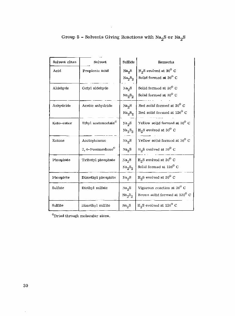
Group 5 - Solvents Giving Reactions with Na2S o r Na2S
...
Solvent class Solvent
Acid Propionic acid
~ .~ ~
Aldehyde Octyl aldehyde
~~
Anhydride Acetic anhydride
~ ~ _ _ ~ _ _ ~ .
Keto-ester Ethyl acetoacetate'
~ _._____ ~
Ketone Acetophenone
2,4-~entanedione~ ~
Sulfate Diethyl sulfate
Sulfite Dimethyl sulfite
Sulfide
Na2S
NazS2 . .
Na2S
Na2S2 ~
Na2S
Na2S2
Na2S
Na2S2
Na2S
Na2 S
Na2S
Na2S2
Na2S
Na2S
Na2S2
Na2S
Remarks
H2S evolved at 30' C
Solid formed at 30' C
Solid formed at 30' C
Solid formed at 30' C
Red solid formed at 30' C
Red solid formed at 120' C
Yellow solid formed at 30' C
H2S evolved at 30' C
Yellow solid formed at 30' C
-
-
~- _._
H2S evolved at 30' C ._ - ~ - -. -
H2S evolved at 30' C
Solid formed at 120' C
H2S evolved at 30' C
~-
Vigorous reaction at 30' C
Brown solid formed at 120'
H2S evolved at 120' C
'Dried through molecular sieve.
30
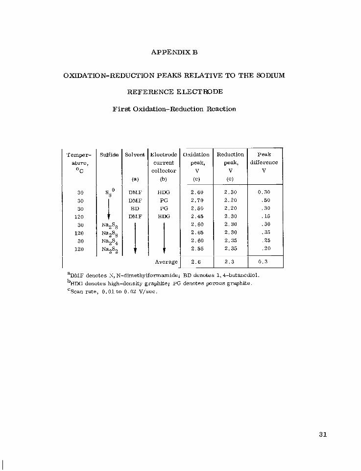
APPENDIX B
OXIDATION-REDUCTION PEAKS RELATIVE TO THE SODIUM
REFERENCEELECTmDE
First Oxidation-Reduction Reaction
T e m p e r -
a t u r e ,
OC
30
30 30
120
30 120
30
120
Sulfide
sao I Na2S8
N ~ ~ S ~
Na2S4 Na2S2
Solvent
(a)
DMF
DMF BD
DiV F
Zlectrode c u r r e n t
co l lec tor
(b)
HDG PG
P G HDG
1 - Average
2 . 6 0
2 . 7 0
2 . 5 0
2 . 4 5
2 . 6 0
2 . 6 5
2 . 6 0
2 . 5 5
2 . 6
2 . 3 0
2 . 2 0
2 . 2 0
2 . 3 0
2 . 3 0
2 . 3 0
2 . 3 5
2 . 3 5
P e a k
difference
v
0 .30
.50
. 3 0
.15
. 3 0
.35
. 2 5
. 2 0
2 . 3 I 0 . 3
%&IF deno tes S, N-dimethylformamide; BD deno tes 1 ,4-butanediol .
bHDG deno tes high-density graphi te ; PG denotes p o r o u s g r a p h i t e .
‘Scan rate, 0 . 0 1 t o 0 . 0 2 v/sec.
31

Second and Third Oxidation-Reduction Reactions
Solvent
(4 .
DMF
V
Electrode current
collector
(C )
HDG
PG
HDG
Average
Second oxidation
Peak, V
.
2 . 2
---
2 . 1
2 . 2
--- --- 2 . 3
--- 2 . 2
__-
2 . 2 ~- -
~~ -. .-
Third oxidation
Peak, V
__ ..
1 . 8 0
2.00
1 . 7 5
1.90
1 . 8 5
2.00
2.00
2 .05
1 .90
1 . 9
Third reduction
Peak, V
1 . 6 0
1 . 4 5
1 . 5 5
1 .60
1 . 6 0
1.65
1 . 6 5
1 .70
1 . 7 5
1 . 6 ~~
Third
difference, V
Peak
0.20
.55
.20
.30
.25
.35
.35
.35
.15
0 . 3 -~ Scan rate, 0.01 to 0.02 v/sec. C
dDMF denotes N, N-dimethylformamide.
32

I'
Reduction peak,
Fourth Oxidation-Reduction Reaction
Peak difference,
Temper- ature,
O C
~~
12 0
25
120
25 120 25 12 0
0 . 9
Sulfide
0.4
Solvent
(e)
---
1.0
DMF
DMF
DMF
DMA DMA DEA DEA
25
25
Electrode current
collector
(b)
HDG
HDG
HDG
PG P G Pt Pt
Average
Oxidation Peak, V
1.3
1.0 I ---
bHDG denotes high-density graphite; PG denotes porous graphite. eDMF denotes N, N-dimethylformamide; DMA denotes N, N-dimethylacetamide;
DEA denotes N, N-diethylacetamide.
Fifth Oxidation-Reduction Reaction
Electrode current
collector
(b)
HDG
HDG
P G
Reduction
---
fDMF denotes N, N-dimethylformamide; DMA denotes N, N-dimethylacetamide .
33

APPENDIX C
TAFEL EQUATION CALCULATIONS ASSUMING VARIOUS POSSIBLE MECHANISMS
First Reduction Reaction
The first reduction reaction (a cathodic process) is assumed to be
The discharging of three cells containing Sgo at 120° C gave an average Tafel slope of -0.39 (i. e. , -0.36, -0.31, -0.49). Calculations are made by assuming various suc- cessive chemical and electrochemical reactions (i. e. , a one- or two-electron transfer step). Assuming a one-electron'transfer step resulted in
The cathodic Tafel slope equations (refs. 7 and 8) for equations (1) and (2), with equa- tion (1) assumed to be the rate-determining step (RDS), a r e
-2.3 RT [K + (1 - p)(M)I-' F )
-
p = 1 -
where R, T, and F are the gas constant, temperature, and Faraday constant, re- spectively; K is the number of electrons that must be removed so that the products of the RDS can be transferred to the final product; P is the electron transfer coefficient; and M is the number of electrons involved in the rate-determining step. For equa- tions (1) and (2) (with eq. (1) as the RDS), M = l; K = 0; -2.3 RT/F at 120' C = -0.078; bc = -0.39; and
34

First Oxidation Reaction
The first oxidation reaction is assumed to be
The charging of a cell containing Na2S8 at 120' C gave a Tafel slope of 0.18. Assum- ing a one-electron transfer step resulted in
The anodic Tafel slope equations for equations (8) and (9), with equation (8) assumed to be the RDS, a re
b a = ( 2.3 RT )[N- L1-l
and
P = M 1 -
where L is the number of electrons removed to permit the RDS to occur once. For equations (8) and (9) (with eq. (8) as the RDS), M = 1; L = 0; ba = 0.18; and
35

I-) + d 1
P = = 0.4
Tafel Equation Calculations Assuming Various Mechanisms
The Tafel equation calculations a re summarized in the following table, along with those for the proposed oxidation-reduction mechanisms.
Assumed rate-determining
step (ms)
s80 + le- z (s8-)
Slope
-0.39 ~
-0.39
-0.39 - -0.39
~
-0.39 ~
-0.39
-0.39
0.18 ~
0.18 ~
0.18 ~
0.18
0.18 ~
0.18
0.18
Number of
Aectrons in ms,
M
1
Number of
electrons removed,
K
0
Number of
electrons removed,
L
--
Assumed mechanism Calculated electron transfer
coefficient, P
0.8
(a)
0.8
1.8
(a)
0.8
0.9
0.4
(a)
(a)
0 .4
0.4 ~
-0.6
0.2
Reaction
First r e duction
(eq. (C3))
2[s80 + le- z (s8-)] 2(Ss-) z S80 + s,=)
(sJ
S80 + s8= = 2(s8-)
s80 + le- z
(s8-) + le- z s8=
2 [(s8-) + le- = s8=]
s80 + 2e- 2 s8=
2k8= 2 (s8-) + le-]
2b;) z S80 + s8=
s8= + S80 z 2&)
2 [(s8-) z s80 + le-]
s8= 2 (s8-) + le-
ks-) = s80 + le-
s8= = s80 + 2e-
2(s83 = S80 + s8=
s80 + le- z (s8-)
(5)
First oxidation (es. (W) 2&) z S80 + s8=
s8= + S80 = 2 s ( s-> 0
0
1
1
-1
0
1
2
36

Assumed mechanism
sa= z 2(sq-)
2[s4= + sg= = 2s6=]
ss= = 2@;)
z[@) + s8= = @12-3)]
2 [(sc) + le- = s4=]
Z [ ( S ~ ~ - ~ ) + le- z s ~ ~ - ~ ]
z [ I ~ ~ ~ - ~ = 2s6=]
2[s,= = s6= + S2O]
2(s2-) z s4=
2 k 2 0 + le- = (Sz-)]
- - s4- + sg- z 2s6=
3s4= = s6= + 2s3=
2k3= z (sc) + le-]
2@) 2 s6=
2@;) z sg=
sg= + s4= z 2s6=
3s4= z Sl2-6
2 k4= = (s;) + le-]
s ~ ~ - ~ = (s12-5) + le-
( s ~ ~ - ~ ) = s ~ ~ - ~ + le-
Sl2-4 = 2s6=
~
#lope
~
0 . 2 9
0 . 2 9
~~
~
0 .29
0.29
~
~
0 .29 ~
0 .29 ~
0 . 2 9 ~
0 .29 ~
0 . 2 9 ~
0 .29 ~
0 .29 ~
0.15 ~
0.15
0.15 ~
0.15 ~
0.15 ~
0.15
0.15 ~
0.15
0.15
0.15 ~
Reaction
Second reduction
(C3))
Third oxidation
(C7))
Number of
electrons in ms,
M
0
Calculated electron transfer
coefficient, P
(a)
Number of
electrons removed,
K
0
Number of
Slectrons removed,
L
--
1 0 0.7
s4= + sa= z 2s6=
sg= z 2(5J
(sq-) + sg= = (s1,-3)
0 2 -- (a)
0 0 ~
0 0 --
( ~ ~ ~ - 3 ) + le- 2 s12+
Sl2-4 f 2s6=
sg= z s6= + s20
b-) 2(s2-) 2 s4=
~
sZo + le- z
s4= + sg= z 2s6=
3s4= z s6= + 2s3=
~
s3= z (s3-) + le-
2 (s3-) = s6=
+;) = sa=
sg= + s4= z 2s6=
3s4= = Sl2-6
s4= z (s4-) + le-
s12-6 z ( ~ ~ ~ - 5 ) + le-
( ~ ~ ~ - 5 ) = s12-4 + le-
Sl2-4 = 2s6=
1 0 0.7
0 2 -- (a)
0 0 -- (a)
1 0
~
2
0 .7
0 -- (a)
0 2 -- (a)
0 0
1 0
~
-2
0 . 5
0
1 0 0.5
0 -2
-2
0
1 0 0.5
1
0
-1 -0.5
-2
%determinate.
37

Assumed rate-determining
step (DS)
~~ -
ilope
0.15
0.15
0.15
0.15
0.15
0.15
0.15
0.15 -
0.19
Number of
slectrons in RDS,
M
0
1
0
0 _ _
2 .-
0
-.
0 . . ~~
2 __-
0 - ...
1
Calculated electron transfer
coefficient,
Reaction Assumed mechanism
s4= z 2(s2-) Third oxidation
continued (es. (C7))
s4= z 2(s2-)
2 ~ 2 0 + sq= z s;]
2 [(s2-) z s20 + le-] (s2-) z s20 + le-
s20 + s4= z ss=
3s4= z Sl2-6
- .
3s4= z Sl2-6
Sl2-4 z 2s6=
s12-6 z s ~ ~ - ~ + 2e-
Sl2-4 z 2s6=
3s4= z s6= + 2s3=
~~
3s4= z s6= + 2s3=
2s3= z s6= + 2e-
0.19 . __
0.19
0.19 -
0.19
1 s4= + le- z ( 5 ~ ~ )
( s ~ - ~ ) + le- z sqd4 -
s4-4 z 2s2=
s4= z s2= + s20
(47) 1 __
0
0.19 _-
0.19
0 s4= z sa= + s20
s20 + le- z (s2-) (s2-) + le- z sa=
0 ~~
0 ~
1 . .. .
0
2
1
0.19 1
2
0 ~. ~
0.19 s4= + 2e- z s ~ - ~
s4-4 z 2s2=
s4= + 2e- z s ~ - ~
s4-4 z 2s2= 0.19
%determinate.
38
REFERENCES
1 . K u " e r , J. T. ; and Weber , N. : Sodium/Sulfur Secondary Battery. SAE Paper 670179, Jan. 1967.
2. Rosen, Erik; and Tegman, m a r : A Preparative and X-Ray Diffraction Study of the Polysulfides Na2S2, Na2S4, and Na2S5. Acta Chem. Scand., vol. 25, no. 9, 1971, pp. 3329-3336.
3. Giggenbach, W . : On the Nature of the Blue Solutions of Sulfur. J. Inorg. Nucl. Chem., vol. 30, 1968, pp. 3189-3201.
4 . Brummer, S . B. ; et al. : Low Temperature Alkali Metal-Sulfur Batteries. COO-2520-3, Energy Research and Development A h . , 1976.
5 . Sawyer, Donald T . ; and Roberts, Julian L. : Experimental Electrochemistry for Chemists. John Wiley & Sons, Inc., 1974, p. 341.
6 . Sawyer, Donald T . ; and Roberts, Julian L. : Experimental Electrochemistry for Chemists. John Wiley & Sons, Inc., 1974, p. 61.
7 . Fraser, G. H . ; and Barradas, R. G. : A Simplified Calculation of Tafel Slopes for Successive Electrochemical Reactions. J. Electrochem. SOC. , vol. 112, no. 4, Apr. 1965, pp. 462-464.
8 . Del Duca, B . S . : Electrochemical Behavior of the Aluminum Electrode in Molten Salt Electrolytes. NASA TN D-5503, 1969.
9 . Merri t t , Margaret V. ; and Sawyer, Donald T. : Electrochemical Reduction of Elemental Sulfur in Aprotic Solvents. Inorg. Chem. , vol. 9, no. 2, Feb. 1970, pp. 211-215.
10. Martin, Robert P. ; et al: Further Studies of the Electrochemical Reduction of Sulfur in Aprotic Solvents. Inorg. Chem., vol. 12, no. 8, Aug. 1973, pp. 1921- 1925.
11. Kennedy, John H . ; and Adamo, Frank: Electrochemistry of Sulfur in LiCl-KCl Eutectic. J . Electrochem. Soc., vol. 119, no. 11, Nov. 1972, pp. 1518-1521.
12. Bonnaterre, R. ; and Cauquis, G. : Spectrophotometric Study of the Electro- chemical Reduction of Sulphur in Organic Media. J. Chem. Soc., Chem. Commun., no. 5, 1972, pp. 293-294.
13. Badoz-Lambling, Janine; et al. : La Reduction Du Soufre En Milieu Organique. Electrochim. Acta, vol. 21, 1976, pp. 119-131.
39

14. South, K . D.; Sudworth, J . L.; and Gibson, J . G . : Electrode Processes in Sodium Polysulfide Melts. J . Electrochem. Soc., wl. 119, May 1972, pp. 554-558.
15. Research on Electrodes and Electrolyte for the Ford Sodium-Sulfur Battery. Ford Motor Company, Contract Number NSF-C805, July 1974, pp. 103-124. (NSF/ RA/N-74-070, PB-235484/3. )
40

- - ~~ . ~~ 1 Z:-wernment Accession No.
_ _ ._
SOLUBILITY, STABILITY, AND ELECTROCHEMICAL STUDIES O F SULFUR-SULFIDE SOLUTIONS I N ORGANIC SOLVENTS
. - ..
William L. Fielder and Joseph Singer _. - - .. -
9. Performing Organization Name and Address
National Aeronautics and Space Administration Lewis Research Center Cleveland, Ohio 44135
National Aeronautics and Space Administration Washington, D. C. 20546
~ - - - -. ._ - - - - - 12 Sponsoring Agency Name and Address
~
. .
~~ . - . -. - -_ 15. Supplementary Notes
- 3. Recipient's Catalog No.
_ _ . . ~ ~ - ~ ~.
5. Report Date
A u g u s t 1978 ~~ . .
6. Performing Organization Code
. . .. -
8. Performing Organization Report No.
E-9552 10. Work Unit No
506- 23 11. Contract or Grant No.
~
13. Type of Report and Period Covered
Technical Pape r ~____.__ -
14. Sponsoring Agency Code
- - _ _ - - 16 Abstract
A preliminary study of the sulfur electrode in organic solvents suggests that the sys tem warranti further investigation for use in a low-temperature (100' to 120' C) Na-S secondary battery. A qualitative screening was undertaken at 120' C to determine the solubilities and stabilities of Na2S and Na2S2 in representatives of many classes of organic solvents. F rom this screening anc further quantitative studies, two c lasses of solvents were selected for further work: amides and cyclic polyalcohols. Voltammetric and Na-S cell charge-discharge studies of sulfide solutions i r organic solvents (e.g. , N, N-dimethylformamide) a t 120' C suggested that the reversibilities of the reactions on Pt or high-density graphite were moderately poor. However, the sulfur elec- trode was indeed reducible (and oxidizable) through the range of elemental sulfur to Na2S. Reac- tions and mechanisms a r e proposed for the oxidation-reduction processes occurring a t the sulfur electrode.
-- ~.~ - _ _ _ . - . - 17. Key Words (Suggested by Author(s)l
Electrochemical cells Soluble sulfur cell Polysulfide solubilities Polysulfide stabilities
19. Security Classif. (of this report1 20. Security Classif. (of this page1
Unclassified Unclassified - --
~ - ~ . ~ ~ - .
18. Distribution Statement
Unclassified - unlimited STAR Category 44
* For sale by the National Technical Information Service, Springfield, Virginia 22161
NASA-Langley, 1978

National Aeronautics and Space Administration
Washington, D.C. 20546 Official Business
Penalty for Private Use, $300
w n
THIRD-CLASS BULK RATE Postage and Fees Paid National Aeronautics and Space Administration NASA451
8 1 IU,E, 072178 SOO903DS DEPT OF T E E AIR FORCE AF REAPONS LABORATORY BTTN: TECHNICAL L I B R A R Y f S U L ) KIRTLBlD APB NM 8’7117
POSTMMTE~: If Undeliverable (Section 158 2 Postal Manual) Do Not
,
.
d