solution assignment #2 for computer networks · pdf file · 2017-03-03solution...
TRANSCRIPT
Solution _Assignment #2 for Computer Networks This assignment covers material from Unit 1, 2 and 3
1. OSI Layer working
2. Difference between TCP/IP and OSI (At least 6 points)
3. Details of all Protocols form all layers.
4. Working of each Networking devices
5. Working of networking commands with Syntax
6. Difference between a. TCP, UDP and SCTP , b. HTTP & SMTP c. HTTP &FTP d. HTTP 1.0 & HTTP1.1 e. Persistant &Non-Persistant f. FTP & TFTP g. IMAP &POP3 h. SMTP & FTP i. Connectionless & Connection-Oriented j. IPV4 & IPV6 k. Distance Vector & Link State Routing l. RIP & OSPF m. Classful & Classless(CIDR) Addressing n. Switch & Hub o. Switch & Bridge p. Switch & Router
7. Header Formats and diagram of following
a. HTTP request & response b. FTP c. SMTP d. MIME e. DHCP f. TELNET g. DNS h. TCP i. UDP & Pseudo UDP j. SCTP k. RTP l. TCP in wireless network m. RSVP n. Differentiated Services o. IPV4 p. IPV6 q. ARP & RARP r. RIP s. IP t. OSPF u. BGP
8. Prepare table for following:
1> IPV4 Classful addressing
2> IPV4 Private Address
9. Examples of all subnetting for Classful and Classless(CIDR) addressing
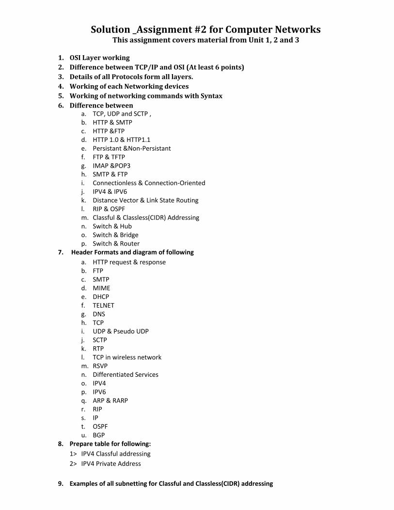
1. OSI Layer working
OSI Layer Name
Working of That Layer Protocols work on that Layer
N/W Devices work on that layer
Application The application layer is responsible for providing services to the user.
Resource sharing Provides a set of interfaces for sending and
receiving applications to gain access to and use network services
HTTP, HTTPS, SMTP , MIME, PoP3,IMAP,FTP, TFTP, DHCP, DNS, Telnet
Application Gateway
Presentation
This layer is also responsible for certain protocol conversions, data
encryption/decryption, or data compression/decompression. Manages data format, it converts data into a
generic format
Session Responsible for initiating, maintaining and terminating sessions
Responsible for security and access control to session information (via session participant identification)
Responsible for synchronization services, and for checkpoint services
Transport Manages the flow of data between parties by segmenting long data streams into smaller data chunks
Reliable transmission (Provides Acks of successful transmissions and requests
resends for packets which arrive with errors) Provides Congestion control and flow control Multiplexing and demultiplexing End-to-end data delivery
TCP,UDP,SCTP,RTP
Transport Gateway
Network Responsible for deciding how to route transmissions between computers Find best route to route the packet This layer also handles packet switching and network congestion control
IPV4,IPV6,IPSec,ARP,RARP,ICMP,OSPF,BGP,RIP,IGMP
Router
Data Link Handles special data frames (packets) between the Network layer and the Physical layer
Error control, Flow control,Framing
SLIP,PPP, Sliding window, Go back-n, Selective repeat
Switch, Bridge
Physical Converts bits into electronic signals & Viceversa This layer manages the interface between the
computer and the network medium
Hub, Repeater
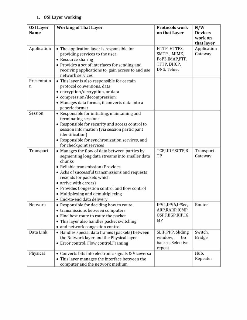
2. Difference between TCP/IP and OSI (At least 6 points)
Basis for Comparison
TCP/IP Model OSI Model
Expands To TCP/IP- Transmission Control Protocol/ Internet Protocol
OSI- Open system Interconnect
Meaning It is a client server model used for transmission of data over the internet.
It is a theoretical model which is used for computing system.
No. Of Layers 4 Layers 7 Layers Developed by Department of Defense (DoD) ISO (International Standard
Organization) Tangible Yes No Usage Mostly used Never used
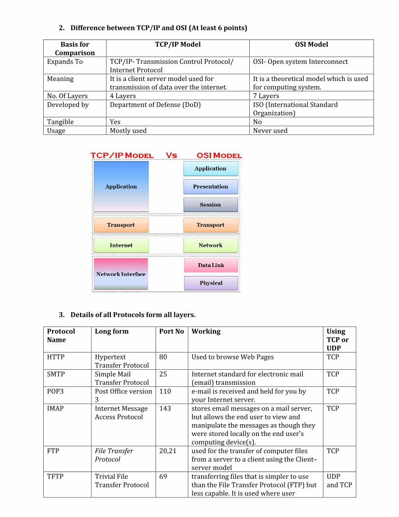
3. Details of all Protocols form all layers.
Protocol Name
Long form Port No Working Using TCP or UDP
HTTP Hypertext Transfer Protocol
80 Used to browse Web Pages TCP
SMTP Simple Mail Transfer Protocol
25 Internet standard for electronic mail (email) transmission
TCP
POP3 Post Office version 3
110 e-mail is received and held for you by your Internet server.
TCP
IMAP Internet Message Access Protocol
143 stores email messages on a mail server, but allows the end user to view and manipulate the messages as though they were stored locally on the end user's computing device(s).
TCP
FTP File Transfer Protocol
20,21 used for the transfer of computer files from a server to a client using the Client–server model
TCP
TFTP Trivial File Transfer Protocol
69 transferring files that is simpler to use than the File Transfer Protocol (FTP) but less capable. It is used where user
UDP and TCP
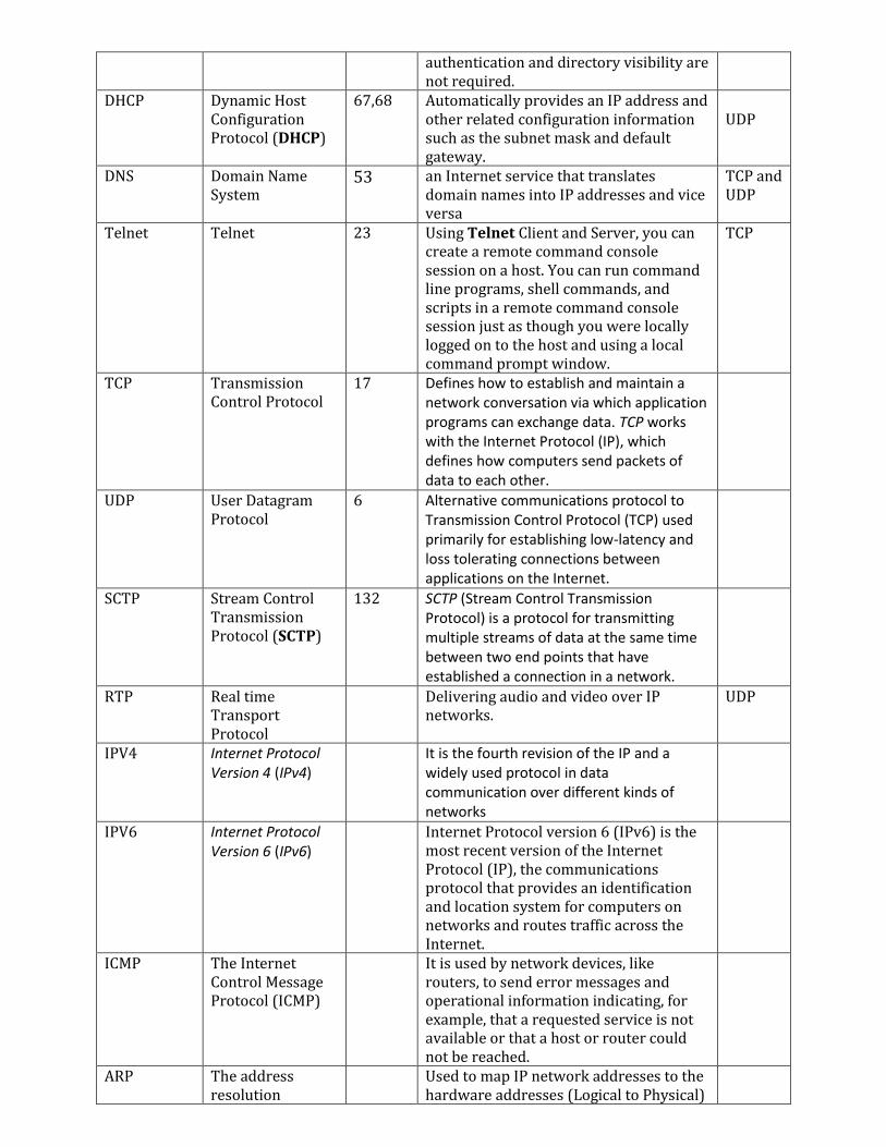
authentication and directory visibility are not required.
DHCP Dynamic Host Configuration Protocol (DHCP)
67,68 Automatically provides an IP address and other related configuration information such as the subnet mask and default gateway.
UDP
DNS Domain Name System
53
an Internet service that translates domain names into IP addresses and vice versa
TCP and UDP
Telnet Telnet 23 Using Telnet Client and Server, you can create a remote command console session on a host. You can run command line programs, shell commands, and scripts in a remote command console session just as though you were locally logged on to the host and using a local command prompt window.
TCP
TCP Transmission Control Protocol
17 Defines how to establish and maintain a network conversation via which application programs can exchange data. TCP works with the Internet Protocol (IP), which defines how computers send packets of data to each other.
UDP User Datagram Protocol
6 Alternative communications protocol to Transmission Control Protocol (TCP) used primarily for establishing low-latency and loss tolerating connections between applications on the Internet.
SCTP Stream Control Transmission Protocol (SCTP)
132 SCTP (Stream Control Transmission Protocol) is a protocol for transmitting multiple streams of data at the same time between two end points that have established a connection in a network.
RTP Real time Transport Protocol
Delivering audio and video over IP networks.
UDP
IPV4 Internet Protocol Version 4 (IPv4)
It is the fourth revision of the IP and a widely used protocol in data communication over different kinds of networks
IPV6 Internet Protocol Version 6 (IPv6)
Internet Protocol version 6 (IPv6) is the most recent version of the Internet Protocol (IP), the communications protocol that provides an identification and location system for computers on networks and routes traffic across the Internet.
ICMP The Internet Control Message Protocol (ICMP)
It is used by network devices, like routers, to send error messages and operational information indicating, for example, that a requested service is not available or that a host or router could not be reached.
ARP The address resolution
Used to map IP network addresses to the hardware addresses (Logical to Physical)
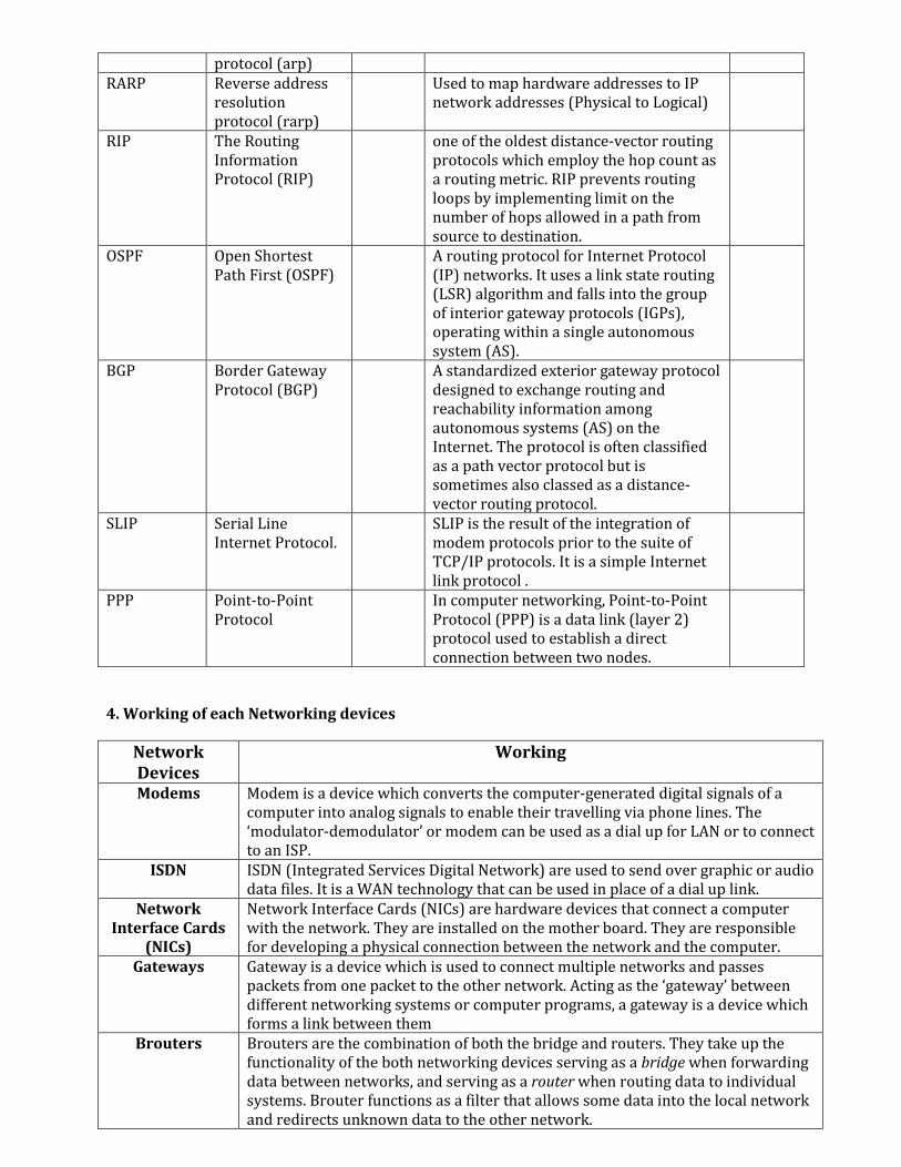
protocol (arp) RARP Reverse address
resolution protocol (rarp)
Used to map hardware addresses to IP network addresses (Physical to Logical)
RIP The Routing Information Protocol (RIP)
one of the oldest distance-vector routing protocols which employ the hop count as a routing metric. RIP prevents routing loops by implementing limit on the number of hops allowed in a path from source to destination.
OSPF Open Shortest Path First (OSPF)
A routing protocol for Internet Protocol (IP) networks. It uses a link state routing (LSR) algorithm and falls into the group of interior gateway protocols (IGPs), operating within a single autonomous system (AS).
BGP Border Gateway Protocol (BGP)
A standardized exterior gateway protocol designed to exchange routing and reachability information among autonomous systems (AS) on the Internet. The protocol is often classified as a path vector protocol but is sometimes also classed as a distance-vector routing protocol.
SLIP Serial Line Internet Protocol.
SLIP is the result of the integration of modem protocols prior to the suite of TCP/IP protocols. It is a simple Internet link protocol .
PPP Point-to-Point Protocol
In computer networking, Point-to-Point Protocol (PPP) is a data link (layer 2) protocol used to establish a direct connection between two nodes.
4. Working of each Networking devices
Network Devices
Working
Modems
Modem is a device which converts the computer-generated digital signals of a computer into analog signals to enable their travelling via phone lines. The ‘modulator-demodulator’ or modem can be used as a dial up for LAN or to connect to an ISP.
ISDN ISDN (Integrated Services Digital Network) are used to send over graphic or audio data files. It is a WAN technology that can be used in place of a dial up link.
Network Interface Cards
(NICs)
Network Interface Cards (NICs) are hardware devices that connect a computer with the network. They are installed on the mother board. They are responsible for developing a physical connection between the network and the computer.
Gateways
Gateway is a device which is used to connect multiple networks and passes packets from one packet to the other network. Acting as the ‘gateway’ between different networking systems or computer programs, a gateway is a device which forms a link between them
Brouters
Brouters are the combination of both the bridge and routers. They take up the functionality of the both networking devices serving as a bridge when forwarding data between networks, and serving as a router when routing data to individual systems. Brouter functions as a filter that allows some data into the local network and redirects unknown data to the other network.
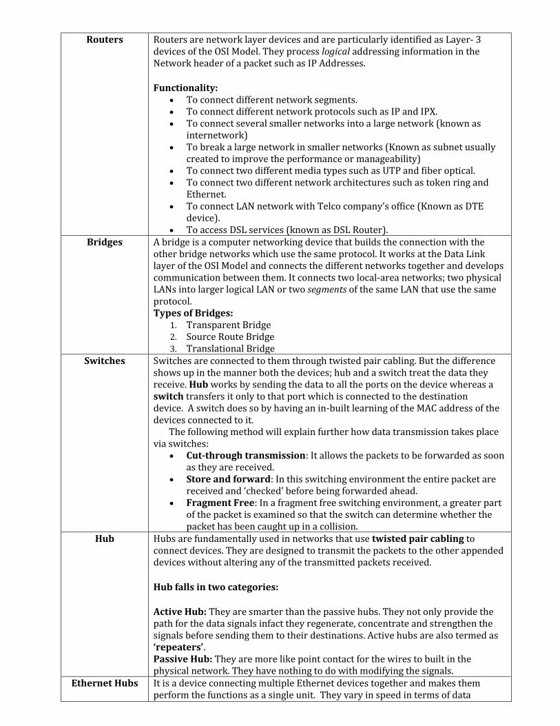
Routers Routers are network layer devices and are particularly identified as Layer- 3 devices of the OSI Model. They process logical addressing information in the Network header of a packet such as IP Addresses.
Functionality: To connect different network segments. To connect different network protocols such as IP and IPX. To connect several smaller networks into a large network (known as
internetwork) To break a large network in smaller networks (Known as subnet usually
created to improve the performance or manageability) To connect two different media types such as UTP and fiber optical. To connect two different network architectures such as token ring and
Ethernet. To connect LAN network with Telco company’s office (Known as DTE
device). To access DSL services (known as DSL Router).
Bridges A bridge is a computer networking device that builds the connection with the other bridge networks which use the same protocol. It works at the Data Link layer of the OSI Model and connects the different networks together and develops communication between them. It connects two local-area networks; two physical LANs into larger logical LAN or two segments of the same LAN that use the same protocol. Types of Bridges:
1. Transparent Bridge 2. Source Route Bridge 3. Translational Bridge
Switches Switches are connected to them through twisted pair cabling. But the difference shows up in the manner both the devices; hub and a switch treat the data they receive. Hub works by sending the data to all the ports on the device whereas a switch transfers it only to that port which is connected to the destination device. A switch does so by having an in-built learning of the MAC address of the devices connected to it. The following method will explain further how data transmission takes place via switches:
Cut-through transmission: It allows the packets to be forwarded as soon as they are received.
Store and forward: In this switching environment the entire packet are received and ‘checked’ before being forwarded ahead.
Fragment Free: In a fragment free switching environment, a greater part of the packet is examined so that the switch can determine whether the packet has been caught up in a collision.
Hub Hubs are fundamentally used in networks that use twisted pair cabling to connect devices. They are designed to transmit the packets to the other appended devices without altering any of the transmitted packets received.
Hub falls in two categories:
Active Hub: They are smarter than the passive hubs. They not only provide the path for the data signals infact they regenerate, concentrate and strengthen the signals before sending them to their destinations. Active hubs are also termed as ‘repeaters’. Passive Hub: They are more like point contact for the wires to built in the physical network. They have nothing to do with modifying the signals.
Ethernet Hubs It is a device connecting multiple Ethernet devices together and makes them perform the functions as a single unit. They vary in speed in terms of data
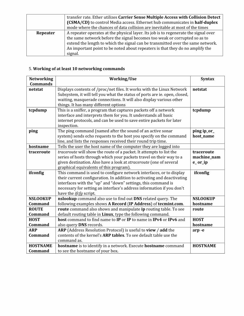
transfer rate. Ether utilizes Carrier Sense Multiple Access with Collision Detect (CSMA/CD) to control Media access. Ethernet hub communicates in half-duplex mode where the chances of data collision are inevitable at most of the times
Repeater A repeater operates at the physical layer. Its job is to regenerate the signal over the same network before the signal becomes too weak or corrupted so as to extend the length to which the signal can be transmitted over the same network. An important point to be noted about repeaters is that they do no amplify the signal.
5. Working of at least 10 networking commands
Networking Commands
Working/Use Syntax
netstat
Displays contents of /proc/net files. It works with the Linux Network Subsystem, it will tell you what the status of ports are ie. open, closed, waiting, masquerade connections. It will also display various other things. It has many different options
netstat
tcpdump
This is a sniffer, a program that captures packets off a network interface and interprets them for you. It understands all basic internet protocols, and can be used to save entire packets for later inspection.
tcpdump
ping
The ping command (named after the sound of an active sonar system) sends echo requests to the host you specify on the command line, and lists the responses received their round trip time.
ping ip_or_ host_name
hostname Tells the user the host name of the computer they are logged into traceroute
traceroute will show the route of a packet. It attempts to list the series of hosts through which your packets travel on their way to a given destination. Also have a look at xtraceroute (one of several graphical equivalents of this program).
traceroute machine_name_ or_ip
ifconfig
This command is used to configure network interfaces, or to display their current configuration. In addition to activating and deactivating interfaces with the “up” and “down” settings, this command is necessary for setting an interface's address information if you don't have the ifcfg script.
ifconfig
NSLOOKUP Command
nslookup command also use to find out DNS related query. The following examples shows A Record (IP Address) of tecmint.com.
NSLOOKUP hostname
ROUTE Command
route command also shows and manipulate ip routing table. To see default routing table in Linux, type the following command.
route
HOST Command
host command to find name to IP or IP to name in IPv4 or IPv6 and also query DNS records.
HOST hostname
ARP Command
ARP (Address Resolution Protocol) is useful to view / add the contents of the kernel’s ARP tables. To see default table use the command as.
arp -e
HOSTNAME Command
hostname is to identify in a network. Execute hostname command to see the hostname of your box.
HOSTNAME
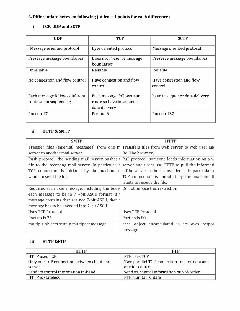
6. Differentiate between following (at least 4 points for each difference)
i. TCP, UDP and SCTP
UDP TCP SCTP
Message oriented protocol Byte oriented protocol Message oriented protocol
Preserve message boundaries Does not Preserve message
boundaries
Preserve message boundaries
Unreliable Reliable Reliable
No congestion and flow control Have congestion and flow
control
Have congestion and flow
control
Each message follows different
route so no sequencing
Each message follows same
route so have in sequence
data delivery
have in sequence data delivery
Port no 17 Port no 6 Port no 132
ii. HTTP & SMTP
SMTP HTTP
Transfer files (eg;email messages) from one mail
server to another mail server
Transfers files from web server to web user agent
(ie. The browser)
Push protocol: the sending mail server pushes the
file to the receiving mail server. In particular, the
TCP connection is initiated by the machine that
wants to send the file.
Pull protocol: someone loads information on a web
server and users use HTTP to pull the information
offthe server at their convenience. In particular, the
TCP connection is initiated by the machine that
wants to receive the file.
Requires each user message, including the body of
each message to be in 7 –bit ASCII format. If the
message contains that are not 7-bit ASCII, then the
message has to be encoded into 7-bit ASCII
Do not impose this restriction
Uses TCP Protocol Uses TCP Protocol
Port no is 25 Port no is 80
multiple objects sent in multipart message each object encapsulated in its own response
message
iii. HTTP &FTP
HTTP FTP HTTP uses TCP FTP uses TCP Only one TCP connection between client and server
Two parallel TCP connection, one for data and one for control
Send its control information in-band Send its control information out-of-order HTTP is stateless FTP maintains State

iv. Persistent & Non-Persistent (HTTP 1.0/1.1)
Persistent Non-Persistent Uses HTTP/1.0 Uses HTTP/1.1 Have only 16 status codes Have introduced new 24 status code Provides only basic authentication Provides strong authentication Uses Non persistent connection Uses Persistent connection RTT is more so bandwidth waste is vast RTT is less so bandwidth utilization is good Stateless Uses cookies as state management mechanism Supports only GET POST and HEAD method Supports GET, POST, HEAD,PUT and DELETE
v. FTP & TFTP
Basis for Comparison
FTP TFTP
Abbreviation File Transfer Protocol. Trivial File Transfer Protocol. Authentication Authentication is required in FTP for
communication between client and server.
No authentication is required in TFTP.
Service FTP uses TCP service which is a connection-oriented service.
TFTP uses UDP service which is connection-less service.
Software FTP software is larger than TFTP. TFTP software is smaller than FTP and fits into readonly memory of the diskless workstation.
Connection FTP establishes two connections one for data(TCP port no. 21) and one for control(TCP port no. 20).
TFTP establishes a single connection for its file transfer (UDP port no. 69).
Commands/Message
FTP have many commands. TFTP have only five messages.
Complexity FTP is more complex TFTP is less complex.
vi. IMAP &POP3
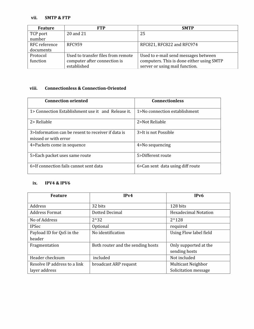
vii. SMTP & FTP
viii. Connectionless & Connection-Oriented
Connection oriented Connectionless
1> Connection Establishment use it and Release it. 1>No connection establishment
2> Reliable 2>Not Reliable
3>Information can be resent to receiver if data is
missed or with error
3>It is not Possible
4>Packets come in sequence 4>No sequencing
5>Each packet uses same route 5>Different route
6>If connection fails cannot sent data 6>Can sent data using diff route
ix. IPV4 & IPV6
Feature IPv4 IPv6
Address 32 bits 128 bits
Address Format Dotted Decimal Hexadecimal Notation
No of Address 2^32 2^128
IPSec Optional required
Payload ID for QoS in the
header
No identification Using Flow label field
Fragmentation Both router and the sending hosts Only supported at the
sending hosts
Header checksum included Not included
Resolve IP address to a link
layer address
broadcast ARP request Multicast Neighbor
Solicitation message
Feature FTP SMTP TCP port number
20 and 21 25
RFC reference documents
RFC959 RFC821, RFC822 and RFC974
Protocol function
Used to transfer files from remote computer after connection is established
Used to e-mail send messages between computers. This is done either using SMTP server or using mail function.

x. Distance Vector & Link State Routing (RIP & OSPF)
Distance Vector Routing (RIP) Link State Routing (OSPF)
Used in small networks Used in larger networks
It has a limited number of hops (only 16) It has unlimited number of hops
High convergence time Convergence time is low.
Periodically advertise updates Only new changes in a network.
It has loop problem No loop problem
Updates are broadcasted Updates are multicasted
Advertises only the directly connected
routers and full routing tables,
Advertise the updates, and flood the
advertisement.
Eg. RIP ,IGRP , BGP . Eg. : OSPF , IS-IS
xi. Classful & Classless(CIDR) Addressing
Classful Addressing
Classless(CIDR) Addressing
Classful addressing divides an IP address into the Network and Host portions along octet boundaries; this portion is fixed for each class.
Classless addressing uses a variable number of bits for the network and host portions of the address.
In the classful addressing system all the IP addresses that are available are divided into the five classes A,B,C,D and E.
In the classless addressing IP addresses are not divided into classes.
Each of the IP address belongs to a particular class that's why they are classful addresses
Classless addressing treats the IP address as a 32 bit stream of ones and zeroes, where the boundary between network and host portions can fall anywhere between bit 0 and bit 31.
Address of 192.168.0.0 indicates it is Class C address and 24 bits are from N/W side and 8 bits are from Client side.
CIDR address of 192.168.0.0/29 defines a 29bits are from network side and remaining 3 bits are from client side
xii. Switch & Hub
Basis for Comparison Hub Switch Layer Physical layer. Layer 1 devices Data Link Layer. Layer 2
Function To connect a network of personal computers together, they can be joined through a central hub.
Allow to connect multiple device and port can be manage, Vlan can create security also can apply
Data Transmission form
Electrical signal or bits Frame (L2 Switch) Frame & Packet (L3 switch)
Ports 4/12 ports Switch is multi port Bridge. 24/48 ports Device Type Passive Device (Without Software) Active Device (With Software) &
Networking device Used in (LAN, MAN, WAN) LAN LAN Transmission Mode Half duplex Half/Full duplex Broadcast Domain Hub has one Broadcast Domain. Switch has one broadcast domain
Definition An electronic device that connects many network device together so that devices can exchange data
A network switch is a computer networking device that is used to connect many devices together on a computer network. A switch is considered more advanced than a hub because a switch will on send msg to
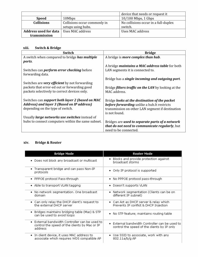
xiii. Switch & Bridge
Switch Bridge A switch when compared to bridge has multiple ports.
Switches can perform error checking before forwarding data.
Switches are very efficient by not forwarding packets that error-ed out or forwarding good packets selectively to correct devices only.
Switches can support both layer 2 (based on MAC Address) and layer 3 (Based on IP address) depending on the type of switch.
Usually large networks use switches instead of hubs to connect computers within the same subnet.
A bridge is more complex than hub.
A bridge maintains a MAC address table for both LAN segments it is connected to.
Bridge has a single incoming and outgoing port.
Bridge filters traffic on the LAN by looking at the MAC address.
Bridge looks at the destination of the packet before forwarding unlike a hub.It restricts transmission on other LAN segment if destination is not found.
Bridges are used to separate parts of a network that do not need to communicate regularly, but need to be connected.
xiv. Bridge & Router
device that needs or request it Speed 10Mbps 10/100 Mbps, 1 Gbps
Collisions Collisions occur commonly in setups using hubs.
No collisions occur in a full-duplex switch.
Address used for data tramsmission
Uses MAC address Uses MAC address
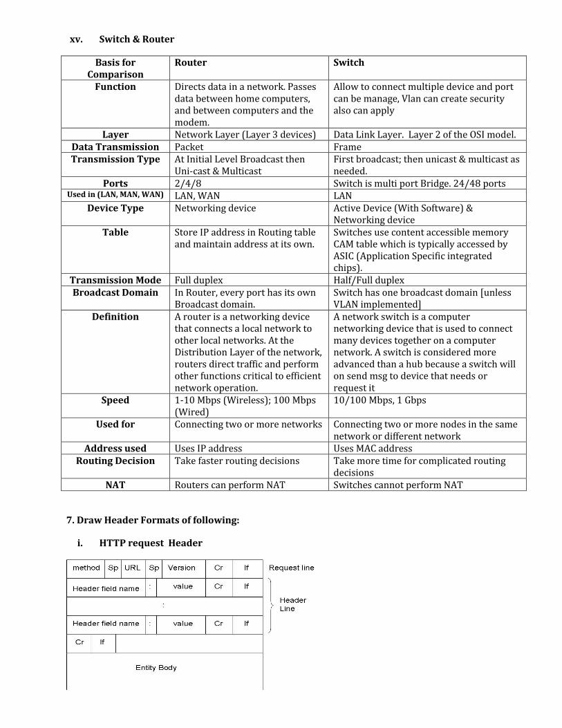
xv. Switch & Router
Basis for Comparison
Router Switch
Function Directs data in a network. Passes data between home computers, and between computers and the modem.
Allow to connect multiple device and port can be manage, Vlan can create security also can apply
Layer Network Layer (Layer 3 devices) Data Link Layer. Layer 2 of the OSI model. Data Transmission Packet Frame Transmission Type At Initial Level Broadcast then
Uni-cast & Multicast First broadcast; then unicast & multicast as needed.
Ports 2/4/8 Switch is multi port Bridge. 24/48 ports Used in (LAN, MAN, WAN) LAN, WAN LAN
Device Type Networking device Active Device (With Software) & Networking device
Table Store IP address in Routing table and maintain address at its own.
Switches use content accessible memory CAM table which is typically accessed by ASIC (Application Specific integrated chips).
Transmission Mode Full duplex Half/Full duplex Broadcast Domain In Router, every port has its own
Broadcast domain. Switch has one broadcast domain [unless VLAN implemented]
Definition A router is a networking device that connects a local network to other local networks. At the Distribution Layer of the network, routers direct traffic and perform other functions critical to efficient network operation.
A network switch is a computer networking device that is used to connect many devices together on a computer network. A switch is considered more advanced than a hub because a switch will on send msg to device that needs or request it
Speed 1-10 Mbps (Wireless); 100 Mbps (Wired)
10/100 Mbps, 1 Gbps
Used for Connecting two or more networks Connecting two or more nodes in the same network or different network
Address used Uses IP address Uses MAC address Routing Decision Take faster routing decisions Take more time for complicated routing
decisions NAT Routers can perform NAT Switches cannot perform NAT
7. Draw Header Formats of following:
i. HTTP request Header
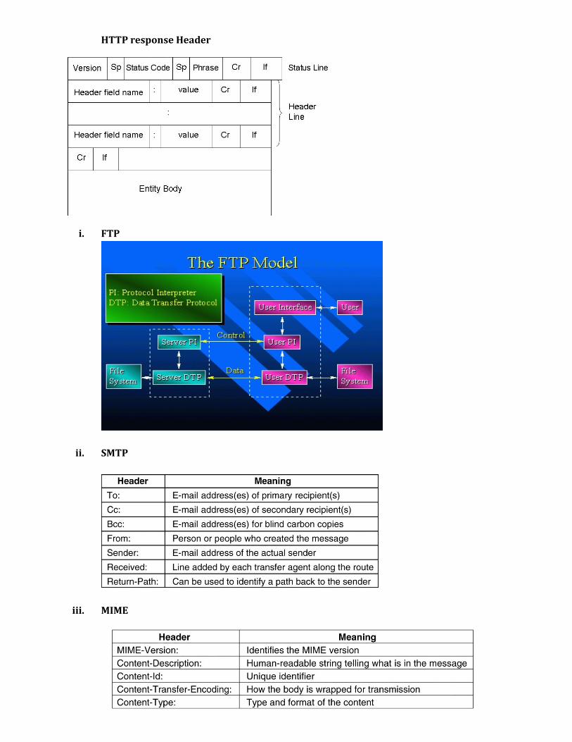
HTTP response Header
i. FTP
ii. SMTP
iii. MIME
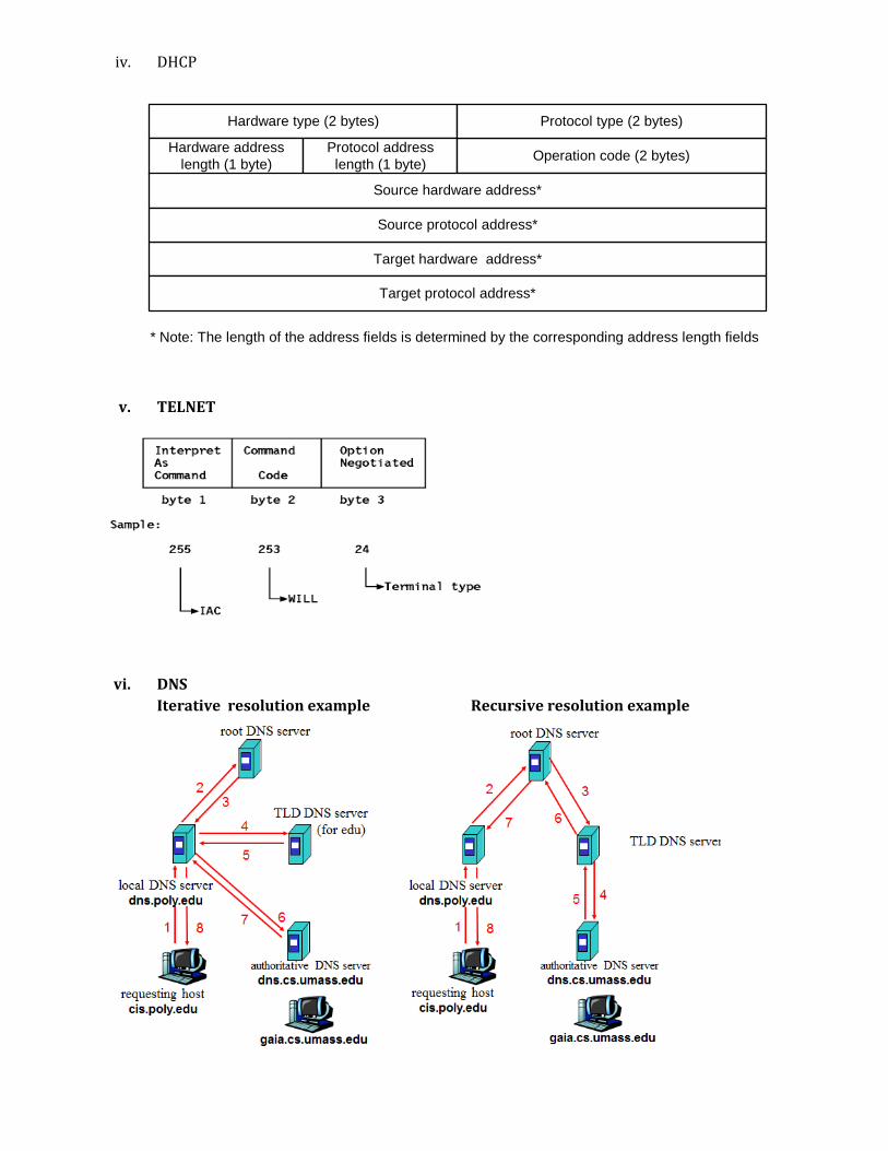
iv. DHCP
v. TELNET
vi. DNS
Iterative resolution example Recursive resolution example
Hardware type (2 bytes)
Hardware address
length (1 byte)
Protocol address
length (1 byte)Operation code (2 bytes)
Target hardware address*
Protocol type (2 bytes)
Source hardware address*
Source protocol address*
Target protocol address*
* Note: The length of the address fields is determined by the corresponding address length fields
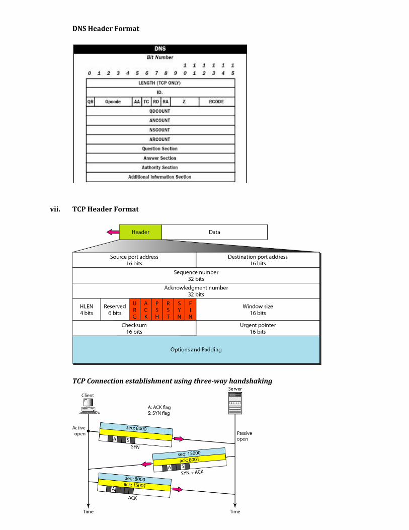
DNS Header Format
vii. TCP Header Format
TCP Connection establishment using three-way handshaking

TCP Connection Establishment Scenario (3)
Three protocol scenarios for establishing a connection using a three-way handshake.
(a) Normal operation, (b) Old CONNECTION REQUEST appearing out of nowhere.
(c) Duplicate CONNECTION REQUEST and duplicate ACK.
TCP Connection Release- The two-army problem
TCP Connection termination using three-way handshaking
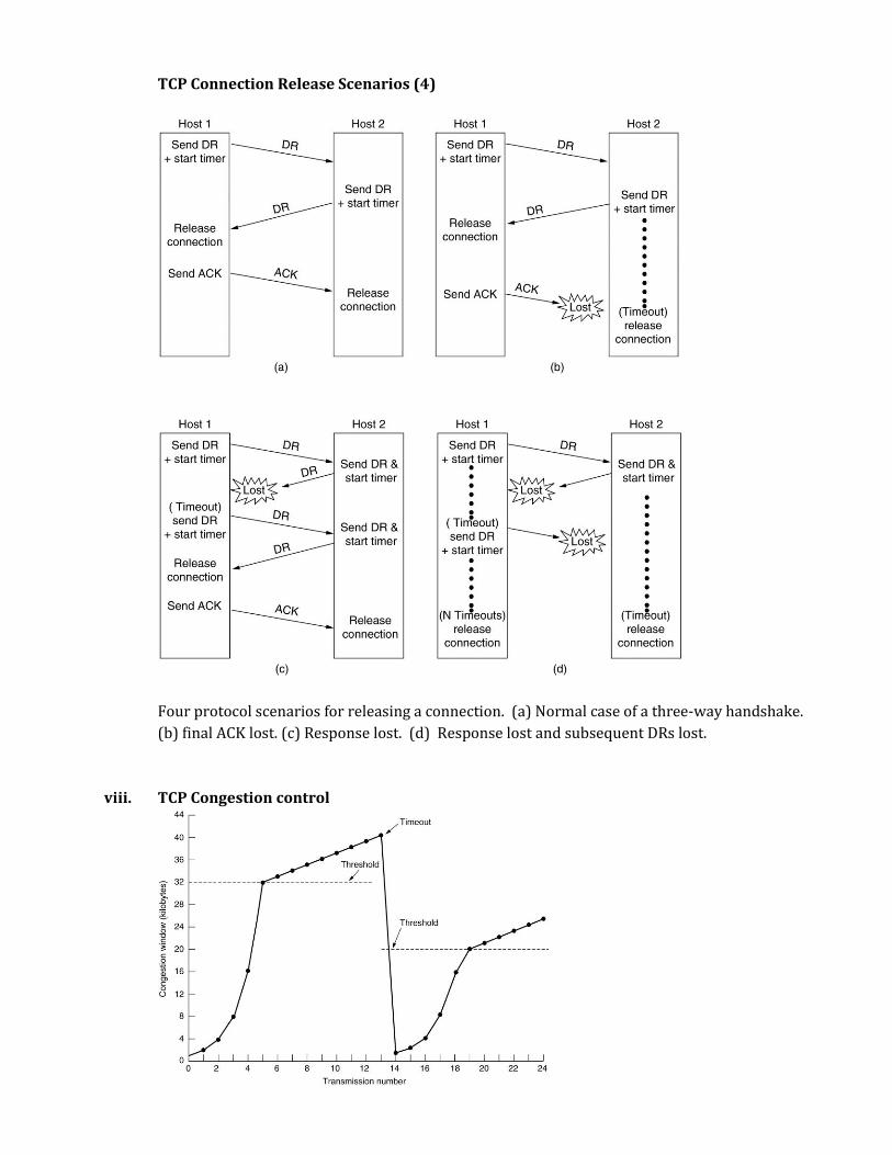
TCP Connection Release Scenarios (4)
Four protocol scenarios for releasing a connection. (a) Normal case of a three-way handshake.
(b) final ACK lost. (c) Response lost. (d) Response lost and subsequent DRs lost.
viii. TCP Congestion control
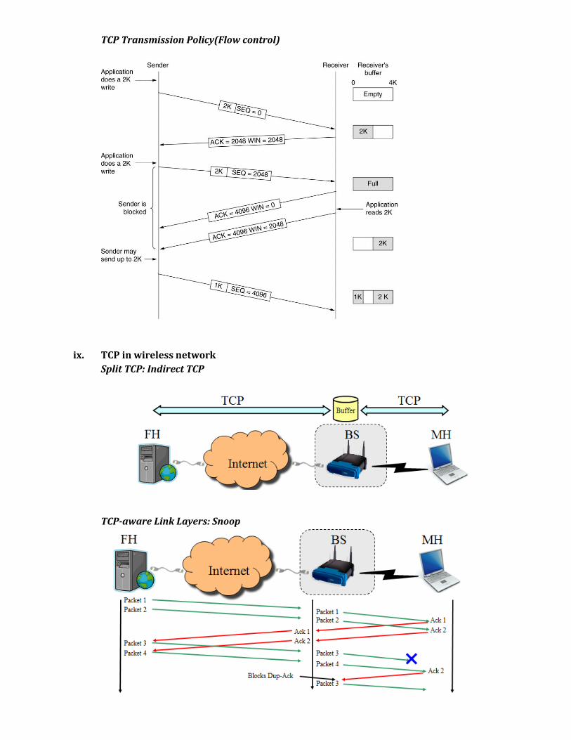
TCP Transmission Policy(Flow control)
ix. TCP in wireless network
Split TCP: Indirect TCP
TCP-aware Link Layers: Snoop
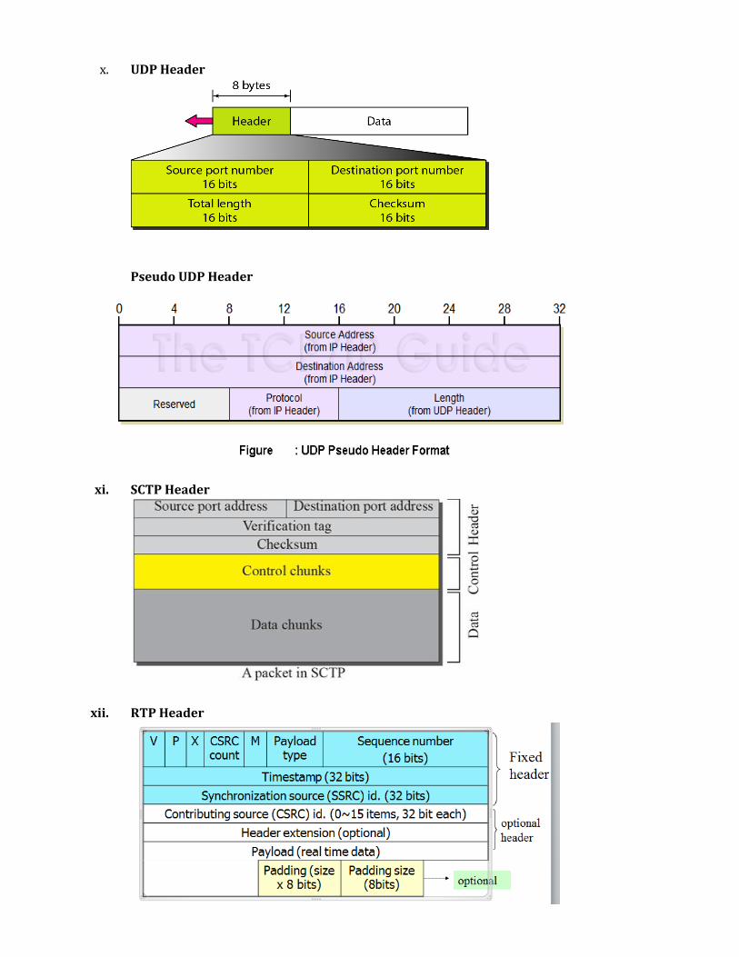
x. UDP Header
Pseudo UDP Header
xi. SCTP Header
xii. RTP Header
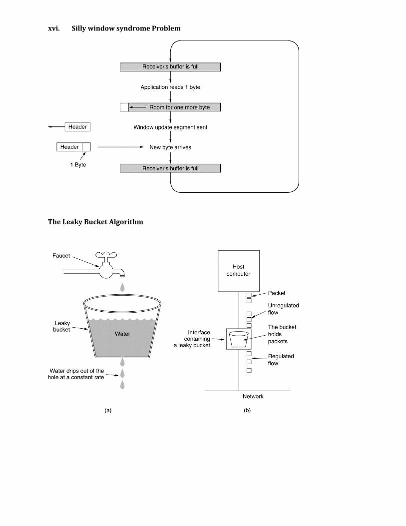
xvi. Silly window syndrome Problem
The Leaky Bucket Algorithm
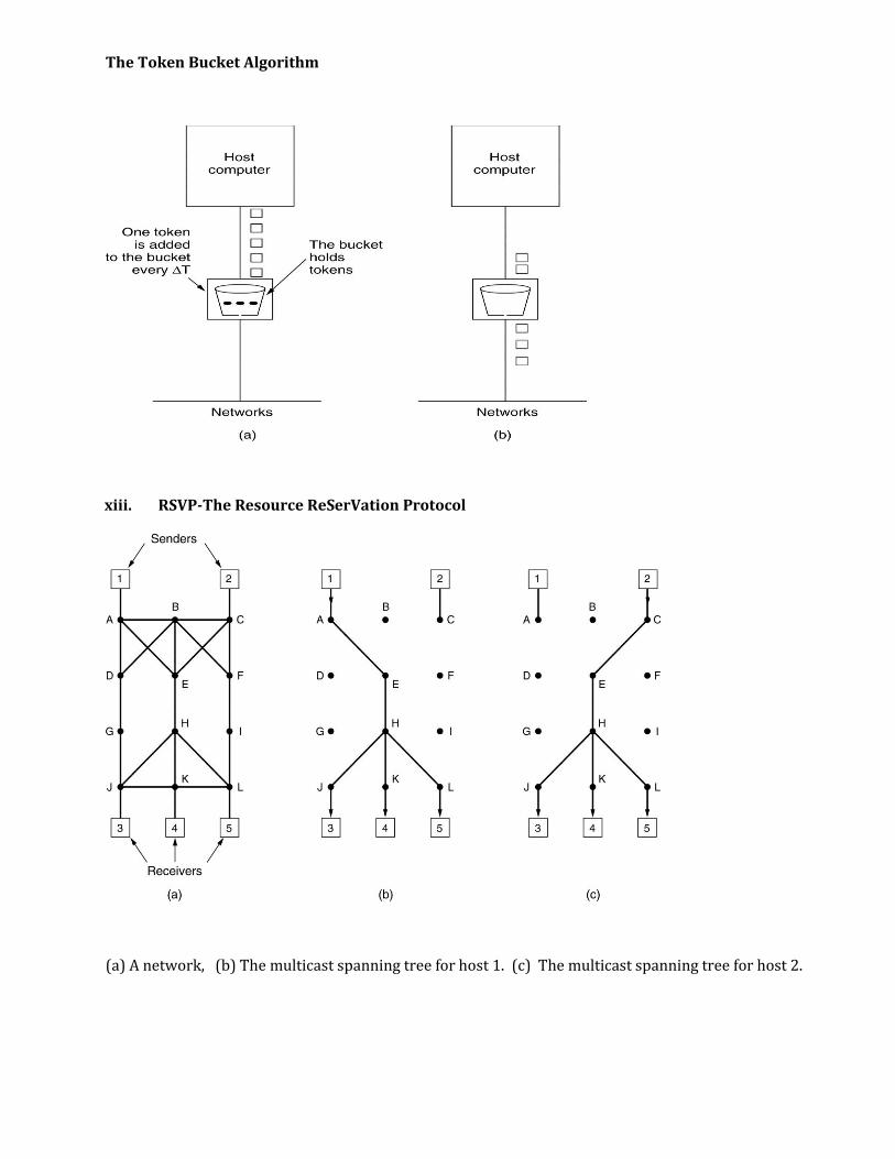
The Token Bucket Algorithm
xiii. RSVP-The Resource ReSerVation Protocol
(a) A network, (b) The multicast spanning tree for host 1. (c) The multicast spanning tree for host 2.
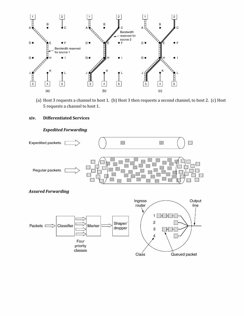
(a) Host 3 requests a channel to host 1. (b) Host 3 then requests a second channel, to host 2. (c) Host
5 requests a channel to host 1.
xiv. Differentiated Services
Expedited Forwarding
Assured Forwarding
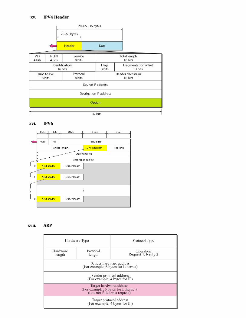
xv. IPV4 Header
xvi. IPV6
xvii. ARP
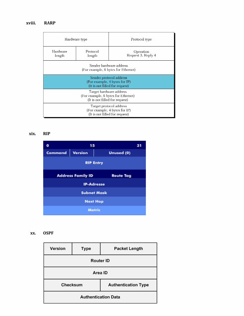
xviii. RARP
xix. RIP
xx. OSPF

xxi. BGP
8. Prepare table for following:
1> IPV4 Classful addressing
Name of Class
Range Binary Representation
No of Network bits
No of Host (client)bits
Default Mask
A 1-127 0 8 24 255.0.0.0 B 128-191 10 16 16 255.255.0.0 C 192-223 110 24 8 255.255.255.0 D 224-239 1110 Used for Multicasting - E 240-255 1111 Reserved for Scientific &
Research purpose -
2> IPV4 Private Address
Class Address Block A 10.0.0.0 1 B 172.16 TO 172.31 16 C 192.168.0 TO 192.168.255 256
9. Examples of all subnetting for Classful and Classless(CIDR) addressing, taken in classrooms.
a) Divide the network 220.125.5.192/26 into 8 sub networks. How many hosts can be connected in
each network? Show their IP range, network address and broadcast address. [6]
ANS:
No of addresses for whole network are N= 232-26 =26 =64
First Address in network is- 220.125.2.192/26
Last address in network is- 220.125.5.255/26
As 8 subnet has to design so we divide no of address with no of sub networks
i.e. 64/8= 8. That means each network has 8 addresses.
New subnet mask will be:
For 8 network 3 bits are required (log2 8 =3) to add to /26 mask, so new mask
will be 26+3=29.
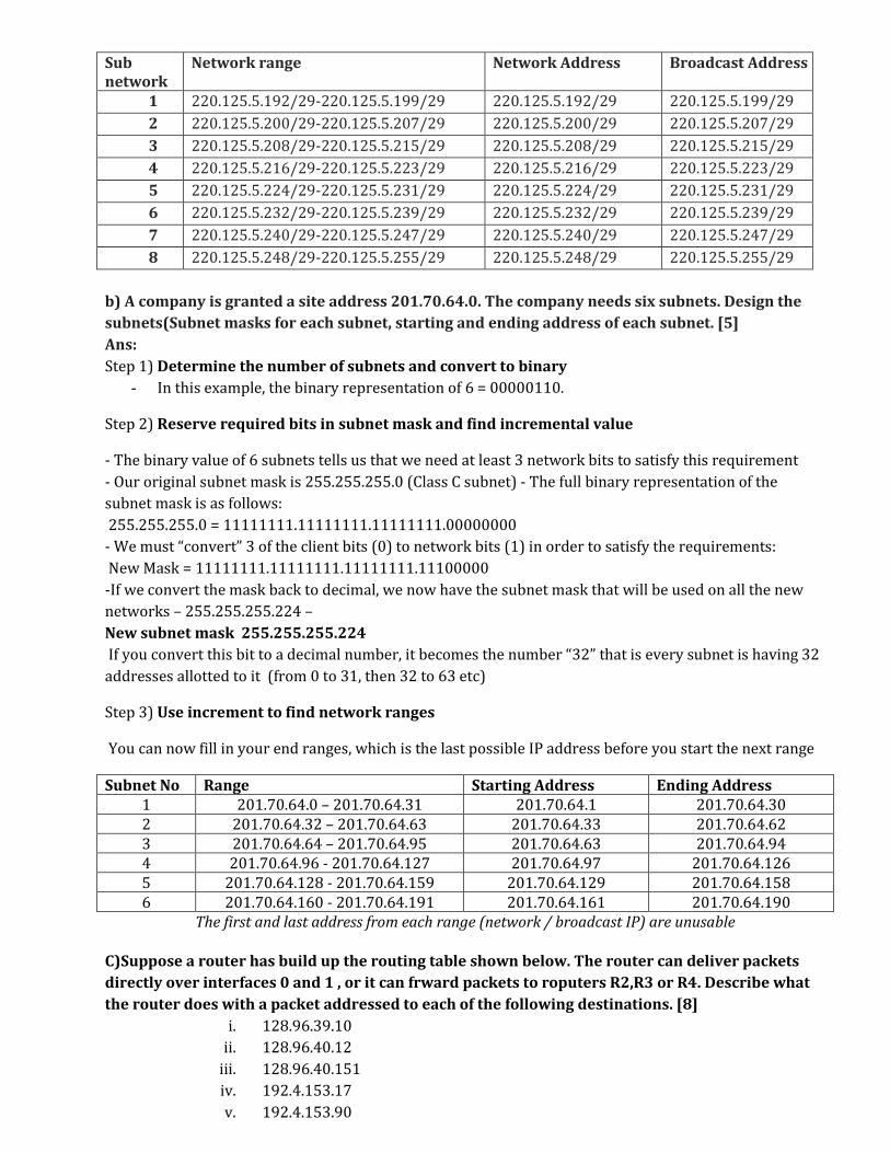
Sub network
Network range Network Address Broadcast Address
1 220.125.5.192/29-220.125.5.199/29 220.125.5.192/29 220.125.5.199/29
2 220.125.5.200/29-220.125.5.207/29 220.125.5.200/29 220.125.5.207/29
3 220.125.5.208/29-220.125.5.215/29 220.125.5.208/29 220.125.5.215/29
4 220.125.5.216/29-220.125.5.223/29 220.125.5.216/29 220.125.5.223/29
5 220.125.5.224/29-220.125.5.231/29 220.125.5.224/29 220.125.5.231/29
6 220.125.5.232/29-220.125.5.239/29 220.125.5.232/29 220.125.5.239/29
7 220.125.5.240/29-220.125.5.247/29 220.125.5.240/29 220.125.5.247/29
8 220.125.5.248/29-220.125.5.255/29 220.125.5.248/29 220.125.5.255/29
b) A company is granted a site address 201.70.64.0. The company needs six subnets. Design the
subnets(Subnet masks for each subnet, starting and ending address of each subnet. [5]
Ans:
Step 1) Determine the number of subnets and convert to binary
- In this example, the binary representation of 6 = 00000110.
Step 2) Reserve required bits in subnet mask and find incremental value
- The binary value of 6 subnets tells us that we need at least 3 network bits to satisfy this requirement
- Our original subnet mask is 255.255.255.0 (Class C subnet) - The full binary representation of the
subnet mask is as follows:
255.255.255.0 = 11111111.11111111.11111111.00000000
- We must “convert” 3 of the client bits (0) to network bits (1) in order to satisfy the requirements:
New Mask = 11111111.11111111.11111111.11100000
-If we convert the mask back to decimal, we now have the subnet mask that will be used on all the new
networks – 255.255.255.224 –
New subnet mask 255.255.255.224
If you convert this bit to a decimal number, it becomes the number “32” that is every subnet is having 32
addresses allotted to it (from 0 to 31, then 32 to 63 etc)
Step 3) Use increment to find network ranges
You can now fill in your end ranges, which is the last possible IP address before you start the next range
Subnet No Range Starting Address Ending Address 1 201.70.64.0 – 201.70.64.31 201.70.64.1 201.70.64.30 2 201.70.64.32 – 201.70.64.63 201.70.64.33 201.70.64.62 3 201.70.64.64 – 201.70.64.95 201.70.64.63 201.70.64.94 4 201.70.64.96 - 201.70.64.127 201.70.64.97 201.70.64.126 5 201.70.64.128 - 201.70.64.159 201.70.64.129 201.70.64.158 6 201.70.64.160 - 201.70.64.191 201.70.64.161 201.70.64.190
The first and last address from each range (network / broadcast IP) are unusable
C)Suppose a router has build up the routing table shown below. The router can deliver packets
directly over interfaces 0 and 1 , or it can frward packets to roputers R2,R3 or R4. Describe what
the router does with a packet addressed to each of the following destinations. [8]
i. 128.96.39.10
ii. 128.96.40.12
iii. 128.96.40.151
iv. 192.4.153.17
v. 192.4.153.90
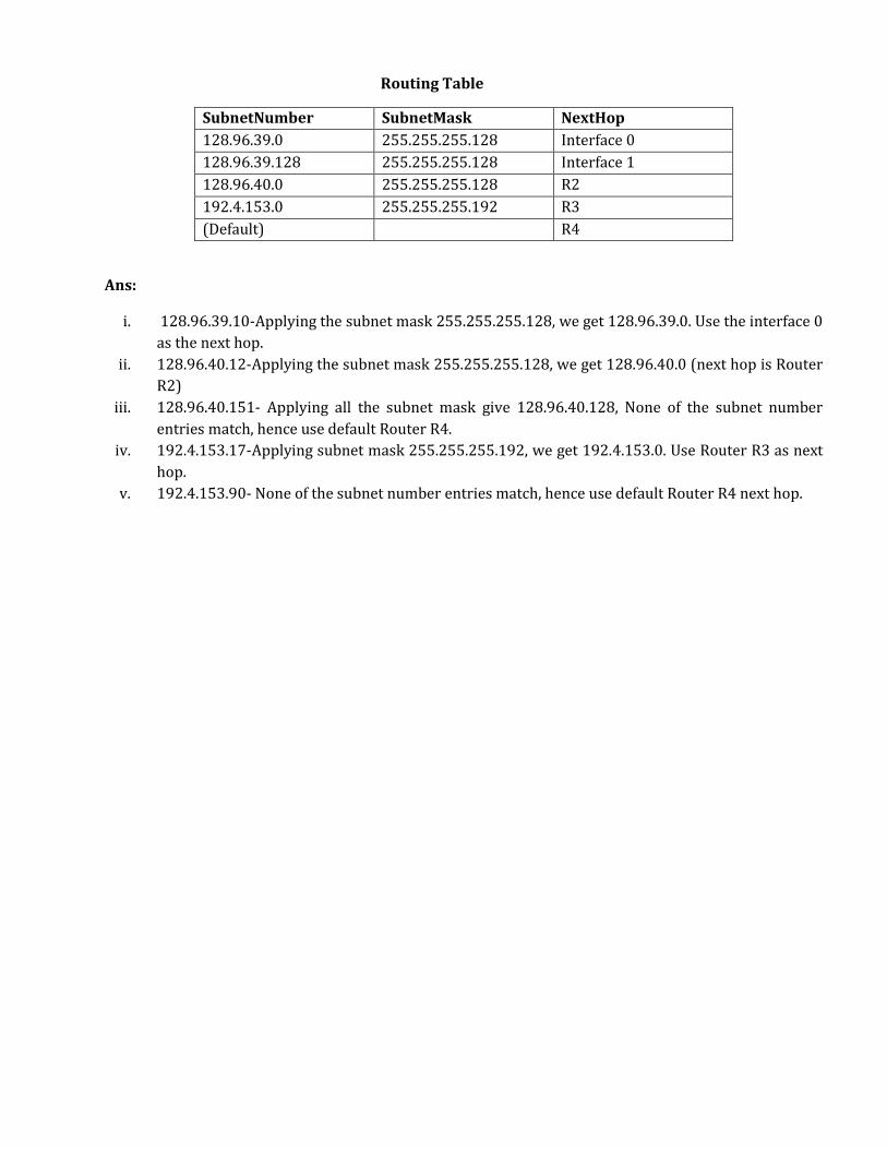
Routing Table
Ans:
i. 128.96.39.10-Applying the subnet mask 255.255.255.128, we get 128.96.39.0. Use the interface 0
as the next hop.
ii. 128.96.40.12-Applying the subnet mask 255.255.255.128, we get 128.96.40.0 (next hop is Router
R2)
iii. 128.96.40.151- Applying all the subnet mask give 128.96.40.128, None of the subnet number
entries match, hence use default Router R4.
iv. 192.4.153.17-Applying subnet mask 255.255.255.192, we get 192.4.153.0. Use Router R3 as next
hop.
v. 192.4.153.90- None of the subnet number entries match, hence use default Router R4 next hop.
SubnetNumber SubnetMask NextHop
128.96.39.0 255.255.255.128 Interface 0
128.96.39.128 255.255.255.128 Interface 1
128.96.40.0 255.255.255.128 R2
192.4.153.0 255.255.255.192 R3
(Default) R4