solution of tutorial 5 - isolated dc-dc converters … of...elec4614 power electronics solution to...
TRANSCRIPT

ELEC4614 Power Electronics
Solution to Tutorial 5 – Isolated DC-DC 1 F. Rahman Converters and Inverters
University of New South Wales School of Electrical Engineering & Telecommunications
Solution to Tutorial 5 – Isolated DC-DC Converters & Inverters 1.
The maximum value of mL which will ensure discontinuous conduction (i.e. complete
demagnetisation) is given by
22
1m
S 2
N( 1 D )L R
2 f N
For a higher value of Lm, iLmin > 0 and conduction in Lm is continuous.
(i) O 2
d 1
V N D 3 D
V N 1 D 2 1 D
2 2
O O
24 Dor 1.5 D 0.615
10 1 D
V V120 R 4.8
R 120
(ii) 22
m 3
( 1 0.615 ) 2L 4.8 1.58 H
32 100 10
(iii) O
O S S
V D D0.01 C 128 F
V RCf Rf 0.01
dV
OVR
Di
1V 2V
T
ELEC4614 Power Electronics
Solution to Tutorial 5 – Isolated DC-DC 2 F. Rahman Converters and Inverters
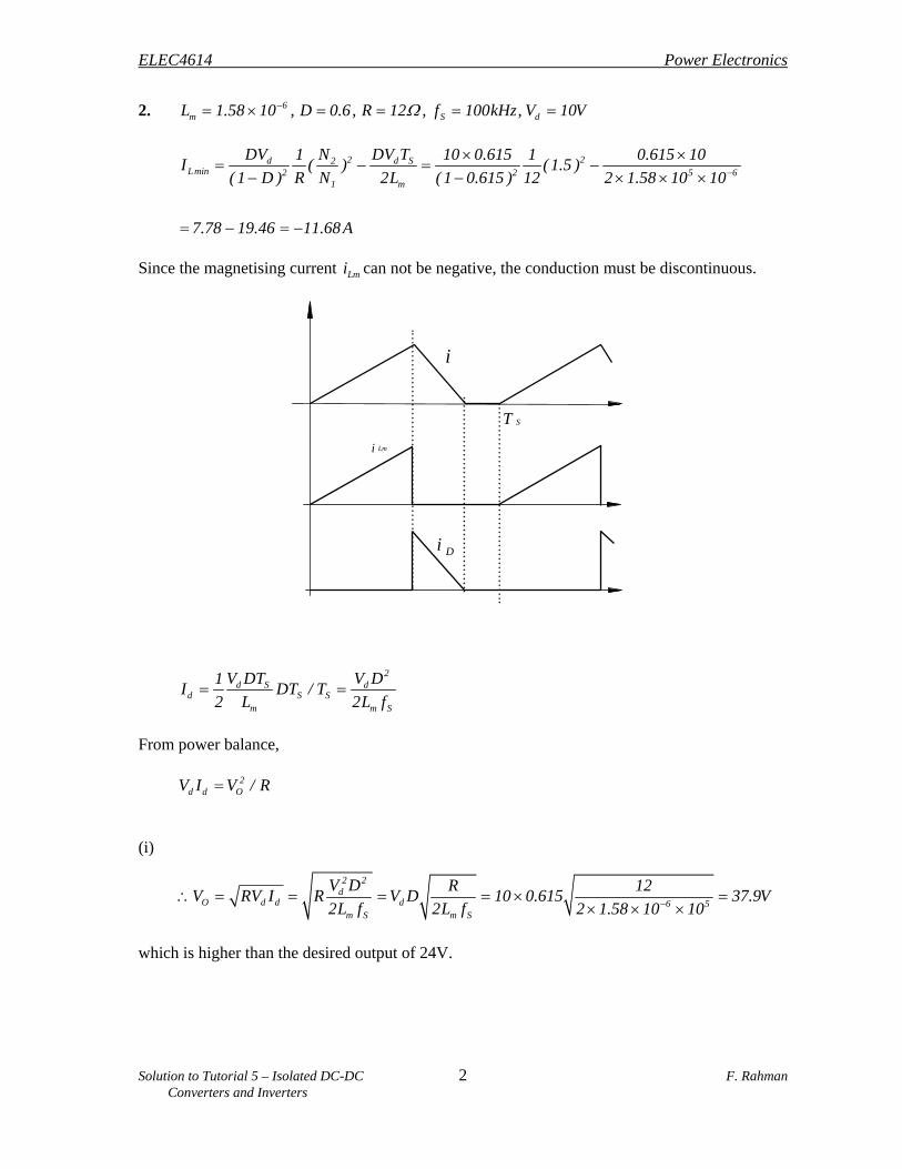
2. 6
m S dL 1.58 10 , D 0.6, R 12 , f 100kHz, V 10V
2 2d d S2Lmin 2 2 5 6
1 m
DV DV TN1 10 0.615 1 0.615 10I ( ) ( 1.5 )
( 1 D ) R N 2L ( 1 0.615 ) 12 2 1.58 10 10
7.78 19.46 11.68 A
Since the magnetising current Lmi can not be negative, the conduction must be discontinuous.
2
d S dd S S
m m S
V DT V D1I DT / T
2 L 2L f
From power balance, 2
d d OV I V / R
(i)
2 2
dO d d d 6 5
m S m S
V D R 12V RV I R V D 10 0.615 37.9V
2L f 2L f 2 1.58 10 10
which is higher than the desired output of 24V.
ST
i
Lmi
Di

ELEC4614 Power Electronics
Solution to Tutorial 5 – Isolated DC-DC 3 F. Rahman Converters and Inverters
(ii) When Vo is restored to 24V
2 2
oo
V 24P 48W
R 12
d d dP V I 48W
2
dd
d m s
V48I 4.8 A
V 2L f
6 34.8 2 1.58 10 100 10
D 0.38910
(iii) 2
O ,new
24P 48W
12
3. Since 3 1N N , max3
1
1D 0.5
N1
N
(i) dV 43.2 52.8V
2O
1 d min max
N 1V 0.232
N V D
For Vd = 43.2 V
2
1
N 50.232
N 43.2 0.5
If this turns ratio is selected and Vd becomes 52.8 V, then
o
2d
1
V 5D 0.408
52.8 0.232NV
N
which is lower than Dmax = 0.5.
For Vd = 52.8 V
2
1
N 50.189
N 52.8 0.5
This should be 2.42 not 4.8
Answer should be 0.427

ELEC4614 Power Electronics
Solution to Tutorial 5 – Isolated DC-DC 4 F. Rahman Converters and Inverters
When this turns ratio is selected and Vd becomes 43.2 V,
o
2d
1
V 5D 0.612
43.2 0.189NV
N
which is higher than Dmax = 0.5.
Therefore, we must select the smallest turns ratio N2/N1 = 0.232. Note that since only 0.2, and 0.25 are the nearest possible turn ratios, the above calculations must be repeated for these available turns ratios, to select the correct one. We will ignore this practical aspect in the following calculations.
(ii) 2O O min Lmin
1
N 150.232 P 15W I I 3A
N 5
To operate the converter in the continuous conduction mode, L mini 0. To ensure continuous conduction
we should choose the lower output power, i.e., Po = 15 W. At the boundary of continuous/discontinuous conduction:
LL min L
ii I 0
2
2d O
o1S O min
min min s
N(V V )
V 1 DN1DT I 3
2 L 2L f
A
When Vd = 43.2, and N2/N1 = 0.232, 5
D 0.543.2 0.232
min s
5 1 0.53
2L f
. Hence, minL 4.16 H
When dV 52.8 V 5
D 0.40952.8 0.232
minL 4.93 H .
We must choose Lmin = 4.94 H because L = 4.16 mH will make iL discontinuous when Vd = 52.5V.
(iii) 3max
1 max
N 1D 0.7 , 1 0.429
N D
1T ,max d d d
3
NV V V 3.33V
N

ELEC4614 Power Electronics
Solution to Tutorial 5 – Isolated DC-DC 5 F. Rahman Converters and Inverters

ELEC4614 Power Electronics
Solution to Tutorial 5 – Isolated DC-DC 6 F. Rahman Converters and Inverters
4.
(i) 2O d
1
N 1V V D 48 0.4 12.8V
N 1.5
L O
12.8I I 1.28 A
10
(ii) O SL 3
V ( 1 D )T 12.8 ( 1 0.4 )i 0.55A
L 0.4 10 35000
L,max L,min
0.55 0.55i 1.28 1.56 A, i 1.28 1.01A
2 2
(iii) O O2 3 2 6
( 1 D ) 12.8 ( 1 0.4 )V V 19.6mV
8LCf 8 0.4 10 100 F ( 35 ) 10
(iv) The primary current is the sum of the magnetising current and the reflected current from
the secondary. The peak magnetising current:
d SL,max 3
m
V DT 48 0.4i 0.11A
L 5 10 35000
2p ,max L,max Lm,max
1
N 1i i i 1.56 0.11 1.15A
N 1.5
(v) Time taken by the magnetising current to fall to zero is given by:
31 S
1
N 0.4t DT 1 11.4 s
N 35000
Also, SDT 11.4 sec
Lmi reaches zero 11.4 11.4 22.8 s into each switching period.
Since ST 28.57 s , the transformer resets in each cycle.

ELEC4614 Power Electronics
Solution to Tutorial 5 – Isolated DC-DC 7 F. Rahman Converters and Inverters
t = 0
Vd
5. The output voltage waveform vo is
By taking the t = 0 reference in the middle of the positive pulse as indicated, since f ( ) f ( ) ,
2
2dn d
0 0
d
4V1a V cos n t d t cos n t d t
4V nsin
n 2
Note that, = . The output voltage vo is given by
do
n 1,3,5,......
4V nv sin cos n t
n 2
(i) 1V rms value of the fundamental = d4V
2
V3 = rms value of the 3rd harmonic = d4V
3 2
V5 = rms value of the 5th harmonic = d4V
5 2
.
.
. and so on
(ii) For the required fundamental rms voltage is 240 V,

ELEC4614 Power Electronics
Solution to Tutorial 5 – Isolated DC-DC 8 F. Rahman Converters and Inverters
d1
4VV 240
2 V
d240 2
V 266.4V4
(iii) Expressions for the load current waveform can be obtained in three ways. Method 1:
1d1
1
4V Li cos t tan
Z R
1d3
3
4V 3 Li cos 3 t tan
3 Z R
1d5
5
4V 5 Li cos 5 t tan
3 Z R
. . .
and so on, where 22nz R n L
o 1 3 5i i i i
The number of harmonics to be included in the above sum is determined by the significance of the relative contribution of the highest harmonic term.
Method 2:
Solution for the load current io in closed form is obtained by finding the steady-state maximum and minimum values of the load current. Using the closed-form solution covered in lecture
1
1
Rt
L
1 min Rt
L
V 1 eI I
R1 e
where t1 = 10 msec, the ON-time for T1 and T2 for 50 Hz output.
Given: R = 9 , L = 9/314 = 0.0287 H
9
9
1 min 9
9
266.4 1 eI I 27.13A
91 e
Imax = 27.13 A

ELEC4614 Power Electronics
Solution to Tutorial 5 – Isolated DC-DC 9 F. Rahman Converters and Inverters
Vd = 266.4 V
- Vd = 266.4 V
27.13 A
27.13 A
Vd = 266.4 V
For 0 < t < 0.01 sec
R
td d L
V Vi 27.13 e
R R
For 0.01 < t <0.02 sec
R
td d L
V Vi 27.13 e
R R
Method 3: The solution of the differential equation of the load current can be carried out for each half cycle, starting from t = 0 sec, with the initial value for the load current assumed to be zero. At the end of each half cycle, the value of current becomes the initial current into the next half cycle which is a better estimate. The solution is repeated for subsequent half cycles until it is found that imax is equal to imin, albeit for its sign. This iterative process is very easily implemented on a computer. (iv)
012
o0
n n n
n 1,3,5,...
1P i Rdt ................( 1)
0.01
V I cos .........( 2 )

ELEC4614 Power Electronics
Solution to Tutorial 5 – Isolated DC-DC 10 F. Rahman Converters and Inverters
31.19 A
31.19 A
+ 380 V
380 V
90 90
2.552.5 52.5 2.5 2.5msec
380 V
380 V180 360
where
1n nn n n
22
4V V n LV ; I ; tan
R2 n R n L
6.
(i). d1
4V n 4 380V sin 342.34
2n 2 2
V (rms)
1
1
Rt
Ld
min Rt
L
V 1 eI
R1 e
where t1 = 0.01 sec.
= 31.19 A
For 0 < t < 0.01 sec
Rt
d d Lo min
314t
V Vi I e
R R
38 69.9e A
(ii) Quasi- square-wave output:
d1rms
4V 90V sin
22
= 242 V
The expression for the load current io is obtained from
di
L Ri Vdt
2.5 < t < 7.5 msec By taking t1 = 0 at t = 2.5 msec,

ELEC4614 Power Electronics
Solution to Tutorial 5 – Isolated DC-DC 11 F. Rahman Converters and Inverters
1314toi 38 38e
1314t 314 0.005oi 38 38e 38 38e 30.09 A
Note that current during first 2.5 msec is zero. 7.5 < t < 12.5 msec Current falls exponentially while freewheeling locally through a diode and a switch. By taking time t2 = 0 at t = 7.5 msec,
2314toi 30.09e A
At t = 12.5 msec, 2314t 319 0.005oi 30.09e 30.09e 6.26 A
12.5 < t < 17.5 msec Load current io rises negatively when –380 V applies across the load. By taking t3 = 0 at t = 12.5 msec,
3314toi 38 38 6.26 e A
At t = 17.5 msec, 3314t 314 0.005oi 38 38 6.26 e 38 38 6.26 e 28.79 A
17.5 < t < 22.5 msec Currents falls exponentially, while freewheeling through a diode and a switch. By taking time t4 = 0 at t = 17.5 msec,
4314toi 28.79e A
oi at 22.5 msec is 314 0.005o22.5i 28.79e 5.99 A
22.5 < t < 27.5 msec
5314 toi 38 38 5.99 e A
314 0.005o27.5i 38 38 5.99 e 28.84 A
27.5 < t < 32.5 msec
6314toi 28.84e
ELEC4614 Power Electronics
Solution to Tutorial 5 – Isolated DC-DC 12 F. Rahman Converters and Inverters
314 0.005o32.5i 28.84e 6 A

ELEC4614 Power Electronics
Solution to Tutorial 5 – Isolated DC-DC 13 F. Rahman Converters and Inverters
32.5 < t < 37.5 msec
7314 toi 38 38 6 e 28.84
314 0.005o37.5i 38 38 6 e 28.84 A
which is the same as at 27.5 msec. The output current settles after this time.
(iii) o1 01maxV V cos2
Vo1max occurs for the square-wave output when = 0, i.e., = 180.
Thus, do1max
4VV 342.34
2 V
o1V 200 342.34 cos
2
108.5
(iv) = 108.5, = 180 - = 180 – 108.5 = 71.6.
d3
4V 3V sin 108.98
23 2
V; d5
4V 5V sin 1.49
25 2
V
T1 T4
T2 T3
Vd
Vd
0 2

ELEC4614 Power Electronics
Solution to Tutorial 5 – Isolated DC-DC 14 F. Rahman Converters and Inverters
7. The waveform has quarter-wave symmetry.
By taking t = 0 at the center of the positive pulse,
0
2 d d2n d
0
4V 4V4 na V cos n t d t sin n t sin
n n 2
for n = 1, 3, 5, …… When the center of the pulse is displaced from the t = 0 axis by an arbitrary angle ‘’ as shown below, the symmetry conditions do not apply and, ordinarily, we have to find both an and bn coefficients of the Fourier series representing the waveform. The foregoing result for an can still be used without finding bn explicitly.
Note that the harmonics of the quasi-square waveform will be displaced by angle n and that their amplitudes remain unchanged. The harmonic can be represented by their phasors in terms of their rms value and phase angle n. Thus
dn
d
4V nV sin n
2n 2
4V nsin cos n j sin n
2n 2
Vd
Vd
2
t = 0t
/2-/2
Fundamental
Vd
Vd
2
t = 0
t

ELEC4614 Power Electronics
Solution to Tutorial 5 – Isolated DC-DC 15 F. Rahman Converters and Inverters
1 2
P1 P2 P3
t = 0
0
Vd
-Vd
The instantaneous values of the harmonics are given by
dn
4V nv sin cos n t
n 2
and do
1,3,5,.....
4V nv sin cos n t
n 2
For the PWM waveform given below
The voltage pulses P1 and P3 are of the same width. The switching angle 1 and 2 define the widths of all three voltage pulses in each half cycle. The t = 0 reference is assumed at the center of pulse P2. Thus
For pulse P1: 1 1 ; displacement from the reference = 1
2 2
leading
d 1 1nP1
d 1 1 1
4V nV sin n
2 2 2n
4V nsin cos n j sin n
2 2 2 2 2n 2
For pulse P2: 2 22 ; displacement from reference = 0
2d
nP2
n 24VV sin 0
2n 2
=
2d n 24Vsin
2n 2
For pulse P3; 3 1 ; displacement from reference = 1
2 2
lagging

ELEC4614 Power Electronics
Solution to Tutorial 5 – Isolated DC-DC 16 F. Rahman Converters and Inverters
d 1 1nP3
d 1 1 1
4V nV sin n
2 2 2n
4V nsin cos n j sin n
2 2 2 2 2n 2
For n = 1
1 1 1 2
d1
1 1 1
2sin cos j sin sin
2 2 2 2 2 24VV
2sin cos j sin
2 2 2 2 2
= 2d 12
4V2 sin cos
22
= d1 2
4V1 cos cos
2
= 0.8Vd …………….(1)
For n = 3
1 1 1 2
d3
1 1 1
3 2sin cos 3 j sin 3 sin 3
2 2 2 2 2 24VV
3 2 3sin cos 3 j sin n
2 2 2 2 2
= d1 2
4Vsin 3 1 cos 3
3 2
= 0 ……………….(2)
Equations (1) and (2) must be solved simultaneously, in order to obtain 1 and 2. These equations are nonlinear (transcendental) and can not be solved by linear methods.

ELEC4614 Power Electronics
Solution to Tutorial 5 – Isolated DC-DC 17 F. Rahman Converters and Inverters
8. This problem is based on the analysis of PWM waveforms by using the impulse or delta functions which was included in the lecture notes.
For k = 5
(i) n d
n 3 3n 5 5nsin sin sin sin sin sin
10 10 10 10 10 10B 0.4mV
7 7n 9 9nsin sin sin sin
10 10 10 10
For n = 1 1 dB mV
V1 = dmV
2
Given, V1 = 100 V, Vd = 200 V
100 2
m 0.707200
For n = 3, 5, 7 Bn = 0 Note that the output voltage harmonics for this unipolar switched inverter (three-level output) are at frequencies of f2m r 1 where r = 1, 2, 3, ….
(ii) 9
9 3 3 9 5 5 9sin sin sin sin sin sin
10 10 10 10 10 10B 0.4 0.707 200
7 7 9 9 9 9sin sin sin sin
10 10 10 10
= 141.4
99
BV 100
2 V (RMS)
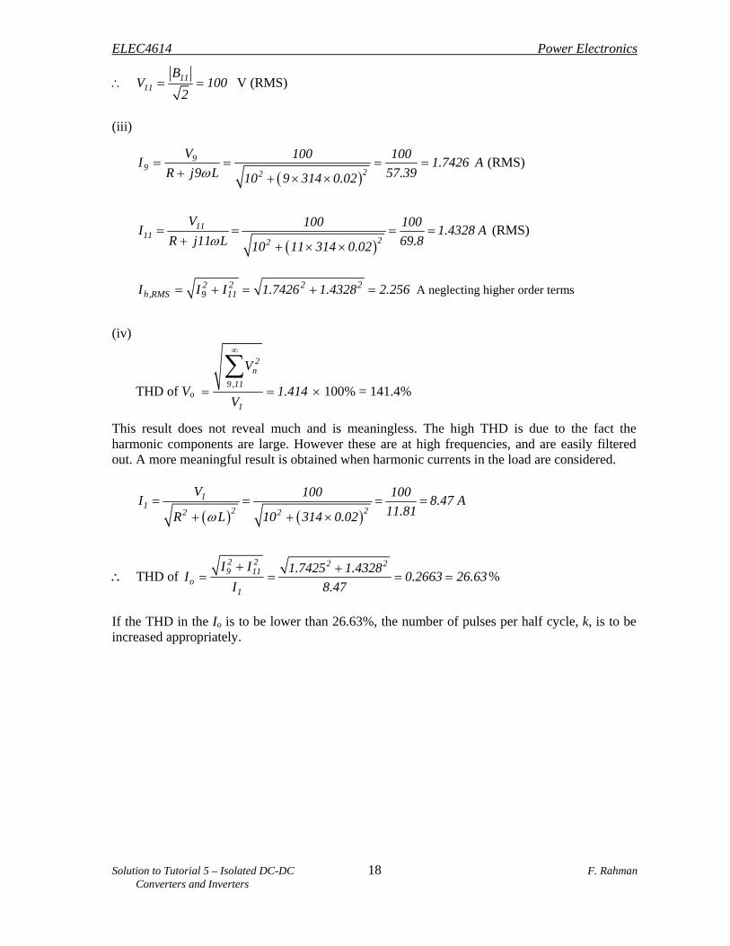
11
11 3 3 11 5 5 11sin sin sin sin sin sin
10 10 10 10 10 10B 0.4 0.5 200
7 7 11 9 9 11sin sin sin sin
10 10 10 10
= 141.4
ELEC4614 Power Electronics
Solution to Tutorial 5 – Isolated DC-DC 18 F. Rahman Converters and Inverters
1111
BV 100
2 V (RMS)
(iii)
99 22
V 100 100I 1.7426 A
R j9 L 57.3910 9 314 0.02
(RMS)
1111
22
V 100 100I 1.4328 A
R j11 L 69.810 11 314 0.02
(RMS)
2 2 2 2h,RMS 9 11I I I 1.7426 1.4328 2.256 A neglecting higher order terms
(iv)
THD of Vo
2n
9 ,11
1
V
1.414V
100% = 141.4%
This result does not reveal much and is meaningless. The high THD is due to the fact the harmonic components are large. However these are at high frequencies, and are easily filtered out. A more meaningful result is obtained when harmonic currents in the load are considered.
1
12 22 2
V 100 100I 8.47 A
11.81R L 10 314 0.02
THD of 2 2 2 29 11
o1
I I 1.7425 1.4328I 0.2663 26.63
I 8.47
%
If the THD in the Io is to be lower than 26.63%, the number of pulses per half cycle, k, is to be increased appropriately.

ELEC4614 Power Electronics
Solution to Tutorial 5 – Isolated DC-DC 19 F. Rahman Converters and Inverters
Vd
20 20
202020
20202020
20202060
60
2 1 2
22 1
t = 0
- Vd
9 (i). The output voltage waveform is
(ii) By taking the t = 0 reference as shown above and using the results of 3,
d 1 2 2n
4V n n nV sin sin cos n j sin n sin cos n j sin n
2 2 2n 2
d 1 2
d
0.9V n nsin 2 sin cos n
n 2 2
0.9Vsin n 30 2 sin n 10 cos n 60
n
d3
0.9VV sin 3 30 2 sin 3 10 cos 3 60
3
10.3 1 2 1 0
2
Hence, the third harmonic in the output is eliminated! For high power inverter circuits, where the switching frequency is quite low, the inverse problem of finding the switching angles so that certain low order output voltage harmonics are eliminated, is often faced. (iii)
d1
d d
0.9VV sin 30 2 sin 10 cos 60
1
0.9V 0.5 0.17 0.606V
The rms value of the output voltage waveform vo is

ELEC4614 Power Electronics
Solution to Tutorial 5 – Isolated DC-DC 20 F. Rahman Converters and Inverters
40 120 160
2 2 2o d d d
20 60 140
d
d
1V V d t V d t V d t
1 100V
180
0.745V
2 2 2 2
o 1
1
V V 0.745 0.606THD 0.715 71.5
V 0.606
%
10.
Note that the line-line voltage waveforms are quasi-square, with amplitude of Vd and = 120. For the Y-connected load, the line-neutral voltage waveforms are stepped square, with amplitude
of d2
V3
. In order to find the line-neutral voltage, the voltage of the neutral point must first be
found by noting the states of the switches and by assuming a purely resistive load. Note that when two of the top switches and one of the bottom switches are ON, the voltage of the neutral
point is d2
V3
. When one of the top switches and two of the bottom switches are ON, the voltage
of the neutral point is d1
V3
. The line- neutral voltage is found by subtracting the voltage of the
D 6 T2 T4
T3T1 D 3
D 4
D 1
V d
D 2
D 5
T6
T5
CA B
R R
R

ELEC4614 Power Electronics
Solution to Tutorial 5 – Isolated DC-DC 21 F. Rahman Converters and Inverters
0 2 3t
vcn
vbn
van
vca
vbc
vab
T1
T3
T5
T2
T4
T6
ON OFF ON
Vd
-Vd
2/3Vd1/3Vd
-1/3Vd-2/3Vd
-1/3Vd-2/3Vd
neutral point from the line voltage. The line-line voltages are found more easily, simply by noting the states of the switches and subtracting the voltage of one line from another.

ELEC4614 Power Electronics
Solution to Tutorial 5 – Isolated DC-DC 22 F. Rahman Converters and Inverters
Vd
b
a
c
T1
2i
i i
n
T2 T6
R R
R
ia
2i
c
b
i
Vd
T1T5
T6
n
During 0<t</3 Top switches T1 & T5 and bottom switch T6 are ON.
dV iR 2iR ; dVi
3R
Potential of the neutral point with respect to the
–ve dc rail is 2iR, i.e., d2V
3.
Since load terminals a and b are at the same potential, vac = 0.
The line-line voltages are:
vab = Vd,; vbc = Vd,; vca = 0 The line-neutral voltages are:
an d n d d d
cn d bn d
2 1v V v V V V ;
3 3
1 2v V ; v V
3 3
During /3<t<2/3 Top switch T1 and bottom switches T2 and T6 are ON.
dV 2i R i R. dVi
3R
n d1
v V3
with respect to the ve dc
rail. The line-line voltages are:
vab = Vd, vbc = 0, vca = Vd The line-neutral voltages are:
an d n d d d1 2
v V v V V V3 3
bn d cn d1 1
v V ; v V3 3

ELEC4614 Power Electronics
Solution to Tutorial 5 – Isolated DC-DC 23 F. Rahman Converters and Inverters
R R
R
ia
2i
b
c
i
Vd
T1T3
T2
n
During 2/3<t< T1, T3 and T2 ON
n d2
v V3
with respect to the –ve dc rail.
The line-line voltages are: vab = 0, vbc = Vd, vca = -Vd. The line – neutral voltages are:
an d bn d cn d1 1 2
v V ; v V ; v V3 3 3
The voltage waveforms in <t<2 are opposite polarity of the voltage in 0<t<.. Furthermore, being a balanced three-phase system, all line voltages are of equal amplitude, as are line-neutral voltages. They also are displaced by 120 between phases. From observation of the waveforms, the rms values are:
dab
n 1,3,5,...
4V n 120v sin cos n t
n 2 3
d1,l l d
4VV sin 60 0.78V
2 = 156 V
5 ,l lV 3 1 .2 1 V ;
7 ,l l 11,l l 13,l l 17 ,l lV 22.29V ; V 14.19V ; V 12V ; V 9.18 V
2 / 3
2o,l l d d
0
1V V d t 0.8165V
V
1,l l
1,l n d
VV 0.45V
3
= 90 V
5,l n 7 ,l n 11,l n 13,l n 17 ,l nV 18.02 V ; V 13.22 V ; V 8.19 V ; V 6.93 V ; V 5.3 V