solutions manual -...
TRANSCRIPT

SOLUTIONS MANUAL
DATA AND COMPUTERCOMMUNICATIONS
EIGHTH EDITIONCHAPTERS 1 - 12
WILLIAM STALLINGS
Copyright 2007: William Stallings

-2-
© 2007 by William Stallings
All rights reserved. No partof this document may bereproduced, in any form orby any means, or posted onthe Internet, withoutpermission in writing fromthe author. Selectedsolutions may be sharedwith students, provided thatthey are not available,unsecured, on the Web.

-3-
NOTICE
This manual contains solutions to all of the review questions andhomework problems in Data and Computer Communications, EighthEdition. If you spot an error in a solution or in the wording of aproblem, I would greatly appreciate it if you would forward theinformation via email to [email protected]. An errata sheet for this manual,if needed, is available at ftp://shell.shore.net/members/w/s/ws/S.
W.S.

-4-
TABLE OF CONTENTS
Chapter 2: Protocol Architecture...................................................................................5Chapter 3: Data Transmission .......................................................................................9Chapter 4: Transmission Media...................................................................................13Chapter 5: Signal Encoding Techniques.....................................................................17Chapter 6: Digital Data Communications Techniques ............................................26Chapter 7: Data Link Control Protocols.....................................................................33Chapter 8: Multiplexing................................................................................................40Chapter 9: Spread Spectrum ........................................................................................45Chapter 10: Circuit Switching and Packet Switching.................................................48Chapter 11: Asynchronous Transfer Mode..................................................................53Chapter 12: Routing in Switched Networks................................................................59

-5-
AA NSWERS TO NSWERS TO QQ U E S T I O N SU E S T I O N S
2.1 The network access layer is concerned with the exchange of data between acomputer and the network to which it is attached.
2.2 The transport layer is concerned with data reliability and correct sequencing.
2.3 A protocol is the set of rules or conventions governing the way in which twoentities cooperate to exchange data.
2.4 A PDU is the combination of data from the next higher communications layer andcontrol information.
2.5 The software structure that implements the communications function. Typically,the protocol architecture consists of a layered set of protocols, with one or moreprotocols at each layer.
2.6 Transmission Control Protocol/Internet Protocol (TCP/IP) are two protocolsoriginally designed to provide low level support for internetworking. The term isalso used generically to refer to a more comprehensive collection of protocolsdeveloped by the U.S. Department of Defense and the Internet community.
2.7 Layering decomposes the overall communications problem into a number of moremanageable subproblems.
2.8 A router is a device that operates at the Network layer of the OSI model to connectdissimilar networks.
2.9 IPv4.
2.10 No, other transport layer protocols, such as UDP, are also used. Some traffic usesno transport protocol, such as ICMP.
2.11 IPv4 - 32 bits; IPv6 - 128 bits
AA NSWERS TO NSWERS TO PP R O B L E M SR O B L E M S
2.1 The guest effectively places the order with the cook. The host communicates thisorder to the clerk, who places the order with the cook. The phone system providesthe physical means for the order to be transported from host to clerk. The cook
CHAPTER 2PROTOCOL ARCHITECTURE, TCP/IP, AND
INTERNET-BASED APPLICATIONS

-6-
gives the pizza to the clerk with the order form (acting as a "header" to the pizza).The clerk boxes the pizza with the delivery address, and the delivery van enclosesall of the orders to be delivered. The road provides the physical path for delivery.
2.2 a.
TelephoneTelephone line
Translator (F → E)French PM
TelephoneTranslator (E → C)
Chinese PM
The PMs speak as if they are speaking directly to each other. For example, when theFrench PM speaks, he addresses his remarks directly to the Chinese PM. However,the message is actually passed through two translators via the phone system. TheFrench PM's translator translates his remarks into English and telephones these tothe Chinese PM's translator, who translates these remarks into Chinese.b.
PhoneTelephone line
Tr (F → G)French PM
Phone PhoneTr (G → J)
PhoneTr (J → C)
Chinese PM
An intermediate node serves to translate the message before passing it on. Notethat the intermediate node handles the message only up to the second level; aminister's level is not needed.
2.3 Perhaps the major disadvantage is the processing and data overhead. There isprocessing overhead because as many as seven modules (OSI model) are invoked tomove data from the application through the communications software. There isdata overhead because of the appending of multiple headers to the data. Anotherpossible disadvantage is that there must be at least one protocol standard per layer.With so many layers, it takes a long time to develop and promulgate the standards.
2.4 No. There is no way to be assured that the last message gets through, except byacknowledging it. Thus, either the acknowledgment process continues forever, orone army has to send the last message and then act with uncertainty.
2.5 A case could be made either way. First, look at the functions performed at thenetwork layer to deal with the communications network (hiding the details fromthe upper layers). The network layer is responsible for routing data through thenetwork, but with a broadcast network, routing is not needed. Other functions,such as sequencing, flow control, error control between end systems, can beaccomplished at layer 2, because the link layer will be a protocol directly betweenthe two end systems, with no intervening switches. So it would seem that anetwork layer is not needed. Second, consider the network layer from the point ofview of the upper layer using it. The upper layer sees itself attached to an accesspoint into a network supporting communication with multiple devices. The layerfor assuring that data sent across a network is delivered to one of a number of otherend systems is the network layer. This argues for inclusion of a network layer.

-7-
In fact, the OSI layer 2 is split into two sublayers. The lower sublayer isconcerned with medium access control (MAC), assuring that only one end systemat a time transmits; the MAC sublayer is also responsible for addressing other endsystems across the LAN. The upper sublayer is called Logical Link Control (LLC).LLC performs traditional link control functions. With the MAC/LLC combination,no network layer is needed (but an internet layer may be needed).
2.6 a. No. This would violate the principle of separation of layers. To layer (N – 1),the N-level PDU is simply data. The (N – 1) entity does not know about theinternal format of the N-level PDU. It breaks that PDU into fragments andreassembles them in the proper order.
b. Each N-level PDU must retain its own header, for the same reason given in (a).
2.7 Data plus transport header plus internet header equals 1820 bits. This data isdelivered in a sequence of packets, each of which contains 24 bits of networkheader and up to 776 bits of higher-layer headers and/or data. Three networkpackets are needed. Total bits delivered = 1820 + 3 × 24 = 1892 bits.
2.8 UDP provides the source and destination port addresses and a checksum thatcovers the data field. These functions would not normally be performed byprotocols above the transport layer. Thus UDP provides a useful, though limited,service.
2.9 In the case of IP and UDP, these are unreliable protocols that do not guaranteedelivery, so they do not notify the source. TCP does guarantee delivery. However,the technique that is used is a timeout. If the source does not receive anacknowledgment to data within a given period of time, the source retransmits.
2.10 UDP has a fixed-sized header. The header in TCP is of variable length.
2.11 Suppose that A sends a data packet k to B and the ACK from B is delayed but notlost. A resends packet k, which B acknowledges. Eventually A receives 2 ACKs topacket k, each of which triggers transmission of packet (k + 1). B will ACK bothcopies of packet (k + 1), causing A to send two copies of packet (k + 2). From nowon, 2 copies of every data packet and ACK will be sent.
2.12 TFTP can transfer a maximum of 512 bytes per round trip (data sent, ACKreceived). The maximum throughput is therefore 512 bytes divided by the round-trip time. Source: [STEV94].
2.13 The "netascii" transfer mode implies the file data are transmitted as lines of ASCIItext terminated by the character sequence {CR, LF}, and that both systems mustconvert between this format and the one they use to store the text files locally.This means that when the "netascii" transfer mode is employed, the file sizes of thelocal and the remote file may differ, without any implication of errors in the datatransfer. For example, UNIX systems terminate lines by means of a single LFcharacter, while other systems, such as Microsoft Windows, terminate lines bymeans of the character sequence {CR, LF}. This means that a given text file willusually occupy more space in a Windows host than in a UNIX system.
2.14 If the same TIDs are used in twice in immediate succession, there's a chance thatpackets of the first instance of the connection that were delayed in the network

-8-
arrive during the life of the second instance of the connection, and, as they wouldhave the correct TIDs, they could be (mistakenly) considered as valid.
2.15 TFTP needs to keep a copy of only the last packet it has sent, since theacknowledgement mechanism it implements guarantees that all the previouspackets have been received, and thus will not need to be retransmitted.
2.16 This could trigger an "error storm". Suppose host A receives an error packet fromhost B, and responds it by sending an error packet back to host B. This packetcould trigger another error packet from host B, which would (again) trigger anerror packet at host A. Thus, error messages would bounce from one host to theother, indefinitely, congesting the network and consuming the resources of theparticipating systems.
2.17 The disadvantage is that using a fixed value for the retransmission timer means thetimer will not reflect the characteristics of the network on which the data transferis taking place. For example, if both hosts are on the same local area network, a 5-second timeout is more than enough. On the other hand, if the transfer is takingplace over a (long delay) satellite link, then a 5-second timeout might be too short,and could trigger unnecessary retransmissions. On the other hand, using a fixedvalue for the retransmission timer keeps the TFTP implementation simple, whichis the objective the designers of TFTP had in mind.
2.18 TFTP does not implement any error detection mechanism for the transmitted data.Thus, reliability depends on the service provided by the underlying transportprotocol (UDP). While the UDP includes a checksum for detecting errors, its use isoptional. Therefore, if UDP checksums are not enabled, data could be corruptedwithout being detected by the destination host.
2.20 a. The internet protocol can be defined as a separate layer. The functionsperformed by IP are clearly distinct from those performed at a network layerand those performed at a transport layer, so this would make good sense.
b. The session and transport layer both are involved in providing an end-to-endservice to the OSI user, and could easily be combined. This has been done inTCP/IP, which provides a direct application interface to TCP.

-9-
AA NSWERS TO NSWERS TO QQ U E S T I O N SU E S T I O N S
3.1 With guided media, the electromagnetic waves are guided along an enclosedphysical path whereas unguided media provide a means for transmittingelectromagnetic waves but do not guide them.
3.2 A continuous or analog signal is one in which the signal intensity varies in asmooth fashion over time while a discrete or digital signal is one in which thesignal intensity maintains one of a finite number of constant levels for some periodof time and then changes to another constant level.
3.3 Amplitude, frequency, and phase are three important characteristics of a periodicsignal.
3.4 2π radians.
3.5 The relationship is λf = v, where λ is the wavelength, f is the frequency, and v is thespeed at which the signal is traveling.
3.6 The fundamental frequency is the lowest frequency component in the Fourierrepresentation of a periodic quantity.
3.7 The spectrum of a signal is the frequencies it contains while the bandwidth of asignal is the width of the spectrum.
3.8 Attenuation is the gradual weakening of a signal over distance.
3.9 The rate at which data can be transmitted over a given communication path, orchannel, under given conditions, is referred to as the channel capacity.
3.10 Bandwidth, noise, and error rate.
AA NSWERS TO NSWERS TO PP R O B L E M SR O B L E M S
3.1 a. If two devices transmit at the same time, their signals will be on the medium atthe same time, interfering with each other; i.e., their signals will overlap andbecome garbled.
b. See discussion in Section 15.3. on medium access control.
3.2 Period = 1/1000 = 0.001 s = 1 ms.
3.3 a. sin (2πft – π) + sin (2πft + π) = 2 sin (2πft + π) or 2 sin (2πft – π) or –2 sin (2πft)b. sin (2πft) + sin (2πft – π) = 0.
CHAPTER 3DATA TRANSMISSION

-10-
3.4N C D E F G A B CF 264 297 330 352 396 440 495 528D 33 33 22 44 44 55 33W 1.25 1.11 1 0.93 0.83 0.75 0.67 0.63
N = note; F = frequency (Hz); D = frequency difference; W = wavelength (m)
3.5 2 sin(4πt + π); A = 2, f = 2, φ = π
3.6 (1 + 0.1 cos 5t) cos 100t = cos 100t + 0.1 cos 5t cos 100t. From the trigonometricidentity cos a cos b = (1/2)(cos(a + b) + cos(a – b)), this equation can be rewritten asthe linear combination of three sinusoids:cos 100t + 0.05 cos 105t + 0.05 cos 95t. Source: [MOSH89]
3.7 We have cos2x = cos x cos x = (1/2)(cos(2x) + cos(0)) = (1/2)(cos(2x) + 1). Then:f(t) = (10 cos t)2 = 100 cos2t = 50 + 50 cos(2t). The period of cos(2t) is π and thereforethe period of f(t) is π.
3.8 If f1(t) is periodic with period X, then f1(t) = f1(t +X) = f1(t +nX) where n is an integerand X is the smallest value such that f1(t) = f1(t +X). Similarly, f2(t) = f2(t +Y) = f2(t +mY). We have f(t) = f1(t) + f2(t). If f(t) is periodic with period Z, then f(t) = f(t + Z).Therefore f1(t) + f2(t) = f1(t + Z) + f2(t + Z). This last equation is satisfied if f1(t) = f1(t+ Z) and f2(t) = f2(t + Z). This leads to the condition Z = nX = mY for some integersn and m. We can rewrite this last as (n/m) = (Y/X). We can therefore conclude thatif the ratio (Y/X) is a rational number, then f(t) is periodic.
3.9 The signal would be a low-amplitude, rapidly changing waveform.
3.10 No transmission medium is capable of transmitting the entire spectrum offrequencies. A real signal therefore is bandlimited, with frequencies above acertain point absent. However, most of the information is in the lower frequencies.This is not a problem if it is remembered that the object of the transmission is tosend signals that represent binary 1s and 0s. Even though there will be somedistortion because of the loss of higher frequencies, the shape of the original pulseis known (by the specifications for the transmission system). Thus, the receiver willusually be able to distinguish a binary 0 from a binary 1.
3.11 A 6-bit code allows only 64 unique characters to be defined. Several shift lock codeswere defined in various versions of TTS (shift, supershift, unshift). These codeschange the meaning of all codes that follow until a new shift lock code appears.Thus, with two shift locks, 3 × (64 - 3) = 183 different codes can be defined. Theactual number is less, since some codes, such as space, are "don't-cares" withrespect to shift locks.
3.12 Refer to the reasoning of Section 3.2. Retaining the vertical resolution of 483 lines,each horizontal line occupies 52.5 µsec. A horizontal resolution of H lines resultsin a maximum of H/2 cycles per line, thus the bandwidth of 5 MHz allows:

-11-
5 MHz = (H/2) / 52.5 µsecH = 525 lines
Now, if we assume the same horizontal resolution of H = 450, then for abandwidth of 5 MHz, the duration of one line is:
5 MHz = (450/2) / TT = 45 µsec
allowing 11 µsec for horizontal retrace, each line occupies 56.2 µsec. The scanningfrequency is:
(1/30 s/scan) /V lines = 56.2 µsec/lineV = 593 lines
3.13 a. (30 pictures/s) (480 × 500 pixels/picture) = 7.2 × 106 pixels/s
Each pixel can take on one of 32 values and can therefore be represented by 5bits:
R = 7.2 × 106 pixels/s × 5 bits/pixel = 36 Mbpsb. We use the formula: C = B log2 (1 + SNR)
B = 4.5 × 10⁶ MHz = bandwidth, andSNRdB = 35 = 10 log10 (SNR), henceSNR = 1035/10 = 103.5, and thereforeC = 4.5 × 10⁶ log2 (1 + 103.5) = 4.5 × 10⁶ × log2 (3163)C = (4.5 × 106 × 11.63) = 52.335 × 10⁶ bps
c. Allow each pixel to have one of ten intensity levels and let each pixel be one ofthree colors (red, blue, green) for a total of 10 × 3 = 30 levels for each pixelelement.
3.14 N = 10 log k + 10 log T + 10 log B= –228.6 dBW + 10 log 104 + 10 log 107
= –228.6 + 40 + 70 = –118.6 dBWSource: [FREE98]
3.15 Using Shannon's equation: C = B log2 (1 + SNR)We have W = 300 Hz (SNR)dB = 3Therefore, SNR = 100.3
C = 300 log2 (1 + 100.3) = 300 log2 (2.995) = 474 bps
3.16 Using Nyquist's equation: C = 2B log2MWe have C = 9600 bpsa. log2M = 4, because a signal element encodes a 4-bit word
Therefore, C = 9600 = 2B × 4, and B = 1200 Hzb. 9600 = 2B × 8, and B = 600 Hz
3.17 N = 1.38 × 10–23 × (50 + 273) × 10,000 = 4.5 × 10⁻¹⁷ watts

-12-
3.18 a. Using Shannon’s formula: C = 3000 log2 (1+400000) = 56 Kbpsb. Due to the fact there is a distortion level (as well as other potentially
detrimental impacts to the rated capacity, the actual maximum will besomewhat degraded from the theoretical maximum. A discussion of theserelevant impacts should be included and a qualitative value discussed.
3.19 Nyquist analyzed the theoretical capacity of a noiseless channel; therefore, in thatcase, the signaling rate is limited solely by channel bandwidth. Shannon addressedthe question of what signaling rate can be achieved over a channel with a givenbandwidth, a given signal power, and in the presence of noise.
3.20 a. Using Shannon's formula C = 106 log2(1 + 63) = 6 MHz.b. Data rate = 4 MHz. Using Nyquist's formula 4 × 106 = 2 × 10⁶ log2 M
M = 22 = 4
3.21 C = B log2 (1 + SNR)20 × 106 = 3 × 10⁶ × log2(1 + SNR)log2(1 + SNR) = 6.671 + SNR = 102SNR = 101
3.22 a. Output waveform:sin (2πf1t) + 1/3 sin (2π(3f1)t) + 1/5 sin (2π(5f1)t) + 1/7 sin (2π (7f1)t)where f1 = 1/T = 1 kHzOutput power = 1/2 (1 + 1/9 + 1/25 + 1/49) = 0.586 watt
b. Output noise power = 8 kHz × 0.1 µWatt/Hz = 0.8 mWattSNR = 0.586/0.0008 = 732.5 (SNR)db = 28.65
3.23 (Eb/N0) = –151 dBW – 10 log 2400 – 10 log 1500 + 228.6 dBW = 12 dBWSource: [FREE98]
3.24Decibels 1 2 3 4 5 6 7 8 9 10Losses 0.8 0.63 0.5 0.4 0.32 0.25 0.2 0.16 0.125 0.1Gains 1.25 1.6 2 2.5 3.2 4.0 5.0 6.3 8.0 10
3.25 For a voltage ratio, we have
NdB = 30 = 20 log(V2/V1)V2/V1 = 1030/20 = 101.5 = 31.6
3.26 Power (dBW) = 10 log (Power/1W) = 10 log20 = 13 dBW

-13-
AA NSWERS TO NSWERS TO QQ U E S T I O N SU E S T I O N S
4.1 The twisting of the individual pairs reduces electromagnetic interference. Forexample, it reduces crosstalk between wire pairs bundled into a cable.
4.2 Twisted pair wire is subject to interference, limited in distance, bandwidth, anddata rate.
4.3 Unshielded twisted pair (UTP) is ordinary telephone wire, with no form ofelectromagnetic shielding around the wire. Shielded twisted pair (STP) surroundsthe wire with a metallic braid or sheathing that reduces interference.
4.4 Optical fiber consists of a column of glass or plastic surrounded by an opaque outerjacket. The glass or plastic itself consists of two concentric columns. The innercolumn called the core has a higher index of refraction than the outer column calledthe cladding.
4.5 Point-to-point microwave transmission has a high data rate and less attenuationthan twisted pair or coaxial cable. It is affected by rainfall, however, especiallyabove 10 GHz. It is also requires line of sight and is subject to interference fromother microwave transmission, which can be intense in some places.
4.6 Direct broadcast transmission is a technique in which satellite video signals aretransmitted directly to the home for continuous operation.
4.7 A satellite must use different uplink and downlink frequencies for continuousoperation in order to avoid interference.
4.8 Broadcast is omnidirectional, does not require dish shaped antennas, and theantennas do not have to be rigidly mounted in precise alignment.
4.9 The two functions of an antenna are: (1) For transmission of a signal, radio-frequency electrical energy from the transmitter is converted into electromagneticenergy by the antenna and radiated into the surrounding environment (atmosphere,space, water); (2) for reception of a signal, electromagnetic energy impinging on theantenna is converted into radio-frequency electrical energy and fed into the receiver.
4.10 An isotropic antenna is a point in space that radiates power in all directionsequally.
4.11 A parabolic antenna creates, in theory, a parallel beam without dispersion. Inpractice, there will be some beam spread. Nevertheless, it produces a highlyfocused, directional beam.
4.12 Effective area and wavelength.
CHAPTER 4TRANSMISSION MEDIA

-14-
4.13 Free space loss.
4.14 Refraction is the bending of a radio beam caused by changes in the speed ofpropagation at a point of change in the medium.
4.15 Diffraction occurs at the edge of an impenetrable body that is large compared tothe wavelength of the radio wave. The edge in effect become a source and wavesradiate in different directions from the edge, allowing a beam to bend around anobstacle. If the size of an obstacle is on the order of the wavelength of the signal orless, scattering occurs. An incoming signal is scattered into several weakeroutgoing signals in unpredictable directions.
AA NSWERS TO NSWERS TO PP R O B L E M SR O B L E M S
4.1 Elapsed time = (5000 km)/(1000 km/hr) = 5 hours = 18,000 seconds
Amount of data per diskette = 1.4 × 10242 × 8 = 11.74 × 106 bits/diskette
Number of diskettes = (107 g)/(30 g/diskette) = 333333 diskettes
Data transfer rate = 11.74 ×106 bits diskette( ) × 333333 diskettes( )
18, 000 seconds= 217 Mbps
4.2 10 log (Po/Pi) = –20dB; Therefore, Po/Pi = 0.01For Pi = 0.5 Watt, Po = 0.005 Watt
SNR = 0.005/(4.5 × 10-6) = 1.11× 10³
SNRdB = 10 log (1.11 × 10³) = 30 dB
4.3 The allowable power loss is 10 × log 100 = 20 dBa. From Figure 4.3, the attenuation is about 13 dB per km.
Length = (20 dB)/(13 dB per km) = 1.5 kmb. Length = (20 dB)/(20 dB per km) = 1 kmc. Length = (20 dB)/(2.5 dB per km) = 8 kmd. Length = (20 dB)/(10 dB per km) = 2 kme. Length = (20 dB)/(0.2 dB per km) = 100 km
4.4 An electromagnetic wave cannot penetrate an enclosing conductor. If the outerconductor of a coaxial cable is everywhere held at ground potential, no externaldisturbance can reach the inner, signal-carrying, conductor.
4.5 From Equation 4,2, the ratio of transmitted power to received power isPt/Pr = (4πd/λ)2
If we double the frequency, we halve λ, or if we double the distance, we double d,so the new ratio for either of these events is:Pt/Pr2 = (8πd/λ)2
Therefore:

-15-
10 log (Pr/Pr2) = 10 log (22) = 6 dB
4.6 We have λf = c; in this case λ × 30 = 3 × 10⁸ m/sec, which yields a wavelength of10,000 km. Half of that is 5,000 km which is comparable to the east-to-westdimension of the continental U.S. While an antenna this size is impractical, the U.S.Defense Department has considered using large parts of Wisconsin and Michiganto make an antenna many kilometers in diameter.
4.7 a. Using λf = c, we have λ = (3 × 10⁸ m/sec)/(300 Hz) = 1,000 km, so thatλ/2 = 500 km.
b. The carrier frequency corresponding to λ/2 = 1 m is given by:f = c/λ = (3 × 10⁸ m/sec)/(2 m) = 150 MHz.
4.8 λ = 2 × 2.5 × 10–3 m = 5 × 10⁻³ mf = c/λ = (3 × 10⁸ m/sec)/( 5 × 10⁻³ m) = 6 × 10¹⁰ Hz = 60 GHz
4.9 The received signal is, essentially, the same. The received power will increase by afactor of 4
4.10 Signal loss is proportional to the square of the frequency. Thus, the higher thefrequency, the higher power is needed to obtain a given SNR. Power is much morereadily available at earth stations than at satellites. Therefore, it makes more senseto put the higher power requirements on the earth stations than on the satellites.
4.11Distance (km) Radio (dB) Wire (dB)
1 –6 –32 –12 –64 –18 –128 –24 –2416 –30 –28
4.12 a. First, take the derivative of both sides of the equation y2 = 2px:
dydxy2 = dy
dx2px( ); 2y dy
dx= 2p; dy
dx=py
Therefore tan β = (p/y1).b. The slope of PF is (y1 – 0)/(x1 – (p/2)). Therefore:
tanα =
y1x1 −
p2
−py1
1+ y1x1 −
p2
py1
=y12 − px1 +
12p2
x1y1 −12py1 + py1
Because y12 = 2px1, this simplifies to tan α = (p/y1).

-16-
4.13 LdB = 20 log(fMHz) + 120 +20 log (dkm) + 60 – 147.56 = 20 log(fMHz) +20 log (dkm) + 32.44
4.14 a. From Appendix 3A, PowerdBW = 10 log (PowerW) = 10 log (50) = 17 dBWPowerdBm = 10 log (PowermW) = 10 log (50,000) = 47 dBm
b. Using Equation (4.3),LdB = 20 log(900 × 106) +20 log (100) – 147.56 = 120 + 59.08 +40 – 147.56 = 71.52Therefore, received power in dBm = 47 – 71.52 = –24.52 dBm
c LdB = 120 + 59.08 +80 – 147.56 =111.52; Pr,dBm = 47 – 111.52 = –64.52 dBmd The antenna gain results in an increase of 3 dB, so that Pr,dBm = –61.52 dBmSource: [RAPP96]
4.15 a. G = 7A/λ2 = 7Af2/c2 = (7 × π × (0.6)2 × (2×109)2]/(3 × 108)2 = 351.85GdB = 25.46 dB
b. 0.1 W x 351.85 = 35.185 Wc. Use LdB = 20 log (4π) + 20 log (d) + 20 log (f) – 20 log (c) – 10 log(Gr) – 10 log (Gt)
LdB = 21.98 + 87.6 + 186.02 – 169.54 – 25.46 – 25.46 = 75.14 dBThe transmitter power, in dBm is 10 log (100) = 20.The available received signal power is 20 – 75.14 = –55.14 dBm
4.16
By the Pythagorean theorem: d2 + r2 = (r + h)2
Or, d2 = 2rh + h2. The h2 term is negligible with respect to 2rh, so we use d2 = 2rh.
Then, dkm = 2rkm hkm = 2rkmhm /1000 = 2 × 6.37 × hm = 3.57 hm
4.17 For radio line of sight, we use d = 3.57 Kh , with K = 4/3, we have802 = (3.57)2 × 1.33 × h. Solving for h, we get h = 378 m.
4.18 Let RI = refractive index, α = angle of incidence, β = angle of refraction
(sin α)/sin β) = RIair/RIwater = 1.0003/(4/3) = 0.75sin β = 0.5/0.75 = 0.66; β = 41.8°

-17-
AA NSWERS TO NSWERS TO QQ U E S T I O N SU E S T I O N S
5.1 Signal spectrum: A lack of high-frequency components means that less bandwidthis required for transmission. In addition, lack of a direct-current (dc) componentmeans that ac coupling via transformer is possible. The magnitude of the effects ofsignal distortion and interference depend on the spectral properties of thetransmitted signal. Clocking: Encoding can be used to synchronize the transmitterand receiver. Error detection: It is useful to have some error detection capabilitybuilt into the physical signaling encoding scheme. Signal interference and noiseimmunity: Certain codes exhibit superior performance in the presence of noise.Cost and complexity: The higher the signaling rate to achieve a given data rate, thegreater the cost. Some codes require a signaling rate that is in fact greater than theactual data rate.
5.2 In differential encoding, the signal is decoded by comparing the polarity of adjacentsignal elements rather than determining the absolute value of a signal element.
5.3 Non return-to-zero-level (NRZ-L) is a data encoding scheme in which a negativevoltage is used to represent binary one and a positive voltage is used to representbinary zero. As with NRZ-L, NRZI maintains a constant voltage pulse for theduration of a bit time. The data themselves are encoded as the presence or absenceof a signal transition at the beginning of the bit time. A transition (low to high orhigh to low) at the beginning of a bit time denotes a binary 1 for that bit time; notransition indicates a binary 0.
5.4 For bipolar-AMI scheme, a binary 0 is represented by no line signal, and a binary 1is represented by a positive or negative pulse. The binary 1 pulses must alternate inpolarity. For pseudoternary, a binary 1 a is represented by the absence of a linesignal, and a binary 0 by alternating positive and negative pulses.
5.5 A biphase scheme requires at least one transition per bit time and may have asmany as two transitions. In the Manchester code, there is a transition at the middleof each bit period; a low-to-high transition represents a 1, and a high-to-lowtransition represents a 0. In differential Manchester, the midbit transition is usedonly to provide clocking. The encoding of a 0 is represented by the presence of atransition at the beginning of a bit period, and a 1 is represented by the absence of atransition at the beginning of a bit period.
5.6 In a scrambling technique, sequences that would result in a constant voltage levelon the line are replaced by filling sequences that will provide sufficient transitionsfor the receiver's clock to maintain synchronization. The filling sequence must berecognized by the receiver and replaced with the original data sequence. The fillingsequence is the same length as the original sequence, so there is no data ratepenalty.
CHAPTER 5SIGNAL ENCODING TECHNIQUES

-18-
5.7 A modem converts digital information into an analog signal, and conversely.
5.8 With amplitude-shift keying, binary values are represented by two differentamplitudes of carrier frequencies. This approach is susceptible to sudden gainchanges and is rather inefficient.
5.9 The difference is that offset QPSK introduces a delay of one bit time in the Q stream
5.10 QAM takes advantage of the fact that it is possible to send two different signalssimultaneously on the same carrier frequency, by using two copies of the carrierfrequency, one shifted by 90˚ with respect to the other. For QAM, each carrier isASK modulated.
5.11 The sampling rate must be higher than twice the highest signal frequency.
5.12 Frequency modulation (FM) and phase modulation (PM) are special cases of anglemodulation. For PM, the phase is proportional to the modulating signal. For FM,the derivative of the phase is proportional to the modulating signal.
AA NSWERS TO NSWERS TO PP R O B L E M SR O B L E M S
5.1 NRZI, Differential Manchester
5.2 NRZ-L produces a high level for binary 0 and a low level for binary 1. Map thislevel as indicated by the definition for 1 and 0 for each of the other codes.
5.3 First, E-NRZ provides a minimum transition rate that reduces the dc component.Second, under worst case, E-NRZ provides a minimum of one transition for every14 bits, reducing the synchronization problem. Third, the parity bit provides anerror check. The disadvantages of E-NRZ are added complexity and the overheadof the extra parity bit.
5.4
-19-
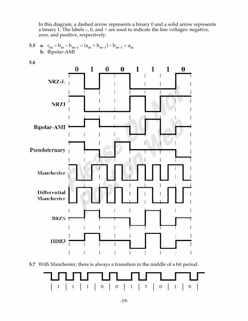
In this diagram, a dashed arrow represents a binary 0 and a solid arrow representsa binary 1. The labels –, 0, and + are used to indicate the line voltages: negative,zero, and positive, respectively.
5.5 a. cm = bm – bm–1 = (am + bm–1) – bm–1 = amb. Bipolar-AMI
5.6
5.7 With Manchester, there is always a transition in the middle of a bit period.
1 1 1 0 0 1 1 0 1 0

-20-
5.8
5.9 The error is at bit position 7, where there is a negative pulse. For AMI, positive andnegative pulses are used alternately for binary 1. The pulse in position 1 representsthe third binary 1 in the data stream and should have a positive value.
5.10
+ – 0 + – 0 – +
could have been produced by either
+ – 0 + – + – +
+ – 0 + – 0 – +
or
+ – 0 + 0 0 – +
+ – 0 + – 0 – +
BPV
error: converted to 0
error: converted to –

-21-
5.11
ASK
BFSK
BPSK
0 1 1 0 0
5.12 Ts = signal element period; Tb = bit period; A = amplitude = 0.005a. Ts = Tb = 10-5 sec
P =1Ts
s2 t( )0
Ts
∫ =A2
2
Eb = P × Tb = P × Ts =A2
2×Ts ; N0 = 2.5 ×10⁻⁸ ×Ts
EbN0
=A2 2( ) ×Ts
2.5 ×10⁻⁸ × Ts= 500 ; Eb N0( )dB =10 log500 = 27 dB
b.
Tb =Ts2
; Eb = P ×Ts2
; N0 = 2.5 ×10⁻⁸ ×Ts
Eb N0( ) = 250; Eb N0( )dB = 10log 250 =24dB
5.13 Each signal element conveys two bits. First consider NRZ-L. It should be clearthat in this case, D = R/2. For the remaining codes, one must first determine theaverage number of pulses per bit. For example, for Biphase-M, there is an averageof 1.5 pulses per bit. We have a pulse rate of P, which yields a data rate of
R = P/1.5D = P/2 = (1.5 x R)/2 = 0.75 × R
5.14 Eb/N0 = (S/N) (B/R)

-22-
S/N = (R/B) (Eb/N0) = 1 × (Eb/N0)(S/N)dB = (Eb/N0)dB
For FSK and ASK, from Figure 5.4, (Eb/N0)dB = 13.5 dB(S/N)dB = 13.5 dB
For PSK, from Figure 5.4, (Eb/N0)dB = 10.5(S/N)dB = 10.5 dB
For QPSK, the effective bandwidth is halved, so that(R/B) = 2(R/B)dB = 3(S/N)dB = 3 + 10.5 = 13.5 dB
5.15 For ASK, BT = (1 + r)R = (1.5)2400 = 3600 HzFor FSK, BT = 2 Δ F + (1 + r)R = 2(2.5 x 10³) + (1.5)2400 = 8600 Hz
5.16 For multilevel signaling BT = [(1 + r)/log2L]RFor 2400 bps QPSK, log2L = log24 = 2
BT = (2/2)2400 = 2400 Hz, which just fits the available bandwidth
For 8-level 4800 bps signaling, log2L = log28 = 3
BT = (2/3)(4800) = 3200 Hz, which exceeds the available bandwidth
5.17 s(t) = d1(t)cos wct + d2(t)sin wct
Use the following identities: cos2α = 2cos2α – 1; sin2α = 2sinα cosα
s(t) coswct = d1(t)cos2wct + d2(t)sinwct coswct= (1/2)d1(t) + (1/2)d1(t) cos2wct + (1/2)d2(t) sin2wct
Use the following identities: cos2α = 1 – 2 sin2α; sin2α = 2sinα cosα
s(t) sinwct = d1(t) coswct sinwct + d2(t)sin2wct= (1/2)d1(t) sin2wct + (1/2)d2(t) - (1/2)d2(t) cos2wct
All terms at 2wc are filtered out by the low-pass filter, yielding:
y1(t) = (1/2)d1(t); y2(t) = (1/2)d2(t)
5.18 As was mentioned in the text, analog signals in the voice band that representdigital data have more high frequency components than analog voice signals.These higher components cause the signal to change more rapidly over time.Hence, DM will suffer from a high level of slope overload noise. PCM, on the

-23-
other hand, does not estimate changes in signals, but rather the absolute value ofthe signal, and is less affected than DM.
5.19 No. The demodulator portion of a modem expects to receive a very specific type ofwaveform (e.g., ASK) and would not produce meaningful output with voice input.Thus, it would not function as the coder portion of a codec. The case against usinga codec in place of a modem is less easily explained, but the following intuitiveargument is offered. If the decoder portion of a codec is used in place of themodulator portion of a modem, it must accept an arbitrary bit pattern, interpretgroups of bits as a sample, and produce an analog output. Some very wide valueswings are to be expected, resulting in a strange-looking waveform. Given theeffects of noise and attenuation, the digital output produced at the receiving endby the coder portion of the codec will probably contain many errors.
5.20 From the text, (SNR)db = 6.02 n + 1.76, where n is the number of bits used forquantization. In this case, (SNR)db = 60.2 + 1.76 = 61.96 dB.
5.21 a. (SNR)db = 6.02 n + 1.76 = 30 dBn = (30 – 1.76)/6.02 = 4.69Rounded off, n = 5 bitsThis yields 25 = 32 quantization levels
b. R = 7000 samples/s × 5 bits/sample = 35 Kbps
5.22 The maximum slope that can be generated by a DM system is δ/Ts = δ fswhere Ts = period of sampling; fs = frequency of samplingConsider that the maximum frequency component of the signal is
w(t) = A sin2πfat
The slope of this component is dw(t)/dt = A2 π fa cos2 π fa t
and the maximum slope is A2 π fa. To avoid slope overload, we require that
δ fs > A2 π fa or δ >
2πf aAf s
5.23 a. A total of 28 quantization levels are possible, so the normalized step size is 2–8
= 0.003906.b. The actual step size, in volts, is: 0.003906 × 10V = 0.03906V
c. The maximum normalized quantized voltage is 1 – 2–8 = 0.9961. Thus theactual maximum quantized voltage is:
0.9961 × 10V = 9.961V
d. The normalized step size is 2–8. The maximum error that can occur is one-halfthe step size. Therefore, the normalized resolution is:
+ 1/2 × 2–8 = 0.001953

-24-
e. The actual resolution is + 0.001953 × 10V = + 0.01953Vf. The percentage resolution is + 0.001953 × 100% = + 0.1953 %
5.24
DM output
0
1
slope overload distortions
5.25 s(t) = Ac cos[2πfct + φ(t)] = 10 cos [(108)πt + 5 sin 2π(103)t]Therefore, φ(t) = 5 sin 2π(103)t, and the maximum phase deviation is 5 radians. Forfrequency deviation, recognize that the change in frequency is determined by thederivative of the phase:φ'(t) = 5 (2π) (103) cos 2π(103)twhich yields a frequency deviation of Δf = (1/2π)[ 5 (2π) (103)] = 5 kHz
5.26 a. s(t) = Ac cos[2πfct + npm(t)] = 10 cos [2π(106)t + 0.1 sin (103)πt]Ac = 10; fc = 106
10 m(t) = 0.1 sin (103)πt, so m(t) = 0.01 sin (103)πtb. s(t) = Ac cos[2πfct + φ(t)] = 10 cos [2π(106)t + 0.1 sin (103)πt]
Ac = 10; fc = 106
φ(t) = 0.1 sin (103)πt, so φ'(t) = 100π cos (103)πt = nfm(t) = 10 m(t)Therefore m(t) = 10π cos (103)πt
5.27 a. For AM, s(t) = [1 + m(t)] cos(2πfct)s1(t) = [1 + m1(t)] cos(2πfct); s2(t) = [1 + m2(t)] cos(2πfct)For the combined signal mc(t) = m1(t) + m2(t),

-25-
sc(t) = [1 + m1(t) + m2(t)] cos(2πfct) = s1(t) + s2(t) – 1, which is a linearcombination of s1(t) and s2(t).
b. For PM, s(t) = A cos(2πfct + npm(t))s1(t) = A cos(2πfct + npm1(t)); s2(t) = A cos(2πfct + npm2(t))For the combined signal mc(t) = m1(t) + m2(t),sc(t) = A cos(2πfct + np[m1(t) + m2(t)]), which is not a linear combination of s1(t)and s2(t).

-26-
AA NSWERS TO NSWERS TO QQ U E S T I O N SU E S T I O N S
6.1 The beginning of a character is signaled by a start bit but with a value of binaryzero. A stop (binary one) follows the character.
6.2 Asynchronous transmission requires an overhead of two or three bits per character,and is, therefore, significantly less efficient than synchronous transmission.
6.3 One possibility is to provide a separate clock line between transmitter and receiver.One side (transmitter or receiver) pulses the line regularly with one short pulse perbit time. The other side uses these regular pulses as a clock. Another alternative isto embed the clocking information in the data signal. For digital signals, this can beaccomplished with Manchester or differential Manchester encoding. For analogsignals, a number of techniques can be used; for example, the carrier frequencyitself can be used to synchronize the receiver based on the phase of the carrier.
6.4 A check bit appended to an array of binary digits to make the sum of all the binarydigits, including the check bit, always odd (odd parity) or always even (evenparity).
6.5 An error detecting code in which the code is the remainder resulting from dividingthe bits to be checked by a predetermined binary number.
6.6 The CRC has more bits and therefore provides more redundancy. That is, itprovides more information that can be used to detect errors.
6.7 Modulo 2 arithmetic, polynomials, and digital logic.
6.8 It is possible. You could design a code in which all codewords are at least a distanceof 3 from all other codewords, allowing all single-bit errors to be corrected. Supposethat some but not all codewords in this code are at least a distance of 5 from allother codewords. Then for those particular codewords, but not the others, a double-bit error could be corrected.
6.9 An (n, k) block code encodes k data bits into n-bit codewords.
AA NSWERS TO NSWERS TO PP R O B L E M SR O B L E M S
6.1 a. Each character has 25% overhead. For 10,000 characters, there are 20,000 extrabits. This would take an extra 20,000/2400 = 8.33 seconds.
b. The file takes 10 frames or 480 additional bits. The transmission time for theadditional bits is 480/2400 = 0.2 seconds.
c. Ten times as many extra bits and ten times as long for both.
CHAPTER 6DIGITAL DATA COMMUNICATION TECHNIQUES

-27-
d. The number of overhead bits would be the same, and the time would bedecreased by a factor of 4 = 9600/2400.
6.2 For each case, compute the fraction g of transmitted bits that are data bits. Then themaximum effective data rate R is: R = gx, where x is the data rate on the line.a. There are 7 data bits, 1 start bit, 1.5 stop bits, and 1 parity bit
g = 7/(1 + 7 + 1 + 1.5) = 7/10.5 = 0.67R = 0.67 x
b. Each frame contains 48 control bits + 128 information bits = 176 bits. Thenumber of characters is 128/8 = 16, and the number of data bits is 16 × 7 = 112.
R = (112/176)B = 0.64xc. Each frame contains 48 + 1024 = 1072 bits. The number of characters is 1024/8
= 128, and the number of data bits is 128 × 7 = 896.R = (896/1072)B = 0.84x
6.3 Use 1-bit START and STOP bits. Write down a few dozen characters. Choose azero in the first characters as a START bit, count out eight bits, call the next bitSTOP (even if it is a zero), look for the next zero, and call that the START bit of thenext character. Since some 1's will intervene before you find that zero, you willhave moved the starting point of the framing process. Eventually, you will achieveproper framing.
6.4 Not for asynchronous transmission. The stop bit is needed so that the start bit canbe recognized as such. The start bit is the synchronization event, but it must berecognizable. The start bit is always a 0, and the stop bit is always a 1, which is alsothe idle state of the line. When a start bit occurs, it is guaranteed to be differentfrom the current state of the line.
6.5 Let the bit duration be T. Then a frame is 12T long. Let a clock period be T'. The lastbit (bit 12) is sampled at 11.5T'. For a fast running clock, the condition to satisfy is
11.5 ′ T > 11T ⇒
T′ T
<11.511
= 1.045 ⇒ f clock < 1.045 fbit
For a slow running clock, the condition to satisfy is
11.5 ′ T < 12T ⇒
T′ T
>11.512
= 0.958 ⇒ fclock > 0.958f bit
Therefore, the overall condition: 0.958 fbit < fclock <1.045 fbit
6.6 In worst-case conditions, the two clocks will drift in opposite directions. Theresultant accuracy is 2 minutes in 1 year or:2/(60 × 24 × 365) = 0.0000038The allowable error is 0.4Therefore, number of bits is 0.4/0.0000038 = 105,000 bits
6.7 The inclusion of a parity bit extends the message length. There are more bits thatcan be in error since the parity bit is now included. The parity bit may be in errorwhen there are no errors in the corresponding data bits. Therefore, the inclusion ofa parity bit with each character would change the probability of receiving a correctmessage.

-28-
6.8 The receiver won't detect the error, as a parity check bit only detects inversion ofan odd number of bits.
6.9 Any arithmetic scheme will work if applied in exactly the same way to the forwardand reverse process. The modulo 2 scheme is easy to implement in circuitry. It alsoyields a remainder one bit smaller than binary arithmetic.
6.10 a. We have:Pr [single bit in error] = 10–3
Pr [single bit not in error] = 1 – 10–3 = 0.999Pr [8 bits not in error] = (1 – 10–3)8 = (0.999)8 = 0.992Pr [at least one error in frame] = 1 – (1 – 10–3)8 = 0.008
b. Pr [at least one error in frame] = 1 – (1 – 10–3)10 = 1 – (0.999)10 = 0.01

-29-
6.11 a.
b.
Shift Shift Register Input0 0 0 0 0 0 0 0 0 0 0 0 0 0 0 0
1 0 0 0 1 0 0 0 0 0 0 1 0 0 0 0 1 12 0 0 1 0 0 0 0 0 0 1 0 0 0 0 1 0 03 0 1 0 0 0 0 0 0 1 0 0 0 0 1 0 0 04 1 0 0 0 0 0 0 1 0 0 0 0 1 0 0 0 05 0 0 0 1 0 0 1 0 0 0 1 1 0 0 0 1 06 0 0 1 0 0 1 0 0 0 1 1 0 0 0 1 0 07 0 1 0 0 1 0 0 0 1 1 0 0 0 1 0 0 08 1 0 0 1 0 0 0 1 1 0 0 0 1 0 0 0 09 0 0 1 1 0 0 1 1 0 0 1 1 0 0 0 1 010 0 1 1 0 0 1 1 0 0 1 1 0 0 0 1 0 011 1 1 0 0 1 1 0 0 1 1 0 0 0 1 0 0 012 1 0 0 0 1 0 0 1 1 0 1 0 1 0 0 1 013 0 0 0 0 0 0 1 1 0 1 1 1 0 0 1 1 014 0 0 0 0 0 1 1 0 1 1 1 0 0 1 1 0 015 0 0 0 0 1 1 0 1 1 1 0 0 1 1 0 0 016 0 0 0 1 1 0 1 1 1 0 0 1 1 0 0 0 0
CRC
6.12 At the conclusion of the data transfer, just before the CRC pattern arrives, the shiftregister should contain the identical CRC result. Now, the bits of the incoming

-30-
CRC are applied at point C4 (Figure 6.5). Each 1 bit will merge with a 1 bit(exclusive-or) to produce a 0; each 0 bit will merge with a 0 bit to produce a zero.
6.13
6.14 a.
C2C3
⊕
⊕ C1 C0
Input
b. Data = 1 0 0 1 1 0 1 1 1 0 0M(X) = 1 + X3 + X4 + X6 + X7 + X8
X4M(X) = X12 + X11 + X10 + X8 + X7 + X4
X4M X( )
P X( )= X12 +X11 +X10 +X8 +X7 +
X2
P X( )
R(X) = X2
T(X) = X4M(X) + R(X) = X12 + X11 + X10 + X8 + X7 + X4 + X2
Code = 0 0 1 0 1 0 0 1 1 0 1 1 1 0 0
c. Code = 0 0 1 0 1 0 0 0 1 0 1 1 1 0 0
T X( )P X( )
yields a nonzero remainder
6.15 a. Divide X10 + X7 + X4 + X3 + X + 1 by X4 + X + 1. The remainder is X3 + X2. TheCRC bits are 1100. The string 100100110111100 is sent.
b. The string 000110110111100 is received, corresponding to X11 + X10 + X8 + X7 +
-31-
X5 + X4 + X3 + X2. The remainder after division by X4 + X + 1 is X3 + X2 + X ,which is nonzero. The errors are detected.
c. The string 000010110111100 is received, corresponding to X10 + X8 + X7 + X5 +X4 + X3 + X2. The remainder after division by X4 + X + 1 is zero. The errors arenot detected.
6.16 a. The multiplication of D(X) by X16 corresponds to shifting D(X) 16 places andthus providing the space for a 16-bit FCS. The addition of XkL(X) to X16D(X)inverts the first 16 bits of D(X) (ones complement). The addition of L(X) to R(X)inverts all of the bits of R(X).
b. The HDLC standard provides the following explanation. The addition ofXKL(X) corresponds to a value of all ones. This addition protects against theobliteration of leading flags, which may be non-detectable if the initialremainder is zero. The addition of L(X) to R(X) ensures that the received, error-free message will result in a unique, non-zero remainder at the receiver. Thenon-zero remainder protects against the potential non-detectability of theobliteration of trailing flags.
c. The implementation is the same as that shown in Solution 6.11b, with thefollowing strategy. At both transmitter and receiver, the initial content of theregister is preset to all ones. The final remainder, if there are no errors, will be0001 1101 0000 1111.
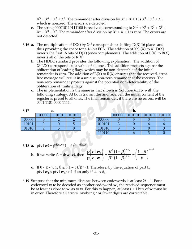
6.17 a. b.00000 10101 01010 000000 010101 101010 110110
00000 0 2 2 000000 0 3 3 410101 3 0 5 010101 3 0 6 601010 2 5 0 101010 3 6 0 3
110110 4 6 3 0
6.18 a. p(v|w) = βd(w,v)(1 – β)(n – d(w,v)
b. If we write di = d(wi,v), then
p v|w1( )p v|w2( )
=β d1 1− β( )n−d1
β d2 1− β( )n−d2=1− ββ
d2 −d1
c. If 0 < β < 0.5, then (1 – β)/β > 1. Therefore, by the equation of part b,p(v|w1)/p(v|w2) > 1 if an only if d1 < d2.
6.19 Suppose that the minimum distance between codewords is at least 2t + 1. For acodeword w to be decoded as another codeword w', the received sequence mustbe at least as close to w' as to w. For this to happen, at least t + 1 bits of w must bein error. Therefore all errors involving t or fewer digits are correctable.

-32-
6.20.
CallingDTE
DCE(modem)
DCE(modem)
CalledDTE
EIA-232 EIA-232Network
CD onCC on
Number ofcalled modemsent to calling
modem
CF on
BBCF offCA on
CB onBA
CA offCB offCF offCD offCC off
Connection setup
Carrier on
Data tones
Carrier off
Carrier on
Data tones
Carrier offCarrier off
Time
CD onCC on
CE onCA on
BACB on
CA offCB off
CF on
BB
CA offCB offCF offCD offCC off
6.21 If a device asserts Request to Send, it will get back a Clear to Send and the otherdevice will get a Carrier Detect. If a device asserts Data Terminal Ready, the otherdevice is alerted with a Data Set Ready and a Ring Indicator. Data transmitted byone side are received by the other. In order to operate a synchronous data linkwithout a modem, clock signals need to be supplied. The Transmitter and ReceiveTiming leads are cross-connected for this purpose.
6.22 Circuit SD (Send Data) and Circuit RD (Receive Data) are disconnected or isolatedfrom the remote DTE at the interface and connected to each other in the remoteDCE.

-33-
AA NSWERS TO NSWERS TO QQ U E S T I O N SU E S T I O N S
7.1 Frame synchronization: The beginning and end of each frame must berecognizable. Flow control: The sending station must not send frames at a ratefaster than the receiving station can absorb them. Error control: Bit errorsintroduced by the transmission system should be corrected. Addressing: On amultipoint line, such as a local area network (LAN), the identity of the two stationsinvolved in a transmission must be specified. Control and data on same link: Thereceiver must be able to distinguish control information from the data beingtransmitted. Link management: The initiation, maintenance, and termination of asustained data exchange require a fair amount of coordination and cooperationamong stations. Procedures for the management of this exchange are required.
7.2 The function performed by a receiving entity to limit the amount or rate of data thatis sent by a transmitting entity.
7.3 A flow control protocol in which the sender transmits a block of data and thenawaits an acknowledgment before transmitting the next block.
7.4 (1) The buffer size of the receiver may be limited. (2) The longer the transmission,the more likely that there will be an error, necessitating retransmission of the entireframe. With smaller frames, errors are detected sooner, and a smaller amount ofdata needs to be retransmitted. (3) On a shared medium, such as a LAN, it isusually desirable not to permit one station to occupy the medium for an extendedperiod, thus causing long delays at the other sending stations.
7.5 A method of flow control in which a transmitting station may send numberedpackets within a window of numbers. The window changes dynamically to allowadditional packets to be sent.
7.6 The stop-and-wait approach requires acknowledgments after each frame. Thesliding window flow control technique can send multiple frames before waiting foran acknowledgment. Efficiency can be greatly improved by allowing multipleframes to be in transit at the same time.
7.7 The inclusion of an acknowledgment to a previously received packet in an outgoingdata packet.
7.8 Error control refers to mechanisms to detect and correct errors that occur in thetransmission of frames.
7.9 Error detection; positive acknowledgment; retransmission after timeout; negativeacknowledgment.
CHAPTER 7DATA LINK CONTROL PROTOCOLS

-34-
7.10 A feature that automatically initiates a request for retransmission when an error intransmission is detected.
7.11 Stop-and-wait ARQ: Based on stop-and-wait flow control. A station retransmitson receipt of a duplicate acknowledgment or as a result of a timeout. Go-back-NARQ: Based on sliding-window flow control. When an error is detected, the framein question is retransmitted, as well as all subsequent frames that have beenpreviously transmitted. Selective-reject ARQ. Based on sliding-window flowcontrol. When an error is detected, only the frame in question is retransmitted.
7.12 Primary station: Responsible for controlling the operation of the link. Framesissued by the primary are called commands. Secondary station: Operates underthe control of the primary station. Frames issued by a secondary are calledresponses. The primary maintains a separate logical link with each secondarystation on the line. Combined station: Combines the features of primary andsecondary. A combined station may issue both commands and responses.
7.13 Normal response mode (NRM): Used with an unbalanced configuration. Theprimary may initiate data transfer to a secondary, but a secondary may onlytransmit data in response to a command from the primary. Asynchronousbalanced mode (ABM): Used with a balanced configuration. Either combinedstation may initiate transmission without receiving permission from the othercombined station. Asynchronous response mode (ARM): Used with anunbalanced configuration. The secondary may initiate transmission withoutexplicit permission of the primary. The primary still retains responsibility for theline, including initialization, error recovery, and logical disconnection.
7.14 The flag field delimits the beginning and end of a frame.
7.15 Data transparency refers to the ability to include arbitrary bit patterns in the datafield of a frame without any pattern being confused with part of the controlinformation in the frame. This is achieved by bit stuffing.
7.16 Information frames (I-frames) carry the data to be transmitted for the user (thelogic above HDLC that is using HDLC). Additionally, flow and error control data,using the ARQ mechanism, are piggybacked on an information frame.Supervisory frames (S-frames) provide the ARQ mechanism when piggybackingis not used. Unnumbered frames (U-frames) provide supplemental link controlfunctions.
AA NSWERS TO NSWERS TO PP R O B L E M SR O B L E M S
7.1 a. Because only one frame can be sent at a time, and transmission must stop untilan acknowledgment is received, there is little effect in increasing the size of themessage if the frame size remains the same. All that this would affect is connectand disconnect time.
b. Increasing the number of frames would decrease frame size (number ofbits/frame). This would lower line efficiency, because the propagation time isunchanged but more acknowledgments would be needed.
c. For a given message size, increasing the frame size decreases the number offrames. This is the reverse of (b).

-35-
7.2
105103
104
105
106
106
Data rate R (bps) (log scale)107 108
7.3 Let L be the number of bits in a frame. Then, using Equation 7.5 of Appendix 7A:
a = Propagation Delay
Transmission Time=20 ×10−3
L 4 × 10³( )=80L
Using Equation 7.4 of Appendix 7A:
U =1
1 + 2a=
11 + 160 L( )
≥ 0.5
L ≥160
Therefore, an efficiency of at least 50% requires a frame size of at least 160 bits.
7.4 a = Propagation Delay
L R=
270 ×10−3
103 106 = 270
a. U = 1/(1 + 2a) = 1/541 = 0.002b. Using Equation 7.6: U = W/(1 + 2a) = 7/541 = 0.013c. U = 127/541 = 0.23d. U = 255/541 = 0.47

-36-
7.5 A → B: Propagation time = 4000 × 5 µsec = 20 msecTransmission time per frame =
1000
100 × 103 = 10 msec
B → C: Propagation time = 1000 × 5 µsec = 5 msecTransmission time per frame = x = 1000/RR = data rate between B and C (unknown)
A can transmit three frames to B and then must wait for the acknowledgmentof the first frame before transmitting additional frames. The first frame takes 10msec to transmit; the last bit of the first frame arrives at B 20 msec after it wastransmitted, and therefore 30 msec after the frame transmission began. It will takean additional 20 msec for B's acknowledgment to return to A. Thus, A can transmit3 frames in 50 msec.
B can transmit one frame to C at a time. It takes 5 + x msec for the frame to bereceived at C and an additional 5 msec for C's acknowledgment to return to A.Thus, B can transmit one frame every 10 + x msec, or 3 frames every 30 + 3x msec.Thus:
30 + 3x = 50x = 6.66 msecR = 1000/x = 150 kbps
7.6 Round trip propagation delay of the link = 2 × L × t
Time to transmit a frame = B/R
To reach 100% utilization, the transmitter should be able to transmit framescontinuously during a round trip propagation time. Thus, the total number offrames transmitted without an ACK is:
N =
2 × L × tB R
+1
, where X is the smallest integer greater than or equal to X
This number can be accommodated by an M-bit sequence number with:
M = log2 N( )
7.7 In fact, a REJ is not needed at all, since the sender will time out if it fails to receivean ACK. The REJ improves efficiency by informing the sender of a bad frame asearly as possible.
7.8 Assume a 2-bit sequence number:1. Station A sends frames 0, 1, 2 to station B.2. Station B receives all three frames and cumulatively acknowledges with RR 3.3. Because of a noise burst, the RR 3 is lost.4. A times out and retransmits frame 0.

-37-
5. B has already advanced its receive window to accept frames 3, 0, 1, 2. Thus itassumes that frame 3 has been lost and that this is a new frame 0, which itaccepts.
7.9 Use the following formulas:
a 0.1 1. 10 100S&W (1 – P)/1.2 (1 – P)/3 (1 – P)/21 (1 – P)/201
GBN (7) (1–P)/(1+0.2P) (1–P)/(1+2P) 7(1–P)/21(1+6P)
7(1 – P)/201(1+6P)
GBN (127) (1–P)/(1+0.2P) (1–P)/(1+2P) (1 – P)/(1+20P) 127(1–P)/201(1+126P)
SREJ (7) 1 – P 1 – P 7(1 – P)/21 7(1 – P)/201SREJ (127) 1 – P 1 – P 1 – P 127(1 – P)/201
For a given value of a, the utilization values change very little as a function of Pover a reasonable range (say 10–3 to 10–12). We have the following approximatevalues for P = 10–6:
a 0.1 1.0 10 100Stop-and-wait 0.83 0.33 0.05 0.005
GBN (7) 1.0 1.0 0.33 0.035GBN (127) 1.0 1.0 1.0 0.63SREJ (7) 1.0 1.0 0.33 0.035
SREJ (127) 1.0 1.0 1.0 0.63
7.10 a.
0 1 2 3 4 5 6 7 0• • • • • •
b.
0 1 2 3 4 5 6 7 0• • • • • •
c.
0 1 2 3 4 5 6 7 0• • • • • •
7.11 A lost SREJ frame can cause problems. The sender never knows that the frame was
not received, unless the receiver times out and retransmits the SREJ.

-38-
7.12 From the standard: "A SREJ frame shall not be transmitted if an earlier REJexception condition has not been cleared (To do so would request retransmissionof a data frame that would be retransmitted by the REJ operation.)" In otherwords, since the REJ requires the station receiving the REJ to retransmit therejected frame and all subsequent frames, it is redundant to perform a SREJ on aframe that is already scheduled for retransmission.
Also from the standard: "Likewise, a REJ frame shall not be transmitted if one ormore earlier SREJ exception conditions have not been cleared." The REJ frameindicates the acceptance of all frames prior to the frame rejected by the REJ frame.This would contradict the intent of the SREJ frame or frames.
7.13 Let t1 = time to transmit a single frame
t1 =
1024 bits106 bps
= 1.024 msec
The transmitting station can send 7 frames without an acknowledgment. From thebeginning of the transmission of the first frame, the time to receive theacknowledgment of that frame is:
t2 = 270 + t1 + 270 = 541.024 msec
During the time t2, 7 frames are sent.
Data per frame = 1024 – 48 = 976
Throughput = 7 × 976 bits
541.024 × 10⁻³ sec= 12.6 kbps
7.14 No, because the field is of known fixed length. However, for simplicity, bit stuffingis used on this field.
7.15 a. When a flag is used as both an ending and starting flag (that is, one 8-bitpattern serves to mark the end of one frame and the beginning of the next),then a single-bit error in that flag alters the bit pattern so that the receiver doesnot recognize the flag. Accordingly, the received assumes that this is a singleframe.
b. If a bit error somewhere in a frame between its two flags results in the pattern01111110, then this octet is recognized as a flag that delimits the end of oneframe and the start of the next frame.
7.16 The following enhancements are possibilities:
•Always transmit an integral number of octets•Include a length field•Do not use the same flag to close one frame and open another•Ignore any frame containing fewer than 32 bits•Ignore any frame ending in seven or more ones
The length field is used to compare the number of octets received with the numbertransmitted. Any discrepancies result in discarding the frame. The last three

-39-
enhancements allow the rejection of frames when the closing flag has beendestroyed.
7.17
A problem with NRZ-L is its lack of synchronization capability: a long sequence of1's or 0's yields a constant output voltage with no transitions. Bit-stuffing at leasteliminates the possibility of a long string of 1's.
7.18 N(R) = 2. This is the number of the next frame that the secondary station expectsto receive.
7.19 One example of such a scheme is the multilink procedure (MLP) defined as part oflayer 2 of X.25. The same frame format as for LAPB is used, with one additionalfield:
Flag Address Control MLC Packet FCS Flag
The multilink control (MLC) field is a 16-bit field that contains a 12-bit sequencenumber that is unique across all links. The MLC and packet fields form a multilinkprotocol (MLP) frame. Once an MLP frame is constructed, it is assigned to aparticular link and further encapsulated in a LAPB frame, as shown above. TheLAPB control field includes, as usual, a sequence number unique to that link.
The MLC field performs two functions. First, LAPB frames sent out overdifferent links may arrive in a different order from that in which they were firstconstructed by the sending MLP. The destination MLP will buffer incoming framesand reorder them according to MLP sequence number. Second, if repeatedattempts to transmit a frame over one link fails, the DTE or DCE will send theframe over one or more other links. The MLP sequence number is needed forduplicate detection in this case.
7.20 The selective-reject approach would burden the server with the task of managingand maintaining large amounts of information about what has and has not beensuccessfully transmitted to the clients; the go-back-N approach would be less of aburden on the server.

-40-
AA NSWERS TO NSWERS TO QQ U E S T I O N SU E S T I O N S
8.1 Multiplexing is cost-effective because the higher the data rate, the morecost-effective the transmission facility.
8.2 Interference is avoided under frequency division multiplexing by the use of guardbands, which are unused portions of the frequency spectrum between subchannels.
8.3 Echo cancellation is a signal processing technique that allows transmission ofdigital signals in both directions on a single transmission line simultaneously. Inessence, a transmitter must subtract the echo of its own transmission from theincoming signal to recover the signal sent by the other side.
8.4 Downstream: from the carrier’s central office to the customer’s site; upstream: fromcustomer to carrier.
8.5 A synchronous time division multiplexer interleaves bits from each signal andtakes turns transmitting bits from each of the signals in a round-robin fashion.
8.6 A statistical time division multiplexer is more efficient than a synchronous timedivision multiplexer because it allocates time slots dynamically on demand anddoes not dedicate channel capacity to inactive low speed lines.
8.7 The basic difference between North American and international TDM carrierstandards is that the North American DS-1 carrier has 24 channels while theinternational standard is 30 channels. This explains the basic difference between the1.544 Mbps North American standard and the 2.048 Mbps international standard.
8.8 As load increases, the buffer size and delay increase until the load approximates thecapacity of the shared channel when both become infinite.
AA NSWERS TO NSWERS TO PP R O B L E M SR O B L E M S
8.1 a. The available bandwidth is 3100 – 400 = 2700 Hz. A scheme such as depicted inFigure 8.4 can be used, with each of the four signals modulated onto a different500-Hz portion of the available bandwidth.
b. Each 500-Hz signal can be sampled at a rate of 1 kHz. If 4-bit samples are used,then each signal requires 4 kbps, for a total data rate of 16 kbps. This schemewill work only if the line can support a data rate of 16 kbps in a bandwidth of2700 Hz.
8.2 In FDM, part of the channel is assigned to a source all of the time. In time-divisionmultiplexing, the entire channel is assigned to the source for a fraction of the time.
CHAPTER 8MULTIPLEXING

-41-
8.3 In many cases, the cost of the transmission medium is large compared to the cost ofa single transmitter/receiver pair or a modulator/demodulator pair. If there isspare bandwidth, then the incremental cost of the transmission can be negligible.The new station pair is simply added to an unused subchannel. If there is nounused subchannel it may be possible to redivide the existing subchannels creatingmore subchannels with less bandwidth. If, on the other hand, a new pair causes acomplete new line to be added, then the incremental cost is large indeed.
8.4 Although it seems logical to think of bits being separated as they come in and thenswitched unchanged onto the transmission channel, this is not necessarily the wayit happens. What the multiplexer receives from attached stations are several bitstreams from different sources. What the multiplexer sends over the multiplexedtransmission line is a bit stream from the multiplexer. As long as the multiplexersends what can be interpreted as a bit stream to the demultiplexer at the other end,the system will work. The multiplexer, for example, may use a self-clocking signal.The incoming stream may be, on the other hand, encoded in some other format.The multiplexer receives and understands the incoming bits and sends out itsequivalent set of multiplexed bits.
8.5 The purpose of the start and stop bits is to delimit the data bits of a character inasynchronous transmission. In synchronous TDM, using character interleaving, thecharacter is placed in a time slot that is one character wide. The character isdelimited by the bounds of the time slot, which are defined by the synchronoustransmission scheme. Thus, no further delimiters are needed. When the characterarrives at its destination, the start and stop bits can be added back if the receiverrequires these.
8.6 Synchronous TDM is a technique to divide the medium to which it is applied intotime slots, which are used by multiple inputs. TDM's focus is on the medium ratherthan the information that travels on the medium. Its services should be transparentto the user. It offers no flow or error control. These must be provided on anindividual-channel basis by a link control protocol.
8.7 This bit carries must carry a repetitive bit pattern that enables the receiver todetermine whether or not it has lost synchronization. The actual bit pattern is01010101... If a receiver gets out of synchronization it can scan for this pattern andresynchronize. This pattern would be unlikely to occur in digital data. Analogsources cannot generate this pattern. It corresponds to a sine wave at 4,000 Hz andwould be filtered out from a voice channel that is band limited.
8.8 There is one control bit per channel per six frames. Each frame lasts 125 µsec.Thus:
Data Rate = 1/(6 × 125 × 10-6) = 1.33 kbps
8.9 Assuming 4 kHz per voice signal, the required bandwidth for FDM is 24 × 4 = 96kHz. With PCM, each voice signal requires a data rate of 64 kbps, for a total datarate of 24 × 64 = 1.536 Mbps. At 1 bps/Hz, this requires a bandwidth of 1.536 MHz.
8.10 The structure is that of Figure 8.8, with one analog signal and four digital signals.The 500-Hz analog signal is converted into a PAM signal at 1 kHz; with 4-bitencoding, this becomes a 4-kbps PCM digital bit stream. A simple multiplexing

-42-
technique is to use a 260-bit frame, with 200 bits for the analog signal and 15 bitsfor each digital signal, transmitted at a rate of 5.2 kbps or 20 frames per second.Thus the PCM source transmits at (20 frames/sec) × (200 bits/frame) = 4000 bps.Each digital source transmits at (20 frames/sec) × (15 bits/frame) = 300 bps.
8.11 a. n = 7 + 1 + 1 + 2 = 11 bits/characterb. Available capacity = 2400 × 0.97 = 2328 bps
If we use 20 terminals sending one character at a time in TDM plus asynchronization character, the total capacity used is:
21 × 110 bps = 2310 bps available capacity
c. One SYN character, followed by 20 11-bit terminal characters, followed by stuffbits.
8.12 The capacity of the T1 line is 1.544 Mbps. The available capacity is 1.544 × 0.99 =1.52856 Mbps = AC.a. AC/110 = 13,896b. AC/300 = 5,095c. AC/1200 = 1273d. AC/9600 = 159e. AC/64000 = 23
If the sources were active only 10% of the time, a statistical multiplexer could beused to boost the number of devices by a factor of about seven or eight in eachcase. This is a practical limit based on the performance characteristics of astatistical multiplexer.
8.13 Synchronous TDM: 9600 bps × 10 = 96 kbpsStatistical TDM: 9600 bps × 10 × 0.5/0.8 = 60 kbps
8.14 a.
1011101 I1I2I3I4I5I6I1 • • • I6 • • • I1 • • • I6 1011101
4 × 4.8 kbps
1 × 9.6 kbps
7 bits 7 bits48 bits (8 groups of 6)
b. 7/(48 + 7) × 100 = 12.7%c. (6 x 4.8 kbps) x ((48 + 7)/48) = 33 kbps = R0d. If the receiver is on the framing pattern (no searching), the minimum reframe
time is 12 frame times (the algorithm takes 12 frames to decide it is "in frame").
Frame time = Tf = (55 bits/frame)/(R0 seconds/bit) = 1.67 ms

-43-
Minimum reframe time = 12Tf = 20 msFor maximum reframe time, the system is at the worst possible position,
having just missed the framing pattern. Hence it must search the maximumnumber of bits (55) to find it. Each search takes 12Tf. Therefore,Maximum reframe time = 55(12Tf) = 1.1 s.
Assuming the system is random, the reframing is equally to start on anybit position. Hence on the average it starts in the middle or halfway betweenthe best and worst cases.Average reframe time = (1.1 + 0.02)/2 = 0.56 s
8.15 The four terminals could easily be multiplexed onto one voice grade line.Therefore, the channel cost will be only one-fourth, since one channel rather thanfour is now needed. The same reasoning applies to termination charges.
The present solution requires eight low speed modems (four pairs of modems.The new solution requires two higher-speed modems and two multiplexers.
The reliability of the multiplexed solution may be somewhat less. The newsystem does not have the redundancy of the old system. A failure anywhere exceptat the terminals will cause a complete loss of the system.
8.16 No. Each multiplexer also acts as a buffer. It can accept bits in asynchronous form,buffer them and transmit them in synchronous form, and vice versa.
8.17 Voice sampling rate = 2 × 4 kHz = 8 kHz; 6 bits/sample
Thus: 30 voices channels: 30 × 8 × 6 = 1440 kbps1 synchronous bit/channel: 30 × 8 = 240 kbps1 synchronous bit/frame: 1 × 8 = 8 kbps
__________TOTAL 1688 kbps
8.18 a. Assume a continuous stream of STDM frames. Then:Bit rate for data portion of frame = L bits/secondFrame rate in frames per second = (C bits/second)/(F bits/frame)Bit rate for overhead = (OH bits/frame) × (C/F frames/second)Total data rate = C = L + ((C × OH)/F) bits/secondF = (C × OH)/(C – L) bitsIf we fix the number of overhead bits (OH), we can vary the percent ofoverhead by varying F.

-44-
b.
4
68
102
2
4
6
8103
2
4
6810
4
Fram
e le
ngth
(bits
)
80006000400020000L(bps)
OH = 40
OH = 80
OH = 120
c.
4
68
102
2
4
68
103
2
4
68
104
Fram
e le
ngth
(bits
)
70006000500040003000200010000L(bps)
C = 9600 bps
C = 7200 bps
8.19 A field can be delimited by a count or by a delimiter that does not occur in thedata. If a delimiter is used, bit or character-stuffing may be needed.

-45-
AA NSWERS TO NSWERS TO QQ U E S T I O N SU E S T I O N S
9.1 The bandwidth is wider after the signal has been encoded using spread spectrum.
9.2 (1) We can gain immunity from various kinds of noise and multipath distortion. (2)It can also be used for hiding and encrypting signals. Only a recipient who knowsthe spreading code can recover the encoded information. (3) Several users canindependently use the same higher bandwidth with very little interference, usingcode division multiple access (CDMA).
9.3 With frequency hopping spread spectrum (FHSS), the signal is broadcast over aseemingly random series of radio frequencies, hopping from frequency tofrequency at fixed intervals. A receiver, hopping between frequencies insynchronization with the transmitter, picks up the message.
9.4 Slow FHSS = multiple signal elements per hop; fast FHSS = multiple hops persignal element.
9.5 With direct sequence spread spectrum (DSSS), each bit in the original signal isrepresented by multiple bits in the transmitted signal, using a spreading code.
9.6 For an N-bit spreading code, the bit rate after spreading (usually called the chiprate) is N times the original bit rate.
9.7 CDMA allows multiple users to transmit over the same wireless channel usingspread spectrum. Each user uses a different spreading code. The receiver picks outone signal by matching the spreading code.
AA NSWERS TO NSWERS TO PP R O B L E M SR O B L E M S
9.1 a. We have C = B log2 (1 + SNR). For SNR = 0.1, B= 0.41 MHz; For SNR = 0.01, B =3.9 MHz; for SNR = 0.001, B = 38.84 MHz. Thus, to achieve the desired SNR, thesignal must be spread so that 56 KHz is carried in very large bandwidths.
b. For 1 bps/Hz, the equation C = B log2 (1 + SNR) becomes log2 (1 + SNR) = 1.Solving for SNR, we have SNR = 1. Thus a far higher SNR is required withoutspread spectrum.
9.2 The total number of tones, or individual channels is:Ws/fd = (400 MHz)/(100 Hz) = 4 × 10⁶.The minimum number of PN bits = log2 (4 × 10⁶) = 22where x indicates the smallest integer value not less than x.
CHAPTER 9SPREAD SPECTRUM

-46-
9.3 Ws = 1000 fd; Wd = 4 fd; Using Equation 7.3 , Gp = Ws/Wd = 250 = 24 dB
9.4 a. Period of the PN sequence is 15b. MFSKc. L = 2d. M = 2L = 4e. k = 3f. slow FHSSg. 2k = 8h.Time 0 1 2 3 4 5 6 7 8 9 10 11Input data 0 1 1 1 1 1 1 0 0 0 1 0Frequency f1 f3 f3 f2 f0 f2
Time 12 13 14 15 16 17 18 19Input data 0 1 1 1 1 0 1 0Frequency f1 f3 f2 f2
9.5 a. Period of the PN sequence is 15b. MFSKc. L = 2d. M = 2L = 4e. k = 3f. fast FHSSg. 2k = 8h. Same as for Problem 9.4
9.6 a. This is from the example in Section 6.2.f1 = 75 kHz 000 f2 =125 kHz 001 f3 = 175 kHz 010 f4 = 225 kHz 011f5 = 275 kHz 100 f6 = 325 kHz 101 f7 = 375 kHz 110 f8 = 425 kHz 111
b. We need three more sets of 8 frequencies. The second set can start at 475 kHz,with 8 frequencies separated by 50 kHz each. The third set can start at 875 kHz,and the fourth set at 1275 kHz.
9.7. a. C0 = 1110010; C1 = 0111001; C2 = 1011100; C3 = 0101110; C4 = 0010111;C5 = 1001011; C6 = 1100101
b. C1 output = –7; bit value = 0c. C2 output = +9; bit value = 1
9.8 Let us start with an initial seed of 1. The first generator yields the sequence:
1, 6, 10, 8, 9, 2, 12, 7, 3, 5, 4, 11, 1, . . .
The second generator yields the sequence:
1, 7, 10, 5, 9, 11, 12, 6, 3, 8, 4, 2, 1, . . .
Because of the patterns evident in the second half of the latter sequence, mostpeople would consider it to be less random than the first sequence.

-47-
9.9 When m = 2k, the right-hand digits of Xn are much less random than the left-handdigits. See [KNUT98], page 13 for a discussion.
9.10 Many packages make use of a linear congruential generator with m = 2k. Asdiscussed in the answer to Problem 9.9, this leads to results in which the right-handdigits are much less random than the left-hand digits. Now, if we use a linearcongruential generator of the following form:
Xn+1 = (aXn + c) mod m
then it is easy to see that the scheme will generate all even integers, all odd integers,or will alternate between even and odd integers, depending on the choice for a andc. Often, a and c are chosen to create a sequence of alternating even and oddintegers. This has a tremendous impact on the simulation used for calculating π.The simulation depends on counting the number of pairs of integers whose greatestcommon divisor is 1. With truly random integers, one-fourth of the pairs shouldconsist of two even integers, which of course have a gcd greater than 1. This neveroccurs with sequences that alternate between even and odd integers. To get thecorrect value of π using Cesaro's method, the number of pairs with a gcd of 1should be approximately 60.8%. When pairs are used where one number is odd andthe other even, this percentage comes out too high, around 80%, thus leading to thetoo small value of π. For a further discussion, see Danilowicz, R. "Demonstratingthe Dangers of Pseudo-Random Numbers," SIGCSE Bulletin, June 1989.

-48-
AA NSWERS TO NSWERS TO QQ U E S T I O N SU E S T I O N S
10.1 It is advantageous to have more than one possible path through a network for eachpair of stations to enhance reliability in case a particular path fails.
10.2 Subscribers: the devices that attach to the network, such as telephones andmodems. Subscriber line: the link between the subscriber and the network.Exchanges: the switching centers in the network. Trunks: the branches betweenexchanges. Trunks carry multiple voice-frequency circuits using either FDM orsynchronous TDM.
10.3 Telephone communications.
10.4 (1) Line efficiency is greater, because a single node-to-node link can bedynamically shared by many packets over time. (2) A packet-switching networkcan perform data-rate conversion. Two stations of different data rates canexchange packets because each connects to its node at its proper data rate. (3)When traffic becomes heavy on a circuit-switching network, some calls areblocked; that is, the network refuses to accept additional connection requests untilthe load on the network decreases. On a packet-switching network, packets arestill accepted, but delivery delay increases. (4) Priorities can be used. Thus, if anode has a number of packets queued for transmission, it can transmit the higher-priority packets first. These packets will therefore experience less delay thanlower-priority packets.
10.5 In the datagram approach, each packet is treated independently, with no referenceto packets that have gone before. In the virtual circuit approach, a preplannedroute is established before any packets are sent. Once the route is established, allthe packets between a pair of communicating parties follow this same routethrough the network.
10.6 There is a significant relationship between packet size and transmission time. As asmaller packet size is used, there is a more efficient "pipelining" effect, as shown inFigure 10.14. However, if the packet size becomes too small, then the transmissionis less efficient, as shown in Figure 10.14d.
10.7 Transmission, processing, and queuing delays.
10.8 Frame relay is much simplified, compared to X.25. The major differences are thatframe relay uses out-of-channel signaling while X.25 uses all in-channel control. Inframe relay there is no "hop-by-hop" flow control or error control as there is inX.25. If a frame error is detected it is just dropped rather than being retransmitted.Similarly, on an end-to-end basis, there is no error control or flow control exceptwhat is provided by higher level protocols outside of frame relay. Finally, framerelay is a two level (physical and link) layer protocol and the multiplexing of
CHAPTER 10CIRCUIT SWITCHING AND PACKET SWITCHING

-49-
logical channels takes place at Level 2 rather than in the Level 3 Packet Layer as inX.25.
10.9 Because frame relay is so much simpler than X.25, the processing to supportswitching can be reduced and higher data rates than for X.25, up to severalmegabits per second, can be supported. On the other hand, because of the lack ofhop-by-hop flow control, the user of frame relay has fewer tools to managenetwork congestion. The effective use of frame relay also depends on the channelsbeing relatively error free. For example, this is true for fiber optics, but probablynot for most forms of broadcast, wireless transmission.
AA NSWERS TO NSWERS TO PP R O B L E M SR O B L E M S
10.1 Each telephone makes 0.5 calls/hour at 6 minutes each. Thus a telephone occupiesa circuit for 3 minutes per hour. Twenty telephones can share a circuit (althoughthis 100% utilization implies long queuing delays). Since 10% of the calls are longdistance, it takes 200 telephones to occupy a long distance (4 kHz) channel fulltime. The interoffice trunk has 106/(4 × 103) = 250 channels. With 200 telephonesper channel, an end office can support 200 × 250 = 50,000 telephones. Source:[TANE03]
10.2 a. n × mb. n(n – 1)/2c.
10.3 a. Each first stage matrix has n input lines and (2n – 1) output lines, so it has n(2n– 1) crosspoints. There a N/n first stage matrices, so there are a total of(N/n)n(2n – 1) = N(2n – 1) crosspoints in the first stage. By the same argument,there are N(2n – 1) crosspoints in the third stage. Each second stage matrix has(N/n) inputs and (N/n) outputs, for a total of (N/n)2 crosspoints. So there are atotal of (2n – 1)(N/n)2 crosspoints in the second stage. Therefore, the totalnumber of crosspoints is C = (2n – 1)[2N + (N/n)2].
b. For large n, we can approximate (2n – 1) by 2n. Thus we have
C = 2n[2N + (N/n)2] = 4nN + (2N2)/n
To find the minimum, set the derivative of C with respect to n equal to 0.

-50-
€
dCdn
= 0 = 4N −2N 2
n2
n = N /2
Cmin= 4N N /2 +2N 2
N /2= 2N 2N +
2N 2 N /2N /2
= 4N 2N c.
102 103 104
N
C
105 1061031041051061071081091010
10.4 The argument ignores the overhead of the initial circuit setup and the circuitteardown.
10.5 a. Circuit SwitchingT = C1 + C2 whereC1 = Call Setup TimeC2 = Message Delivery TimeC1 = S = 0.2C2 = Propagation Delay + Transmission Time
= N × D + L/B= 4 × 0.001 + 3200/9600 = 0.337
T = 0.2 + 0.337 = 0.537 sec
Datagram Packet SwitchingT = D1 + D2 + D3 + D4 whereD1 = Time to Transmit and Deliver all packets through first hopD2 = Time to Deliver last packet across second hopD3 = Time to Deliver last packet across third hopD4 = Time to Deliver last packet across forth hop
There are P – H = 1024 – 16 = 1008 data bits per packet. A message of 3200 bitsrequires four packets (3200 bits/1008 bits/packet = 3.17 packets which we roundup to 4 packets).
D1 = 4 × t + p wheret = transmission time for one packetp = propagation delay for one hopD1 = 4 × (P/B) + D

-51-
= 4 × (1024/9600) + 0.001= 0.428
D2 = D3 = D4 = t + p= (P/B) + D= (1024/9600) + 0.001 = 0.108
T = 0.428 + 0.108 + 0.108 + 0.108= 0.752 sec
Virtual Circuit Packet SwitchingT = V1 + V2 whereV1 = Call Setup TimeV2 = Datagram Packet Switching TimeT = S + 0.752 = 0.2 + 0.752 = 0.952 sec
b. Circuit Switching vs. Diagram Packet SwitchingTc = End-to-End Delay, Circuit SwitchingTc = S + N × D + L/BTd = End-to-End Delay, Datagram Packet Switching
Np = Number of packets =
LP −H
Td = D1 + (N – 1)D2D1 = Time to Transmit and Deliver all packets through first hopD2 = Time to Deliver last packet through a hopD1 = Np(P/B) + DD2 = P/B + DT = (Np + N – 1)(P/B) + N x DT = TdS + L/B = (Np + N – 1)(P/B)
Circuit Switching vs. Virtual Circuit Packet SwitchingTV = End-to-End Delay, Virtual Circuit Packet SwitchingTV = S + TdTC = TVL/B = (Np + N – 1)(P/B)
Datagram vs. Virtual Circuit Packet SwitchingTd = TV – S
10.6 From Problem 10.5, we have
Td= (Np + N – 1)(P/B) + N × D
For maximum efficiency, we assume that Np = L/(P – H) is an integer. Also, it isassumed that D = 0. Thus
Td = (L/(P – H) + N – 1)(P/B)

-52-
To minimize as a function of P, take the derivative:
0 = dTd/(dP)0 = (1/B)(L/(P – H) + N – 1) - (P/B)L/(P – H)2
0 = L(P – H) + (N – 1) (P – H)2 - LP0 = –LH + (N – 1)(P – H)2
(P - H)2 = LH/(N – 1)
P = H +
LHN − 1
10.7 Yes. A large noise burst could create an undetected error in the packet. With an N-bit CRC, the probability of an undetected error is on the order of 2-N. If such anerror occurs and alters a destination address field or virtual circuit identifier field,the packet would be misdelivered.
10.8 The layer 2 flow control mechanism regulates the total flow of data between DTEand DCE. Either can prevent the other from overwhelming it. The layer 3 flowcontrol mechanism regulates the flow over a single virtual circuit. Thus, resourcesin either the DTE or DCE that are dedicated to a particular virtual circuit can beprotected from overflow.
10.9 Yes. Errors are caught at the link level, but this only catches transmission errors. Ifa packet-switching node fails or corrupts a packet, the packet will not be deliveredcorrectly. A higher-layer end-to-end protocol, such as TCP, must provide end-to-end reliability, if desired.
10.10 On each end, a virtual circuit number is chosen from the pool of locally availablenumbers and has only local significance. Otherwise, there would have to beglobal management of numbers.
10.11 k = 2 + 2 × Ttd + Ru
8 × Ld= 2 + 2a
where the variable a is the same one defined in Chapter 7. In essence, the upperpart of the fraction is the length of the link in bits, and the lower part of thefraction is the length of a frame in bits. So the fraction tells you how many framescan be laid out on the link at one time. Multiplying by 2 gives you the round-triplength of the link. You want your sliding window to accommodate that numberof frames so that you can continue to send frames until an acknowledgment isreceived. Adding 1 to that total takes care of rounding up to the next wholenumber of frames. Adding 2 instead of 1 is just an additional margin of safety.See Figure 7.11.

-53-
AA NSWERS TO NSWERS TO QQ U E S T I O N SU E S T I O N S
11.1 The most obvious feature of ATM compared to frame relay is that ATM makes useof a 53 byte fixed length cell while the frame in frame relay is much longer, andmay vary in length, both in its header and its data fields. Additionally, errorchecking is only done on the header in ATM rather than on the whole cell orframe. Virtual channels of ATM that follow the same route through the networkare bundled into paths. A similar mechanism is not used in frame relay.
11.2 ATM is even more streamlined than frame relay in its functionality, and cansupport data rates several orders of magnitude greater than frame relay.
11.3 A virtual channel is a logical connection similar to virtual circuit in X.25 or alogical channel in frame relay. In ATM, virtual channels, which have the sameendpoints, can be grouped into virtual paths. All the circuits in virtual paths areswitched together; this offers increased efficiency, architectural simplicity, and theability to offer enhanced network services.
11.4 Simplified network architecture: Network transport functions can be separatedinto those related to an individual logical connection (virtual channel) and thoserelated to a group of logical connections (virtual path). Increased networkperformance and reliability: The network deals with fewer, aggregated entities.Reduced processing and short connection setup time: Much of the work is donewhen the virtual path is set up. By reserving capacity on a virtual path connectionin anticipation of later call arrivals, new virtual channel connections can beestablished by executing simple control functions at the endpoints of the virtualpath connection; no call processing is required at transit nodes. Thus, the additionof new virtual channels to an existing virtual path involves minimal processing.Enhanced network services: The virtual path is used internal to the network but isalso visible to the end user. Thus, the user may define closed user groups or closednetworks of virtual channel bundles.
11.5 Quality of service: A user of a VCC is provided with a Quality of Service specifiedby parameters such as cell loss ratio (ratio of cells lost to cells transmitted) and celldelay variation. Switched and semipermanent virtual channel connections: Aswitched VCC is an on-demand connection, which requires a call control signalingfor setup and tearing down. A semipermanent VCC is one that is of long durationand is set up by configuration or network management action. Cell sequenceintegrity: The sequence of transmitted cells within a VCC is preserved. Trafficparameter negotiation and usage monitoring: Traffic parameters can benegotiated between a user and the network for each VCC. The input of cells to theVCC is monitored by the network to ensure that the negotiated parameters are notviolated.
CHAPTER 11ASYNCHRONOUS TRANSFER MODE

-54-
11.6 Same as for a VCC, plus: Virtual channel identifier restriction within a VPC: Oneor more virtual channel identifiers, or numbers, may not be available to the user ofthe VPC but may be reserved for network use. Examples include VCCs used fornetwork management.
11.7 Generic flow control: used to assist the customer in controlling the flow of trafficfor different qualities of service; virtual path identifier: constitutes a routing fieldfor the network; virtual channel identifier: used for routing to and from the enduser; payload type: indicates the type of information in the information field; cellloss priority bit: is used to provide guidance to the network in the event ofcongestion; header error control: used for both error control and synchronization.
11.8 Cell-based: No framing is imposed. The interface structure consists of acontinuous stream of 53-octet cells. SDH-based: imposes a synchronous TDMstructure on the ATM cell stream.
11.9 Constant bit rate: provides a fixed data rate that is continuously available duringthe connection lifetime, with a relatively tight upper bound on transfer delay.Real-time variable bit rate: intended for time-sensitive applications; that is, thoserequiring tightly constrained delay and delay variation. The principal differencebetween applications appropriate for rt-VBR and those appropriate for CBR is thatrt-VBR applications transmit at a rate that varies with time.. Non-real-timevariable bit rate: with this service, the end system specifies a peak cell rate, asustainable or average cell rate, and a measure of how bursty or clumped the cellsmay be. With this information, the network can allocate resources to providerelatively low delay and minimal cell loss.. Available bit rate: designed to improvethe service provided to bursty sources that would otherwise use UBR. Anapplication using ABR specifies a peak cell rate (PCR) that it will use and aminimum cell rate (MCR) that it requires.. Unspecified bit rate: a best-effortservice. Guaranteed frame rate: designed to optimize the handling of frame-basedtraffic.
AA NSWERS TO NSWERS TO PP R O B L E M SR O B L E M S

-55-
11.1Controlling → controlled Controlled → controlling
0 0 0 0 NO_HALT, NULL 0 0 0 0 Terminal is uncontrolled. Cell is assignedor on an uncontrolled ATM connection.
1 0 0 0 HALT, NULL_A, NULL_B 0 0 0 1 Terminal is controlled. Cell is unassignedor on an uncontrolled ATM connection.
0 1 0 0 NO_HALT, SET_A, NULL_B 0 1 0 1 Terminal is controlled. Cell on acontrolled ATM connection Group A.
1 1 0 0 HALT, SET_A, NULL_B 0 0 1 1 Terminal is controlled. Cell on acontrolled ATM connection Group B.
0 0 1 0 NO_HALT, NULL_A, SET_B1 0 1 0 HALT, NULL_A, SET_B0 1 1 0 NO_HALT, SET_A, SET_B1 1 1 0 HALT, SET_A, SET_B
All other values are ignored.
11.2 a. We reason as follows. A total of X octets are to be transmitted. This will requirea total of
XL
cells. Each cell consists of (L + H) octets, where L is the number
of data field octets and H is the number of header octets. Thus
N =X
XL
L + H( )
The efficiency is optimal for all values of X which are integer multiples of thecell information size. In the optimal case, the efficiency becomes
€
Nopt =X
XL
L + H( )
=L
L + H
For the case of ATM, with L = 48 and H = 5, we have Nopt = 0.91
b. Assume that the entire X octets to be transmitted can fit into a single variable-length cell. Then
N =
XX + H + Hv

-56-
c.
0
0.1
0.2
0.3
0.4
0.5
0.6
0.7
0.8
0.9
1.0
X
Transmission efficiency
48 96 144 192 240
N (fixed)
N (variable)
Nopt
N for fixed-sized cells has a sawtooth shape. For long messages, the optimalachievable efficiency is approached. It is only for very short cells that efficiency israther low. For variable-length cells, efficiency can be quite high, approaching 100%for large X. However, it does not provide significant gains over fixed-length cellsfor most values of X.
11.3 a. As we have already seen in Problem 11.2:
N =
LL +H
b. D =
8 × LR

-57-
c.
2
4
8
160.6
0.7
0.8
0.9
1.0
8 16 32 64 128Data field size of cell in octets
Packetizationdelay (ms) Transmission
efficiency
D64
D32 N
A data field of 48 octets, which is what is used in ATM, seems to provide areasonably good tradeoff between the requirements of low delay and highefficiency. Source: [PRYC96]
11.4 a. The transmission time for one cell through one switch is t = (53 × 8)/(43 × 106) =9.86µs.
b. The maximum time from when a typical video cell arrives at the first switch(and possibly waits) until it is finished being transmitted by the 5th and lastone is 2 × 5 × 9.86µs = 98.6µs.
c. The average time from the input of the first switch to clearing the fifth is (5 +0.6 × 5 × 0.5) × 9.86µs = 64.09µs.
d. The transmission time is always incurred so the jitter is due only to the waitingfor switches to clear. In the first case the maximum jitter is 49.3µs. In thesecond case the average jitter is 64.09 – 49.3 = 14.79µs.

-58-
11.5 a. PP = 1 – (1 – PC)n
If PC << 1, then we can approximate (1 – PC)n by (1 – n × PC). This gives theapproximation PP = n × PC. Such higher IP-packet loss rate than the cell lossrate is caused by the dropping of cells that are likely to belong to different IPpackets.
b. In order to avoid this high IP-packet loss rate, the Guaranteed Frame Rate(GFR) service should be used, so that in case of congestion, ATM switches willdiscard all the cells that comprise a single IP packet, rather than possiblydiscard one or a few cells from multiple packets.

-59-
AA NSWERS TO NSWERS TO QQ U E S T I O N SU E S T I O N S
12.1 Correctness, simplicity, robustness, stability, fairness, optimality, and efficiency.
12.2 For fixed routing, a single, permanent route is configured for each source-destination pair of nodes in the network.
12.3 With flooding, a packet is forwarded to all other switches so that eventually allroutes between source and destination are traversed.
12.4 Advantages: (1) An adaptive routing strategy can improve performance, as seenby the network user. (2) An adaptive routing strategy can aid in congestioncontrol. Because an adaptive routing strategy tends to balance loads, it can delaythe onset of severe congestion. Disadvantages: (1) The routing decision is morecomplex; therefore, the processing burden on network nodes increases. (2) In mostcases, adaptive strategies depend on status information that is collected at oneplace but used at another. There is a tradeoff here between the quality of theinformation and the amount of overhead. The more information that is exchanged,and the more frequently it is exchanged, the better will be the routing decisionsthat each node makes. On the other hand, this information is itself a load on theconstituent networks, causing a performance degradation. (3) An adaptive strategymay react too quickly, causing congestion-producing oscillation, or too slowly,being irrelevant.
12.5 Given a network of nodes connected by bidirectional links, where each link has acost associated with it in each direction, define the cost of a path between twonodes as the sum of the costs of the links traversed. For each pair of nodes, find apath with the least cost.
12.6 The Bellman-Ford algorithm uses only on information from its neighbors andknowledge of its link costs, to update it costs and paths. Dijkstra's algorithmrequires that each node must have complete topological information about thenetwork; that is, each node must know the link costs of all links in the network.
AA NSWERS TO NSWERS TO PP R O B L E M SR O B L E M S
12.1 The number of hops is one less than the number of nodes visited.a. The fixed number of hops is 2.b. The furthest distance from a station is halfway around the loop. On average,
a station will send data half this distance. For an N-node network, theaverage number of hops is (N/4) – 1.
c. 1.
CHAPTER 12ROUTING IN SWITCHED NETWORKS

-60-
12.2 The mean node-node path is twice the mean node-root path. Number the levels ofthe tree with the root as 1 and the deepest level as N. The path from the root tolevel N requires N – 1 hops and 0.5 of the nodes are at this level. The path from theroot to level N – 1 has 0.25 of the nodes and a length of N – 2 hops. Hence the meanpath length, L, is given by
L = 0.5 × (N – 1) + 0.25 × (N – 2) + 0.125 × (N – 3) + . . .
L =
N 0.5( )ii=1
∞
∑ − i 0.5( )ii=1
∞
∑ = N − 2
Thus the mean node-node path is 2N – 4
12.3 for n := 1 to N dobegin
d[n] := ∞;p[n] := -1
end;d[srce] := 0 {initialize Q to contain srce only 0}insert srce at the head of Q;{initialization over }
while Q is not empty dobegin
delete the head node j from Q;for each link jk that starts at j do
beginnewdist := d[j] + c[j,k];if newdist < d[k] then
begind[k] := newdist;p[nk] := jif k ∉ Q then insert K at the tail of Q;
endend;
end;
12.4 This proof is based on one in [BERT92]. Let us claim that(1) L(i) ≤ L(j) for all i ∈ T and j ∉ T(2) For each node j, L(j) is the shortest distance from s to j using paths with all
nodes in T except possibly j.
Condition (1) is satisfied initially, and because w(i, j) ≥ 0 and L(i) = minj∉TL(j), it is preserved by the formula in step 3 of the algorithm. Condition (2) then canbe shown by induction. It holds initially. Suppose that condition (2) holds at thebeginning of some iteration. Let i be the node added to T at that iteration, and letL(k) be the label of each node k at the beginning of the iteration. Condition (2) holdsfor i = j by the induction hypothesis, and it holds for all j ∈ T by condition (1) andthe induction hypothesis. Finally for a node j ∉ T ∪ i, consider a path from s to jwhich is shortest among all those in which all nodes of the path belong to T ∪ i and

-61-
let L'(j) be the distance. Let k be the last node of this path before node j. Since k is inT ∪ i, the length of this path from s to k is L(k). So we have
L'(j) = mink∉T∪i[w(k, j) +L(k)] = min[mink∉T[w(k, j) +L(k)], w(i, j) +L(i)]The induction hypothesis implies that L(j) = mink∉T[w(k, j) +L(k)], so we have
L'(j) = min[L(j) , w(i, j) +L(i)]
Thus in step 3, L(j) is set to the shortest distance from s to j using paths with allnodes except j belonging to T ∪ i.
12.5 Consider the node i which has path length K+1, with the immediately precedingnode on the path being j. The distance to node i is w(j, i) plus the distance to reachnode j. This latter distance must be L(j), the distance to node j along the optimalroute, because otherwise there would be a route with shorter distance found bygoing to j along the optimal route and then directly to i.
12.6 Not possible. A node will not be added to T until its least-cost route is found. Aslong as the least-cost route has not been found, the last node on that route will beeligible for entry into T before the node in question.
12.7 We show the results for starting from node 2.
M L(1) Path L(3) Path L(4) Path L(5) Path L(6) Path
1 {2} 3 2-1 3 2-3 2 2-4 ∞ — ∞ —2 {2, 4} 3 2-1 3 2-3 2 2-4 3 2-4-5 ∞ —3 {2, 4, 1} 3 2-1 3 2-3 2 2-4 3 2-4-5 ∞ —4 {2, 4, 1, 3} 3 2-1 3 2-3 2 2-4 3 2-4-5 8 2-3-65 {2, 4, 1, 3, 5} 3 2-1 3 2-3 2 2-4 3 2-4-5 5 2-4-5-66 {2, 4, 1, 3, 5, 6} 3 2-1 3 2-3 2 2-4 3 2-4-5 5 2-4-5-6
12.8 We show the results for starting from node 2.
h Lh(1) Path Lh(3) Path Lh(4) Path Lh(5) Path Lh(6) Path0 ∞ — ∞ — ∞ — ∞ — ∞ —1 3 2-1 3 2-3 2 2-4 ∞ — ∞ —2 3 2-1 3 2-3 2 2-4 3 2-4-5 8 2-3-63 3 2-1 3 2-3 2 2-4 3 2-4-5 5 2-4-5-64 3 2-1 3 2-3 2 2-4 3 2-4-5 5 2-4-5-6

-62-
12.9 a. We provide a table for node 1 of network a; the figure is easily generated.
M L(2) Path L(3) Path L(4) Path L(5) Path L(6) Path1 {1} 1 1-2 ∞ — 4 1-4 ∞ — ∞ —2 {1,2} 1 1-2 4 1-2-3 4 1-4 2 1-2-5 ∞ —3 {1,2,5} 1 1-2 3 1-2-5-3 3 1-2-5-4 2 1-2-5 6 1-2-5-64 {1,2,5,3} 1 1-2 3 1-2-5-3 3 1-2-5-4 2 1-2-5 5 1-2-5-3-65 {1,2,5,3,4} 1 1-2 3 1-2-5-3 3 1-2-5-4 2 1-2-5 5 1-2-5-3-66 {1,2,5,3,4,6} 1 1-2 3 1-2-5-3 3 1-2-5-4 2 1-2-5 5 1-2-5-3-6
b. The table for network b is similar in construction but much larger. Here are theresults for node A:
A to B: A-B A to E: A-E A to H: A-E-G-HA to C: A-B-C A to F: A-B-C-F A to J: A-B-C-JA to D: A-E-G-H-D A to G: A-E-G A to K: A--E-G-H-D-K
12.10
h Lh(2) Path Lh(3) Path Lh(4) Path Lh(5) Path Lh(6) Path0 ∞ — ∞ — ∞ — ∞ — ∞ —1 1 1-2 ∞ — 4 1-4 ∞ — ∞ —2 1 1-2 4 1-2-3 4 1-4 2 1-2-5 ∞ —3 1 1-2 3 1-2-5-3 3 1-2-5-4 2 1-2-5 6 1-2-3-64 1 1-2 3 1-2-5-3 3 1-2-5-4 2 1-2-5 5 1-2-5-3-6
12.11 If there is a unique least-cost path, the two algorithms will yield the same resultbecause they are both guaranteed to find the least-cost path. If there are two ormore equal least-cost paths, the two algorithms may find different least-costpaths, depending on the order in which alternatives are explored.
12.12 This explanation is taken from [BERT92]. The Floyd-Warshall algorithm iterateson the set of nodes that are allowed as intermediate nodes on the paths. It startslike both Dijkstra's algorithm and the Bellman-Ford algorithm with single arcdistances (i.e., no intermediate nodes) as starting estimates of shortest pathlengths. It then calculates shortest paths under the constraint that only node 1can be used as an intermediate node, and then with the constraint that onlynodes 1 and 2 can be used, and so forth.
For n = 0, the initialization clearly gives the shortest path lengths subject tothe constraint of no intermediate nodes on paths. Now, suppose for a given n,Ln(i, j) in the above algorithm gives the shortest path lengths using nodes 1 to nas intermediate nodes. Then the shortest path length from i to j, allowing nodes 1to n+1 as possible intermediate nodes, either contains node n+1 on the shortestpath or doesn't contain node n+1. For the first case, the constrained shortest pathfrom i to j goes from i to n+1 and then from n+1 to j, giving the length in the finalterm of the equation in step 2 of the problem. For the second case, the

-63-
constrained shortest path is the same as the one using nodes 1 to n as possibleintermediate nodes, yielding the length of the first term in the equation in step 2of the problem.
12.13 a. Consider Figure 12.3, which is valid through part (b). On the third stage, only5 and 6 are receiving new packets. Node 5 retransmits only to node 6. Thusthe total count is 13 packets.
b. Continue the process beyond Figure 12.3c.
12.14 No. Although it is true that the first packet to reach node 6 has experienced theminimum delay, this delay was experienced under a condition of networkflooding, and cannot be considered valid for other network conditions.
12.15 The destination node may be unreachable.
12.16 If a node sees a packet arriving on line k from node H with hop count 4, it knowsthat H is at most four hops away via line k. If its current best route to H isestimated at more than four hops, it marks line k as the choice for traffic to H andrecords the estimated distance as four hops.
The advantage of this algorithm is that, since it is an isolated technique,minimal node-node cooperation is needed. The disadvantage occurs if a linegoes down or is overloaded. The algorithm as described only recordsimprovements, not changes for the worse.

-64-
12.17 a.From Node
1 2 3 4 5 61 — 1 5 5 2 32 2 — 5 5 2 3
To 3 2 5 — 5 3 3Node 4 2 5 5 — 4 3
5 2 5 5 5 — 36 2 5 6 5 3 —
b.From Node
A B C D E F G H J KA — B B H A C E G C DB B — B H A C C G C F
To C B C — H G C C G C FNode D E C G — G K H D D D
E E A G H — K E G D DF B C F K G — C D D FG E C G H G K — G D DH E C G H G K H — D DJ B C J J G K H D — DK E C F K G K H D D —
12.18 Yes. With flooding, all possible paths are used. So at least one path that is theminimum-hop path to the destination will be used.