solving critical heat treatment challenges with practical
TRANSCRIPT
Solving Critical Heat Treatment Challenges
with Practical Process Modeling
J. Sims*, T. Yu, Z. Charlie Li and B. L. Ferguson DANTE Solutions Inc., Cleveland, OH, USA
Abstract
Heat treaters are encountering an ever-increasing need for
practical process design and troubleshooting methods to
effectively address quality, cost and production time
requirements for thermal treatment of steel parts. Over the last
two decades, substantial advances have been made in heat
treatment process modeling, now permitting user-friendly and
robust means for process engineers, designers, and other heat
treatment technical professionals to readily apply advanced
modeling technology to address complex, “real-life” heat
treatment challenges. DANTE modeling software has now
been implemented for ready application to carburizing and
hardening processes with the consideration of phase
transformation, following the process parameters input from
heat treaters. This paper highlights a user-friendly and
advanced modeling tool now available for solving practical
heat treatment challenges. Several case studies using DANTE
will cover induction hardening, press quenching and plug
quenching, and low pressure carburizing. Also shown are the
important benefits received from this technology, including
minimization of the costly “trial and error” approach to
troubleshooting, and evaluating the effect of process
parameters on part quality.
Introduction
Improving in-service performance of steel components is the
ultimate goal of heat treating. For decades, heat treating has
been based on experience. However, with computational
power improving every year, and computer hardware
becoming less costly, simulation of complex processes and
geometries is now feasible.[1] Heat treatment processes are no
longer a black box, but become transparent and malleable with
the use of heat treatment software.
With the use of computer based heat treatment software such
as DANTE, modeling has been used successfully to improve
part performance and process control.[1-7] This paper looks at
four examples of using the DANTE heat treatment software to
solve real-world challenges.
Heat Treatment Process Modeling
Modeling the heat treatment process requires the solution to
several physical phenomena: Mass diffusion for the
carburization process, heat transfer for heating and cooling
processes, stress and strain for the prediction of deformation
and residual stress, and solid-state phase transformations for
microstructural evolution predictions. The heat treatment
modeling software, DANTE, accounts for all of these
phenomena.[4]
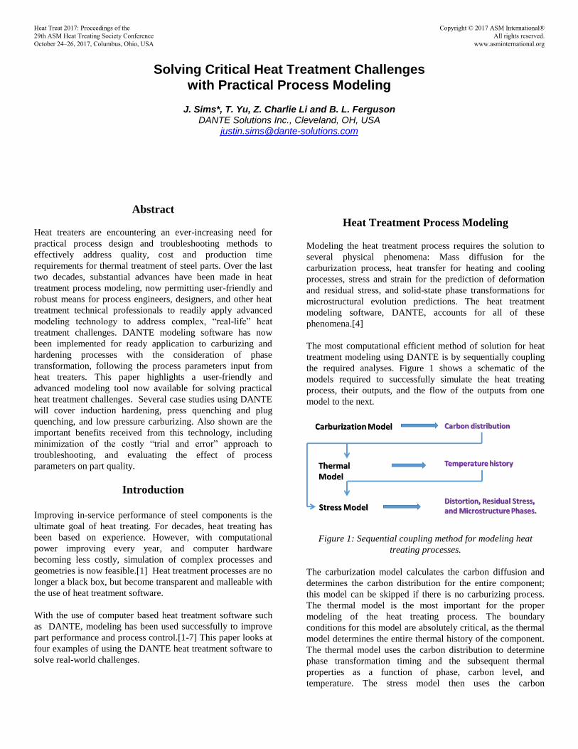
The most computational efficient method of solution for heat
treatment modeling using DANTE is by sequentially coupling
the required analyses. Figure 1 shows a schematic of the
models required to successfully simulate the heat treating
process, their outputs, and the flow of the outputs from one
model to the next.
Figure 1: Sequential coupling method for modeling heat
treating processes.
The carburization model calculates the carbon diffusion and
determines the carbon distribution for the entire component;
this model can be skipped if there is no carburizing process.
The thermal model is the most important for the proper
modeling of the heat treating process. The boundary
conditions for this model are absolutely critical, as the thermal
model determines the entire thermal history of the component.
The thermal model uses the carbon distribution to determine
phase transformation timing and the subsequent thermal
properties as a function of phase, carbon level, and
temperature. The stress model then uses the carbon
Heat Treat 2017: Proceedings of the 29th ASM Heat Treating Society Conference October 24–26, 2017, Columbus, Ohio, USA
Copyright © 2017 ASM International® All rights reserved.
www.asminternational.org
distribution and the thermal history to calculate the
displacements and stresses in the component throughout the
entire process, including the final distortion and residual stress.
ANSYS Workbench allows for an intuitive approach to the
sequentially coupled method of modeling the heat treating
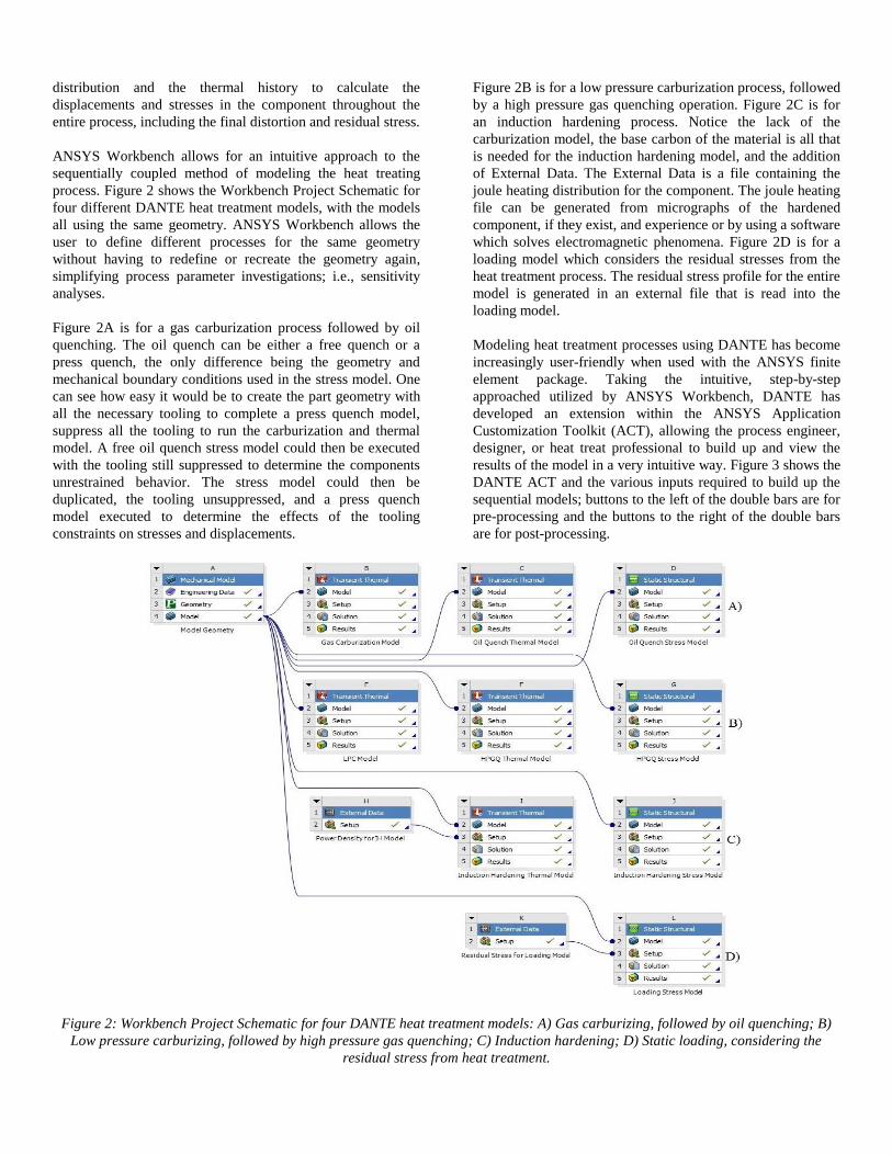
process. Figure 2 shows the Workbench Project Schematic for
four different DANTE heat treatment models, with the models
all using the same geometry. ANSYS Workbench allows the
user to define different processes for the same geometry
without having to redefine or recreate the geometry again,
simplifying process parameter investigations; i.e., sensitivity
analyses.
Figure 2A is for a gas carburization process followed by oil
quenching. The oil quench can be either a free quench or a
press quench, the only difference being the geometry and
mechanical boundary conditions used in the stress model. One
can see how easy it would be to create the part geometry with
all the necessary tooling to complete a press quench model,
suppress all the tooling to run the carburization and thermal
model. A free oil quench stress model could then be executed
with the tooling still suppressed to determine the components
unrestrained behavior. The stress model could then be
duplicated, the tooling unsuppressed, and a press quench
model executed to determine the effects of the tooling
constraints on stresses and displacements.
Figure 2B is for a low pressure carburization process, followed
by a high pressure gas quenching operation. Figure 2C is for
an induction hardening process. Notice the lack of the
carburization model, the base carbon of the material is all that
is needed for the induction hardening model, and the addition
of External Data. The External Data is a file containing the
joule heating distribution for the component. The joule heating
file can be generated from micrographs of the hardened
component, if they exist, and experience or by using a software
which solves electromagnetic phenomena. Figure 2D is for a
loading model which considers the residual stresses from the
heat treatment process. The residual stress profile for the entire
model is generated in an external file that is read into the
loading model.
Modeling heat treatment processes using DANTE has become
increasingly user-friendly when used with the ANSYS finite
element package. Taking the intuitive, step-by-step
approached utilized by ANSYS Workbench, DANTE has
developed an extension within the ANSYS Application
Customization Toolkit (ACT), allowing the process engineer,
designer, or heat treat professional to build up and view the
results of the model in a very intuitive way. Figure 3 shows the
DANTE ACT and the various inputs required to build up the
sequential models; buttons to the left of the double bars are for
pre-processing and the buttons to the right of the double bars
are for post-processing.
Figure 2: Workbench Project Schematic for four DANTE heat treatment models: A) Gas carburizing, followed by oil quenching; B)
Low pressure carburizing, followed by high pressure gas quenching; C) Induction hardening; D) Static loading, considering the
residual stress from heat treatment.
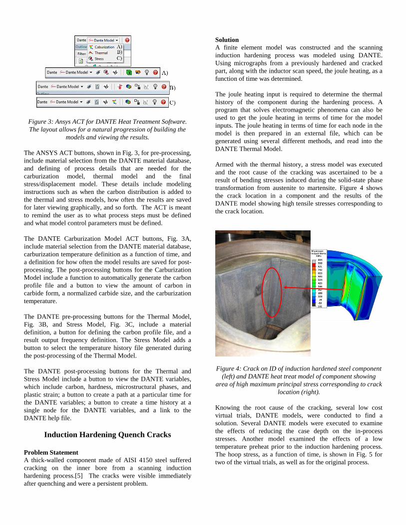
Figure 3: Ansys ACT for DANTE Heat Treatment Software.
The layout allows for a natural progression of building the
models and viewing the results.
The ANSYS ACT buttons, shown in Fig. 3, for pre-processing,
include material selection from the DANTE material database,
and defining of process details that are needed for the
carburization model, thermal model and the final
stress/displacement model. These details include modeling
instructions such as when the carbon distribution is added to
the thermal and stress models, how often the results are saved
for later viewing graphically, and so forth. The ACT is meant
to remind the user as to what process steps must be defined
and what model control parameters must be defined.
The DANTE Carburization Model ACT buttons, Fig. 3A,
include material selection from the DANTE material database,
carburization temperature definition as a function of time, and
a definition for how often the model results are saved for post-
processing. The post-processing buttons for the Carburization
Model include a function to automatically generate the carbon
profile file and a button to view the amount of carbon in
carbide form, a normalized carbide size, and the carburization
temperature.
The DANTE pre-processing buttons for the Thermal Model,
Fig. 3B, and Stress Model, Fig. 3C, include a material
definition, a button for defining the carbon profile file, and a
result output frequency definition. The Stress Model adds a
button to select the temperature history file generated during
the post-processing of the Thermal Model.
The DANTE post-processing buttons for the Thermal and
Stress Model include a button to view the DANTE variables,
which include carbon, hardness, microstructural phases, and
plastic strain; a button to create a path at a particular time for
the DANTE variables; a button to create a time history at a
single node for the DANTE variables, and a link to the
DANTE help file.
Induction Hardening Quench Cracks
Problem Statement
A thick-walled component made of AISI 4150 steel suffered
cracking on the inner bore from a scanning induction
hardening process.[5] The cracks were visible immediately
after quenching and were a persistent problem.
Solution
A finite element model was constructed and the scanning
induction hardening process was modeled using DANTE.
Using micrographs from a previously hardened and cracked
part, along with the inductor scan speed, the joule heating, as a
function of time was determined.
The joule heating input is required to determine the thermal
history of the component during the hardening process. A
program that solves electromagnetic phenomena can also be
used to get the joule heating in terms of time for the model
inputs. The joule heating in terms of time for each node in the
model is then prepared in an external file, which can be
generated using several different methods, and read into the
DANTE Thermal Model.
Armed with the thermal history, a stress model was executed
and the root cause of the cracking was ascertained to be a
result of bending stresses induced during the solid-state phase
transformation from austenite to martensite. Figure 4 shows
the crack location in a component and the results of the
DANTE model showing high tensile stresses corresponding to
the crack location.
Figure 4: Crack on ID of induction hardened steel component
(left) and DANTE heat treat model of component showing
area of high maximum principal stress corresponding to crack
location (right).
Knowing the root cause of the cracking, several low cost
virtual trials, DANTE models, were conducted to find a
solution. Several DANTE models were executed to examine
the effects of reducing the case depth on the in-process
stresses. Another model examined the effects of a low
temperature preheat prior to the induction hardening process.
The hoop stress, as a function of time, is shown in Fig. 5 for
two of the virtual trials, as well as for the original process.
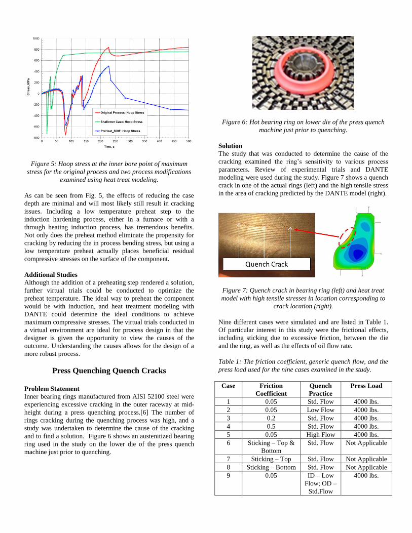
Figure 5: Hoop stress at the inner bore point of maximum
stress for the original process and two process modifications
examined using heat treat modeling.
As can be seen from Fig. 5, the effects of reducing the case
depth are minimal and will most likely still result in cracking
issues. Including a low temperature preheat step to the
induction hardening process, either in a furnace or with a
through heating induction process, has tremendous benefits.
Not only does the preheat method eliminate the propensity for
cracking by reducing the in process bending stress, but using a
low temperature preheat actually places beneficial residual
compressive stresses on the surface of the component.
Additional Studies
Although the addition of a preheating step rendered a solution,
further virtual trials could be conducted to optimize the
preheat temperature. The ideal way to preheat the component
would be with induction, and heat treatment modeling with
DANTE could determine the ideal conditions to achieve
maximum compressive stresses. The virtual trials conducted in
a virtual environment are ideal for process design in that the
designer is given the opportunity to view the causes of the
outcome. Understanding the causes allows for the design of a
more robust process.
Press Quenching Quench Cracks
Problem Statement
Inner bearing rings manufactured from AISI 52100 steel were
experiencing excessive cracking in the outer raceway at mid-
height during a press quenching process.[6] The number of
rings cracking during the quenching process was high, and a
study was undertaken to determine the cause of the cracking
and to find a solution. Figure 6 shows an austenitized bearing
ring used in the study on the lower die of the press quench
machine just prior to quenching.
Figure 6: Hot bearing ring on lower die of the press quench
machine just prior to quenching.
Solution
The study that was conducted to determine the cause of the
cracking examined the ring’s sensitivity to various process
parameters. Review of experimental trials and DANTE
modeling were used during the study. Figure 7 shows a quench
crack in one of the actual rings (left) and the high tensile stress
in the area of cracking predicted by the DANTE model (right).
Figure 7: Quench crack in bearing ring (left) and heat treat
model with high tensile stresses in location corresponding to
crack location (right).
Nine different cases were simulated and are listed in Table 1.
Of particular interest in this study were the frictional effects,
including sticking due to excessive friction, between the die
and the ring, as well as the effects of oil flow rate.
Table 1: The friction coefficient, generic quench flow, and the
press load used for the nine cases examined in the study.
Case Friction
Coefficient
Quench
Practice
Press Load
1 0.05 Std. Flow 4000 lbs.
2 0.05 Low Flow 4000 lbs.
3 0.2 Std. Flow 4000 lbs.
4 0.5 Std. Flow 4000 lbs.
5 0.05 High Flow 4000 lbs.
6 Sticking – Top &
Bottom
Std. Flow Not Applicable
7 Sticking – Top Std. Flow Not Applicable
8 Sticking – Bottom Std. Flow Not Applicable
9 0.05 ID – Low
Flow; OD –
Std.Flow
4000 lbs.
Frictional effects were considered by using a friction
coefficient at the boundary between the ring and the press
quench tooling. Sticking of the ring to the die, as a result of
increased friction, was modeled by fixing the top surface,
bottom surface, or top and bottom surface nodes on the ring
which were in contact with the die. The interaction between
the top and bottom dies with the corresponding ring surfaces
were of the most concern, due to the restriction created by
friction as the ring contracted and expanded during the
quenching process due to thermal and phase transformation
effects, respectively.
The effects of flow rates on the in-process and residual stresses
near the area corresponding to the crack location were also of
interest and modeled for this study. The Standard (Std.) Flow
rate was the flow rate being used at the time of the study, with
the High Flow and Low Flow simply multiples of the Std.
Flow, as shown in Table 1.
Table 2 shows the maximum axial stress occurring in the
bearing ring during the process and the final maximum
residual axial stress predicted by the DANTE models for all 9
cases examined during the study.
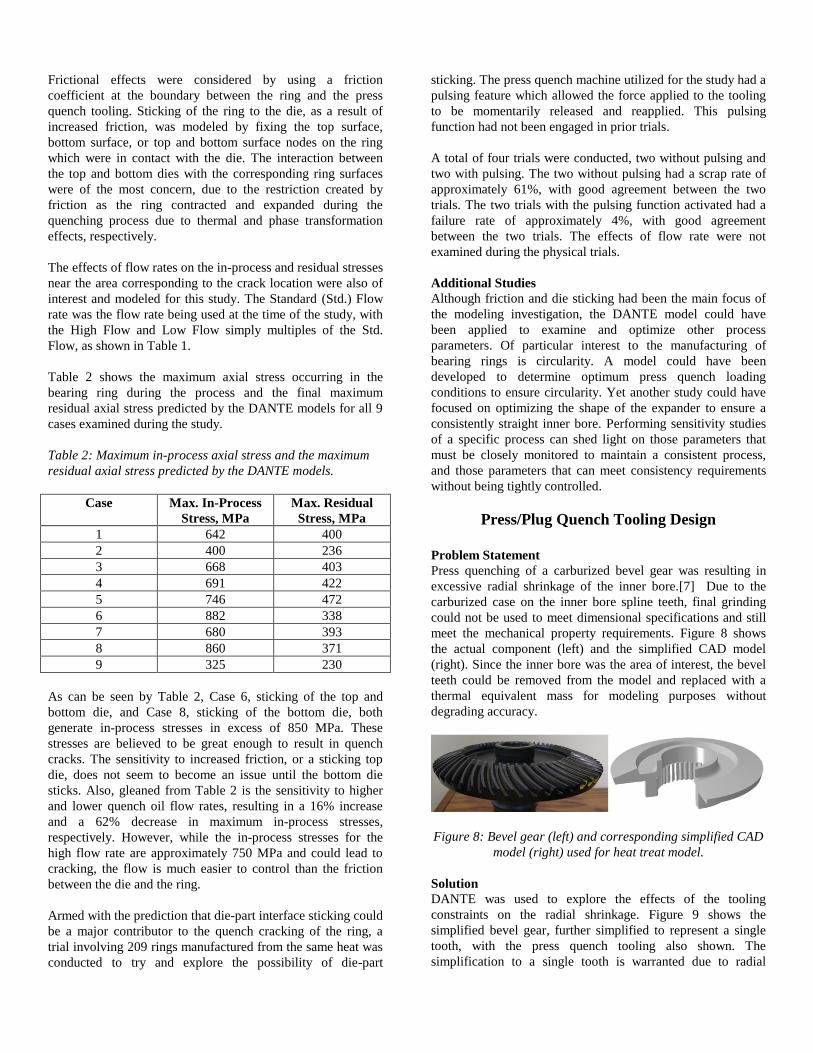
Table 2: Maximum in-process axial stress and the maximum
residual axial stress predicted by the DANTE models.
Case Max. In-Process
Stress, MPa
Max. Residual
Stress, MPa
1 642 400
2 400 236
3 668 403
4 691 422
5 746 472
6 882 338
7 680 393
8 860 371
9 325 230
As can be seen by Table 2, Case 6, sticking of the top and
bottom die, and Case 8, sticking of the bottom die, both
generate in-process stresses in excess of 850 MPa. These
stresses are believed to be great enough to result in quench
cracks. The sensitivity to increased friction, or a sticking top
die, does not seem to become an issue until the bottom die
sticks. Also, gleaned from Table 2 is the sensitivity to higher
and lower quench oil flow rates, resulting in a 16% increase
and a 62% decrease in maximum in-process stresses,
respectively. However, while the in-process stresses for the
high flow rate are approximately 750 MPa and could lead to
cracking, the flow is much easier to control than the friction
between the die and the ring.
Armed with the prediction that die-part interface sticking could
be a major contributor to the quench cracking of the ring, a
trial involving 209 rings manufactured from the same heat was
conducted to try and explore the possibility of die-part
sticking. The press quench machine utilized for the study had a
pulsing feature which allowed the force applied to the tooling
to be momentarily released and reapplied. This pulsing
function had not been engaged in prior trials.
A total of four trials were conducted, two without pulsing and
two with pulsing. The two without pulsing had a scrap rate of
approximately 61%, with good agreement between the two
trials. The two trials with the pulsing function activated had a
failure rate of approximately 4%, with good agreement
between the two trials. The effects of flow rate were not
examined during the physical trials.
Additional Studies
Although friction and die sticking had been the main focus of
the modeling investigation, the DANTE model could have
been applied to examine and optimize other process
parameters. Of particular interest to the manufacturing of
bearing rings is circularity. A model could have been
developed to determine optimum press quench loading
conditions to ensure circularity. Yet another study could have
focused on optimizing the shape of the expander to ensure a
consistently straight inner bore. Performing sensitivity studies
of a specific process can shed light on those parameters that
must be closely monitored to maintain a consistent process,
and those parameters that can meet consistency requirements
without being tightly controlled.
Press/Plug Quench Tooling Design
Problem Statement
Press quenching of a carburized bevel gear was resulting in
excessive radial shrinkage of the inner bore.[7] Due to the
carburized case on the inner bore spline teeth, final grinding
could not be used to meet dimensional specifications and still
meet the mechanical property requirements. Figure 8 shows
the actual component (left) and the simplified CAD model
(right). Since the inner bore was the area of interest, the bevel
teeth could be removed from the model and replaced with a
thermal equivalent mass for modeling purposes without
degrading accuracy.
Figure 8: Bevel gear (left) and corresponding simplified CAD
model (right) used for heat treat model.
Solution
DANTE was used to explore the effects of the tooling
constraints on the radial shrinkage. Figure 9 shows the
simplified bevel gear, further simplified to represent a single
tooth, with the press quench tooling also shown. The
simplification to a single tooth is warranted due to radial
shrinkage being the primary concern; out-of-round distortion is
not considered and was not an issue. The assumptions of cyclic
symmetry and uniform cooling in the circumferential direction
form the basis of the single tooth model.
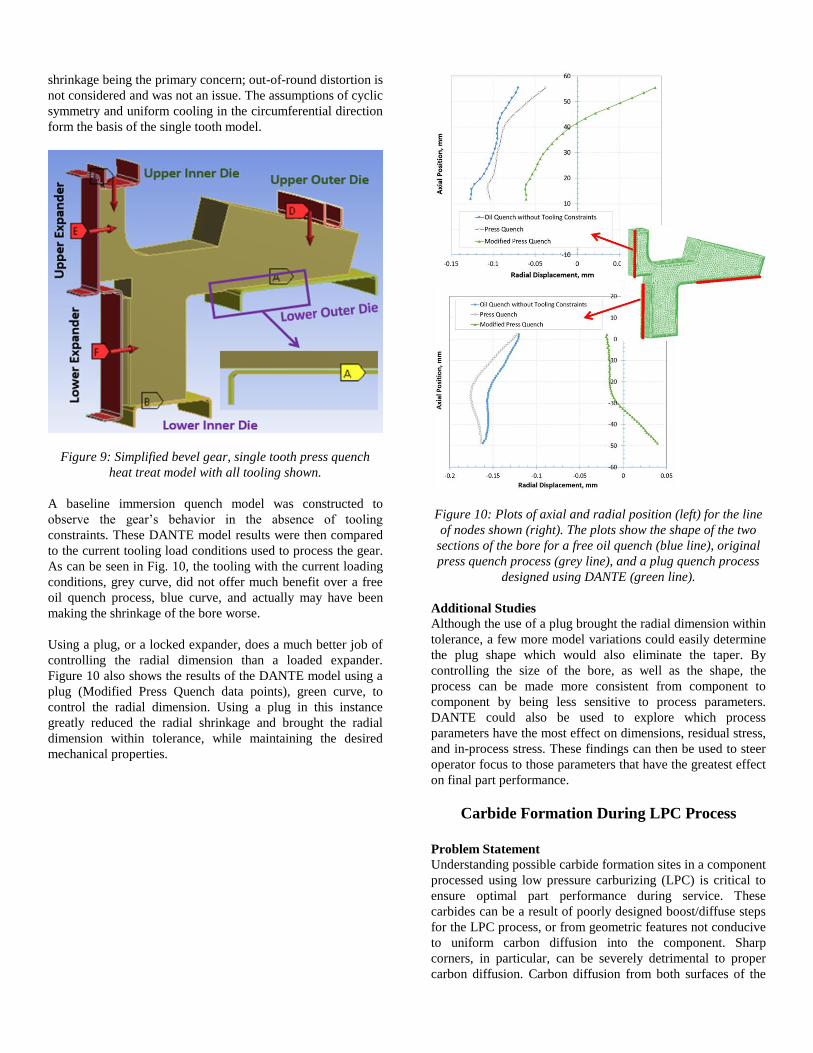
Figure 9: Simplified bevel gear, single tooth press quench
heat treat model with all tooling shown.
A baseline immersion quench model was constructed to
observe the gear’s behavior in the absence of tooling
constraints. These DANTE model results were then compared
to the current tooling load conditions used to process the gear.
As can be seen in Fig. 10, the tooling with the current loading
conditions, grey curve, did not offer much benefit over a free
oil quench process, blue curve, and actually may have been
making the shrinkage of the bore worse.
Using a plug, or a locked expander, does a much better job of
controlling the radial dimension than a loaded expander.
Figure 10 also shows the results of the DANTE model using a
plug (Modified Press Quench data points), green curve, to
control the radial dimension. Using a plug in this instance
greatly reduced the radial shrinkage and brought the radial
dimension within tolerance, while maintaining the desired
mechanical properties.
Figure 10: Plots of axial and radial position (left) for the line
of nodes shown (right). The plots show the shape of the two
sections of the bore for a free oil quench (blue line), original
press quench process (grey line), and a plug quench process
designed using DANTE (green line).
Additional Studies
Although the use of a plug brought the radial dimension within
tolerance, a few more model variations could easily determine
the plug shape which would also eliminate the taper. By
controlling the size of the bore, as well as the shape, the
process can be made more consistent from component to
component by being less sensitive to process parameters.
DANTE could also be used to explore which process
parameters have the most effect on dimensions, residual stress,
and in-process stress. These findings can then be used to steer
operator focus to those parameters that have the greatest effect
on final part performance.
Carbide Formation During LPC Process
Problem Statement
Understanding possible carbide formation sites in a component
processed using low pressure carburizing (LPC) is critical to
ensure optimal part performance during service. These
carbides can be a result of poorly designed boost/diffuse steps
for the LPC process, or from geometric features not conducive
to uniform carbon diffusion into the component. Sharp
corners, in particular, can be severely detrimental to proper
carbon diffusion. Carbon diffusion from both surfaces of the
corner can lead to a carbon buildup and a subsequent area of
increased carbide formation. Machining off the areas of
excessive carbide formation can remove the unwanted
microstructure, but can also remove the carburized case that
gives the component the desired mechanical properties.
Solution
Modeling of the LPC process using DANTE can help
understand when geometric features create a strong possibility
to form unwanted carbides. DANTE can also be used to design
the boost/diffuse cycles of the LPC process, but is not
discussed here. These carbides either need to be avoided in the
first place, or their location should be known well enough that
finish machining can remove them without degrading the
mechanical properties of the component.
Using an axisymmetric ring made from X-2M with a 101.6
mm OD and a 12.7 mm wall thickness, an LPC process was
used to achieve a surface carbon value of 1.0% and an ECD of
1.0 mm. The first geometry investigated used sharp corners on
the ID and OD surface. Several plots were generated to show
the amount of carbon within the austenite matrix, the amount
of carbon locked in carbides, and the total amount of carbon.
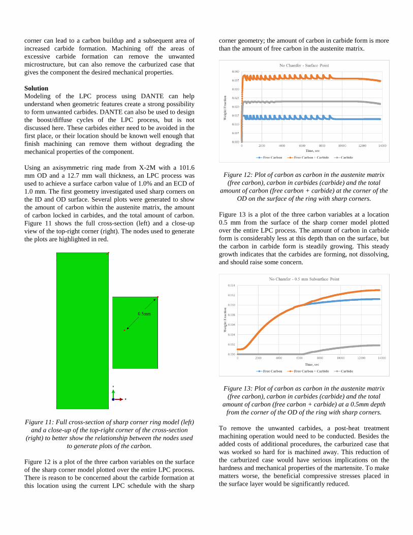
Figure 11 shows the full cross-section (left) and a close-up
view of the top-right corner (right). The nodes used to generate
the plots are highlighted in red.
Figure 11: Full cross-section of sharp corner ring model (left)
and a close-up of the top-right corner of the cross-section
(right) to better show the relationship between the nodes used
to generate plots of the carbon.
Figure 12 is a plot of the three carbon variables on the surface
of the sharp corner model plotted over the entire LPC process.
There is reason to be concerned about the carbide formation at
this location using the current LPC schedule with the sharp
corner geometry; the amount of carbon in carbide form is more
than the amount of free carbon in the austenite matrix.
Figure 12: Plot of carbon as carbon in the austenite matrix
(free carbon), carbon in carbides (carbide) and the total
amount of carbon (free carbon + carbide) at the corner of the
OD on the surface of the ring with sharp corners.
Figure 13 is a plot of the three carbon variables at a location
0.5 mm from the surface of the sharp corner model plotted
over the entire LPC process. The amount of carbon in carbide
form is considerably less at this depth than on the surface, but
the carbon in carbide form is steadily growing. This steady
growth indicates that the carbides are forming, not dissolving,
and should raise some concern.
Figure 13: Plot of carbon as carbon in the austenite matrix
(free carbon), carbon in carbides (carbide) and the total
amount of carbon (free carbon + carbide) at a 0.5mm depth
from the corner of the OD of the ring with sharp corners.
To remove the unwanted carbides, a post-heat treatment
machining operation would need to be conducted. Besides the
added costs of additional procedures, the carburized case that
was worked so hard for is machined away. This reduction of
the carburized case would have serious implications on the
hardness and mechanical properties of the martensite. To make
matters worse, the beneficial compressive stresses placed in
the surface layer would be significantly reduced.
With the ability to thoroughly interrogate the modeling results,
an area can be found where the amount of carbide formation is
acceptable. The area corresponding to this criterion occurs at
0.5 mm from the corner on the OD surface for this geometry.
Figure 14 shows this location with the node highlighted in red
for the full cross-section (left) and a close-up of the top-right
corner (right).
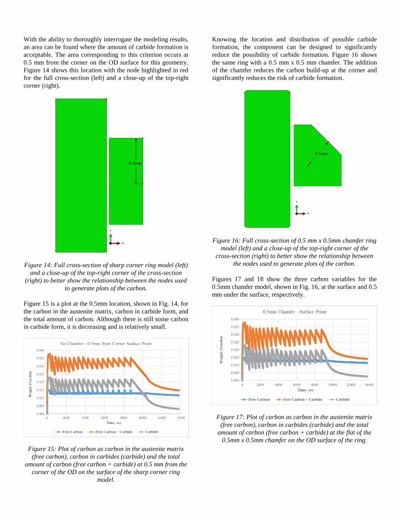
Figure 14: Full cross-section of sharp corner ring model (left)
and a close-up of the top-right corner of the cross-section
(right) to better show the relationship between the nodes used
to generate plots of the carbon.
Figure 15 is a plot at the 0.5mm location, shown in Fig. 14, for
the carbon in the austenite matrix, carbon in carbide form, and
the total amount of carbon. Although there is still some carbon
in carbide form, it is decreasing and is relatively small.
Figure 15: Plot of carbon as carbon in the austenite matrix
(free carbon), carbon in carbides (carbide) and the total
amount of carbon (free carbon + carbide) at 0.5 mm from the
corner of the OD on the surface of the sharp corner ring
model.
Knowing the location and distribution of possible carbide
formation, the component can be designed to significantly
reduce the possibility of carbide formation. Figure 16 shows
the same ring with a 0.5 mm x 0.5 mm chamfer. The addition
of the chamfer reduces the carbon build-up at the corner and
significantly reduces the risk of carbide formation.
Figure 16: Full cross-section of 0.5 mm x 0.5mm chamfer ring
model (left) and a close-up of the top-right corner of the
cross-section (right) to better show the relationship between
the nodes used to generate plots of the carbon.
Figures 17 and 18 show the three carbon variables for the
0.5mm chamfer model, shown in Fig. 16, at the surface and 0.5
mm under the surface, respectively.
Figure 17: Plot of carbon as carbon in the austenite matrix
(free carbon), carbon in carbides (carbide) and the total
amount of carbon (free carbon + carbide) at the flat of the
0.5mm x 0.5mm chamfer on the OD surface of the ring.
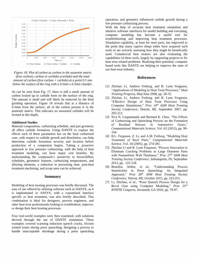
Figure 18: Plot of carbon as carbon in the austenite matrix
(free carbon), carbon in carbides (carbide) and the total
amount of carbon (free carbon + carbide) at a point 0.5 mm
below the surface of the ring with a 0.5mm x 0.5mm chamfer.
As can be seen from Fig. 17, there is still a small amount of
carbon locked up in carbide form on the surface of the ring.
The amount is small and will likely be removed by the final
grinding operation. Figure 18 reveals that at a distance of
0.5mm from the surface, all of the carbon present is in the
austenite matrix. This indicates no unwanted carbides will be
formed at this depth.
Additional Studies
Material composition, carburizing schedule, and part geometry
all affect carbide formation. Using DANTE to explore the
effects each of these parameters has on the final carburized
case, with respect to carbide growth and dissolution, can help
determine carbide formation severity and location before
production of a component begins. Taking a proactive
approach to low pressure carburizing, with the help of heat
treatment modeling, can have major cost benefits. By
understanding the component’s sensitivity to boost/diffuse
schedules, geometric features, carburizing temperatures, and
alloying elements, a reduction in processing time, post-heat
treatment machining, and scrap rates can be achieved.
Summary
Modeling of heat treating processes was briefly discussed. The
ease of use offered by utilizing software such as DANTE, as it
is implemented in ANSYS, with a customized interface
specific to heat treatment, was also briefly described. This
combination is ideal for designers, process engineers, and
other heat treat professionals looking to troubleshoot, improve,
or design their heat treating processes.
Four real-world examples were then examined, with solutions
derived through the use of DANTE simulation. These
examples covered scanning induction quench cracks, friction
related issues during press quenching, designing a process to
handle unacceptable shrinkage during a press quenching
operation, and geometry influenced carbide growth during a
low pressure carburizing process.
With the help of accurate heat treatment simulation and
intuitive software interfaces for model building and executing,
computer modeling has become a useful tool for
troubleshooting and improving heat treatment processes.
Simulation capability, at least for steel parts, has improved to
the point that many captive shops either have acquired such
tools or are actively assessing how they might be beneficially
used. Commercial heat treaters are also evaluating the
capabilities of these tools, largely by supporting projects to fix
heat treat related problems. Realizing their potential, computer
based tools like DANTE are helping to improve the state of
our heat treat industry.
References
[1] Zhichao Li, Andrew Freborg, and B. Lynn Ferguson,
“Applications of Modeling to Heat Treat Processes,” Heat
Treating Progress, May/June 2008, pp. 28-33.
[2] Zhichao Li, Andrew Freborg, and B. Lynn Ferguson,
“Effective Design of Heat Treat Processes Using
Computer Simulations,” Proc 24th ASM Heat Treating
Society Conference, Detroit, MI, September 2007, pp.
205-213.
[3] Siva N. Lingamanaik and Bernard K. Chen, “The Effects
of Carburising and Quenching Process on the Formation
of Residual Stresses in Automotive Gears,”
Computational Materials Science, Vol. 62 (2012), pp. 99-
104.
[4] B.L. Ferguson, Z. Li, and A.M. Freborg, “Modeling Heat
Treatment of Steel Parts,” Computational Materials
Science, Vol. 34 (2005), pp. 274-281.
[5] Zhichao Li and B. Lynn Ferguson, “Process Innovation to
Eliminate Cracking Problems in Large Diameter Parts
with Nonuniform Wall Thickness,” Proc 27th ASM Heat
Treating Society Conference, Indianapolis, IN, September
2013, pp. 125-128.
[6] Reardon, Arthur, et al., “Understanding Process
Sensitivities in Press Quenching: An Integrated
Approach,” Proc 28th ASM Heat Treating Society
Conference, Detroit, MI, October 2015, pp. 233-251.
[7] Li, Zhichao, et al., “Press Quench Process Design for a
Bevel Gear using Computer Modeling,” Proc 23rd
IFHTSE Congress, Savannah, GA 2016, pp. 78-87.