some applications related to chapter 11 material: we will see how the kind of basic science we...
TRANSCRIPT

Some applications related to Chapter 11 material:
We will see how the kind of basic science we discussed in Chapter 11 will probably lead to good advances in applied areas such as:
1- Design of efficient solar cell dyes based on charge transfer absorption.
2- Strongly luminescent materials based on the Jahn-Teller effect.
1- Design of efficient solar cell dyes based on charge
transfer absorption
Pt
N
S
N
S
COO- COO-
Pt
N
S
N
S
PO3-PO3-
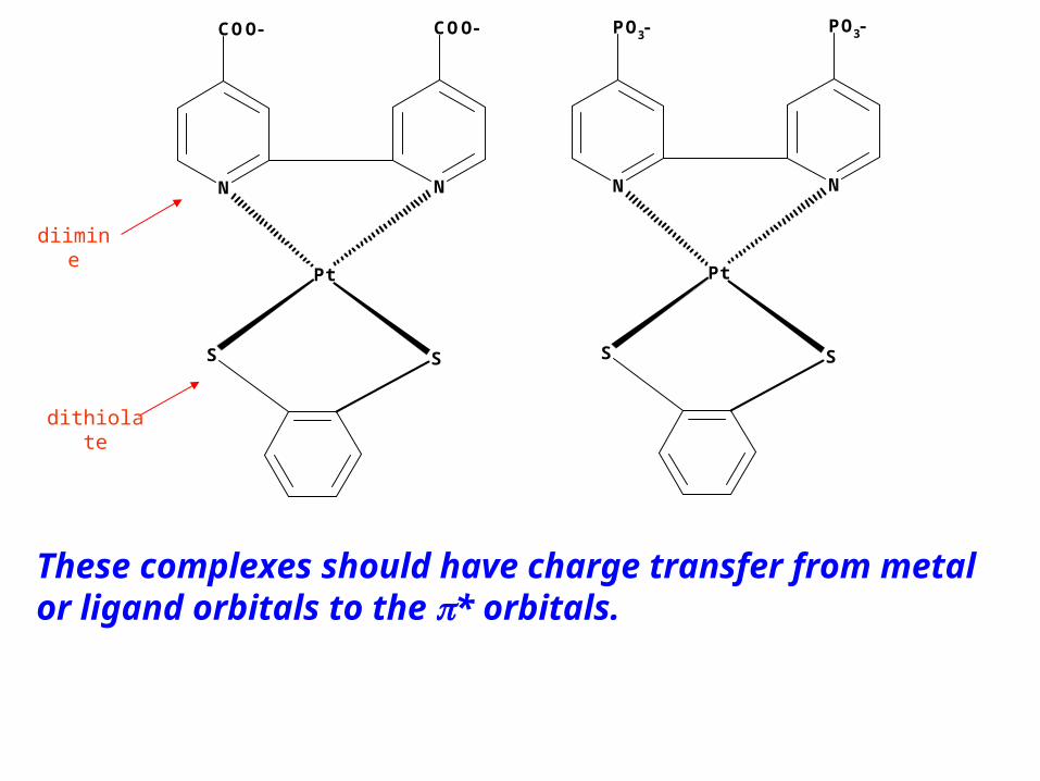
These complexes should have charge transfer from metal or ligand orbitals to the * orbitals.
diimine
dithiolate

CT-band for Pt(dbbpy)tdt
N
N
Pt
S
S
Data from: Cummings, S. D.; Eisenberg, R. J. Am. Chem. Soc. 1996, 118 1949-1960

X- Chloride
Connick W. B.; Fleeman, W. L. Comments on Inorganic Chemistry, 2002, 23, 205-230
X-thiolate
*bpy
dx2-y2
dxz-yz
dxy
dxz+-yz
dz2
bpy
{ (thiolate) +
d (Pt)
CT to diiminehv
0
10,000
20,000
30,000
40,000
50,000
60,000
70,000
200 300 400 500 600 700 800 900 1000 1100 1200 1300 1400 1500 1600
Wavelength, nm
, M
-1cm
-1 (
UV
/VIS
)
0
50
100
150
200
250
300
350
400
450
500
, M
-1cm
-1 (
NIR
)
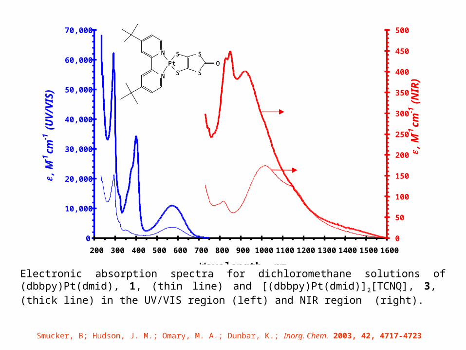
Electronic absorption spectra for dichloromethane solutions of (dbbpy)Pt(dmid), 1, (thin line) and [(dbbpy)Pt(dmid)]2[TCNQ], 3, (thick line) in the UV/VIS region (left) and NIR region (right).
Smucker, B; Hudson, J. M.; Omary, M. A.; Dunbar, K.; Inorg. Chem. 2003, 42, 4717-4723
S
SS
Pt
S
O
N
N S
SS
Pt
S
O
N
N

• So our data for Pt(dbbpy)(dmid) suggest that the lowest-energy absorptions are transitions so the LUMO is dx2-y2
• The literature for Pt(dbbpy)(tdt) and for the M(diimine)(dithiolates) as a class assigns the LUMO to be diimine * instead of dx2-y2
• So is there something magical about dmid that changes the electronic structure from that for analogous complexes with tdt and other dithiolates???
• Or is the difference simply due to an instrumental technicality as Eisenberg and Connick used UV/VIS instruments that only go to 800 nm while we used a UV/VIS/NIR instrument that goes deep into the NIR (down to 3300 nm)?
•Let’s see….. we made Pt(dbbpy)(tdt) !!
N
N
Pt
S
SS
SS
Pt
S
O
N
N S
SS
Pt
S
O
N
N
Pt(dbbpy)(dmid) Pt(dbbpy)(tdt)

0
0.5
1
1.5
2
2.5
200 400 600 800 1000 1200 1400 1600 1800 2000 2200 2400
Wavelength (nm)
Ab
s.
Pt(dbbpy)tdt in CH2Cl2 1cm cell
563nm max solid
563

N
Pt
S
S
N
0
0.1
0.2
0.3
0.4
0.5
0.6
0.7
0.8
200 400 600 800 1000 1200 1400 1600
Wavelength (nm)
Ab
s.
526.5nm max
Pt dbbpy tdt in CH3CN
solid
0
0.1
0.2
0.3
0.4
0.5
0.6
0.7
0.8
0.9
1
250 350 450 550 650 750 850 950 1050
Wavelength (nm)
Ab
s.
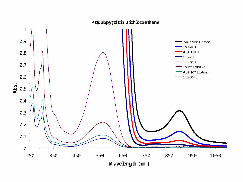
70mg/10mL stock
1ml-2ml
0.5ml-2ml
1:10ml
1:100ml
1mlof 1/100 -2
0.5ml of 1/100-2
1:1000ml
Pt(dbbpy)tdt in Dichloroethane
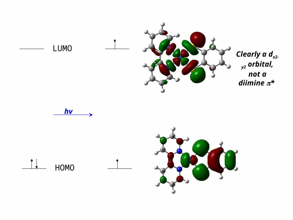
hv
HOMO
LUMOClearly a dx2-y2 orbital, not a diimine *

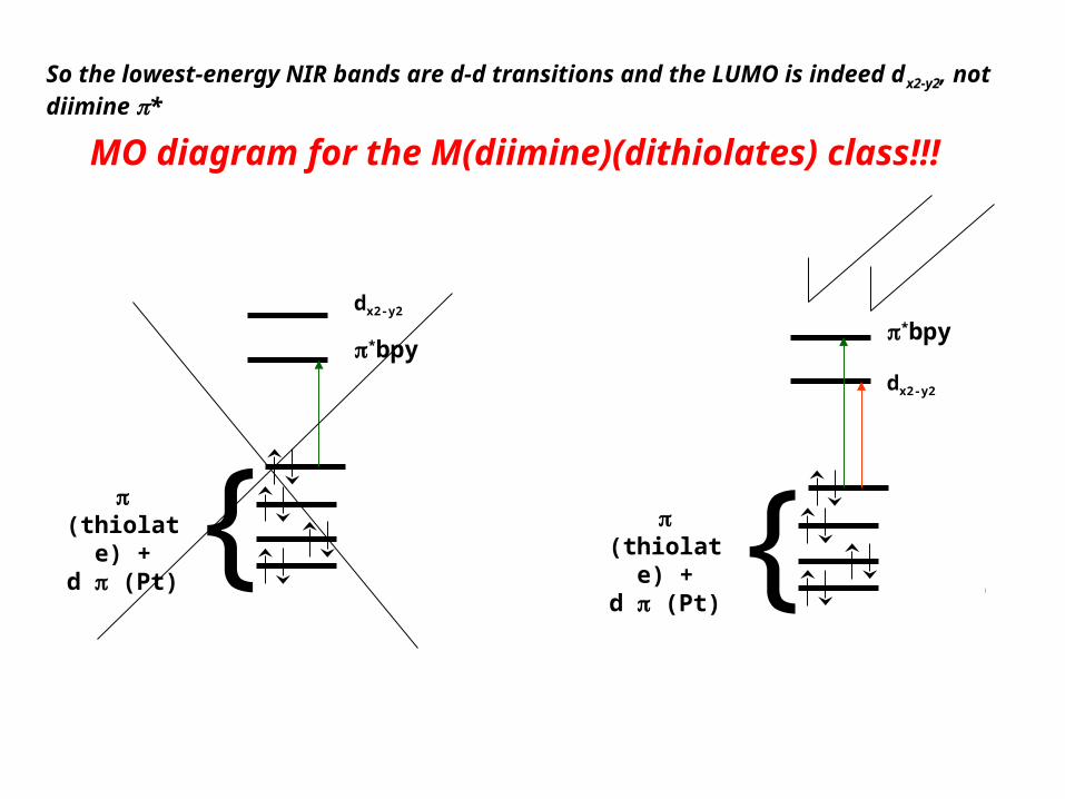
MO diagram for the M(diimine)(dithiolates) class!!!
So the lowest-energy NIR bands are d-d transitions and the LUMO is indeed dx2-y2, not diimine *
*bpy
dx2-y2
dxz-yz
dxy
dxz+-yz
dz2
bpy
{ (thiolate) +
d (Pt)
*bpy
dx2-y2
{ (thiolate) +
d (Pt)

Let’s hear it to Brian Prascher who did the
calculations!!

WHO CARES!!
The above was science, let’s now see a potential application
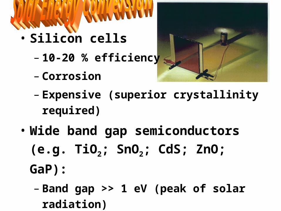
• Silicon cells
– 10-20 % efficiency
– Corrosion
– Expensive (superior crystallinity required)
• Wide band gap semiconductors (e.g. TiO2;
SnO2; CdS; ZnO; GaP):
– Band gap >> 1 eV (peak of solar radiation)
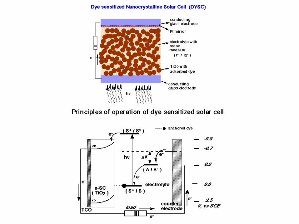
– Solution: tether a dye (absorbs strongly across
the vis into the IR) on the semiconductor
– Cheaper!!… used as colloidal particles
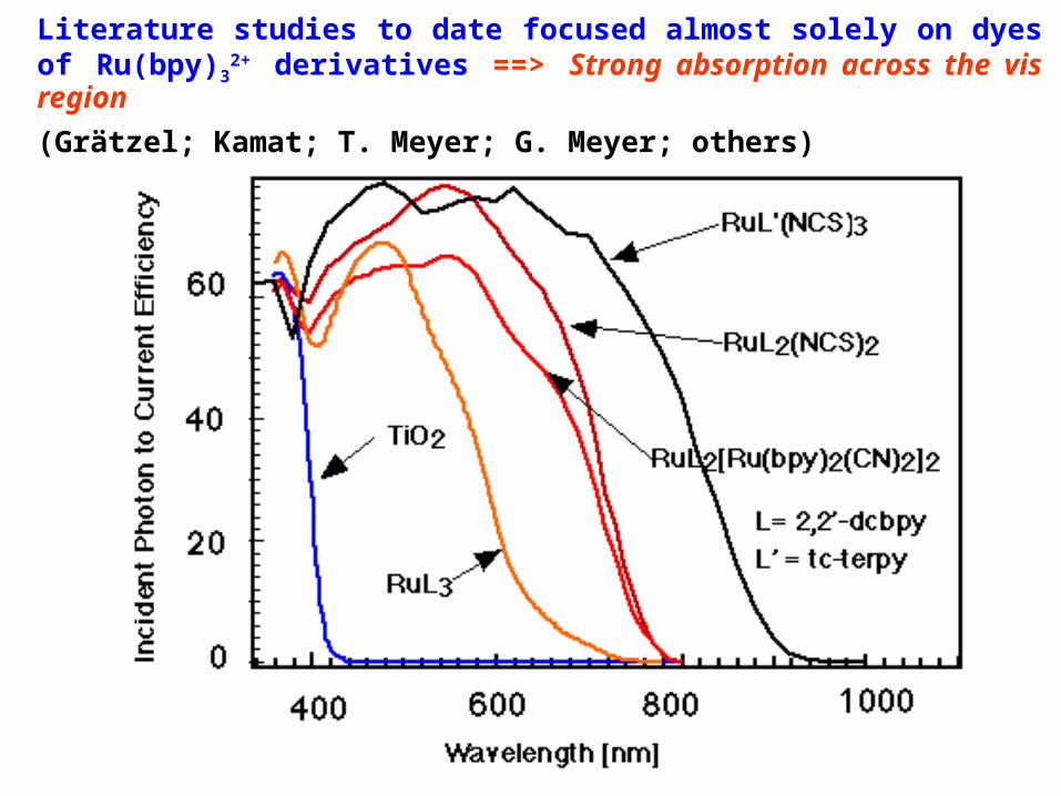
Literature studies to date focused almost solely on dyes of Ru(bpy)32+
derivatives ==> Strong absorption across the vis region
(Grätzel; Kamat; T. Meyer; G. Meyer; others)

Anchoring groups on diimine to allow adsorption on TiO2 surface.
N N
-O3P PO3-
M
SSM
S S
O O
O- -O
N N

solid
Pt dmeobpy tdt
0.18
0.28
0.38
0.48
0.58
0.68
0.78
0.88
0.98
200 300 400 500 600 700 800 900 1000 1100 1200 1300 1400 1500 1600
Wavelenght (nm)
Ab
s.
dmeobpy = (MeOOC)2bpy
Precursor for the carboxylic acid (the ester is easier to handle in organic solvents while the acid is soluble only in aqueous base)

N
Ni
S
S
N
O
O
O
O
0
0.5
1
1.5
2
2.5
3
200 400 600 800 1000 1200 1400 1600 1800 2000
Wavelength (nm)
Ab
s.
0
0.05
0.1
0.15
0.2
0.25
0.3
0.35
0.4
Ni(dmeobpy)tdt in CH2Cl2
Cheaper is better!!

Ni(dcbpy)tdt solid vs Ni(dmeobpy)tdt solid
0
0.2
0.4
0.6
0.8
1
1.2
250 500 750 1000 1250 1500 1750 2000 2250 2500Wavelength (nm)
N
Ni
S
S
N
HO
O
O
HO
We’re testing this as a solar dye in Switzerland
…Stay tuned!!

2- Strongly luminescent materials based on the
Jahn-Teller effect
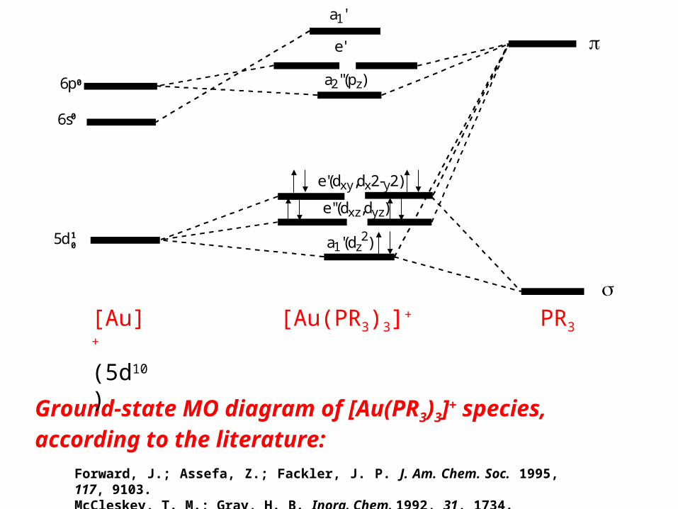
Forward, J.; Assefa, Z.; Fackler, J. P. J. Am. Chem. Soc. 1995, 117, 9103. McCleskey, T. M.; Gray, H. B. Inorg. Chem. 1992, 31, 1734.
Ground-state MO diagram of [Au(PR3)3]+ species, according to the literature:
a1'(dz2)
e''(dxz,dyz)
e'(dxy,dx2-y2)
a2''(pz)
e'
a1'
5d
6s
6p
[Au] +
(5d10) [Au(PR3)3]+ PR3
10
0
0

Molecular orbital diagrams (top) and optimized structures (bottom) for the 1A1’ ground state (left)
of the [Au(PH3)3]+ and its corresponding exciton (right).
Barakat, K. A.; Cundari, T. R.; Omary, M. A. J. Am. Chem. Soc. 2003, 125, 14228-14229
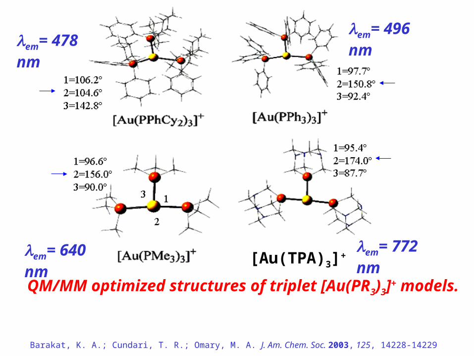
[Au(TPA)3]+
QM/MM optimized structures of triplet [Au(PR3)3]+ models.
em= 478 nm
em= 772 nm em= 640 nm
em= 496 nm
Barakat, K. A.; Cundari, T. R.; Omary, M. A. J. Am. Chem. Soc. 2003, 125, 14228-14229

WHO CARES!!
The above was science, let’s now see a potential application

RGB bright emissions in the solid state and at RT are required for a multi-color device….
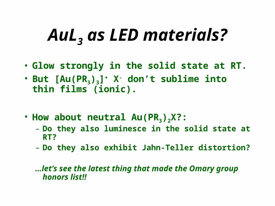
AuL3 as LED materials?
• Glow strongly in the solid state at RT.• But [Au(PR3)3]+ X- don’t sublime into thin films
(ionic).
• How about neutral Au(PR3)2X?:– Do they also luminesce in the solid state at RT?– Do they also exhibit Jahn-Teller distortion?
…let’s see the latest thing that made the Omary group honors list!!

84.7 83.6
191.8
Experiment + Theory makes a good combo!BRAVO PANKAJ!
Omary group honors list, posted 11/22/03
• In a recent paper (Barakat, K. A.; Cundari, T. R.; Omary, M. A. J. Am. Chem. Soc. 2003, 125, 14228-14229), it was discovered that a Jahn-Teller distortion takes place for cationic [AuL3]+ complexes (L=PR3) such that the trigonal geometry changes toward a T-shape in the posphorescent triplet excited state.
• Pankaj shows in the figure above that the same rearrangement toward a T-shape also takes place in the phosphorescent triplet excited state of the neutral Au(PPh3)2Cl complex.
• This result explains the large Stokes’ shift in the experimental spectra on the left.
•We’ll be probing the structure of the excited states of both AuL3 and AuL2X directly by “photocrystallography” and time-resolved EXAFS to verify these calculated structures.
DFT calculations (B3LYP/LANL2DZ) for full model.
• Experimental findings based on the solid-state luminescence spectra at RT shown above:
1- The large Stokes’ shift (11, 200 cm-1), large fwhm (4, 700 cm-1), and the structurless profile all suggest a largely distorted excited state.
2- The lifetime (21.6 ± 0.2 s) suggests that the emission is phosphorescence from a formally triplet excited state.
• To understand the nature of the excited state, Pankaj did full quantum mechanical calculations (DFT) to fully optimize the triplet excited state of the same compound he is studying without any approximation in the model.
200 250 300 350 400 450 500 550 600 650
Wavelength, nm
Inte
nsi
ty, a
rb u
nit
s
Excitation spectrum
max = 320 nm
Emission spectrum
max = 500 nm