some aspects of soil-structure interaction in geotechnical...
TRANSCRIPT
Some Aspects of Soil-Structure Interaction in
Geotechnical Engineering
Ulitsky, V.M. Shashkin, A.G.1
e-mail: [email protected] e-mail: [email protected]
Shashkin, K.G.1 Lisyuk, M.B.1
e-mail: [email protected]
State Transport University Saint Petersburg, Russia1NPO “Georeconstruction”, Saint Petersburg, Russia
ABSTRACT
The paper describes some aspects and applications of soil-structure interaction approach in geotechnical
engineering. Two case histories of deep excavation and historical building analysis are presented.
Indian Geotechnical Conference – 2010, GEOtrendz
December 16–18, 2010
IGS Mumbai Chapter & IIT Bombay
1. INTRODUCTION
New methods of geotechnical analyses using Soil-Structure
Interaction (SSI) approach are becoming increasingly
popular in geotechnical engineering. Now SSI calculations
are successfully used in analysis of highrise building,
underground structures, tunnels, bridges, railways (see, for
example, Brandl & Paulmichl 2006; Katzenbach et al.
2010, Lee et al. 2005, Zdravkovic et al. 2005).
A lot of research in design of foundations with account
of the modern codes was made during the past years
(Bauduin et al. 2005, Fadeev & Lukin 2007, Frank 2006,
and others).
Today the advancement of computation equipment and
technologies creates new opportunities for updating SSI
methods. The main advantage of modern SSI approach is
the ability to combine the latest achievements of soil
mechanics and superstructure calculations.
Many design codes either recommend or directly
prescribe application of soil-structure interaction
calculations (Frank 2006). To fulfill these requirements it is
important to employ the most up-to-date methods of SSI
analysis.
For example, local geotechnical codes in St. Petersburg
require soil-structure interaction analysis under the
following conditions:
– Uneven compressibility of soil underneath foundation
footing with underlying natural subsoil and underneath skin
friction piles;
– Undermining/underexcavation in locations where
subsoil is likely to change its properties owing to
underground construction underneath already constructed
or envisaged objects (metro, large diameter sewer collectors,
underground passages, etc);
– Development of additional settlements caused by
ongoing or envisaged new development in the vicinity, i.e.
in the area of envisaged influence and possible risk (TSN
50-302-2004).
The main advantage of modern SSI calculations is
combining the latest achievements of soil mechanics and
superstructure calculations. This combination can be
provided only through FEM joint modeling of 3D subsoil
and superstructure.
2. MAIN EFFECTS OF SOIL-STRUCTURE
INTERACTION ANALYSES
Main effect of soil-structure interaction behaviour can be
expressed in terms of a redistribution of stresses in subsoil
and forces in superstructure. Differential settlement can
change, compared to calculations with no account of
superstructure stiffness, and structural elements can acquire
new forces due to differential settlements. As a result, the
values of calculated differential settlements face
considerable modification compared to traditional
calculations. Also, some important changes in the design
of a superstructure can be made on the basis of SSI analyses.
Main effects of SSI analysis were presented by authors
elsewhere (Shashkin 2006, Ulitsky et al. 2006, 2006a).
Some details of the main effects of SSI analyses of
different geotechnical problems will be presented in this
paper.
40 V.M. Ulitsky, A.G. Shashkin, K.G. Shashkin and M.B. Lisyuk
3. APPLICATIONS OF SOIL-STRUCTURE
INTERACTION ANALYSES IN DESIGN OF
BUILDINGS. CASE HISTORIES
Over past few years authors developed many design projects
for both historical and new buildings in Saint Petersburg
and Russia. All these projects were successfully completed.
These projects include Konstantinovsky Palace, Mariinsky
Concert Hall, Kamennoostrovsky theater, Stock Exchange
building, largest underground parking in the city on
Komendantsky prospect, many residential and office
buildings.
In design of all these buildings Soil-Structure
interaction approach was used.
4. ANALYSIS OF ST. NICHOLAS NAVAL
CATHEDRAL IN KRONSHTADT TOWN NEAR
SAINT PETERSBURG
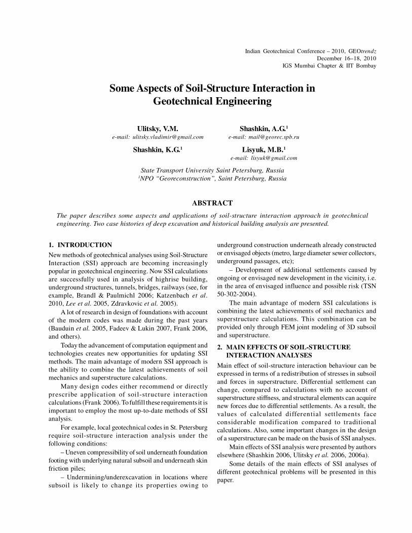
St. Nicholas Naval Cathedral is located in the town of
Kronshtadt (Fig. 1). It was built in 1902-1913 to a design
by V.A.Kossiakoff. The cathedral was designed as a classical
cruciform church with a domed roof. This idea was realized
first in the famous St. Sophia Cathedral in Constantinople.
In fulfilling ancient architectural traditions new
structural materials, introduced in the beginning of the 20
century, were used. The main dome is supported by a system
of steel beams. The dome is made of reinforced concrete.
Four big pillars are the main supporting elements of the
cathedral.
Fig. 1: St. Nicholas Naval Cathedral in Kronshtadt
Site investigations were made in 1897 and 1902.
Eighteen boreholes were provided to the depth of 27.7 m.
The bearing stratum of subsoil is coarse sand with pebbles
(thickness of the stratum is 1.1-4.3. m.). This stratum is
underlain by moraine loams with boulders (thickness 6.4
m) and hard clays.
Due to the presence of boulders the designer decided
to construct foundations of cast-in-place reinforced concrete
avoiding construction of piles.
Immediately after construction differential settlement
was recorded with the value of about 4 cm.
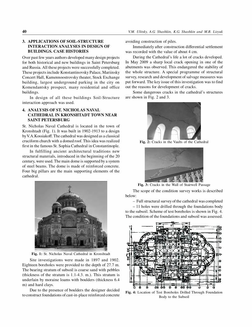
During the Cathedral’s life a lot of cracks developed.
In May 2009 a sharp local crack opening in one of the
abutments was observed. This endangered the stability of
the whole structure. A special programme of structural
survey, research and development of salvage measures was
put forward. The key issue of this investigation was to find
out the reasons for development of cracks.
Some dangerous cracks in the cathedral’s structures
are shown in Fig. 2 and 3.
Fig. 2: Cracks in the Vaults of the Cathedral
Fig. 3: Cracks in the Wall of Stairwell Passage
The scope of the condition survey works is described
below:
– Full structural survey of the cathedral was completed
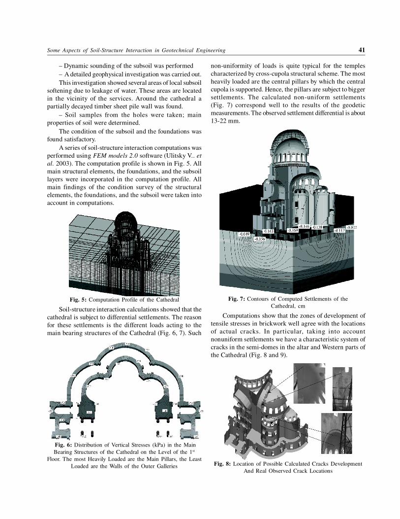
– 11 holes were drilled through the foundations body
to the subsoil. Scheme of test boreholes is shown in Fig. 4.
The condition of the foundations and subsoil was assessed.
Fig. 4: Location of Test Boreholes Drilled Through Foundation
Body to the Subsoil
Some Aspects of Soil-Structure Interaction in Geotechnical Engineering 41
– Dynamic sounding of the subsoil was performed
– A detailed geophysical investigation was carried out.
This investigation showed several areas of local subsoil
softening due to leakage of water. These areas are located
in the vicinity of the services. Around the cathedral a
partially decayed timber sheet pile wall was found.
– Soil samples from the holes were taken; main
properties of soil were determined.
The condition of the subsoil and the foundations was
found satisfactory.
A series of soil-structure interaction computations was
performed using FEM models 2.0 software (Ulitsky V.. et
al. 2003). The computation profile is shown in Fig. 5. All
main structural elements, the foundations, and the subsoil
layers were incorporated in the computation profile. All
main findings of the condition survey of the structural
elements, the foundations, and the subsoil were taken into
account in computations.
Fig. 5: Computation Profile of the Cathedral
Soil-structure interaction calculations showed that the
cathedral is subject to differential settlements. The reason
for these settlements is the different loads acting to the
main bearing structures of the Cathedral (Fig. 6, 7). Such
Fig. 6: Distribution of Vertical Stresses (kPa) in the Main
Bearing Structures of the Cathedral on the Level of the 1st
Floor. The most Heavily Loaded are the Main Pillars, the Least
Loaded are the Walls of the Outer Galleries
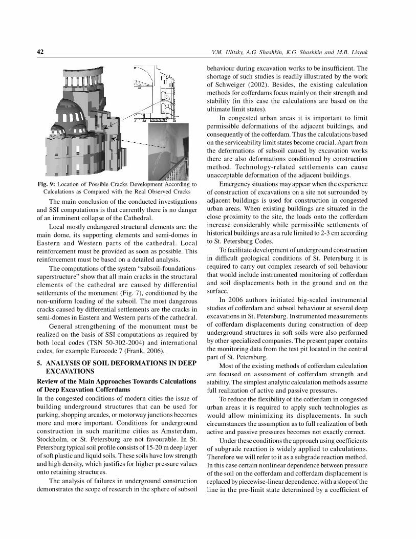
non-uniformity of loads is quite typical for the temples
characterized by cross-cupola structural scheme. The most
heavily loaded are the central pillars by which the central
cupola is supported. Hence, the pillars are subject to bigger
settlements. The calculated non-uniform settlements
(Fig. 7) correspond well to the results of the geodetic
measurements. The observed settlement differential is about
13-22 mm.
Fig. 7: Contours of Computed Settlements of the
Cathedral, cm
Computations show that the zones of development of
tensile stresses in brickwork well agree with the locations
of actual cracks. In particular, taking into account
nonuniform settlements we have a characteristic system of
cracks in the semi-domes in the altar and Western parts of
the Cathedral (Fig. 8 and 9).
Fig. 8: Location of Possible Calculated Cracks Development
And Real Observed Crack Locations
42 V.M. Ulitsky, A.G. Shashkin, K.G. Shashkin and M.B. Lisyuk
Fig. 9: Location of Possible Cracks Development According to
Calculations as Compared with the Real Observed Cracks
The main conclusion of the conducted investigations
and SSI computations is that currently there is no danger
of an imminent collapse of the Cathedral.
Local mostly endangered structural elements are: the
main dome, its supporting elements and semi-domes in
Eastern and Western parts of the cathedral. Local
reinforcement must be provided as soon as possible. This
reinforcement must be based on a detailed analysis.
The computations of the system “subsoil-foundations-
superstructure” show that all main cracks in the structural
elements of the cathedral are caused by differential
settlements of the monument (Fig. 7), conditioned by the
non-uniform loading of the subsoil. The most dangerous
cracks caused by differential settlements are the cracks in
semi-domes in Eastern and Western parts of the cathedral.
General strengthening of the monument must be
realized on the basis of SSI computations as required by
both local codes (TSN 50-302-2004) and international
codes, for example Eurocode 7 (Frank, 2006).
5. ANALYSIS OF SOIL DEFORMATIONS IN DEEP
EXCAVATIONS
Review of the Main Approaches Towards Calculations
of Deep Excavation Cofferdams
In the congested conditions of modern cities the issue of
building underground structures that can be used for
parking, shopping arcades, or motorway junctions becomes
more and more important. Conditions for underground
construction in such maritime cities as Amsterdam,
Stockholm, or St. Petersburg are not favourable. In St.
Petersburg typical soil profile consists of 15-20 m deep layer
of soft plastic and liquid soils. These soils have low strength
and high density, which justifies for higher pressure values
onto retaining structures.
The analysis of failures in underground construction
demonstrates the scope of research in the sphere of subsoil
behaviour during excavation works to be insufficient. The
shortage of such studies is readily illustrated by the work
of Schweiger (2002). Besides, the existing calculation
methods for cofferdams focus mainly on their strength and
stability (in this case the calculations are based on the
ultimate limit states).
In congested urban areas it is important to limit
permissible deformations of the adjacent buildings, and
consequently of the cofferdam. Thus the calculations based
on the serviceability limit states become crucial. Apart from
the deformations of subsoil caused by excavation works
there are also deformations conditioned by construction
method. Technology-related settlements can cause
unacceptable deformation of the adjacent buildings.
Emergency situations may appear when the experience
of construction of excavations on a site not surrounded by
adjacent buildings is used for construction in congested
urban areas. When existing buildings are situated in the
close proximity to the site, the loads onto the cofferdam
increase considerably while permissible settlements of
historical buildings are as a rule limited to 2-3 cm according
to St. Petersburg Codes.
To facilitate development of underground construction
in difficult geological conditions of St. Petersburg it is
required to carry out complex research of soil behaviour
that would include instrumented monitoring of cofferdam
and soil displacements both in the ground and on the
surface.
In 2006 authors initiated big-scaled instrumental
studies of cofferdam and subsoil behaviour at several deep
excavations in St. Petersburg. Instrumented measurements
of cofferdam displacements during construction of deep
underground structures in soft soils were also performed
by other specialized companies. The present paper contains
the monitoring data from the test pit located in the central
part of St. Petersburg.
Most of the existing methods of cofferdam calculation
are focused on assessment of cofferdam strength and
stability. The simplest analytic calculation methods assume
full realization of active and passive pressures.
To reduce the flexibility of the cofferdam in congested
urban areas it is required to apply such technologies as
would allow minimizing its displacements. In such
circumstances the assumption as to full realization of both
active and passive pressures becomes not exactly correct.
Under these conditions the approach using coefficients
of subgrade reaction is widely applied to calculations.
Therefore we will refer to it as a subgrade reaction method.
In this case certain nonlinear dependence between pressure
of the soil on the cofferdam and cofferdam displacement is
replaced by piecewise-linear dependence, with a slope of the
line in the pre-limit state determined by a coefficient of
Some Aspects of Soil-Structure Interaction in Geotechnical Engineering 43
subgrade reaction. The main disadvantage of this approach
is the uncertainty of values of the subgrade reaction coefficient
Kh. Determination of coefficients encounters difficulties, in
this connection a range of empirical formulae exists. In
particular, Schmitt formula can be used (Schmitt, 1995):
3/1
3/4
1.2EI
EK oed
h = (1)
where Eoed
is constrained deformation modulus, E – Young
modulus, I – moment of inertia.
Another drawback of the subgrade reaction method is
the lack of possibility to predict the movement of subsoil.
To overcome the shortcomings of this method of calculation
it is possible to use an elasto-plastic model with a strength
criterion, described by Mohr-Coulomb equation. This model
was also realized in many local and international software
products.
Application of this model may sometimes lead to
erroneous results. In this model soil behaviour both at the
stage of loading and unloading is described by the same
deformation modulus, which does not correspond to the
real soil behaviour. When modelling excavations in soft
soils, the model predicts abnormal uplift of the excavation
bottom which leads to a distortion of the overall deformation
picture. Instead of ground settlement outside the excavation
within a considerable area, it shows uplift of the surface
(see Fig. 15, 16).
When modelling the movements of the subsoil of the
underground structure the most important thing is to define
soil deformations during the unloading phase and
deformations of form change that occur when stress deviator
increases. Hence, in compression test results closer attention
should be paid to unloading curve. In case of clay soils
with a low seepage ratio it would be prudent to carry out
undrained triaxial test, because the time of excavation is
not enough for consolidation to occur. The soil model should
be able to describe soil behaviour during the unloading
phase and non-linear behaviour of the soil when the stress
deviator increases. To meet these requirements it is
necessary to use more complicated soil models, accounting
for soil form change deformations.
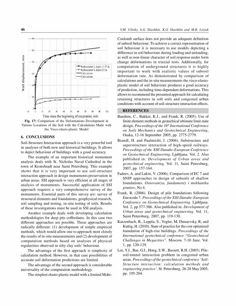
In reality deformations of cofferdam and of soil mass
develop over a time (see Fig. 17). When excavation for
underground structures is carried out in stages, the
deformations often are not stabilised during the undergoing
works of each stage. To give the actual values of movements
the model should take into account a possibility of
incomplete deformation realization on each stage. The
model should include rheological parameters that describe
the development of deformations in time. In many models
the delay in time of deformations of form change is either
not described at all (the deformation of form change is
considered to be instantaneous), or is connected to
consolidation and volume creep through the effect of
dilatancy or contraction. Shear creep of soil should be taken
into accounts.
In Russia geotechnical researchers traditionally give
prominence to the issue of shear creep (Maslov 1977, Vyalov
1978). To describe the deformation of clay soils a visco-
elasto-plastic model was proposed (Shashkin 2006) which
accounts for deformation development in time in terms of
shear creep.
Definition of the Parameters of the Visco-Elasto-
Plastic Model
Majority of the parameters of the model may be determined
through results of standard oedometric and triaxial tests.
The biggest challenge is to set rheological parameters
of the soil. Clay soils that are typical for St. Petersburg
demonstrate clearly pronounced thixotropic properties.
When their natural structure is disturbed they can transform
from solid to liquid state. And as the result the soil viscosity
considerably decreases (by several orders of magnitude).
In the process of coring the natural structure of the samples
is disturbed to a certain degree. Hence, during the laboratory
tests considerable deformations of the samples develop
within several minutes. In reality deformations of structures
appear within rather a long period (ranging from several
days to several months or years).
To test in-situ properties of soils, samples were taken
while excavating the test pits. The samples were directly
placed in the rings for corresponding tests which ensured
the minimal disturbance of their natural structure. During
the triaxial tests the samples of liquid consistency exhibited
a brittle failure pattern at vertical deformation of 5-7%,
(the samples from boreholes exhibited yield without failure
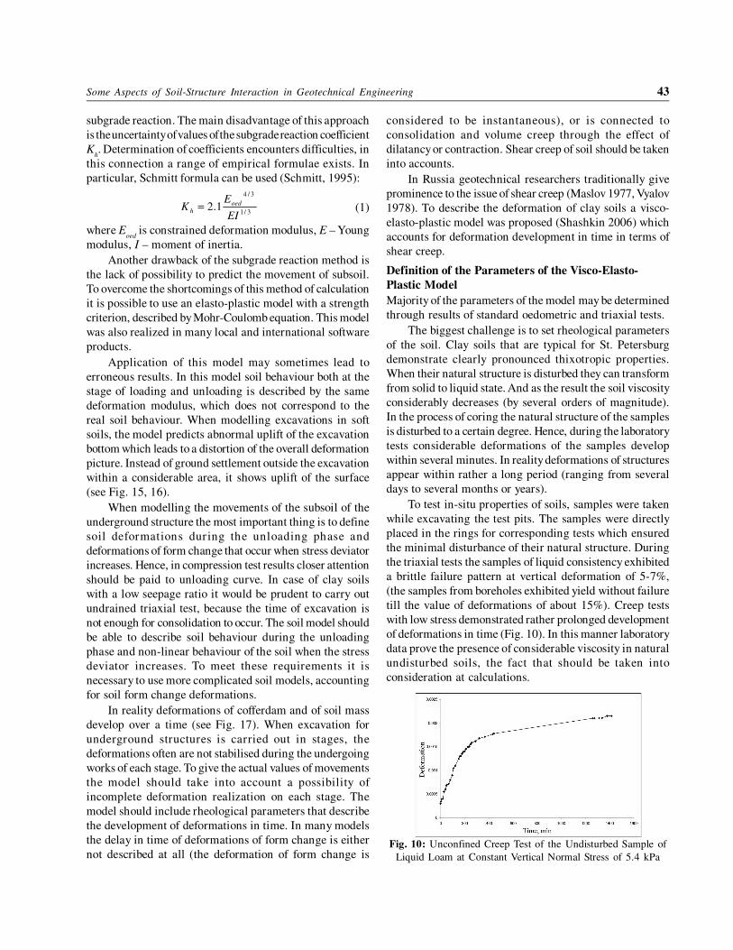
till the value of deformations of about 15%). Creep tests
with low stress demonstrated rather prolonged development
of deformations in time (Fig. 10). In this manner laboratory
data prove the presence of considerable viscosity in natural
undisturbed soils, the fact that should be taken into
consideration at calculations.
Fig. 10: Unconfined Creep Test of the Undisturbed Sample of
Liquid Loam at Constant Vertical Normal Stress of 5.4 kPa
44 V.M. Ulitsky, A.G. Shashkin, K.G. Shashkin and M.B. Lisyuk
To derive rheological parameters for deformation of
form change back analysis of the monitoring data of
deformations of buildings and structures was used. The first
information about the viscosity values local soils was
obtained from the monitoring of deformations of the dyke
structures. It was then adjusted based on the collected data
of monitoring of the settlements of 15 buildings in St.
Petersburg (Shashkin et al., 2007). Subsequent adjustment
was made based on monitoring of underground works at
the test pit.
Comparison of the Calculation Results with the Data
of Instrumented Monitoring at the Test Pit
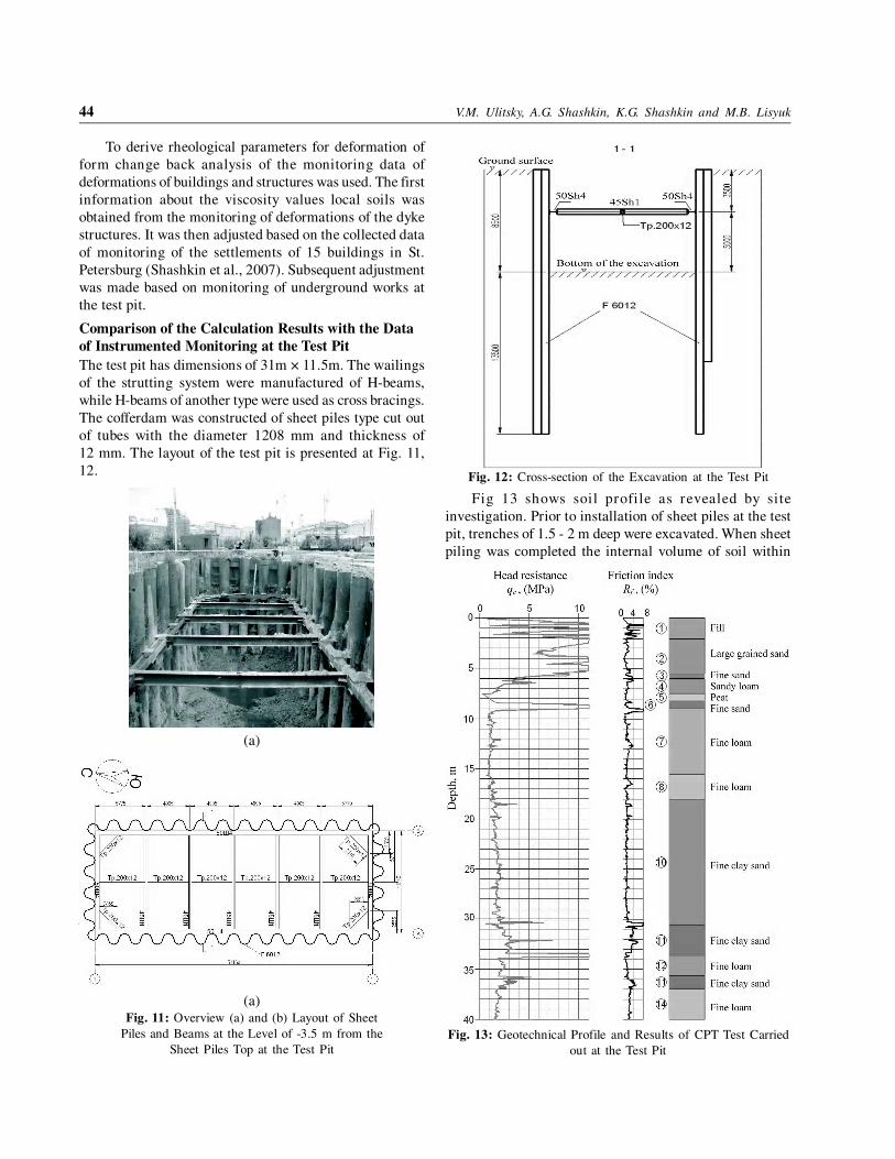
The test pit has dimensions of 31m × 11.5m. The wailings
of the strutting system were manufactured of H-beams,
while H-beams of another type were used as cross bracings.
The cofferdam was constructed of sheet piles type cut out
of tubes with the diameter 1208 mm and thickness of
12 mm. The layout of the test pit is presented at Fig. 11,
12.
(a)
(b)
(a)Fig. 11: Overview (a) and (b) Layout of Sheet
Piles and Beams at the Level of -3.5 m from the
Sheet Piles Top at the Test Pit
Fig. 12: Cross-section of the Excavation at the Test Pit
Fig 13 shows soil profile as revealed by site
investigation. Prior to installation of sheet piles at the test
pit, trenches of 1.5 - 2 m deep were excavated. When sheet
piling was completed the internal volume of soil within
Fig. 13: Geotechnical Profile and Results of CPT Test Carried
out at the Test Pit
Some Aspects of Soil-Structure Interaction in Geotechnical Engineering 45
the cofferdam was excavated down to -4m from the ground
surface following which the struts were installed and the
test pit gaps were backfilled. Thus, accompanying
monitoring at the test pit started at the second stage of
excavation, at the reference level of –4 m and down to the
level of the bottom of excavation at –8.5 m (See Fig. 14).
Analysis of the monitoring readings evidences that the
sheet pile wall generated displacement up to 5 cm, and the
settlement of non-loaded soil surface at the distance of
15-20 m totalled 18-30 mm as of the moment when the
monitoring was completed. In this manner it was proved
that the technical solution of the cofferdam and struts system
that was used at the test pit does not limit additional
settlement of the adjacent buildings to the permissible
values (2 cm for buildings of the third category of technical
condition in St. Petersburg).
Fig. 14: Position of Monitoring Equipment Near the Test Pit
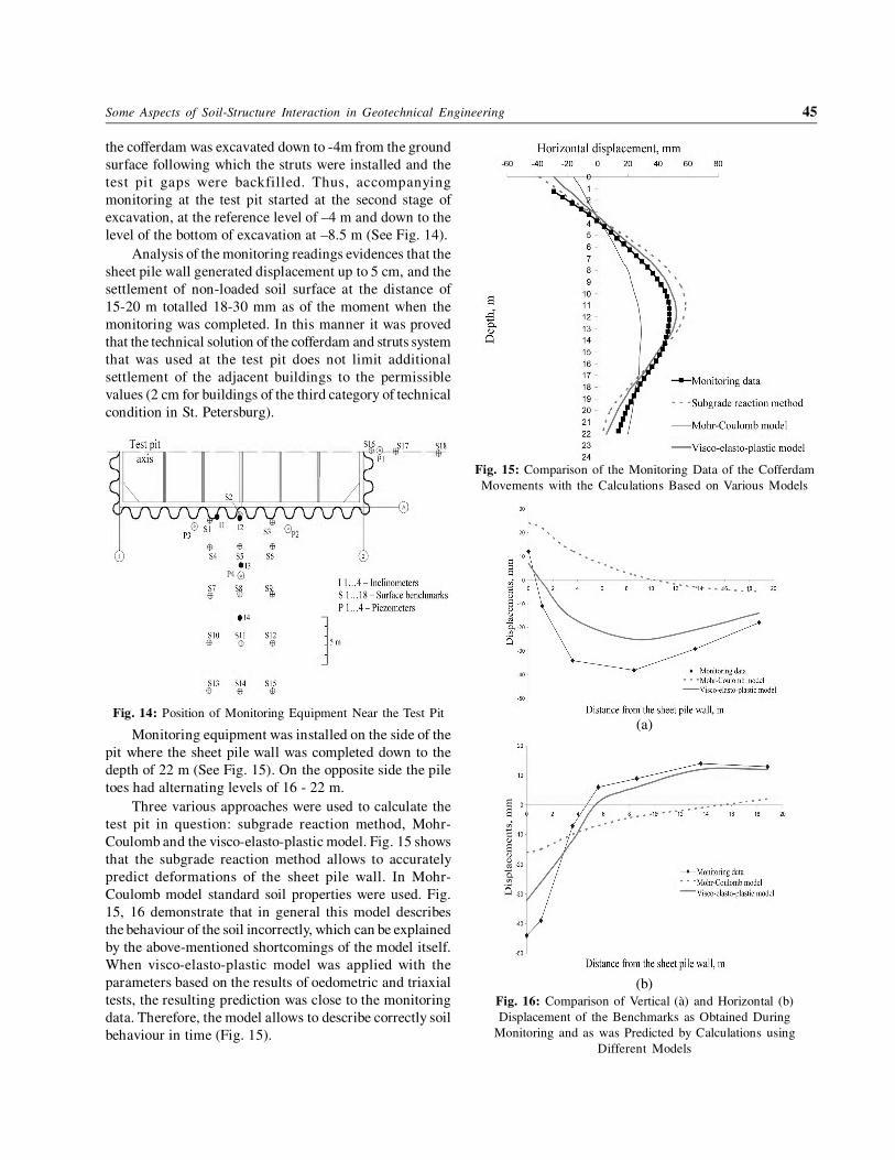
Monitoring equipment was installed on the side of the
pit where the sheet pile wall was completed down to the
depth of 22 m (See Fig. 15). On the opposite side the pile
toes had alternating levels of 16 - 22 m.
Three various approaches were used to calculate the
test pit in question: subgrade reaction method, Mohr-
Coulomb and the visco-elasto-plastic model. Fig. 15 shows
that the subgrade reaction method allows to accurately
predict deformations of the sheet pile wall. In Mohr-
Coulomb model standard soil properties were used. Fig.
15, 16 demonstrate that in general this model describes
the behaviour of the soil incorrectly, which can be explained
by the above-mentioned shortcomings of the model itself.
When visco-elasto-plastic model was applied with the
parameters based on the results of oedometric and triaxial
tests, the resulting prediction was close to the monitoring
data. Therefore, the model allows to describe correctly soil
behaviour in time (Fig. 15).
Fig. 15: Comparison of the Monitoring Data of the Cofferdam
Movements with the Calculations Based on Various Models
(a)
(b)
Fig. 16: Comparison of Vertical (à) and Horizontal (b)
Displacement of the Benchmarks as Obtained During
Monitoring and as was Predicted by Calculations using
Different Models
46 V.M. Ulitsky, A.G. Shashkin, K.G. Shashkin and M.B. Lisyuk
Fig. 17: Comparison of the Deformations Development in
Various Locations of the Soil with the Calculations Made with
the Visco-elasto-plastic Model
6. CONCLUSIONS
Soil-Structure Interaction approach is a very powerful tool
in analyses of both new and historical buildings. It allows
to depict behaviour of buildings with a good accuracy.
The example of an important historical monument
analysis deals with St. Nicholas Naval Cathedral in the
town of Kronshtadt near Saint Petersburg. This example
shows that it is very important to use soil-structure
interaction approach in design monuments preservation in
urban areas. SSI approach is very efficient at all stages of
analysis of monuments. Successful application of SSI
approach requires a very comprehensive survey of the
monuments. Essential parts of this survey are: survey of
structural elements and foundations, geophysical research,
soil sampling and testing, in-situ testing of soils. Results
of these investigations must be used in SSI analysis.
Another example deals with developing calculation
methodologies for deep pits cofferdams. In this case two
different approaches are possible. These approaches are
radically different: (1) development of simple empirical
methods, which would allow one to approach most closely
the results of in-situ measurements and (2) development of
computation methods based on analyses of physical
regularities observed in silty clay soils’ behaviour.
The advantage of the first approach is simplicity of
calculation method. However, in that case possibilities of
accurate soil deformation predictions are limited.
The advantage of the second approach is considerable
universality of the computation methodology.
The simplest elasto-plastic model with a limited Mohr-
Coulomb surface does not provide an adequate definition
of subsoil behaviour. To achieve a correct representation of
soil behaviour it is necessary to use models depicting a
difference in soil behaviour during loading and unloading,
as well as non-linear character of soil response under form
change deformations in triaxial tests. Additionally, for
computation of underground structures it is highly
important to work with realistic values of subsoil
deformation rate. As demonstrated by comparison of
calculations and the in-situ measurements the visco-elasto-
plastic model of soil behaviour produces a good accuracy
of prediction, including time-dependant deformations. This
allows to recommend the presented approach for calculating
retaining structures in soft soils and congested urban
conditions with account of soil-structure interaction effects.
REFERENCES
Bauduin, C., Bakker, K.J., and Frank, R. (2005). Use of
finite element methods in geotechical ultimate limit state
design. Proceedings of the 16th International Conference
on Soils Mechanics and Geotechnical Engineering,
Osaka, 12-16 September 2005, pp. 2775-2779.
Brandl, H. and Paulmichl, I. (2006). Substructure and
superstructure interaction of high-speed railways.
Proceedings of the XIII Danube-European Conference
on Geotechnical Engineering. Ljubljana. Vol. 2. Also
published in: Development of Urban areas and
geotechnical engineering. Vol. 11, Saint Petersburg,
2007, pp. 157-164.
Fadeev, A. and Lukin, V. (2006). Comparison of EC 7 and
SNIP approaches in design of subsoils of shallow
foundations. Osnovaniya, fundamenty i mekhanika
gruntov, No 4.
Frank, R. (2006). Design of pile foundations following
Eurocode 7. Proceedings of the XIII Danube-European
Conference on Geotechnical Engineering. Ljubljana.
Vol. 2, pp 577-586. Also published in: Development of
Urban areas and geotechnical engineering. Vol. 11,
Saint Petersburg, 2007, pp. 119-130.
Katzenbach, R., Leppla, S., Vogler, M, Dunaevsky, R, and
Kuttig, H. (2010). State of practice for the cost optimized
foundation of high-rise buildings. Proceedings of the
International geotechnical conference “Geotechnical
Challenges in Megacities”. Moscow, 7-10 June. Vol.
1, pp. 120-129.
Lee, Y.J., Bae, G.J., Hong, S.W., Bassett, R.H. (2005). Pile-
soil-tunnel interaction problem in congested urban
areas. Proceedings of the geotechnical conference ‘Soil-
Structure interaction: calculation methods and
engineering practice’. St. Petersburg, 26-28 May 2005,
pp. 195-204.
Some Aspects of Soil-Structure Interaction in Geotechnical Engineering 47
Maslov, N.N. 1977. Soil mechanics in practice of
construction. Moscow. Stroyizdat (in Russian).
Shashkin, K. (2006). Basic regularities of soil-structure
interaction. Proceedings of the XIII Danube European
Conference on Geotechnical Engineering. Ljubljana.
Vol. 1, pp 179-190.
Shashkin, A.G., Shashkin, K.G., Ulitsky, V.M., & Lutchkin,
M.A.. 2007. Design of buildings on soft clays with
account of shear strains development in time.
Development of Urban Areas and Geotechnical
Engineering. Vol.11, pp. 11-55 (in Russian)
Schweiger, H.F. 2002. Benchmarking in geotechnics.
Computional getechnics group.
TSN 50-302-2004. Design of foundations for buildings and
structures in St. Petersburg. Local construction codes
for St. Petersburg. Government of Saint Petersburg
(2004).
Ulitsky, V. 2003. Geotechnical challenges in reconstruction
of histor ical cities (as may be illustrated by
St. Petersburg). Proceedings of the geotechnical
conference “Reconstruction of historical cities and
geotechnical engineering”. St. Petersburg, 16-18
September 2003. Vol. 1, pp. 13-28.
Ulitsky, V., Shashkin, A., and Lisyuk, M. (2006).
Geotechnical problems of reconstruction of historical
cities. Proceedings of the XIII Danube-European
Conference on Geotechnical Engineering. Ljubljana.
Vol. 1.
Ulitsky, V., Shashkin, K., Shashkin A., Lisyuk, M. (2006a).
Use of soil-structure interaction approach in design
practice. Proceedings of 6th Asian Young Geotechnical
Conference, 20-21 December 2008, IIS Bangalore, pp.
27-37.
Vyalov, S.S. Reological aspects of soil mechanics. 1978.
Moscow. “Vysshaya Shkola” (in Russian).
Zdravkovic, L., Potts, D.M., St John, H.D. (2005).
Modelling of a 3D excavation in finite element analysis.
Geotechnique, Vol. LV, No 7, pp. 497-514.