some facts about long-term reliability of vibrating wire...
TRANSCRIPT

20 Transportation Research Record 1004
Some Facts About Long-Term Reliability of Vibrating Wire Instruments J. L. BORDES and P. J. DEBREUILLE
ABSTRACT
In this review of a manufactur e r 's experience during the last 50 years, the durability and stability of vibrating wire (acoustic) monitoring instruments are discussed and statistics on survival rates are presented. The causes of instrument failure are analyzed; the factors that affect and the mecnanisms of zero drift are discussed. The relationship between instrument failure and cable laying, manufacturing process, and cable connections is discussed. Analysis shows differenc;:es in zero drift between plain strain gauges and complex sensors. Mention is made of the influence of wire behavior and sensor structure. There is discussion of factors that affect wire and sensor structure aging. Special tests on aging are described. Various tests on long-term observation of a wire or a sensor are summarized. Examples are given of instruments still faithfully operating several dozen years after installation. Those examples involve dams in operation. Although reliability factors considered are limited to survival and time stability, some consideration is given to quality of sensor response and to other aspects, such as resonance, that affect reliability. on the basis of an analysis of data from two types of sensors, it is concluded that vibrating wire instruments offer an extremely high degree of stability, accuracy, and durability.
The views of a manufacturer, whose only merit has been that of being a pioneer in the application of the vibrating wire instrument to civil engineering projects, are presented. The time span covered is thought to justify this review, which presents facts that may help the reader make up his own mind about the long-term reliability of vibrating wire instruments.
This is not an exhaustive review, but simply a set of facts and figures that cover a long period of time in this relatively new industry. The review begins with a short historical summary of the manufacturer's practical background including a definition of what is meant by long-term reliability, which serves as a basis for comparing the examples cited.
It was between 1928 and 1931 that Andre Coyne in France, independent of other attempts in Germany, conceived a method of measuring the strains in solids by measuring the change in the frequency of a vibrating piano wire stretched on a frame attached to, and deforming with, the monitored structure. This arrangement, among other advantages, lent itself to remote reading of the output signal. By 1932 the first 36 vibrating wire strain gauges had been installed in Bromme Dam in France; this dam was retired from service about 1950. Then Mareges Dam, the world's highest and first double curvature arch dam, was equipped in 1934 with 78 vibrating wire strain gauges, from which readings were taken until 1953 (_!).
Between 1934 and 1938 instruments were built into a bridge, the hoop reinforcement around penstocks, and ground anchors for a wharf wall; the same vibrating wire principle was used to manufacture pressure cells for direct burial in soils and for making dynamic recordings of water hammer (1). Despite the Second World War, many other structures were instrumented from 1938 to 1947: tunnels, underground chambers, gates, and valves as well as dams.
In 1947 A. Coyne and J. Bellier, who together had been responsible for this development, founded a company, Telemac, to promote vibrating wire instruments for civil engineering applications. The next major step forward, in 1954, was a twin-coil instrument in which one coil imparted just enough energy to the vibrating wire to prevent decay while the other could be used for continuously recording the output signal.
Telemac defines long-term reliability as comprising (a) the physical durability of the instrument, which enables it to perform reliably for dozens of years after installation and (b) time stability (i.e., there should be no zero drift and any reading at any time can be referred to the same datum) • The second point also includes the concept of minimum change in sensitivity or "dead band" with time <l>.
A few examples will be given to illustrate how vibrating wire instruments are intrinsically capable of offering the durability and reliability necessary for civil engineering uses. When reading the statistics, it should be borne in mind that an instrument may in practice become unserviceable, from the operator's point of view, because of minor extraneous faults that can be quickly put right so that some wastage (nonfunctioning instrument) is recoverable.
DURABILITY
The number of instruments manufactured by Telemac since it was founded in 1947 will serve as a measure of the experience acquired by the company. To date, Telemac has built 45,000 vibrating wire strain gauges plus approximately 8 ,000 vibrating wire pore pressure and total pressure cells, aside from other types of instruments such as inclinometers, the performance analysis Of wnich is extremely complex and the number of which is limited. The overall statis-

Bordes and Debreuille
tical picture will be examined before a few specific cases are described.
General Statistics
The most accurate record s ha ve been kept by Electric i te d e F rance (3), cover ing 3,300 stra i n gauges, 1,400 p iezometer cells i n d a ms , and 2, 0 00 strain gauges in nuclear power stations. These instruments represent 13 percent of total Telemac production.
The oldest instruments (dam strain gauges) had been in continuous use for 30 years in 1975 when the records were compiled and have now been in service for 40 years. Of a total of 3,346 strain gauges, 5 percent became unserviceable in the first year, but only 18 percent were unserviceable after 30 years, an annual ra t e of l oss of 4 .1 x lo-' not counting the first-ye ar failures . Statistics on 3,300 strain gauges during the 8-year period 1974-1982 give an annual loss of O. 7 x 10- ', making a 50-year total of less than 4 percent. Figure l(a) shows number of instruments plot ted against time instal l ed . Figure l(b) shows annual losses plotted against time .
3000
2000 ":.
~ .....
100 i.., :i; ~ "<{
~ 0 "' o~
BO ~
l<. Cl
'-60
..... i:::
\ ~ i5
40
20
·~ 0
0
10
• ~ • • •• . -
10
(a)
STRAINMETER INSTALLED HAVING PERFORMED SATISFACTORILY
OR NOT •a• YEARS
20 YEARS 30
(b)
STRAINMETERS UNSERVICEABLE. DURING YEAR "0+1°FOR
100 0 INSTRUMENTS
-· ···-20 YEARS 30
FIGURE 1 Vibrating wire strain gauges in service (from documents of Division Technique Gimerale d'Electricite de France).
Specific Statistics
Table 1 gives details about 10 of approxima tely 250 dams fitted with Telemac instruments, ranging from the old Mareges Dam to Grand'Maison, now under construction in France. Other examples are drawn from the American continents, Asia, and Africa. Examples are confined to dams because they represent the oldest single consistent type of engineering structure; nuclear reactor buildings are a relatively recent addition and underground chambers have only been instrumented infrequently in the past. Examining both old and new dams reveals certain definite
21
trends, particularly in connection with the installation of instruments. The dams are chosen from all parts of the world where skills and material resources are different, and these are two factors that may have a significant impact on the success or failure of the instrumentation system. The actual choice of dams is quite arbitrary; others could have served just as well.
An attempt has been made to break down the numbers in the same way Electricite de France did, to distinguish between instrument failures in the first year of installation and those that occur after the dam has been commissioned. Statistics for recent years reveal that only a small percentage ( 1 to 2 percent) of the total number of instruments may be lost, but this involves questions of workmanship and super v i sion on site, which are beyond the scope of this paper.
The gross wastage is reasonable (not more than 25 percent not counting the 18 instruments lost at Kariba from extraneous causes). It is important that the unserviceable instruments not be concentrated in critical zones of the structure to such an extent that no information is available, and the numbers must also be corrected to account for the utility of the remainder (e.g., the loss of one strain gauge in a three-axis rosette renders the other two useless). such considerations are important in instrumentation system design, where a certain degree of redundancy must be built in, and this too is beyond the scope of the present paper.
Nevertheless, the numbers given in Table 1 show that vibrating wire instruments offer excellent durability, which can be further improved by regular maintenance. Maintenance work at dams like Kariba in Zimbabwe has shown that instruments considered unserviceable can be recovered, so the statistics are somewhat overconservative for some of the dams listed. It can be reasonably estimated that, with modern methods and reasonably good site conditions, 80 percent of the instruments can be expected to be operating satisfactorily after 50 years if the notion of utility, mentioned previously, is disregarded. A loss of 20 percent of instruments may be critical in some circumstances.
It is important to note as well that vibrating wire instruments have been used satisfactorily in dynamically loaded structures such as driven piles, railway bridges and tunnel linings, suspension bridges, and offshore platforms. In the last case, continuous measurements were made over periods of several months.
Wastage Fa c t o rs
By far the most important factor in instrument failure is damage to the cable during installation. Rough handling or difficulties caused by site congestion may cut or puncture the outer casing, enabling water to seep in. Water will impair operation even if it does not reach as far as the instrument itself. Sensors may suffer damage several years after installation in some situations. Such damage to buried cable is irreparable.
Another cause of failure is careless workmanship in manufacturing; failure may occur if metal particles from the machining processes are allowed to fall into the gap between the coil and the wire (such particles sometimes dislodge spontaneously). There have been rare cases of the piano wire corroding quite quickly; this is attributable to the ins trument not being watertight.
The last major factor in instrument wastage includes all the defects that can occur in the cable and connections from the junction boxes to the read-

22
TABLE l Dams Fitted with Telemac Instn.1ments
No. of
Transportation Research Record 1004
Failures Immediately After Installation
Subsequent Failures
Total Failures
Vibrating Wire Country Dam When Built Instruments No. Percentage No. Percentage No. Percentage
France Mareges 1932-1935 76'·b Castillon 1946-1949 104'
Tunisia Oue<l Mellegue 1952-1954 958
Zimbabwe Kariba, main dam abutment 1955-1959 261 3
62' Canada Daniel Johnson (formerly Manicouagan V) 1959-1968 57•
l,066' Pakistan Tarbela 1968-1976 110° Algeria Sidi Mohamed Ben Aouda 1974-1977 114° Venezuela Guri 1979-1982 335° Argentina Alicura 1981-1984 132° France Grand'Maison 1979-1985 120•
13 4
2 18
3 4
s 6
2 16
2 3
24 30
20 6
9 49
18 5
17 16 24 25< 37 14 34 55d 0 0
53 5 22 20 24 l 8f
7 2 3 2 4 38
~Strain gau111.1~. . . . . . . · An attelllpl IS to be made to take readmgs from the Junction boxes themseJves on instruments read until 1953 (when cable was cut below junctmn boxes on downstream face to further maml et\(WCC work).
~Junct lOn box~ atl3 :cwpech!:d pnrlln l c:awc or mis(uucllonln~ ornurny of the unreadabte sensors. Eis:h<ee.n u11p1· ... ic1rnblet duo to (l9TfO:S IDll or torm h1At1.
~Cl. I poi< pre,.urc ce lls. NIHc un~rvitanblt tat iMtn llallon (6%) 1 !J ou l of we- due io CQb lt cm in a slide.
1Th rt c- UnJCrvlcc.Qblc duC" to ccablc cul ar1er J lf(cri:otla l .a eulemen t.
out equipment. Such damage may be reparable and the decision to refurbish junction or switching boxes, or both, and change lengths of multicore cable can sometimes enable significant numbers of instruments to be reinstated. But if the terminals between the boxes and the individual cable from the instruments start to leak, there is no way of recovering that instrument. The vulnerable points in the system should therefore be regularly inspected and any maintenance work needed should be undertaken promptly.
Another cause of instrument failure is lightning, which can destroy both coils rendering the instrument totally irrecoverable. Protection is a simple matter of burying the cables more than 1 m deep. If this is impossible, each cable must be run through an earthed metal pipe conduit. All circuits should be short-circuited whenever there is any risk of direct strikes. Special devices like spark gaps and diode bridges can be incorporated in the switching systems, but there is no guarantee of their effectiveness.
The presence of two coils in modern vibrating wire instruments means that, if one is destroyed by li.ghtning or is defective when it leaves the factory, the sound one can still be used to "pluck" the wire and set it vibrating as well as to pick up the wire's frequency, although in this case the vibrations will decay and the reading procedure is slightly d ifferent . Statistics s how that some percentage of i nstruments can be recovered in t h is way.
At one recent job in an area of high lighting frequency, an installation er r or enabled lightning to damage nine instruments out of a total of 14 i eight of these instruments had only one coil damaged and could still be used for meaningful readings.
Exceptional Damage
In some rare cases, there has been an unusually high mortality rate in the population of strain gauges installed in a structure--as high as 25 to 30 percent over a period of 10 years or even as high as 50 percent over an even shorter period. Such failures have always been found to be due to special circumstances.
The worst case was due to poor workmanship and severe damage caused in lay if19 th~ cable. A more un usual case involved strain gauges encased in brass and built into a nuclear reactor building. Tests
have shown recently that radiation affected the seals and the piano wire itself so that the instruments could not function.
A third case still remains obscure, might be that some unnoticed defect in ture of a batch of instruments led to failure of all of them.
although it the manufacthe eventual
This is a good opportunity to stress that manufacturers should not be overly hasty in introducing new manufacturing processes or new materials. Once installed in a large structure, the instruments are inaccessible and repairs impossible, and there is the added problem of determining what actually went wrong. The difficulty of predicting the long-term effects of design or manufacturing modifications means that manufacturers must think hard before trying to improve their techniques, although strict quality control does help in improving the technology.
TIME STABILITY
Unlike durability, which is relatively easy to quantify, time stabil ity or lack of zero drift is difficult to evalua te object i vely . Zero drift is not an all-or-nothing effect, so it is necessary to assess the accuracy of the instrument's response and include the time factor in judging instrument performance. This is a complex task that involves the sorting of a large amount of data. Unfortunately data reaches the manufacturer only in a haphazard fashion, and purchasers and users can only refer to their own limited experience, so it is extremely difficult to attempt any synthesis of information from several clients and engineering consultants.
Despite the sparseness of data, it is still possible to cite a few examples to analyze the intrinsic quality of vibrating wire instruments and the factors that affect zero drift.
zero Dr i ft Factors and Mechanisms
There are two groups of factors that affect timestability perf ormance and that depend on the crucial distinction between a plain strain gauge cast into the structural concrete and an instrument in which ths piano ~·:i!"e actual!~, meas•1res t he a~formations of a membrane or o ther deformable part, as does the pore pressure cell. The second category of instru-
Bordes and Debreuille
ment also includes plain strain gauges attached to the surface of the structure.
In the case of plain strain gauges, the only factors involved are changes in the piano wire itself and in its end attachments, whereas in the second category, the situation is further complicated by the sometimes complex changes in the membrane or in the method of affixing the strain gauge to the structural surface.
The grade and treatment of the piano wire and the low loads to which it is subjected (9 to 13 percent yield strength) make it inconceivable that there can be any irrecoverable time-dependent strain of any significant magnitude (4). However, there is always the possibility that th~ end fixings act as stress raisers, eventually causing irrecoverable strain in the wire.
When the stout tube protecting the piano wire was filled with atmospheric oxygen, there might have been a possibility of microcorrosion gradually reducing the diameter of the wire, especially if it had been damaged by an excessive clamping force at the end attachment points. Proof of this argument may be that a reduction in wire diameter causes the resonant frequency of the wire to increase. Several recorded cases of zero drift show an increasing frequency.
Zero drift is difficult to detect because it may be only two or three cycles per second per year or O.s-• percent of the instrument range per year, small enough to be concealed by the deformations of the instrumented structure. Manufacturers have attempted to overcome the problem to some extent by designing attachment points that do not damage the wire and by filling the instrument casing with a neutral gas like nitrogen or evacuating the casing.
Zero drift caused by the slow deformation of the membrane or other deformable part is more difficult to understand. It is affected by shape and material, and assembly and treatment methods.
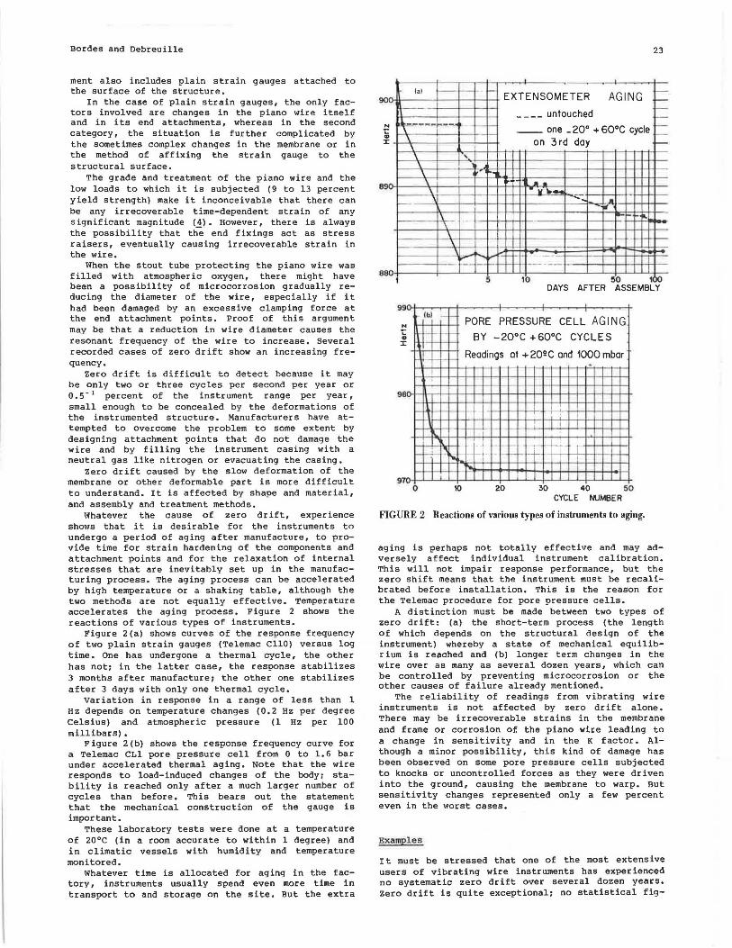
Whatever the cause of zero drift, experience shows that it is desirable for the instruments to undergo a period of aging after manufacture, to provide time for strain hardening of the components and attachment points and for the relaxation of internal stresses that are inevitably set up in the manufacturing process. The aging process can be accelerated by high temperature or a shaking table, although the two methods are not equally effective. Temperature accelerates the aging process. Figure 2 shows the reactions of various types of instruments.
Figure 2(a) shows curves of the response frequency of two plain strain gauges (Telemac CllO) versus log time. One has undergone a thermal cycle, the other has not: in the latter case, the response stabilizes 3 months after manufacture: the other one stabilizes after 3 days with only one thermal cycle.
variation in response in a range of less than 1 Hz depends on temperature changes (0.2 Hz per degree Celsius) and atmospheric pressure (1 Hz per 100 millibars) •
Figure 2(b) shows the response frequency curve for a Telemac CLl pore pressure cell from 0 to 1. 6 bar under accelerated thermal aging. Note that the wire responds to load-induced changes of the bodn stability is reached only after a much larger number of cycles than before. This bears out the statement that the mechanical construction of the gauge is important.
These laboratory tests were done at a temperature of 20°C (in a room accurate to within 1 degree) and in climatic vessels with humidity and temperature monitored.
Whatever time is allocated for aging in the factory, instruments usually spend even more time in transport to and storage on the site. But the extra
90 -' Y
N t: ., :I:
-y 89
ae 0
23
---.---,-(al '- -EXTENSOMETER AGING -._ I-
____ untouched <--, _,,._,....,....,....
h.- - -· ~ __ one _ 20° + 60°C cycle · --\ on 3rd day \ -\ ' \
\ ·r-: k,. r~ \ ~ .. - --\ -... -
'--- ' -~ . " \
\ \ \
_,_ -' ~
-- --I- I- 1-1- ~ --·--- I
1 5 10 50 1Xl DAYS AFTER ASSEMBLY
99
N
... ., :I:
-
-98 ·-
lb) - '-
\1-_.__,__
- - L-1-
\
'
'
PORE PRESSURE CELL AGING
BY -20°c +60°C CYCLES
Readings at + 2Q!!C and 1000 mbar ~-~
.
-t I
1-'-y_ ._ I t
_ .....:_
970 0
' I I
- .I
- ~ - -~t-~
10
- ·-~ I
-~ ~ - -
20 30 40 50 CYCLE M.IMBER
FIGURE 2 Reactions of various types of instruments to aging.
aging is perhaps not totally effective and may adversely affect individual instrument calibration. This will not impair response performance, but the zero shift means that the instrument must be recalibrated before installation. This is the reason for the Telemac procedure for pore pressure cells.
A distinction must be made between two types of zero drift: (a) the short-term process (the length of which depends on the structural design of the instrument) whereby a state of mechanical equilibrium is reached and (b) longer term changes in the wire over as many as several dozen years, which can be controlled by preventing microcorrosion or the other causes of failure already mentioned.
The reliability of readings from vibrating wire instruments is not affected by zero drift alone. There may be irrecoverable strains in the membrane and frame or corrosion of the piano wire leading to a change in sensitivity and in the K factor. Although a minor possibility, this kind of damage has been observed on some pore pressure cells subjected to knocks or uncontrolled forces as they were driven into the ground, causing the membrane to warp. But sensitivity changes represented only a few percent even in the worst cases.
Examples
It must be stressed that one of the most extensive users of vibrating wire instruments has experienced no systematic zero drift over several dozen years. zero drift is quite exceptional: no statistical fig-

24
ures can be given. In Guri, out of 335 pore pressure cells, two zero drift tendency cases were detected. Such an example is cited to illustrate the general behavior of the sensors. The following examples have no statistical significance; they are merely illustrative. The foregoing section is intended to demonstrate how limited the issue is and how it can be overcome,
That a vibrating wire strain gauqe can operate at all after 40 years of service is outstanding, but it is more important that its reliability is coupled with high sensitivity, making it an invaluable and highly effective tool in analyzing structural behavior in civil engineering. Therefore a few case histories of medium- and long-term performance of vibrating wire instruments will be described.
Example 1
Readings were taken over a period of 24 months in 1952 and 1953 from a pore pressure cell on which a constant weight applied a force of approximately 2 kg/cm 2 (5) with corrections for temperature and barometric pressure. The response of the cell remained constant to within ±3 x 10" 1 of the range.
Example 2
Three pairs of strain gauges, 160 mm, 200 mm, and 260 mm in length, cast in concrete cubes measuring 500 mm on a side were read regularly from 1965 to 1960 (Archives Telemac). The cubes were kept outdoors with no protection from the weather. Concrete surface and internal temperatures were recorded to correct the strain gauge readings. During this 4-year period, there was a shortening of from 120 x 10- 6 to 160 x 10" 6 , strain shrinkage included, representing 4 to 5 percent of the instrument range. There is a definite scale effect: the recorded shrinkage reading increased with instrument length. It is also true that shrinkage is usually more than 100 x 10" 6 strain over 4 years. The shrinkage rate dropped to 20 x 10 - 6 per year in the fourth year. These simple tests demonstrate the robustness of the instruments and give an approximate idea of their time stability.
Transportation Research Record 1004
Example 3
An unloaded load cell was recorded from 1974 to 1970, so that it responded only to temperature changes (Archives Telemac) • The output frequency at 20°C varied by only one cycle per second over 5 years (the actual readings were 024 to 025 Hz), representing a frequency error of 10-' and a strain error of 3 x lo-• (Figure 3).
Example 4
Extensometers were compared in connection with the construction of the Washington Subway Project (6), including Telemac SC-type surface-mounted strain gauges. Laboratory drift in SC 11 instruments was as much as 40 x 10- 6 strain in 50 days with a clear tendency to stabilize after 35 days. No significant zero drift was detected with the SC B instrument. Temperature tests between 0°C and 55°C revealed a clear temperature effect: at 55°C, drift in the SC 11 was BO x 10" 6 with no tendency to stabilize after approximately 15 days, but this effect was only approximately 15 x 10- 6 for the SC B, stabilizing after 15 days.
Example 5
Records were kept over a period of 5 years (1975 to 1900) from 20 CHO strain gauges and 30 platinum resistance wire thermometers in the single-span isostatic Condren Bridge in France, as part of a research project of the Laboratoire Central des Ponts et Chaussees Ill· Two of the strain gauges, although buried within the concrete, were not subject to structural loads and measured only the concrete shrinkage.
Analysis of the readings, corrected for temperature changes and shrinkage, revealed no detectable zero drift. Strains over the whole period were estimated to within 5 x 10" 6 or 3 x 10-' of the range, similar to the values already mentioned in the first and third examples.
FREQUENCY
FIGURE 3 Long-term observation of a load cell.
Bordes and Debreuille
Example 6
During tests conducted in 1981 and 1982 in a pilot underground liquefied natural gas cavity (8), surface-mounted strain gauges were subjected to a temperature of -196°C for several months with no deleterious effects. Earlier tests had shown that their response between 0°C and -196°C was not affected or, at the most, was affected by only lo-• of the range.
Example 7
The examples may be considered rather limited and the reader may wonder why they were not pursued longer. It must be remembered that any laboratory or other setup will be more subject to error, the longer it is maintained. Long-term tests necessarily involve different observers and the results, whether
1" FILLING OF RESERVOIR
25
good or bad, are therefore always open to controversy.
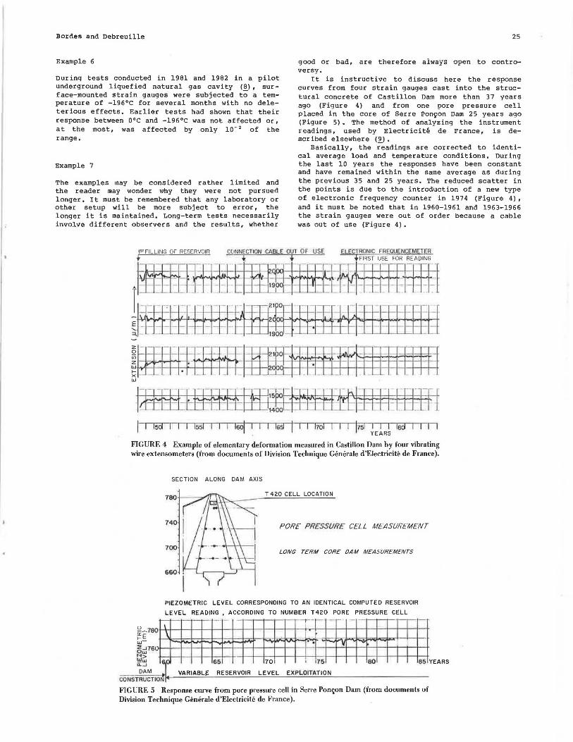
It is instructive to discuss here the response curves from four strain gauges cast into the structural concrete of Castillon Dam more than 37 years ago (Figure 4) and from one pore pressure cell placed in the core of Serre Ponyon Dam 25 years ago (Figure 5). The method of analyzing the instrument readings, used by Electricite de France, is described elsewhere (9).
Basically, the readings are corrected to identical average load and temperature conditions. During the last 10 years the responses have been constant and have remained within the same average as during the previous 35 and 25 years. The reduced scatter in the points is due to the introduction of a new type of electronic frequency counter in 1974 (Figure 4), and it must be noted that in 1960-1961 and 1963-1966 the strain gauges were out of order because a cable was out of use (Figure 4).
ELECTRONIC FREOUENCEMETER FIRST USE FOR READING
l-+-~ill)Q-l-l-++~1~f-b-hl·~--l-l--l-l·-l-l-l--!-l-4
~ - - - - - - -· - -·l--l- l-l---cl--1- 1-i
::i. -
~~- ·---- -·-- ---- -- - -
1- -- -~- 21bo - ·- ·---.~rll':J::::l=+:=l~=f;H;:;;::-
~ - ; -·~~w"""l"i!-wol.- 1- ~ - ::-::11:__:.l....21~~~~::j:!~:it~ ,__ _ ,___ _ '-_ ,___ - 1--1--1-+-I
~ • cpo--t--t-+-+-+-+--+--+--+-+--t--+--t--t--t---t--+-+--t x -·-w
l15i I I I lad I I YEARS
I I 15d I I ls5I I I I lsoi '. I I ls51 I !1oi
FIGURE 4 Example of elementary deformation measured in Castillon Dam by four vibrating wire extensometers (from documents of Division Technique Generale d'Electricite de France).
SECTION ALONG DAM AXIS
PORE PRESSURE CELL MEASURt.MENT
LON(; TERM CORE OAM MEASt/REMENTS
660
PIEZOMETRIC LEVEL CORRESPONDING TO AN IDENTICAL COMPUTED RESERVOIR
LEVEL READING , ACCORDING TO NUMBER T420 PORE PRESSURE CELL
DAM VARIABLf: RESERVOIR LEVEL EXPLOITATION CONSTRUCTIONn....--'--'-"-'--""-~-"-'--~~--'=-...;;..;~""--"'-'---~-'-"'--~~~~~~~~~~-
Fl GU RE 5 Response curve from pore pressure cell in Serre Pom;on Dam (from documents of Division Technique Generale d'Electricite de France).

26
It is unfortunately impossible to analyze all the other instruments in place throughout the world. But the curves shown in this figure are not exceptional. They are typical of vibrating wire instruments in general.
OTHER ASPECTS OF RELIABILITY
At th~ beginning of this paper, it was olearly stated that a comprehensive review of all vibrating wire reliability factors was not intended. Reliability is taken in its most restricted sense of durability and zero drift. These are indeed the most important aspects because the instruments are usually inaccessible, once installed. But, even in the gauge itself, there are other factors, and it is important to note that, if reliability is defined as the probability of a measuring system working properly, other important factors are precision, resolution, and reproducibility, which to some degree depend on zero drift and hysteresis.
A detailed discussion would be too long, but it is appropriate to briefly discuss deviations from straight-line responses of the square of the vibrating wire frequency and the porous "pressure inlets• of pore pressure cells.
A study of instrument output signals reveals that deviations from the straight-line response are caused chiefly by resonance of part of the instrument over a usually quite limited frequency band. This is more common when the measured strain is transmitted through the instrument body. Resonance leads to energy loss from the wire and alters the signal, whence the deviation. But this energy loss also weakens the signal so that it may be inaudible at a distance of only 200 or 300 m or even much less, compared with the usual transmission distance of 1000 m. This "blackout• may occur in only an extremely small bandwidth.
The manufacture of reliable instruments requires thorough knowledge of their mechanical properties. Experience shows that resonance can be eliminated by the factory quality control system so that the straight-line error is only l/lOOOth of the full range.
As mentioned previously, reliability also requires first-class peripherals, the components of which (except the buried cable) are accessible for repair, but these parts are beyond the scope of this paper.
The pressure inlet tip or porous stone of pore pressure cells is made of a fine porous material to enable the water pressure to gain access to the membrane inside the cell. For fine grained soils, the pores are very fine. The tip is now thoroughly saturated in the factory with deaerated water before delivery. Special tests show that it remains saturated and pressure equilibrium is reached when the instrument is installed, regardless of whether the surrounding soil is saturated. It is important for the porous tip to have proper hydraulic performance if the pore pressure gauge is to be reliable. The problem has now been just about solved and merits a longer discussion.
CONCLUSION
It must be pointed out again that the present analysis is limited to strain gauges and pore pressure cells. It must be remembered that only these two instrument types can be considered statistically meaningful. They have been in use in large numbers
Transportation Research Record 1004
for many years, and their response is simple enough for the findings to be universally acceptable. It is remarkable that these instruments have changed little over the years and so the findings are not invalidated by recent changes in construction.
Although all the instruments discussed in this paper come from the same manufacturer, the conclusions drawn have a much wider scope. They apply to all vibrating wire instruments, provided of course that their construction meets a high standard.
It can reasonably be concluded that, after several decades of use, the durability and stability of vibrating wire strain gauges offer outstanding qualities of reliability for the monitoring of civil engineering structures.
Only proper care and skill in installing and maintaining the instruments enables the full benefit to be drawn from them, but simple precautions will ensure faithful service for several dozen years, and 80 percent of an installation can be expected to still be operating after 50 years. Instrument reliability is remarkable: there are few documented cases of significant zero drift, and proper manufacturing, aging, and installation procedures will keep the number of instruments affected to an absolute minimum. Adequate quality control procedures at each stage of design and manufacture are needed to prevent anomalous operation.
ACKNOWLEDGMENTS
The authors would like to thank G. Douillet, Division Technique Generale, Electricite de France: M. Diruy, Laboratoire Central des Ponte et Chaussees, Paris: A. Pujol, Hydronor: L. Pi Botta and C.A. Anderson, Consulting Engineers Group for Alicura Dam, Argentina: Mr. Abid, Tunisian Ministry of Agr iculture: J.F. Capelle, Roctest: M. Popiel, HydroQuebec, Canada: K. de Fries, Consulting Engineer, Caracas: the Water and Power Development Authority, Pakistan: Coyne & Bellier, Consulting Engineers, Paris: and TAMS, New York, for their kind permission to use information in this paper.
REFERENCES
1. A. Coyne. Quelques resultats d'ausculation sonore sur les ouvrages en beton, beton arme ou metal. Annalee ITBTP, Paris, France, July-Aug. 1938.
2. Terminologie relative aux performances des instruments de mesure. Techniques de l' Ingenieur, 160, Paris, France.
3. G. Douillet. Communication au Colloque du Comite Technique du comite Fran~ais des Grands Barrages. Division Technique Generale, Electricite de France, Paris, Jan. 1978.
4. C.K. Lanner, Strain Aging in Cold-Drawn Wire. Springs, May 1983.
5. J. Bellier and L. sabbat. Preuve exper imentale de la fidelite immuable des cordes vibrantes. Report 32. Symposium sur !'observation des ouvrages, Laboratorio Nacional de Engenharia Civil, Lisbon, Portugal, Oct. 1955.
6. T.D. O'Rourke and E.J. Cording. Measurement of struts Loads by Means of Vibrating Wire Strain Gages. Proc., ASCE Specialty Conference on Performance Mani tor ing for Geotechnical Construction, 1975.
7. Etude generale des procedes de mesure utilises dans lee laboratoires: lee temoins sonores,

Transportation Research Record 1004 27
bilan de 5 annees de mesure sur le point de Condren. Laboratoire Central des Ponts et Chaussees, Paris, France, 19BO.
8, P. De Sloovere. Mesures extensometriques dans une cavite refroidie a -196°C. Symposium International Essais en Place, Paris, France, 1983,
9. F. Lugiez, N. Beaujoint, and x. Hardy. L'auscultation des barrages en exploitation au service de la production hydraulique d 'Electr ici te de France, des principes aux resultats. Question 3 8, Report 33. lOeme Cong res International des Grands Barrages, Montreal, Quebec, Canada, 1970.
Instrumentation Reliability at Harvard Square Station
ROBERT P. RA WNSLEY, HENRY A. RUSSELL, and WILLIAM H. HANSMIRE
ABSTRACT
As a result of recent emphasis on mass transit, the Massachusetts Bay Transportation Authority has undertaken a large expansion program for its rapid transit facilities. Part of the expansion program was to modify the existing Harvard Square Station in Cambridge, Massachusetts. Slurry walls (concrete cast in place within slurry-filled trenches) were emploved for both excavation and final lateral support. In some instances the wall passed within 7 ft of existing buildings of Harvard University. Concern for those buildings resulted in the use of specialized instruments to measure ground, building, and slurry wall movements. The instrumentation program had sufficient redundancy that key parameters were measured by more than one instrument. In addition, detailed field observations were recorded to accurately relate the instrument measurements to construction activity and geologic conditions. In most cases, the instruments performed as well as or better than anticipated. Some instruments were found to be inappropriate for the actual construction conditions. In the cases of poor instrument performance, sufficient redundancy existed that adequate measurements by other instruments were able to serve the monitoring function. The key to the reliability of the instrumentation program was the people involved. Instrumentation installation was done by experienced professionals. Instrument monitoring was performed by trained people who were on the job for extensive periods of time, were interested in the results, and were responsible for interpreting the measurements.
As a result of the recent emphasis on mass transit, the Massachusetts Bay Transportation Authority (MBTA) of Boston, Massachusetts, has undertaken a large expansion program for its rapid transit facilities. A major portion of this expansion program is the extension of the heavy rail Red Line northwest to the Alewife section of Cambridge, Massachusetts. To accomplish the 3-mile extension, the existing Harvard Square Station had to be modified and enlarged to allow realignment of the tracks to enable them to pass through the existing station and make a turn of approximately 90 degrees to the north. The modification of the station required nearly complete demolition of the existing structure and construct ion of new entrances and passenger platforms.
Slurry walls were employed for both excavation and final support. In some areas the slurry wall passes within 7 ft of existing buildings of Harvard University. Because of concern about ground and
building movement, extensive instrumentation was used.
In addition to monitoring movements, strain gauges and pressure cells were installed in the slurry wall at selected locations to better determine the actual slurry wall behavior. That instrumentation was added as an FHWA/UMTA research effort after construction had started, A site plan and typical section of an instrumented panel are shown in Figures 1 and 2, respectively. A summary of the field monitoring is presented by Hansmire et al. (_!).
INSTRUMENTATION PROGRAM
The primary purposes of the instrumentation and monitoring were to provide reliable information, to foresee problems, and to allow corrective measures to be taken to prevent damage to adjacent struc-