some present day trends in engineering metrology
TRANSCRIPT

SOME PRESENT DAY TRENDS IN
ENGINEERING METROLOGY
by C. O. TAYLERSON, M.B.E.,
Senior Experimental Officer,
Metrology Division, National Physical Laboratory.
Mr. C. O. Taylerson
An abridged version of the Paper presented to the Coventry Section of the Institution, 20th November, 1952
T HE march of progress in engineering metrologyhas been considerable since the turn of the
century. This has been due largely to the impetusof the two intervening World Wars. In both Warsthere was a heavy demand for interchangeable partsof a precise nature and mass production of this kindwould be quite impossible unless controlled by evenmore precise measuring techniques. Prior to 1914engineering measuring equipment available rarelywent beyond the hand micrometer or calliper gauge,whereas today there is a seemingly inexhaustiblesupply of equipment available for making almost anytype of measurement that is likely to confront themodern engineer. Such is the progress that has beenmade.
Fig. 1 C.S.I. Bench Microscope for measuring small screws
Optics as an Aid to MeasurementOptical methods of amplification are extensively
employed in modern measuring instruments; indeed,this technique is applied nowadays to some machinetools. This is no new departure, as some of theearliest measuring instruments produced, of whichthe bench microscope (Fig. 1) is an example, madeuse of optics. Then during the First World War theoptical projector (Fig. 2), a British invention, wasintroduced and developed. There are produced to-day in many countries countless types of opticalprojectors for use in engineering metrology. Fig. 3shows the N.P.L. heavy type projector.
It was during the 1930's that Carl Zeiss of Ger-many introduced optical methods of amplification toa number of measuring tools and instruments. Zeissfirst fitted the reading microscope to these. Thismeant pioneer work as there was a natural aversion,particularly in the workshop, to the use of themicroscope. A typical example was the toolmaker'smicroscope (Fig. 4). This instrument was an answerto certain limitations..of the optical projector. It wasnot possible on this latter instrument to project, atone setting, an object much greater than about oneinch in size. The toolmaker's microscope overcamethis limitation. By mounting a microscope, to beused fiducially, over a co-ordinate slide controlled bymicrometers set at 90° to each other, objects in oneplane up to 4 inches by 2 inches in size could bemeasured. Other measuring tools to which opticalprinciples were applied followed in quick succession;these included the optical dividing head, the opticalrotatable table and the optical protractor.
The immediate effect of the introduction of opticsto these tools and instruments was to increase theirefficiency .and also to enhance their accuracy of
233
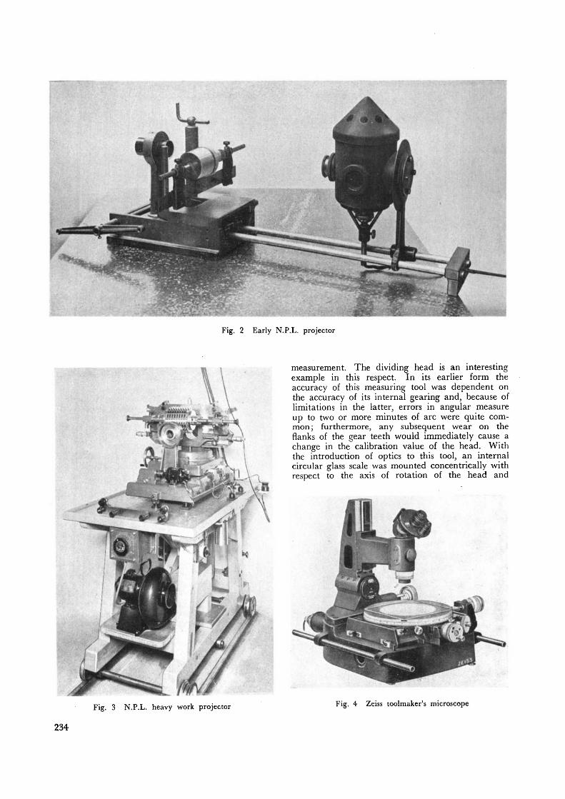
Fig. 2 Early N.P.L. projector
measurement. The dividing head is an interestingexample in this respect. In its earlier form theaccuracy of this measuring tool was dependent onthe accuracy of its internal gearing and, because oflimitations in the latter, errors in angular measureup to two or more minutes of arc were quite com-mon; furthermore, any subsequent wear on theflanks of the gear teeth would immediately cause achange in the calibration value of the head. Withthe introduction of optics to this tool, an internalcircular glass scale was mounted concentrically withrespect to the axis of rotation of the head and
Fig. 3 N.P.L. heavy work projector Fig. 4 Zeiss toolmaker's microscope
234

observed through a microscope fitted to the exterior.In this manner the accuracy of the head was nolonger dependent on that of its gearing, the latterbeing retained merely as a means of rotation, thecontrol of which was obtained by observing the in-ternal glass scale through the exterior microscope.Thus any possible subsequent deterioration in theoriginal accuracy of the head, caused through wearon the gear teeth, was eliminated. In addition, anenhanced accuracy was derived directly from theinternally fitted scale, as this could be produced to amuch higher degree of accuracy than could thegearing which controlled the accuracy of earlierdividing heads.
This upward trend in the accuracy of measuringtools and instruments had its natural repercussions;for example, new methods of test had to be evolvedfor checking these higher accuracies. A number ofthe tools to which reference has been made deal withcircular measure. Now the autoeollimating telescope,which was developed between the two World Wars,was found to be eminently suited for coping with thehigher accuracies in this field. Therefore in consider-ation of the importance of this instrument in presentday metrology and in view of the. fact that it is beingproduced and used in increasing numbers, referencewill be made to it in some detail.
The Autoeollimating TelescopeThe autoeollimating telescope, which for brevity is
usually referred to as the autocollimator, is an opticalinstrument designed to measure to a high degree ofprecision small changes in the. inclination of a reflect-ing surface. Although this instrument is intendedprimarily for use in making angular measurementsit can also be readily employed for making linearmeasurements, and it is this feature that makes it sovaluable a tool in the hands of the metrologist.
It is simple in principle. An illuminated crosswireor graticule is held in the focal plane of an achro-matic collimating lens, so that image forming raysemerge beyond, the collimating lens in a parallelbeam. A reflecting surface held in the path of theparallel rays, and normal to them, will return theimage so that it is ultimately brought to a focus inthe plane of the object. Small inclinations in thereflecting surface will cause the image to be displacedand the magnitude of this displacement is measuredby means of a micrometer microscope. The relation-ship of this image displacement to the. inclinationof the reflecting mirror is given by the equationm =f# where
m = the displacement of the image as measuredin the microscope,
f=the focal length of the collimating lens,0 = the inclination of the reflecting mirror.
Therefore, from a knowledge of the image displace-ment and the focal length of the lens, the inclinationof the mirror is readily determined. A modern typeof autocollimator is illustrated, in Fig. 5. In practice,the divisions on the drum of the micrometer micro-scope are in terms of angular units, so that anychange in the microscope reading indicates directly
Fig. 5 Watts autocollimator
the change in the inclination of the reflecting mirror.The modern type of autocollimator will read directlyto ^ second of arc and, by estimation, to 0.1 second.
The image displacement can be measured in eitherthe horizontal or the vertical plane. This is avaluable feature of the instrument. Among itsmany uses can be mentioned the checking of thestraightness of surfaces in either the horizontal or thevertical plane, the squareness of the end faces of alength bar with respect to its axis, the squareness ofa micrometer face to its axis of rotation and theangular calibration of rotating members. For theselast measurements the autocollimator has to be usedin conjunction with combination angle blocks orpolygons—'both of which will be referred to in thisPaper.
Angle Gauge BlocksAngle, gauge blocks are valuable accessories for use
with the autoeollimating telescope. A system ofcombination angle blocks was devised by the lateDr. Tomlinson, of the N.P.L., during the early partof the last War. By means of this system, anyrequired angle can be quickly built by wringing to-gether a few pieces taken from a set of angle blocks.A set consists of twelve angle blocks having wringingfaces 3 inches long by f-inch wide. The systemmakes use of the fact that angles may be added orsubtracted with equal facility and it is this propertythat makes a small set of only twelve suitably chosenangles so very flexible. The key values of the anglesare :
3, 9, 27 seconds.1, 3. 9, 27 minutes.
1, 3. 9, 27, 41 degrees.A set of these angle blocks used in conjunction witha precision square block makes it possible to buildany desired angle to within 1^ seconds of arc. Anexample of the building of a combination of angleblocks to give a required angle is as follows:—
Assume a required angle of 37° 21'.This is obtained by combining the following indi-
vidual angle blocks27° + 9° + 1° -r- 27'—9' 4- 3'
235

Fig. 6 N.P.L. type 5° polygon (72-sided)
Measuring PolygonsThe polygon is a natural development of the angle
gauge block and is used, in conjunction with an auto-collimator, for checking the precision of rotationalmovements.
Essentially, the type of precision polygon devisedby the N.P.L. consists of a polygonal block ofhardened steel having highly lapped side-facessuccessively inclined to each other by a commonangle. This angle may have any convenient valuewithin limits. The most common exterior angle ofinclination is 30 degrees, but polygons having ex-terior angles ranging between 5° and 72° have beenmanufactured. The limiting factor is the minimumsize of the reflecting side face that can be tolerated,having regard' to a convenient diameter for the poly-gon. Fig. 6 illustrates a 72-sided polygon.
Polygons can also be produced satisfactorily inglass, but when glass is employed it is essential thatthe side faces are treated so as to increase theirreflecting powers, otherwise a totally inadequatereflected image will result.
A polygon of first-class finish, used in conjunctionwith a suitable autocollimator, will permit of angularmeasurements to within an accuracy of 1 secondof arc.
Fig. 7 illustrates the use of a 30° polygon in con-junction with an autocollimator for examining the
accuracy of an optical rotatable table. The principleof measurement is self-evident; rotations of the tableare being compared directly against the known in-clinations of the side-faces of the polygon throughthe medium of the autocollimator.
Small Angle GeneratorIt has been shown that rotational calibrations can
be made by using known polygons in conjunctionwith an autocollimator. It could be shown thatpolygons can be calibrated to a high degree of pre-cision without reference to any exterior standardangle. There still remains the possibility of errorsin the autocollimator which, if uncorrected, wouldgive rise to faulty calibrations. It is obviouslynecessary, therefore, to examine critically the auto-collimator for any possible inherent errors. The smallangle generator has been designed specially for thispurpose. This is illustrated in Fig. 8 with an auto-collimator under calibration in position. Thegenerator makes use of the sine-bar principle. A sine-bar arm just over 20 inches in length carries at oneend a rigidly held bracket fitted with a small opticalmirror. The length of the sine-bar arm can bemeasured quite easily to the required accuracy. Thisarm rotates about a pivot in the vicinity of thebracket and a control of its rotation is obtained byinserting slip gauges between a ball contact, attachedto the remote end of the sine-bar arm, and a three-ball anvil attached, to the main casting of the instru-ment. Thus angular tilts of the sine-bar arm can begenerated to a high degree of precision.
In use, the autocollimator which is being cali-brated is mounted on a geometrical support fitted tothe main casting of the instrument so as to receivereflections from the face of the optical mirrorattached to the sine-bar arm. Thus accurately con-trolled and known angular movements of the mirrorare compared directly against angular changesindicated by the autocollimator and the errors in thelatter thereby detected. The accuracy of the gener-ator is ±0.2 second of arc.
Fig. 7 Calibrating rotatable table using autocollimator andpolygon
236

High Magnification Optical ProjectorThe optical projector is a well known and ex-
tremely useful instrument for examining profiles andshapes that would prove difficult and laborious tomeasure by ordinary co-ordinate methods.
A projector was recently constructed at the N.P.L.which operates at magnifications ranging between500 and 1,000 times. This is a special purposeapparatus limited to the projection of small partswhere extreme accuracy is required.
One of the uses of this projector is the criticalexamination of the radii of diamond-tipped pene-trators employed in the determination of the hard-ness of metals.
Application of the AutocoUimator to MeasuringInstruments
The autocollimator has been used recently at theN.P.L. in the construction of two experimentalmachines for measuring the internal diameter ofplain cylinder bores to a high degree of precision.
Pneumatic GaugingGauging by pneumatic methods is no new de-
parture, for it was during the period between thetwo World Wars that the Solex low pressure pneu-matic micrometer was developed. Then, during the
Fig. 8 N.P.L. small angle generator set-up for calibratingan autocollimator
last War, General Motors-Holden Ltd. of Australiaintroduced a high pressure system of pneumaticgauging and this system was further developed atthe N.P.L. for inspecting parts produced, in largequantities. Since this time, however, there has beena marked increase in the employment of pneumaticgauging in workshops, inspection and standardsrooms.
During recent years the principle of pneumatic
Fig. 9 N.P.L. machine for continuous recording of effectivediameter of plug screw gauges
237

Fig. 10 N.P.L. machine for continuous recording of effectivediameter of ring screw gauges
gauging has been applied to measurements in thefollowing spheres :
Assessment of surface finish.The continuous gauging of fine wire (±0.000 02
inch on wire as fine as 0.001 inch in diameter).The measurement of small bores.The continuous measurement of textile materials.The use of pneumatics is also being applied to
control motions and settings on machine tools and,with the aid of additional equipment, it could beused to sound alarms, stop machinery, etc.
Dynamic MetrologyA new term, dynamic metrology, has come into
being during recent years. Dynamic metrology isthe technique of measuring small variations of acontinuous nature. This is a very useful technique,as quite obviously it is much more valuable to obtaina continuous measurement over a surface rather thana few individual measurements at isolated positionson the surface. Brief reference will be made to fourexamples of dynamic metrology.
(a) Continuous recording of the effective dia-meter of a plug screw gauge
A recent development at the N.P.L. is the produc-tion of the continuous effective diameter measuringmachine, which incorporates the advantages of themodified version of screw diameter measuringmachine for rapid comparative measurements withthe additional provision of a graphical record. Thismachine is illustrated in Fig. 9. Here the plug screwunder measurement is mounted between centres.The ordinary micrometer carriage is replaced by onecarrying two opposing stylus points which contactthe plug screw; one is rigidly mounted and the otheris mounted on a flexible steel strip. The flexiblymounted stylus is connected, through a bell cranklever, to a T.T. & H. electrical recorder. The twostylus points are appropriately spaced by half the
pitch of the thread under measurement. The plugscrew under test is rotated by a small hand crankand variations in diameter are indicated on a graphby the recording unit. To obtain the absolute size,a plug screw of known diameter is first mounted be-tween the machine centres and this provides a datumline on the graph. The screw under test is thenmounted between the machine centres and a con-tinuous curve obtained from which size and variationin size can be deduced. The accuracy of repetitionpossible by this method is ±0.000 03 inch and torabsolute size the accuracy is ±0.0001 inch.
This technique has been extended to the measure-ment of ring screw gauges, and is illustrated inFig. 10.
(b) N.P.L. method for obtaining a continuouspitch record of a screw cutting lathe
This method is illustrated in Fig. 11. A masterscrew of precise pitch is mounted between the centresof the lathe it is required to test. The thread of thismaster screw is contacted by a small freely movingwheel mounted in a fitting integral with the lathe-saddle. The lathe is geared to the pitch of themaster screw and is set in motion. Any errors in thetravel of the saddle will give rise to differential move-ments between the small contacting wheel and thepitch of the master screw. These small differencesare indicated on a T.T. & H. electrical recorder inthe form of a continuous graph. By studying thepattern of this graph it is possible to identify errorsin the lead screw, gear wheels or other rotatingmembers of the lathe. It will be appreciated that bythis method, the overall performance of the move-ments of the lathe can be assessed.
(c) Method of checking micrometer screwsautographically
Where it is necessary to check the accuracy ofmicrometer screws in large numbers the orthodoxmethod of calibrating the screws against slip gauges,whilst accurate, is slow. A method has been devisedat the N.P.L. for checking such screws autographi-cally. The general arrangement of this scheme isshown in Fig. 12. An accurately cut screw having apitch equal to that of the micrometer screw servesas the master screw. The pitch of this master screwis determined independently. The micrometer head
VERTICAL STEEL STRIPS-TO GIVE FLEXIBILITY INTHIS DIRECTION
AXIAL MOVEMENTSOF WHEEL MEASUREDBY INDICATOR ATTACHEDTO SADDLE .
LATHESADDLE
Fig. 11 N.P.L. method for obtaining continuous pitch recordof a screw cutting lathe
238

TO ELECTRIC RECORDERS
MICRO SWITCH OPERATED BYMASTER SCREW, INDICATINGEACH REVOLUTION OFMICROMETER THIMBLE
MOTOR SPINDLE
MICROMETERHEAD UNDERTEST
GIMBAL MOUNTING
Fig. 12 N.P.L. methodof checking micrometer screws auto-graphically
is clamped to the master screw so that its barrel andtherefore its nut rotate integrally with the masterscrew. The thimble of the micrometer, which isrigidly attached to the micrometer spindle, is pre-vented from rotating by the frame which supportsthe nut of the master screw and also an electricmeasuring head. Although the thimble is preventedfrom rotating, it is free to move by small amounts inan axial direction corresponding to differences be-tween the axial travel of the master screw and thatof the micrometer spindle. These small differentialmovements are continuously transmitted via the elec-tric measuring head to a recorder and finally appearin graphical form on a moving paper strip. Thisgraph is a continuous record of the difference inpitch between the master and micrometer screws.After making allowances on the graph for any knownerrors in the pitch of the master screw, the pitcherrors of the micrometer screw are readily deter-mined.
(d) The Taylor, Taylor & Hobson "Talyrond"One of the most recent additions in the field of
dynamic metrology is the Taylor, Taylor & Hobson" Talyrond". This is essentially a single-purposeinstrument designed for automatically recordingdeviations from roundness of internal and externalcylindrical surfaces such as balls, rollers, ball races,etc. The object to be measured is placed on, andheld to, the work-table of the instrument. An elec-tric displacement indicator is mounted on a verticalspindle of extreme accuracy and is rotated round theinside or outside of the part to be examined. Thesignal from the indicator is amplified and is thenapplied to a form of polar co-ordinate recordergiving straight radial ordinates on " Teledeltos"paper. The graph obtained, which is circular inform, shows the amount by which the periphery ofthe work being tested departs from a true circle.The accuracy of the test is limited only by anyresidual error in the truth of running of the spindle,
which the makers claim is of the order of 0.000003inch.
A typical example illustrating errors in the circu-larity of an inner race track magnified radially 4,000times is shown in Fig. 13.Conclusion
This lecture has been restricted to a limited fieldand it mostly refers to work carried out at the N.P.L.Before concluding, however, brief reference shouldbe made to other present day trends in engineeringmetrology.
There is the introduction of the automatic andsemi-automatic multi-gauging machines, speciallydesigned to keep pace with the speed of modernproduction methods. These machines will inspectparts and sort into as many as six grades at the rateof 10,000 per hour. Some machines will inspect asmany as 32 dimensions simultaneously. Of specialinterest is the Sigma hand operated turret used inconjunction with a comparator for the inspection ofup to 10 dimensions on very small parts.
Alignment telescopes are now used extensively inthe gauging of aircraft and aircraft jigs.
Modern demands in respect of surface finish haveresulted in the design of relatively inexpensive work-shop instruments for assessing finish and intended foruse by the operator on the production machine.
Finally, the importance of this subject is reflectedin the fact that engineering metrology is now in-cluded in the Technical College Courses for theHigher National Certificate.Acknowledgment
This lecture was given by permission of theDirector of the National Physical Laboratory.NOTE : The full text of this Paper is available to
members on loan from the HazletonMemorial Library.
All photographs are Crown Copyright
Fig. 13 T.T. & H "Talyrond" record of an inner racetrack (magnification x 4000)
239