sonicwall toshiba general installation guidecdgenp01.csd.toshiba.com/tsd/third...
TRANSCRIPT

SonicWALL / Toshiba General Installation Guide SonicWALL currently maintains two operating systems for its Unified Threat Management (UTM) platform, StandardOS and EnhancedOS. When a SonicWALL is implemented in a Toshiba VoIP environment, SonicWALL strongly recommends EnhancedOS to provide an additional subset of features not offered in StandardOS. Currently, there are no means to migrate configuration settings between StandardOS and EnhancedOS.
This document is a general overview for upgrading the SonicWALL UTM appliance to EnhancedOS, the registration process, configuring network interfaces and basic firewall policies to function with Toshiba’s Voice Over IP solutions.
The following network diagram is the example network addressed in the configuration portion of the document. All IP addresses listed are for example purpose only; every network environment will be different from this documentation. Please only use these IP addresses in this example or in a private lab environment.
Scenario 1: Customer has a single network location.
PRO 2040
Internet
As noted in the network diagram:

• Customer has a single WAN connection with a public IP range is 1.1.1.0/24. The Internet router is assigned 1.1.1.1, the SonicWALL’s X1 interface is 1.1.1.2.
• The LAN subnet is using the private IP network of 192.168.168.0/24. The X0 interface is assigned 192.168.168.1 and is used as the default gateway for all devices on the LAN subnet.
• The X2 interface is in “Transparent Mode”, and is in a custom zone named “VoIP”. The Toshiba phone system is connected to this interface and is assigned 1.1.1.5.
SonicWALL Configuration Steps
The following outlines the suggested 11 steps for configuring the SonicWALL UTM appliance:
1. Register the SonicWALL UTM appliance and EnhancedOS key on www.mysonicwall.com 2. Download the latest version of EnhancedOS 3. Boot the SonicWALL into SafeMode and upgrade to the EnhancedOS 4. Log into the SonicWALL 5. Create the VoIP Zone 6. Create the Toshiba server object 7. Configure the X0 (LAN) interface 8. Configure the X1 (WAN) interface 9. Configure the X2 (VoIP) interface 10. Register the SonicWALL 11. Configure Firewall Policies & QoS
1. Registering the SonicWALL
All SonicWALL UTM appliances must be registered with a MySonicwall.com account. Registration is required for support and all additional Security Services. During the registration process you will need the appliances Serial Number and Authentication code; both can be found on the bottom of the SonicWALL (TZ180), or on the back of the SonicWALL (Pro2040).
To register, go to www.mysonicwall.com and log in. If you do not have an account, click on “Not a registered user?” link, and fill out the form for an account. SonicWALL’s may be registered to only one account; however an account can maintain multiple SonicWALL’s.
Once logged in, enter the SonicWALL’s serial number (12 digit hex string found on the bottom or back of the SonicWALL appliance) in the registration field at the top of the page and click Next:

Assign the SonicWALL a “Friendly Name”. This is for display purposes only and does not affect any functionality or performance. Also, enter the “Authentication Code” found next to the SonicWALL’s serial number (on the back or bottom of the appliance). Click Register:
2. Download the EnhancedOS
Once the appliance is registered, the EnhancedOS can be downloaded from the mysonicwall.com account. Click on the “Download Center” link to reach the Download Center. Pull the Language menu down to the appropriate language, and the Type menu down to the Appliance type you are upgrading with the EnhancedOS.
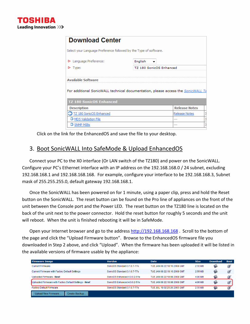
Click on the link for the EnhancedOS and save the file to your desktop.
3. Boot SonicWALL Into SafeMode & Upload EnhancedOS
Connect your PC to the X0 interface (Or LAN switch of the TZ180) and power on the SonicWALL. Configure your PC’s Ethernet interface with an IP address on the 192.168.168.0 / 24 subnet, excluding 192.168.168.1 and 192.168.168.168. For example, configure your interface to be 192.168.168.3, Subnet mask of 255.255.255.0, default gateway 192.168.168.1.
Once the SonicWALL has been powered on for 1 minute, using a paper clip, press and hold the Reset button on the SonicWALL. The reset button can be found on the Pro line of appliances on the front of the unit between the Console port and the Power LED. The reset button on the TZ180 line is located on the back of the unit next to the power connector. Hold the reset button for roughly 5 seconds and the unit will reboot. When the unit is finished rebooting it will be in SafeMode.
Open your Internet browser and go to the address http://192.168.168.168 . Scroll to the bottom of the page and click the “Upload Firmware button”. Browse to the EnhancedOS firmware file you downloaded in Step 2 above, and click “Upload”. When the firmware has been uploaded it will be listed in the available versions of firmware usable by the appliance:

Click the “Uploaded Firmware with Factory Default Settings – New!” boot option to the right. This will upgrade the SonicWALL’s OS and will reboot the unit. The upgrade and reboot process may take up to 3 minutes. Do not power off the SonicWALL during this time.
4. Log into the SonicWALL
When the SonicWALL has completed the upgrade and reboot process, the “Setup Wizard” will launch in a new browser window. Click the Cancel button on the Wizard. This will bring you to the Login prompt. Log in with the default user: admin and password of: password (all lower case).
5. Create the VoIP Zone
Once you are logged in, click on the “Network” tab from the left hand side menu, and navigate to the “Zones” page. When running the EnhancedOS, the SonicWALL Appliance allows for custom zones to be created, allowing for the administrator to choose the “name” of the network segment that is being managed. In this example, we have chosen the zone name of “VoIP” over a zone such as “DMZ”, as you may wish to segment the Voice server from a traditional DMZ that hosts services such as HTTP, FTP, and SMTP. The label of “VoIP” does not impact the SonicWALL’s functionality in any way other than from a management / display function.
Click the “Add…” button to create a new custom zone.
• Name: VoIP
• Security type: Public (This creates a handful of default firewall policies needed for enhanced security)
• Uncheck all options except for “Gateway Anti‐Virus, IPS, and Anti‐Spyware” services (for future use)

Click the “Ok” button. The VoIP Zone is now complete.
6. Create the Toshiba server object
Before configuring the Network Interfaces, an “Object” needs to be created for the Toshiba server. Throughout the EnhancedOS GUI, objects are used by the administrator. An Object can be an IP address, range of IP’s, an IP Network, MAC Address, FQDN, User, Service, Time Schedule, etc… Objects can also be grouped together. The SonicWALL itself maintains a list of objects, such as the interface IP’s. The Administrator can also create custom objects. It is good practice to standardize on the naming scheme for objects to simplify administration.
Similar to the custom Zone name, the naming convention used for the object is to a degree arbitrary. The name does not affect the type or functionality of the actual server. Some Network Administrators prefer to use the IP Address as the name of the Object. Others prefer to use the host name. Some prefer to include more information such as which Zone this object is assigned to. All of these examples are recommended. An example of a poor Object name would be something along the lines of, “Object 1”, “Object 2”, and “Object 3”. It is impossible at first sight to know which server “Object 2” is (Unless the host name of the server was actually “Object 2”). By naming the object relevant (For example,

Email_DMZ), it is easy to quickly identify what server the object represents. See the EnhancedOS Administrator guide for more information about Objects.
In this step we will be creating a custom address object for the Toshiba server.
Navigate to the Network menu, and select “Address Objects”. Scroll to the bottom of the page and click the “Add” button.
• Name: Toshiba_Server_VoIP (“Toshiba_Server” tells the administrator the system name, “_VoIP” tells the administrator which Zone the object is in)
• Zone Assignment: VoIP
• Type: Host
• IP Address: 1.1.1.5
Click the “Ok” button.
7. Configure the X0 (LAN) interface
The next step is to configure the SonicWALL’s X0 (LAN) IP address. Navigate to the Network Menu and select the Interfaces link. In this example, the SonicWALL’s X0 IP is 192.168.168.1 /24. Click the “Configure” button to the far right of the X0 interface.
• Edit the IP Address: from 192.168.168.168 to 192.168.168.1
• In this example, no other changes are needed. Your environment may be different.

Click on the “Advanced Tab”
• Check the “Enable 802.1p tagging” checkbox
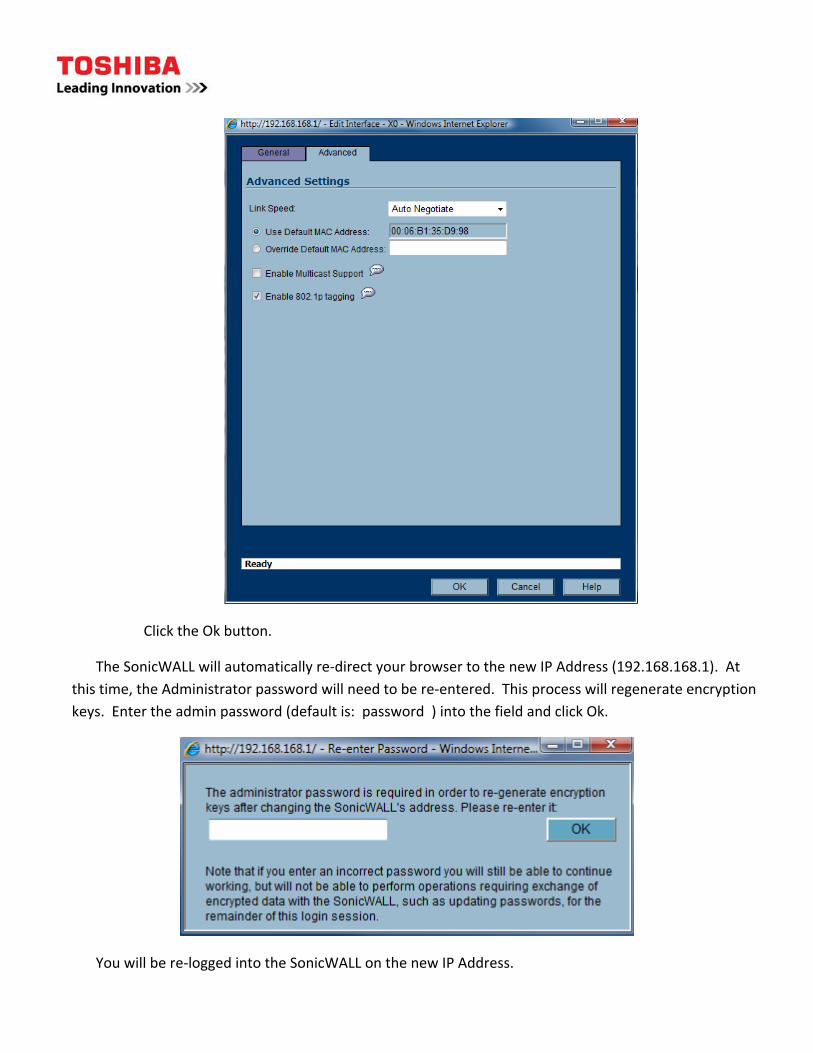
Click the Ok button.
The SonicWALL will automatically re‐direct your browser to the new IP Address (192.168.168.1). At this time, the Administrator password will need to be re‐entered. This process will regenerate encryption keys. Enter the admin password (default is: password ) into the field and click Ok.
You will be re‐logged into the SonicWALL on the new IP Address.

8. Configure the X1 (WAN) interface
As every public Internet connection is unique, your information will be different at every environment. Use the information provided by your ISP to properly configure the public IP settings. The information in this guide is for example only.
Navigate to the Network Menu and select the Interfaces link. In this example, the SonicWALL’s X1 IP is 1.1.1.2 /24. Click the “Configure” button to the far right of the X1 interface.
• Edit the IP Address: from 0.0.0.0 to the IP 1.1.1.2
• Edit the Default gateway to point to 1.1.1.1
• Enter in at least one DNS Server (Public or Private)
• Configure the desired Management options o Check HTTPS if you wish to administer the SonicWALL from the public Internet o Check Ping if you wish to allow hosts on the Internet to ping the WAN’s public IP o Check SSH if you wish to perform limited Command Line Administration from the Internet

Click on the “Advanced” tab:
• Configure the link speed (if desired)
• Click the “Enable 802.1p tagging” checkbox
• Click the “Enable Egress Bandwidth Management” checkbox o Enter your available outbound bandwidth (From the LAN to the Internet)
• Click the “Enable Ingress Bandwidth Management” checkbox o Enter your available inbound bandwidth (From the Internet to your LAN)
Click Ok
9. Configure the X2 (VoIP) interface
The next step is to configure the X2 interface. The X2 interface will be assigned to the VoIP zone and will be in Transparent Mode. When an interface is in transparent mode, the SonicWALL does not perform address translation on packets going out to the Internet from that network segment. Systems configured

on that network segment use a public IP address from the WAN’s IP Segment, and point to the upstream Internet router as the default gateway. The SonicWALL will operate in a layer 3 bridge mode, passing traffic between the two interfaces.
Navigate to the Network menu, and then to the Interfaces link. Click the “Configure” button to the far right of the X2 interface.
• Zone Assignment: VoIP
• IP Assignment: Transparent Mode
• Transparent Range: “Toshiba_Server_VoIP” object
• Comment (Optional): VoIP Network Segment
• Management (Same as Management Options on X0 and X1 interfaces) o HTTPS o Ping
Click the Advanced Tab
• Click the “Enable 802.1p tagging” option

Click Ok
10. Register the SonicWALL
Connect the SonicWALL’s X1 (WAN) interface into the Ethernet port on your internet router. Connect the X0 (LAN) port to the internal switch network. Connect the X2 (VoIP) interface into the Toshiba LIPU.
The SonicWALL should now have Internet access. Navigate to the System menu, and click on the Status link. On the upper right hand section of the GUI, in the Security Services window, click on the link for “Click here to Register your SonicWALL”.

Enter in the mysonicwall.com user name and password used in step 1. This will complete the registration process.
Note, not all services may be licensed for your appliance.
11. Configure Firewall Policies & QoS
The SonicWALL firewall engine is based on Stateful Packet Inspection (SPI). It is important to understand where a TCP session is originating; the return traffic is not as important as SPI will allow the appropriate traffic to return to the originating host. As a reminder, the first packet in a 3‐way TCP handshake is the SYN packet. This is the originating sender; where the traffic is sent “FROM” or “SOURCE”. The return packet, if valid, is a SYN‐ACK. This is where the connection is going “TO” or “DESTINATION”. We do not have to be concerned with writing firewall policies bi‐directional as SPI maintains a connection table for TCP sessions.
The SonicWALL UTM Appliance is configured with default security policies, allowing traffic from more restricted zones to travel to unrestricted zones, but not vice versa.

In example network for this environment, the following security policies are in place between zones:
• LAN ‐> WAN Allowed
• LAN ‐> VoIP Allowed
• VoIP ‐> WAN Allowed
• VoIP ‐> LAN Denied
• WAN ‐> VoIP Denied
• WAN ‐> LAN Denied
As the LIPU is located on the VoIP Zone, and the default policy does not allow networks located in the VoIP zone to initiate communications to networks in the LAN zone, we need to create a firewall policy to allow the traffic. In addition, as voice communications require bandwidth preference on a data network, it is advantageous to prioritize these packets over data packets.
Toshiba’s VoIP implementation uses various protocol sets which are pre‐defined within EnhancedOS in the service group, “VOIP”.
To configure and prioritize communications, click on the Firewall menu and then the Access Rules link. Navigate to the intersection, across the “VoIP” row and down the To column to “LAN” and click configure:
This intersection displays the security policy for traffic originating from the VoIP Zone network(s) to the LAN Zone network(s). There is a single “Deny” rule blocking traffic between both Zones:
Click the Add button to create a new firewall policy:
• Action = Allow
• Service = VOIP
• Source = Toshiba_Server_VoIP

• Destination = LAN Primary Subnet
• Users Allowed = All
• Schedule = Always on
• Comment: Allows VoIP traffic between networks
• Check both “Enable Logging”, and “Allow Fragmented Packets
•
Select the QoS Tab:
• DSCP Markings Action = Explicit
• Explicit DSCP = Explicit DSCP Value = 48 – Control
• 802.1p Marking Action = Explicit
• Explicit 802.1p Value = 6 – Voice (<10ms latency)

Click Ok.
This configuration forces the SonicWALL to explicitly tag VOIP packets with 802.1p and DSCP values. You will need to configure your internal switch environment accordingly.
Configuration Complete
At this point in the configuration, clients on the LAN subnet of the SonicWALL will be able to communicate to the LIPU on the VoIP network, and packets from the LIPU will be prioritized. The SonicWALL is registered and configured with the latest version of EnhancedOS.
Additional information can be found at:
EnhancedOS Admin Guide: http://www.sonicwall.com/us/support/289_6854.html
QoS / Bandwidth Management Guide: http://www.sonicwall.com/us/support/2134_4172.html

Ver 1.18