sonosax sx-st / sx-vt · mode d’emploi sonosax sx-st / sx-vt page 7 de 73 2.2 versions, options...
TRANSCRIPT
PROFESSIONAL MIXING CONSOLE
SONOSAX SX-ST / SX-VT User Manual
Audio equipements manufacturer SONOSAX SAS S.A. Ch. de la Naz 38 1052 Le Mont s/Lausanne SUISSE Tél: +41 21 651 0101 Fax: +41 21 651 0109 Web: www.sonosax.ch Email: [email protected] Version: June 2010
Mode d’emploi SONOSAX SX-ST / SX-VT Page 2 de 73
TABLE OF CONTENT
1. INTRODUCTION.................................................................................................................................................. 5 1.1 Safety Instructions ............................................................................................................................................. 5 2. FIELDS OF APPLICATIONS .............................................................................................................................. 6 2.1 MAIN FEATURES ................................................................................................................................................ 6 2.2 Versions, options and accessories................................................................................................................... 7 2.2.1 SONOSAX SX-ST ................................................................................................................................................ 7 2.2.2 SONOSAX SX-VT ................................................................................................................................................ 7 2.2.3 VCA Mic/Line Input: version with Compressor and optional VCA groups ............................................................. 8 2.2.4 Stereo Line Input: available with or w/o VCA groups ............................................................................................ 8 2.2.5 Digital Module: Analogue to Digital Converter ( Option ) ...................................................................................... 8 2.2.6 Digital Module: 8 track Internal Recorder ( Option ).............................................................................................. 8 2.2.7 Boom Box ( accessory )........................................................................................................................................ 8
3. POWERING.......................................................................................................................................................... 9 3.1 Powering from batteries..................................................................................................................................... 9 3.1.1 Removing the battery compartment...................................................................................................................... 9 3.1.2 Opening the battery compartment ...................................................................................................................... 10 3.1.3 Closing the battery compartment........................................................................................................................ 10 3.1.4 Battery Test ........................................................................................................................................................ 11 3.1.5 Low Battery alarm [LO BATT]............................................................................................................................. 11 3.1.6 Battery charger (option for SX-ST Series only)................................................................................................... 11 3.2 External DC supply ( SX-ST only ) .................................................................................................................. 11 3.2.1 Automatic changeover of the DC power source ................................................................................................. 11 3.3 Main power supply ( SX-VT only ) ................................................................................................................... 12
4. MIC/LINE INPUT MODULE................................................................................................................................ 13 4.1.1 Input selector [ XLR – IN B ] ............................................................................................................................... 14 4.1.2 Direct channel Output [ LINE OUT ] ................................................................................................................... 14 4.1.3 Phantom power [ DYN - 48V ] ........................................................................................................................... 14 4.1.4 Phase reversal [ Ø ] ............................................................................................................................................ 14 4.1.5 Input GAIN setting [ GAIN ] ................................................................................................................................ 15 4.1.6 Limiter (non-VCA version) ................................................................................................................................. 15 4.2 Filtrer and Equalizer ......................................................................................................................................... 15 4.2.1 Sweep Low Frequencies Cut [ LF CUT ] ............................................................................................................ 15 4.2.2 3 bands semi-parametric Equalizer [ EQ ] .......................................................................................................... 16 4.3 Mix busses assignments [ 1 to 8 ]................................................................................................................... 17 4.3.1 Panoramic Potentiometer [ PAN ]....................................................................................................................... 17 4.4 Auxiliary Sends [AUX 1 to 4] ........................................................................................................................... 18 4.4.1 AUX busses assignment [ PRE–OFF–POST ] ................................................................................................... 18 4.4.2 Channel fader ..................................................................................................................................................... 18 4.4.3 Level switch [12 - 24] .......................................................................................................................................... 18 4.4.4 Dual Peak Level Meters...................................................................................................................................... 18 4.4.5 On / Mute Key [ ON ] .......................................................................................................................................... 19 4.4.6 PFL/AFL Pre-Listening [ P/A ]............................................................................................................................ 19 4.4.7 Channel power on switch [PWR –ON])............................................................................................................... 19 4.5 VCA groups selector (modules with VCA only) ............................................................................................. 20 4.6 Compressor (modules with VCA only) ........................................................................................................... 20 4.6.1 Threshold............................................................................................................................................................ 20 4.6.2 Ratio ................................................................................................................................................................... 20 4.7 On Air Signalling (SX-VT only) ........................................................................................................................ 20 4.8 Fonction MUTE ................................................................................................................................................. 20
Mode d’emploi SONOSAX SX-ST / SX-VT Page 3 de 73
5. STEREO LINE INPUT MODULE ....................................................................................................................... 21 5.1 Left & Right gain controls................................................................................................................................ 22 5.2 Selector [ MONO ]............................................................................................................................................. 22 5.3 Stereo Equalizer [ EQ ]..................................................................................................................................... 22 5.4 Auxiliary Sends [AUX 1] to [AUX 4] ................................................................................................................ 22 5.4.1 Auxiliary routing switches [PRE-OFF-POST]...................................................................................................... 22 5.5 Dual Peak level meter....................................................................................................................................... 23 5.6 Assignment to mix busses 1/2 to 7/8............................................................................................................. 23 5.6.1 Channel Fader.................................................................................................................................................... 23 5.6.2 Left – Right Balance [ BAL ]................................................................................................................................ 23 5.6.3 On / Mute Key [ ON ] .......................................................................................................................................... 24 5.7 Fader Start [ REMOTE ] ................................................................................................................................... 24 5.8 PFL/AFL Pre-Listening [ P/A ]......................................................................................................................... 24 5.9 VCA groups selector (optional on SX-VT Series only).................................................................................. 24
6. MASTER AND MONITORING MODULE........................................................................................................... 25 6.1.1 METERING......................................................................................................................................................... 26 6.1.2 Meter's operating mode [ ST-M-Low Batt ] ......................................................................................................... 26 6.1.3 Meter's backlight [ BACK ] .................................................................................................................................. 26 6.1.4 Led's operating mode [ LEDS ] ........................................................................................................................... 26 6.1.5 Signalling Leds [ ON AIR ] and [ MUTE ] (SX-VT only) .................................................................................... 26 6.2 Talkback/SLATE and Oscillator....................................................................................................................... 27 6.2.1 Source Selector [ MIC-OSC-FIX ]...................................................................................................................... 27 6.3 Pre listening Selector [ PFL-AFL-SOLO ] ....................................................................................................... 27 6.3.1 P/A operating mode [ Normal-Reset ] ................................................................................................................. 27 6.4 Powering ON/OFF............................................................................................................................................. 27 6.5 Return lines 1 to 8 [ RETURN ] ........................................................................................................................ 28 6.5.1 Return's Master Level......................................................................................................................................... 28 6.5.2 Return's Pre-Listening [ P/A RET ] ..................................................................................................................... 28
6.6 MONITORING .................................................................................................................................................... 28 6.6.1 Monitor Source Selector ..................................................................................................................................... 28 6.6.2 Monitor Mode selector ........................................................................................................................................ 28 6.6.3 Headphone volume [ PHONE 1 ] to [ PHONE 3 ] ............................................................................................... 29 6.7 Communication and Private Lines [ COM – PL1 – PL2 ] .............................................................................. 29 6.7.1 Comm. Monitor Attenuation ................................................................................................................................ 29 6.7.2 [ Mic 1 ] to [ Mic 3 ] ............................................................................................................................................. 29 6.7.3 Side Tone ........................................................................................................................................................... 29
6.8 MASTER SECTION ........................................................................................................................................... 30 6.8.1 GROUP Masters................................................................................................................................................. 30 6.8.2 AUX Masters ...................................................................................................................................................... 30 6.8.3 Modulomètre à 5 Leds ........................................................................................................................................ 30 6.8.4 Key [ P/A ] .......................................................................................................................................................... 31 6.8.5 Commutateurs [ Talkback-Off-Return ] ............................................................................................................... 31
Mode d’emploi SONOSAX SX-ST / SX-VT Page 4 de 73
7. DIGITAL MODULE: A/D CONVERTER & INTERNAL 8 TRACKS RECORDER............................................ 32 7.1 A/D Converter ................................................................................................................................................... 33 7.1.1 Sourcing selector [IN 1 MIX] to [IN 8 MIX] .......................................................................................................... 33 7.1.2 Red led indicator [ L/O ] ...................................................................................................................................... 33 7.1.3 Protection Limiter's [ LIMITERS ]........................................................................................................................ 33 7.1.4 Sampling frequencies ......................................................................................................................................... 33 7.1.5 Clocking and Sync.............................................................................................................................................. 34 8. INTERNAL RECORDER.................................................................................................................................... 35 8.1 CONNECTIONS ................................................................................................................................................. 35 8.1.1 Port USB 2.0....................................................................................................................................................... 35 8.1.2 Remote Connector [ REMOTE ] ......................................................................................................................... 35 8.1.3 Time Code Connector [ TC ]............................................................................................................................... 35 8.1.4 Sync Connector [ VIDEO IN ] ............................................................................................................................. 35 8.2 PRINCIPLE OF OPERATION ............................................................................................................................ 36 8.2.1 User Interfaces ................................................................................................................................................... 36 8.2.2 ARCHITECTURE - Audio path ........................................................................................................................... 38 8.3 TRACKS MONITORING .................................................................................................................................... 39 8.3.1 Monitoring Level ................................................................................................................................................. 39 8.3.2 Solo Monitoring................................................................................................................................................... 40 8.4 MENUS CONTEXTUELS................................................................................................................................... 41 8.5 MONITORING .................................................................................................................................................... 42 8.6 LAST TAKE ....................................................................................................................................................... 43 8.6.1 PLAYER Mode ................................................................................................................................................... 44 8.6.2 SEARCH mode................................................................................................................................................... 45 8.6.3 Contextual menu in mode [PLAYER].................................................................................................................. 46 8.7 Unit STATUS ..................................................................................................................................................... 46 8.8 SETUP (Configuration's Menus)...................................................................................................................... 48 8.8.1 Tree structure of the "SETUP" menus ................................................................................................................ 49 8.8.2 ROUTING SETTING .......................................................................................................................................... 50 8.8.3 RECORD SETTINGS ......................................................................................................................................... 51 8.8.4 TIME CODE SETTINGS..................................................................................................................................... 54 8.8.5 MODULOMETERS............................................................................................................................................. 55 8.8.6 USER SETTINGS............................................................................................................................................... 55 8.8.7 SYSTEM SETTINGS.......................................................................................................................................... 56 8.8.8 MISC (Miscellaneous)........................................................................................................................................ 57 8.9 BROWSE FILES ................................................................................................................................................ 58 9. MANAGING THE RECORDER.......................................................................................................................... 60 9.1.1 Formatting the HardDisk and CompactFlash card.............................................................................................. 60 9.1.2 Fragmentation de l'espace libre du disque dur ................................................................................................... 60 9.1.3 USB 2.0 connection............................................................................................................................................ 61 9.1.4 Alarmes .............................................................................................................................................................. 62 9.1.5 Traitement des erreurs ....................................................................................................................................... 62 9.1.6 Up-date procedure.............................................................................................................................................. 63 9.1.7 Recommendations.............................................................................................................................................. 63 10. ANNEXES .......................................................................................................................................................... 64 11. SPECIFICATIONS ............................................................................................................................................. 68
Mode d’emploi SONOSAX SX-ST / SX-VT Page 5 de 73
1. INTRODUCTION
Congratulations, by choosing the professional mixing console SONOSAX SX-ST or SONOSAX SX-VT, you have acquired a high quality product, designed and built to last for many years with outstanding performances
The SONOSAX SX-ST and SONOSAX SX-VT are modular audio mixing consoles among the most compact of the market. Although small in size, they offer many features and a wide choice of configurations to suit the needs of each user.
As for any SONOSAX products, the SX-ST and SX-VT mixing console are built without any compromise in quality. Our 30 years of experience have helped us to develop and build this console which is designed to have a lifespan of at least 12 to 15 years. The reliability of SONOSAX product is the result of a high technology design, a selection of the best available components, a meticulous hand assembly and a severe quality control
Each of the circuits has been intensively studied to reach a very high level of performance with the lowest possible power consumption. The result of this research and development is an ergonomic mixer, very reliable and offering unsurpassed performances to date.
1.1 Safety Instructions
• Read all the safety and operation instructions before operating the SX-ST / SX-VT console and its power supply.
• Keep the instructions for further reference.
• Please pay attention to all warnings, notes and instructions in this operation manual.
• Keep the SX-ST / SX-VT console and its power supply away from heat sources such as radiators or other devices that produce heat.
• Connect the SX-ST / SX-VT mixing console only to the optional external power supply delivered by SONOSAX. Route power supply cords so that they are not likely to be walked on or pinched by items placed on or against them, paying particular WARNING to cords at plugs, inlets and the point where they exit the console. Keep power cords away from audio cords.
• Do not drop objects or spill liquids onto the audio mixer and its power supply.
• The audio mixing console and its external power supply should be serviced only by qualified service personnel as your nearest SONOSAX authorized reseller.
• Do not change the polarity of the DC power supply of the SX-ST
• Line voltage selectors should only be resettled and equipped with a proper plug for alternate voltage by a qualified service technician.
• To reduce the risk of fire or electric shock, do not expose this appliance to rain or moisture.
• Internal settings and adjustments must be solely executed by an authorized SONOSAX distributor or at factory.
• Any damage caused by inappropriate manipulations inside the unit immediately cancels the SONOSAX limited warranty.
Mode d’emploi SONOSAX SX-ST / SX-VT Page 6 de 73
2. FIELDS OF APPLICATIONS
The SONOSAX SX-ST and SONOSAX SX-VT are a line of compact, easily transportable, self-contained mixing consoles, providing all features required to meet the needs of professionals in mobile and studio applications.
Built in a strong, rugged and anodised aluminium chassis, the SONOSAX SX-ST and SX-VT series provide the best choice whenever top performances, small size, light weight and low power consumption are important.
Thanks to their modularity, the numbers of functionalities and the wide range of possible configurations, the SONOSAX SX-ST and SX-VT mixing console are ideal for many applications, such as:
• Video, Television and cinematography productions.
• High quality analogue or digital recording of acoustical music.
• OB Vans, Live Broadcasting, sports or any live events.
• Mobiles or stationary recording facilities or post production systems.
• High end installations for concert halls, theatres, cinemas.
2.1 MAIN FEATURES
• Compact and modular construction.
• Choices of housing and configurations to meet the each user's needs and requirements.
• Choice of components without compromise, switches, knobs and faders linear conductive plastic high quality.
• Electronically balanced, transformer less inputs and outputs.
• Very wide bandwidth ranging from 10Hz to over 200kHz, and high overall dynamic perfectly suitable for SACD and A/D converters of the latest generation.
• Extremely low noise microphone preamplifiers with large gain range, using "semi discrete" technology.
• 48V Phantom power, polarity reversal and individual Limiter on each input module.
• Progressive LF Cut and 3 band semi-parametric equalizer.
• Direct channels outputs internally configurable Pre-EQ, Post-EQ or Post-Fader.
• 8 mix busses individually assignable Pre-Fader / Post-Pan or Post-Fader / Post-Pan.
• 4 Auxiliaries busses individually assignable Pre-Fader or Post-Fader.
• Double 5 Led's peak meters showing both Pre and Post fader level.
• 8 Master groups with Slate and return's re-injection facilities.
• Triple Monitoring section with 2 Private Line for communication.
• Large scale level-meter switch able as level meter and phase correlation meter
• Optional high resolution Analogue to Digital converter.
• Optional internal 8 track recorder on Hard disk and CF Card.
• Powering by internal batteries or any external DC supply from 11 to 18VDC ( SX-ST only).
• Low power consumption, light weight and small foot print.
Mode d’emploi SONOSAX SX-ST / SX-VT Page 7 de 73
2.2 Versions, options and accessories
The SONOSAX SX-ST and SX-VT SONOSAX mixing consoles are based on a modular concept, offering a wide variety of configurations to fit closer to the demands and needs of each user. Thus each model of the SX-ST or SX-VT series is available in choice of predefined sizes and formats and can be fitted with different modules available in this range.
The frames are always fully pre-wired for the maximum possible number of input modules, so it is possible to configure a console with a small number of modules and add further input channels or additional available options at a later date.
Whatever the model chosen, the Master & Monitoring module are the same for each version. This module always contains the 8 Master outputs, 4 Auxiliary outputs, and the triple monitoring section with two lines of private communication. The SX-ST also contains the DC/DC converter that provide all the internal supply voltages.
2.2.1 SONOSAX SX-ST
The SONOSAX SX-ST series is available in three different size of housing:
- SX-ST8D: up to 8 input modules and one additional slot for the optional Digital module ( A/D Converter and Internal Recorder.
- SX-ST10: up to 10 input modules, or 9 input modules and one digital module.
- SX-ST12: up to 12 input modules, or 11 input modules and one digital module.
The SX-ST8D and SX-ST10 are available either as "Standard" version or as "Compact" version:
- "Standard" version: is built with a removable battery compartment on the front, the console can be powered from this battery compartment and from an external DC supply. Extra battery compartment can be ordered separately for a quick exchange when a production is in progress.
- "Compact" version: does not hold the battery compartment, thus it is reduced in depth offering a smaller foot print. The console can only be powered from an external DC supply.
NOTE: The SX-ST12 is only available as "Compact" version. Given the limits of electrical loads of the internal DC/DC converter, installing input module with VCA in the SX-ST12 may not be possible. Please check with your local distributor or directly from SONOSAX to check if the desired configuration is technically possible.
2.2.2 SONOSAX SX-VT
The SONOSAX SX-VT series is based on the same technologies as the SX-ST, but is available in larger configurations with numbers of inputs ranging from 12 to 48. Because of its larger size and for reasons of mechanical stability, the SX-VT series is built on a frame made of different profiles from those of the SX-ST series, which also allows greater flexibility in configuring the rear connector panel.
The input modules and the Master & Monitoring module are identical, but the greater number of input modules requires a dedicated external power supply. The SX-VT mixers can only be powered by their own power supply.
The external power supply has a voltage selector to adapt to the different global networks 110/120VAC or 220/240VAC, 47-64Hz, allowing use of the console in the world without any other change.
For OB Van applications or mobile set up, we can provide a special DC/AC converter (UPS) to power the console from the vehicle battery (12V or 24V).
In general, each SONOSAX SX-VT mixer is built to specifications provided by the future user. Thus the size, type of terminal and connector are defined in accordance with the user to adapt as closely as possible to its specific needs.
Mode d’emploi SONOSAX SX-ST / SX-VT Page 8 de 73
2.2.3 VCA Mic/Line Input: version with Compressor and optional VCA groups
The SX-ST and SX-VT mixing consoles can be equipped with a VCA Mic/Line input (Voltage Controlled Amplifier) featuring Compressor instead of the usual Limiter. This Compressor is a particular type which avoids the so called "pumping" effect which is frequently found on this type of circuit. The user is thus assured at all times, especially when working with digital systems that no saturation will occur.
On SONOSAX SX-VT only, this version can be completed by VCA grouping system comprising a VCA Group selector and Master modules for the VCA group. An optional Sub-D25 can connector can be installed to allow controlling the VCA by an external voltage (such as an editing or automation system) to externally the level of each input module individually.
- see also detailed descriptions at chapter xxx
2.2.4 Stereo Line Input: available with or w/o VCA groups
A Stereo Line Input module is also available for SX-ST and SX-VT.
This module allows connection to any stereo or dual-channel input at line level. Volume controls and panning are also based on a technology VCA. Thus, this option may not be available on all models of the SX-ST series due to its power consumption.
- see also detailed descriptions at chapter xxx
2.2.5 Digital Module: Analogue to Digital Converter ( Option )
An high quality 8-channels Analogue/Digital is available as an option, providing with 4x AES/EBU digital outputs corresponding to these 8-channel. It offers all the sampling frequencies from 44.1 kHz to 192 kHz with a resolution of 24 bits. A switching system allows the conversion of either direct outputs of the channels or the Group master outputs.
- see also detailed descriptions at chapter xxx
2.2.6 Digital Module: 8 track Internal Recorder ( Option )
An 8-track recorder on hard disk and CompactFlash card is also available as an option. It is integrated directly into the Digital Module allows digital recording in BWF format of the 8 channels available at the output of A/D converter. It provides with all the features expected on modern recorder such as TimeCode management, meta data tags etc. It comes with a remote control to configure all the parameters and the recorder
- see also detailed descriptions at chapter xxx
2.2.7 Boom Box ( accessory )
A small box with belt clip used for monitoring and communication, is available under reference SX 022260. This box is commonly called "Boom Box is used to provide a return monitoring and a communication line to the boom operator. It may also be useful in other cases such as communication with a speaker cabin or a video control room in a small mobile unit for example. A special cable of 25 meters is also available as an accessory, other length on request.
Mode d’emploi SONOSAX SX-ST / SX-VT Page 9 de 73
3. POWERING
The SONOSAX SX-ST mixer can be powered either by an external stabilized DC power source 11 to 18VDC or by the battery compartment located on the front. (SX-ST8D & SX-ST10 only).
3.1 Powering from batteries
The standard version of SX-ST8D and SX-ST10 can be powered by the removable battery compartment attached to the front. It contains 12 batteries of type LR20 (type D) Nickel Metal Hydride (NiMH) or Nickel Cadmium (NiCd), and possibly with alkaline or lithium batteries
The power switch is located on the Master module on the right side of the lowest modulometer. Place the switch to [POWER] to turn on the mixer. The green LED located above the switch lights up in 2 or 3 seconds. If the console does not light up:
Check if the batteries are properly installed and that the polarity is correct. Check that the battery compartment door is closed and the compartment properly locked in place. Make sure the batteries are properly charged (batteries, even new, may have a manufacturing
defect)
The theoretical running time with 12x 10Ah NiMH rechargeable batteries will be around 4-6 hours, it depends on the number of input channel being switched On, the type and number of microphones used, the presence of the integrated recorder and of course the quality of batteries.
Because of their chemical composition, the internal resistance of NiMH rechargeable batteries does not vary upon the current drawn, thus allowing harness of their full capacity (which is not the case with Alkaline batteries) therefore it is recommended to use rechargeable NiMH rather than alkaline batteries. The use of rechargeable batteries is also more environmentally friendly than the use of disposable batteries.
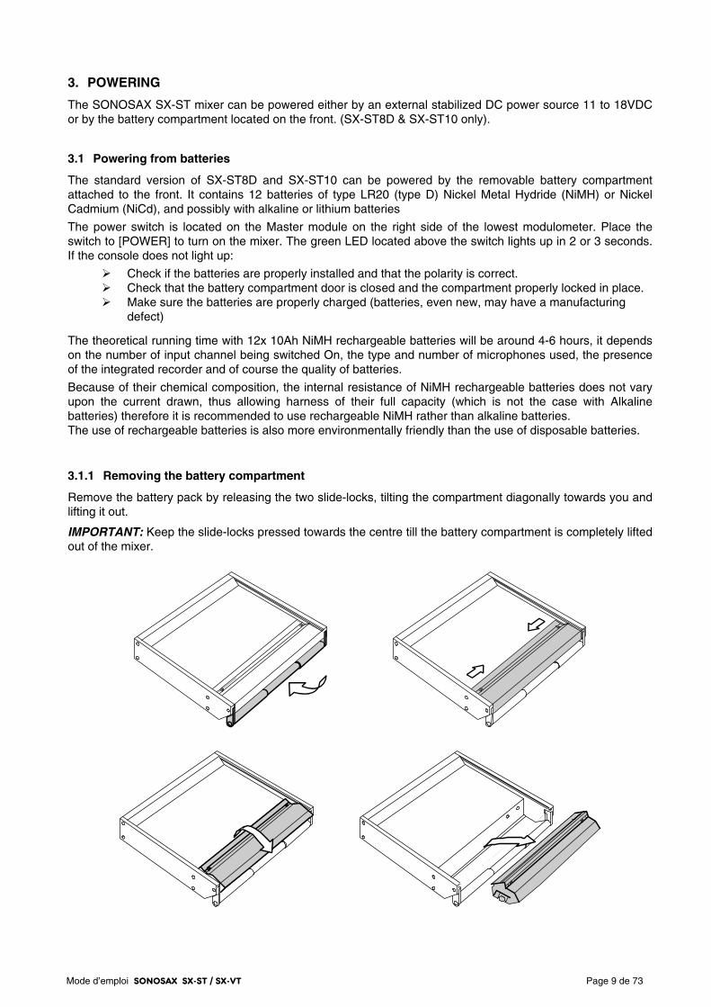
3.1.1 Removing the battery compartment
Remove the battery pack by releasing the two slide-locks, tilting the compartment diagonally towards you and lifting it out.
IMPORTANT: Keep the slide-locks pressed towards the centre till the battery compartment is completely lifted out of the mixer.
Mode d’emploi SONOSAX SX-ST / SX-VT Page 10 de 73
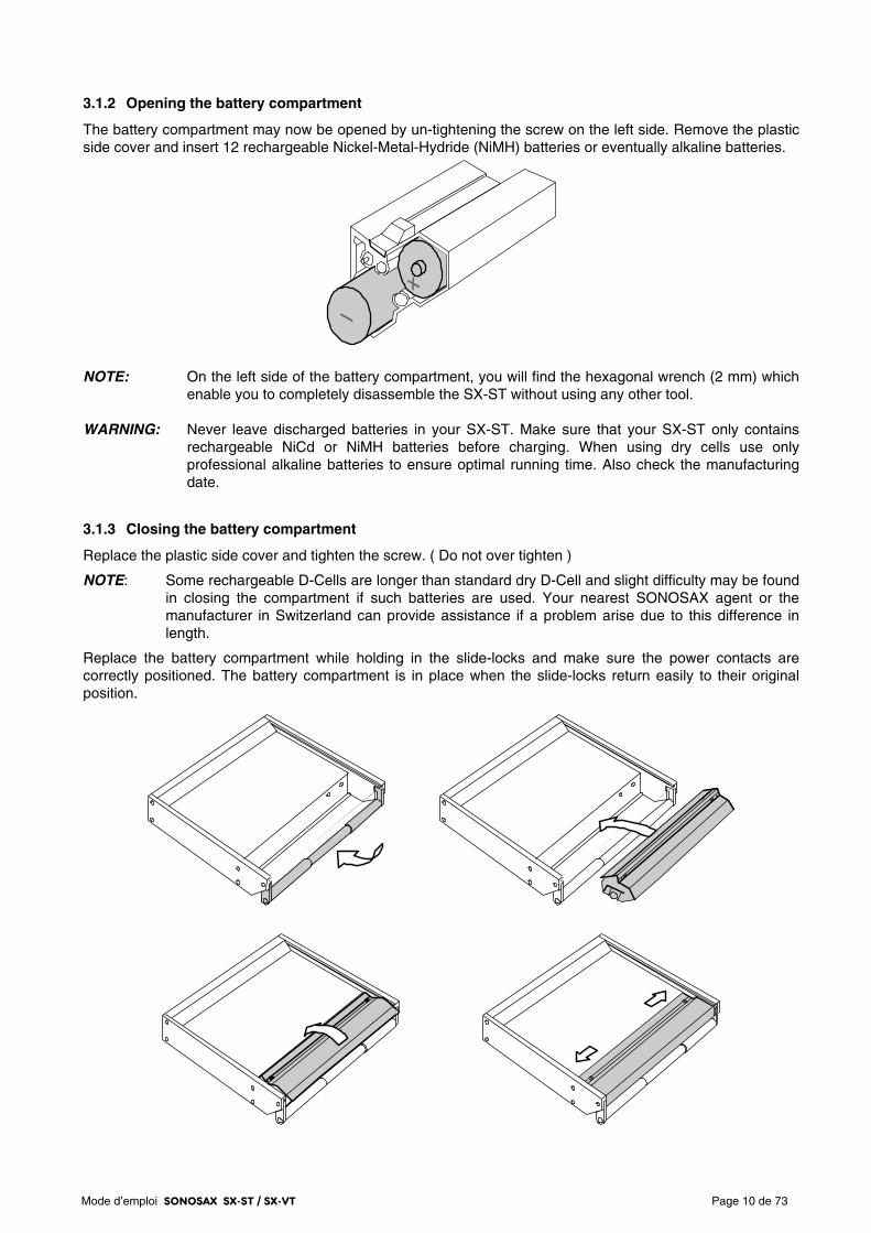
3.1.2 Opening the battery compartment
The battery compartment may now be opened by un-tightening the screw on the left side. Remove the plastic side cover and insert 12 rechargeable Nickel-Metal-Hydride (NiMH) batteries or eventually alkaline batteries.
NOTE: On the left side of the battery compartment, you will find the hexagonal wrench (2 mm) which
enable you to completely disassemble the SX-ST without using any other tool. WARNING: Never leave discharged batteries in your SX-ST. Make sure that your SX-ST only contains
rechargeable NiCd or NiMH batteries before charging. When using dry cells use only professional alkaline batteries to ensure optimal running time. Also check the manufacturing date.
3.1.3 Closing the battery compartment
Replace the plastic side cover and tighten the screw. ( Do not over tighten )
NOTE: Some rechargeable D-Cells are longer than standard dry D-Cell and slight difficulty may be found in closing the compartment if such batteries are used. Your nearest SONOSAX agent or the manufacturer in Switzerland can provide assistance if a problem arise due to this difference in length.
Replace the battery compartment while holding in the slide-locks and make sure the power contacts are correctly positioned. The battery compartment is in place when the slide-locks return easily to their original position.
Mode d’emploi SONOSAX SX-ST / SX-VT Page 11 de 73
3.1.4 Battery Test
The switch [Lo Batt - M - T] located below the level meters lets control the charge of the batteries. When depressed toward its momentary position, the lower level meter will indicate the average voltage per cell between 0.9 V and 1.6 V
3.1.5 Low Battery alarm [LO BATT]
When the average voltage per cell reaches 1.05V, the [Low Batt] Led will automatically start blinking. This alarm means that about 10 to 20 minutes of use remain available before the mixer automatically turns off. This auto-shut down protects the accumulators from excessive discharge
3.1.6 Battery charger (option for SX-ST Series only)
An external NiCd or NiMH battery charger is available for the SX-ST Series. (part nr SX 008415 ) You do not need to remove the cells from the battery compartment to individually recharge the batteries. A connector located at the right side of the battery compartment is provided to recharge all 12 cells at once. Simply remove the battery compartment as described at section 2.2.1 and connect appropriate charger to the battery pack
WARNING: - Never attempt to charge alkaline D-Cell batteries ( high risk of explosion !!) - Charger must be suitable for 14,4 V batteries. - Make sure that your NiCd or NiMh batteries accept high current charge when using a fast charger
3.2 External DC supply ( SX-ST only )
The SONOSAX SX.ST can be powered from any regulated DC power supply or from an external battery bank ranging from 11 to 18 Volts and capable of delivering at least 2.5Amp. The average power consumption is approximately 16 to 24Watts depending of its configuration, which represents approx 2Amp under 12V.
The mixer is delivered with a universal AC/DC main adapter accepting a voltage range from 100 to 260V AC, 50Hz to 60Hz. Thus it can be used worldwide without any modification or adjustment. A spare power is available from your dealer or SONOSAX under reference number: SX-008450.
The DC connector [DC IN] is located on the rear panel.
The mating cable connector is a XLR4-F
Pin 1 = GND or negative / Pin 4 = +11 to +18VDC or positive
Connect the external power supply to the [DC IN] located on the rear panel. Turn the switch to [POWER] to turn on the mixer. The green LED should light. If it does not light:
Check that the external voltage is between 11 et 18V DC. Check that your power supply can sustain at least. 40 watts Check that the DC plug is correctly wired.
3.2.1 Automatic changeover of the DC power source
The internal DC/DC converter circuitry is designed to automatically changeover between the internal batteries and the external DC power supply. Turning OFF the console to change the power source is not necessary.
While turning on the mixer, when an external DC power supply is connected and the batteries are installed, the internal DC/DC converter will automatically switch on the external DC. If the external DC supply fails or if the voltage drops below 10.5 VDC then the DC/DC converter will automatically switch over to the internal batteries.
When the battery voltage drops below 1.00V per cell, the DC/DC converter will switch automatically to the external DC power supply, providing that the external DC source was connected after powering On the console.
NOTE: the switch over is absolutely silent, no noise, pops or clicks during will be heard
Mode d’emploi SONOSAX SX-ST / SX-VT Page 12 de 73
3.3 Main power supply ( SX-VT only )
The SONOSAX SX-VT mixing consoles are comes with their dedicated external main power supply and should not be used with a power supply other than that supplied with the original mixer
The external power supply is designed to accept line voltages between 100 and 260V, 47-64 Hz. A voltage switch located on the rear of the housing allows selection of different voltages 110/120VAC or 220/240VAC.
WARNING: Make sure the voltage selector matches the local voltage BEFORE connecting the main cable to the power supply
The power supply is connected to the network by mean of a standard IEC socket that meets all international safety standards. Make sure the cord is properly grounded. For your own safety, it is recommended not to remove the ground connection or fail to make this connection.
Mode d’emploi SONOSAX SX-ST / SX-VT Page 13 de 73
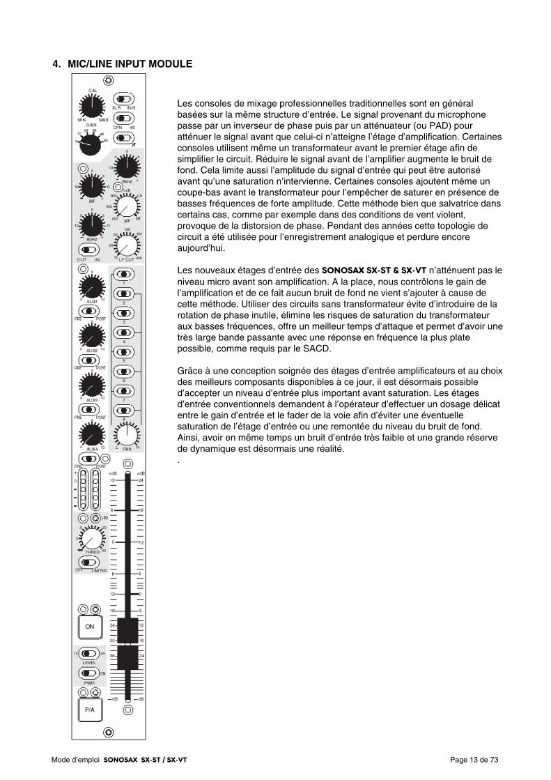
4. MIC/LINE INPUT MODULE
Les consoles de mixage professionnelles traditionnelles sont en général basées sur la même structure d’entrée. Le signal provenant du microphone passe par un inverseur de phase puis par un atténuateur (ou PAD) pour atténuer le signal avant que celui-ci n’atteigne l’étage d’amplification. Certaines consoles utilisent même un transformateur avant le premier étage afin de simplifier le circuit. Réduire le signal avant de l’amplifier augmente le bruit de fond. Cela limite aussi l’amplitude du signal d’entrée qui peut être autorisé avant qu’une saturation n’intervienne. Certaines consoles ajoutent même un coupe-bas avant le transformateur pour l’empêcher de saturer en présence de basses fréquences de forte amplitude. Cette méthode bien que salvatrice dans certains cas, comme par exemple dans des conditions de vent violent, provoque de la distorsion de phase. Pendant des années cette topologie de circuit a été utilisée pour l’enregistrement analogique et perdure encore aujourd’hui. Les nouveaux étages d’entrée des SONOSAX SX-ST & SX-VT n’atténuent pas le niveau micro avant son amplification. A la place, nous contrôlons le gain de l’amplification et de ce fait aucun bruit de fond ne vient s’ajouter à cause de cette méthode. Utiliser des circuits sans transformateur évite d’introduire de la rotation de phase inutile, élimine les risques de saturation du transformateur aux basses fréquences, offre un meilleur temps d’attaque et permet d’avoir une très large bande passante avec une réponse en fréquence la plus plate possible, comme requis par le SACD. Grâce à une conception soignée des étages d’entrée amplificateurs et au choix des meilleurs composants disponibles à ce jour, il est désormais possible d’accepter un niveau d’entrée plus important avant saturation. Les étages d’entrée conventionnels demandent à l’opérateur d’effectuer un dosage délicat entre le gain d’entrée et le fader de la voie afin d’éviter une éventuelle saturation de l’étage d’entrée ou une remontée du niveau du bruit de fond. Ainsi, avoir en même temps un bruit d’entrée très faible et une grande réserve de dynamique est désormais une réalité. .
Mode d’emploi SONOSAX SX-ST / SX-VT Page 14 de 73
4.1.1 Input selector [ XLR – IN B ]
The mono Mic/Line input accepts connection of any type of dynamic or condenser microphone or any external analogue source at line level. The inputs are electronically balanced type without transformer.
Each input provides with two different type of connections: a conventional XLR-3F receptacle and the “B” input on a multi-ways 25pin Sub-D connector [IN B 1-8]. This is useful when different sources are frequently swapped (e.g. a set of microphones and a multi-track recorder/player) or when a set of microphones are connected using a stage box and a multi-ways cable.
Position XLR: XLR-3F connector is selected Pin1 = Gnd / Pin2 = High (+) / Pin3 = Low (-).
Position IN B: the 25pin Sub-D connector is selected (please refer to the wiring diagram)
To connect an unbalanced source such as CD Player, Minidisk or else, pin 3 must be bridged to pin 1 (Gnd) and wired to the Gnd of the source. Then use pin 2 for the unbalanced input signal.
WARNING: Never use the [48V] Phantom in case of unbalanced connection or you could severely damage the source!
NOTE: The 25pin Sub-D connector is NOT a Line level input only, it provides with the same facilities
as on the XLR’s like phantom power and phase reverse. The wiring conforms to most popular equipments to allow the use of “standard” ready made multi-ways cables.
4.1.2 Direct channel Output [ LINE OUT ]
Each input channel has a direct output whose source can be taken either EQ Pre or Post EQ or Post Fader. The selection is done through an internal switch on the circuit board.
The direct channel outputs are at line level, electronically balanced transformer-less. They are available on the connector 25-pin D-Sub [LINE OUT] on the rear panel. Please refer to the wiring diagram in the addendum for the pin out of this connector.
4.1.3 Phantom power [ DYN - 48V ]
This switch enables or disables the 48Volts phantom power on the corresponding channel. Position DYN: 48V phantom power is OFF – for use with dynamic microphones or line input. Position 48: 48V phantom power is ON – for use with condenser microphones. WARNING: - Never use the 48V Phantom in case of unbalanced.
- Never use the 48V Phantom when an external device other than a condenser microphone is connected to the input or you may severely damage the output circuitries of that device. - The 48V will be applied to either to the XLR or to the [INPUT B] according to the Input Select switch. Caution must be taken when equipments other than a condenser microphone are connected to the 25pin Sub-D.
NOTE: The latest generations of microphones operate almost exclusively with 48 V Phantom, as this mode provides an excellent common mode rejection (CMRR), only this mode of microphone powering is available on the SX-ST / SX-VT. Adapters to convert 48V phantom to T12 or P12 are made available by some microphone manufacturers.
4.1.4 Phase reversal [ Ø ]
This switch reverses the polarity of the input signal, which corresponds to a phase rotation by 180 degrees.
It can be used to correct a reversed cable wiring or to address a phase problem between two microphones due to their placement while recording in stereo. It can also be used to progressively decode a M/S signal on a three ways decoding method.
Mode d’emploi SONOSAX SX-ST / SX-VT Page 15 de 73
4.1.5 Input GAIN setting [ GAIN ]
The primary input stage allows a wide range of input gain adjustment, ranging from -20dB to +80 dB. The maximum allowable input level is +25 dBu.
The input gain is precisely controlled in two steps by mean of a rotary switch and a potentiometer; the rotary switch sets a primary gain of 0, 12, 24, 36, 48 or 60 dB. Then, the potentiometer (also called TRIM) is used for a progressive and fine gain adjustment within a range of -20dB to +20 dB from the centre CAL position.
An additional +12dB or +24dB of gain is available on the linear Fader (see next chapter).
NOTE: the overall gain range is quite wide and therefore the gain must be adjusted with cautions. Check the input level using the Pre-Fader Level Meter and/or activate the PFL. An excessive gain will leave little with headroom and can lead to clipping. On the opposite, a level set too low will lead to a poor signal to noise ratio.
4.1.6 Limiter (non-VCA version)
Each input channels has its own independent Limiter which is part of the microphone pre-amplifier circuitries. It is engaged by the switch [OFF – LIMITER].
The potentiometer [THRES] sets the threshold level above which the limiter becomes active. The threshold can be adjusted between infinite and - 30dB below the nominal level. The attack time is very fast (half sine wave only) and the release time depends of the modulation's program.
The activity of the limiter is indicated by the green Led located just above the potentiometer. It lights up as soon as the Threshold level is reached. As long as the LED remains dark, the Limiter is inactive and has absolutely no effect on the audio signal.
NOTE: To protect the input circuitries and to avoid clipping, the Limiter will be automatically activated 2dB before clipping even if the Limiter switched Off or set to "infinite". This feature also provide with an additional 8dB of headroom before clipping.
4.2 Filtrer and Equalizer
The SONOSAX SX-ST / SX-VT input module is equipped with a powerful filtering and equalization section. Its design is derived from our previous model SONOSAX SX-S on which the efficiency and sonic integrity have been well proven in practice for decades.
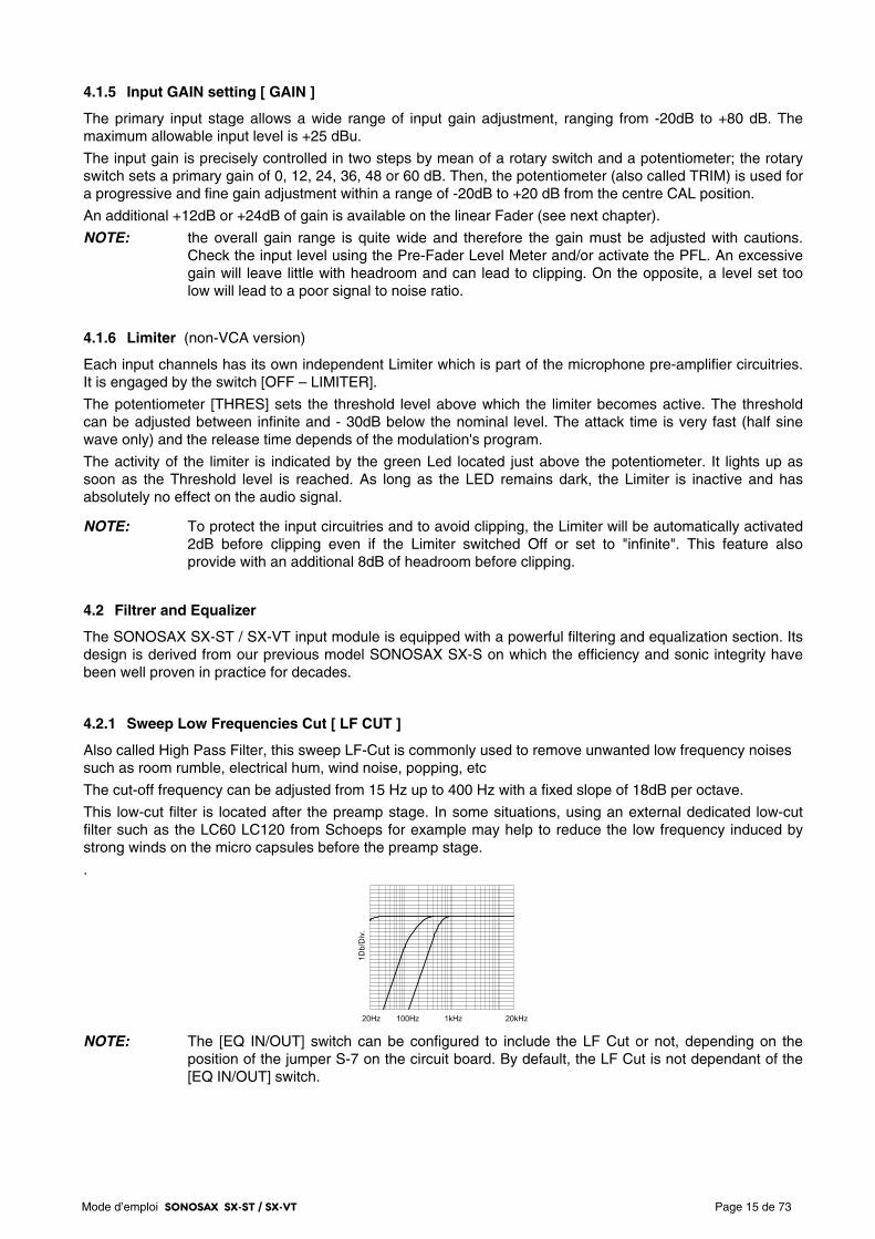
4.2.1 Sweep Low Frequencies Cut [ LF CUT ]
Also called High Pass Filter, this sweep LF-Cut is commonly used to remove unwanted low frequency noises such as room rumble, electrical hum, wind noise, popping, etc
The cut-off frequency can be adjusted from 15 Hz up to 400 Hz with a fixed slope of 18dB per octave.
This low-cut filter is located after the preamp stage. In some situations, using an external dedicated low-cut filter such as the LC60 LC120 from Schoeps for example may help to reduce the low frequency induced by strong winds on the micro capsules before the preamp stage.
.
NOTE: The [EQ IN/OUT] switch can be configured to include the LF Cut or not, depending on the position of the jumper S-7 on the circuit board. By default, the LF Cut is not dependant of the [EQ IN/OUT] switch.
Mode d’emploi SONOSAX SX-ST / SX-VT Page 16 de 73
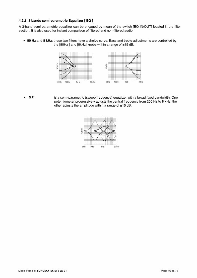
4.2.2 3 bands semi-parametric Equalizer [ EQ ]
A 3-band semi parametric equalizer can be engaged by mean of the switch [EQ IN/OUT] located in the filter section. It is also used for instant comparison of filtered and non-filtered audio.
• 80 Hz and 8 kHz: these two filters have a shelve curve. Bass and treble adjustments are controlled by the [80Hz ] and [8kHz] knobs within a range of ±15 dB.
• MF: is a semi-parametric (sweep frequency) equalizer with a broad fixed bandwidth. One potentiometer progressively adjusts the central frequency from 200 Hz to 8 kHz, the other adjusts the amplitude within a range of ±15 dB.
Mode d’emploi SONOSAX SX-ST / SX-VT Page 17 de 73
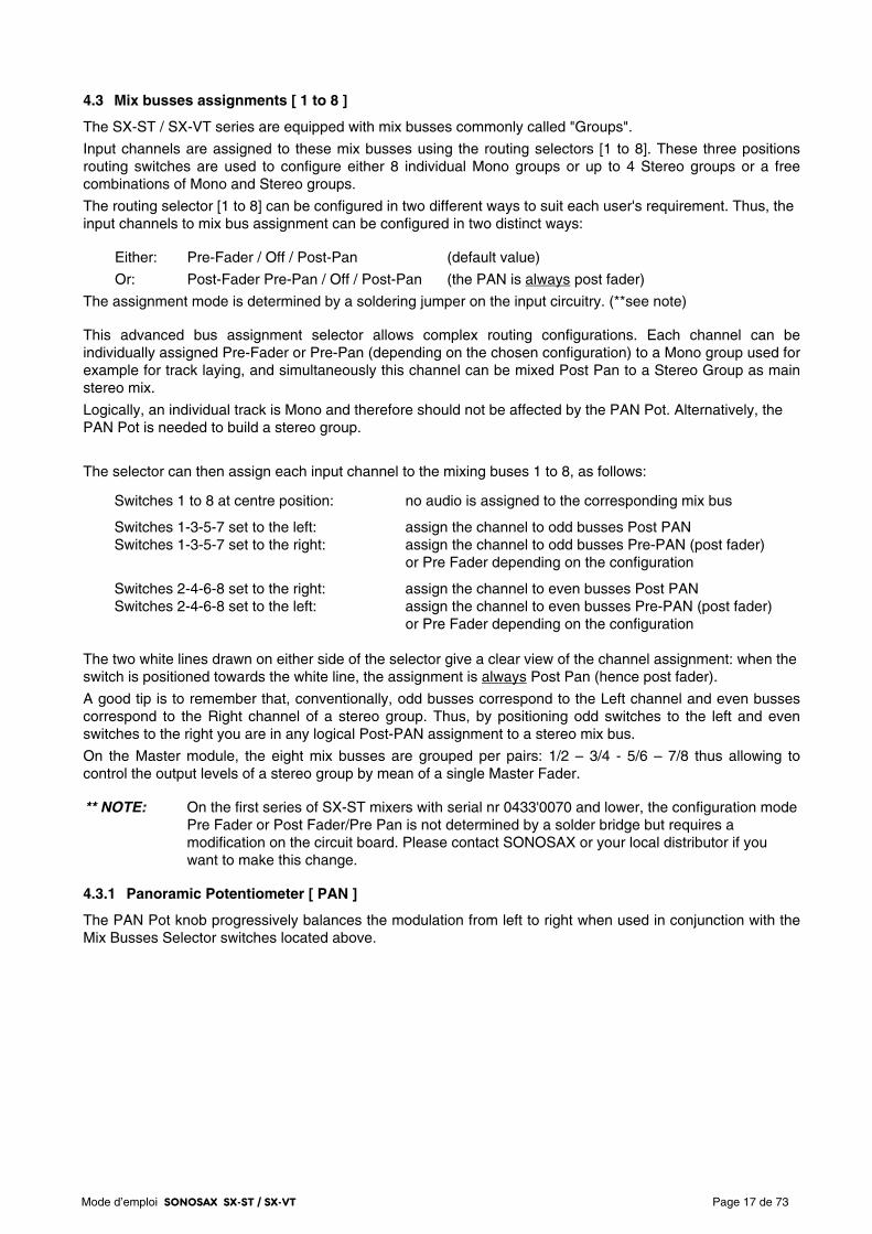
4.3 Mix busses assignments [ 1 to 8 ]
The SX-ST / SX-VT series are equipped with mix busses commonly called "Groups".
Input channels are assigned to these mix busses using the routing selectors [1 to 8]. These three positions routing switches are used to configure either 8 individual Mono groups or up to 4 Stereo groups or a free combinations of Mono and Stereo groups.
The routing selector [1 to 8] can be configured in two different ways to suit each user's requirement. Thus, the input channels to mix bus assignment can be configured in two distinct ways:
Either: Pre-Fader / Off / Post-Pan (default value)
Or: Post-Fader Pre-Pan / Off / Post-Pan (the PAN is always post fader)
The assignment mode is determined by a soldering jumper on the input circuitry. (**see note)
This advanced bus assignment selector allows complex routing configurations. Each channel can be individually assigned Pre-Fader or Pre-Pan (depending on the chosen configuration) to a Mono group used for example for track laying, and simultaneously this channel can be mixed Post Pan to a Stereo Group as main stereo mix.
Logically, an individual track is Mono and therefore should not be affected by the PAN Pot. Alternatively, the PAN Pot is needed to build a stereo group.
The selector can then assign each input channel to the mixing buses 1 to 8, as follows:
Switches 1 to 8 at centre position: no audio is assigned to the corresponding mix bus
Switches 1-3-5-7 set to the left: assign the channel to odd busses Post PAN Switches 1-3-5-7 set to the right: assign the channel to odd busses Pre-PAN (post fader) or Pre Fader depending on the configuration
Switches 2-4-6-8 set to the right: assign the channel to even busses Post PAN Switches 2-4-6-8 set to the left: assign the channel to even busses Pre-PAN (post fader) or Pre Fader depending on the configuration The two white lines drawn on either side of the selector give a clear view of the channel assignment: when the switch is positioned towards the white line, the assignment is always Post Pan (hence post fader).
A good tip is to remember that, conventionally, odd busses correspond to the Left channel and even busses correspond to the Right channel of a stereo group. Thus, by positioning odd switches to the left and even switches to the right you are in any logical Post-PAN assignment to a stereo mix bus.
On the Master module, the eight mix busses are grouped per pairs: 1/2 – 3/4 - 5/6 – 7/8 thus allowing to control the output levels of a stereo group by mean of a single Master Fader.
** NOTE: On the first series of SX-ST mixers with serial nr 0433'0070 and lower, the configuration mode Pre Fader or Post Fader/Pre Pan is not determined by a solder bridge but requires a modification on the circuit board. Please contact SONOSAX or your local distributor if you want to make this change.
4.3.1 Panoramic Potentiometer [ PAN ]
The PAN Pot knob progressively balances the modulation from left to right when used in conjunction with the Mix Busses Selector switches located above.
Mode d’emploi SONOSAX SX-ST / SX-VT Page 18 de 73
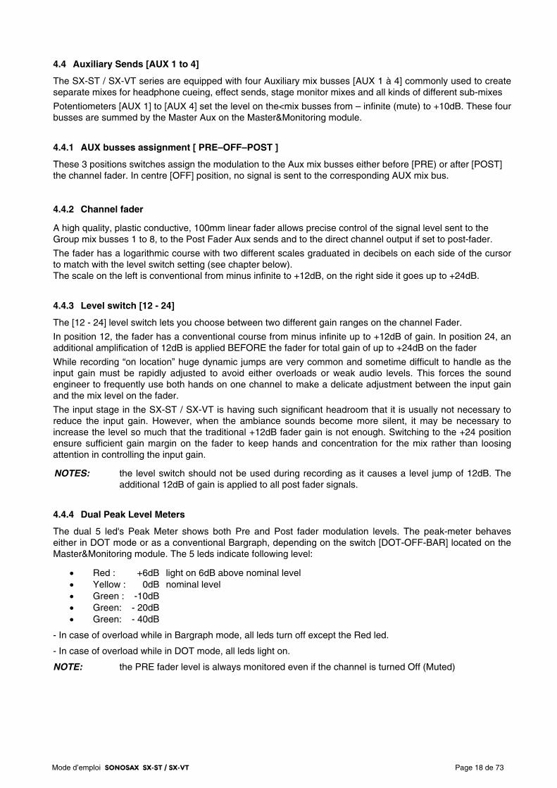
4.4 Auxiliary Sends [AUX 1 to 4]
The SX-ST / SX-VT series are equipped with four Auxiliary mix busses [AUX 1 à 4] commonly used to create separate mixes for headphone cueing, effect sends, stage monitor mixes and all kinds of different sub-mixes
Potentiometers [AUX 1] to [AUX 4] set the level on the<mix busses from – infinite (mute) to +10dB. These four busses are summed by the Master Aux on the Master&Monitoring module.
4.4.1 AUX busses assignment [ PRE–OFF–POST ]
These 3 positions switches assign the modulation to the Aux mix busses either before [PRE) or after [POST] the channel fader. In centre [OFF] position, no signal is sent to the corresponding AUX mix bus.
4.4.2 Channel fader
A high quality, plastic conductive, 100mm linear fader allows precise control of the signal level sent to the Group mix busses 1 to 8, to the Post Fader Aux sends and to the direct channel output if set to post-fader.
The fader has a logarithmic course with two different scales graduated in decibels on each side of the cursor to match with the level switch setting (see chapter below). The scale on the left is conventional from minus infinite to +12dB, on the right side it goes up to +24dB.
4.4.3 Level switch [12 - 24]
The [12 - 24] level switch lets you choose between two different gain ranges on the channel Fader.
In position 12, the fader has a conventional course from minus infinite up to +12dB of gain. In position 24, an additional amplification of 12dB is applied BEFORE the fader for total gain of up to +24dB on the fader
While recording “on location” huge dynamic jumps are very common and sometime difficult to handle as the input gain must be rapidly adjusted to avoid either overloads or weak audio levels. This forces the sound engineer to frequently use both hands on one channel to make a delicate adjustment between the input gain and the mix level on the fader.
The input stage in the SX-ST / SX-VT is having such significant headroom that it is usually not necessary to reduce the input gain. However, when the ambiance sounds become more silent, it may be necessary to increase the level so much that the traditional +12dB fader gain is not enough. Switching to the +24 position ensure sufficient gain margin on the fader to keep hands and concentration for the mix rather than loosing attention in controlling the input gain.
NOTES: the level switch should not be used during recording as it causes a level jump of 12dB. The additional 12dB of gain is applied to all post fader signals.
4.4.4 Dual Peak Level Meters
The dual 5 led's Peak Meter shows both Pre and Post fader modulation levels. The peak-meter behaves either in DOT mode or as a conventional Bargraph, depending on the switch [DOT-OFF-BAR] located on the Master&Monitoring module. The 5 leds indicate following level:
• Red : +6dB light on 6dB above nominal level • Yellow : 0dB nominal level • Green : -10dB • Green: - 20dB • Green: - 40dB
- In case of overload while in Bargraph mode, all leds turn off except the Red led.
- In case of overload while in DOT mode, all leds light on.
NOTE: the PRE fader level is always monitored even if the channel is turned Off (Muted)
Mode d’emploi SONOSAX SX-ST / SX-VT Page 19 de 73
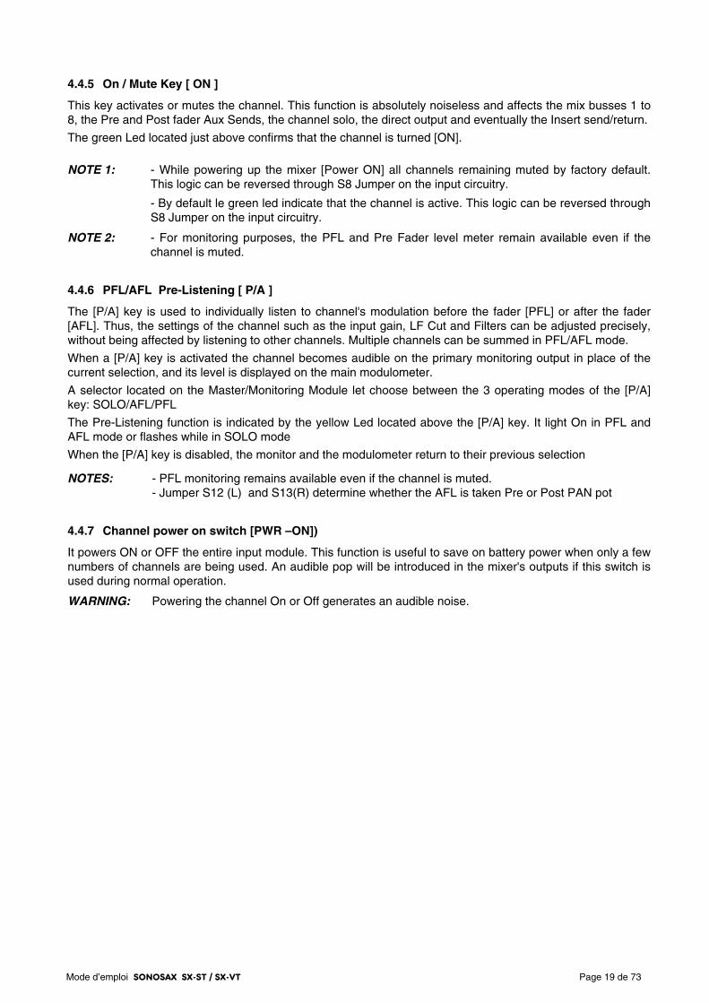
4.4.5 On / Mute Key [ ON ]
This key activates or mutes the channel. This function is absolutely noiseless and affects the mix busses 1 to 8, the Pre and Post fader Aux Sends, the channel solo, the direct output and eventually the Insert send/return.
The green Led located just above confirms that the channel is turned [ON].
NOTE 1: - While powering up the mixer [Power ON] all channels remaining muted by factory default.
This logic can be reversed through S8 Jumper on the input circuitry.
- By default le green led indicate that the channel is active. This logic can be reversed through S8 Jumper on the input circuitry.
NOTE 2: - For monitoring purposes, the PFL and Pre Fader level meter remain available even if the channel is muted.
4.4.6 PFL/AFL Pre-Listening [ P/A ]
The [P/A] key is used to individually listen to channel's modulation before the fader [PFL] or after the fader [AFL]. Thus, the settings of the channel such as the input gain, LF Cut and Filters can be adjusted precisely, without being affected by listening to other channels. Multiple channels can be summed in PFL/AFL mode.
When a [P/A] key is activated the channel becomes audible on the primary monitoring output in place of the current selection, and its level is displayed on the main modulometer.
A selector located on the Master/Monitoring Module let choose between the 3 operating modes of the [P/A] key: SOLO/AFL/PFL
The Pre-Listening function is indicated by the yellow Led located above the [P/A] key. It light On in PFL and AFL mode or flashes while in SOLO mode
When the [P/A] key is disabled, the monitor and the modulometer return to their previous selection
NOTES: - PFL monitoring remains available even if the channel is muted. - Jumper S12 (L) and S13(R) determine whether the AFL is taken Pre or Post PAN pot
4.4.7 Channel power on switch [PWR –ON])
It powers ON or OFF the entire input module. This function is useful to save on battery power when only a few numbers of channels are being used. An audible pop will be introduced in the mixer's outputs if this switch is used during normal operation.
WARNING: Powering the channel On or Off generates an audible noise.
Mode d’emploi SONOSAX SX-ST / SX-VT Page 20 de 73
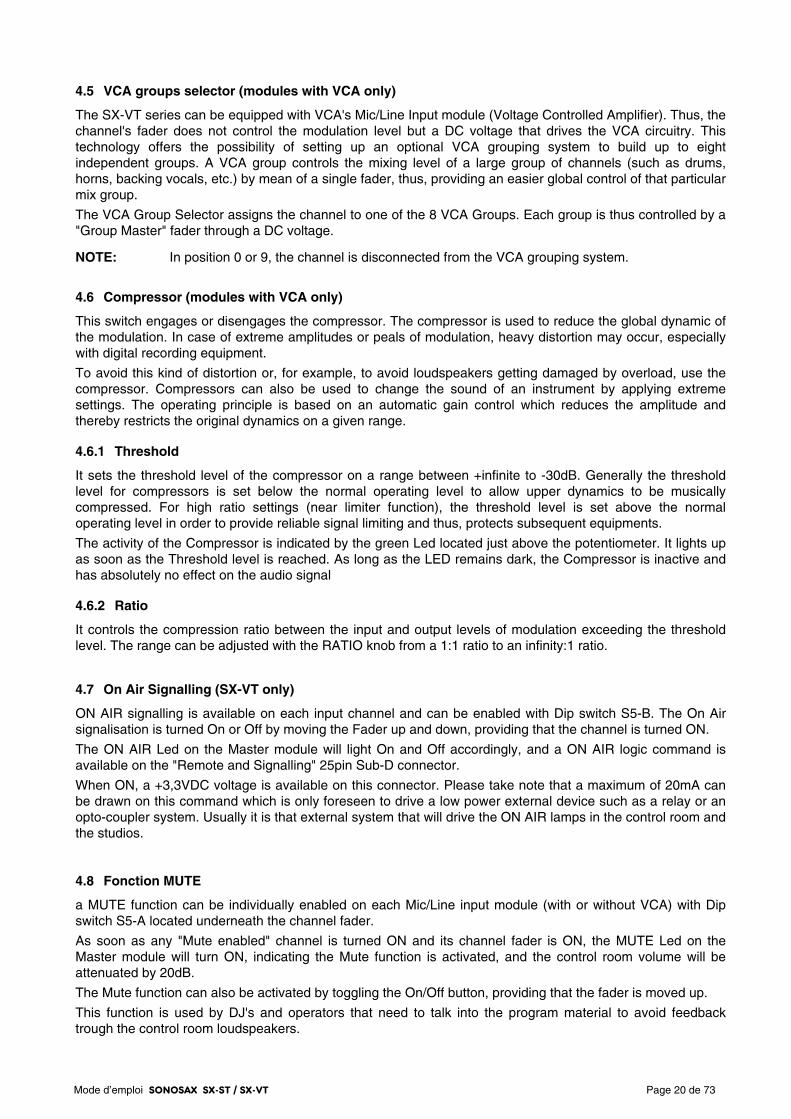
4.5 VCA groups selector (modules with VCA only)
The SX-VT series can be equipped with VCA's Mic/Line Input module (Voltage Controlled Amplifier). Thus, the channel's fader does not control the modulation level but a DC voltage that drives the VCA circuitry. This technology offers the possibility of setting up an optional VCA grouping system to build up to eight independent groups. A VCA group controls the mixing level of a large group of channels (such as drums, horns, backing vocals, etc.) by mean of a single fader, thus, providing an easier global control of that particular mix group.
The VCA Group Selector assigns the channel to one of the 8 VCA Groups. Each group is thus controlled by a "Group Master" fader through a DC voltage.
NOTE: In position 0 or 9, the channel is disconnected from the VCA grouping system.
4.6 Compressor (modules with VCA only)
This switch engages or disengages the compressor. The compressor is used to reduce the global dynamic of the modulation. In case of extreme amplitudes or peals of modulation, heavy distortion may occur, especially with digital recording equipment.
To avoid this kind of distortion or, for example, to avoid loudspeakers getting damaged by overload, use the compressor. Compressors can also be used to change the sound of an instrument by applying extreme settings. The operating principle is based on an automatic gain control which reduces the amplitude and thereby restricts the original dynamics on a given range.
4.6.1 Threshold
It sets the threshold level of the compressor on a range between +infinite to -30dB. Generally the threshold level for compressors is set below the normal operating level to allow upper dynamics to be musically compressed. For high ratio settings (near limiter function), the threshold level is set above the normal operating level in order to provide reliable signal limiting and thus, protects subsequent equipments.
The activity of the Compressor is indicated by the green Led located just above the potentiometer. It lights up as soon as the Threshold level is reached. As long as the LED remains dark, the Compressor is inactive and has absolutely no effect on the audio signal
4.6.2 Ratio
It controls the compression ratio between the input and output levels of modulation exceeding the threshold level. The range can be adjusted with the RATIO knob from a 1:1 ratio to an infinity:1 ratio.
4.7 On Air Signalling (SX-VT only)
ON AIR signalling is available on each input channel and can be enabled with Dip switch S5-B. The On Air signalisation is turned On or Off by moving the Fader up and down, providing that the channel is turned ON.
The ON AIR Led on the Master module will light On and Off accordingly, and a ON AIR logic command is available on the "Remote and Signalling" 25pin Sub-D connector.
When ON, a +3,3VDC voltage is available on this connector. Please take note that a maximum of 20mA can be drawn on this command which is only foreseen to drive a low power external device such as a relay or an opto-coupler system. Usually it is that external system that will drive the ON AIR lamps in the control room and the studios.
4.8 Fonction MUTE
a MUTE function can be individually enabled on each Mic/Line input module (with or without VCA) with Dip switch S5-A located underneath the channel fader.
As soon as any "Mute enabled" channel is turned ON and its channel fader is ON, the MUTE Led on the Master module will turn ON, indicating the Mute function is activated, and the control room volume will be attenuated by 20dB.
The Mute function can also be activated by toggling the On/Off button, providing that the fader is moved up.
This function is used by DJ's and operators that need to talk into the program material to avoid feedback trough the control room loudspeakers.
Mode d’emploi SONOSAX SX-ST / SX-VT Page 21 de 73
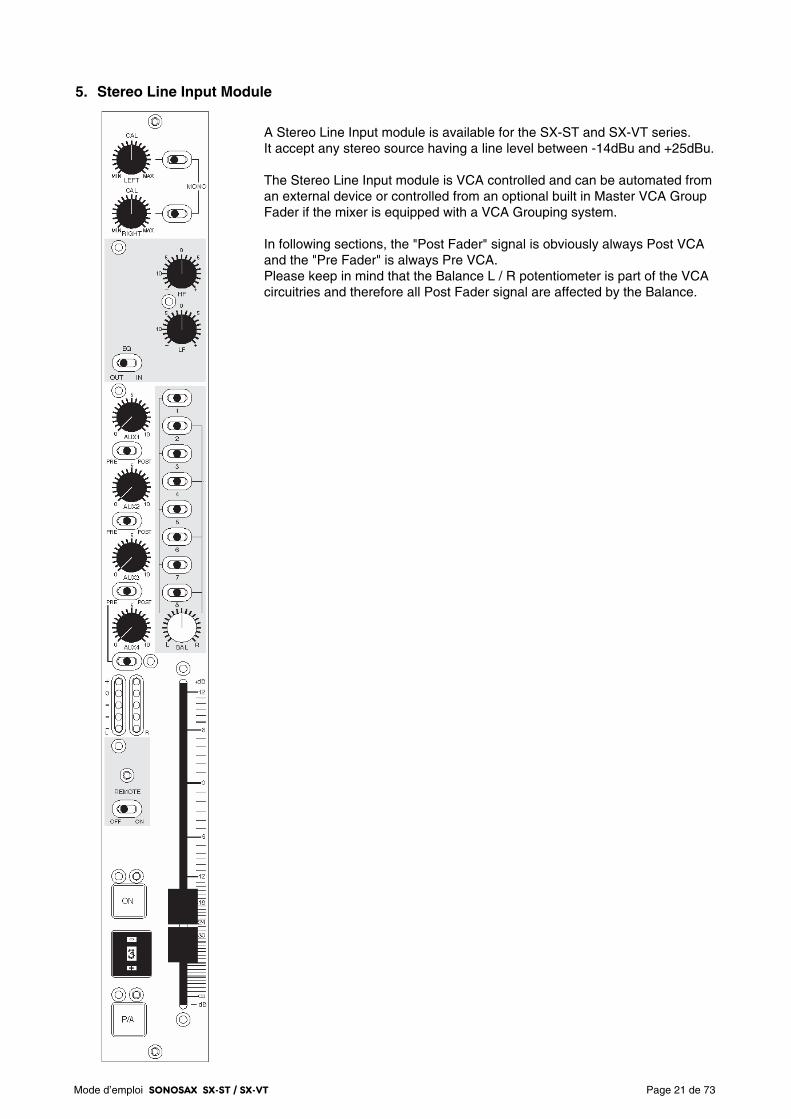
5. Stereo Line Input Module
A Stereo Line Input module is available for the SX-ST and SX-VT series. It accept any stereo source having a line level between -14dBu and +25dBu. The Stereo Line Input module is VCA controlled and can be automated from an external device or controlled from an optional built in Master VCA Group Fader if the mixer is equipped with a VCA Grouping system. In following sections, the "Post Fader" signal is obviously always Post VCA and the "Pre Fader" is always Pre VCA. Please keep in mind that the Balance L / R potentiometer is part of the VCA circuitries and therefore all Post Fader signal are affected by the Balance.
Mode d’emploi SONOSAX SX-ST / SX-VT Page 22 de 73
5.1 Left & Right gain controls
The potentiometers [LEFT] and [RIGHT] are used to individually adjust the input level of the Left and Right channels within a range of -20dB to +20dB from the central [CAL] position.
The central position [CAL] is a unity gain (0dB gain) and reflects the nominal input level.
5.2 Selector [ MONO ]
If both of the "Mono" selectors are switched toward their left position, the Left channel is routed to the Left or the Odd channel of a mix bus and the Right channel is routed to the Right or Even channel of a mix bus.
If the selector of the Left input channel is switched toward its right position, the Left input signal is routed to both the Left and Right mix busses.
If the selector of the Right input channel is switched toward its right position, the Right input signal is routed to both the Left and Right mix busses.
When both selectors are switched toward their right position, then the Left and the Right input signals are mixed into a Mono signal and routed to both the Left and Right mix busses.
5.3 Stereo Equalizer [ EQ ]
The Stereo input module provides with a 2 bands Equalizer for Trebles and Basses. The [IN – OUT] switch engages or bypasses the Equalizer. It is also used for instant comparison of filtered and non-filtered audio.
The HF controls a fixed shelving equalizer for treble adjustment. Shelving equalizers work on a very broad range of frequencies and, consequently, are very "musical". The upper harmonics are raised evenly, keeping their original musical relationship to each other.
8 kHz / 4dB per octave / ±12 dB at 8 kHz / ±15 dB at 16 kHz
The LF controls a fixed shelving equalizer for bass adjustment. A low frequency shelving equalizer will add or remove bass in a smooth, musical fashion.
80 Hz / 4dB per octave / ±12 dB at 80Hz / ±15 dB at 40Hz
5.4 Auxiliary Sends [AUX 1] to [AUX 4]
The SX-ST/SX-VT mixers provide with 4 Auxiliary Sends mix busses. [AUX 1] to [AUX 4] are used to create sub-mixes for headphone cueing, effect sends, stage monitor mixes and all kinds of different sub-mixes.
When turned fully clockwise, an additional 10dB gain is added to the Aux send bus
Potentiometers [AUX 1] to [AUX 4] set the level on the mix busses from – infinite (mute) to +10dB. These four busses are summed by the Master Aux on the Master&Monitoring module.
5.4.1 Auxiliary routing switches [PRE-OFF-POST]
A 3 positions switch [Pre-Off-Post] assigns the channels to the Aux busses before [PRE] or after [POST] the channel fader. In its centre [OFF] position, no signal is sent to the corresponding AUX bus.
In this Stereo Module, the AUX sends are paired, therefore the Left channel is sent to the odd AUX 1 & 3 while the Right channel is sent to even AUX 2 & 4.
NOTES: - AUX sends are sourced after the [MONO] selector, therefore the Left and/or Right channel may already have been routed to either of L or R channel or already being summed in MONO. - If AUX sends are selected Post Fader, the pair 1/2 and 3/4 are also affected by the Balance potentiometer.
Mode d’emploi SONOSAX SX-ST / SX-VT Page 23 de 73
5.5 Dual Peak level meter
The 5 Led's dual Peak Level meters show the levels of the Left and Right channel. The peak-meter behaves either in DOT mode or as a conventional Bargraph, depending on the switch [DOT-OFF-BAR] located on the Master&Monitoring module. The 5 leds indicate following level:
• Red : +6dB light on 6dB above nominal level • Yellow : 0dB nominal level • Green : -10dB • Green: - 20dB • Green: - 40dB
- In case of overload while in Bargraph mode, all leds turn off except the Red led.
- In case of overload while in DOT mode, all leds light on.
NOTES: The jumpers S13 and S14 determine whether the Meters show the signal Pre or Post-fader. In Pre-fader mode, the level will always be viewed even if the channel is off (Muted).
5.6 Assignment to mix busses 1/2 to 7/8
The stereo channels can be assigned to any pair of the mix busses by mean of the eight switches to create up to 4 stereo groups by using pairs 1/2 - 3/4 - 5/6 or 7/8.
Logically, if a stereo signal has been summed to Mono using the [MONO] switches at the input of the channel, this Mono signal can be assigned to any of the 8 Bus mixing.
The 3 position's routing switches assign the stereo signal to the mix busses either Pre Fader or Post Balance (Post Balance being obviously post fader!):
Switches 1 to 8 at centre position: no audio is assigned to the corresponding mix bus
Switches 1-3-5-7 set to the left: assign the left channel to odd busses Post Balance Switches 1-3-5-7 set to the right: assign the left channel to odd busses Pre Fader
Switches 2-4-6-8 set to the right: assign the right channel to even busses Post Balance Switches 2-4-6-8 set to the left: assign the right channel to even busses Pre Fader The two lines drawn on either side of the selector provides a clear view of the Pre Fader or Post-Balance assignment: when the switch is positioned to the line, the assignment is Post-Balance.
A good tip is to remember that, conventionally, Odd busses are defined as Left channels and Even buses are defined as Right channel in a stereo group. Therefore, by setting Odd switches to the Left and Even switches to the Right you logically assign the stereo channel Post Balance to the busses.
5.6.1 Channel Fader
The Stereo Input module is equipped with two VCA circuitries (Voltage Controlled Amplifier), one for each of the L & R channel. The fader controls the L & R audio levels in a range from – infinite to +12dB by means of a single DC voltage equally applied to both VCA's.
5.6.2 Left – Right Balance [ BAL ]
The Balance potentiometer is part of the VCA circuitries. It balances the stereo signal between the odd (Left) and the even (Right) sides of a mix bus pair by mean of a DC voltage applied in an opposite way to the VCA's
NOTE: the Balance also affects the AUX pairs 1/2 & 3/4 when selected Post Fader.
Mode d’emploi SONOSAX SX-ST / SX-VT Page 24 de 73
5.6.3 On / Mute Key [ ON ]
This key activates or mutes the channel. This function is absolutely noiseless and affects the mix busses 1 to 8, the Pre and Post fader Aux Sends, and the "SOLO" monitoring of the channels.
The green Led located just above the key lights on as soon as the channel is turned [ON]
NOTES: - While powering up the mixer [Power ON] all channels remaining muted by factory default. This logic can be reversed through S10 Jumper on the input circuitry. - For monitoring purposes, the PFL signal and Pre Fader level meter remain active even if the channel is turned OFF (Muted). - This ON/OFF function can be controlled from an external device. (optional on SX-VT only)
5.7 Fader Start [ REMOTE ]
This switch enables the "Fader Start" command from the Stereo module. The function allows to remotely Start/Stop any device supporting a "Fader Start" command.
The command is driven either by opening / closing the Fader, or by activating / deactivating the module through the [ON] key. The [Remote] Led indicates the status:
- the "STOP" command is activated as soon as the fader is closed and/or by muting the channels. The yellow Led is flashing.
- the "PLAY" command is activated as soon as the Fader is opened, even slightly, and the channel turned ON. The yellow Led is lighting steadily.
The Remote logic circuitries actuate two relays for the Start ( K3 ) and Stop ( K1 ) function. Thus the logic circuitries are totally isolated from external devices for optimal protection.
In normal mode, a Start and a Stop pulse of 125ms is sent to the corresponding relay every time the Start/Stop status changes over.
This command can be changed from "Pulse" mode to "State" by changing the internal Dip switch S9-A to "On" (or 1). If State mode is chosen, then only the "Stop" relay is activated as follow:
- STOP Mode: the relay contact is open
- PLAY Mode: the relay contact is closed.
5.8 PFL/AFL Pre-Listening [ P/A ]
The P/A push button is used to monitor the channel signal Pre-Fader (PFL) or After-Fader (AFL) and to check its level on the main level meters. A selector located on the Master&Monitoring Module let choose between the 3 operating modes of the [P/A] button: SOLO/AFL/PFL.
This Pre-Listening function is indicated by the yellow Led located above the [P/A] key. It lights On in PFL and AFL mode or flashes while in SOLO mode
NOTES: - The PFL monitoring remains active even if the channel is turned OFF (Muted). - AFL being taken post VCA, the signal is then obviously post Balance.
5.9 VCA groups selector (optional on SX-VT Series only)
The VCA group selector works the same way as on the Mic/Line input with VCA. Please refer to this section for further detailed information's.
Mode d’emploi SONOSAX SX-ST / SX-VT Page 25 de 73
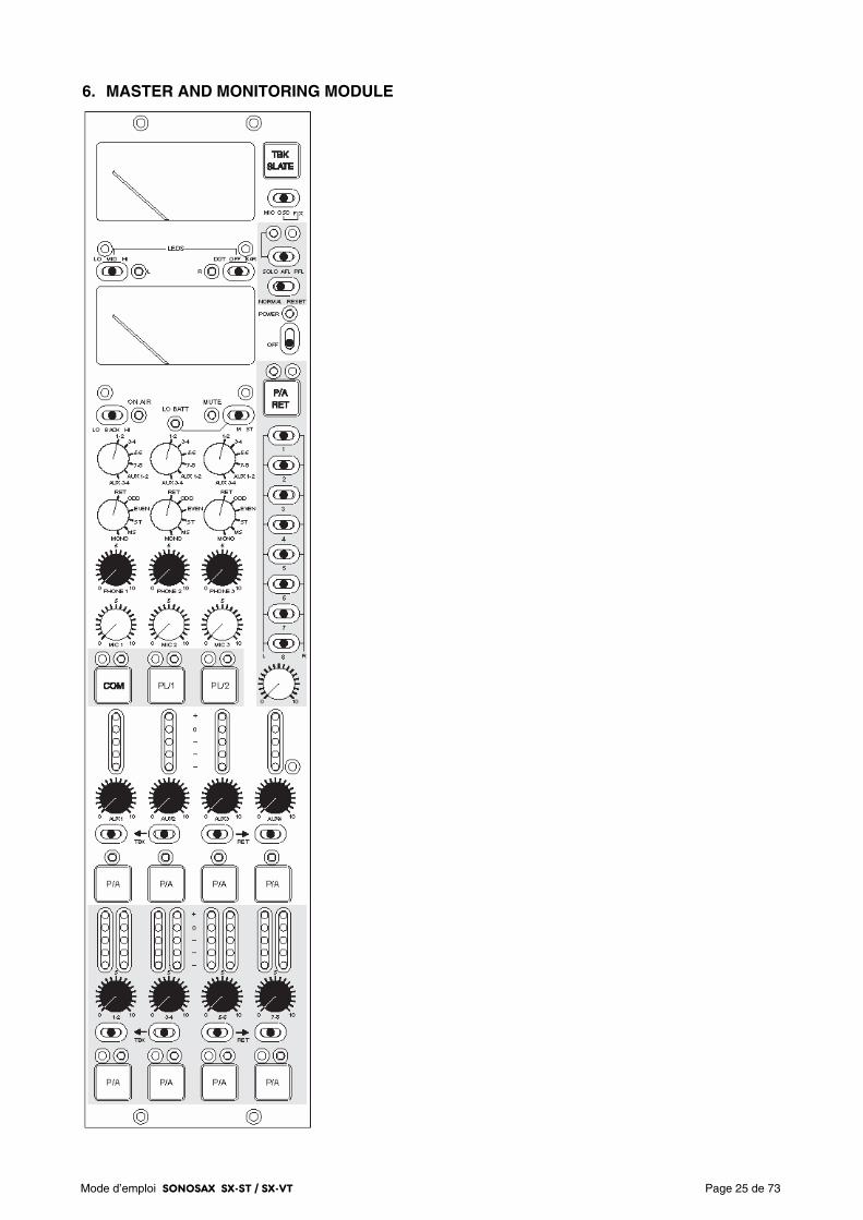
6. MASTER AND MONITORING MODULE
Mode d’emploi SONOSAX SX-ST / SX-VT Page 26 de 73
6.1.1 METERING
Two high precision moving coil Peak Meters read the modulation level of the source selected on the Main Monitor rotary switch, offering a wide scale of 44dB, ranging from –32dB up to +12dB.
The upper meter shows the Left channel or the phase correlation,
The lower meter shows the Right channel or the battery level.
When any [P/A] button is depressed, the meters show the corresponding AFL/PFL signal.
6.1.2 Meter's operating mode [ ST-M-Low Batt ]
This 3 positions switch selects the operating mode of the moving coil Meters.
ST (Stereo): the meters display on a conventional way the Left and Right audio
M (Mono): the upper meter shows the phase correlation of the selected source to easily detect a phase correlation error and to verify the mono compatibility. The lower meter shows the highest modulation level of either the L or the R channel. The two red Leds between the meters indicate which one of the Left or the Right peak signal is being displayed.
Low Batt: Press the switch to its momentary left most position to check the battery level. The lower meter will then indicate the average voltage per cell.
6.1.3 Meter's backlight [ BACK ]
The backlight of the two moving coil meters is set by this switch
OFF position: Backlights are turned OFF. MID position: Medium backlight intensity (dimmed). HI position: Maximum backlight intensity.
6.1.4 Led's operating mode [ LEDS ]
Two switches between the Meters set the operating mode and the lighting intensity of all Leds and Bargraph meters on the mixing console.
The switch on the left sets the Led's intensity:
LO position: Minimum Led’s light intensity. MID position: Medium Led’s light intensity. HI position: Maximum Led’s light intensity.
The switch on the right sets the operating mode of the meters:
DOT position: only one Led - corresponding of the highest peak level - is lighting OFF position: all meters are turned OFF. BAR position: peak meters operate as Bargraph
6.1.5 Signalling Leds [ ON AIR ] and [ MUTE ] (SX-VT only)
"On Air" and monitoring "Mute" signalling are two functions typically used in Broadcast and Live applications. These functionalities can be activated trough dip switches located under the channel fader on each input module.
When a channel is turned ON, the On Air and/or the Mute functions will be activated as soon as the channel Fader's is opened. The [On Air] and [Mute] signalling Leds will light On accordingly.
For detailed information's, please refer to the corresponding section in the Input modules chapters.
Mode d’emploi SONOSAX SX-ST / SX-VT Page 27 de 73
6.2 Talkback/SLATE and Oscillator
The SX-ST/SX-VT mixers feature advanced "Talkback" and "Slate" functionalities. Pressing the [TBK/SLATE] key located on the upper right corner on the Master & Monitoring module will send either the modulation of an external communication microphone or the internally generated 1kHz sine tone to a bus named "TalkBack".
This "TalkBack" bus can be fed directly into the Groups and Aux mix busses through the [← TBK - RET →] switches located underneath the corresponding Mains and Auxiliaries Master Faders. (See chapter 6.8.6)
NOTE: the Talkback/Slate bus is totally independent of the Communication and Private Line circuitries; although they use the same microphone connected to the 5 pin Binder connector.
6.2.1 Source Selector [ MIC-OSC-FIX ]
This three positions switch selects which of the two possible sources (external Microphone or Generator) is assigned to the "Talkback" bus:
MIC position: the external communication microphone is momentary sent to the Talkback bus when the [TBK/Slate] key is depressed
OSC position: the internal oscillator generates a 1 kHz sine wave tone which is momentary sent to talkback bus when the [TBK/Slate] key is depressed
FIX position: the 1 kHz sine wave tone is permanently sent to the talkback bus. (for calibration or test procedures).
6.3 Pre listening Selector [ PFL-AFL-SOLO ]
These are new features developed for SONOSAX SX-ST/SX-VT series to allow users to configure the operating mode of the pre listening command keys [P/A] available on each input channels, on the Groups masters and on the Auxiliary masters.
PFL Position: [P/A] keys are configured for PFL operating mode (Pre Fader Listening)
AFL Position: [P/A] keys are configured for AFL operating mode (After Fader Listening)
SOLO Position: [P/A] keys are configured for "SOLO" operating mode as exclusive "SOLO In Place". This mode concerns only the [P/A] key of the input modules and has no effect on [P/A] keys of the Group masters or Aux master. Solo is used to "isolate" one (or more) input channel "In Lieu & Place" of any others in a mix by automatically muting all other input channels! In this mode, the red Led above the switch and the yellow Led of the corresponding [P/A] key are flashing to warn users that the SOLO function is activated.
6.3.1 P/A operating mode [ Normal-Reset ]
This switch determines the operating mode of the [P/A] keys:
NORMAL: This mode is additive, so one or more [P/A] buttons can be individually activated or released.
RESET: This mode is exclusive. Pressing a [P/A] key will activate the corresponding channel and will automatically release any previously activated key (mutual reset) which allows to quickly switching from one channel to another.
6.4 Powering ON/OFF
Turns On and Off the internal DC/DC converter that powers the entire mixer. Please refer to Chapter 3 for further information's concerning the powering of the console.
Mode d’emploi SONOSAX SX-ST / SX-VT Page 28 de 73
6.5 Return lines 1 to 8 [ RETURN ]
Up to 8 return lines can be connected to the 25 pin Sub-D receptacle [RETURN 1-8]. They can be used to monitor of a multi-track recorder as example or the feed any external line directly into any main mix bus.
Each return line can be individually assigned and mixed onto a stereo "Return Mix Bus" through the 8 return switches:
Left position: assign the line to the left channel of the stereo Return Mix Bus
Middle OFF position: the return is not assigned
Right position: assign the line to the right channel of the stereo Return Mix Bus
This stereo "Return Mix Bus" can be fed directly into the main Group mix busses or in the Aux mix busses trough the [← TBK - RET →] switches located underneath the corresponding Master faders.
6.5.1 Return's Master Level
The potentiometer under the switches adjusts the level of the Return Mix bus between –infinite and +10dB.
NOTE: On request the input circuitry can be modified to add 10dB of gain, thus compensating the output level of some equipment not providing with a true line level.
6.5.2 Return's Pre-Listening [ P/A RET ]
The [P/A RET] key is used to monitor the return lines Pre (PFL) or Post (AFL) Fader depending of the P/A operating mode selector. It behaves the same way as the pre listening function of the input channel.
NOTE: On request this key can be locked for AFL mode only, thus making this key independent of the [AFL-PFL-SOLO] selector.
6.6 MONITORING
The SONOSAX SX-ST and SX-VT provide with three independent monitoring sections.
The left most Monitor section (the Main Monitor) is dedicated to the sound engineer working on the mixer. The main peak-meters are directly linked to this main monitoring. When any [P/A] key is depressed, the main monitor and the peak-meters switch over from the selected monitor source to the selected P/A function.
The two additional middle and right most monitoring sections are used for independent remote monitoring, both providing with an individual communication system (Private Lines). These are commonly used to return different monitoring selections to e.g. the boom operator and the director/producer while on location recording, or to a speaker cabin and to the video control room in broadcasting applications such as an OB Van.
6.6.1 Monitor Source Selector
The upper three rotary switches select the source to be monitored:
1-2 to 7-8 : select Master Groups per pair 1 (Left) – 2 (Right) / 3 (Left) – 4 (Right) etc AUX 1-2 : select Aux Sends 1 (Left) and 2 (Right) AUX 3-4 : select Aux Sends 3 (Left) and 2 (Right)
6.6.2 Monitor Mode selector
The lower three rotary switches define the listening mode of the selected source:
RET : monitors the after fader stereo mix of the 8 Return tracks ODD : the odd channel only of the selected stereo source is monitored in Mono EVEN : the even channel only of the selected stereo source is monitored in Mono ST : the selected source is monitored in stereo M : the selected stereo source is summed in Mono to easily check the Mono compatibility
and to detect phase errors MS: decode a MS signal for monitoring purposes only.
The M/S decoder is for monitoring purpose only and does not affect the main outputs. The M-(left) channel is applied to both L & R channels in phase and the S-(right) channel is applied in phase to the left channel and out of phase to the right channel. The M/S decoder has a fixed ratio of 50%
NOTE: in Odd, Even and Mono modes, the modulation is heard in mono on both left and right sides of the monitor output.
Mode d’emploi SONOSAX SX-ST / SX-VT Page 29 de 73
6.6.3 Headphone volume [ PHONE 1 ] to [ PHONE 3 ]
Set the headphone volume of the corresponding monitor output (1 to 3) from - infinite (Mute) to +15 dBu.
The headphone output of the main monitoring is available both on the ¼" jack and on the 5 pin Binder connector on the rear of the mixer.
The outputs of monitoring sections 2 & 3 are both available on the 15 pin Sub-D connector [MON/PL1-2]. Different split adapter's 15pin Sub-D to female jack or XLR are available. Pease ask you local distributor.
WARNING: The headphone amplifiers are quite powerful. It is highly recommended to set the headphone level at a reasonable level to protect our precious ears
6.7 Communication and Private Lines [ COM – PL1 – PL2 ]
The SX-ST / SX-VT mixing consoles offer three independent communication systems: a main [COM] for general purposes and two full duplex Private Lines [PL1] and [PL2] used for communication within the second and third monitoring sections.
COM : communication sends only (no return) to all lines including PL1 and PL2
PL1 : full duplex private communication through the second monitor section
PL2 : full duplex private communication through the third monitor section
The COM and Talkback/Slate use the same external microphone. An external electrets or a condenser microphone must be connected to the [COM] 5pin binder connector.
NOTE: The internal switch S3 selects the mic powering voltage: 48V phantom for condenser microphones or 6VDC for electrets microphones.
For PL1 and PL2 communication's returns, two microphone inputs are available on the 15pinSub-D connector [MON/PL1-2]. (See addendum for wiring diagram).
NOTE: PL1 and PL2 microphone inputs permanently provide with 48V phantom.
6.7.1 Comm. Monitor Attenuation
When activating any of the communication line - COM / Slate / PL1 or PL2 - the program listened at the monitor outputs can be either dimmed by approx 20dB or stay at its nominal level. Some users prefer to dim the monitoring level for a clear duplex communication; others prefer to keep a permanent control on the monitored program by mixing the duplex communication to the program that remains at nominal level.
Internal jumpers define individually for each monitor section if the monitor program is dimmed or not.
6.7.2 [ Mic 1 ] to [ Mic 3 ]
These three potentiometers adjust the "send" level of the slate and communication microphones over a range from –infinite to +10dB:
[MIC 1] : adjust the level of the "COM & TBK/Slate" microphone
[MIC 2] : adjust the level of the return communication's microphone PL1
[MIC 3] : adjust the level of the return communication's microphone PL2
NOTE: the gain of the mic. Preamplifiers are internally adjustable trough a Trim.
6.7.3 Side Tone
In a duplex communication system, the "Side Tone" is the level at which one is hearing his own voice during the communication. Internal trimmers allow adjusting these levels independently for each of the COM –PL1 and PL2 sections.
Mode d’emploi SONOSAX SX-ST / SX-VT Page 30 de 73
6.8 MASTER SECTION
6.8.1 GROUP Masters
The summing amplifiers are mixing the modulation assigned on the input channels to the 8 mix busses. The output level of the Groups is controlled per pairs: 1-2 / 3-4 / 5-6 / 7-8. The rotary stereo master faders adjust the output level from -infinity (mute) to 0dB (unity gain).
The nominal output level is set either at +6dBu or at +4dBu (please specify when ordering). It corresponds to a reading of "0 dB" on the main modulometer and on the 5 leds peak-meters.
The sums of the 8 Groups are then sent to the main outputs on the 25 pin Sub-D connector [OUTPUT1 to 8]. Depending on the rear panel configuration, the XLR3-M receptacle [OUT1] to [OUT4] corresponding to the first four Groups are wired in parallel to this multi pin connector. The configuration of the rear panel must be specified at the order.
The outputs of the Group masters are electronically balanced, transformer less.
The wiring of XLR-3 male receptacles for OUT 1 to OUT4 is:
Pin1 = Gnd / Pin2 = High (+) / Pin3 = Low (-).
Please refer to the addendum for the wiring diagram of the 25 pin Sub-D connector
To connect the main output on an unbalanced receiver's input, pin 1 & 3 must be bridged and connected to the Gnd of the receiver's input. The pin 2 is to be used as an unbalanced line output.
WARNING: Meanwhile the outputs are protected against DC voltages, we strongly recommend not to connect a phantom power to the output of the mixer (for example when connecting to a camera input, make sure that the phantom power of the camera is turned off).
6.8.2 AUX Masters
The Auxiliary master's work similarly to the Group masters. The output level of the Auxiliaries is individually controlled. The four rotary master faders AUX1 to AUX4 adjust the output level from -infinity (mute) to 0dB (unity gain).
The nominal output level is set either at +6dBu or at +4dBu (please specify when ordering). It corresponds to a reading of "0 dB" on the peak-meters.
The sums of the 4 Auxiliaries are then sent to the main outputs on the 15 pin Sub-D connector [AUX 1-4/VU]. The first four Groups are wired in parallel to the XLR3-M receptacle [OUT1] to [OUT4]. Depending on the rear panel configuration the Aux3 and Aux4 are replaced by XLR3-F connector to connect of the return lines Return1 and Return 2 (please specify when ordering)
The outputs of the Auxiliary masters are electronically balanced, transformer less.
The wiring of XLR-3 male receptacles for OUT 1 to OUT4 is:
Pin1 = Gnd / Pin2 = High (+) / Pin3 = Low (-).
Please refer to the addendum for the wiring diagram of the 15 pin Sub-D connector
6.8.3 Modulomètre à 5 Leds
The dual 5 led's Peak Meter indicate the Post fader modulation levels. The peak-meter behaves either in DOT mode or as a conventional Bargraph, depending on the switch [DOT-OFF-BAR] located on the Master&Monitoring module. The 5 leds indicate following level:
• Red : +6dB light on 6dB above nominal level • Yellow : 0dB nominal level • Green : -10dB • Green: - 20dB • Green: - 40dB
- In case of overload while in Bargraph mode, all leds turn off except the Red led.
- In case of overload while in DOT mode, all leds light on. .
Mode d’emploi SONOSAX SX-ST / SX-VT Page 31 de 73
6.8.4 Key [ P/A ]
The P/A key on the Groups and Auxiliary master sections are used to monitor the corresponding mix busses Pre- (PFL) or Post- (AFL) Fader, depending of the PFL/AFL mode selector.
This Pre-Listening function is indicated by the yellow Led located above the [P/A] key
NOTE: - The Main Groups are monitored in stereo; the Auxiliaries are monitored in mono. - The [SOLO] function obviously does not apply to the P/A monitoring of the master section.
6.8.5 Commutateurs [ Talkback-Off-Return ]
These three states switches under the Groups and Auxiliaries master faders assign and mix either the "Talkback/Slate" bus or the stereo "Return bus" to the corresponding pair of Groups and Auxiliary busses:
Left ← TBK position: assign the talkback/Slate bus to the Group and/or the Aux mix busses
Middle OFF position: No assignment to mix bus.
Right → RET position: assign the Return bus to the Group and/or the Aux mix busses
NOTE: - The Return bus is assigned in stereo to the Groups; the left channel is assigned to the odd
Groups and the right channel is assigned to the even busses The Return bus is assigned in mono to the Auxiliaries; the left channel is assigned to the Auxes 1 and 3 Groups and the right channel is assigned to the Auxes 2 and 4.
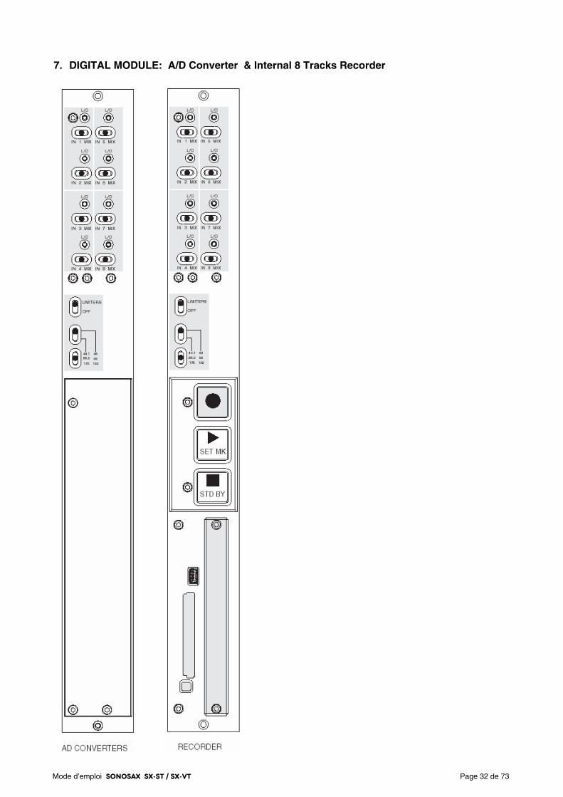
Mode d’emploi SONOSAX SX-ST / SX-VT Page 32 de 73
7. DIGITAL MODULE: A/D Converter & Internal 8 Tracks Recorder
Mode d’emploi SONOSAX SX-ST / SX-VT Page 33 de 73
7.1 A/D Converter
The 8 ways high quality Analogue to Digital converter is located on the upper half of the Digital module. It has a resolution of 24 bits and provides with sampling frequencies ranging from 44,1kHz up to 192 kHz. Its overall dynamic range reaches 120dB.
Each channel is equipped with a Limiter to protect the converter against eventual "clipping".
The 8 digital channels – 4x AES/EBU pairs – are available on the 25 pin Sub-D connector [DIGITAL I/O] on the rear panel of the mixing console. These 4 four digital outputs are transformer balanced and comply with the AES31 standard. The configuration of these digital outputs is:
AES 1 = channels 1 & 2 AES 2 = channels 3 & 4
AES 3 = channels 5 & 6 AES 4 = channels 7 & 8
Please refer to the addendum for the wiring diagram of the 25 pin Sub-D connector.
7.1.1 Sourcing selector [IN 1 MIX] to [IN 8 MIX]
The eight A/D Converters receive either the direct output of the first 8 input channels or the 8 master outputs of the Groups 1 to 8. The switches [IN 1 MIX] to [IN 8 MIX] individually select for each digital channel which of the sources is sent to the corresponding A/D converter:
- Position [IN]: the direct output of the corresponding INput module is sent to the A/D Converter. It is the same modulation as outputted at the [LINE OUT 1-8] connector and thus it depends on the internal selection Pre EQ – Post EQ – Post Fader.
- Position [MIX]: the modulation of the corresponding Group is sent of the A/D Converter.
- Centre Position: The A/D Converter is powered off, thus reducing the overall power consumption of the console. The A/D Converter always works per pair; therefore both switches of the same pair must be in centre position to power off the converter. Please note that powering the ADC on or off generate an audible noise.
7.1.2 Red led indicator [ L/O ]
The red Led [L/O] located above each source selector lights on either to indicate the Limiter activity [L] (when the modulation reaches the Threshold of the limiter) or when the modulation reaches the clipping level at 0dBFS [O] (O= overflow).
NOTE: as soon as one of the channel of an ADC reaches the clipping level, both leds will light On to indicate the Overflow
7.1.3 Protection Limiter's [ LIMITERS ]
Each of the eight channels of the digital module is equipped with an individual limiter to prevent the ADCs from eventual clipping (or overflow). To provide with an efficient protection, the Limiters have a very fast attack time of half a period.
The [LIMITERS] switch engages or disengages the eight limiters simultaneously.
The Limiter's Threshold is factory set at -3dBFS; its "compression" ratio is approx 15:1
7.1.4 Sampling frequencies
The A/D Converters have a fixed resolution of 24bits; the sampling frequencies stage from 44,1 up to 192kHz, and is determined by two switches:
- The upper switch selects one of the two fundamentals frequencies; 44,1KHz or 48KHz
- The lower switch selects a multiple of these fundamentals: 44,1 – 88,2 – 176kHz or 48 – 96 – 192kHz
NOTE: The 0.1% Pull Up / Pull Down functionality, commonly used in NTSC domain, is only possible if the internal recorder is installed.
Mode d’emploi SONOSAX SX-ST / SX-VT Page 34 de 73
7.1.5 Clocking and Sync
The A/D Converters are synchronized by an internal clock having an accuracy of ± 2ppm. When the Digital module is installed, the same clock is used to synchronize the internal DC/DC converter powering the entire mixer, thus avoiding phasing problem or digital noises.
Synchronizing the ADC trough an external clock – such as a video clock or a wordclock – is possible only when the Internal Recorder is installed. If the Digital module holds the A/D converter only - without Recorder – the A/D Converter will only lock on its internal clock; thus the ADC will be working as "Master".
A wordclock output is available on the Lemo 5 pin connector to synchronize external equipments such as an external recorder.
The mating cable connector is a Lemo 5pin SONOSAX Reference nr: SX860232 Lemo Reference nr: FGG.0B.305.CLAG52
Pin 1 = GND / Pin 2 = T.C. IN / Pin 3 = n.c. / Pin 4 = WordClock Out / Pin 5 = T.C. OUT
Mode d’emploi SONOSAX SX-ST / SX-VT Page 35 de 73
8. INTERNAL RECORDER
The internal 8 tracks recorder occupies the lower half of the digital module. It includes a keypad with three push buttons, a compartment for the hard disk, a slot for removable CF card, a USB 2.0 port and a wired remote control.
The recorder works in conjunction with the 8 channels A/D converter located just above. It can record up to 8 tracks on the hard disk - or on a SSD drive as an option - and up to two independent tracks on the CompactFlash card. The CF card can also operate in Mirroring mode, so that it records simultaneously the exact copy of what is recorded on the hard disk.
The WAV files are PCM encoded in 24 or 16 bit and contain a double implementation of BWF and iXML meta data's.
NOTE: To avoid loss of files during recording, the recorder continuously monitors the [Power Off] switch of the console. It prevents turning off the console if a recording is in progress or as long as the recorder still "writing" on the hard disk.
8.1 CONNECTIONS
A USB port is available on the front panel for files transfer to a computer and a set of connectors on the rear panel provides connections for the remote control, clock synchronization and time code.
8.1.1 Port USB 2.0
This connector on the front panel is a USB 2.0 only and is not compatible with older USB 1.0 standard.
It allows connection to any computer having a USB 2.0 port (PC or MAC). Once it is connected to a computer, the hard drive and / or card the ComapctFash appear on the desktop as an external media.
WARNING: when connecting to a computer, it is imperative to use a certified cable "USB 2 High Speed". The speed of data transmission is such that the use of cable not certified "High Speed" may cause malfunctions (disk not recognized or not appearing on the desktop - Windows error Code 10, etc.)
8.1.2 Remote Connector [ REMOTE ]
This connector is used only for connecting the dedicated remote and can not be used for other purposes. The wired remote is included with the recorder. It is used to configure all the parameters of the recorder and to display the modulation levels of the 8 tracks of hard disk.
IMPORTANT: The remote control must always be connected before powering up the console to initialize the internal recorder. If the remote is not connected before powering up the recorder will not be initialized, however the A/D converter module will remain available.
8.1.3 Time Code Connector [ TC ]
This 5 pin Lemo connector can either receive an external Time Code, or to provide a time code output in all common formats, including the y-23.976. This connector also provides with the WordClock Out of the A/D converter. The pin out matches with the Aaton standard
The mating cable connector is a Lemo 5pin SONOSAX Reference nr: SX860232 Lemo Reference nr: FGG.0B.305.CLAG52
Pin 1 = GND / Pin 2 = T.C. IN / Pin 3 = n.c. / Pin 4 = WordClock Out / Pin 5 = T.C. OUT
8.1.4 Sync Connector [ VIDEO IN ]
The SMA connector allows connection of either a video sync signal or an external WordClock. A detailed explanation follows in the chapter [SYNC IN].
An SMA to BNC adapter is available under reference SX 860620
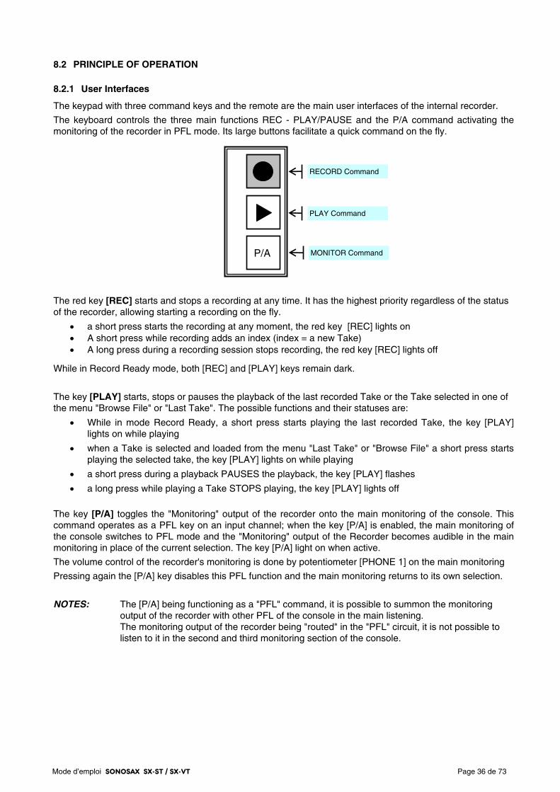
Mode d’emploi SONOSAX SX-ST / SX-VT Page 36 de 73
8.2 PRINCIPLE OF OPERATION
8.2.1 User Interfaces
The keypad with three command keys and the remote are the main user interfaces of the internal recorder.
The keyboard controls the three main functions REC - PLAY/PAUSE and the P/A command activating the monitoring of the recorder in PFL mode. Its large buttons facilitate a quick command on the fly.
The red key [REC] starts and stops a recording at any time. It has the highest priority regardless of the status of the recorder, allowing starting a recording on the fly.
• a short press starts the recording at any moment, the red key [REC] lights on • A short press while recording adds an index (index = a new Take) • A long press during a recording session stops recording, the red key [REC] lights off
While in Record Ready mode, both [REC] and [PLAY] keys remain dark.
The key [PLAY] starts, stops or pauses the playback of the last recorded Take or the Take selected in one of the menu "Browse File" or "Last Take". The possible functions and their statuses are:
• While in mode Record Ready, a short press starts playing the last recorded Take, the key [PLAY] lights on while playing
• when a Take is selected and loaded from the menu "Last Take" or "Browse File" a short press starts playing the selected take, the key [PLAY] lights on while playing
• a short press during a playback PAUSES the playback, the key [PLAY] flashes
• a long press while playing a Take STOPS playing, the key [PLAY] lights off
The key [P/A] toggles the "Monitoring" output of the recorder onto the main monitoring of the console. This command operates as a PFL key on an input channel; when the key [P/A] is enabled, the main monitoring of the console switches to PFL mode and the "Monitoring" output of the Recorder becomes audible in the main monitoring in place of the current selection. The key [P/A] light on when active.
The volume control of the recorder's monitoring is done by potentiometer [PHONE 1] on the main monitoring
Pressing again the [P/A] key disables this PFL function and the main monitoring returns to its own selection.
NOTES: The [P/A] being functioning as a "PFL" command, it is possible to summon the monitoring output of the recorder with other PFL of the console in the main listening. The monitoring output of the recorder being "routed" in the "PFL" circuit, it is not possible to listen to it in the second and third monitoring section of the console.
P/A MONITOR Command
RECORD Command
PLAY Command
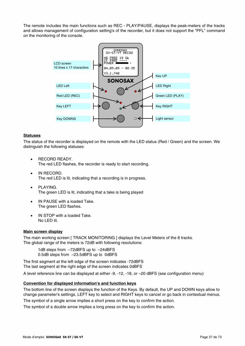
Mode d’emploi SONOSAX SX-ST / SX-VT Page 37 de 73
The remote includes the main functions such as REC - PLAY/PAUSE, displays the peak-meters of the tracks and allows management of configuration setting's of the recorder, but it does not support the "PFL" command on the monitoring of the console.
Statuses
The status of the recorder is displayed on the remote with the LED status (Red / Green) and the screen. We distinguish the following statuses:
• RECORD READY. The red LED flashes, the recorder is ready to start recording.
• IN RECORD. The red LED is lit, indicating that a recording is in progress.
• PLAYING. The green LED is lit, indicating that a take is being played
• IN PAUSE with a loaded Take. The green LED flashes.
• IN STOP with a loaded Take. No LED lit.
Main screen display
The main working screen [ TRACK MONITORING ] displays the Level Meters of the 8 tracks. The global range of the meters is 72dB with following resolutions:
1dB steps from –72dBFS up to –24dBFS 0.5dB steps from –23.5dBFS up to 0dBFS
The first segment at the left edge of the screen indicates -72dBFS The last segment at the right edge of the screen indicates 0dBFS
A level reference line can be displayed at either -9, -12, -18, or –20 dBFS (see configuration menu) Convention for displayed information's and function keys
The bottom line of the screen displays the function of the Keys. By default, the UP and DOWN keys allow to change parameter's settings, LEFT key to select and RIGHT keys to cancel or go back in contextual menus.
The symbol of a single arrow implies a short press on the key to confirm the action.
The symbol of a double arrow implies a long press on the key to confirm the action.
SONOSAX
Light sensor
LCD screen 10 lines x 17 characters
Key RIGHT
Key UP
Key DOWNS
LED Right LED Left
Key LEFT
Red LED (REC) Green LED (PLAY)
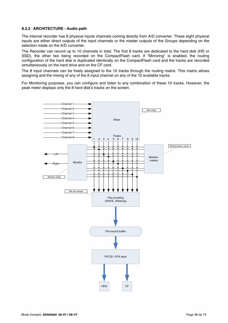
Mode d’emploi SONOSAX SX-ST / SX-VT Page 38 de 73
8.2.2 ARCHITECTURE - Audio path
The internal recorder has 8 physical inputs channels coming directly from A/D converter. These eight physical inputs are either direct outputs of the input channels or the master outputs of the Groups depending on the selection made on the A/D converter.
The Recorder can record up to 10 channels in total. The first 8 tracks are dedicated to the hard disk (HD or SSD), the other two being recorded on the CompactFlash card. If "Mirroring" is enabled, the routing configuration of the hard disk is duplicated identically on the CompactFlash card and the tracks are recorded simultaneously on the hard drive and on the CF card.
The 8 input channels can be freely assigned to the 10 tracks through the routing matrix. This matrix allows assigning and the mixing of any of the 8 input channel on any of the 10 available tracks.
For Monitoring purposes, you can configure and listen to any combination of these 10 tracks. However, the peak meter displays only the 8 hard disk's tracks on the screen.
Channel 1
Channel 2
Channel 3
Channel 4
Channel 5
Channel 6
Channel 7
Channel 8
Mix config
Left
Monitor config
Right
Bits per sample
HDD CF
Modulometers values
Mixer
Tracks1 2 3 4 5 6 7 8 9 10
Modulo-meters
Monitor
File encoding(WAVE, dithering)
Pre-record buffer
FAT32 / ATA layer
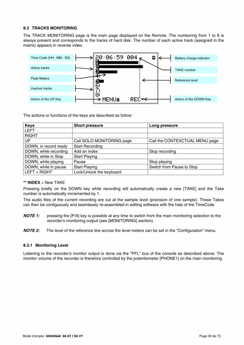
Mode d’emploi SONOSAX SX-ST / SX-VT Page 39 de 73
8.3 TRACKS MONITORING
The TRACK MONITORING page is the main page displayed on the Remote. The numbering from 1 to 8 is always present and corresponds to the tracks of hard disk. The number of each active track (assigned in the matrix) appears in reverse video
The actions or functions of the keys are described as follow: Keys Short pressure Long pressure LEFT RIGHT UP Call SOLO MONITORING page Call the CONTEXCTUAL MENU page DOWN, in record ready Start Recording DOWN, while recording Add an index Stop recording DOWN, while in Stop Start Playing DOWN, while playing Pause Stop playing DOWN, while in pause Start Playing Switch from Pause to Stop LEFT + RIGHT Lock/Unlock the keyboard
** INDEX = New TAKE
Pressing briefly on the DOWN key while recording will automatically create a new [TAKE] and the Take number is automatically incremented by 1.
The audio files of the current recording are cut at the sample level (precision of one sample). These Takes can then be contiguously and seamlessly re-assembled in editing software with the help of the TimeCode
NOTE 1: pressing the [P/A] key is possible at any time to switch from the main monitoring selection to the
recorder's monitoring output (see [MONITORING] section). NOTE 2: The level of the reference line across the level meters can be set in the "Configuration" menu.
8.3.1 Monitoring Level
Listening to the recorder's monitor output is done via the "PFL" bus of the console as described above. The monitor volume of the recorder is therefore controlled by the potentiometer [PHONE1] on the main monitoring.
Time Code (HH : MM : SS)
Peak Meters
Active tracks
Inactive tracks
Reference level
TAKE number
Battery charge indicator
Action of the UP Key Action of the DOWN Key
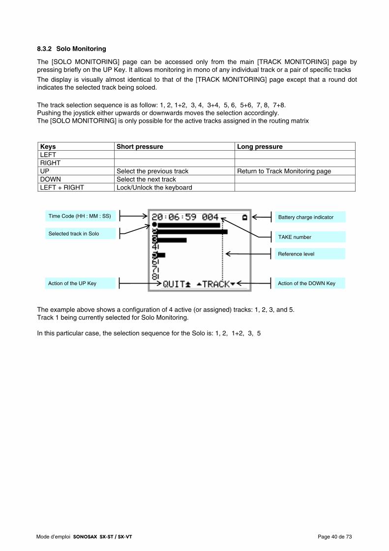
Mode d’emploi SONOSAX SX-ST / SX-VT Page 40 de 73
8.3.2 Solo Monitoring
The [SOLO MONITORING] page can be accessed only from the main [TRACK MONITORING] page by pressing briefly on the UP Key. It allows monitoring in mono of any individual track or a pair of specific tracks
The display is visually almost identical to that of the [TRACK MONITORING] page except that a round dot indicates the selected track being soloed.
The track selection sequence is as follow: 1, 2, 1+2, 3, 4, 3+4, 5, 6, 5+6, 7, 8, 7+8. Pushing the joystick either upwards or downwards moves the selection accordingly. The [SOLO MONITORING] is only possible for the active tracks assigned in the routing matrix
Keys Short pressure Long pressure LEFT RIGHT UP Select the previous track Return to Track Monitoring page DOWN Select the next track LEFT + RIGHT Lock/Unlock the keyboard
The example above shows a configuration of 4 active (or assigned) tracks: 1, 2, 3, and 5. Track 1 being currently selected for Solo Monitoring. In this particular case, the selection sequence for the Solo is: 1, 2, 1+2, 3, 5
Time Code (HH : MM : SS)
Reference level
TAKE number
Battery charge indicator
Selected track in Solo
Action of the UP Key Action of the DOWN Key
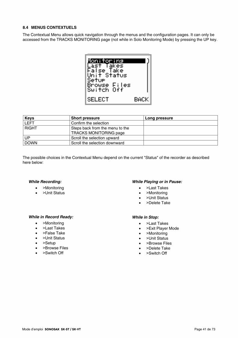
Mode d’emploi SONOSAX SX-ST / SX-VT Page 41 de 73
8.4 MENUS CONTEXTUELS
The Contextual Menu allows quick navigation through the menus and the configuration pages. It can only be accessed from the TRACKS MONITORING page (not while in Solo Monitoring Mode) by pressing the UP key.
Keys Short pressure Long pressure LEFT Confirm the selection RIGHT Steps back from the menu to the
TRACKS MONITORING page
UP Scroll the selection upward DOWN Scroll the selection downward
The possible choices in the Contextual Menu depend on the current "Status" of the recorder as described here below:
While Recording:
• >Monitoring • >Unit Status
While in Record Ready:
• >Monitoring • >Last Takes • >False Take • >Unit Status • >Setup • >Browse Files • >Switch Off
While Playing or in Pause:
• >Last Takes • >Monitoring • >Unit Status • >Delete Take
While in Stop:
• >Last Takes • >Exit Player Mode • >Monitoring • >Unit Status • >Browse Files • >Delete Take • >Switch Off
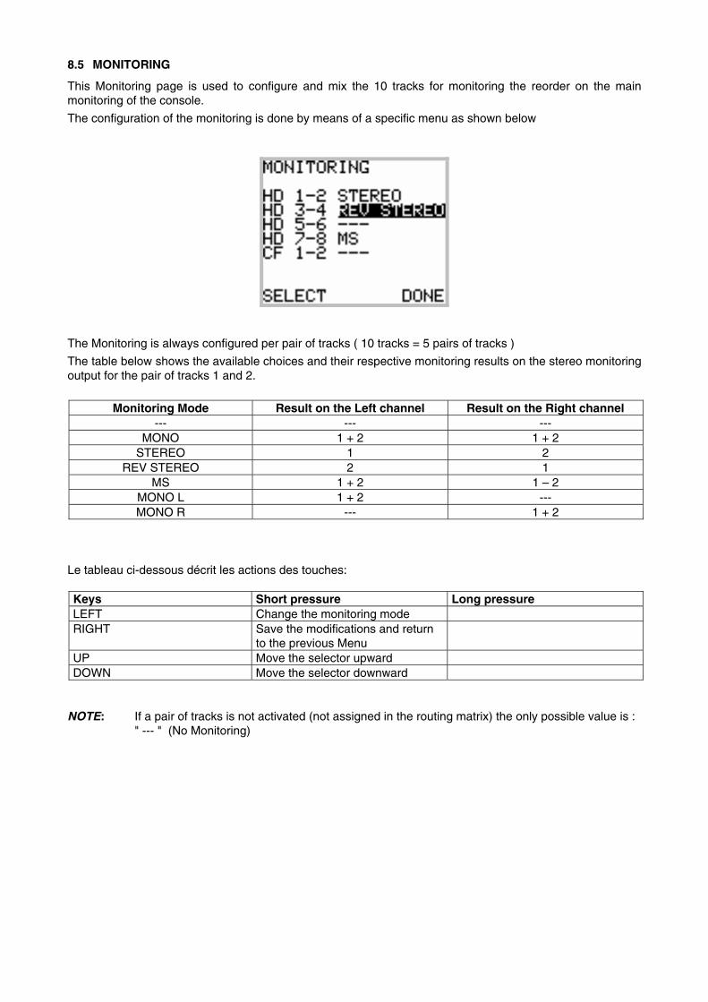
8.5 MONITORING
This Monitoring page is used to configure and mix the 10 tracks for monitoring the reorder on the main monitoring of the console.
The configuration of the monitoring is done by means of a specific menu as shown below
The Monitoring is always configured per pair of tracks ( 10 tracks = 5 pairs of tracks )
The table below shows the available choices and their respective monitoring results on the stereo monitoring output for the pair of tracks 1 and 2.
Monitoring Mode Result on the Left channel Result on the Right channel
--- --- --- MONO 1 + 2 1 + 2
STEREO 1 2 REV STEREO 2 1
MS 1 + 2 1 – 2 MONO L 1 + 2 --- MONO R --- 1 + 2
Le tableau ci-dessous décrit les actions des touches: Keys Short pressure Long pressure LEFT Change the monitoring mode RIGHT Save the modifications and return
to the previous Menu
UP Move the selector upward DOWN Move the selector downward
NOTE: If a pair of tracks is not activated (not assigned in the routing matrix) the only possible value is :
" --- " (No Monitoring)
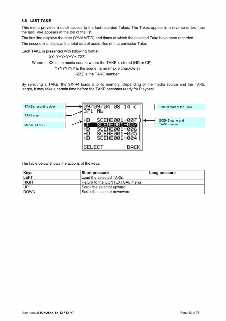
User manual SONOSAX SX-SX / SX-VT Page 43 of 73
8.6 LAST TAKE
This menu provides a quick access to the last recorded Takes. The Takes appear in a reverse order, thus the last Take appears at the top of the list.
The first line displays the date (YY/MM/DD) and times at which the selected Take have been recorded.
The second line displays the total size of audio files of that particular Take.
Each TAKE is presented with following format:
XX YYYYYYYY-ZZZ
Where : XX is the media source where the TAKE is stored (HD or CF)
YYYYYYYY is the scene name (max 8 characters)
-ZZZ is the TAKE number
By selecting a TAKE, the SX-R4 loads it to its memory. Depending of the media source and the TAKE length, it may take a certain time before the TAKE becomes ready for Playback.
The table below shows the actions of the keys: Keys Short pressure Long pressure LEFT Load the selected TAKE RIGHT Return to the CONTEXTUAL menu UP Scroll the selector upward DOWN Scroll the selector downward
TAKE's recording date
TAKE size
Media HD or CF
SCENE name and TAKE number
Time at start of the TAKE
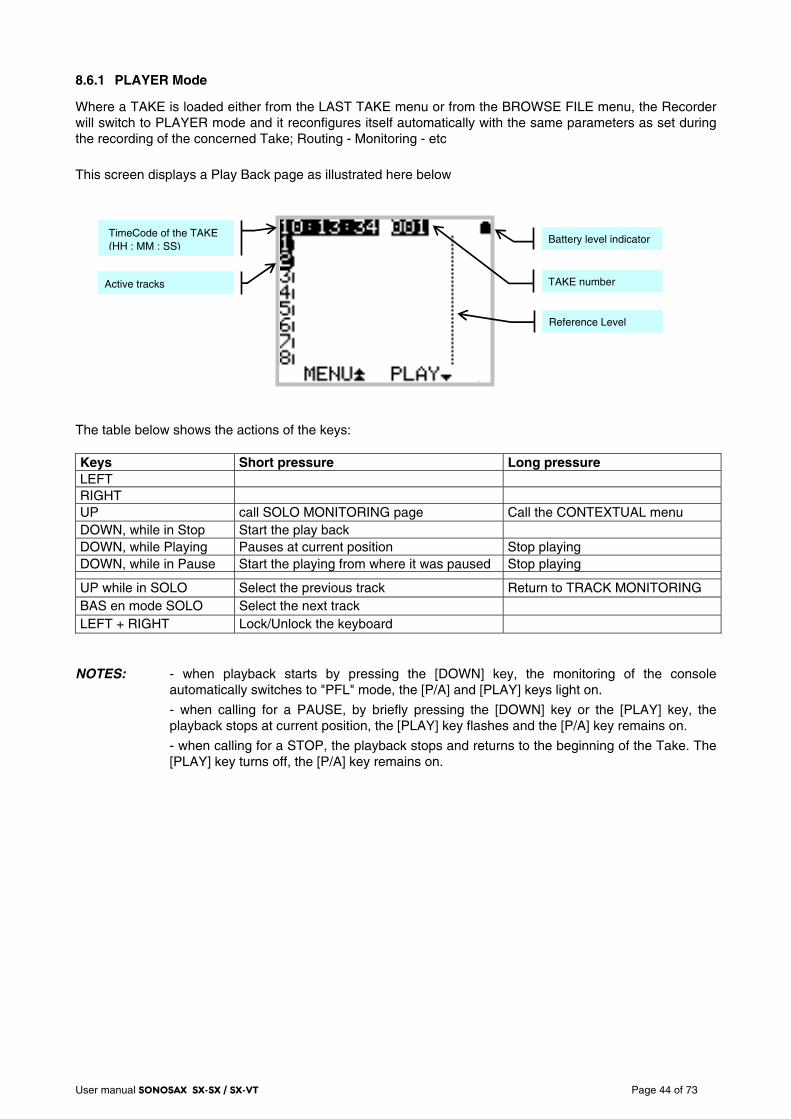
User manual SONOSAX SX-SX / SX-VT Page 44 of 73
8.6.1 PLAYER Mode
Where a TAKE is loaded either from the LAST TAKE menu or from the BROWSE FILE menu, the Recorder will switch to PLAYER mode and it reconfigures itself automatically with the same parameters as set during the recording of the concerned Take; Routing - Monitoring - etc
This screen displays a Play Back page as illustrated here below The table below shows the actions of the keys: Keys Short pressure Long pressure LEFT RIGHT UP call SOLO MONITORING page Call the CONTEXTUAL menu DOWN, while in Stop Start the play back DOWN, while Playing Pauses at current position Stop playing DOWN, while in Pause Start the playing from where it was paused Stop playing
UP while in SOLO Select the previous track Return to TRACK MONITORING BAS en mode SOLO Select the next track LEFT + RIGHT Lock/Unlock the keyboard
NOTES: - when playback starts by pressing the [DOWN] key, the monitoring of the console
automatically switches to "PFL" mode, the [P/A] and [PLAY] keys light on.
- when calling for a PAUSE, by briefly pressing the [DOWN] key or the [PLAY] key, the playback stops at current position, the [PLAY] key flashes and the [P/A] key remains on.
- when calling for a STOP, the playback stops and returns to the beginning of the Take. The [PLAY] key turns off, the [P/A] key remains on.
TAKE number
Battery level indicator
Reference Level
TimeCode of the TAKE (HH : MM : SS)
Active tracks
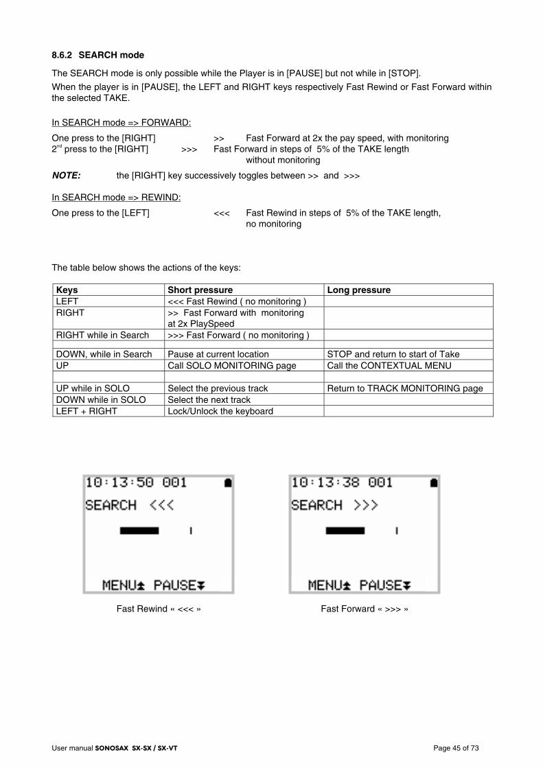
User manual SONOSAX SX-SX / SX-VT Page 45 of 73
8.6.2 SEARCH mode
The SEARCH mode is only possible while the Player is in [PAUSE] but not while in [STOP].
When the player is in [PAUSE], the LEFT and RIGHT keys respectively Fast Rewind or Fast Forward within the selected TAKE.
In SEARCH mode => FORWARD:
One press to the [RIGHT] >> Fast Forward at 2x the pay speed, with monitoring 2nd press to the [RIGHT] >>> Fast Forward in steps of 5% of the TAKE length without monitoring
NOTE: the [RIGHT] key successively toggles between >> and >>> In SEARCH mode => REWIND:
One press to the [LEFT] <<< Fast Rewind in steps of 5% of the TAKE length, no monitoring The table below shows the actions of the keys: Keys Short pressure Long pressure LEFT <<< Fast Rewind ( no monitoring ) RIGHT >> Fast Forward with monitoring
at 2x PlaySpeed
RIGHT while in Search >>> Fast Forward ( no monitoring )
DOWN, while in Search Pause at current location STOP and return to start of Take UP Call SOLO MONITORING page Call the CONTEXTUAL MENU UP while in SOLO Select the previous track Return to TRACK MONITORING page DOWN while in SOLO Select the next track LEFT + RIGHT Lock/Unlock the keyboard
Fast Rewind « <<< » Fast Forward « >>> »
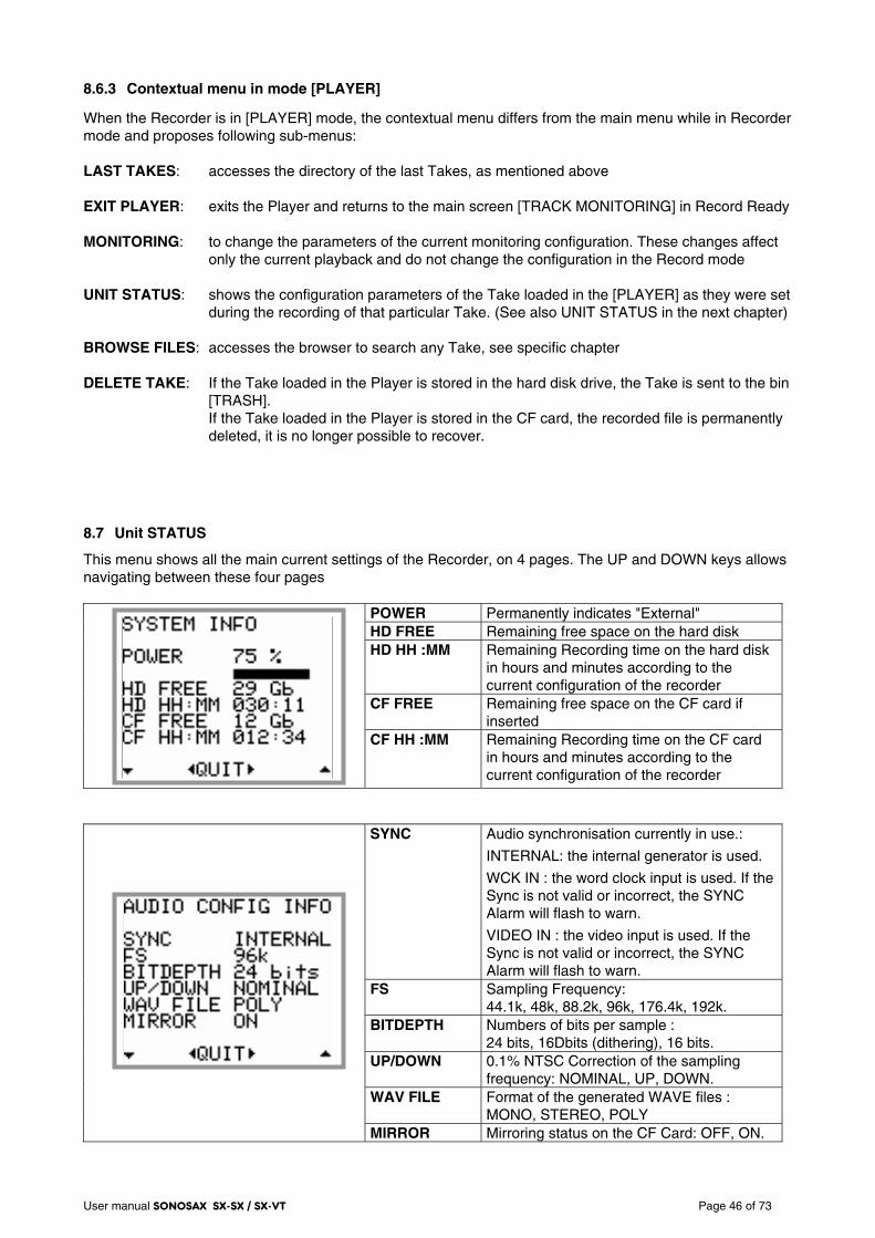
User manual SONOSAX SX-SX / SX-VT Page 46 of 73
8.6.3 Contextual menu in mode [PLAYER]
When the Recorder is in [PLAYER] mode, the contextual menu differs from the main menu while in Recorder mode and proposes following sub-menus: LAST TAKES: accesses the directory of the last Takes, as mentioned above EXIT PLAYER: exits the Player and returns to the main screen [TRACK MONITORING] in Record Ready MONITORING: to change the parameters of the current monitoring configuration. These changes affect
only the current playback and do not change the configuration in the Record mode
UNIT STATUS: shows the configuration parameters of the Take loaded in the [PLAYER] as they were set during the recording of that particular Take. (See also UNIT STATUS in the next chapter)
BROWSE FILES: accesses the browser to search any Take, see specific chapter DELETE TAKE: If the Take loaded in the Player is stored in the hard disk drive, the Take is sent to the bin
[TRASH]. If the Take loaded in the Player is stored in the CF card, the recorded file is permanently deleted, it is no longer possible to recover.
8.7 Unit STATUS
This menu shows all the main current settings of the Recorder, on 4 pages. The UP and DOWN keys allows navigating between these four pages
POWER Permanently indicates "External" HD FREE Remaining free space on the hard disk HD HH :MM Remaining Recording time on the hard disk
in hours and minutes according to the current configuration of the recorder
CF FREE Remaining free space on the CF card if inserted
CF HH :MM Remaining Recording time on the CF card in hours and minutes according to the current configuration of the recorder
SYNC Audio synchronisation currently in use.:
INTERNAL: the internal generator is used.
WCK IN : the word clock input is used. If the Sync is not valid or incorrect, the SYNC Alarm will flash to warn.
VIDEO IN : the video input is used. If the Sync is not valid or incorrect, the SYNC Alarm will flash to warn.
FS Sampling Frequency: 44.1k, 48k, 88.2k, 96k, 176.4k, 192k.
BITDEPTH Numbers of bits per sample : 24 bits, 16Dbits (dithering), 16 bits.
UP/DOWN 0.1% NTSC Correction of the sampling frequency: NOMINAL, UP, DOWN.
WAV FILE Format of the generated WAVE files : MONO, STEREO, POLY
MIRROR Mirroring status on the CF Card: OFF, ON.
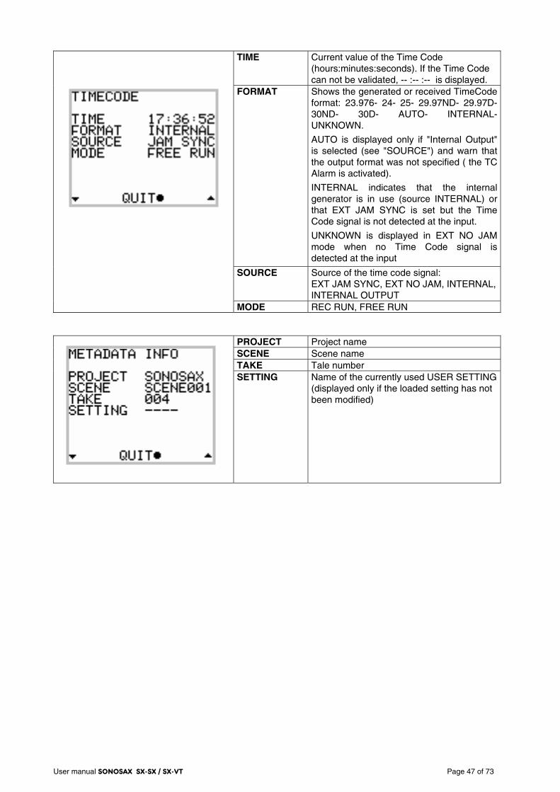
User manual SONOSAX SX-SX / SX-VT Page 47 of 73
TIME Current value of the Time Code
(hours:minutes:seconds). If the Time Code can not be validated, -- :-- :-- is displayed.
FORMAT Shows the generated or received TimeCode format: 23.976- 24- 25- 29.97ND- 29.97D-30ND- 30D- AUTO- INTERNAL- UNKNOWN.
AUTO is displayed only if "Internal Output" is selected (see "SOURCE") and warn that the output format was not specified ( the TC Alarm is activated).
INTERNAL indicates that the internal generator is in use (source INTERNAL) or that EXT JAM SYNC is set but the Time Code signal is not detected at the input.
UNKNOWN is displayed in EXT NO JAM mode when no Time Code signal is detected at the input
SOURCE Source of the time code signal: EXT JAM SYNC, EXT NO JAM, INTERNAL, INTERNAL OUTPUT
MODE REC RUN, FREE RUN
PROJECT Project name SCENE Scene name TAKE Tale number
SETTING Name of the currently used USER SETTING (displayed only if the loaded setting has not been modified)
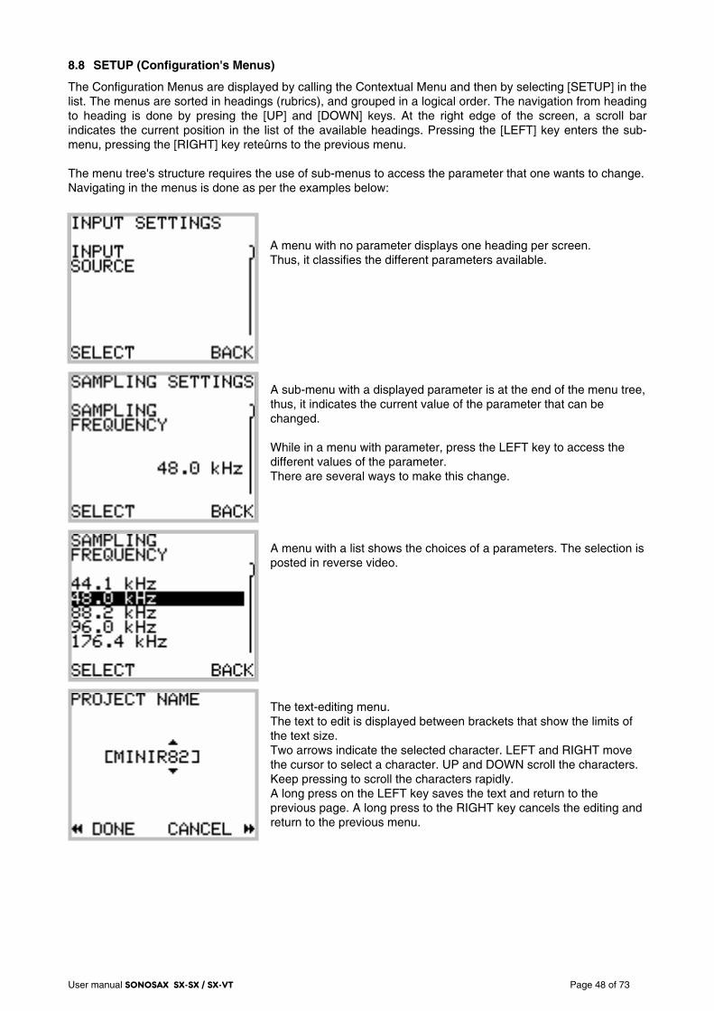
User manual SONOSAX SX-SX / SX-VT Page 48 of 73
8.8 SETUP (Configuration's Menus)
The Configuration Menus are displayed by calling the Contextual Menu and then by selecting [SETUP] in the list. The menus are sorted in headings (rubrics), and grouped in a logical order. The navigation from heading to heading is done by presing the [UP] and [DOWN] keys. At the right edge of the screen, a scroll bar indicates the current position in the list of the available headings. Pressing the [LEFT] key enters the sub-menu, pressing the [RIGHT] key reteûrns to the previous menu. The menu tree's structure requires the use of sub-menus to access the parameter that one wants to change. Navigating in the menus is done as per the examples below:
A menu with no parameter displays one heading per screen. Thus, it classifies the different parameters available. A sub-menu with a displayed parameter is at the end of the menu tree, thus, it indicates the current value of the parameter that can be changed. While in a menu with parameter, press the LEFT key to access the different values of the parameter. There are several ways to make this change. A menu with a list shows the choices of a parameters. The selection is posted in reverse video. The text-editing menu. The text to edit is displayed between brackets that show the limits of the text size. Two arrows indicate the selected character. LEFT and RIGHT move the cursor to select a character. UP and DOWN scroll the characters. Keep pressing to scroll the characters rapidly. A long press on the LEFT key saves the text and return to the previous page. A long press to the RIGHT key cancels the editing and return to the previous menu.
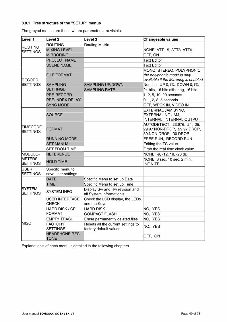
User manual SONOSAX SX-SX / SX-VT Page 49 of 73
8.8.1 Tree structure of the "SETUP" menus
The greyed menus are those where parameters are visible.
Level 1 Level 2 Level 3 Changeable values ROUTING Routing Matrix MIXING LEVEL NONE, ATT1.5, ATT3, ATT6
ROUTING SETTINGS
MIRRORING OFF, ON PROJECT NAME Text Editor SCENE NAME Text Editor
FILE FORMAT MONO, STEREO, POLYPHONIC the polyphonic mode is only available if the Mirroring is enabled
SAMPLING UP/DOWN Nominal, UP 0,1%, DOWN 0,1% SAMPLING SETTINGD SAMPLING RATE 24 bits, 16 bits dithering, 16 bits PRE-RECORD 1, 2, 5, 10, 20 seconds PRE-INDEX DELAY 0, 1, 2, 3, 5 seconds
RECORD SETTINGS
SYNC MODE OFF, WDCK IN, VIDEO IN
SOURCE EXTERNAL JAM SYNC, EXTERNAL NO JAM, INTERNAL, INTERNAL OUTPUT
FORMAT AUTODETECT, 23.976, 24, 25, 29.97 NON-DROP, 29.97 DROP, 30 NON-DROP, 30 DROP
RUNNING MODE FREE RUN, RECORD RUN SET MANUAL Editing the TC value
TIMECODE SETTINGS
SET FROM TIME Grab the real time clock value REFERENCE NONE, -9, -12, 18, -20 dB MODULO-
METERS SETTINGS HOLD TIME
NONE, 3 sec, 10 sec, 2 min, INFINITE
USER SETTINGS
Specific menu to save user settings
DATE Specific Menu to set up Date TIME Specific Menu to set up Time
SYSTEM INFO Display Sw and Hw revision and all System information's
SYSTEM SETTINGS
USER INTERFACE CHECK
Check the LCD display, the LEDs and the Keys
HARD DISK NO, YES HARD DISK / CF FORMAT COMPACT FLASH NO, YES EMPTY TRASH Erase permanently deleted files NO, YES FACTORY SETTINGS
Resets all the current settings to factory default values
NO, YES MISC
HEADPHONE REC TONE
OFF, ON
Explanation's of each menu is detailed in the following chapters.
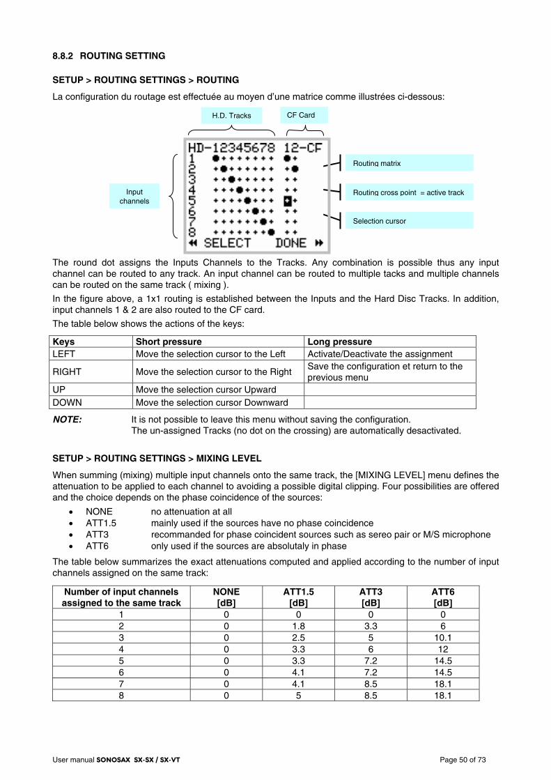
User manual SONOSAX SX-SX / SX-VT Page 50 of 73
8.8.2 ROUTING SETTING
SETUP > ROUTING SETTINGS > ROUTING
La configuration du routage est effectuée au moyen d’une matrice comme illustrées ci-dessous:
The round dot assigns the Inputs Channels to the Tracks. Any combination is possible thus any input channel can be routed to any track. An input channel can be routed to multiple tacks and multiple channels can be routed on the same track ( mixing ).
In the figure above, a 1x1 routing is established between the Inputs and the Hard Disc Tracks. In addition, input channels 1 & 2 are also routed to the CF card.
The table below shows the actions of the keys:
Keys Short pressure Long pressure LEFT Move the selection cursor to the Left Activate/Deactivate the assignment
RIGHT Move the selection cursor to the Right Save the configuration et return to the previous menu
UP Move the selection cursor Upward DOWN Move the selection cursor Downward
NOTE: It is not possible to leave this menu without saving the configuration. The un-assigned Tracks (no dot on the crossing) are automatically desactivated.
SETUP > ROUTING SETTINGS > MIXING LEVEL
When summing (mixing) multiple input channels onto the same track, the [MIXING LEVEL] menu defines the attenuation to be applied to each channel to avoiding a possible digital clipping. Four possibilities are offered and the choice depends on the phase coincidence of the sources:
• NONE no attenuation at all • ATT1.5 mainly used if the sources have no phase coincidence • ATT3 recommanded for phase coincident sources such as sereo pair or M/S microphone • ATT6 only used if the sources are absolutaly in phase
The table below summarizes the exact attenuations computed and applied according to the number of input channels assigned on the same track:
Number of input channels assigned to the same track
NONE [dB]
ATT1.5 [dB]
ATT3 [dB]
ATT6 [dB]
1 0 0 0 0 2 0 1.8 3.3 6 3 0 2.5 5 10.1 4 0 3.3 6 12 5 0 3.3 7.2 14.5 6 0 4.1 7.2 14.5 7 0 4.1 8.5 18.1 8 0 5 8.5 18.1
H.D. Tracks
Input channels
Routing matrix
Routing cross point = active track
Selection cursor
CF Card
User manual SONOSAX SX-SX / SX-VT Page 51 of 73
SETUP > ROUTING SETTINGS > MIRRORING
When the MIRRORING function is activated, the routing and the eventual mixing of the input channels onto the hard disk tracks is identically replicated on the Compact Flash card, providing that the performances of the CF card allow.
In MIRRORING mode, tracks 1 & 2 of the CF card will no longer appear in the routing matrix and are replaced by the word MIRROR
NOTE 1: Several series of tests with CF cards offering good performances helped to validate the
recording of up to 8 channels at 96kHz/24bit. If the performances of the CF card does not allow mirroring, a CF alarm will be displayed. The recording on the CF card will be aborted but will continue on the HD.
NOTE 2: If the storage capacity of the CF card is reached during recording, the CF card will stop recording but the recording will continue on the hard disk.
8.8.3 RECORD SETTINGS
SETUP > RECORD SETTINGS > PROJECT NAME
This menu allows you to set the PROJECT Name. It has several aims:
• Sets the name of the directory where the Takes will be stored. • Archives the Project name in each WAVE file (sub-chunk BWF and iXML)
The format of the Project Name is as follows:
• 8 characters maximum • alphanumeric characters, space and underscore only (A..Z, 0..9, _)
SETUP > RECORD SETTINGS > SCENE NAME
This menu allows you to set the SCENE Name. It has also several aims:
• Partially names the directory where the audio files of the Takes will be stored • Archives the Scene name in each WAVE file (sub-chunk BWF and iXML)
The format of the Project Name is as follows:
• 8 characters maximum • alphanumeric characters, space and underscore only (A..Z, 0..9, _)
SETUP > RECORD SETTINGS > FILE FORMAT
The File format offers three choices:
• MONO • STEREO • POLYPHONIC
If MONO is selected, each track is recorded in a separate mono file.
If STEREO is selected, the system records each pair of tracks in a single stereo file. The pairs are always 1+2, 3+4, 5+6 and 7+8. If the Routing sets incomplete pairs of tracks (eg tracks 1, 3, 4 and 7), every single track is recorded in a stereo file and occupies half the size of the file, the other half being a silent channel.
If POLYPHONIC mode is enabled, all active tracks are recorded in a single file. This mode is only possible if the MIRRORING mode is activated (see previous section), regardless of whether the Compact Flash card is present or not.
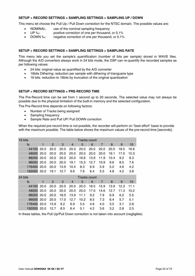
User manual SONOSAX SX-SX / SX-VT Page 52 of 73
SETUP > RECORD SETTINGS > SAMPLING SETTINGS > SAMPLING UP / DOWN
This menu let choose the Pull Up / Pull Down correction for the NTSC domain. The possible values are:
• NOMINAL: use of the nominal sampling frequency • UP ‰: positive correction of one per thousand, or 0,1% • DOWN ‰: negative correction of one per thousand, or 0,1%
SETUP > RECORD SETTINGS > SAMPLING SETTINGS > SAMPLING RATE
This menu lets you set the sample's quantification (number of bits per sample) stored in WAVE files. Although the A/D converters always work in 24 bits mode, the DSP can re-quantify the recorded samples as per following values:
• 24 bits: original value as quantified by the A/D converter • 16bits Dithering: reduction per sample with dithering of trianguaire type • 16 bits: reduction to 16bits by truncation of the original quantization
SETUP > RECORD SETTINGS > PRE-RECORD TIME
The Pre-Record time can be set from 1 second up to 20 seconds. The selected value may not always be possible due to the physical limitation of the built-in memory and the selected configuration.
The Pre-Record time depends on following factors:
• Number of Tracks being assigned • Sampling frequency • Sample Rate and Pull UP/ Pull DOWN correction
When the required pre-record time is not possible, the recorder will perform on "best effort" basis to provide with the maximum possible. The table below shows the maximum values of the pre-record time [seconds]:
16 bits Tracks count fs 1 2 3 4 5 6 7 8 9 10 44100 20.0 20.0 20.0 20.0 20.0 20.0 20.0 20.0 18.5 16.648000 20.0 20.0 20.0 20.0 20.0 20.0 20.0 19.1 17.0 15.388200 20.0 20.0 20.0 20.0 16.6 13.9 11.9 10.4 9.2 8.3 96000 20.0 20.0 20.0 19.1 15.3 12.7 10.9 9.6 8.5 7.6
176400 20.0 20.0 13.9 10.4 8.3 6.9 5.9 5.2 4.6 4.2 192000 20.0 19.1 12.7 9.6 7.6 6.4 5.5 4.8 4.2 3.8
24 bits Tracks count fs 1 2 3 4 5 6 7 8 9 10 44100 20.0 20.0 20.0 20.0 20.0 18.5 15.9 13.9 12.3 11.148000 20.0 20.0 20.0 20.0 20.0 17.0 14.6 12.7 11.3 10.288200 20.0 20.0 18.5 13.9 11.1 9.2 7.9 6.9 6.2 5.5 96000 20.0 20.0 17.0 12.7 10.2 8.5 7.3 6.4 5.7 5.1
176400 20.0 13.9 9.2 6.9 5.5 4.6 4.0 3.5 3.1 2.8 192000 20.0 12.7 8.5 6.4 5.1 4.2 3.6 3.2 2.8 2.5
In these tables, the Pull Up/Pull Down correction is not taken into account (negligible).
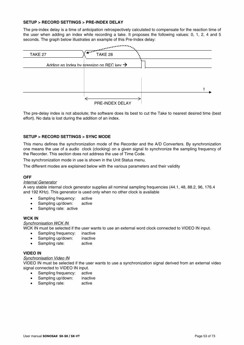
User manual SONOSAX SX-SX / SX-VT Page 53 of 73
SETUP > RECORD SETTINGS > PRE-INDEX DELAY
The pre-index delay is a time of anticipation retrospectively calculated to compensate for the reaction time of the user when adding an index while recording a take. It proposes the following values: 0, 1, 2, 4 and 5 seconds. The graph below illustrates an example of this Pre-Index delay:
The pre-delay index is not absolute; the software does its best to cut the Take to nearest desired time (best effort). No data is lost during the addition of an index.
SETUP > RECORD SETTINGS > SYNC MODE
This menu defines the synchronization mode of the Recorder and the A/D Converters. By synchronization one means the use of a audio clock (clocking) on a given signal to synchronize the sampling frequency of the Recorder. This section does not address the use of Time Code.
The synchronization mode in use is shown in the Unit Status menu.
The different modes are explained below with the various parameters and their validity
OFF Internal Generator A very stable internal clock generator supplies all nominal sampling frequencies (44.1, 48, 88.2, 96, 176.4 and 192 KHz). This generator is used only when no other clock is available
• Sampling frequency: active • Sampling up/down: active • Sampling rate: active
WCK IN Synchronisation WCK IN WCK IN must be selected if the user wants to use an external word clock connected to VIDEO IN input.
• Sampling frequency: inactive • Sampling up/down: inactive • Sampling rate: active
VIDEO IN Synchronisation Video IN VIDEO IN must be selected if the user wants to use a synchronization signal derived from an external video signal connected to VIDEO IN input.
• Sampling frequency: active • Sampling up/down: inactive • Sampling rate: active
t
TAKE 28 TAKE 27
Adding an Index by pressing on REC key
PRE-INDEX DELAY
User manual SONOSAX SX-SX / SX-VT Page 54 of 73
8.8.4 TIME CODE SETTINGS
SETUP > TIMECODE SETTINGS > SOURCE
The Recorder can either receive or generate a TimeCode. This menu lets you choose between an external TimeCode source and its own internal TimeCode generator. Its working mode as described below
• External Jam Sync • External No Jam • Internal the TC is generated but its output is disabled on the Lemo 5 pin connector • Internal Output the TC is generated and is available on the Lemo 5 pin connector
NOTE 1: while selecting "Internal Output", then a frame rate other than "Autodetect" must be selected in the TimeCode Input Format menu. If "Autodetect" is selected, then a warning will be posted on the screen.
NOTE 2: while in PLAYER mode, if "Internal Output" is selected, then the TimeCode at the output is
the TimeCode of the played file.
SETUP > TIMECODE SETTINGS > INPUT FORMAT
The Recorder can automatically detect the TimeCode format applied at the input of the TC connector. However, to be sure to use the correct format, it is possible to specify its value. In this case, the detection of a different format than specified, or a time code out of tolerance, triggers an alarm. The choices of TimeCode formats are:
• Autodetect • 23.976 • 24 • 25 • 29.97 Non Drop • 29.97 Drop • 30 Non Drop • 30 Drop
SETUP > TIMECODE SETTINGS > RUNNING MODE
Two possible choices:
• FREE RUN • RECORD RUN
In FREE RUN mode, the Time Code is absolute and linear. It runs continuously and never stops. In RECORD RUN, mode, the Time Code is generated only while recording.
SETUP > TIMECODE SETTINGS > SET MANUAL
Use this menu to set the TimeCode value manually.
SETUP > TIMECODE SETTINGS > SET FROM TIME
The value of the TimeCode address is adjusted exactly on the time of real time clock of the recorder.

User manual SONOSAX SX-SX / SX-VT Page 55 of 73
8.8.5 MODULOMETERS
SETUP > MODULOMETERS SETTINGS > REFERENCE
This menu allows setting and displaying a vertical line corresponding to a reference level for the peak meters on the TRACK MONITORING page. The reference is configurable:
• NONE • - 9 dB • -12 dB • -18 dB • -20 dB
SETUP > MODULOMETERS SETTINGS > HOLD TIME
The "Hold Time" function detects the absolute peak level and keeps it posted for:
• NONE • 3 seconds • 10 seconds • 2 minutes • INFINITE
8.8.6 USER SETTINGS
SETUP > USER SETTINGS
The "User Settings" menu allows to save, to load or to update a complete configuration to/from an ASCII file.
CREATE NEW
Create a new configuration file based on the current (active) configuration of the Recorder.
The format of the name is as follow:
8 characters maximum; alphanumeric characters, space and underscore only (A..Z, 0..9, _)
RECALL SELECTED
Load the selected configuration file. Caution: this operation will crush the current configuration!
DELETE SELECTED
Delete the selected configuration file.
OVERWRITE SELECTED
Overwrite the file of an existing setting by the current configuration of the Recorder.
User manual SONOSAX SX-SX / SX-VT Page 56 of 73
8.8.7 SYSTEM SETTINGS
This menu lets set the date and time of the internal "Real Time" clock of the Recorder, check the software and hardware revisions of the system, monitor and test the user interface the unit.
SETUP > SYSTEM SETTINGS > DATE
Set the date of the internal "Real Time" clock (format DD.MM.YYYY). Press on the LEFT key to select a parameter, UP and DOWN to scroll values Keep pressing on the LEFT key to validate and store the value. Keep pressing on the RIGHT key to return to the previous menu without changing the values (CANCEL)).
SETUP > SYSTEM SETTINGS > TIME
Set the time of the internal "Real Time" clock (format HH:MM:SS). Press on the LEFT key to select a parameter, UP and DOWN to scroll values Keep pressing on the LEFT key to validate and store the value. Keep pressing on the RIGHT key to return to the previous menu without changing the values (CANCEL)).
SETUP > SYSTEM SETTINGS > SYSTEM INFO
This menu displays the software and hardware revisions of the Recorder:
DSP software version, version of display's microcontroller (PIC), and CPLD interface.
Hardware version's of the AES receivers.
Type of flash memory detected (internal hardware).
The total sizes of the hard drive and Compact Flash card.
The frequency of the reference audio clock.
SETUP > SYSTEM SETTINGS > USER INTERFACE CHECK
This menu is to check the Keys, the LCD display, and the LED's. . Keys Short pressure Long pressure LEFT Test the Key and the Led on the Left RIGHT Test the Key and the Led on the Right UP Test the Up key and the Red Led DOWN Test the Down key and the Green Led UP and DOWN Return to previous menu
User manual SONOSAX SX-SX / SX-VT Page 57 of 73
8.8.8 MISC (Miscellaneous)
This menu contains some utilities for managing the internal hard disk disks and the compact flash card and a hearing witness of the recording start / stop
SETUP > MISC > HARD DISK / CF FORMAT
This screen provides access to a sub menu for formatting the HDD and/or the Compact Flash card. Select the media to be formatted using UP or DOWN key then press on the LEFT key to access the formatting utility. A new screen appears indicating the selected media and asking you to confirm formatting.
Select NO and press the RIGHT key to cancel formatting and return to the previous screen
Select YES and press the LEFT key to confirm formatting. The message "PLEASE WAIT" is posted on the screen during the formatting procedure, followed by a message "FORMAT SUCCESSFULL" confirming that the formatting is completed
WARNING: this function is irreversible and all table data of the FAT32 table will be erased.
NOTE 1: Reformatting the HDD or the CF card only erases the allocation table (known as fast format) and it will not be possible to access datas and files stored on the media. A so called low level formatting is unnecessary and does not to improve hard disk performance.
NOTE 2: when reformatting the hard drive, the "USER SETTINGS" files and the system file named CONFIG.DAT are temporarily copied to the memory of the Recorder and then restored on the hard disk when formatting process is completed. None of these files will be lost and it is not necessary to save these files on a computer.
SETUP > MISC > EMPTY TRASH
When one or more files are deleted (see Section PLAYER mode), they are not directly erased from the hard drive but moved and kept in Trash bin. If the remaining free space on the hard disk becomes insufficient for new takes, it is possible to recover some free disk space by emptying the trash. All files will be permanently deleted and will no longer be possible to recover. Select NO and press the RIGHT key to cancel this action and return to the previous screen.
Select YES and press the LEFT key to confirm the action The message "PLEASE WAIT" appears on the screen while erasing the files, and then the previous screen.
NOTE: When a file is deleted from the Compact Flash, it is not stored in the bin but it is immediately and permanently deleted.
SETUP > MISC > FACTORY SETTINGS
This menu allows re-initializing the Recorder to its basic configuration (factory default setting). This will overwrite the current configuration but does not alter the audio data on the disks or the "User Settings"
Select NO and press the RIGHT key to cancel this action and return to the previous screen.
Select YES and press the LEFT key to load the factory default configuration and return to the main "Track Monitoring" screen.
SETUP > MISC > HEADPHONE REC TONE
The start and stop recording can be witnessed in the headphones with a confidence beep tone. Start recording is signalled by a single beep tone and stop recording is signalled by a two tone's double beep.
Select ON to activate the beep tone; select OFF to cancel the beep tone
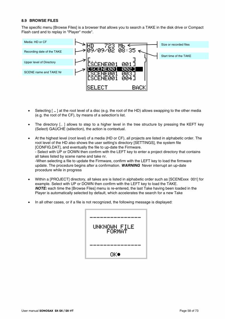
User manual SONOSAX SX-SX / SX-VT Page 58 of 73
8.9 BROWSE FILES
The specific menu [Browse Files] is a browser that allows you to search a TAKE in the disk drive or Compact Flash card and to replay in "Player" mode".
• Selecting [ .. ] at the root level of a disc (e.g. the root of the HD) allows swapping to the other media
(e.g. the root of the CF), by means of a selection's list.
• The directory [.. ] allows to step to a higher level in the tree structure by pressing the KEFT key (Select) GAUCHE (sélection), the action is contextual.
• At the highest level (root level) of a media (HD or CF), all projects are listed in alphabetic order. The
root level of the HD also shows the user setting's directory [SETTINGS], the system file [CONFIG.DAT], and eventually the file to up-date the Firmware. - Select with UP or DOWN then confirm with the LEFT key to enter a project directory that contains all takes listed by scene name and take nr. -When selecting a file to update the Firmware, confirm with the LEFT key to load the firmware update. The procedure begins after a confirmation. WARNING Never interrupt an up-date procedure while in progress
• Within a [PROJECT] directory, all takes are is listed in alphabetic order such as [SCENExxx 001] for example. Select with UP or DOWN then confirm with the LEFT key to load the TAKE. NOTE: each time the [Browse Files] menu is re-entered, the last Take having been loaded in the Player is automatically selected by default, which accelerates the search for a new Take
• In all other cases, or if a file is not recognized, the following message is displayed:
Media: HD or CF
Recording date of the TAKE
Size or recorded files
Upper level of Directory
SCENE name and TAKE Nr
Start time of the TAKE
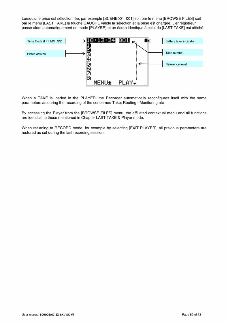
User manual SONOSAX SX-SX / SX-VT Page 59 of 73
Lorsqu'une prise est sélectionnée, par exemple [SCENE001 001] soit par le menu [BROWSE FILES] soit par le menu [LAST TAKE] la touche GAUCHE valide la sélection et la prise est chargée. L'enregistreur passe alors automatiquement en mode [PLAYER] et un écran identique à celui du [LAST TAKE] est affiché.
When a TAKE is loaded in the PLAYER, the Recorder automatically reconfigures itself with the same parameters as during the recording of the concerned Take; Routing - Monitoring etc
By accessing the Player from the [BROWSE FILES] menu, the affiliated contextual menu and all functions are identical to those mentioned in Chapter LAST TAKE & Player mode.
When returning to RECORD mode, for example by selecting [EXIT PLAYER], all previous parameters are restored as set during the last recording session.
Time Code (HH :MM :SS)
Pistes actives
Reference level
Take number
Battery level indicator
User manual SONOSAX SX-SX / SX-VT Page 60 of 73
9. Managing the Recorder
9.1.1 Formatting the HardDisk and CompactFlash card
Internal Hard Disk
The hard disk is factory formatted as a single FAT32 partition. Since version 2.6 of the firmware, the Recorder offers a formatting utility that manages perfectly the User Settings and the "CONFIG.DAT" system file while formatting (see chapter MISC). It is therefore recommended not to split the drive into multiple partitions, so as to ensure better compatibility with the MacOS system that does not – or badly - support multiple FAT32 partitions.
To re-format the internal hard drive, it is recommended to use the utility tool of the recorder. A low level formatting is unnecessary and does not improve disk performance
CompactFlash Card
Before its initial use, all new CF card must always be formatted in FAT32 - preferably with the "Low Level" formatting mode - to be recognized by the recorder.
Once the CF card has been correctly formatted, using a computer is no longer necessary and it is recommended to use the utility tool of the SX-R4 for subsequent re-formatting the CF card
9.1.2 Fragmentation de l'espace libre du disque dur
During heavy use of the recorder, it may be necessary to recover some free disk space by deleting audio files (Delete Take) and then erasing these files (Empty Trash) or to remove them when connected to a computer. This may lead to severe fragmentation of the free space on the hard drive or on the CF card which may prevent the recording of new Takes.
In this case an alarm HD or CF is posted to warn you of the problem. It is then necessary to back-up all your files and to reformat the disk using the SX-R4 format utility.
WARNING: UNDER NO CIRCUMSTANCES DO DEFRAGMENT THE INTERNAL HARD DISK OR THE CF CARD USING A DISC DEFRAGMENTATION UTILITY OR THE RECORDER WILL NO LONGER BE ABLE TO PLAY THE AUDIO FILES.
Important notes for MAC OSX users:
When deleting files stored on the Hard disk and/or on the CF, do not forget to empty the Trash Bin on your desktop before disconnecting the USB port. Otherwise, the disk space of the deleted files is not released and can not be re-allocated. Reconnecting the USB a second time doesn't solve the problem. It is very likely that the Recorder will then indicates a free available space "HD FREE" lower than the value given by the computer. In this case it will be necessary to save all your files and to reformat your hard drive by means of the formatting utility of the Recoder.
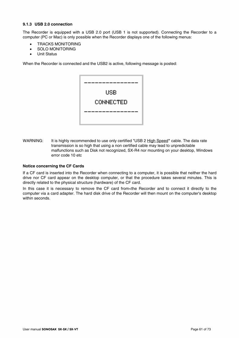
User manual SONOSAX SX-SX / SX-VT Page 61 of 73
9.1.3 USB 2.0 connection
The Recorder is equipped with a USB 2.0 port (USB 1 is not supported). Connecting the Recorder to a computer (PC or Mac) is only possible when the Recorder displays one of the following menus:
• TRACKS MONITORING • SOLO MONITORING • Unit Status
When the Recorder is connected and the USB2 is active, following message is posted: WARNING: It is highly recommended to use only certified "USB 2 High Speed" cable. The data rate
transmission is so high that using a non certified cable may lead to unpredictable malfunctions such as Disk not recognized, SX-R4 nor mounting on your desktop, Windows error code 10 etc
Notice concerning the CF Cards
If a CF card is inserted into the Recorder when connecting to a computer, it is possible that neither the hard drive nor CF card appear on the desktop computer, or that the procedure takes several minutes. This is directly related to the physical structure (hardware) of the CF card.
In this case it is necessary to remove the CF card from<the Recorder and to connect it directly to the computer via a card adapter. The hard disk drive of the Recorder will then mount on the computer's desktop within seconds.
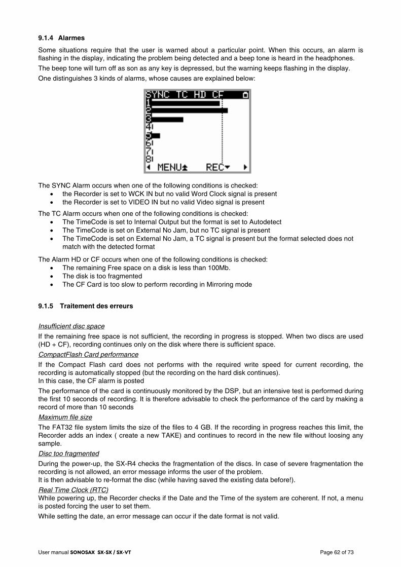
User manual SONOSAX SX-SX / SX-VT Page 62 of 73
9.1.4 Alarmes
Some situations require that the user is warned about a particular point. When this occurs, an alarm is flashing in the display, indicating the problem being detected and a beep tone is heard in the headphones.
The beep tone will turn off as son as any key is depressed, but the warning keeps flashing in the display.
One distinguishes 3 kinds of alarms, whose causes are explained below:
The SYNC Alarm occurs when one of the following conditions is checked:
• the Recorder is set to WCK IN but no valid Word Clock signal is present • the Recorder is set to VIDEO IN but no valid Video signal is present
The TC Alarm occurs when one of the following conditions is checked: • The TimeCode is set to Internal Output but the format is set to Autodetect • The TimeCode is set on External No Jam, but no TC signal is present • The TimeCode is set on External No Jam, a TC signal is present but the format selected does not
match with the detected format
The Alarm HD or CF occurs when one of the following conditions is checked: • The remaining Free space on a disk is less than 100Mb. • The disk is too fragmented • The CF Card is too slow to perform recording in Mirroring mode
9.1.5 Traitement des erreurs
Insufficient disc space
If the remaining free space is not sufficient, the recording in progress is stopped. When two discs are used (HD + CF), recording continues only on the disk where there is sufficient space.
CompactFlash Card performance
If the Compact Flash card does not performs with the required write speed for current recording, the recording is automatically stopped (but the recording on the hard disk continues). In this case, the CF alarm is posted
The performance of the card is continuously monitored by the DSP, but an intensive test is performed during the first 10 seconds of recording. It is therefore advisable to check the performance of the card by making a record of more than 10 seconds
Maximum file size
The FAT32 file system limits the size of the files to 4 GB. If the recording in progress reaches this limit, the Recorder adds an index ( create a new TAKE) and continues to record in the new file without loosing any sample.
Disc too fragmented
During the power-up, the SX-R4 checks the fragmentation of the discs. In case of severe fragmentation the recording is not allowed, an error message informs the user of the problem. It is then advisable to re-format the disc (while having saved the existing data before!).
Real Time Clock (RTC) While powering up, the Recorder checks if the Date and the Time of the system are coherent. If not, a menu is posted forcing the user to set them.
While setting the date, an error message can occur if the date format is not valid.
User manual SONOSAX SX-SX / SX-VT Page 63 of 73
9.1.6 Up-date procedure
Up dating the Firmware from the internal hard drive
1. Download the appropriate version from the website: www.sonosax.ch/software_download.html the file name of the Firmware will be: stxxxxxx.bin
2. Connect the recorder to the USB2 port of your computer and back up all your files.
3. Copy the Firmware file to the root directory of the hard drive then disconnect from the computer.
4. From the Main menu, enter the [BROWSE FILES] menu, locate the new Firmware file in the root directory of the hard disk drive and select the file.
5. A message will be prompted asking you to confirm the up-date procedure. Make sure that you have backed-up all your files before proceeding and then press OK to confirm the up-date procedure. A progression bar will appear indicating that the up-date is in progress. Please wait until completion; never turn off the unit during an up-date procedure.
6. Once completed, a message will be posted asking you to reboot the recorder.
7. Reformat the hard disk using the utility tool in the MISC menu: Main menu => Setup => MISC => Hard disk / CF Format => select Hard Drive => select YES the OK. A message "PLEASE WAIT" will be posted, followed by "FORMAT SUCCESSFULL" confirming that the formatting is completed. Press OK to continue.
8. IMPORTANT, before using your newly up-dated recorder, you must first reload the Factory default settings: Main menu => Setup => MISC => Factory Setting => select YES
9. Your recorder is now ready for use with its new Firmware. It is then possible to reload an existing setting from the [USER SETTINGS] directory.
Up dating the Firmware from the CF Card
Using a CF Card Up to up-date the Firmware is also possible:
1. Download the Firmware file as previously indicated under point nr 1.
2. Connect the CF Card to the computer using a card adapter and then copy the Firmware file to the root directory of the CF card.
3. Remove the CF card from the computer and insert the card in the Recorder.
4. From the Main menu, enter the [BROWSE FILES] menu and select the CF Card. Locate the new Firmware file in the root directory of the CF card and select the file.
5. Then proceeds as previously mentioned from point 5 to point 9 to complete the up-date procedure.
9.1.7 Recommendations
Due to the architecture of the Recorder and its operating system we suggest following recommendations:
Copying Takes It is strongly advised to copy (transfer) the Takes to the hard disc of a computer on a regular basis. The opposite is however not possible: the Rocorder is not able to read an audio file copied to its disc from a computer.
Defragmentation Never defragment the disks (HD, SSD or CF). For performance reasons, the recording is done by interlacing the various files that comprise it. These files must remain interlaced for the playback of the Take. In case of excessive fragmentation of a disk, you must save your data and format it (the quick format is sufficient).
Deleting files Deleting a file is possible, but it must always be carried out by Take (deletion of the Take directory only). The deletion of a project is possible too.
Formatting The Recorder works only with FAT32 file system. The setting of the clusters size can be left in their default value.
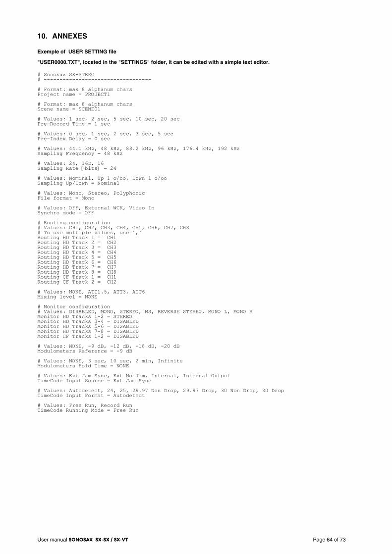
User manual SONOSAX SX-SX / SX-VT Page 64 of 73
10. ANNEXES
Exemple of USER SETTING file
"USER0000.TXT", located in the "SETTINGS" folder, it can be edited with a simple text editor. # Sonosax SX-STREC # ---------------------------------- # Format: max 8 alphanum chars Project name = PROJECT1 # Format: max 8 alphanum chars Scene name = SCENE01 # Values: 1 sec, 2 sec, 5 sec, 10 sec, 20 sec Pre-Record Time = 1 sec # Values: 0 sec, 1 sec, 2 sec, 3 sec, 5 sec Pre-Index Delay = 0 sec # Values: 44.1 kHz, 48 kHz, 88.2 kHz, 96 kHz, 176.4 kHz, 192 kHz Sampling Frequency = 48 kHz # Values: 24, 16D, 16 Sampling Rate [bits] = 24 # Values: Nominal, Up 1 o/oo, Down 1 o/oo Sampling Up/Down = Nominal # Values: Mono, Stereo, Polyphonic File format = Mono # Values: OFF, External WCK, Video In Synchro mode = OFF # Routing configuration # Values: CH1, CH2, CH3, CH4, CH5, CH6, CH7, CH8 # To use multiple values, use ',' Routing HD Track 1 = CH1 Routing HD Track 2 = CH2 Routing HD Track 3 = CH3 Routing HD Track 4 = CH4 Routing HD Track 5 = CH5 Routing HD Track 6 = CH6 Routing HD Track 7 = CH7 Routing HD Track 8 = CH8 Routing CF Track 1 = CH1 Routing CF Track 2 = CH2 # Values: NONE, ATT1.5, ATT3, ATT6 Mixing level = NONE # Monitor configuration # Values: DISABLED, MONO, STEREO, MS, REVERSE STEREO, MONO L, MONO R Monitor HD Tracks 1-2 = STEREO Monitor HD Tracks 3-4 = DISABLED Monitor HD Tracks 5-6 = DISABLED Monitor HD Tracks 7-8 = DISABLED Monitor CF Tracks 1-2 = DISABLED # Values: NONE, -9 dB, -12 dB, -18 dB, -20 dB Modulometers Reference = -9 dB # Values: NONE, 3 sec, 10 sec, 2 min, Infinite Modulometers Hold Time = NONE # Values: Ext Jam Sync, Ext No Jam, Internal, Internal Output TimeCode Input Source = Ext Jam Sync # Values: Autodetect, 24, 25, 29.97 Non Drop, 29.97 Drop, 30 Non Drop, 30 Drop TimeCode Input Format = Autodetect # Values: Free Run, Record Run TimeCode Running Mode = Free Run
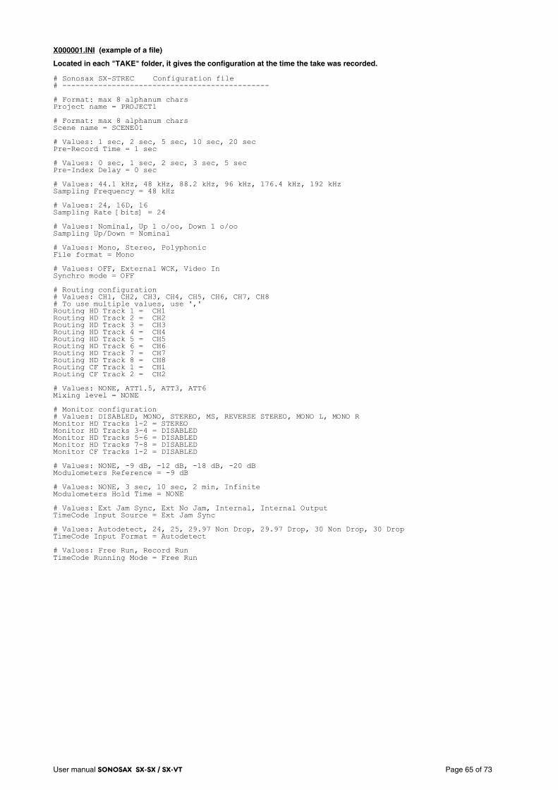
User manual SONOSAX SX-SX / SX-VT Page 65 of 73
X000001.INI (example of a file)
Located in each "TAKE" folder, it gives the configuration at the time the take was recorded. # Sonosax SX-STREC Configuration file # ---------------------------------------------- # Format: max 8 alphanum chars Project name = PROJECT1 # Format: max 8 alphanum chars Scene name = SCENE01 # Values: 1 sec, 2 sec, 5 sec, 10 sec, 20 sec Pre-Record Time = 1 sec # Values: 0 sec, 1 sec, 2 sec, 3 sec, 5 sec Pre-Index Delay = 0 sec # Values: 44.1 kHz, 48 kHz, 88.2 kHz, 96 kHz, 176.4 kHz, 192 kHz Sampling Frequency = 48 kHz # Values: 24, 16D, 16 Sampling Rate [bits] = 24 # Values: Nominal, Up 1 o/oo, Down 1 o/oo Sampling Up/Down = Nominal # Values: Mono, Stereo, Polyphonic File format = Mono # Values: OFF, External WCK, Video In Synchro mode = OFF # Routing configuration # Values: CH1, CH2, CH3, CH4, CH5, CH6, CH7, CH8 # To use multiple values, use ',' Routing HD Track 1 = CH1 Routing HD Track 2 = CH2 Routing HD Track 3 = CH3 Routing HD Track 4 = CH4 Routing HD Track 5 = CH5 Routing HD Track 6 = CH6 Routing HD Track 7 = CH7 Routing HD Track 8 = CH8 Routing CF Track 1 = CH1 Routing CF Track 2 = CH2 # Values: NONE, ATT1.5, ATT3, ATT6 Mixing level = NONE # Monitor configuration # Values: DISABLED, MONO, STEREO, MS, REVERSE STEREO, MONO L, MONO R Monitor HD Tracks 1-2 = STEREO Monitor HD Tracks 3-4 = DISABLED Monitor HD Tracks 5-6 = DISABLED Monitor HD Tracks 7-8 = DISABLED Monitor CF Tracks 1-2 = DISABLED # Values: NONE, -9 dB, -12 dB, -18 dB, -20 dB Modulometers Reference = -9 dB # Values: NONE, 3 sec, 10 sec, 2 min, Infinite Modulometers Hold Time = NONE # Values: Ext Jam Sync, Ext No Jam, Internal, Internal Output TimeCode Input Source = Ext Jam Sync # Values: Autodetect, 24, 25, 29.97 Non Drop, 29.97 Drop, 30 Non Drop, 30 Drop TimeCode Input Format = Autodetect # Values: Free Run, Record Run TimeCode Running Mode = Free Run
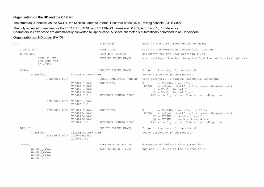
Organization on the HD and the CF Card
The structure is identical on the SX-R4, the MINIR82 and the Internal Recorder of the SX-ST mixing console (STREC82)
The only accepted characters for the PROJET, SCENE and SETTINGS names are: 0 to 9, A to Z and " _ " underscore. Characters in Lower case are automatically converted to Upper-case. A Space character is automatically converted to an Underscore.
Organization on HD drive: (FAT32) E:\ [HDD NAME] name of the disk (free choice of name) CONFIG.DAT [CONFIG.DAT] machine configuration system file (binary)
SETTINGS\ [SETTINGS FOLDER] directory for the User Settings files
USER_01.TXT [SETTING FILES NAME] user settings file (can be edited/modified with a text editor) 4CH_MONO.TXT 8D_48K24 SXR4\ [PROJET FOLDER NAME] Project directory (8 characters)
SCENE001\ [SCENE FOLDER NAME] Scene directory (8 characters)
SCENE001.001\ [SCENE NAME.TAKE NUMBER] Take directory (3 digits, automatic increment)
X00002_1.WAV [BWF FILES] X = SONOSAX identifier X00002_2.WAV 00002 = unique identification number (hexadecimal) X00002_x.WAV _1 = MONO, channel 1 X00002_8.WAV _2 = MONO, channel 2 etc. X00002.INI [RECORDER CONFIG FILE] .INI = configuration file at recording time SCENE001.002\ X00003_x.WAV X00003.INI SCENE001.003\ X0000412.WAV [BWF FILES] X = SONOSAX identifier on CF Card X0000434.WAV 00004 = unique identification number (hexadecimal) X0000456.WAV 12 = STEREO, channels 1 and 2 X0000478.WAV 34 = STEREO, channels 3 and 4 etc. X00004.INI [RECORDER CONFIG FILE] .INI = configuration file at recording time DAY_03\ [PROJET FOLDER NAME] Project directory (8 characters)
SCENE002\ [SCENE FOLDER NAME] Scene directory (8 characters) SCENE002.001\ X00005xx.WAV X00005.INI TRASH\ [TAKE DELETED FOLDER] directory of deleted file (Trash bin)
X00002_1.WAV [TAKE DELETED FILES] BWF and INI files of the deleted Take X00002_x.WAV X00002_8.WAV X00002.INI
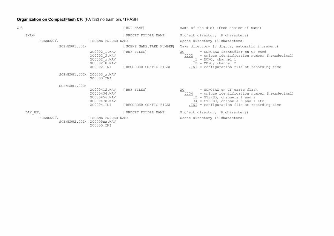
Organization on CompactFlash CF: (FAT32) no trash bin, \TRASH G:\ [HDD NAME] name of the disk (free choice of name) SXR4\ [PROJET FOLDER NAME] Project directory (8 characters)
SCENE001\ [SCENE FOLDER NAME] Scene directory (8 characters)
SCENE001.001\ [SCENE NAME.TAKE NUMBER] Take directory (3 digits, automatic increment)
XC0002_1.WAV [BWF FILES] XC = SONOSAX identifier on CF card XC0002_2.WAV 0002 = unique identification number (hexadecimal) XC0002_x.WAV _1 = MONO, channel 1 XC0002_8.WAV _2 = MONO, channel 2 XC0002.INI [RECORDER CONFIG FILE] .INI = configuration file at recording time SCENE001.002\ XC0003_x.WAV XC0003.INI SCENE001.003\ XC000412.WAV [BWF FILES] XC = SONOSAX on CF carte flash XC000434.WAV 0004 = unique identification number (hexadecimal) XC000456.WAV 12 = STEREO, channels 1 and 2 XC000478.WAV 34 = STEREO, channels 3 and 4 etc. XC0004.INI [RECORDER CONFIG FILE] .INI = configuration file at recording time DAY_03\ [PROJET FOLDER NAME] Project directory (8 characters)
SCENE002\ [SCENE FOLDER NAME] Scene directory (8 characters) SCENE002.001\ X00005xx.WAV X00005.INI
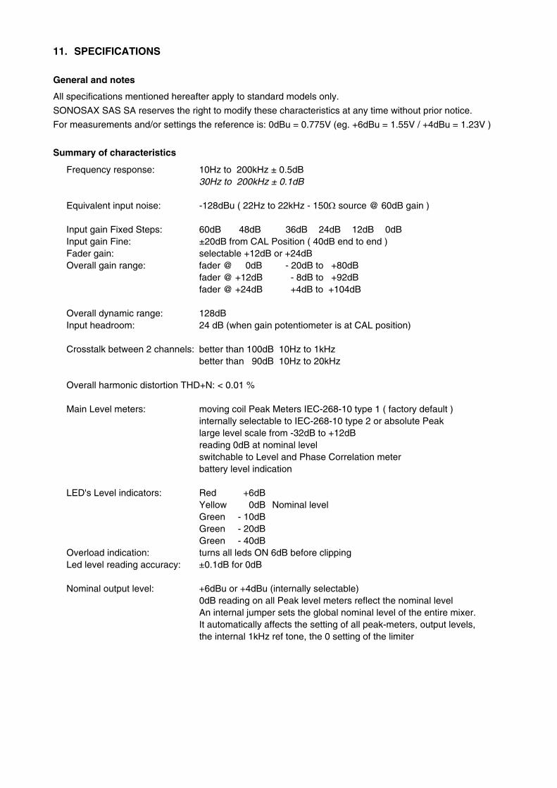
11. SPECIFICATIONS
General and notes
All specifications mentioned hereafter apply to standard models only.
SONOSAX SAS SA reserves the right to modify these characteristics at any time without prior notice.
For measurements and/or settings the reference is: 0dBu = 0.775V (eg. +6dBu = 1.55V / +4dBu = 1.23V )
Summary of characteristics
Frequency response: 10Hz to 200kHz ± 0.5dB 30Hz to 200kHz ± 0.1dB Equivalent input noise: -128dBu ( 22Hz to 22kHz - 150Ω source @ 60dB gain ) Input gain Fixed Steps: 60dB 48dB 36dB 24dB 12dB 0dB Input gain Fine: ±20dB from CAL Position ( 40dB end to end ) Fader gain: selectable +12dB or +24dB Overall gain range: fader @ 0dB - 20dB to +80dB fader @ +12dB - 8dB to +92dB fader @ +24dB +4dB to +104dB Overall dynamic range: 128dB Input headroom: 24 dB (when gain potentiometer is at CAL position) Crosstalk between 2 channels: better than 100dB 10Hz to 1kHz better than 90dB 10Hz to 20kHz Overall harmonic distortion THD+N: < 0.01 % Main Level meters: moving coil Peak Meters IEC-268-10 type 1 ( factory default ) internally selectable to IEC-268-10 type 2 or absolute Peak large level scale from -32dB to +12dB reading 0dB at nominal level switchable to Level and Phase Correlation meter battery level indication LED's Level indicators: Red +6dB Yellow 0dB Nominal level Green - 10dB Green - 20dB Green - 40dB Overload indication: turns all leds ON 6dB before clipping Led level reading accuracy: ±0.1dB for 0dB Nominal output level: +6dBu or +4dBu (internally selectable) 0dB reading on all Peak level meters reflect the nominal level An internal jumper sets the global nominal level of the entire mixer. It automatically affects the setting of all peak-meters, output levels, the internal 1kHz ref tone, the 0 setting of the limiter
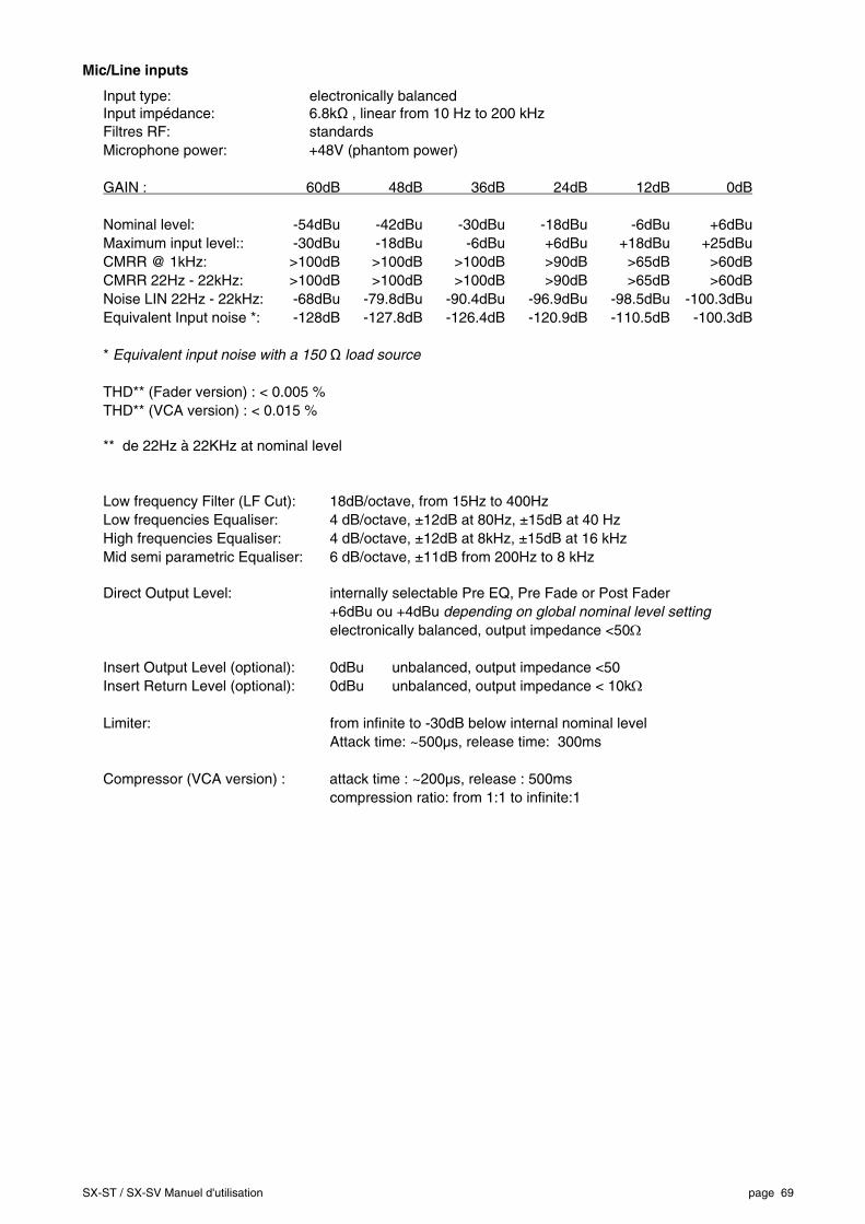
SX-ST / SX-SV Manuel d'utilisation page 69
Mic/Line inputs
Input type: electronically balanced Input impédance: 6.8kΩ , linear from 10 Hz to 200 kHz Filtres RF: standards Microphone power: +48V (phantom power) GAIN : 60dB 48dB 36dB 24dB 12dB 0dB
Nominal level: -54dBu -42dBu -30dBu -18dBu -6dBu +6dBu Maximum input level:: -30dBu -18dBu -6dBu +6dBu +18dBu +25dBu CMRR @ 1kHz: >100dB >100dB >100dB >90dB >65dB >60dB CMRR 22Hz - 22kHz: >100dB >100dB >100dB >90dB >65dB >60dB Noise LIN 22Hz - 22kHz: -68dBu -79.8dBu -90.4dBu -96.9dBu -98.5dBu -100.3dBu Equivalent Input noise *: -128dB -127.8dB -126.4dB -120.9dB -110.5dB -100.3dB * Equivalent input noise with a 150 Ω load source THD** (Fader version) : < 0.005 % THD** (VCA version) : < 0.015 % ** de 22Hz à 22KHz at nominal level Low frequency Filter (LF Cut): 18dB/octave, from 15Hz to 400Hz Low frequencies Equaliser: 4 dB/octave, ±12dB at 80Hz, ±15dB at 40 Hz High frequencies Equaliser: 4 dB/octave, ±12dB at 8kHz, ±15dB at 16 kHz Mid semi parametric Equaliser: 6 dB/octave, ±11dB from 200Hz to 8 kHz Direct Output Level: internally selectable Pre EQ, Pre Fade or Post Fader +6dBu ou +4dBu depending on global nominal level setting electronically balanced, output impedance <50Ω Insert Output Level (optional): 0dBu unbalanced, output impedance <50 Insert Return Level (optional): 0dBu unbalanced, output impedance < 10kΩ Limiter: from infinite to -30dB below internal nominal level Attack time: ~500µs, release time: 300ms Compressor (VCA version) : attack time : ~200µs, release : 500ms compression ratio: from 1:1 to infinite:1
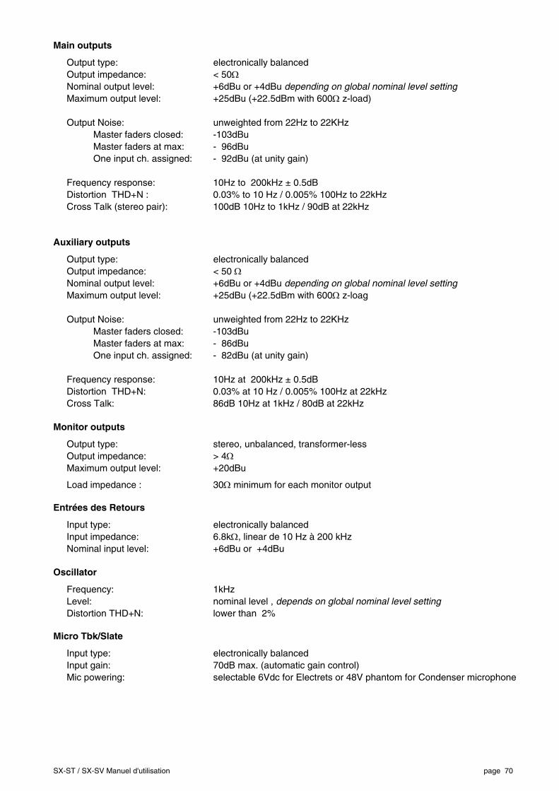
SX-ST / SX-SV Manuel d'utilisation page 70
Main outputs
Output type: electronically balanced Output impedance: < 50Ω Nominal output level: +6dBu or +4dBu depending on global nominal level setting Maximum output level: +25dBu (+22.5dBm with 600Ω z-load) Output Noise: unweighted from 22Hz to 22KHz Master faders closed: -103dBu Master faders at max: - 96dBu One input ch. assigned: - 92dBu (at unity gain) Frequency response: 10Hz to 200kHz ± 0.5dB Distortion THD+N : 0.03% to 10 Hz / 0.005% 100Hz to 22kHz Cross Talk (stereo pair): 100dB 10Hz to 1kHz / 90dB at 22kHz
Auxiliary outputs
Output type: electronically balanced Output impedance: < 50 Ω Nominal output level: +6dBu or +4dBu depending on global nominal level setting Maximum output level: +25dBu (+22.5dBm with 600Ω z-loag Output Noise: unweighted from 22Hz to 22KHz Master faders closed: -103dBu Master faders at max: - 86dBu One input ch. assigned: - 82dBu (at unity gain) Frequency response: 10Hz at 200kHz ± 0.5dB Distortion THD+N: 0.03% at 10 Hz / 0.005% 100Hz at 22kHz Cross Talk: 86dB 10Hz at 1kHz / 80dB at 22kHz
Monitor outputs
Output type: stereo, unbalanced, transformer-less Output impedance: > 4Ω Maximum output level: +20dBu
Load impedance : 30Ω minimum for each monitor output
Entrées des Retours
Input type: electronically balanced Input impedance: 6.8kΩ, linear de 10 Hz à 200 kHz Nominal input level: +6dBu or +4dBu
Oscillator
Frequency: 1kHz Level: nominal level , depends on global nominal level setting Distortion THD+N: lower than 2%
Micro Tbk/Slate
Input type: electronically balanced Input gain: 70dB max. (automatic gain control) Mic powering: selectable 6Vdc for Electrets or 48V phantom for Condenser microphone
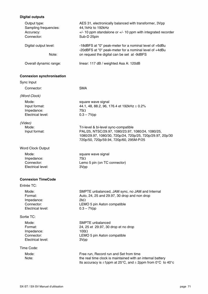
SX-ST / SX-SV Manuel d'utilisation page 71
Digital outputs
Output type: AES 31, electronically balanced with transformer, 3Vpp Sampling frequencies: 44,1kHz to 192kHz Accuracy: +/- 10 ppm standalone or +/- 10 ppm with integrated recorder Connector: Sub-D 25pin Digital output level: -18dBFS at "0" peak-meter for a nominal level of +6dBu -20dBFS at "0" peak-meter for a nominal level of +4dBu Note: on request the digital can be set at -9dBFS Overall dynamic range: linear: 117 dB / weighted Asa A: 120dB
Connexion synchronisation
Sync Input
Connector: SMA
(Word Clock)
Mode: square wave signal Input format: 44.1, 48, 88.2, 96, 176.4 et 192kHz ± 0.2% Impedance: 75Ω Electrical level: 0.3 – 7Vpp (Video) Mode: Tri-level & bi-level sync-compatible Input format: PAL/25, NTSC/29.97, 1080/23.97, 1080/24, 1080/25, 1080/29.97, 1080/30, 720p/24, 720p/25, 720p/29.97, 20p/30 720p/50, 720p/59.94, 720p/60, 295M-P/25 Word Clock Output
Mode: square wave signal Impedance: 75Ω Connector: Lemo 5 pin (on TC connector) Electrical level: 3Vpp Connexion TimeCode
Entrée TC:
Mode: SMPTE unbalanced, JAM sync, no JAM and Internal Format: Auto, 24, 25 and 29.97, 30 drop and non drop Impedance: 2kΩ Connector: LEMO 5 pin Aaton compatible Electrical level: 0.3 – 7Vpp Sortie TC:
Mode: SMPTE unbalanced Format: 24, 25 et 29.97, 30 drop et no drop Impedance: 100Ω Connector: LEMO 5 pin Aaton compatible Electrical level: 3Vpp Time Code:
Mode: Free run, Record run and Set from time Note: the real time clock is maintained with an internal battery Its accuracy is ±1ppm at 25°C, and ± 2ppm from 0°C to 40°c
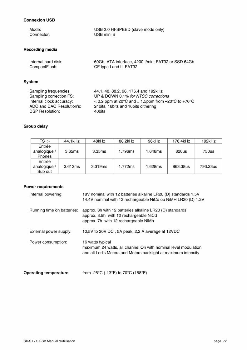
SX-ST / SX-SV Manuel d'utilisation page 72
Connexion USB
Mode: USB 2.0 HI-SPEED (slave mode only) Connector: USB mini B Recording media
Internal hard disk: 60Gb, ATA interface, 4200 t/min, FAT32 or SSD 64Gb CompactFlash: CF type I and II, FAT32 System
Sampling frequencies: 44.1, 48, 88.2, 96, 176.4 and 192kHz Sampling correction FS: UP & DOWN 0.1% for NTSC corrections Internal clock accuracy: < 0.2 ppm at 20°C and ± 1.5ppm from –20°C to +70°C ADC and DAC Resolution's: 24bits, 16bits and 16bits dithering DSP Resolution: 40bits Group delay
FS=> 44.1kHz 48kHz 88.2kHz 96kHz 176.4kHz 192kHz Entrée
analogique / Phones
3.65ms 3.35ms 1.796ms 1.648ms 820us 750us
Entrée analogique /
Sub out 3.612ms 3.319ms 1.772ms 1.628ms 863.38us 793.23us
Power requirements
Internal powering: 18V nominal with 12 batteries alkaline LR20 (D) standards 1,5V 14.4V nominal with 12 rechargeable NiCd ou NiMH LR20 (D) 1.2V Running time on batteries: approx. 3h with 12 batteries alkaline LR20 (D) standards approx. 3.5h with 12 rechargeable NiCd approx. 7h with 12 rechargeable NiMh External power supply: 10,5V to 20V DC , 5A peak, 2,2 A average at 12VDC Power consumption: 16 watts typical maximum 24 watts, all channel On with nominal level modulation and all Led's Meters and Meters backlight at maximum intensity
Operating temperature: from -25°C (-13°F) to 70°C (158°F)
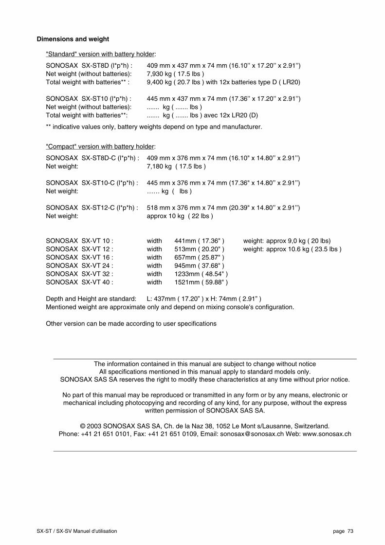
SX-ST / SX-SV Manuel d'utilisation page 73
Dimensions and weight
"Standard" version with battery holder:
SONOSAX SX-ST8D (l*p*h) : 409 mm x 437 mm x 74 mm (16.10’’ x 17.20’’ x 2.91’’) Net weight (without batteries): 7,930 kg ( 17.5 lbs ) Total weight with batteries** : 9,400 kg ( 20.7 lbs ) with 12x batteries type D ( LR20) SONOSAX SX-ST10 (l*p*h) : 445 mm x 437 mm x 74 mm (17.36’’ x 17.20’’ x 2.91’’) Net weight (without batteries): ....... kg ( ....... lbs ) Total weight with batteries**: ....... kg ( ....... lbs ) avec 12x LR20 (D)
** indicative values only, battery weights depend on type and manufacturer.
"Compact" version with battery holder:
SONOSAX SX-ST8D-C (l*p*h) : 409 mm x 376 mm x 74 mm (16.10" x 14.80’’ x 2.91’’) Net weight: 7,180 kg ( 17.5 lbs ) SONOSAX SX-ST10-C (l*p*h) : 445 mm x 376 mm x 74 mm (17.36" x 14.80’’ x 2.91’’) Net weight: …… kg ( lbs ) SONOSAX SX-ST12-C (l*p*h) : 518 mm x 376 mm x 74 mm (20.39" x 14.80’’ x 2.91’’) Net weight: approx 10 kg ( 22 lbs ) SONOSAX SX-VT 10 : width 441mm ( 17.36" ) weight: approx 9,0 kg ( 20 lbs) SONOSAX SX-VT 12 : width 513mm ( 20.20" ) weight: approx 10.6 kg ( 23.5 lbs ) SONOSAX SX-VT 16 : width 657mm ( 25.87" ) SONOSAX SX-VT 24 : width 945mm ( 37.68" ) SONOSAX SX-VT 32 : width 1233mm ( 48.54" ) SONOSAX SX-VT 40 : width 1521mm ( 59.88" ) Depth and Height are standard: L: 437mm ( 17.20” ) x H: 74mm ( 2.91” ) Mentioned weight are approximate only and depend on mixing console's configuration. Other version can be made according to user specifications
The information contained in this manual are subject to change without notice All specifications mentioned in this manual apply to standard models only.
SONOSAX SAS SA reserves the right to modify these characteristics at any time without prior notice.
No part of this manual may be reproduced or transmitted in any form or by any means, electronic or mechanical including photocopying and recording of any kind, for any purpose, without the express
written permission of SONOSAX SAS SA.
© 2003 SONOSAX SAS SA, Ch. de la Naz 38, 1052 Le Mont s/Lausanne, Switzerland. Phone: +41 21 651 0101, Fax: +41 21 651 0109, Email: [email protected] Web: www.sonosax.ch