sop 6-2 sonde deployment - env.nm.gov · described in the swqb 's sonde calibration and...
TRANSCRIPT

Effective Date: 3/13/2018
No: SOP-6.2 1 Page 1 of 16 ~ Revision 5 _L_
Title: Sonde Deployment
Next Revision Date: 3/13/2020 _ _
New Mexico Environment Department (NMED) Surface Water Quality Bureau (SWQB)
Standard Operating Procedure (SOP) for
SONDE DEPLOYMENT
?
Subject Matter Expert
Quality Assurance Officer
Program Manager - Monitoring, Assessment and Standards Section
~I Date
~~l~ /lR

Title: Sonde Deployment No: SOP 6.2 l Pa9e 2 of 16-Revision 5 t_
Effective Date: 3/13/2018 Next Revision Date: 3/13/2020 ~~----------------------~~ -~------~
1.0 Purpose and Scope
The purpose of this document is to describe the Surface Water Quality Bureau's (SWQB's) procedure for deploying water quality monitoring sondes and dataloggers (excluding thermographs) in rivers and streams for instantaneous or unattended measurements. This procedure covers use of YSI 6-Series Sondes, Hydrolab MS5 Sondes, Onset HOBO Dissolved Oxygen (DO) dataloggers, Onset HOBO Conductivity dataloggers, and In-Situ Aqua TROLL 600 Multiparameter Sondes described in the SWQB 's Sonde Calibration and Maintenance Standard Operating Procedures (SOP) (SOP 6.1).
2.0 Personnel Responsibilities
All personnel who operate or deploy sondes and dataloggers are responsible for implementing this procedure and shall acknowledge such by signing the SOP 6.2 Sonde Deployment Acknowledgement Page.
One individual within SWQB is designated as the "Sonde Manager." A second individual is designated as the "Alternate Sonde Manager" who fulfills the manager's responsibilities when the manager is unavailable. The Sonde Manager or Alternate Sonde Manager is responsible for:
• ensuring sondes are properly maintained and stored; • maintaining the" Sonde Tracker" spreadsheet; • maintaining electronic data files on NMED's internal server under "MASS"; • maintaining calibration sheets in binders stored in the laboratory in order to avoid confusion
and/or misplacement of data; and, • training field personnel, as needed, so they are capable of operating sondes, including
calibration, post-deployment checking, and data recording
The Long-term Deployment (LTD) Coordinator and/or the Project Manager are responsible for managing unattended sampling data, in accordance with the SWQB's Long Term Deployment Data Logger (Thermographs and Sondes) Data Quality Assurance and Surface Water Quality Information Database (SQUID) Upload Instructions (SOP 6.4), and for assisting the Sonde Manager with tracking the location and status of sondes.
Field Staff are responsible for: • coordinating with the Sonde Manager or Alternate Sonde Manager on the scope of the
project and use of the equipment; • investigating calibration and calibration verification failures and reporting equipment
malfunction to the Sonde Manager or Alternate Sonde Manager. • transferring sonde data off the instrument following long-term deployment in accordance
with SWQB's Data Logger and Upload SOP (SOP 6.4); • quality assurance (QA) ofsonde/datalogger data in accordance with the SWQB's Data
Verification and Validation SOP (SOP 15.0); and, • filing calibration sheets in binders stored in the laboratory and filing long-term
deployment/calibration/post check sheets and sampling run post-checks in the project binder.

Effective Date: 3/13/2018 1 No: SOP 6.2 I Page 3 of 16 Revisio"ii"S I
------~~--------~ Next Revision Date: 3/13/2020 -------
Title: Sonde Deployment
3.0 Background and Precautions
3.1 Background
This procedure is based on the capabilities of the In-Situ, YSI, and Hydrolab sondes and sensors and Onset HOBO® Dissolved Oxygen (DO) dataloggers and Onset HOBO® Conductivity dataloggers described in Section 5.0.
3.2 Procedural Precautions
Individuals using a sonde or datalogger should have a thorough understanding of its proper use and care and be familiar with the instrument's operational manual and this SOP in order to ensure data is not invalidated due to calibration or user error.
3.3 Safety Precautions
3.3.1 Streambed Dangers and Obstacles
Some channels have quicksand-like areas, deep holes, sharp rocks, fallen logs, etc., that can cause foot entrapment, injury, or falls. In areas with either unstable or unknown substrate stability, a walking stick or other suitable probing device (such as a wading rod without the current meter attached) can be used for stabilization and to probe the streambed. General field work awareness and protocol should be implemented at each location prior to commencement of field work.
3.3.2 T-Post and Rebar Precautions
Sondes are frequently deployed mounted toT-posts or rebar driven into the stream substrate. A void driving any material into the stream bottom or banks near bridges or where underground utilities are suspected. If there is any question of whether underground utilities are present at the monitoring location, call "811" or visit www .nm811.org to schedule a utility location. Rebar and T -posts present trip and impalement hazards. Exercise caution when working around driven rebar and T-posts. Do not install rebar or T-posts in areas used for recreation or adjacent to trails or stream crossings. A void mid-channel placements in waters with boat traffic. For rebar, place a protective cap on the end to prevent accidental impalement. Removal of rebar and T -posts involves the use of anything from hand tools to mechanical jacks. Mechanical jacks can be extremely dangerous under load, especially with unstable support. Operate the jack only after instruction by experienced personnel and with assistance. Consider placement, footing, and strike/slip danger.
3.3.3 Rule ofTen
Wading across a streambed can be dangerous depending on flow and substrate conditions. Do not attempt to wade into a stream if the depth (in feet) multiplied by the velocity (in feet/second) equals or exceeds ten (10). For example, a stream two (2) feet deep and with a

Title: Sonde Deployment No: SOP 6.2 I Page 4 of 16 Revision 5 I
Effective Date: 3/13/2018 Next Revision Date: 3/13/2020
velocity of five (5) feet/second or more should be considered too dangerous to wade. If you start to take measurements and discover part of the way across a stream that you are violating or will violate the "rule often", return to the nearest bank and note "too fast/deep to measure" on the field form.
4.0 Definitions
Program Manager- An individual within the SWQB that manages a program such as the Watershed Protection Section (WPS), the Point Source Regulation Section (PSRS) or the Monitoring, Assessment and Standards Section (MASS). The Program Manager and Project Manager are not necessarily synonymous.
Project Manager- An individual responsible for a specific project. This individual, in most cases, holds a different title within the organization. The Program Manager and Project Manager are not necessarily synonymous. The Project Manager may be the same individual as the Subject Matter Expert.
Quality Assurance Officer (QAO)- An individual within the MASS that is responsible for overseeing the development and implementation of all quality assurance procedures and processes within the SWQB including those projects that receive support or funding from the SWQB. The QAO is also responsible for validating and verifying data sets for potential use in assessment of surface waters.
Standard Operating Procedure (SOP)- A document that lists the steps that should be completed when doing a task.
Subject Matter Expert (SME) -A person who is familiar with the purpose and procedure for accomplishing a task. The SME may be the same individual as the Project Manager.
Surface Water Quality Bureau (SWQB)- A Bureau under the Water Protection Division of the New Mexico Environment Department. The SWQB's mission is to preserve, protect, and improve New Mexico's surface water quality for present and future generations.
Datalogger - a water quality monitoring device that measures one or more parameters and can be deployed for unattended monitoring.
Onset HOBO Conductivity Logger - a water quality monitoring device that measures and records conductivity and temperature that is deployed for unattended monitoring.
Onset HOBO Dissolved Oxygen Logger (DO datalogger)- a water quality monitoring device that measures and records dissolved oxygen and temperature that is deployed for unattended monitoring.
Sonde - a submersible device used to measure multiple water quality parameters. Note: the term "sonde" is used in this document to describe YSI, Hydrolab, and In-Situ Sondes and Onset HOBO DO Loggers and Conductivity Loggers.
Handset - a device used to display information from a sonde or datalogger

Title: Sonde Deployment No:SOP6.2 I Page 5 of 16 Revision 5 I
Effective Date: 3/13/2018 Next Revision Date: 3/13/2020
Centroid- the midpoint of the portion of the stream width that contains approximately 50 percent of the total flow.
Deployment - use of a sonde at a monitoring location to perform and record measurements of water quality.
Long-term Deployment - deployment of a sonde for unattended monitoring at repeated discrete intervals.
Instantaneous measurement - An instrument reading collected manually at a single point in time. Synonymous with grab or instantaneous measurements.
Field parameter - individual characteristic of water quality capable of being measured by a sonde or datalogger. Typical field parameters include pH, dissolved oxygen saturation and concentration, specific conductance, turbidity, and temperature.
5.0 Equipment and Tools
5.1 Sonde specifications
The primary field instruments employed by SWQB are manufactured by YSI, Inc., Ott Hydromet (formerly Hach Environmental), Onset Computer Corporation and In-Situ, Inc.
YSI, Inc. 1700 Brannum Lane, Yellow Springs, OH 45387 Phone: (937) 688-4522 or (877) 726-0975, Fax: (937) 767-9353 Email: [email protected] Internet: www.ysi.com
Ott Hydromet 5600 Lindbergh Dr., Loveland, CO 80539 Phone: (800) 949-3766 Email: techsuggort@otthydromet Internet: www.hydrolab.com
Onset Computer Corporation 470 MacArthur Blvd, Bourne, MA 02532 Phone: (800) 564-4377, Fax: (508) 759-9500 Email: [email protected] Internet: www.onsetcomg.com
In-Situ, Inc. 221 E. Lincoln Ave., Fort Collins, CO 80524 Phone: (800) 446-7488 Email: [email protected] Internet: www.in-situ.com
The specific YSI sonde model numbers are 6820, 6920, 600XLM, 6000MS and 650 MDS data loggers. All use EcoWatch or EcoWatch Lite software, a proprietary product ofYSI, Inc. (see YSI
Title: Sonde Deployment No: SOP 6.2 T -fiage 6 of 16 Revision 5 _C
Effective Date-: -::3:-:-/1:-:3::-7/2=:0:-:1:-::8,-----------------t---;N'""e.:....x--:'t";;;R:-e-o-vision Date: 3/13/2020
website for current versions). Sonde models 6920 and 6000MS can be programmed for unattended data collection.
The specific Hydrolab sonde model number is MS5, which uses Hydras 3LT software to interface with PCs. This software is a proprietary product of Hach Company.
The specific In-Situ model number is Aqua TROLL 600. This instrument can either be used with In-Situ's proprietary software, Win-Situ, for communication with PCs or a mobile app, View-Situ, for communication with tablets and mobile devices.
The specific Onset devices are the HOBO DO Logger model U26-001 and Conductivity Logger model U24-001, which both use the proprietary software HOBOware to communicate with a PC.
Sondes and sensors are described in Table 1. Instruction manuals for the sondes and sensors are available in the lab and on the SWQB file server. The following procedures are based largely on information in these manuals.

Title: Sonde Deployment No: SOP 6.2 I Page 7 of 16 Revision 5 I
Effective Date: 3/13/2018 Next Revision Date: 3/13/2020
Table 1
Sonde and Sensor Characteristics
Sensor Parameter Units Range Accuracy
YSI 6560 Temperature oc -5 to +50 ± 0.15 oc 6560 Conductivity J.LS/cm 0 - ± 0.5% of reading; ± 1
100,000 J:!Sicm 6562 Dissolved % 0 - 500 ±2%
Oxygen saturation 6150 (Optical) Dissolved % 0-500 ± 1%
Oxygen saturation 6562 Dissolved mg/L 0-50 0 to 20 mg/L: ± 0.1 mg/L
Oxygen or 1% of reading, whichever is greater; 20 to 50 mg/L: ± 15% of readin
6150 (Optical) Dissolved mg/L 0-50 0 to 20 mg/L: ± 0.2 mg/L Oxygen or 2% of reading,
whichever is greater; 20 to 50 mg/L: ±6% of reading
6561 pH su 0 - 14 ± 0.2 su 6026 or 6136 Turbidity NTU 0 - 1000 ±2%
H1;:drolab
MS5 Thermistor Temperature oc -5 to +50 ± 0.10 oc 004468 Conductivity J.LS/cm 0 - ± 1% of reading; ± 1
100,000 J:!Sicm 007455 Dissolved % 0 - 500 ± 1%
Oxygen saturation 007455 Dissolved mg/L 0 - 60 ± 0.1 mg/L for 0-8 mg/L;
Oxygen ± 0.2 mg/L for greater than 8 mg/L
004446 pH su 0 - 14 ± 0.2 su 007140 Turbidity NTU 0 - 3000 ± 1% up to 100 NTU, ±
3% up to 100-400 NTU, ± 5% from 400-3000 NTU
Onset DO Logger
U26-001 Dissolved mg/L 0-30 0.2mg/L up to 8mg/L; 0.5 Oxygen mg/L from 8 to 20mg/L
Thermistor Temperature oc -5 to 40 ± 0.2°C
Onset Conductivitv Logger

Title: Sonde Deployment Revision 5
Effective Date: 3/13/2018 Next Revision Date: 3/13/2020 -------------------------
No: SOP 6.2 l Page 8 o~f6
U24-001
Thermistor
In-Situ 63490
63490
63450
63450
63470
63480
Conductivity
Temperature
Temperature
Conductivity
Dissolved Oxygen Dissolved Oxygen
pH
Turbidity
JlS/cm
JlS/cm
% saturation mg/L
su NTU
0 - 10,000
5 - 35
-5 to +50
0 -200,000
0 - 500
0 - 50
0 - 14
0 - 4000
± 3% of reading; ± 5 S/cm
± 0.1 oc
± 0.10 oc ± 0.5% of reading; ± 1 JlS/cm for 0-100,000, ± 1% of reading> 100,000 ± 1%
± 0.1 mg/L for 0-8 mg/L; ± 0.2 mg/L for greater than 8 mg/L ± 0.1 su ± 2% of reading; ± 2 NTU
5.2 List of equipment required for instantaneous measurement and long-term deployment
• YSI 650 MDS Unit • Onset HOBO® Optical Shuttle • Onset HOBO® Base Station • Sensor Guard/Restrictor/Cover • Calibration Cup • Pocket PC • Windows Tablet or Laptop Computer • Mobile Device (Android) • Communication port caps • Interface Cable • Nylon Cable Ties • Hose Clamps • Five-gallon Bucket • Field Calibration Standards and Buffers • Spare Batteries (sonde specific: AA, CorD cells) • Steel T -posts (6ft and 8ft) • T-post driver • Steel rebar (2ft, 3ft, 4ft, and 6ft) • Tie wire • Chain/cable and weather-resistant padlock • Diagonal pliers • Lineman's pliers • Pipe wrench (10" and 12") • Mechanical jack, t-post puller, and nylon sling • Modified mattock • Sonde/datalogger cover sleeve - perforated PVC tube of sufficient length to fully contain
equipment • Digital camera

Title: Sonde Deployment No: SOP 6.2 I Page 9 of 16 Revision 5 I
Effective Date: 3/13/2018 Next Revision Date: 3/13/2020
• Global Positioning System (GPS) unit • Barometer • 30 meter measuring tape • Surveyor's flagging tape • Calibration worksheet • Field Data Forms • Field Notebook as applicable • Clipboard
6.0 Step-by-step Process
6.1 Instantaneous Measurement and Long-term Deployment (All Units)
6.1.1 Preparation
Each sensor requires calibration before field use and an accuracy check upon retrieval in accordance with SWQB's Sonde Calibration and Maintenance SOP (SOP 6.1). Calibration of the sensors should be done more frequently ifthere is reason to suspect a problem (e.g., biofouling) in the waterbody being monitored.
Record all calibration and calibration verification data on the Calibration Worksheet prior to and following instantaneous field measurements and unattended deployments, respectively (See Sonde Calibration and Maintenance SOP 6.1). For instantaneous measurements, when calibrating the DO sensor, record the calibration data in the correct location on the Stream Field Data Form.
Ensure sonde battery voltage is sufficient for planned operation. Always bring a full set of fresh batteries for the instrument, handset, etc. in the field.
For long-term deployments with YSI, Hydrolab, or In-Situ sondes, record the calibration and calibration verification data on the Calibration Worksheet provided on the back of the Sonde Deployment/Retrieval Field Sheet. Calibrate the DO sensor in the field to the appropriate elevation.
For deployments with Onset dataloggers, record datalogger information on the appropriate Logger Deployment Form. For the Onset DO datalogger, calibrate DO prior to deployment.
Sondes deployed for unattended sampling are to be inspected monthly (if practicable) and at the end of deployment. Sensors should be calibrated if there is reason to suspect a problem with the sensors or the data. If possible, calibrate the DO sensor in the field at the elevation of the station.
6.1.2 Instantaneous Measurements (All Units)
Note: Onset HOBO dataloggers are not intended for instantaneous measurement.
Measure field parameters during each sampling event as specified in the approved project's Field Sampling Plan, and record the values on the Stream Field Data Form. Use a separate

Title: Sonde Deployment No: SOP 6.2 l_lige 10 of~6 Revision 5 _!=-Next Revision Date: 3/13/2020 Effective Date: 3/13/2018
form for each station. Record all digits as they are displayed on the sonde handset or mobile device. Enter additional comments regarding sampling conditions or equipment status as appropriate. Before leaving the site, review the field form for completeness and accuracy.
In streams and rivers, attempt to take measurements where the stream is flowing and well mixed. A void stirring up sediment when placing the sonde in the water. If the stream is not well mixed, it may be necessary to move to a location that is mixed (up to 500 meters before a new station must be created). A void sampling in backwaters, eddies, and directly below a confluence or discharge.
Figure 1. Example of an unmixed channel directly below a confluence.
At all locations, replace the calibration cup with the sensor guard and carefully place the sonde in the water with the sensors exposed to oncoming current and above bottom sediments. The sonde should be situated vertically in the water column, three (3) to six (6) inches above the substrate. When water depth is too shallow to allow vertical orientation of the sonde, it may be placed horizontally in the water column, with sensors facing upstream and into the flow. Avoid entrapment of air in the sensor chamber, which can be indicated by unstable conductance values fluctuating up to ±100 ~S/cm. Do this by slowly and carefully placing the sonde into the stream and quickly moving it through the water while the sensors are completely submerged, releasing any air bubbles. Allow the sensors to equilibrate for at least one ( 1) minute in "Run" mode, which can be done while water samples are being collected

Title: Sonde Deployment No: SOP 6.2 I Page 11 of 16 Revision 5 I
Effective Date: 3/13/2018 ~ext Revision Date: 3/_13_/_20_2_0 ___ ______,
When instantaneous field parameters cannot be measured due to low flow or a discharge from a pipe, they may be measured in the calibration cup/restrictor or a bucket used for sample collection. Consider building small dams or depressions to create water deep enough to submerge the sensors. Allow suspended sediment to clear before collecting readings with sonde. Use a bucket only when all efforts to obtain measurements directly from the source have been exhausted. A small container can be used to fill the calibration cup/restrictor in very shallow situations. Use a bucket that is large enough to allow full immersion of the sensors and bring the bucket to the same temperature as the water before it is filled. If a bucket is used, make clear notes on the Stream Field Data Form indicating what methods were used to obtain an adequate water sample volume.
Record temperature, conductance, pH, turbidity, and finally, DO on the Stream Field Data Form, or log results using the internal storage of the sonde handset or mobile device and transfer the data from the handset to the Stream Field Data Form prior to leaving the monitoring location. After each sampling trip, transfer the information to the SWQB water quality database and store the Stream Field Data Form in the project binder.
6.1.3 Long-term Deployment (All Units)
6.1.3.1 Site Selection and Installation
Find a discrete location in a representative portion of the stream reach, where the sonde is not easily detectable and immediate upstream of anthropogenic disturbances where they are not likely to effect ambient water quality conditions. Ensure unattended sondes deployed for monitoring are securely anchored and protected. Installation methods include:
• mounting to a T -post using pipe clamps • mounting to rebar using pipe clamps or zip ties • suspending from fence posts, bridges, or other stable overhanging objects
using steel cable • attaching to existing monitoring station structures (gages, bridge pilings,
etc.) • tree roots at least arm-thickness in diameter using zip ties
The sonde should be deployed vertically where the sensors are most likely to remain submerged in representative flow. The deployment location should consider factors such as the risk of debris accumulation, channel scour or burial, and vandalism or theft. If the sonde cannot be placed vertically it may be mounted horizontally three (3) to six (6) inches above the substrate (to allow sufficient space for sediment and bedload transport) with the sensor guard pointed upstream and secured to a stable object such as rebar or a T -post. A void having the sonde and its sensors directly contact substrate in either the vertical or horizontal position. In stable streams where the substrate is primarily bedrock, boulder, or cobble the sonde may be placed on the stream bottom if no other options exist. !fusing a cover sleeve, place the sonde with sensor guard in the cover sleeve (note this in the comment field on the sonde or logger deployment/retrieval form), which is perforated to allow the flow to contact the sensors while protecting the sonde from debris. Keep in mind that, while the cover sleeve may protect the sonde, it may also trap sediment in turbid waters and
Title: Sonde Deployment
Effective Date: 3/13/2018 --~~------------------
No: SOP 6.2 J Page 12~f 16 Revision 5 Next Revision Date: 3/13/2020
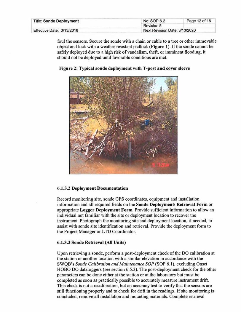
foul the sensors. Secure the sonde with a chain or cable to a tree or other immovable object and lock with a weather resistant padlock (Figure 1). If the sonde cannot be safely deployed due to a high risk of vandalism, theft, or imminent flooding, it should not be deployed until favorable conditions are met.
Figure 2: Typical sonde deployment with T-post and cover sleeve
6.1.3.2 Deployment Documentation
Record monitoring site, sonde GPS coordinates, equipment and installation information and all required fields on the Sonde Deployment/ Retrieval Form or appropriate Logger Deployment Form. Provide sufficient information to allow an individual not familiar with the site or deployment location to recover the instrument. Photograph the monitoring site and deployment location, if needed, to assist with sonde site identification and retrieval. Provide the deployment form to the Project Manager or LTD Coordinator.
6.1.3.3 Sonde Retrieval (All Units)
Upon retrieving a sonde, perform a post-deployment check of the DO calibration at the station or another location with a similar elevation in accordance with the SWQB's Sonde Calibration and Maintenance SOP (SOP 6.1), excluding Onset HOBO DO dataloggers (see section 6.5.3). The post-deployment check for the other parameters can be done either at the station or at the laboratory but must be completed as soon as practically possible to accurately measure instrument drift. This check is not a recalibration, but an accuracy test to verify that the sensors are still functioning properly and to check for drift in the readings. If site monitoring is concluded, remove all installation and mounting materials. Complete retrieval

[
Title: Sonde Deployment No: SOP 6.2 I Page 13 of 16
-=-=cc----=--:-----=-=--:-::-:-=--=--c---=---------------t-,--Revision 5 -=---:c-.,.-JIL:-:-:::-=-=-=-------l Effective Date: 3/13/2018 Next Revision Date: 3/13/2020 ~~~~~~~~-------------'~
information on the Sonde Deployment Form or appropriate Logger Deployment Form. Provide the completed deployment form to the Project Manager or LTD Coordinator.
Retrieve deployment data from the sonde and copy to the project file location on a secure server. Do not delete data files from the sonde until archiving and back-up are complete. The Project Manager or LTD Coordinator are responsible for uploading the data to the database following procedures specified in SOP 6.4 Datalogger (Thermograph and Sonde) Data Management, Quality Assurance and Upload Instructions. Return sondes to the sonde storage area. Document equipment problems and report to the Sonde Manager, LTD Coordinator or Project Manager.
6.2 YSI Sonde: Instantaneous Measurement and Long-term Deployment
Refer to section 6.1 Instantaneous Measurement and Long-term Deployment (All Units)
6.2.1 Preparation (YSI Sonde)
Follow instructions indicated for all units in Section 6.1.1.
6.2.2 Instantaneous Measurement: Monitoring and Recording (YSI Sonde)
A. Connect the sonde to a cable and handset. B. Remove the calibration cup and install a sensor guard. C. Tum on the handset and select sonde run. D. After the sonde has stabilized, after approximately 1 minute, record measurements on
the Stream Field Data Form. Note: It may be necessary to clean the sensors if the sonde will not stabilize for DO or turbidity. At the top of the run screen arrow over to the clean optics and select.
E. After the measurements have recorded power the sonde off, remove the sensor guard, and install the calibration cup.
6.2.3 Sonde Long-term Deployment (YSI Sonde)
Note: For a sonde with a Rapid Pulse DO sensor, you must allow 15 minutes of"Run" time after changing the DO membrane to allow the membrane to "bum-in". After "bumin", at least 6 hours is required for the membrane to stabilize prior to the pre-deployment calibration. If this is not practicable, use a sonde with an optical DO sensor. The steps listed below outline the programming commands for the 650 YSI Data Logger:
A. Connect the sonde to a cable and 650 MDS handset. B. Tum the handset power on and follow the setup instructions below: C. Verify correct time and update, if needed
Sonde Menu - System - Date & Time - Date/Time D. Disable "Power Sonde" in 650 MDS settings
650 Main Menu - System Setup - Power Sonde (unchecked) E. Enable "wait for DO"- Rapid Pulse DO sensors only
Sonde Menu- Advanced- Sensor- Wait for DO (checked)

j Title: Sonde Deployment
I Effective Date:- 3"""""'/1- 3"""""'/2-=-o=-1.....,8 ______ _
No: SOP 6.2 I Page 14 of 19 Revision 5 . Next Revision Date: 3/13/2020
------~
F. Enable "auto sleep" Sonde Menu ~ Advanced ~ Setup ~ Enable Auto Sleep RS232 (checked)
G. DO warm-up time (RP membrane only) should not be decreased; it may be increased to yield better results. Contact the Project Manager or LTD Coordinator before adjusting the DO warm-up time.
H. Enable recording of field parameters Sonde Menu~ Sensor~ Check: Time, Temperature, Conductivity, ISEl pH, Optic-T Turbidity 6136, Optic-C 6150 ROX Optical DO, Battery (Note: Dissolved Oxy is the 6562 Rapid Pulse membrane sensor. Do not check unless not using the Optical DO sensor.)
I. Initiate Recording/Run Unattended Sample Sonde Menu ~ Run ~ Unattended sample • Set interval (15 minutes is preferred, but should not be greater than 1 hour), start
date, start time, duration • Create file name (mandatory), site (optional) • Verify battery life and memory are sufficient for deployment length • Verify collected field parameters by selecting "View params to log" • Scroll to "Start logging" and press enter key ~ Start Logging • "Are you sure?" Enter "yes"
J. Verify Logging Status Sonde Menu ~ Status
K. Detach cable and install pressure cap. Remove the calibration cup and install the sensor guard.
L. Install the sonde at the monitoring location. See Section 6.1.3.1 Site Selection and Installation
6.2.4 Sonde Retrieval (YSI Sonde)
A. Remove the sonde from the waterbody. B. Remove the sensor guard and install the calibration cup. C. Connect the sonde to a cable and 650 MDS handset. D. Turn on handset. E. Stop Logging
Sonde Menu ~ Run ~ Unattended sample ~ Stop logging ~ Yes F. Follow YSI Sonde Data Upload Instructions from 6.4 Datalogger (Thermograph and
Sonde) Data Management, Quality Assurance and Upload Instructions SOP.
6.3 Hydrolab Sonde: Instantaneous Measurement and Long-term Deployment
Refer to section 6.1 Instantaneous Measurement and Long-term Deployment (All Units)
6.3.1 Preparation (Hydrolab Sonde)
Follow instructions indicated for all units in Section 6.1.1.
6.3.2 Instantaneous Measurement: Monitoring and Recording (Hydrolab Sonde)
A. Connect the sonde to a cable and PDNWindows Mobile Device.

r No- : -SO-P-6:2 - ~- Page 15 of 16 Revision 5
Title: Sonde Deployment
Next Revision Date: 3::-:/1-:'-:3:-:-/2::-:0:-::2-::-0----1 Effective Date: 3/13/2018 ----------B. Remove the calibration cup and install a sensor guard. C. Select Hydras 3 Pocket for Hydro lab. D. Initiate data collection
Connect ---+ monitoring ---+ time series ---+ start ---+ current values E. After the sonde has stabilized, after approximately 1 minute, record measurements on
the Stream Field Data Form. F. After the measurements have been recorded exit back to the main menu and select
disconnect. Power the PDA off, remove the sensor guard, and install the calibration cup.
6.3.3 Sonde Long-term Deployment (Hydrolab Sonde)
6.3.3.1 Creating Log Files using a PC
Note: A log file must be created and then enabled before data can be collected. A. Connect the Data Cable to a computer and to the sonde. B. Start Hydras 3 LT. The software will automatically scan for sondes. All
detected sondes are displayed in the 'Connected Sondes' list in the Main window displayed below. If a sonde is not found, reattach the data cable and press RE-SCAN FOR SONDES. Retry until the sonde is found.
C. Click on the Log Files tab. D. Click the CREATE button. E. Enter the name for the new log file. The empty log file is now created. F. Enter the start and end time of the logging, the logging interval (15 minutes
is preferred, but should not be greater than 1 hour), the sensor warm-up time before logging (20 seconds is sufficient), and how long before logging the circulator will be turned on (20 seconds), and if audio signals will be used while logging.
G. Select the parameters in the 'Parameter in Sonde' list and click the ADD button to place them into the 'Parameters in log file' list. Change the order of the parameters using the ARROW buttons.
H. Click UPDATE SETTING to send the configuration to the sonde. I. Click ENABLE to start collecting data. Click DISABLE to stop collecting
data during logging. A fully completed logging run will automatically disable at the end of the run.
J. Click DOWNLOAD to download and display the log file. Select printable or spreadsheet format, and save the file to your chosen location.
Note: To delete a log file, select the logfile in the Log File drop-down menu and click the DELETE button.
6.3.3.2 Setting up the Hydrolab for data logging using the PDA/Windows Mobile Device
Creating a new log file: A. Select LOG FILES from the main screen. The Log Files screen will be
displayed. B. Select NEW. C. Enter the name of the new log file and select OK. The Log File Setup screen
will be displayed.

Title: Sonde Deployment No:SOP6.2 Page 16 of 16 Revision 5
Effective Date: 3/13/2018 Next Revision Date: 3/13/2020--
D. Select the General tab. Enter the setup information for the log file as follows: • Start: date and time when the log file will begin collecting data. • End: date and time when the log file will stop collecting data. • Interval: time interval (HH:MM:SS) between data points • Sensor Warm-up: Set to 20 seconds• Circulator: Set to 20 seconds • Audio: sound made when measurements are taking place.
E. Select the Parameters tab. Add the parameters to include in the log file by selecting the check box next to each parameter. Change the order by highlighting the parameter and selecting UP or DOWN to move the parameter. Use the scroll bar to scroll up or down.
F. Select SAVE SETTINGS to save the log file settings. G. Select Templates in the lower left comer to save the log file settings in the
PDA for use in multiple sondes. Enter a name for the template and select OK. When setting up a new log file in a different sonde, select Templates>Load to populate the setup fields. Note: The new log file will not log data until it is activated.
Activating a log file <IMPORT ANT> A. Select LOG FILES from the main screen. The Log Files screen will be
displayed. B. Highlight the log file to activate and select TO ENABLE.
The status will change from Disabled to Enabled. The sonde will begin recording data in the new log file at the specified start time. Important Note: Log files that have completed running cannot be activated for re-use by changing the date. For log files occurring in the future, always set up a new log file.
After log files have been created. Detach the cable and install the protective cap. Remove the calibration cup and install the sensor guard. Install the sonde at the monitoring location. See Section 6.1.3.1 Site Selection and Installation
6.3.4 Sonde Retrieval (Hydrolab Sonde)
A. Remove the sonde from the stream. B. Remove the sensor guard and install the calibration cup. C. Follow Hydrolab Sonde Data Upload Instructions from SOP 6.4 Datalogger
(Thermograph and Sonde) Data Management, Quality Assurance and Upload Instructions.
6.4 In-Situ Sonde: Instantaneous Measurement and Long-term Deployment
Refer to section 6.1 Instantaneous Measurements and Long-term Deployment (All Units)
6.4.1 Preparation (In-Situ Sonde)
Follow instructions indicated for all units in Section 6.1.1.
6.4.2 Instantaneous Measurement: Monitoring and Recording (In-Situ Sonde)

I Title: Sonde Deployment
I Effective Date: 3/13/2018 -----
A. Activate Bluetooth on mobile device. B. Open the VuSitu App and connect to the sonde.
Revision 5 I · l No: SOP 6.2 - JPage 17 of 16
Next Revision Da-:t-e:-:3:-:-/1-:'-.:3:-:-/2:::-:0'""2-=-o----1
C. Hold the sonde upside down (sensors pointed up) for three seconds to tum it on. D. Remove the restrictor and place it sampling mode. E. Select live readings. F. After the sonde has stabilized, after approximately 1 minute, record measurements on
the Stream Field Data Form. G. After the measurements have been recorded disconnect the Bluetooth connection and
remove the restrictor and reinstall in storage mode.
6.4.3 Sonde Long-term Deployment (In-Situ Sonde)
A. Activate Bluetooth on mobile device. B. Open the VuSitu App and connect to the sonde. C. Hold the sonde upside down (sensors pointed up) for three seconds to tum it on. D. Remove the restrictor and place it sampling mode. E. Select live logging. F. Select new log. G. Name the log. Select Next. H. Select add new location. I. Name the location. Enter the GPS location of the site or allow the App. to autofill the
location if the device GPS is turned on. Select save. J. Select the site just created. K. Choose parameters and units to be collected. Select next. L. Set the salinity to automatic. Select next. M. Set the TDS conversion factor. Use the default and select next. N. Set the TSS conversion factor. Use the default and select next. 0. Select the linear logging method. Select next. P. Set the sonde to record at least every 15 minutes, but no greater than one hour. Q. Select manual or scheduled start and stop. R. If manual start was selected, select start. S. Install the sonde at the monitoring location. See Section 6.1.3.1 Site Selection and
Installation
6.4.4 Sonde Retrieval (In-Situ Sonde)
Remove the sonde from the waterbody. A. Remove the restrictor and reinstall in calibration mode. B. If a manual stop was selected connect the sonde to a smart phone or tablet via
Bluetooth. C. Select logging. D. Select the more tab and stop the logging. E. Follow In-Situ Sonde Data Upload Instructions from SOP 6.4 Datalogger
(Thermograph and Sonde) Data Management, Quality Assurance and Upload Instructions.
6.5 Onset HOBO DO Logger Long-term Deployment

Title: Sonde Deployment
Effective Date: 3/13/2018
No: SOP 6.2 Page 18 of 16 I Revision 5
-------t-:--N;-=-e-'-xt,.=;;R=-e.:...:.v-;:-ision Date: 3/13/2020 ------------~-
Note: Onset HOBO DO Loggers are not intended for instantaneous measurement or grab data collection.
6.5.1 Preparing Onset HOBO DO Logger for Deployment
A. With the logger connected to the computer via the HOBO base station or shuttle, open HOBOware. From the Device menu, select Launch.
B. Select both the DO and temperature channels to log. Do not log battery life due to memory requirements. Bad battery events will still be recorded if they occur.
C. Select logging interval. Assessment protocols require at least a 1-hour interval, but a 15-minute interval is recommended.
D. Choose time to start logging (at least 15 minutes prior to planned deployment time) and click the Start button.
E. Remove the logger from the coupler and screw the communications cap back on the logger. Note: If a new sensor cap is being used, be sure to check the expiration date and perform a lab calibration before deployment. The sensor cap is good for 6 months of deployment.
F. Remove the calibration boot before deployment.
6.5.2 Onset HOBO DO Logger Installation and Documentation
A. Install the HOBO DO logger at the monitoring location. See Section 6.1.3.1 Site Selection and Installation
B. Allow the HOBO DO logger to stabilize at least fifteen minutes in ambient stream conditions.
C. Record the stream DO concentration, DO saturation, specific conductance and temperature with a YSI, Hydrolab, or In-Situ sonde (calibrated at the monitoring location elevation at deployment) and local barometric pressure on the DO Logger Deployment Form. Ensure that the instantaneous measurement is coincident to a programmed measurement time in the HOBO DO logger.
6.5.3 Onset HOBO DO Logger Retrieval
A. Record the stream DO concentration, DO saturation, specific conductance and temperature with a YSI, Hydro lab, or In-Situ sonde (calibrated at the monitoring location elevation at interim upload or retrieval) and local barometric pressure on the DO Logger Deployment Form. Ensure that the instantaneous measurement is coincident to a programmed measurement time in the HOBO DO logger.
B. If, upon interim upload or retrieval, the sensor is either exposed to the air or buried in sediment, excavate or submerge the logger and place it in environmental water along with a locally calibrated sonde. Leave the logger in water until at least 15 minutes and until one data point has been recorded. At the same time, record DO concentration, DO saturation, specific conductance and temperature from the sonde. If the stream has gone dry and no environmental water is available, use a bucket of imported water if possible.
C. Remove the logger from the water. D. Place the calibration boot with the dampened sponge over the sensor, wait at least 15
minutes, and allow the logger to record at least one data point in 1 00% saturated air at the monitoring site elevation.

Title: Sonde Deployment
t NO: sop 6.2 1 Page 19 of 16 Revision 5 1
___ ~ext Revision Date: 3/13/2020 Effective Date: 3/13/2018
Note: Pressure, DO concentration, and temperature values are required for DO saturation calculation and calibration verification.
6.6 Onset HOBO Conductivity Logger Long-term Deployment
Note: Onset HOBO Conductivity Loggers are not intended for instantaneous measurement or grab data collection.
6.6.1 Preparing Onset HOBO Conductivity Logger for Deployment
A. With the logger connected to the computer via the HOBO base station or shuttle, open HOBOware. From the Device menu, select Launch.
B. Select both the conductivity and temperature channels to log. Do not log battery life due to memory requirements. Bad battery events will still be recorded if they occur.
C. Select logging interval. Assessment protocols require at least a 1-hour interval, but a IS-minute interval is recommended.
D. Choose time to start logging (at least 15 minutes prior to planned deployment time) and click the Start button.
E. Remove the logger from the coupler and screw the communications cap back on the logger.
6.6.2 Onset HOBO Conductivity Logger Installation and Documentation
A. Install the HOBO conductivity logger at the monitoring location. See Section 6.1.3.1 Site Selection and Installation
B. Allow the HOBO conductivity logger to stabilize at least fifteen minutes in ambient stream conditions.
C. Record the stream conductance (not specific conductance) and temperature with a calibrated YSI, Hydrolab, or In-Situ sonde on the Conductivity Logger Deployment Form. Ensure that the instantaneous measurement is coincident to a programmed measurement time in the HOBO conductivity logger.
6.6.3 Onset HOBO Conductivity Logger Retrieval
A. Record the stream conductance (not specific conductance) and temperature with a calibrated YSI, Hydrolab, or In-Situ sonde on the Conductivity Logger Deployment Form. Ensure that the instantaneous measurement is coincident to a programmed measurement time in the logger.
B. If, upon interim upload or retrieval, the sensor is either exposed to the air or buried in sediment, excavate or submerge the logger and place it in environmental water along with a locally calibrated sonde. Leave the logger in water at least 15 minutes and until at least one data point has been recorded. At the same time, record conductance (not specific conductance) and temperature from the sonde. If the stream has gone dry and no environmental water is available, use a bucket of imported water if possible.
C. Remove the logger from the water. D. Place a protective cover or wrap around the logger to prevent abrasion of the sensor.

~N-=-o :....:: S=-:O=-:P:___::_6.:..::.2'-------J Page 20 of 16 Revision 5
[TTtfe: Sonde Deployment
J ~ctive Date: 3/13/2018 Next Revision Date: 3/13/2020 ----------~~
Note: Conductance and temperature values are required for specific conductance calculation and calibration verification.
7.0 Data & Records Management
The following fonns are generated following the procedures outlined above: • DO Logger Deployment Form • Conductivity Logger Deployment Fonn • Sonde Deployment Form • Stream Field Data Form
These forms must be completed on site with all required field infonnation recorded and reviewed prior to leaving the monitoring location. Upon return to the office, these fonns must be stored in the project file location.
Instantaneous measurements recorded on the Stream Field Data Form are entered into a database as specified in SWQB Chemical Sampling in Lotic Environments SOP 8.2.
lnfonnation recorded by sondes are transferred, stored and managed as specified in SWQB Deployment (Thermographs and Dataloggers) Data Quality Assurance and SQUID Upload Instructions SOP 6.4.
8.0 QC/QA
Quality Control and Quality Assurance of field data collection from sondes/dataloggers, both instantaneous and long-tenn deployment, are done through adherence to the process outlined in this SOP, SOPs 6.1, 6.4, and 15.0 and oversight ofthe process by the QAO. Accuracy and precision are monitored by instrument calibration and calibration verification. Completeness is calculated based on the required number of samples. Sensitivity is monitored through instrument calibration and the detennination of method detection and reporting limits. The three qualitative DQis, bias, representativeness and comparability are assessed through the sample design process and selection of methods. If, at any time, the QAO detennines this process is not being adhered to, the QAO has the authority to cease activities specific to this SOP with prior support and approval by the SWQB Bureau Chief and MASS Program Manager, until such a time that the issue can be resolved.
9.0 Related Forms
DO Logger Deployment Form Conductivity Logger Deployment Form Sonde Deployment Form SWQB Sonde Calibration Form (see SOP 6.1) Stream Field Data Form
10.0 Revision History
Original. Effective April 2011.
Revision 1. Effective February 2012. Updated to incorporate Hydrolab sondes modified from SOP

Title: Sonde Deployment No: SOP 6.2 I Page 21 of 16 Revision 5 J
Effective Date: 3/13/2018 Next Revision Date: 3/13/2020
2007.
Revision 2. Effective April2013. Updated to incorporate Onset HOBO DO Loggers. Removed "Sonde Data Manager" role and directed those duties to the Project Managers. Clarified Unattended Monitoring procedures. Updated signature page
Revision 3. Effective April2014. Updated signature page
Revision 4. Effective April2015. Updated post deployment procedures, and assigned LTD data management to the LTD Coordinator. Updated signature page. Jodey Kougioulis, QAO; Scott Murray, SME
Revision 5. Effective March 2018. Updated staff roles and responsibilities for consistency with SOP 6.1. Incorporated In-Situ Aqua TROLL 600 Multiparameter Sonde and Onset HOBO Conductivity Logger. Formatted and added content to meet requirements of SOP 1.0. Updated references. Updated signature page. Miguel Montoya, QAO; Kris Barrios, SME/Program Manager MASS
11.0 References
Hach Environmental. 2006. Hydrolab DS5X, DS5, and MS5 Water Quality Multiprobes User Manual. February 2006, Edition 3. <https :/ /s.campbellsci. corn/ documents/ cal manuals/ series 5 man. pdf>
In-situ. 2015. Aqua TROLL® 600 Multiparameter Sonde Operator's Manual, Part Number 0096400. Revision 000, November 2015. <http://www.geotechenv.com/Manuals/lnSitu Manuals/Aqua TROLL 600 Manual.pdf>
Onset Computer Corporation. 2012. HOBO® Conductivity Logger (U24-00x) Manual. <http://www .onsetcomp.com/files/manual pdfs/15070-C-MAN-U24x.pdf>
Onset Computer Corporation. 2012. HOBO® Dissolved Oxygen Logger (U26-001) Manual. <http://www .onsetcomp.com/files/manual pdfs/ 15603-B-MAN-U26x.pdf>
SWQB. SOP 1.1 Creation and Maintenance. <https://www.env.nm.gov/wp-content/uploads/20 17/06/SOP-1.1-Creation-andMaintenance-SOPs-20 171114-Signed.pdf>
SWQB. SOP 6.1 Sonde Calibration and Maintenance. <https://www.env.nm.gov/wp-content/uploads/2017/06/SOP-6 1 20180122.pdf>
SWQB. SOP 6.4 Datalogger (Thennograph and Sonde) Data Management, Quality Assurance and Upload Instructions. <https://www.env.nm.gov/swgb/SOP/documents/6.4DataLoggers0 AandUpload 04-11 -2016.pdf>
SWQB. SOP 8.2 Chemical Sampling and in Lotic Environments.

Title: Sonde Deployment
Effective Date: 3/13/2018
No: SOP 6.2 I Page 22 of 16 j Revision 5 Next Revision Date: 3/13/2020
< https://www.env.nm.gov/swgb/SOP/documents/82ChemicaiSamplingSOP4-11-2016.pdf >
SWQB. SOP 15.0 Data Verification and Validation. <https://www.env.nm.gov/swqb/SOP/documents/1 5VVSOP03 15 20 16.pdf.>
YSI Incorporated. 2011. 6-Series Multiparameter Water Quality Sonde User Manual. Revision H, November 2011. <http://www.geotechenv.com/ManualsNSI ManualsNSI 6 Series Manual.pdf.>