sør-norge aluminium as · ns-en 13001 cranes ns-en 13670 execution of concrete structures ... set...
TRANSCRIPT

Sør-Norge Aluminium AS
SPECIFICATION
Master specification projects Hydro incl. Hydro Husnes chapter 3.5 Civil works
No.: 2.9
Rev.: 0
Date: 2017-10-20
Prepared by : Technical Discipline Sign. : Hans Ove Håvik
Approved by : Project Manager Sign. : Kenneth Blom
CONTENTS
3.5 Civil works
3.5.1 Introduction
3.5.2 Regulations and standards
3.5.3 Site conditions
3.5.4 Design briefs and method statements
3.5.5 Design requirements
3.5.6 Technical requirements
3.5.7 Particular requirements to buildings
3.5.8 Surface protection and color specification

3.5 Civil, Structural and Architectural
3.5.1 Introduction
This chapter specifies Company’s requirements to architectural, civil and structural design and construction of buildings, civil works and structures for the Plant.
3.5.2 Regulations and standards
3.5.2.1 Regulations
Contractor shall comply with any and all laws and regulations made by any Authority
having jurisdiction over or in connection with the Works. Before commencing any part of the Works, Contractor shall make certain that he is familiar with his obligations under such laws and regulations.
3.5.2.2 Standards
The design and construction shall satisfy the requirements of all relevant parts of the latest editions of NS and NS-EN standards unless specified by other Company’s specifications for the Work.
Where NS or NS-EN standards are not available or not relevant, BS standards shall be preferred over other internationally recognized standards.
In case of discrepancy or conflict between these documents, the most stringent of the requirements shall be applied.
A list of standards to be used shall be prepared prior to start of design work.
All relevant standards shall be available at Contractor’s office and shall be accessible to personnel during design work.
The list of codes and standards below covers the most frequently used references for this section.
This list is not complete. It is the responsibility of the Contractor to conform to the appropriate national and international standards according to the Contract.
Norway
Doc. no. Title
NS-EN 1990 Eurocode: Basis of structural design
NS-EN 1991 Eurocode 1: Actions on structures.
NS-EN 1992 Eurocode 2: Design of concrete structures.
NS-EN 1993 Eurocode 3: Design of steel structures.
NS-EN 1996 Eurocode 6: Design of masonry
NS-EN 1997 Eurocode 7: Geotechnical design.
NS-EN 1998 Eurocode 8: Design of structures for earthquake resistance.
NS-EN 1999 Eurocode 9: Design of aluminium structures
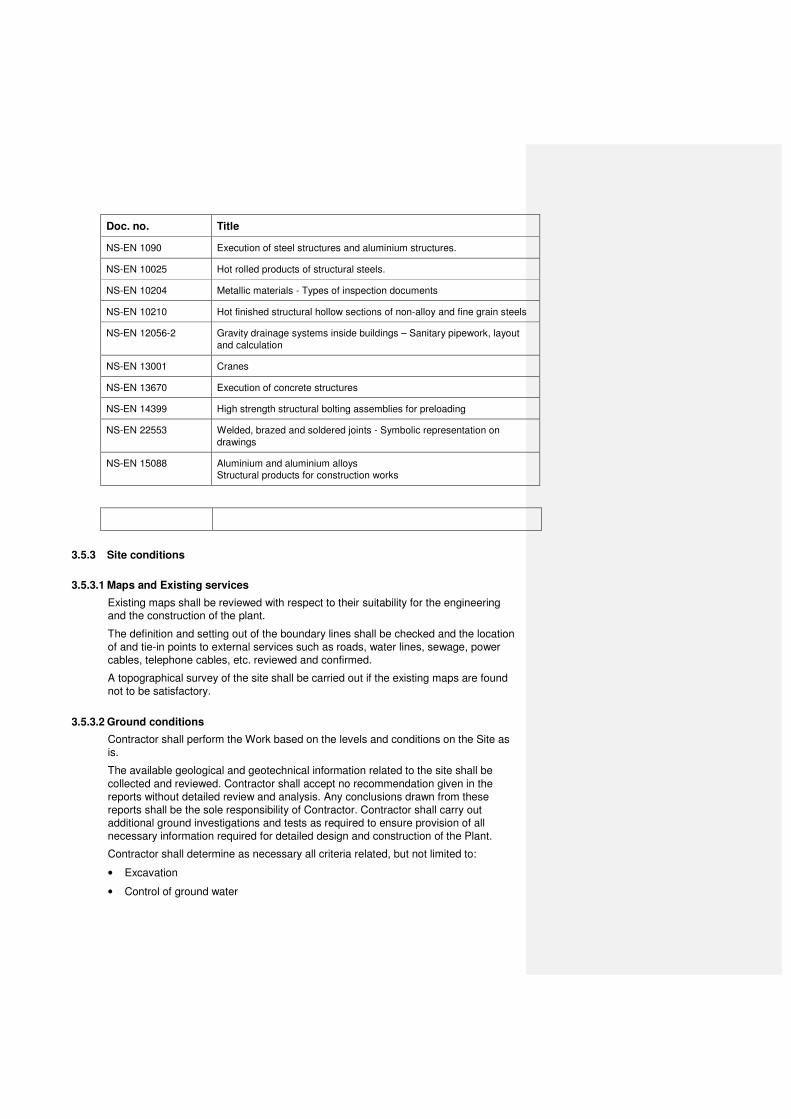
Doc. no. Title
NS-EN 1090 Execution of steel structures and aluminium structures.
NS-EN 10025 Hot rolled products of structural steels.
NS-EN 10204 Metallic materials - Types of inspection documents
NS-EN 10210 Hot finished structural hollow sections of non-alloy and fine grain steels
NS-EN 12056-2 Gravity drainage systems inside buildings – Sanitary pipework, layout
and calculation
NS-EN 13001 Cranes
NS-EN 13670 Execution of concrete structures
NS-EN 14399 High strength structural bolting assemblies for preloading
NS-EN 22553 Welded, brazed and soldered joints - Symbolic representation on
drawings
NS-EN 15088 Aluminium and aluminium alloys Structural products for construction works
3.5.3 Site conditions
3.5.3.1 Maps and Existing services
Existing maps shall be reviewed with respect to their suitability for the engineering and the construction of the plant.
The definition and setting out of the boundary lines shall be checked and the location of and tie-in points to external services such as roads, water lines, sewage, power cables, telephone cables, etc. reviewed and confirmed.
A topographical survey of the site shall be carried out if the existing maps are found not to be satisfactory.
3.5.3.2 Ground conditions
Contractor shall perform the Work based on the levels and conditions on the Site as is.
The available geological and geotechnical information related to the site shall be
collected and reviewed. Contractor shall accept no recommendation given in the reports without detailed review and analysis. Any conclusions drawn from these reports shall be the sole responsibility of Contractor. Contractor shall carry out additional ground investigations and tests as required to ensure provision of all necessary information required for detailed design and construction of the Plant.
Contractor shall determine as necessary all criteria related, but not limited to:
• Excavation
• Control of ground water
• Filling and compaction
• Settlements
• Ground improvement
• Shallow foundations
• Piled foundations
• Determination of ground water level ranges
• Liquefaction potential
• Chemical attack on buried concrete
• Dynamic analyses design criteria
• Contamination of soil and ground water
All site investigations and laboratory testing shall comply with the recommendations set out in the relevant standards, reference is made to BS EN 1997-2, BS 1377, BS 5930 and QCS 2007.
3.5.3.3 Previous site preparation works
The site was
3.5.4 Design briefs and method statements
3.5.4.1 Design briefs
The basis for the design works covering all parts of the plant shall be documented in the form of Design Briefs to be prepared prior to start of design work.
Design briefs shall describe, but not be limited to:
• List of standards
• Description of calculation method and software
• All loads and principles for load combinations
• Key design criteria and assumptions
• Materials selection
• Level of control
3.5.4.2 Method statements
Contractor shall prepare a written method statement including plans for testing and
inspection not less than 21 Days prior to commencement of the Work. The method statements shall comprise a detailed description of the Work. This document shall be issued to Company for review.
The method statements shall cover all activities for the Work and include, but not be limited to:
• Construction sequence and phasing
• General site development
• Demolishing
• Ground improvement

• Excavations and backfill
• Foundations and piling
• Concrete structures
• Steel structures
• Buildings
• Routing for pipelines and cables, crossings
• Sewage systems
• Drainage systems
3.5.5 Design requirements
3.5.5.1 General
All documents including communication, specifications, analysis, results, reports and design briefs shall use the Limit State Design approach (semi probabilistic design concept). Alternative concepts (e.g. working load concept and allowable stress concept) shall be converted to equivalent quantities in terms of Limit State Design approach.
3.5.5.2 Coordinates and levels
The local plant coordinate system shall be used.
Ground floor slabs in buildings shall be raised up to a minimum of 150 mm above the surrounding ground or paving level.
Structural steel columns shall be placed on plinths which shall be raised minimum 200 mm above floor level in buildings and above paving/ground level outdoors.
3.5.5.3 Design and design supervision
In general, all design shall be based on NS-EN 1990-1998 and all requirements referred to herein. NS-EN 1990 outlines the determination of Consequence Class (CC) and Reliability
Class (RC). This classification is the basis for later determination of Execution Class (EXC) and associated verification and inspection level during design and fabrication.
CC2 CC3
Engineering:
Design supervision level (DSL)
1 Self check X X
2 Independent colleague check X X
3 Third party or extended
independent colleague verification
X
Fabrication/construction:
Inspection level (IL)
1 Self inspection X X
2 Inspection according to
certified Factory Control Procedure
X X

3 Third party verification X
As default the CC3 (Extended consequence) shall be selected for all main structures deemed critical for operation of the plant. All deviation from CC3 shall be pre-approved by Company.
In parallel, the requirements for independent verification and inspection according to local regulatory requirements shall be fulfilled.
All classification for design and execution shall be performed during start-up of the design phase.
Design and verification shall only be performed by companies with approval according to the National regulations. Selection of Third Party Verification Company shall be subject to Company acceptance.
3.5.5.4 Materials and workmanship
Basic materials choices shall be substantiated and documented. The durability of structures and future maintenance shall be considered especially in areas with a corrosive environment.
Requirements to workmanship and tolerances shall be specified on the drawings
based on the functional requirements and the subsequent construction and installation activities.
Testing and quality assurance of civil construction work shall be comprehensive and in accordance with accepted international practice. Construction control requirements, i.e. control of construction methods, materials and workmanship, shall be documented and be in accordance with applicable standards.
3.5.5.5 Loads
3.5.5.5.1 General
The local conditions shall be identified and all relevant loads shall be established. The proposed loads shall be presented in the Design Brief.
A system for naming and numbering of basic load cases and load combinations shall be established.
Unless more stringent requirements are given in the various parts of NS-EN 1991 “Eurocode 1: Actions on structures” or other standards valid for the project, or in requirements for specific structures, the following minimum loads shall apply. All loads specified below are characteristic loads not including partial safety factors.
3.5.5.5.2 Vertical live load
Characteristic vertical live loads shall be determined and documented for each structural member, and shall not be less than specified below:
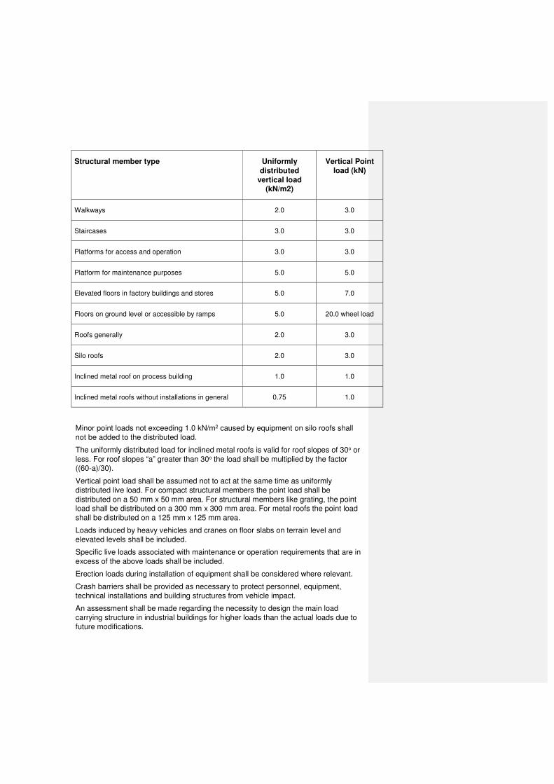
Structural member type Uniformly
distributed
vertical load (kN/m2)
Vertical Point
load (kN)
Walkways 2.0 3.0
Staircases 3.0 3.0
Platforms for access and operation 3.0 3.0
Platform for maintenance purposes 5.0 5.0
Elevated floors in factory buildings and stores 5.0 7.0
Floors on ground level or accessible by ramps 5.0 20.0 wheel load
Roofs generally 2.0 3.0
Silo roofs 2.0 3.0
Inclined metal roof on process building 1.0 1.0
Inclined metal roofs without installations in general 0.75 1.0
Minor point loads not exceeding 1.0 kN/m2 caused by equipment on silo roofs shall not be added to the distributed load.
The uniformly distributed load for inclined metal roofs is valid for roof slopes of 30o or
less. For roof slopes “a” greater than 30o the load shall be multiplied by the factor ((60-a)/30).
Vertical point load shall be assumed not to act at the same time as uniformly distributed live load. For compact structural members the point load shall be
distributed on a 50 mm x 50 mm area. For structural members like grating, the point load shall be distributed on a 300 mm x 300 mm area. For metal roofs the point load shall be distributed on a 125 mm x 125 mm area.
Loads induced by heavy vehicles and cranes on floor slabs on terrain level and elevated levels shall be included.
Specific live loads associated with maintenance or operation requirements that are in excess of the above loads shall be included.
Erection loads during installation of equipment shall be considered where relevant.
Crash barriers shall be provided as necessary to protect personnel, equipment, technical installations and building structures from vehicle impact.
An assessment shall be made regarding the necessity to design the main load carrying structure in industrial buildings for higher loads than the actual loads due to future modifications.

3.5.5.5.3 Horizontal live load
Characteristic horizontal live load on handrails for platforms, walkways and staircases shall not be less than 1.0 kN/m. The live load shall be assumed to act perpendicular to the top of the handrail, but not higher than 1.2 m.
3.5.5.5.4 Wind loads
Wind loads shall be calculated in accordance with NS-EN 1991-1-4 “Eurocode 1: Actions on structures. Part 1-4: General actions – Wind actions”. Reference is made to section 1.6.
Local topographical effects for the site shall be evaluated and reflected in the determination of wind loads.
Dynamic effects of wind shall be considered for slender structures, such as chimneys and similar.
Roof cladding, wall cladding and large doors including fixing to the sub-structure shall be designed for loads according to Eurocode 1 multiplied by 1.2.
3.5.5.5.5 Snow loads
Snow loads shall be calculated in accordance with NS-EN 1991-1-3 “Eurocode 1:
Actions on structures. Part 1-4: General actions – Snow actions”. Reference is made to section 1.6.
3.5.5.5.6 Thermal loads
Thermal expansion shall be considered for concrete and steel structures. Building structures shall be designed for temperature variations as given in section 1.6.
For unprotected structures additional temperature loads caused by radiation shall be considered.
Loads from temperature gradients in materials shall be considered.
3.5.5.5.7 Explosion loads
Explosion loads on buildings and civil facilities shall be assessed and calculated if
necessary.
The impact on buildings and facilities shall be identified and alternative methods of pressure relief or protection shall be considered incorporated. Such measures may be in the form of pressure relief panels, increased ventilation, protection walls, or structural design of the building or facility to withstand the explosion loads. The
solution to be adopted shall be in accordance with the design accidental load calculations.
3.5.5.5.8 Earthquake loads
Buildings and structures shall be designed to resist seismic events in accordance with NS-EN 1998 “Eurocode 8: Design of structures for earthquake resistance”. Reference is made to section 1.6.

3.5.5.6 Displacements
Unless more stringent requirements are given in the codes and standards valid for the project, or in requirements for specific structures, the following maximum
deflections and displacements shall apply for calculated values in the serviceability limit state:
Roof: Beams/slabs/cladding L/200
Floor: Main beams L/400
Floor: Secondary beams L/250
Cantilevered structure L/200
Columns / frames H/300
Crane beams L/1000
Crane beams for light duty cranes L/600
Cantilevered crane beams L/500
Crane beams horizontally L/600
Wall purlins/roof girders L/200
The requirement to light duty cranes applies to cranes with total weight less than 50 tons, including SWL.
For all crane beams the crane manufacturer’s requirements shall be complied with.
The values above refer to total deflections, i.e. including deflections from dead loads.
Deflection for dead load may be compensated by introduction of super-elevation / precamber. This shall be clearly specified on drawings.
3.5.5.7 Expansion joints
Measures shall be included in the design to accommodate thermal movements, and expansion joints shall be provided where necessary. These shall be fully effective and construction shall provide for complete weatherproofing on completion.
Joints in building construction shall be according to the guidance in BS 6093 “Design of joints and jointing in building construction. Guide”.
3.5.6 Technical requirements
3.5.6.1 Site works
3.5.6.1.1 Clearance of Site
Clearing of the site shall be undertaken in accordance with the site preparation plan.
Any unsuitable soil, surplus vegetation, contaminated soil, other foreign material, buried obstacles which may affect the construction work shall be removed and be brought to a disposal site.
Voids formed by removal of buried items shall be backfilled with specified fill material and compacted as site fill.
Existing services shall be identified prior to site clearance and necessary precautions taken when performing work.

Burning of materials arising from the clearing of the site or other activities is strictly forbidden on Company’s site.
Demolished material shall be removed from Company’s site without delay and disposed in accordance with environmental requirements.
Pre-loading of the site shall be performed as specified in the geotechnical report in order to limit later ground settlement.
3.5.6.1.2 General earthworks
All areas shall be cleared, filled, compacted and levelled to the levels specified on the
engineering drawings. Compaction shall be according to requirements to normal compaction in NS 3420 and NS 3458.
There shall be documentation by test pits that unsuitable soil has been removed from the area.
Excess materials shall be removed from Company’s site or stock piled according to specifications given by Company.
If the levels are such that no filling is required, the existing soil shall be compacted to the requirements. In case the required soil modulus and density are not achieved, the soil shall be removed, replaced and compacted to the requirements specified.
All fill material shall be well graded blasted or crushed rock and shall be compacted in
layers according to requirements. For this type of material, well graded is defined as material that contains particles of a wide range of sizes and has a good representation of all sizes. Crushed concrete can be used in the sub base for roads. The recommendations/rules in the Norwegian Public Roads Administration’s Handbook no. N200, shall be followed.
Maximum rock size is 2/3 of layer thickness, restricted to 400 mm for fill lower than 1 m below foundation level and 120 mm for the upper 1 m below foundation level. Maximum allowed fines content is 5%. Fines content is defined as particle size less than 0.075 mm of material less than 19 mm.
Los Angeles tests shall be carried out on fill material to demonstrate the suitability with respect to rock quality. The Los Angeles value shall not be higher than 25.
Selected excavated material may be used for filling provided the requirements are fulfilled.
Maximum layer thickness depends on the compaction equipment used and shall be taken according to NS3458; "Compaction – Requirements and Execution" Table 2,
Material Group B, Crushed Aggregates. For Material Group A, Blasted Rock, the maximum allowed layer thickness shall be 0.7 m.
When filling up new area’s for erecting of construction’s a test program for filling
operations shall be prepared. This shall include compaction tests at Site to determine optimum number of passes for each type of compaction equipment to be used:
1. Establish a test area. If suitable, this can be as an integrated part of the fill. The test area should be approximately 10x20 meters. The layer thickness shall be according to the requirements.
2. Level the fill surface (at least 20 locations) to obtain a reliable average level. The
levelling spots shall be marked on the fill surface to level the same spot after each pass by the compactor.

3. Perform one pass with compactor
4. Level the surface
5. Perform one more pass with the compactor
6. Level the surface
7. Repeat this procedure for every pass with the compactor up to 10 passes.
8. Present the test results in diagrams with number of passes on the horizontal axis
and average settlement on the vertical axis. Necessary number of passes shall be determined based on average settlement achieved for the last pass. This shall be less than 5 ‰ of the layer thickness.
The final grading shall be undertaken to obtain the finished surfaces, elevations and
slopes in various areas as shown on drawings with tolerances +/- 50 mm for general areas and +/- 20 mm for areas underneath foundations and structures.
Excavations for foundations, pits and trenches shall be carried out in a safe manner. For deep excavations sheet piling, shoring walls or similar and dewatering systems shall be designed as required.
Contractor is responsible for all required precautions due to water during ground investigations, excavations and construction work.
Water shall be removed from excavations before pouring concrete and the excavation shall be kept dry until after the concrete has set.
No snow, ice or frozen materials is permitted in fills.
Warning tape shall be provided above cables and pipes.
3.5.6.1.3 Site drainage during construction
Contractor shall design and establish drainage facilities for surface water as required to prevent flooding on site during construction.
3.5.6.2 Roads and paved areas
3.5.6.2.1 General
The layout, routing and elevation of roads, tracks, walkways and paved areas shall be shown on layout drawings.
Roads shall provide vehicle access for operation and maintenance as required in the plant. Two independent access routes shall be provided for emergency vehicles.
A system of walkways and sidewalks shall be provided for the pedestrian traffic to and in the plant area. Minimum width of walkways shall be 1.2 m. All access points to buildings shall have paved walkways to the entrances.
Where sidewalks are constructed along roads, raised curbs shall be provided. The road shall have fall to gullies connected to the surface water drainage system.
Traffic signs, road signs and marking shall be provided.
Roads and paved areas shall be provided with lighting.
3.5.6.2.2 Roads
Roads, bridges, culverts, pipe crossings and all other drivable areas shall be designed for all vehicles and equipment loads which may appear. The design loads

shall not be less than those used for design of public highways. The design and construction shall be such as to give durable roads and areas not requiring frequent upgrading or repairs.
Design axle load shall, as a minimum, be a semi-trailer with following axle loads and dimensions:
Axle load 200 kN
Axle centers 4 m, 1.5 m
Track 2 m
Footprint of wheel 0.3 m diameter
Requirements due to construction activities, lifting operations, transport of equipment, etc. shall be considered and necessary modifications taken.
Requirements to road widths shall be as follows:
• Typical plant roads shall have paved width 6 m plus 0.5 m paved shoulders on
both sides, total width 7 m and minimum designed in according to “Statens vegvesen Håndbok N200.
• Special purpose extra wide roads shall have paved width 8 m plus 1 m paved shoulders on both sides, total width 10 m.
• Secondary local access roads shall have paved width 4 m plus 0.5 m paved shoulders on both sides, total width 5 m.
Road widths shall be adequate for the operational traffic pattern.
All roads shall have minimum transverse cross fall 2% to each side, the high point being the center line of the road. Longitudinal gradients shall not exceed 5%.
In addition to the paved shoulders all roads shall have 1 m shoulders on both sides
formed of crushed fill. Areas with landscaping, paving, sidewalks etc. may be exempt. The fill shall be compacted in the same manner as the sub base and finished with 50 mm /aggregate with particle size lower or equal to 25 mm/ crushed rock.
Roads and traffic areas shall generally have a two-layer asphalt paving. The top layer of asphalt shall be established late in the construction period.
Concrete paving or similar shall be used for roads with Al-tapping vehicle traffic
between potroom and casthouse, transport of lined cathodes between cathode relining shop and potroom and otherwise only where necessary for operational safety, maintenance or specific reasons (e.g. high frequency maneuvering or
loading/unloading of heavy trucks such as alumina trucks). Concrete roads shall in general have brushed surface.
Services and pipelines passing beneath roads and areas subject to traffic shall be protected as required to withstand the impact from traffic loads, covering both the construction and operation phase.
The free clearance height above roads shall in general be minimum 5 m.
Crash barriers shall be provided as necessary to protect personnel, equipment, pipelines and buildings from vehicle impact.
Utilities and pipelines crossing over roads shall be protected by separate horizontal
steel beams or structures positioned 0.5 m lower than the pipeline rack. The free clearance defined above shall be maintained to the steel beams.
3.5.6.2.3 Paved areas
The loads on the paving shall be evaluated based on operation and maintenance requirements and relevant loads from the construction and installation activities.
Wheel loads from heavy equipment and loads from outriggers on cranes shall be considered.
Design criteria for the paving may be defined for two classes, light duty and heavy duty, if this is found to be practical.
Paved areas shall be provided with gradients and channels for easy run-off of water, minimum slope on paving shall be 1:70. There shall always be a gradient away from the buildings. Slope of ramps to doors shall not be steeper than 1:20.
Concrete paving shall be provided in all areas where handling and storage of scrap metal, materials, products and waste will be carried out.
Asphalt paving shall be provided in parking areas for light vehicles and cycles. Walkways and areas for pedestrians shall have asphalt or interlocking concrete blocks.
Unpaved areas shall be surfaced with minimum 100 mm gravel or landscaped with vegetation. Generally, graveled areas shall have a gravel surface on a base that allows light traffic and also drain-off into the ground of surface water.
A polythene sheet with minimum thickness 0.2 mm shall be provided between the
sub grade and concrete paving. Concrete paving shall in general have brushed surface.
A paving plan showing type of paving and surfacing for all areas and the respective loads shall be prepared.
3.5.6.3 Sewage and drainage systems
3.5.6.3.1 General
All drainage and sewage systems shall be designed and constructed to be capable of carrying away all flows discharged into it without blockage and requiring a minimum
of maintenance. The system shall be constructed of durable materials and with adequate capacity, satisfactory gradients and access for inspection, maintenance and testing.
Layout drawings with main co-ordinates and levels for all underground piping and
drainage channels shall be prepared. The drawings shall show location of manholes and inspection chambers and details of road crossings.
Underground piping shall as far as possible be located outside a zone extending 45o from the edges of any load bearing foundation to avoid under-excavation.
Top of manholes and catch basins shall be flush with paving in paved areas. In unpaved areas top of manholes shall be 150 mm above finished grade. Heavy-duty covers designed for a wheel load of 100 kN shall be used where traffic loads are possible. Concrete channels shall have cover by heavy-duty grating. Sand traps of minimum 1.0 m of depth shall be provided in all catch basins.

3.5.6.3.2 Sewage systems
The system shall collect untreated sanitary sewer including relevant wastewater and kitchen drains from all buildings. A grease trap shall be supplied for treatment of kitchen drain water.
The sanitary sewer system shall be designed for the number of people present in the plant based on 24 hours operation, and the expected water consumption, taking periods with high frequency of use of the washing facilities into consideration.
The sewer system shall be designed as a gravity system with self-cleaning velocities wherever possible and equipped with pumping stations where necessary.
Vacuum sewer systems or closed sewage tank system with periodic collection may be used subject to Company acceptance.
3.5.6.3.3 Surface water drainage systems
The surface water drainage system shall collect clean storm water from uncontaminated areas and roofs of buildings.
The water shall be collected through a system of channels, trenches and/or
underground piping and disposed of in accordance with the requirements of the local requirements and local authorities.
The quantity of rainwater to be discharged shall be based on local precipitation data given in section 1.6. The following run-off coefficients shall be used.
• Roofs: 1.00
• Paved areas: 0.90
• Unpaved areas (gravel, grass etc.) 0.50
Drainage from areas where the water can be contaminated with oil or chemicals shall be collected separately and treated before it is disposed of in accordance with the requirements of the local authorities.
3.5.6.3.4 Materials and workmanship
Special attention shall be paid to selection of pipe material where hot effluents are to be discharged.
Manholes and channels shall be constructed of reinforced concrete. Manholes and channels in which corrosive chemicals are present shall be lined with tiles or coating resistant to the actual chemicals.
Manholes and inspection chambers shall be constructed and completed concurrent with their adjoining lengths of pipe work. After the pipes have been tested, granular
material shall be carefully placed and compacted around and above the pipe to a height of at least 150 mm above the crown of the pipe.
At road crossings and in areas subject to traffic, pipes shall be designed for traffic loads if not protected by other measures.
3.5.6.4 Concrete structures
3.5.6.4.1 General
Design of reinforced concrete structures including buildings and foundations shall be
in accordance with the various parts of NS-EN 1992 “Eurocode 2: Design of concrete structures”.
The design of concrete structures shall consider, but not be limited to loads, soil properties, settlements, shrinkage, creep, temperature effects, environmental exposure and durability.
All properties relevant for structural analysis shall be developed for the concrete mix specified.
The expected maximum strength of the concrete shall be investigated and appropriate measures in the design, particularly with respect to the required minimum reinforcement shall be taken.
Post-tensioned reinforcement may however be used in hoop direction in large silos if
crack width requirements cannot be fulfilled with un-tensioned reinforcement, which shall be documented. In case of post-tensioned reinforcement, the concrete shall not
experience tensile stresses during Serviceability Limit State (SLS) for axis-symmetrical loads caused by silo content.
All faces of concrete sections shall have reinforcement, including faces towards ground. This requirement does not apply to sections designed as unreinforced concrete, e.g. paving slabs and road slabs.
Edge protection shall be provided in areas with traffic, in joints, at doors and gates etc. as required to prevent spall off of concrete.
Exposure Class: XF4/XS1. For structures in contact with seawater or sea spray:
XF4/XS3
Durability Class: MF45. For structures in contact with seawater or sea spray: MF40.
Cement: CEM II/A-V-42.5 R (FA cement). Minimum cement content: 360 kg/m3
Silica: Content 5-10 %. The k-parameter shall be 1.0
3.5.6.4.2 Crack widths
Special attention shall be paid to the limitation of cracks in concrete. For all concrete members it shall be documented that the below requirements are met.
Surfaces located inside air-conditioned buildings shall have crack widths less than 0.30 mm.
All other members shall have crack widths less than 0.20 mm unless otherwise specified in section 2.
3.5.6.4.3 Embedded steel
All embedded items including anchor bolts shall be hot dip galvanized, and protruding
surfaces shall in addition be painted. Measures shall be taken to prevent negative chemical effects due to contact between fresh concrete and embedded hot dip galvanized steel.

Anchor bolts shall always be located inside the reinforcement frame.
Fixed location frames or corrugated sleeves shall be used for anchor bolts to secure correct position.
3.5.6.4.4 Grouting
Non-shrink grout with expanding properties shall be used for all grouting works. The grout shall have a compressive strength at least equal to the concrete. Epoxy grouting shall in general be used for rotating equipment.
Type of grout shall be chosen based on the specific conditions for the actual
foundation and the manufacturer’s recommendations. The grout shall be mixed, applied and cured in full accordance with the manufacturer’s recommendations.
The concrete surface shall be properly cleaned and watered. All loose particles shall be removed. Redundant water shall be removed prior to grouting.
3.5.6.4.5 Foundations and ground floor slabs
Foundations shall be designed to withstand the imposed loadings and to restrict
settlements, such that the overall and differential settlements do not exceed allowable values.
Vibration analysis shall as required be performed to confirm that dynamic amplitudes
of foundations and structures for rotating and reciprocating equipment will not exceed the allowable values given by the equipment manufacturer, but these shall not exceed VRMS = 2.8 mm/sec.
Foundations subject to vibration shall be isolated from adjacent structures.
Foundations for rotating and reciprocating equipment shall be in accordance with BS CP 2012-1 "Code of practice for foundations for machinery. Foundations for reciprocating machines" and DIN 4024 “Supporting Structures for Rotating Machines”.
Foundation plinths for structural columns and equipment leg supports shall extend not less than 50 mm from the edges of base plates 0.2 m2 and less in area, and 75 mm for base plates more than 0.2 m2 in area.
Foundations subject to overturning moment shall have an effective width of minimum 400 mm
Foundations for equipment such as pumps and compressors shall extend not less
than 75 mm from the edge of base plates except when otherwise specified on the manufacturer's drawings.
Generally, the top of footings shall be minimum 600 mm below plant level to allow underground routing of cables and piping.
All concrete foundations and reinforced concrete ground floor slabs shall be constructed on concrete blinding of minimum 50 mm thickness.
3.5.6.4.6 Containment bunds and basins
Contractor shall provide containment bunds around all equipment where there is a risk of oil or fuel spillage. Bund sizing shall be based on a containment of 110% of
largest tank volume or transformer capacity. Drainage of the bunded areas shall be controlled using water control devices to ensure that oil does not pass from the
containment basin into the plant drainage system. Oil shall be prevented from seeping into the ground by reinforced concrete floor and walls.
3.5.6.4.7 Transformer bays
Oil filled transformers shall be supported on adequately sized reinforced concrete
bases. Each transformer shall be enclosed by reinforced concrete walls as required to prevent the spread of fire and limit the effects of an explosion within the enclosure. Bay sides without concrete walls shall be provided with suitable removable fence fitted with a lockable personnel access gate.
The bays shall be sized to permit safe working and provide room for installation,
maintenance, removal and cooling of the transformers. Contractor shall consider provision of light roofs over the bays. Rails shall be provided in front of the bays to facilitate easy rolling in and out of transformers.
Around the transformer base a containment basin with slope towards a pump pit shall
be designed to collect oil spillage, rainwater and firefighting water. Drainage facilities shall be provided. The basin shall be covered by a fire protecting gravel stone layer/grating according to section 3.3.3.
3.5.6.4.8 Tolerances and workmanship
Reinforcement shall in general comply with the requirements in NS-EN 10080 “Steel
for the reinforcement of concrete – Weldable reinforcement steel”.
Concrete mix and all ingredients shall comply with the requirements in NS-EN 206 “Concrete. Specification, performance, production and conformity”.
All construction work on site shall follow the requirements in NS-EN 13670 “Execution of concrete structures”.
Fabrication of prefab concrete elements shall comply with NS-EN 13369 “Common rules for precast concrete products”.
The tolerances given for Tolerance Class 1 in NS EN 13670 “Execution of concrete
structures” including Annex G shall apply unless more strict tolerances are required for particular works.
Abrupt change of level or dimension shall be less than 2 mm for exposed surfaces and less than 5 mm for not exposed surfaces.
3.5.6.5 Steel and aluminium structures
3.5.6.5.1 Materials
Steel grades according to NS EN 10025 “Hot rolled products of structural steels” and NS EN 10210 “Hot finished structural hollow sections of non-alloy and fine grain steels” shall be used.
All steel materials shall be documented by certificate 3.1 according to NS EN 10204
“Metallic materials. Types of inspection documents”. This documentation shall be traceable throughout the fabrication process.
Crane girders shall be of steel grade S355J2 according to NS EN 10025.
Generally, the same grade shall be used for all structural steel throughout the contract, with possible exception for crane girders.

The possibility of brittle failure at low temperatures shall be considered when selecting steel material. The selection of steel grades and material properties (low
temperature brittle behavior, through-thickness properties etc.) shall comply with the procedures in NS-EN 1993.Selection of steel grades shall be substantiated and submitted to Company for acceptance.
Steel plates subjected to tension perpendicular to the plate surface shall be verified for through thickness properties.
Material in stiffener plates, end plates, gusset plates, etc. shall be of the same steel grade as the section they connect to.
Aluminium grades shall be selected according to NS-EN 15088.
3.5.6.5.2 Design
Steel structures shall be designed according to the various parts of NS EN 1993 “Design of steel structures”. The engineering documentation shall include all relevant
requirements as listed in tables A1 and A2 in Appendix A of NS-EN 1090. Defined requirements to execution class for structures, components and connections shall be shown on the structural drawing or included in the BIM model.
Aluminium structures shall be designed in accordance with NS-EN 1999 “Design of aluminium structures”
Design of structural steel shall be such that potential corrosion traps are avoided. All
parts of steel structure shall have access for inspection, cleaning and painting. Angles and channels shall be designed and oriented such that collection of dust and humidity is avoided. Back to back angles shall be avoided. If hollow sections profiles are used, they shall be sealed in both ends.
Structural members shall have a thickness not less than 5 mm including webs of rolled sections, purlins and sheeting rails.
Contractor shall prepare table of steel sections to be used in design, before any design work starts. The number of sections shall be limited. European sections according to Euronorms shall be used.
The thickness of gusset plates shall not be less than 10 mm, and the thickness of base plates shall not be less than 15 mm.
Plastic cross-section design shall not be used for crane girders. The top flange only shall transfer horizontal actions on the crane girder.
All structures shall be designed to facilitate erection, and they shall also be designed
to remain stable at all stages during erection. If necessary, suitable temporary bracings or supports shall be designed and provided.
3.5.6.5.3 Tolerances
Tolerances shall generally be in accordance with requirements in NS-EN 1090. Functional tolerance class according to NS-EN 1090 table D2 shall be specified on the structural drawings or included in the BIM model.
Unless more stringent tolerances are required the following shall apply:
• Deviation of theoretical length (L) of structural element +/-0.05%L
• Deviation of theoretical straightness (f of L) +/-0.10%L
• Deviation of theoretical position after erection, base/top of stanchion end of beam, etc. in all directions +/-5 mm
Tolerances for rails for cranes and other moving equipment shall be as specified by the crane manufacturer.
Requirements to anchor bolts are given in another section.
3.5.6.5.4 Connections
Connections shall be chosen and designed to reduce the risk for corrosion and to minimize maintenance costs.
Workshop connections shall generally be welded. Site connections shall be bolted.
No field welding shall be permitted for structural steelworks unless accepted by Company.
Welded connections shall have continuous welds. Minimum weld size is leg length z = 6 mm/ throat thickness a=4 mm. Intermittent welds shall not be permitted.
NS-EN 22553 " Welded, brazed and soldered joints. Symbolic representation on drawings” shall be used for symbolic information on drawings. Fillet welds shall be specified by their leg length z / throat thickness.
Bolts for bolted connections shall be partly threaded metric hexagon bolts, with
washers and nuts in accordance with the relevant standard. Bolt, nut, washer assemblies shall be provided by the same manufacturer.
Bolted connections:
• All material for bolted connections shall comply with requirements in NS-EN 15048, Non-preloaded bolting assemblies.
• Material grade 8.8 for screws
• Material grade 10 for nuts
• Hardness HV200 for washers ref NS-EN ISO 7089
• Washers shall be provided under the head and under the nut
• All bolting material shall be hot dip galvanized according to NS-EN ISO 10684
• Material certificate 3.1 according to NS-EN 10204, Metallic products. Types of
inspection documents
Minimum bolt diameters to be used:
• Secondary structures such as handrails and ladders 12 mm
• Secondary structures such as walkways and platforms 16 mm
• Other structures 20 mm
• Anchor bolts 20 mm
• Anchor bolts for secondary structures 16 mm
All bolted shear connections shall be bearing type; friction type connections shall not be used. Load transfer due to friction shall not be included in capacity.
Bolted connections shall have a minimum of 2 bolts. The threaded part of a bolt shall not be along a section subject to shear stresses. Threaded bolts protrusion after

tightening shall be according to requirements in NS-EN 1090, but not less than 1 x bolt diameter.
Contractor shall specify torque value for each bolt size.
Bolts connecting members supporting vibrating equipment or otherwise being exposed to vibration shall have lock washer or other equivalent system to prevent loosening.
All items in bolted connections and fastenings including anchor bolts (bolts, nuts,
washers, etc.) shall be painted in accordance with the surface treatment requirements given in Chap. 2.7, Specification for surface treatment.
Specified dimensions shall be met after galvanizing. The zinc coating on threads shall not be subject to cutting, rolling or finishing tool operation. Nuts may be tapped after galvanizing.
Corrosion allowance for bolts shall be considered. Corrosion allowance for anchor bolts shall be 2 mm on nominal diameter.
All connecting parts shall be chosen and designed to avoid galvanic corrosion.
Preloading of bolts shall be assessed with regards to connection stiffness and fatigue.
Special consideration shall be given to preloading of anchor bolts for deformation critical connections and connections exposed to fatigue loads. The level of preload
shall be sufficient during the life time of the structure, including the effect of creep and shrinkage of the concrete.
3.5.6.5.5 Fabrication and erection
Workmanship, quality control and documentation shall be in accordance with NS EN
1090-2 “Execution of steel structures and aluminium structures. Part 2: Technical requirements for the execution of steel structures”.
Fabrication and welding shall be done under shop conditions.
Contractor shall provide workshop facilities for welding and surface treatment close to site in case of repair or modification of prefabricated steel sections.
Components shall be handled carefully during fabrication, transportation, storage and erection to avoid damages to steelwork and painting.
Care shall be taken to ensure that all components of the assembled structure fit together accurately. Force shall not be used to correct misfits.
Thermal expansion due to temperature differences between fabrication site and construction site shall be considered with respect to erection tolerances.
Shim plates used for alignment of equipment and structures shall be hot dip galvanized if being part of the permanent structure.
No equipment shall be installed or loads imposed until correct position and alignment has been obtained and the structure is securely connected and grouted to its foundation.

3.5.6.6 Stairs, ladders, walkways, platforms and handrails
3.5.6.6.1 General
Stairs, ladders, walkways, platforms shall be provided to give safe access to
structures and equipment for operation and maintenance.
Stairs shall be straight and the inclination shall be equal for all flights in multi flight staircases.
Spiral stairs shall only be used in exceptional cases and on Company’s acceptance.
The inclination shall be equal for all flights in multi flight staircases. The inclination shall in general be between 30o and 38o.
The going g and the rise r shall as a general guidance meet the following formula: g + 2r = 630 mm +/-30 mm.
All walking surfaces shall have a non-slip finish.
3.5.6.6.2 Material selection and design
Walkways and stair treads shall in general have gratings. Gratings shall be hot
dipped galvanized according to section 3.7.4, and the minimum size of bearing member shall be 30 mm x 3 mm. Stair treads shall be delivered with serrated and slip resistant front edge.
Stairs and walkways in steel shall be hot dip galvanized. Handrails and ladders shall in addition be painted in accordance with applicable requirements in section 3.7.4. All parts shall be prefabricated in the workshop prior to galvanizing, and no cutting or welding on site will be permitted.
Stairs and walkways in aluminium shall be fabricated from alloys resistant to the
marine and industrial environment. All bolted connections shall be made using minimum grade A4 stainless steel bolts. Direct contact between carbon steel and
aluminium shall be avoided. For low load connections such segregation can be obtained using neoprene sheets, synthetic washers, bushings etc.
For heavy loadbearing connections the isolation can be obtained by the use of grade 316L stainless steel washers and A4 bolt material
Polyester coated stainless steel flooring or fiberglass reinforced polyester grating shall be selected in areas with high risk for chemical corrosion.
All grating shall be fixed to the substructure using clamps, minimum four fasteners per panel. Welded or nailed studs are not permitted.
Removable floor plates shall be provided with two lifting keyholes at each end of the plate and Contractor shall provide four lifting keys.
3.5.6.7 Piling
Text Carbon Sunndal;
Design, installation and testing of piles shall be carried out in accordance with:
• NS-EN 1997-1 “Eurocode 7 Geotechnical design - General rules”
• “Peleveiledningen” published by Norsk Geoteknisk Forening
Contractor shall prepare a detailed Method Statement including all relevant details of
the method of piling and the plant he proposes to use. Contractor shall not commence any piling until the Method Statement has been accepted by Company.

Contractor shall submit pile records for each installed pile including all relevant data from installation, quality control and testing not more than two days after installation
of pile. In addition total pile records shall be submitted as part of the as built final documentation.
Text below this chapter is Qatar specific.
3.5.6.7.1 General
Design, installation and testing of piles shall be carried out in accordance with:
• BS EN 1997-1 “Eurocode 7 Geotechnical design - General rules”
• BS EN 1536 “Execution of special geotechnical work. Bored piles”
• “ICE Specification for Piling and embedded retaining walls”, by the Institution of Civil Engineers, published by Thomas Telford Ltd.
• QCS 2007
Contractor shall prepare a detailed Method Statement including all relevant details of
the method of piling and the plant he proposes to use. Contractor shall not commence any piling until the Method Statement has been accepted by Company.
Only bored concrete piles with use of steel casing during construction shall be considered. The pile diameter shall be not less than 750 mm. Piles shall be designed
to reach design capacity using friction between the pile shaft and competent bedrock only, and the contribution to capacity from end bearing shall be ignored. Negative skin friction on the pile shaft due to loose soil layers shall be considered.
Installation of piles shall be carried out in the shortest possible time to avoid inflow of water, erosion, etc.
The casing shall be driven into bedrock before excavation below the bottom of the
casing. Bedrock level shall be registered individually during driving of the casing for each single pile and recorded to verify that the casing is driven into bedrock. Ground investigation records shall only be used as a guideline to expected bedrock level.
Varying bedrock level for each single pile shall be allowed for. Drilling slurry (bentonite) shall not be used for stabilizing the soil.
All piles shall be founded into competent bedrock. The socketing length into competent bedrock shall be as determined by the design but not less than 3 times the diameter of the pile.
Concrete for use in piles, including testing, shall be according to Concrete
Specification. Reinforcement cages shall be installed before concrete placement. The maximum spacing of longitudinal reinforcement bars shall be 300 mm. Spacers to ensure sufficient concrete cover shall be installed on the reinforcement cage all along the pile with a maximum distance of 3 m. At least 3 spacers shall be installed at each level. The Method Statement shall give detailed information on type of spacers and handling of reinforcement cages.
Piles shall be installed within a tolerance of 75 mm of their true positions at cut-off level. Verticality shall be within 1 in 75. Maximum permissible deviation of a finished raking pile from the specified rake shall be 1 in 25. Maximum deviation of final cut-off
level from specified level shall be 25 mm. Where piles have not been positioned within these limits no method of forcible correction is permitted. Company may

require piles so positioned to be withdrawn and reinstalled or take such other action as considered necessary.
The top of the pile shall be brought above the required finished level of the pile head
by an amount sufficient to ensure a sound pile, but not less than 600mm. Surplus concrete shall carefully be removed in such a way that a horizontal and plane concrete surface for support of the superstructure is obtained. A vapor proof
separation of the pile tops from the pile caps, slabs or foundations being supported by the piles, shall be provided.
Contractor shall submit pile records for each installed pile including all relevant data from installation, quality control and testing not more than two days after installation of pile. In addition total pile records shall be submitted as part of the as built final documentation.
3.5.6.7.2 Testing
Contractor shall carry out pile testing to demonstrate that concrete integrity, pile
design capacity and pile deformation limits are achieved. Contractor shall prepare a pile testing plan including full details of testing methods that shall be subject to Company acceptance prior to commencement of any piling.
Initial testing shall consist of static load testing and cross hole sonic logging. Static load testing shall be carried out on 3 nos. of piles of each dimension. Cross hole sonic logging tests shall be carried out on 10 nos. of piles of each dimension. Piles subject to initial testing shall be selected among the first 20 piles installed with the relevant dimension.
Measures shall be taken on piles selected for static load testing to ensure that the pile will not have any end bearing. The static testing shall demonstrate that the
design load can be taken by friction between the pile shaft and the bedrock only according to design premises.
Further testing shall consist of static load testing on not less than 0.5 % of installed piles and cross hole sonic logging on not less than 5 % of installed piles.
Pile capacities shall be tested to 2.5 times the vertical and lateral loads determined in the serviceability limit state. Maintained test type shall be applied.
For cross hole sonic logging tests 4 nos. mild steel tubes with minimum 50 mm diameter shall be installed for the full length of the pile. The tubes shall be placed symmetrically around the pile cross section and firmly connected to the reinforcing cage. Testing shall be performed over the full depth with an interval not greater than 0.25 m. The tubes shall be backfilled with an appropriate cement grout upon completion of the testing.
Selection of piles for testing shall be subject to Company acceptance.
In addition to pile testing described above, all piles (included piles tested by static load and cross hole testing) shall be integrity tested by low strain sonic testing.
Testing and interpretation of low strain sonic testing and cross hole sonic logging testing results shall be performed by a specialist company. Name and professional qualifications of the engineer to perform the tests and the interpretation shall be given for Company acceptance prior to any testing. Piles with questionable results shall be subject to further investigation.

Pile testing results shall be submitted to Company for acceptance. If the testing reveals deficiencies in a pile, the pile shall be repaired or replaced, and the extent of testing on remaining piles shall be increased.
3.5.6.8 Accuracy in construction
Construction and assembly shall in general be according to BS 5606 “Guide to accuracy in building”.
3.5.7 Particular requirements to buildings
3.5.7.1 General
This section contains architectural, functional and other specific requirements to buildings.
The buildings shall provide:
• Optimum working environment for the people operating and maintaining the plant
• Protection of delicate equipment to obtain reliable and long lasting services under the local climatic conditions
• Protect personnel and equipment during emergency situations for safe operation and run down of the plant
The overall aim is to have cost efficient buildings with respect to construction, operation and maintenance.
The dimensions of all buildings shall provide adequate space for the safe installation and proper operation and maintenance of all plant and equipment.
All room areas and compounds containing equipment liable to fire or explosion shall be designed to safeguard personnel and minimize the effects.
Rooms containing large equipment shall be fitted with two access doors. One doorway shall be suitable for moving the largest item of equipment in and out, and the other shall comprise an alternative means of access for personnel.
Requirements to emergency doors are given in section 3.3.4. Emergency exit doors shall open outwards.
Administration buildings and buildings which are permanent work places shall be air-conditioned. Buildings or parts of buildings with air conditioning shall have thermal insulation in roofs and walls and air locks at the entrances.
Doors used only for transport of equipment or as emergency exits do not need air locks.
Buildings shall be closed and weather-tight unless otherwise specified.
The buildings shall generally be designed to allow for flexibility with regard to future extensions and internal arrangement modifications.
3.5.7.2 Overall architectural requirements
3.5.7.2.1 General
Architectural design shall follow the local regulations and building traditions and at the
same time provide modern, functional and durable facilities. Design principles shall be in harmony with those used for existing buildings.

The materials and colors to be chosen for the buildings, external and internal, shall be in harmony with each other, the surroundings and existing buildings. They shall be
based on the principles in the Architectural Philosophy and on the color schedule in section 3.5.8.
Design and finish of rooms and buildings shall generally ensure durability and easy cleaning.
3.5.7.2.2 Steel buildings
The roof angle for steel buildings shall in general be 11°.minimum?
The cladding of walls and roofs shall be vertically oriented corrugated aluminium sheets. To obtain daylight in the buildings, transparent sheets shall be applied where necessary. Alternatively windows made by aluminium profiles and glass shall be considered where appropriate.
The wall cladding shall be installed above a 1.2 m high dado wall made of reinforced concrete unless otherwise specified.
The cornices shall have curved sheeting.
3.5.7.2.3 Concrete buildings
Buildings made of reinforced concrete, concrete sandwich elements or plastered
reinforced block-work shall have external wall surfaces with a uniform horizontal groove pattern. Doors, windows, louvers etc. shall be integrated within this pattern. The details of the pattern shall be designed by the architect based on the selected Architectural Concept.
3.5.7.3 Design and materials
3.5.7.3.1 General
All materials shall have a good wear resistance and durable quality, suitable to local climatic conditions.
Load bearing structures for control rooms, switchgear rooms, substations and similar shall primarily be of in-situ cast reinforced concrete. Other solutions shall be approved by Company Reinforced block work may be used as infill between columns and beams.
Cable, pipe and services openings through roofs, floors and walls shall be sealed and
made smoke /fire proof after installation of cables etc. The sealing materials used for this purpose shall be fire resistant and easy to remove for the installation of further cables or services in the future.
Any cable basement shall be fully watertight reinforced concrete construction.
3.5.7.3.2 Roofs
Roofs shall be provided with access for inspection and maintenance and shall be
designed for the relevant loads including live loads related to inspection and maintenance.
Access shall be by stairs where required according to section 1. Roofs without stairs shall have access by permanent ladders.

Generally no equipment shall be installed on roofs except HVAC equipment. Architectural aspects shall be considered when placing equipment on roofs.
Gutters and down pipes shall be installed above all.
For buildings designed to have thermal insulation in the roof, the thickness of the insulation shall not be less than 100 mm. The insulation shall be mineral wool or
similar fire resistant type. Insulated roofs on steel structure buildings shall have double skin sheeting with intermediate insulation.
Insulation on concrete roof slabs may be of extruded polystyrene if covered with gravel or concrete tiles. Access routes shall have concrete tiles.
Membrane or roofing felt used as waterproofing shall have a minimum slope of 2 %. The water proofing and insulation shall be protected against UV-radiation.
3.5.7.3.3 Walls
Concrete buildings shall have external walls of reinforced concrete, concrete sandwich elements or reinforced blocks with internal treatment as described for
internal walls. External treatment shall be painted with silica paint. Or plastering for block work and 2 coats of cementitious, acrylic, decorative and protective paint on concrete and block work walls.
External walls of air-conditioned buildings shall have thermal insulation corresponding to minimum 50 mm of mineral wool or similar fire-resistant type. Insulated walls on steel structure buildings shall have double skin sheeting with intermediate insulation.
Principal interior walls shall be in masonry or concrete. Internal walls may for areas with offices, conference rooms, filing rooms and corridors be of removable light weight type, providing they meet the requirements for noise suppression and fire resistance. Wall finish shall be washable paint.
Minimum thickness for block work walls shall be 150 mm, except for toilettes and showers partitions and small rooms where 100 mm thickness may be used.
Walls facing kitchen, changing room, shower- and washroom and toilets shall be concrete or block work, plastered and with sealed joints. Wall finish shall be glazed ceramic tiles from floor to ceiling.
Walls facing to instrument- and computer room, electrical room and HVAC control room shall be painted concrete or block work, plastered and with sealed joints.
3.5.7.3.4 Cladding for steel buildings and sheds
Steel buildings and sheds shall have roof, Sinus profile ceiling, type, double overlap,
min 1 mm and wall cladding, type Trapeze profile wall, 1 mm, of corrugated aluminium sheets made from alloy or equivalent, subject to approval from Company. The minimum thickness of the sheets shall be 1.0 mm. Surface coating aluminum trim min 20 my PVF2 both sides
The cladding shall be electrically isolated from the steel structure. Use of galvanic insulation by use of wooden furring strips should be evaluated.
Fittings Al. 2. splash sale, top, transition, round recesses, 2.5 mm sand wind, tar
epoxy both sides, thickness Roofs industrial building 2.5 mm al. Sandsvipt, tar epoxy both sides, thickness.
Type of screws, stainless A4, length, number per meter, Calcots, one per. screw type sinus

Corrugated sheets used as waterproofing shall have sufficient slope and overlap at sides and ends to ensure a waterproof roof during all weather conditions. Sheets shall be sealed with sealant strips and flashing at the ridge and towards the walls.
Flashing and closure strips shall be installed at corners, windows and doors to provide a weatherproof building.
Foam fillers of durable material shall be provided and fixed to obtain closure at flashing. Foam fillers shall be completely covered by flashing for UV-protection.
In areas with risks for emission of corrosive chemicals, special considerations shall be given regarding the selection of suitable materials for cladding.
Translucent sheeting shall be installed to allow daylight into the buildings. The material shall be fire resistant and resistant to UV-radiation and chemicals to which it may be exposed.
Translucent sheets shall match the profile of the general sheeting and shall be laid and fixed at the same time as the cladding.
All necessary flashings, end closure pieces and other accessories shall be purpose made and of the same material as the sheeting. Minimum thickness of flashing is 2,5 mm.
3.5.7.3.5 Doors and windows
Windows shall have sealed double glazing of solar reflective type. The glazing shall
be etch resistant. The frames shall be stabile design and tightness for air, water and wind shall be documented. The frames shall be of solid tubular aluminium sections. All sun exposed windows shall be provided with sunshades.
All external doors shall be outgoing and equipped with double action hydraulic door closer and door stopper. External doors shall be of aluminium or stainless steel, designed with solid tubular sections and shall be provided with gaskets and stainless steel threshold to prevent water seepage, draught and dust intrusion.
External doors and windows may be of stainless steel if required due to fire resistance or mechanical strength, e.g. due to explosion loads.
Doors defined as emergency exits shall have emergency opener of easy release type.
Doors shall generally meet the requirements to fire rating and noise suppression
corresponding to the requirements to the wall where it is installed. Requirements to external doors may vary depending on location and arrangement of air locks.
Doors to instrument rooms, switch rooms and other technical rooms shall be large enough to allow easy transport of cabinets and other big and/or heavy units in and out.
Hinges, locks, etc. shall be of stainless steel.
3.5.7.3.6 Floors and stairs
Concrete floors in potroom shall have no surface coating.
Other floor slabs shall be of reinforced concrete provided with appropriate protective covering suitable for local conditions and intended use and easy to maintain and keep clean. Skirting shall be of the same material as the flooring and in matching colors.
Kommentert [ES1]: in painting and surface protection chap

Ground floor slabs shall be of watertight construction and provided with expansion joints as necessary. Other concrete floors shall, as a minimum, be coated with a dust
binding epoxy sealer. This also applies to concrete floors beneath raised computer floors.
Access steps or ramps shall be provided to gain entry to buildings.
Offices, conference rooms, filing rooms, corridors, etc. shall have PVC flooring of heavy duty type or other suitable heavy duty flooring, corresponding to expected level of occupancy, produced and tested in accordance with relevant standards.
Kitchens, changing rooms, shower rooms, washing rooms and toilets shall have glazed ceramic tiles with non-slip surface on all surfaces.
Emergency shower rooms and toilets shall have glazed ceramic tiles with non-slip surface on all surfaces.
HVAC rooms and similar technical rooms shall be epoxy coated with non-slip surface. The epoxy coating shall be continued as skirting 100 mm up the walls.
Control rooms, computer rooms, instrument rooms, electrical equipment rooms etc. shall have anti-static electrical grounded computer flooring where appropriate.
Floors in substations shall generally have epoxy coating. The flooring in switchgear-,
switchboard-, instrument- rooms, etc. shall be non- conducting, antistatic (dissipative) vinyl/rubber. Epoxy coating with similar or better electrical isolation properties may be used.
Battery room floors shall be protected against the electrolyte of the battery cells by using an acid resistant floor tiling or acid resistant epoxy coating.
Stairs and entrance areas shall have durable flooring easy to keep clean.
Floors in stores, product handling areas etc. shall be steel trowel finished concrete with a hardening additive. Further treatment shall be dependent on materials stored
and the chemicals to which the floors may be exposed. Floors in workshops shall in general have epoxy coating.
A non-skid surface shall be provided in areas with risk for oil spillage. Areas where chemical or oil spillage may occur shall be finished with chemical /oil-resistant materials.
Stairs shall be straight and the inclination shall be equal for all flights in multi flight staircases. The inclination shall in general be between 30o and 38o.
The going g and the rise r shall as a general guidance meet the following formula: g + 2r = 630 mm +/-30 mm.
3.5.7.3.7 Ceilings
All offices, conference rooms, canteen, corridors, control rooms, etc. shall have
suspended ceilings of perforated panels / mineral wool. The system shall be complete and incorporate necessary openings for lights and A/C diffusers and finished neatly with edge trims. Access panels shall be provided.
Concrete and plastered surfaces above the suspended ceiling shall be coated for dust proofing prior to start of installation works.
Concrete and plastered surfaces in rooms without suspended ceiling shall be painted.
Ceilings and painted finish in toilets, kitchen and lockers etc. shall be suitable for a damp atmosphere.

3.5.7.3.8 Plumbing and sanitary installations
The work shall be in accordance with NS-EN 12056-2: “Gravity drainage systems inside buildings – Sanitary pipework, layout and calculation” and satisfy the requirements of the local authorities.
All sanitary equipment shall be of good quality, easy to clean and maintain. Separate drainage systems for floor drains and sewage piping shall be provided. Drainage lines shall be designed to provide self-cleaning velocities and suitable access points for maintenance and clearing of obstructions. Drainage system shall prevent foul liquids or gases from flowing back into rooms.
Washrooms/locker room shall be equipped with:
• lockable lockers, 2 per person
• benches
• washbasins with liquid soap dispenser
• electrical hand dryers or paper towel dispenser
• mirrors
Toilets shall be equipped with:
• toilets
• wash basin with liquid soap dispenser
• toilet tissue dispenser
• mirrors
The size and numbers of equipment and installations shall be in accordance with the expected number of users.
3.5.7.3.9 Installations in buildings
Technical installations in the buildings shall wherever possible, be designed and constructed as concealed installations.
HVAC equipment shall be installed in purpose designed separate HVAC rooms as a general rule located at ground level.
Offices, laboratories, control rooms, conference rooms, workshops, etc. shall have ducting provided for the installation of communication and IT systems. Ducting shall be included in the building design for easy cable pulling and equipment installation. The ducting systems shall connect the separate buildings and be designed with 50 % spare capacity for future installations.
3.5.7.3.10 Locking system
In order to avoid admittance of unauthorized personnel to areas and/or rooms, a system for granting access to authorized personnel shall be implemented.
Following areas and/or doors shall have lock of mechanical type
• All doors shall have a lock of mechanical type which shall be incorporated into a master key system.
• Doors to electrical rooms and other technical rooms with restricted access shall have a dedicated lock and key system.
Following areas and/or doors shall have an electronic access control card system

• Entrance to the plant (e.g. main gate)
• Areas where especially sensitive processes are carried out and where information of vital importance to Company is handled or stored.
• Access to administration building, operations centres and other office facilities. Within such buildings it shall be possible to differentiate access to special areas.
In case of emergency (e.g. fire), the electronic access control card system shall not block emergency escapes routes.
The ownership of the system shall be Company and only Company shall have the right to order additional locks and keys to the system.
3.5.7.3.11 Furniture, fixtures, equipment and installations
The requirements for furniture, fixtures, office equipment and installations shall be evaluated and specified. Specified lists shall be submitted to Company for review.
All fixed furniture and installations necessary for operation shall be included in the
scope of supply.
Special attention shall be paid to the requirements of laboratories and workshops.