sound absorption of a new bionic multi-layer absorberacoustique.ec-lyon.fr/publi/wang_cs14.pdf ·...
TRANSCRIPT

Composite Structures 108 (2014) 400–408
Contents lists available at ScienceDirect
Composite Structures
journal homepage: www.elsevier .com/locate /compstruct
Sound absorption of a new bionic multi-layer absorber
0263-8223/$ - see front matter � 2013 Elsevier Ltd. All rights reserved.http://dx.doi.org/10.1016/j.compstruct.2013.09.029
⇑ Corresponding author.E-mail address: [email protected] (C. Zhang).
Yonghua Wang a,b,c, Chengchun Zhang a,⇑, Luquan Ren a, Mohamed Ichchou b,Marie-Annick Galland c, Olivier Bareille b
a Key Laboratory of Bionic Engineering (Ministry of Education), Jilin University, Changchun 130022, PR Chinab Laboratoire de Tribologie et Dynamique des Systèmes (LTDS), Ecole Centrale de Lyon, 69134 Ecully Cedex, Francec Centre Acoustique du Laboratoire de Mécanique des Fluides et d’Acoustique (LMFA), Ecole Centrale de Lyon, 69134 Ecully Cedex, France
a r t i c l e i n f o
Article history:Available online 27 September 2013
Keywords:Biomimetic methodMulti-layer absorberImpedance transfer methodAbsorption coefficientsSound pressure
a b s t r a c t
The interest of this article lies in the proposition of using bionic method to develop a new sound absorber.Inspired by the coupling absorption structure of a typical silent flying bird–owl, a bionic multi-layerstructure is developed, which is composed of micro-silt plate, porous fibrous material and flexiblemicro-perforated membrane backed with airspace. The impedance transfer method and finite elementsimulation method (ACTRAN) are applied to calculate the acoustic performance and analyze the influenceof different parameters of each layer on absorption coefficients of this model. The effectiveness of thisproposed model is tested based on numerical simulations. The average normal incidence absorption coef-ficient reaches 0.85 within the frequency range from 200 to 2000 Hz. The significant improvement ofabsorption coefficients can be mainly due to the Helmholtz effects of micro-silt plate and flexiblemicro-perforated membrane, and the combination with porous materials lead to even better absorptionperformance in broadband.
� 2013 Elsevier Ltd. All rights reserved.
1. Introduction
In recent years, noise control has attracted much attention forimproving living environments. Multi-layer acoustic absorberscomposed of perforated plates, airspaces and porous materialsare commonly applied to absorb broadband noise. However, theacoustic absorption of these multi-layer acoustic absorbers ismainly dependent on their fabrication. In this paper, a new absorp-tion structure is developed through biomimetic method, and thefactors that have significant influence on the acoustic absorptionperformance are analyzed.
Biology has perfected its designs and formed many fruitful abil-ities through evolution of billions of years. Efficient and reliabletechnologies and achievements can be developed by adopting thefeatures of natural creations [1–5]. The owl, as observed today,has passed through series of evolution for over 12 million years.It is suggested that the owl has developed its strategy of a silentpredator based on various characteristics of its body surface. Atpresent, in the field of bionics, investigations on the noise reduc-tion characteristics of owl body surface are mainly focused on itsmorphological features. Through comparative experiments onmorphological characteristics of owl’s wing surface, Graham [6] re-vealed that its special wing feathers had a significant impact onnoise reduction capacity. Based on pneumatic noise test during
the predation process of striped owl, Kroeger et al. [7] found thatthe primary feather edge was indented, which was conducive tonoise suppression and even influenced its physical trajectory.Through long-term observation and experiments, Lilley [8] pro-posed following tentative but plausible reasons for the reductionand suppression of noise: (1) leading edge of primary feathers inthe form of a comb, (2) trailing edge feathers in the form of a fringe,and (3) fluffy down on the wings, abdomen, legs and tarsus. On thisbasis, Lilley [9] attempted to optimize the take-off and landing ofquiet commercial passenger transport according to the noisereduction characteristics of owl body surface and obtained satis-factory results. Ren et al. [10] and Liu et al. [11] in our group con-sidered that the skin and feather of owl chest and abdominal mayalso play an important role on its silent flight. It was concludedthat the noise suppression of the owl chest and abdominal wasdue to the synergy effect of material, skin structure and feathershape, etc., and further named as biological coupling. Inspired bythis fact, a bionic coupling multi-layer structure is established inthis article according to the bionic analogy principle.
The Smart Trim Technology Laboratory at the University of Del-aware has developed an acoustic boundary control concept for ac-tive control to suppress interior sound radiation in helicopters,fixed-wing aircraft and land vehicles [12–15]. Hirsch et al. [16] pre-sented the acoustic boundary control method and proposed amathematical model of curved composite trim panels with imped-ance method. Davern [17] presented an experimental study on athree-layer assembly which contained perforated plate, porous

Y. Wang et al. / Composite Structures 108 (2014) 400–408 401
material and airspace. Dunnand and Davern [18] proposed ananalytical analysis for the flat-walled anechoic lining composedof outer, middle and inner layer porous materials. Jinkyo et al.[19] further studied the assembly with two layers of perforatedplates backed with airspaces using equivalent electrical circuitmethod (EECM). Chen et al. [20] applied finite element method(FEM) to analyze the acoustic absorption of porous materialswith different surface shapes and perforated plates. Buitragoet al. [21] gave a simulation analysis of Sandwich panels withcarbon/epoxy skins and an aluminium honeycomb core byimplement the model in ABAQUS/Explicit. Koutsawa et al. [22]presented a multi-scale model of viscoelastic constrained layerdamping treatments for vibrating plates/beams and analyzedthe sound transmission loss of the sandwich structure by theuse of a sound transmission model. Wang et al. [23] presenteda theoretical study on the sound transmission loss characteristicsof unbounded orthotropic sandwich panels considering thetransverse shear deformation. Larbi et al. [24] presented the the-oretical formulation and the finite element implementation ofvibroacoustic problems with piezoelectric composite structuresconnected to electric shunt circuits. Lin et al. [25] provided a de-tailed investigation of the impact of porous materials with differ-ent thickness and configuration on the perforated plate. Lee andKwon [26] estimated the absorption performance of multiplelayer perforated plate systems by transfer matrix method(TMM). Lee and Chen [27] proposed acoustic transmission anal-ysis method to analyze the absorption of multi-layer absorber,which was subsequently developed into the impedance transfermethod (ITM). Zhao et al. [28] compared EECM, ITM and TMM,and proved that ITM and TMM were essentially the same andmore accurate than EECM. Recently, a variety of acoustic simula-tion software based on FEM are developed to be more conve-nient and visualized to investigate the various acousticperformance of absorption structure. Accordingly, ITM and FEMwith ACTRAN are selected among all the methods for the acous-tic analyses in this study.
2. Materials and methods
2.1. Establishment of the bionic model
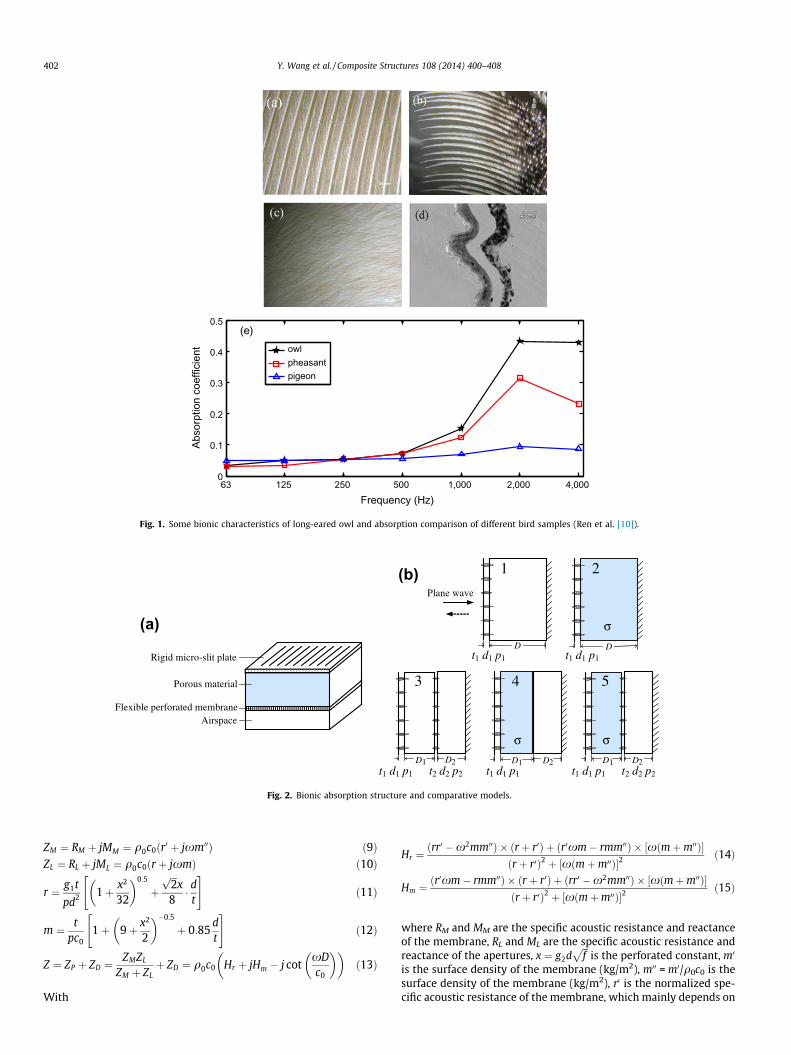
Ren et al. [10] investigated the acoustic performance of thechest and abdominal skin and feather samples of long-eared owl,pheasant and pigeon. Some bionic characteristics of long-earedowl (a. ribbed structure of feather surface, b. micro-slit structureof feather, c. fibrous structure of fluff, d. cavity under the dermallayer of skin) and absorption comparison of different bird samples(e) are displayed in Fig. 1.
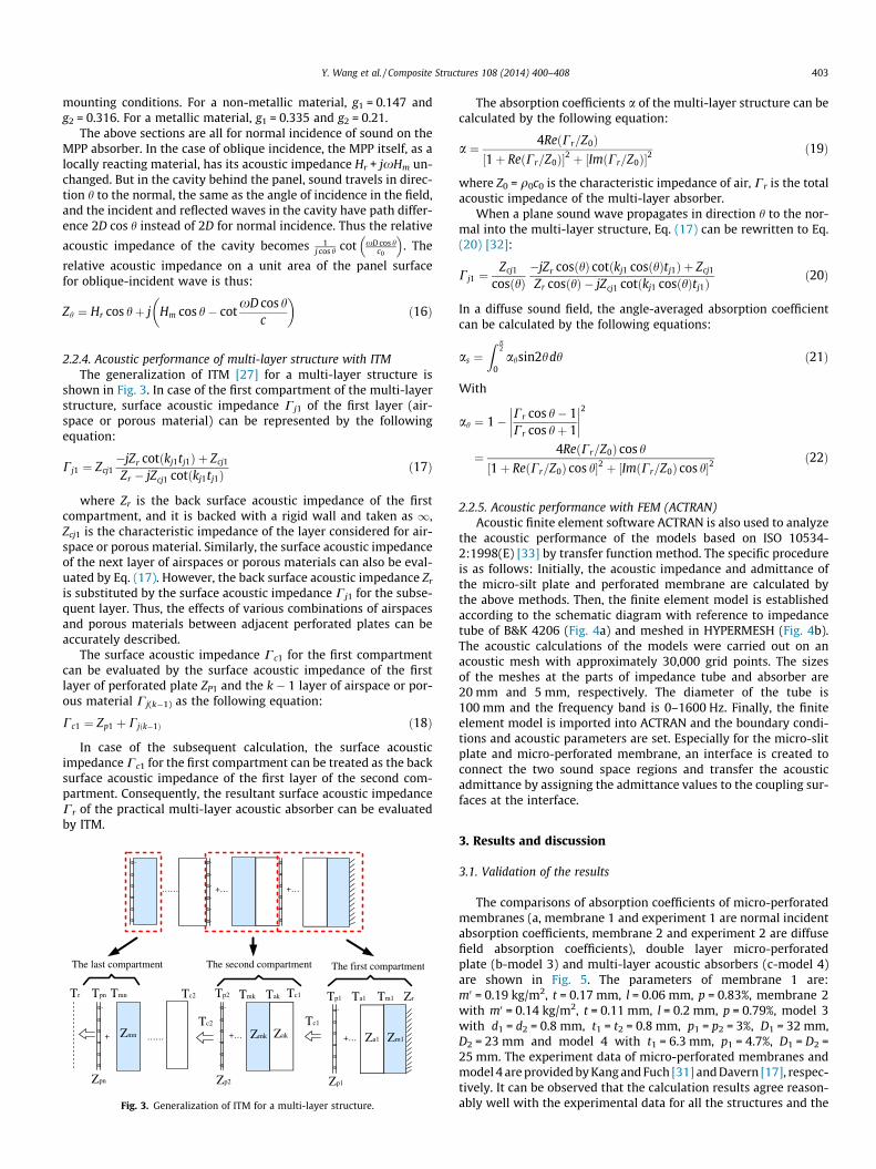
Fig. 1e indicates that the absorption coefficients of owl skin andoverlying feathers are much higher than the other two birds, espe-cially within the frequency range from 1000 Hz to 4000 Hz. In thepresent study, bionic coupling modeling method is used to analyzethe surface noise reduction mechanism based on the absorptioncharacteristics of long-eared owl. The bionic analogies are charac-terized as follows: (1) The covering feather is analogous to rigidmicro-slit plate, (2) The chest fluff is analogous to uniform fiberabsorption material, (3) The dermis layer and subcutaneous cavityare analogous to a sound absorber, which compose of flexible mi-cro-perforated membrane and airspace. The bionic coupling struc-ture (a) and some comparative models (b) are shown in Fig. 2.Fig. 2b is composed of model 1 (a micro-slit plate backed withairspace), model 2 (a micro-slit plate backed with porousmaterial), model 3 (double layer structure of micro-slit plate and
micro-perforated membrane), model 4 (multi-layer structure ofmicro-slit plate, porous material and airspace) and model 5(multi-layer structure of micro-slit plate, porous material, micro-perforated membrane and airspace). The first four are contrastmodels and the fifth is the bionic model.
2.2. Calculation method of acoustic performance
The methods used to analyze the various absorption perfor-mances in the study are discussed in following sections.
2.2.1. Acoustic impedance of rigid micro-silt plateThe calculation of acoustic performance of micro-slit plate is
based on Maa’s micro-silt theory [29] and expresses in the follow-ing equations:
Zp¼q0c0ðrþ jxmÞ¼ 12gtpq0c0
1þ x2
18
� �0:5
þ jxtpc0½1þð25þ2x2Þ�0:5� ð1Þ
ZD¼�jq0c0 �cotxDc0
� �ð2Þ
Z¼ ZpþZD ð3Þ
where x = 2pf, f is the frequency, x ¼ 0:5dffiffiffiffiffiffiffiffiffiffix=l
pis the perforated
constant, j ¼ffiffiffiffiffiffiffi�1p
, t, d, p are the thickness, width of micro-slit andporosity of micro-slit plate, respectively. g, q0, c0 are the kinematicviscosity of air, density of air and sound speed, D is the thickness ofthe airspace behind the micro-slit plate, ZP, ZD and Z are the imped-ances of micro-slit plate, airspace and micro-slit absorber.
In the case of oblique incidence, when a sound wave is incidentat an angle h to the normal, the relative acoustic impedance of the
cavity with thickness of D becomes 1j cos h cot xD cos h
c0
� �. If the incident
direction of sound wave is vertical with the length direction of mi-cro-slit, the normalized specific acoustic impedance is thus as Eq.(4). If it is parallel with the length direction of micro-slit, the nor-malized specific acoustic impedance is thus as Eq. (5):
Zh ¼ r cos hþ jxm cos h� j cotxD cos h
c0
� �ð4Þ
Zh ¼ r þ jxm� j cotxD cos h
c0
� �ð5Þ
2.2.2. Acoustic impedance of porous materialConsidering the accuracy and simplicity, Delany–Bazley–Miki
[30] model is proposed to evaluate the wavenumber k and charac-teristic impedance Zc:
Zc ¼ q0c0 1þ 5:50 103 fr
� ��0:632
� j8:43 103 fr
� ��0:632" #
ð6Þ
k ¼ xc0
1þ 7:81 103 fr
� ��0:618
� j11:41 103 fr
� ��0:618" #
ð7Þ
For 0:01 <fr< 1:00 ð8Þ
where r is the resistivity of porous material.
2.2.3. Acoustic impedance of micro-perforated membraneA micro-perforated membrane backed by airspace makes a res-
onant system, which can be obtained using the impedance type ofelectro-acoustic analogy. Basically, the resonant system containsthe mass-resistance element in series with the cavity reactanceof the airspace [31]. The acoustic performance can be representedby the following equations:
63 125 250 500 1,000 2,000 4,0000
0.1
0.2
0.3
0.4
0.5
Frequency (Hz)
Abso
rptio
n co
effic
ient owl
pheasantpigeon
(e)
Fig. 1. Some bionic characteristics of long-eared owl and absorption comparison of different bird samples (Ren et al. [10]).
Plane wave
D
D1 D2
D
D1 D2 D1 D2
(b) 1 2
3 4 5
t1 d1 p1
σ
σ σ
t1 d1 p1
t1 d1 p1 t1 d1 p1 t1 d1 p1 t2 d2 p2t2 d2 p2
Rigid micro-slit plate
Porous material
Flexible perforated membraneAirspace
(a)
Fig. 2. Bionic absorption structure and comparative models.
402 Y. Wang et al. / Composite Structures 108 (2014) 400–408
ZM ¼ RM þ jMM ¼ q0c0ðr0 þ jxm00Þ ð9ÞZL ¼ RL þ jML ¼ q0c0ðr þ jxmÞ ð10Þ
r ¼ g1t
pd2 1þ x2
32
� �0:5
þffiffiffi2p
x8� d
t
" #ð11Þ
m ¼ tpc0
1þ 9þ x2
2
� ��0:5
þ 0:85dt
" #ð12Þ
Z ¼ ZP þ ZD ¼ZMZL
ZM þ ZLþ ZD ¼ q0c0 Hr þ jHm � j cot
xDc0
� �� �ð13Þ
With
Hr ¼ðrr0 �x2mm00Þ � ðr þ r0Þ þ ðr0xm� rmm00Þ � ½xðmþm00Þ�
ðr þ r0Þ2 þ ½xðmþm00Þ�2ð14Þ
Hm ¼ðr0xm� rmm00Þ � ðr þ r0Þ þ ðrr0 �x2mm00Þ � ½xðmþm00Þ�
ðr þ r0Þ2 þ ½xðmþm00Þ�2ð15Þ
where RM and MM are the specific acoustic resistance and reactanceof the membrane, RL and ML are the specific acoustic resistance andreactance of the apertures, x ¼ g2d
ffiffiffif
pis the perforated constant, m0
is the surface density of the membrane (kg/m2), m00 = m0/q0c0 is thesurface density of the membrane (kg/m2), r0 is the normalized spe-cific acoustic resistance of the membrane, which mainly depends on
Y. Wang et al. / Composite Structures 108 (2014) 400–408 403
mounting conditions. For a non-metallic material, g1 = 0.147 andg2 = 0.316. For a metallic material, g1 = 0.335 and g2 = 0.21.
The above sections are all for normal incidence of sound on theMPP absorber. In the case of oblique incidence, the MPP itself, as alocally reacting material, has its acoustic impedance Hr + jxHm un-changed. But in the cavity behind the panel, sound travels in direc-tion h to the normal, the same as the angle of incidence in the field,and the incident and reflected waves in the cavity have path differ-ence 2D cos h instead of 2D for normal incidence. Thus the relative
acoustic impedance of the cavity becomes 1j cos h cot xD cos h
c0
� �. The
relative acoustic impedance on a unit area of the panel surfacefor oblique-incident wave is thus:
Zh ¼ Hr cos hþ j Hm cos h� cotxD cos h
c
� �ð16Þ
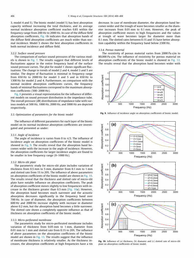
2.2.4. Acoustic performance of multi-layer structure with ITMThe generalization of ITM [27] for a multi-layer structure is
shown in Fig. 3. In case of the first compartment of the multi-layerstructure, surface acoustic impedance Cj1 of the first layer (air-space or porous material) can be represented by the followingequation:
Cj1 ¼ Zcj1�jZr cotðkj1tj1Þ þ Zcj1
Zr � jZcj1 cotðkj1tj1Þð17Þ
where Zr is the back surface acoustic impedance of the firstcompartment, and it is backed with a rigid wall and taken as 1,Zcj1 is the characteristic impedance of the layer considered for air-space or porous material. Similarly, the surface acoustic impedanceof the next layer of airspaces or porous materials can also be eval-uated by Eq. (17). However, the back surface acoustic impedance Zr
is substituted by the surface acoustic impedance Cj1 for the subse-quent layer. Thus, the effects of various combinations of airspacesand porous materials between adjacent perforated plates can beaccurately described.
The surface acoustic impedance Cc1 for the first compartmentcan be evaluated by the surface acoustic impedance of the firstlayer of perforated plate ZP1 and the k � 1 layer of airspace or por-ous material Cj(k�1) as the following equation:
Cc1 ¼ Zp1 þ Cjðk�1Þ ð18Þ
In case of the subsequent calculation, the surface acousticimpedance Cc1 for the first compartment can be treated as the backsurface acoustic impedance of the first layer of the second com-partment. Consequently, the resultant surface acoustic impedanceCr of the practical multi-layer acoustic absorber can be evaluatedby ITM.
Fig. 3. Generalization of ITM for a multi-layer structure.
The absorption coefficients a of the multi-layer structure can becalculated by the following equation:
a ¼ 4ReðCr=Z0Þ½1þ ReðCr=Z0Þ�2 þ ½ImðCr=Z0Þ�2
ð19Þ
where Z0 = q0c0 is the characteristic impedance of air, Cr is the totalacoustic impedance of the multi-layer absorber.
When a plane sound wave propagates in direction h to the nor-mal into the multi-layer structure, Eq. (17) can be rewritten to Eq.(20) [32]:
Cj1 ¼Zcj1
cosðhÞ�jZr cosðhÞ cotðkj1 cosðhÞtj1Þ þ Zcj1
Zr cosðhÞ � jZcj1 cotðkj1 cosðhÞtj1Þð20Þ
In a diffuse sound field, the angle-averaged absorption coefficientcan be calculated by the following equations:
as ¼Z p
2
0ahsin2hdh ð21Þ
With
ah ¼ 1� Cr cos h� 1Cr cos hþ 1
��������2
¼ 4ReðCr=Z0Þ cos h
½1þ ReðCr=Z0Þ cos h�2 þ ½ImðCr=Z0Þ cos h�2ð22Þ
2.2.5. Acoustic performance with FEM (ACTRAN)Acoustic finite element software ACTRAN is also used to analyze
the acoustic performance of the models based on ISO 10534-2:1998(E) [33] by transfer function method. The specific procedureis as follows: Initially, the acoustic impedance and admittance ofthe micro-silt plate and perforated membrane are calculated bythe above methods. Then, the finite element model is establishedaccording to the schematic diagram with reference to impedancetube of B&K 4206 (Fig. 4a) and meshed in HYPERMESH (Fig. 4b).The acoustic calculations of the models were carried out on anacoustic mesh with approximately 30,000 grid points. The sizesof the meshes at the parts of impedance tube and absorber are20 mm and 5 mm, respectively. The diameter of the tube is100 mm and the frequency band is 0–1600 Hz. Finally, the finiteelement model is imported into ACTRAN and the boundary condi-tions and acoustic parameters are set. Especially for the micro-slitplate and micro-perforated membrane, an interface is created toconnect the two sound space regions and transfer the acousticadmittance by assigning the admittance values to the coupling sur-faces at the interface.
3. Results and discussion
3.1. Validation of the results
The comparisons of absorption coefficients of micro-perforatedmembranes (a, membrane 1 and experiment 1 are normal incidentabsorption coefficients, membrane 2 and experiment 2 are diffusefield absorption coefficients), double layer micro-perforatedplate (b-model 3) and multi-layer acoustic absorbers (c-model 4)are shown in Fig. 5. The parameters of membrane 1 are:m0 = 0.19 kg/m2, t = 0.17 mm, l = 0.06 mm, p = 0.83%, membrane 2with m0 = 0.14 kg/m2, t = 0.11 mm, l = 0.2 mm, p = 0.79%, model 3with d1 = d2 = 0.8 mm, t1 = t2 = 0.8 mm, p1 = p2 = 3%, D1 = 32 mm,D2 = 23 mm and model 4 with t1 = 6.3 mm, p1 = 4.7%, D1 = D2 =25 mm. The experiment data of micro-perforated membranes andmodel 4 are provided by Kang and Fuch [31] and Davern [17], respec-tively. It can be observed that the calculation results agree reason-ably well with the experimental data for all the structures and the

Plane wave
Microphone
Boundary condition Mocro-slit panel
Micro-perforated panelImpedance tube
Porous materials Cavity
(a)
(b)
Fig. 4. Schematic diagram of FEM (a) and grid distribution (b) of bionic model.
63 125 250 500 1000 2000 4000 80000
0.2
0.4
0.6
0.8
1
Frequency (Hz)
Abso
rptio
n co
effic
ient
Membrane 1Experiment 1Membrane 2Experiment 2
(a)
0 200 400 600 800 1000 1200 1400 16000
0.2
0.4
0.6
0.8
1
Frequency (Hz)
Abso
rptio
n co
effic
ient ITM
ACTRANExperiment
(b)
0 500 1000 1500 20000
0.2
0.4
0.6
0.8
1
Frequency (Hz)
Abso
rptio
n co
effic
ient ITM
ACTRANExperiment
(c)
Fig. 5. Absorption coefficients of different structures.
0 500 1000 1500 2000 2500 30000
0.2
0.4
0.6
0.8
1
Frequency (Hz)
Abso
rptio
n co
effic
ient
model 1model 2model 3model 4model 5
(a)
0 500 1000 1500 2000 2500 30000
0.2
0.4
0.6
0.8
1
Frequency (Hz)
Abso
rptio
n co
effic
ient
model 1model 2model 3model 4model 5
(b)
Fig. 6. Normal incidence (a) and diffuse field (b) absorption coefficients of variousmodels.
0 500 1000 1500 2000 2500 3000130
140
150
160
170
180
Frequency (Hz)
Soun
d pr
essu
re (d
B)
model 1model 2model 3model 4model 5
Fig. 7. Surface sound pressure (dB) of the various models.
404 Y. Wang et al. / Composite Structures 108 (2014) 400–408

Y. Wang et al. / Composite Structures 108 (2014) 400–408 405
results of ITM and ACTRAN are almost the same. Thus, the methodsdescribed in the above section are validated for the study of acousticcharacteristics of the models.
3.2. Acoustic performance of the bionic model
The parameters of the bionic model are determined accordingto the size of bionic characteristics of long-eared owl. Withreference to Fig. 2b, the various parameters considered are:t1 = 2 mm, d1 = 0.5 mm, p1 = 5%, t2 = 0.2 mm, d2 = 0.06 mm,
Fig. 8. Sound pressure (dB) dist
p2 = 0.83%, m0= 0.19 kg/m2, D1 = 25 mm, r = 10,000 Pa s/m, D2 =
25 mm and D = D1 + D2 = 50 mm.
3.2.1. Sound absorption coefficientsThe comparison of normal incidence (a) and diffuse field
absorption coefficients (b) of the various models are shown inFig. 6. Fig. 6a suggests that the micro-slit plate filled with porousmaterial considerably improves the normal incidence absorptioncoefficients (model 1 and 2, model 1 and 4). The double layer mi-cro-perforated plate broadens the absorption band (model 1 and
ribution of various models.
0 500 1000 1500 2000 2500 30000
0.2
0.4
0.6
0.8
1
Frequency (Hz)
Abso
rptio
n co
effic
ient
θ=0θ=π/10θ=π/8θ=π/6θ=π/4θ=π/3
Fig. 9. Influence of incidence angle on absorption coefficients of bionic model.
0 500 1000 1500 2000 2500 30000
0.2
0.4
0.6
0.8
1
Frequency (Hz)
Abso
rptio
n co
effic
ient
t1=0.5mmt1=1mmt1=1.5mmt1=2mmt1=3mmt1=5mm
(a)
0 500 1000 1500 2000 2500 30000
0.2
0.4
0.6
0.8
1
Frequency (Hz)
Abso
rptio
n co
effic
ient
d1=0.1mmd1=0.2mmd1=0.3mmd1=0.5mmd1=0.8mmd1=1mm
(b)
0 500 1000 1500 2000 2500 30000
0.2
0.4
0.6
0.8
1
Frequency (Hz)
Abso
rptio
n co
effic
ient
p1=1%p1=2%p1=5%p1=8%p1=10%p1=15%p1=20%
(c)
Fig. 10. Influence of (a) thickness, (b) diamater and (c) slotted rate of micro-slitplate on absorption coefficients of bionic model.
406 Y. Wang et al. / Composite Structures 108 (2014) 400–408
3, model 4 and 5). The bionic model (model 5) has best absorptioncapacity without increasing the total thickness, and its averagenormal incidence absorption coefficient reaches 0.85 within thefrequency range from 200 Hz to 2000 Hz. In case of the diffuse fieldabsorption coefficients, Fig. 6b indicates that absorption bands ofthe diffuse field absorption coefficients are much wider than nor-mal incidence. Model 5 shows the best absorption coefficients inboth normal incidence and diffuse field.
3.2.2. Surface sound pressureThe comparison of surface sound pressures of the various mod-
els is shown in Fig. 7. The results suggest that different levels offluctuations appear in the entire frequency band of the surfacesound pressure curves. The plot for model 1 shows significant fluc-tuations. The change in trends of model 2 and 4, model 3 and 5 aresimilar. The degree of fluctuation is minimal in frequency rangefrom 650 Hz to 2000 Hz for model 3 and 5 and in 650 Hz to1300 Hz for model 2 and 4. Furthermore, on comparison with thenormal incident absorption coefficients curves, the frequencybands of minimal fluctuations correspond to the maximum absorp-tion coefficients (500–2000 Hz).
Fig. 8 presents a visual representation for the influence of differ-ent models on sound pressure distribution in the impedance tube.The overall pressure (dB) distributions of impedance tube with var-ious models at 500 Hz, 1000 Hz, 2000 Hz, and 3000 Hz are depictedrespectively.
3.3. Optimization of parameters for the bionic model
The influence of different parameters for each layer of the bionicmodel on its normal incidence absorption coefficients are investi-gated and presented as under:
3.3.1. Angle of incidenceThe angle of incidence is varies from 0 to p/3. The influence of
incidence angle on absorption coefficients of the bionic model isshowed in Fig. 9. The results reveal that the absorption band be-comes wider with the increase in the angle of incidence. However,the absorption coefficients for larger incidence angles are found tobe smaller in low frequency range (0–1000 Hz).
3.3.2. Micro-slit plateThe parametric study for micro-slit plate includes variation of
thickness from 0.5 mm to 5 mm, diameter from 0.1 mm to 1 mmand slotted rate from 1% to 20%. The influence of above parameterson absorption coefficients of the bionic model are shown in Fig. 10.The results reveal that the thickness and slotted rate of micro-slitplate have notable influence on absorption coefficients. The peakof absorption coefficient moves slightly to low frequencies with in-crease in the thickness greater than 0.5 mm (Fig. 10a). However,the absorption band becomes much narrower and the acousticabsorption decreases significantly in the frequency band over700 Hz. In case of diameter, the absorption coefficients between600 Hz and 2000 Hz increase slightly with increase in diameterabove 0.2 mm, but the absorption band becomes a little narrower.The slotted rate shows a completely opposite influence as that ofthickness on absorption coefficients of the bionic model.
3.3.3. Micro-perforated membraneThe parametric study for micro-perforated membrane includes
variation of thickness from 0.05 mm to 1 mm, diameter from0.01 mm to 1 mm and slotted rate from 0.1% to 20%. The influenceof above parameters on the absorption coefficients of the bionicmodel are shown in Fig. 11. The results suggest that the influenceof membrane thickness is relatively smaller. As the thickness in-creases, the absorption coefficients at high frequencies have a tin
decrease. In case of membrane diameter, the absorption band be-comes wider and the trough of wave becomes smaller as the diam-eter increases from 0.01 mm to 0.1 mm. However, the peak ofabsorption coefficient moves to high frequencies and the valuesat trough of wave becomes larger for diameter more than0.1 mm. The slotted rates between 0.1% and 1% have better absorp-tion capability within the frequency band below 2300 Hz.
3.3.4. Porous materialThe resistivity of porous material varies from 2000 Pa s/m to
80,000 Pa s/m. The influence of resistivity for porous material onabsorption coefficients of the bionic model is showed in Fig. 12.The results reveal that the absorption band becomes wider with

0 500 1000 1500 2000 2500 30000
0.2
0.4
0.6
0.8
1
Frequency (Hz)
Abso
rptio
n co
effic
ient
t2=0.05mmt2=0.1mmt2=0.15mmt2=0.2mmt2=0.5mmt2=0.08mmt2=1mm
(a)
0 500 1000 1500 2000 2500 30000
0.2
0.4
0.6
0.8
1
Frequency (Hz)
Abso
rptio
n co
effic
ient
d2=0.01mmd2=0.05mmd2=0.08mmd2=0.1mmd2=0.2mmd2=0.5mmd2=1mm
(b)
0 500 1000 1500 2000 2500 30000
0.2
0.4
0.6
0.8
1
Frequency (Hz)
Abso
rptio
n co
effic
ient
p2=0.1%p2=0.5%p2=1%p2=5%p2=10%p2=15%p2=20%
(c)
Fig. 11. Influence of (a) thickness, (b) diamater and (c) slotted rate of micro-perforated membrane on absorption coefficients of bionic model.
0 500 1000 1500 2000 2500 30000
0.2
0.4
0.6
0.8
1
Frequency (Hz)
Abso
rptio
n co
effic
ient
σ =2000σ =5000σ =10000σ =20000σ =30000σ =50000σ =80000
Fig. 12. Influence of resistivity of porous material on absorption coefficients ofbionic model.
0 500 1000 1500 2000 2500 30000
0.2
0.4
0.6
0.8
1
Frequency (Hz)
Abso
rptio
n co
effic
ient
D1+D2=10mm+40mmD1+D2=15mm+35mmD1+D2=20mm+30mmD1+D2=25mm+25mmD1+D2=30mm+20mmD1+D2=35mm+15mmD1+D2=40mm+10mm
Fig. 13. Influence of combination of porous material and airspace thickness onabsorption coefficients of bionic model.
Y. Wang et al. / Composite Structures 108 (2014) 400–408 407
the increase in resistivity. However, the initial peak decreases sig-nificantly at low frequencies.
3.3.5. Combination of porous material and airspace thicknessThe total thickness of porous material and airspace is constant
at 50 mm. The thickness of porous material varies from 10 mmto 40 mm. The influence of various thickness combinations for por-ous material and airspace on absorption coefficients is presented inFig. 13. The results demonstrate that the second peak of absorptioncoefficient moves to lower frequencies with the increase of porousmaterial thickness. The value at trough of wave increases until the
plot completely flattens out. However, the airspace thickness influ-ences the absorption coefficient in the opposite manner.
4. Conclusions
In this study, a bionic coupling multi-layer structure is devel-oped based on the biomimetic method. The acoustic performanceincluding impedance, sound pressure and absorption coefficientsas well as parametric influence of each layer are investigated byimpedance transfer method and finite element method (ACTRAN).The bionic model shows excellent absorption performance. Itsaverage normal incidence absorption coefficient is found to be0.778 within the frequency range from 0 to 2000 Hz while 0.85from 200 Hz to 2000 Hz. Based on the results and discussion, theoptimal parameters are determined as t1 = 1 mm, d1 = 0.5 mm,p1 = 15%, t2 = 0.1 mm, d2 = 0.05 mm, p2 = 1%, D1 = 20 mm,r = 20,000 Pa s/m, and D2 = 30 mm. The significant improvementof absorption coefficients at low frequencies can be attributed tothe Helmholtz effects of the micro-silt plate and flexible micro-perforated membrane, and the combination with porous materials,which leads to even better absorption performance in broadband.The study emphasizes that further investigations on the bioniccoupling multi-layer structure can provide better absorbing sys-tem for practical applications.
Acknowledgments
All support is greatly acknowledged and appreciated, especiallythe constructive discussion and criticism from colleagues. Thanksare due to the Joint Funds of the National Natural Science Founda-tion of China (Grant No. U1134109), the Specialized Research Fundfor the Doctoral Program of Higher Education of China (Grant No.20110061120048), and the projects of National Natural ScienceFoundation of China (Grant Nos. 31071928, 51106062 and51206058), for allowing to undertake the project and the financialsupport extended.
References
[1] Xue CY, Chen S, Zhang WD, Zhang BZ, Zhang GJ, Qiao H. Design, fabrication, andpreliminary characterization of a novel MEMs bionic vector hydrophone.Microelectron J 2007;38:1021–6.
[2] Han ZW, Niu SC, Shang CH, Liu ZN, Ren LQ. Light trapping structures in wingscales of butterfly Trogonoptera brookiana. Nanoscale 2012;4:2879–83.
[3] Ren LQ, Tong J, Li JQ, Chen BC. Swsoil and water: soil adhesion and biomimeticsof soil-engaging components: a review. J Agric Eng Res 2001;79:239–63.
[4] Sun TL, Feng L, Gao XF, Jiang L. Bioinspired surfaces with special wettability.Acc Chem Res 2005;38:644–52.
[5] Feng L, Li HS, Li YS, Li HJ, Zhang LJ, Zhai J. Superhydrophobic surfaces: fromnatural to artificial. Adv Mater 2002;14:1857–60.
[6] Graham RR. The silent flight of owls. J Roy Aeronaut Soc 1934;38:837–43.[7] Kroeger RA, Grushka HD, Helvey TC. Low speed aero-dynamics for ultra-quiet
flight. Technical report AFFDL-TR-71-75. Air Force Flight Dynamics Lab,Wright-Patterson Air Force Base, Ohio, USA; 1971.

408 Y. Wang et al. / Composite Structures 108 (2014) 400–408
[8] Lilley GM. A study of the silent flight of the owl. AIAA Paper; 1998. p. 2004–186.
[9] Lilley GM. A quest for quiet commercial passenger transport aircraft for take-off and landing. AIAA Paper; 2004. p. 2922.
[10] Sun SM, Ren LQ, Xun CY. Research on coupling sound absorption property ofowl skin and feather. Noise Vib Contr 2008;6:119–23 [in Chinese].
[11] Liu TS, Kuykendoll K, Rhew R, Jones S. Avian wings. AIAA Paper; 2004. p. AIAA-2004–2186.
[12] Ahuja KK, Stevens JC. Recent advances in active noise control. In: Proceedingsof the 13th AIAA, Aeroacoustics Conference, Tallahassee, FL; 1990.
[13] Miccoli G, Concilio A. Recent advances in noise and vibration active control bymeans of piezoelectric transducers. In: Proceedings of the 3rd internationalcongress on air- and structure-borne sound and vibration, Montreal. Canada;1994. p. 1377–84.
[14] Ross C. Current developments and future trends in active noise control. NoiseVib Contr Worldwide 1989:171–3.
[15] Tichy J. Current and future issues of active noise control. J Acoust Soc Jpn (E)1991;12:255–62.
[16] Hirsch SM, Jayachandran V, Sun JQ. Structural-acoustic control for quieteraircraft interior-smart trim technology. Compos Struct 1998;42:189–202.
[17] Davern WA. Perforated facings backed with porous materials as soundabsorbers – an experimental study. Appl Acoust 1977;10:85–112.
[18] Dunnand IP, Davern WA. Calculation of acoustic impedance of multilayerabsorbers. Appl Acoust 1986;19:321–34.
[19] Jinkyo L, George W, Swenson J. Compact sound absorbers for low frequencies.Noise Contr l Eng J 1992;38:109–17.
[20] Chen WH, Lee FC, Chiang DM. On the acoustic absorption of porous materialswith different surface shapes and perforated plates. J Sound Vib2000;237:337–55.
[21] Buitrago BL, Santiuste C, Sánchez-Sáez S, et al. Modelling of compositesandwich structures with honeycomb core subjected to high-velocity impact.Compos Struct 2010;92:2090–6.
[22] Koutsawa Y, Azoti WL, Belouettar S, et al. Loss behavior of viscoelasticsandwich structures: a statistical-continuum multi-scale approach. ComposStruct 2012;94:1391–7.
[23] Wang SC, Deng ZX, Shen WD. Sound transmission loss characteristics ofunbounded orthotropic sandwich panels in bending vibration consideringtransverse shear deformation. Compos Struct 2010;92:2885–9.
[24] Larbi W, Deü JF, Ohayon R. Finite element formulation of smart piezoelectriccomposite plates coupled with acoustic fluid. Compos Struct 2012;94:501–9.
[25] Lin L, Wang ZM, Jiang ZX. Effect of sound-absorbing material on a micro-perforated absorbing construction. ACTA Acoust 2010;4:385–92.
[26] Lee DH, Kwon YP. Estimation of the absorption performance of multiple layerperforated panel systems by transfer matrix method. J Sound Vib2004;278:847–60.
[27] Lee FC, Chen WH. Acoustic transmission analysis of multi-layer absorbers. JSound Vib 2001;248:621–34.
[28] Zhao XD, Hu P, Sun P. The comparative analyses of the calculation methods forabsorptivity of multilayer micro-perforated panel absorbers. Appl Acoust2012;3:6.
[29] Maa DY. Theory of microslit absorbers. Acta Acust 2000;25:481–5.[30] Miki Y. Acoustical properties of porous materials – modifications of Delany–
Bazley models. J Acoust Soc Jpn (E) 1990;11:19–24.[31] Kang J, Fuchs HV. Predicting the absorption of open weave textiles and micro-
perforated membranes backed by an air space. J Sound Vib 1999;220:905–20.[32] Allard JF, Atalla N. Propagation of sound in porous media: modelling sound
absorbing materials. Elsevier; 2009.[33] ISO 10534-2. Acoustics-determination of sound absorption coefficient and
impedance in impedances tubes – Part 2: Transfer-function method.International Organization for Standardization; 1998.