south african national roads agency limited · 2.44 commissioning ... 222 16.6 commissioning ......
TRANSCRIPT

PROCUREMENT OF A NATIONAL INTELLIGENT TRANSPORT SYSTEM AND INTEGRATED SUPPORTING SYSTEMS SOFTWARE AND THE DEPLOYMENT THEREOF IN GAUTENG, KWAZULU-NATAL AND THE WESTERN CAPE
STANDARD SPECIFICATION FOR ELECTRONIC WORKS
JUNE 2010 VOLUME 2 BOOK 4b
SOUTH AFRICAN NATIONAL ROADS AGENCY LIMITED
Registration No: 1998/009584/06
THE REGIONAL MANAGER
NORTHERN REGION
SOUTH AFRICAN NATIONAL ROADS AGENCY LIMITED
38 IDA STREET
MENLO PARK
PRETORIA
SOUTH AFRICA
0081

- ii -
VOLUME 2 BOOK 4b: STANDARD SPECIFICATION FOR ELECTRONIC WORKS

- iii -
VOLUME 2 BOOK 4b: STANDARD SPECIFICATION FOR ELECTRONIC WORKS
TABLE OF CONTENT
PART 3 ELECTRONIC EQUIPMENT AND DESIGN .................................................................................................... 7
SECTION 1 INFORMATION AND COMMUNICATION TECHNOLOGY SPECIFICATIONS .............................................. 8
1.1 SCOPE .................................................................................................................................................................. 9
1.2 STANDARDS ........................................................................................................................................................ 9 1.3 NETWORK CABLING .......................................................................................................................................... 11
1.4 NETWORK AND COMMUNICATION EQUIPMENT .............................................................................................. 18
1.5 SERVER AND STORAGE HARDWARE .................................................................................................................. 22
1.6 MAN MACHINE INTERFACE HARDWARE (MMI) ................................................................................................ 32 1.7 SOFTWARE ........................................................................................................................................................ 36
1.8 ENVIRONMENT AND ENCLOSURE HARDWARE ................................................................................................. 47
1.9 PLANNING ......................................................................................................................................................... 51 1.10 QUALITY PLAN ................................................................................................................................................... 51
1.11 DOCUMENTATION ............................................................................................................................................ 55
SECTION 2 SUPERVISORY CONTROL AND DATA ACQUISITION (SCADA) ................................................................57
2.1 SCOPE ................................................................................................................................................................ 58 2.2 ELECTRICAL FENCE ............................................................................................................................................ 61
2.3 GSM MODULE ................................................................................................................................................... 61
2.4 OVER TEMP ....................................................................................................................................................... 61
2.5 CCTV .................................................................................................................................................................. 61 2.6 SECURITY SYSTEM ............................................................................................................................................. 62
2.7 VOIP COMMUNICATION REMOTE SITES ........................................................................................................... 63
2.8 VOIP COMMUNICATION SYSTEM SATELLITE CENTRE........................................................................................ 63 2.9 VOIP COMMUNICATION SYSTEM TOLL PLAZA .................................................................................................. 63
2.10 ACCESS CONTROL SYSTEM ................................................................................................................................ 64
2.11 UPS .................................................................................................................................................................... 66
2.12 POWER QUALITY AND SITE INFORMATION ....................................................................................................... 66 2.13 GENERATOR ...................................................................................................................................................... 67
2.14 GENERAL ........................................................................................................................................................... 68
2.15 EQUIPMENT RECORD SYSTEM (ERS) ................................................................................................................. 70
2.16 COMPUTERISED MAINTENANCE MANAGEMENT SYSTEM (CMMS) .................................................................. 70 2.17 WORKSTATION .................................................................................................................................................. 71
2.18 SERVER .............................................................................................................................................................. 71
2.19 SOFTWARE REQUIREMENTS ............................................................................................................................. 71 2.20 SQL DATABASE .................................................................................................................................................. 72
2.21 SOFTWARE LICENCE .......................................................................................................................................... 72
2.22 DATA COMMUNICATION .................................................................................................................................. 72
2.23 NETWORKING ................................................................................................................................................... 72 2.24 NETWORK SECURITY ......................................................................................................................................... 73
2.25 .NET FRAMEWORK ............................................................................................................................................ 73
2.26 NOTIFICATION ................................................................................................................................................... 73 2.27 REMOTE ACCESS ............................................................................................................................................... 73
2.28 OTHER CONNECTIVITY ...................................................................................................................................... 73
2.29 INTEGRATION AND INTEROPERABILITY ............................................................................................................. 74
2.30 EXPANDABILITY ................................................................................................................................................. 74 2.31 HUMAN MACHINE INTERFACE (HMI) ................................................................................................................ 74
2.32 REPORTING ....................................................................................................................................................... 78
2.33 OBJECT ORIENTED GRAPHICS ............................................................................................................................ 80
2.34 FAULT TOLERANT .............................................................................................................................................. 81 2.35 INTERFACE ........................................................................................................................................................ 81
2.36 REMOTE OPERATION ........................................................................................................................................ 81
2.37 RECOVERY PACK ................................................................................................................................................ 82 2.38 AUDIT AND VERIFICATION................................................................................................................................. 82
2.39 SUPPORT ........................................................................................................................................................... 82
2.40 GUARANTEE ...................................................................................................................................................... 82

- iv -
VOLUME 2 BOOK 4b: STANDARD SPECIFICATION FOR ELECTRONIC WORKS
2.41 INDUSTRIAL STANDARDS .................................................................................................................................. 82
2.42 LABELLING ......................................................................................................................................................... 82 2.43 OPERATION ....................................................................................................................................................... 82
2.44 COMMISSIONING .............................................................................................................................................. 82
2.45 DEFINE THREATS, RISKS AND CONSEQUENCES ................................................................................................. 83 2.46 SPECIAL TESTING NEEDS ................................................................................................................................... 83
2.47 DOCUMENT COMPLIANCE ................................................................................................................................ 83
2.48 INSPECTIONS & TESTING ................................................................................................................................... 84
2.49 DRAWINGS AND INFORMATION ....................................................................................................................... 85 2.50 SCADA DATA AND COMPLIANCE SHEET ............................................................................................................ 86
SECTION 3 SECURITY AND ACCESS CONTROL REQUIREMENTS .............................................................................88
3.1 INTRODUCTION ................................................................................................................................................. 89
3.2 FACILITY SECURITY REQUIREMENTS.................................................................................................................. 91 3.3 SECURITY PHILOSOPHY ..................................................................................................................................... 93
3.4 TECHNICAL SPECIFICATION ............................................................................................................................... 97
3.5 SECURITY ALARM SYSTEM ............................................................................................................................... 102 3.6 INTERCOMMUNICATIONS SYSTEM ................................................................................................................. 107
3.7 SYSTEM POWER SUPPLIES ............................................................................................................................... 109
3.8 RACKS .............................................................................................................................................................. 110
3.9 SECURITY DATA AND COMPLIANCE SHEET ...................................................................................................... 110
SECTION 4 TOLL PLAZA WARNING BEACON........................................................................................................ 112
4.1 SCOPE .............................................................................................................................................................. 113
4.2 GENERAL ......................................................................................................................................................... 113
4.3 WARNING BEACON DATA AND COMPLIANCE SHEET ...................................................................................... 113
SECTION 5 PHYSICAL SECURITY BARRIERS .......................................................................................................... 115
5.1 VEHICLE BOOMS ............................................................................................................................................. 116
5.2 PERSONNEL TURNSTILES ................................................................................................................................. 117 5.3 MOTORISED DOORS AND GATES ..................................................................................................................... 118
SECTION 6 ROADSIDE FIBRE OPTIC DATA COMMUNICATION SYSTEM ............................................................... 119
6.1 SCOPE .............................................................................................................................................................. 120
6.2 STANDARDS .................................................................................................................................................... 120 6.3 FIBRE OPTIC CABLE .......................................................................................................................................... 120
6.4 FIBRE OPTIC CABLE INSTALLATION .................................................................................................................. 121
6.5 JOINTS/ FUSION SPLICING ............................................................................................................................... 122
6.6 OPTICAL FIBRE CONNECTORS.......................................................................................................................... 123 6.7 INTERFACE EQUIPMENT .................................................................................................................................. 123
6.8 TESTING AND COMMISSIONING ..................................................................................................................... 123
SECTION 7 FIRE DETECTION SYSTEM .................................................................................................................. 125
7.1 SCOPE .............................................................................................................................................................. 126
7.2 STANDARDS .................................................................................................................................................... 126
7.3 GENERAL ......................................................................................................................................................... 126
7.4 SMOKE DETECTORS AND LINE ISOLATORS ...................................................................................................... 127 7.5 BATTERIES/UPS POWER .................................................................................................................................. 127
7.6 MANUAL CALL POINTS .................................................................................................................................... 127
7.7 COMBINED SOUNDER AND STROBE LIGHT ..................................................................................................... 127 7.8 CONTROL PANEL ............................................................................................................................................. 128
SECTION 8 GAS FIRE SUPPRESSION SYSTEM ....................................................................................................... 129
8.1 SCOPE .............................................................................................................................................................. 130
8.2 STANDARDS .................................................................................................................................................... 130 8.3 GENERAL ......................................................................................................................................................... 130
SECTION 9 FIRE TELEPHONE SYSTEM .................................................................................................................. 131
9.1 GENERAL ......................................................................................................................................................... 132

- v -
VOLUME 2 BOOK 4b: STANDARD SPECIFICATION FOR ELECTRONIC WORKS
9.2 OPERATION ..................................................................................................................................................... 132
SECTION 10 WIRELESS DATA COMMUNICATION SYSTEM .................................................................................... 133
10.1 PURPOSE OF INSTALLATION ............................................................................................................................ 134
10.2 SCOPE OF WORK ............................................................................................................................................. 134
10.3 APPLICABLE STANDARDS, APPROVAL AND FREQUENCY BAND ....................................................................... 135 10.4 DISCREPANCIES, CONFLICTS AND AMBIGUITIES ............................................................................................. 135
10.5 IDENTIFICATION .............................................................................................................................................. 135
10.6 INSPECTIONS AND TESTS ................................................................................................................................. 135
10.7 GUARANTEE PERIOD, MAINTENANCE AND SPARES ........................................................................................ 136 10.8 OPERATIONAL AND MAINTENANCE MANUALS .............................................................................................. 136
10.9 TRAINING ........................................................................................................................................................ 136
10.10 POINT - TO – POINT (PTP) LINKS .................................................................................................................. 136
SECTION 11 WIRELESS VOICE SYSTEM .................................................................................................................. 150
11.1 SCOPE .............................................................................................................................................................. 151
11.2 LMR EQUIPMENT DESIGN ............................................................................................................................... 151
11.3 HEALTH AND SAFETY ....................................................................................................................................... 151 11.4 TECHNICAL REQUIREMENTS ........................................................................................................................... 151
11.5 SPECIFICATIONS .............................................................................................................................................. 151
11.6 TECHNICAL REQUIREMENTS FOR RADIO EQUIPMENT .................................................................................... 154
SECTION 12 TELEPHONY AND INTERCOM SYSTEMS ............................................................................................. 157
12.1 TELEPHONY ..................................................................................................................................................... 158
12.2 INTERCOM SYSTEM ......................................................................................................................................... 160
SECTION 13 ROADSIDE VEHICLE COUNTING, DETECTION AND WEIGHING ........................................................... 161
13.1 SCOPE .............................................................................................................................................................. 162 13.2 STANDARDS .................................................................................................................................................... 162
13.3 LOOP DETECTORS ............................................................................................................................................ 162
13.4 AXLE SENSORS ................................................................................................................................................. 167 13.5 WEIGH-IN-MOTION SPECIFICATIONS .............................................................................................................. 168
SECTION 14 ROADSIDE DISPLAY SYSTEM .............................................................................................................. 180
14.1 SCOPE .............................................................................................................................................................. 181
14.2 STANDARDS .................................................................................................................................................... 181 14.3 TRAFFIC LIGHTS ............................................................................................................................................... 181
14.4 VARIABLE MESSAGE ........................................................................................................................................ 194
SECTION 15 CCTV SURVEILLANCE SYSTEM ............................................................................................................ 205
15.1 SCOPE .............................................................................................................................................................. 206 15.2 IDENTIFICATION OBJECTIVE ............................................................................................................................ 206
15.3 CAMERAS ........................................................................................................................................................ 207
15.4 MONITORS ...................................................................................................................................................... 213 15.5 CAMERA MASTS .............................................................................................................................................. 214
15.6 CAMERA CABLE CONNECTIONS....................................................................................................................... 215
15.7 DIGITAL RECORDERS ....................................................................................................................................... 215
15.8 MATRIX SWITCH .............................................................................................................................................. 218 15.9 ESSENTIAL OPERATIONAL REQUIREMENTS ..................................................................................................... 218
SECTION 16 INSPECTIONS, TESTING, COMMISSIONING AND HANDING OVER ...................................................... 220
16.1 PHYSICAL INSPECTION PROCEDURE- ............................................................................................................... 221 16.2 FACTORY INSPECTIONS AND TESTS ................................................................................................................. 221
16.3 TESTING AND OPERATIONAL INSPECTION PROCEDURE OF INSTALLATIONS................................................... 221
16.4 TYPE TESTS, TEST CERTIFICATES AND SPECIALIZED TESTS ............................................................................... 222
16.5 "AS BUILT" DRAWINGS, MAINTENANCE AND OPERATING MANUALS ............................................................ 222 16.6 COMMISSIONING ............................................................................................................................................ 223
16.7 DOCUMENTATION .......................................................................................................................................... 223

- vi -
VOLUME 2 BOOK 4b: STANDARD SPECIFICATION FOR ELECTRONIC WORKS
List of Tables
TABLE 2-1: SCADA DATA AND COMPLIANCE SHEET .................................................................................................... 86
TABLE 3-1: SECURITY DATA AND COMPLIANCE SHEET .............................................................................................. 110
TABLE 4-1: WARNING BEACON DATA AND COMPLIANCE SHEET .............................................................................. 113 TABLE 6-1: GEOMETRIC CHARACTERISTICS ............................................................................................................... 120
TABLE 10-1: MEDIUM SPEED LINK RADIO SPECIFICATIONS......................................................................................... 139
TABLE 10-2: HIGH SPEED LINK RADIO SPECIFICATIONS ............................................................................................... 140
TABLE 10-3: LAN/WAN ACCESS POINT SPECIFICATIONS ............................................................................................. 141 TABLE 10-4: MICROWAVE/ISM BAND ANTENNA SPECIFICATIONS ............................................................................. 142
TABLE 10-5: SOLID PARABOLIC ANTENNA SPECIFICATIONS ........................................................................................ 142
TABLE 10-6: SOLID PARABOLIC ANTENNA SPECIFICATIONS ........................................................................................ 143
TABLE 13-1: LOOP DETECTOR SPECIFICATIONS ........................................................................................................... 163 TABLE 13.5-1: VIOLATION RULES ............................................................................................................................... 172
TABLE 14.4-1: LEGIBILITY/SIGHT DISTANCES REQUIRED FOR LATERALLY OFFSET VMS.............................................. 195
List of Figures
FIGURE 2-1: SCADA SYSTEM FUNCTIONALITY ............................................................................................................... 58
FIGURE 2-2: GENERAL SCADA ARCHITECTURE .............................................................................................................. 59 FIGURE 2-3: SCADA SYSTEM BASIC PERIPHERAL LAYOUT ............................................................................................. 60
FIGURE 2-4: HMI (DROP DOWN MENU) ........................................................................................................................ 76
FIGURE 2-5: SCADA SYSTEM EVENT NOTIFICATION FLOW CHART ................................................................................ 77
FIGURE 4-1: TOLL PLAZA HAZARD SIGN ....................................................................................................................... 114 FIGURE 13-1: GENERAL COMPONENTS OF AN INDUCTIVE LOOP DETECTOR. ............................................................... 162
FIGURE 13-2: TYPICAL INDUCTIVE LOOP INSTALLATION. .............................................................................................. 164

- 7 -
VOLUME 2 BOOK 4b: STANDARD SPECIFICATION FOR ELECTRONIC WORKS
P AR T 3 E L E C T R ONIC E QUIP ME NT AND DE S IG N

- 8 -
VOLUME 2 BOOK 4b: STANDARD SPECIFICATION FOR ELECTRONIC WORKS
S E C T ION 1 INF OR MAT ION AND C OMMUNIC AT ION T E C HNOL OG Y
S P E C IF IC AT IONS

- 9 -
VOLUME 2 BOOK 4b: STANDARD SPECIFICATION FOR ELECTRONIC WORKS
1.1 S C OP E
This specification covers the requirements for all Information and Communication Technology
systems.
The scope includes the design, development, supply, delivery, installation, testing and
commissioning of computer-based information systems, particularly software applications,
computer hardware, and network communication hardware and software, and the cabling
thereof. The Information and Communication Technology (ICT) scope deals with the use of
electronic computers and computer software to convert, store, protect, process, transmit, and
securely retrieve information.
Where documentation is required from the Contractor, the Contractor shall ensure that such
documentation fully comply with the requirements of the Contract Scope of Work, contractual
timeframes as well as the specifications, recommendations and best practices listed below.
1.2 S T ANDAR DS
1.2.1 National and International Standards, Publications and Codes
All materials, equipment and work shall comply with the relevant current SABS, IEC, ISO and
other relevant standards, as applicable, and indicated hereunder.
The latest edition of the following National and International Standard, Publication and Codes
shall be read in conjunction with these specifications. Materials, Equipment, Software and Work
specified herein shall comply with:
a) TIA/EIA-310-D : Cabinets, Racks, Panels, and Associated Equipment
b) TIA/EIA-568-B : Commercial Building Telecommunications Cabling
Standard
c) TIA/EIA-569-B : Commercial Building Standards For
Telecommunications Pathways And Spaces
d) TIA/EIA-606-A : Administration Standard for the Telecommunications
Infrastructure of Commercial Buildings
e) TIA/EIA-942 : Telecommunications Standards for Data Centres
f) ISO/IEC 9075 : IT - Database languages -- SQL
g) SANS/ISO/IEC 11801 : IT - Generic cabling for customer premises
h) ISO/IEC 24764 FDIS : IT - Generic cabling for data centres
i) ISO/IEC 14763 : IT - Implementation and Operation of Customer
Premises Cabling

- 10 -
VOLUME 2 BOOK 4b: STANDARD SPECIFICATION FOR ELECTRONIC WORKS
j) ISO/IEC 14882 : Programming languages – C++
k) ISO/IEC 15018 : IT - Generic cabling for homes
l) ISO/IEC 17799 : IT - Code of practice for information security
management
m) ISO/IEC 18010 : IT - Pathways and spaces for customer premises
cabling
n) ISO/IEC 23270 : Programming languages -- C#
o) ISO/IEC 23271 : Common Language Infrastructure (CLI) Partitions I to
VI
p) ISO/IEC 26300 : OASIS Open Document Format for Office Applications
q) ISO/IEC 27001 : IT - Information security management systems -
Requirements
r) ISO/IEC 29500 : Office Open XML file formats
s) ISO/IEC 32000 : Portable document format -- PDF 1.7
t) ISO/IEC 19501 : Unified Modelling Language
u) IEEE 802.1 : LAN/MAN Network Management
v) IEEE 802.3 : Ethernet LAN
w) IEEE 802.11 : Wireless LAN & Mesh
x) ISO/IEC 7498-1 : Basic Reference Model
y) ISO/IEC 7498-2 : Security Architecture
z) ISO/IEC 7498-3 : Naming and Addressing
aa) ISO/IEC 7498-4 : Management Framework
bb) National Minimum Interoperability Standards (MIOS) for Information Systems in
Government
cc) National Electronic Communications and Transactions Act 25 of 2002
dd) National Electronic Communications Act 36 of 2005
ee) National State Information Technology Agency Act 88 of 1998

- 11 -
VOLUME 2 BOOK 4b: STANDARD SPECIFICATION FOR ELECTRONIC WORKS
1.2.2 National and International Published Recommendations, Standards and Best Practices
published by Industry Groups
Over and above the specifications listed in 1.2.1, the Contractor must also adhere to
recommendations, standards and best practices published by industry groups representing the
majority of large software vendors, hardware manufacturers and system integrators. This
paragraph lists the specific applicable industry groups and the Contractor must confirm
compliance to the recommendations, standards and best practices as published by these
industry groups to the Employer.
a) The Object Management Group (OMG, www.omg.org)
b) The Object Application Group (OAG, www.oag.org)
c) World Wide Web Consortium (W3C, www.w3.org)
d) Distributed Management Task Force (DMTF, www.dmtf.org)
e) Internet Engineering Task Force (IETF, www.ietf.org)
f) Organization for the Advancement of Structured Information Standards (OASIS,
www.oasis-open.org)
g) The Open Group (www.opengroup.com)
1.2.3 Local Codes, Standards and Regulations
This document is not a substitute for any code, standard or regulation. The Contractor must be
aware of local codes that may impact the Works. The current revision of any applicable code,
standard, or regulation shall take precedence at the point of project execution, unless otherwise
recognised by local authorities. Applicable standards or codes that affect construction, which are
listed as normative references within any governing document, shall also require compliance
thereto by the Contractor.
1.3 NE T WOR K C AB L ING
All copper-based Ethernet communications cable shall be augmented Category 6 UTP rated for
500MHz for 10 Gigabit Ethernet connections, and augmented Category 5e UTP rated for
100MHz for 1 Gigabit Ethernet or lower connections.
1.3.1 General
a) Cable pathways, including conduit, cable tray, ladder, rack, raceway, slots, sleeves, etc.
shall be located and mounted according to contract drawings and manufacturer’s
instructions. Pathways shall not be installed in wet areas.

- 12 -
VOLUME 2 BOOK 4b: STANDARD SPECIFICATION FOR ELECTRONIC WORKS
b) Cable pathway fill ratio, bend radius, run length, number of bends, and proximity to EMI
sources shall be in accordance with ANSI/TIA/EIA-569-B. Maximum fibre/core count of
the initial installation shall not exceed 40% fill ratio in any pathway.
c) In accordance with SABS, power wiring and communications cabling shall not share the
same pathway or outlet unless separated by a physical barrier.
d) Cable pathways shall be secured to a structural member of the building, or permanent
wall studs. Wall surfaces for raceway mounting should be finished complete.
e) Metallic pathways shall be electrically continuous, free of sharp edges, and properly
bonded to an approved ground. Cableway bonding shall comprise insulated 4 sqmm pvc-
insulated earth cable. EMI sources such as ballasts, motors, and bus conductors shall be
avoided by using proper separation distances.
f) Pathways that penetrate fire-rated barriers shall be fire stopped according to local codes
and recognized practices. Fire stop materials or devices shall be qualified to UL-1479, in
accordance with ASTM E814. Fire stop method shall be approved by the Employer.
g) Core drilling of holes for fire-rated outlet devices shall have approval by a structural
engineer or the Employer on the contract drawings prior to start of work.
h) Pathways for vertical cable runs, such as slots and sleeves, shall be installed in the
proper location in accordance with applicable codes and standards.
i) Installed augmented category 6 and category 5e balanced UTP, pathways and
distribution facilities shall adhere to manufacturer’s instructions, contract drawings and
specifications, and applicable codes, standards and regulations.
j) A certification for the installation and cable infrastructure shall be provided by a certified
Agency, eg Krone, Modtap,
k) Installed augmented category 6 and category 5e balanced UTP cabling systems and field
test results shall strictly adhere to requirements of ANSI/TIA/EIA-568-B.
l) Where applicable, all equipment, components, accessories and hardware shall be UL
listed for the intended purpose of the installation.
m) Installed products shall be manufactured by an ISO 9001 certified facility.
n) Installed products shall be free from defects in material or workmanship from the
manufacturer, and shall be of the quality indicated.
o) All methods of construction that are not specified in the contract documents shall be
subject to control and approval by the Employer.
p) Installed products shall be lot-traceable by date code.
- 13 -
VOLUME 2 BOOK 4b: STANDARD SPECIFICATION FOR ELECTRONIC WORKS
q) All critical internal manufacturing operations for installed products shall have documented
in-process inspection and testing according to ISO9001.
r) Where “approved equal” is stated, any substitute product shall be equivalent to all
requirements specified or referenced in this document, and is subject to approval by the
Employer.
s) Redundancy communication links between nodes shall not be within the same pathway.
t) Redundancy communication links shall not be within 50cm proximity of the main
communication link for more than 1m, unless within a cabinet, rack, or wiring closet. The
Contractor shall require written approval from the Employer if it requires leniency due to
physical constraints.
u) All abandoned cables from previous installations must be removed before new cables are
installed.
v) Fire suppression and specific cable coating shall be as per local laws and codes.
w) All network equipment offered and installed shall be supported and repaired by the
manufacturer for the entire contract period. The Contractor shall submit a letter or other
form of confirmation from the manufacturer to this effect to the Employer.
1.3.2 Pathways
a) All pathways shall strictly adhere to the requirements of ANSI/TIA/EIA-569-B.
b) Non-conductive pathways shall be utilized as far as possible.
c) All cable routes shall utilize pathways (cable routes inside floor or ceiling plenums shall
also be pre-planned)
d) Non-metallic raceway shall be an extruded one-piece construction with hinged cover, or
two-piece construction having a base and cover, with a full assortment of fittings, outlet
boxes, faceplates and accessories. Raceway shall be sized appropriately to accept full
cable capacity at 40% fill ratio.
e) Metal trunking/raceway shall be a roll-formed and painted two-piece construction, having
a base and cover, with a full assortment of fittings, outlet boxes, faceplates and
accessories. Raceway shall be sized appropriately to accept full cable capacity at 40% fill
ratio.
f) Ladders shall be a welded and powder coated construction of galvanized steel in various
lengths and widths, with a full assortment of elbow fittings and mounting, splicing, and
cable drop bend radius hardware.
g) Conduit, cable tray, J-hooks and other cable support structures, including pull-boxes,
distribution ducts, cellular floors, etc. shall be of specific design, quality and capacity

- 14 -
VOLUME 2 BOOK 4b: STANDARD SPECIFICATION FOR ELECTRONIC WORKS
indicated in the contract documents. Choice of supplier may be the discretion of the
Contractor unless otherwise indicated.
1.3.3 Work Area Data Outlets
a) Augmented category 6 and category 5e modular jacks shall be standard RJ-45
receptacle, with keystone snap mounting features.
b) Augmented category 6 and category 5e modular jacks, when installed, shall exceed the
link or channel performance requirements of ANSI/TIA/EIA-568-B. Jacks installed into
modular faceplates, regardless of configuration, shall also meet the alien crosstalk
performance of ANSI/TIA/EIA-568-B.
c) Work area outlet faceplates and frames shall be available in 1-gang and 2-gang sizes, in
compliance with specified arrangements, and shall cater for the following configurations:
i. 106 Duplex, Angled, Front loading, Furniture, Rear loading, Style Line, Tamper-
resistant, NEMA 3R Weatherproof, Stainless Steel, and Special models.
d) Work area Surface Mount Housings shall be a two-piece base and cover design, able to
accommodate various port capacities, including 1- and 2-port, 4-port, 6-port and 12-port.
e) Work area MUTOA housings shall be in compliance with user-specified modular
connector arrangements.
f) Recessed Wall Boxes shall provide multi-service modular power and data options for in-
wall applications.
g) Recessed wall boxes 100mm or larger shall have at least one 25mm. conduit knockout to
provide 12-port capacity with augmented Category 6 / Category 5e cable.
h) Raceway outlet boxes shall be available in standard sizes and capacities for all raceway
sizes, including metallic or non-metallic raceway.
i) Faceplates for raceway outlet boxes shall accept modular jacks and connectors in
various user-specified arrangements.
j) Work area fire-rated receptacles shall be rated for scrub water exclusion, and be
available in various modular power and data configurations in compliance with user-
specified arrangements.
k) Consolidation point enclosures used in horizontal cable runs, using wall-mount, in-floor,
or ceiling-mount installation shall be designed and UL listed specifically for the intended
purpose.
l) Wall outlet and cable drop pathway location shall be according to contract drawings.
Guidelines from ANSI/TIA/EIA-569-B should be followed for location with electrical outlets
and outlet height above finished floor.

- 15 -
VOLUME 2 BOOK 4b: STANDARD SPECIFICATION FOR ELECTRONIC WORKS
m) Outlet boxes shall be fastened securely to a wall stud or structural element, in a manner
to permit flush mounting of the faceplate with the finished wall.
n) Multi-connect boxes shall be installed in a manner to comply with separation rules for
power and communications wiring in close proximity.
o) Refer to specific manufacturer’s recommendations for wall outlet selection, cable
deployment, and termination of jacks into faceplates. Due to the larger size of
augmented category 6 cables, extra outlet box depth is required to allow for proper cable
bend radius when the faceplate is installed. Certain restrictions may apply when
installing augmented category 6 cabling.
p) Raceway or conduit should be deployed to the surface housing location. For through-
wall cable entry, cut the wall opening to match the opening in the housing base.
q) Lay out mounting holes onto the desired wall location. For masonry or concrete walls,
drill to the proper depth and install anchors.
r) Always use proper wall anchors. Installing mounting screws directly into partition board
without using anchors can cause screw pullout and detachment of the surface housing.
Mounting the base plate to studs is recommended.
s) Mount base plate of surface box or MUTOA to outlet location using proper fasteners.
Note: furniture and wall outlet applications require mounting of base plate prior to cable
pulling and connector termination.
t) Install cover onto base plate.
u) Refer to detailed manufacturer’s guidelines for cable deployment and termination of jacks
into surface housings. Due to the larger size of augmented category 6 cables, proper
cable bend radius must be maintained. Certain restrictions may apply when dressing
augmented category 6 cabling into surface housings.
v) Terminate jacks according to manufacturer’s instructions.
w) To assure 10GBase-T performance, maintain wiring pair twists as close as possible to
the point of termination. Also minimize the length of exposed pairs from the jacket to the
IDC termination point during installation.
x) The length of wiring pair un-twist in each termination shall be less than 13 mm.
y) Jacks shall be properly mounted in plates, frames, or housings with stuffer cap fully
installed over IDC contacts.
z) Horizontal cables extending from mounted jacks shall maintain a minimum bend radius of
at least 4 times the cable diameter, unless space is restricted. Note: Refer to specific
manufacturer’s recommendations for restricted cable bend radius, especially with regard
to augmented Category 6 cables.

- 16 -
VOLUME 2 BOOK 4b: STANDARD SPECIFICATION FOR ELECTRONIC WORKS
aa) Cable terminations shall minimize tensile or bending strain on IDC contacts after
assembly of faceplate or housing to the wall outlet. See note below.
bb) Mount 6-110 wiring blocks in the desired location.
cc) Route cables through the openings in the wiring block base.
dd) Terminate UTP cables to the 6-110 block according to manufacturer’s instructions, using
the connecting blocks and proper termination tool.
ee) To maximize transmission performance, maintain wiring pair twists as close as possible
to the point of termination.
ff) The length of wiring pair un-twist in each termination shall be less than 13 mm.
gg) Cables extending from the block terminations shall maintain a minimum bend radius of at
least 4 times the cable diameter.
hh) Cable terminations shall have minimal tensile or bending strain on IDC contacts after
termination. Note: Use the appropriate cable management hardware to relieve cable
strain and to control bend radius.
1.3.4 Cable
a) Augmented category 6 and category 5e horizontal cable shall be 4-pair, balanced
unshielded twisted pair (UTP),
b) Augmented category 6 and category 5e UTP cable, from the manufacturer, shall exceed
all electrical requirements, including alien crosstalk performance requirements of
ANSI/TIA/EIA-568-B.
c) Augmented category 6 and category 5e distribution cable, when installed and terminated,
shall exceed the link or channel performance requirements of ANSI/TIA/EIA-568-B.
d) Augmented Category 6 and category 5e patch cords shall be constructed with stranded
UTP cable with a clear polycarbonate RJ-45 type plug on each end with integral snag-
proof strain relief boot. Patch cords shall be suitable for use with workstations, horizontal
and backbone cross-connect, main cross-connect and equipment cords.
e) Augmented category 6 and category 5e patch cords, when installed in a channel system,
shall exceed the performance requirements of ANSI/TIA/EIA-568-B.
f) Refer to detailed manufacturer’s guidelines for deployment of augmented category 6 and
category 5e cable. Certain restrictions apply, and specific techniques are recommended.
Tight bundling of augmented category 6 and category 5e cables over long lengths should
be avoided to minimize alien crosstalk between cables.

- 17 -
VOLUME 2 BOOK 4b: STANDARD SPECIFICATION FOR ELECTRONIC WORKS
g) Using approved methods, pull cable into conduit, or place into raceway or cable tray as
specified. Do not exceed 10kg pull per cable. Use appropriate lubricants as required to
reduce pulling friction. Avoid kinking and twisting of cables during installation.
h) Exposed cabling shall be installed in surface raceway.
i) Cables above ceilings or below access floors shall be installed in cable tray or open-top
cable hangers.
j) Cable slack and service coils shall be stored properly above the ceiling or under the
access floor. A “figure-eight” service loop is recommended for augmented category 6
cabling to reduce EMI coupling. Loose, random bundling is recommended.
k) Pathway fill ratio in conduit, tray, raceway, etc. shall not exceed 40% of pathway cross-
sectional area. Do not overfill cable pathways or supports. Oversized supports are
recommended to keep cable bundles loose and random.
l) Installed cable bend radius shall be greater than 4 times the cable diameter. Avoid
kinking or twisting the cable during installation.
m) Do not over-tighten tie-wraps around cable bundles. Do not use staples or clamps to
anchor cables.
n) Keep bundles loose and random. Velcro straps are recommended to avoid tight packing
of cable bundles.
o) Recommended spacing of cable supports above the ceiling is 1.5m. Maximum allowed
spacing is 1.8m.
p) Maintain the following minimum clearances from EMI sources:
i. Power cable in parallel: 300mm
ii. Power cable intersections: 150mm
iii. Florescent lights: 300mm
iv. Transformers and electrical service enclosures: 900mm
v. Bus conductors or high-current branch circuits: 3m.
q) Communications cabling that must cross power cables or conduit shall cross at a 90-
degree angle, and shall not make physical contact.
r) Length of cable runs from the network equipment to each wall outlet shall not exceed 90
meters. Length of backbone cable runs between network equipment shall not exceed 90
meters.
s) Leave sufficient slack for 90 degree sweeps at all vertical drops.

- 18 -
VOLUME 2 BOOK 4b: STANDARD SPECIFICATION FOR ELECTRONIC WORKS
t) Do not install cable in wet areas, or in proximity to hot water pipes or boilers.
u) Cable ends for termination shall be clean and free from crush marks, cuts, or kinks left
from pulling operations.
v) Installed cable jackets shall have no abrasions with exposed conductor insulation or bare
copper (“shiners”). The installer is responsible to replace damaged cables.
w) Vertical runs of backbone cables shall be supported with messenger strand, cable ladder,
or other recognized means to properly support the weight of the cable.
x) Cables spanning more than three floors shall be supported at the top of the cable run
with a wire mesh grip and on alternating floors, unless otherwise specified by local codes
or manufacturer’s guidelines.
y) Vertical runs of backbone cables entering each Telecommunications Room shall be
securely fastened along a properly prepared wall in the Telecommunications Room on
each floor. Use of cable ladder is recommended.
z) Cable transitions from vertical to horizontal orientation and cable entry into racks and
cabinets shall maintain proper cable bend radius.
aa) Firestop all cables and pathways that penetrate fire-rated barriers using approved
methods and according to local codes.
bb) Patch cord lengths should match the distance between connection points, with enough
slack for cable management and bend radius control.
cc) The recommended Manufacturers hauling tension shall not be exceeded at any stage
during or after installation.
dd) All cable shall be plenum rated cable.
1.3.5 Cable labelling
a) Cable labeling shall be performed in accordance with industry standards including EIA
568 and ANSI/TIA/EIA 606-A
1.4 NE T WOR K AND C OMMUNIC AT ION E QUIP ME NT
1.4.1 General
a) Network and Communication equipment (Switches, Routers, Media Converters,
Gateways, etc.) shall adhere to manufacturer’s instructions, contract drawings and
specifications, and applicable codes, standards and regulations.
b) No “hubs” shall be allowed, only managed switches.

- 19 -
VOLUME 2 BOOK 4b: STANDARD SPECIFICATION FOR ELECTRONIC WORKS
c) All transmission equipment shall either be “Transition”, “Linksys”, “Hewlett – Packard”,
“3Com”, “Nortel Networks”, “Cisco” or other brands approved by the Employer.
d) Where applicable, all equipment, components, accessories and hardware shall be
Underwriters Laboratories (UL) listed for the intended purpose of the installation.
e) Installed products shall be manufactured by an ISO 9001 certified facility.
f) Installed products shall be free from defects in material or workmanship from the
manufacturer, and shall be of the quality indicated.
g) Installed products shall be lot-traceable by date code.
h) All critical internal manufacturing operations for installed products shall have documented
in-process inspection and testing according to ISO9001.
i) Where “approved equal” is stated, any substitute product shall be equivalent to all
requirements specified or referenced in this document, and is subject to approval by the
Employer.
j) It shall be the Contractor’s responsibility to utilize the supplied hardware’s redundancy
capabilities within the Network Topology specified.
k) All equipment shall adhere to the Rapid Spanning Tree Protocol (RSTP) as specified by
the IEEE 802.1 standard and be of the “Managed” configuration kind.
l) All equipment shall be Rack-mountable, either through its own form-factor, or through
mounting equipment that the Contractor shall supply.
m) All network and communication equipment shall be supplied with a 3 Year OEM warranty.
n) All network, communication and any other equipment connecting to the network shall be
SNMP v3 compliant as defined in RFC 3411 - RFC 3418 unless otherwise approved by
the Employer. SNMP v2 can be used with written consent from the Employer.
o) All network and communication equipment offered and installed shall be supported and
repaired by the manufacturer for the entire contract period. The Contractor shall submit a
letter or other form of confirmation from the manufacturer to this effect to the Employer.
p) The Contractor shall provide the following details for all hardware:
i. Year of release,
ii. End of life of product,
iii. End of support for the product.
1.4.2 Network Topology
a) The network topology that shall be adhered to is the Tree Topology.
b) The network shall be divided into three layers:

- 20 -
VOLUME 2 BOOK 4b: STANDARD SPECIFICATION FOR ELECTRONIC WORKS
i. Root Layer with default 10GBASE (Full duplex) connections, backwards compatible to
1000BASE (Full duplex), as specified by the IEEE 802.3 standard. No 100BASE
connections as specified by the IEEE 802.3 shall be connected to this layer. All Servers
and Specialized Shared Storage must be connected on this Layer. In the case of small
networks and with approval from the Employer the default connections can be rated at
1000BASE (Full duplex). Redundancy connections shall be made between network
equipment within this layer so that no single point of failure exists. Redundant
connections shall not be made using the same cable or cable route.
ii. Middle Layer with default 1000BASE (Full duplex) connections, backwards compatible
to 100BASE (Full duplex), as specified by the IEEE 802.3 standard. Each switch within
this layer shall provide one (1) uplink connection of 10GBASE to the Root Layer. This
layer is primarily for concentration of network traffic but may allow for the connection of
Workstations. Redundancy connections shall be made between network equipment
within this layer and the Root Layer so that no single point of failure exist. Redundant
connections shall not be made using the same cable or cable route. The network
connections between the Root Layer and the Middle Layer shall be redundant so that
no single point of failure exist.
iii. Bottom Layer with default 1000BASE (Full duplex) connections, backwards compatible
to 100BASE (Full duplex), as specified by the IEEE 802.3 standard. Each switch within
this layer shall provide one (1) uplink connection of 1000BASE to the Middle Layer.
Node equipment (Workstations, Terminals, Printers, Media Converters, Programmable
Automation Controllers, etc.) shall be connected to this layer. Redundancy connections
shall be made between network equipment within this layer and the Middle Layer.
Redundant connections shall not be made using the same cable or cable route.
c) The network shall be segmented through a Managed Layer 3 Switch at the Root Layer if
the Root Layer’s switch’s connection reaches the 70% capacity utilization mark or if it
reaches the 50% available bandwidth mark. These segments shall adhere to the Network
Bandwidth requirements, if these requirements are exceeded the segments shall be re-
segmented. These segment connections shall be 10GBASE (Full duplex) based.
d) Any connection exceeding 90m and all Inter-Building connections shall be Fibre Optic
cable based communications. (See the Fibre Optic Standard within the Standard
Specifications).
e) Intra-Building connections that does not exceed 90m shall be augmented Category 5 or 6
UTP cable unless where distance or environmental factors dictates Fibre Optic cable.
f) A detailed network diagram indicating all equipment (servers, routers, switches,
workstations, printers, etc.), bandwidth calculation with 50% spare capacity and cabling
types for the planned Network Topology shall be submitted to the Employer for prior
approval.

- 21 -
VOLUME 2 BOOK 4b: STANDARD SPECIFICATION FOR ELECTRONIC WORKS
1.4.3 Network Bandwidth
a) Not more than 60% of a single switch/concentrator/patch panel’ ports shall be utilized
during project design phase.
b) Only 50% of the specified maximum bandwidth indicated by the corresponding IEEE
802.3 standard (e.g. 10BASE’s maximum bandwidth is 10 Mbit/s) shall be considered as
available bandwidth (e.g. 10BASE’s available bandwidth shall be derated to 5 Mbit/s or
625Kb/s) from any network equipment. The remaining bandwidth shall be considered as
network overhead.
c) It shall be the Contractor’s responsibility to ensure that sufficient network hardware is
provided to ensure that the Network Topology and Network Bandwidth requirements are
met. A detailed network design complying with the Network Topology and Network
Bandwidth requirements shall be submitted to the Employer for approval.
d) All Network Connections required for the business operations shall be implemented via
managed network connections on which the Contractor fully controls the network
connection and bandwidth utilization. "Best effort" network connections such as ADSL,
Cellular Data, Public Internet, etc. shall only be used for supporting services such as e-
mail, internet browsing, etc. and shall not be used to support business operations. Any
proposed deviation from this as well as potential business impacts and risks shall be
submitted to the Employer for approval.
e) The Contractor shall implement "Quality of Service" (QOS) management to ensure that
mission critical business applications are allocated sufficient bandwidth to perform at
acceptable levels and network traffic for non-mission critical applications will be de-
prioritized. The following QOS standards shall be adhered to:
i. IETF Definition of the Differentiated Services Field (DS Field) in the IPv4 and
IPv6 Headers (RFC 2474)
ii. IETF Resource ReSerVation Protocol (RSVP) (RFC 2205)
iii. IETF RFC 2990: Next Steps for the IP QoS Architecture
iv. IETF RFC 3714: IAB Concerns Regarding Congestion Control for Voice Traffic
in the Internet
1.4.4 Network Configuration
a) The managed network equipment shall be configured by a network technician certified by
the manufacturer. The Contractor shall supply proof of certification to the Employer.
b) Each network segment shall be in its own Subnet.
c) All unused network addresses and ports on firewalls and routers shall be disabled and
closed to ensure maximum network security. The Contractor shall submit a list of all

- 22 -
VOLUME 2 BOOK 4b: STANDARD SPECIFICATION FOR ELECTRONIC WORKS
network addresses and ports for each network address used by the Contractor's servers,
applications and systems to the Employer as well as confirmation that all other ports have
been disabled and closed.
d) Each network location shall have its own Primary Domain Controller and Backup Domain
Controller. Where there is more than one geographic location, the Domain Controllers
shall be synchronized.
e) Domain Controllers shall enforce strong password usage as well as password changes
every 30 calendar days.
f) Users including System Administrators shall each have their own unique domain login
name and domain login names shall under no circumstances be shared.
g) When logging in for the first time Users including System Administrators shall be forced
to change their passwords to a strong password combination enforced by the Domain
Controllers.
h) The design, configuration and implementation of the Domain Controller and Backup
Domain Controller topology shall be as per the recommended best practices of the OEM.
i) All workstations, laptops and ‘thinclients’ shall be assigned a TCP/IP network address
using Dynamic Host Configuration Protocol (DHCP). Network MAC address
authentication shall be implemented on the DHCP server to ensure that only authorised
equipment obtains a TCP/IP network address via DHCP.
j) Static TCP/IP network addresses shall be allocated to servers, shared specialised
storage, printers, switches, routers and firewalls.
k) It shall be the responsibility of the Contractor to supply a fully working Network
Infrastructure that adheres to the requirements.
l) A certificate shall be issued by the Contractor confirming that the installation and
configuration has been done in accordance with the manufacturers' requirements.
1.5 S E R V E R AND S T OR AG E HAR DW AR E
1.5.1 General
a) Installation of Server and Storage hardware shall adhere to manufacturer’s instructions,
contract drawings and specifications, and applicable codes, standards and regulations.
b) All Server and Storage hardware shall either be “Dell”, “IBM”, “Hewlett – Packard”, or
“Fujitsu-Siemens” or other brands as approved by the Employer.
c) Installed products shall be manufactured by an ISO 9001 certified facility.

- 23 -
VOLUME 2 BOOK 4b: STANDARD SPECIFICATION FOR ELECTRONIC WORKS
d) All Server and Storage hardware shall be supplied with at least a 3 Year “Next Business
Day On-Site” OEM warranty. Where the Scope of Work states otherwise, the required
OEM warranty shall be provided by the Contractor.
e) Where the specification so requires for "mission critical" systems, the warranty will at
least be a 3 Year "4 hour response" in accordance with the operational hours of the
system. i.e. if the system is operational for 24 x 7 x 365, the warranty will also be 24 x 7 x
365
f) All Server and Storage hardware shall be installed and configured according to the
manufacturer’s specifications within the manufacturer specified rack.
g) All Server and Storage hardware form factor shall be that of a 19” rack mount option.
h) All Server and Storage hardware must be certified as compliant with the proposed
operating system(s).
i) All Server and Storage hardware shall provide remote access via a secure network
protocol and connection for configuration, diagnostics and management.
j) All Server and Storage hardware shall be SNMP v3 compliant as defined in RFC 3411 -
RFC 3418 unless otherwise approved by the Employer. SNMP v2 can be used with
written consent from the Employer.
k) All Server and Storage hardware offered and installed shall be supported and repaired by
the manufacturer for the entire contract period. The Contractor shall submit a letter or
other form of confirmation from the manufacturer to this effect to the Employer.
1.5.2 Processing
a) All processors shall be designed for server usage and workstation processors shall not
be used in servers.
b) All processors shall have a minimum of four cores per physical processor.
c) All processors shall be a minimum of 64-Bit.
d) All processors shall have a minimum of 64KB per Core of Level 1 Cache.
e) All processors shall have a minimum of 2MB of Level 2 Cache, with the exception of the
Cell Broadband Engine architecture with a minimum of 512KB.
f) All processors’ manufacturing date shall not be older than 2 years when delivered.
g) All processors shall either be “Intel”, “AMD”, "SUN" or “STI” (“Sony Computer
Entertainment”), “Toshiba Corporation” and “IBM”, or as approved by the Employer.

- 24 -
VOLUME 2 BOOK 4b: STANDARD SPECIFICATION FOR ELECTRONIC WORKS
h) The Contractor shall ensure that the server infrastructure's processing power exceeds
the processing power to meet the requirements as defined in the Scope of Work by at
least 100%.
i) It is the responsibility of the Contractor to ensure that the server motherboards are
compliant to all the requirements.
1.5.3 Direct Attached Storage for Servers
a) All Hard drives shall have the SATA 3 Gbit/s interface as describe by the Serial ATA
International Organization or the SAS 2.0 6 Gbit/s interface. The selection between the
SATA and SAS technologies shall be done based on the performance requirements as
determined by the Contractor to meet the Scope of Works.
b) All Hard drives forming part of a RAID configuration shall be from the same OEM
manufacturer and shall have the physical configuration, storage capacity and size. (RAID
and management requirement).
c) All Storage shall be in a Hardware RAID configuration and no software RAID
configurations shall be allowed.
d) Operating Systems, Executables and other Static Files shall be stored on a RAID 1 disk
set with a dedicated RAID Controller and physical disks.
e) Data Files and other Dynamic Files shall be stored on RAID 5 disk set as a minimum with
a separate dedicated RAID Controller and physical disks (i.e. the RAID 1 Controller and
RAID 1 disks may not be used for the RAID 5 Controller and the RAID 5 disks). If the
Server has been identified as a "Mission Critical Server" RAID 6 shall be used for Data
Files and other Dynamic Files instead.
f) RAID 5 disk sets must consist of at least four physical disks and RAID 6 disk sets must
consist of at least five physical disks.
g) Due to performance limitations, RAID Controllers embedded or integrated with the
motherboard shall not be allowed and all RAID Controllers shall be dedicated controller
boards connected to the main bus of the server.
h) All Hard Drives and RAID Controllers shall support SATA 3 Gbit/s or SAS 2.0 6 Gbit/s
technology.
i) All RAID Controllers shall have battery-backed cache for write transactions.
j) At least one "hot spare" disk shall be available in each Server for use as part of the RAID
1 or the RAID 5/6 disk sets.
k) Hard drives shall be 15 000 RPM as a minimum and shall be "hot pluggable".
l) All Hard drives shall have the NCQ technology.

- 25 -
VOLUME 2 BOOK 4b: STANDARD SPECIFICATION FOR ELECTRONIC WORKS
m) All Hard drives shall have the SMART technology.
n) All Hard drives shall have a minimum MTBF of 1,000,000 hours.
o) Only Server manufacturer approved hard drives shall be used.
p) Hardware RAID 1 configurations shall be utilized as a minimum to achieve the desired
capacities as specified in the “Scope of Works” for the Operating Systems, Executable
and other Static Files.
q) Hardware RAID 5 configurations shall be utilized to achieve the desired capacities as
specified in the “Scope of Works” for the Data Files and other Dynamic Files. If the
Server has been identified as a “Mission Critical Server” RAID 6 shall be used instead.
r) RAID Controller’s interface shall be that of PCI-Express 2.0.
s) All the Servers will have DVD Writers installed that are able to read/write to/from the
following formats: DVD+R, DVD-R Dual Layer, CD-R, DVD-RAM, DVD-RW, DVD-R, CD-
RW, DVD+R Double Layer, DVD+RW.
t) A minimum of one (1) Server shall include a Blueray writer.
u) It is the responsibility of the Contractor to ensure that the Server motherboards are
compliant to all the requirements.
v) It is the responsibility of the Contractor to ensure that the storage requirements are met
and provided for.
1.5.4 Interfaces
a) All servers shall have a minimum of four (4) USB 2.0 ports.
b) All servers shall have a minimum of one (1) VGA DE15 Female connector for video
output. The video processing abilities of the servers shall at least include:
i. A minimum of SXGA compliant resolution output.
ii. The video chipset shall be DirectX 9c compliant as defined by Microsoft.
iii. The video chipset shall be OpenGL 2.1 compliant as define by the Kronos
Group.
iv. The video memory shall be a minimum of 8MB of memory.
v. The Graphics Processing Unit shall strictly either be “Intel”, “AMD/ATI”, or
“nVidia”.
vi. On-board video controllers shall exceed these requirements.

- 26 -
VOLUME 2 BOOK 4b: STANDARD SPECIFICATION FOR ELECTRONIC WORKS
c) All servers shall have a minimum of two (2) Ethernet RJ45 Female connectors. The
network processing abilities of the servers shall include:
i. The NIC shall be 10GBASE-T (Full Duplex).
ii. The NIC shall strictly either be “Intel”, “AMD”, “Cisco”, “Linksys”, “SMC”, ”D-
Link”, “Netgear”, “National Semiconductor”, “IBM”, “HP”, “Transition”, or “3Com”
or other brand as approved by the Employer.
iii. If the NIC is not integrated with the motherboard, the NIC interface to the host
system shall be that of PCI Express 2.0.
iv. The NIC shall have a TCP Offload Engine.
d) It is the responsibility of the Contractor to ensure that the Server’s motherboard is
compliant to all the requirements.
1.5.5 Memory
a) DDR 3 Registered ECC Ram shall be used as a minimum standard.
b) A minimum total of 4GB of DDR 3 ECC RAM shall be used per server.
c) For any server used as an application server or a database server, the memory size shall
be calculated by multiplying the number of simultaneous users/sessions active on the
server with the memory utilised by a single user/session as per the manufacturer's
recommendations. If the calculated memory size exceeds 4 GB, the minimum memory
shall be increased accordingly. If the calculated memory size is less than 4 GB, the
server will be supplied with 4 GB memory. The detailed calculations of the memory size
required shall be submitted to the Employer for approval prior to procurement of the
servers.
d) Only server manufacturer approved memory shall be used.
e) Memory shall strictly be the same or higher frequency rated as the FSB.
f) A dual channel configuration shall be used. Memory shall be divided into the amount of
channels available, and installed as such. (e.g. for a 4GB configuration, with 2 channels,
two (2) 2GB memory modules shall be installed).
g) It is the responsibility of the Contractor to ensure that the Server’s motherboard is
compliant to all the requirements.
1.5.6 Installation of Servers and Specialized Shared Storage
a) All servers and specialized shared storage shall be rack mounted and be cooled as per
the manufacturers' specifications.

- 27 -
VOLUME 2 BOOK 4b: STANDARD SPECIFICATION FOR ELECTRONIC WORKS
b) It is the responsibility of the Contractor to inspect the server room (including HVAC) prior
to the installation of any equipment and confirm to the Employer in writing that the server
room (including HVAC) meets the equipment manufacturers' specifications.
c) It is the responsibility of the Contractor to mount the equipment according to
manufacturers’ specifications.
1.5.7 Specialized Shared Storage
a) Should two or more servers be installed in the same server room, Specialized Shared
Storage will be used for all Data Files and other Dynamic Files. In this case each server
will only have a RAID 1 disk set for Operating System, Executables and other Static
Files.
b) All shared storage hardware shall be SNMP v3 compliant as defined in RFC 3411 - RFC
3418 unless otherwise approved by the Employer. SNMP v2 can be used with written
consent from the Employer.
c) The SAN shall adhere to the following:
i. The SAN hardware / software shall adhere to manufacturer’s instructions,
contract drawings and specifications, and applicable codes, standards and
regulations.
ii. The minimum specification of the hard drives as per Par 6.3 will stand if the
manufacturer’s specifications do not contradict these specifications.
iii. The SAN shall fit in 19” rack cabinets. Multiple cabinets should be provided by
the Contractor if the SAN manufacturers’ specification requires it.
iv. Based on the "Scope of Work" the Contractor shall calculate the storage
requirements of the SAN including 50% spare capacity. The storage calculations
shall be submitted to the Employer for approval prior to procurement of the SAN.
v. The SAN shall be fully redundant with separate RAID Controllers and physical
disk sets in RAID 5 configuration. If the SAN have been identified as a “Mission
Critical Storage” RAID 6 shall be used instead.
vi. The SAN shall have a minimum of 4Gbit Fibre Channel or 10GBASE interfaces
to the Servers. It is the Contractor’s responsibility to ensure that the Servers
have the corresponding interface cards and meet the corresponding
requirements. The interface cards shall be of PCI Express 2.0 interface on the
Servers.
vii. The interfaces between the servers and SAN shall use dedicated network
connections/segments and be isolated on the network and no general network
traffic shall utilise the same network connections/segments.

- 28 -
VOLUME 2 BOOK 4b: STANDARD SPECIFICATION FOR ELECTRONIC WORKS
viii. The interfaces between the servers and SAN shall be fully redundant and no
single point of failure shall be allowed.
ix. The SAN shall have a minimum of two (2) iSCSI interface cards rated at a
minimum of 10Gbit.
x. The SAN shall provide file and block level shared storage.
xi. The SAN shall have 40% more Fibre Channel or 10GBASE connections as per
requirement.
xii. The SAN shall have at least two "hot spare" disks.
xiii. All SAN solutions shall either be “HP”, “Sun Microsystems”, “IBM”, “Compellent”,
“EMC”, “Fujitsu Siemens”, “Dell”, or “NetApp” or other brand as approved by the
Employer.
xiv. It is the responsibility of the Contractor to ensure that the SAN is compliant to all
the requirements.
d) If a backup server has been requested, the backup server shall include a full featured
backup management application (such as Symantec Backup Exec, Legato, Netvault or
similar) with agents for all operating systems and relational database management
systems as well magnetic tape data storage technology of type LTO. The backup policy
as proposed by the Contractor and the backup management application shall be
approved by the Employer.
During the contract period the Contractor shall do a full backup restore test on the
Contractor's own equipment to verify the integrity of the backups. The Contractor shall
confirm in writing the outcome of the full backup restore test to the Employer and the
Operator.
The LTO shall adhere to the following:
i. The LTO hardware / software shall adhere to manufacturer’s instructions,
contract drawings and specifications, and applicable codes, standards and
regulations.
ii. All LTO equipment shall be Rack-mountable, either through its own form-factor
(19”), or through mounting equipment that the Contractor shall supply.
iii. The LTO media shall have a minimum capacity of 800GB uncompressed data.
iv. The LTO technology shall be based upon the LTO-4 standard as a minimum.
v. The standard form-factor of LTO media shall be "Ultrium".

- 29 -
VOLUME 2 BOOK 4b: STANDARD SPECIFICATION FOR ELECTRONIC WORKS
vi. The interface to the backup server shall either be SAS or iSCSI. It is the
Contractor’s responsibility to ensure that the Servers have the corresponding
interface cards and meet the corresponding requirements.
vii. Should more than one tape be required on a daily basis to do the backup as per
the approved backup policy, a magazine or autoloader with sufficient capacity
for the total number of tapes per day and 50% spare capacity shall be supplied.
viii. All LTO solutions shall either be “IBM”, “Hewlett-Packard”, “Quantum”, “Dell”, or
“Tandberg Storage” or other brand as approved by the Employer.
ix. It is the responsibility of the Contractor to ensure that the Backup and LTO
systems are compliant with all the requirements.
1.5.8 Specialized Power Supplies
a) All servers and specialized shared storage equipment are required to have at least two
hot swappable redundant power supplies.
b) It is the responsibility of the Contractor to ensure that the equipment are compliant to all
the requirements.
c) The Contractor shall ensure that that all equipment are protected against overvoltage.
The Employer will not entertain claims with regard to damaged power supplies or other
equipment if the Contractor is unable to prove the existence of Class III overvoltage
protection equipment, limiting the downstream impulse level to 1.5kV.
1.5.9 Virtualisation
a) Where the "Scope of Work" or proposed solution incorporates virtualisation, the
Contractor shall comply with the "DSP0243: Open Virtualisation Format (OVF)
Specification" as published by the Distributed Management Task Force (DMTF).
b) The Open Virtualization Format (OVF) Specification describes an open, secure, portable,
efficient and extensible format for the packaging and distribution of software to be run in
virtual machines.
c) All software deployed on the Virtualisation Platform shall be fully tested, certified and
supported on the virtualisation platform by the manufacturer of the software
d) The following specifications and references specifically applicable to virtualisation shall
be complied with:
i. ANSI/IEEE Standard 1003.1-2001, IEEE Standard for Information
Technology- Portable Operating System Interface (POSIX), Institute of
Electrical and Electronics Engineers

- 30 -
VOLUME 2 BOOK 4b: STANDARD SPECIFICATION FOR ELECTRONIC WORKS
ii. DMTF DSP0004, Common Information Model (CIM) Infrastructure
Specification
iii. DMTF DSP1043, Allocation Capabilities Profile (ACP)
iv. DMTF CIM Schema Version 2.19 (MOF files)
v. DMTF DSP1041, Resource Allocation Profile (RAP)
vi. DMTF DSP1042, System Virtualization Profile (SVP)
vii. DMTF DSP1057, Virtual System Profile (VSP)
viii. DMTF DSP0230, WS-CIM Mapping Specification
ix. IETF RFC 1738, T. Berners-Lee, Uniform Resource Locators (URL)
x. IETF RFC1952, P. Deutsch, GZIP file format specification version 4.3, May
1996
xi. IETF RFC 2234, Augmented BNF (ABNF)
xii. IETF RFC 2616, R. Fielding et al, Hypertext Transfer Protocol – HTTP/1.1
xiii. IETF RFC 2818, E. Rescorla, HTTP over TLS
xiv. IETF RFC 3986, Uniform Resource Identifiers (URI): Generic Syntax
xv. ISO 9660, 1988 Information processing-Volume and file structure of CD-
ROM for information interchange
xvi. ISO, ISO/IEC Directives, Part 2, Rules for the structure and drafting of
International Standards
xvii. W3C, Y. Savourel et al, Best Practices for XML Internationalization
1.5.10 Clustering
a) Where the Scope of Work requires clustering the Contractor shall design the full cluster
infrastructure as per the best practice recommendations of the manufacturers of the
operating systems, relational database management systems and software applications
proposed by the Contractor.
b) Operating systems, database systems and software applications shall be fully certified
and supported on the cluster configuration by the respective manufacturers.
c) Network connections between servers and specialised shared storage in a cluster shall
use dedicated network segments and no general network traffic shall be allowed on these
network segments.

- 31 -
VOLUME 2 BOOK 4b: STANDARD SPECIFICATION FOR ELECTRONIC WORKS
d) The Contractor shall further submit the design of all clusters to the Employer for approval.
Should the Employer deem it necessary, the Employer shall instruct the Contractor to
provide approval certificates from the manufacturers at no additional cost.
1.5.11 Interoperability
a) Where the Contractor implements heterogeneous data centres and other environments
using multiple vendor solutions, the Contractor shall adhere to the interoperable
standards and guidelines as defined by the Common Diagnostics Model (CDM), System
Management (SMF) and Virtualization Management (VMF) forums of the Distributed
Management Task Force (DTMF).
b) The Contractor shall adhere to the standards and best practices published by the industry
groups identified in this specification. The Employer may instruct the Contractor to
provide proof of compliance at no additional cost.
1.5.12 Specialised Application and Computational Intensive Servers
a) Specialised Application and Computational Intensive Servers are servers of which the
configuration and specifications have a significant impact on the performance of the
specialised applications and computational intensive software deployed on the servers.
b) Where the Scope of Work requires such servers the Contractor shall design the
configuration and specifications of these servers as per the OEM manufacturers
recommendations to ensure that the performance requirements as stated in the Scope of
Works for the applications and software are exceeded whilst at the same time ensuring
that not more than 65% of the servers' processing capacities are exceeded.
c) Where multiple servers are implemented to provide the same software functionality
automated load balancing mechanism(s) shall be implemented to equally distribute the
load across all servers.
d) Typical applications and software requiring these servers execute to provide results in
real-time to support business operations and include amongst others the following:
scientific processing, statistical analysis, complex and high volume mathematical
computing, data intensive computing, digital signal processing, video analytics, motion
analysis, multi-dimensional modelling, complex artificial intelligence/expert systems, data
mining and OLAP, etc.
e) The Contractor shall submit the configuration, design and guaranteed performance of
such servers, applications and software as per the Scope of Work to the Employer for
approval.

- 32 -
VOLUME 2 BOOK 4b: STANDARD SPECIFICATION FOR ELECTRONIC WORKS
1.6 MAN MAC HINE INT E R F AC E HAR DW AR E (MMI)
1.6.1 General
a) Man Machine Interface hardware shall adhere to manufacturer’s instructions, contract
drawings and specifications, and applicable codes, standards and regulations.
b) All Man Machine Interface hardware shall either be “Dell”, “IBM”, “Hewlett – Packard”,
“Microsoft”, “LG”, “Fujitsu-Siemens”, “Lexmark”, “Canon”, “Epson”, ”Brother”, “Samsung”,
“AlienWare”, “Xworks”, or other brand as approved by the Employer.
c) Installed products shall be manufactured by an ISO 9001 certified facility.
d) All man machine interface hardware shall be installed and configured according to the
manufacturer’s specifications at the positions indicated by the Employer.
e) All MMI equipment offered and installed shall be supported and repaired by the
manufacturer for the entire contract period. The Contractor shall submit a letter or other
form of confirmation from the manufacturer to this effect to the Employer.
1.6.2 Servers
a) Each 19” cabinet/rack/enclosure that houses more than one Server shall have a KVM
switch. The KVM switch shall adhere to the following:
i. The KVM switch shall allow the input/output of all the servers in that rack as a
minimum.
ii. The KVM switch shall allow the input/output of other KVM switches’ servers.
iii. The KVM switch shall allow the input/output of a USB device.
iv. The KVM switch shall allow the input/output of PS2/USB devices
(Mouse/Keyboard).
v. The KVM switch shall be a 19” rack mountable form factor.
vi. It is the responsibility of the Contractor to supply sufficient KVM switch to Server
cables.
vii. It is the responsibility of the Contractor to ensure that the KVM switch system is
compliant to all the requirements.
b) Each 19” cabinet/rack/enclosure that houses one or more Server shall have a rack
mountable KVM (Keyboard, Video (monitor), and Mouse). The KVM shall adhere to the
following:
i. The KVM shall have as a minimum 15” SVGA LCD display.

- 33 -
VOLUME 2 BOOK 4b: STANDARD SPECIFICATION FOR ELECTRONIC WORKS
ii. The KVM shall have as a minimum a full QWERTY keyboard.
iii. The KVM shall have as a minimum a 2-button touchpad.
iv. The KVM shall have as a minimum one (1) USB port.
v. The KVM shall be a 19” rack mountable form factor that shall not take more than
2 RU space within the rack.
vi. It is the responsibility of the Contractor to install the KVM in a convenient position
within the rack, and that the KVM has access to all servers within the rack.
vii. It is the responsibility of the Contractor to ensure that the KVM is compliant to all
the requirements.
1.6.3 Thin Clients
1.6.3.1 Where Thin Clients are provided or required by the Scope of Works, it shall at a minimum meet
the following specifications.
a) Thin Clients shall have a minimum of 512MB DDR2 SDRAM memory.
b) Thin Clients shall have a minimum of 1 GB Flash RAM memory.
c) At a minimum the Thin Clients shall be able to handle the RDP, ICA, or NX protocols.
d) Thin Clients shall have a minimum of 2 USB 2.0 ports.
e) Thin Clients shall have a minimum of 2 PS2 ports for Mouse/Keyboard. If USB
Mouse/Keyboard is supplied the Thin Clients shall have a minimum of 4 USB 2.0 ports
f) Thin Clients shall have a minimum of one 1000BASE Ethernet NIC interface.
g) Thin Clients shall be supplied with a cable-based lock, and secured accordingly.
h) Thin Clients shall have a minimum of 1 VGA output with at least 1024 x 768 32 bit colour
for external display. Each Thin client shall have its own external display. The external
display shall be a minimum of a 19” Active Matrix LCD display.
i) Each Thin Client shall have a 104-key PC US English QWERTY layout keyboard. The
keyboard interface can either be USB or PS2.
j) Each Thin Client shall have an Optical Mouse with a minimum of two (2) buttons and a
scroll wheel. The mouse interface can either be USB or PS2.
k) Thin Clients shall be supplied with at least a 3 Year OEM Warranty.
l) It is the responsibility of the Contractor to ensure that the Thin Clients and their
respective peripherals are compliant to all the requirements.

- 34 -
VOLUME 2 BOOK 4b: STANDARD SPECIFICATION FOR ELECTRONIC WORKS
m) It is the responsibility of the Contractor to ensure that the Thin Clients and displays are
affixed to work areas for security purposes.
n) The Contractor shall supply all software licensing required for the Thin Clients.
o) All cables at the rear of the Thin Client shall be neatly and tightly packed by using Velcro
straps.
1.6.4 Workstations
a) Only when a single user’s requirements are in the form of CAD or Software Engineering,
shall the Contractor supply a Workstation class computer instead of a Thin Client.
b) All Workstation requirements shall meet the following requirements:
i. Workstations shall have a minimum of 250 GB of hard drive capacity.
ii. Workstations shall have a minimum of 1 1000BASE Ethernet NIC interface.
iii. Workstations shall be supplied with a cable-based lock, and secured accordingly.
iv. Workstations shall have a minimum of 1 VGA output with at least 1920 x 1200 32 bit
colour for external display. Each Workstations client shall have his own external
display. The external display shall be a minimum of a 19” Active Matrix LCD display.
The Graphics adaptor shall meet the following minimum requirements:
a) Be a CAD approved adaptor.
b) Have a minimum of 512MB dedicated ram.
c) Have a minimum of DDR2 RAM.
d) Be DirectX 9c compliant as defined by Microsoft.
e) Be OpenGL 2.1 compliant as define by the Kronos Group.
f) Either be “nVidia”, or “ATI/AMD”.
g) Be of a PCI Express interface.
c) Each Workstation shall have a 104-key PC US English QWERTY layout keyboard. The
keyboard interface can either be USB or PS2.
d) Each Workstation shall have an Optical Mouse with a minimum of two (2) buttons and a
scroll wheel. The mouse interface can either be USB or PS2. The mouse shall have a
minimum resolution of 800 DPI.

- 35 -
VOLUME 2 BOOK 4b: STANDARD SPECIFICATION FOR ELECTRONIC WORKS
e) Workstations shall be supplied with at least a 3 Year OEM Warranty. It is the responsibility
of the Contractor to ensure that the Workstations and their respective peripherals are
compliant to all the requirements.
f) It is the responsibility of the Contractor to ensure that the Workstations and displays are
affixed to work areas for security purposes.
g) All cables at the rear of the Workstations shall be neatly and tightly packed by using Velcro
straps.
1.6.5 Printers
a) Printers shall be Hewlett-Packard Laser Printers or other brand as approved by the
Employer. If the installation requires a Dot Matrix printer specifically, the printer shall
meet the requirements of the service requiring the printer.
b) Laser Printers shall be Monochrome based.
c) Printers shall be rated for a minimum of 15,000 pages per month duty cycle. Where the
"Scope of Work" requires a higher operational duty cycle per month, the printer's
minimum duty cycle shall exceed the operational duty cycle by 35%.
d) Printers shall be rated for a minimum of 20 pages per minute, single sided, monochrome.
Where the "Scope of Work" requires a colour laser printer, the printer shall be rated for a
minimum of 12 pages per minute, single sided, full colour.
e) Printers shall be able as a minimum hold up to 250 sheets of plain A4 paper.
f) Printers shall be able to do automatic duplex printing.
g) Printers shall have a 100BASE network interface.
h) Printers shall be supplied with at least a 3 Year OEM Warranty.
i) Printers shall as a minimum be able to handle a resolution of 1200 DPI x 1200 DPI.
j) Printers shall as a minimum be able to simulate PCL 6, PCL 5E and PostScript 3.
k) Printers shall as a minimum have a USB interface to the host. When a printer is shared
between multiple users, such a printer shall be connected directly to the Network via an
integrated Network Interface.
l) Printers shall have a minimum of 256 MB of memory installed.
m) It is the responsibility of the Contractor to ensure that the Printers are compliant to all the
requirements.

- 36 -
VOLUME 2 BOOK 4b: STANDARD SPECIFICATION FOR ELECTRONIC WORKS
1.6.6 Scanners
a) Scanners shall be of a “Flatbed” type.
b) Scanners shall have a “Document Feeder/Tray” for multiple documents scanning.
c) Scanners shall have a minimum scan quality of 48Bit in Colour Depth.
d) Scanners shall have a minimum scan quality of 1600 DPI.
e) Scanners shall be supplied with at least a 3 Year OEM Warranty.
f) Scanners shall as a minimum have a USB interface to the host, and be TWAIN compliant.
1.6.7 Consumables
a) It is the responsibility of the Contractor to supply the amount of LTO media tapes for backup
use specified in the “Scope of Works”.
b) It is the responsibility of the Contractor to supply the amount writeable DVD media for
backup use specified in the “Scope of Works”.
c) It is the responsibility of the Contractor to supply the amount writeable Blue-Ray media for
backup use specified in the “Scope of Works”.
d) It is the responsibility of the Contractor to supply the amount A4 sized blank white pages
specified in the “Scope of Works”
e) It is the responsibility of the Contractor to supply each Laser Printer with a manufacturer
approved Toner Cartridge.
f) It is the responsibility of the Contractor to supply each Dot-Matrix Printer with a
manufacturer approved Ink-Ribbon.
1.6.8 Voice Over IP handsets
a) All Voice Over IP (VOIP) handsets supplied by the Contractor shall use "Power Over
Ethernet" (POE) and the Contractor shall supply POE compliant switches for connection of
the VOIP handsets.
b) POE injection and POE injectors shall not be allowed.
1.7 S OF T W AR E
1.7.1 General
a) Software shall adhere to manufacturer’s instructions, contract drawings and specifications,
and applicable codes, standards and regulations.

- 37 -
VOLUME 2 BOOK 4b: STANDARD SPECIFICATION FOR ELECTRONIC WORKS
b) All software shall be of legal origin, and shall be supplied with the relevant licensing
certificates. Licenses must be appropriate for the intended use. The Employer shall be the
owner of these licenses.
c) The South African Government’s “POLICY ON FREE and OPEN SOURCE SOFTWARE
USE for SOUTH AFRICAN GOVERNMENT” States that:
i. The South African Government will implement FOSS unless proprietary software
is demonstrated to be significantly superior. Whenever the advantages of FOSS
and proprietary software are comparable FOSS will be implemented when
choosing a software solution for a new project. Whenever FOSS is not
implemented, then reasons must be provided in order to justify the
implementation of proprietary software.
ii. The South African Government will migrate current proprietary software to FOSS
whenever comparable software that have been identified by the State Information
Technology Agency.
iii. All new software developed for or by the South African Government will be based
on open standards, adherent to FOSS principles, and licensed using a FOSS
license where possible, with the Employer being the custodian and owner of the
software.
iv. The South African Government will ensure all Government content and content
developed using Government resources is made Open Content, unless analysis
on specific content shows that proprietary licensing or confidentiality is
substantially beneficial.
v. The South African Government will encourage the use of Open Content and
Open Standards within South Africa.
d) It is the responsibility of the Contractor to ensure that software is compliant to all the
requirements.
e) All software shall be Unicode compliant.
f) Software source code for custom developed solutions by the licensor and licensed to the
Employer to which the Employer only have a usage license shall be deposited with a third
party escrow agent in the event that the licensor files for bankruptcy or otherwise fails to
maintain and update the software as promised in the software license agreement, the
software source code must be released to the licensee.
1.7.2 Firmware
a) All network and server hardware shall have the latest firmware revision installed as released
by their manufacturer at site installation time. No third-party revisions shall be allowed.

- 38 -
VOLUME 2 BOOK 4b: STANDARD SPECIFICATION FOR ELECTRONIC WORKS
b) Firmware revisions marked as “beta”, “alpha”, or “unstable” shall not be allowed. Only
firmware revisions with the status of “release” or “release to manufacture” shall be allowed.
c) It is the responsibility of the Contractor to ensure that the network and server hardware has
the latest firmware revisions, and that the firmware is provided in a timely manner and
notified to the Employer.
d) It is the responsibility of the Contractor to ensure that the firmware is installed by a qualified
technician.
1.7.3 Operating Systems
a) Operating systems shall be compatible with the architecture of the server hardware.
b) Operating systems shall be installed on equipment certified by the manufacturer of the
operating system.
c) Operating systems shall be ordered together with the equipment from the equipment
manufacturer.
d) Each Server, Workstation, and Thin Client shall have the corresponding required license as
required by the operating system manufacturer. The usage license shall not expire. The
licenses shall include the usage of personnel and other computation devices as required.
Licenses must be appropriate for the intended use. The Employer shall be the owner of
these licenses.
e) Operating systems shall be able to utilize the amount of cores per processor, as well as the
amount of processors.
f) Operating systems shall be able to utilize the full architecture and features of the processor
and motherboard.
g) Operating systems shall be able to utilize 2GB of RAM per single process as a minimum.
h) Operating System shall have all the drivers installed to interface with the connected
peripherals. The drivers shall be the latest “release” drivers available from the manufacturer
of the Server, or the corresponding peripheral.
i) Operating Systems shall be approved by the Server manufacturer as being certified and
supported Operating System.
j) Operating Systems shall be of “Microsoft”, “Linux”, “VMWare”, “Solaris”, “Novell & SCO”, or
“Citrix XenServer” make.
k) User friendly in nature, and provide commercial based educational support. (e.g. Readily
available courses and/or literature).

- 39 -
VOLUME 2 BOOK 4b: STANDARD SPECIFICATION FOR ELECTRONIC WORKS
l) Operating Systems shall be fully supported and maintained by the manufacturer of the
operating system for the entire contract period.
m) It is the responsibility of the Contractor to ensure that the Operating Systems are fully
licensed as per the manufacturer's licensing requirements.
n) It is the responsibility of the Contractor to ensure that the Operating System is installed and
configured by a technician that has been certified by the manufacturer of the Operating
System.
1.7.4 Database Systems
a) Database systems shall be compatible with the installed operating system.
b) Database systems shall have the corresponding licenses provided to the Employer as
owner. Licenses must be appropriate for the intended use.
c) Database systems shall be able to utilize the amount of cores per processors, as well as the
amount of processors.
d) Database systems shall be of type modern relational database management systems.
e) Database systems shall be able to handle stored procedures, functions and triggers.
f) Database systems shall be able to handle replication, clustering and failover.
g) Database systems shall be of “Oracle”, “Microsoft”, “Sun/MySQL”,
“EnterpriseDB/PostgreSQL”, “Sybase”, “Teradata”, or “IBM”.
h) Database systems must provide options for Reporting Services, OLAP and data mining as
required in Scope of Work.
i) The Contractor shall fully document the database schema, referential integrity, constraints
and indexes. The documentation shall be submitted to the Employer prior to implementation
of the database schema in production and operation.
j) Unless required in the Scope of Works or approved by the Employer, no data shall be
stored in an encrypted format in the database.
k) All data stored in database systems shall be the property of the Employer and the
Contractor shall not access or use the data for their own use.
l) Database backups shall as a minimum include a full weekly backup, incremental daily
backup and a 2 hourly transaction log file backup to ensure that the database can be fully
restored up to a point no older than 2 hours prior to any system failure.
m) Database Systems shall be fully supported and maintained by the manufacturer of the
database system for the entire contract period.

- 40 -
VOLUME 2 BOOK 4b: STANDARD SPECIFICATION FOR ELECTRONIC WORKS
n) It is the responsibility of the Contractor to ensure that the correct amounts as indicated in
the Bill of Quantities of Database Systems are tendered for the appropriate Servers.
o) It is the responsibility of the Contractor to ensure that the Database System is installed and
configured by a technician that has been certified by the manufacturer of the Operating
System.
1.7.5 Network Management Systems
a) Network Management Systems shall be compatible with the installed operating system.
b) The Network Management Systems shall include:
i. A Domain Controller service.
ii. A Directory service.
iii. Kerberos authentication.
iv. A DHCP service.
v. A DNS service.
vi. A SMB service.
vii. A NTP service with a minimum of Stratum 2. If the network is segmented, then a
dedicated Network Time Server with a minimum of Stratum 1 shall be supplied by
the Contractor. Stratum 0 servers shall only be referenced, as these are the
atomic (caesium, rubidium) clocks, GPS clocks or other radio clocks. All
equipment connected to the network shall use the NTP service for time
synchronization.
viii. An Email Server (one of POP3, IMAP, MS Exchange or similar).
ix. Where the Scope of Work requires Network Management Software such as (HP
Openview or similar) for the remote monitoring, configuration and management of
all SNMP compatible equipment on the network.
c) Network Management Systems shall include the ability to distribute resources according to
privilege levels. The Contractor will be required to implement the relevant privilege levels.
Privilege levels shall be based upon:
d) Authority
e) Department
f) Position
g) Network Management Systems shall be installed on the Domain Controllers as required.

- 41 -
VOLUME 2 BOOK 4b: STANDARD SPECIFICATION FOR ELECTRONIC WORKS
h) It is the responsibility of the Contractor to ensure that the Network Management Systems
are installed and configured by certified technicians.
1.7.6 Malware Protection Systems
a) Malware Protection Systems shall be compatible with the installed operating systems.
b) Malware Protection Systems shall be:
i. ICSA Certified.
ii. VB100% Certified.
iii. W.C.L. Level 1 Certified.
iv. W.C.L. Level 2 Certified.
v. Supplied with an Integrated Firewall.
vi. The software package shall be able to download the latest available Virus
Definitions from the manufacturer at a minimum of every 24Hours.
vii. Centrally managed from the Primary Domain Controller or Backup Domain
Controllers.
c) Malware Protection Systems shall be of “BitDefender”, “Kaspersky”, “AVG”, “F-Secure”,
“Trend Micro”, “McAfee”, “Norton”, “CA” or "Microsoft Forefront" or other as approved by the
Employer.
d) Malware Protection Systems shall have a minimum license period of one (1) year starting
from the day the Employer takes possession of the hardware on which the software is
installed and configured.
e) It is the responsibility of the Contractor to ensure that the correct amounts as indicated in
the Bill of Quantities of Malware Protection Systems are tendered for the appropriate
Servers, Thinclients and Workstations.
f) Malware Protection Systems shall be deployed on all servers, shared specialized storage,
workstations, laptops and thinclients.
g) It is the responsibility of the Contractor to ensure that the Malware Protection Systems is
installed and configured by a certified technician.
1.7.7 Office Productivity Software
a) Office Productivity Software shall be compatible with the installed operating system.
b) Office Productivity Software shall be:

- 42 -
VOLUME 2 BOOK 4b: STANDARD SPECIFICATION FOR ELECTRONIC WORKS
i. ISO/IEC 26300 (ODF) and/or ISO/IEC 29500 (OOXML) compliant.
ii. Able to export documents as an ISO/IEC 32000 (PDF) document.
iii. User friendly in nature, and provide commercial based educational support. (e.g.
Readily available courses and/or literature).
c) Office Productivity Software shall include:
i. Word Processors Tools
ii. Presentation Tools
iii. Spreadsheet Tools
iv. Drawing Tools
v. Basic Database Tools
vi. Basic Email Tools for editing, sending and receiving email messages
d) It is the responsibility of the Contractor to ensure that the correct amounts as indicated in
the Bill of Quantities of Office Productivity Software are tendered for the appropriate
Servers.
e) It is the responsibility of the Contractor to ensure that the Office Productivity Software is
installed and configured by a certified technician.
1.7.8 Intrusion Prevention and Detection Systems
a) If one (1) or more Servers have been identified as Mission Critical and the Network
connects to a WAN or the Internet, an additional Server needs to be procured for the
purposes of Intrusion Detection / Prevention. This Intrusion Detection / Prevention Server
shall be identified as Mission Critical by default.
b) The Intrusion Prevention and Detection System shall be:
i. Network intrusion prevention and detection system,
ii. Protocol-based intrusion prevention and detection system,
iii. Host-based intrusion prevention and detection system (For all the Servers not just
the Mission Critical ones), and
iv. Application protocol-based intrusion prevention and detection system based.
c) The Intrusion Prevention and Detection System shall be a Software based solution.

- 43 -
VOLUME 2 BOOK 4b: STANDARD SPECIFICATION FOR ELECTRONIC WORKS
d) The Intrusion Prevention and Detection System shall be of vendor: Top Layer Networks,
DeepNines, Vern Paxson, Cisco Systems, e-Cop.net, Radware, Ltd., Enterasys Networks,
Inc., Computer Associates, Juniper Networks, Network Associates, iPolicy Networks,
Internet Security Systems, Intrusion, Check Point Software Technologies, Sourcefire,
StoneSoft Corporation, StillSecure, Symantec Corporation, Microsoft Corporation and
TippingPoint Technologies. Other vendors need to be approved by the Employer.
e) The Intrusion Prevention and Detection System shall have a minimum support license
period of one (1) year starting from the day the Employer takes possession of the hardware
on which the software is installed and configured.
f) The Intrusion Prevention and Detection System shall be compatible with the installed
operating system.
g) It is the responsibility of the Contractor to ensure that the Intrusion Prevention and Detection
System is installed and configured by a certified technician.
h) Any network connection to WAN/LAN/Internet environments outside the control of the
Contractor or the Employer shall be properly protected with a dedicated firewall/router
design. Servers accessed externally will be located in a DMZ (demilitarized zone)
environment with dedicated firewall/router to protect the Operator or Client's intranet. The
DMZ will be created using dual firewall/router design.
i) Access to the Internet shall be provided via a dedicated Proxy Server located within the
DMZ.
j) The Contractor shall submit the design of the Intrusion Prevention and Detection System to
the Employer for approval.
1.7.9 Other Third-Party Software
a) All other software supplied shall be the latest version.
b) All other software supplied shall have the latest service packs and/or updates.
c) All other software supplied shall be compatible with the installed operating system.
d) All other software supplied shall be approved by the Employer.
1.7.10 Message-Oriented Middleware (MOM)
a) When specified in the Scope of Work or when proposed by the Contractor, the Contractor’s
integration shall strictly be done through a MOM Integration Suite compliant with the
specifications, recommendations and best practices referred to in this specification. Any
deviation from this requirement needs the approval from the Employer.
b) MOM Integration Suite needs to:

- 44 -
VOLUME 2 BOOK 4b: STANDARD SPECIFICATION FOR ELECTRONIC WORKS
i. Be Advanced Message Queuing Protocol (AMQP) compliant.
ii. Be Java Message Service (JMS) capable.
iii. Be Microsoft Message Queue (MSMQ) capable.
iv. Be eXtended Mark-up Language (XML) capable.
v. Be asynchronous message-passing capable.
vi. Be fully SOAP compliant.
vii. Be fully Event-Driven Service Oriented Architecture (SOA) compliant.
viii. Must be able to provide persistent storage to back up the message transfer
medium.
ix. Must be able to deliver a single message to more than one recipient.
x. Provide sophisticated message transformation tools to allow programmers to
specify transformation rules.
xi. Be able to dynamically balance loads between multiple MOM servers.
xii. Support redundant deployment models and architectures so that no single point of
failure exists.
c) The MOM Integration Suite shall have a minimum support license period of one (1) year.
d) The MOM Integration Suite needs to be of vendor: IBM, Apache, Red Hat, Microsoft, Novell,
Cisco, iMatix, SAP, TIBCO, Sun, Oracle, Progress Sonic or TWIST. Any other vendors need
to be approved by the Employer.
e) Message between systems shall use open industry standards for data formatting and
transmission protocols. No proprietary data formatting or transmission protocols shall be
used by the Contractor or considered for approval by the Employer.
f) Message format, content and data validation shall be fully documented by the Contractor
and submitted to the Employer.
g) The MOM Integration Suite shall be designed and implemented in compliance with the "best
practices" and standards as published by the industry groups as listed in this specification.
The Contractor shall submit the detailed design to the Employer for approval.
h) It is the responsibility of the Contractor to ensure that the MOM Integration Suite is installed
and configured by a certified developer according to the "best practices" recommendations
of the manufacturer.

- 45 -
VOLUME 2 BOOK 4b: STANDARD SPECIFICATION FOR ELECTRONIC WORKS
i) The MOM Integration Suite shall be fully supported and maintained by the manufacturer of
the MOM Integration Suite for the entire contract period.
j) It is the responsibility of the Contractor to ensure that the MOM software developed and
MOM implementation complies with the standards, recommendation and best practices as
published by the industry groups listed in this specification. The Employer may request the
Contractor to provide proof of compliance at no additional cost.
1.7.11 Software Development
a) Software Development includes amongst others applications, scripting, stored procedures,
functions, database triggers, database schema design, firmware, integration, interfaces,
procedures, embedded applications, markup languages, etc. developed by the Contractor in
order to comply with the Scope of Work.
b) Software development shall either be through the ISO/IEC 14882 or the ISO/IEC 23270 or
the SUN JAVA or SQL programming languages. Other languages must be approved by the
Employer prior to the commencement of any development work by the Contractor.
c) All software developed shall provide detailed and informative diagnostic and error message
to the user (where the software is used interactively) or in log files located on a configurable
location on the network.
d) Developed software shall create uniquely named new log files on a daily basis or per user
session without overwriting existing log files.
e) To support integration with the Message-Oriented Middleware all software development
shall support the Services Oriented Architecture (SOA) principles.
f) Prior to the Contractor commencing with any software development work, the Contractor
shall submit full detail of the Contractor's software development environment, methodology
and processes to the Employer for approval. The following specific deliverables need to be
provided during the development and implementation of the Scope of Work and be part of
the development methodology that the Contractor will apply:
i. Network Architectural Plan
ii. Hardware Architectural Plan
iii. Software Architectural Plan
iv. Overall System Architectural Plan including clear definition of all subsystem
interfaces and system boundaries
v. System Design Specification Meeting Record (Minutes)
vi. Detail Functional Specification

- 46 -
VOLUME 2 BOOK 4b: STANDARD SPECIFICATION FOR ELECTRONIC WORKS
vii. Compliance Matrix Document
viii. Factory Acceptance Test Plans for network
ix. Factory Acceptance Test Plans for hardware
x. Factory Acceptance Test Plans for software
xi. Configuration Control Methodology Document
xii. Compliance Certification Documentation of COTS components to be integrated
into the system
xiii. System Installation Requirement Document for network, hardware and software
xiv. Site Acceptance Test Plans for Network
xv. Site Acceptance Test Plans for Hardware
xvi. Site Acceptance Test Plans for Software
xvii. Certificate of compliance of this party items
xviii. Detailed diagnostic/fault finding procedures for network, hardware and software
xix. Location and detailed description of the content of all log files on the system
g) It is the responsibility of the Contractor to obtain the necessary licenses of the Development
Suites and all software components that is required to complete the integration tasks.
h) The source code for any software developed specifically for the project specified within the
Scope of Work will become the intellectual property of the Employer and accordingly no
software licensing fees may be charged for such software.
i) The source code for each build released into operation and production will be provided by
the Contractor to the Employer prior to the build being released into operation and
production.
j) For each operational and production build the Contractor will calculate the SHA-256 digest
of each executable file and provide this to the Employer prior to the build being released. All
executable files for the build will be provided to the Employer on CD-ROM disk prior to the
build being released.
k) All software source code developed by the Contractor or for any software supplied by the
Contractor in compiled format shall be placed in Escrow for the duration of the contract
period or any subsequent software licensing term. This shall also include any firmware
source code deployed to any hardware device forming part of the project.

- 47 -
VOLUME 2 BOOK 4b: STANDARD SPECIFICATION FOR ELECTRONIC WORKS
l) All software development shall be modelled in detail using the Unified Modelling Language
(UML) 2.2 specification as published by the Object Management Group (www.omg.org) and
the full set of UML documentation for all software shall be supplied by the Contractor to the
Employer prior to handover.
m) All software developed shall be under source code control and unique version numbering
shall be used for each item included in a release build delivered by the Contractor. The
Contractor shall provide a detailed list of all items including the version number for each to
the Employer prior to the build being released into operation and production.
n) All software developed must be fully commented using the most recent JAVADOC style and
the JAVADOC must be supplied to the Employer. Should the Employer determine that the
software is not adequately documented, the Contractor shall not be allowed to deploy the
developed software into the operational and production environment.
o) Software developed specifically for the installation specified within the Scope of Work shall
be tested through the use of Static Code Analysis Tools. It is the responsibility of the
Contractor to facilitate these tests and provide detailed reports regarding each integration
application.
p) It is the responsibility of the Contractor to ensure that the software developed complies with
the standards, recommendation and best practices as published by the industry groups
listed in this specification.
1.8 E NV IR ONME NT AND E NC L OS UR E HAR DW AR E
1.8.1 General
a) Telecommunications/Server/Distribution room layout, location and design shall be in
accordance with the guidelines of ANSI/TIA/EIA-569-B.
Telecommunications/Server/Distribution on each floor of the building should be centrally
located and vertically aligned to simplify backbone cable and pathway routing.
Telecommunications/Server/Distribution shall not be installed in wet areas, or near EMI
sources or caustic chemicals.
b) Layout of rack, cabinet or enclosure locations shall be according to contract drawings.
c) Racks and cabinets shall be secured to the floor using proper anchors and fasteners.
d) Wall surfaces for mounting enclosures or brackets shall be prepared with a 20mm plywood
backboard having two coats of fire-retardant paint applied.
e) Mount and assemble racks, cabinets, brackets and enclosures per manufacturer’s
instructions. Mount patch panels and cable management accessories in the specified
locations.
f) Adjoining pathways (ladder, cable tray, etc.) shall be properly secured and positioned to
allow adequate bend radius of cables entering the rack or cabinet.

- 48 -
VOLUME 2 BOOK 4b: STANDARD SPECIFICATION FOR ELECTRONIC WORKS
1.8.2 Patch Panels
a) Augmented category 6 patch panels shall be a 19-inch rack mount design with 24, 48, or 96
port capacities. Construction shall be formed steel, powder coated with protected circuit
boards and features to suppress alien crosstalk.
b) Augmented category 6 patch panels, when installed, shall exceed the link or channel
performance requirements, in addition to alien crosstalk requirements of ANSI/TIA/EIA-568-
B.
c) Properly mount patch panels into the designated rack, cabinet, or bracket locations with the
#12-24 screws provided.
d) Terminate cables behind the patch panel according to manufacturer’s instructions. All patch
panels are to be terminated with sufficient cable (gooseneck) to allow for the movement and
reasonable access to the front and rear of the patch panel.
e) To assure 10GBase-T performance, maintain wiring pair twists as close as possible to the
point of termination. Also minimize the length of exposed pairs from the jacket to the ICD
termination point during installation.
f) Panels shall be properly labelled on the front and back with the cable number and port
connections for each port.
1.8.3 Termination Blocks
a) Augmented Category 6 termination blocks shall utilize a category 6-110 punch-down system
with 64-pair or 192-pair capacity. Construction shall be a polycarbonate base, either wall-
mount or rack-mount style, with individual 4-pair connecting blocks.
b) Category 6-110 termination blocks, when installed, shall exceed the link or channel
performance requirements, in addition to alien crosstalk requirements of ANSI/TIA/EIA-568-
B.
1.8.4 Rack
a) Free standing communications racks shall be a floor-mounted formed/welded steel
construction or aluminium channel construction, with powder coating. Racks shall be
suitable for equipment rooms, telecommunications rooms, entrance facilities and data
centres.
b) Racks shall have a full assortment of vertical and horizontal cable management
accessories available.
c) Racks shall accommodate expansion of cable capacity and added volume for augmented
category 6 cabling.

- 49 -
VOLUME 2 BOOK 4b: STANDARD SPECIFICATION FOR ELECTRONIC WORKS
d) Network and server cabinets shall be free standing, full-size enclosed cabinets, with a
formed, welded and powder coated construction. Network and server cabinets shall be
suitable for equipment rooms, telecommunications rooms, and entrance facilities and data
centers.
e) Cabinets shall be 19” rack mount style 42RU in height and 900mm deep where there are
no space limitations. Cabinets shall be complete with steel doors and side panels with
vented top panel. Cabinets shall be approved by the Project Engineer.
f) If there is a need to place a cabinet in an area of limited space then the option of a 600mm
deep cabinet may be used upon approval by the Employer.
g) All rack systems shall comply to ANSI/EIA-310-D.
h) Wall-mounted cabinets shall be formed/welded and powder coated construction, sized
appropriately for the cable installation, and shall accept 19-inch patch panels. Wall-
mounted cabinets may serve as a small telecommunications room, horizontal or
intermediate cross connect facility, or consolidation point.
i) Wall-mounted enclosures shall be formed/welded and powder coated construction, sized
appropriately for the cable installation, and shall accept 19-inch patch panels. Wall-
mounted enclosures may serve as a small telecommunications room, horizontal or
intermediate cross connect facility, or consolidation point.
j) All cabinets shall be installed with a dedicated protective earth back to the building
protective earth system.
k) All cabinets are to be lockable, front sides and rear to prevent unauthorized access to
communications equipment, patch panels and cabling.
1.8.5 Installation environment
a) Prior to the Contractor doing any installation, the Contractor will ensure that the installation
environment is properly cleaned and confirm in writing to the Employer that the environment
is accepted by the Contractor for commencement of installation. No claim shall be
entertained by the Employer or the Employer should the Contractor fail to notify the
Employer of any short coming in the installation environment.
b) For the duration of the contract the Contractor shall perform certified cleaning of all server
rooms, cabinets, racks and cable routes to ensure that the particulate count never exceeds
the standards set by ISO 14644-8 and ISO 1464409. The Contractor shall submit the
cleaning certificates to the Employer, Operator and Engineer.
1.8.6 Power
a) All power requirements within the rack shall be supplied through UPS power.

- 50 -
VOLUME 2 BOOK 4b: STANDARD SPECIFICATION FOR ELECTRONIC WORKS
b) The UPS hardware shall adhere to manufacturer’s instructions, contract drawings and
specifications, and applicable codes, standards and regulations.
c) UPS manufacturers shall be either “APC”, "Meissner", “MGE”, “Masterguard”, “Eaton”, or
“Liebert” or other brand as approved by the Employer.
d) The UPS power rating shall include all equipment within the rack power requirements plus
an additional 40% with a minimum support time of 30 minutes.
e) Where several racks are installed by the Contractor, the UPS requirements can be
consolidated and a suitable floor standing UPS can be supplied by the Contractor.
f) The UPS shall be of the Dual Conversion, On-line type.
g) The UPS shall have a network remote management interface connected to a Domain
Controller.
h) UPS shall have software installed on each server to receive shutdown events via the
network infrastructure
i) The UPS shall have the ability to auto-restart of connected systems.
j) All power coming into the UPS shall be protected by a TVSS.
k) Power distribution units shall be supplied for each rack. Each Power distribution unit shall
have 40% more power outlets than required within the rack.
l) TVSS manufacturers shall be either “Dehn”, or ”Phoenix”.
m) TVSS shall be grounded as per their requirement set out by the manufacturer and
regulations.

- 51 -
VOLUME 2 BOOK 4b: STANDARD SPECIFICATION FOR ELECTRONIC WORKS
1.9 P L ANNING
1.9.1 The Contractor shall use PMBOK, Prince or Ten Step project management methodology for
planning.
1.9.2 The Contractor shall submit all project management documentation including a detailed project
schedule to the Employer for acceptance prior to the commencement of any work. The
Contractor remains responsible for completing the Scope of Work within the Contractual
Timeframe.
1.9.3 On commencement of the work, the project schedule shall be base-lined and a full base-line
deviation report shall be submitted to the Employer on a bi-weekly basis.
1.9.4 The project schedule shall be provided to the Employer in Microsoft Project 2007 format.
1.9.5 All activities required for the full implementation of the Scope of Works will be included in the
project schedule.
1.9.6 All software development related activities shall be included in the project schedule.
1.9.7 Individually Named Resources shall be allocated to each activity and the project schedule shall
be resource levelled to prevent other utilisation of resources.
1.9.8 Activity durations shall enable management of the project schedule by the Contractor on a day
to day basis.
1.9.9 All external dependencies shall be clearly indicated as milestone tasks.
1.10 QUAL IT Y P L AN
1.10.1 General Quality Plan
Prior to the commencement of any work the Contractor shall submit a detailed quality plan in
accordance with ISO 9000 to the Employer for approval. No work shall commence until approval
of the detailed quality plan has been obtained from the Employer.
The Quality Plan and associated Quality Assurance Procedures will address (but not be limited
to) the following:
a) Full System Design Specifications
b) Procurement & Supply
c) In-House Development Testing
d) Factory Acceptance Testing
e) Site Acceptance Testing

- 52 -
VOLUME 2 BOOK 4b: STANDARD SPECIFICATION FOR ELECTRONIC WORKS
f) Commissioning
g) Compliance Matrix Tracking
h) Documentation and Revision control
i) Software Configuration Control
j) Meta/Base Data, Meta/Base Data Control and Default settings
k) Training
l) Network, Hardware and software first, second and third line maintenance
m) Defects and defect tracking/resolution
n) Disaster Recovery Planning
o) Backup Policies
1.10.2 Cabling component acceptance tests
a) Augmented category 6 cabling systems shall be tested as an installed horizontal channel or
permanent link configuration. Jacks and faceplates shall be assembled complete and
properly mounted into outlet boxes. Panels shall be terminated complete and fully dressed
with proper cable management. For channel testing, patch cords shall be connected into
each end of the permanent link.
b) Each link or channel in the cabling system shall be identified and tested individually, using
at minimum an industry standard level IIIe tester, capable of testing to TIA/EIA-568-B field
test requirements.
c) Each link or channel shall be tested to 500 MHz for the augmented category 6 parameters
listed below.
i. Wire Map / Continuity
ii. Electrical length
iii. Insertion Loss
iv. NEXT
v. PSNEXT
vi. ELFEXT
vii. PSELFEXT

- 53 -
VOLUME 2 BOOK 4b: STANDARD SPECIFICATION FOR ELECTRONIC WORKS
viii. Delay and Delay Skew
ix. Return Loss
d) Additional field testing, as required per TIA/EIA-568-B, shall be conducted by the test
equipment to 500 MHz for alien cross-talk parameters listed below.
i. ANEXT
ii. AFEXT
iii. PSANEXT
iv. PSAFEXT
e) A “PASS” indication shall be obtained for each channel or link, using at minimum a level IIIe
tester that complies with TIA/EIA-568-B.2-10 (current draft) field test requirements.
1.10.3 Processing equipment acceptance tests
a) Servers and Workstations shall undergo the following acceptance tests:
i. A 24 Hour Burn-In Test.
ii. A Fault Tolerance Test.
iii. A Stress Test.
iv. A Benchmarking Test.
v. The software that will execute the tests shall be “Passmark” or “SiSoftware”. Any
other software requires approval from the Employer.
vi. It is the responsibility of the Contractor to execute, document and facilitate these
tests.
1.10.4 Software Acceptance Tests
The primary purpose for software acceptance testing is to detect software failures so that
defects may be uncovered and corrected before any software is released into operation or
production. The Software Acceptance Tests will be submitted to the Employer for approval prior
to any software acceptance testing being done by the Contractor. Detailed test reports of all
software acceptance testing shall be submitted to the Employer. The Software Acceptance
Tests done by the Contractor shall include both Functional, non-Functional and Performance
testing.
Software Acceptance Testing shall be done by a dedicated Software Quality Assurance team
and the developers that developed the source code shall not participate in the software
acceptance testing.

- 54 -
VOLUME 2 BOOK 4b: STANDARD SPECIFICATION FOR ELECTRONIC WORKS
The Software Acceptance Tests shall include the following:
a) Unit Testing
Unit testing refers to tests that verify the functionality of a specific section of code, usually
at the function level. In an object-oriented environment, this is usually at the class level,
and the minimal unit tests include the constructors and destructors.
b) Integration Testing
Integration testing is any type of software testing that seeks to verify the interfaces between
components against a software design. Software components shall be integrated in an
iterative way.
c) System Testing
System testing tests a completely integrated system to verify that it meets its requirements.
d) System Integration Testing
System integration testing verifies that a system is integrated to any external or third party
systems defined in the system requirements.
e) Regression Testing
Regression testing focuses on finding defects after a major code change has occurred.
f) Acceptance Testing
Acceptance testing involves running a suite of tests on the completed system. Each
individual test, known as a case, exercises a particular operating condition of the user's
environment or feature of the system, and will result in a pass or fail boolean outcome. The
test environment must be designed to be identical, or as close as possible, to the
anticipated user's environment, including extremes of such. These test cases must each be
accompanied by test case input data or a formal description of the operational activities (or
both) to be performed—intended to thoroughly exercise the specific case—and a formal
description of the expected results.
g) User Acceptance Testing
After the Contractor has completed the Acceptance Testing and the software has passed
all the test cases, the Contractor shall submit the full test report to the Employer. After
approval of the full test report by the Employer, the Contractor shall schedule the User
Acceptance Testing. The Employer, Operator and/or Engineer shall participate in and
witness the User Acceptance Testing. The User Acceptance Testing outcome must be
approved by the Employer before the system can be deployed into operation or production.

- 55 -
VOLUME 2 BOOK 4b: STANDARD SPECIFICATION FOR ELECTRONIC WORKS
1.10.5 Test equipment
a) It is the Contractor's responsibility to provide all test equipment needed to execute the tests
as required in this specification.
1.11 DOC UME NT AT ION
1.11.1 Test documentation
a) All test results are to be saved electronically on CD. Two sets of CDs shall be provided, one
for the Employer and one for the Employer. Test documentation submitted on disk shall be
clearly marked on the cover with the words “Project Test Documentation”, the project name,
and the date of completion (month and year). For multiple buildings, the building name,
including floor or wing I.D. should also be included on the test results disk.
b) File names of the test results recorded for each link or channel shall match the official
identification. Test results shall include a complete record for each link or channel, including
type of test, cable type, cable/port I.D., measurement direction, reference setup, date, and
technician’s name(s).
c) The test equipment name, manufacturer, model number, serial number, software version
and last calibration date shall also be provided in the test results documentation.
d) When repairs and re-tests are performed, the problem cause and corrective action taken
shall be noted, and both the failed and passed test data shall be documented.
e) All tests done as part of the Software Acceptance Tests shall be included on the CD's.
f) The Owner, Client, Engineer, lead project manager, or Owner’s representative reserve the
right to request verification of test results with a re-test of installed cables, on a sampling
basis. Re-testing shall be at the expense of the installer unless otherwise noted in the
contract documents.
1.11.2 As-built documentation
a) Deviations from the approved drawings, whether or not a change order is submitted, shall
be clearly denoted As-Built on the working hard copy drawing by the Contractor. As-built
drawings shall be returned promptly to the owner or design agent for completion of drafting
revisions to the original design. Manufacturer’s warranty registrations may also require As-
Built drawings.
b) Floor plan drawings shall at minimum include detailed cable and pathway layouts, exact
locations of workstation outlets, and cable distribution hardware locations. Workstation
outlets shall have alphanumeric identifiers on the drawings as specified by the end user or
owner.
c) Cabinet layouts.

- 56 -
VOLUME 2 BOOK 4b: STANDARD SPECIFICATION FOR ELECTRONIC WORKS
d) Communications system including location of Equipment Rooms, Telecommunications
Closets, Distributors, Pathways and Cabinets.
e) All documents, drawings, prints and electronic versions on CD shall be included in the
Contractors' price.
1.11.3 Cabling documentation
a) Identification and labelling shall follow the guidelines of ANSI/TIA/EIA-606-A. Mandatory
minimum labelling shall include pathways, Telecommunications Room (Server Room),
ER’s, EF’s, cable ends behind panels and wall outlets, wall outlet ports, patch panels and
ports, fire stops, and grounding/bonding locations.
b) Labels shall be permanent, with machine-generated identification codes according to
specification. Tape with hand-written labels will not be accepted.
1.11.4 Installation, configuration, setup, testing, commissioning, diagnostic and fault-finding
documentation
a) Detailed installation, configuration, setup, testing, commissioning, diagnostic and fault-
finding documentation for all components (including network, hardware, software, etc.)
included in the system must be supplied by the Contractor to the Employer prior to hand-
over of the system.
b) Verification of these to be done
1.11.5 User Manuals, System Administration Manuals, Training Manuals and Maintenance Manuals
a) The Contractor shall supply detailed User Manuals, System Administration Manuals,
Training Manuals and Maintenance manuals for all components included in the system. The
Contractor shall supply these manuals to the Employer prior to hand-over.
1.11.6 Master Record Index (MRI) of All Documents
a) The Contractor shall supply a full and detailed MRI listing all documents, versions and
status to the Employer prior to hand-over.

- 57 -
VOLUME 2 BOOK 4b: STANDARD SPECIFICATION FOR ELECTRONIC WORKS
S E C T ION 2 S UP E R V IS OR Y C ONT R OL AND DAT A AC QUIS IT ION
(S C ADA)
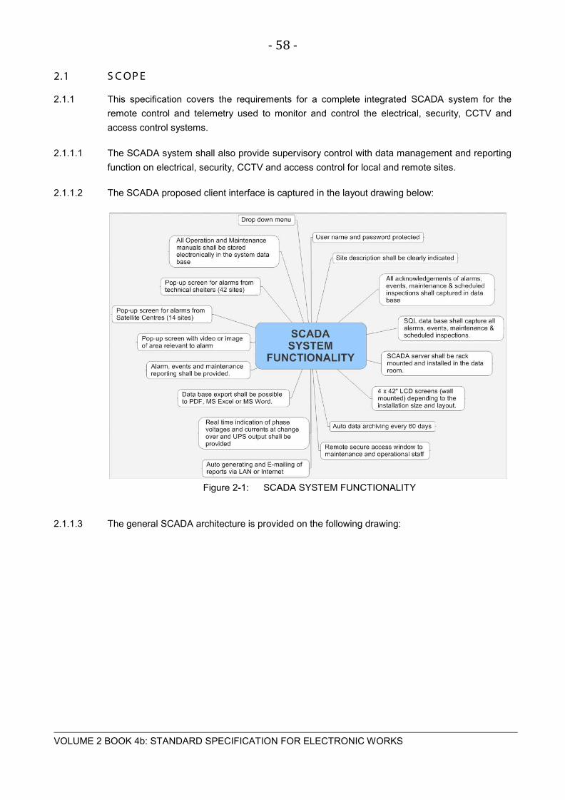
- 58 -
VOLUME 2 BOOK 4b: STANDARD SPECIFICATION FOR ELECTRONIC WORKS
2.1 S C OP E
2.1.1 This specification covers the requirements for a complete integrated SCADA system for the
remote control and telemetry used to monitor and control the electrical, security, CCTV and
access control systems.
2.1.1.1 The SCADA system shall also provide supervisory control with data management and reporting
function on electrical, security, CCTV and access control for local and remote sites.
2.1.1.2 The SCADA proposed client interface is captured in the layout drawing below:
Figure 2-1: SCADA SYSTEM FUNCTIONALITY
2.1.1.3 The general SCADA architecture is provided on the following drawing:

- 59 -
VOLUME 2 BOOK 4b: STANDARD SPECIFICATION FOR ELECTRONIC WORKS
Figure 2-2: GENERAL SCADA ARCHITECTURE

- 60 -
VOLUME 2 BOOK 4b: STANDARD SPECIFICATION FOR ELECTRONIC WORKS
2.1.1.4 The SCADA proposed systems and subsystems and possible alarms are captured in the layout
drawing on the next page.
Figure 2-3: SCADA SYSTEM BASIC PERIPHERAL LAYOUT

- 61 -
VOLUME 2 BOOK 4b: STANDARD SPECIFICATION FOR ELECTRONIC WORKS
2.1.1.5 The SCADA proposed systems and subsystems including alarms, based on the above layout
drawing are summarized below:
2.2 E L E C T R IC AL F E NC E
2.2.1 Electrical fence: Event shall be captured if system is not working and Alarm when triggered.
Event/Alarm (Green/Amber) indication on screen with acknowledgment.
2.3 G S M MODUL E
2.3.1 Controller: Automatic changeover to GSM if Fibre Optic (OF) communication fails or primary
communication fails. Event shall be captured in database. Alarm (Amber) indication on screen
with acknowledgment.
2.4 OV E R T E MP
2.4.1 Wall mounted control unit
2.4.2 Electronic room: Over temperature, set between 19 and 23 degrees.
Temperature indication in real time with Alarm (Red) indication
on screen and alarm captured in database.
2.4.3 Generator room: Over temperature, set between 0 and 55 degrees. Temperature
indication in real time with Alarm (Red) indication on screen and
alarm captured in database.
2.4.4 Events: Store alarm, minimum, maximum and average temperature in
SCADA database with acknowledgement and comments.
2.5 C C T V
2.5.1 Cameras: Security IP cameras for the verification of personnel and
general overview of the facility. Cameras shall be linked to the
alarm system via SCADA when trigged, to open the closest
camera to the event or alarm.
2.5.2 Matrix switch: If required, shall be industrial type switch from SCADA.
2.5.3 Rack, mounted: Shall be installed in existing cabinet in computer room.
2.5.4 Camera housing: Weatherproof up to IP65.
2.5.5 Maintenance monitor: If required, on site for ease of maintenance.
2.5.6 Local DVR: DVR system to store on remote site a minimum of 60 days
video data. Only specific events shall be stored on the SCADA
database if so requested by the Operator.

- 62 -
VOLUME 2 BOOK 4b: STANDARD SPECIFICATION FOR ELECTRONIC WORKS
2.5.7 Store: Images or video on SCADA database of events triggered by the
security or access control system.
2.6 S E C UR IT Y S Y S T E M
2.6.1 Siren: Siren within protected area inside a wire mesh steel protection
enclosure. No exposed wiring.
2.6.2 Controller: All alarm sensors, keypads and remote switching devices shall
report to the control, the controller providing the SCADA system
with all events and alarms. Events and alarms shall be stored
on the controller or local RTU/PLC until uploaded to the SCADA
database.
2.6.3 Tamper: Critical alarm (Red) shall be sent to the controller.
2.6.4 Normal access: Event (Blue) shall be sent to the controller.
2.6.5 Smoke detector: Critical alarm (Red) shall be sent to the controller.
2.6.6 System critical events: Critical alarm (Red) shall be sent to the controller.
2.6.7 System programming events: Event (Blue) shall be sent to the controller.
2.6.8 Database: Event/Alarm (Blue/Amber) send status and database 70% full
alarm.
2.6.9 Data point: USB port to connect to the controller directly to setup, update or
repair the controller.
2.6.10 Door sensors: Device to monitor all the doors via a sensor
2.6.11 Rack mounted: Controller - To be installed in existing cabinet in computer room.
2.6.12 Door access unit: Keypad, TAG reader or Biometrics reader. The reader shall
incorporate all of the different technology if required.
2.6.13 UPS power supply: Controller and all peripherals shall be powered form a backup
battery with a power supply from the main UPS.
2.6.14 Sensor at vehicle gate: Device to monitor all the doors via a sensor.
2.6.15 Indoors motion detection: Microwave & infrared motion detector.
2.6.16 Outdoors motion detection: Microwave & infrared motion detector.
2.6.17 Point detection: Electronic device/sensor or reader detecting or registering a
presence of a person entering or exciting an area.

- 63 -
VOLUME 2 BOOK 4b: STANDARD SPECIFICATION FOR ELECTRONIC WORKS
2.6.18 Beam detection: Electronic device transmitting an infra red beam between a
transmitter and receiver and is triggered when the beam is
interrupted.
2.6.19 Volumetric detection: Electronic device detecting the presence of a moving person in
a specific area.
2.6.20 Relay detection. Store event SCADA database with acknowledgement and
comments. Some events may be stored without
acknowledgement if approved by the Employer
2.7 V OIP C OMMUNIC AT ION R E MOT E S IT E S
2.7.1 VOIP intercom System The VOIP shall form an integral part of the SCADA system and
it shall be possible to access any VOIP intercom through the
system.
2.7.2 UPS power supply The VOIP controller shall have a backup battery that is supplied
with power through the main UPS system.
2.7.3 Phone unit in generator room VOIP phones shall be available in the Generator room.
2.7.4 Phone unit in electronic room VOIP phones shall be available in the electronic/UPS room.
2.8 V OIP C OMMUNIC AT ION S Y S T E M S AT E L L IT E C E NT R E
2.8.1 UPS power supply The VOIP controller shall have a backup battery that is supplied
with power by the main UPS system.
2.8.2 Phone unit in reception VOIP phones shall be available in the reception office.
2.8.3 Phone unit in admin office VOIP phones shall be available in the admin office.
2.8.4 Phone unit in manager office VOIP phones shall be available in the manager office.
2.8.5 Phone unit in generator room VOIP phones shall be available in the generator room.
2.8.6 Phone unit in electronic room VOIP phones shall be available in the electronic room.
2.9 V OIP C OMMUNIC AT ION S Y S T E M T OL L P L AZA
2.9.1 UPS power supply The VOIP controller shall have a backup battery that is supplied
with power by the main UPS system.
2.9.2 Phone unit in reception VOIP phones shall be available in the reception office.
2.9.3 Phone at guard house 01 VOIP phones shall be available in the guard house 01
2.9.4 Phone at guard house 02 VOIP phones shall be available in the guard house 02

- 64 -
VOLUME 2 BOOK 4b: STANDARD SPECIFICATION FOR ELECTRONIC WORKS
2.9.5 Phone unit in admin office VOIP phones shall be available in the admin office
2.9.6 Phone unit in manager office VOIP phones shall be available in the manager office
2.9.7 Phone unit in generator room VOIP phones shall be available in the generator room
2.9.8 Phone unit in UPS room VOIP phones shall be available in the UPS room
2.9.9 Phone unit in electronic room VOIP phones shall be available in the electronic room
2.10 AC C E S S C ONT R OL S Y S T E M
2.10.1 Door lock: Each security door shall have an electronic door lock
mechanism operated via the access control that is linked to the
SCADA system.
2.10.2 Electric Striker lock Specific locking device to be used.
2.10.3 Electromagnetic lock: Specific locking device to be used
2.10.4 Electric Mortice locks: Specific locking device to be used
2.10.5 Controller: All access control devices shall report to the control, the
controller providing the SCADA system with all events and
alarms. Events and alarms shall be stored on the controller or
local RTU/PLC until uploaded to the SCADA database. The
SCADA system shall be able to control each individual device or
peripheral through the controller.
2.10.6 Tamper: All tamper alarms shall be sent to the controller.
2.10.7 Database: The controller shall have a database to store all events until
uploaded to the SCADA system.
2.10.8 Normal access: Access to the facility shall be via a valid process as approved by
the SCADA system and verified by the Contractor.
2.10.9 Door held open: Alarm shall be generated if a door is kept open for 30 seconds.
2.10.10 Door forced open: Alarm shall be generated when a door is opened without any
valid confirmation by the controller and SCADA system.
2.10.11 System critical events: Peripherals not communicating with the controller or any alarm
form the field devices.
2.10.12 System programming events: All programming events shall be stored on the database and
sent to the SCADA system.
- 65 -
VOLUME 2 BOOK 4b: STANDARD SPECIFICATION FOR ELECTRONIC WORKS
2.10.13 Invalid cards/code/fingerprint: Alarm shall be generated on the controller and copied to the
SCADA system.
2.10.14 Data point: A USB port shall connect to the controller directly to setup,
update or repair the controller onsite.
2.10.15 Duress alarm: Alarm event shall be stored by the controller.
2.10.16 Remote: Remotely control the system should the SCADA communication
not be available. Manual operation by technical personnel.
2.10.17 Push button: Used to open a door form the inside. A parallel function shall be
available from the SCADA via the controller.
2.10.18 Gate motor: The motor that operates the vehicle gates. A parallel function
shall be available from the SCADA via the controller.
2.10.19 Door closer: Mechanical device to keep all security doors closed.
2.10.20 Rack mounted: Controller - Shall be installed in existing cabinet in computer
room.
2.10.21 Door controller: Controls the access through the door and sense data to the
controller.
2.10.22 Keypads: Access field device.
2.10.23 Smart cards: Access field device.
2.10.24 Biometric fingerprint reader: Access field device capable to accurate scan identification
against 1000 persons under one second. The device shall be
waterproof, fixed, dust and shock resistant. Provision shall be
made to bypass the biometric fingerprint reader via keypad or
key should the biometric reader fail.
2.10.25 UPS power supply: Controller and all peripherals shall be powered form a backup
battery with a power supply from the main UPS.
2.10.26 Car park control system (Satellite & COC only): System controlling the entering and exiting of
vehicles into and out of the car park.
2.10.27 Emergency door release unit: Break-glass device with key or push button to open a security
door during an emergency.
2.10.28 Store event: Controller and SCADA database with acknowledgement and
comments

- 66 -
VOLUME 2 BOOK 4b: STANDARD SPECIFICATION FOR ELECTRONIC WORKS
2.11 UP S
2.11.1 Inverter off: Report critical alarm (Red) to the SCADA system with
acknowledgment.
2.11.2 Inverter overload: Report critical alarm (Red) to the SCADA system with
acknowledgment.
2.11.3 Mains out of limits: Report critical alarm (Red) to the SCADA system with
acknowledgment.
2.11.4 Battery charger failed: Report critical alarm (Red) to the SCADA system with
acknowledgment.
2.11.5 Store event: SCADA database with acknowledgement and comments
2.11.6 Battery failure: shutdown imminent Report critical alarm (Red) to the SCADA
system with acknowledgment.
2.12 P OWE R QUAL IT Y AND S IT E INF OR MAT ION
2.12.1 Harmonics: Record minimum, maximum and average harmonics to the 3rd,
9th, 12th and 15th to the SCADA system with date and time.
Real-time monitoring shall be available.
2.12.2 Frequency: Record minimum, maximum and average frequency with date
and time. Real-time monitoring shall be available.
2.12.3 Max demand: Record maximum demand with date and time.
2.12.4 Power failure: Record all power failures with date, time and duration with
acknowledgement and comments.
2.12.5 Voltage: Phase, line and system values: Record minimum, maximum and average values with
date and time. Real time monitoring shall be available.
2.12.6 Power: active, reactive, apparent phase and total values: Record minimum, maximum and
average values with date and time. Real time monitoring shall
be available.
2.12.7 Store all event: SCADA database with acknowledgement and comments
2.12.8 PF: power factor per phase: Record minimum, maximum and average values with date and
time. Real time monitoring shall be available.
2.12.9 Energy: import, export, inductive and capacitive values: Record minimum, maximum and
average values with date and time. Real time monitoring shall
be available.

- 67 -
VOLUME 2 BOOK 4b: STANDARD SPECIFICATION FOR ELECTRONIC WORKS
2.12.10 Current: phase and system values: Record minimum, maximum and average values with date
and time. Real time monitoring shall be available.
2.12.11 High/Low: voltage and current readings: Record minimum, maximum and average values with
date and time. Real time monitoring shall be available.
2.13 G E NE R AT OR
2.13.1 Phase loss: Report to SCADA with acknowledgement and comments.
2.13.2 Max demand: Report to SCADA with acknowledgement and comments.
2.13.3 Over voltage: Report to SCADA with acknowledgement and comments.
2.13.4 Under voltage: Report to SCADA with acknowledgement and comments.
2.13.5 Mains failure: Report to SCADA with acknowledgement and comments.
2.13.6 Phase rotation: Report to SCADA with acknowledgement and comments.
2.13.7 Engine over speed: Report to SCADA with acknowledgement and comments.
2.13.8 Auto-start disabled: Report to SCADA with acknowledgement and comments.
2.13.9 Engine start failure: Report to SCADA with acknowledgement and comments.
2.13.10 Engine under speed: Report to SCADA with acknowledgement and comments.
2.13.11 Battery charger failure: Report to SCADA with acknowledgement and comments.
2.13.12 Engine run down cycle: Report to SCADA with acknowledgement and comments.
2.13.13 Load on normal supply: Report to SCADA with acknowledgement and comments.
2.13.14 Generator set in standby mode: Report to SCADA with acknowledgement and comments.
2.13.15 High engine temperature: Report to SCADA with acknowledgement and comments.
2.13.16 Water jacket heater failure: Report to SCADA with acknowledgement and comments.
2.13.17 Load on emergency supply: Report to SCADA with acknowledgement and comments.
2.13.18 Store event on SCADA database with acknowledgement and comments: Report to SCADA with
acknowledgement and comments.
2.13.19 Low level alarm on day tank 180L: Report to SCADA with acknowledgement and comments.
2.13.20 Low level alarm on bulk tank 600L to 48 000L (site dependent): Report to SCADA with
acknowledgement and comments.

- 68 -
VOLUME 2 BOOK 4b: STANDARD SPECIFICATION FOR ELECTRONIC WORKS
2.13.21 HT alarms and indication where applicable: Report to SCADA with acknowledgement and
comments.
2.14 G E NE R AL
2.14.1 The SCADA system shall provide the Contractor with real time reporting and alarm notification
on systems installed to assist with the successful management and operation of the
infrastructure i.e. electrical, security, access control, CCTV, VOIP phone system and other
equipment.
2.14.2 All equipment as listed under item 18.2 to 18.3 shall be supplied and installed with an RS 232,
RS 485 or Ethernet LAN (TCP/IP) communication protocol. A network switch may be required
depending on the site and equipment. This communication protocol shall be used to
communicate through a local PLC or RTU intelligent interface unit.
2.14.3 All signals shall be processed at each location (Remote site) before they are sent via the
communication backbone to the SCADA system in the control room.
2.14.4 Each site shall have a cabinet to house the rack mounted PLC or RTU and communication
equipment that is required to interface the different peripherals with the SCADA system.
Equipment that will be housed outside the cabinet shall be housed in an extruded aluminium
enclosure and shall be suitable for wall mounting. The complete unit shall have a protection
rating of IP 55.
2.14.5 Each site may have a dedicated remote site client for onsite maintenance and system repair
work. All site related data shall be stored on site for a period of 60 days before it is replaced.
Data shall only be replaced or deleted if the data have been sent to the main database at the
Central Operational Centre.
2.14.6 Any access to the system or database shall be password protected.
2.14.7 Each site shall have a preconfigured hard drive for quick system repair.
2.14.8 Each site shall have a dedicated recover pack for quick recovery of the system should any
failure occur over and above the preconfigured hard drive under item 18.14.7.
2.14.9 All sites shall be protected against unauthorized personnel to use or access the SCADA
hardware and software.
2.14.10 The SCADA system shall be able to override, switch or configure any of the hardware devices
on the network for maintenance, operation and testing purposes.
2.14.11 The SCADA system shall test the communication with each peripheral once every 600 seconds.
Failure of any device shall be reported by the SCADA system.
2.14.12 Any alarm reported by the SCADA system shall be acknowledged by and register SCADA user.
The acknowledgement shall be with a user name and password or biometric reader.

- 69 -
VOLUME 2 BOOK 4b: STANDARD SPECIFICATION FOR ELECTRONIC WORKS
2.14.13 The SQL database shall record the alarm or event, date, time, registered user details,
comments by user (user must provide comments to complete the acknowledgement), time
duration from alarm notification to acknowledgement.
2.14.14 The SCADA system shall allocate a unique serial number to each alarm or event for audit
purposes. In addition to each unique number a unique number shall also be provided per
discipline i.e. A001 (Access control); S001 (Security); G001 Generator, etc. The serial number
shall no have a limit. Other unique serial numbers may be required for maintenance and repair
actions.
2.14.15 The database shall count each alarm or event and shall provide a report every month on the
total alarms or events for the month and also overall count.
2.14.16 The SCADA database shall provide graphs of all the alarms and events per site and shall
highlight any abnormalities or above-average occurrences.
2.14.17 The control room shall have a minimum of four 42” (108mm) LCD screens (preferably wall
mounted) to view the overall layout of the architecture, the database with details of the latest
alarms and events, and CCTV and alarm access control. This may change depending on the
control room layout and client requirements.
2.14.18 The SCADA system shall be able to communicate via a GSM communication device should the
communication backbone not be available. The GSM communication device shall send Short
Text Message System (SMS) messages to several cell phones. The SCADA system shall also
store all messages sent, with a date and time stamp in a user-friendly database.
2.14.19 The SCADA system shall be able to communicate via a GSM/GPRS communication device
should the communication backbone not be available. The GSM/GPRS communication device
shall send emails to several addresses. The SCADA system shall also store all messages sent,
with a date and time stamp in a user-friendly database.
2.14.20 The SCADA system shall be able to communicate via a SMS or email, several dedicated
personnel alarm conditions as may be required by the Contractor for each site or from the
control centre.
2.14.21 The SCADA system shall be maintained by suitably skilled personnel that will ensure that the
system gets the required maintenance.
2.14.22 Remote access may be required should the SCADA system be maintained by a subcontractor.
2.14.23 The SCADA architecture shall be based on available drawings for each site with an overlay of
all the peripherals that will be easily identified and controlled. Drawings shall be made available
in PDF, CAD or DXF file format. Other formats may be available if agreed to by the Employer.
2.14.24 Required antivirus and firewall protection and security shall be provided.

- 70 -
VOLUME 2 BOOK 4b: STANDARD SPECIFICATION FOR ELECTRONIC WORKS
2.15 E QUIP ME NT R E C OR D S Y S T E M (E R S )
2.15.1 The SCADA shall have an integrated ERS that will be updated and electronically stored in the
SQL database. Each peripheral shall have a unique number as labelled in the field. The ERS
will be updated every time maintenance is done or when equipment is replaced. The SCADA
system shall be able to generate a trend report to indicate the movement or status of
peripherals. The unique number shall identify the site, location and equipment.
2.15.2 The SCADA system shall allocate unique numbers automatically to the asset, based on the
following:
2.15.3 Drop down menu – SITE (e.g. Toll Plaza name).
2.15.4 Drop down menu – LOCATION (e.g. Generator or control room)
2.15.5 Drop down menu – EQUIPMENT (UPS, Battery, Camera, PLC, etc)
2.15.6 Drop down menu – AUTO NUMBER (The number to be complied based on the above selection
and as specified in the project specification)
2.15.7 Edit number – only authorized personnel shall have access to this option.
2.15.8 Other detail to follow after the number has been allocated i.e.
2.15.9 Equipment serial number to be loaded
2.15.10 Model number
2.15.11 Make
2.15.12 Supplier details including contact numbers
2.15.13 Future replacement date
2.15.14 Installation date.
2.16 C OMP UT E R IS E D MAINT E NANC E MANAG E ME NT S Y S T E M (C MMS )
2.16.1 A complete CMMS shall be provided for the electrical and mechanical equipment including any
other type of asset. The system shall make use of the ERS data on the system and keep track
of maintenance and status of equipment and software.
2.16.2 The CMMS shall keep track of but is not limited to the items below:
2.16.3 Maintenance;
2.16.4 Breakdowns;
2.16.5 Response and repair times;
- 71 -
VOLUME 2 BOOK 4b: STANDARD SPECIFICATION FOR ELECTRONIC WORKS
2.16.6 Inventory control;
2.16.7 Guarantee periods;
2.16.8 Reports;
2.16.9 Personnel;
2.16.10 Hours operational;
2.16.11 Hours down;
2.16.12 Work orders;
2.16.13 Additional functionality shall be allowed for without the need to update the software.
2.17 WOR K S T AT ION
2.17.1 One or more workstations shall be provided in the control room or any other control area with
the Human Machine Interface (HMI) software. The workstation shall have sufficient storage
capacity or be linked to any other large storage facility i.e. NAS as required.
2.18 S E R V E R
2.18.1 One or more servers shall be provided in a master slave configuration to allow for redundancy.
The redundant servers shall synchronize both real-time and historical data on failure restoration.
2.18.2 The redundant servers shall offer full shadowing or parallel scanning to external drives. This will
be a configurable attribute. Either of the servers shall be able to act as master.
2.18.3 The switchover to the standby system shall be bumpless and continuous control shall be
possible.
2.19 S OF T W AR E R E QUIR E ME NT S
2.19.1 The Supervisory control and data Acquisition software package shall be standardised and have
a wide and well established user base in the South African and international markets. The
software shall be a native 32-bit or 64-bit application and must run on the latest available
Operating System recommended by the SCADA supplier including the .NET framework.
Preference shall be given to a locally developed and supported SCADA package. A software
support service with optional updates shall be available. Software shall be fully supplemented
by easily understandable user manuals and documentation.
2.19.2 Any other operating system may be provided if approved by the Employer.
2.19.3 The Contractor shall indicate the location and level of software support available.

- 72 -
VOLUME 2 BOOK 4b: STANDARD SPECIFICATION FOR ELECTRONIC WORKS
2.19.4 The editing of mimic displays and database tag configuration shall be possible on-line without
compromising the availability of the installation. No compilation of the database shall be
required.
2.19.5 The system shall be upgradeable to all new versions as they become available. Should this be
an annual agreement please include all relevant documentation.
2.20 S QL DAT AB AS E
2.20.1 All data shall be stored on an SQL database with easy and unrestricted access to the data for
compiling reports or to import into other database facilities.
2.21 S OF T W AR E L IC E NC E
2.21.1 The Operator shall purchase perpetual, unrestricted licences, where any is required, for all
software i.e.: operating systems, databases, application software, firmware, etc. for any new
equipment and/or systems in the name of the Employer so that any proprietary rights in respect
of such software and/or hardware
2.21.2 Licences vest in the name of the Employer. There shall be no time or period-related restrictions
on any such licences or system functionality
2.21.3 The following minimum licences shall be provided but not limited to:
2.21.3.1 Operating System (OS) – Individual licences.
2.21.3.2 OS client access licence (Microsoft CALs) – Minimum of 10 (Site dependent)
2.21.3.3 OS remote connection licences – Minimum of 4 (Site dependent)
2.21.3.4 Application licence – MS Office, MS SQL server, third party licences, and other.
2.21.3.5 SCADA – Licences.
2.21.3.6 Proof of validity of all compiling and third party licences shall be required.
2.22 DAT A C OMMUNIC AT ION
2.22.1 Data communication shall be Ethernet through a Wide Area Network (WAN) and Local Area
Network (LAN) by means of TCP/IP. All communication hardware shall be industrial type to the
Employer’s approval.
2.23 NE T WOR K ING
2.23.1 The package shall be capable of transparently supporting distributed multi-client, multi-server
configurations. In this configuration, the database shall be distributed among the server stations
with each one scanning its front-end device(s) and updating its own database. Server stations
must have the ability of being able to communicate simultaneously, to equipment from various
hardware suppliers, on a single station

- 73 -
VOLUME 2 BOOK 4b: STANDARD SPECIFICATION FOR ELECTRONIC WORKS
2.23.2 All database items shall be transparently available on all operator stations via a dedicated
network. This includes mimic displays, trending, reporting and alarms. There shall be no
appreciable degradation in response time between subscriptions to local database items, and
subscriptions to database items in another server station.
2.23.3 The SCADA system must allow client stations to connect to server stations via a remote link.
2.24 NE T WOR K S E C UR ITY
2.24.1 The highest possible network security shall be implemented for data transmission, data storage
and human interface security. The security shall be comprehensive, complete and integrated
with the operating system’s security system.
2.24.2 The software shall provide a comprehensive security system. The security system must
integrate smoothly with the operating system’s security system. It must be possible to
completely disable all Operating System controls like Title Bar, Sizing Border, Menu, status bar,
etc., and thereby create a totally tamper-proof operator interface. Remote user interfaces shall
have the ability to be downgraded to view only capability, whereas their default capability should
be viewed and controlled. The package will allow the use of dynamic security descriptors, i.e.
the security of any operator action may be dynamically changed based on certain conditions.
2.24.3 Security should be Operating System profile dependent and shall conform to the windows
security policies. Should any other OS be implemented other than Windows, the same security
requirements shall apply. Logging into the system from any terminal shall apply the necessary
security from the domain controller.
2.25 .NE T F R AME WOR K
2.25.1 The software should be able to consume WEB services and to embed .NET controls. This
functionality should be native to the application and make full use of the .NET framework. The
application should be developed on the .NET framework and no additional software should be
required to allow the full framework functionality.
2.26 NOT IF IC AT ION
2.26.1 The SCADA system shall have an SMS and email facility that can be set up to send alarms,
reports, equipment statuses, etc. manually or automatically as required. A minimum of 10 SMS
and e-mail accounts shall be possible.
2.27 R E MOT E AC C E S S
2.27.1 Remote access shall be available through the WAN, LAN or GSM/GPRS network. Other
communication may also be implemented if approved by the Employer.
2.27.2 The clients should be able to run on a LAN/WAN or as a WEB client on the Internet or Internet
without deploying multiple front ends.
2.28 OT HE R C ONNE C T IV IT Y

- 74 -
VOLUME 2 BOOK 4b: STANDARD SPECIFICATION FOR ELECTRONIC WORKS
2.28.1 The SCADA shall allow for additional data types to be connected. This should include
databases as well as WEB services, OPC and others. Connectivity should allow data types to
be used within the SCADA client. This might include being able to query data from data tables
for use in the SCADA. Data connectors shall be able to be added without affecting the
installation.
2.29 INT E G R AT ION AND INT E R OP E R AB IL IT Y
2.29.1 The system shall support all the current de facto industry standards for open system interfaces –
such as OLE, DDE and, CSV. The Software shall easily and seamlessly connect to other third
party applications such as Excel, Lotus, Access, SQL Server, Oracle, Delphi, PowerBuilder,
Visual Basic, etc. SCADA systems that ‘lock’ the user into one programming
language/environment cannot be used. All properties or attributes of all tags must be accessible
this way, i.e. no artificial restriction to value only attributes will be acceptable. An ODBC, ADO
and OLEDB native interface should be supported without the requirement for additional software
or extra coding. The interfaces shall allow the SCADA to log any attribute of any tag into a log
file or into a database at the same time with different sample resolutions.
2.29.2 The SCADA shall be able to interact with a database bi-directionally and a specific field in a
specific table should be able to be browsed form within the SCADA.
2.30 E XP ANDAB IL IT Y
2.30.1 The software and hardware shall be able to be expanded to allow for any future additions or
modification to the installation.
2.31 HUMAN MAC HINE INT E R F AC E (HMI)
2.31.1 The HMI shall allow the user to interact with the SCADA system in an easy to understand and
user friendly way. The HMI shall have the following functions on the main screen (depending on
the size of the installation, more than one screen may be used):
2.31.2 Overview of the electrical equipment under supervision.
2.31.3 Background drawing of the facility with interactive symbols overlay.
2.31.4 Photo or graphical image of the electrical or any other device being supervised by the system.
2.31.5 Main drop down menu with authorization to other information as listed on the drop down menu
or as specified in the project specification.
2.31.6 Drop down menu with predefined selections to best describe the problem.
2.31.7 Login or logout selection or biometrics login or logout.
2.31.8 Auto logout by the system.
2.31.9 Acknowledgement of alarm area or pop-up screen.

- 75 -
VOLUME 2 BOOK 4b: STANDARD SPECIFICATION FOR ELECTRONIC WORKS
2.31.10 All electrical information to be stored and easily available.
2.31.11 Facility to upload data onto the database.
2.31.12 Screen to change to display relevant data of the event or alarm.
2.31.13 Display status on all communication protocols available.
2.31.14 The security to be set for each type of user by an administrator or master user.
2.31.15 The security levels shall be set up in accordance to the security levels as required by the
Employer. The system shall be fully flexible in this regard.
2.31.16 No Internet or any Operating System application shall be available when the SCADA system
GUI is running. Only an approved user shall have the authority to shut down the application and
only by logout.
2.31.17 All events shall be logged in the database.
2.31.18 Any peripheral that can be switched, started, stopped, opened, closed or powered up or down or
whatever the case may be, shall be fully interfaced with the HMI.
2.31.19 The Contractor shall note that the items listed in the standard specification are the minimum
requirements of the system and additional functionality may be required.

- 76 -
VOLUME 2 BOOK 4b: STANDARD SPECIFICATION FOR ELECTRONIC WORKS
Figure 2-4: HMI (DROP DOWN MENU)

- 77 -
VOLUME 2 BOOK 4b: STANDARD SPECIFICATION FOR ELECTRONIC WORKS
Figure 2-5: SCADA SYSTEM EVENT NOTIFICATION FLOW CHART
Event
Occurs
Pop-up screen with
notification message
Identifiable
Audio Sound
Non-Critical
Event or
Notification
Operator’s
Acknowledgement
Event Stored In
SQL Data Base
Critical
Event
Description /
Action Comment
Authorization
SCADA
system
Pop-up
Close
Site Specific
Visual Display
return to
normal
Identifiable
Audio Sound
Operator’s
Acknowledgement
Event Stored In
SQL Data Base
SCADA
System
Reports
Operators Action
Reports to all parties
Event Date Event Time Act Date Act timeDescription /
Action Comment
Event
Description
Fixed Date Fixed timeDuration Final Problem
description
SCADA SYSTEM EVENT NOTIFICATION FLOW CHART
Access control
verification
and control
Over All
Visual Display
Visual Data
Base Display
and Access
Including
Reports
Visual Display
return to
normal
HMI 01
HMI 02 HMI 03 HMI 04
Input from Maintenance
Personnel or Specialist
Subcontractor
Event Serial
No.

- 78 -
VOLUME 2 BOOK 4b: STANDARD SPECIFICATION FOR ELECTRONIC WORKS
2.32 R E P OR T ING
2.32.1 Detail, complete and user-friendly reports shall be easy available to the user for the operation
and maintenance of the installation. The reports shall include but not be limited to the following:
2.32.2 Comprehensive report.
2.32.3 Equipment/Peripheral status report.
2.32.4 Equipment failure report.
2.32.5 Alarm notification report.
2.32.6 Event notification report.
2.32.7 Combined alarm and event notification report.
2.32.8 Maintenance report.
2.32.9 Operational report.
2.32.10 Generator report.
2.32.11 UPS report.
2.32.12 Temperature report.
2.32.13 Power Quality report.
2.32.14 Access control system report.
2.32.15 Alarm system report.
2.32.16 CCTV system report.
2.32.17 Trend report.
2.32.18 Outstanding items list report.
2.32.19 The reports shall be divided in sub-reports with dedicated serial numbers that can be audited
and verified that they are complete and correct.
2.32.20 All logged data are automatically summarized each night for historical reports. Users have the
option to print out the standard reports included with the SCADA System or create their own
reports by requesting the SI to implement a new report type. All logged data can also be
imported into Microsoft Excel.
2.32.21 There are four report types in the Report Module that an operator can select and each report
type displays data from a different viewpoint over a specified period selected by the user.

- 79 -
VOLUME 2 BOOK 4b: STANDARD SPECIFICATION FOR ELECTRONIC WORKS
Daily - prints and displays a report of hourly averages and totals for the date selected. The user may select Month, Day, Year and Starting and Ending Hour in military time for the report.
Weekly - prints and displays a report of daily averages and totals for seven days from a beginning date. The user may select Month, Day, and Year. The date is the first day of the reported week.
Monthly - prints or displays a report of the daily averages and totals for a selected month and day range. The user may select Month, Year and Starting and Ending days for the report.
Yearly - prints or displays a report of the monthly averages and totals for a selected year and month range. User may select Year and Starting and Ending months for the report.
2.32.22 Each Report Style (Period and Instance) is used differently according to the selected Report
Type (Daily, Weekly, Monthly and Yearly).
2.32.23 Period Reports are intended to show totals and averages for a time frame. Instance Reports are
intended to show the actual values at an instant in time.
2.32.24 Reports are:
Detail Reports - using up to 10 variables per report, these reports break down one site in hourly format for daily reports, daily format for weekly and monthly reports, and monthly format for yearly reports. Also, Detail Reports can be set up for one variable over several sites. These reports are usually used to troubleshoot a site or sites at 24-hour intervals.
Summary Reports - give the totals or averages for all sites at once. These reports are the best for typical system reports and helpful in locating a site that needs watching more closely.
Combination Reports - allow several daily reports to be printed at once. The best use for this report style is for monitoring several sites over several days. It saves the user time printing several daily reports at one time instead of each report being selected and printed one by one.
Graphs - allow trends to be seen quickly and can be viewed in several formats. The trends can be set up to display the system's averages or one site's averages. The graphs can be viewed in 2-D or 3-D with bars, lines, curves, etc. The graph data can be copied to the clipboard, titles can be changed, and the scale can be changed.
2.32.25 Instance Reports are:
History Reports - show every variable logged by the system with a timestamp and can be set up for all sites at once in a
- 80 -
VOLUME 2 BOOK 4b: STANDARD SPECIFICATION FOR ELECTRONIC WORKS
group or one site at a time. The number of data types is selectable from all to one. Though this is a great debugging tool, it is recommended to print one site at a time because this report can become very long.
Last Instance Reports - show the last polled value for all sites at once or in a group or for the specific selected item i.e. fuel level of a specific generator. This report is the best way to see the system's current state.
2.32.26 The SCADA shall have the function to export any report to PDF or excel format.
2.33 OB J E C T OR IE NT E D G R AP HIC S
2.33.1 Mimic screens shall be graphically based on dynamic and static objects (where possible, real
images of the equipment shall be used). The system shall support true vector based graphics
and allow unlimited panning and zooming without any degradation in mimic resolution and
sharpness. There shall be no limitation to the screen resolution and/or number of colours
supported. A comprehensive standard graphics symbol library shall be provided that will allow
modification and/or adding of custom symbols to the library easily without requiring additional
software. All library symbols shall support unlimited panning, zooming and sizing. It shall be
possible to dynamically move, size and rotate all graphic objects linked to changes of state in
the online database.
2.33.2 The package shall have conventional CAD type editing facilities to ensure that the mimics are
easy to build and modify. It shall be possible to launch third party applications from within a
graphic page, by operator action or on process event, as well as configure user-specified,
process-triggered, hypertext help pages for display.
2.33.3 The SCADA system shall allow mimics to be “replayed” from historically logged data as well as
live real-time data. The Operator must have the ability to simply toggle a real-time mimic into
historical mode. The replay feature shall be in-built and should not require additional
configuration. The SCADA shall support dynamic toll tips allowing multiple tags to be configured
and updated in the toll tip.
2.33.4 User Interface adaptability will allow for the creation of new presentation layer objects such as
pictures trends, wizards, templates, animation behaviours, alarm and event views, etc.
Templates shall be supported for trends and graphic pages. The tag assignment shall depend
on the selection of the common plant areas.

- 81 -
VOLUME 2 BOOK 4b: STANDARD SPECIFICATION FOR ELECTRONIC WORKS
2.34 F AUL T T OL E R ANT
2.34.1 The package shall be capable of supporting a distributed active fault tolerant cluster model.
This must provide the following:
2.34.2 A true fault tolerant system – providing the basis for continuous availability of the system.
2.34.3 System integrity – the system’s permanent and cached data shall be duplicated so that any
component failure will not result in the loss of data for the remaining components.
2.34.4 Clustering of the fault tolerant server nodes – the duplicate server nodes should appear as one
logical unit from any client’s perspective.
2.34.5 Continuous availability – the system shall detect a node failure and quickly take appropriate
action so that the remaining components can continue uninterrupted thereby providing clients
with continuous live data and operation.
2.34.6 Active fault tolerant clustered nodes – duplicate nodes are actively involved in useful work
thereby providing increased throughput of the system.
2.35 INT E R F AC E
2.35.1 The system shall support all the current de facto industry standards for open system interfaces –
OLE, DDE, CSV. The Software shall easily and seamlessly connect to other third party
applications such as Excel, Lotus, Access, SQL Server, Oracle, Delphi, PowerBuilder, Visual
Basic, etc. SCADA systems that ‘lock’ the user into one programming language/environment will
not be considered for this project. All properties or attributes of all tags must be accessible this
way, i.e. no artificial restriction to value only attributes will be acceptable. An ODBC, ADO and
OLEDB native interface should be supported without the requirement for additional software or
extra coding. The interfaces shall allow the SCADA to log any attribute of any tag into a log file
or into a database at the same time with different sample resolutions.
2.35.2 The SCADA shall be able to interact with a database bi-directionally and a specific field in a
specific table should be able to be browsed form within the SCADA.
2.36 R E MOT E OP E R AT ION
2.36.1 The SCADA system shall have the functionality to switch or start equipment or peripherals as
may be needed for access or to test equipment i.e. open locks for maintenance personnel or
start a generator to test the unit, etc.
2.36.2 All remote tests shall be stored in the database with the required authorization and a short
description on the test details. The maximum average and minimum values of the test shall be
automatically stored in separate fields that are specific to the test. Any out of specification
values shall be reported by the SCADA system. All fields populated automatically shall not be
editable.

- 82 -
VOLUME 2 BOOK 4b: STANDARD SPECIFICATION FOR ELECTRONIC WORKS
2.37 R E C OV E R Y P AC K
2.37.1 The SCADA system shall have a full recovery pack with all data and software to reinstall on a
server when required. Cloning of the server can also be considered for fast and quick recovery
or setup in when required.
2.38 AUDIT AND V E R IF IC AT ION
2.38.1 The software shall provide a complete audit and verification facility.
2.39 S UP P OR T
2.39.1 Sufficient support shall be available for the hardware and software.
2.40 G UAR ANT E E
2.40.1 A minimum of 12 months guarantee shall be provided for the hardware and software on
workmanship and system failure.
2.41 INDUS T R IAL S T ANDAR DS
2.41.1 The following industrial standards shall apply.
2.42 L AB E L L ING
2.42.1 All hardware and cabling shall be labelled and be easily traceable in the schematic drawings to
be provided. The Contractor shall get approval from the Employer for the proposed labelling to
be used. It may be necessary to do one site for approval should it be required by the Employer,
prior to manufacture.
2.42.2 All labelling and schematics shall be stored electronically on the SCADA system.
2.43 OP E R AT ION
2.43.1 The SCADA system shall be a user-friendly Windows based or similar approved operating
system that can easily be modified to comply with changing environments and operational
requirements.
2.43.2 One or more personnel shall monitor and operate the SCADA system to ensure all alarms and
events are attended to in the shortest possible time. The Contractor shall provide additional
personnel should it be required by the system.
2.44 C OMMIS S IONING
2.44.1 Commissioning is a quality-orientated process for achieving and documenting that the
performance of systems, facilities and assemblies meets pre-defined objectives and criteria.
2.44.2 COMMISSIONING REQUIREMENTS

- 83 -
VOLUME 2 BOOK 4b: STANDARD SPECIFICATION FOR ELECTRONIC WORKS
The Contractor shall provide a detailed Commissioning matrix and commissioning procedure
that details the acceptance testing and commissioning of the SCADA system. Example base
matrix (incomplete) is indicated in clause 3.50. Note that columns under Commissioning are
called Operational functionality, Quality, Risks and Efficiency. The test procedure must be
defined in each of these columns to verify the compliance of each of the items in terms of the
specification.
SCADA GUI (Operational Functionality): Use this field to describe the scenarios that need to be
tested from an “Operator” point of view (What functionalities this item requires).
DB Management: Use this field to clarify what records need to be inserted into the database for
the different states or scenarios.
Risks: Use this field to list possible risks. These risks can be physical or system related.
Test Procedure: Use this field to describe a test procedure that will ensure that all functionalities
and scenarios are covered.
2.45 DE F INE T HR E AT S , R IS K S AND C ONS E QUE NC E S
2.45.1 It is important to note that a part of the purpose of Commissioning is to ensure that functions
and procedures etc. are working safely and properly. Before testing commences, it is important
to understand that certain procedures may fail, causing damage to equipment or endangering
lives. These types of risks need to be identified beforehand and listed in the Risks column.
Before each test commences, anticipated risks must be isolated or eliminated as best possible
and where not possible, disaster recovery procedures must be in place in the event of
malfunction to minimise the effect.
2.46 S P E C IAL T E S T ING NE E DS
2.46.1 It is important to note that in order to facilitate a Commissioning test, there may be specific
needs for different equipment. There will almost always be a requirement for teams of people
on the operator’s side and on the plant side with proper communication equipment to
successfully conduct these tests. Other specialized Contractors and pre-arranged conditions
may also be required for testing.
2.47 DOC UME NT C OMP L IANC E
2.47.1 During and after Commissioning, the documentation used for testing serves as a historical
record of the Employer’s expectations and performance delivered.
2.47.2 Testing and Maintenance documentation must be provided and verified with the process of
Commissioning.

- 84 -
VOLUME 2 BOOK 4b: STANDARD SPECIFICATION FOR ELECTRONIC WORKS
2.47.3 Operating and Training Manuals must also be provided and verified during the process of
Commissioning.
2.48 INS P E C T IONS & T E S T ING
2.48.1 The manufacturer shall carry out the following factory acceptance testing in order that the
Employer may witness compliance of the SCADA client layout and operation, reporting and
functionality to the specified requirements:
Layout to be approved including functionality. A functional layout may be proposed for the
Employer to approve.
Database to be approved including functionality. A functional layout may be proposed for the
Employer to approve.
Reports to be approved. Report layout to be approved by the Employer.
Each alarm condition to be simulated, acknowledged, captured in database and reported in any
on the required reports as selected.
Each visual alarm to be tested.
Each audible alarm to be tested.
Alarm sequencing verification.
Each peripheral to be tested for responsiveness. Peripheral to open/close, stop/ tart, etc. when
selected.
Test email and SMS functionality.
Test recovery pack. The recovery test will be one on a separate server with only an OS loaded.
The server that replaces the existing and the SCADA system shall function without any changes
or setup changes. Only contact details may be changed. The software must be able to generate
a recovery disk when requested or once every year.
Check drawings and single line diagrams proposed including descriptions and labelling. Original
layout drawings of the infrastructure shall be used where possible.
2.48.2 The manufacturer shall carry out the following site acceptance testing in order that the Employer
may witness compliance of the SCADA system to the specified requirements:
Test all alarm functionality as per the factory acceptance testing.
Test database functionality as approved during the factory acceptance testing.
Audit reports based on site testing.
Each visual alarm to be tested.

- 85 -
VOLUME 2 BOOK 4b: STANDARD SPECIFICATION FOR ELECTRONIC WORKS
Each audible alarm to be tested.
Test fibre optic and GSM communication.
Test email and SMS functionality.
Check drawings and single line diagrams proposed including descriptions and labelling.
2.49 DR AWING S AND INF OR MAT ION
2.49.1 The Contractor shall submit full details of the SCADA system, including the following:
Complete hardware and software list.
List of software licences.
A drawing indicating all dimensions of the alarm panel and equipment layout.
A drawing indicating typical mounting and fixing details. These drawings shall clearly indicate all
dimensions of the component items, electrical fixing details and electrical connections.
2.49.2 The Contractor shall provide 3 sets of operating manuals for the alarm system as installed, prior
to final Commissioning for approval.
2.49.3 The manuals shall contain comprehensive technical data catalogues; operating instructions and
detailed wiring diagrams complete with cable wire and core numbering as well as terminal block
numbering.
2.49.4 The Contractor shall provide full details of spares sourcing at the time of handover.

- 86 -
VOLUME 2 BOOK 4b: STANDARD SPECIFICATION FOR ELECTRONIC WORKS
2.50 S C ADA DAT A AND C OMP L IANC E S HE E T
Table 2-1: SCADA DATA AND COMPLIANCE SHEET
ITEM STANDARD DESCRIPTION COMPLY COMMENTS/
SIGNATURE YES (√) NO (X) N/A (X)
N/A
SCADA
CLAUSE
3.50.1 3.2 ELECTRICAL FENCE
3.50.2 3.3 GSM MODULE
3.50.3 3.4 OVER TEMP
3.50.4 3.5 CCTV
3.50.5 3.6 SECURITY SYSTEM
3.50.6 3.7 VOIP COMMUNICATION/ PABX
3.50.7 3.8 VOIP PHONE/INTERCOM SYSTEM SATELLITE CENTRE
3.50.8 3.9 VOIP PHONE/INTERCOM SYSTEM COC
3.50.9 3.10 ACCESS CONTROL SYSTEM
3.50.10 3.11 UPS
3.50.11 3.12 POWER QUALITY AND SITE INFORMATION
3.50.12 3.13 GENERATOR
3.50.13 3.14 General
3.50.14 3.17 Workstation
3.50.15 3.18 Server
3.50.16 3.19 Software requirements
3.50.17 3.20 SQL database
3.50.18 3.21 Software licence
3.50.19 3.22 Data communication
3.50.20 3.23 Networking
3.50.21 3.24 Network security
3.50.22 3.25 .Net framework
3.50.23 3.26 Notification
3.50.24 3.27 Remote access
3.50.25 3.28 Other CONNECTIVITY
3.50.26 3.29 Integration and

- 87 -
VOLUME 2 BOOK 4b: STANDARD SPECIFICATION FOR ELECTRONIC WORKS
ITEM STANDARD DESCRIPTION COMPLY COMMENTS/
SIGNATURE YES (√) NO (X) N/A (X) interoperability
3.50.27 3.30 Expandability
3.50.28 3.32 Reporting
3.50.29 3.33 Object oriented graphics
3.50.30 3.34 Fault tolerant
3.50.31 3.35 INTERFACE
3.50.32 3.36 REMOTE Operation
3.50.33 3.37 RECOVERY PACK
3.50.34 3.38 Audit and verification
3.50.35 3.39 Support
3.50.36 3.40 Guarantee
3.50.37 3.41 Industrial standards
3.50.38 3.42 Labelling
3.50.39 3.43 Operation
3.50.40 3.44 Commissioning
3.50.41 3.45 COMMISSIONING GOALS
3.50.42 3.46 DEFINE THREATS, RISKS AND CONSEQUENCES
3.50.43 3.47 SPECIAL TESTING NEEDS
3.50.44 3.48 DOCUMENT COMPLIANCE
3.50.45 3.49 Inspections & Testing
3.50.46 3.50 DRAWINGS AND INFORMATION

- 88 -
VOLUME 2 BOOK 4b: STANDARD SPECIFICATION FOR ELECTRONIC WORKS
S E C T ION 3 S E C UR IT Y AND AC C E S S C ONT R OL R E QUIR E ME NT S

- 89 -
VOLUME 2 BOOK 4b: STANDARD SPECIFICATION FOR ELECTRONIC WORKS
3.1 INT R ODUC T ION
3.1.1 Security Elements
3.1.1.1 The minimum functions required for the security and access control system are:
a) Deterrence (e.g. fencing, access control with guardhouse, visible CCTV cameras)
b) Detection (e.g. alarm sensors, CCTV)
c) Assessment (e.g. CCTV verification of alarm sensors)
d) Reaction (e.g. audio communication with intruder)
e) Evidence gathering (e.g. logging of alarms and recording of CCTV images)
3.1.1.2 The Command Centre will be housed in the Central Operations Centre from where operators
will monitor all the security activities.
3.1.2 Typical security levels
3.1.2.1 The security will be divided into five (5) levels with the following specifications:
a) Level 0: This level will enforce access control with security fencing and security
gates with manual locks.
b) Level 1: This level will enforce access control with security doors and gates with
magnetic and/or electric locks.
c) Level 2: This level will enforce access control with security doors and gates with
magnetic and/or electric locks in conjunction with smart card readers and
cards.
d) Level 3: This level will enforce access control with security doors and gates with
magnetic and/or electric locks in conjunction with biometric readers with
incorporated keypads.
e) Level 4: This level will enforce access control with security doors and gates with
magnetic and/or electric locks in conjunction with biometric readers with
incorporated keypads and CCTV.
f) Level 5: This level will enforce access control with security doors and gates with
magnetic and/or electric locks in conjunction with smart card readers and
cards, biometric readers with incorporated keypads and CCTV in
conjunction with CAT 4 safe doors.

- 90 -
VOLUME 2 BOOK 4b: STANDARD SPECIFICATION FOR ELECTRONIC WORKS
3.1.2.2 In general, the facility design should be such that movement to and from a certain level of
security should be through the next higher or lower security level.
3.1.3 Toll Plaza levels
3.1.3.1 The Central Operations Centre will be divided into the following areas with associated security
levels:
a) Level 0: The area within the fenced area (the total external site)
b) Level 1: The public access area inside the Toll Plaza area/ building
c) Level 2: Restricted staff area
d) Level 3: Control Centre and Management area
e) Level 4: Server room
f) Level 5: Vault and Cash Up Room
3.1.4 Satellite or remote sites Security Levels
3.1.4.1 The Satellite or Remote sites will be divided into the following areas with associated security
levels:
a) Level 0: The area within the fenced area (the total external site)
b) Level 1: The public access area inside the Satellite Centre building
c) Level 2: The area beyond the first set of doors and stairs
d) Level 3: Management area and area where desks are to serve the public
e) Level 4: Server room
f) Level 5: Vault
3.1.5 Other smaller facilities
3.1.5.1 The Technical Shelters will be divided into the following areas with associated security levels:
a) Level 0: The area within the fenced area (total external site)
b) Level 1: Not applicable
c) Level 2: Not applicable
d) Level 3: Restricted staff area including gantries
e) Level 4: Equipment room

- 91 -
VOLUME 2 BOOK 4b: STANDARD SPECIFICATION FOR ELECTRONIC WORKS
f) Level 5: Not applicable
3.2 F AC IL IT Y S E C UR IT Y R E QUIR E ME NT S
3.2.1 Toll Plaza centre
3.2.1.1 The Toll Plaza centre shall have the following minimum security requirements:
a) Separate maintenance and warehousing structure
b) Associated parking/carports with reserved spaces for Toll Plaza centre vehicles
c) Toll Plaza centre building will not serve the purpose of a face-to-face customer service
facility
d) Single entrance point to the building complex with associated site guardhouse, where
provided
e) Single entrance into main building for desired access control
f) Emergency doors to be strictly monitored
g) No direct access to each of the entities available from the outside
h) General access will be through the central foyer area
i) Controlled staff access permitted between the various entities
j) Specific access to each of the entities should be from the central entrance foyer area or
from a separate internal entrance for each entity
k) Provision may need to be made in the operations rooms for the near future when the
expansion is required
3.2.1.2 In addition to offices/workstations, provision needs to be made for other necessary building
space as follows:
a) Departmental meeting spaces;
b) Ablutions;
c) Recreational space such as rest rooms and canteen facilities or restaurant;
d) Kitchenettes;
e) Archives and store rooms;
f) Safes;
g) Printing rooms and Paper stores;

- 92 -
VOLUME 2 BOOK 4b: STANDARD SPECIFICATION FOR ELECTRONIC WORKS
h) Warehousing for tags;
i) Server rooms;
j) Plant and generator rooms;
k) Central operations/control rooms;
l) Maintenance facilities for electronic equipment and facilities (it is assumed that
maintenance of vehicles will be outsourced);

- 93 -
VOLUME 2 BOOK 4b: STANDARD SPECIFICATION FOR ELECTRONIC WORKS
3.2.2 Parking areas and associated roadways
3.2.2.1 Other facilities that may be housed in the COC building that may include Transaction Clearing
House (TCH) or other operations and maintenance facilities
3.2.3 Satellite or Remote facilities
3.2.3.1 The Satellite facilities shall be based on the following security requirements:
a) The assets shall be protected against theft and vandalism (high availability, protection of
state/semi-state assets). The facility shall be secure.
b) Camera surveillance of the platform is required.
c) Access control back end equipment will be housed in toll equipment cabinets.
d) The Satellite or Remote facilities will house equipment that a system supplier must be
able to install and maintain. The maintenance can be periodic preventative maintenance
or urgent corrective repairs. It is therefore a requirement that the maintenance people
have the applicable access to the Satellite or Remote facilities at the applicable times. It
is assumed that the maintenance people should always have access to the Satellite or
Remote facilities. In other words, the access to the facilities should not be time or
otherwise restricted.
e) The access entry point shall be secure so that unauthorized access is minimized.
3.3 S E C UR IT Y P HIL OS OP HY
This section has been included to indicate the philosophy that was used to determine the
security requirements.
3.3.1 Access Control Elements
a) Minimum Requirements for Access Control Elements per site
The following are the minimum requirements for the Security System:
i. Smart Cards
ii. Biometric Fingerprint Readers
iii. Keypads.
- 94 -
VOLUME 2 BOOK 4b: STANDARD SPECIFICATION FOR ELECTRONIC WORKS
3.3.2 Detection Elements
3.3.2.1 The ability to detect is at the heart of eliminating the probability of success of the criminal
mission. Detection is a process that includes sensing, processing, transmitting the detection and
reporting it to someone who can act.
3.3.3 Minimum Requirements for Alarm Sensors per site
3.3.3.1 The following are the minimum requirements for the alarm sensors for the Security System:
a) Point detection
b) Beam detection
c) Volumetric detection
d) Relay detection
e) Alarm Processors
3.3.3.2 In most cases involving sophisticated security systems (including all enterprise security
systems), the detection is processed locally before it is transmitted. Processing may involve
simple decisions such as whether or not the detection is occurring during an appropriate time
period (e.g. volumetric alarms in an office building lobby during normal working hours). The
processing may be more extensive such as checking to determine whether a group of
conditions is satisfied before triggering the alarm. The processing typically occurs in an alarm
and access control system controller. The processor will usually also perform a check to ensure
that the detection was received correctly.
3.3.4 Alarm Transmission
3.3.4.1 As soon as the alarm is processed, it must be transmitted to someone who can take action on
the detection. Almost all integrated alarm system today use TCP/IP Ethernet connections and
are sometimes converted to fibre optic or wireless (802.11 or other) mediums.
3.3.4.2 Minimum Requirements for alarm transmission per site
3.3.4.3 The following are the minimum requirements for alarm transmission for the Security System:
a) TCP/IP Ethernet connections
b) Converted to fibre optic for the backbone transmission
c) Fibre Optic backbone between remote locations and the Command Centre at the
Central Operation Centre.

- 95 -
VOLUME 2 BOOK 4b: STANDARD SPECIFICATION FOR ELECTRONIC WORKS
3.3.5 Alarm Reporting
3.3.5.1 The detection is received by a monitoring device and is acknowledged by a person who can act
on it. In enterprise security systems, the detection is almost always displayed on a computer
with specialized software that is also capable of integrating access control, CCTV, voice
communications and ancillary systems e.g. two-way radio, private automatic branch exchange
(PABX), elevators, building automation and information technology.
3.3.6 Follow-on Action
3.3.6.1 Following detection and assessment, the security system should assist in preventing an
adversary from successful completion of a malevolent action against a facility. Follow-on action
is that integrated element which allows the enterprise security system to do some interesting
things e.g. based on detection of an intrusion into a highly restricted area, the system can
implement delaying barriers which might include dispatching personnel, activating vehicle or
pedestrian barriers (rising bollards or roll-down doors), switching off all lights and disorientating
audio signals (sounding alarms within the structure which raises the anxiety level of the intruder)
to disrupt the progress of the intruder. Follow-on actions can also facilitate access for a
legitimate user, such as turning on lights from a parking garage through lobbies, corridors and to
the exact office of a card holder.
3.3.7 Assessment and Verification Elements
3.3.7.1 Some alarm notifications are nuisance conditions and not a real alarm and it is therefore
important to vet all alarms so as not to respond to a tree branch falling against a perimeter
fence. There are several ways that assessment can be achieved:
a) Guard response assessment: dispatch a guard to check the alarm condition. This takes
time and is costly. The delay before assessment is not desirable and it is possible that
by the time the guard arrives at the alarm site, the person who caused it may be gone
and therefore no verification is possible even though the alarm notification was real.
Guard response assessment is not ideal.
b) Second alarm sensor assessment: an alarm can also be verified by the activation of a
second alarm. Although it is possible for a single nuisance alarm to occur, it is less likely
that two nuisance alarms could occur in rapid succession. Alarms can therefore be
linked to confirm each other.
c) Audio assessment: in parking structures and other remote areas, audio alarms that
respond to specific sounds such as a person screaming in alarm or fear are often used.
The same microphone that caused the alarm can then be used to confirm it. By listening
to the area where the alarm occurred, a console guard can confirm that the noise that
activated the alarm was a real event.
d) Video assessment: one of the most common forms of assessment is with video
cameras. A guard can observe the condition at the scene of the alarm very quickly and
this is a precise way of verifying alarms.

- 96 -
VOLUME 2 BOOK 4b: STANDARD SPECIFICATION FOR ELECTRONIC WORKS
3.3.8 Minimum Requirements for Assessment and Verification Elements per site
3.3.8.1 The following are the minimum requirements for the assessment and verification elements for
the Security System:
a) Second alarm sensor assessment
b) Video assessment.
3.3.9 Reaction Elements
3.3.9.1 After an alarm is verified, the organisation may choose to act on it. Options include deterring the
intruder, delaying him or her or disrupting the intrusion. This requires reactive electronic
automated protection systems (REAPS). There are three common types of REAPS:
a) Communication elements: the most basic and least expensive method is to
communicate with the intruder. Only the most determined intruder will continue after he
or she is interrupted in the act. Security intercoms are often an effective and economical
tool, which can be used to stop intruders in their tracks.
b) Deployable barriers: more sophisticated systems utilise deployable barriers including
rising bollards and wedges to stop vehicles, and electrified locks, roll-down doors and
deployable operable walls to delay pedestrians. Environment disruption devices can be
used to delay an intruder until a more formidable response force can arrive and take
control of the offender.
c) Attack disruption: in high security environments, it may be necessary to actually disrupt
the intrusion or attack. This can include deployable smoke, fast setting and sticky foam
dispensing systems, drop chains, explosive air bags, automated weaponry, deluge
water systems, acoustic weapons etc. All of these have the common element of making
it much more difficult for an attack or intrusion to continue and can result in the capture
of the attacker or intruder. There are two types of attack disruption systems, non-lethal
and lethal. Even some non-lethal systems can cause injury. In either case, it is
important to implement safety measures in the activation mechanism to ensure that
accidental activation does not occur and injure innocent people.
d) Evidence gathering, storage and retrieval: one of the key elements of enterprise security
systems is their ability to log alarms and events and to record video and audio which
can serve as the evidence required to build a case against a criminal offender.
e) Policy enforcement: one of the key capabilities of enterprise security systems is the
ability to support safety, business ethics and security policy enforcement. The ability to
detect improper behaviour, assess it as a real event and use the evidence to support
additional training or enforcement is of tremendous value to any organization. The
systems can also help to determine chronic or determined policy abusers and provide
the evidence necessary to weed out employees or contractors who are working against
the best interests of the organization. On the most basic level, access control systems

- 97 -
VOLUME 2 BOOK 4b: STANDARD SPECIFICATION FOR ELECTRONIC WORKS
do a wonderful job of controlling who goes where, helping to ensure that sensitive areas
are limited to those with clearance and that visitors do not walk in the area un-escorted.
3.4 T E C HNIC AL S P E C IF IC AT ION
The following is the minimum specification to provide a fit-for-purpose security system for the
infrastructure.
3.4.1 Access Control System
3.4.1.1 The access control system shall provide, but is not limited to the following functionality:
a) Be able to integrate with other electronic security sub-systems (duress, CCTV etc.)
b) Utilize both access levels and time zones to determine whether access is to be granted.
3.4.1.2 All access control panels shall be located in a secured room.
3.4.1.3 The System shall be capable of providing a means of controlling access through nominated
doors, gates, barriers, etc. by checking the access privileges stored in memory for access
credentials presented at each access control reader.
3.4.1.4 The System shall also be capable of monitoring the condition of inputs connected to the access
control readers and control panels forming part of the System. The System shall be able to be
programmed to apply a variety of conditions to the way in which these inputs are monitored, and
annunciate the condition of each input in accordance with its programming.
3.4.1.5 The System shall produce and maintain a log of all events that include but are not limited to:
a) Normal access transactions
b) Tampers
c) System critical events, failures and malfunctions
d) System programming events.

- 98 -
VOLUME 2 BOOK 4b: STANDARD SPECIFICATION FOR ELECTRONIC WORKS
3.4.1.6 The System shall provide an operator with a means of searching and extracting information
relative to particular events, door operations, cardholder events and the production of printed
reports detailing such information.
3.4.2 Access Controlled Doors
3.4.2.1 Electric devices used in securing access controlled doors shall be controlled by the associated
card reader, time and/or event program, via the operator terminal or door release panels.
Whenever access controlled doors are opened on presentation of valid credentials, the
associated door alarm shall be suppressed.
3.4.2.2 Access controlled doors shall provide indication of the status of the door (open or closed) to the
operator through the User Interface (e.g. reed switch).
3.4.2.3 Forced Door Alarm functionality shall be provided on ALL access controlled doors and are to be
monitored by the operator through the User Interface.
3.4.3 Car Park Control System (if applicable).
3.4.3.1 A controlled access system shall be provided to restrict unauthorized vehicular access to the
secure vehicle parking area.
3.4.3.2 The system shall be configured as follows:
a) Allow operation of the gate through the Access Control System via the presentation of a
valid proximity access card or other valid access credential;
b) Weatherproof readers mounted onto a steel pedestal;
c) Steel pedestals to accommodate an intercom;
d) Face plate of each pedestal to be non-ferrous to maintain maximum card reader range;
e) Pedestal to be designed to the approval of the Architect and Project Manager;
f) Secure face plate of each pedestal with tamperproof screws;
g) Provide all necessary security control equipment and logic interfaces to the Command
Centre.
3.4.4 Access Control Alarms
3.4.4.1 A separate alarm message shall be transmitted to the Toll Plaza for each of the following alarm
conditions but is not limited to:
a) Door forced open
b) Door held open too long

- 99 -
VOLUME 2 BOOK 4b: STANDARD SPECIFICATION FOR ELECTRONIC WORKS
c) Invalid card
3.4.4.2 The alarm messages shall be displayed in plain English text.
3.4.4.3 Each alarm shall clearly identify the time, location and type of alarm.
3.4.4.4 Access Control Panels (ACP) shall comply with the following:
a) Facilitate the connection of access readers.
b) Validation data and alarm status data will be maintained locally.
c) ACP will be capable of being updated via the operator terminal and fully configured
(control data, time schedules, etc) from the Command Centre Software.
d) ACP will operate in a completely stand-alone mode for a minimum of twenty-four hours
in the event of communication loss with the Command Centre Software.
e) Be fitted with output control facilities, to enable activation of field equipment either by
automatic reaction to events, or by operator intervention via the keyboard.
f) Be housed in a secure cabinet equipped with an anti-tamper device.
g) Check each access card presented against authorized database information.
h) Be continuously polled by the Command Centre. When all access card data are valid,
the reader terminal shall grant access. Invalid data shall be logged and recorded on
systems data storage facility.
i) ACPs will include a timer, adjustable from 0 to 3 minutes, which is to shunt the door
alarm contact on the associated door for the period of the timer, whenever access is
granted. The timer is to be set to allow sufficient time for the door to be used and closed
again. If the door remains open for a period exceeding this time, only then is an alarm to
be displayed on the operator terminal as the normal security alarm for that door and
logged and recorded.
j) Provide mains fail and low battery condition alarms (separate alarm inputs) to the
operator terminal with the appropriate alarm text.
k) Provide a minimum of 30% spare door control input on each APC to enable future
connections.
3.4.5 Access Cards
3.4.5.1 Access Cards shall comply with, but not be limited to, the following:
a) Contactless card or
b) Contactless/smart card

- 100 -
VOLUME 2 BOOK 4b: STANDARD SPECIFICATION FOR ELECTRONIC WORKS
c) Biometric reader
d) Key pads
3.4.6 Access Reader
3.4.6.1 Access control readers shall be proximity type readers operating with passive proximity cards.
3.4.6.2 Card reading is required to be both rapid and consistent, regardless of the orientation of the
card and further enclosure of the card.
3.4.6.3 Access readers shall comply with, but not be limited to, the following:
3.4.6.4 Card readers shall be surface wall mounted and shall be vandal proof.
3.4.6.5 Standard readers shall have a minimum read range of 100mm.
3.4.6.6 Audible and visual indication of a valid, invalid and faulty card read.
3.4.6.7 Mounted on the lock side of the door where practical, 100mm from the frame of the door.
3.4.7 Sonalerts
3.4.7.1 Sonalerts, if fitted, shall comply with, but not be limited to, the following:
a) Locate above each access-controlled door.
b) Sound if the door remains open longer than a predetermined period. Should the door
continue to remain open longer than a second predetermined period, only then shall an
alarm be generated at the operator terminal.
c) Capable of being isolated via the operator terminal and be disabled when the
associated door is in access mode.
d) Flush ceiling mounted, complete with sound selection and level adjustment.
3.4.8 Door Release Buttons (if required)
3.4.8.1 Door release buttons shall comply with, but not be limited to, the following:
a) Install on the secured side of selected access controlled doors.
b) On activation, the associated door alarm will be deactivated for a period and the power
interrupted, to allow travel through the door and door to close, while sending a door exit
signal to the Command Centre User Interface
c) Compatible with the requirements of the access control system and door locks (i.e. the
device will signal a valid egress to the ACP before releasing the electronic lock).

- 101 -
VOLUME 2 BOOK 4b: STANDARD SPECIFICATION FOR ELECTRONIC WORKS
3.4.9 Emergency Door Release Unit (Break Glass)
3.4.9.1 Emergency door release unit shall comply with, but not be limited to, the following:
a) Install on the egress side of selected access controlled doors.
b) On activation, power will be directly interrupted to the door. Simultaneously, the
associated door alarm will be activated and can only be reset from the operator
terminal. An alarm signal will be sent to the Command Centre and logged.
c) Compatible with the requirements of the access control system and door locks (i.e. the
device will directly cut power to the lock (fail-safe) and signal break glass activation to
the Command Centre.
3.4.10 Electric Door Locking System
3.4.10.1 Electric Mortise Locks
Electric mortise locks shall comply with, but not be limited to, the following:
a) Shall be configured for power to unlock (fail secure) with dead latch, unless otherwise
specified.
b) Shall be capable of Key Manual Override
c) Shall monitor key override function.
d) Shall monitor door handle operation.
e) Shall monitor dead latch and door closed status (in series with reed switch).
f) Shall have door forced alarm monitoring.
g) Fit with internal door release switch and be free handle exit (Do not use standalone door
release buttons).
h) Operation of a free handle shall suppress the associated access control door alarm.
3.4.10.2 Electric Strikes
Electric strikes shall comply with, but not be limited to, the following:
a) Shall monitor dead latch pin and electric tongue sensor.
b) Shall have door forced alarm monitoring.
c) Request to exit buttons fitted on secure side of nominated doors
d) Shall be configured for power to unlock (fail-secure) with dead latch, unless otherwise
specified.

- 102 -
VOLUME 2 BOOK 4b: STANDARD SPECIFICATION FOR ELECTRONIC WORKS
e) Tongue sensor wired in series with reed switch.
3.4.10.3 Electromagnetic Locks
Electromagnetic Locks shall comply with, but not be limited to, the following:
a) Provide Hall Effect sensor to detect that the door has closed and the magnetic field has
bonded to the lock.
b) Securely fasten to the head or top frame of the door.
3.4.10.4 Cable Transfer Unit
Cable transfer units shall comply with, but not be limited to, the following:
a) Shall conceal all cabling.
b) Shall be installed to all electric mortise lock doors so that cabling can transfer from the
doorframe to the door leaf.
3.5 S E C UR IT Y AL AR M S Y S T E M
3.5.1 Overview
3.5.1.1 The Security Alarm System shall provide, but not be limited to, the following functionality:
a) Provide indication of the condition of detection devices connected to the inputs of the
Security Alarm panels forming part of the System.
b) The System shall be able to be programmed to apply a variety of conditions to the way
in which these inputs are monitored and annunciate the condition of each input in
accordance with its programming.
3.5.1.2 Field alarm devices, e.g. Detectors, Reed Switches and Duress Buttons etc., shall be separately
and independently connected to a separate and individual alarm input. All security panels shall
be located in a secured room (preferably in the same space as the access control panels) and
the door to that space shall be electronically monitored.
3.5.1.3 Naming conventions for all equipment shall be in a format approved by the Employer. No
variation will be allowed unless written approval is obtained from the Employer.

- 103 -
VOLUME 2 BOOK 4b: STANDARD SPECIFICATION FOR ELECTRONIC WORKS
3.5.2 Alarm Monitoring
3.5.2.1 The system shall be monitored in the Central Operation Centre Command Centre.
3.5.2.2 The following alarms shall be reported to Central Operation Centre Command Centre but shall
not be limited to the following:
a) Tamper alarms of all system components including detection devices on a 24 hour
basis;
b) Duress alarms on a 24 hour basis;
c) Intruder alarms outside normal business hours;
d) System seal and unseal events, including times and users;
e) Partial system seals;
f) Alarm restoration;
g) Zone isolations;
h) Low battery;
i) AC fail;
j) Fuse failures;
k) Daily communications test and test results;
l) System lockout after a preset number of unsuccessful code attempts.
3.5.3 The Contractor shall liaise with the Central Operation Centre Command Centre during the test
and Commissioning phase to ensure that all alarms are reporting properly.
3.5.3.1 Alarm Monitoring Panel
a) Alarm Monitoring Panels (AMP) shall comply with, but not be limited to the following:
b) Facilitate the connection of security field devices.
c) Be fully intelligent devices capable of processing, transmitting and receiving alarm and
control data from the security communications network.
d) Control data and alarm status data will be maintained locally.
e) AMPs will be capable of being updated (control data, time schedules, etc.).
f) AMPs will operate in a completely stand-alone mode for a minimum of twenty-four hours
in the event of communication and power loss.

- 104 -
VOLUME 2 BOOK 4b: STANDARD SPECIFICATION FOR ELECTRONIC WORKS
g) Be fitted with output control facilities, to enable activation of field equipment either by
automatic reaction to events, or by operator intervention via the keyboard.
h) Be housed in a secure cabinet equipped with an anti-tamper device.
i) Provide mains fail and low battery condition alarms (separate alarm inputs) to the
Command Centre with the appropriate alarm text.
j) Ensure a minimum of 30% spare inputs are available on AMPs to enable connection of
additional security devices.
3.5.4 Alarmed Doors
3.5.4.1 Access Control and alarmed doors shall comply, but not be limited to the following:
a) Fit with flush magnetic reed door contacts.
b) Unauthorized access shall cause an alarm to be generated at each Operator console.
c) The alarms associated with emergency exit doors shall be active and instantaneous
twenty-four (24) hours per day.
3.5.5 Alarm Inputs
3.5.5.1 Alarm inputs shall comply with, but not be limited to the following:
a) Connect to an individual alarm input.
b) The only exception is double sets of doors, where each leaf is to be alarmed, but
connected to a single input.
3.5.6 Detectors
3.5.6.1 The maximum number of detectors per zone shall be one (1).
3.5.6.2 Each individual detector shall be reported as an individual alarm.
3.5.6.3 All cable entries into the detector shall be sealed to prevent the ingress of dirt, insects and the
like that may cause environmental false alarms.
3.5.7 Wall Mounted Volumetric Detectors
a) Shall be mounted at a height and orientation in accordance with the manufacturer’s
recommendations.
b) The detector when mounted flat on the wall shall be fixed through the rear of the
detector (behind the printed circuit board) or by means of a metal or other suitably
secure manufactured bracket if mounted in a corner, to ensure that the active field of
view does not encroach onto adjacent external windows.
- 105 -
VOLUME 2 BOOK 4b: STANDARD SPECIFICATION FOR ELECTRONIC WORKS
c) The configuration shall be such that both technologies must detect motion before an
alarm is signaled (using AND logic).
d) Sensitivity shall be set to give maximum detection capability with NIL false alarms.
e) The detector cover is to be tamper switched.
f) The detector shall be installed so the active field of view provides protection to all
possible access points to the area e.g. windows, doors, trapdoors etc.
3.5.8 Ceiling Mounted Volumetric Detectors
a) Shall be mounted in accordance with the manufacturer’s recommendations.
b) The configuration shall be such that both technologies must detect motion before an
alarm is signaled (using AND logic).
c) Sensitivity shall be set to give maximum detection capability with NIL false alarms.
d) The detector cover is to be tamper switched.
e) The detector shall be installed so the active fields of view provide protection to all
possible access points to the area e.g. windows, doors, trapdoors etc.
3.5.9 Magnetic Reed Switches
3.5.9.1 Flush Type
a) Flush magnetic reed switches shall comply with, but not be limited to, the following:
b) Install on nominated internal and perimeter doors.
c) Installed on the top of the door 100mm from the edge.
d) Installed opposite hinge or pivot.
3.5.9.2 Surface Type
a) Surface magnetic reed switches shall comply with, but not be limited to, the following:
b) Install on nominated internal and perimeter doors as indicated on the drawings.
c) Installed on the top of the door 100mm from the edge.
d) Installed opposite hinge or pivot.
3.5.9.3 Surface Type (Heavy Duty)
a) Surface magnetic reed switches shall comply with, but not be limited to the following:

- 106 -
VOLUME 2 BOOK 4b: STANDARD SPECIFICATION FOR ELECTRONIC WORKS
b) Install on roller doors, gates etc.
c) Provide tamperproof junction box for cable terminations and end of line resistors.
d) Position so as not to be damaged by vehicles or other traffic.
e) Stainless steel armoured cable.
3.5.10 End of Line Resistors
3.5.10.1 All End-of-Line resistors must be located at the peripheral device connected to the system.
3.5.11 Anti-Tamper Circuits
3.5.11.1 All field equipment shall comply with, but not be limited to the following:
a) Fit with an anti-tamper device.
b) Circuit shall not be suppressed when the system is in access mode.
3.5.12 Duress Alarm System
3.5.12.1 Overview
a) The Duress Alarm System shall provide, but is not limited to the following functionality:
b) Be able to be integrated with the other electronic security systems installed on site.
c) Provide indication of the condition of duress devices connected to the inputs of the
Duress Alarm panels forming part of the System.
d) The System shall be able to be programmed to apply a variety of conditions to the way
in which these inputs are monitored, and annunciate the condition of each input in
accordance with its programming.
e) Each duress point shall be reported as an individual alarm. Individual portable radio
duress activators (if applicable) shall be treated as individual alarm points, and shall be
reported as individual alarms.
f) Duress alarm signals shall also be transmitted on a 24-hour basis to the Command
Centre and must be afforded the highest priority alarm status.
g) Naming conventions for all equipment shall be in a format approved by the Employer.
No variation will be allowed unless written approval is obtained from the Employer.
3.5.12.2 Duress Buttons
a) Under bench and desk buttons shall comply with the following:

- 107 -
VOLUME 2 BOOK 4b: STANDARD SPECIFICATION FOR ELECTRONIC WORKS
b) Surface mounted on the underside of the bench or desk and fixed with 6-gauge counter-
sunk screws.
c) Set back from the edge of the bench or desk by 25mm.
d) Shrouded to reduce the risk of false activation.
e) Wall mounted duress buttons in all other areas shall comply with the following:
f) Mount at 1100mm from the finished floor level.
g) Device shall be installed with pushbutton facing downwards and fixed to wall with 6-
gauge counter-sunk screws.
3.6 INT E R C OMMUNIC AT IONS S Y S T E M
3.6.1 Overview
3.6.1.1 The Intercommunications System shall provide but is not limited to the following functionality:
a) Be capable of being integrated with other electronic security systems installed on site.
b) Provide audio communication facility to the master station from all sub master and field
stations.

- 108 -
VOLUME 2 BOOK 4b: STANDARD SPECIFICATION FOR ELECTRONIC WORKS
3.6.1.2 Provide Field stations to each of the nominated locations. Each field station may separately or
severally call one (1), some, or all master and sub master stations.
3.6.1.3 To receive an incoming call at a master station, a call initiated from a field station shall illuminate
at the master station and a tone shall sound. The operator at the master station can elect to
receive the call by selecting the relevant field station button.
3.6.1.4 The master station speaker and microphone shall then be activated allowing connection to the
field station. The field stations shall be hands free in operation once a master station accepts or
initiates a call. The master station shall have the ability to terminate the call.
3.6.1.5 Each additional incoming call shall sound a tone and the relevant field station indicator shall be
displayed until the call is accepted at the receiving master station.
3.6.1.6 The master station shall be capable of initiating a call to any field, master or sub master station
such that a tone is sounded at the recipient station. It shall be possible for field stations to call
master stations but not other field stations.
3.6.1.7 The Contractor shall provide details of the proposed programming of the intercommunications
system to the Employer prior to installation.
3.6.2 Intercom Exchange
3.6.2.1 The Intercom Exchange shall conform as a minimum but is not limited to the following:
a) Located as defined on drawings or in the Scope of Works.
b) Provide sufficient number of inputs to allow connection of all field stations.
c) Provide spare capacity for the connection of an additional 30% field stations.
d) Provide a regulated power supply and cabling terminal block at the Station.
e) Enclosed in an enclosure of approved manufacture that is monitored for tamper
protection.
3.6.3 Master Station
3.6.3.1 Intercoms shall conform as a minimum but not be limited to the following:
a) Label each button (with suitably printed text) to identify each field station.
b) All incoming calls shall be indicated with an illuminated light and a corresponding tone.
c) No hum or interference shall be detectable.

- 109 -
VOLUME 2 BOOK 4b: STANDARD SPECIFICATION FOR ELECTRONIC WORKS
3.6.4 Sub Master
3.6.4.1 Intercoms shall conform as a minimum, but not be limited to the following:
a) Label each button (with suitably printed text) to identify each field station.
b) All incoming calls will be indicated with an illuminated light and a corresponding tone.
c) No hum or interference shall be detectable.
3.6.5 Field Station
3.6.5.1 Intercoms shall conform as a minimum, but not be limited to the following:
a) Flush mounted and centred at 1300 mm from the finished floor level, with the exact
location for installation to be determined on site to the approval of the Employer.
b) Face plate to have engraved operating instructions.
c) No hum or interference shall be detectable.
3.6.6 CCTV System Alarm Outputs
3.6.6.1 An output signal for each field station in the form of a normally closed voltage free relay contact
shall be provided which is to activate/open on the operation of a call button on a field station.
3.6.6.2 The output shall be configured to display an appropriate camera view on a monitor located at
each Operator console.
3.7 S Y S T E M P OWE R S UP P L IE S
3.7.1 Plug Packs and power boards shall not be used in any instance.
3.7.2 All power supplies installed for the provision of Low Voltage power to any part of the equipment
installed at the Site shall conform but not be limited to the following:
3.7.2.1 Individual power supplies shall be provided for the supply of power to locks and shall be
segregated from power supplies provided for other electronic equipment;
3.7.2.2 Shall be installed in accordance with the manufacturers recommendations;
3.7.2.3 Shall be provided with a minimum allowance of 30% spare capacity.

- 110 -
VOLUME 2 BOOK 4b: STANDARD SPECIFICATION FOR ELECTRONIC WORKS
3.7.3 Standby Power
3.7.3.1 Standby power supplies shall be provided by others.
3.8 R AC K S
3.8.1 Where specified on drawings or in the Scope of Works the system equipment, with the
exception of field panels and devices, operator consoles, monitors etc. shall be housed in a 19-
inch type rack to be provided and installed as part of these works.
3.8.2 Racks shall be enclosed on all sides with lockable doors front and rear including vertical power
distribution rails, cable management (with separation between power and signal cables in
accordance with the relevant Cabling Regulations), ventilation (if necessary fans shall be
installed), cable termination panels etc.
3.8.3 The rack enclosure shall be constructed with ample manufactured ventilation slots or pores.
3.8.4 The rack shall be positioned such that equipment can be readily accessed, front and rear for
maintenance and servicing purposes.
3.8.5 The rack shall be designed to accommodate all nominated equipment allowing for a 1RU space
between equipment components.
3.8.6 Patch panel(s) shall be provided for all incoming and outgoing video and data cabling.
3.8.7 Cable management shall be provided for all internal and external cabling.
3.8.8 The rack shall be securely fixed to the floor or wall and equipment securely mounted inside it.
3.9 S E C UR IT Y DAT A AND C OMP L IANC E S HE E T
Table 3-1: SECURITY DATA AND COMPLIANCE SHEET
ITEM STANDARD DESCRIPTION COMPLY COMMENTS/
SIGNATURE YES (√) NO (X) N/A (X)
N/A
SECURITY
CLAUSE
4.10.1 4.4.1 Access Control System
4.10.2 4.4.2 Access Controlled Doors
4.10.3 4.4.3 Car park control (if applicable)
4.10.4 4.4.4 Access control areas
4.10.5 4.4.5 Access Cards
4.10.6 4.4.6 Access Reader

- 111 -
VOLUME 2 BOOK 4b: STANDARD SPECIFICATION FOR ELECTRONIC WORKS
ITEM STANDARD DESCRIPTION COMPLY COMMENTS/
SIGNATURE YES (√) NO (X) N/A (X)
4.10.7 4.4.7 Sonalerts
4.10.8 4.4.10 Electric Door Locking System
4.10.9 4.4.10.2 Electric Strikes
4.10.10 4.4.10.3 Electromagnetic Locks
4.10.11 4.4.10.4 Cable Transfer Unit
4.10.12 4.5 Security Alarm System
4.10.13 4.5.2 Alarm Monitoring
4.10.14 4.5.3 Alarm Monitoring Panel
4.10.15 4.5.4 Alarmed Doors
4.10.16 4.5.5 Alarm Inputs
4.10.17 4.5.6 Detectors
4.10.18 4.5.7 Magnetic Reed Switches
4.10.19 4.5.8 End of Line Resistors
4.10.20 4.5.9 Anti-Tamper Circuits
4.10.21 4.5.10 Duress Alarm System
4.10.22 4.6 Closed Circuit Television (CCTV) System
4.10.23 4.6.2 System Function
4.10.24 4.6.3 Digital Video Recorder
4.10.25 4.6.4 Video Output Display
4.10.26 4.6.5 Programming
4.10.27 4.6.6 Alarm Handling
4.10.28 4.6.7 Monitors
4.10.29 4.6.8 Monitor Brackets
4.10.30 4.6.9 CCTV Interface
4.10.31 4.6.10 CCTV Management Software
4.10.32 4.6.11 Digital Video Recorder
4.10.33 4.6.12 Matrix Switch
4.10.34 4.6.13 Control Keyboard
4.10.35 4.6.14 Cameras
4.10.36 4.6.15 Lenses
4.10.37 4.7 Intercommunications System
4.10.38 4.8 System Power Supplies
4.10.39 4.9 Racks

- 112 -
VOLUME 2 BOOK 4b: STANDARD SPECIFICATION FOR ELECTRONIC WORKS
S E C T ION 4 T OL L P L AZA W AR NING B E AC ON

- 113 -
VOLUME 2 BOOK 4b: STANDARD SPECIFICATION FOR ELECTRONIC WORKS
4.1 S C OP E
4.1.1 This specification covers the requirements for the Toll Plaza warning beacon.
4.2 G E NE R AL
4.2.1 The warning beacon shall be a fully contained, low voltage weatherproof type comprising
clustered high-flux LEDs as light source or similar approved, Fresnel lens and a tinted front lens.
4.2.2 The housing shall be robustly constructed of die cast aluminium alloy or other corrosion proof
and UV resistant material and be effectively sealed against ingress of moisture and dust to IP
66.
4.2.3 The light assembly shall comply with the requirements of SANS 1459 and be provided in red,
amber or green colour.
4.2.4 The optics and the LED wiring shall be designed such that with proper drive electronics, the
failure of a single LED will not create a dark spot nor will it reduce the signal intensity.
4.2.5 The beacon shall be similar or approved equal to the 200 mm diameter “Lumiled” traffic light as
distributed by WACO Industries.
4.3 W AR NING B E AC ON DAT A AND C OMP L IANC E S HE E T
Table 4-1: WARNING BEACON DATA AND COMPLIANCE SHEET
ITEM STANDARD DESCRIPTION COMPLY COMMENTS/
SIGNATURE YES (√) NO (X) N/A (X)
5.3.1 SANS 1459:2004 (SABS 1459)
Traffic lights
WARNING BEACON
CLAUSE
5.3.1 5.2 General
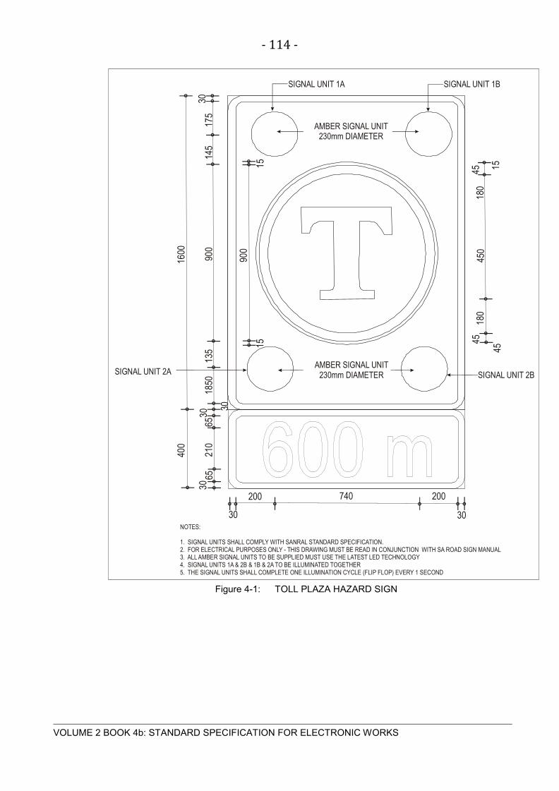
- 114 -
VOLUME 2 BOOK 4b: STANDARD SPECIFICATION FOR ELECTRONIC WORKS
Figure 4-1: TOLL PLAZA HAZARD SIGN
200
3065
210
6530
1850
135
30
15
900
900
145
175
30
15 154518
045
0
45
180
45
740 200
30 30
AMBER SIGNAL UNIT230mm DIAMETER
AMBER SIGNAL UNIT230mm DIAMETER
SIGNAL UNIT 2B
SIGNAL UNIT 1A SIGNAL UNIT 1B
400
1600
SIGNAL UNIT 2A
NOTES:
1. SIGNAL UNITS SHALL COMPLY WITH SANRAL STANDARD SPECIFICATION.2. FOR ELECTRICAL PURPOSES ONLY - THIS DRAWING MUST BE READ IN CONJUNCTION WITH SA ROAD SIGN MANUAL3. ALL AMBER SIGNAL UNITS TO BE SUPPLIED MUST USE THE LATEST LED TECHNOLOGY4. SIGNAL UNITS 1A & 2B & 1B & 2A TO BE ILLUMINATED TOGETHER5. THE SIGNAL UNITS SHALL COMPLETE ONE ILLUMINATION CYCLE (FLIP FLOP) EVERY 1 SECOND

- 115 -
VOLUME 2 BOOK 4b: STANDARD SPECIFICATION FOR ELECTRONIC WORKS
S E C T ION 5 P HY S IC AL S E C UR IT Y B AR R IE R S

- 116 -
VOLUME 2 BOOK 4b: STANDARD SPECIFICATION FOR ELECTRONIC WORKS
5.1 V E HIC L E B OOMS
High speed booms with a good track record are required at designated positions as shown on
the layout drawings.
5.1.1 Scope
The contractor shall be responsible for the design, shuttering and casting of the boom plinths,
complete with cage bolts, power and signal sleeves, unless otherwise stated.
5.1.2 General
The vehicle booms shall comply with the following specifications:
5.1.2.1 The mounting base shall be hot dip galvanized. The base shall be fastened to the 500mm deep
concrete plinth by means of 10 X 200mm chemical anchors.
5.1.2.2 The boom housing shall be manufactured from 3CR12 brushed stainless steel, white powder
coated, or as specified
5.1.2.3 The barrier enclosures shall be of sufficient internal dimensions to accommodate the equipment
envisaged:
a) Drive mechanism and spring assembly
b) Interface to control network, for remote control of the barrier
c) Inductive loop controllers (Typical 4)
d) Overvoltage protection
e) Local 240 V AC mains isolator
f) Tamper switch
g) Klippon terminals and DIN rails for field wiring
5.1.2.4 The housing shall have a lockable access door to allow easy access to the equipment
compartment.
5.1.2.5 The mechanism shall be a robust precision mechanism fitted with sealed roller bearings inside
plummer blocks. A 230V continuous duty stepper motor shall be used for the closing action.
5.1.2.6 Durable rubber stoppers shall be used to stop the link arm in open and closed positions.

- 117 -
VOLUME 2 BOOK 4b: STANDARD SPECIFICATION FOR ELECTRONIC WORKS
5.1.2.7 The printed circuit motherboard supply side shall have twin Dehnguard/Dehngap overvoltage
protection devices on a DIN rail adjacent to the 5kA 10 A double pole supply circuit breaker.
5.1.2.8 The unit shall accommodate the inductive loop presence detector relay on DIN rail.
5.1.2.9 The control circuit shall be supplied by means of a 5kA 5 Amp single pole circuit breaker.
5.1.2.10 The motor power circuit shall be supplied by means of a 5 Amp 5kA single pole circuit breaker.
5.1.2.11 Boom arms shall be as specified and of standard dimensions and aluminium construction,
similar to:
a) 125 x 75 mm rectangular aluminium tube with red reflective tape on a white finish
b) 4,5 m long, 47mm x 90mm actagonal profile, white aluminium with red reflective tape
c) 6 m long, 47mm x 90mm actagonal profile, white aluminium with red reflective tape
5.1.2.12 The connection of the booms onto the swing arm shall be by means of PVC shear bolts or
similar safety mechanisms. The shear direction shall be in the direction of traffic.
5.1.2.13 Balancing of the boom arm shall be accomplished by adjusting the built-in springs and rubber
buffers for boom dampening
5.1.2.14 When the power supply is interrupted, the boom shall be raised automatically. Re- closing shall
only commence after the local reader controller is on-line.
5.1.2.15 An adjustable exit delay shall close the boom after a period of 30 to 90 seconds, if no exit signal
was processed.
5.1.2.16 Two inductive loops shall be required, one “safety” loop and one “exit” loop per boom. Loops
shall be cut into the road surface and sealed with an approved “highway joint sealant”. No
section of the conductors shall be visible.
5.1.2.17 The Contractor shall supply and deliver two spare boom arms complete with four nuts per
vehicle boom.
5.2 P E R S ONNE L T UR NS T IL E S
5.2.1 Scope
The contractor shall be responsible for the design, supply and installation of the turnstile(s),
including shuttering and casting of the reinforced turnstile plinths, complete with cage bolts,
power and signal line sleeves.
5.2.2 General
The turnstiles shall comply with the following specifications:
- 118 -
VOLUME 2 BOOK 4b: STANDARD SPECIFICATION FOR ELECTRONIC WORKS
5.2.2.1 The turnstiles shall be configured to fail in a locked mode when the 12VDC control circuit supply
is removed.
5.2.2.2 The unit shall be suitable for outdoor use, IP54 rated and of mild steel polyurethane or powder
coated construction. The contractor shall be advised on the finish to be used.
5.2.2.3 The unit shall be factory fitted to accept the specified access control readers and CCTV
cameras. Wiring shall be concealed inside the vertical tubing structure. No wiring shall be
exposed.
5.2.2.4 A lockable mechanical override shall release the rotor and allow unidirectional rotation.
5.2.2.5 The 4-arm rotor shall rotate on maintenance-free sealed bearings. The rotor lock / release
action shall be done by means of linear motors. The mechanism shall be provided with bi-
directional shock absorbing buffers.
5.3 MOT OR IS E D DOOR S AND G AT E S
5.3.1 Roller shutter gates
5.3.1.1 Galvanized heavy duty chain link vehicle roller shutters will be motorized.
5.3.2 General
The following specifications for roller shutter gates are provided:
5.3.2.1 The mechanism shall be of robust industrial design complete with roller bearings and a 230V
geared motor for reliable operation. Motor rating shall exceed 0.75 kW. Thermal motor
protection shall be provided.
5.3.2.2 The control system shall employ limit switches and an emergency stop button.
5.3.2.3 A manually operated system to open and close the shutter during power outages shall also be
provided on the secure side of each roller shutter gate.
5.3.2.4 The gates shall be pad-lockable on the secure side.

- 119 -
VOLUME 2 BOOK 4b: STANDARD SPECIFICATION FOR ELECTRONIC WORKS
S E C T ION 6 R OADS IDE F IB R E OP T IC DAT A C OMMUNIC AT ION S Y S T E M

- 120 -
VOLUME 2 BOOK 4b: STANDARD SPECIFICATION FOR ELECTRONIC WORKS
6.1 S C OP E
6.1.1 This section covers the network design, supply, delivery and installation of fibre optic
cable/equipment.
6.2 S T ANDAR DS
6.2.1 All material/equipment shall comply with the relevant current SABS, BSI and/or IEC standards.
6.2.2 The following standards may be used as a guide but must not be regarded as a complete list:
• IEC 60793-1 : Optical fibres : Part 1 - Generic specification
• IEC 60793-1-1 : Optical fibres : Part 1 - Generic specification -
Section 1
• IEC 60793-1-4 : Optical fibres : Part 1 - Generic specification -
Section 4
• IEC 60793-2 : Optical fibres : Part 2 - Product specifications
• IEC 60794-1 : Optical fibre cables : Part 1 - Generic specification
• IEC 60794-2 : Optical fibre cables : Part 2 - Product specifications
• IEC 60794-3 : Optical fibre cables : Part 3 - Telecommunications
cables
• IEC 60869-1 : Fibre optic attenuators : Part 1 - Generic specification
• IEC 61073-1 : Splices for optical fibres and cables : Part 1 - Generic specification
6.3 F IB R E OP T IC C AB L E
6.3.1 The cable type and fibre count required in each section of the fibre optic network is dependent
on the type of installation and will be selected by the Contractor after consultation with the
Employer.
Table 6-1: GEOMETRIC CHARACTERISTICS
Cladding diameter 125 µm
Core/cladding concentricity error < 1.5 dB/km
Cladding non-circularity < 0.28 dB/km
Coating diameter 1100 – 1280 nm
Coating concentricity 9.2 ± 0,5 µm
Coating non-circularity 1300 – 1325 nm
- 121 -
VOLUME 2 BOOK 4b: STANDARD SPECIFICATION FOR ELECTRONIC WORKS
6.3.2 Insulation
6.3.2.1 The insulation material shall comprise of PVC in accordance with the latest edition of SABS
1411: Part II.
6.3.3 Bedding
6.3.3.1 The bedding shall consist of a continuous PVC extruded sheath.
6.3.4 Armouring – (where specified)
6.3.4.1 The armouring shall consist of one layer of round galvanised steel wire complying with the
requirements of the latest edition of SABS 1411: Part VI
6.3.5 Serving
6.3.5.1 An impermeable PVC outer sheath complying with the latest edition of SABS 1411: Part II shall
be provided.
6.3.6 Cable Drums
6.3.6.1 The cable drums shall be capable of taking a round spindle and be lagged with strong, closely
fitted battens, at the inner and outer circumference so as to prevent damage to the cables. The
spindle bearing plates shall be steel. The dimensions of the drum shall not exceed 1 100-mm
width, 2 000-mm diameter and the spindle bearing plate shall not be less than 9 mm thick. Each
drum shall be clearly marked on both sides in accordance with the latest edition of SABS 1507.
6.3.6.2 Suitable protective caps shall be fitted to the exposed ends of the optical fibre cable to avoid
penetration of moisture. Each cable drum shall be numbered. End caps should be handled
carefully to avoid damage during installation, and any damage caps should be replaced.
6.4 F IB R E OP T IC C AB L E INS T AL L AT ION
6.4.1 Cable Minimum Bending Radius
6.4.1.1 Irrespective of the type of installation and cable, it shall be ensured that the minimum bending
radius - as prescribed by the cable manufacturer – is never exceeded during handling and
installation. In general the minimum bending radius for a fibre optic is as follows:
Right angles : 12 – 14 times the cable outer diameter
Coiling : 25 times the cable outer diameter
- 122 -
VOLUME 2 BOOK 4b: STANDARD SPECIFICATION FOR ELECTRONIC WORKS
6.4.2 Installation in Trench
6.4.2.1 The installation in trench and the trench specification shall be as per the Specification for low
voltage power cables.
6.4.2.2 When the trench is filled, compacting machinery shall be employed only when coverage of the
cable is at least 300mm deep.
6.4.2.3 It shall be ensured that the maximum allowable pulling force as prescribed by the cable
manufacturer is never exceeded during installation.
6.4.3 Installation in Sleeves
6.4.3.1 It shall be ensured that the maximum allowable pulling force as prescribed by the cable
manufacturer is never exceeded during installation.
6.4.4 Vertical Installations and or Cable Rack/Ladder
6.4.4.1 It shall be ensured that the maximum unsupported length as prescribed by the cable
manufacturer, is never exceeded.
6.4.5 Overhead Installations
6.4.5.1 Only purpose-made reinforced aerial fibre cable shall be employed for overhead lines. The
maximum span and deflection as prescribed by the cable manufacturer shall never be
exceeded.
6.4.6 Marking of Cables and Cable Routes
6.4.6.1 The marking of the cables and cable routes shall be as per the Standard specification for the
labelling of power cables.
6.5 J OINT S / F US ION S P L IC ING
The installation of fusion splices shall be compliant with the following:
6.5.1 All splicing shall be of the fusion splice type and no mechanical splices are to be used.
6.5.2 A maximum splice insertion loss of 0.3dB per splice shall be allowed.
6.5.3 All fusion splices shall be done in splice enclosures of the correct type and size suitable for the
environment and specific installation and shall have a warning label affixed unto the outside
cover.
6.5.4 All splice joints shall have a splice protector over them.
6.5.5 All splice enclosures shall have a record sheet/label inside denoting the planning and use of the
fibres according to colour coding and/or numbering. Furthermore, this shall be dated and
- 123 -
VOLUME 2 BOOK 4b: STANDARD SPECIFICATION FOR ELECTRONIC WORKS
labelled according to areas and/or signals in use. A detailed plan of all splice enclosure
locations, and their detail, shall be submitted.
6.6 OP T IC AL F IB R E C ONNE C T OR S
6.6.1 All optical fibre ends shall be terminated to a cylindrical ferrule connector similar to the straight
tip (ST) type connector or equal and approved by the Employer.
6.6.2 All connectors shall be supplied with end caps protecting the connector against moisture and
dust or damage.
6.6.3 All pigtail connecting cables shall be supplied in a minimum length of 3 meter or as specified in
the detail specification.
6.6.4 A maximum insertion loss of 0.5dB per connector shall be allowed.
6.7 INT E R F AC E E QUIP ME NT
6.7.1 The optical fibre installation shall include all fibre to copper interface units to allow for
communication between field and local networks.
6.7.2 Termination conversion equipment shall be “Telest” or similar and approved 19-inch rack mount.
6.7.3 The equipment shall have “fine” over voltage protection equipment in series with the external
power supply.
6.7.4 Each fibre driver comprising eight channels or more shall be installed with a cable management
brush panel below the unit.
6.7.5 All cable connectors shall be labelled as specified in this document.
6.7.6 Unless specified to the contrary, each driver will be installed with a 19-inch rack mount UPS
unit.
6.7.7 The UPS unit shall provide a minimum of 20 minutes of power backup to the driver/drivers in the
cabinet.
6.7.8 The UPS unit shall be MGE Pulsar, APC or Masterguard Series A-19 true on-line double
conversion units or similar and approved units.
6.8 T E S T ING AND C OMMIS S IONING
6.8.1 The contractor shall provide all equipment, instrumentation and supplies necessary to perform
site testing and commissioning.
6.8.2 Original copies of all data produced, including results of each test procedure shall be submitted
to the Employer at the conclusion of each phase of testing.

- 124 -
VOLUME 2 BOOK 4b: STANDARD SPECIFICATION FOR ELECTRONIC WORKS
6.8.3 During the testing and commissioning period, the contractor shall identify failures, determine
causes of failures and deliver a written report to the Employer detailing the nature of each failure
the corrective action taken, results of tests performed and shall recommend when testing should
be resumed.
6.8.4 Optical Fibre LAN Tests
6.8.4.1 Optical Time Domain Reflectometer (OTDR) Tests
OTDR tests shall be performed on each section of the optical fibre network indicating any optical
fibre breaks or splice losses and a printout report shall be submitted to the Employer for
approval before acceptance of the installation.
The contractor shall provide all equipment, instrumentation and supplies necessary to perform
the required site testing and commissioning.
Original copies of all data produced, including results of each test procedure shall be submitted
to the Employer at the conclusion of each phase of testing.
6.8.4.2 Power Meter and Light Source Tests (PMLS)
PMLS tests shall be performed on each section of the optical fibre network and a printout report
shall be submitted to the Employer for approval before acceptance of the installation.
The contractor shall provide all equipment, instrumentation and supplies necessary to perform
site testing and commissioning.
Original copies of all data produced, including results of each test procedure shall be submitted
to the Employer at the conclusion of each phase of testing

- 125 -
VOLUME 2 BOOK 4b: STANDARD SPECIFICATION FOR ELECTRONIC WORKS
S E C T ION 7 F IR E DE T E C T ION S Y S T E M

- 126 -
VOLUME 2 BOOK 4b: STANDARD SPECIFICATION FOR ELECTRONIC WORKS
7.1 S C OP E
The section provides guidelines for the supply and installation of a fully automatic fire detection
system.
7.2 S T ANDAR DS
7.2.1 The system design, manufacture, installation and testing procedures shall comply with:
• Detection SANS 10139 : 2007
• System components SANS 50054
• System triggering SANS 396 parts 1 & 2
• The OHS Act (Act no 85 of 1993)
• Building Guidelines SANS 10400
7.3 G E NE R AL
7.3.1 This specification covers supply, installation, system interface, testing, commissioning
guarantee and maintenance of new fire detection system. The works shall broadly consist of
and not necessarily limited to the following:
a) Installation of an Analogue Addressable Fire Panel with software and graphical user
interface.
b) Installation of smoke detectors on ceilings and in ceiling and floor voids.
c) Installation of wall-mounted fire break glass units.
d) Supply and installation of control and power cabling as required.
e) Supply and installation of lift and HVAC interface equipment.
f) Compilation of the graphic user interface
g) Site test and commissioning.
h) As built drawings and operating manuals.
i) Maintenance and repair during the 12 months defects liability period.
7.3.2 The system shall be similar and equal approved to the Ziton or GE fire detection equipment.

- 127 -
VOLUME 2 BOOK 4b: STANDARD SPECIFICATION FOR ELECTRONIC WORKS
7.3.3 The system shall operate in accordance to the configuration drawings supplied by the design
Engineer.
7.4 S MOK E DE T E C T OR S AND L INE IS OL AT OR S
7.4.1 These shall be similar or equal approved to the XP95 series of optical smoke detectors with low
profile bases to measure smoke density.
7.4.2 Rate-of-rise detectors shall be intelligent addressable devices rated at 58ºC and shall have rate-
of-rise element rated at 9.4ºC per minute.
7.4.3 Each loop shall be provided with two short circuit isolators.
7.4.4 All detectors shall have red led indication switched from the fire control panel upon activation
7.5 B AT T E R IE S /UP S P OWE R
7.5.1 Where batteries are used, these shall be 17 A.hr sealed Gel Cell type.
7.5.2 The fire alarm system shall be supplied with UPS power
7.6 MANUAL C AL L P OINT S
7.6.1 The call points shall be manufactured from self-extinguishing red polycarbonate plastic
7.6.2 Manual call points shall comply with BS5839 part 2.
7.6.3 The overall size of the call point shall not exceed 100 mm x 100 mm x 60mm.
7.6.4 The call point shall be based upon a standard product manufactured by a reputable call point
manufacturer. It shall consist of an enclosure with captive glass pane, and it shall incorporate an
addressable communications module. Breaking the pane shall initiate an alarm. The call point
shall incorporate a plastic – laminated safety glass, which will not produce sharp edges when
broken.
7.6.5 An externally visible red LED shall be incorporated to indicate when the device is in alarm. This
led will be switched by the fire control panel.
7.6.6 The word “FIRE” shall appear in black letters across the top of the call point.
7.6.7 Each call point shall be uniquely addressed as a single element on the main fire control panel.
7.7 C OMB INE D S OUNDE R AND S T R OB E L IG HT
7.7.1 These units shall be low profile and similar and equal approved to the Series XP 95 alarm
devices.
7.7.2 The units shall be installed in all positions as indicated on the layout drawings.

- 128 -
VOLUME 2 BOOK 4b: STANDARD SPECIFICATION FOR ELECTRONIC WORKS
7.7.3 It shall be possible to adjust the tone and volume of the sounder.
7.7.4 The power supply wiring shall from part of this contract.
7.7.5 The audible/visual combination alarm device shall have an ingress protection of at least IP65.
7.8 C ONT R OL P ANE L
7.8.1 The supervisory (global) fire alarm panel shall be located in the designated location in
accordance to the Fire system layout drawings.
7.8.2 Interface with other building systems
7.8.2.1 The fire control panel shall integrate, where applicable but not limited to, with the following:
a) BMS system
b) GSM building health remote alert module
c) Numerous HVAC control panels
d) Smoke control door magnets
e) Smoke purging fans
f) Fire dampers inside air conditioning ducting
g) Passenger elevators
h) Direct radio link to the designated fire station.
7.8.3 Conduit and ducting
7.8.3.1 Cabling shall be of the 0.8mm2 2-pair fire resistant cable to BS 4066-1/3, 6425, 7622 and 6387
screen type.
7.8.4 Graphic user interface
7.8.4.1 Software shall be installed on the Fire Detection Server or nominated computer.
7.8.4.2 The Employer will provide the floor layouts to the Subcontractor in Autocad format. The
Contractor will be responsible to add the loops, field elements, -addresses on the GUI.

- 129 -
VOLUME 2 BOOK 4b: STANDARD SPECIFICATION FOR ELECTRONIC WORKS
S E C T ION 8 G AS F IR E S UP P R E S S ION S Y S T E M

- 130 -
VOLUME 2 BOOK 4b: STANDARD SPECIFICATION FOR ELECTRONIC WORKS
8.1 S C OP E
8.1.1 Autonomous gas fire suppression systems may be installed in several mission critical locations.
Possible locations include:
• Server rooms
• Plant rooms housing UPS, LV, HV or generators
• Archive rooms
8.2 S T ANDAR DS
8.2.1 The system design, manufacture, installation and testing procedures shall comply with SANS
1450 parts 1 to 12
8.3 G E NE R AL
8.3.1 Where ceiling and floor voids are present, these will be zoned separately from the main room
area.
8.3.2 Extinguishing Agent
8.3.2.1 Contractors shall base their tender submissions on the gas as specified in the bill of quantities.
8.3.3 Piping
8.3.3.1 Threaded, Schedule 40, seamless steel pipe with steel supports at 500mm centre to centre shall
be used for the gas distribution.
8.3.4 Gas control units
8.3.4.1 Gas control units similar and equal approved to Ziton or GE dedicated gas control units shall be
used; one per room
8.3.5 Triggering Circuitry
8.3.5.1.1 Contractors shall allow for a local energy source at each gas-protected room to supply the
triggering circuit for the detonators. Full details of the power source shall be provided with the
submission. Source capacity shall exceed 15 A.hr.

- 131 -
VOLUME 2 BOOK 4b: STANDARD SPECIFICATION FOR ELECTRONIC WORKS
S E C T ION 9 F IR E T E L E P HONE S Y S T E M

- 132 -
VOLUME 2 BOOK 4b: STANDARD SPECIFICATION FOR ELECTRONIC WORKS
9.1 G E NE R AL
9.1.1 Fire telephones are required in the positions as indicated on the drawings. The master station
will be situated in a central location as per the layout drawings.
9.1.2 The system configuration shall be as per the layout drawing
9.1.3 The back boxes for the fire telephones shall not exceed dimensions 216(w) x 356(h) x 89(d)
mm.
9.1.4 The fire telephone system shall be based on an Aiphone microprocessor controlled system or
similar and equal approved intercom system.
9.1.5 The system shall be supplied with UPS power.
9.1.6 All interconnection cable shall be 1.5mm2 fire resistant cable similar and equal approved to
Pirelli FP200 (FR20) with red outer sheath
9.2 OP E R AT ION
9.2.1 System operation shall be as follows; lifting the handset will register a call at the master station
via an audible and visual annunciation. Once the control room operator activates the intercom
button, duplex communication is established

- 133 -
VOLUME 2 BOOK 4b: STANDARD SPECIFICATION FOR ELECTRONIC WORKS
S E C T ION 10 WIR E L E S S DAT A C OMMUNIC AT ION S Y S T E M

- 134 -
VOLUME 2 BOOK 4b: STANDARD SPECIFICATION FOR ELECTRONIC WORKS
10.1 P UR P OS E OF INS T AL L AT ION
The purpose of the installation has been adequately covered in other parts of the tender
documentation, but can be summarised as follows for the purpose of this part of the
specification:
In order to function as intended, the proposed ATMS will be reliant on efficient data acquisition-
and control from and to field devices. Such data communication will be effected by different
means. These will include FO cabling, Cu data cabling, wireless transmission links- and area
networks between and around the different nodes in the network. Where possible and practical,
data communications will be FO based, but also wireless where cable based communication are
not possible. The purpose of this specification is to provide a generic specification for wireless
inter-node links, as well as node-centred LAN/WAN’s.
10.2 S C OP E OF WOR K
The services to be rendered in accordance with this specification are set out in detail in all the
constituent parts of the tender document, but can be summarised as the supply, delivery,
installation, commissioning, guarantee and operation of the following:
a) All microwave based inter-node point-to point Rx/Tx units
b) All wireless LAN/WAN access nodes
c) Antennas for the above in accordance with link budget predictions
d) RF Cabling and connections
e) IP interfaces and cabling to all equipment
f) Power supplies for all of the above
g) Earthing and surge protection at each installation point
h) Link budget calculations for each link and coverage area
i) Setup and configuration of all links, access points and associated routers
j) Training and documentation as specified.

- 135 -
VOLUME 2 BOOK 4b: STANDARD SPECIFICATION FOR ELECTRONIC WORKS
10.3 AP P L IC AB L E S T ANDAR DS , AP P R OV AL A ND F R E QUE NC Y B AND
10.3.1 All wireless equipment offered shall be type approved by ICASA. A certified copy of the
approval shall be submitted upon request. Other standards as set out in elsewhere in the tender
documents shall also apply.
10.3.2 All equipment shall be 802.11a/b/g/n compliant.
10.3.3 Equipment shall be configurable to operate in the 5.7/5.8GHz ISM band. All emission
regulations and requirements for this band shall be adhered to.
10.3.4 Equipment shall comply with international safety standards UL 60950, CAN/CSA-C22.2 No.
60950, IEC 60950, EN 60950, as a minimum.
10.4 DIS C R E P ANC IE S , C ONF L IC T S AND AMB IG UIT IE S
10.4.1 Any discrepancy or conflict between this specification and any aspect of one or more of the
standards as mentioned under 10.3 above, shall be brought to the notice of the Employer during
the tender period, or mentioned in the appropriate schedule of deviations. No claim based on
such discrepancies will be considered after awarding of the contract.
10.5 IDE NT IF IC AT ION
10.5.1 All node equipment shall be clearly marked and labelled prior to the handover in accordance
with a previously agreed ID system. The standard specification regarding labelling shall be
adhered to. All wiring shall be numbered in accordance with assembly drawings.
10.6 INS P E C T IONS AND T E S T S
10.6.1 All equipment to be supplied under this contract shall be works inspected by the Employer prior
to delivery. For the purpose of inspections, the equipment shall be set up in working order by
the Contractor, and all functional tests performed on the equipment in order to ensure
compliance with specified characteristics. These tests shall be witnessed by the Employer and
any faults or deviations discovered during the works tests shall be fully rectified before
transportation to site.
10.6.2 The following minimum tests shall be performed:
10.6.2.1 Radio Equipment:
a) RF output power into antenna, as specified.
b) Reflected power.
c) Frequency accuracy check.
d) Spurious radiation.
e) Receiver sensitivity check.

- 136 -
VOLUME 2 BOOK 4b: STANDARD SPECIFICATION FOR ELECTRONIC WORKS
Final inspections on all equipment will be performed on site, where at least the first four of the
above tests will be repeated. All test equipment shall be provided by the Contractor.
It must be stressed that the equipment as specified, shall be connected up and tested as a
system prior to shipment to site. Partial acceptance or testing shall not be acceptable. All tests
and calibration certificates generated by the Contractor, or any of his specialist suppliers, shall
be submitted to the Employer for approval and subsequently included in the As Built manuals.
10.6.3 After installation, all elements of the system shall be fully and comprehensively tested on site,
prior to final commissioning and handover.
10.7 G UAR ANT E E P E R IOD, MAINT E NANC E AND S P AR E S
10.7.1 The Contractor shall fully guarantee and maintain all equipment supplied under this Contract for
a minimum period of 12 months, commencing on the date of acceptance of the complete
installation. Any equipment failure during the guarantee period, shall be promptly attended to.
10.7.2 A list of recommended spares shall be submitted to the Employer at the time of commissioning.
10.8 OP E R AT IONAL AND MAINT E NANC E MANUAL S
10.8.1 The Contractor shall provide 2 complete sets of manuals for all the systems and subsystems to
be provided in terms of their Contract. First handover of the system will not be taken until this
requirement has been met.
10.8.2 Hardware manuals shall be sufficiently detailed to enable maintenance personnel to attend to
first line maintenance functions. Drawings shall cover at least all aspects of physical
subsystem assembly, wiring diagrams and terminal connections. A list of suggested spares, as
well as required test equipment, is required.
10.8.3 Operational manuals shall cover ALL aspects of system startup, setup and operation.
Instructions shall be clearly understandable by a reasonably skilled operator.
10.9 T R AINING
10.9.1 The Contractor shall be required to train supervisory personnel of the Employer in the proper
operation of the system. A total of 2 people will attend this (these) training session(s). Training
shall include complete and in depth familiarisation with the new microwave equipment and
configuration thereof.
10.10 P OINT - T O – P OINT (P T P ) L INK S
10.10.1 General
Two types of PTP link could be utilised, depending on required throughput for the particular
section:
a) Medium speed, up to 300 Mbps

- 137 -
VOLUME 2 BOOK 4b: STANDARD SPECIFICATION FOR ELECTRONIC WORKS
b) High speed, up to 1 Gbps
10.10.2 Each terminal end shall consist of the following main components:
• Cabinet
• Power Supply
• Earthing
• Antenna Mast
• Mounting Materials
• Transient Protection
• Radio Equipment
These items are further described in subsequent paragraphs.
10.10.3 Cabinet
10.10.3.1 All terminal equipment must be mounted in a high impact resistant polycarbonate; fibreglass or
3CR12 steel cabinet suitable for external use. Steel cabinets must be epoxy powder coated in a
suitable approved colour and be equipped with a lockable door. The cabinet must be properly
sealed against dust and moisture. All cables entering the cabinet should be glanded off onto the
cabinet.
10.10.3.2 The cabinet must be mast mounted, or against any other structure. No overheating of
equipment must occur inside the cabinet.
10.10.3.3 Full workshop drawings of the proposed panel layout and construction shall be submitted for
approval prior to manufacture.
10.10.4 Power Supply
10.10.4.1 All terminal equipment shall be powered from a 230 VAC 50Hz power source. A suitable
internal power supply for the link unit must be provided, fed from the abovementioned mains
supply. This supply must be battery backed and have sufficient standby capacity for a supply
interruption of 6 hours min. Details of power consumption and battery capacity shall be given in
the appropriate schedules. Batteries must be of the maintenance free, sealed transient
protected type.
10.10.5 Communications Node Earthing
10.10.5.1 A proper earth connection shall be provided at each node. A 3m length of 70mm2
bare Cu
conductor shall be laid in a trench, approximately 700 deep, with a 1500 long Cu clad earth
spike at both ends. The communication unit earth and TSP circuitry shall be bonded on to this

- 138 -
VOLUME 2 BOOK 4b: STANDARD SPECIFICATION FOR ELECTRONIC WORKS
main earth with a 50mm2
Cu conductor. All lugs, nuts and bolts shall be brass, or cad plated.
Upon completion, the earth resistance shall be checked and if > 3 Ohm, and referred to the
Employer for further instructions regarding extension of the earthing installation. The entire
installation shall also be bonded on to any steel structure available at the particular point. A 10
mm2
bare Cu cable shall also be run with the antenna cable and bonded on to the
communication node earth point. The node earth point shall be bonded to the main earth bar
with a 70 mm2 bare Cu earth conductor.
10.10.6 Antenna Mast
10.10.6.1 Where masts are required, antenna masts must be similar and equivalent to a Webb ACP
50/3/5 and fitted to the side of the building or steel structure, with the necessary offset brackets
and mounting hardware. These masts must be earthed as specified, elsewhere in this
document. It will be attempted to mount antennas on available structures as far as possible and
in such a case, antennas shall be mounted on offset brackets on to the structures.
10.10.7 Mounting Materials
10.10.7.1 The antennas shall be supplied complete with mounting arms, clamps and support. All
mounting materials shall be heavy duty galvanised steel, stainless steel, or aluminium.
10.10.8 Transient and Surge Protection
10.10.8.1 The supply and installation of lightning and surge protection equipment forms part of this
contract.
10.10.8.2 The Contractor shall supply and install all the necessary lightning protectors, arresters and other
devices to provide protection for people and equipment on the premises.
10.10.8.3 Surge arresters shall be provided on all phases at the input terminals to each equipment
cabinet.
10.10.8.4 All mains lightning arresters shall comply with the requirements of SANS 171 and shall bear the
SABS mark. Mains lightning protection devices shall have the following minimum specification:
a) 6kV (1,2/50 uS waveform)
b) 6kA (8/20 uS waveform)
c) 120 Joules
10.10.8.5 The ground terminal of each arrester shall be solidly strapped to the earth bar in the distribution
board or cabinet by means of an appropriate copper strap.
10.10.8.6 Careful attention shall be paid to the common bonding of all earth terminals and bars in the
installation to achieve the required degree of protection.

- 139 -
VOLUME 2 BOOK 4b: STANDARD SPECIFICATION FOR ELECTRONIC WORKS
10.10.8.7 All input and output circuits shall be suitable for connection to the control cables. As high
voltage spikes can occur on the cables, the input and output circuits shall include adequate
protection against these spikes. The circuit shall be designed to cope with a 6 kV, 1/50
microsecond impulse (1 Joule) repeated 20 times per burst of impulses in a short period of time
(of the order of 20 seconds). Impulse current handling capability shall be 3kA minimum for an
8/20 uS waveform. The protection level offered by the equipment is to be quoted, giving level
and rise/fall times of spikes to which the equipment is impervious by virtue of the built-in
protection.
10.10.8.8 Where external lines have to interface with sensitive electronic equipment, such as computers
and associated peripheral equipment, suitable opto-isolators with an isolation level of at least
5kV shall be employed, apart from the protection measures as mentioned earlier.
10.10.8.9 All CCTV and RF coaxial cables shall be provided with in-line surge suppressors, with
specifications as per 11.7 above. RF surge protection equipment shall be in-line Polyphaser IS-
50NX-CO, or equivalent and ¼ wave stub. The co-ax protection must be properly earthed on to
the main site earth with a 10mm2 Cu earth.
10.10.8.10 It is the responsibility of the Contractor to indicate what steps have been taken to adequately
protect the entire installation against any damages that may be caused by lightning and static
discharges.
10.10.8.11 All I/O connections shall be protected against transients with equipment complying with the
conditions set out above. Suitable devices are obtainable from Messrs. Surgetek or Electro-
Phoenix in Johannesburg.
10.10.9 Terminal Node Cabling
10.10.9.1 RF cabling shall be similar and equivalent to LMR900 low loss cable, or better. All cabling shall
be neatly run on masts and structures and be supported with cable ladders if longer than 0.5m.
Mast strapping shall be done with stainless steel banding.
10.10.9.2 All I/O wiring at the node shall be done with screened twisted pair wiring of 0,5 mm2
minimum,
conductor area. Single core wiring shall not be used. All wiring to be neatly routed in plastic
slotted ducting with snap on covers. All wiring shall be marked and numbered to correspond
with the information on as-built drawings, to be prepared as part of this Contract.
10.10.10 Medium Speed Link Radio Equipment:
10.10.10.1 The radio equipment shall consist of the receiver, exciter and integrated 2x2 24 dBi dual
polarized MIMO antenna. The specification of the radio is as follows:
Table 10-1: MEDIUM SPEED LINK RADIO SPECIFICATIONS
Parameter Specification
Frequency Band 5.7/5.8 GHz.
Effective Data rate 300 Mbps

- 140 -
VOLUME 2 BOOK 4b: STANDARD SPECIFICATION FOR ELECTRONIC WORKS
RF output power (Into Antenna) +18 dBm
Ambient temperature range -20° C to +60° C
Output impedance: 50 Ohm
Output protection Output circuits protected against open or short circuit operation of RF output port and shall be self restoring
Rating Continuous
Sensitivity - 85 dBm for BPSK, at BER 1 x 10e-6
Modulation OFDM with BPSK, QPSK, QAM16, QAM64
Data latency < 3mS
Data ports Two auto MDI-X RJ45 10/100/1000Mbps Ethernet
Equipment class Carrier Grade
Remote management Telnet and SSH, Web GUI and SSL, TFTP, SNMPv3
Environmental Full water and dustproof to IP67
Generic type: Proxim QB8100 series, or similar and equivalent as approved
10.10.11 High Speed Link Radio Equipment:
10.10.11.1 The radio equipment shall consist of the receiver, exciter and integrated 41 dBi 13” parabolic
antenna. The specification of the radio is as follows:
Table 10-2: HIGH SPEED LINK RADIO SPECIFICATIONS
Parameter Specification
Frequency Band 60 GHz
Effective Data rate 1 Gbps full duplex
RF output power (Into Antenna) 10 mW
Ambient temperature range -20° C to +60° C
Output impedance: 50 Ohm
Output protection Output circuits protected against open or short circuit operation of RF output port and shall be self restoring.
Rating Continuous
Sensitivity - 80 dBm for BPSK, at BER 1 x 10e-12
Modulation BPSK
Data latency < 50uS
Data ports Two 1000 Base-SX Mbps Ethernet
Equipment class Carrier Grade
Remote management Full web and SNMP enabled
Environmental Full water- and dustproof to IP67
Generic type: Bridgewave AR60 series, or similar and equivalent as approved

- 141 -
VOLUME 2 BOOK 4b: STANDARD SPECIFICATION FOR ELECTRONIC WORKS
10.10.12 LAN / WAN ACCESS POINT EQUIPMENT
10.10.12.1 General
Paragraphs 10.10.3 - 10.10.9 above will also be applicable to the LAN / WAN equipment
10.10.12.2 The specification of the LAN/WAN equipment is as follows:
Table 10-3: LAN/WAN ACCESS POINT SPECIFICATIONS
Parameter Specification
Frequency Band 5.7/5.8 GHz.
Effective Data rate 300 Mbps
Standard 802.11a/b/g/n
RF output power (Into Antenna) +9.5 dBm (For 802.11n)
Antenna 3x3 Patch type MIMO
Ambient temperature range -20° C to +60° C
Output impedance: 50 Ohm
Output protection Output circuits protected against open or short circuit operation of RF output port and shall be self restoring.
Rating Continuous
Sensitivity - 85 dBm for BPSK, at BER 1 x 10e-6
Modulation OFDM with BPSK, QPSK, QAM16, QAM64
Data ports RJ45 10/100/1000Mbps Ethernet
Equipment class Carrier Grade
Remote management Telnet and SSH, Web GUI and SSL, TFTP, SNMP
Environmental Full water and dustproof to IP67
Generic type: Proxim AP-8000 series, or similar and equivalent as approved
10.10.13 MICROWAVE /ISM BAND ANTENNAS
10.10.13.1 General
The antennas will be suited for the respective link frequency bands. The gains of the antennae
shall be matched to the application and calculated link budget. Patch, solid parabolic and grid
antennas are acceptable, depending on the required gain. Antennas shall comply with the
following:
10.10.13.2 Patch Antennas
Patch antennas shall comply with the following:

- 142 -
VOLUME 2 BOOK 4b: STANDARD SPECIFICATION FOR ELECTRONIC WORKS
Table 10-4: MICROWAVE/ISM BAND ANTENNA SPECIFICATIONS
Parameter Specification
Gain 8.5 dBi omni, 14 dBi directional (-3 dB points +-45˚), 17 dBi directional (-3 dB points +-32˚)
Gain VSWR < 2.0:1
Feed power handling 10 W
Nominal input impedance 50 Ohm (N-type connector)
Frequency 5.7 – 5.8 GHz
Polarisation Linear (V/H)
Survival wind speed 160 kmh
Enclosure IP65
Generic type Poynting, Aircom, Wavion, or similar as approved
10.10.14 Solid Parabolic Antennas
Solid parabolic antennas shall comply with the following specifications:
Table 10-5: SOLID PARABOLIC ANTENNA SPECIFICATIONS
Parameter Specification
Polarization Linear, field adjustable for horizontal or vertical polarization
Material Aluminium reflector and pipe mount
Mounting hardware Galvanized and/or stainless steel
Adjustment Provision for fine azimuth and elevation adjustment
Impedance 50 Ohm (FM N-type connector)
Gain 28 -34 dBi
F/B ratio 38 dB
VSWR 1.5:1
Survival wind speed 200 kmh
Generic type mWave 5.725-5.850 RP2-58-N, or similar as approved

- 143 -
VOLUME 2 BOOK 4b: STANDARD SPECIFICATION FOR ELECTRONIC WORKS
10.10.15 Grid Parabolic Antennas
Grid parabolic antennas shall comply with the following specifications:
Table 10-6: SOLID PARABOLIC ANTENNA SPECIFICATIONS
Parameter Specification
Polarization Linear, field adjustable for horizontal or vertical polarization
Material Cast aluminium reflector and pipe mount
Mounting hardware Galvanized and/or stainless steel
Adjustment Provision for fine azimuth and elevation adjustment
Impedance 50 Ohm (FM N-type connector)
Gain 27 dBi
F/B ratio 38 dB
VSWR 1.5:1
Survival wind speed 200 kmh
Generic type mWave GS2-58-N 5.725-5.850, or similar as approved
10.10.16 LICENSED MICROWAVE LINKS
10.10.16.1 It is possible that the Contractor might want to offer a microwave link in one of the licensed
bands. The specification will obviously depend upon the exact requirements of the particular
link, however the following general specifications shall apply:
10.10.16.2 The path link budget and fade margin, shall be calculated in accordance with 10.10.17 below.
10.10.16.3 High capacity Ethernet transport with embedded L2 switch
10.10.16.4 E1/T1 operation, soft configurable up to NxE1, depending on bandwidth, but shall typically be
capable of 75xE1 over a 28 MHz carrier bandwidth.
10.10.16.5 Software configurable for traffic routing and setup
10.10.16.6 Will support QPSK, 16QAM, 32QAM, 64QAM and 128 QAM modulation without hardware
change.
10.10.16.7 Full remote diagnostic and setup capability
10.10.16.8 Capable of Ethernet, or SDH
10.10.16.9 Frequency range: 6-30 GHz
10.10.16.10 Typical Receiver sensitivity for 16QAM operation and BER = 1x10⁻⁶
:
6 GHz range: -86 dBm

- 144 -
VOLUME 2 BOOK 4b: STANDARD SPECIFICATION FOR ELECTRONIC WORKS
8 GHz range: -85 dBm
11 GHz range: -84 dBm
10.10.16.11 Typical transmitter output for 16QAM operation:
6-8 GHz: +26.5 dBm
11 GHz: +22 dBm
10.10.16.12 It shall be the responsibility of the Contractor to apply for the necessary ICASA licensing and to
pay all associated fees, including annual license fees.
10.10.16.13 Outdoor units shall be IP67 protected
10.10.17 LINK BUDGET AND SYSTEM OPERATING MARGIN CALCULATION
It shall form part of the Contractor’s contract to ensure that all networks designed, installed and
operated by him, shall have a minimum Systems Operating Margin (SOM) of 10 dB, where the
SOM is calculated as:
SOM = PTX + GTX – LTX – LFS – LM – LR + GRX – LRX - SRX
where:
• SOMRX = system operating margin at receiver (dBm)
• PTX = transmitter output power (dBm)
• GTX = transmitter antenna gain (dBi)
• LTX = transmitter losses (coax, connectors, etc) (dB)
• LFS = free space loss or path loss (dB)
• LM = miscellaneous losses (ie. additional fade margin, body loss, polarization
mismatch, etc.) (dB)
• LR = Precipitation losses, ie. rain, fog (dB)
• GRX = receiver antenna gain (dBi)
• LRX = receiver losses (coax, connectors, etc) (dB)
• SRX = receiver sensitivity (dBm)

- 145 -
VOLUME 2 BOOK 4b: STANDARD SPECIFICATION FOR ELECTRONIC WORKS
10.10.18 EFFECTIVE THROUGHPUT MARGIN
10.10.18.1 General
It shall be the Contractor’s responsibility to ensure that the correct amount of network hardware
is allowed for and configured accordingly, to ensure the Network Topology and Network
Bandwidth requirements are met. It is also required that a conservative approach be followed in
this process. To this effect, the following guidelines shall be followed:
10.10.19 ISM Band Equipment
In the case of ISM band equipment, ie. IEEE 802.11a/b/g/n and 802.15.xx, effective available
throughput utilisation of any network subsystem shall not exceed 35% of the specified maximum
throughput indicated by the corresponding IEEE standard. (eg. The 802.11g available
throughput of 54Mbit/s shall be derated to 18 Mbps). The remaining portion shall be considered
as network overhead.
10.10.20 Licensed Microwave Links
In the case of licensed links, the maximum utilisation shall not exceed 80% of the capacity as
specified by the manufacturer.
10.10.21 Design Calculations
The Contractor shall be required to provide proof of his calculations in respect of the above,
prior to any installation commencement on site.
10.10.22 Schedule of Information on Equipment Offered
PTP Equipment (Medium Speed)
1 Manufacturer
2 Model
3 Country of Origin
4 Channel bandwidth
5 Effective throughput
6 Tx output (dBm)
7 Rx sensitivity
8 Power supply requirement (V/VA)
9 Comms standard
10 Frequency band
11 Antenna gain
12 Antenna type

- 146 -
VOLUME 2 BOOK 4b: STANDARD SPECIFICATION FOR ELECTRONIC WORKS
PTP Equipment (Medium Speed)
13 Type of protection on RF feed
14 Modulation type
15 Data input/output protocol
16 Type/Qty of comms port
17 Remote management format
18 Compliant standard
19 Carrier grade Yes/No
20 Environmental protection
21 RF Surge protection
22 Type of RF cable
23 Link budget calc’s included and comply with minimum operating margin?
Yes/No
24 Datasheets included on all equipment offered? Yes/No
PTP Equipment (High Speed)
1 Manufacturer
2 Model
3 Country of Origin
4 Channel bandwidth
5 Effective throughput
6 Tx output (dBm)
7 Rx sensitivity
8 Power supply requirement (V/VA)
9 Comms standard
10 Frequency band
11 Antenna gain
12 Antenna type
13 Type of protection on RF feed
14 Modulation type
15 Data input/output protocol
16 Type/Qty of comms port
17 Remote management format

- 147 -
VOLUME 2 BOOK 4b: STANDARD SPECIFICATION FOR ELECTRONIC WORKS
18 Compliant standard
19 Carrier grade Yes/No
20 Environmental protection
21 RF Surge protection
22 Type of RF cable
23 Link budget calc’s included and comply with minimum operating margin?
Yes/No
24 Datasheets included on all equipment offered? Yes/No
WAN/LAN Equipment
1 Manufacturer
2 Model
3 Country of Origin
4 Channel bandwidth
5 Effective throughput
6 Tx output (dBm)
7 Rx sensitivity
8 Power supply requirement (V/VA)
9 Comms standard
10 Frequency band
11 Antenna gain
12 Antenna type
13 Type of protection on RF feed
14 Modulation type
15 Data input/output protocol
16 Type/Qty of comms port
17 Remote management format
18 Compliant standard
19 Carrier grade Yes/No
20 Environmental protection
21 RF Surge protection
22 Type of RF cable

- 148 -
VOLUME 2 BOOK 4b: STANDARD SPECIFICATION FOR ELECTRONIC WORKS
23 Link budget calc’s included and comply with minimum operating margin?
Yes/No
24 Datasheets included on all equipment offered? Yes/No
Licensed Microwave Link Equipment
1 Manufacturer
2 Model
3 Country of Origin
4 Channel bandwidth
5 Effective throughput
6 Tx output (dBm)
7 Rx sensitivity
8 Power supply requirement (V/VA)
9 Comms standard
10 Frequency band
11 Antenna gain
12 Antenna type
13 Type of protection on RF feed
14 Modulation type
15 Data input/output protocol
16 Type/Qty of comms port
17 Remote management format
18 Compliant standard
19 Carrier grade Yes/No
20 Environmental protection
21 RF Surge protection
22 Type of RF cable
23 Link budget calc’s included and comply with minimum operating margin?
Yes/No
24 Datasheets included on all equipment offered? Yes/No
Antenna Equipment Details
1 Manufacturer
2 Country of Origin

- 149 -
VOLUME 2 BOOK 4b: STANDARD SPECIFICATION FOR ELECTRONIC WORKS
Antenna Equipment Details
3 Models: Patch Omni: Gain
4 Patch Directional 1 Gain
5 Patch Directional 2 Gain
6 Other Gain
7 Other Gain
8 Other Gain
9 Models: Parabolic:
10 Directional 1 Gain
11 Directional 2 Gain
12 Directional 3 Gain
13 Other Gain
14 Other Gain
15 Other Gain
16 Datasheets included on all? Yes/No

- 150 -
VOLUME 2 BOOK 4b: STANDARD SPECIFICATION FOR ELECTRONIC WORKS
S E C T ION 11 WIR E L E S S VOIC E S Y S T E M

- 151 -
VOLUME 2 BOOK 4b: STANDARD SPECIFICATION FOR ELECTRONIC WORKS
11.1 S C OP E
This Specification defines the minimum technical requirements for radio equipment to be used in
Land Mobile Radio (LMR) services. LMR equipment shall operate in one of the authorised
frequency bands or frequencies, and transmit within the corresponding output power levels
given in 11.6
LMR equipment may be base stations used in fixed locations, mobile stations used in vehicles
or as transportable stations, or handheld portable stations that come with an external antenna or
an integral antenna. Applications may include speech and/or data communication, and may be
performed using the Integrated Digital Enhanced Network (iDEN) or Terrestrial Trunked Radio
(TETRA) technology (see 11.6).
11.2 L MR E QUIP ME NT DE S IG N
11.2.1 LMR Equipment shall be designed to meet the following basic objectives:
a) The equipment shall not be constructed with any external or readily accessible control
which permits the adjustment of its operation in a manner that is inconsistent with this
Specification.
b) The device shall be marked with the supplier/manufacturer’s name or identification
mark, and the supplier/manufacturer’s model or type reference. The markings shall be
legible, indelible and readily visible.
11.3 HE AL T H AND S AF E T Y
11.3.1 Where appropriate, the LMR equipment shall comply with the International Commission on Non-
Ionising Radiation Protection (ICNIRP) guidelines for limiting exposure to time-varying EMFs in
the frequency range up to 300 GHz.
11.3.2 It should be noted that compliance with any radiation safety standard does not by itself confer
immunity from legal obligations and requirements imposed by national health or safety
authorities.
11.4 T E C HNIC AL R E QUIR E ME NT S
11.4.1 The LMR Equipment shall comply with the RF output power and spurious emissions given in
Table 1, operating in its intended frequency band or frequencies. It shall fulfil the relevant
requirements of this Specification on all the permitted frequencies which it is intended to
operate.
11.5 S P E C IF IC AT IONS
11.5.1 Suppliers shall demonstrate that the LMR equipment has been tested and certified for
conformity with the applicable technical requirements stipulated in 11.6 of this Specification.

- 152 -
VOLUME 2 BOOK 4b: STANDARD SPECIFICATION FOR ELECTRONIC WORKS
Measurement methods and conditions shall be with reference to one of the following standards,
whichever is applicable for the equipment under test (refer to 11.6 for guidance):
ETSI EN 300 086-1
Electromagnetic compatibility and Radio spectrum Matters (ERM); Land Mobile Service; Radio
equipment with an internal or external RF connector intended primarily for analogue speech;
Part 1: Technical characteristics and methods of measurement
ETSI EN 300 296-1
Electromagnetic compatibility and Radio spectrum Matters (ERM); Land Mobile Service; Radio
equipment using integral antennas intended primarily for analogue speech; Part 1: Technical
characteristics and methods of measurement
FCC Part 90
Federal Communications Commission, Part 90 Private Land Mobile Radio Services
ETSI EN 300 113-1
Electromagnetic compatibility and Radio spectrum Matters (ERM); Land Mobile Service; Radio
equipment intended for the transmission of data (and/or speech) using constant or non-constant
envelope modulation and having an antenna connector; Part 1: Technical characteristics and
methods of measurement
ETSI EN 300 390-1
Electromagnetic compatibility and Radio spectrum Matters (ERM); Land Mobile Service; Radio
equipment intended for the transmission of data (and/or speech) and using an integral antenna;
Part 1: Technical characteristics and methods of measurement
ETSI EN 300 394-1
Terrestrial Trunked Radio (TETRA); Conformance Testing Specification; Part 1: Radio
ETSI EN 300 396-2
Terrestrial Trunked Radio (TETRA); Technical requirements for Direct Mode Operation (DMO);
Part 2: Radio aspects
ETSI EN 300 392-2
Terrestrial Trunked Radio (TETRA); Voice plus Data (V+D); Part 2: Air Interface (AI)

- 153 -
VOLUME 2 BOOK 4b: STANDARD SPECIFICATION FOR ELECTRONIC WORKS
ETSI EN 303 035-1
Terrestrial Trunked Radio (TETRA); Harmonised EN for TETRA equipment covering essential
requirements under article 3.2 of the R&TTE Directive; Part 1: Voice plus Data (V+D)
ETSI EN 303 035-2
Terrestrial Trunked Radio (TETRA); Harmonised EN for TETRA equipment covering essential
requirements under article 3.2 of the R&TTE Directive; Part 2: Direct Mode Operation (DMO)
11.5.2 Where appropriate, suppliers shall demonstrate the LMR equipment has been tested according
to measurement methods and limits for:
a) EMC emissions from the DC power or AC mains power input/output ports defined in ETSI
EN 301 489-1 or IEC CISPR 22; and
b) Electrical safety defined in the IEC 60950-1

- 154 -
VOLUME 2 BOOK 4b: STANDARD SPECIFICATION FOR ELECTRONIC WORKS
11.6 T E C HNIC AL R E QUIR E ME NT S F OR R ADIO E QUIP ME NT
Item Operating frequencies
Channel spacing
Max RF power output
Spurious emissions
Applications Additional requirements
1
80 MHz
12.5 kHz
Base/mobile:25W ERP
1
< 20nW
Portable: 5W ERP
Base, mobile or portable equipment for analogue speech
• Suppliers registering equipment for use in Private Radio Network operation are required to first seek the approval of ICASA on the frequencies to be used.
• Suppliers registering equipment for use in Public Radio Data Communication Networks are advised to check with Network Operations on the exact operating frequencies used.
• Operation under this provision requires ICSA licensing.
• Provision does not apply to equipment with special function such as tone coded squelch, selective calling decoders or encoders, which shall be disabled during testing.
150 MHz
450 MHz
900 MHz 25 kHz
2
Mobile Tx:
415 – 417 MHz
Base Tx:
425 – 427 MHz
12.5 kHz / 25 kHz Base: 25 W
ERP
Mobile: 25 W ERP
Portable: 5 W ERP
43 + 10log(P)
where P = Rated carrier power in Watts
Base, mobile or portable equipment for data
Mobile Tx:
806 – 818 MHz
Base Tx:
851 – 863 MHz
25 kHz
3 477 – 477.25
12.5 kHz 500 mW ERP < 2 nW Multi-channel portable radio equipment for analogue speech
• Frequencies specified in this provision are to be used on non-interference, non-protected and shared basis.
1 Effective Radiated Power (ERP) refers to a half wave tuned dipole, which is used for frequencies below 1 GHZ

- 155 -
VOLUME 2 BOOK 4b: STANDARD SPECIFICATION FOR ELECTRONIC WORKS
Item Operating frequencies
Channel spacing
Max RF power output
Spurious emissions
Applications Additional requirements
MHz (localised use)
• Provision does not apply to equipment with special function such as tone coded squelch, selective calling decoders or encoders, which shall be disabled during testing.
• Repeaters and amplifiers are not allowed to be used with the multi-channel portable radio equipment to extend the range of coverage.
• Equipment shall use integral antenna only, and be designed to ensure that no antenna other than that furnished by the responsible party shall be used.
• Equipment shall be equipped with the Continuous Tone Code Sub-audible Squelch (CTCSS) capability with a minimum number of 10 distinct tones out of 32 as specified in Annex A of this Specification.
4 446 – 446.1 MHz
12.5 kHz 500 mW ERP < 2 nW
Portable radio equipment for analogue speech
(localised use)
• Frequencies specified in this provision are to be used on non-interference, non-protected and shared basis.
• Provision does not apply to equipment with special function such as tone coded squelch, selective calling decoders or encoders, which shall be disabled during testing.
• Repeaters and amplifiers are not allowed to be used with the multi-channel portable radio equipment to extend the range of coverage.
• Equipment shall use integral antenna only, and be designed to ensure that no antenna other than that furnished by the responsible party shall be used.

- 156 -
VOLUME 2 BOOK 4b: STANDARD SPECIFICATION FOR ELECTRONIC WORKS
Item Operating frequencies
Channel spacing
Max RF power output
Spurious emissions
Applications Additional requirements
5 Tx: 806 – 825 MHz
25 kHz
Base/Mobile: 25 W ERP
Portable: 5 W ERP
43 + 10log(P)
where P = Rated carrier power in Watts
Base, mobile and portable equipment for iDEN trunked mobile radio system
• Operation under this provision requires ICASA licensing.
• If the iDEN equipment supports the GSM mode, suppliers shall demonstrate that equipment has been tested and certified to comply with the IDA TS GSM-MT.
• If the iDEN equipment supports WLAN mode, suppliers shall demonstrate that equipment has been tested and certified to comply with the relevant requirements for WLAN given in the IDA TS SRD.
6
380 – 400 MHz
25 kHz 25 W ERP
36 dBm in 100 kHz bandwidth in frequency range 9 kHz to 1 GHz
-30 dBm in 1 MHz bandwidth in frequency range 1 to 4 GHz
Base and mobile stations for TETRA trunked mobile radio system
• Operation under this provision requires ICASA licensing.

- 157 -
VOLUME 2 BOOK 4b: STANDARD SPECIFICATION FOR ELECTRONIC WORKS
S E C T ION 12 T E L E P HONY AND INT E R C OM S Y S TE MS

- 158 -
VOLUME 2 BOOK 4b: STANDARD SPECIFICATION FOR ELECTRONIC WORKS
12.1 T E L E P HONY
12.1.1 SCOPE
This specification covers the requirements for the telephony systems.
12.1.2 VOIP Phone system
12.1.2.1 Scope
Where the supply and installation of a VOIP phone system to provide voice services using the
buildings data infrastructure and to provide a voice mail system, the following requirements shall
be adhered to. The hardware may include a processing server, switches for line connections
and switching, Power over Ethernet switches, voice gateways for analogue and digital trunk
connections, patch cables and cabling.
Minimum requirements for this IP phone system are as follows:
• SIP Compliant
• Support IMAP email protocol
• IEEE 802.3af Power over Ethernet
• Unified messaging for up to 50 users, or as specified
• Standard voice mail for up to 50 users, or as specified
• Building Survivability
• UPS backup should be for a minimum of 30 minutes in each data closet
• Cabling for data and voice runs as needed
• All data systems platform and products must be Cisco, or equal and approved
equivalent
Data cabling, network configuration and layout shall comply with Section 2, Information and
communication technology specifications, where applicable.
12.1.2.2 Detail specifications
12.1.2.2.1 The IP Telephony System equipment shall be scalable in design and shall make provision for
future expansion.
12.1.2.2.2 The IP Telephony System must support Voice, Video, Data and mobile communication, or as
specified

- 159 -
VOLUME 2 BOOK 4b: STANDARD SPECIFICATION FOR ELECTRONIC WORKS
12.1.2.3 The proposed solution shall be a centrally managed system.
12.1.2.4 The system shall support direct-inward-dial (DID) and direct-outward dial (DOD) on BRI, PRI
and normal POTS port.
12.1.2.5 The proposed communications solution must be ready to support IPv6 to ensure that the
solution can be scaled for the future
12.1.2.6 The system shall support the following basic PABX Telephone feature:
a) Conference Call
b) Call Park
c) PSTN failover on automated alternate route
d) Call admission control base on WAN bandwidth
e) Call Forward / Call Waiting / Call Transfer
f) Calling Line Identification
g) Call coverage
h) Forwarding based on internal and external calls
i) Forwarding out of a coverage path
j) Timer for maximum time in coverage path
k) Time of day
l) Personal Directory
m) Redial List
n) Callers List etc.
o) Message Wait Indicator

- 160 -
VOLUME 2 BOOK 4b: STANDARD SPECIFICATION FOR ELECTRONIC WORKS
12.2 INT E R C OM S Y S T E M
12.2.1 General
12.2.1.1 Several security intercom door stations are required in the positions indicated on the intercom
system layout drawings. The master station will be situated in a central location as shown on the
drawings.
12.2.1.2 The security intercom system shall be based on an Aiphone system or similar and equal
approved intercom system.
12.2.1.3 The system shall be supplied with UPS power.
12.2.2 Operation
12.2.2.1 The system shall operate as follows; momentarily depressing the call button on the intercom
station will audibly and visually announce an incoming call at the master station in the control
room. Once the control room operator lifts the handset on the master station duplex
communication shall be established.

- 161 -
VOLUME 2 BOOK 4b: STANDARD SPECIFICATION FOR ELECTRONIC WORKS
S E C T ION 13 R OADS IDE V E HIC L E C OUNT ING , DE T E C T ION AND
WE IG HING
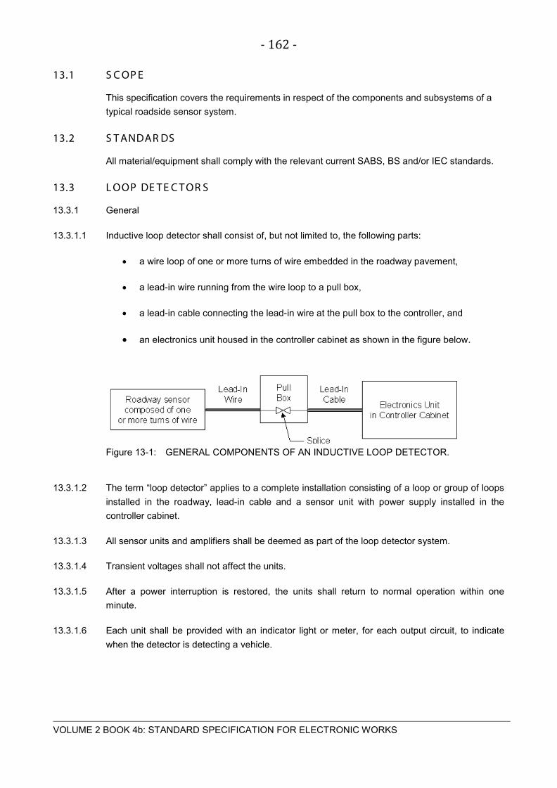
- 162 -
VOLUME 2 BOOK 4b: STANDARD SPECIFICATION FOR ELECTRONIC WORKS
13.1 S C OP E
This specification covers the requirements in respect of the components and subsystems of a
typical roadside sensor system.
13.2 S T ANDAR DS
All material/equipment shall comply with the relevant current SABS, BS and/or IEC standards.
13.3 L OOP DE T E C T OR S
13.3.1 General
13.3.1.1 Inductive loop detector shall consist of, but not limited to, the following parts:
• a wire loop of one or more turns of wire embedded in the roadway pavement,
• a lead-in wire running from the wire loop to a pull box,
• a lead-in cable connecting the lead-in wire at the pull box to the controller, and
• an electronics unit housed in the controller cabinet as shown in the figure below.
Figure 13-1: GENERAL COMPONENTS OF AN INDUCTIVE LOOP DETECTOR.
13.3.1.2 The term “loop detector” applies to a complete installation consisting of a loop or group of loops
installed in the roadway, lead-in cable and a sensor unit with power supply installed in the
controller cabinet.
13.3.1.3 All sensor units and amplifiers shall be deemed as part of the loop detector system.
13.3.1.4 Transient voltages shall not affect the units.
13.3.1.5 After a power interruption is restored, the units shall return to normal operation within one
minute.
13.3.1.6 Each unit shall be provided with an indicator light or meter, for each output circuit, to indicate
when the detector is detecting a vehicle.

- 163 -
VOLUME 2 BOOK 4b: STANDARD SPECIFICATION FOR ELECTRONIC WORKS
13.3.1.7 Units shall be designed to provide ease of maintenance with easily accessible electronic
components.
13.3.2 Standards
NEMA TS1 and TS2 specifications
13.3.3 Electronic unit
The electronics unit, loop detector, shall meet or exceed the following design and performance specifications:
Table 13-1: LOOP DETECTOR SPECIFICATIONS
Parameter Specification
Voltage 230 VAC at 50 Hz
Voltage tolerance + 20%
Temperature range -80 °C to +40 °C
Adjustment Fully self-tuning with automatic drift compensation
Connector 11 pin Amphenol CP type
Controls
Mode,
Frequency select (3 possible)
Sensitivity and presence (3 positions)
Output type Presence, contact change over and presence selectable, contact closure pulse
Output rating 100 VA, 5 A, 230 V
Sensitivity 0.02 % (max setting)
Presence time 2 hours (max setting)
Loop inductance 50 – 2500 microhendies (µH) range
Power failure Detectors must resume operation immediately after power interruptions
Lightning
Zener diode protection for over-voltage induced on loop leads
Capacitive arc protection
Connections All connections to be weatherproofed
13.3.4 Roadway installation
A typical inductive loop installation is shown in the figure below.

- 164 -
VOLUME 2 BOOK 4b: STANDARD SPECIFICATION FOR ELECTRONIC WORKS
Figure 13-2: TYPICAL INDUCTIVE LOOP INSTALLATION.
13.3.5 Marking out
Road chalk or spray paint shall be used to mark out the loops and feeders on the roadway in
accordance to the Employers drawings. The resident Engineer shall signoff the marked
locations prior to commencement of slot cutting.
Notes:
The loops shall be parallel to the edge of the road and the leading and trailing edges shall be at
right angles to the edge of the road. Feeders are to be parallel to the loop edges.
13.3.6 Slot cutting
Slot cutting shall be carried out according to the following specifications:
a) Loop slots shall have a width of 4mm-10mm and be deep enough to provide for a
minimum of 25mm of sealant over the uppermost wire. Feeder slots must be cut to a
depth of at least 80mm and a width of 10mm.
b) The depth of each loop/ feeder shall be such that no part of any loop/feeder cable shall
have a sealant cover of less than 25mm.
c) The blade used shall be of a diamond impregnated type. This shall be kept cool with a
constant supply of water flowing over the rotating blade.

- 165 -
VOLUME 2 BOOK 4b: STANDARD SPECIFICATION FOR ELECTRONIC WORKS
d) Sawing shall be done carefully by a competent operator to prevent undue spalling of the
road surface.
e) The completed grooves shall be accurate to within a tolerance of 5 mm both horizontally
and vertically in respect of position, lengths and widths specified.
f) Slot cutting in concrete for inductive detector loops shall not be performed until after the
concrete pavement has been grounded, straight-edged and brought into tolerance.
g) All internal corners shall be rounded to eliminate sharp turns,
h) Slots shall be cleaned out with high-pressure water after cutting and then thoroughly
dried with compressed air.
i) Residue resulting from slot cutting operations shall not be permitted to flow across
shoulders or lanes occupied by public traffic and shall be removed from the pavement
surface before any such material flows off the pavement surface.
j) The Contractor shall be responsible for disposing of materials/residue from slot cutting
operations.
k) Slots shall be free of debris and water prior to loop wire installation.
13.3.7 Cable laying
Cable laying shall be done according to the following specifications:
a) Loop and feeder cable must be well insulated to withstand abrasion, insulation such as
cross-linked polyethylene or polypropylene shall be specified.
b) The wire for the loop shall be PVC insulated 2,5 mm single core stranded copper
conductor to SABS.150/70 600/1000V unjoined and untwisted
c) Each loop and feeder pair shall be one continuous wire.
d) The continuous length of wire shall be inserted in the groove in a clockwise direction
such that three complete turns will be provided for the loop. The loop and feeder wires
shall be protected by means of a neoprene cord inserted snugly into the groove.
e) The cable shall be laid in the bottom of the slot.
f) Each feeder shall be well twisted at a uniform rate of 10-15 turns per meter run.
g) The feeder pairs associated with each loop shall be identified at their free ends as soon
as twisting has been completed in order to minimize confusion.
h) The feeder wires must be contained in high impact plastic ducting if they run through a
verge or central reservation to the electronic unit housing.

- 166 -
VOLUME 2 BOOK 4b: STANDARD SPECIFICATION FOR ELECTRONIC WORKS
i) All cable joints must be soldered, insulated, and waterproofed to ensure environmental
protection and proper operation.
j) After the loops and feeders have been laid they must be tested for continuity and
insulation to earth and the results documented before reinstatement commences.
13.3.8 Additional Information
Guidance for the Number of Cable Turns for Inductive Loops
Loop Perimeter under 8 Metres: 4 Turns
Loop Perimeter 8 – 10 Metres: 3 Turns
Loop Perimeter over 10 Metres: 2 Turns
13.3.9 Reinstatement of slots
Slot reinstatement shall comply with the follow specifications:
a) Loop sealant shall be applied to insulate and protect the wires.
b) Loop sealant shall encapsulate loop wires to the fullest extent possible.
c) Loop sealant shall either be rubberized asphalt or epoxy resin.
d) Before setting, surplus sealant shall be removed from the adjacent road surfaces
without the use of solvents.
e) Minimum of 25 mm of sealant shall cover the loop wires.
f) Sealant shall adhere to asphalt or concrete, but not necessarily to both.
g) For installation in an existing roadway, loop sealant shall be poured to within 3mm of
surface.
h) For installation prior to overlay, the slot shall be filled completely with sealant before
paving.
i) After reinstatement each loop shall be tested again for continuity and insulation.
13.3.10 Loop termination
a) All installed loops shall be terminated into a roadside housing to protect the loop feeder
connection from deteriorating due to weather and damage from vandals.
b) The loop housings shall be in accordance to customer requirements.

- 167 -
VOLUME 2 BOOK 4b: STANDARD SPECIFICATION FOR ELECTRONIC WORKS
c) Loop feeders shall be terminated in the housing into a termination strip where each loop
is identified by means of a loop identifications label.
13.4 AX L E S E NS OR S
13.4.1 General
a) All axle sensor units and logic cards shall be deemed as part of the axle sensor.
b) Units shall be designed to provide ease of maintenance with easily accessible electronic
components.
13.4.2 Axle Sensor Installation
a) The axle sensor shall be tested under no-load conditions prior to installation according
to supplier specifications.
b) Installation sites for the axle sensor need to be selected carefully. The road surface ruts
shall be less than 25 mm under a 500 mm straight edge.
c) Slots for the axle sensor shall be formed in the road surface by cutting with a suitable
diamond saw to a depth and width specified by the axle sensor supplier. The slot shall
be roughened and cleaned with a wire brush on the bottom and sides for good adhesion
by the grout.
d) Slot cutting in concrete for axle sensors shall not be performed until after the concrete
pavement has been grounded, straight-edged and brought into tolerance.
e) Slots cut in the pavement shall be washed clean, blown out and thoroughly dried before
installing sensors. Residue resulting from slot cutting operations shall not be permitted
to flow across shoulders or lanes occupied by public traffic and shall be removed from
the pavement surface before any such material flows off the pavement surface.
f) The Contractor shall be responsible for disposing of materials/residue from slot cutting
operations.
g) Any excessive grout must be ground off once the sensor is installed and the grout is
cured, using an angle grinder or belt sander. The grout shall be flush with the road
surface to minimize and chance of tires bridging over the sensor.
h) Feeder wires shall be without any joints or splices up to the controller where the feeders
are terminated.
i) The transition of cables from the road to the edge of the road shall be effected by drilling
a 22 mm diameter hole 400 mm from the edge of the road and at an angle such that the
drill hole shall emerge at a depth of 500 mm below the surface at the edge of the
pavement. A 20 mm diameter low pressure polyethylene pipe shall be inserted into the
drilled hole to at least 25 mm below the surface of the road to be used as a sleeve pipe.

- 168 -
VOLUME 2 BOOK 4b: STANDARD SPECIFICATION FOR ELECTRONIC WORKS
The polyethylene pipe shall lead the feeders to a PVC U/G gully housing located at the
edge of the road.
j) All conductors shall be identified and labelled, in the junction box adjacent to the loops
and near the termination of the conductors in the controller cabinet.
13.5 WE IG H-IN-MOT ION S P E C IF IC AT IONS
13.5.1 SCOPE
This specification covers the requirements for a weigh-in-motion (WIM) system.
The scope includes the development, supply, delivery, installation, testing and commissioning of
the required software and hardware constituting a complete and fully operational WIM system
including, but not limited to the requirements as specified herein. The WIM system shall be
capable to transfer the required data to a host control/information system for further processing.
13.5.2 STANDARDS
13.5.2.1 National and International Standards, Publications and Codes
The latest edition at time of tender of the following National and international Standard,
Publication and Codes shall be read in conjunction with this specification:
a) SABS IEC 60529: Degrees of protection provided by enclosures.
b) ASTM E 1318 – 02: Standard Specification for Highway Weigh-In-Motion (WIM)
systems with User Requirements and Test Methods
c) National Road Traffic Act 93 of 1996

- 169 -
VOLUME 2 BOOK 4b: STANDARD SPECIFICATION FOR ELECTRONIC WORKS
13.5.3 INTRODUCTION TO THE WIM SYSTEM
13.5.3.1 The weigh-in-motion (WIM) system offered shall be supplied by a reputable supplier, with local
after sales service.
13.5.3.2 The system shall include equipment and software for collecting, processing, storing, transmitting
and manipulating information related to the counting, classifying, speed monitoring, and the
weighing of vehicles.
13.5.3.3 The WIM system shall weigh each axle of a vehicle, and pass the weight and axle spacing
information recorded to a host controller. The host controller shall then store and analyse this
data to determine the suitability of that vehicle for weighing station bypass. The host controller
sends an authorization bypass or denial message to the subject vehicle via a traffic light
controller.
13.5.3.4 The WIM system may also function as the host controller.
13.5.4 GENERAL REQUIREMENTS AND WIM SYSTEM COMPONENTS
13.5.4.1 The WIM System shall provide for single threshold weighing, and operate over a speed range of
2 to 10 km/h. The WIM scale shall be able to measure axles up to 15 000kg. The WIM system
shall consist of two loops and one or two decks per lane, measuring the left and right side of
each axle, installed in the lane of travel. The scale decks and loops shall cover the entire lane
width. The WIM - system shall measure the following minimum parameters:
a) The speed of the vehicle
b) The volume of vehicles passing the point
c) Time of departure of each vehicle
d) Axle pattern and classification of vehicle
e) Weight per axle
f) Total weight for the vehicle.
g) Following interval (% ≤ 2sec)
h) Vehicle length
Unless specified to the contrary in the detail specification the scale decks shall operate on any
suitable and proven technology.
13.5.4.2 Sufficient data must be collected to allow, after processing thereof, for the determination of the
following information:
a) Daily traffic flows per lane;

- 170 -
VOLUME 2 BOOK 4b: STANDARD SPECIFICATION FOR ELECTRONIC WORKS
b) Hourly traffic flows per lane;
c) Split between heavy vehicles and light vehicles per day per lane;
d) Split between heavy vehicles and light vehicles per hour per lane;
e) Short heavy vehicles (up to 12,5 m long);
f) Medium heavy vehicles (up to 12,5 m and up to 17,0 m long);
g) Long heavy vehicles (over 17,0 m long);
h) The number of heavy vehicles per axle group per day where “axle group” refers to the
number of axles per heavy vehicle;
i) Vehicle classification as per the RSA axle classification scheme;
j) Individual axle loads (only for heavy vehicles);
k) Axle load violations;
l) Scale load violations;
m) Excess over the legal axle load limits of the axles exceeding the legal axle load limits;
n) Total E80 unit, determined from the formula E80 = Σ(δ/8,2)n, where n = 4,2 and δ is the
actual axle load in ton calculated on individual axles;
o) Total E80 portion resulting from the axles exceeding the legal limits;
p) Grouped distribution of heavy axles with groups 0-1 t, 1-2 t, …………, 19-20 t; and
q) Average E80 units per RSA vehicle classification.
r) Speed.
s) Following distance (% ≤ 2 sec).
The WIM controller shall be equipped with a monitor, keyboard and mouse to do programming
changes to the system.

- 171 -
VOLUME 2 BOOK 4b: STANDARD SPECIFICATION FOR ELECTRONIC WORKS
13.5.5 FUNCTIONAL REQUIREMENTS
13.5.5.1 The WIM System shall be able to accommodate vehicles and vehicle combinations with up to 9
axles and shall automatically determine for each vehicle:
a) Weight of each axle:
Accuracy:
Axle Load ±15%
Axle-Group Load ±10%
Wheel load ±20%
Gross Vehicle weight ±6%
b) Axle spacing, vehicle length and speed:
Accuracy:
Axle spacing ± 150 mm
Vehicle length ± 300 mm
Speed ± 2 km/h
NOTE: All accuracy performance testing will be based on at least 40 truck
measurements.
c) Vehicle Classification:
The WIM System shall provide for a minimum of 19 vehicle classifications. Class 1
through Class 17 shall be used according to the RSA classification Scheme. Class 18
will identify special vehicles as determined by the user. Class 19 will identify any
vehicle that does not conform to the classification criteria for Classes 1 through 18.
Classification criteria for Classes 1 through 19 shall be fully programmable by the user.
The WIM System shall provide sufficient flexibility in programming parameters including
number of axles, axle spacing, and weights (gross, or axle and gross) for each of these
classes so that accurate classifying is achievable.
d) Determination of Weight Violations:
For any vehicle meeting the front axle weight threshold (discussed below), the WIM
System shall determine which, if any, axle(s) or axle grouping(s) exceed the weight
limits set forth in Table 1: Violation Rules. Any vehicle with one or more violations will
be coded as to such a violation or combination of violations. The weight limitations set
forth in Table 1: Violation Rules shall be the default settings. Such weights shall be
programmable by the user.

- 172 -
VOLUME 2 BOOK 4b: STANDARD SPECIFICATION FOR ELECTRONIC WORKS
Table 13.5-1: VIOLATION RULES
Item No.
Description High Value Unit Comments
National Road Traffic Act 93 of 1996
1 Speed > 10 km/h
2 Gross Vehicle Mass > 56 000 kg GVM Reg 240
3 Single Wheel Load > 3 850 kg Reg 240
4 Single axle with two wheels (steering) > 7 700 kg Reg 240
5 Single axle with two wheels (non-steering) > 8 000 kg Reg 240
6 Single axle with four wheels > 9 000 kg Reg 240
7 Tandem axle with unit with two wheels per axle > 16 000 kg Reg 240
8 Tandem axle with unit with four wheels per axle > 18 000 kg Reg 240
9 Tridem axle unit > 24 000 kg Reg 240
10 Bridge Formula (P = 2 100 L + 18 000) > P kg
Concentration of axle loads over any given distance P = Load in kg, L = Distance in metres between extreme axles of any group of axles Reg 241
11 Gross Combination mass > 56 000 kg GCM
12 Unbalance between left and right > 10 %
Reg 242 (a) (i+ii)
13 Following distance < 3 Sec
14
Ratio between steering and all other axles (combination vehicles) < 11 % Reg 242 (b)
15
Ratio between steering and all other axles (not combination vehicles) < 30 % Reg 242 (c)
16
Ratio between steering axle and other axles (normal vehicles) < 20 % Reg 242 (d)
17 Ratio between steering axle and other axles (tractor) < 12 % Reg 242 (d)
13.5.5.2 The controller unit of the WIM System shall calculate and temporarily store all specified data on
a storage medium. The on-site data storage device shall have the capacity to store a minimum
of 30 days of vehicle count data in addition to a minimum of 30,000 individual vehicle records.

- 173 -
VOLUME 2 BOOK 4b: STANDARD SPECIFICATION FOR ELECTRONIC WORKS
The storage device shall be a type that is not susceptible to loss of accumulated data should
electrical power be interrupted. The controller unit shall continue to calculate and store data for
all vehicles passing through the system during periods of access, both on-site by portable PC
and remotely by the host computer for purposes of programming, real-time view, and
downloading of data.
The controller unit shall store the following data:
a) Hourly vehicle counts by class and by speed range for each 24-hour period
(Class/Count summary) as per SANRA type 21 and type 30 data records.
b) Individual vehicle records for all vehicles with a front axle weight greater than 1 500 kg
(hereafter referred to as "truck records"). The front axle weight threshold for truck
records shall be programmable by the operator with default setting of 1 500 kg. Each
truck record shall include, as a minimum, the following data:
1. Time and date
2. Lane number
3. Vehicle number
4. Speed
5. Vehicle classification and axle pattern
6. Weight in kilogram (kg) of each wheel or dual set of wheels by left and right side
and by axle number
7. Weight per axle by axle number
8. Total weight for the vehicle
9. Spacing in millimeters (mm) between each sequentially numbered axle
10. Overall length of each vehicle or combination of vehicles in millimeters (mm)
11. Code for weight violation(s)
12. Code for invalid measurement(s)
13. Following interval

- 174 -
VOLUME 2 BOOK 4b: STANDARD SPECIFICATION FOR ELECTRONIC WORKS
13.5.5.3 Transmitting of each truck record to the host computer shall be executed as soon as the truck
record is completed. If communication is lost with the host computer, the truck record shall be
stored as specified. All truck records in the storing medium of the controller shall be transmitted
to the host computer when communication to the host computer is back on-line.
13.5.5.4 Data shall be calculated and formatted such that all data can be accessed and all required
reports can be generated by use of software running on the host computer. This data shall as
per SANRAL data format.
13.5.5.5 All equipment shall operate properly within an atmospheric temperature range of -10°C and
+50°C.
13.5.5.6 The controller unit's communication capabilities shall be fully compatible with the host computer.
13.5.6 CONCRETE REMOVAL (WIM SCALE FRAME)
13.5.6.1 Neither saw cutting nor the removal of concrete for the WIM scale frames shall be performed
until after the concrete pavement has been grounded, straight-edged and brought into tolerance.
13.5.6.2 The outlines of excavations in the pavement for the WIM scale frames shall be cut on a neat line
to minimum depth of 50 mm with a power-driven concrete saw before any material is removed.
Residue resulting from cutting operations shall not be permitted to flow across shoulders or
lanes occupied by public traffic. Residue shall be removed from the pavement surface before
any such material flows off said surface, and shall be disposed of.
13.5.6.3 The installation of the WIM frames and sensors shall comply with the manufacturer
specification. The Contractor shall submit the detail installation procedure for approval to the
Employer 30 days before the start of the installation.
13.5.7 EQUIPMENT ENCLOSURE
13.5.7.1 Requirements for Housing of Equipment
A suitable enclosure assembly for housing all required WIM system electronic equipment,
controller electronic equipment and instrumentation shall be supplied and installed.
13.5.7.2 Design and Construction
a) The enclosure shall be a freestanding unit with bottom cable entry and shall be suitable
for outdoor installation.
b) The degree of protection shall be at least IP55 to SABS IEC 60259.
c) The cabinet shall be of sufficient size to accommodate all equipment.
d) Special care shall be taken for the design of the cooling system of the enclosure, to
ensure that the internals of the enclosure are continually maintained under pressure and

- 175 -
VOLUME 2 BOOK 4b: STANDARD SPECIFICATION FOR ELECTRONIC WORKS
that the internal temperature is maintained at a supplier specified operating level for all
components.
e) The cabinet and doors shall be manufactured to be bulletproof when shot at with a 9
mm pistol at a distance of 3 meters. All exterior seems shall be continuously welded. All
surfaces shall be free from weld flash. Welds shall be smooth, neatly formed, free from
cracks, blowholes and other irregularities. All sharp edges shall be ground smooth.
f) The cabinet shall be vermin proof.
g) The cabinet shall have a single front door equipped with a lock. When the door is closed
and latched, the door shall be locked. The handle shall have provision for padlocking in
the closed position.
h) The cabinet doorframe shall be designed so that the latching mechanism will hold
tension on and form a firm seal between door gasketing and doorframe.
i) The main door shall close against a weatherproof and dust proof, closed-cell neoprene
gasket seal. The gasket material shall be a minimum of 6 mm thick by 12 mm wide. The
gaskets shall be permanently bonded to the cabinet.
j) Two keys shall be furnished for the cabinet.
k) All doors shall be provided with catches to hold the door open at both 90° and 180°.
l) Door hinges, pins and bolts shall be made of stainless steel. The hinges shall be bolted
to the cabinet. Hinge pins and bolts shall not be accessible when the door is closed.
m) The cabinet shall be provided with substantial metal shelves and brackets to support
equipment.
n) No screws, bolts or nuts shall protrude beyond the outside wall of the cabinet.
o) The colour of the cabinet shall be as follows:
i. EXTERIOR - White as per SABS 1091 (textured finish)
ii. INTERIOR - White as per SABS 1091 with white equipment mounting
chassis plates.
p) All coatings shall be smooth, free of flow lines, paint washout, streaks, blisters and other
defects that would impair serviceability or detract from general appearance.
13.5.7.3 Terminals, Wiring and Facilities
a) Conductor sizes and types shall be selected according to their application.

- 176 -
VOLUME 2 BOOK 4b: STANDARD SPECIFICATION FOR ELECTRONIC WORKS
b) Conductor colours shall be selected to suit their application and purpose, provided that
all conductors on neutral potential shall be black and all earth conductors shall be
green, green and yellow, or bare copper conductors.
c) All conductors shall be provided with suitable wiring numbers on both ends, which
numbers shall also be clearly marked on the wiring diagrams. Where conductors are
connected to terminal blocks, the terminals shall be clearly numbered and shall be
clearly identifiable on the loop diagrams and schematic diagrams.
d) Wiring within the controller cabinet shall be neatly arranged and laced, or enclosed in
plastic tubing or raceway. All cabinet wiring shall be continuous from its point of origin to
its termination point. Splices are not acceptable. All cables shall be provided with strain
relief.
e) Mechanical clamps shall secure all connecting cables and wire-runs. Stick-on type
clamps are not acceptable.
f) Conductor passages through any sharp object shall be finished with purpose-made
rubber or plastic linings to prevent damage to the conductor insulation.
g) Conductors used in cabinet wiring shall terminate with properly sized captive type
terminals.
h) An equipment grounding conductor bus shall be provided in the cabinet. The bus shall
be grounded to the cabinet and shall be connected to the ground conductor of the
power supply.
i) All doors shall be bonded to the earth bar in the cabinet by means of braided copper
conductors (16 mm² minimum), screw down lugs and brass screws.
j) Suitably sized terminal blocks, with a minimum rating of 10 amperes, shall be provided
for field connections. Field terminals shall be installed within 300 mm of the face of the
cabinet and shall be oriented for screwdriver operation from the door opening. All
terminals shall be a minimum of 300 mm above the foundation.
k) Permanent alphanumeric labels shall identify all field input/output (I/O) terminals.
l) A socket outlet of 15A rating complete with local earth leakage shall be mounted in a
readily accessible location inside the cabinet.
m) The cabinet shall be provided with a fluorescent lighting fixture mounted on the inside
top of the cabinet near the front edge for sufficient illumination. A door-actuated switch
shall turn the light on when the door is open, and off when the door is closed
n) An incoming power supply surge arrester shall be provided. The surge arrester shall
provide for surge protection between live and neutral and between live, neutral and
earth.

- 177 -
VOLUME 2 BOOK 4b: STANDARD SPECIFICATION FOR ELECTRONIC WORKS
o) All sensor cabling shall be installed in galvanized conduit at least 600 mm deep. All
conduits, pull boxes, etc. shall be bonded together and earthed. Marking tape shall be
inserted ± 250 mm below ground level during backfilling of trenches.
13.5.7.4 Power Panel
a) The power panel shall consist of a separate, wholly enclosed module, securely
fastened.
b) The power panel shall be wired to provide the necessary power to the cabinet and all
equipment and auxiliary equipment.
c) It shall be manufactured from sheet steel with a removable plastic front cover.
d) The panel shall be of such design so as to allow access to the main and auxiliary circuit
breakers without removing the front cover.
e) The power panel shall house the following components:
i. Line surges voltage protection unit.
ii. Main circuit breaker (40A) complete with earth leakage unit.
iii. Two (2) auxiliary 20 A circuit breakers. One for supplying the WIM equipment
with electrical power and the other wired to the required socket outlet unit
located in the cabinet.
iv. A 10-amp auxiliary circuit breaker. This breaker shall supply power to the light
mounted in the cabinet.
13.5.7.5 Installation
a) The cabinet shall be located next to the roadway, as close as practical to the sensors
but safely out of the way of traffic. The final position shall be to the approval of the
Employer.
b) The contractor shall construct a concrete foundation (extending at least 150 mm above
final ground level) for the controller cabinet and install the controller cabinet on said
foundation.
c) The cabinet shall be supplied with at least four (4) anchor bolts to properly secure the
cabinet to its base. The cabinet flange for securing the anchor bolts shall not protrude
outward from the bottom of the cabinet.
d) An adequate amount of conduit shall be provided through the concrete foundation for
wiring and cabling purposes.
e) The cabinet shall not be erected until the foundation has set at least 7 days.

- 178 -
VOLUME 2 BOOK 4b: STANDARD SPECIFICATION FOR ELECTRONIC WORKS
f) All foundations shall be plumb and square.
g) A pliable seal, composed of caulking compound, mastic or similar, shall be placed
between the controller cabinet and the concrete foundation for an effective seal to
prevent water, dust, dirt and insects from entering the cabinet.
13.5.8 CALIBRATION
The purpose of calibration is to detect and eliminate systematic errors of measurement. The
axle weighing equipment must be calibrated and certified as sufficiently accurate once every
three months, using a minimum of 100 heavy axles per direction, as found on trucks selected at
random from the traffic stream. The calibration procedure shall consist of the following steps:
a) Use the observed (o) and true (t) mass of the first 100 axles whose true load t exceeds
5 t.
b) For each above pair calculate the ratio r = o/t.
c) Calculate the average (ra) and the standard deviation (rs) of the 100 values for r. Using
these, calculate the coefficient of variation cv = rs/ra.
d) Enter Graph 1 with the cv as determined above and read off the corresponding
calibration sample size z.
e) If z < 101 no additional sampling is required. Otherwise continue sampling axles
heavier than 5 t until the z actually taken is equal or greater than the z indicated by
Graph 1 when entered with the cv calculated from the z observations.
f) Calculate the ra, rs and cv of the final sample. Use ra to adjust the equipment
sensitivity. Append the record of all measurements to the calibration protocol.
The above procedure is preliminary and subject to amendments in the course of the Contract.
13.5.9 ACCEPTANCE TEST
The Contractor shall demonstrate that the High Speed WIM System is available for use by the
Employer by successfully completing the acceptance test for each lane of data collection.
The acceptance test shall consist of the following:
a) Continuous operation of the WIM System on-site equipment for 72 consecutive hours.
Failure of the system to record, store and make available data meeting the
requirements set forth in this specification for an accumulated time exceeding 3 hours
during the 72 hour period shall be cause for the acceptance test to be repeated.
Unavailability shall be the failure of the system to pass the acceptance test

- 179 -
VOLUME 2 BOOK 4b: STANDARD SPECIFICATION FOR ELECTRONIC WORKS
13.5.10 MAINTENANCE AND OPERATION MANUALS
The Contractor shall furnish a maintenance manual for the controller unit, including vehicle
detector sensor units, and an operation manual for the system. The maintenance manual and
operation manual may be combined into one manual. The manual(s) shall include, but need not
be limited to, the following items:
a) Specifications
b) Design characteristics
c) General operation theory
d) Function of all controls
e) Trouble shooting procedure (diagnostic routine)
f) Block circuit diagram
g) Geographical layout of components
h) Schematic diagrams
i) List of component parts with stock numbers
j) Documentation for application software
k) Preventative maintenance schedules
13.5.11 WARRANTY
All equipment including the WIM sensors, lead-in cables, frames and mounting hardware
provided shall include the manufacturers or suppliers warranty and shall not be less than 12
months.
Such warranty periods shall begin upon completion of the acceptance test of the weigh-in-
motion system and shall include all parts and all installation costs, including traffic control if
necessary, to make the repairs.

- 180 -
VOLUME 2 BOOK 4b: STANDARD SPECIFICATION FOR ELECTRONIC WORKS
S E C T ION 14 R OADS IDE DIS P L AY S Y S T E M

- 181 -
VOLUME 2 BOOK 4b: STANDARD SPECIFICATION FOR ELECTRONIC WORKS
14.1 S C OP E
The section describes the detail specifications related to roadside display systems. Roadside
display systems are defined as any visual medium, variable or fixed used to communicate
information to road users.
14.2 S T ANDAR DS
All material/equipment shall comply with the relevant current SABS, BS and/or IEC standards
14.3 T R AF F IC L IG HT S
This section provides specifications to be followed for the installation of all permanent traffic
signals and associated equipment. Specifications are also given for the installation of temporary
traffic signals.
14.3.1.1 Work safety during installation
Installation work shall be carried out with minimum disruption to pedestrian and vehicular traffic.
Measures shall be taken to ensure the safety of the contractor's staff and the public during the
installation process. Adequate working space, warning signs, means of access and lighting
shall be provided.
The contractor shall be responsible for the placing of signs and barriers and associated traffic
management during the installation period.
Working conditions shall be in accordance with the South African Health and Safety Act.
14.3.1.2 Responsibilities
The contractor shall be responsible for the following:
a) The contractor will be responsible for managing the activities involved in the execution
of works. This will involve co-ordination with other bodies such as statutory undertakers,
Police, other emergency services, and other relevant transportation authorities.
b) The contractor will be responsible for liaising with statutory undertakers and the
transportation authorities to ascertain the positions of all underground services which
may be affected by the proposed installation of traffic signals. The contractor shall also
be responsible for giving information to statutory undertakers that traffic signals are
about to be installed.
c) The contractor will be responsible for arranging a suitable (dedicated) electricity supply
to the proposed installation and for indicating the exact location at which such a supply
is required.
d) The contractor will be responsible for arranging the communications interface for UTC
(Urban Traffic Control) and remote monitoring connection, where specified.

- 182 -
VOLUME 2 BOOK 4b: STANDARD SPECIFICATION FOR ELECTRONIC WORKS
e) The contractor will have overall responsibility for ensuring that the proposed installation
complies with all relevant statutory requirements.
14.3.1.3 Preparation
A detailed plan (as built) of the layout of the site and signal installation shall be produced prior to
commencement of the works.
The detailed plan shall contain the following:
a) The plan shall include all cabling and ducting details, duct chambers, pole-pits, detector
sitting together with loop configurations and spacing details between the loops.
b) The plan shall also indicate existing inspection covers (where applicable), trees, lighting
columns, signs and gantries. Location details of previously installed services (gas,
electricity, telephone, water etc) shall be indicated on the plan (Site investigation and
survey may be required).
c) The plan detailing the signal equipment shall be at 1:200 scale. An additional 1:500
scale drawing showing linking details and the positions of sensors or other loops shall
also be provided.
The plan shall be made available to the Employer in AutoCAD, PDF and hardcopy format.
14.3.2 Civil Engineering works
14.3.2.1 General
For the purposes of this section civil engineering works include the following:
a) all excavations and trenching both on and off the roadway
b) all duct laying, including bedding material, cable draw cords and draw pit construction
c) all back filling and reinstatement of excavations and trenches
d) removal of all surplus soil, stones, etc. from the site and making sure that the contractor
has a valid license for the disposal of spoil
e) the setting out, provision and levelling of all foundations ready to receive the equipment
when it is installed
f) the provision of signs and barriers for both pedestrian and vehicular traffic
14.3.2.2 Ducting
The installation of electrical cabling shall be fully ducted and provided with draw pits and pole
pits/adaptors so that any cable can be installed or removed with minimum civil engineering
works.

- 183 -
VOLUME 2 BOOK 4b: STANDARD SPECIFICATION FOR ELECTRONIC WORKS
The following specifications shall be adhered to:
a) All duct tranches shall be excavated to a minimum depth of 800mm.
b) Ducts shall be enclosed (top and bottom) in course carvel to a depth of 200mm.
c) Draw pits shall be provided at the end of each duct run and where the duct changes
direction, drawn bends shall not be incorporated in the duct runs except by the prior
written approval of the Employer. The layout shall be such that the tactile paving area is
kept free of inspection chambers.
d) Traffic signal equipment, the ducts and cables shall be coloured orange and marked
'Traffic Signals' along the length.
e) The contractor shall ensure that all necessary measures are taken as required by any
Statutory Undertaker and/or Authority for the protection of its mains, pipes, cables or
other apparatus during the progress of the works and also to construct and provide as
required any auxiliary works necessary for the prevention of damage and interruption to
Statutory Undertakers and/or Authority services to their satisfaction.
14.3.2.3 Electrical installation
This section shall be read in conjunction with Volume 2 book 3, Standard Specification for
Operations and Maintenance Electrical, Mechanical and Electronic equipment document,
section A: Electrical equipment and design
14.3.2.4 Supply
In addition to the standard specifications listed in Volume 2 book 3, the following additional
requirements shall be adhered to:
a) The supply cable shall be terminated within the controller or in a separate power supply
termination pillar so that the system can be totally isolated from the supply.
b) All exposed conductive parts of the installation shall be connected to an earth electrode
which is electrically independent of the source earth.
c) The cables to be installed between the controller and the pole top terminal box, as well
as between individual terminal boxes shall be 600/1000 volt, PVC insulated, PVC
sheathed, steel wire armoured, PVC sheathed to SANS 1574 and 1507.
d) The cables shall be multicore cables with 1,5 mm², copper conductors. The number of
cores shall be as specified in the detail specification and shall be either 7, 19, 24 or a
combination thereof.
e) No cable joints shall be permitted. The contractor shall allow at least one meter cable
slack in each pole to reduce the possibility of cable breakage in the event of a collision.

- 184 -
VOLUME 2 BOOK 4b: STANDARD SPECIFICATION FOR ELECTRONIC WORKS
14.3.2.5 Earthing
In addition to the standard specifications listed in Volume 2 book 3, the following specifications
regarding earthing shall be adhered to:
a) A 1,8 copper earth spike shall be installed in the ground beneath the controller, from
which the controller and each pole shall be earthed using 16 mm stranded base copper
earth conductor
b) All cabinets, poles and other metal hardware comprising the traffic signaling equipment
installation shall be connected to the installation earthing point by a protective
conductor. Extraneous conductive parts such as guardrails shall not be connected.
c) The connection to metalwork shall be made internally to a secure standing terminal on a
part of the enclosure which cannot be removed for routine maintenance. All auxiliary
connections (eg. doors, etc.) shall be made to the secure terminal. All connections shall
be both electrically and mechanically sound.
d) Wire terminations may be soldered, crimped or screwed. If the latter is used then a type
where the screw does not make direct contact with the conductor shall be used (eg.
spring leaf type)
e) Individual protective conductors shall be insulated and colour-coded green with a yellow
stripe. Sheathed and/or armoured cables within traffic signal poles and/or equipment
shall have the cable sheaths and/or armouring connected to earth using a method of
earthing which provides sound mechanical and electrical integrity.
f) Where the sheathed and armoured cables are installed vertically in traffic signal poles,
support clips shall be used where possible.
g) The installation earthing point shall be connected to the main earthing terminal(s) by a
copper protective conductor, insulated and colour coded green/yellow stripe. For
mechanical strength and resistance to damage, the conductor shall have a minimum
cross sectional area of 6mm2.
h) The electricity supply provided shall be single phase and shall be terminated in a circuit
breaker of a type having incoming phase and neutral terminals. A certified competent
person shall connect the controller conductors to the circuit breaker. The conductor
size shall not be less than 6mm2.
i) An earth terminal shall be provided.
14.3.3 Traffic signal heads
14.3.3.1 Signal heads shall be robustly constructed and fully weatherproofed. Signal heads shall be
constructed from aluminium with a high silicon content, which shall not distort or corrode after
prolonged outdoor exposure. The signal heads shall be chemically etched and coated with

- 185 -
VOLUME 2 BOOK 4b: STANDARD SPECIFICATION FOR ELECTRONIC WORKS
black enamel paint. The optical units shall be completely interchangeable and shall be easily
accessible for maintenance and cleaning. All hinges and catches shall be of stainless steel.
14.3.3.2 Each signal head shall be provided with an anodised aluminium reflector. The reflector shall be
rigidly mounted to prevent distortion of the light distribution.
14.3.3.3 A Lamp holder for traffic aspects shall be designed to accommodate type H3 10V 50 Watt or
type H2 12V 55 Watt halogen lamps. All pedestrian aspects shall be fitted with standard 70
Watt, screw type incandescent lamps. Lamps shall be replaceable without using tools.
Lampholders shall be of a metal construction to act as a heat sink. Double wound 55 VA
continuous rating, transformers shall be used for the halogen lamps. The transformer's primary
voltage shall be 220/240 volt and the secondary voltage shall be 10 Volt.
14.3.3.4 OR
14.3.3.5 The lamps of the signal heads must be of the LED cluster type (extra high brightness). The
following specifications will be preferred (deviations must get approval from the Resident
Engineer). All LED Traffic Signal Heads must comply with the SABS 1459:2004 standard
specifications. On axis luminous intensity aspects should be 380 candela minimum. Supply
Voltage should be either 10 Volt AC or 230 Volt AC with a minimum power consumption of
6Watt when not-dimmed and a maximum power consumption of 9 Watt when not-dimmed. Total
harmonic distortion (230 Volt) must be less than 12%. Lampholders shall be of a metal
construction to act as a heat sink.
14.3.3.6 Lenses shall be constructed of polycarbonate and shall have a diameter of 200 mm. The
chromaticity is to be embodied in the body of the lens itself, and shall not be externally applied.
The colour and lens description shall be specified in the detail specification and indicated on the
detail drawing.
14.3.3.7 An easily detachable black aluminium anti-phantom cross shall be fitted to each signal head.
14.3.3.8 A suitable polythene visor shall be provided on each signal head to adequately prevent the
driver of the vehicle seeing illuminated signals other than those concerning him at an
intersection. The top of the visor shall project 160 mm from the signal face.
14.3.3.9 The cable entry shall be from the underside of the upper signal head by means of flexible 20
mm PVC tubing, 610 mm in length, housing colour coded conductors protruding at least 200
mm out of the tube.
14.3.3.10 Signal heads shall be mounted onto the pole using universal pole mounting straps
14.3.4 Traffic signal back boards
14.3.4.1 Backboards shall be sufficiently robust to withstand the effects of vandalism, exposure to the
elements and wind loads. In the absence of more detailed information, the wind design load for
back boards shall be 0,75 kN/m for signal heads mounted on the standard 3,3 m poles and 1,25

- 186 -
VOLUME 2 BOOK 4b: STANDARD SPECIFICATION FOR ELECTRONIC WORKS
kN/m for signal heads mounted on the standard 5 m cantilever poles. Backboards shall be
constructed of die-cast aluminium (LM6).
14.3.4.2 Traffic signals shall be fitted with black backing boards to enhance conspicuity against
distracting backgrounds. The minimum dimension of backboards for 3 aspect signal heads shall
be 1000 mm in length and 500 m in width. The backboards shall fit directly onto the signal
heads without the use of brackets. Modular design backboards to fit signal heads with any
number of aspects shall be preferred. The backing board shall have a white border between
45mm and 55mm wide. With prior written approval from the Employer, backing boards may be
omitted in urban areas at sites where speeds are low and there are no distracting backgrounds
or where there is restricted space to achieve the adequate clearance.
14.3.4.3 The back boards shall be chemically etched and coated with black enamel paint and shall have
a 25 mm wide golden yellow border around the periphery.
14.3.5 Installation of signal equipment
14.3.5.1 General
The following general specifications for the installation of signal equipment shall be adhered to:
a) All signal heads and pedestrian push-button units (where applicable) which are not in
use should be bagged over or clearly marked as signals out of use when they are
installed to avoid confusion to pedestrian and vehicular traffic. Bags should be
sufficiently opaque so that signal aspects do not show through when lit.
b) Photocells shall be fitted to dim traffic signals at night where specified. The photocells
shall be sited and installed in accordance with the manufacturer's recommendations.
Care shall be taken to ensure that the photocell is not overshadowed, causing the
lamps to be permanently dimmed, or installed near street lighting, causing the lamps to
operate on full brightness during the hours of darkness.
c) Pedestrian push button boxes associated with pedestrian signals shall be installed so
that the indicator panel is at 90° to the roadway on the crossing side of the pole. Where
nearside signals are required, other mounting angles shall be specified. The centre of
the push button shall be between 1.0m - 1.1m above the footway level. All fixings shall
be concealed so far as possible to minimise the risk of vandalism.
14.3.5.2 Signal poles
In addition to the standard specifications listed in Volume 2 book 3, the following specifications
shall be adhered to.
14.3.5.2.1 Standard 3,3 m pole
Poles shall be of mild steel with an outside diameter of 115 mm and a mounting height of 3,3 m.
The poles shall be equipped with a base plate for mounting onto a suitable foundation frame. A
steel foundation frame complete with anchor bolts, nuts and washers shall be provided for each

- 187 -
VOLUME 2 BOOK 4b: STANDARD SPECIFICATION FOR ELECTRONIC WORKS
pole. The foundation frame shall be cast in a 20 MPa concrete foundation. A 75 mm PVC
sleeve shall be cast into the concrete foundation to provide cable access to the inside of the
pole. The base of the pole shall be designed to fracture on impact without damaging the
foundation frame.
14.3.5.2.2 Standard 5 m cantilever pole
The pole shall be designed to support a 5 m cantilever arm. A mounting lug shall be provided at
the end of the cantilever arm for attaching the signal head module. The assembled structure
shall be designed to safely support traffic signal heads and backboards having a total mass of
50 kg and a projected wind area of 1,3 m². The minimum clearance height of the cantilever arm
shall not be less than 5,1 m, measured at a point one metre from the centre of the upright pole.
The pole and cantilever shall be supplied in two sections with neither section exceeding 6 m in
length. A steel foundation frame, complete with anchor bolts, nuts and washers shall be
provided for each pole. The foundation frame shall be cast in a 20 MPa concrete foundation. A
75 mm PVC sleeve shall be cast into the foundation to provide cable access to the inside of the
pole. The base of the pole shall not be designed to fracture on impact.
14.3.6 Pole Top Terminal Box
a) Cable terminating boxes shall be provided for each pole. The terminal boxes shall be
suitable for traffic signal poles with a 115 mm outside diameter. The box shall be
constructed of aluminium and shall be fully weatherproof. The cover of the box shall be
held in position with a quick release mechanism. Provision shall be made to earth the
terminal box to the pole.
A minimum of 2 x 20 mm diameter knock-outs shall be provided in the base of the
terminal box for the flexible PVC tube to each signal head. The base shall also have
provision within the circumference of the pole to provide cable entry for at least
2 x 24 core 2,5 mm² traffic signal cables and 2 x 2 core 2,5 mm² pedestrian pushbutton
cables. Each terminal box shall be equipped with two, six-way terminal strips rated at
30 A to facilitate the paralleling of all cores of the traffic signal cable.
14.3.7 Foundations
The type and size of foundations for permanent traffic signs and signals shall be as described
in, and unless otherwise stated therein shall comply with, this specification:
a) All excavations for foundations shall be carried out in compliance with Clause 604 and
shall be cleared of all loose material before placing of concrete and backfilling.
b) Unless otherwise described traffic signs and signals supported by a single post placed
in the ground shall have the post installed centrally in 300 mm diameter or square holes
filled in with ST2 mix concrete to within 150 mm of the ground surface.

- 188 -
VOLUME 2 BOOK 4b: STANDARD SPECIFICATION FOR ELECTRONIC WORKS
c) Unless otherwise specified, posts shall be supported for a minimum of 3 days after
placing the concrete and backfilling shall not take place until at least 48 hours after
placing.
d) For traffic signals and illuminated signs provision shall be made for cable entry through
the foundation by means of ducting
e) Where pockets are formed in concrete foundations their plan dimensions shall be
sufficiently larger than those of the post to allow for positioning and bedding of the post
and backfilling of the pocket.
f) Reinstatement of existing surfaces above foundations shall be done to the Employers
satisfaction
14.3.8 General
The signal heads shall not be fitted until the concrete base has hardened sufficiently. Care shall
be taken to avoid damage to the pole during transportation and installation. Cable apertures for
signal heads, push button wiring and cable entry shall be correctly aligned. Where signal poles
are erected on a verge of unmade ground, consideration shall be given to providing a concrete
pad or paving slab(s) around the poles to provide a suitable base for a ladder for maintenance
purposes.
Where signal head assemblies are to be pole or wall mounted a horizontal clearance of not less
than 450mm from vertically above the kerb edge to the nearest part of the assembly shall be
maintained. This is to minimise the likelihood of damage to the signal heads from passing
vehicles, especially vehicles with long overhanging mirrors or loads. Where the road has a steep
camber, the clearance may be increased to 600mm. Offset traffic signal head mounting brackets
(or cranked poles may be required to ensure that the horizontal clearance is maintained.
The height to the centre of the amber optical assembly shall be between 2.4m and 4.0m for pole
mounted signals and 6.1m to 9m for over roadway signals.
Consideration shall be given to the possibility of the later addition of regulatory signs, etc. below
the existing traffic signal assembly. In this case, and within the limits of the amber signal height,
a minimum clearance of 2.1m between the lower edge of the signal assembly (including any
additional box sign or support brackets) and the footway should be maintained. It should be
noted that increased clearance (2.3m) is needed for three aspect cycle signals and it is
recommended wherever cyclists may be present. The pedestrian light signal should be erected
with a clearance of 2.1 to 2.6 metres to the lower edge of the assembly.
14.3.9 Signal controller
The controller cabinet is to be installed at the place indicated on the site plan. It shall be located
such that when the access doors are in the open position they cause minimal obstruction of the
footway (where applicable). It shall be possible to open the access doors fully and consideration
must be given to the safety of operatives during maintenance operations. If it is necessary to

- 189 -
VOLUME 2 BOOK 4b: STANDARD SPECIFICATION FOR ELECTRONIC WORKS
site the controller adjacent to the kerb then it shall not be possible for the access doors to be
opened over the carriageway and the controller shall be sited at least 0.5m from the kerb edge.
The controller cabinet shall be positioned so that it does not obstruct the view of pedestrians
waiting at the crossing or motorists on their approach. This will generally mean sitting it at the
leaving rather than the approaching side of the crossing. Consideration shall be given to placing
the controller cabinets so the traffic engineer can view the operation of the signals whilst
standing at the front of the controller.
The controller shall be installed as indicated or on a cabinet type foundation or as otherwise
specified by the Employer:
a) The cabinet shall be mounted on a case root base, locating it on one or more paving
slabs which are themselves securely bedded and properly levelled at the appropriate
depth.
b) A bed of concrete is to be laid over the base of the root and paving slab(s). The top of
the bed when finished should be 1/3 of the way up the legs of the stool and the site of
the bed smoothed.
c) That part of the excavation within the controller case root should be back filled with
compacted dry fine sand or pea gravel and topped with dry fine sand after the cables
have been terminated. The remainder of the excavation around the controller is to be
backfilled with cement bound material category 3 to ground level and the surrounding
area reinstated.
d) A layer of epoxy resin 6mm thick or as specified is to be laid on top of the sand to
prevent ingress of gas and moisture into the controller through the root and to provide a
seal with the controller case.
e) When a controller is mounted on a verge of unmade ground a concrete pad, which may
consist of paving slabs, shall be laid around the controller to a minimum width of not
less than 1 meter on those sides to which access to the equipment is required.
f) Pole-mounted controllers are to be mounted on poles correctly aligned in vertical
positions. The excavation is to be adequate to allow the pole to be planted to the depth
recommended by the manufacturer. The bottom of the hole around the pole is to be
filled with at least 300mm of concrete to the bottom of the cable entry slot. When cable
laying and testing is complete the remainder of the backfilling shall be completed, the
cable entry to the controller shall be effectively sealed against ingress of moisture into
the unit.
g) Once the electronic modules are installed in the controller, the door seals and locks
shall be checked and the controller base sealed as soon as possible to stop any water
ingress getting into the modules.

- 190 -
VOLUME 2 BOOK 4b: STANDARD SPECIFICATION FOR ELECTRONIC WORKS
h) When all the cables have been installed all duct entries into the draw pits shall be
cleaned and sealed using an approved foam sealer or mechanical duct/cable plug to
stop the ingress of dirt and silt and to prevent gas filling the duct system.
14.3.10 Signal head alignment and visibility
The following specifications shall be adhered to
a) The signal head assembly shall be suitable for the type of mounting specified. The
signal head, fixing brackets and necessary parts shall be designed so that when
installed, the signals shall be adjustable both on vertical and horizontal axis to meet the
alignment requirements of all approach roads and pedestrian crossings to which the
signals apply.
b) The signal shall be adjusted so that it does not obstruct the view of other signal optical
units within 25° of the axis of the beam. The signal head assembly shall be locked
securely after adjustment.
c) On high-speed roads, the axis of the traffic signals as defined by the manufacturer shall
be directed at a point approximately 200 m from the primary signal head and
approximately 1.5 m above ground level at the centre line of the roadway allocated to
approaching traffic.
d) Where traffic signals are mounted above the carriageway on mast arms, gantries or
suspended on catenaries, the signals shall be directed at a point approximately 1.5m
above the roadway allocated to approaching traffic between 200 m and 400 m
(depending on site conditions) from the primary signal head.
e) In other situations, the corresponding distances from the primary signal head shall be
approximately 50 m for post-mounted signals and approximately 100 m for overhead
signals. These dimensions may be varied where special circumstances require
otherwise.
f) Where signals are intended for pedestrians, cyclists and riders, the signals shall be
directed towards the centre line of the part of the carriageway allocated to pedestrian,
cycle or equestrian movement unless special circumstances require otherwise.
14.3.11 Installation of temporary signals
The following installation procedures for temporary signals shall be adhered to:
a) The contractor shall provide the relevant Authority with a drawing showing the position
of the temporary poles and signals for site approval
b) The existing pole(s) and any heads or other traffic management equipment not used
during the temporary works shall be either bagged over (or otherwise covered) or
removed from site by the contractor and carefully stored, so that on completion they
may, subject to written approval, be reinstated.

- 191 -
VOLUME 2 BOOK 4b: STANDARD SPECIFICATION FOR ELECTRONIC WORKS
c) Signals shall always be installed on the pole so that no part of the signal overhangs the
side of the drum in which they are mounted. The horizontal clearance from vertically
above the kerb edge (or the traffic barrier) to the nearest part of the assembly shall not
be less than 0.5m.
d) Wherever possible the drum position shall be marked on the ground with paint so that it
can always be replaced in the correct position if it is moved for any reason.
e) The inter-connecting cable and cable joint box shall be waterproof and protected
against accidental damage, for example by burying. Precautions shall be taken at all
times to ensure that any cable left lying above ground is positioned so that it cannot be
damaged by plant using the area or create a hazard for pedestrians, cyclists or other
road users.
f) Where temporary signals use surface laid cables, the possibility of using extra low
voltage be investigated, for example not exceeding 50V ac or 120V dc between
conductors or to earth.
g) Care shall be taken to safeguard pedestrian safety during road works within the area of
the work site and particularly at or near pedestrian crossing facilities. Temporary
pedestrian facilities may be provided on temporary signals as long as the area where
pedestrians should cross is clearly marked.
h) If the temporary signal(s) is positioned such that the normal stop line cannot be used, a
temporary stop line must be provided. The normal stop line shall be erased or covered
up with a suitable tape.
i) When the temporary installation has been completed, the contractor shall ensure that all
earthing conforms to the earthing requirements.
j) An electrical installation completion certificate for the temporary installations shall also
be produced.
14.3.12 Cables and installation of cables
Cables and the installation of cables shall comply with the following specifications:
a) Multicore intersection and linking cables shall be armoured or otherwise protected
against accidental damage. They shall be covered in an outer sheath of orange
coloured PVC. The latter need not apply to loop detector or loop feeder cables or data
transmission cables.
b) A minimum of 4 spare cores shall be provided on each cable run from the controller to
the end of the run, wherever possible or as required by the appropriate managing
authority.
c) All cables shall be of adequate size and rating to meet the electrical current carrying
requirements and electrical protection of the systems.
- 192 -
VOLUME 2 BOOK 4b: STANDARD SPECIFICATION FOR ELECTRONIC WORKS
d) A mixture of extra low and low voltages shall not be used in the same multicore cable
and in the terminations at the tops of poles etc.
e) All cables shall be laid in ducts (where applicable)
14.3.12.1 Cable termination
The following cable termination specifications shall be followed:
a) Armoured multicore cables, where the armouring forms part of the earth continuity
conductor, shall be made off using terminations fit for the purpose. Where the armour or
metal sheath of buried cables do not form part of the circuit protective conductor, they
are to be earthed.
b) Sheathed and armoured cables in vertical runs which are inaccessible and unlikely to
be disturbed shall be supported at the top of the run.
c) All earthing and cable termination or gland plates shall be constructed to resist vibration
fatigue and must have a firm and shake proof electrical and mechanical connection
between the plate and the metal work of the cabinet or pole. They must be made of
material treated, if necessary, to give corrosion resisting properties in order to maintain
electrical continuity.
d) Each cable shall be identified at each end of the cable run and intermediate runs.
Individual conductors shall also be identified. All cable runs and connections shall be
fully documented.
e) All unused cores in cables shall be identified and cut to a minimum length, long enough
to connect to the furthest making-off point within the particular unit and cut so as to be
of equal length, and shall be connected to earth at both ends; care being taken that
such spare cores are not connected prior to the earth-loop impedance test being
completed.
f) Cable joints shall not be used on new installations other than for joining inductive loop
tails to loop feeder cables. The jointing methods and materials used shall be as
specified in the contract.
14.3.13 Testing and certification
On completion of or during the installation and before commissioning, the following tests shall
be carried out by the contractor/installer:
a) Insulation resistance tests (Note: this test shall take place before connection of
the supply to the equipment.)
b) Mains connection polarity check
c) Earth loop impedance test

- 193 -
VOLUME 2 BOOK 4b: STANDARD SPECIFICATION FOR ELECTRONIC WORKS
d) Interconnecting cables shall be tested
e) Loops and loop feeder cables shall be tested
f) Checking the physical conditions of cable terminations.
An electrical installation completion certificate shall be provided by the contractor who is
responsible for the tests. Note: these certificates have to be signed by a competent person.
14.3.13.1 Performance tests
All signal functions including any Urban Traffic Control (UTC) interface (where applicable) shall
be tested on completion of the installation to ensure that the system is working as specified in
the contract. Where installed, vehicle detection and signal dimming systems are also to be
checked. It may be necessary to carry out a factory acceptance test of junction controllers to
ensure proper interpretation of the user specification.
Signal faces, including push buttons and tactile devices, which are installed and visible to road
users and pedestrians prior to switch-on shall be bagged off while such tests are in progress.
Bags shall be sufficiently opaque to ensure that the light signals are not visible to road users
during tests. During flash test (to ensure correct relationship between controller phases and site
phases) and red-lamp-monitoring test, it may be necessary to remove the bags. Care shall be
taken to ensure safety of all road users during these tests.
14.3.14 Backfill and reinstatement of roadway
The technical requirements will be specified in the contract documents.
14.3.15 Road markings and road surfacing
The contractor shall provide the necessary road markings at all installations. Care shall be taken
to maintain the integrity of any anti-skid surface treatment applied at crossing approaches.
14.3.16 Site acceptance
On completion of the installation and prior to commissioning the Employer may wish to test the
system. If testing equipment held by the Contractor is required then it shall be made available
for use by the Employer.
When the Employer is satisfied a site acceptance certificate shall be signed. Defects and/or
omissions which do not prevent the installation from functioning properly shall be recorded on
an agreed list and the certificate will then become an "interim acceptance certificate". When all
listed faults have been rectified, the "final acceptance certificate" will be signed.
14.3.17 Documentation
When the installation is complete the contractor shall supply all the documentation associated
with the scheme including at least the following:

- 194 -
VOLUME 2 BOOK 4b: STANDARD SPECIFICATION FOR ELECTRONIC WORKS
a) Controller test schedule
b) Loop test schedule
c) Earth test certificate
d) Electrical completion certificate and test results
e) 'As installed' site layout drawing
f) Controller timings sheet
g) As built cable diagrams
Note: the electrical completion certificate shall be provided before the installation is
commissioned
14.4 V AR IAB L E ME S S AG E
14.4.1 Fixed VMS signs
The VMS shall support the protocols for all existing VMS. The Contractor will be provided a
copy of the communications protocol for each VMS.
14.4.1.1 Message boards
The VMS message board supplied shall be capable of the following
a) Display all ASCII characters with character codes between 32 and 126, inclusive.
b) Left, centre, and right horizontal justification
c) Top, middle, and bottom vertical justification
d) support an NTCIP 1203 conformant interface for exchanging data
e) The sign equipment shall provide a conformation signal when the required message is
being displayed.
f) A battery backup shall be provided to ensure that in the event of a mains failure any
message displayed is retained, without corruption, and subsequent changes of not less
than 5 messages shall be possible with correct operation for not less than 24 hours.
Lanterns (where installed) will not require to be battery backed.
g) Weatherproof screen(s) are required over the front face of the sign, shall withstand,
without undue distortion, wind gusts of up to 160 km/h.

- 195 -
VOLUME 2 BOOK 4b: STANDARD SPECIFICATION FOR ELECTRONIC WORKS
h) For Defined Text Message Signs (ie. dot matrix type) the legends shall consist of
fluorescent yellow alphanumeric on a black background, or as defined in the contract
specification.
i) All printed circuit boards shall be protected against corrosion by a conformal coating.
14.4.1.2 Size guide
For laterally offset VMS, the supplied VMS shall conform to the Legibility/Sight distances
recorded in the table below:
Table 14.4-1: LEGIBILITY/SIGHT DISTANCES REQUIRED FOR LATERALLY OFFSET VMS
Sight Distances and type of VMS required
Speed zone (km/h)
60 70 80 90 100 110
Off
set
fro
m c
en
tre
of
sig
n t
o D
rive
rs e
ye
(metr
es)
0-6m SDmin 180 200 220 240 260 280
VMS type B B B C C C
6-9m SDmin 205 225 245 265 285 305
VMS type B B C C C C
9-12m SDmin 230 250 270 290 310 -
VMS type B C C C C -
12-15m SDmin 255 275 295 - - -
VMS type C C C - - -
15-18m SDmin 280 300 - - - -
VMS type C C - - - -
18-21m SDmin 305 - - - - -
VMS type - - - - - -
SDmin = minimum sight distance required to sign face (in meters)
Where “-“ is indicated in the table do not use VMS at this offset for this speed
Type B VMS have 320mm character heights, Type C VMS have 400mm character heights
Offset definition as pictured below:
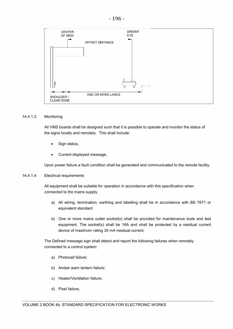
- 196 -
VOLUME 2 BOOK 4b: STANDARD SPECIFICATION FOR ELECTRONIC WORKS
14.4.1.3 Monitoring
All VMS boards shall be designed such that it is possible to operate and monitor the status of
the signs locally and remotely. This shall include:
• Sign status,
• Current displayed message,
Upon power failure a fault condition shall be generated and communicated to the remote facility.
14.4.1.4 Electrical requirements
All equipment shall be suitable for operation in accordance with this specification when
connected to the mains supply.
a) All wiring, termination, earthing and labelling shall be in accordance with BS 7671 or
equivalent standard
b) One or more mains outlet socket(s) shall be provided for maintenance tools and test
equipment. The socket(s) shall be 16A and shall be protected by a residual current
device of maximum rating 30 mA residual current.
The Defined message sign shall detect and report the following failures when remotely
connected to a control system:
a) Photocell failure;
b) Amber warn lantern failure;
c) Heater/Ventilation failure;
d) Pixel failure;

- 197 -
VOLUME 2 BOOK 4b: STANDARD SPECIFICATION FOR ELECTRONIC WORKS
e) Message Failure.
14.4.1.5 Interface requirements
The contractor shall provide adequate information relating to the interface requirements
between the Product and the equipment from which the Product is to be administered. The
contractor shall ensure that the supplied VMS and associated equipment is compatible with
existing VMS infrastructure and communications protocol.
It shall be the design Authority’s responsibility to ensure that the interface provided for the sign
is compatible with the sign control equipment.
Unless stated in the Procurement Contract, the Product interface shall be one or more of the
following:
• An RS485 2-wire interface
• RS232C, CCITT V24 and V28
• IEEE 802.3u/100Base-T.
14.4.1.5.1 RS232 interface protocol
Where specified the RS232C interface shall be used in association with a local monitor or via a
PSTN interface to a stand-alone message control system.
The message structure and protocol shall be as that defined for the Stand-alone Controller.
14.4.1.5.2 IEEE 802.3u interface
This interface can be used for both control and monitoring functions.
The information pages that contain all the operational logs, meta data and fault status shall be in
the form of HTML pages that can be accessed and viewed by an internet explorer utility.
Messaging and control shall also be accomplished via this interface where a digital wide area
network connection
14.4.1.6 Construction
The construction of the VMS shall comply with the following specifications:
a) Lighting units and controllers external to the enclosure of the product shall be protected
to IP65.
b) Means shall be provided to minimise the generation of condensation forming inside the
product such that the performance is not affected.

- 198 -
VOLUME 2 BOOK 4b: STANDARD SPECIFICATION FOR ELECTRONIC WORKS
c) Where the enclosure is fabricated from aluminium the materials used and structural
design shall conform to BS 8118 standard or equivalent and approved.
d) Where specified in the Works Specification, the Design Authority shall develop a
structurally compliant enclosure that meets requirements for a passively safe enclosure
that could be mounted on a lightweight gantry that conforms to BS EN 12767.
e) Variable message signs shall be equipped with a means of vertical and horizontal
adjustment so that the sign can be correctly aligned to maximise the benefit of the
angular field of display according to the carriageway alignment, gradient and vehicle
speed.
14.4.1.7 Portable VMS (Trailer mounted)
Under this item, the Contractor shall furnish, install, operate, maintain, relocate and remove
portable variable message signs (VMS) as ordered by the Employer. The portable VMS are
intended for use as temporary warning devices for lane and roadway closings and for conveying
such motorist information about construction as may be determined necessary by the Employer.
As such, it must be self-contained, easily moved and provide a clear, readable message from
roadside.
The portable VMS shall meet the requirements of this specification.
14.4.1.8 Materials
The Portable Variable Message Sign shall consist of the following major components:
• Message Board
• Operator Interface
• Power Supply
• Towable Trailer
These items shall be permanently mounted on a trailer to allow the Equipment to be transported
between sites. They shall be suitably housed to provide environmental and security protection
and prevent unauthorised operation.
14.4.1.9 Message board
14.4.1.9.1 Operating modes
The Display Panel shall have two ‘modes’:
a) Transportation Mode; this mode will be used for both transportation of the Equipment
and storage when non-operational.

- 199 -
VOLUME 2 BOOK 4b: STANDARD SPECIFICATION FOR ELECTRONIC WORKS
b) Operation Mode; this mode will be used at all times when the Equipment is required to
display a message.
Operation mode shall only be used when the Equipment is stationary. Once in Operation mode,
the lower edge of the Display Panel enclosure shall be between 2.13m and 2.50m above local
ground level measured to the parking area below the sign.
14.4.1.9.2 Housing
The message board housing shall be as follows:
a) The housing shall be a weatherproof aluminium enclosure, which shall not exceed
3300mm (length) x 2000mm (height) x 356mm (depth). The housing shall be finished
with one coat of corrosion inhibiting primer and two coats of flat black alkyd enamel
baked to the surface.
b) The message board front face shall provide a smooth, flat, scratch-resistant and
wipeclean surface that is predominantly non-reflective.
c) The housing shall incorporate drains in order to prevent any accumulation of water
which might give rise to condensation which may affect optical performance.
14.4.1.9.3 Display technology
The display shall use LED enhanced, reflectorized disks, arranged in a matrix for each character
that is 7 disks high x 5 disks wide.
14.4.1.9.4 Message Lines
Shall have the capabilities of displaying at least three lines of 457 mm characters with a
minimum of 8 characters per lines.
14.4.1.9.5 Character spacing
The spacing between characters shall be a minimum of 114 mm and between lines of minimum
of 171 mm.
14.4.1.9.6 Display colour
The display shall appear amber in colour when viewed from the front of the sign.
14.4.1.9.7 Illumination
The LED enhanced disks shall provide sufficient output illumination such that the display is
clearly legible from a distance of 274m under all lighting conditions. The illumination intensity
shall be automatically adjustable for various day and night-time ambient conditions.

- 200 -
VOLUME 2 BOOK 4b: STANDARD SPECIFICATION FOR ELECTRONIC WORKS
The design shall ensure that light sensors cover the whole range of light levels from full daylight
to darkness within their active operating range, with an accuracy of ± 2 Lux or 5%, whichever is
the greater.
14.4.1.9.8 Flashing lanterns
In addition to the character display matrix, flashing lanterns may be required.
The Display Panel shall incorporate four amber flashing Lanterns. These shall be 125mm in
diameter and controlled by the light sensors.
14.4.1.9.9 Operator interface
A means of controlling the display message at the site shall be provided with each sign. The
operator interface shall contain, as a minimum the following:
a) Operator’s Display
b) Input Device
c) Controller
The sign controller elements shall be housed in an IP65 lockable weatherproof enclosure.
All covers, doors, protective screens, plates, glands, external connectors etc. Necessary for
environmental protection, shall be provided with seals which are maintenance free and shall
remain effective for the design life of the equipment.
Where vents or grilles are provided, these shall be positioned and protected to prevent any
ingress of dirt and moisture and grilles shall be fitted with insect mesh.
14.4.1.9.10 Operator’s display
The operator’s display unit shall be located in one of the external equipment enclosure and shall
display a sufficient number of characters to allow the operator to preview the message content
and format before it is put upon the message board.
The display shall be mounted in such a manner (where possible) to allow the operator easy
access to it.
14.4.1.9.11 Input device
The input device supplied shall be a keyboard of standard design.
14.4.1.9.12 Controller
The controller shall have the capability of at least the following:
a) Store a minimum of 190 pre-defined messages.

- 201 -
VOLUME 2 BOOK 4b: STANDARD SPECIFICATION FOR ELECTRONIC WORKS
b) Store a minimum of 190 user-created messages.
c) Variable flash rate from 1 to 6 seconds.
d) Sequences of up to 6 messages for display.
e) Default message upon power loss.
The Controller shall:
a) Operate without user intervention for extended periods of time;
b) Restart upon power resumption, or a reset, without user intervention.
(N.B. In this case ‘without user intervention’ shall mean that no human interaction is required to
restart the equipment, acknowledge alarms, press keys, etc.)
The Local Controller shall incorporate a password or other means of protection to prevent
unauthorised setting of messages or changes to operational parameters.
a) Separate levels of access shall be provided as a minimum for ‘Operator’ and ‘Engineer’
access.
The Local Controller shall provide information to local users. This may be in the form or
individual status indicators or a display panel. The local information shall typically comprise:
a) Current configuration;
b) Any fault status;
c) Status of power supplies and stored charge.
The Local Controller shall include a hardware based ‘Watchdog’ facility which in the event of a
fatal fault shall automatically re-initialise the Equipment.
a) The occurrence of such events shall be recorded/latched within operational/fault logs
b) The occurrence of such events shall also be reported in accordance with the
Purchaser’s control system protocol when such a control system is enabled.
c) A ‘fatal fault’ shall be one which prevents a message from being correctly displayed, or
a major failure of an element of the VMS e.g. an electrical generator.
14.4.1.9.13 Communication
The system shall support an NTCIP 1203 conformant interface for exchanging data
14.4.1.9.14 Wired connection

- 202 -
VOLUME 2 BOOK 4b: STANDARD SPECIFICATION FOR ELECTRONIC WORKS
The system shall be capable of communication a wired telephone connection
14.4.1.9.15 Remote control
The system shall be capable of communication using a cellular telephone.
The Contractor shall be capable of monitoring sign status and changing standard messages
from a remote location as chosen by the Employer, by means of cellular phones. The cellular
phone communication scheme shall be compatible with the Authorities central control hardware.
One cellular phone and modem shall be supplied with each Potable Variable Message Sign.
14.4.1.9.16 Power supply
The Equipment shall be designed to operate from mains electricity supply and an internal set of
batteries. The Equipment shall be provided with an automatic changeover system between the
two energy sources.
The batteries provided shall be:
a) Sealed and maintenance free
b) Have a minimum design life of 24-months
c) Incorporate control circuits to prevent deep-discharging of any battery
The mains electricity connection point shall be rated at a minimum of IP44.
This external power supply shall operate the Display Panel and any onboard equipment, and
recharge the onboard energy store whenever connected and ‘live’.
The Equipment shall be provided with a main electrical isolation switch.
14.4.1.9.17 Towable trailer
The trailer shall be rugged construction suitable for towing at highway speeds and at low speed
over rugged construction site terrain. The trailer shall have at least the following features:
a) Complete lighting to standard highway specifications.
b) A single axle with two 381 mm wheels.
c) A hydraulic surge brake system.
d) 51 mm ball coupler with heavy duty safety chains.
e) 4 leveling jacks capable of leveling the trailer on 1 in 6 grade and capable of stabilizing
the trailer in high winds up to 129 km/h.

- 203 -
VOLUME 2 BOOK 4b: STANDARD SPECIFICATION FOR ELECTRONIC WORKS
The trailer shall be a maximum of 5 m long and a maximum 2.45 m wide. It shall have at least
the following sign positioning capabilities:
a) The sign shall be capable of being locked in a stowed position while being towed, with
no part of the equipment (including the message board, stabilizers and ancillary items)
extending beyond the main structure of the trailer.
b) A hydraulic lift mechanism shall be provided to elevate the sign to its operating position.
c) The sign shall be capable of 360° rotation and be capable of being locked in a selected
position.
14.4.1.9.18 Environment
The Portable Variable Message Sign shall be capable of performing all functions at ambient
temperature from -10°C to +50°C. There shall be no degradation of operation due to fog, rain,
or snow.
14.4.1.9.19 Security
The number of exposed nuts, bolts and other fixings shall be minimised. Where these features
cannot be avoided, the following minimum measures shall be applied:
a) Any exposed bolts shall be welded to the part they are securing
b) Any exposed bolts shall have a security head.
The Equipment shall be provided with a main securing point, to allow it to be chained to the
parking area. (N.B. this facility may be provided by placing a chain around a main structural
member of the trailer.)
The trailer shall be provided with a pair of wheel clamps to prevent the trailer being towed. Each
wheel clamp shall be secured by a padlock.
Each wheel shall be provided with at least one locking wheel nut. These shall NOT be of a
‘protruding-pin’ variety.
Each Enclosure shall be provided with a locking facility. Preference shall be given to Barker-
Nelson type locking and hinge mechanisms. Where padlocks are provided, it shall be enclosed
to prevent the lock from being forced open with a pry-bar.
Where a security fitting is provided for a padlock, it shall be supplied complete with a suitable
padlock.
a) All padlocks and padlock fittings shall be type-tested minimum grade 5.
b) Padlocks shall be closed or open shackle to suit the hasp.

- 204 -
VOLUME 2 BOOK 4b: STANDARD SPECIFICATION FOR ELECTRONIC WORKS
c) All individual padlocks supplied with a single Portable VMS shall be keyed-alike and
supplied with four number keys
If required by the Purchaser, that the Equipment shall include a radio-based tracking device.
This shall be linked to an inertial system which may be activated by the operator.
a) If activated, the inertial system shall trigger the tracking system if the Equipment is
moved.
b) The tracking system shall broadcast its current position to allow it to be located.
c) The tracking device shall be discretely and securely sited within the Equipment.
The onboard means of electricity generation shall be housed in a secure enclosure mounted
upon the Equipment trailer. Whilst it shall be possible to access and remove any means of
generation for maintenance the level of security shall not be compromised and shall take priority
over ease of maintenance.
14.4.1.9.20 Construction details
The Portable Variable Message Signs shall be placed and operated by the Contractor as
ordered by the Employer. The central location from which the signs will be operated, and the
messages to be displayed will be as directed by the Employer. The Contractor shall utilize a
central computer to control the variable message signs.
The signs shall be mounted such that the base of the display panel is at least 2 m above the
pavement surface and properly aligned to provide optimum viewing by approaching motorists.
The signs may require relocation or reorientation on daily basis or more frequently as ordered
by the Employer.
- 205 -
VOLUME 2 BOOK 4b: STANDARD SPECIFICATION FOR ELECTRONIC WORKS
S E C T ION 15 C C T V S UR V E IL L ANC E S Y S T E M

- 206 -
VOLUME 2 BOOK 4b: STANDARD SPECIFICATION FOR ELECTRONIC WORKS
15.1 S C OP E
This specification covers the requirements in respect of the components and subsystems of a
typical CCTV surveillance system.
15.1.1 System Function
15.1.1.1 The purpose of any CCTV system shall be to act as a deterrent and to provide general
surveillance of the nominated area.
15.1.1.2 The CCTV System shall be programmed so that any duress or alarm situation shall cause the
closest camera to the alarm/duress location be switched to an “Alarm Mode” which shall
increase the recording rate and display the image on a nominated monitor.
15.1.2 Alarm Handling
15.1.2.1 The system shall include a comprehensive suite of alarm handling routines. Upon receipt of an
alarm the associated video input(s) shall be switched to the programmed monitor output for
display along with a pre-programmed alarm enunciated message.
15.1.2.2 The video management system shall detect video signal failure and initiate an alarm for the
user.
15.2 IDE NT IF IC AT ION OB J E C T IV E
15.2.1 Definition
'Identification percentage' conveys how much of a person's body would be displayed on the
control room video monitor. It should be assumed that 100 % 'identification' is achieved when a
1,8 m tall person fills the vertical monitor screen height.
15.2.2 Classification
The following percentages shall apply:
• 5 % for crowd control monitoring,
• 10 % to detect a person,
• 50 % - 75 % for recognition of a known person,
• 50 % - 75 % for recognition of vehicle,
• 100 % - 120 % for identification of an unknown person.
- 207 -
VOLUME 2 BOOK 4b: STANDARD SPECIFICATION FOR ELECTRONIC WORKS
15.3 C AME R AS
15.3.1 General
Cameras shall have the following minimum specifications:
Commercial and/or domestic-grade video cameras shall not be acceptable. Cameras offered
shall have a MTBF exceeding 10 000 hours. MTTR/E shall be less than 24 hours.
15.3.2 High Speed Dome Cameras
Dome cameras shall be similar or equal to the Pelco Spectra IV, Environmentally Protected
Pendant Mount unit with a clear bubble.
15.3.2.1 General
The outdoor CCTV camera dome system shall be a discreet, miniature camera dome system
consisting of a dome drive with a variable speed/high speed pan and tilt drive unit with
continuous 360° rotation; 1/4-inch high resolution colour/black-white CCD camera; motorized
zoom lens with optical and digital zoom; auto focus; and an enclosure consisting of a back box,
lower dome, and a quick-install mounting.
The outdoor CCTV camera dome system shall meet or exceed the following design and
performance specifications.
15.3.2.2 Dome Drive
The variable speed/high speed pan and tilt dome drive unit shall meet or exceed the following
design and performance specifications.
a) Pan Speed: Variable between 400° per second continuous pan to 0.1° per second.
b) Vertical Tilt: Unobstructed tilt of +2° to -92°.
c) Manual Control Speed: Pan speed of 0.1° to 80° per second, and pan at 150° per
second in turbo mode. Tilt operation shall range from 0.1° to 40° per second.
d) Automatic Preset Speed: Pan speed of 400° and a tilt speed of 200° per second.
e) Presets: 256 positions with a 20-character label available for each position;
programmable camera settings, including selectable auto focus modes, iris level and
backlight compensation for each preset; command to copy camera settings from one
preset to another; and preset programming through control keyboard or through dome
system on-screen menu.
f) Preset Accuracy: ± 0.1°.

- 208 -
VOLUME 2 BOOK 4b: STANDARD SPECIFICATION FOR ELECTRONIC WORKS
g) Proportional Pan/Tilt Speed: Speed decreases in proportion to the increasing depth of
zoom.
h) Automatic Power-Up: User-selectable to the mode of operation. The dome will assume
when power is cycled, including an automatic return to position or function before power
outage.
i) Zones: Eight zones with up to 20-character labelling for each, with the ability to blank
the video in the zone.
j) Motor Drive: Cogged belt with 0.9° stepper motor.
k) Motor Operating Mode: Microstep to 0.015° steps.
l) Motor: Continuous duty and variable speed, operating at 18 to 32 VAC, 24 VAC
nominal.
m) Limit Stops: Programmable for manual panning, auto/random scanning, and frame
scanning.
n) Inner Liner: Rotating black ABS liner inside a sealed lower dome.
o) Alarm Inputs: Ability to control seven alarm inputs located in the back box.
p) Alarm Outputs: Ability to control one auxiliary Form C relay output and one open
collector auxiliary output located in the back box.
q) Alarm Output Programming: Auxiliary outputs can be alternately programmed to operate
on alarm.
r) Alarm Action: Individually programmed for three priority levels, initiating a stored pattern
or going to a pre-assigned preset position.
s) Resume after Alarm: After completion of alarm, dome returns to previously programmed
state or its previous position.
t) Window Blanking: Eight 4-sided, user-defined shapes, each side with different lengths;
window blanking setting to turn off at user-defined zoom ratio; window blanking set to
opaque grey or translucent smear; blank all video above user-defined tilt angle; blank all
video below user-defined tilt angle.
u) Patterns: Eight user-defined programmable patterns including pan, tilt, zoom, and
preset functions; and pattern programming through control keyboard or through dome
system on-screen menu.
v) Pattern Length: Eight patterns of user-defined length based on dome memory.

- 209 -
VOLUME 2 BOOK 4b: STANDARD SPECIFICATION FOR ELECTRONIC WORKS
w) Internal Clock: Internal system clock, user programmable for 12 or 24 hour day
format and mm/dd/yy or dd/mm/yy calendar format.
x) Scheduler: Internal scheduling system for programming presets, patterns, window
blanks, alarms, and auxiliary functions based on internal clock settings.
y) Menu System: Built-in setup of programmable functions in the English language.
z) Auto Flip: Rotates dome 180° at bottom of tilt travel.
aa) Password Protection: Programmable settings with optional password protection.
bb) Clear: Clear individual, grouped, or all programmed settings.
cc) Freeze Frame: Freeze current scene of video during preset movement.
dd) Display Setup: User-definable locations of all labels and displays and user-
selectable time duration of each display.
ee) Azimuth/Elevation/Zoom: On-screen display of pan and tilt locations and zoom ratio.
ff) Compass Display: On-screen display of compass heading and user-definable compass
setup.
gg) Camera Title Overlay: 20 user-definable characters on the screen camera title display.
hh) Video Output Level: User-selectable for normal or high output levels to compensate for
long video wire runs.
ii) Dome Drive Compatibility: All dome drives are compatible with all back box
configurations.
jj) RJ-45 Jack: Contains a plug-in jack on the dome drive for control and setup of the unit,
the uploading of new operating code and language file updates, compatible with
personal computers and PDAs such as Palm™ and iPAQ™.
kk) Remote Data Port Compatibility: Ability to set up and control unit, and upload new
operating code and language file updates through the easily accessible optional remote
data port. Remote data port compatible with personal computers and PDAs such as
Palm and iPAQ.
ll) Power Consumption: Maximum 70 VA
15.3.2.3 Camera module
The high resolution CCD camera shall meet or exceed the following design and performance
specifications.

- 210 -
VOLUME 2 BOOK 4b: STANDARD SPECIFICATION FOR ELECTRONIC WORKS
15.3.2.4 Colour/Black-White Optic System (35X)
a) Image Sensor: 1/4-inch EXview HAD™ CCD.
b) Scanning System: 2:1 interlaced output.
c) Effective Pixels: PAL: 752 x 582.
d) Horizontal Resolution: PAL: >540 TVL.
e) Lens: F1.4 (f=3.4 - 119 mm optical, 35X optical zoom, 12X digital zoom).
f) Programmable Zoom Speeds: 3.2, 4.6, or 6.6 seconds.
g) Horizontal Angle of View: 55.8° at 3.4 mm wide zoom, 1.7° at 119 mm telephoto zoom.
h) Focus: Automatic with manual override.
i) Sensitivity at 35 IRE
i. PAL/CCIR: 0.50 lux at 1/50 sec shutter speed (colour).
ii. 0.062 lux at 1/3 sec shutter speed (colour).
iii. 0.00014 lux at 1/1.5 sec shutter speed (B-W).
j) Synchronization System: Internal/AC line lock phase adjustable via remote control, V-
sync.
k) White Balance: Automatic with manual override.
l) Shutter Speed: PAL: 1/1.5-1/30,000.
m) Iris Control: Automatic with manual override.
n) Gain Control: Automatic/ off.
o) Video Output: 1 Vp-p, 75 ohms.
p) Video Signal-to-Noise: >50 dB.
q) Type of Lighting: Menu selection of indoor or outdoor lighting for optimum camera
performance.
r) Wide Dynamic Range: 128X.
s) Motion Detection: User-definable motion detection settings for each preset scene, can
activate auxiliary outputs, and contains three sensitivity levels per zone

- 211 -
VOLUME 2 BOOK 4b: STANDARD SPECIFICATION FOR ELECTRONIC WORKS
t) Electronic Image Stabilization: Electronic compensation for external vibration sources
that cause image blurring; User selectable for two frequency ranges, 5Hz (3-7Hz) and
10Hz (8-12Hz).
15.3.2.5 Back Box and Lower Dome (Pendant Environmental)
The back box and lower dome shall meet or exceed the following design and performance
specifications.
a) Connection to Dome Drive: Quick, positive mechanical and electrical disconnect without
the use of any tools.
b) Trap Door: Easy access trap door that allows complete access to the installation wiring,
and provides compete separation of the wiring from the dome drive mechanics when
closed.
c) Terminal Strips: Removable terminal strips with screw-type terminals for use with a wide
range of wire gauge sizes.
d) Auxiliary Connections: One Form-C relay output at <40 V, 2 A maximum and a second
open collector output at 32 VDC maximum at 30 mA.
e) Alarm Inputs: Seven alarm inputs.
f) Integrated UTP Circuit: Integrated circuit that converts video output to passive, UTP
transmission.
g) Fiber Optic Compatibility: Ability to plug into back box an optional Pelco fibre optic
module, or a third-party board that converts video output and control input for fibre optic
transmission.
h) Third-Party Control Systems: Ability to plug in an optional TXB board that converts
control signals from selected third-party controllers.
i) Installation: Quick-mount wall, corner, pole, parapet, or ceiling adapter.
j) Cable Entry: Through a 1.5-inch NPT fitting.
k) Environmental Features: Factory-installed heaters, blowers, and sun shroud.
l) Operating Temperatures: Maximum temperature range of -51.1° to 60°C for two hours,
and a continuous operating range of -51.1° to 50°C.
m) Memory: Built-in memory storage of camera and location- specific dome settings such
as presets and patterns. If new dome drive is installed in back box, all settings will
automatically download into new dome drive.
n) Colour: Gray, baked-on enamel powder coat.

- 212 -
VOLUME 2 BOOK 4b: STANDARD SPECIFICATION FOR ELECTRONIC WORKS
o) Construction: Aluminium.
p) Lower Dome Material: Acrylic, optically clear, with no distortion in any portion of the
dome up to +2 above the horizontal.
q) Dome Colour: Clear and smoked versions.
r) Trim Ring Connection: Two captivated screws
15.3.2.6 Dome System Dimensions
a) Diameter of Bubble: Maximum of 5.9 inches
b) Pendant, Environmental: 10.6-inch (26.9 cm) overall length (including dome) by 8.6-inch
(21.8 cm) diameter.
c) Dome System Weight.
d) Pendant, Environmental: 7.4 lb (3.34 kg)
15.3.2.7 Manufacturer’s Warranty
a) Repair or replacement of defective parts for a period of three years from the date of
shipment, including continuous motion modes.
15.3.2.8 Certifications and Ratings
a) CE: Class B.
b) UL Listed: FCC, Class B.
c) Meet NEMA Type 4X.
15.3.3 High Speed Dome Camera Platforms
15.3.3.1 General
a) The cameras shall be mounted on purpose-made stainless steel (ST316) brackets.
b) Cameras installed on the outside of building parapet walls shall be mounted on a hinged
stainless steel (ST316) supporting structure to facilitate maintenance inside the parapet
walls.
c) Unless specified to the contrary, cameras shall be installed on the Cueincident patented
pole with equipment housing or against concrete or masonry building structures to
minimise vibration.

- 213 -
VOLUME 2 BOOK 4b: STANDARD SPECIFICATION FOR ELECTRONIC WORKS
d) Poles can be considered for mounting heights up to 7m AFFL. Cueincident’s patented
camera poles are preferable to concrete camera poles or metal poles. All other metal
poles other than the Cueincident poles shall be stainless steel (ST316).
e) Poles shall be bolted onto concrete footings by means of stub poles cadge bolts.
Footings shall be designed to allow for the maximum wind load, based on the camera
windage area, as per the site meteorological data or to allow existing service to be
accommodated.
f) At 120 km/hr wind velocity, camera deflection shall not exceed 0,2 degrees.
g) Camera video and power cables shall be routed inside poles or masts.
h) Lattice - type camera masts will be preferred for camera mounting heights in excess of
7 m.
15.4 MONIT OR S
15.4.1 All operator monitors shall be minimum 17” LCD Flat Panel in size. The monitors may not be
required if a SCADA system is provided and the security system interfaced with the SCADA
system.
15.4.2 Video monitors shall include one or more of the following:
a) Set-up monitor located with the DVR (17” LCD/LED Flat Panel);
b) Working monitor (17” LCD/LED Flat Panel);
c) Alarm Monitor (17” LCD/LED Flat Panel);
15.4.3 Monitor Brackets
15.4.3.1 High-level monitor brackets shall conform, but not be limited to the following:
a) Appropriate bracket shall be provided to accommodate monitor size and weight.
b) Suspended from the ceiling or wall as agreed on-site.
c) Underside of the monitor mount to be a minimum of 2150 mm above finished floor level.
d) Securely mounted.
e) Allow monitor angle adjustment for optimum viewing.

- 214 -
VOLUME 2 BOOK 4b: STANDARD SPECIFICATION FOR ELECTRONIC WORKS
15.5 C AME R A MAS T S
15.5.1 General
The Contractor shall observe the requirements laid down by the civil aviation authorities and
shall ensure that all aviation lights and warning devices required, be provided and installed. The
Contractor shall, in this regard, obtain a directive (in writing) from the Department of Transport
and shall provide the Employer with a copy.
15.5.2 Mast construction
The mast shall be constructed from sections of no more than 3 m in length, joined together on
site to form a tapered lattice-work tower. The mast shall be designed in accordance to SABS
0162 and SABS 0160 Part 1 as amended, to withstand a wind velocity appropriate to the site,
with a mean return of 50 years. The deflection at the top of the mast shall not exceed
0,2 degrees of the mast height when subjected to 66 % of the maximum wind velocity.
The mast must be capable to withstand the maximum design conditions when fully equipped
with the specified cameras and associated equipment.
The mast shall be manufactured from high tensile steel to BS 4360 specification, having a
minimum tensile strength of 430 N/mm² with a wall thickness of 5 mm minimum. Mast sections
shall be spliced by means of M16 bolts. All sections of the mast, including all accessories shall
be galvanised inside as well as outside in accordance to SABS 763.
15.5.3 Ladders
Provision of caged ladders shall form part of the mast installation. Ladders shall be galvanised
and shall conform to the Occupational Health and Safety Act of 1993.
15.5.4 Mast foundation
A concrete foundation shall be provided for the mast. The Contractor shall allow for soil bearing
tests, design, excavations and provision of reinforcement, sleeve pipes, anchor plates, bolts,
concrete, etc required for the construction of the foundation.
Full design details of the foundations, including concrete mix and strengths, foundation bolts,
reinforcing required, soil pressure and overturning safety factors, as well as detailed
dimensioned drawings shall be submitted with tenders.
Soil bearing tests shall be conducted prior to finalising the design for the mast and its
foundation. Foundation design shall be certified by a registered professional engineer.
A minimum of 4 off 50 mm diameter uPVC sleeves with slow bends shall be cast into the
foundation to allow for cable entries.

- 215 -
VOLUME 2 BOOK 4b: STANDARD SPECIFICATION FOR ELECTRONIC WORKS
15.5.5 Lightning Protection
Lightning protection for the mast and equipment shall be provided in accordance to the
requirements of the SABS 03. A detailed design of the lightning protection system shall be
submitted to the Employer for approval before construction of the foundation commences.
15.5.6 Aviation lights
Statutory aviation warning beacons shall be installed at the top of the mast. 230 V AC beacon
light fitting with 11 W Dulux EL longlife compact fluorescent lamp shall be used for this purpose.
The light fitting shall have a red filter fresnel type glass lens and shall be protected against the
ingress of dust and moisture to IP 66. The fitting shall be finished in international orange, UV
stabilised powder coat. Cable entry shall be via a 20 mm ø bottom conduit entry. The fitting
shall be supplied complete with lamps and suitable mounting brackets. The beacon shall be the
“Waco satellite beacon" or similar and approved type.
15.6 C AME R A C AB L E C ONNE C T IONS
a) No exposed wiring/cabling shall be accepted. Cables shall be shielded and protected
by means of PVC spiral wrap protection at indoor cameras.
b) Outdoor cables shall be totally enclosed in black UV-resistant “Kopex” flexible conduit.
The conduit shall be terminated on either side by means of purpose made stainless
steel conduit connectors.
c) Outdoor cameras shall have in-line 75 ohm Eico, Dehn or Phoenix surge arrestors
inside the enclosure. The earth connection shall be bonded to the metal enclosure by
means of a 2,5 mm² green insulated earth wire.
d) Outdoor camera assemblies or brackets shall be earthed in accordance with the
General Specification.
15.7 DIG IT AL R E C OR DE R S
a) Digital recorders shall not employ magnetic tapes in cassette format.
b) The recorder shall as a minimum employ advanced selectable MJPEG and MPEG 4
video compression technology to record 25 images per camera per second on non-
volatile hard disk, regardless of camera system synchronisation, at a minimum
resolution of 704 x 288 pixels. The offered DVR’s shall accept a combination of
analogue and IP cameras on the same platform and is therefore classified as a
combined DVR / NVR.
c) The unit shall either utilise a ring memory management system or dual hard disk
storage mediums to guarantee un-interrupted recording.
d) The unit shall be controlled by RS 232 and LAN interface.

- 216 -
VOLUME 2 BOOK 4b: STANDARD SPECIFICATION FOR ELECTRONIC WORKS
e) Digital recorders offered shall have a minimum MTBF of 10 000 hrs at continuous use.
f) User-selected segments shall be marked/flagged to enable downloading of the selected
images to a DVD recorder or JAZ drive.
g) The recorder shall be suitable for 19 inch rack mounting.
h) File size calculations must be realistic and expected to fall in the range of 20-30Kb per
picture.
i) Systems using predictive software methods such as Wavelet will not be accepted.
j) Recorded images shall be encrypted so that they are admissible as evidence in a Court
of Law. Systems where the recording evidence has been accepted as admissible
evidence will receive preference. The Contractor will be required to submit confirmation
publications to this effect to become eligible for this preference.
k) Each DVR unit shall support up to 2000 Gbytes of internal SATA 2 hard discs and be
capable of supporting external hard disc storage in a RAID Level 5 configuration. Both
storage mediums are a requirement for this project whereby the RAID 5 units will be
used for field camera recordings and the internal storage units for recording the control
room cameras.
l) Each DVR unit shall be configured with an iSCSI HBA (Host Bus Adaptor) and an iSCSI
controlled RAID 5 unit with 6,5 TB (Terra Bytes) of SATA 2 hard disks. A hot swop drive
shall be included in the proposed system design. This will mean that 2 extra drives per
bay must be fitted i.e. one for the Raid 5 striping and one for the hot standby.
m) The DVR’s shall be connected to Cisco Gigabit switches. The individual HBA’s shall be
connected to one Gigabit switch array and the LAN connections of the DVR’s shall be
connected to a second array of Cisco Gigabit switches. This is to allow optimum data
transfer and sharing of resources. The second Cisco Gigabit switch array shall be
interconnected to the main system LAN.
n) The image quality/resolution shall be adjustable for each individual camera.
o) The digital recording must write to the data storage system on a FIFO (First In First Out)
principle for overwriting of old images.
p) There must be provision for dedicated space for specific cameras that may need
different recording and overwriting modes and several such recording rings must be
available.
q) The recording rate per camera shall be 25 images per second. However this image rate
shall be user adjustable per camera, as well as globally in increments of 1 image per
second. The recording rate for the control room cameras will be reduced to 4 images
per second.
- 217 -
VOLUME 2 BOOK 4b: STANDARD SPECIFICATION FOR ELECTRONIC WORKS
r) Facilities for Pre/Post Alarm Display alarm viewing of event sequences including pre-
history in a loop for single or multiple cameras shall be available, with user defined
times for the pre and post alarm sequences.
s) The main display shall be a SVGA monitor to view “quasi-live” images and archived
images.
t) Text detailing camera and time shall be able to be superimposed on the replayed digital
picture.
u) Playback enhancement of selectable regions of interest, including adjustment of
brightness, contrast and zooming shall be available. However, such adjustment shall
not alter the recoded data.
v) The system shall be capable of connection to the Ethernet network using TCP/IP
addressing.
w) View/review of the system via the network shall be possible using standard PC’s
(Windows) using supplied DVR application software.
x) It shall be possible for multiple PC’s to simultaneously access the DVR/s via the
network without limitation.
y) It shall be possible for a single workstation to simultaneously access several DVR’s via
the network without limitation.
z) The offered system shall be capable of video activity (presence) and full video motion
sensing (outdoor video motion detection - VMD). The Contractor shall advise how the
offered systems achieve these functions. This may become a future requirement and
the BOM has made provision for a cost rate.
aa) Alarm inputs for each camera shall be available to connect sensors and activate
recording. These alarm inputs shall allow the same “Input Event” programming and
controlling as defined in clause 7.10.8 below.
bb) A Time scheduler for time/date and event driven activities and recording parameters to
allow completely unattended operation shall be available to permit for example VMD to
be active during certain times, or contact inputs to be active/inactive during certain time
windows which are user defined.
cc) Start-up profiles. The system shall permit definition of user settings and viewer display
settings (even from several server connections) during start-up or after power
interruption.
dd) Password Protection. The system shall permit different levels of access which are user
definable and password protected.

- 218 -
VOLUME 2 BOOK 4b: STANDARD SPECIFICATION FOR ELECTRONIC WORKS
ee) Evidence Back-up. Evidence to be backed up using CD-R/DVD. Image sequences
downloaded to the CD-R/DVD must be in an "encrypted" format and append
automatically a "decode viewer" at the end of the back-up process. In this way the
encrypted pictures shall be viewed on a PC without compromising its integrity and
requiring review software to be loaded.
15.8 MAT R IX S WIT C H
15.8.1 The matrix switch required to manage the camera system shall conform, but is not limited to the
following:
a) The video matrix switch shall have a capacity to connect all cameras, monitors and
keyboards with a spare capacity of at least 30%.
b) Provide sufficient alarm inputs (make contact or open collector input) for all functions
with an additional 30% spare capacity.
c) Provide sufficient relay outputs (make contact or open collector input) for all functions
with an additional 30% spare capacity.
d) All video inputs of the matrix switch shall include down frame looping cards (DFL), the
looping output of the down frame looping cards shall be connected to an input of a DVR.
e) All video signals shall be looped through a Patch Panel before being routed through to
the matrix switcher.
f) Shall automatically switch a camera image to the console monitor on an alarm.
g) Shall be password protected with least two access levels.
15.9 E S S E NT IAL OP E R AT IONAL R E QUIR E ME NT S
The system shall provide the following operational features.
a) Simultaneous picture recording, playback and transmission.
b) The VGA screen shall be able to show all cameras using multi-screen viewing and be
possible to view simultaneously both current and archived moving pictures from the
same camera or camera groups.
c) Search by time, date, camera number, event, or using movement detection via a simple
user friendly window to allow instant retrieval.
d) Picture Search using time, date and camera number and alarm event list.
e) Synchronised Search of multiple cameras. Also from one or more than one Digital Video
Recorder - simultaneously in case an incident crosses a camera group connected to
more than one DVR machine.

- 219 -
VOLUME 2 BOOK 4b: STANDARD SPECIFICATION FOR ELECTRONIC WORKS
f) Synchronised Playback of multiple cameras on screen with both live and recorded data
simultaneously available. From one or more than one Digital Video Recording
simultaneously in case in case an incident crosses a camera group connected to more
than one DVR machine.
g) Bookmark lists to mark and quickly retrace once-found pictures for closer scrutiny.
h) Motion Search as search function on recorded pictures to search either backwards or
forwards through the database.
i) Motion detection as a live “Guard” function on quasi-live pictures.
j) Multi-screen display of pictures for search/playback/quasi-real-time viewing 1, 4, 9, 16,
and 36 windows.
k) Export Images as standard picture files e.g. bitmap for importation into email or
documents etc.
l) Export Images as encrypted picture files to both local CD-R/DVD and via network to
remote PC’s so that any back-up carried out remotely has same evidential value as
back-up locally.
m) Permit user templates to be constructed so any camera/camera group may be
presented on-screen by a single mouse click.
n) Independent Certification. Preference will be given to products with UVV Kassen and
UL certification. The Contractor shall state the certification of their offered system.
o) The system shall include a comprehensive suite of alarm handling routines. Upon
receipt of an alarm the associated video input(s) shall be switched to the programmed
monitor output for display along with a pre-programmed alarm enunciated message.
The appropriate alarms that trigger the video surveillance system will include but not be
limited to:
i. Use of an intercom station,
ii. Monitored points,
iii. Door open too long,
iv. Door forced alarms and
v. Duress alarms, etc., associated in the general vicinity of a video surveillance
camera.
p) The video management system shall detect video signal failure and initiate an alarm for
the user.

- 220 -
VOLUME 2 BOOK 4b: STANDARD SPECIFICATION FOR ELECTRONIC WORKS
S E C T ION 16 INS P E C T IONS , T E S T ING , C OMMIS S IONING AND HANDING
OV E R

- 221 -
VOLUME 2 BOOK 4b: STANDARD SPECIFICATION FOR ELECTRONIC WORKS
16.1 P HY S IC AL INS P E C T ION P R OC E DUR E -
16.1.1 On completion of the Installation or before any inspection or testing is required, the Contractor
shall carry out his own inspections to ensure that the installation and equipment comply with the
Specifications and that the quality of workmanship and materials are to the specified standards.
16.1.2 The Employer will not act as the Contractor’s inspector or quality control official.
16.1.3 Once the Contractor has completed the installation, written notice shall be given to the Employer
in order that a mutually acceptable date can be arranged for a joint inspection.
16.1.4 During the course of the inspection, the representative of the Employer will compile a list of
items (if any) requiring further attention. A copy of this list will be provided to the Contractor who
will have a period of 7 days in which to rectify the listed items.
16.1.5 The Contractor shall then provide written notice that he is ready for an inspection of the remedial
work to the offending items.
16.1.6 This procedure will continue until the entire installation has been correctly completed in
accordance with the specifications.
16.1.7 After the First inspection, all time and travelling costs incurred by the Employer for further
inspections or re-inspections will be payable by the Contractor.
16.2 F AC T OR Y INS P E C T IONS AND T E S T S
16.2.1 The Contractor shall advise the Employer in writing of any routine, type or specific tests to be
carried out on equipment during the course of manufacture in the manufacturer’s factory or
works or of any stage of completion in the manufacturing process which requires inspections in
terms of the Contract and Specifications.
16.2.2 Such notice shall be given at least 7 days prior to the testing or inspection being required. The
Contractor will dispatch equipment from the factory at his own risk if tests have not been
witnessed and inspections not been carried out by the Employer or his authorized
representative and approval given by the Employer for dispatch.
16.2.3 The Contractor’s Project Engineer shall in all instances do his own inspections and ascertain
that equipment will be ready for inspection or testing before the Employer's attendance is
requested. The Employer also reserves the right to inspect any equipment at the
manufacturer’s works at any stage during the manufacture.
16.2.4 The Contractors Project Engineer will also be required to attend all inspections and tests with
the Employer or his authorized representative.
16.3 T E S T ING AND OP E R AT IONAL INS P E C T ION P R OC E DUR E OF
INS T AL L AT IONS

- 222 -
VOLUME 2 BOOK 4b: STANDARD SPECIFICATION FOR ELECTRONIC WORKS
16.3.1 The Contractor shall have the complete installation tested and approved by the local authorities
where applicable.
16.3.2 Subsequent to the above testing and approval, the Contractor shall in the presence of the
Employer test all circuits with respect to:
16.3.2.1 Polarity
16.3.2.2 Phase balance
16.3.2.3 Insulation level
16.3.2.4 Earth Continuity
16.3.2.5 Earth leakage relay sensitivity
16.3.2.6 Trip testing and proving of all protection equipment .
16.3.2.7 A certified schedule of all measured values shall be submitted to the Employer.
16.3.3 Upon completion of the installation and within 3 months of the handover date, the Contractor
shall provide a recording voltmeter to record the voltage at three locations in the complex over a
period of 48 hours each. These locations will be nominated by the Employer.
16.4 T Y P E T E S T S , T E S T C E R T IF IC AT E S AND S P E C IAL IZE D T E S T S
16.4.1 The Contractor shall submit one copy of each of all the type test certificates called for in the
Specifications.
16.4.2 All tests shall be carried out in accordance with the requirements of the specified and
recognized standards. Where tests have not been detailed in the documents, the Contractor
shall provide comprehensive documentation of the standards and procedures he intends using
in testing.
16.4.3 Such additional tests in the manufacturer's works, on site or elsewhere as in the opinion of the
Employer are necessary to determine that the contract works comply with the specifications may
be called for. The general principle regarding payment of such tests shall apply i.e. the tests will
be paid for if they are additional to those specified however, payment will in all cases only be
made for tests with positive results. Retest will in no circumstances be paid for.
16.4.4 The Contractor will be required to submit certified copies of all type, routine and rating test
certificates to the Employer.
16.5 " AS B UIL T " DR AWING S , MAINT E NANC E AND OP E R AT ING MANUAL S
16.5.1 As each portion of the work is completed, the Contractor shall provide the Employer with “as
built” drawings, maintenance and operating manuals and other documents which are called for
in the Standard Technical Specification, the Detail Technical Specification or any other
specification or documentation forming part of this contract or as agreed to.

- 223 -
VOLUME 2 BOOK 4b: STANDARD SPECIFICATION FOR ELECTRONIC WORKS
16.5.2 Where “as built” layout drawings are required and where such electrical layouts are drawn on
Architectural drawings, the Employer will supply cad drawings of the Architectural drawings on
request at the current market costs to enable the Contractor to accurately detail the completed
installation. The Contractor shall obtain his own "base'” material and information for all
workshop, design, schematic and wiring diagrams or other drawing which must be provided as
built.
16.5.3 In addition, a complete reticulation and schematic diagram showing all supply cables and
switchboards or other equipment shall be provided in an electronic cad or PDF file version
behind a clean plastic cover in the substation or adjacent to the Main Switchboard if not located
in a substation.
16.5.4 The Contractor shall, before the works are taken over by the Employer provide two complete
sets of Operating and Maintenance Manuals together with drawings and technical data sheets
of the works as completed in sufficient detail to enable the Employer to maintain, dismantle, re-
assemble and adjust all parts of the works. A copy of the manuals and drawings shall also be
available in PDF format.
16.5.5 The installation will not be regarded as complete until all of the requirements of this section have
been met.
16.6 C OMMIS S IONING
16.6.1 The installation shall be comprehensively Commissioned as individual and integrated systems
as may be required by the configuration after the works are substantially complete.
16.6.2 The Contractor shall provide adequate and competent personnel for Commissioning of every
particular installation and for the full duration of the Commissioning process.
16.6.3 The Commissioning shall include interaction between other services and Contractors where
interdependence of installations is encountered.
16.6.4 The Commissioning process shall, after all testing has been completed be the final proving
ground of the systems and during this procedure the installations shall be subjected to all
possible inputs and actions which way be encountered under operational conditions. The
Contractor shall prove the full operation, working and compliance of the installation in
accordance with the specifications.
16.6.5 A programme of the planned Commissioning procedures shall be submitted to the Employer at
least 28 days before Commissioning commences to enable the Employer to witness the
Commissioning.
16.7 DOC UME NT AT ION
16.7.1 All documentation on the testing, Operational, Maintenance test certificates, “as built” drawings,
etc shall be available in electronic (PDF file format) and stored on the SCADA system.