south main corridor improvement project 2021-03-02 stp
TRANSCRIPT
South Main Corridor Improvement Project 2021-03-02
STP-4300 (112)
City of Maryville, MO
ADDENDUM 2 00911 - 1
SECTION 00911 - ADDENDUM 2
PART 1 - GENERAL
1.1 PROJECT INFORMATION
A. Project Name: South Main Corridor Improvement Project
B. Engineer: SK Design Group, Inc.
C. Engineer's Project Number: 16-108.
D. Date of Addendum: March 2, 2021
1.2 NOTICE TO BIDDERS
A. This Addendum is issued to all registered plan holders pursuant to the Instructions to Bidders and
Conditions of the Contract. This Addendum serves to clarify, revise, and supersede information
in the Project Manual, Drawings, and previously issued Addenda. Portions of the Addendum
affecting the Contract Documents will be incorporated into the Contract by enumeration of the
Addendum in the Owner/Contractor Agreement.
B. The Bidder shall acknowledge receipt of this Addendum in the appropriate space on the Bid Form.
C. The date for receipt of bids is unchanged by this Addendum at same time and location.
1.3 ATTACHMENTS
A. This Addendum includes the following attached Documents:
1. Prebid agenda and attendance sheet
2. Revised specification section Table of Contents
3. Geotechnical Reports.
1.4 GENERAL REVISIONS
A. Questions and answers:
1. HDPP pipe for crossroad pipes
a. Question: Is HDPP pipe allowed for crossroad pipes in lieu of RCP if the trench is
flow filled to the sub-grade.
b. Answer: The use of high-density polypropylene pipe (HDPP), meeting the
requirements of MODOT specifications section 724 for crossroad pipes in lieu of
RCP is acceptable, provided that the pipe is bedded properly per manufacturer
recommendation and the trench is backfilled with flowable fill up to the subgrade of
the pavement.
South Main Corridor Improvement Project 2021-03-02
STP-4300 (112)
City of Maryville, MO
ADDENDUM 2 00911 - 2
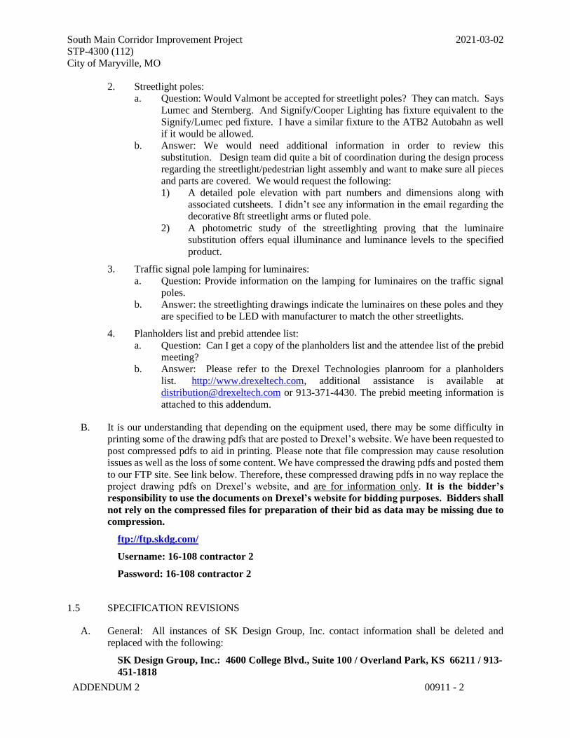
2. Streetlight poles:
a. Question: Would Valmont be accepted for streetlight poles? They can match. Says
Lumec and Sternberg. And Signify/Cooper Lighting has fixture equivalent to the
Signify/Lumec ped fixture. I have a similar fixture to the ATB2 Autobahn as well
if it would be allowed.
b. Answer: We would need additional information in order to review this
substitution. Design team did quite a bit of coordination during the design process
regarding the streetlight/pedestrian light assembly and want to make sure all pieces
and parts are covered. We would request the following:
1) A detailed pole elevation with part numbers and dimensions along with
associated cutsheets. I didn’t see any information in the email regarding the
decorative 8ft streetlight arms or fluted pole.
2) A photometric study of the streetlighting proving that the luminaire
substitution offers equal illuminance and luminance levels to the specified
product.
3. Traffic signal pole lamping for luminaires:
a. Question: Provide information on the lamping for luminaires on the traffic signal
poles.
b. Answer: the streetlighting drawings indicate the luminaires on these poles and they
are specified to be LED with manufacturer to match the other streetlights.
4. Planholders list and prebid attendee list:
a. Question: Can I get a copy of the planholders list and the attendee list of the prebid
meeting?
b. Answer: Please refer to the Drexel Technologies planroom for a planholders
list. http://www.drexeltech.com, additional assistance is available at
[email protected] or 913-371-4430. The prebid meeting information is
attached to this addendum.
B. It is our understanding that depending on the equipment used, there may be some difficulty in
printing some of the drawing pdfs that are posted to Drexel’s website. We have been requested to
post compressed pdfs to aid in printing. Please note that file compression may cause resolution
issues as well as the loss of some content. We have compressed the drawing pdfs and posted them
to our FTP site. See link below. Therefore, these compressed drawing pdfs in no way replace the
project drawing pdfs on Drexel’s website, and are for information only. It is the bidder’s
responsibility to use the documents on Drexel’s website for bidding purposes. Bidders shall
not rely on the compressed files for preparation of their bid as data may be missing due to
compression.
ftp://ftp.skdg.com/
Username: 16-108 contractor 2
Password: 16-108 contractor 2
1.5 SPECIFICATION REVISIONS
A. General: All instances of SK Design Group, Inc. contact information shall be deleted and
replaced with the following:
SK Design Group, Inc.: 4600 College Blvd., Suite 100 / Overland Park, KS 66211 / 913-
451-1818
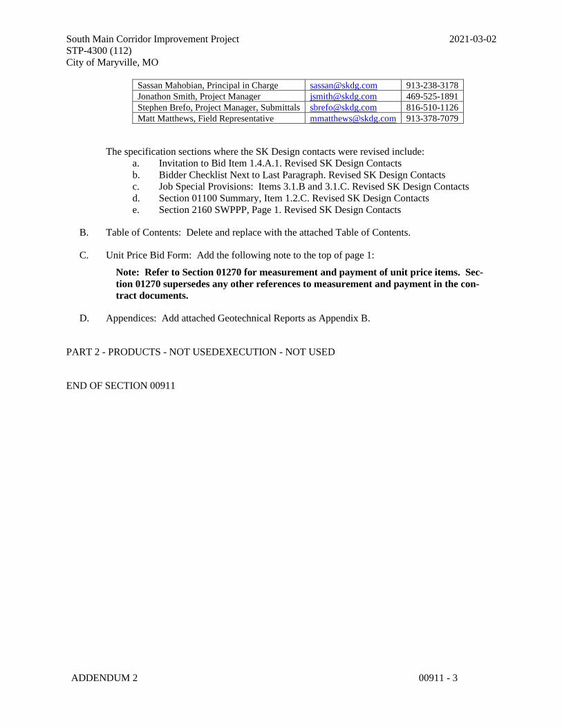
South Main Corridor Improvement Project 2021-03-02
STP-4300 (112)
City of Maryville, MO
ADDENDUM 2 00911 - 3
Sassan Mahobian, Principal in Charge [email protected] 913-238-3178
Jonathon Smith, Project Manager [email protected] 469-525-1891
Stephen Brefo, Project Manager, Submittals [email protected] 816-510-1126
Matt Matthews, Field Representative [email protected] 913-378-7079
The specification sections where the SK Design contacts were revised include:
a. Invitation to Bid Item 1.4.A.1. Revised SK Design Contacts
b. Bidder Checklist Next to Last Paragraph. Revised SK Design Contacts
c. Job Special Provisions: Items 3.1.B and 3.1.C. Revised SK Design Contacts
d. Section 01100 Summary, Item 1.2.C. Revised SK Design Contacts
e. Section 2160 SWPPP, Page 1. Revised SK Design Contacts
B. Table of Contents: Delete and replace with the attached Table of Contents.
C. Unit Price Bid Form: Add the following note to the top of page 1:
Note: Refer to Section 01270 for measurement and payment of unit price items. Sec-
tion 01270 supersedes any other references to measurement and payment in the con-
tract documents.
D. Appendices: Add attached Geotechnical Reports as Appendix B.
PART 2 - PRODUCTS - NOT USEDEXECUTION - NOT USED
END OF SECTION 00911
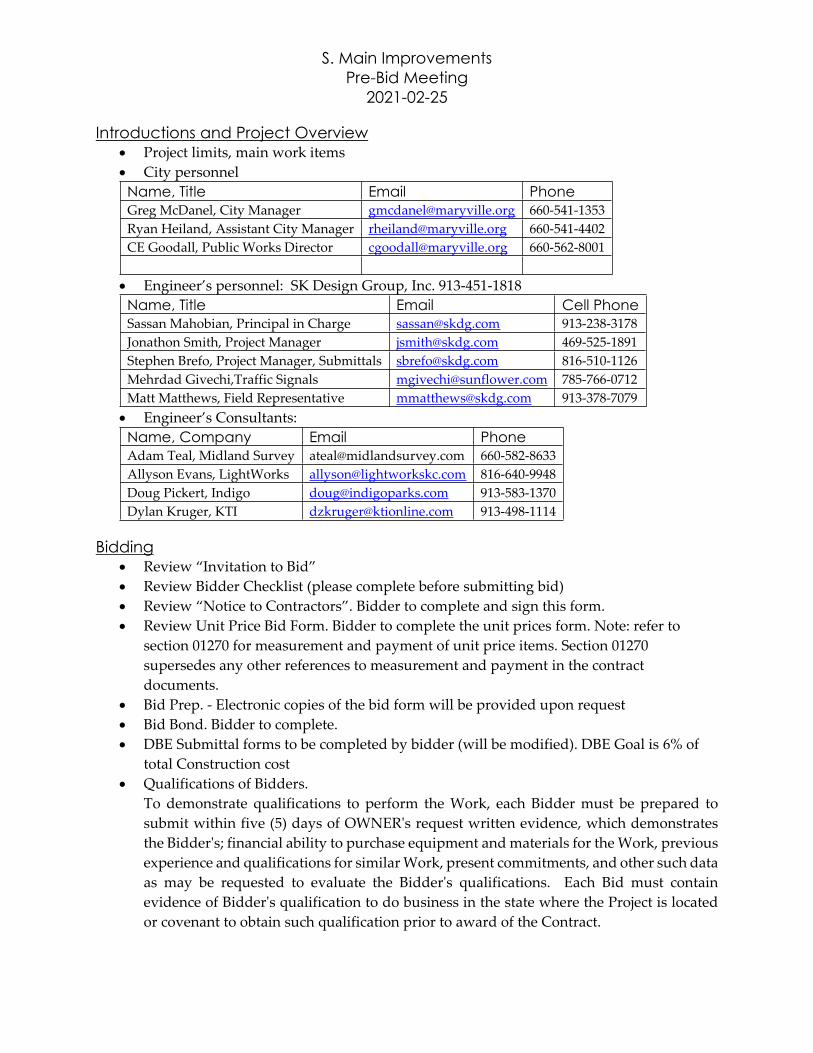
S. Main Improvements
Pre-Bid Meeting
2021-02-25
Introductions and Project Overview Project limits, main work items
City personnel
Name, Title Email Phone
Greg McDanel, City Manager [email protected] 660-541-1353
Ryan Heiland, Assistant City Manager [email protected] 660-541-4402
CE Goodall, Public Works Director [email protected] 660-562-8001
Engineer’s personnel: SK Design Group, Inc. 913-451-1818
Name, Title Email Cell Phone
Sassan Mahobian, Principal in Charge [email protected] 913-238-3178
Jonathon Smith, Project Manager [email protected] 469-525-1891
Stephen Brefo, Project Manager, Submittals [email protected] 816-510-1126
Mehrdad Givechi,Traffic Signals [email protected] 785-766-0712
Matt Matthews, Field Representative [email protected] 913-378-7079
Engineer’s Consultants:
Name, Company Email Phone
Adam Teal, Midland Survey [email protected] 660-582-8633
Allyson Evans, LightWorks [email protected] 816-640-9948
Doug Pickert, Indigo [email protected] 913-583-1370
Dylan Kruger, KTI [email protected] 913-498-1114
Bidding Review “Invitation to Bid”
Review Bidder Checklist (please complete before submitting bid)
Review “Notice to Contractors”. Bidder to complete and sign this form.
Review Unit Price Bid Form. Bidder to complete the unit prices form. Note: refer to
section 01270 for measurement and payment of unit price items. Section 01270
supersedes any other references to measurement and payment in the contract
documents.
Bid Prep. - Electronic copies of the bid form will be provided upon request
Bid Bond. Bidder to complete.
DBE Submittal forms to be completed by bidder (will be modified). DBE Goal is 6% of
total Construction cost
Qualifications of Bidders.
To demonstrate qualifications to perform the Work, each Bidder must be prepared to
submit within five (5) days of OWNER's request written evidence, which demonstrates
the Bidder's; financial ability to purchase equipment and materials for the Work, previous
experience and qualifications for similar Work, present commitments, and other such data
as may be requested to evaluate the Bidder's qualifications. Each Bid must contain
evidence of Bidder's qualification to do business in the state where the Project is located
or covenant to obtain such qualification prior to award of the Contract.
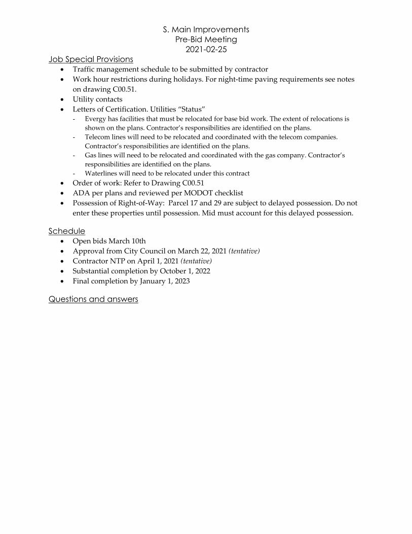
S. Main Improvements
Pre-Bid Meeting
2021-02-25
Job Special Provisions Traffic management schedule to be submitted by contractor
Work hour restrictions during holidays. For night-time paving requirements see notes
on drawing C00.51.
Utility contacts
Letters of Certification. Utilities “Status”- Evergy has facilities that must be relocated for base bid work. The extent of relocations is
shown on the plans. Contractor’s responsibilities are identified on the plans.
- Telecom lines will need to be relocated and coordinated with the telecom companies.
Contractor’s responsibilities are identified on the plans.
- Gas lines will need to be relocated and coordinated with the gas company. Contractor’s
responsibilities are identified on the plans.
- Waterlines will need to be relocated under this contract
Order of work: Refer to Drawing C00.51
ADA per plans and reviewed per MODOT checklist
Possession of Right-of-Way: Parcel 17 and 29 are subject to delayed possession. Do not
enter these properties until possession. Mid must account for this delayed possession.
Schedule Open bids March 10th
Approval from City Council on March 22, 2021 (tentative)
Contractor NTP on April 1, 2021 (tentative)
Substantial completion by October 1, 2022
Final completion by January 1, 2023
Questions and answers
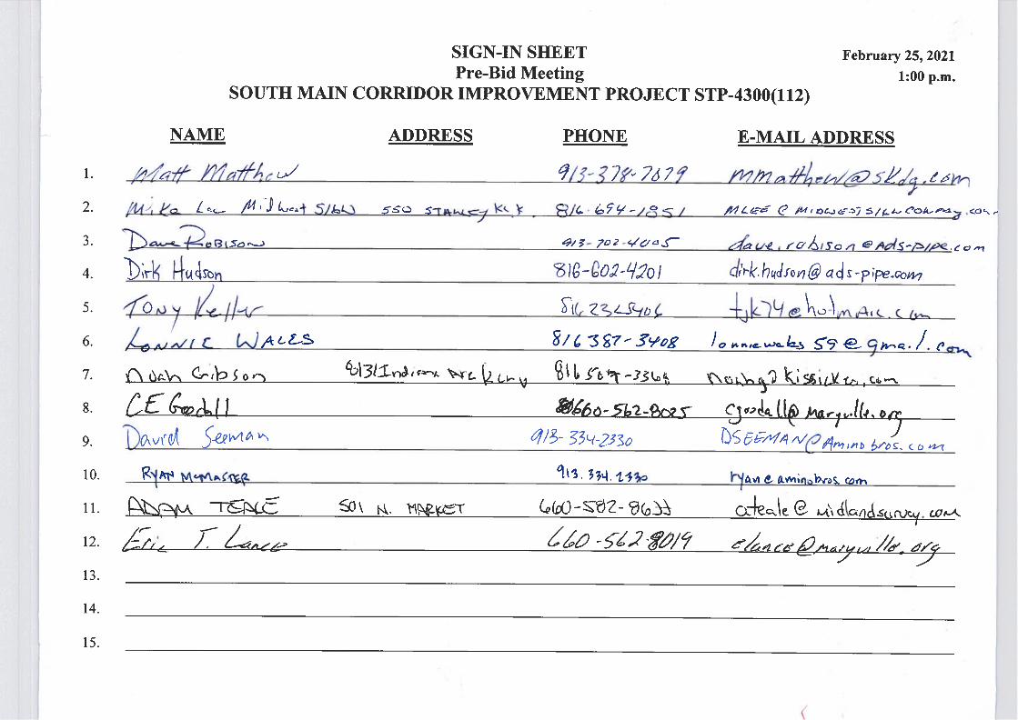
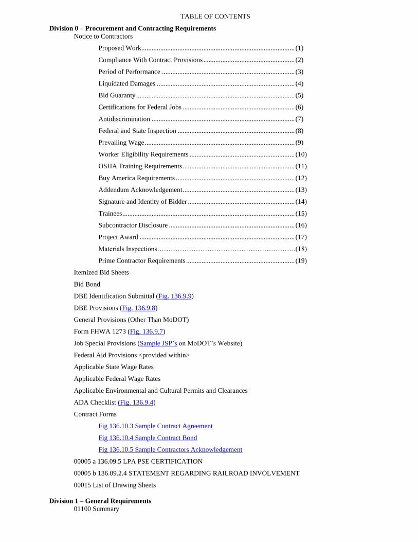
TABLE OF CONTENTS
Division 0 – Procurement and Contracting Requirements
Notice to Contractors
Proposed Work ......................................................................................... (1)
Compliance With Contract Provisions ..................................................... (2)
Period of Performance ............................................................................. (3)
Liquidated Damages ................................................................................ (4)
Bid Guaranty ............................................................................................ (5)
Certifications for Federal Jobs ................................................................. (6)
Antidiscrimination ................................................................................... (7)
Federal and State Inspection .................................................................... (8)
Prevailing Wage ....................................................................................... (9)
Worker Eligibility Requirements ............................................................. (10)
OSHA Training Requirements ................................................................. (11)
Buy America Requirements ..................................................................... (12)
Addendum Acknowledgement ................................................................. (13)
Signature and Identity of Bidder .............................................................. (14)
Trainees .................................................................................................... (15)
Subcontractor Disclosure ......................................................................... (16)
Project Award .......................................................................................... (17)
Materials Inspections…………………………………………………….(18)
Prime Contractor Requirements ............................................................... (19)
Itemized Bid Sheets
Bid Bond
DBE Identification Submittal (Fig. 136.9.9)
DBE Provisions (Fig. 136.9.8)
General Provisions (Other Than MoDOT)
Form FHWA 1273 (Fig. 136.9.7)
Job Special Provisions (Sample JSP’s on MoDOT’s Website)
Federal Aid Provisions <provided within>
Applicable State Wage Rates
Applicable Federal Wage Rates
Applicable Environmental and Cultural Permits and Clearances
ADA Checklist (Fig. 136.9.4)
Contract Forms
Fig 136.10.3 Sample Contract Agreement
Fig 136.10.4 Sample Contract Bond
Fig 136.10.5 Sample Contractors Acknowledgement
00005 a 136.09.5 LPA PSE CERTIFICATION
00005 b 136.09.2.4 STATEMENT REGARDING RAILROAD INVOLVEMENT
00015 List of Drawing Sheets
Division 1 – General Requirements
01100 Summary

01250 Contract Modification Procedures
01270 Unit Prices
01290 Payment Procedures
01310 Project Management and Coordination
01320 Construction Progress Documentation
01322 Photographic Documentation
01330 Submittal Procedures
01400 Quality Requirements
01550 Temporary Facilities and Controls
01635 Substitution Procedures
01770 Closeout Procedures
01781 Project Record Documents
01782 Operaion and Maintenance Data
Technical Specifications
2100 Clearing and Grading
2150 Erosion and Sediment Control
2160 SWPPP
2200 Paving
2300 Incidental Construction
2400 Seeding Sodding and Overseeding
2410 Landscape Work
2600 Storm Sewers
2800a Street Lights
2800bcd Roadway Lighting
2900 Waterlines
Appendix
Evergy Underground Construction Specification
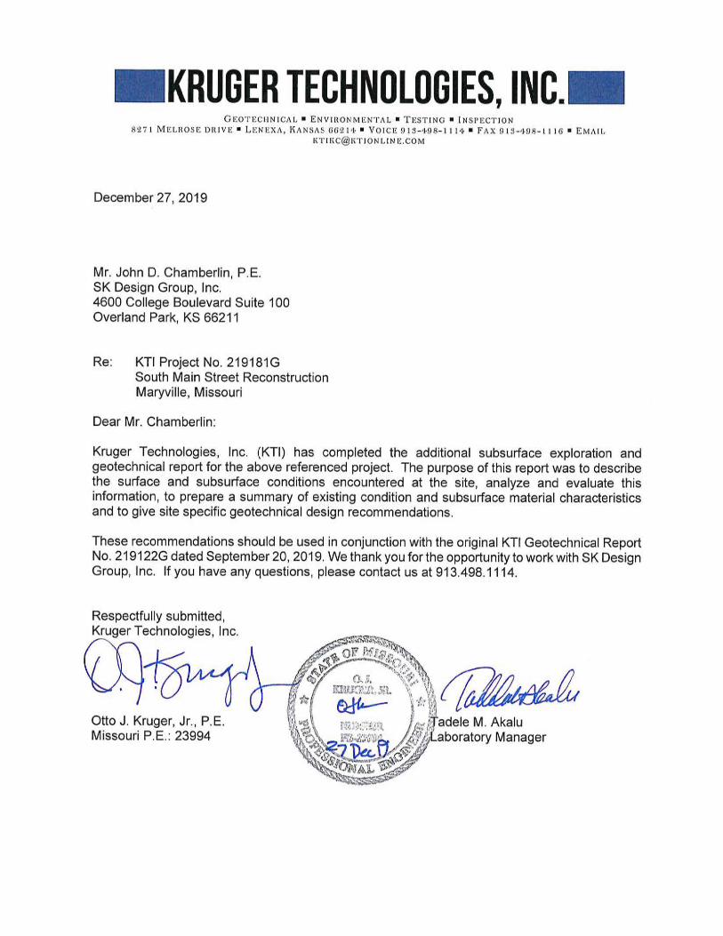
KTI Project No. 219181G December 27, 2019
i
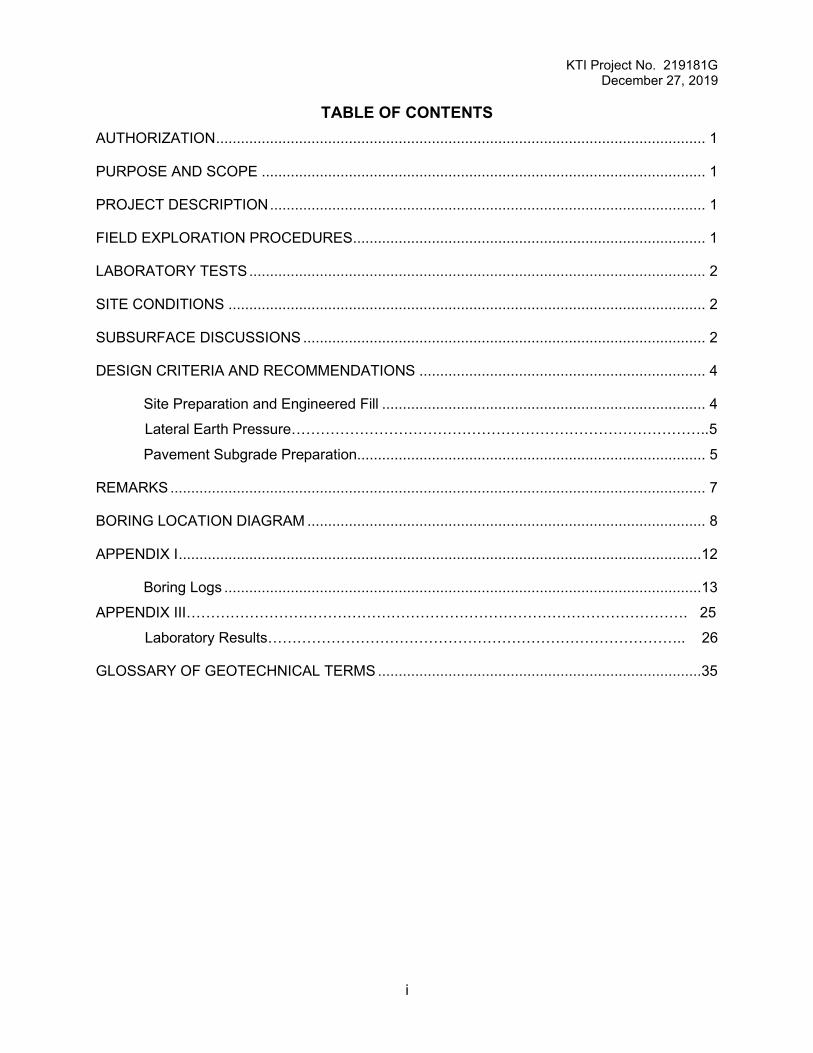
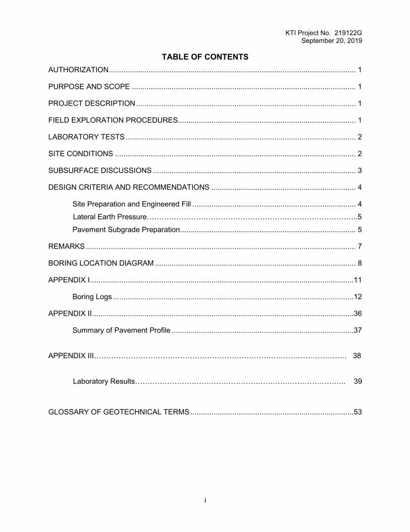
TABLE OF CONTENTS AUTHORIZATION ...................................................................................................................... 1
PURPOSE AND SCOPE ........................................................................................................... 1
PROJECT DESCRIPTION ......................................................................................................... 1
FIELD EXPLORATION PROCEDURES..................................................................................... 1
LABORATORY TESTS .............................................................................................................. 2
SITE CONDITIONS ................................................................................................................... 2
SUBSURFACE DISCUSSIONS ................................................................................................. 2
DESIGN CRITERIA AND RECOMMENDATIONS ..................................................................... 4
Site Preparation and Engineered Fill .............................................................................. 4
Lateral Earth Pressure…………………………………………………………………………..5
Pavement Subgrade Preparation .................................................................................... 5
REMARKS ................................................................................................................................. 7
BORING LOCATION DIAGRAM ................................................................................................ 8
APPENDIX I ..............................................................................................................................12
Boring Logs ...................................................................................................................13
APPENDIX III…………………………………………………………………………………………. 25
Laboratory Results………………………………………………………………………….. 26
GLOSSARY OF GEOTECHNICAL TERMS ..............................................................................35
KTI Project No. 219181G December 27, 2019
1
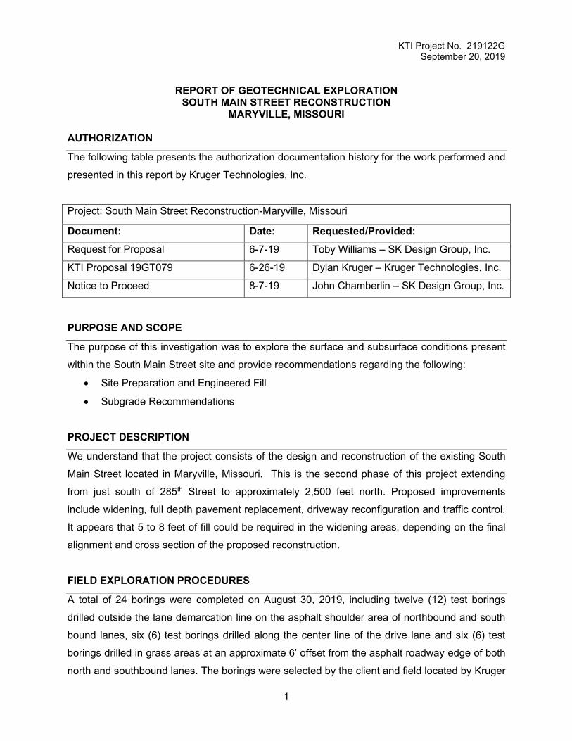
REPORT OF GEOTECHNICAL EXPLORATION
SOUTH MAIN STREET RECONSTRUCTION MARYVILLE, MISSOURI
AUTHORIZATION
The following table presents the authorization documentation history for the work performed and
presented in this report by Kruger Technologies, Inc.
Project: South Main Street Reconstruction-Maryville, Missouri
Document: Date: Requested/Provided: Request for Proposal 11-20-19 John Chamberlin – SK Design Group, Inc.
KTI Proposal 19GT200 11-22-19 Dylan Kruger – Kruger Technologies, Inc.
Notice to Proceed 11-22-19 John Chamberlin – SK Design Group, Inc.
PURPOSE AND SCOPE
The purpose of this investigation was to explore the surface and subsurface conditions present
within the South Main Street site and provide recommendations regarding the following:
• Site Preparation and Engineered Fill
• Lateral Earth Pressure
• Subgrade Recommendations
PROJECT DESCRIPTION
We understand that the project consists of the design and reconstruction of the existing South
Main Street and the intersection at South Avenue located in Maryville, Missouri. Proposed
improvements include widening, partial and full depth pavement replacement, driveway
reconfiguration and traffic control. It appears that 5 to 8 feet of fill could be required in the widening
areas, depending on the final alignment and cross section of the proposed reconstruction.
FIELD EXPLORATION PROCEDURES
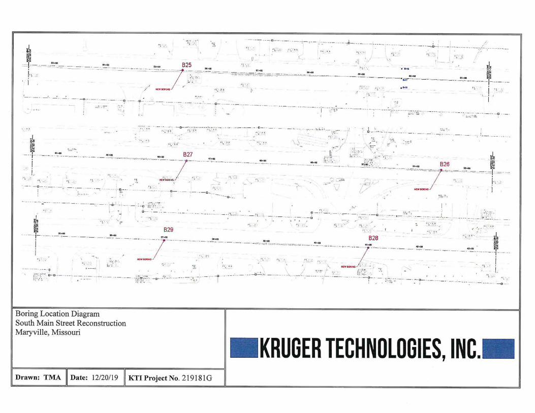
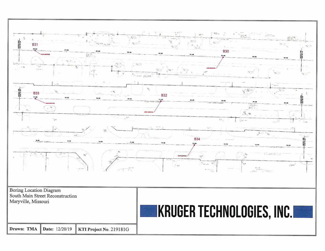
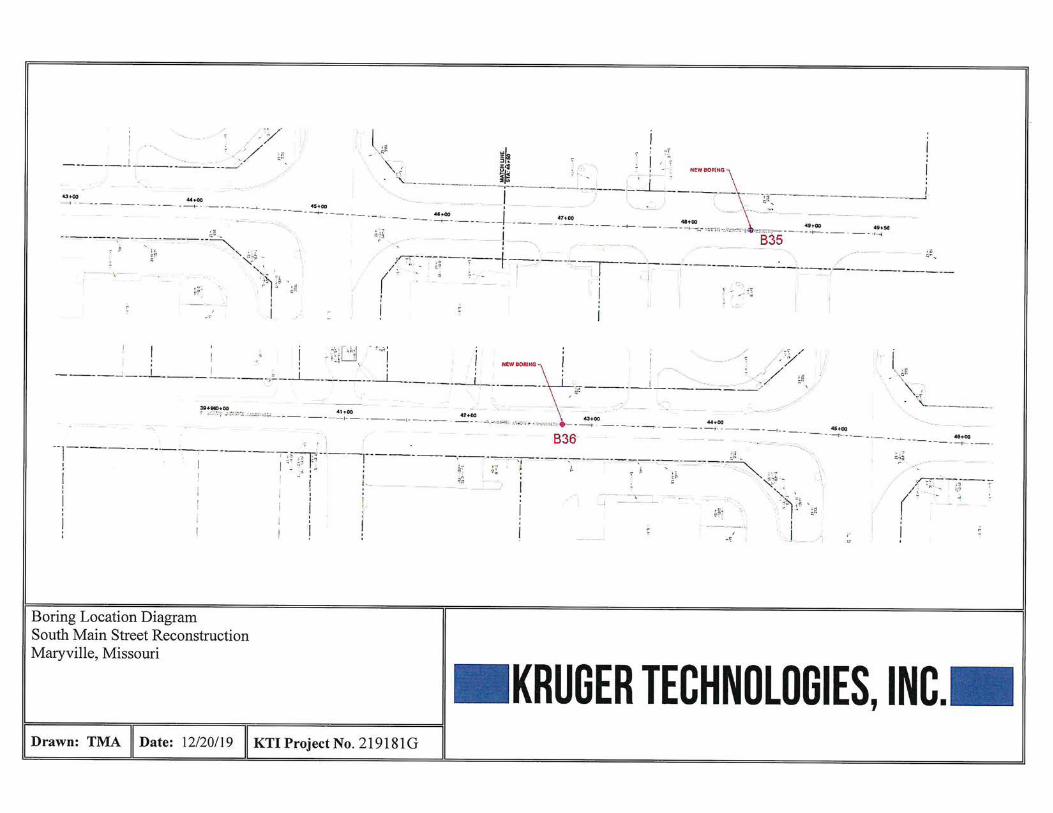
A total of 12 additional borings were completed on December 6, 2019 along the center line of the
drive lane. The borings were selected by the client and field located by Kruger Technologies using
site layout plans provided by the client. The boring locations are shown on the attached Boring
Location Diagram. Depths indicated on the boring logs are referenced from the ground surface
at the time of the exploration.
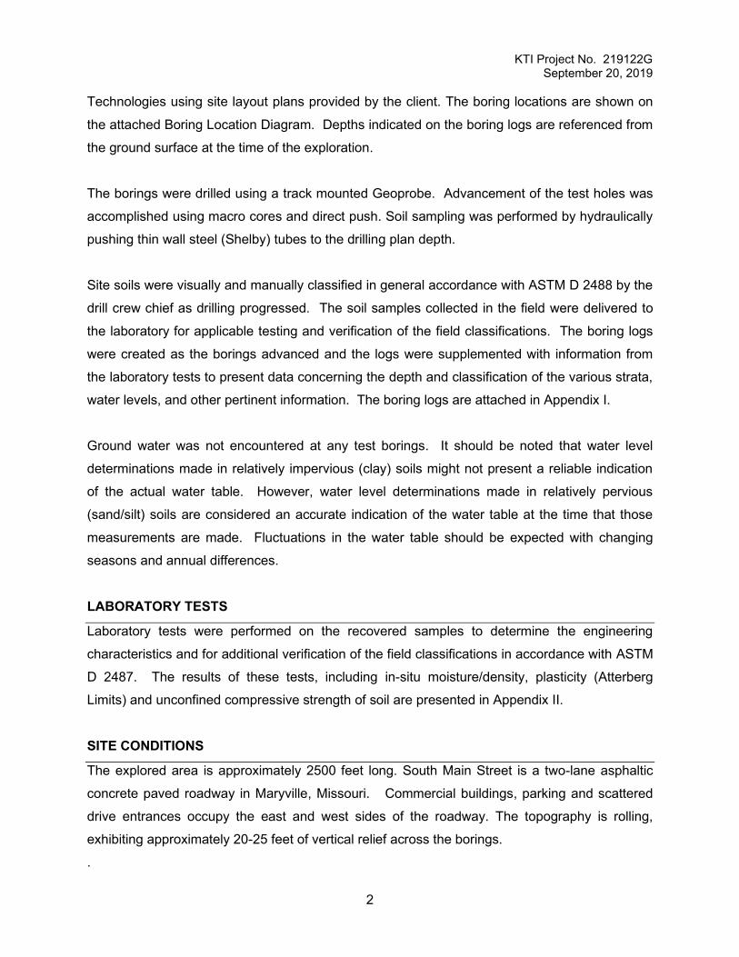
KTI Project No. 219181G December 27, 2019
2
The borings were drilled using a track mounted Geoprobe. Advancement of the test holes was
accomplished using macro cores and direct push. Soil sampling was performed by hydraulically
pushing thin wall steel (Shelby) tubes to the drilling plan depth.
Site soils were visually and manually classified in general accordance with ASTM D 2488 by the
drill crew chief as drilling progressed. The soil samples collected in the field were delivered to the
laboratory for applicable testing and verification of the field classifications. The boring logs were
created as the borings were advanced and the logs were supplemented with information from the
laboratory tests to present data concerning the depth and classification of the various strata, water
levels, and other pertinent information. The boring logs are attached in Appendix I.
Ground water was not encountered at any test borings. It should be noted that water level
determinations made in relatively impervious (clay) soils might not present a reliable indication of
the actual water table. However, water level determinations made in relatively pervious (sand/silt)
soils are considered an accurate indication of the water table at the time that those measurements
are made. Fluctuations in the water table should be expected with changing seasons and annual
differences.
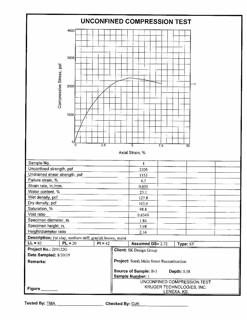
LABORATORY TESTS
Laboratory tests were performed on the recovered samples to determine the engineering
characteristics and for additional verification of the field classifications in accordance with ASTM
D 2487. The results of these tests, including in-situ moisture/density, plasticity (Atterberg Limits)
and unconfined compressive strength of soil are presented in Appendix II.
SITE CONDITIONS
The explored areas are South Main Street and the intersection at South Avenue, a two-lane
asphaltic concrete paved roadway in Maryville, Missouri. Commercial buildings, parking and
scattered drive entrances occupy the east and west sides of the roadway.
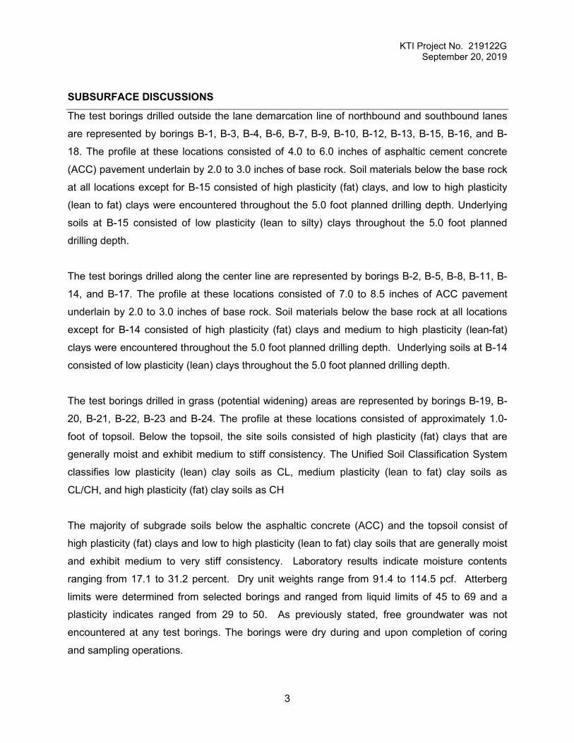
SUBSURFACE DISCUSSIONS
The test borings drilled at the center line of South Main Street are represented by borings B-25,
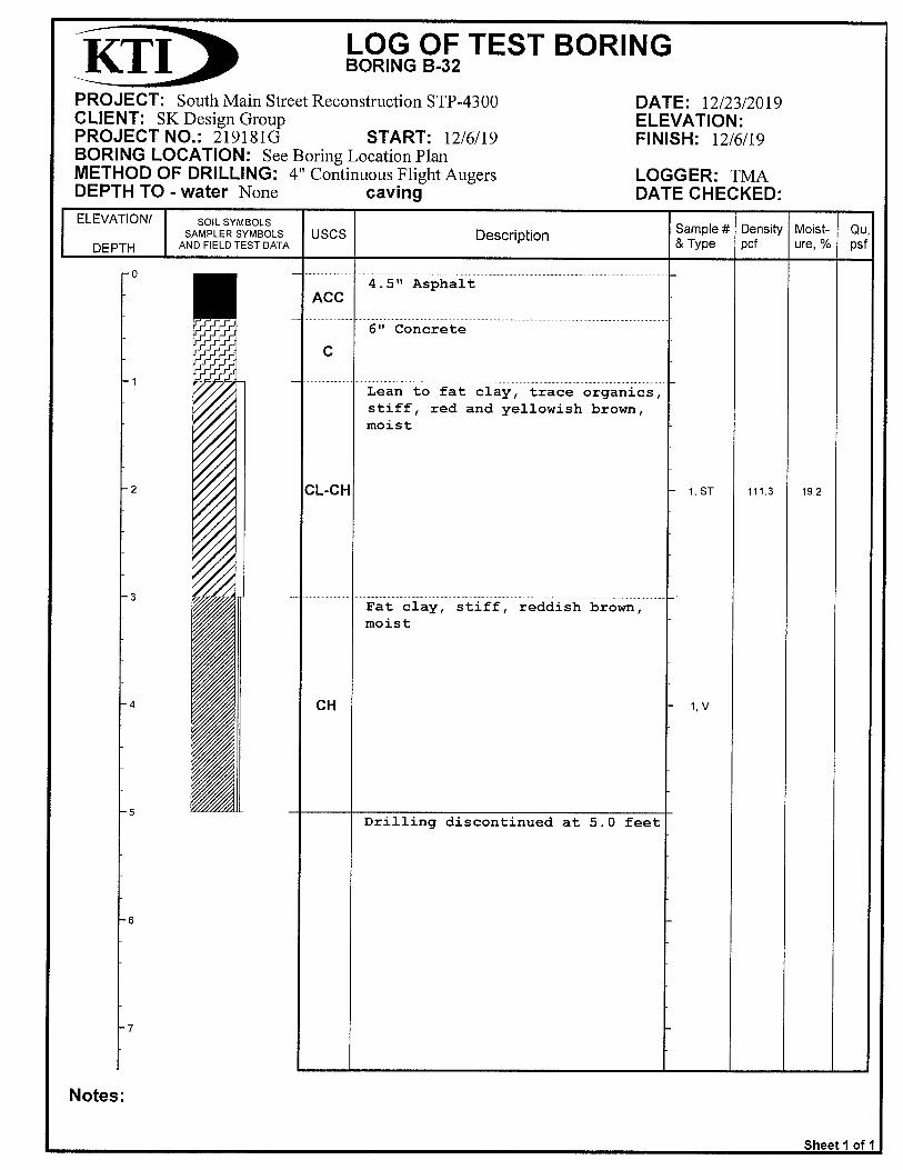
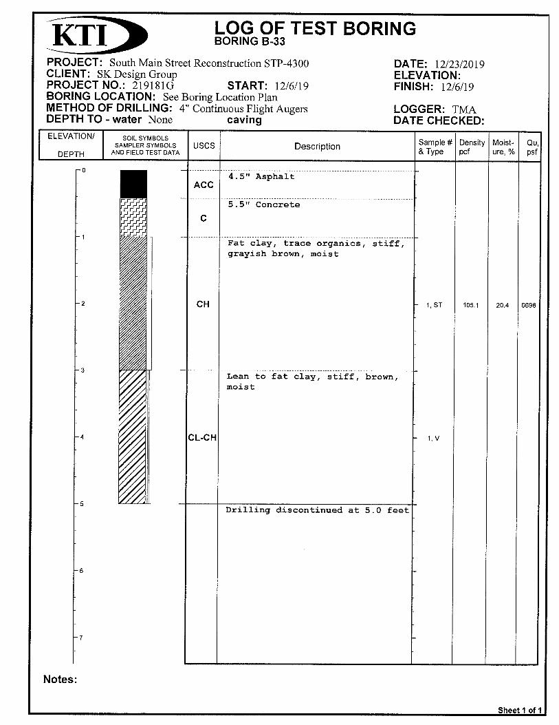
B-26, B-27, B-28, B-29, B-30, B-31, B-32, B-33 and B-34. The profile at these locations consisted
of 4.5 to 6.2 inches of asphaltic cement concrete (ACC) pavement underlain by 5.0 to 7.8 inches
KTI Project No. 219181G December 27, 2019
3
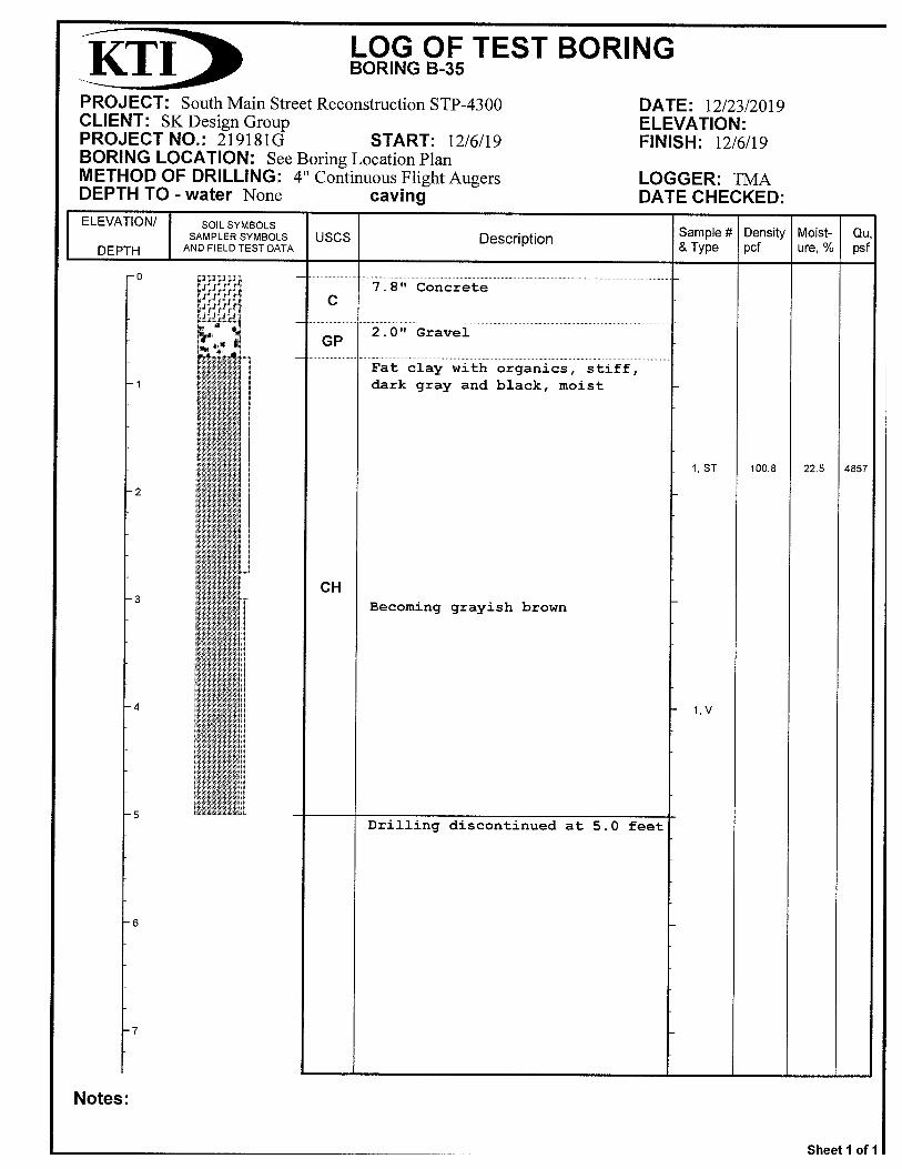
of concrete pavement. The test borings drilled at the center line of East South Avenue is
represented by B-35 and at this location the profile consists 7.8 inches of concrete underlain by
2 inches of poorly graded aggregate. The test boring drilled at the center line of West South
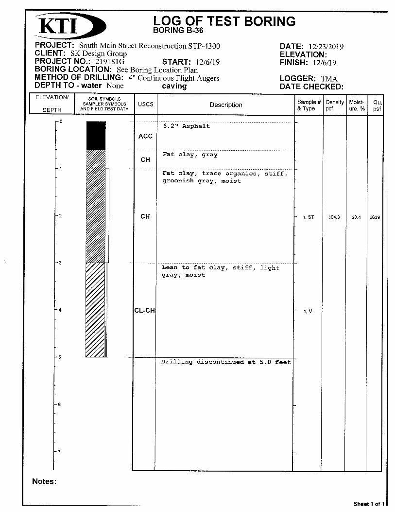
Avenue is represented by boring B-36 and at this location the profile consisted of 6.2 inches of
asphaltic cement concrete underlain by 2.0 inches of poorly graded aggregate. Soil materials
below the concrete and or asphalt at all locations except for B-27 consisted of high plasticity (CH)
clays, and low to high plasticity (CL-CH) clays were encountered throughout the 5.0-foot planned
drilling depth. Underlying soils at B-27 consisted of low plasticity lean (CL) clays up to 3.0 feet
below existing ground and underlain by fat clays (CH) throughout the 5.0-foot planned drilling
depth.
The majority of subgrade soils below the concrete and or asphalt pavement consist of high
plasticity (CH) clays and low to high plasticity (CL-CH) clay soils that are generally moist and
exhibit medium to very stiff consistency. Laboratory results indicate moisture contents ranging
from 16.9 to 20.4 percent. Dry unit weights range from 95.5 to 111.3 pcf. Atterberg limits were
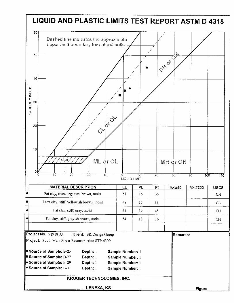
determined from selected borings and ranged from liquid limits of 48 to 64 and a plasticity
indicates ranged from 33 to 45. As previously stated, free groundwater was not encountered at
any test borings. The borings were dry during and upon completion of coring and sampling
operations.
Table 1 Asphalt and Concrete Pavement Thickness
Boring ID Asphalt Thickness (in) Concrete Thickness (in)
B-25 5.0 6.0
B-26 5.5 6.5
B-27 4.5 5.5
B-28 4.5 6.5
B-29 5.0 6.0
B-30 4.5 6.0
B-31 4.5 5.0
B-32 4.5 6.0
B-33 4.5 5.5
B-34 5.0 5.5
B-35 - 7.8
B-36 6.2 -
KTI Project No. 219181G December 27, 2019
4
DESIGN CRITERIA AND RECOMMENDATIONS
Laboratory test results of the recovered samples showed the following characteristics that were
used as criteria for determining the recommendations for bearing values and design data:
Natural Dry Density …………………………………………….…95.5 to 111.3 pcf
Natural Moisture Content ………………………………………...16.9 to 20.4%
Liquid Limit………………………………………………………….48 to 64
Plastic Limit………………………………………………………... 33 to 45
Unconfined Compressive Strength of soil …………………...… 3,132 to 6,698 psf
Site Preparation and Engineered Fill
Areas to receive fill should be stripped of vegetation, topsoil, and any other deleterious materials.
Any isolated areas of soft or deleterious materials encountered at subgrade elevation should be
removed and replaced with engineered fill. The moisture content of the subgrade soils should be
appropriate to achieve the required compaction.
Trucks and other heavy construction vehicles should be restricted as much as possible from
trafficking on the finished subgrade in the pavement to prevent unnecessary disturbances of
subgrade soils. Excessive rutting or pumping of the subgrade could occur from construction
traffic, particularly during periods of wet weather. If such disturbed areas develop, the subgrade
may have to be excavated and replaced with properly compacted fill.
Supplemental engineered fill should be placed in uniform horizontal lifts, with loose thicknesses
not exceeding 8 inches. The thickness must be appropriate for the method of compaction and the
type of equipment used. The geotechnical engineer should approve any off-site material
proposed for use as fill. Engineered fill should be compacted to a minimum of 95 percent of
maximum density as determined by ASTM D698 (standard Proctor test) at moisture content
between -2 to +2 percent from optimum moisture content for low plasticity clays. Most of the site
soils encountered during the exploration are not suitable for reuse as engineered fill below the
pavement.
The fill should be benched in any sloped areas greater than one vertical to five horizontal in order
to maintain relatively horizontal lifts. The benching should be placed at not less than 12-inch rises
over those areas where it is required as the work is brought up in layers.
KTI Project No. 219181G December 27, 2019
5
Lateral Earth Pressure
The following K values, based on the clay soils encountered on the site, and crushed rock backfill
obtained from off-site source, may be used for the determination of lateral soil resistance for
retaining structures or buried walls. These values do not take into account surcharges caused by
construction equipment or spoil piles placed adjacent to retaining structures.
Compacted High Plasticity Clay Backfill
Angle of internal friction () = 20° (estimated)
Ka = 0.49 Kp = 2.05 Ko = 0.66
Wet density of in place soil, average () = 125.0 pcf
Compacted Low Plasticity Clay Backfill
Angle of internal friction () = 26° (estimated)
Ka = 0.39 Kp = 2.56 Ko = 0.56
Wet density of in place soil, average () = 125.0 pcf
Crushed Rock Backfill
Angle of internal friction () = 35° (estimated)
Ka = 0.27 Kp = 3.70 Ko = 0.42
Wet density of backfill () = 135.0 pcf
Pavement Subgrade Preparation
Pavement subgrades should be prepared in accordance with the recommendations presented in
the SITE PREPARATION and ENGINEERED FILL section of this report. Construction
scheduling, involving paving and grading by separate contractors, typically results in a time lapse
between the end of grading operations and the commencement of paving. Disturbance,
desiccation, and/or wetting of the subgrade between grading and paving can result in deterioration
of the previously completed subgrade. A non-uniform subgrade can result in poor pavement
performance and local failures soon after pavements are constructed.
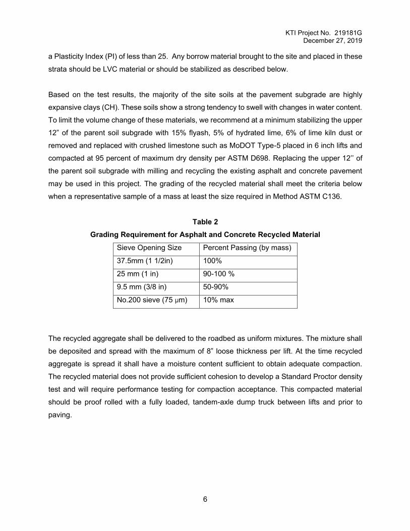
We recommend that the upper 12’’ of subgrade soils consist of a low volume change (LVC)
material. Acceptable LVC material is any soil type that has a Liquid Limit (LL) of less than 45 and
KTI Project No. 219181G December 27, 2019
6
a Plasticity Index (PI) of less than 25. Any borrow material brought to the site and placed in these
strata should be LVC material or should be stabilized as described below.
Based on the test results, the majority of the site soils at the pavement subgrade are highly
expansive clays (CH). These soils show a strong tendency to swell with changes in water content.
To limit the volume change of these materials, we recommend at a minimum stabilizing the upper
12” of the parent soil subgrade with 15% flyash, 5% of hydrated lime, 6% of lime kiln dust or
removed and replaced with crushed limestone such as MoDOT Type-5 placed in 6 inch lifts and
compacted at 95 percent of maximum dry density per ASTM D698. Replacing the upper 12’’ of
the parent soil subgrade with milling and recycling the existing asphalt and concrete pavement
may be used in this project. The grading of the recycled material shall meet the criteria below
when a representative sample of a mass at least the size required in Method ASTM C136.
Table 2 Grading Requirement for Asphalt and Concrete Recycled Material
Sieve Opening Size Percent Passing (by mass)
37.5mm (1 1/2in) 100%
25 mm (1 in) 90-100 %
9.5 mm (3/8 in) 50-90%
No.200 sieve (75 μm) 10% max
The recycled aggregate shall be delivered to the roadbed as uniform mixtures. The mixture shall
be deposited and spread with the maximum of 8” loose thickness per lift. At the time recycled
aggregate is spread it shall have a moisture content sufficient to obtain adequate compaction.
The recycled material does not provide sufficient cohesion to develop a Standard Proctor density
test and will require performance testing for compaction acceptance. This compacted material
should be proof rolled with a fully loaded, tandem-axle dump truck between lifts and prior to
paving.
KTI Project No. 219181G December 27, 2019
7
REMARKS
It is recommended that the geotechnical engineer be retained to review the plans and
specifications for the project so that an evaluation and comments can be provided regarding the
proper incorporation of information from this geotechnical report into the final construction
documents. We further recommend that the geotechnical engineer be retained during
construction phases for earthwork and foundations to provide observation and testing to aid in
determining that design intent has been accomplished.
The findings in this report are based on data acquired to date and are assumed to be
representative of conditions at locations between borings. Due to the fact that the area at the
borings is very small relative to the overall site, and for other reasons, we make no statement
warranting the conditions below our borings or at other locations throughout the site. In addition,
we do not warrant that the general strata logged at the borings are necessarily typical of the
remaining areas of the site.
Reports shall not be reproduced, except in full, without written approval of KTI. Information in this
report applies only to the referenced project in its present configuration and location and shall not
be used for any other project or location.

KTI Project No. 219181G December 27, 2019
8
BORING LOCATION DIAGRAM
KTI Project No. 219181G December 27, 2019
12
APPENDIX I
Boring Logs


KTI Project No. 219181G December 27, 2019
25
APPENDIX II
Laboratory Results

KTI Project No. 219181G December 27, 2019
26
SUMMARY OF LABORATORY TEST RESULTS UNDISTURBED SAMPLE
Boring Depth (Ft)
Sample No./Type
Natural
Moisture %
Natural Dry Density (pcf)
Unconfined Compressive Strength (psf)
Atterberg Limits Soil Type
Liquid Limit
%
Plasticity Index0
% B-25 1.0-3.0 ST-1 17.0 106.9 51 35 CH B-26 1.0-3.0 ST-1 16.9 101.8 B-27 1.0-3.0 ST-1 18.8 111.0 6666 48 33 CL B-28 1.0-3.0 ST-1 17.7 105.3 B-29 1.0-3.0 ST-1 22.9 101.1 3899 64 45 CH B-30 1.0-3.0 ST-1 23.9 95.6 B-31 1.0-3.0 ST-1 26.7 95.5 3132 54 36 CH B-32 1.0-3.0 ST-1 19.2 111.3 B-33 1.0-3.0 ST-1 20.4 105.1 6698 52 35 CH B-34 1.0-3.0 ST-1 17.2 110.2 B-35 1.0-3.0 ST-1 22.5 100.8 4857 59 39 CH B-36 1.0-3.0 ST-1 20.4 104.3 6639


KTI Project No. 219181G December 27, 2019
35
GLOSSARY OF GEOTECHNICAL TERMS
ALLUVIUM Sediments deposited by streams, including riverbeds and floodplains. ARGILLACEOUS Rocks composed of or having a notable portion of fine silt and/or clay
in their composition. ATTERBERG LIMITS Water contents, in percentage of dry weight of soil, that correspond to
the boundaries between the states of consistency, i.e. the boundary between the liquid and plastic states (liquid limit) and the boundary between the plastic and solid states (plastic limit).
BEDROCK-IN-PLACE Continuous rock mass which essentially has not moved from its
original depositional position. CALCAREOUS Containing calcium carbonate determined by effervescence when
tested with dilute hydrochloric acid. CHANNEL SANDSTONE Sandstone that has been deposited in a streambed or other channel
eroded into the underlying beds. COLLUVIAL Rock debris of various sizes loose from in-place bedrock mass, often
shifted down gradient in conjunction with soil. CROSS-BEDDING Stratification which is inclined to the original horizontal surface upon
which the sediment accumulated. FISSILE BEDDING Term applied to bedding which consists of laminae less than 2
millimeters in thickness. FORMATION A distinctive body of rock that serves as a convenient unit for study
and mapping. FOSSIL DETRITUS The accumulation of broken, fragmented fossil debris. FOSSILIFEROUS Containing organic remains. GLACIAL ERRATIC A transported rock fragment different from the bedrock on which it lies,
either free or as part of a sediment. GLACIAL TILL Nonsorted, nonstratified sediment carried or deposited by a glacier. GLACIOFLUVIAL Primarily deposited by streams from glaciers. GROUP A lithostratigraphic unit consisting of two or more formations. JOINT A fracture in a rock along which no appreciable displacement has
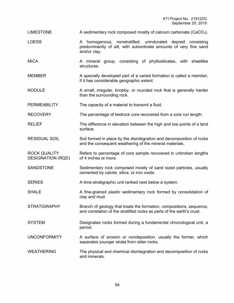
occurred. LIMESTONE A sedimentary rock composed mostly of calcium carbonate (CaCO3).

KTI Project No. 219181G December 27, 2019
36
LOESS A homogenous, nonstratified, unindurated deposit consisting
predominantly of silt, with subordinate amounts of very fine sand and/or clay.
MICA A mineral group, consisting of phyllosilicates, with sheetlike
structures. MEMBER A specially developed part of a varied formation is called a member, if
it has considerable geographic extent. NODULE A small, irregular, knobby, or rounded rock that is generally harder
than the surrounding rock. PERMEABILITY The capacity of a material to transmit a fluid. RECOVERY The percentage of bedrock core recovered from a core run length. RELIEF The difference in elevation between the high and low points of a land
surface. RESIDUAL SOIL Soil formed in place by the disintegration and decomposition of rocks
and the consequent weathering of the mineral materials. ROCK QUALITY DESIGNATION (RQD)
Refers to percentage of core sample recovered in unbroken lengths of 4 inches or more.
SANDSTONE Sedimentary rock composed mostly of sand sized particles, usually
cemented by calcite, silica, or iron oxide. SERIES A time-stratigraphic unit ranked next below a system. SHALE A fine-grained plastic sedimentary rock formed by consolidation of
clay and mud. STRATIGRAPHY Branch of geology that treats the formation, compositions, sequence,
and correlation of the stratified rocks as parts of the earth's crust. SYSTEM Designates rocks formed during a fundamental chronological unit, a
period. UNCONFORMITY A surface of erosion or nondeposition, usually the former, which
separates younger strata from older rocks. WEATHERING The physical and chemical disintegration and decomposition of rocks
and minerals.
KTI Project No. 219181G December 27, 2019
37
General Notes
Laboratory Test Symbols
Symbol Definition LL Liquid Limit (ASTM D4318) PL Plastic Limit (ASTM D4318) PI Plasticity Index (LL minus PL) Qu Unconfined Compressive Strength, Pounds per Square Foot (psf) Qp Pocket Penetrometer Reading, Tons per Square Foot (TSF)
RQD Rock Quality Designation % (Sum of rock core pieces >4 inches/length of core run)
Common Soil Classification Symbols
Descriptive Terminology
Cohesionless Soils Cohesive Soils
Relative Proportions and Sizes
Clay Symbol Soil Type
CL Low plasticity clay CL-ML Low plasticity clay and silt CL/CH Medium plasticity clay
CH High plasticity clay
Silt Symbol Soil Type
ML Low plasticity silt MH High plasticity silt
Sand Symbol Soil Type
SW Well graded sand SP Poorly graded sand SM Silty sand SC Clayey sand
Gravel Symbol Soil Type
GW Well graded gravel GP Poorly graded gravel GM Silty gravel GC Clayey gravel
Relative Density Term “N” Value Very Loose 0 - 4
Loose 5 - 9 Medium Dense 10 - 29
Dense 30 – 49 Very Dense 50 or more
Consistency Term “N” Value Very soft 0 – 2
Soft 3 – 4 Medium 5 – 8
Stiff 9 – 15 Very Stiff 16 - 30
Hard > 30
Term Range Trace < 5% A Little 5 – 15% Some 15 – 30% With 30 – 50%
Material Size Boulder > 12” Cobble 3” – 12” Gravel 4.75 - 76.2 mm Sand 0.075 – 4.75 mm
Silt and Clay < 0.075 mm
REPORT OF GEOTECHNICAL EXPLORATION SOUTH MAIN STREET RECONSTRUCTION
MARYVILLE, MISSOURI
Presented to:
Mr. John D. Chamberlin, P.E. SK Design Group, Inc.
Prepared by:
Otto J. Kruger, Jr., P.E. Tadele M. Akalu
Kruger Technologies, Inc. Lenexa, Kansas
KTI Project No. 219122G September 20, 2019
KTI Project No. 219122G September 20, 2019
i
TABLE OF CONTENTS AUTHORIZATION ...................................................................................................................... 1
PURPOSE AND SCOPE ........................................................................................................... 1
PROJECT DESCRIPTION ......................................................................................................... 1
FIELD EXPLORATION PROCEDURES..................................................................................... 1
LABORATORY TESTS .............................................................................................................. 2
SITE CONDITIONS ................................................................................................................... 2
SUBSURFACE DISCUSSIONS ................................................................................................. 3
DESIGN CRITERIA AND RECOMMENDATIONS ..................................................................... 4
Site Preparation and Engineered Fill .............................................................................. 4
Lateral Earth Pressure…………………………………………………………………………..5
Pavement Subgrade Preparation .................................................................................... 5
REMARKS ................................................................................................................................. 7
BORING LOCATION DIAGRAM ................................................................................................ 8
APPENDIX I ..............................................................................................................................11
Boring Logs ...................................................................................................................12
APPENDIX II .............................................................................................................................36
Summary of Pavement Profile .......................................................................................37
APPENDIX III…………………………………………………………………………………………. 38
Laboratory Results………………………………………………………………………….. 39
GLOSSARY OF GEOTECHNICAL TERMS ..............................................................................53
KTI Project No. 219122G September 20, 2019
1
REPORT OF GEOTECHNICAL EXPLORATION
SOUTH MAIN STREET RECONSTRUCTION MARYVILLE, MISSOURI
AUTHORIZATION
The following table presents the authorization documentation history for the work performed and
presented in this report by Kruger Technologies, Inc.
Project: South Main Street Reconstruction-Maryville, Missouri
Document: Date: Requested/Provided: Request for Proposal 6-7-19 Toby Williams – SK Design Group, Inc.
KTI Proposal 19GT079 6-26-19 Dylan Kruger – Kruger Technologies, Inc.
Notice to Proceed 8-7-19 John Chamberlin – SK Design Group, Inc.
PURPOSE AND SCOPE
The purpose of this investigation was to explore the surface and subsurface conditions present
within the South Main Street site and provide recommendations regarding the following:
• Site Preparation and Engineered Fill
• Subgrade Recommendations
PROJECT DESCRIPTION
We understand that the project consists of the design and reconstruction of the existing South
Main Street located in Maryville, Missouri. This is the second phase of this project extending
from just south of 285th Street to approximately 2,500 feet north. Proposed improvements
include widening, full depth pavement replacement, driveway reconfiguration and traffic control.
It appears that 5 to 8 feet of fill could be required in the widening areas, depending on the final
alignment and cross section of the proposed reconstruction.
FIELD EXPLORATION PROCEDURES
A total of 24 borings were completed on August 30, 2019, including twelve (12) test borings
drilled outside the lane demarcation line on the asphalt shoulder area of northbound and south
bound lanes, six (6) test borings drilled along the center line of the drive lane and six (6) test
borings drilled in grass areas at an approximate 6’ offset from the asphalt roadway edge of both
north and southbound lanes. The borings were selected by the client and field located by Kruger
KTI Project No. 219122G September 20, 2019
2
Technologies using site layout plans provided by the client. The boring locations are shown on
the attached Boring Location Diagram. Depths indicated on the boring logs are referenced from
the ground surface at the time of the exploration.
The borings were drilled using a track mounted Geoprobe. Advancement of the test holes was
accomplished using macro cores and direct push. Soil sampling was performed by hydraulically
pushing thin wall steel (Shelby) tubes to the drilling plan depth.
Site soils were visually and manually classified in general accordance with ASTM D 2488 by the
drill crew chief as drilling progressed. The soil samples collected in the field were delivered to
the laboratory for applicable testing and verification of the field classifications. The boring logs
were created as the borings advanced and the logs were supplemented with information from
the laboratory tests to present data concerning the depth and classification of the various strata,
water levels, and other pertinent information. The boring logs are attached in Appendix I.
Ground water was not encountered at any test borings. It should be noted that water level
determinations made in relatively impervious (clay) soils might not present a reliable indication
of the actual water table. However, water level determinations made in relatively pervious
(sand/silt) soils are considered an accurate indication of the water table at the time that those
measurements are made. Fluctuations in the water table should be expected with changing
seasons and annual differences.
LABORATORY TESTS
Laboratory tests were performed on the recovered samples to determine the engineering
characteristics and for additional verification of the field classifications in accordance with ASTM
D 2487. The results of these tests, including in-situ moisture/density, plasticity (Atterberg
Limits) and unconfined compressive strength of soil are presented in Appendix II.
SITE CONDITIONS
The explored area is approximately 2500 feet long. South Main Street is a two-lane asphaltic
concrete paved roadway in Maryville, Missouri. Commercial buildings, parking and scattered
drive entrances occupy the east and west sides of the roadway. The topography is rolling,
exhibiting approximately 20-25 feet of vertical relief across the borings.
.
KTI Project No. 219122G September 20, 2019
3
SUBSURFACE DISCUSSIONS
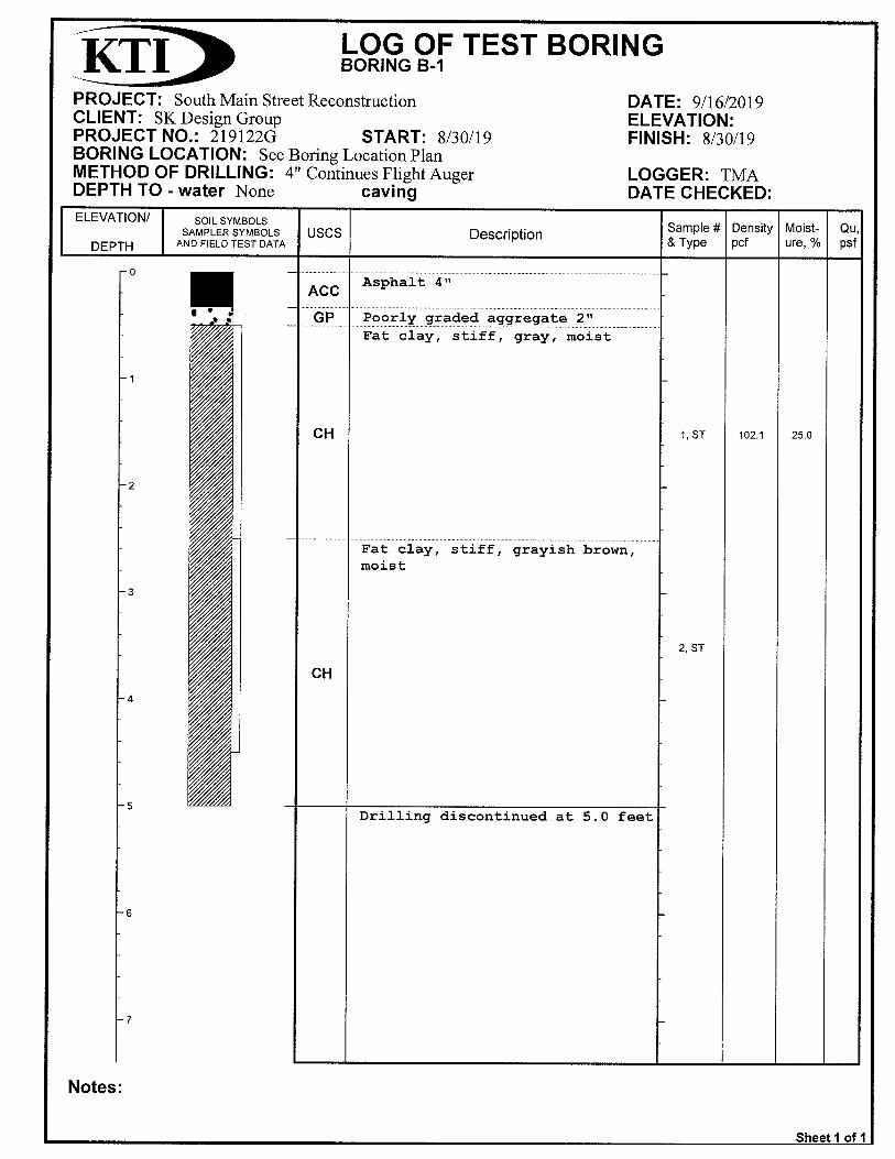
The test borings drilled outside the lane demarcation line of northbound and southbound lanes
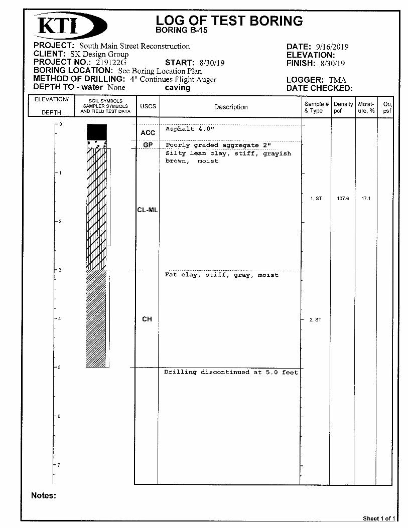
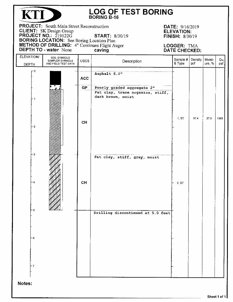
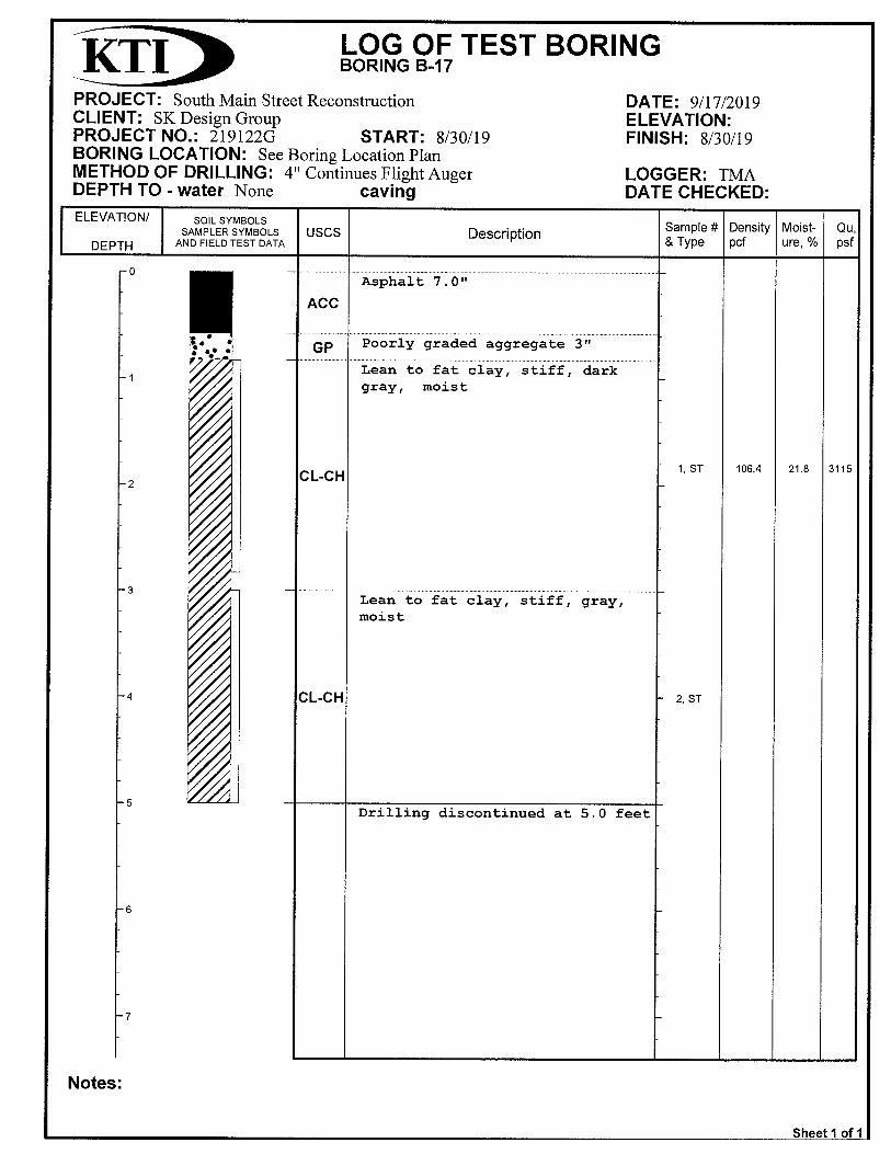
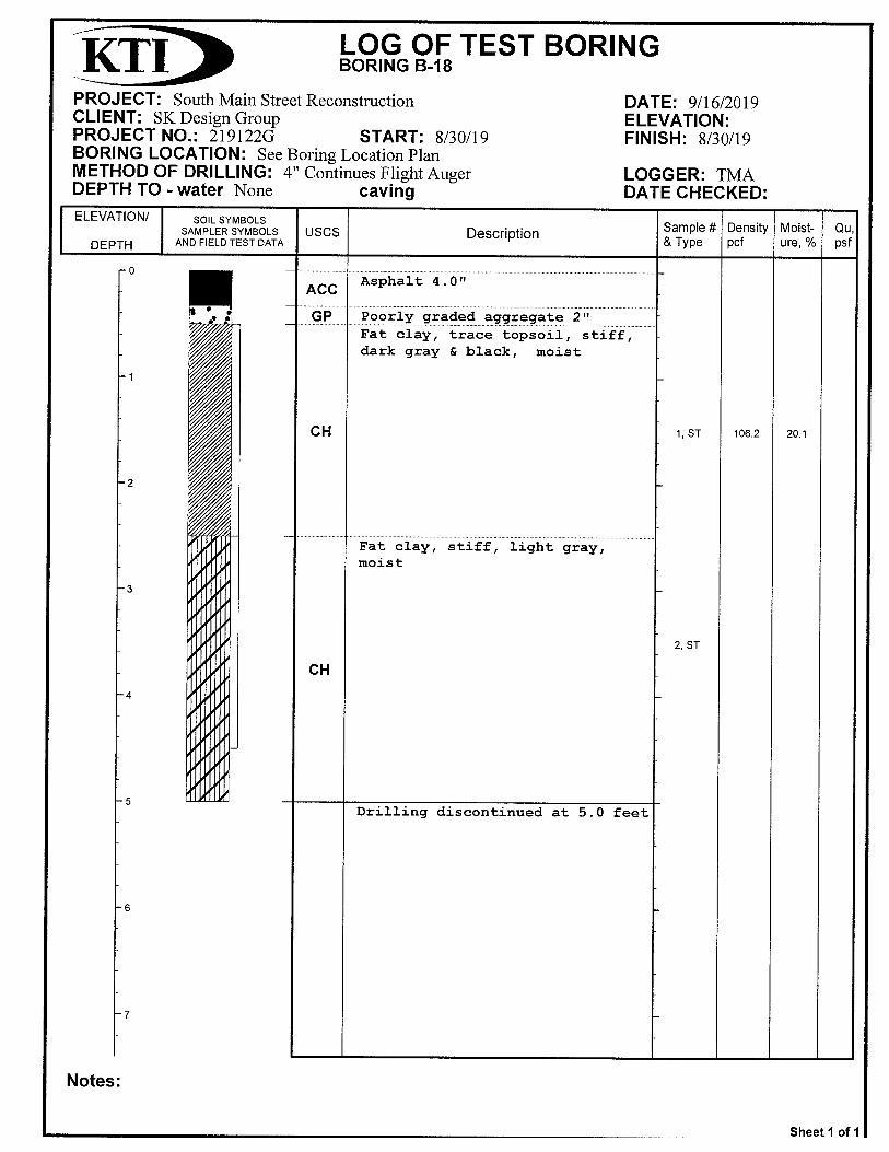
are represented by borings B-1, B-3, B-4, B-6, B-7, B-9, B-10, B-12, B-13, B-15, B-16, and B-
18. The profile at these locations consisted of 4.0 to 6.0 inches of asphaltic cement concrete
(ACC) pavement underlain by 2.0 to 3.0 inches of base rock. Soil materials below the base rock
at all locations except for B-15 consisted of high plasticity (fat) clays, and low to high plasticity
(lean to fat) clays were encountered throughout the 5.0 foot planned drilling depth. Underlying
soils at B-15 consisted of low plasticity (lean to silty) clays throughout the 5.0 foot planned
drilling depth.
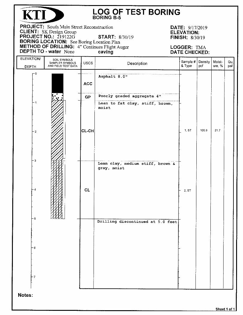
The test borings drilled along the center line are represented by borings B-2, B-5, B-8, B-11, B-
14, and B-17. The profile at these locations consisted of 7.0 to 8.5 inches of ACC pavement
underlain by 2.0 to 3.0 inches of base rock. Soil materials below the base rock at all locations
except for B-14 consisted of high plasticity (fat) clays and medium to high plasticity (lean-fat)
clays were encountered throughout the 5.0 foot planned drilling depth. Underlying soils at B-14
consisted of low plasticity (lean) clays throughout the 5.0 foot planned drilling depth.
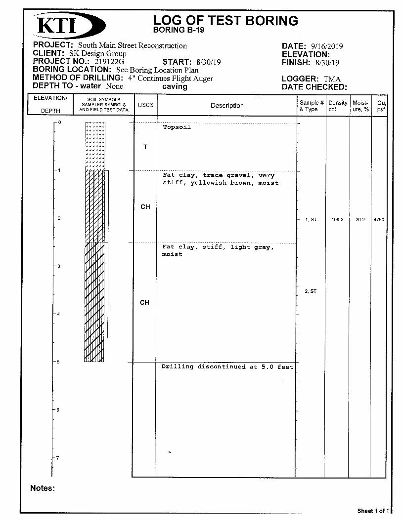
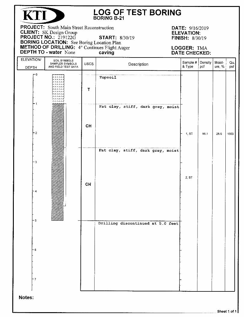
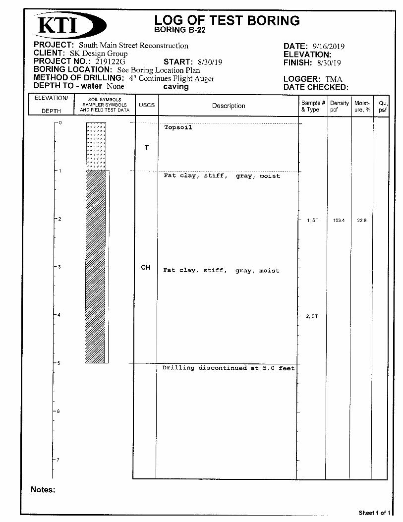
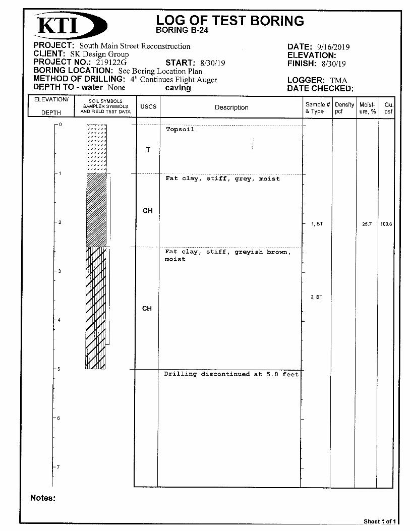
The test borings drilled in grass (potential widening) areas are represented by borings B-19, B-
20, B-21, B-22, B-23 and B-24. The profile at these locations consisted of approximately 1.0-
foot of topsoil. Below the topsoil, the site soils consisted of high plasticity (fat) clays that are
generally moist and exhibit medium to stiff consistency. The Unified Soil Classification System
classifies low plasticity (lean) clay soils as CL, medium plasticity (lean to fat) clay soils as
CL/CH, and high plasticity (fat) clay soils as CH
The majority of subgrade soils below the asphaltic concrete (ACC) and the topsoil consist of
high plasticity (fat) clays and low to high plasticity (lean to fat) clay soils that are generally moist
and exhibit medium to very stiff consistency. Laboratory results indicate moisture contents
ranging from 17.1 to 31.2 percent. Dry unit weights range from 91.4 to 114.5 pcf. Atterberg
limits were determined from selected borings and ranged from liquid limits of 45 to 69 and a
plasticity indicates ranged from 29 to 50. As previously stated, free groundwater was not
encountered at any test borings. The borings were dry during and upon completion of coring
and sampling operations.
KTI Project No. 219122G September 20, 2019
4
DESIGN CRITERIA AND RECOMMENDATIONS
Laboratory test results of the recovered samples showed the following characteristics that were
used as criteria for determining the recommendations for bearing values and design data:
Natural Dry Density …………………………………………….…91.4 to 114.5 pcf
Natural Moisture Content ………………………………………...17.1 to 31.2%
Liquid Limit………………………………………………………….45 to 69
Plastic Limit………………………………………………………... 29 to 50
Unconfined Compressive Strength of soil …………………...… 1,116 to 6,095 psf
Site Preparation and Engineered Fill
Areas to receive fill should be stripped of vegetation, topsoil, and any other deleterious
materials. Any isolated areas of soft or deleterious materials encountered at subgrade elevation
should be removed and replaced with engineered fill. The moisture content of the subgrade
soils should be appropriate to achieve the required compaction.
Trucks and other heavy construction vehicles should be restricted as much as possible from
trafficking on the finished subgrade in the pavement to prevent unnecessary disturbances of
subgrade soils. Excessive rutting or pumping of the subgrade could occur from construction
traffic, particularly during periods of wet weather. If such disturbed areas develop, the subgrade
may have to be excavated and replaced with properly compacted fill.
Supplemental engineered fill should be placed in uniform horizontal lifts, with loose thicknesses
not exceeding 8 inches. The thickness must be appropriate for the method of compaction and
the type of equipment used. The geotechnical engineer should approve any off-site material
proposed for use as fill. Engineered fill should be compacted to a minimum of 95 percent of
maximum density as determined by ASTM D698 (standard Proctor test) at moisture content
between -2 to +2 percent from optimum moisture content for low plasticity clays. Most of the
site soils encountered during the exploration are not suitable for reuse as engineered fill below
the pavement.
The fill should be benched in any sloped areas greater than one vertical to five horizontal in
order to maintain relatively horizontal lifts. The benching should be placed at not less than 12-
inch rises over those areas where it is required as the work is brought up in layers.
KTI Project No. 219122G September 20, 2019
5
LATERAL EARTH PRESSURE________________________________________________________
The following K values, based on the clay soils encountered on the site, and crushed rock
backfill obtained from off-site source, may be used for the determination of lateral soil resistance
for retaining structures or buried walls. These values do not take into account surcharges
caused by construction equipment or spoil piles placed adjacent to retaining structures.
Compacted High Plasticity Clay Backfill
Angle of internal friction () = 20° (estimated)
Ka = 0.49 Kp = 2.05 Ko = 0.66
Wet density of in place soil, average () = 125.0 pcf
Compacted Low Plasticity Clay Backfill
Angle of internal friction () = 26° (estimated)
Ka = 0.39 Kp = 2.56 Ko = 0.56
Wet density of in place soil, average () = 125.0 pcf
Crushed Rock Backfill
Angle of internal friction () = 35° (estimated)
Ka = 0.27 Kp = 3.70 Ko = 0.42
Wet density of backfill () = 135.0 pcf
Pavement Subgrade Preparation
Pavement subgrades should be prepared in accordance with the recommendations presented
in the SITE PREPARATION and ENGINEERED FILL section of this report. Construction
scheduling, involving paving and grading by separate contractors, typically results in a time
lapse between the end of grading operations and the commencement of paving. Disturbance,
desiccation, and/or wetting of the subgrade between grading and paving can result in
deterioration of the previously completed subgrade. A non-uniform subgrade can result in poor
pavement performance and local failures soon after pavements are constructed.
We recommend that the upper 12’ of subgrade soils consist of a low volume change (LVC)
material. Acceptable LVC material is any soil type that has a Liquid Limit (LL) of less than 45

KTI Project No. 219122G September 20, 2019
6
and a Plasticity Index (PI) of less than 25. Any borrow material brought to the site and placed in
this strata should be LVC material or should be stabilized as described below.
Based on the test results, the site soils at the pavement subgrade are highly expensive clays
(CH). These soils show a strong tendency to swell with changes in water content. To limit the
volume change of these materials, we recommend at a minimum stabilizing the upper 12” of the
parent soil subgrade with 15% flyash, 5% of hydrated lime, 6% of lime kiln dust or removed and
replaced with crushed limestone such as MoDOT Type-5 placed in 6 inches lifts and compacted
at 95 percent of maximum dry density per ASTM D698.
KTI Project No. 219122G September 20, 2019
7
REMARKS
It is recommended that the geotechnical engineer be retained to review the plans and
specifications for the project so that an evaluation and comments can be provided regarding the
proper incorporation of information from this geotechnical report into the final construction
documents. We further recommend that the geotechnical engineer be retained during
construction phases for earthwork and foundations to provide observation and testing to aid in
determining that design intent has been accomplished.
The findings in this report are based on data acquired to date and are assumed to be
representative of conditions at locations between borings. Due to the fact that the area at the
borings is very small relative to the overall site, and for other reasons, we make no statement
warranting the conditions below our borings or at other locations throughout the site. In
addition, we do not warrant that the general strata logged at the borings are necessarily typical
of the remaining areas of the site.
Reports shall not be reproduced, except in full, without written approval of KTI. Information in
this report applies only to the referenced project in its present configuration and location and
shall not be used for any other project or location.
KTI Project No. 219122G September 20, 2019
8
BORING LOCATION DIAGRAM
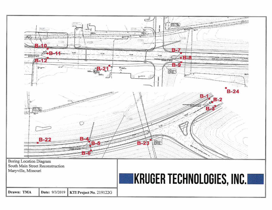

KTI Project No. 219122G September 20, 2019
11
APPENDIX I
Boring Logs


KTI Project No. 219122G September 20, 2019
36
APPENDIX II
Summary of Pavement Profile
KTI Project No. 219122G September 20, 2019
37
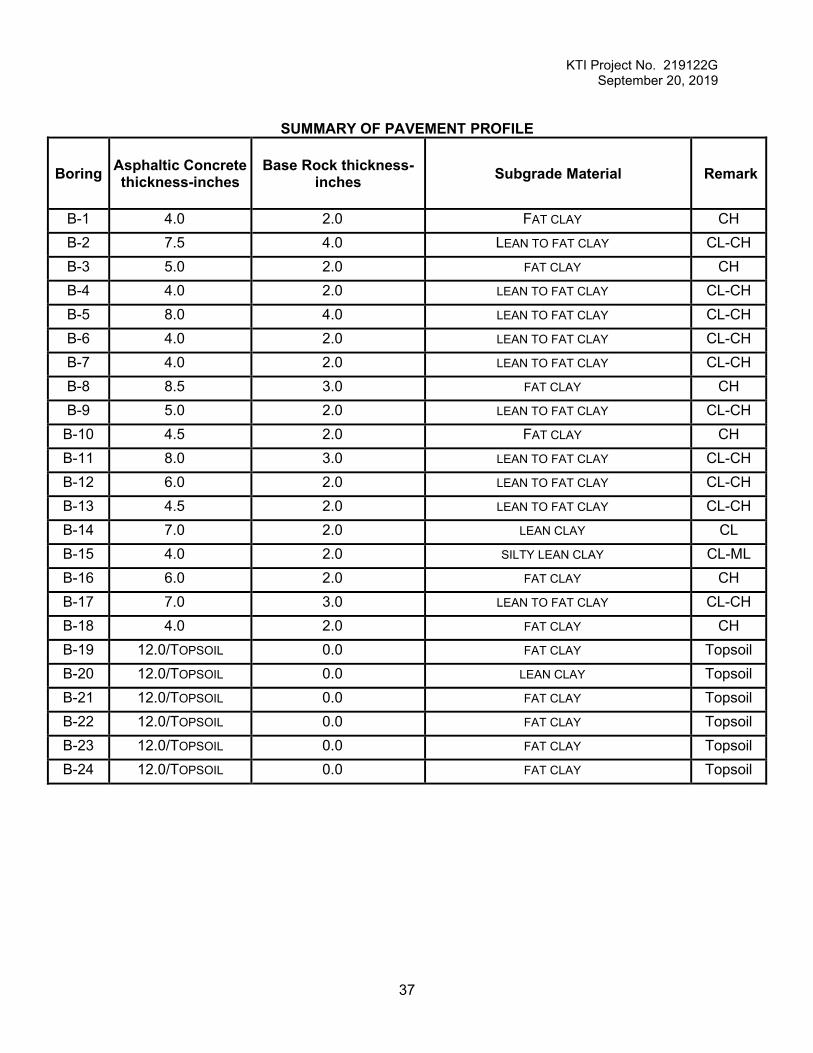
SUMMARY OF PAVEMENT PROFILE
Boring Asphaltic Concrete thickness-inches
Base Rock thickness-inches Subgrade Material Remark
B-1 4.0
ST-1
2.0
102.1
FAT CLAY CH B-2 7.5
1.0-3.0
4.0
91.4
LEAN TO FAT CLAY CL-CH B-3 5.0
1.0-3.0
2.0 FAT CLAY CH B-4 4.0
1.0-3.0
2.0 LEAN TO FAT CLAY CL-CH B-5 8.0
1.0-3.0
4.0 LEAN TO FAT CLAY CL-CH B-6 4.0
1.0-3.0
2.0 LEAN TO FAT CLAY CL-CH B-7 4.0
1.0-3.0
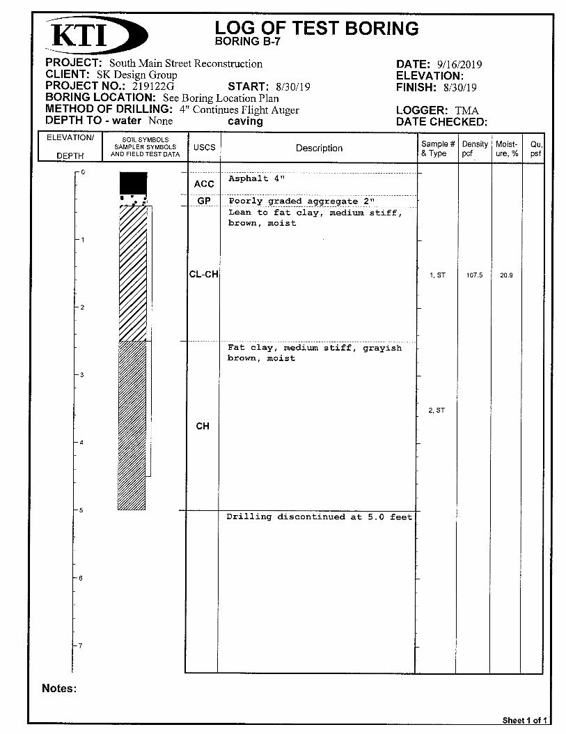
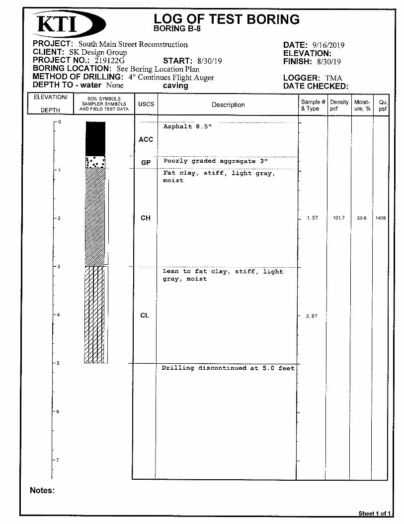
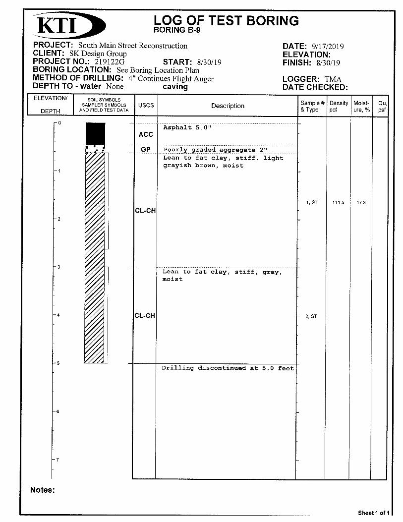
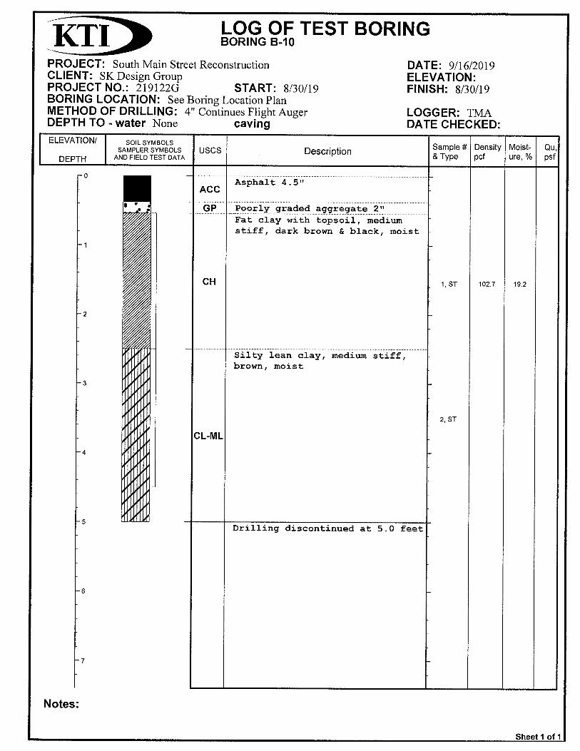
2.0 LEAN TO FAT CLAY CL-CH B-8 8.5 3.0 FAT CLAY CH B-9 5.0
1.0-3.0
2.0 LEAN TO FAT CLAY CL-CH B-10 4.5 2.0 FAT CLAY CH B-11 8.0
1.0-3.0
3.0 LEAN TO FAT CLAY CL-CH B-12 6.0
1.0-3.0
2.0 LEAN TO FAT CLAY CL-CH B-13 4.5
1.0-3.0
2.0 LEAN TO FAT CLAY CL-CH B-14 7.0
1.0-3.0
2.0 LEAN CLAY CL B-15 4.0
1.0-3.0
2.0 SILTY LEAN CLAY CL-ML B-16 6.0
1.0-3.0
2.0 FAT CLAY CH B-17 7.0 3.0 LEAN TO FAT CLAY CL-CH B-18 4.0
1.0-3.0
2.0 FAT CLAY CH B-19 12.0/TOPSOIL 0.0
109.3
FAT CLAY Topsoil B-20 12.0/TOPSOIL 0.0
1090.3
LEAN CLAY Topsoil B-21 12.0/TOPSOIL 0.0
109.3
FAT CLAY Topsoil B-22 12.0/TOPSOIL 0.0
109.3
FAT CLAY Topsoil B-23 12.0/TOPSOIL 0.0
109.3
FAT CLAY Topsoil B-24 12.0/TOPSOIL 0.0
109.3
FAT CLAY Topsoil
KTI Project No. 219122G September 20, 2019
38
APPENDIX III
Laboratory Results
KTI Project No. 219122G September 20, 2019
39
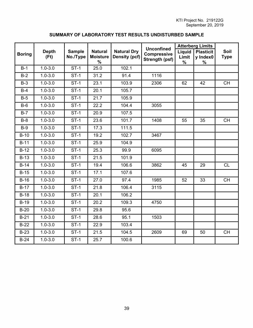
SUMMARY OF LABORATORY TEST RESULTS UNDISTURBED SAMPLE
Boring Depth (Ft)
Sample No./Type
Natural
Moisture %
Natural Dry Density (pcf)
Unconfined Compressive Strength (psf)
Atterberg Limits Soil Type
Liquid Limit
%
Plasticity Index0
% B-1 1.0-3.0 ST-1 25.0 102.1 B-2 1.0-3.0 ST-1 31.2 91.4 1116 B-3 1.0-3.0 ST-1 23.1 103.9 2306 62 42 CH B-4 1.0-3.0 ST-1 20.1 105.7 B-5 1.0-3.0 ST-1 21.7 105.9 B-6 1.0-3.0 ST-1 22.2 104.4 3055 B-7 1.0-3.0 ST-1 20.9 107.5 B-8 1.0-3.0 ST-1 23.6 101.7 1408 55 35 CH B-9 1.0-3.0 ST-1 17.3 111.5
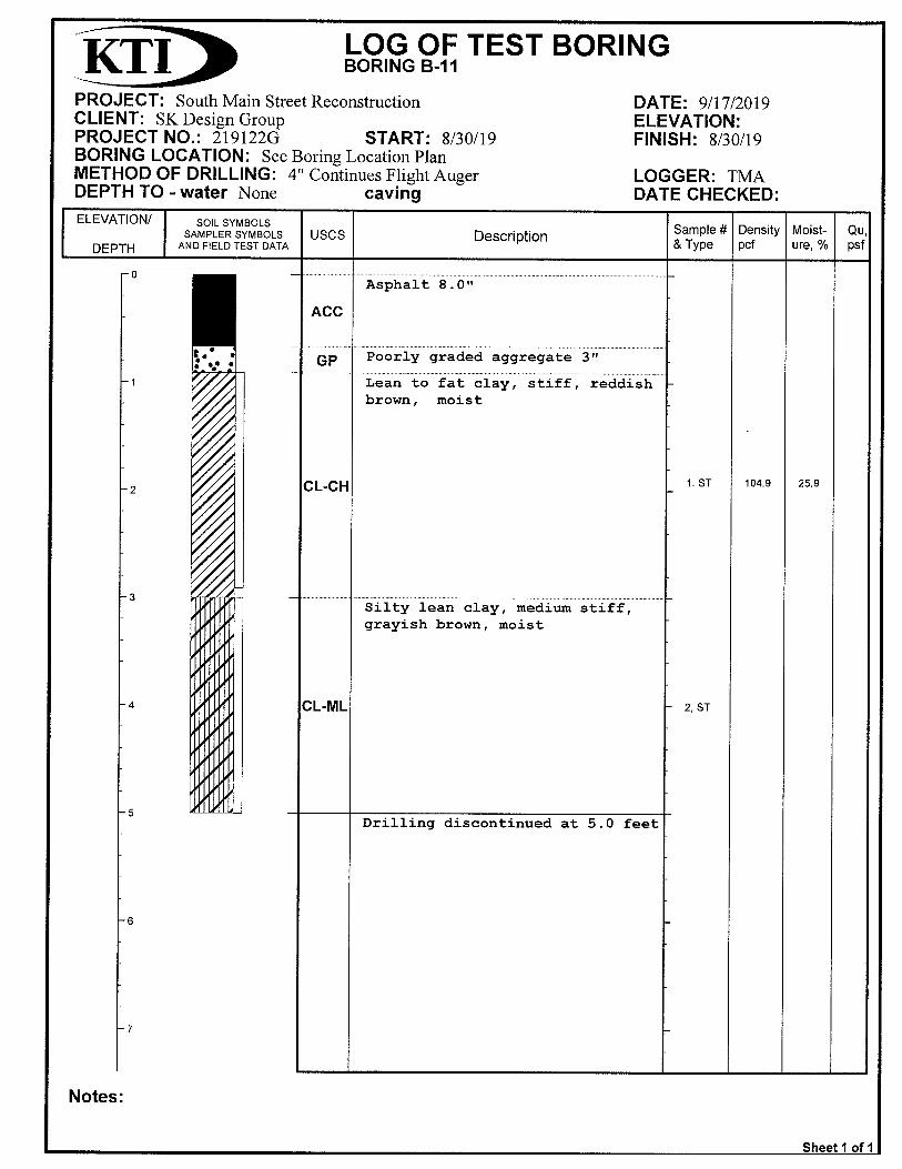
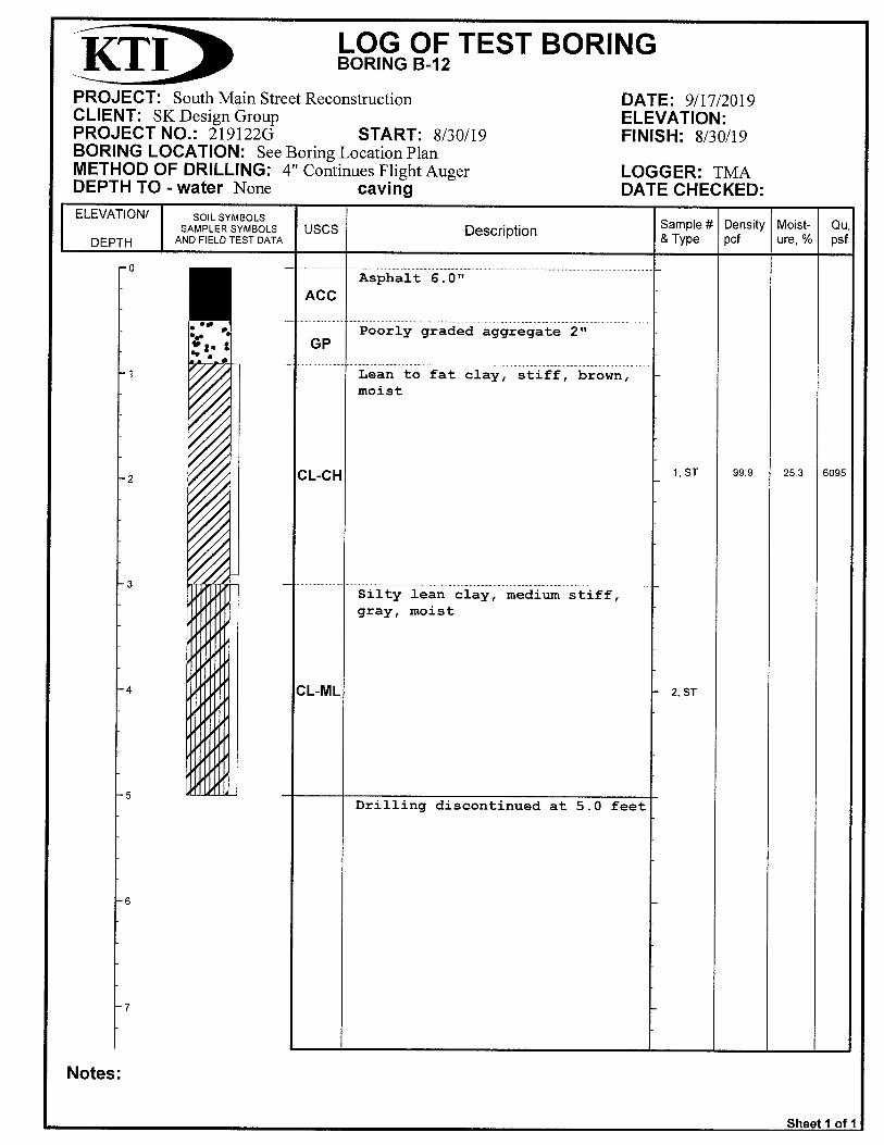
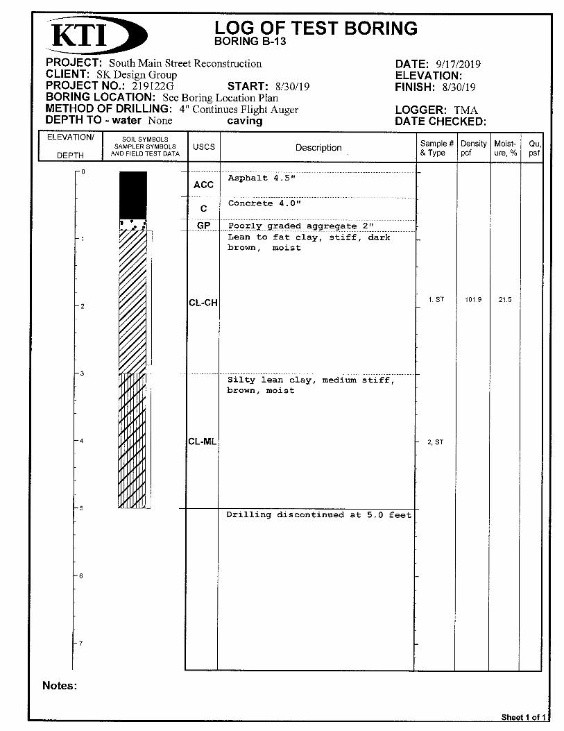
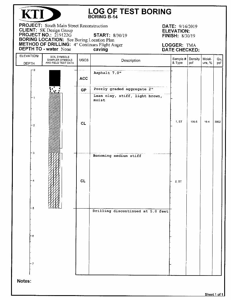
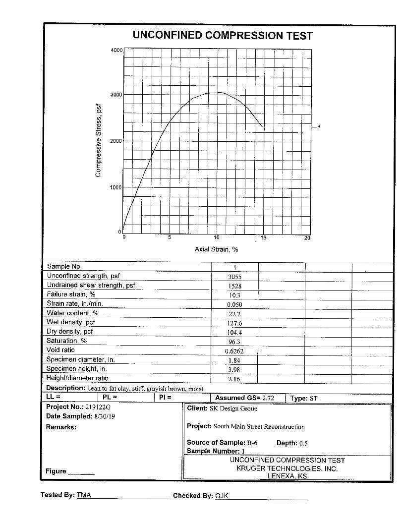
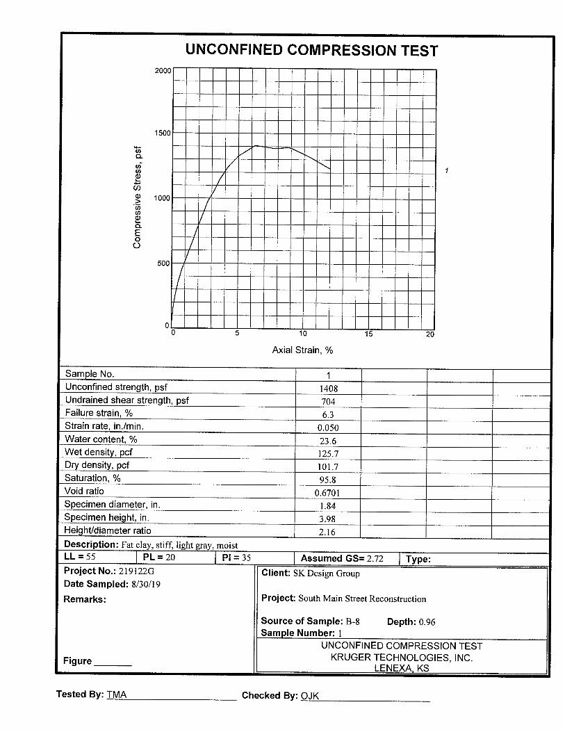
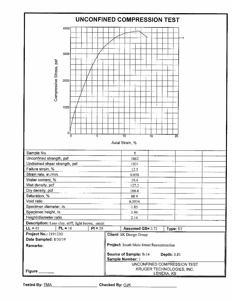
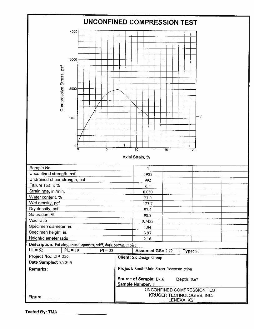
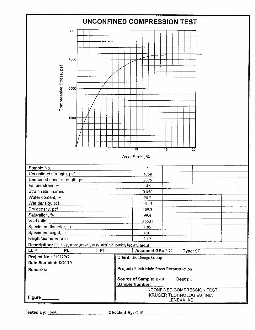
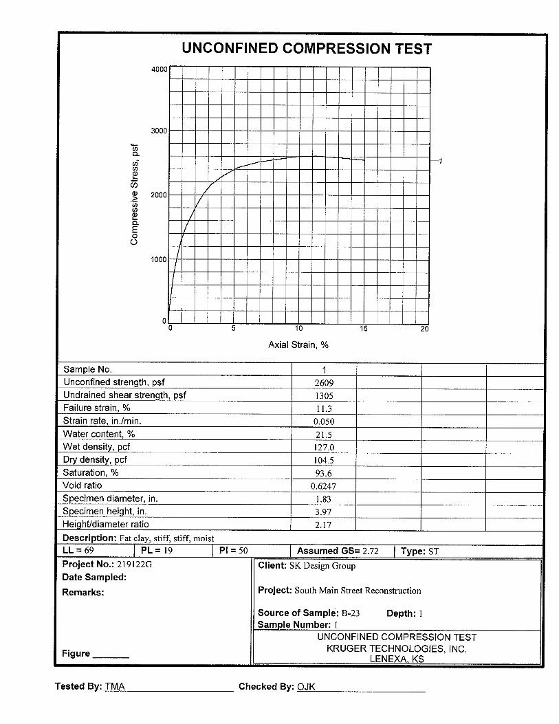
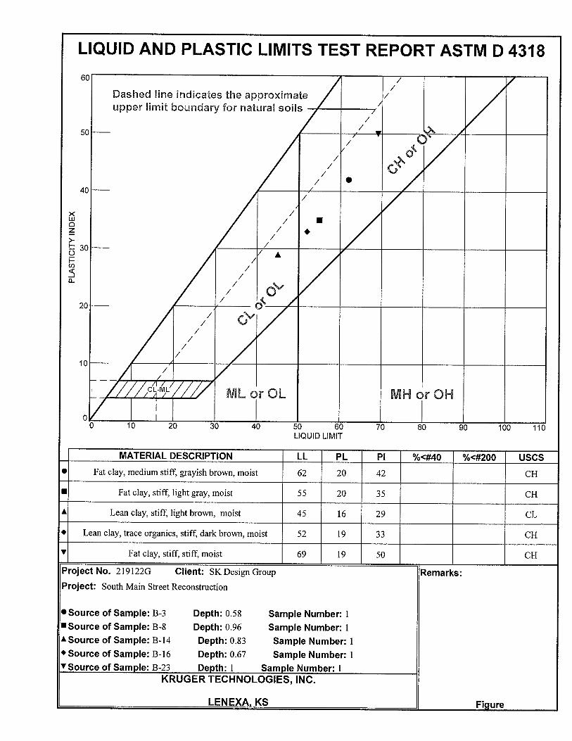
B-10 1.0-3.0 ST-1 19.2 102.7 3467 B-11 1.0-3.0 ST-1 25.9 104.9 B-12 1.0-3.0 ST-1 25.3 99.9 6095 B-13 1.0-3.0 ST-1 21.5 101.9 B-14 1.0-3.0 ST-1 19.4 106.6 3862 45 29 CL B-15 1.0-3.0 ST-1 17.1 107.6 B-16 1.0-3.0 ST-1 27.0 97.4 1985 52 33 CH B-17 1.0-3.0 ST-1 21.8 106.4 3115 B-18 1.0-3.0 ST-1 20.1 106.2 B-19 1.0-3.0 ST-1 20.2 109.3 4750 B-20 1.0-3.0 ST-1 29.8 95.6 B-21 1.0-3.0 ST-1 28.6 95.1 1503 B-22 1.0-3.0 ST-1 22.9 103.4 B-23 1.0-3.0 ST-1 21.5 104.5 2609 69 50 CH B-24 1.0-3.0 ST-1 25.7 100.6


KTI Project No. 219122G September 20, 2019
53
GLOSSARY OF GEOTECHNICAL TERMS
ALLUVIUM Sediments deposited by streams, including riverbeds and floodplains.
ARGILLACEOUS Rocks composed of or having a notable portion of fine silt and/or
clay in their composition. ATTERBERG LIMITS Water contents, in percentage of dry weight of soil, that correspond
to the boundaries between the states of consistency, i.e. the boundary between the liquid and plastic states (liquid limit) and the boundary between the plastic and solid states (plastic limit).
BEDROCK-IN-PLACE Continuous rock mass which essentially has not moved from its
original depositional position. CALCAREOUS Containing calcium carbonate determined by effervescence when
tested with dilute hydrochloric acid. CHANNEL SANDSTONE Sandstone that has been deposited in a streambed or other channel
eroded into the underlying beds. COLLUVIAL Rock debris of various sizes loose from in-place bedrock mass, often
shifted down gradient in conjunction with soil. CROSS-BEDDING Stratification which is inclined to the original horizontal surface upon
which the sediment accumulated. FISSILE BEDDING Term applied to bedding which consists of laminae less than 2
millimeters in thickness. FORMATION A distinctive body of rock that serves as a convenient unit for study
and mapping. FOSSIL DETRITUS The accumulation of broken, fragmented fossil debris. FOSSILIFEROUS Containing organic remains. GLACIAL ERRATIC A transported rock fragment different from the bedrock on which it
lies, either free or as part of a sediment. GLACIAL TILL Nonsorted, nonstratified sediment carried or deposited by a glacier. GLACIOFLUVIAL Primarily deposited by streams from glaciers. GROUP A lithostratigraphic unit consisting of two or more formations. JOINT A fracture in a rock along which no appreciable displacement has
occurred.
KTI Project No. 219122G September 20, 2019
54
LIMESTONE A sedimentary rock composed mostly of calcium carbonate (CaCO3). LOESS A homogenous, nonstratified, unindurated deposit consisting
predominantly of silt, with subordinate amounts of very fine sand and/or clay.
MICA A mineral group, consisting of phyllosilicates, with sheetlike
structures. MEMBER A specially developed part of a varied formation is called a member,
if it has considerable geographic extent. NODULE A small, irregular, knobby, or rounded rock that is generally harder
than the surrounding rock. PERMEABILITY The capacity of a material to transmit a fluid. RECOVERY The percentage of bedrock core recovered from a core run length. RELIEF The difference in elevation between the high and low points of a land
surface. RESIDUAL SOIL Soil formed in place by the disintegration and decomposition of rocks
and the consequent weathering of the mineral materials. ROCK QUALITY DESIGNATION (RQD)
Refers to percentage of core sample recovered in unbroken lengths of 4 inches or more.
SANDSTONE Sedimentary rock composed mostly of sand sized particles, usually
cemented by calcite, silica, or iron oxide. SERIES A time-stratigraphic unit ranked next below a system. SHALE A fine-grained plastic sedimentary rock formed by consolidation of
clay and mud. STRATIGRAPHY Branch of geology that treats the formation, compositions, sequence,
and correlation of the stratified rocks as parts of the earth's crust. SYSTEM Designates rocks formed during a fundamental chronological unit, a
period. UNCONFORMITY A surface of erosion or nondeposition, usually the former, which
separates younger strata from older rocks. WEATHERING The physical and chemical disintegration and decomposition of rocks
and minerals.
KTI Project No. 219122G September 20, 2019
55
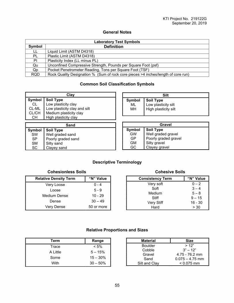
General Notes
Laboratory Test Symbols Symbol Definition
LL Liquid Limit (ASTM D4318) PL Plastic Limit (ASTM D4318) PI Plasticity Index (LL minus PL) Qu Unconfined Compressive Strength, Pounds per Square Foot (psf) Qp Pocket Penetrometer Reading, Tons per Square Foot (TSF)
RQD Rock Quality Designation % (Sum of rock core pieces >4 inches/length of core run)
Common Soil Classification Symbols
Descriptive Terminology
Cohesionless Soils Cohesive Soils
Relative Proportions and Sizes
Clay Symbol Soil Type
CL Low plasticity clay CL-ML Low plasticity clay and silt CL/CH Medium plasticity clay
CH High plasticity clay
Silt Symbol Soil Type
ML Low plasticity silt MH High plasticity silt
Sand Symbol Soil Type
SW Well graded sand SP Poorly graded sand SM Silty sand SC Clayey sand
Gravel Symbol Soil Type
GW Well graded gravel GP Poorly graded gravel GM Silty gravel GC Clayey gravel
Relative Density Term “N” Value Very Loose 0 - 4
Loose 5 - 9 Medium Dense 10 - 29
Dense 30 – 49 Very Dense 50 or more
Consistency Term “N” Value Very soft 0 – 2
Soft 3 – 4 Medium 5 – 8
Stiff 9 – 15 Very Stiff 16 - 30
Hard > 30
Term Range Trace < 5% A Little 5 – 15% Some 15 – 30% With 30 – 50%
Material Size Boulder > 12” Cobble 3” – 12” Gravel 4.75 - 76.2 mm Sand 0.075 – 4.75 mm
Silt and Clay < 0.075 mm