southern nuclear j. j. hutto post office box 1295 ... · farley fsar_ch11, ch12, ch13, ch14, ch15,...
TRANSCRIPT

~ Southern Nuclear
APR 2 0 2017
Docket Nos.: 50-348 50-364
U.S. Nuclear Regulatory Commission ATTN: Document Control Desk Washington, 0. C. 20555-0001
J. J. Hutto Regulatory Affairs Director
Joseph M. Farley Nuclear Plant
40 Inverness Center Parkway Post Office Box 1295 Birmingham, 35242 205 992 5872 tel 205 992 7601 fax
NL-17-0534
Updated Final Safety Analysis Report, 1 O CFR 50.59 Report, Fire Hazard Analysis Changes, Technical Specifications Bases Changes, Technical
Requirements Manual Changes, and Revised NRC Commitments Report
Ladies and Gentlemen:
In accordance with the 1 O CFR 50.4(b) and 50.71 (e), Southern Nuclear Operating Company (SNC) hereby submits Revision 27 to the Joseph M. Farley Nuclear Plant (FNP) Updated Final Safety Analysis Reports (UFSAR). The revised FNP UFSAR pages reflect changes through the middle of April 2017.
The FNP Technical Specifications, section 5.5.14, "Technical Specifications (TS) Bases Control Program," provides for changes to the Bases without prior NRC approval. In addition, TS section 5.5.14 requires that Bases changes made without prior NRC approval be provided to the NRC on a frequency consistent with 10 CFR 50.71 (e). Pursuant to TS 5.5.14, SNC hereby submits a complete copy of the FNP TS Bases. The revised FNP TS Bases pages, indicated as Revision 81 for Units 1 and 2, reflect changes through March 2017.
In accordance with Regulatory Issue Summary (RIS) 2001-05, "Guidance on Submitting Documents to the NRC by Electronic Information Exchange or on CD-ROM," all the current pages of the FNP UFSAR, TS Bases, Technical Requirements Manual (TRM), and NFPA 805 Fire Protection Program Design Basis Document are being submitted on CD-ROM in portable document format (PDF) with non-proprietary browser included. The revised FNP TRM pages, indicated as Revision 35 for Units 1 and 2, reflect changes through March 2017. The updated NFPA 805 Fire Protection Program Design Basis Document is included revised on December 19, 2016.
In accordance with the requirements of 1 O CFR 50.59(d)(2), SNC hereby submits the 1 O CFR 50.59 Report containing a brief description of any changes, tests, or experiments, including a summary of the safety evaluation of each.
U. S. Nuclear Regulatory Commission NL-17-0534 Page 2
In accordance with NEI 99-:04, "Guideline for Managing NRC Commitment Changes," Revision 0, SNC is required to submit a Revised NRC Commitments Report. SNC hereby submits a Revised NRC Commitments Report in Enclosure 4 with commitment revisions made from August 2015 through March 2017.
Enclosure 1 provides a table of contents with associated file names for the CD-ROM (Enclosure 2). Enclosure 3 provides the 10 CFR 50.59 Report, and Enclosure 4 provides the Revised NRC Commitments Report.
This letter contains no NRC commitments. If you have any questions, please contact Ken McElroy at 205.992.7369.
Mr. J. J. Hutto states he is the Regulatory Affairs Director for Southern Nuclear Operating Company, is authorized to execute this oath on behalf of Southern Nuclear Operating Company and, to the best of his knowledge and belief, the facts set forth in this letter are true.
Respectfully submitted,
J. J. Hutto Regulatory Affairs Director
JJH/GLS/lac
My commission expires: / 0 - ti- d-O I ,_,,
Enclosures: 1. CD-ROM Table of Contents CD-ROM NRG Submittal 1 O CFR 50.59 Report
----'-'4(2&f!~<-==-------' 2017.
2. 3. 4. Revised NRG Commitments Report
\.
/'
- ·, s ,1
'"·_:;;'
I ~ '
U. S. Nuclear Regulatory Commission NL-17-0534 Page 3"
cc: Southern Nuclear Operating Company Mr. S. E. Kuczynski, Chairman, President & CEO (w/o enclosures) Mr. D. G. Bost, Executive Vice President & Chief Nuclear Officer (w/o enclosures) Mr. M. D. Meier, Vice President- Regulatory Affairs (w/o enclosures) Mr. D. R. Madison, Vice President - Farley (w/o enclosures) Mr. R. D. Gayheart, Fleet Operations General Manager (w/o enclosures) 'Mr. B. J. Adams, Vice President - Engineering (w/o enclosures) Ms. B. L. Taylor, Regulatory Affairs Manager - Farley (w/o enclosures) RType: CFA04.054
U.S. Nuclear Regulatory Commission Ms. C. Haney, Regional Administrator (w/o enclosures) Mr. S. A. Williams, Senior NRR Project Manager - Farley (w/o enclosures) Mr. P. K. Niebaum, Senior Resident Inspector- Farley (w/o enclosures)
Institute of Nuclear Power Operations Mr. Dane R. Williams, INPO Emergency Management Manager (Enclosure 2 - CD ROM only)
Joseph M. Farley Nuclear Plant Updated Final Safety Analysis Report, 1 O CFR 50.59 Report, Fire Hazard Analysis Changes, Technical Specifications Bases Changes, Technical Requirements Manual Changes, and Revised NRC Commitments Report
Enclosure 1
CD-ROM Table of Contents
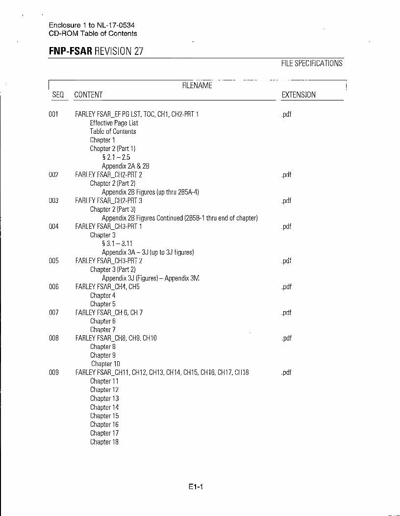
Enclosure 1 to NL-17-0534 CD-ROM Table of Contents
FNP-FSAR REVISION 27
I FILENAME SEQ CONTENT
001
002
003
004
005
006
007
008
009
FARLEY FSAR_EF PG LST, TDC, CH1, CH2-PRT 1 Effective Page List Table of Contents Chapter 1 Chapter 2 (Part 1)
§ 2.1 -2.5 Appendix 2A & 2B
FARLEY FSAR_CH2-PRT 2 Chapter 2 (Part 2)
Appendix 2B Figures (up thru 2B5A-4) FARLEY FSAR_CH2-PRT 3
Chapter 2 (Part 3) Appendix 2B Figures Continued (2B5B-1 thru end of chapter)
FARLEY FSAR_CH3-PRT 1 Chapter 3
§ 3.1 - 3.11 Appendix 3A- 3J (up to 3J figures)
FARLEY FSAR_CH3-PRT 2 Chapter 3 (Part 2)
Appendix 3J (Figures) -Appendix 3M FARLEY FSAR_CH4, CH5
Chapter 4 Chapter 5
FARLEY FSAR_CH 6, CH 7 Chapter 6 Chapter 7
FARLEY FSAR_CH8, CH9, CH10 Chapter 8 Chapter 9 Chapter 10
FARLEY FSAR_CH11, CH12, CH13, CH14, CH15, CH16, CH17, CH18 Chapter 11 Chapter 12 Chapter 13 Chapter 14 Chapter 15 Chapter 16 Chapter 17 Chapter 18
E1-1
FILE SPECIFICATIONS
EXTENSION
Enclosure 1 to NL-17-0534 CD-ROM Table of Contents
FNP-FSAR REVISION 27
I FILENAME SEO CONTENT
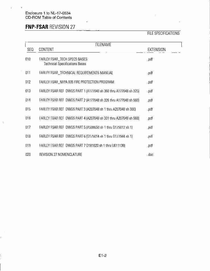
010 FARLEY FSAR_TECH SPECS BASES Technical Specifications Bases
011 FARLEY FSAR_TECHNICAL REQUIREMENTS MANUAL
012 FARLEY FSAR_NFPA 805 FIRE PROTECTION PROGRAM
013 FARLEY FSAR REF OWGS PART 1 (A 177040 sh 360thruA177048 sh 325)
014 FARLEY FSAR REF OWGS PART 2 (A 177048 sh 326thruA177048 sh 568)
015 FARLEY FSAR REF OWGS PART 3 (A207048 sh 1 thru A207048 sh 300)
016 FARLEY FSAR REF OWGS PART 4 (A207048 sh 301 thru A207048 sh 568)
017 FARLEY FSAR REF OWGS PART 5 (A508650 sh 1thru0175012 sh 1)
018 FARLEY FSAR REF OWGS PART 6 (0175014 sh 1thru0177944 sh 1)
019 FARLEY FSAR REF OWGS PART 7 0181620 sh 1 thru U611138)
020 REVISION 27 NOMENCLATURE
E1-2
FILE SPECIFICATIONS
EXTENSION
.doc

Joseph M. Farley Nuclear Plant Updated Final Safety Analysis Report, 1 O CFR 50.59 Report, Fire Hazard Analysis Changes, Technical Specifications Bases Changes, Technical Requirements Manual Changes, and Revised NRC Commitments Report
Enclosure 2
CD-ROM NRC Submittal
Joseph M. Farley Nuclear Plant Updated Final Safety Analysis Report, 1 O CFR 50.59 Report, Fire Hazard Analysis Changes, Technical Specifications Bases Changes, Technical Requirements Manual Changes, and Revised NRC Commitments Report
Enclosure 3
1 O CFR 50.59 Report
Enclosure 3 to NL-17-0534 10 CFR 50.59 Report
1 O CFR 50.59 Summary Report
Activity: Design Changes SNC634837 and SNC582588MDC
Title: Unit 1 and Unit 2 Reactor Coolant Pump (RCP) Shutdown Seal (SOS) Generation Ill installation
1 O CFR 50.59 Evaluation Summary: The proposed activity is to replace the current SOS Generation I and I-hybrid and the RCP number 1 seal insert in each Farley Unit 1 model 93A RCP with a modified design SOS generation Ill. The proposed activity also replaced the Farley Unit 2 RCP Shutdown Seals (SOS) Generation II and No. 1 Seal Inserts with a modified design SOS generation Ill. Incorporated in the SOS assembly is a passive temperature-activated device that performs a sealing function between the SOS and the RCP shaft sleeve. The sealing function is designed to occur only when the SOS experiences an elevated temperature in the number 1 seal leakoff fluid, which would occur as a result of the coincident loss of all thermal barrier heat exchanger cooling and No. 1 seal injection cooling. Screening question number 1 identified potential adverse effects on a SSC described in the UFSAR. The aspects of the normal use of the SOS (inactive) and the potential effects of inadvertent actuation of the SOS have been evaluated in Section C of this evaluation.
The Farley Technical Specifications (TS) were reviewed, including sections 3.4.13; 3.5.5 and their associated TS Bases. Implementation of the SOS does not necessitate changes to the TS or TS Bases.
It is concluded that the proposed activity does not require prior Nuclear Regulatory Commission (NRC) approval before its implementation and the plant is returned to power operation. The activity may be implemented at Farley Unit 1 and Unit 2 without requiring SNC to request a License Amendment.
Per ML4132A 128, 5/28/14, NRG Acceptance Letter tor Generation /II SOS, the NRC endorsed the use of the Westinghouse SOS generation Ill for Westinghouse RCP models 93, 93A and 93A-1. It also concluded that it is acceptable crediting the SOS during an extended loss of alternate current power (ELAP) event as described in TA-FSE-14-1-P, Revision 1, Use of Westinghouse SHIELD Passive Shutdown Seal for FLEX Strategies, March 2014, with specific limitations and conditions described in NRG Acceptance Letter tor Generation Ill SOS. As documented in WCAP-17601-P, Revision 0, Reactor Coolant System Response to the Extended Loss of AC Power Event for Westinghouse, Combustion Engineering ad Babcock & Wilcox NSSS Designs and LTR-LIS-15-159, Revision 0, Limiting Cold Leg Temperature During a Transient at Farley, the limitations and conditions described in the NRG Acceptance Letter tor Generation Ill SOS are currently met by the Farley Unit 1 and Unit 2 reactor coolant system and seal injection system design.
Activity: Design Change SNC87993
Title: Farley Nuclear Plant Turbine Building Roof Replacement
1 O CFR 50.59 Evaluation Summary: The existing built-up asphalt and gravel roofing system on the Unit 1 & 2 turbine building is being replaced with a new insulated cold liquid applied membrane roofing system. In addition to the main roof, the roofing systems for the
E3-1
Enclosure 3 to NL-17-0534 10 CFR 50.59 Report
three stairway enclosures, the HVAC Equipment Room, and the roofs over two tube-pull spaces are being replaced.
The turbine building roof smoke/heat vents are changing from a spring-loaded, heat fusiblelink operated design to a passive, gravity ventilator design. Per UFSAR Section 9.4.4.1.1, the turbine building heating and cooling system: (A) provides temperature and humidity control for personnel working conditions and optimum equipment performance, and (C) provides recirculation of indoor air. Modification to the turbine building roof smoke/heat vents adversely affects these design functions. Recirculation of indoor air can no longer be assured since preferred airflow patterns will not be maintained now that the roof vents are always open. This may result in a decrease in the heating effectiveness during winter shutdown heating. However, the turbine building heating and cooling system is not credited when analyzing the probabilities and consequences of accidents and malfunctions of SSC's important to safety in the Farley UFSAR. Based on a review of UFSAR Section 9.4.4 and Chapter 15, the turbine building heating and cooling system does not affect any SSCs important to safety. The turbine building heating and cooling system has no interface with any fission product barriers. No accidents are postulated for any failure modes or SSC interfaces associated with the turbine building heating and cooling system.
Therefore, when compared to previous UFSAR evaluations, the turbine building roof smoke/heat vent design does not result in more than a minimal increase in the frequency of occurrence or consequences of accidents and malfunctions of SSCs important to safety, create the possibility of accidents of a different type than previously evaluated, create the possibility for malfunctions of SSCs important to safety with a different result than previously evaluated, nor impact the integrity of fuel cladding, reactor coolant pressure boundary, or containment.
Activity: Design Change SNC87848
Title: Replace Governor on 1 C Diesel Generator
10 CFR 50.59 Evaluation Summary: Design Change Package (DCP) SNC87849 provides the design, installation instructions, and testing requirements necessary to replace the existing 1 C EOG governor speed control system with a new qualified Woodward governor speed control system components consisting of a 2301 A analog speed controller, a Digital Reference Unit (DRU), and a proportional governor actuator (EGB-13P). A Magnetic Pickup (MPU) is provided to supply an engine speed input signal to the 2301A, and a RATED/IDLE selector switch is provided to allow the engine to be started at idle speed for testing.
The weight inside the Diesel Local Control Panel (DLCP) is increased by 21 pounds with the installation of the new components. The additional weight is evaluated, and it is determined that there is no adverse impact on the seismic integrity of the panel.
The additional heat load is 952 BTU/hr (less than 0.13% increase) and is insignificant in relation to the total heat load in the room; Per MC-F-13-0006, Verification of Diesel Generator Building Ventilation and Heating System (Base Calculation SM-92-2216-01, Version 3.0), the design heat load is 897,240 BTU/hr, and the new heat load per DCP SNC87849 is 778, 105 BTU/hr. Therefore, there is still 119, 135 BTU/hr of HVAC margin available.
E3-2

Enclo~ure 3 to NL-17-0534 1 O CFR 50.59 Report
The electrical load is increased by 4.1 amps, which results in an acceptable Battery Bank 1A margin of 29.7% and Battery Bank 2A margin of 35.5%. The resulting margins are adequate for the performance of the design function based on the modification calculation referenced.
Based on the responses to the evaluation questions in Section C, the proposed activity will not result in:
• an increase of frequency of accident occurrence or likelihood of malfunction of a SSC important to safety previously evaluated in the Updated FSAR.
• an increase in consequences of an accident or malfunction of a SSC important to safety previously evaluated in the Updated FSAR.
• an increase in the possibility for an accident of a different type or malfunction of a SSC important to safety of a SSC important to safety previously evaluated in the Updated FSAR.
• an impact on the integrity of fuel cladding, reactor coolant pressure boundary, or containment; or design basis of a fission product barrier previously evaluated in the Updated FSAR.
• a departure from a method of evaluation described in the Updated FSAR used in establishing the design bases or in the safety analyses.
Activity: Design Change SNC327824
Title: Solid State Protection System (SSPS) Upgrades Unit 2 Part 2
1 O CFR 50.59 Evaluation Summary: This modification replaces Unit 2 Westinghouse Solid State Protection System (SSPS) original design printed circuit boards with the Westinghouse new design boards. The SSPS boards are being replaced to improve reliability. The original design boards covered by this full evaluation are: the Clock Counter (CCB), Decoder (DEC), Isolation (ISO), and Memory (MEM) printed circuit boards. The new design SSPS boards use a Complex Programmable Logic Device (CPLD) to accomplish the board-specific digital logic design functions instead of a Motorola High Threshold Logic (MHTL) ICs. CPLDs do not utilize software while the system is in operation. Instead, the development of these systems uses software to generate a hardware layout to be implemented in the CPLD. CPLDs are programmed, and that programming is performed in a manner similar to traditional microprocessor based software program development. The use of software in the configuration of the CPLD poses a potential adverse impact to the design function of the replacement CCB, DEC, and MEM boards, which requires this change to be screened in for further evaluation, because the new CPLD-based boards will be installed in both SSPS trains.
CCB, DEC and ISO boards are located in the Unit 2 Main Control Room (Room 4_01), inside SSPS Cabinets Q2H11 NGSSP2506L {Train A) and Q2H11 NGSSP2506H {Train B). The nuclear safety and seismic classifications of the replacement boards are the same as the boards being replaced. The SSPS Cabinets and boards are safety related and seismic category I.
DEC and MEM boards are located in the Unit 2 Cable Spreading Room (Room 2318), inside the SSPS Control Board Demultiplexer (Demux) Cabinet N2H25L0041 A, and in the Unit 2 Computer Room (Room 2201), in the SSPS Computer Demux Assembly inside Computer Input I Output Cabinet N2C41 G0004B. The nuclear safety and seismic
E3-3

Enclosure 3 to NL-17-0534 10 CFR 50.59 Report
classifications of the replacement boards are the same as the boards being replaced. The Control Board Demux Cabinet and the SSPS Computer Demux Assembly inside the Computer Input I Output Cabinet are non-safety related and seismic category II/I; hence, the replacement boards in these cabinets are also non-safety related and classified seismic category II/I. The new design DEC board is qualified as safety related. The new design MEM board was subjected to rigorous qualification testing similar to the safety related boards, but it is manufactured as non-safety related.
The CCB, DEC, ISO, and MEM boards are support boards for testing and for multiplexing trip and actuation status to the plant computer and MCB demultiplexers. These support boards do not directly access or process any safety actuation signals. Implementation of the new design replacement boards constitutes a digital upgrade of the existing SSPS board because the boards utilize a CPLD to replace the MHTL logic devices used on the original design boards. This design is a component level upgrade and not a system upgrade. All aspects of this digital replacement were evaluated and determined to result in no new or additional failure modes. The SSPS design was developed by Westinghouse under a safety-related Appendix B program. Westinghouse performed an analysis of all the circuits on the CPLD using the appropriate vendor supplied tool, with the intention of demonstrating that the testing that was already performed met the "testability" criteria in BTP 7-19, Section 1.9(2), in order to eliminate consideration of Common Cause Failure (CCF). The analyses and testing are sufficiently rigorous and complete to eliminate consideration of CCF. No diverse system is required to address CCF of the CPLD based SSPS boards.
In section 4.0 of NRC Final Safety Evaluation (FSE) for PWROG Topical Report WCAP-17867-P-A, Revision 1, 'Westinghouse SSPS Board Replacement Licensing Summary Report", dated September 19, 2014, the FSE states, "Based on the evaluations, audits, and technical reviews summarized in this Safety Evaluation, the NRC staff concludes that the new design SSPS boards can be used to replace the original design boards." Section 4.2 prescribes four (4) plant-specific action items related to atmospheric operating environment, lifetime total integrated dose, EMl/RFI levels, and actuation logic testing. Three of these action items are explicitly addressed in this 1 O CFR 50.59 Evaluation as well as the modification implementation requirements. The actuation logic testing action item only applies to the new design ULB, UVD, SGD and SAT printed circuit boards, not the new design CCB, DEC, ISO and MEM printed circuit boards, and therefore is not addressed in detail herein.
Section 4.0 also states, ''The NRC staff also finds that the unique configuration of each plant makes it important that each licensee analyze whether the new design boards can be installed under 1 O CFR 50.59 without prior NRC approval." This Farley Nuclear Plant Unit 2 specific 10 CFR 50.59 Evaluation provides a documented basis for implementation of the Westinghouse new design SSPS CCB, DEC, ISO and/or MEM boards in any combination of new and original design SSPS boards without prior NRC approval.
All aspects of this change were evaluated for a change in all the parameters listed in Section C of this 50.59. Based on the evaluation above, the following has been determined:
• Implementation of new design SSPS replacement boards will not re,sult in a more than a minimal increase in the frequency of occurrence of an accident previously evaluated, since no new accident initiators are being introduced, and the reliability of the
E3-4
I

Enclosure 3 to NL-17-0534 10 CFR 50.59 Report
replacement boards was determined to exceed those of the existing boards based on a Mean Time Between Failure (MTBF) calculation.
• Implementation of new design SSPS replacement boards does not increase consequences of an accident previously evaluated in the FSAR because the Reactor Trip System (RTS) and Engineered Safety Features Actuation System (ESFAS) will continue to respond as assumed in the accident analyses.
• Implementation of new design SSPS replacement boards will not cause more than a minimal increase in the likelihood of occurrence of a malfunction of a SSC important to safety since the replacement boards were determined to be more reliable than the existing boards, and introduce no new system malfunctions as the result of any failures.
• Implementation of new design SSPS replacement boards does not result in more than a minimal increase in the consequences of a malfunction of a SSC important to safety previously evaluated in the FSAR.
• Implementation of new design SSPS replacement boards will not have any adverse impact on other equipment and does not create the possibility of an accident of a different type than was previously evaluated in the FSAR.
• Implementation of new design SSPS replacement boards does not increase the possibility for a malfunction of a SSC important to safety with a different result than was previously evaluated in the FSAR as the failure modes and effects determined that the replacement boards are essentially transparent to the plant, as compared with the original design boards with respect to plant response at the system level to failures or malfunctions.
• The new design SSPS replacement boards do not have any impact on the integrity of the fuel cladding, fuel pellet, reactor pressure coolant boundary or containment structure. Thus, this design change does not result in a design basis safety limit change or new transient challenge for a fission product barrier (i.e., numerical limiting value for controlling the integrity of the fuel cladding and pellet, reactor coolant pressure boundary and/or containment building) being revised or altered. In addition, the replacement boards will not alter nor affect the validity of the existing ANS Condition II, Ill and IV transient and accident analyses.
• Implementation of new design SSPS replacement boards will not result in a departure from a method of evaluation described in the FSAR used in establishing the design bases or in the safety analyses.
Therefore, the activity to which this evaluation applies does not represent a change to the parameters that have already been evaluated in the FSAR.
Activity: Design Change SNC52886
Title: Unit 1 Main Turbine (DEH) Controls Upgrade
1 O CFR 50.59 Evaluation Summary: This DCP replaces the existing WDPF controls for the turbine in order to address the obsolescence of the existing Main Turbine Digital Electrohydraulic (DEH) control system. It eliminates the hard control interfaces on the main control board (MCB) for the balance of plant (BOP) controls. The new system utilizes Ovation based Distributed Control System (DCS), which has numerous components that are microprocessor based. Therefore this change is considered a digital upgrade and much of its functionality will be controlled through software, which introduces the possibility of a software failure causing a DEH control system malfunction. The guidance of NEI 01-01 has been used to evaluate the system with respect to new digital upgrades.
E3-5
Enclosure 3 to NL-17-0534 10 CFR 50.59 Report
All aspects of this change were evaluated for a change in all the parameters listed in Section C of this 50.59. The accidents evaluated are two Condition II events per Chapter 15 of the UFSAR: (1) 15.2.7-Loss of External Load and/or Turbine Trip, and (2) 15.2.1-Excessive Load Increase Incident (caused by turbine speed control malfunction). The SSC that the Turbine Control System (TCS) interfaces with and/or impacts is the Reactor Protection System (RPS) (concern is safety system challenges resulting in increased reactor trips). Based on the evaluation above, following has been determined:
• This design change will not result in a more than a minimal increase in the frequency of occurrence of an accident previously evaluated in the Updated FSAR since TCS interface with reactor protection system is unchanged, and reliability and functionality of the new system is comparable with the existing Westinghouse Distributed Processing Family (WDPF) based system. Safety system challenges to the RPS (reactor trips) will thus be comparable.
• This design change will not cause more than a minimal increase in the likelihood of occurrence of a malfunction of an SSC important to safety since the failure modes and the corresponding frequency of occurrence of the new system are comparable to those found in the existing network configurations. All the existing interfaces of the TCS with the reactor protection system remain intact and unchanged. Safety system challenges to the RPS (reactor trips) are comparable.
• This design change does not increase consequences of an accident previously evaluated in the FSAR because the new TCS is not required to mitigate consequences of any accident, the functional responses of the new system are consistent with those of the existing system and all the existing interfaces of the TCS with the reactor protection system remain unchanged.
• This design change does not result in more than a minimal increase in the consequences of a malfunction of an SSC important to safety previously evaluated in the FSAR because the TCS itself is not a safety-related system nor is it required to mitigate the consequences of an accident. Also all the existing interfaces of the TCS with the reactor protection system are unchanged. The failure modes of the new system are comparable with the existing WDPF based system.
• This design change does not create the possibility for an accident of a different type than any previously evaluated in the Updated FSAR because failure modes of the new system are comparable with those of the existing system and FMEA for the new system did not reveal any new failure modes that constitute a new type of failure if TCS fails. Interfaces with the reactor protection system are unchanged, and no new SSC interfaces are created, thus no different type of accidents are postulated.
• The upgraded TCS equipment will not create the possibility for a malfunction of an SSC important to safety with a different result than was previously evaluated in the FSAR because all the existing interfaces of the TCS with the reactor protection system remain intact and unchanged. Specifically, the turbine trip/reactor trip and excessive load trip are unaffected by this modification, and no additional SSC interfaces are created.
• This TCS modification does not have any impact on the integrity of the fuel cladding, reactor coolant pressure boundary, or containment. The only indirect interface is via the reactor protection system. However, successful FAT, satisfactory FMEA analysis, and industry compliant software testing ensure that the TCS performance, reliability, and failure modes/probability do not have any adverse impact on the RPS.
• This design change is not applicable to the method of evaluation described in the FSAR used in establishing the design bases or in the safety analyses.
E3-6
Enclosure 3 to NL-17-0534 10 CFR 50.59 Report
Activity: Design Change SNC594819
Title: Unit 2 Addition .of Auto Isolation Valves between the refueling water storage tank (RWST) and refueling water purification pump (RWPP) Loop
1 O CFR 50.59 Evaluation Summary: This design change will address the installation of two ASME Section 111, Class 2 air operated ball valves and control circuits at the downstream end of valve Q2G31V010 to act as the safety related isolation boundary on a safety injection actuation signal (SIAS) and on a selected level set point of the RWST. The train-oriented circuits are routed and installed according to the separation requirements of Updated FSAR Appendix 3A. Safety- related interposing relays provide isolation between safety-related and non-safety-related circuits. The existing level transmitter setpoints are acceptable and do not require further modification. Modifications to the balance of plant (BOP) cabinets are made in accordance with established site practices and will not adversely affect the ability of the equipment to perform its design function. Additionally, these valves will fail closed on a loss of air or power. These two ball valves will provide automatic isolation between the RWST and the non-seismically qualified spent fuel pool (SFP) purification loop piping and therefore will eliminate the need for manual operator actions and satisfy the NRC's requirements. The additional isolation and redundancy decrease the consequences of an accident. This activity would permanently substitute manual action with automatic action for performing Updated FSAR-described design functions; therefore, the following would result from performing this activity:
a. Will not result in more than a minimal increase in the frequency of occurrence of an accident previously evaluated in the Updated FSAR;
b. Will not result in more than a minimal increase in the likelihood of occurrence of a malfunction of a structure, system, or component (SSC) important to safety;
c. Will not result in more than a minimal increase in the consequences of an accident previously evaluated in the Updated FSAR;
d. Will not result in more than a minimal increase in the consequences of a malfunction of a SSC important to safety previously evaluated in the Updated FSAR;
e. Will not create the possibility for an accident of a different type than any previously evaluated in the Updated FSAR;
f. Will not create the possibility for a malfunction of a SSC important to safety with a different result than any previously evaluated in the Updated FSAR; and
g. Will not have any impact on the integrity of the fuel cladding, reactor coolant pressure boundary, or containment.
h. Will not impact existing evaluations.
Activity: Design Change SNC50734
Title: Replace Governor on 1 B Diesel Generator
1 O CFR 50.59 Evaluation Summary: Design Change Package (DCP) SNC50734 provides the design, installation instructions, and testing requirements necessary to replace the existing 1 B Emergency Diesel Generator (EOG) governor speed control system with a new qualified Woodward governor speed control system components consisting of a 2301 A analog speed controller, a Digital Reference Unit (DRU), and a proportional governor actuator (EGB-50P). A magnetic pickup (MPU) is provided to supply an engine speed input signal to the 2301A, and a RATED/IDLE selector switch is provided to allow the engine to be started at idle speed for testing.
E3-7
Enclosure 3 to NL-17-0534 10 CFR 50.59 Report
The weight inside the Diesel Local Control Panel (DLCP) is increased with the installation of the new components. The additional weight is evaluated, and it is determined that there is no adverse impaCt on the seismic integrity of the panel.
The additional heat load is 952 BTU/hr (less than 0.07% increase) and is insignificant in relation to the total heat load in the room. The design heat load is 1,655,830 BTU/hr and the new heat load per DCP SNC50734 is 1,528,716 BTU/hr. Therefore, there is still 127, 114 BTU/hr of HVAC margin available.
The electrical load is increased by 4.1 amps, which results in an acceptable Battery Bank 1 B margin of 41.2%. The resulting margin is adequate for the performance of the design function based on the modification calculation referenced.
Based on the responses to the evaluation questions in Section C the proposed activity will not result in:
• an increase of frequency of accident occurrence or likelihood of malfunction of a SSC important to safety previously evaluated in the Updated FSAR.
• an increase in consequences of an accident or malfunction of a SSC important to safety previously evaluated in the Updated FSAR.
• an increase in the possibility for an accident of a different type or malfunction of a SSC important to safety of a SSC important to safety previously evaluated in the Updated FSAR.
• an impact on the integrity of fuel cladding, reactor coolant pressure boundary, or containment; or design basis of a fission product barrier previously evaluated in the Updated FSAR.
• a departure from a method of evaluation described in the Updated FSAR used in establishing the design bases or in the safety analyses.
Activity: License Document Change Request (LDCR) 2016028
Title: Removal of 1-2S Load Center (LC) from Technical Specification Bases Table B3.8.9-1
10 CFR 50.59 Evaluation Summary: The identification of pertinent design functions is based on the SSCs that receive their power from the 1-2S LC. On the 1-2S LC load list, the SSCs were grouped into three categories: (a) SSCs that contain a design function, (b) SSCs that do not contain a design function, and (c) SSCs that are controlled by another process (e.g., fire protection equipment), for which 50.59 does not apply. Therefore, only the SSCs in groups (a) and (b) will be considered. The SSCs in group (b) (i.e., electrical transformers, diesel switchgear room HVAC-related equipment, service water MOVs, MCC space heaters, sump pumps, emergency evacuation lighting, electric fixtures and receptacles, support instrumentation and annunciators, refrigeration support equipment, sanitary support equipment, and computer room HVACrelated equipment) do not possess functions required by or necessary to comply with regulations, license conditions, orders or technical specification, or are credited in the safety analysis performed to meet NRC requirements. Furthermore, none of these SSCs perform functions that, if not performed, would initiate a transient or accident that the plant is required to withstand. Since none of the aforementioned criteria for an SSC possessing a design function are met, there are no design functions associated with these SSCs.
E3-8
Enclosure 3 to NL-17i0534 10 CFR 50.59 Report
The SSCs in group (a) contain the following design functions that will be considered in this Screen:
(1) Diesel Generator 2C (and associated supporting equipment) - Electrical bus 1 J is required to support operation of diesel generator 2C in the event of a Unit 1 or Unit 2 SBO [UFSAR 8.3.1.1.7.3].
(2) Diesel Fuel Oil Storage Pumps 5038 (1 C DG, TPNS number QSY52P0503B) and 5048 (2C DG, TPNS number OSY52P0504B). - Each diesel fuel oil storage tank has two transfer pumps that provide a redundant means for transferring fuel oil from the storage tanks to the day tanks and other storage tanks [UFSAR 9.5.4.2].
UFSAR section 8.3.1.1.7.1 states the following regarding diesel generator 2C: "Diesel generator 2C, being the alternate AC (AAC) for SBO events, is not considered a candidate for the design basis single failure.
UFSAR section 8.3.1.1.7.3 states the following regarding the equipment related to responding to a Station Black Out (SBO) event: "SBO is not a design basis accident (OBA). Therefore, single failures of equipment and other assumptions normally considered for DBAs and analysis need not be considered."
Since there are no malfunctions of diesel generator 2C that need to be assumed, no malfunction results exist. With no malfunction results described in the UFSAR, failure of diesel generator 2C due to removal of the 1-2S LC from the list of required AC distribution systems identified in Table B 3.8.9-1 of the Technical Specification Bases is not considered as part of the Licensing Basis as described in the UFSAR.
Therefore, the proposed activity does not create the possibility for a malfunction of diesel generator 2C with a different result than any previously evaluated in the UFSAR.
Diesel Fuel Oil Storage Pumps 503B and 504B
UFSAR section 9.5.4.1 states the following regarding the diesel generator fuel oil system: "The emergency diesel generator fuel oil system is a Safety Class 2B system ... " and "The diesel generator fuel oil system meets the requirements of the single-failure criteria .... "
UFSAR section 9.5.4.2 states the following regarding the diesel fuel oil storage pumps: "Each storage tank has two ... pumps that provide a redundant means for transferring fuel oil from the storage tanks to the day tanks and other storage tanks."
Based on UFSAR sections 9.5.4.1 and 9.5.4.2, one of the two redundant diesel fuel oil storage pumps (in each diesel fuel oil storage tank) must be assumed to be unavailable to respond to a design basis event for which the emergency diesel generators are credited.
Diesel fuel oil storage pump 5038 is located in diesel fuel oil storage tank 1 C, along with pump 503A. Assuming that pump 503A is unavailable to satisfy single failure considerations, the failure of pump 5038 due to removal of the 1-2S LC from the list of required AC distribution systems identified in Table B 3.8.9-1 of the Technical Specification Bases is a credible possibility. In this case, there will be no pump-s available in diesel fuel oil storage tank 1 C. The condition in which neither of the two redundant pumps in diesel fuel oil storage tank 1 C are available will be addressed at the end of the response to this criterion in the sub-section titled Comparison of Results."
E3-9
Enclosure 3 to NL-17-0534 1 O CFR 50.59 Report
Diesel fuel oil storage pump 5048 is located in diesel fuel oil storage tank 2C, along with pump 504A. Again applying the description in UFSAR section 8.3.1.1.7.3 regarding SBOrelated equipment, no malfunctions of diesel fuel oil storage pump 5048 need to be assumed. With no malfunctions that need to be considered, no malfunction results are described. With no malfunction results described in the UFSAR, failure of diesel fuel oil storage pump 5048 due to removal of the 1-2S LC from the list of required AC distribution systems identified in Table B 3.8.9-1 of the Technical Specification Bases is not considered as part of the Licensing Basis as described in the UFSAR.
Diesel Fuel Oil Storage Tanks
UFSAR section 9.5.4.1 states the following regarding the number of diesel generator fuel oil storage tanks required to be available to satisfy design basis conditions: •The emergency diesel generator fuel oil system is ... designed to supply the minimum number of diesels required for 7 days of operation ... using the deliverable capacity of four of the five underground storage tanks" and "The total diesel fuel oil storage capacity is divided as follows ... B. Five shared underground storage tanks for the diesel generators are sized such that four tanks provide sufficient capacity for the 7-day requirement.. ..
Therefore, although five tanks are provided, the capacity and contents of only four tanks is required to satisfy all design bases conditions.
Comparison of Results:
No malfunction results associated with the diesel fuel oil pumps themselves are described in the UFSAR. However, given that the pumps are part of the larger diesel generator fuel oil system, the malfunction results of the diesel generator fuel oil system will be used as the pertinent results applicable in determining the response to this criterion.
As described in the Diesel Fuel Oil Storage Tanks section above, the malfunction result of interest is the remaining capacity and content of four diesel fuel oil storage tanks. In this specific case, the capacity and contents of diesel fuel oil storage tanks 1-2A, 18, 28 and 2C is still available. Since the capacity and contents of four diesel fuel oil storage tanks satisfies the fuel requirements for one train of emergency diesel generators to meet all applicable design bases conditions, the result of losing the ability to utilize the fuel in diesel fuel oil storage tank 1 C due to the proposed activity is not different from the result described in the UFSAR. (Note that only one train of emergency diesel generator is required to satisfy all design bases conditions as described in UFSAR section 8.3.1.1.7.2.)
Therefore, the proposed activity does not create the possibility for a malfunction of the diesel fuel oil pumps and storage tanks as part of the diesel generator fuel oil system with a different result than any previously evaluated in the UFSAR.
The proposed activity involves the removal of the 1-2S Load Center (LC) from the list of required AC distribution systems identified in Table B 3.8.9-1 of the Technical Specification Bases. This activity is considered adverse since it effectively relaxes a criterion related to determining the capability of the LC and the SSCs that receive power from the LC to perform the design functions described In UFSAR section 8.3.1.1.7.3 and 9.5.4.2. However, none of the eight 50.59(c)(2) criteria require NRC approval for this activity.
E3-10

Enclosure 3 to NL-17-0534 10 CFR 50.59 Report
Activity: Design Change SNC54927
Title: Radiation Monitor Replacement- Unit 1 Group 6A
10 CFR 50.59 Evaluation Summary: This Design Change Package (DCP) activity is to provide a replacement of radiation monitors R-298, R-14, R-21, R-22, and R-68 by General Atomics (GA) monitors R-298/R-29D and R-29C. These monitors are used to monitor the plant vent stack for activity levels and display, trend, record, and alarm high radiation levels. The R-298 replacement monitor provides a signal to terminate the waste gas processing system discharge to the plant vent. These monitors do not perform a safety related function. They were purchased safety related and are placed in the plant as augmented quality. The low range gas channels in the GA R-298 and R-29C monitors are required to meet Offsite Dose Calculation Manual (ODCM) and Technical Specification (TS) requirements. GA monitor R-298/R-29D is identified as a RG 1.97 Type E, Category 2 instrument. These monitors meet the requirements of the current licensing basis.
The replacement monitors use GA's RM-2000 and RM-2300 for control and display. The RM-2000 and RM-2300 are microprocessor based and use software and monitor specific configurations to function and thus considered a digital upgrade. Additional digital devices using microprocessors with software/firmware include the mass flow meters used on these monitors. Latent software errors could introduce adverse effects to these new radiation monitors making them unable to perform their Post-Accident Monitoring, data storage, waste gas tank isolation, and ODCM compliance. The guidance of NEI 01-01 has been used to evaluate these monitors in respect to new digital upgrades. The likelihood of an occurrence of a radiation monitor malfunction is minimal due to the V&V process used and extensive operating history of the control/display units. The mass flow meters were commercially dedicated by GA and conforms to the requirements of IEEE 7-4.3.2-2003. This conformance provides assurance and reduces the uncertainty that the software contains unidentified faulting conditions that would prevent the software from performing its design functions. While the timer in GA monitor R-298/R-29D is also a digital device, it does not perform an active Safety Related (SR) function nor does it impact an active or passive SR function. These replacement monitors have also been vetted for Electromagnetic Interference/Radio Frequency Interference (EMl/RFI) and Failure Modes and Effects Analysis (FMEA)/communication link failures. There are no new system malfunctions with a different result than those evaluated in the Updated FSAR. Furthermore, the new monitors meet current performance requirements, improve the human/machine interface, and used in the same way as the replaced monitors with the same or more information available to the operator.
Based on this 1 O CFR 50.59 evaluation, the proposed activity may be implemented without prior NRC approval.
Activity: Design Change SNC73408
Title: Radiation Monitor Replacement - Unit 2 Group 68
10 CFR 50.59 Evaluation Summary: This Design Change Package (DCP) activity is to provide a replacement of radiation monitors R-298, R-14, R-21, R-22, and R-68 by General Atomics (GA) monitors R-298/R-290 and R-29C. These monitors are used to monitor the plant vent stack for activity levels and display, trend, record, and alarm high radiation levels. The R-298 replacement monitor provides a signal to terminate the waste gas
E3-11
• Enclosure 3 to NL-17-0534 10 CFR 50.59 Report
processing system discharge to the plant vent. These monitors do not perform an active safety related function. They were purchased safety related and are placed in the plant as augmented quality. The low range gas channels in the GA R-298 and R-29C monitors are required to meet Offsite Dose Calculation Manual (ODCM) and Technical Specification (TS) requirements. GA monitors R-298/R-290 are identified as a RG 1.97 Type E, Category 2 instruments. These monitors meet the requirements of the current licensing basis.
The replacement monitors use GA's RM-2000 and RM-2300 for control and display. The RM-2000 and RM-2300 are microprocessor based and use software and monitor specific configurations to function and thus considered a digital upgrade. Additional digital devices using microprocessors with software/firmware include the mass flow meters used on these monitors. Latent software errors could introduce adverse effects to these new radiation monitors making them unable to perform their Post-Accident Monitoring, data storage, waste gas tank isolation, and ODCM compliance. The guidance of NEI 01-01 has been used to evaluate these monitors in respect to new digital upgrades. The likelihood of an occurrence of a radiation monitor malfunction is minimal due to the Validation and Verification (V&V) process used and extensive operating history of the control/display units. The mass flow meters were commercially dedicated by GA and conforms to the requirements of IEEE 7-4.3.2 - 2003. This conformance provides assurance and reduces the uncertainty that the software contains unidentified faulting conditions that would prevent the software from performing its design functions. While the timer in GA monitor R-298/R-290 is also a digital device, it does not perform an active Safety Related (SR) function nor does it impact an active or passive SR function. These replacement monitors have also been vetted for EMl/RFI and FMEA/communication link failures. There are no new system malfunctions with a different result than those evaluated in the Updated FSAR. Furthermore, the new monitors meets current performance requirements, improve the human/machine interface, and used in the same way as the replaced monitors with the same or more information available to the operator.
Based on this 10 CFR 50.59 evaluation, the proposed activity may be implemented without prior NRC approval.
Activity: Design Change SNC54984
Title: Replace Unit 1 R2/R7/R27Aand R278 (Group 4AA/10A) Radiation Monitors
1 O CFR 50.59 Evaluation Summary: SNC54984 installs a new Mirion Digital Radiation Monitoring Systems (ORMS) to replace the Containment Area High and Low range monitors (R-27A, R278, R-2, and R-7). Using the guidance obtained from supporting documents "Guideline on Licensing Digital Upgrades", TR-102348 Revision 1 by the Nuclear Energy Institute (NEI) and "Guidelines for 1 OCFR50.59 Implementation", NEI 96-07 Revision 1 it was determined that the new ORMS does not increase the frequency, likelihood, or severity of any accident previously evaluated in the UFSAR, nor does the new ORMS introduce any new accident as documented in the 50.59 Screening/Evaluation. The answers to the questions in Section C of this form are all no. Therefore, the installation of the Mirion ORMS into the Farley Unit 1 plant does not constitute a need to notify or seek permission from the Nuclear Regulatory Commission prior to implementation, in accordance with 1 OCFR50.59.
E3-12
Enclosure 3 to NL-17-0534 10 CFR 50.59 Report
Activity: Design Change SNC73454
Title: Farley Unit 2 Group 4BB/1 OB (R2, R7, R27A, and R27B) Area Radiation Monitor Upgrade
1 O CFR 50.59 Evaluation Summary: SNC73454 installs a new Mirion Digital Radiation Monitoring Systems (ORMS) to replace the Containment Area High and Low range monitors (R-27A, R27B, R-2, and R-7). Using the guidance obtained from supporting documents "Guideline on Licensing Digital Upgrades", TR-102348 Revision 1 by the Nuclear Energy Institute (NEI) and "Guidelines for 1 OCFR50.59 Implementation", NEI 96-07 Revision 1 it was determined that the new ORMS does not increase the frequency, likelihood, or severity of any accident previously evaluated in the UFSAR, nor does the new ORMS introduce any new accident as documented in the 50.59 Screening/Evaluation. The answers to the questions in Section C of this form are all no. Therefore, the installation of the Mirion ORMS into the Farley Unit 2 plant does not constitute a need to notify or seek permission from the Nuclear Regulatory Commission prior to implementation, in accordance with 1 OCFR50.59.
Activity: RER SNC799923-01
Title: Farley Unit 1 and 2 Movable lncore Detector System Thimble Reduction Study
10 CFR 50.59 Evaluation Summary: The proposed change would revise Technical Requirement {TR) 13.3.1, to allow the use of less than 75% (38) of the total of 50 detector thimbles currently required by TR 13.3.1. The proposed change would revise TR 13.3.1 to allow the Movable lncore Detector (MID) System to be operable with 50% (25) of the total detector thimbles. The proposed change Includes revising the reference to per cent of total detector thimbles to using the actual number of detector thimbles (i.e., 50% = 25 detector thimbles and 75% = 38 detector thimbles). The proposed change would also revise Technical Specification Bases B3.2.1 and B3.2.2 to include the additional measurement uncertainty due to the reduced number of MID thimbles.
In order to support the detector thimble requirement reduction (to~ 25), additional requirements must be added to TR 13.3.1 to ensure that the detector thimbles are adequately distributed across the core when using less than 38 (75%) of the total detectors. The TR 13.3.1 requirements applicable when 38 detector thimbles are available remain unchanged. The additional requirements applicable when using < 38 detector thimbles increase the required number of detectors per core quadrant, as defined by both the major and minor axes. These changes include the addition of two figures to TR 13.3.1 showing incore detector locations in both the major and minor axes quadrants.
The proposed change also includes bounding 50% (25) reduced thimble availability penalty values for FNP Units 1 and 2. The penalty values are 2.0% on FN.b.H and 2.0% on FQ(Z). Thus, the total measurement uncertainties to be applied with only 50% thimble availability are 6.0% on FN.b.H and 7.0% on FQ(Z). The additional penalties may be applied in a linear fashion below 75% (38) thimble availability; optionally, the penalties can be conservatively applied as constants over the range of 50% (25) to 75% (38) MID thimble availability.
The additional requirements Included in the proposed change provide assurance that the flux map results used to determine the peaking factors (FN.b.H and FQ(Z)) will continue to be applied In a conservative manner to meet the applicable limits of Technical Specification
E3-13
Enclosure 3 to NL-17-0534 10 CFR 50.59 Report
3.2.1,"Heat Flux Hot Channel Factor (FQ(Z)) (FQ Methodology) and Technical Specification 32.2, "Nuclear Enthalpy Rise Hot Channel Factor (FNb.H).
The proposed change does not increase the frequency of occurrence of an accident previously evaluated In the Updated FSAR.
The proposed change does not Increase In the likelihood of occurrence of a malfunction of an SSC important to safety previously evaluated in the Updated FSAR.
The proposed change does not result in an increase in the consequences of an accident previously evaluated In the Updated FSAR.
The proposed change does not result in an increase in the consequences of a malfunction of an SSC important to safety previously evaluated in the Updated FSAR.
The proposed change does not create the possibility for an accident of a different type than any previously evaluated in the Updated FSAR.
The proposed change does not create the possibility for a malfunction of an SSC important to safety with a different result than any previously evaluated in the Updated FSAR.
The proposed change does not have any impact on the Integrity of the fuel cladding, reactor coolant pressure boundary or containment.
Activity: ALA-15-97
Title: Revision to Departure from Nucleate Boiling (DNB) Method of Evaluation Described in UFSAR Section 4.4
10 CFR 50.59 Evaluation Summary: Westinghouse NSAL-14-5 (June 17, 2014) reported a potential non-conservatism in Departure from Nucleate Boiling (DNB) correlations used in the safety analyses for Westinghouse plants. This was based on test data for a fuel design and DNB correlation that are not used in SNC plants. However, to address the NSAL, Westinghouse has chosen to conservatively apply a penalty to other fuel designs and DNB correlations under certain conditions. This results in a change to the DNB method of evaluation as described in UFSAR Section 4.4. The standards of 1 OCFR50.59 were applied to the change in the method of evaluation to demonstrate that prior NRC approval to make the change is not required.
E3-14
Joseph M. Farley Nuclear Plant Updated Final Safety Analysis Report, 1 O CFR 50.59 Report, Fire Hazard Analysis Changes, Technical Specifications Bases Changes, Technical Requirements Manual Changes, and Revised NRC Commitments Report
Enclosure 4
Revised NRC Commitments Report

Enclosure 4 to NL-17-0534 Revised NRC Commitment Report
Original Commitment: One-Time Inspection Program License Renewal Commitment #46
The original License Renewal One-time Inspection Program Commitment #46 referenced Revision O of NUREG-1801 as the program standard to be consistent with, unless otherwise justified. Also, the program originally stated for all one-time inspections; "Insofar as practical with respect to scheduled outages, the inspections will be performed within a window of 5 years immediately preceding the period of extended operations."
Revised Commitment: Add a sentence to Section 18.1.1.2 clarifying that statements concerning a program is or will be consistent with NUREG-1801 are referring to Revision O of NUAEG-1801, unless otherwise specified. Revise Section 18.2 of the UFSAR to correct spelling errors in Sections 18.2.5, 18.2.9, and 18.2.1 O and in Section 18.2.18, allow up to a 1 O year window, rather than a 5 year window, for performing one-time inspections, other than those performed to verify the absence of selective leaching in susceptible components. Change the following sentence, "Insofar as practical with respect to scheduled outages, the inspections will be performed within a window of 5 years immediately preceding the period of extended operations." The new sentence will read, "Insofar as practical with respect to scheduled outages, the inspections for selective leaching will be performed within a window of 5 years immediately preceding the period of extended operations and all other one-time inspections will be performed within a window of up to 10 years immediately preceding the period of extended operations." The phrase, "except that some Inspections for Unit 2, not including inspections for selective leaching, will be performed more than 5, but less than 1 O years, before the period of extended operation." Is also being added to the last sentence of Section 18.2.18 to reflect the exception to consistency with NUREG-1801.
Justification for Change: Clarifying that an aging management program will be consistent with a program described in NUREG-1801 refers to Revision O is an editorial change for clarification. The spelling corrections are also editorial changes. UFSAR Chapter 18 was written before there were any revisions to NUREG-1801, so there was no need to specify the revision level of NUREG-1801 at that time. Now the revision level of NUREG-1801 is up to Revision 2, a new revision for Second License Renewal is under development by the NRC, and Farley Unit 1 is approximately within 2 years of entering the period of extended operation, so clarification is needed. Also, References in Section 18.1 and 18.2 specify Rev. 0. The change to allow onetime inspections, other than those performed to verify the absence of selective leaching in susceptible components, starting up to 1 O years before the period of extended operation is acceptable because the NRC has already approved a 1 O year window for these inspections in Revisions 1 and 2 of NUREG-1801. No One-Time Inspections were performed on Unit 1 before the five year window began, but some Unit 2 Inspections performed more than 5 but less than 10 years before the period of extended operation can be credited for the One-Time Inspection Program by making this change. Selective leaching Inspections performed under the one-time inspection program are still required to be performed within a window of 5 years immediately preceding the period of extended operations, because Revision 2 of NUREG-1801 specifies in the Xl.M.33 program for selective leaching of materials that those Inspections be performed within 5 years of entering the period of extended operations.
E4-1
Enclosure 4 to NL-17-0534 Revised NRC Commitment Report
Original Commitment: One-Time Inspection Program License Renewal Sample Population Commitment #41
The License Renewal One-Time Inspection Program Sample Population stated:
"The One-Time Inspection Program sample population will include the Pressurizer cast austenitic stainless steel spray heads and associated coupling I lock bar."
Revised Commitment:
The revised License Renewal One-Time Inspection Program Sample Population now states:
"The One-Time Inspection Program sample population will include the Pressurizer cast austenitic stainless steel spray heads and associated coupling I lock bar. If an indication is identified, a flaw tolerance evaluation will be performed."
Justification for Change: The cast pressurizer spray heads may be potentially subject to thermal embrittlement caused by loss of fracture toughness since no data is available with which to perform an EPRI TR-106092 screening evaluation. ·
Farley doesn't have adequate information of Spray Head delta ferrite values for thermal embrittlement susceptibility determination. However, there is no adverse consequence to the function of directing spray flow because of negligible stresses on the unrestrained configuration of the Spray Head.
To address loss of fracture toughness of the FNP PZR Spray Head during the period of extended operation Southern Nuclear has three current options, of which, option 2 is the current selected approach for the PZR Spray Head:
1. Implement periodic volumetric examinations 2. Implement an inservice inspection I flaw tolerance program 3. Demonstrate that adequate fracture toughness will remain through the period of
extended operation by extension of existing LBB analyses.
1. Qualified volumetric examinations adequate to provide reliable detection and evaluation of flaws within cast austenitic stainless steel (CASS) components are currently not available. In part, this is due to the nature of the casting microstructure and the irregular nature of the casting surfaces. Additionally, per the NRC SE on WCAP 14575, volumetric examination equipment and techniques should be demonstrated through a program consistent with ASME Section XI, Appendix VIII. Therefore, this approach is not currently viable.
2. Application of an inservice inspection I flaw tolerance program in accordance with Code Case N-481 requirements has been generally approved by the NRC Staff and is being utilized by Duke Power in a license renewal application for the Catawba and McGuire Nuclear Stations. This inspection methodology would require the following visual examinations, in addition to a detailed fracture mechanics evaluation for the elbows:
• VT-2 examination during each pressure test required by ASME Section XI, Table IWB-2500-1, Category 8-P. (PZR Spray Head not a pressure boundary, therefore NA).
E4-2
Enclosure 4 to NL-17-0534 Revised NRG Commitment Report
• VT-1 of the external surfaces of the susceptible castings during each 10 year inservice inspection period. (Farley did the EVT-1 with no cracks identified in 2015, RFO 2R23. ASME Section XI flaw evaluation not required since no flaw was identified.)
3. Extension of existing LBB (Leak Before Break) analyses for the period of extended operation has been generally approved by the NRG Staff in the SE on WCAP 14575 and in an SE on the Turkey Point Units 3 and 4 License Renewal Application. Florida Power and Light successfully utilized this LBB extension approach in a License Renewal Application for Turkey Point Nuclear Station Units 3 and 4.
The 2002 LBB Addendum prepared by Westinghouse, while not directly applicable to the spray heads, provides confidence that significant thermal embrittlement of the pressurizer cast spray heads is not expected. Coupled with the lack of material stresses discussed previously, cracking of the spray heads is not expected. The purpose of the One-Time Inspection Program is "to provide additional assurance that either aging is not occurring or the evidence of aging is so insignificant that an aging management program is not warranted (NUREG-1801, April 2001, section Xl.M32)." The EVT-1 visual inspection of 100% of the Unit 2 pressurizer spray head in 2014 after 33 years of operation did not identify any cracking of the spray head. This fulfills the intent of the One-Time Inspection Program described above. No further inspections or testing are required. This will satisfy the inspection requirement for loss of fracture toughness identified in Table 3.1.2-3 of the FNP License Renewal Application.
Original Commitment: Flow Accelerated Corrosion Program License Renewal Commitment #14
The original Flow Accelerated Program License Renewal Commitment #14 referenced a specific revision number to Nuclear Safety Analysis Center (NSAC)-202L.
Revised Commitment: The Flow Accelerated License Renewal Program now states: "the program relies on implementation of the EPRI guidelines in the latest revision of Nuclear Safety Analysis Center (NSAC)-202L. .. "
Justification for Change: This commitment results from an SNC statement that an aging management program is consistent with NUREG-1801 (GALL), Section Xl.M17. FAG Program activities include analysis to determine susceptible locations, baseline inspections of wall thickness, follow up inspections and predictive modeling techniques. The program relies on implementation of the EPRI guidelines in the latest revision of Nuclear Safety Analysis Center (NSAC)-202L. The program includes use of a predictive code such as CHECWORKS, that uses the implementation guidance of NSAC-202L to satisfy the criteria specified in 10 CFR 50 Appendix B.
Original Commitment: Fire Protection Program License Renewal Commitment #24
The original License package committed the plant to Revision O of NUREG-1801 (GALL). The GALL Revision O states the following:" .... Visual inspection (VT-1 or equivalent) of approximately 10% of each type of penetration Seal will be performed at least once per refueling outage and Visual inspection (VT-3) of the fire doors will be performed at least once every 18 months."
E4-3

Enclosure 4 to NL-17-0534 Revised NRG Commitment Report
Note: The penetration and door inspections are a part of the original fire protection program and are inspected in the required frequency, but the inspection type using VT-1 and VT-3 are not used. Farley does not use the VT inspection process for penetration or doors, but we do inspections using qualified maintenance staff.
Revised Commitment: The Fire Protection Program now states: "This commitment item is derived from an SNC Statement that the FNP Fire Protection Program is consistent with NUREG-1801 (GALL), Section Xl.M26, as modified by ISG-04. This commitment is not explicitly contained in docketed correspondence related to FNP license renewal.
Visual inspe_ction of penetration seals detects cracking, seal separation from walls and components, and rupture and puncture of seals. Visual inspection by fire protection qualified personnel of not less than 10% of each type of seal in walk-downs is performed at a frequency in accordance with an NRG-approved fire protection program (e.g., Technical Requirements Manual, Appendix R program, etc.) or at least once every refueling outage. If any sign of degradation is detected within that sample, the scope of the inspection is expanded to include additional seals.
Visual inspection by fire protection qualified personnel of the fire barrier walls, ceilings, floors, doors, and other fire barrier materials performed in walk-downs at a frequency in accordance with an NRG-approved fire protection program ensure timely detection of concrete cracking, spalling, and loss of material. Visual inspection by fire protection qualified personnel detects any sign of degradation of the fire doors, such as wear and missing parts. Periodic visual inspection and function tests detect degradation of the fire doors before there is a loss of intended function."
Justification for Change: GALL revision 2 states: "Visual inspection of penetration seals detects cracking, seal separation from walls and components, and rupture and puncture of seals. Visual inspection by fire protection qualified personnel of not less than 10% of each type of seal in walk-downs is performed at a frequency in accordance with an NRG-approved fire protection program (e.g., Technical Requirements Manual, Appendix R program, etc.) or at least once every refueling outage. If any sign of degradation is detected within that sample, the scope of the inspection is expanded to include additional seals. Visual inspection by fire protection qualified personnel of the fire barrier walls, ceilings, floors, doors, and other fire barrier materials performed in walk-downs at a frequency in accordance with an NRG-approved fire protection program ensure timely detection of concrete cracking, spalling, and loss of material. Visual inspection by fire protection qualified personnel detects any sign of degradation of the fire doors, such as wear and missing parts. Periodic visual inspection and function tests detect degradation of the fire doors before there is a loss of intended function." The revised program wording meets this intent.
Original Commitment: Reactors Vessel Internals Program License Renewal Commitment #6
The License Renewal Reactors Vessel Internals Program stated:
"SNC will continue to participate in industry initiatives intended to clarify the nature and extent of aging mechanisms potentially affecting the FNP reactor internals. SNC will incorporate the results of these initiatives into the RVI Program. FNP will submit an inspection plan for the RVI Program for NRG review and approval at least 24 months prior to entering the periods of extended operation for the FNP units."
E4-4
Enclosure 4 to NL-17-0534 Revised NRG Commitment Report
Revised Commitment: The time frame for the submission of the inspection plan to the NRG was changed from 24 months prior to PEO to 22 months prior to PEO, in order to include both Unit 1 and Unit 2 inspection plans (Unit 2 inspection plan would not be due until 3 years after the unit 1 plan). A request was made to submit both Units together at a two month later date than the Unit 1 submittal due date of 24 months to allow time for finalizing the Unit 2 submittal.
Justification for Change: The NRG staff agreed (email from Farley NRG PM to SNC Licensing) to a proposal submittal of both the FNP-1 and FNP-2 reactor vessel internals aging management programs together with a revised date of 22 months from the start of the FNP-1 period of extended operation.
E4-5