sp7 – score – safespot core architecture ldm api and usage reference · 2010-10-26 ·...
TRANSCRIPT

Deliverable N. D7.3.1 – ANNEX 2 Dissemination Level PU Copyright SAFESPOT
Contract N. IST-4-026963-IP
SF_D7.3.1_Annex2_LDM API and Usage Reference_v0.7.doc Page 1 of 56 Subproject: SP7 - SCORE
SAFESPOT INTEGRATED PROJECT - IST-4-026963-IP
ANNEX
SP7 – SCORE – SAFESPOT Core Architecture
Deliverable No. (use the number indicated on technical annex)
D7.3.1
SubProject No. SP7 SubProject Title SAFESPOT Core Architecture
WORKPACKAGE NO. WP3 WORKPACKAGE TITLE Specification
TASK NO. T7.3.1 Task Title Building of the Global System Reference Architecture
Authors (per company, if more than one company provide it together)
G. Vivo - CRF
Status (F: final; D: draft; RD: revised draft): F
Version No: 0.7
File Name: SF_D7.3.1_Annex2_LDM API and Usage Reference_v0.7.doc
Planned Date of submission according to TA: 30/08/07
Issue Date: 23/09/10
Project start date and duration 01 February 2006, 48 Months
LDM API and Usage Reference

Deliverable N. D7.3.1 – ANNEX 2 Dissemination Level PU Copyright SAFESPOT
Contract N. IST-4-026963-IP
SF_D7.3.1_Annex2_LDM API and Usage Reference_v0.7.doc Page 2 of 56 Subproject: SP7 - SCORE
Revision Log Version Date Reason Name and Company
0.1 25-09-09 First draft G. Vivo, CRF
0.2 02-10-09 IP chapter added O. Kannenberg, Tele Atlas
0.3 03-01-10 Added content on Object Model, LDM schema and API
G. Vivo, CRF
0.4 12-01-10 Update chapter 3.1 PG-LDM
Sheung Ying Yuen-Wille, Bosch
0.5 14-01-10 Document layout update, minor style revision of chapter 3.1
G. Vivo, CRF
0.6 28-01-10 Reformulation of one paragraph in the IP chapter G. Vivo, CRF
0.7 23-09-10
Revision implementing the remarks of the final review (Added captions to fig. 36, 40 and 42)
G. Vivo, CRF
Deliverable N. D7.3.1 – ANNEX 2 Dissemination Level PU Copyright SAFESPOT
Contract N. IST-4-026963-IP
SF_D7.3.1_Annex2_LDM API and Usage Reference_v0.7.doc Page 3 of 56 Subproject: SP7 - SCORE
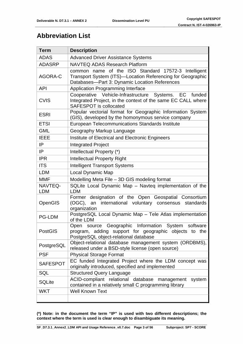
Abbreviation List Term Description ADAS Advanced Driver Assistance Systems ADASRP NAVTEQ ADAS Research Platform
AGORA-C common name of the ISO Standard 17572-3 Intelligent Transport System (ITS)—Location Referencing for Geographic Databases—Part 3: Dynamic Location References
API Application Programming Interface
CVIS Cooperative Vehicle-Infrastructure Systems. EC funded Integrated Project, in the context of the same EC CALL where SAFESPOT is collocated
ESRI Popular vectorial format for Geographic Information System (GIS), developed by the homonymous service company
ETSI European Telecommunications Standards Institute GML Geography Markup Language IEEE Institute of Electrical and Electronic Engineers IP Integrated Project IP Intellectual Property (*) IPR Intellectual Property Right ITS Intelligent Transport Systems LDM Local Dynamic Map MMF Modelling Meta File – 3D GIS modeling format NAVTEQ-LDM
SQLite Local Dynamic Map – Navteq implementation of the LDM
OpenGIS Former designation of the Open Geospatial Consortium (OGC), an international voluntary consensus standards organization
PG-LDM PostgreSQL Local Dynamic Map – Tele Atlas implementation of the LDM
PostGIS Open source Geographic Information System software program, adding support for geographic objects to the PostgreSQL object-relational database
PostgreSQL Object-relational database management system (ORDBMS), released under a BSD-style license (open source)
PSF Physical Storage Format
SAFESPOT EC funded Integrated Project where the LDM concept was originally introduced, specified and implemented
SQL Structured Query Language
SQLite ACID-compliant relational database management system contained in a relatively small C programming library
WKT Well Known Text
(*) Note: in the document the term “IP” is used with two different descriptions; the context where the term is used is clear enough to disambiguate its meaning.

Deliverable N. D7.3.1 – ANNEX 2 Dissemination Level PU Copyright SAFESPOT
Contract N. IST-4-026963-IP
SF_D7.3.1_Annex2_LDM API and Usage Reference_v0.7.doc Page 4 of 56 Subproject: SP7 - SCORE
Table of contents REVISION LOG......................................................................................................................... 2 ABBREVIATION LIST .............................................................................................................. 3 TABLE OF CONTENTS............................................................................................................ 4 LIST OF FIGURES.................................................................................................................... 5 LIST OF TABLES...................................................................................................................... 7 EXECUTIVE SUMMARY........................................................................................................... 8 1. INTRODUCTION ............................................................................................................ 9
1.1. Document structure...................................................................................................... 9 2. OVERVIEW OF THE LDM ............................................................................................. 9 3. OBJECT MODEL AND STRUCTURE OF THE LDM.................................................. 11
3.1. PG-LDM........................................................................................................................ 11 3.2. NAVTEQ-LDM.............................................................................................................. 14 3.3. Data Model Description.............................................................................................. 15
3.3.1. Staticfeatures......................................................................................................... 16 3.3.2. Movingobjects........................................................................................................ 23 3.3.3. Conceptualobjects ................................................................................................. 27 3.3.4. Relationships ......................................................................................................... 33 3.3.5. Others.................................................................................................................... 35
4. APPLICATION PROGRAMMING INTERFACE (API) ................................................. 36 4.1. Level 1 API................................................................................................................... 36 4.2. Level 2 API................................................................................................................... 41 4.3. API documentation ..................................................................................................... 46
5. STATUS OF KNOWN INTELLECTUAL PROPERTY RIGHTS (IPR) ......................... 55 6. CONCLUSIONS ........................................................................................................... 56 7. REFERENCES ............................................................................................................. 56 ADDENDUM............................................................................................................................ 56

Deliverable N. D7.3.1 – ANNEX 2 Dissemination Level PU Copyright SAFESPOT
Contract N. IST-4-026963-IP
SF_D7.3.1_Annex2_LDM API and Usage Reference_v0.7.doc Page 5 of 56 Subproject: SP7 - SCORE
List of Figures Figure 1 – The four layers of the LDM ..................................................................................................10 Figure 2 PG-LDM architecture in SAFESPOT ......................................................................................12 Figure 3 - PG-LDM architecture in CVIS ..............................................................................................12 Figure 4 - OpenJump visualisation of the Orbassano Test Track...........................................................14 Figure 5 - ADASRP server architecture .................................................................................................15 Figure 6 – colour labelling in the LDM tables .......................................................................................16 Figure 7 – arealandmarks: Spatial area object modelled by a single polygon ........................................17 Figure 8 – crossing: Spatial area object modelled by a single polygon, representing a crossing of a road
element with another transport mode, especially pedestrian, bicycle and railway .........................17 Figure 9 – crossingforreferencetracks: Static relationship between a crossing and a reference track ....17 Figure 10 – crossingsignal group: Static relationship between a signal group and a crossing ...............17 Figure 11 – detectionarea: Spatial area object modelled by a single polygon, representing the coverage
area of a sensor ...............................................................................................................................17 Figure 12 – detectionareaforcrossing: Static relationship between a detection area and a crossing.......18 Figure 13 – junction: Spatial point object modelled by a single point, representing a map database node
that bounds a road element or a ferry connection ...........................................................................18 Figure 14 – linelandmarks: Spatial linear object modelled by a single polyline ....................................19 Figure 15 – pointlandmarks: Point landmarks are painted signs, poles or other physical spots which are
used for positioning and detection purposes...................................................................................19 Figure 16 – referencetracks: Spatial linear object modelled by a single polyline, representing a
reference manoeuvre at an intersection from one road element connected to the intersection and a specific lane on that road element to another road element connected to the intersection and a specific lane on that road element ..................................................................................................19
Figure 17 – roadelement: Spatial linear object modelled by a single polyline, representing a map database edge that represents an elementary section of the road network......................................20
Figure 18 – roadintersection: Crossing and/or connection of two or more roads ...................................21 Figure 19 – sensor: Spatial point object modelled by a single point representing a sensor, a device
which detects or measures a physical property...............................................................................21 Figure 20 – sensorfordetectionarea: Static relationship between a sensor and a detection area .............21 Figure 21 – signalgroup: A logical object possessing a single state (see signalgroupstate) which is
displayed on one or more traffic light heads (see pointlandmarks) and applying to one or more lanes of a single road element entering a junction..........................................................................21
Figure 22 – signalgroupforreferencetrack: Static relationship between a single signalgroup and one or more referencetracks ......................................................................................................................22
Figure 23 – trafficsign: Spatial point object modelled by a single point representing a traffic sign or a variable message sign .....................................................................................................................22
Figure 24 – trafficsigninformation: Information content of a traffic sign, and relationship between this information and a traffic sign object...............................................................................................22
Figure 25 – egorsu: Information about the road side unit (RSU) that maintains the table .....................23 Figure 26 – rsu: Information about other road side units (RSUs) that is maintained by a road side unit,
or information about rod side units that is maintained by objects that are not a road side unit ......23 Figure 27 – egomotorvehicle: An ego motor vehicle unit. Mutually exclusive to the ego RSU; i.e. either
"egorsu" table is present in an LDM (SP2) or "egomotorvehicle" table is present (SP1), but not both. Only one entry in this table. The id of the egomotorvehicle is always 1...............................24
Figure 28 – motorvehicle: A non-ego motor vehicle unit. The value start at 2 as the 1 is reserved for the id of the egomotorvehicle ...............................................................................................................26
Figure 29 – uo: Unidentified (or partially identified) object. Includes VRU, other "living" objects etc. Attribute list essentially consists of the motorvehicle's dynamics attributes (describing its motion) and feattyp descriptor. In SAFESPOT, these types of objects will not have a VANET, hence all attributes have to be derived remotely............................................................................................26
Figure 30 – trailer: A trailer is connected to a tractor/truck/passenger car. It is not self-propelling. Hence its dynamics are governed by its hauling vehicle and its own characteristics .....................27
Figure 31 – accidenthotspot: Describes the results of statistical evaluation of historical accident data .28 Figure 32 – dynamicblackspot: Describes a spot where a risk of an incident (accident) is given. This
information is dynamic...................................................................................................................28 Figure 33 – dynamicreferencetrackattributes: Dynamic data provided associated with the static
reference track ................................................................................................................................28

Deliverable N. D7.3.1 – ANNEX 2 Dissemination Level PU Copyright SAFESPOT
Contract N. IST-4-026963-IP
SF_D7.3.1_Annex2_LDM API and Usage Reference_v0.7.doc Page 6 of 56 Subproject: SP7 - SCORE
Figure 34 – dynamicroadelementattribute: Dynamic attributes that can be associated to a road element - in case the information should be provided per lane or per vehicle type several entries for a road element can be specified.................................................................................................................28
Figure 35 – dynamicsensorattributes: Dynamic data provided associated with the sensor ....................29 Figure 36 – dynamicsensorstatus: Dynamic Sensor Status information.................................................29 Figure 37 – dynamictrafficsign: This feature represents a moving traffic sign (used for road works for
example) or a sub traffic sign display on a VMS ...........................................................................29 Figure 38 – dynamictrafficsigninformation: Identification of the dynamic traffic sign the dynamic
traffic sign information belongs to .................................................................................................29 Figure 39 – environmentalevent: This table provides measure whether information which are given in
general by weatherstations..............................................................................................................30 Figure 40 – fcdevent: Floating Car Data events .....................................................................................30 Figure 41 – meteodetection: Detected weather events ...........................................................................31 Figure 42 – roadconditionmeasurement: Measurement of the Road Condition (currently used only for
the snow thickness).........................................................................................................................31 Figure 43 – roadconditionevent: Detected road conditions as defined in the roadcondevent.................31 Figure 44 – signalgroupstate: Contains the dynamic attributes of a (static) signalgroup .......................32 Figure 45 – trafficevent: Externally generated message coming from safetycentre ...............................32 Figure 46 – trafficobject: Traffic state information for a road element ..................................................33 Figure 47 – dynamicreferencetrack: recommended path when the road becomes part of a black-spot..33 Figure 48 – alongroadelement: Map matched position of a motor vehicle or other moving object.
Explicit storage of moving object-road relationship. The field ID is the identifier of the given relationship. This is mainly for consistency (i.e. that all tables have an "id" field). Queries concerning this table will often/mostly/always(?) be given through the vehicle and/or road element ids. ..................................................................................................................................................33
Figure 49 – conceptualalongroadelement: m to n relationship between roadelements and conceptual objects. The field ID is the identifier of the given relationship. This is mainly for consistency (i.e. that all tables have an "id" field). Queries concerning this table will often/mostly/always(?) be given through the conceptualobject_id and/or road_element_id ....................................................34
Figure 50 – trajectory: Contains the possible trajectories of moving objects. A single moving object can have multiple trajectories. A trajectory is the predicted future path of the moving object. This may consider the object's current dynamics (position, velocity, yaw rate etc.), the static road geometry (possibly also reference tracks) and possibly even other indicators of driver intention (turn indicator status etc.). The attributes here were derived from the LDM EAP file, as well as FuturePath struct in SRresult.h from ICCS (SP1) ..........................................................................34
Figure 51 – gatewaycommunication: to ease communication between e.g. safetycentre-gateway and dynamic black spot calculation allow Datareceiver to just save content of message in form of string into this table. Using notification, interested parties can handle the data without polling....35
Figure 52 – messagebox: container for rsu-hmi messages. See also SP7 Data format and messages doc HMI MessageFromVanet ..........................................................................................................35
Figure 53 – LDM-API classes, structs, unions and interfaces, with a brief related description .............46 Figure 54 – LDM-API class member functions, (1 of 22)......................................................................46 Figure 55 – LDM-API class member functions, (2 of 22)......................................................................47 Figure 56 – LDM-API class member functions, (3 of 22)......................................................................47 Figure 57 – LDM-API class member functions, (4 of 22)......................................................................47 Figure 58 – LDM-API class member functions, (5 of 22)......................................................................48 Figure 59 – LDM-API class member functions, (6 of 21)......................................................................48 Figure 60 – LDM-API class member functions, (7 of 22)......................................................................48 Figure 61 – LDM-API class member functions, (8 of 22)......................................................................50 Figure 62 – LDM-API class member functions, (9 of 22)......................................................................50 Figure 63 – LDM-API class member functions, (10 of 22)....................................................................50 Figure 64 – LDM-API class member functions, (11 of 22)....................................................................50 Figure 65 – LDM-API class member functions, (12 of 22)....................................................................51 Figure 66 – LDM-API class member functions, (13 of 22)....................................................................51 Figure 67 – LDM-API class member functions, (14 of 22)....................................................................51 Figure 68 – LDM-API class member functions, (15 of 22)....................................................................52 Figure 69 – LDM-API class member functions, (16 of 22)....................................................................52 Figure 70 – LDM-API class member functions, (17 of 22)....................................................................52 Figure 71 – LDM-API class member functions, (18 of 22)....................................................................53 Figure 72 – LDM-API class member functions, (19 of 22)....................................................................53 Figure 73 – LDM-API class member functions, (20 of 22)....................................................................53

Deliverable N. D7.3.1 – ANNEX 2 Dissemination Level PU Copyright SAFESPOT
Contract N. IST-4-026963-IP
SF_D7.3.1_Annex2_LDM API and Usage Reference_v0.7.doc Page 7 of 56 Subproject: SP7 - SCORE
Figure 74 – LDM-API class member functions, (21 of 22)....................................................................53 Figure 75 – LDM-API class member functions, (22 of 22)....................................................................54
List of Tables Table 1 - LDM Concrete Classes ...........................................................................................................16

Deliverable N. D7.3.1 – ANNEX 2 Dissemination Level PU Copyright SAFESPOT
Contract N. IST-4-026963-IP
SF_D7.3.1_Annex2_LDM API and Usage Reference_v0.7.doc Page 8 of 56 Subproject: SP7 - SCORE
EXECUTIVE SUMMARY The document describes the LDM (Structure of the database, Object Model, API) from the perspective of the final users. Within the SAFESPOT IP, these users are the subprojects in charge to develop the vehicle based and the infrastructure based applications, together with the subprojects where the vehicle and the infrastructure platforms are in charge to fill in and maintain the consistence of the LDM database. Outside SAFESPOT, the users of the LDM are all the individuals and companies who intend to adopt this key achievement of SAFESPOT as a building block for the consistent and solid representation of the environment and the scenarios where their applications will work (typically in the domains of ITS, ADAS and Cooperative Systems). In this respect, information related to the structure and the object model of the LDM is needed to the final users for getting a proper understanding of “what is” the LDM, where the Application Programming Interface is practically needed to “make the proper usage” of it. SAFESPOT modules access the LDM through this specific and predefined interface. The LDM API is divided into two parts: the level 1 functions, providing flexible, generic access to the LDM through low-level operations and the level 2 functions, designed to achieve a specialised access to the database. The present annex of the D7.3.1 deliverable is released in a public form in order:
1. to describe the concept and the content of the LDM database; 2. to enable and to promote the usage of the LDM externally to the
SAFESPOT IP; 3. to start the standardization activities (towards the IEEE, ETSI or other
possible standardization bodies); 4. to ensure a proper level of public information is available outside of the
SAFESPOT domain, in order for the original contributors (to the definition, specification and implementation of the SAFESPOT LDM) are properly acknowledged for their work on the subject.

Deliverable N. D7.3.1 – ANNEX 2 Dissemination Level PU Copyright SAFESPOT
Contract N. IST-4-026963-IP
SF_D7.3.1_Annex2_LDM API and Usage Reference_v0.7.doc Page 9 of 56 Subproject: SP7 - SCORE
1. Introduction The local dynamic map, which is constructed on top of the digital map database, is considered one of the essential elements of future safety oriented cooperative systems in general, and of the SAFESPOT system in particular. In the LDM, the road geometry from a standard digital map is integrated with the information collected by vehicles and the infrastructure. It provides a real-time mapping of relevant static, temporary and dynamic infrastructure and non-infrastructure elements and objects around the system that is maintaining its consistence. The LDM is a highly dynamic data store with a relation to the road network. It enables storage and updating of objects including type, position and other characteristics, and retrieval of selected information for further processing and situation analysis, like calculation of trajectories, and detection of hazardous obstacles and potential conflicts with other road users. If the object that maintains the LDM is moving, the map window is moving as well, with the object as its center point.
1.1. Document structure Chapter 2 gives some preliminary explanations and descriptions about the LDM, introducing the four conceptual layers composing it; chapter 3 details the object model and the structure of the LDM, with reference to the last version of the LDM implementation, as built in the SAFESPOT project (release 10.0.12 of the LDM data model). Chapter 4 contains information needed for the practical usage from the users perspective of the LDM, detailing the API adopted for the access, the reading and the updating of its content. Chapter 5 is included to make explicit the underlying intellectual property in terms of background and foreground knowledge provided by the companies who defined conceptually, designed and implemented the LDM in the SAFESPOT project. Chapter 6 contains some conclusions related to the material contained in the present document.
2. Overview of the LDM The LDM can be considered as an innovative database where to represent, as four different conceptual layers, from bottom to top:
• layer 1 - the static (and preferably ADAS enhanced) map database • layer 2 - additional static information not present in the standard map
database • layer 3 - temporary and dynamic information (e.g. weather and traffic
conditions) • layer 4 - dynamic and highly dynamic objects
The bottom layer is the static map as used today in navigation systems, possibly with enhanced geometry and attributes (ADAS specification). The second layer is not very different from the bottom layer: it contains static information (mainly attributes) that is not yet contained in the standard map database, but may be in the future. The third layer is for temporary and dynamic information, for instance the information related to traffic and
Deliverable N. D7.3.1 – ANNEX 2 Dissemination Level PU Copyright SAFESPOT
Contract N. IST-4-026963-IP
SF_D7.3.1_Annex2_LDM API and Usage Reference_v0.7.doc Page 10 of 56 Subproject: SP7 - SCORE
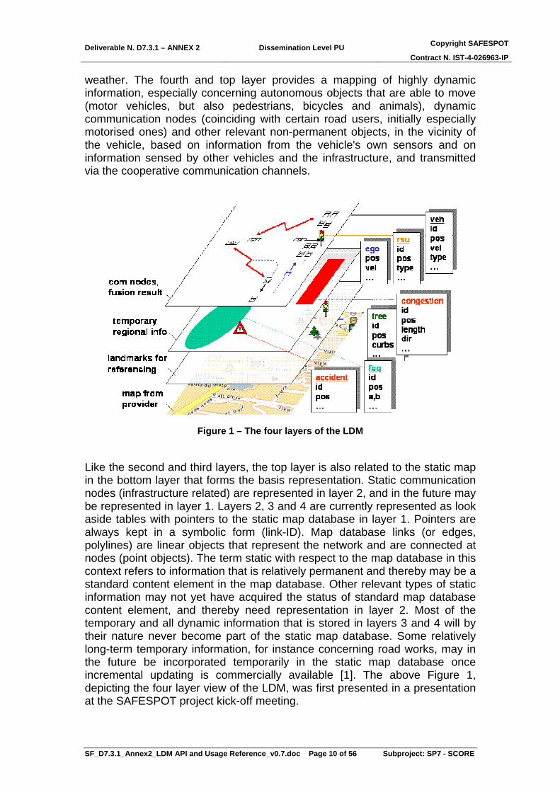
weather. The fourth and top layer provides a mapping of highly dynamic information, especially concerning autonomous objects that are able to move (motor vehicles, but also pedestrians, bicycles and animals), dynamic communication nodes (coinciding with certain road users, initially especially motorised ones) and other relevant non-permanent objects, in the vicinity of the vehicle, based on information from the vehicle's own sensors and on information sensed by other vehicles and the infrastructure, and transmitted via the cooperative communication channels.
Figure 1 – The four layers of the LDM
Like the second and third layers, the top layer is also related to the static map in the bottom layer that forms the basis representation. Static communication nodes (infrastructure related) are represented in layer 2, and in the future may be represented in layer 1. Layers 2, 3 and 4 are currently represented as look aside tables with pointers to the static map database in layer 1. Pointers are always kept in a symbolic form (link-ID). Map database links (or edges, polylines) are linear objects that represent the network and are connected at nodes (point objects). The term static with respect to the map database in this context refers to information that is relatively permanent and thereby may be a standard content element in the map database. Other relevant types of static information may not yet have acquired the status of standard map database content element, and thereby need representation in layer 2. Most of the temporary and all dynamic information that is stored in layers 3 and 4 will by their nature never become part of the static map database. Some relatively long-term temporary information, for instance concerning road works, may in the future be incorporated temporarily in the static map database once incremental updating is commercially available [1]. The above Figure 1, depicting the four layer view of the LDM, was first presented in a presentation at the SAFESPOT project kick-off meeting.

Deliverable N. D7.3.1 – ANNEX 2 Dissemination Level PU Copyright SAFESPOT
Contract N. IST-4-026963-IP
SF_D7.3.1_Annex2_LDM API and Usage Reference_v0.7.doc Page 11 of 56 Subproject: SP7 - SCORE
3. Object Model and Structure of the LDM The object model of the LDM has a hierarchical structure using associations between classes to describe their relationships. Due to the computing and bandwidth limitations in the SAFESPOT platforms, a fully object-oriented implementation was not deemed to be feasible. The overhead of transferring objects over the network, maintaining synchronicity between the objects on the various platforms as well as the relatively low number of object-specific “methods” to be provided by the LDM (with the prominent exception of spatial methods) all contributed to this conclusion. Consequently, the LDM uses a more traditional, relational database approach and only implements a sub-set of the specified classes – the concrete classes. From the users’ point of view, concrete classes can be seen as separate tables in the database, with the attributes as columns and each new realization of an object as a row. Two different implementations are available linked to the two map providers of static maps, Tele Atlas (PG-LDM) and NAVTEQ (NAVTEQ-LDM). The implementations are described in the following subchapters.
3.1. PG-LDM In SAFESPOT the PG-LDM is based on a PostgreSQL database using the PostGIS extension suitable for spatial static and dynamic data handling. Level 1 and Level 2 API in C++ are provided for data access and lookup of geospatial data as well as geospatial situation analysis. For the PG-LDM implementation the remote clients can access the corresponding sources via the Ethernet network. Clients as well as servers are supported in C++ under Windows and Linux. PostgreSQL, an open source relational database system available for multiple operating systems like Windows and Linux is used as the datastore layer of the PG-LDM. It is SQL compliant and offers a stable platform for developing databases. It has obtained a high level of acceptance and a large number of users world-wide. It claims to have high reliability, scalability and speed. Importantly, the PostGIS add-on provides support for geographic objects following the OpenGIS Simple Feature Specification. PostgreSQL-PostGIS provides an open source spatial database with support for geographic data objects as well as spatial functionality. Considering the spatial context of (almost) all objects in the LDM, this built-in spatial support is seen to be attractive.

Deliverable N. D7.3.1 – ANNEX 2 Dissemination Level PU Copyright SAFESPOT
Contract N. IST-4-026963-IP
SF_D7.3.1_Annex2_LDM API and Usage Reference_v0.7.doc Page 12 of 56 Subproject: SP7 - SCORE
Figure 2 PG-LDM architecture in SAFESPOT
Supporting cross-project activities to CVIS the PG-LDM has been further developed with a slightly different configuration. In CVIS, the PG-LDM bundle is an extension of the Tele Atlas Automotive Research Platform which provides further CVIS related functions for AGORA-C, map matching and routing. For all platforms Tele Atlas provides the map data files for PostgreSQL databases and a non-standard PSF.
Figure 3 - PG-LDM architecture in CVIS
The PG-LDM is implemented by Bosch and Tele Atlas.

Deliverable N. D7.3.1 – ANNEX 2 Dissemination Level PU Copyright SAFESPOT
Contract N. IST-4-026963-IP
SF_D7.3.1_Annex2_LDM API and Usage Reference_v0.7.doc Page 13 of 56 Subproject: SP7 - SCORE
The delivered SAFESPOT version of the PG-LDM-API bundle in C++ contains the following components:
• example_code.zip – contains a Visual Express project with a short example for using “intersects”, “buffer” and notification
• PG-LDM-API_1_9_10_documentation.zip – API specification in html, double click on “index.html”
• ldm.ini – an example for the ini-file, needed to setup a database connection, see API-documentation for “DBConn”
• CW_R1_9_10.zip – contains the include files and the compiled libraries for Windows
• CL_R1_9_10.zip – contains the include files and the compiled libraries for Linux
• SF_SP3_Guidelines_for_PG-LDM_v1.5.doc – an installation manual for setting up the environment for PG-LDM
For the Java PG-LDM-API, the following components are provided to CVIS as part of the collaboration with SAFESPOT:
• code_examples – provided on the CVIS portal WIKI page • html documentation – created using javadoc • LDM data model – list of the table structure • Java OSGI PG-LDM bundle – as jar-file containing the PG-LDM-API and
application PostgreSQL provides administration monitoring support via pgAdminIII. pgAdminIII is an open source administration and development platform for PostgreSQL. As visualization and analysis software, OpenJump has been selected for the PG-LDM. OpenJump is developed within an umbrella project called the JUMP Pilot Project and distributed under the GPL license. It is an open source GIS (geo-information system) software implemented in Java based on JUMP GIS by Vivid Solutions. Due to the usage of Java, OpenJump should work on any operating system that runs Java 1.5 or later. For SAFESPOT that means OpenJump can be used on both Windows and Linux platforms. Within SAFESPOT there will be only a very small subset of OpenJump functionalities and features in use, mainly as a demo viewer and data analysing tool. The most used functionalities are:
• Import database (LDM) content, especially the spatial data for visualisation (see Figure 4)
• Advanced attribute query which can highlight the result objects • Spatial queries are supported, e.g. intersection of two objects, buffer,
convexhull • Zoom to an user defined map scale • Enhanced set of selection tools • Save database (LDM) content in different standard format, e.g. GML
(Geography Markup Language), WKT (Well Known Text), ESRI shapefile

Deliverable N. D7.3.1 – ANNEX 2 Dissemination Level PU Copyright SAFESPOT
Contract N. IST-4-026963-IP
SF_D7.3.1_Annex2_LDM API and Usage Reference_v0.7.doc Page 14 of 56 Subproject: SP7 - SCORE
Figure 4 - OpenJump visualisation of the Orbassano Test Track
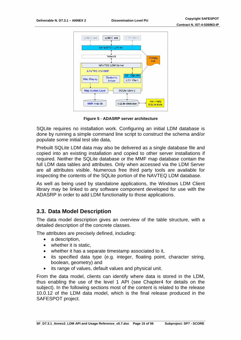
3.2. NAVTEQ-LDM As with the PG-LDM, the NAVTEQ LDM client delivery is a single static library file (ldmapi.lib for Windows XP or ldmapi.a for Linux) and associated header files that define the API classes and methods. However, the Windows based LDM Server is implemented as a component (referred to as a plug-in) of the NAVTEQ ADAS Research Platform (ADASRP). This application platform provides the server with access to both a static map database (in the MMF physical storage format) and an SQLite dynamically updateable embedded database. The LDM Server provides a single interface for accessing data from either of these two data sources, and for writing data to the SQLite database. The Linux based LDM Server is a standalone service that provides this same LDM functionality. Both implementations communicate equally with either the Windows or Linux client library.
Deliverable N. D7.3.1 – ANNEX 2 Dissemination Level PU Copyright SAFESPOT
Contract N. IST-4-026963-IP
SF_D7.3.1_Annex2_LDM API and Usage Reference_v0.7.doc Page 15 of 56 Subproject: SP7 - SCORE
Figure 5 - ADASRP server architecture
SQLite requires no installation work. Configuring an initial LDM database is done by running a simple command line script to construct the schema and/or populate some initial test site data, Prebuilt SQLite LDM data may also be delivered as a single database file and copied into an existing installation and copied to other server installations if required. Neither the SQLite database or the MMF map database contain the full LDM data tables and attributes. Only when accessed via the LDM Server are all attributes visible. Numerous free third party tools are available for inspecting the contents of the SQLite portion of the NAVTEQ LDM database. As well as being used by standalone applications, the Windows LDM Client library may be linked to any software component developed for use with the ADASRP in order to add LDM functionality to those applications.
3.3. Data Model Description The data model description gives an overview of the table structure, with a detailed description of the concrete classes. The attributes are precisely defined, including:
• a description, • whether it is static, • whether it has a separate timestamp associated to it, • its specified data type (e.g. integer, floating point, character string,
boolean, geometry) and • its range of values, default values and physical unit.
From the data model, clients can identify where data is stored in the LDM, thus enabling the use of the level 1 API (see Chapter4 for details on the subject). In the following sections most of the content is related to the release 10.0.12 of the LDM data model, which is the final release produced in the SAFESPOT project.

Deliverable N. D7.3.1 – ANNEX 2 Dissemination Level PU Copyright SAFESPOT
Contract N. IST-4-026963-IP
SF_D7.3.1_Annex2_LDM API and Usage Reference_v0.7.doc Page 16 of 56 Subproject: SP7 - SCORE
Table 1 - LDM Concrete Classes
Figure 6 – colour labelling in the LDM tables
3.3.1. Staticfeatures The static objects represent the information in layers 1 and 2 of the LDM. This concerns information that is today in the static map database (layer 1), and information that has a similar character, but is not (or not yet) part of the static map database (layer 2). Over time the specification of the static map database evolves, and some information that is today in layer 2 may in the future be incorporated in the static map database. In the model of the LDM the parent class of all static objects is Staticfeatures. This term is chosen as it is used in GDF, where the “feature” is defined as "the database representation of a real world object". In the LDM model the class Staticfeatures is an abstract subclass of the class WorldObject.

Deliverable N. D7.3.1 – ANNEX 2 Dissemination Level PU Copyright SAFESPOT
Contract N. IST-4-026963-IP
SF_D7.3.1_Annex2_LDM API and Usage Reference_v0.7.doc Page 17 of 56 Subproject: SP7 - SCORE
Figure 7 – arealandmarks: Spatial area object modelled by a single polygon
Figure 8 – crossing: Spatial area object modelled by a single polygon, representing a crossing of a road element with another transport mode, especially pedestrian, bicycle
and railway
Figure 9 – crossingforreferencetracks: Static relationship between a crossing and a reference track
Figure 10 – crossingsignal group: Static relationship between a signal group and a crossing
Figure 11 – detectionarea: Spatial area object modelled by a single polygon, representing the coverage area of a sensor

Deliverable N. D7.3.1 – ANNEX 2 Dissemination Level PU Copyright SAFESPOT
Contract N. IST-4-026963-IP
SF_D7.3.1_Annex2_LDM API and Usage Reference_v0.7.doc Page 18 of 56 Subproject: SP7 - SCORE
Figure 12 – detectionareaforcrossing: Static relationship between a detection area and a crossing
Figure 13 – junction: Spatial point object modelled by a single point, representing a map database node that bounds a road element or a ferry connection

Deliverable N. D7.3.1 – ANNEX 2 Dissemination Level PU Copyright SAFESPOT
Contract N. IST-4-026963-IP
SF_D7.3.1_Annex2_LDM API and Usage Reference_v0.7.doc Page 19 of 56 Subproject: SP7 - SCORE
Figure 14 – linelandmarks: Spatial linear object modelled by a single polyline
Figure 15 – pointlandmarks: Point landmarks are painted signs, poles or other physical spots which are used for positioning and detection purposes
Figure 16 – referencetracks: Spatial linear object modelled by a single polyline, representing a reference manoeuvre at an intersection from one road element
connected to the intersection and a specific lane on that road element to another road element connected to the intersection and a specific lane on that road element

Deliverable N. D7.3.1 – ANNEX 2 Dissemination Level PU Copyright SAFESPOT
Contract N. IST-4-026963-IP
SF_D7.3.1_Annex2_LDM API and Usage Reference_v0.7.doc Page 20 of 56 Subproject: SP7 - SCORE
Figure 17 – roadelement: Spatial linear object modelled by a single polyline, representing a map database edge that represents an elementary section of the road
network

Deliverable N. D7.3.1 – ANNEX 2 Dissemination Level PU Copyright SAFESPOT
Contract N. IST-4-026963-IP
SF_D7.3.1_Annex2_LDM API and Usage Reference_v0.7.doc Page 21 of 56 Subproject: SP7 - SCORE
Figure 18 – roadintersection: Crossing and/or connection of two or more roads
Figure 19 – sensor: Spatial point object modelled by a single point representing a sensor, a device which detects or measures a physical property
Figure 20 – sensorfordetectionarea: Static relationship between a sensor and a detection area
Figure 21 – signalgroup: A logical object possessing a single state (see signalgroupstate) which is displayed on one or more traffic light heads (see

Deliverable N. D7.3.1 – ANNEX 2 Dissemination Level PU Copyright SAFESPOT
Contract N. IST-4-026963-IP
SF_D7.3.1_Annex2_LDM API and Usage Reference_v0.7.doc Page 22 of 56 Subproject: SP7 - SCORE
pointlandmarks) and applying to one or more lanes of a single road element entering a junction
Figure 22 – signalgroupforreferencetrack: Static relationship between a single signalgroup and one or more referencetracks
Figure 23 – trafficsign: Spatial point object modelled by a single point representing a
traffic sign or a variable message sign
Figure 24 – trafficsigninformation: Information content of a traffic sign, and
relationship between this information and a traffic sign object

Deliverable N. D7.3.1 – ANNEX 2 Dissemination Level PU Copyright SAFESPOT
Contract N. IST-4-026963-IP
SF_D7.3.1_Annex2_LDM API and Usage Reference_v0.7.doc Page 23 of 56 Subproject: SP7 - SCORE
Figure 25 – egorsu: Information about the road side unit (RSU) that maintains the table
Figure 26 – rsu: Information about other road side units (RSUs) that is maintained by a road side unit, or information about rod side units that is maintained by objects that
are not a road side unit
3.3.2. Movingobjects The class Movingobjects is a subclass of DynamicObject, and is the basic class to represent any road user. Four subclasses are defined: EgoMotorVehicle, MotorVehicle, UnidentifiedObject and Trailer. Each moving object is characterised by one MotionState and it may have one or more Trajectory objects. Typically the moving objects represent the information in layer 4 of the LDM.

Deliverable N. D7.3.1 – ANNEX 2 Dissemination Level PU Copyright SAFESPOT
Contract N. IST-4-026963-IP
SF_D7.3.1_Annex2_LDM API and Usage Reference_v0.7.doc Page 24 of 56 Subproject: SP7 - SCORE
Figure 27 – egomotorvehicle: An ego motor vehicle unit. Mutually exclusive to the ego RSU; i.e. either "egorsu" table is present in an LDM (SP2) or "egomotorvehicle" table is present (SP1), but not both. Only one entry in this table. The id of the egomotorvehicle
is always 1

Deliverable N. D7.3.1 – ANNEX 2 Dissemination Level PU Copyright SAFESPOT
Contract N. IST-4-026963-IP
SF_D7.3.1_Annex2_LDM API and Usage Reference_v0.7.doc Page 25 of 56 Subproject: SP7 - SCORE

Deliverable N. D7.3.1 – ANNEX 2 Dissemination Level PU Copyright SAFESPOT
Contract N. IST-4-026963-IP
SF_D7.3.1_Annex2_LDM API and Usage Reference_v0.7.doc Page 26 of 56 Subproject: SP7 - SCORE
Figure 28 – motorvehicle: A non-ego motor vehicle unit. The value start at 2 as the 1 is reserved for the id of the egomotorvehicle
Figure 29 – uo: Unidentified (or partially identified) object. Includes VRU, other "living" objects etc. Attribute list essentially consists of the motorvehicle's dynamics attributes
(describing its motion) and feattyp descriptor. In SAFESPOT, these types of objects will not have a VANET, hence all attributes have to be derived remotely

Deliverable N. D7.3.1 – ANNEX 2 Dissemination Level PU Copyright SAFESPOT
Contract N. IST-4-026963-IP
SF_D7.3.1_Annex2_LDM API and Usage Reference_v0.7.doc Page 27 of 56 Subproject: SP7 - SCORE
Figure 30 – trailer: A trailer is connected to a tractor/truck/passenger car. It is not self-
propelling. Hence its dynamics are governed by its hauling vehicle and its own characteristics
3.3.3. Conceptualobjects
The class Conceptualobjects is a subclass of DynamicObject, and is the basic class to represent any traffic and environmental events. Seventeen subclasses are defined: AccidentHotSpot, DynamicBlackSpot, DynamicReferencetrackAttributes, DynamicRoadelementAttribute, DynamicSensorAttributes, DynamicSensorStatus, DynamicTrafficSign, DynamicTrafficsignInformation, EnvironmentalEvent, FcdEvent, MeteoDetection, RoadConditionEvent, RoadConditionMeasurement, SignalGroupState, TrafficEvent, TrafficObject, DynamicReferenceTrack. Typically the conceptual objects represent the information in the layer 3 of the LDM.

Deliverable N. D7.3.1 – ANNEX 2 Dissemination Level PU Copyright SAFESPOT
Contract N. IST-4-026963-IP
SF_D7.3.1_Annex2_LDM API and Usage Reference_v0.7.doc Page 28 of 56 Subproject: SP7 - SCORE
Figure 31 – accidenthotspot: Describes the results of statistical evaluation of historical accident data
Figure 32 – dynamicblackspot: Describes a spot where a risk of an incident (accident)
is given. This information is dynamic
Figure 33 – dynamicreferencetrackattributes: Dynamic data provided associated with
the static reference track
Figure 34 – dynamicroadelementattribute: Dynamic attributes that can be associated to
a road element - in case the information should be provided per lane or per vehicle type several entries for a road element can be specified

Deliverable N. D7.3.1 – ANNEX 2 Dissemination Level PU Copyright SAFESPOT
Contract N. IST-4-026963-IP
SF_D7.3.1_Annex2_LDM API and Usage Reference_v0.7.doc Page 29 of 56 Subproject: SP7 - SCORE
Figure 35 – dynamicsensorattributes: Dynamic data provided associated with the sensor
Figure 36 – dynamicsensorstatus: Dynamic Sensor Status information
Figure 37 – dynamictrafficsign: This feature represents a moving traffic sign (used for
road works for example) or a sub traffic sign display on a VMS
Figure 38 – dynamictrafficsigninformation: Identification of the dynamic traffic sign the
dynamic traffic sign information belongs to

Deliverable N. D7.3.1 – ANNEX 2 Dissemination Level PU Copyright SAFESPOT
Contract N. IST-4-026963-IP
SF_D7.3.1_Annex2_LDM API and Usage Reference_v0.7.doc Page 30 of 56 Subproject: SP7 - SCORE
Figure 39 – environmentalevent: This table provides measure whether information
which are given in general by weatherstations
Figure 40 – fcdevent: Floating Car Data events

Deliverable N. D7.3.1 – ANNEX 2 Dissemination Level PU Copyright SAFESPOT
Contract N. IST-4-026963-IP
SF_D7.3.1_Annex2_LDM API and Usage Reference_v0.7.doc Page 31 of 56 Subproject: SP7 - SCORE
Figure 41 – meteodetection: Detected weather events
Figure 42 – roadconditionmeasurement: Measurement of the Road Condition (currently used only for the snow thickness)
Figure 43 – roadconditionevent: Detected road conditions as defined in the
roadcondevent

Deliverable N. D7.3.1 – ANNEX 2 Dissemination Level PU Copyright SAFESPOT
Contract N. IST-4-026963-IP
SF_D7.3.1_Annex2_LDM API and Usage Reference_v0.7.doc Page 32 of 56 Subproject: SP7 - SCORE
Figure 44 – signalgroupstate: Contains the dynamic attributes of a (static) signalgroup
Figure 45 – trafficevent: Externally generated message coming from safetycentre

Deliverable N. D7.3.1 – ANNEX 2 Dissemination Level PU Copyright SAFESPOT
Contract N. IST-4-026963-IP
SF_D7.3.1_Annex2_LDM API and Usage Reference_v0.7.doc Page 33 of 56 Subproject: SP7 - SCORE
Figure 46 – trafficobject: Traffic state information for a road element
Figure 47 – dynamicreferencetrack: recommended path when the road becomes part of
a black-spot
3.3.4. Relationships The class Relationship is used to instantiate specific relationships among other objects (dynamic or static) in the World Object. Three subclasses are defined: AlongRoadElement, ConceptualAlongRoadElement and Trajectory.
Figure 48 – alongroadelement: Map matched position of a motor vehicle or other
moving object. Explicit storage of moving object-road relationship. The field ID is the identifier of the given relationship. This is mainly for consistency (i.e. that all tables
have an "id" field). Queries concerning this table will often/mostly/always(?) be given through the vehicle and/or road element ids.

Deliverable N. D7.3.1 – ANNEX 2 Dissemination Level PU Copyright SAFESPOT
Contract N. IST-4-026963-IP
SF_D7.3.1_Annex2_LDM API and Usage Reference_v0.7.doc Page 34 of 56 Subproject: SP7 - SCORE
Figure 49 – conceptualalongroadelement: m to n relationship between roadelements and conceptual objects. The field ID is the identifier of the given relationship. This is mainly for consistency (i.e. that all tables have an "id" field). Queries concerning this
table will often/mostly/always(?) be given through the conceptualobject_id and/or road_element_id
Figure 50 – trajectory: Contains the possible trajectories of moving objects. A single moving object can have multiple trajectories. A trajectory is the predicted future path
of the moving object. This may consider the object's current dynamics (position, velocity, yaw rate etc.), the static road geometry (possibly also reference tracks) and
possibly even other indicators of driver intention (turn indicator status etc.). The attributes here were derived from the LDM EAP file, as well as FuturePath struct in
SRresult.h from ICCS (SP1)

Deliverable N. D7.3.1 – ANNEX 2 Dissemination Level PU Copyright SAFESPOT
Contract N. IST-4-026963-IP
SF_D7.3.1_Annex2_LDM API and Usage Reference_v0.7.doc Page 35 of 56 Subproject: SP7 - SCORE
3.3.5. Others The class Others is used to instantiate other specific objects (dynamic or static) in the World Object. Two subclasses are defined: GatewayCommunicaton and MessageBox.
Figure 51 – gatewaycommunication: to ease communication between e.g. safetycentre-gateway and dynamic black spot calculation allow Datareceiver to just save content of
message in form of string into this table. Using notification, interested parties can handle the data without polling
Figure 52 – messagebox: container for rsu-hmi messages. See also SP7 Data format
and messages doc HMI MessageFromVanet

Deliverable N. D7.3.1 – ANNEX 2 Dissemination Level PU Copyright SAFESPOT
Contract N. IST-4-026963-IP
SF_D7.3.1_Annex2_LDM API and Usage Reference_v0.7.doc Page 36 of 56 Subproject: SP7 - SCORE
4. Application Programming Interface (API) The LDM software consists of:
• libraries that are used by clients to connect to and access the server • runnable modules (including initialisation and configuration files) that
implement the LDM server • map data files containing the static object information for the relevant
test sites. The connection class (DBConn) establishes a communication channel between the client application and the LDM Server, regardless of the physical location of the server itself. The DBConn is initialized (or created) using a configuration file with a standard INI format that provides enough information for the client library to locate the LDM Server. Given a valid configuration file, the DBConn is used to open() and close() a connection to the LDM Server and determine the schema version used by the server. A connection to a server with an incompatible schema version will not be allowed. In order to get the information which schema version can be used for the release, the function getSchemaVersion() has been provided. Once successfully open, the DBConn object may be passed to any number of instances of the Level 1 or Level 2 APIs. SAFESPOT modules access the LDM through a defined interface. The LDM API is divided into two parts:
• Level 1 functions which provide flexible, generic access to the LDM through low-level operations
• Level 2 functions designed to provide specialised access to the database.
4.1. Level 1 API The Level 1 API provides a very generic and flexible API that draws on SQL syntax. It essentially maps the query directly (i.e. without syntactic or semantic checking) to an SQL statement that is run on the LDM server. Due to its simplicity, and the fact that both LDM implementations utilise an SQL DBMS, it has been relatively quick and easy to implement. A common feature of the Level 1 API is that input and output arguments are provided as strings. This emphasises the flexible nature of these methods. The same method can be used regardless of the type or number of logical arguments the query requires. Strings arguments can be used to represent single values or lists of numeric quantities, boolean flags or character strings. From a Level 1 query’s string arguments, the corresponding SQL statement can then be formed by concatenating the input string arguments with relevant SQL keywords (possibly with basic string operations to separate list elements). Clearly, without the syntactic or semantic checking of the arguments, this approach is unable to prevent/catch incorrectly formed queries from being made by clients to the LDM server. Therefore, it must be used with care by the users’ modules. The Level 1 API consists of methods that can be grouped into the following categories:

Deliverable N. D7.3.1 – ANNEX 2 Dissemination Level PU Copyright SAFESPOT
Contract N. IST-4-026963-IP
SF_D7.3.1_Annex2_LDM API and Usage Reference_v0.7.doc Page 37 of 56 Subproject: SP7 - SCORE
• data modification: insert, update, delete. These operations modify the contents of the LDM – i.e. they form the T-API.
• attribute recall: query. This generic method provides attribute values stored in the LDM (it is mapped to a SELECT SQL statement).
• spatial feature generation: e.g. intersection, geomUnion, difference, envelope, convexhull, buffer, boundary, centroid. New geometries are generated by these methods based on one or more existing or explicitly defined geometries.
• spatial predicates: e.g. intersects, contains, equals. Spatial tests on the relationships between the geometries of two objects or on the properties of a single geometry.
• spatial metering: e.g. distance, length, area. Metrics of a geometry or between two geometries.
• return value processing: next, previous, first, last, size, value. These functions do not access the LDM, rather they allow the processing of the results of the operations listed above.
• transaction handling: begin, commit, rollback. These functions allow a propose transaction handling to guarantee that all corresponding LDM tables are updated in a consistent way.
As the level 1 API is low-level, in addition to the software functions provided, users should be aware of the object model used by the LDM. Input parameters For simplicity and to enable flexibility, the input parameters of the above functions are generally strings. Often, an input argument may consist of a list of multiple logical quantities. In these cases, the individual elements of the list are comma separated. White space is ignored. As already stated, developers should be aware that the input arguments are not parsed to ensure correctness. In most cases, the string arguments are copied verbatim into a command string that is submitted to the LDM database server. Common types of inputs include:
• Object type list - A comma separated list of object types (tables in the LDM) as defined in the LDM object model, e.g. "motorvehicle, environmentalevent". All Level 1 queries have an object type list as their first argument
• Attribute names - Comma separated list of attribute names (columns in an LDM table), e.g. "id, speed"
• Attribute values - Comma separated list of attribute values • Equality and inequality conditions, =,!=,<,<=,>,>= • Conditions - An "AND" separated list of equality or inequality clauses.
Each clause should have the form <attribute name> <equality/inequality> <attribute value>
• ID conditions - A specialised form of Conditions that only allows equalities based on the "id" attribute, e.g. "#1.id=24 AND #2.id=84".
The use of hash-notation above is used to reference the ordered object type list argument. In the example above for ID conditions, "#1.id=24" refers to the object whose type (table name) is given by the first object in the object type list string and with id attribute of 24.

Deliverable N. D7.3.1 – ANNEX 2 Dissemination Level PU Copyright SAFESPOT
Contract N. IST-4-026963-IP
SF_D7.3.1_Annex2_LDM API and Usage Reference_v0.7.doc Page 38 of 56 Subproject: SP7 - SCORE
For example, tqapi.query('car, car', '#1.speed,#2.speed', '#1. vehiclesize_height>3 AND #2.vehiclemass>1.5 ')
translates to the following SQL statement:
SELECT carone.speed, cartwo.speed FROM car AS carone, car AS cartwo WHERE carone. vehiclesize_height>3 AND cartwo. vehiclemass>1.5
There are two references to a single car table which enables the comparison of the speeds of two rows of this table in the query. Data modification The data modification Level 1 API operations insert, update/modify and delete objects from the LDM (i.e. rows in object tables). Note that LDM initialisation scripts create object tables and, hence, it is not necessary to provide access to these functions to clients.
• insert – To insert an object into the LDM, this method is called with the following arguments:
1. Object type - A single object type (table name) from the LDM object model.
2. Attribute names - Any number of valid attribute names for the object can be listed in this comma separated list.
3. Attribute values - A comma separated list of (string representations of) the object's attribute values. The order of attribute values must be given in the same order as the attribute names.
• update – This method modifies the attribute values of a single or multiple objects in the LDM. Input arguments have the following form:
1. Object type - A single object type following the LDM object model. Although multiple objects may be modified in one query.update call, they must all be of the same type.
2. Attribute names - A comma separated list of attribute names that are to be modified.
3. Attribute values - The new attribute values. 4. Condition - A logical condition that identifies the objects whose
attributes are to be modified. The simplest example is an ID condition, e.g. "id=23", however, more sophisticated conditions may be defined based on other attribute values too, e.g. "speed>29.1".
• delete – Deleting existing LDM objects follows the same format of update except that there is no need for attribute names or attribute values

Deliverable N. D7.3.1 – ANNEX 2 Dissemination Level PU Copyright SAFESPOT
Contract N. IST-4-026963-IP
SF_D7.3.1_Annex2_LDM API and Usage Reference_v0.7.doc Page 39 of 56 Subproject: SP7 - SCORE
Attribute recall The query method provides a very powerful and flexible way to access the attributes of LDM objects. The naming and form of this method should be intuitive to those familiar with the SELECT statement in SQL:
1. Object type list - A comma separated list of object types, cf. FROM clause in SQL. A maximum of nine object types may be listed.
2. Attribute names - A list of the attributes that are requested, cf. the SELECT clause in SQL.
3. Condition - The condition which identifies whose (i.e. which objects') attributes are to be returned, cf. the WHERE clause in SQL.
Spatial properties The spatial nature of the LDM has been mentioned in chapter2. The queries described here perform spatial operations on the geometries of one or more objects and return a geometry, a numeric measure or a boolean. The geometrical operations follow the Simple Feature (OGC – OpenGIS Project Document 99-049) [2]. All methods require the following strings as their first two input arguments.
1. Object types - Depending on the operation, either one or two valid object types must be given. Where two object types are required, they may be identical or different.
2. ID condition - Only simple, unambiguous identification of individual objects through the id attribute is permitted for these methods. Although more sophisticated conditions may be allowed by implementation of the method, it is recommended that developers use other methods to identify the objects to be operated upon, and then call the methods listed here using ID conditions. This is to aid debugging and to better ensure predictable behaviour.
Only those Simple Feature Access methods requested by clients will be provided. The most commonly used methods are briefly described here.
• intersection – This method calculates the spatial intersection of the geometries of two objects. Two object types must be given.
• geomUnion – This method calculates the spatial union of the geometries of two objects. It is identical in form to the intersection method.
• difference – The spatial difference between two geometries is calculated by this method. The geometry of the second object is removed from the geometry of the first object.
• envelope – The bounding box of a single object is returned. • convexhull – The convex hull of a single object is returned. • buffer – The geometry of a single object is expanded by the amount
given in the third input argument. • boundary – The boundary of a single object is returned. This is different
to the original geometry if holes are present. • centroid – The centroid (i.e. the point at the geometric centre) of the
single object is returned. • distance – The minimum distance between two objects is calculated.
This numeric value is represented as a string.

Deliverable N. D7.3.1 – ANNEX 2 Dissemination Level PU Copyright SAFESPOT
Contract N. IST-4-026963-IP
SF_D7.3.1_Annex2_LDM API and Usage Reference_v0.7.doc Page 40 of 56 Subproject: SP7 - SCORE
• length – Calculates the length of an object with a LINESTRING geometry (see Simple Feature specification). A string representation of the numeric value is returned.
• area – Calculates the area of an object with a POLYGON geometry (see Simple Feature specification). A string representation of the numeric value is returned.
• intersects – This function tests to see if two geometries have a non-empty intersection area (cf. intersection). The boundary of the geometries are/are not included.
• contains – This method tests if the first listed object completely surrounds/contains the second object.
• equals – This spatial predicate method tests if the geometries of two objects are spatially equal. It does not test if the two geometries are defined in exactly the same manner, just that spatial relationships between the two geometries and any other geometry are equivalent.
Output parameters The output of a Level 1 LDM query is contained in the query object. As multiple values may be returned, they are automatically entered into an ordered list within the query object. To access these results, a number of methods are provided. Methods are available to traverse the (possibly multiple) return values, whilst another extracts a single value at the current list position:
• next – move to the next position in the list • previous – move to the previous position in the list • first – move to the first position in the list • last – move to the last position in the list • size – returns the size of the list • value – return the value at the current list element.
Transaction handling In order to guarantee that the LDM content is updated, accessed and modified in a consistent way, transaction handling functions are provided. The transaction handling functions determine which functions are performed as one atomic transaction. Following actions are provided:
• begin – start transaction • rollback – cancel function calls that have been set up after a begin and
rollback to the status when the transaction started • commit – commit (i.e. execute) all function calls which have been set
up after the begin transaction

Deliverable N. D7.3.1 – ANNEX 2 Dissemination Level PU Copyright SAFESPOT
Contract N. IST-4-026963-IP
SF_D7.3.1_Annex2_LDM API and Usage Reference_v0.7.doc Page 41 of 56 Subproject: SP7 - SCORE
4.2. Level 2 API The level 2 API consists of specialised/predefined queried. Predefined queries consider more specific application needs and terms of performance and comfort. Whilst the Level 1 API is sufficient to allow full access to the contents of the LDM (with knowledge of the object model), it was deemed desirable to provide an additional group of functions that provided higher level access. The level 2 API methods aim to provide some of the more complicated queries used by clients. A level 2 API may be advantageous when, by exploiting its internal implementation, the LDM may be more efficient at evaluating a query than a series of level 1 queries that then need to be externally processed by the client. By implementing a series of queries internally, the LDM server may be able to reduce overall computation time and also reduce inter-component messaging (i.e. reducing LAN traffic). The cost of this is that computational load is redistributed from the clients (of which there may be many) to the LDM server. This trade-off was carefully considered when deciding which level 2 queries were to be implemented. L2API The Level 2 API class L2API represents an extension of the Level 1 API. It covers notification mechanism which are described more in detail in the next section and further complex functions introduced in the following:
• getNextRoadElements – Based on a single road element or a particular vehicle, determine the list of next road elements.
• getPrevRoadElements – Based on a single road element or a particular vehicle, determine the list of previous road elements.
• getRoadElementTree – Calculate the road element tree starting at a certain roadElement, taking a distance, the vehicle type and illegal maneuvers into account.
• getVehiclesOnRoadElement – Perform lookup for all vehicles on a road element, which are in front of a certain point specified by an offset. In this context, the term 'in front' depends on the direction of the road element. Attention should be paid to the last parameter 'lanesMask'.
• getLanesForRoadElement – Get all lanes on a certain road element with regard to the specified lane mask.
• getRoadElement – Determine the network road element the ego motor vehicle currently uses for travel or determine the road element for a particular motor vehicle.
• getLanesForSignalGroup - Get all lanes regulated by a particular traffic signal group.
The following functions are specifically implemented for SAFESPOT and will not available as part of the Java API that supports CVIS applications. These functions mainly support object refinement and data fusion components realized by sensor implementations that are not used in CVIS.

Deliverable N. D7.3.1 – ANNEX 2 Dissemination Level PU Copyright SAFESPOT
Contract N. IST-4-026963-IP
SF_D7.3.1_Annex2_LDM API and Usage Reference_v0.7.doc Page 42 of 56 Subproject: SP7 - SCORE
• getLandmarks – Return the geometry of all landmarks that can be found within a specific search radius.
• getCurbs – Return the geometry of all curbs that can be found within a specific search radius.
• getOverlapProportions – Return the proportions of overlap between a provided polygon and any occurrences of roadways, sidewalks and bicycle lanes.
NetworkRoadElement In order to provide a more comfortable handling of connectivity information, the NetworkRoadElement class has been created. A NetworkRoadElement describes a road element, which is defined as an aggregate of a road element id and a direction (POSITIVE, NEGATIVE, BOTH, UNKNOWN). The NetworkRoadElement allows comfortable access to direction specific information. Following functions are defined:
• getId – Return the ID of this network road element. • getDirectionOfTravel – Return the direction of this network road
element. • getLanes – Return the lanes of this network road element for the
direction of travel. • isIllegal – Returns whether this network road element describes an
illegal move. • getSlope – Get the slope of this network road element. • getCurvature – Get the curvature of this network road element in 1/m. • getNearestPoint – Get the nearest point for a specified point location. • getLongitudinalDistance – Get the longitudinal distance for a point
location. • getSpeedLimit – Get speed limit for current position specified by a
longitudinal distance. • getNextIntersection – Get the next intersection this network road
element encounters. • getRoad – Return the road which this network road element belongs to. • getRoadElementsUntilNextIntersection – Return the network road
element leading to the next intersection. Road The Road is a complex representation of the road network comprising several road elements and junctions. This class is implemented especially to support intersection safety application where a high level representation (in GDF complex) is required. Following functions have been defined:
• getNetworkRoadElements – Get all network road elements belonging to this road.
• getId – Return the ID of this road.

Deliverable N. D7.3.1 – ANNEX 2 Dissemination Level PU Copyright SAFESPOT
Contract N. IST-4-026963-IP
SF_D7.3.1_Annex2_LDM API and Usage Reference_v0.7.doc Page 43 of 56 Subproject: SP7 - SCORE
RoadElementTree The RoadElementTree class represents all relevant road elements and connectivity information in terms of levels of a certain road network the vehicle might access on short term. The RoadElementTree supports the retrieval of further road element related information relevant especially for safety purposes. Following functions have been defined:
• getRootRoadElement – Return the root element of this road element tree. For a tree, there is exactly one root element, which is on level 0.
• getChilds – Return the children of a certain element. • getRoadElementsOnLevel – Return all road elements of a certain level
of the road element tree. Lane In SAFESPOT Lanes are modeled accordingly to the NextMAP specification, which can be accessed using the following URL: http://www.ertico.com/download/nextmap_documents/2_d23.zip, p. 8ff The lane class provides a more comfortable access to lane specific information. Following functions have been defined:
• getNetworkRoadElement – Get the network road element this lane belongs to.
• getType – Get the lane type of this lane. Lane types defines lane specific information (emergency lane, overtaking etc.). The defined lane type values are defined in the constant class.
• getWidth – Get the lane width of this lane. The default lane width is assumed to be 3.50 meters.
• getGeometry – Get the geometry of this lane. This function is currently not implemented and under discussion as it might not be needed.
• getDirectionOfTrafficFlow – Get the direction of traffic flow of this lane, regarding to the specified vehicle types.
• getDirectionCategory – Get direction category of this lane. The direction category is defined in the NextMAP specification.
• getLaneDividerTypeRight - Get the divider type on the right side of the lane. The divider type describes whether it’s a physical (like a wall) or legal barrier (like a marking on the road).
• getLaneDividerTypeLeft - Get the divider type on the left side of the lane. The divider type describes whether it’s a physical (like a wall) or legal barrier (like a marking on the road).
• getLaneDividerMarkerRight - Get the divider marker on the right side of the lane. The defined lane divider marker values are defined in the constant class.
• getLaneDividerMarkerLeft - Get the divider marker on the left side of the lane. The defined lane divider marker values are defined in the constant class.

Deliverable N. D7.3.1 – ANNEX 2 Dissemination Level PU Copyright SAFESPOT
Contract N. IST-4-026963-IP
SF_D7.3.1_Annex2_LDM API and Usage Reference_v0.7.doc Page 44 of 56 Subproject: SP7 - SCORE
Intersection The Intersection is a complex representation of the road network comprising several road elements and junctions. This class is implemented especially to support intersection safety application where a high level representation (in GDF complex) is required. For an intersection information can as well derived using the Level 1 API in line with the defined data model on intersection. Following functions have been defined:
• getId – Return the ID of this intersection. • getJunctions – Get junctions belonging to this intersection. • getApproachingNetworkRoadElements – Get all
NetworkRoadElements approaching this intersection. • getDepartingNetworkRoadElements – Get all NetworkRoadElements
departing from this intersection. • getSignalGroupsIds – Get all signal group ids belonging to this
intersection. Junction The junction is a simple node of the road network where road element attributes change. In comparison with an intersection a junction can have as well less than 3 adjacent road elements. Following functions have been defined:
• getId – Return the ID of this junction. • getApproachingLanes – Get all Lanes approaching this junction. • getDepartingLanes – Get all Lanes departing this junction.
Vehicle The vehicle is the representation of a vehicle Following functions have been defined:
• getId – Return the ID of this vehicle. • getVehicleType – Return the type of the vehicle.
Notification Mechanism A notification mechanism is available in the LDM. This allows clients to ask to be notified when a particular condition in the LDM is fulfilled. This fundamentally differs from the other API functions mentioned above, as results are “pushed” from the LDM to the clients, rather than being “pulled”. Due to the finite resources available on the SAFESPOT platforms, care must be taken to ensure appropriate use of this feature. That is, there must be a positive overall effect on the system from using the notification mechanism. Of course this is difficult to assess since it involves trade-offs between computing resources on the clients’ and LDM server’s computers, LAN bandwidth and the timing requirements of applications. In general, the view was taken that computational load is preferred on the clients’ computers than on the LDM server’s – this is due to the fact that there is only one LDM to service the

Deliverable N. D7.3.1 – ANNEX 2 Dissemination Level PU Copyright SAFESPOT
Contract N. IST-4-026963-IP
SF_D7.3.1_Annex2_LDM API and Usage Reference_v0.7.doc Page 45 of 56 Subproject: SP7 - SCORE
whole platform, whereas (in most SAFESPOT platforms) there are multiple PCs hosting all of the LDM clients (e.g. separate VANET, Laserscanner, Positioning, Application PCs). In light of this, the notification conditions should ideally be:
• simple to assess – thus not imposing too high a load on the LDM server, and
• relatively rare – thus unsuitable for the alternative approach of regular polling (using the level 1 or 2 API).
Under these conditions, using the notification mechanism is very useful and natural when implementing applications. Consider the case of an accident hotspot warning application. Under the assumption that accident hotspot “objects” occur relatively rarely, it would be inefficient for the application to poll the LDM every cycle to see if a new hotspot object has been detected. Therefore, the application could “subscribe” or “listen” to the condition that a new hotspot object has been detected. This type of condition is relatively easy for the LDM to test and, in fact, is supported by many DBMS. Therefore, the load on the LDM server is minimal/negligible. In the meantime, the application can wait (without consuming CPU time). Only once the condition is fulfilled and the LDM server sends a notification to the application does the application act (for example, to see if the new accident hotspot object is on the predicted/potential path of the ego-vehicle). In SAFESPOT the notification mechanisms are implemented in different ways for different programming languages. In the following implementation examples are described. Please look at the implementation specific documentation to get further details on which mechanism is supported. The subscribe() method of L2API is used to define which object in the LDM and which operation on that object is to be monitored. An optional conditional clause further refines the definition of the triggering event by allowing a numeric range to be associated with a numerical attribute. The notification is sent only when the conditions of the subscription are met. A handler is passed to this method which implements the LDMNotify interface. Subscription also allows the client application to provide its own data pointer which will be preserved and passed to the LDMNotify::LDMCallBack function when the specified event occurs. Any object implementing the LDMNotify interface may subscribe to event notification. Only the LDMCallBack method requires a mandatory implementation. The LDMListenerShutDown is optional. After subscribing to an event, the LDMCallBack method will be called asynchronously (in a new thread) with information about the event that occurred.

Deliverable N. D7.3.1 – ANNEX 2 Dissemination Level PU Copyright SAFESPOT
Contract N. IST-4-026963-IP
SF_D7.3.1_Annex2_LDM API and Usage Reference_v0.7.doc Page 46 of 56 Subproject: SP7 - SCORE
4.3. API documentation The API documentation is based on a set of html documents, created by means of the on-line documentation tool doxygen 1.5.6. In the present chapter, only the class names and the class member function names are reported, with the purpose of giving a preliminary understanding of the API documentation content. The full documentation, whose on-line usage requires only the availability of a browser, is included as addendum to the present annex.
Figure 53 – LDM-API classes, structs, unions and interfaces, with a brief related description
Figure 54 – LDM-API class member functions, (1 of 22)

Deliverable N. D7.3.1 – ANNEX 2 Dissemination Level PU Copyright SAFESPOT
Contract N. IST-4-026963-IP
SF_D7.3.1_Annex2_LDM API and Usage Reference_v0.7.doc Page 47 of 56 Subproject: SP7 - SCORE
Figure 55 – LDM-API class member functions, (2 of 22)
Figure 56 – LDM-API class member functions, (3 of 22)
Figure 57 – LDM-API class member functions, (4 of 22)

Deliverable N. D7.3.1 – ANNEX 2 Dissemination Level PU Copyright SAFESPOT
Contract N. IST-4-026963-IP
SF_D7.3.1_Annex2_LDM API and Usage Reference_v0.7.doc Page 48 of 56 Subproject: SP7 - SCORE
Figure 58 – LDM-API class member functions, (5 of 22)
Figure 59 – LDM-API class member functions, (6 of 21)
Figure 60 – LDM-API class member functions, (7 of 22)

Deliverable N. D7.3.1 – ANNEX 2 Dissemination Level PU Copyright SAFESPOT
Contract N. IST-4-026963-IP
SF_D7.3.1_Annex2_LDM API and Usage Reference_v0.7.doc Page 49 of 56 Subproject: SP7 - SCORE
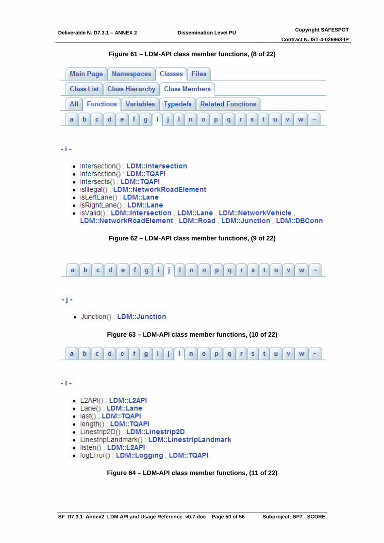
Deliverable N. D7.3.1 – ANNEX 2 Dissemination Level PU Copyright SAFESPOT
Contract N. IST-4-026963-IP
SF_D7.3.1_Annex2_LDM API and Usage Reference_v0.7.doc Page 50 of 56 Subproject: SP7 - SCORE
Figure 61 – LDM-API class member functions, (8 of 22)
Figure 62 – LDM-API class member functions, (9 of 22)
Figure 63 – LDM-API class member functions, (10 of 22)
Figure 64 – LDM-API class member functions, (11 of 22)

Deliverable N. D7.3.1 – ANNEX 2 Dissemination Level PU Copyright SAFESPOT
Contract N. IST-4-026963-IP
SF_D7.3.1_Annex2_LDM API and Usage Reference_v0.7.doc Page 51 of 56 Subproject: SP7 - SCORE
Figure 65 – LDM-API class member functions, (12 of 22)
Figure 66 – LDM-API class member functions, (13 of 22)
Figure 67 – LDM-API class member functions, (14 of 22)

Deliverable N. D7.3.1 – ANNEX 2 Dissemination Level PU Copyright SAFESPOT
Contract N. IST-4-026963-IP
SF_D7.3.1_Annex2_LDM API and Usage Reference_v0.7.doc Page 52 of 56 Subproject: SP7 - SCORE
Figure 68 – LDM-API class member functions, (15 of 22)
Figure 69 – LDM-API class member functions, (16 of 22)
Figure 70 – LDM-API class member functions, (17 of 22)
Deliverable N. D7.3.1 – ANNEX 2 Dissemination Level PU Copyright SAFESPOT
Contract N. IST-4-026963-IP
SF_D7.3.1_Annex2_LDM API and Usage Reference_v0.7.doc Page 53 of 56 Subproject: SP7 - SCORE
Figure 71 – LDM-API class member functions, (18 of 22)
Figure 72 – LDM-API class member functions, (19 of 22)
Figure 73 – LDM-API class member functions, (20 of 22)
Figure 74 – LDM-API class member functions, (21 of 22)

Deliverable N. D7.3.1 – ANNEX 2 Dissemination Level PU Copyright SAFESPOT
Contract N. IST-4-026963-IP
SF_D7.3.1_Annex2_LDM API and Usage Reference_v0.7.doc Page 54 of 56 Subproject: SP7 - SCORE
Figure 75 – LDM-API class member functions, (22 of 22)

Deliverable N. D7.3.1 – ANNEX 2 Dissemination Level PU Copyright SAFESPOT
Contract N. IST-4-026963-IP
SF_D7.3.1_Annex2_LDM API and Usage Reference_v0.7.doc Page 55 of 56 Subproject: SP7 - SCORE
5. Status of known Intellectual Property Rights (IPR) The project partners undertook an effort to check for relevant IPR concerning the technology described in this Deliverable. The content of the present document, including its two addendum (SAFESPOT LDM World Object Model and SAFESPOT LDM API) is released in public form in order to provide an official and public description of the concept and the content of the SAFESPOT LDM; to enable and to promote the usage of the LDM externally to the SAFESPOT IP; to start the standardization activities (towards the IEEE, ETSI or other possible standardization bodies); to ensure a proper level of public information is available outside of the SAFESPOT domain, in order for the original contributors (to the definition, specification and implementation of the SAFESPOT LDM) are properly acknowledged for their work on the subject. After the specific request to all SAFESPOT participants, no claims have been raised concerning IPR declared by the partners on the whole content of the present document or in its parts. Similarly, at the time of writing the release 0.6 of this Annex2 of the deliverable D7.3.1 – Global System Reference Architecture Specifications, no specific information is known to exist including patents and patent applications on the arguments dealt with or related to the SAFESPOT LDM API and Usage.

Deliverable N. D7.3.1 – ANNEX 2 Dissemination Level PU Copyright SAFESPOT
Contract N. IST-4-026963-IP
SF_D7.3.1_Annex2_LDM API and Usage Reference_v0.7.doc Page 56 of 56 Subproject: SP7 - SCORE
6. Conclusions The present document fulfills the need to describe in a public form the SAFESPOT LDM (Structure of the database, Object Model, API) from the perspective of the final users. These users need a proper level of information related to the structure and the object model of the LDM, together with the Application Programming Interface, which is practically needed to “make the proper usage” of it. With the release of the present document, the SAFESPOT consortium would like to enable and to promote the usage of the LDM externally to the SAFESPOT IP and to make feasible the standardization activities towards the IEEE, ETSI or other possible standardization bodies).
7. References [1] Wevers, K, and Becker, W, "Map attributes for heavy vehicle
applications", Proceedings 14th World Congress on Intelligent Transport Systems, October 2007, Beijing.
[2] International Organization of Standardization (ISO), International Standard ISO19125-1 and 19125-2 Geographic Information - Simple Feature Access, 2004
Addendum
• The world object model, described in chapter 3.3, is based on a MS Excel document, which is included as an additional document to the present annex (LDM data model_v10.0.12.xls), for the ease of consultation.
• The documentation of the LDM-API, described in chapter 4.3, is composed by a set of html files, generated by means of the documentation tool doxygen 1.5.6. Also these reference documents are included to the present annex as a zipped archive (PG-LDM-API-Documentation_1_7_10.zip).