space propulsion research facility (b-2): an innovative ... by nasa in the nasa sti report ... 26th...
TRANSCRIPT

Gerald M. Hill and Harold F. WeaverGlenn Research Center, Plum Brook Station, Sandusky, Ohio
Maureen T. KudlacGlenn Research Center, Cleveland, Ohio
Christian T. MaloneyGilcrest Electric & Supply Company, Sandusky, Ohio
Richard K. EvansGlenn Research Center, Plum Brook Station, Sandusky, Ohio
Space Propulsion Research Facility (B-2):An Innovative, Multi-Purpose Test Facility
NASA/TM—2011-217007
September 2011
https://ntrs.nasa.gov/search.jsp?R=20110016529 2018-06-10T02:28:27+00:00Z

NASA STI Program . . . in Profile
Since its founding, NASA has been dedicated to the advancement of aeronautics and space science. The NASA Scientific and Technical Information (STI) program plays a key part in helping NASA maintain this important role.
The NASA STI Program operates under the auspices of the Agency Chief Information Officer. It collects, organizes, provides for archiving, and disseminates NASA’s STI. The NASA STI program provides access to the NASA Aeronautics and Space Database and its public interface, the NASA Technical Reports Server, thus providing one of the largest collections of aeronautical and space science STI in the world. Results are published in both non-NASA channels and by NASA in the NASA STI Report Series, which includes the following report types: • TECHNICAL PUBLICATION. Reports of
completed research or a major significant phase of research that present the results of NASA programs and include extensive data or theoretical analysis. Includes compilations of significant scientific and technical data and information deemed to be of continuing reference value. NASA counterpart of peer-reviewed formal professional papers but has less stringent limitations on manuscript length and extent of graphic presentations.
• TECHNICAL MEMORANDUM. Scientific
and technical findings that are preliminary or of specialized interest, e.g., quick release reports, working papers, and bibliographies that contain minimal annotation. Does not contain extensive analysis.
• CONTRACTOR REPORT. Scientific and
technical findings by NASA-sponsored contractors and grantees.
• CONFERENCE PUBLICATION. Collected papers from scientific and technical conferences, symposia, seminars, or other meetings sponsored or cosponsored by NASA.
• SPECIAL PUBLICATION. Scientific,
technical, or historical information from NASA programs, projects, and missions, often concerned with subjects having substantial public interest.
• TECHNICAL TRANSLATION. English-
language translations of foreign scientific and technical material pertinent to NASA’s mission.
Specialized services also include creating custom thesauri, building customized databases, organizing and publishing research results.
For more information about the NASA STI program, see the following:
• Access the NASA STI program home page at http://www.sti.nasa.gov
• E-mail your question via the Internet to help@
sti.nasa.gov • Fax your question to the NASA STI Help Desk
at 443–757–5803 • Telephone the NASA STI Help Desk at 443–757–5802 • Write to:
NASA Center for AeroSpace Information (CASI) 7115 Standard Drive Hanover, MD 21076–1320

Gerald M. Hill and Harold F. WeaverGlenn Research Center, Plum Brook Station, Sandusky, Ohio
Maureen T. KudlacGlenn Research Center, Cleveland, Ohio
Christian T. MaloneyGilcrest Electric & Supply Company, Sandusky, Ohio
Richard K. EvansGlenn Research Center, Plum Brook Station, Sandusky, Ohio
Space Propulsion Research Facility (B-2):An Innovative, Multi-Purpose Test Facility
NASA/TM—2011-217007
September 2011
National Aeronautics andSpace Administration
Glenn Research Center Cleveland, Ohio 44135
Prepared for the26th Aerospace Testing Seminarcosponsored by the Aerospace Corporation, the Institute of Environmental Sciences and Technology and the U.S. Air Force Space and Missile Systems CenterManhattan Beach, California, March 29–31, 2011

Available from
NASA Center for Aerospace Information7115 Standard DriveHanover, MD 21076–1320
National Technical Information Service5301 Shawnee Road
Alexandria, VA 22312
Available electronically at http://www.sti.nasa.gov
Trade names and trademarks are used in this report for identification only. Their usage does not constitute an official endorsement, either expressed or implied, by the National Aeronautics and
Space Administration.
Level of Review: This material has been technically reviewed by technical management.

NASA/TM—2011-217007 1
Space Propulsion Research Facility (B-2): An Innovative, Multi-Purpose Test Facility
Gerald M. Hill and Harold F. Weaver
National Aeronautics and Space Administration Glenn Research Center
Plum Brook Station Sandusky, Ohio 44870
Maureen T. Kudlac
National Aeronautics and Space Administration Glenn Research Center Cleveland, Ohio 44135
Christian T. Maloney
Gilcrest Electric & Supply Company Sandusky, Ohio 44870
Richard K. Evans
National Aeronautics and Space Administration Glenn Research Center
Plum Brook Station Sandusky, Ohio 44870
Abstract The Space Propulsion Research Facility, commonly referred to as B-2, is designed to hot fire rocket
engines or upper stage launch vehicles with up to 890,000 N force (200,000 lb force), after environmental conditioning of the test article in simulated thermal vacuum space environment. As NASA’s third largest thermal vacuum facility, and the largest designed to store and transfer large quantities of propellant, it is uniquely suited to support developmental testing associated with large lightweight structures and Cryogenic Fluid Management (CFM) systems, as well as non-traditional propulsion test programs such as Electric and In-Space propulsion. B-2 has undergone refurbishment of key subsystems to support the NASA’s future test needs, including data acquisition and controls, vacuum, and propellant systems. This paper details the modernization efforts at B-2 to support the Nation’s thermal vacuum/propellant test capabilities, the unique design considerations implemented for efficient operations and maintenance, and ultimately to reduce test costs.
Background The Spacecraft Propulsion Research Facility, known as the B-2 test stand, is located at Plum Brook
Station, in Sandusky, Ohio. Plum Brook Station is the 2590-hectare (6400 acre) field station of the NASA Glenn Research Center. The Station was designed to handle large quantities of gaseous or cryogenic propellants and purge/pressurants necessary for rocket engine testing and nuclear electric-propulsion; therefore, the test facilities are located within large clear exclusion zones with remote command and control centers.
B-2, depicted in Figure 1, was designed to hot-fire test large upper-stage rocket engines utilizing cryogenic fuels and oxidizers, primarily liquid hydrogen (LH2) and liquid oxygen (LO2). The facility was sized to accommodate a full-scale upper-stage (with onboard cryogenic fuels and oxidizers) or just the engine subsystem. The high altitude conditions approximately 30,000 m (100,000 ft) are maintained prior

NASA/TM—2011-217007 2
Figure 1.—B-2 cutaway.
to, during, and after engine firing (Ref. 1). The vehicle or system being tested can be subjected to simulated orbital conditions for indefinite periods prior to, or after engine firing. A liquid nitrogen (LN2) cold wall, which completely covers the wall of the chamber and lid, can provide temperatures to –196 °C (320 °F) and a vacuum level of 7×10⁻⁶ Pa (5×10⁻⁸ Torr). A radiant heating system can produce 1400 W/m2 (130 W/ft2). In this manner, a test can be designed to demonstrate the full mission profile that an upper-stage propulsion system would experience. B-2 is the only facility in the world capable of engine restart after on-orbit thermal vacuum environments simulation.
In 2006, with anticipation to meeting NASA’s future needs for thermal vacuum upper-stage engine testing as well as those of commercial and international customers, B-2 underwent a systematic, phased refurbishment program to revitalize all major facility subsystems and ancillary infrastructure equipment. NASA’s Space Operations Mission Directorate (SOMD) and Exploration Systems Mission Directorate (ESMD) have funded this activity, under the guidance of the Rocket Propulsion Test Management Board (RPTMB), a NASA Level II office responsible for maintaining the agency’s chemical propulsion test capability. To date this refurbishment includes the chamber and all vacuum systems, propellant and pressurant systems, control and data acquisition systems, and numerous facility support systems.

NASA/TM—2011-217007 3
Centaur Upper Stage TRACER (Transition Radiation Array for Cosmic Energetic Radiation)
Figure 2.—B-2: A multifunctional test facility.
While the facility was designed to hot-fire upper-stage LH2/LO2 engines such as the RL-10, it is also NASA’s third largest thermal vacuum test facility, and by far the largest with the capability to process large quantities of propellants by design. Historically, over 50 percent of the tests performed at B-2 have been non-propulsion thermal-vacuum tests. As the planning for the refurbishment of altitude systems continue, B-2 is available for full-scale spacecraft thermal vacuum testing, with propellants, in support of NASA and industry’s Design, Development, Test and Evaluation (DDT&E) efforts. The B-2 revitalization project aims to reduce the cost of maintenance and test operations through unique design and operational concepts, providing highly reliable and available subsystems leading to quality data with known uncertainties and minimized test costs for customers.
Nontraditional test opportunities being considered include Cryogenic Fluid Management (CFM), Electric Propulsion, space mechanisms and structures, and main propulsion systems components testing. Test programs prior to the facility refurbishment project have included the Centaur Upper Stage, the Mars Exploration Rover (MER) Cold inflation Test Program, the Transition Radiation Array for Cosmic Energetic Radiation (TRACER) Altitude Test, Pulse Detonation Research Engine (PDRE), Solar Array Plume Interaction Tests, as well as the Delta X Stage test. The Centaur Upper Stage and TRACER are shown in Figure 2. This paper will detail the facility capabilities, including the unique design considerations implemented for efficient operations and maintenance that ultimately reduced test costs to our customers.
Test Chamber Central to the Spacecraft Propulsion Research Facility is the test chamber, where space environment
conditions are replicated. The test chamber is a stainless steel cylinder with an inside diameter of 11.6 m (38 ft) and capped with a hemispherical dome of matching diameter. The bottom of the chamber is

NASA/TM—2011-217007 4
essentially a flat plane with the exception of the inner 6.7 m (22 ft) diameter, which is hemispherically domed inward to support the diffuser duct. Attached to the bottom of the chamber is a diffuser duct 3.4 m (11 ft) in diameter and approximately 11.3 m (37 ft) long, for decelerating a rocket engine exhaust plume. The duct is at the same vacuum level as the remainder of the chamber. The spray chamber is located at the exit of the exhaust diffuser and is isolated from the test chamber and exhaust diffuser during high vacuum operation. In the spray chamber, rocket exhaust is quenched and non-condensable products of combustion are removed with steam ejectors (Ref. 2).
The nominal test article envelope is 6.7 m (22 ft) diameter by 15.8 m (52 ft) maximum vertical clearance. Typical test article installation into the test chamber is via a hinged hatch at the top of the hemispherical dome using a 20-ton overhead crane. The hatch is 8.2 m (26 ft 9 in.) in diameter. Personnel and small equipment access is available via 1.8 m- (6 ft-) diameter circular doors located at the bottom of the chamber and at 12.5 m (41 ft) above the bottom of the chamber. Numerous high-vacuum penetrations exist at multiple elevations for routing of fluids and electrical power, or signals internal to the chamber without compromising the vacuum environment. A cross-section elevation view of the test chamber is shown in Figure 3.
The test chamber can be evacuated to absolute pressures down to 1×10⁻⁴ Pa (1×10⁻⁶ Torr) without gas load and without the heat sink operating. Intermediate absolute pressures can also be maintained. Operation of the heat sink reduces absolute pressure levels to approximately 7×10⁻⁶ Pa (5×10⁻⁸ Torr).
Ultimate vacuum conditions are achieved via ten 89 cm- (35 in.-) diameter oil diffusion pumps with integral (water) cold caps. These elbows are cooled to approximately 7.2 °C (4.5 °F) by a chilled glycol system to further condense diffusion pump oil and minimize backstreaming rates.
Thermal simulation of near earth space conditions within the test chamber is accomplished via a LN2 heat sink (also called a cold wall) and an infrared lamp array.
Figure 3.—Test Chamber cross-section view.

NASA/TM—2011-217007 5
The LN2 heat sink lines the entire interior of the test chamber, producing a final chamber interior clear diameter of 10.4 m (34 ft) and height envelope of 17 m (56 ft) on chamber centerline. Coverage includes the access hatch, which has a separate LN2 heat sink attached. The only portion of the chamber not having integrated heat sink coverage is a 6.7 m (22-ft) diameter circle on the floor level of the chamber. A separate, test-specific removable LN2 heat sink has been used in past tests to obtain uniform temperature distribution on the floor level, when required. Figure 4 shows a picture of the cold wall installed in the chamber
The cold wall is filled with gravity-fed LN2 from a flash tank located above the vacuum chamber into a supply manifold located at the base of the chamber. The geometry of the tube-in-strip panel arrangement results in an optically dense surface. The heat sink provides a uniform temperature environment of approximately –196 °C (–320 °F). Made of copper to optimize thermal conduction, the cold wall can be coated with flat black lacquer paint for high emissivity properties.
The infrared lamp array is designed to produce a heat flux pattern on the test article simulating solar exposure on one side of a test article. Currently, the array is configured with 12 individually controllable “zones”. Each zone consists of a vertical column of tungsten quartz infrared lamps spanning from the test chamber floor to a height of 36 ft above floor level. Each column contains of 48 750 W lamps, for a column power of 36 kW and a total array power of 432 kW. Lamp power is supplied by 12 power controllers that are rated at 50 kW each for a capacity of 600 kW.
The 12 columns are distributed over a 109° arc of the test chamber circumference. The array can be controlled to provide a sinusoidal distribution of the flux pattern on the test article or other pattern as required. The radiant heat flux at the nominal test article radial envelope of 6.7 m (22-ft) diameter is 1400 W/m2. Other mounting points exist for locating reflector columns at other circumferential locations within the chamber.
Figure 4.—Cold wall installed in Vacuum Chamber.
NASA/TM—2011-217007 6
The vacuum system and test chamber were the focus of a complete refurbishment effort starting in 2007. This effort included the rebuilding of all mechanical components within the pumping train, such as blowers and valves. In addition, the system instrumentation was modernized with new sensors, (pressures, temperatures, accelerations, revolutions per minute) including additional sensors added at strategic locations. Instrumentation was incorporated to allow safe, unattended steady-state operation of the system. The system controls were also completely replaced with current generation architecture and components. The controls now allow for the system to monitor operating parameters of the system and individual equipment, and initiate appropriate automated actions to safeguard the test chamber and/or system components in the event of out of bounds conditions. The refurbishment effort culminated with test chamber evacuation and system verification testing in September 2009. The testing proved successful, achieving pressure levels of 6.6×10⁻⁴ Pa (5×10⁻⁶ Torr) without the heat sink.
Future planned restoration work includes installation of a new residual gas analyzer to monitor the gas constituents of the chamber atmosphere, replacing the cooling water system for increased vacuum system operational reliability, and recoating the LN2 cold wall with a high emissivity coating for optimum thermal performance.
Propellants and Pressurants The facility can provide a variety of propellants and gases to support testing including LH2, LO2, LN2,
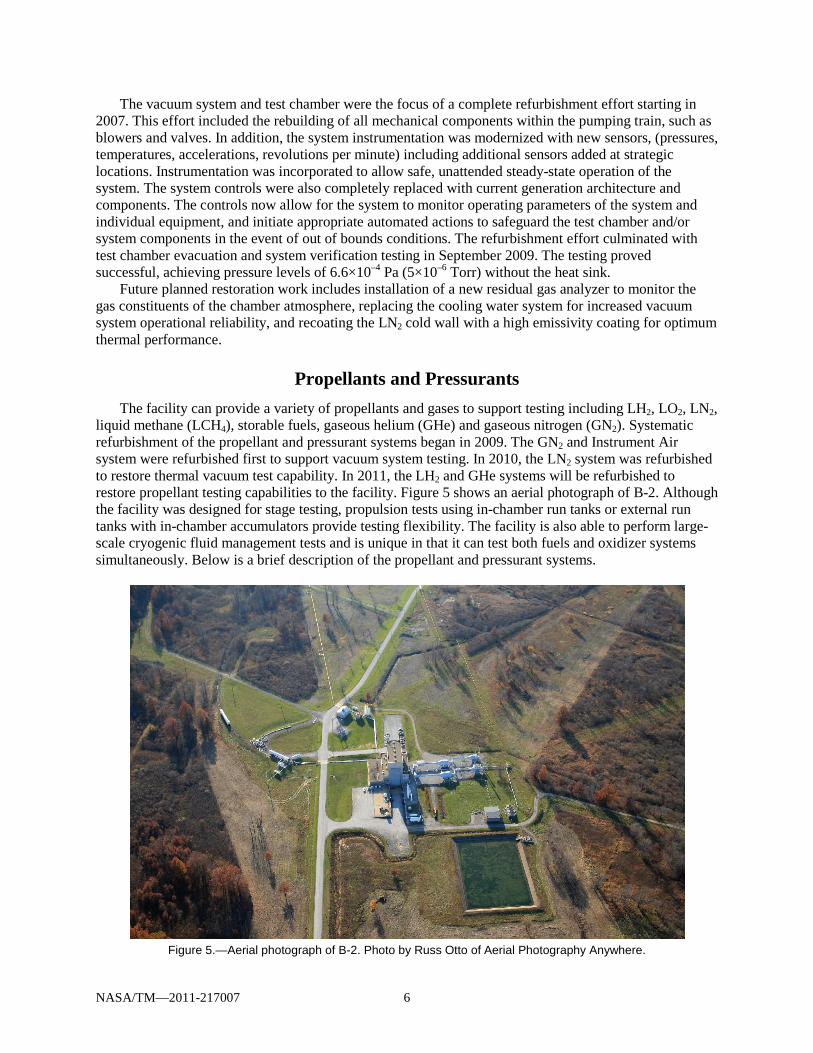
liquid methane (LCH4), storable fuels, gaseous helium (GHe) and gaseous nitrogen (GN2). Systematic refurbishment of the propellant and pressurant systems began in 2009. The GN2 and Instrument Air system were refurbished first to support vacuum system testing. In 2010, the LN2 system was refurbished to restore thermal vacuum test capability. In 2011, the LH2 and GHe systems will be refurbished to restore propellant testing capabilities to the facility. Figure 5 shows an aerial photograph of B-2. Although the facility was designed for stage testing, propulsion tests using in-chamber run tanks or external run tanks with in-chamber accumulators provide testing flexibility. The facility is also able to perform large-scale cryogenic fluid management tests and is unique in that it can test both fuels and oxidizer systems simultaneously. Below is a brief description of the propellant and pressurant systems.
Figure 5.—Aerial photograph of B-2. Photo by Russ Otto of Aerial Photography Anywhere.

NASA/TM—2011-217007 7
Liquid hydrogen is supplied to the B-2 vacuum chamber from an existing 130,218 L (34,400 gal) LH2 railcar parked on a rail siding 90 m (300 ft) south of the B-2 test building. LH2 is pressure-transferred into test articles located in the vacuum chamber through a 76.2 mm (3 in.) vacuum jacketed pipe. The system is designed to allow propellant from the test chamber to be returned to the storage dewar. Vent gases from the test article are discharged above the roofline with a maximum nominal flow rate of 0.23 kg/sec (0.5 lb/s). In the event of an off-nominal situation in the test article, LH2 can be rapidly dumped into a vessel located in the spray chamber. A low-pressure vent system is used to vent hydrogen gas to sub-atmospheric conditions using a steam ejector. The low-pressure vent system handles short duration high flow venting. In 2010, a 124,919 L (33,000 gal) LH2 storage tank was relocated from the NASA Kennedy Space Center to augment B-2’s storage capacity. The new storage tank is located in parallel with the LH2 rail car. Future plans include reconfiguring the LH2 transfer piping to support transfer to and from the new vessel. Additionally, a hydrogen altitude exhaust system for venting hydrogen gas is planned to support long duration low flow venting that would be typically seen during long duration cryogenic missions.
The LH2 transfer system has been examined and it has been determined that the LH2 piping system is capable of supporting LCH4 testing. Presently, LCH4 storage capacity would be limited to the capacity of commercial delivery trailers. Future plans involve examining existing LH2 storage vessels for their compatibility with LCH4.
Liquid oxygen is supplied to the B-2 vacuum chamber from an existing 45,425 L (12,000 gal) fixed storage dewar located approximately 45.7 m (150-ft) northeast of the test building. LO2 is pressure-transferred to test articles located in the vacuum chamber through a 102 mm (4 in.) insulated pipe. The system is designed to allow propellant from the test chamber to be returned to the storage dewar. LN2 can be fed into the system from a trailer station located near the LO2 storage dewar for checkout or test article use. Vent gases from the test article and transfer system are vented to atmosphere. In the event of an off-nominal situation in the test article, LO2 can be rapidly dumped into a vessel located in the spray chamber beneath the vacuum chamber. Future plans include refurbishment of the LO2 storage vessel, transfer system and LO2 dump tank. An oxygen altitude exhaust system for venting oxygen gas is also planned to support long duration low flow venting that would be typically seen during long duration cryogenic missions.
Liquid nitrogen is fed from a remote storage facility 457 m (1500 ft) southwest of the test building. During long duration cold soak of a test article LN2 consumption is approximately 76 Lpm (20 gpm), but when the facility infrared lamp arrays are in use LN2 consumption reaches 385 Lpm (100 gpm). LN2 is pressure-fed through a 63.5 mm (2.5 in.) diameter insulated line to the test chamber. The remote LN2 storage facility is located outside of the test exclusion zone and allows for safe convenient commercial LN2 delivery. The remote storage facility has two 105,992 L (28,000 gal) LN2 dewars. One of the two dewars is currently configured to feed the cold wall. The second LN2 dewar is planned to be reconfigured to support cold wall operations which will ease delivery logistics during long duration thermal simulation tests.
The facility is designed to test storable fuels, such as Aerozine 50, kerosene, and RP-1 rocket propellant. A 24,605 L (6500 gal) tank is located east of the LH2 storage dewar. The system is designed to pressurize transfer storable fuels from the supply area into the test chamber through a 76-mm (3 in.) stainless steel line. Vent gases from the test article and transfer system are vented to atmosphere. In the event of an off-nominal situation in the test article, the storable fuel can be rapidly dumped into a 14,385 L (3800 gal) vessel located in the spray chamber beneath the vacuum chamber. Future plans include further examination and refurbishment of the storable fuels system.
The GHe system is used for purging/inerting the LH2 and GH2 systems, and available for use as a pressurant. GHe is fed from tube trailers and a bottle farm located east of the facility. Refurbishment of the GHe system will be completed in 2011.
The GN2 is used to pressurize/purge the oxygen system, provide pressurant for the hydraulic accumulators, purge/pressurize some enclosures to meet the National Electrical Code (NEC) safety standards, and to act as a back up to the service air system for valve actuation. GN2 is fed from tube trailers and a bottle farm. The GN2 system has been refurbished.
NASA/TM—2011-217007 8
The air system is used for valve actuation, pressurization of enclosures to meet the NEC hazardous environments safety standards, and operation of shop tools. The compressor has a capacity of 12,629 L/min (446 ft3/min) and there is a 14.9 m3 (527 ft3) air accumulator in the system. The air system was refurbished in 2010.
The B-2 facility is a flexible test facility. Customer required systems such as GH2 and GO2 have been added as special test equipment for specific tests.
Control Systems Operation of the B-2 Test Facility is from a separate building, B-Control, which is located 780 m
(2,560 ft) west of the test building. The remote location is necessary due to the hazards associated with testing at B-2. All data and control interfaces at the test facility terminate in the equipment rooms at B-2, shown in Figure 6. The equipment rooms house signal conditioning and Data Acquisition System (DAS) analog-to-digital (A/D) converters in the Data Room, the control system interfaces in the Terminal Room; two other rooms house power distribution and vacuum pumping equipment. These equipment rooms are pressurized to meet Class I, Division 2, Group B requirements per the NEC.
Prior to the current modernization effort, test operations existed through hardwired push buttons, interlocks, and relays. The interfaces were made through multiple buried cables from B-Control to the test facility. Although sufficient for testing in the 1970s, underground cabling limits bandwidth and channel expansion, and had deteriorated over the years. Except for some hardwired safety systems, most communications with the test site is currently over fiber.
The controls system has been modernized using a distributed architecture whose primary intelligent modules are Programmable Logic Controllers (PLC) and Human Machine Interface (HMI) workstations, also referred to as Graphical User Interfaces (GUI), based around a Server/Client System Architecture. The system is designed to offer a robust, redundant architecture with high flexibility and expansion capabilities. One of the key components to the modernization of the B-2 Test Facility was to convert the facility’s existing hard-wired control system(s) to a distributed PLC and HMI based Control System Architecture.
The control system also consists of remote input/output (RIO) drops to minimize field wiring to
equipment. RIO drops can also be expanded to handle new requirements and processes as needed. An advantage of a PLC-based controls system is the ability to communicate between systems and processes. The B-2 Control system is designed with emphasis on controlling facility operations, auto sequencing and test abort conditions, and control of the major sub-systems. Additionally the control system is used to monitor facility ancillary systems, and keep a log of key parameters with the goal to aid in the condition-based maintenance of that hardware.
With a PLC-based control system, capabilities are expanded with the use of HMIs to replace hardwired control panels. Advantages of having an HMI go beyond the ease of adding graphics, they provide the capability to include features such as password protection to limit operations to qualified personnel, pop-ups to force a two-step process to prevent inadvertent operation, animation of objects to show status, and the ability to have standardization in the design of the operator screen. Figure 6 shows an HMI screen for the B-2 vacuum system.
Human factors were considered in the design of operator screens. This includes standardized status, alarm, and shortcut buttons, color-coded process systems piping, pop-up control screen standardization, and two-step decision-making operation wherever possible.

NASA/TM—2011-217007 9
Figure 6.—Typical HMI Control Screen for the B-2 Vacuum System.
PLCs have been used for decades in industry due to their robustness. To further extend the control system’s availability and reliability, the B-2 Control System is designed with redundancy at several levels, including a hot standby PLC, HMI data servers, networking and cabling, and redundant HMI workstations. It is a recent reality that today’s PLCs have dual co-processors to minimize the scan time, thereby enabling a hot standby configuration as a viable risk reduction choice for the system architecture.
One of the advantages of the HMI Server/Client Architecture is the ability to expand. The B-2 system consists of eight workstations, with expansion if required. Another benefit is the ability to add functionality and additional data points without additional cost. This capability also makes the control system seamless in adding functionality to handle multiple test stands or facilities if required.
The B-2 Control system is capable of generating alarms based on set points and derived system requirements. Workstations can be configured to display specific alarms for any given system(s) or display all alarms. The system produces event logs with a time/date stamp showing a history of events at any workstation. The event log records the name of the operator and records operator activity. The event log is beneficial in troubleshooting when anomalies exist, processes are out of tolerance, or questions arise concerning operator error. The control system is capable of recording data through its historian data collection server. The system can handle up to 2,500 tags and be expanded up to 250,000 tags with additional investment.
A unique feature of the B-2 Control System is the event notification system. This system allows configuration of any alarm condition to dial out a phone message alerting a first responder, which aids in

NASA/TM—2011-217007 10
unattended operations. It will also enable audible instructions to personnel, per protection zone, in the event of a hydrogen fire or leak detection event.
One of the key design requirements was to ensure Information Technology (IT) security of the control system and DAS. This includes restricted access to B-Control, including the control room and the data lab, and the data and termination rooms at B-2. The control room is reserved for test operations, while the data lab houses computer hardware such as operator stations, servers, DAS, the video matrix switch, storage, and (IRIG) time stamp generator. Each workstation is password-protected to restrict the inadvertent shutdown of the HMI Software. The Data Lab provides temperature and humidity controls for the computer equipment. The Data Lab is also used for DAS storage, control and display functions, data reduction and transmission, in addition to video, network and communication systems.
Operator station keyboard, video monitor, and mouse are extended from the data lab to the operator consoles in the control room. Video monitors are available on the monitor wall, as well as local to the test subsystem operators, test conductor and test customers. A centralized video controller can control which view is associated with a monitor, the pan tilt and zoom functions, and multiple views per monitor features. A 3-terabyte Digital Video Recorder hard drive is available to record the time stamped video channels.
Additional media available at the operator consoles include single and multimode fiber, video, control and data cabling. This allows the control room to be configured as required for test operations, test engineering, QA, and customer needs. Unique test requirements such as high speed video, mission simulators, and test article controls can be accommodated efficiently, minimizing test costs associated with augmenting the control room on a case by case basis.
Data Acquisition System Prior to refurbishment of B-2’s Control and DAS system, all signals were transmitted from the
facility to the control room through in-ground cabling over one-half mile long. This limited the bandwidth, was not expandable, and had become obsolete. Except for some hardwire safety control circuits most of the signals now utilize fiber between B-2 and B Control. This enables the distributed architecture now used for the DAS.
The B-2 DAS includes the signal conditioning electronics, data recording, storage, display, and archive systems. Like the control system, the B-2 facility DAS employs a distributed architecture which is designed to meet the unique challenges of a space environmental upper-stage engine testing facility. In addition to addressing the specific requirements of performing large-scale data acquisition for test articles in a thermal-vacuum chamber, the B-2 DAS architecture also meets the hazardous environments NEC code safety requirements for tests which involve the use of propellants (Class 1 Group B Division 2).
As discussed previously, the facility has a dedicated Data Room at the test site. This location minimizes the transducer cabling impedance, while protecting sensitive equipment from the environments produced by the test facilities. The Data Room allows the front-end electronics of the DAS to operate safely by providing a constant positive air pressure in the room. This allows the signal conditioning and digitizing electronics to function close to the test chamber when propellants are present in the chamber.
Furthermore, the distributed architecture of the DAS is used to mitigate the risk of the potential loss of data in a catastrophic scenario. Once the analog measurements are digitized in the Data Room the resulting data is streamed immediately via fiber optics to data recording units that are located at the B-Control building outside the B-2 facility exclusion zone, approximately one-half mile away from the test facility. This is graphically displayed in Figure 7. Joined together by a 4 GBit fiber-channel switch fabric, the digitizers and the recording units form a fourth generation storage area network for which the distance between the digitizers at the B-2 test site and the recording units at B-Control does not introduce any appreciable time delay. The data is recorded remotely with the same latency it would have if the recoding units were located in Data Room with the digitizers.

NASA/TM—2011-217007 11
Figure 7.—Signal flow from Test Chamber to storage/display.
The B-2 DAS and is based entirely on Commercial off the Shelf (COTS) hardware, and open
hardware/software standards. The acquisition stations which house the A/D converters, digital signal processor (DSP) board, Fibre Channel (FC) interfaces, and G4 Power PC embedded processors are connected to RAID storage arrays by a storage area network (SAN) over FC. The architecture is designed to guarantee deterministic data acquisition at designed bandwidth per channel. There are currently 576 channels of A/D’s arranged in 32-channel subsystems, including low speed, high speed and discrete channels. Data is synchronized through a clock generator which is phase-locked to an externally supplied IRIG–B signal for accurate time stamping.
The data lab in the B-Control building houses the control, monitor, and archive workstations. The control workstation runs the application to configure the hardware, define the test parameters, and control access to the test data. There are three monitor workstations that run the visualization software for near real-time data display, as well as the limit-check monitoring software. The archive server runs software to back up acquired data to mass storage and the Linear Tape-Open (LTO) magnetic tape library. The software has the capability to locate and serve archived data to other workstation clients (test customers) for analysis, reduction or transmission. An on-line post processing workstation is available to define and automatically execute analyses on any number of channels once acquisition is complete. Data displays and control interfaces are extended to the control room shown in Figure 8.
The B-2 DAS includes signal conditioners to condition response transducers used in a wide variety of measurements including both high-speed (SR > 5 kHz) and low-speed (SR <4 kHz) sample rates used for a diverse range of measurements. Hardware self-tests and calibrations are traceable to National Institute of Standards and Technology (NIST). Programming of the conditioning system via Ethernet is controlled through the DAS control computer using the Test Definition Editor. For configuration management purposes, all parameters associated with the measurement are contained in this test definition file.
All of the signal conditioners have a 4-pole programmable low-pass Flat/Pulse filters (300 Hz to 30 kHz, as well as Bypass mode), for either time or frequency domain. The amplified output voltage of the signal conditioners can be buffered and made available as needed to other systems, such as the controls system and/or the red-line abort system as required.

NASA/TM—2011-217007 12
Figure 8.—B-2 Control Room.
While the functional role of the signal conditioning system in the B-2 DAS is to accurately process
the analog portion of the signal chain, it is the commercial off the shelf (COTS) digitizing and data processing system and transducer interface cabling which completes the functional description of the B-2 DAS system. There are many DAS requirements that relate strictly to the capabilities of a digital acquisition system (DAS), however, good system design places limitations on the location of hardware, cable lengths, transmission media, and data transport. Keeping the digitizers close to the signal conditioner outputs minimizes the cabling between the two systems, and reduces the risk of any un-wanted transmission line effects between the signal conditioning system’s outputs and the digitizer system’s inputs. While the benefit of this design choice is clearly recognized at the boundary between the two systems, the choice puts additional requirements on the digitizing system to be selected; specifically, the ability to keep all of the individual digitizer sample clocks synchronized and the ability to transport the resulting data effectively. The B-2 DAS is a complete COTS turn-key data acquisition system solution with numerous state-of-the-art features, including the ability to provide complete control of the signal conditioning system, in effect treating the signal conditioning system as a native part of the DAS. Multiple digitizer bricks can be operated independently or in concert to form more complex systems with larger channel counts. The digitizer bricks are joined together on a 4 Gbps Fiber-Channel Switched Fabric along with remote RAID units and Control PCs to form the Storage-Area Network (SAN). This architecture provides an unprecedented level of modularity and scalability that maximizes the versatility of the over-all system without compromising the system’s high-speed capabilities (Ref. 3).

NASA/TM—2011-217007 13
Summary The Space Propulsion Research Facility (B-2) has a rich history of upper stage propulsion testing in
relevant space environments, as well as non-propulsion thermal vacuum testing. B-2 is the only facility in the national inventory that combines long-duration, high-vacuum space environment simulation, hot-fire test capability, and engine restart capability. As the Space Shuttle Transportation System (SSTS) nears retirement, and the agency redirects its efforts to develop transportation systems to fill the void and meet new mission requirements, B-2 will continue to support ground testing of these systems. Revitalization of the facility is underway, with near term capability to support thermal vacuum testing with large quantities of propellants, such as those required for DDT&E of cryogenic fluid management technologies required for propellant depots or large vehicle propellant storage systems. At each phase of refurbishment the goal is to design systems that leverage current technologies to create a highly available, safe and cost effective test capability with a vision towards maintainability, reliability, and testing flexibility.
References 1. Meyer, Michael L., Dickens, Kevin. W., Skaff, Tony F., Cmar, Mathew J., Haberbusch, Mark S.,
“Performance of the Spacecraft Propulsion Research Facility During Altitude Firing Tests of the Delta III Upper Stage, NASA TM–208477, AIAA–98–4010, 1998.
2. Klein, W.E., “Spacecraft Propulsion Research Facility (B-2) at the Lewis Research Center’s Plum Brook Station,” SAE Paper 931437, Aerospace Atlantic Conference and Exhibition, April 20–23, 1993.
3. Hill, Gerald, and Evans, Richard, “Advanced Distributed Measurements and Data Processing at the Vibro-Acoustic Test Facility, GRC Space Power Facility, Sandusky, OH—An Architecture and an Example,” Proc. of the 25th Aerospace Testing Seminar, USAF/The Aerospace Corporation, Oct. 2009.

REPORT DOCUMENTATION PAGE Form Approved OMB No. 0704-0188
The public reporting burden for this collection of information is estimated to average 1 hour per response, including the time for reviewing instructions, searching existing data sources, gathering and maintaining the data needed, and completing and reviewing the collection of information. Send comments regarding this burden estimate or any other aspect of this collection of information, including suggestions for reducing this burden, to Department of Defense, Washington Headquarters Services, Directorate for Information Operations and Reports (0704-0188), 1215 Jefferson Davis Highway, Suite 1204, Arlington, VA 22202-4302. Respondents should be aware that notwithstanding any other provision of law, no person shall be subject to any penalty for failing to comply with a collection of information if it does not display a currently valid OMB control number. PLEASE DO NOT RETURN YOUR FORM TO THE ABOVE ADDRESS.
1. REPORT DATE (DD-MM-YYYY) 01-09-2011
2. REPORT TYPE Technical Memorandum
3. DATES COVERED (From - To)
4. TITLE AND SUBTITLE Space Propulsion Research Facility (B-2): An Innovative, Multi-Purpose Test Facility
5a. CONTRACT NUMBER
5b. GRANT NUMBER
5c. PROGRAM ELEMENT NUMBER
6. AUTHOR(S) Hill, Gerald, M.; Weaver, Harold, F.; Kudlac, Maureen, T.; Maloney, Christian, T.; Evans, Richard, K.
5d. PROJECT NUMBER
5e. TASK NUMBER
5f. WORK UNIT NUMBER WBS 750271.01.03
7. PERFORMING ORGANIZATION NAME(S) AND ADDRESS(ES) National Aeronautics and Space Administration John H. Glenn Research Center at Lewis Field Cleveland, Ohio 44135-3191
8. PERFORMING ORGANIZATION REPORT NUMBER E-17670
9. SPONSORING/MONITORING AGENCY NAME(S) AND ADDRESS(ES) National Aeronautics and Space Administration Washington, DC 20546-0001
10. SPONSORING/MONITOR'S ACRONYM(S) NASA
11. SPONSORING/MONITORING REPORT NUMBER NASA/TM-2011-217007
12. DISTRIBUTION/AVAILABILITY STATEMENT Unclassified-Unlimited Subject Category: 14 Available electronically at http://www.sti.nasa.gov This publication is available from the NASA Center for AeroSpace Information, 443-757-5802
13. SUPPLEMENTARY NOTES
14. ABSTRACT The Space Propulsion Research Facility, commonly referred to as B-2, is designed to hot fire rocket engines or upper stage launch vehicles with up to 890,000 N force (200,000 lb force), after environmental conditioning of the test article in simulated thermal vacuum space environment. As NASA’s third largest thermal vacuum facility, and the largest designed to store and transfer large quantities of propellant, it is uniquely suited to support developmental testing associated with large lightweight structures and Cryogenic Fluid Management (CFM) systems, as well as non-traditional propulsion test programs such as Electric and In-Space propulsion. B-2 has undergone refurbishment of key subsystems to support the NASA’s future test needs, including data acquisition and controls, vacuum, and propellant systems. This paper details the modernization efforts at B-2 to support the Nation’s thermal vacuum/propellant test capabilities, the unique design considerations implemented for efficient operations and maintenance, and ultimately to reduce test costs. 15. SUBJECT TERMS Propulsion; Propellants; Research facility; Environmental tests
16. SECURITY CLASSIFICATION OF: 17. LIMITATION OF ABSTRACT UU
18. NUMBER OF PAGES
20
19a. NAME OF RESPONSIBLE PERSON STI Help Desk (email:[email protected])
a. REPORT U
b. ABSTRACT U
c. THIS PAGE U
19b. TELEPHONE NUMBER (include area code) 443-757-5802
Standard Form 298 (Rev. 8-98)Prescribed by ANSI Std. Z39-18

