spacecraft autonomy using onboard processing for
TRANSCRIPT

SPACECRAFT AUTONOMY USING ONBOARD PROCESSING FOR A SAR CONSTELLATION MISSION
Rob Sherwood, Steve Chien, Rebecca Castano, Gregg Rabideau Jet Propulsion Laboratory, California Institute of Technology
4800 Oak Grove Dr., Pasadena, CA 91 109 [email protected]
http://ase.jpl.nasa.gov
Abstract. The Autonomous Sciencecraft Experiment (ASE) will fly onboard the Air Force TechSat 21 constellation of three spacecraft scheduled for launch in 2006. ASE uses onboard continuous planning, ro- bust task and goal-based execution, model-based mode identification and reconfiguration, and onboard ma- chine learning and pattern recognition to radically increase science return by enabling intelligent downlink selection and autonomous retargeting. In this paper we discuss how these AI technologies are synergisti- cally integrated in a hybrid multi-layer control architecture to enable a virtual spacecruft science agent. Demonstration of these capabilities in a flight environment will open up tremendous new opportunities in planetary science, space physics, and earth science that would be unreachable without this technology.
1 Introduction
There is an increasing desire in many organizations, including NASA and the DoD, to use onboard decision- making to accomplish complex mission objectives. The Air Force Research Laboratory (AFRL) has initiated the TechSat 21 program to serve as a demonstration mission for a new paradigm for space missions. This para- digm seeks to reduce costs and increase system robustness and maintainability by using onboard autonomy to enable faster response times and improve operations efficiency.
TechSat 21 is scheduled for launch in January 2006 and will fly three satellites in a near circular orbit at an al- titude of approximately 550 Km. The primary mission is one-year in length with the possibility for an extended mission of one or more additional years. During the mission lifetime the cluster of satellites will fly in various configurations with relative separation distances of approximately 100 meters to 5 Km. One of the objectives of TechSat 21 is to assess the utility of the space-based, sparse-array aperture formed by the satellite cluster. For TechSat 21, the sparse array will be used to synthesize a large radar antenna. Three modes of radar sensing are planned: synthetic aperture radar (SAR) imaging, moving target indication (MTI), and geo-location.
The principal processor onboard each of the three TechSat 21 spacecraft is a BAE Radiation hardened 175 MIF’S, 133MHz PowerPC 750 running the OSE 4.3 operating system from Enea Systems. OSE was chosen because it is inherently message passing based and particularly suitable for distributed applications. Each satel- lite will have 256 Kbytes of EEPROM for boot loads and 128 Mbytes of SDRAM. Communications will be through a Compact PCI bus.
*
The ASE onboard flight software includes several autonomy software components:
Onboard science algorithms that will analyze the image data to detect trigger conditions such as sci- ence events, “interesting” features, and changes relative to previous observations Robust execution management software using the Spacecraft Command Language (SCL) [7] pack- age to enable event-driven processing and low-level autonomy The Continuous Activity Planning, Scheduling, and Replanning (CASPER) [4] planner that will re- plan activities, including downlink, based on science observations in the previous orbit cycles Model-based mode identification and execution software that uses component-based hardware mod- els to analyze anomalous situations and to generate novel command sequences and repairs. Observation Planning (OP) software will enable the satellites to predict overflights of targets to fa- cilitate onboard retasking.

Fig. 1. ASE Mission Scenario
The onboard science algorithms will analyze the images to extract static features and detect changes relative to previous observations. Prototype software has already been demonstrated on X-band radar data (from shuttle missions) to automatically identify regions of interest including: regions of change (such as flooding, ice melt, and lava flows), and feature recognition (such as crater and volcano recognition). Such onboard science will enable retargeting and search, e.g., shifting the radar aim-point on the next orbit cycle to identify and capture the full extent of a flood. On future interplanetary space missions, onboard science analysis will enable capture of short-lived science phenomena at the finest time-scales without overwhelming onboard caching or downlink capacities. Examples include: eruption of volcanoes on Io, formation of jets on comets, and phase transitions in ring systems. Generation of derived science products (e.g., boundary descriptions, catalogs) and change-based triggering will also reduce data volumes to a manageable level for extended duration missions that study long- term phenomena such as atmospheric changes at Jupiter and flexing and cracking of the ice crust on Europa.
The onboard planner (CASPER) will generate mission operations plans from goals provided by the onboard science analysis module. The model-based planning algorithms will enable rapid response to a wide range of operations scenarios based on a deep model of spacecraft constraints, including faster recovery from spacecraft anomalies. The onboard planner will accept as inputs the science and engineering goals and ensure high-level goal-oriented behavior for the constellation.
The robust execution system (SCL) accepts the CASPER-derived plan as an input and expands the plan into low-level commands. SCL monitors the execution of the plan and has the flexibility and knowledge to perform event-driven commanding to enable local improvements in execution as well as local responses to anomalies.
One of the ASE demonstration scenarios involves monitoring of flooding regions in Arizona. (See Fig. 1.) Radar data have been used in ground-based analysis to study this phenomenon. The ASE concept would be ap- plied as follows:
1.
2.
3. 4. 5.
6.
Initially, ASE has a list of science targets to monitor that have been sent as high-level goals from the ground. As part of normal operations, CASPER generates a plan to monitor the targets on this list by periodi- cally imaging them with the radar. During execution of this plan, a spacecraft images a river area with its radar. Onboard, a reflectivity image is formed. The Onboard Science Sofnyare compares the new image withprevious image and detects that the water region has changed due to flooding. Based on this change the science software generates a goal to acquire a new high-resolution image of an area of flooding. The addition of this goal to the current goal set triggers CASPER to modify the current operations plan to include numerous new activities in order to enable the new science observation. During this process CASPER interacts with the Observation Planner to compute when the spacecraft will fly over the target and determine the required slews to acquire the target.
dJJ
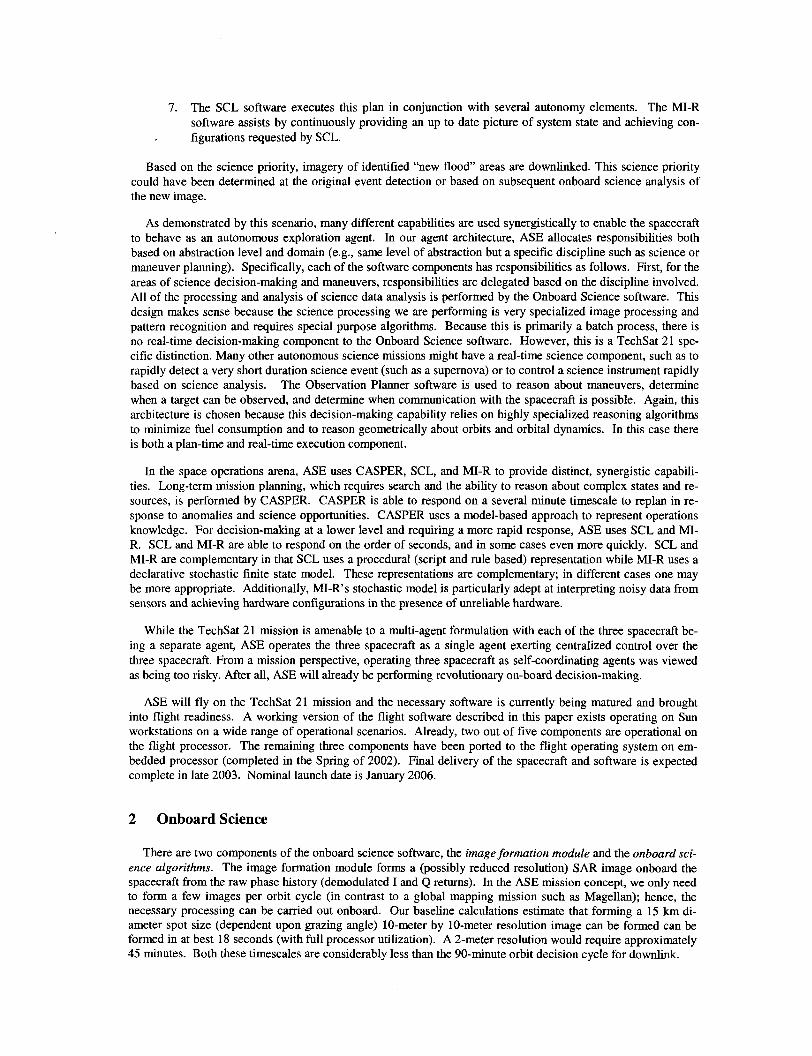
7. The SCL software executes this plan in conjunction with several autonomy elements. The MI-R software assists by continuously providing an up to date picture of system state and achieving con-
. figurations requested by SCL.
Based on the science priority, imagery of identified “new flood” areas are downlinked. This science priority could have been determined at the original event detection or based on subsequent onboard science analysis of the new image.
As demonstrated by this scenario, many different capabilities are used synergistically to enable the spacecraft to behave as an autonomous exploration agent. In our agent architecture, ASE allocates responsibilities both based on abstraction level and domain (e.g., same level of abstraction but a specific discipline such as science or maneuver planning). Specifically, each of the software components has responsibilities as follows. First, for the areas of science decision-making and maneuvers, responsibilities are delegated based on the discipline involved. All of the processing and analysis of science data analysis is performed by the Onboard Science software. This design makes sense because the science processing we are performing is very specialized image processing and pattern recognition and requires special purpose algorithms. Because this is primarily a batch process, there is no real-time decision-making component to the Onboard Science software. However, this is a TechSat 21 spe- cific distinction. Many other autonomous science missions might have a real-time science component, such as to rapidly detect a very short duration science event (such as a supernova) or to control a science instrument rapidly based on science analysis. The Observation Planner software is used to reason about maneuvers, determine when a target can be observed, and determine when communication with the spacecraft is possible. Again, this architecture is chosen because this decision-making capability relies on highly specialized reasoning algorithms to minimize fuel consumption and to reason geometrically about orbits and orbital dynamics. In this case there is both a plan-time and real-time execution component.
In the space operations arena, ASE uses CASPER, SCL, and MI-R to provide distinct, synergistic capabili- ties. Long-term mission planning, which requires search and the ability to reason about complex states and re- sources, is performed by CASPER. CASPER is able to respond on a several minute timescale to replan in re- sponse to anomalies and science opportunities. CASPER uses a model-based approach to represent operations knowledge. For decision-making at a lower level and requiring a more rapid response, ASE uses SCL and MI- R. SCL and MI-R are able to respond on the order of seconds, and in some cases even more quickly. SCL and MI-R are complementary in that SCL uses a procedural (script and rule based) representation while MI-R uses a declarative stochastic finite state model. These representations are complementary; in different cases one may be more appropriate. Additionally, MI-R’s stochastic model is particularly adept at interpreting noisy data from sensors and achieving hardware configurations in the presence of unreliable hardware.
While the TechSat 21 mission is amenable to a multi-agent formulation with each of the three spacecraft be- ing a separate agent, ASE operates the three spacecraft as a single agent exerting centralized control over the three spacecraft. From a mission perspective, operating three spacecraft as self-coordinating agents was viewed as being too risky. After all, ASE will already be performing revolutionary on-board decision-making.
ASE will fly on the TechSat 21 mission and the necessary software is currently being matured and brought into flight readiness. A working version of the flight software described in this paper exists operating on Sun workstations on a wide range of operational scenarios. Already, two out of five components are operational on the flight processor. The remaining three components have been ported to the flight operating system on em- bedded processor (completed in the Spring of 2002). Final delivery of the spacecraft and software is expected complete in late 2003. Nominal launch date is January 2006.
2 Onboard Science
There are two components of the onboard science software, the image formation module and the onboard sci- ence algorithms. The image formation module forms a (possibly reduced resolution) SAR image onboard the spacecraft from the raw phase history (demodulated I and Q returns). In the ASE mission concept, we only need to form a few images per orbit cycle (in contrast to a global mapping mission such as Magellan); hence, the necessary processing can be carried out onboard. Our baseline calculations estimate that forming a 15 km di- ameter spot size (dependent upon grazing angle) 10-meter by 10-meter resolution image can be formed can be formed in at best 18 seconds (with full processor utilization). A 2-meter resolution would require approximately 45 minutes. Both these timescales are considerably less than the 90-minute orbit decision cycle for downlink.

Once the image has been formed, the onboard science algorithms can then analyze the S A R image to create derived science products and detect trigger conditions, such as change relative to a previous orbit cycle. For example, fresh lava and old lava have very different backscatter properties; thus, new lava flows can be easily detected and localized. Likewise, water has very different backscatter characteristics than soil, enabling detection of flooding.
Fig. 2. Automatically identified lava cones in X- SAR image of Lava Beds National Monument, CA
Fig. 3. Discovery of 44Unusual” Visual Features
We are currently investigating demonstrating several methods of converting images into derived science products. The derived products will in effect be summarizations that are significantly more compact than the raw image (or phase history) data. Intensity and texture-based segmentation (in common use for ground-based proc- essing) will be evaluated for effectiveness in generating terrain boundary descriptions and region summarizations (e.g., a flooded region will be described by an average radar cross-section and a polyline outlining its boundary). Statistical pattern recognition techniques [ 11 [3] will be used to identify specific types of features such as volca- noes, lakes, and iceberg fragments. Fig. 2 shows results from a prototype lava cone recognition algorithm under development for ASE flight. Output from such a module could be used to downlink higher resolution data around items of interest or by downlinking a summary catalog of the interesting features. Recently developed discovery techniques [2] will also be applied to identify “interesting” regions that differ from their local back- ground leading to a compact description of an image in terms of sub-image patches and locations. (See Fig. 3).
In addition to calculations based on a single image, the onboard science analysis software will include change detection algorithms that compare images of the same region taken at different times. The change detection ca- pability is particularly relevant for capture of short-term events at the finest time-scale resolutions without over- whelming onboard caching systems and for compressing long-term “monitoring” observations in which changes are infrequent. For space science missions, example applications include tracking atmospheric changes on Jupi- ter, Neptune, or Triton (from optical image data), tracking ice plate movement on Europa, monitoring known (and identifying new) volcanoes on Io, capturing f i e time-scale events such as jet formation on comets or phase transitions in ring systems, and detecting new cratering on planets and moons.
To detect change, we will test for statistically significant differences in derived descriptors such as region sizes, locations, boundaries, and histograms, as well as in the raw pixel data. The latter case is complicated by the need to ensure that the two images are approximately co-registered. In part, the orbit repeatability and small absolute positional uncertainty of the TechSat 2 1 group will help insure approximate co-registration. Also, since the magnitude of change necessary to initiate a trigger event can be specified as a parameter, some degree of robustness to image misalignment will be built in. For change detection, radar observations have the advantage that the illumination, target, and receiver geometry remains basically the same from pass to pass. (In optical imagery, irrelevant change caused by sun position complicates the change detection problem.) Fig. 4 contains successive X-SAR radar images indicating lava flow on the Kilauea volcano in Hawaii. The changes in the highlighted areas of the image are indicative of lava flow that occurred in between images. This is the type of change detection that our algorithms will perform onboard TechSat 21.
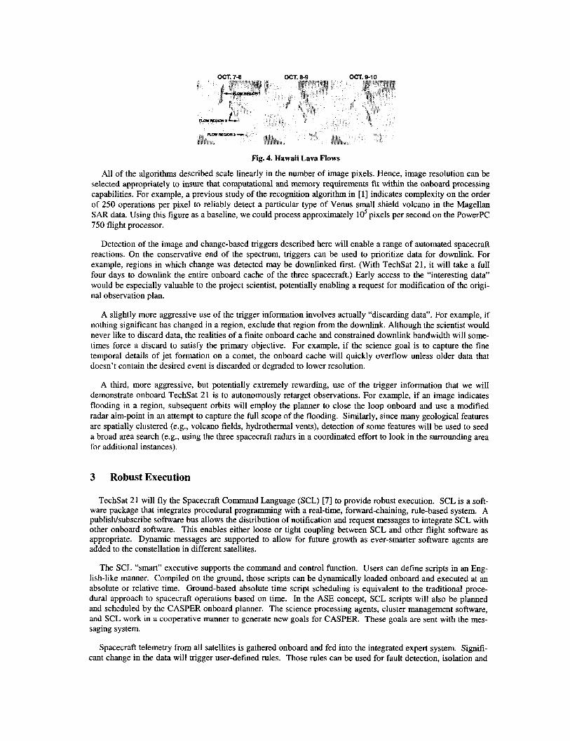
OCT. 7-6 OCT. 8-9 OCT. 9-10
Fig. 4. Hawaii Lava Flows
All of the algorithms described scale linearly in the number of image pixels. Hence, image resolution can be selected appropriately to insure that computational and memory requirements fit within the onboard processing capabilities. For example, a previous study of the recognition algorithm in [l] indicates complexity on the order of 250 operations per pixel to reliably detect a particular type of Venus small shield volcano in the Magellan S A R data. Using this figure as a baseline, we could process approximately lo5 pixels per second on the PowerPC 750 flight processor.
Detection of the image and change-based triggers described here will enable a range of automated spacecraft reactions. On the conservative end of the spectrum, triggers can be used to prioritize data for downlink. For example, regions in which change was detected may be downlinked first. (With TechSat 21, it will take a full four days to downlink the entire onboard cache of the three spacecraft.) Early access to the “interesting data” would be especially valuable to the project scientist, potentially enabling a request for modification of the origi- nal observation plan.
A slightly more aggressive use of the trigger information involves actually “discarding data”. For example, if nothing significant has changed in a region, exclude that region from the downlink. Although the scientist would never like to discard data, the realities of a finite onboard cache and constrained downlink bandwidth will some- times force a discard to satisfy the primary objective. For example, if the science goal is to capture the fine temporal details of jet formation on a comet, the onboard cache will quickly overflow unless older data that doesn’t contain the desired event is discarded or degraded to lower resolution.
A third, more aggressive, but potentially extremely rewarding, use of the trigger information that we will demonstrate onboard TechSat 21 is to autonomously retarget observations. For example, if an image indicates flooding in a region, subsequent orbits will employ the planner to close the loop onboard and use a modified radar aim-point in an attempt to capture the full scope of the flooding. Similarly, since many geological features are spatially clustered (e.g., volcano fields, hydrothermal vents), detection of some features will be used to seed a broad area search (e.g., using the three spacecraft radars in a coordinated effort to look in the surrounding area for additional instances).
3 Robust Execution
TechSat 21 will fly the Spacecraft Command Language (SCL) [7] to provide robust execution. SCL is a soft- ware package that integrates procedural programming with a real-time, forward-chaining, rule-based system. A publisWsubscribe software bus allows the distribution of notification and request messages to integrate SCL with other onboard software. This enables either loose or tight coupling between SCL and other flight software as appropriate. Dynamic messages are supported to allow for future growth as ever-smarter software agents are added to the constellation in different satellites.
The SCL “smart” executive supports the command and control function. Users can defiie scripts in an Eng- lish-like manner. Compiled on the ground, those scripts can be dynamically loaded onboard and executed at an absolute or relative time. Ground-based absolute time script scheduling is equivalent to the traditional proce- dural approach to spacecraft operations based on time. In the ASE concept, SCL scripts will also be planned and scheduled by the CASPER onboard planner. The science processing agents, cluster management software, and SCL work in a cooperative manner to generate new goals for CASPER. These goals are sent with the mes- saging system.
Spacecraft telemetry from all satellites is gathered onboard and fed into the integrated expert system. Signifi- cant change in the data will trigger user-defined rules. Those rules can be used for fault detection, isolation and

recovery. In that case, rules can be used to execute recovery scripts. Another application of rules is for mission constraint checking to prevent operator errors or, more simply, command pre-processing.
SCL is a mature software product, and has successfully flown on Clementine-I and ROMPS. SCL has also been used in a wide range of ground-based control and operations contexts. As such it represents a good basis for integrating the multiple ASE autonomy functions: onboard science, mode identification and reconfiguration, planning, and constellation management.
4 Model-based reconfiguration
CASPER generates a mission level plan that includes a sequence of behaviour goals, such as producing thrust. An executive is responsible for reducing these goals to a control sequence, for example, opening the relevant set of valves leading to a main engine. A device, such as a valve, is commanded indirectly; hence, the executive must ensure that the components along the control path to the device are healthy and operating before command- ing that device. Components may be faulty, and redundant options for achieving a goal may exist; hence, an executive must ascertain the health state of components, determine repair options when viable, and select a course of action among the space of redundant options.
Interpreting sensor information and generating sequences to handle a breadth of novel situations requires ex- tensive reasoning about physical processes and state changing actions. A model-based executive performs this reasoning automatically from an onboard model [ 121. In particular, a model-based executive is given a model of the spacecraft hardware, including a set of component models and a schematic that describes component inter- connections. The executive uses the model to track planner goals, confirm hardware modes, reconfigure hard- ware, generate command sequences, detect anomalies, isolate faults, diagnose, and perform repairs.
The executive receives a stream of hardware configuration goals and sensor information. It uses sensor in- formation to infer the state of the hardware and then continually tries to transition the hardware towards a state that satisfies the current configuration goals. The model-based executive is reactive in the sense that it reacts immediately to changes in goals and to failures, that is, each control action is incrementally generated using the new observations and goals given in each state.
The executive uses its model to determine the desired control sequence in three stages --- mode estimation (ME), mode reconfiguration (MR) and model-based reactive planning (MRP). IvlE and MR set up the planning problem, identifying initial and target states, while M R P reactively generates a plan solution. More specifically, MI incrementally generates the set of most likely state trajectories of the hardware that are consistent with the hardware model and the sequence of observations and control actions. This is maintained as a set of most likely current states. MR uses the hardware model and the most likely current state generated by ME to determine a reachable hardware state that satisfies the current goal configuration. MRP then generates the first action in a control sequence for moving from the most likely current state to the target state. After that action is performed ME confirms that the intended next state is achieved.
Model-based reactive planning is traditionally viewed as intractable for real world problems. We address this intractability through a set of model-compilation, causal analysis, and online policy construction methods. The result is a model-based reactive planner that is sound and complete. It generates the first control action of a valid plan in average case constant time, and compensates for anomalies at every step. Finally, it will not gener- ate irreversible, potentially damaging sequences except to effect repairs.
Our model-based execution framework uses the Mode Estimation capabilities of Livingstone 1 and 2, de- scribed in [9, 141 and developed at NASA Ames. The marriage between the model-based executive and SCL provides a powerful hybrid execution capability with an expressive scripting language and an extensive capabil- ity to generate novel responses to anomalous situations.
5 Onboard Mission Planning
Traditionally, the majority of planning and scheduling research has focused on a batch formulation of the problem. In this approach, when addressing an ongoing planning problem, time is divided up into a number of planning horizons, each of which lasts for a significant period of time. When one nears the end of the current
horizon, one projects what the state will be at the end of the execution of the current plan. The planner is in- voked with a new set of goals for the new horizon, and the expected initial state for the new horizon. The planner then generates a plan for the new horizon. For example, the Remote Agent Experiment operated using this ap- proach [8].
This approach has a number of drawbacks. In this batch oriented mode, typically planning is considered an off-line process, which requires considerable computational effort, and there is a significant delay from the time the planner is invoked to the time that the planner produces a new plan. If a negative event occurs (e.g., a plan failure), the response time until a new plan is generated may be significant. During this period the system being controlled must be operated appropriately without planner guidance. If a positive event occurs (e.g., a fortuitous opportunity, such as activities finishing early), again the response time may be significant. If the opportunity is short lived, the system must be able to take advantage of such opportunities without a new plan (because of the delay in generating a new plan). Finally, because the planning process may need to be initiated significantly before the end of the current planning horizon, it may be difficult to project what the state will be when the cur- rent plan execution is complete. If the projection is wrong the plan may not be executable.
To achieve a higher level of responsiveness in a dynamic planning situation, we utilize a continuous planning approach and have implemented a system called CASPER (Continuous Activity Scheduling Planning Execution and Replanning) [4]. Rather than considering planning a batch process in which a planner is presented with goals and an initial state, the planner has a current goal set, a plan, a current state, and a model of the expected future state. At any time an incremental update to the goals, current state, or planning horizon (at much smaller time increments than batch planning) may update the current state of the plan and thereby invoke the planner process. For the spacecraft control domain we are envisioning an update rate on the order of tens of seconds real time. This update may be an unexpected event or simply time progressing forward. The planner is then respon- sible for maintaining a consistent, satisficing plan with the most current information. This current plan and pro- jection is the planner’s estimation as to what it expects to happen in the world if things go as expected. How- ever, since things rarely go exactly as expected, the planner stands ready to continually modify the plan. From the point of view of the planner, in each cycle the following occurs:
1. 2.
3.
Changes to the goals and the initial state first posted to the plan, Effects of these changes are propagated through the current plan projections (including conflict identifi- cation) Plan.repair algorithms [SI are invoked to remove conflicts and make the plan appropriate for the current state and goals
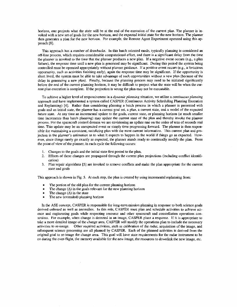
This approach is shown in Fig. 5. At each step, the plan is created by using incremental replanning from:
In the ASE concept, CASPER is responsible for long-term mission planning in response to both science goals derived onboard as well as anomalies. In this role, CASPER must plan and schedule activities to achieve sci- ence and engineering goals while respecting resource and other spacecraft and constellation operations con- straints. For example, when change is detected in an image, CASPER plans a response. If it is appropriate to take a more detailed image of the change area, CASPER will modify the operations plan to include the necessary activities to re-image. Other required activities, such as calibration of the radar, acquisition of the image, and subsequent science processing are all planned by CASPER. Each of the planned activities is derived from the original goal to re-image the change area. This goal will have state requirements for the radar instrument to be on during the over-flight, the memory available for the new image, the resources to downlink the new image, etc.
The portion of the old plan for the current planning horizon The change (A) in the goals relevant for the new planning horizon The change (A) in the state The new (extended) planning horizon

A Stat A Goals
,
Fig. 5. Continuous Planning Incremental Plan Extension
When a new goal is placed on the schedule, conflicts occur for each of these related resources. CASPER modifies the schedule using iterative repair until no conflicts exist [ 161. Operations for modifying the schedule include adding new activities, moving activities, deleting activities, changing activity parameters, etc. Each activity has a list of permissible operations for the iterative repair algorithm. The algorithm is fast, performing several hundred operations per second on a workstation, or a few operations per second on an 8 MIPS flight processor. (The typical response time for ASE is less than 10 minutes to elaborate a new complex goal.) The choice of operations can be guided with user defined scheduling heuristics [17]. The heuristics can be activity specific or generic. An example would be to try moving activities 50% of the time, adding activities 35% of the time, and deleting activities 15% of the time.
6 Observation Planning Software
The Observation Planner (OP) interfaces to flight software that automatically determines the current space- craft position and orbit. This software uses GPS signals to very accurately pinpoint the location and velocity of the TechSat 21 constellation. Onboard, the OP has a potential observation target list. Periodically, it takes the current orbit solution and simulates forward to predict over flights for the next 15 days of each and every poten- tial target. These over flights are then used by CASPER as observation opportunities when planning future sci- ence observations.
7 ASE Software Validation
Because of the significant TechSat 21 mission cost (> $1OOM), and that ASE will be controlling the spacecraft activities, TechSat 21 Management required significant safeguards on ASE development and operations. These safeguards include: analysis of ASE impact on the spacecraft, testing and validation requirements on ASE, and phased operations during actual flight.
First, the project conducted an independent analysis of the ways in which ASE actions could damage the spacecraft. This analysis determined approximately 30 general ways in which inappropriate commanding by ASE could adversely impact spacecraft health. For each of these ways, one or more mechanisms for detecting and preventing such commands were identified and required as part of the baseline experiment and mission de- sign. For example, if ASE kept the radar payload on to long (e.g. did not power it down at the end of a data collect), this would overheat the payload (causing damage to the payload) as well as drain the battery. Both of these potential conditions will be monitored in both SCL and the TechSat 21 flight software. Additionally, this capability will be extensively tested before flight. Therefore the risk of ASE endangering the spacecraft via this interaction is remote. An important point is that a careful log of experiment operations will be kept and any misbehavior by ASE that results in the activation of TechSat 21 fault protection would be considered a failure of ASE.
Second, the ASE software is being extensively validated by: code, scenario, and model walkthroughs as well as testing. We are relying on years of past experience with both CASPER and SCL for basic software function- ality validation. Science software can be unit validating using existing radar data with hown science targets. For the TechSat 21 specific model deployments, we have developed a set of test cases. For each of the software builds, the range of cases covered is defined, designed, and reviewed by cognizant personnel. Additionally, for

each build the software is tested on a wide range of test cases. For build 2, completed in June 2002, there are approximately 3000 test cases in the integrated system test suite.
Third, the experiment operations concept has a phased operation concept designed to build confidence in the system and shake out any remaining issues. In the first phases of the experiment, the ASE software will run in shadow mode, developing plans and commands but these commands will not be sent on to the spacecraft. In this phase ASE will score and evaluate science data onboard but will not be authorized to command the spacecraft based on the data analysis. In the full operational phase of the experiment, the ASE software will replan based on the science analysis and all ASE commands will be sent on to the spacecraft.
8 ASE and Multi-Agent Systems
While TechSat 21 is a multi-spacecraft constellation, ASE is not a multi-agent system. In the ASE architec- ture, the constellation is treated as a single agent, with each of the spacecraft being a redundant subsystem. On one spacecraft, the “master” spacecraft, CASPER is running in order to perform the planning (and replanning) for the entire constellation of three spacecraft. The plans developed on the “master” spacecraft are sent on to the other two “slave” spacecraft. Because of this architecture there is no decentralized coordination problem. While there is significant interest in multi-agent coordinating spacecraft at NASA [13,14], for the TechSat 21 mission, use of a multi-agent, distributed architecture was viewed as too risky for flight at this time.
9 Related Work and Conclusions
In 1999, the Remote Agent experiment (RAX) [ 101 executed for a few days onboard the NASA Deep Space One mission. RAX is an example of a classic three-tiered architecture [12], as is ASE. RAX demonstrated a batch onboard planning capability (as opposed to ASE’s continuous planning) and RAX did not demonstrate onboard science. RAX also included an earlier version of the Livingstone and Burton mode identification and fault recovery software. PROBA [ l l ] is a European Space Agency (ESA) mission that will be demonstrating onboard autonomy and launches in 2001. However, ASE has more of a focus on model-based autonomy than PROBA.
More recent work from NASA Ames Research Center is focused on building the IDEA planning and execu- tion architecture [ 151. In IDEA, the planner and execution software are combined into a “reactive planner” and operate using the same domain model. A single planning and execution model can simplify validation, which is a difficult problem for autonomous systems. For ASE, the CASPER planner and SCL executive use separate models. We have designed the CASPER modeling language to be. used by domain experts, thus not requiring planning experts. In ASE, SCL is running the plan and performing an independent local check of the plan. The “plan runner” in IDEA performs this function although without the validation check. The ASE science analysis software is defined as one of the “controlling systems” in IDEA. In the IDEA architecture, a communications wrapper is used to send messages between the agents, similar to the software bus in ASE. We are unaware of any deployments of the IDEA architecture, so a comparison of the performance or capabilities is not possible at this time.
The Three Comer Sat (3CS) University Nanosat mission will be using the CASPER onboard planning soft- ware integrated with the SCL ground and flight execution software [6]. The 3CS mission is scheduled for launch in late 2003. 3CS will use onboard science data validation, replanning, robust execution, and multiple model- based anomaly detection. The 3CS mission is considerably less complex than TechSat 21 but still represents an important step in the integration and flight of onboard autonomy software.
ASE will fly on the TechSat 21 mission will demonstrate an integrated autonomous mission using onboard science analysis, replanning, robust execution, model-based estimation and control, and formation flying. ASE will perform intelligent science data selection that will lead to a reduction in data downlink. In addition, the ASE experiment will increase science retum through autonomous retargeting. Demonstration of these capabili- ties in onboard the TechSat 21 constellation mission will enable radically different missions with significant onboard decision-making leading to novel science opportunities. The paradigm shift toward highly autonomous spacecraft will enable future NASA missions to achieve significantly greater science returns with reduced risk and cost.

Acknowledgement
Portions of this work were performed at the Jet Propulsion Laboratory, California Institute of Technology, under a contract with the National Aeronautics and Space Administration.
References
1.
2.
3.
4.
5.
6.
7. 8.
9.
M.C. Burl, L. Asker, P. Smyth, U. Fayyad, P. Perona, J. Aubele, and L. Crumpler, “Learning to Recognize Volcanoes on Venus,” Machine Leaning Joumal, April 1998. M.C. Burl and D. Lucchetti, “Autonomous Visual Discovery”, SPIE Aerosense Conference on Data Mining and Knowledge Discovery, (Orlando, FL), April 2000. M.C. Burl, W.J. Merline, E.B. Bierhaus, W. Colwell, C.R. Chapman, “Automated Detection of Craters and Other Geological Features Intl Symp Artijkial Intelligence Robotics & Automation in Space, Montreal, Can- ada, June 2001 S. Chien, G. Rabideau, R. Knight, R. Sherwood, B. Engelhardt, D. Mutz, T. Estlin, B. Smith, F. Fisher, T. Barrett, G. Stebbins, D. Tran, “ASPEN - Automating Space Mission Operations using Automated Planning and Scheduling,” SpaceOps, Toulouse, France, June 2000. S. Chien, R. Knight, A. Stechert, R. Sherwood, and G. Rabideau, “Using Iterative Repair to Improve Re- sponsiveness of Planning and scheduling,’’ Proc Fifh International Conference on Artijlcial Intelligence Planning and Scheduling, Breckenridge, CO, April 2000. S. Chien, B. Engelhardt, R. Knight, G. Rabideau, R. Sherwood, E. Hansen, A. Ortiviz, C. Wilklow, S. Wichman “ Onboard Autonomy on the Three Comer Sat Mission,” Intl Symposium on Artificial Intelligence Robotics and Automation in Space, Montreal, Canada, June 2001 Interface & Control Systems, Spacecraft Command Language, http://www.sclrules.com, June 2002. A. Jonsson, P. Morris, N. Muscettola, K. Rajan, and B. Smith, “Planning in Interplanetary Space: Theory and Practice,” Procs 5th Int Conference on Artificial Intelligence Planning Systems, Breckenridge, CO, April 2000. J. Kurien and P.P. Nayak, “Back to the Future for Consistency-based Trajectory Tracking,” Proc. National Conference on Artcjicial Intelligence, Austin, TX, 2000. Kurien, J. and Nayak, P.P., 2000. Back to the Future for Consistency-based Trajectory Tracking. Proc. Na- tional Conference on Artificial Intelligence, Austin, TX.
10. Remote Agent Experiment Home Page, http://rax.arc.nasa.gov, June 2002. 11. PROBA Onboard Autonomy Platform, http://www.estec.esanl/probaf, June 2002. 12. R. P. Bonasso, R. J. Firby, E. Gat, D. Kortenkamp, D. Miller, and M. Slack, Experiences with Architecture
for Intelligent, Reactive Agents, Journal of Experimental and Theoretical Artificial Intelligence , Vol. 9, No. 1, 1997.
13. S. Chien, A. Barrett, T. Estlin, and G. Rabideau, A Comparison of Coordinate Planning Methods for Coop- erating Rovers, Fourth International Conference on Autonomous Agents (Agents 2000), Barcelona, Spain, June 2000.
14. B. Clement, A. Barrett, E. Durfee, and G. Rabideau, “Using Abstraction to Coordinate Multiple Robotic Spacecraft,” Proceedings of the 2001 Intelligent Robots and Systems Conference, Maui, HI, November 200 1.
15. N. Muscettola, G. Dorais, C. Fry, R. Levinson, and C. Plaunt, “IDEA: Planning at the Core of Autonomous Reactive Agents,” Proceedings of the APS-2002 Conference, Tolouse, France, April 2002.
16. G. Rabideau, R. Knight, S. Chien, A. Fukunaga, A. Govindjee, “Iterative Repair Planning for Spacecraft Operations in the ASPEN System,” Intl Symp on A.I. Robotics and Automation in Space, Noordwijk, The Netherlands, June 1999.
17. R. Sherwood, G. Rabideau, S. Chien, B. Engelhardt, “ASPEN User’s Guide,” http://aspen.jpl.nasa.gov, August 2002.