space.nss.org...-solar power satellite system definition study volume vii phase i final briefing sps...
TRANSCRIPT

6lllllNl6
(NISA-CR-160376) SOLAR POWER SATELLITE SYST!8 DEPIBITION STUD!. VOLUftE 7 1 PHASE 1: SPS AND RECTENMA S!STE"S ANALYSES PiAal Briefing (Boeing Aerospace co., Seattle, Wash.) 280 BC A13/!P A01 ~SCL
NAS9-16638 DRL T·1487 ORD MA·732T LINE ITEM4
I
Phase I, Final Briefing SPS and Rectenna Systems Analyses D 180·26031· 7
NS0-13145 NASA CR·
/(, '? ;.~y,Jz_ .. Unclas 46033
Solar Power Satellite System Definition Study\
6lllllNll
GENERAL. ELECTRIC
Cl .. UMMAN , Arthur D Little Inc. TRW
\ )\
HE C £. \ ''i F.. 0 . , ,., i: r, s·n r 1\c11..m -:i,J j,~, . .,,,,,, a'f '
1\CCtSS DEl- 1• '•,I,
,, :~

- Solar Power Satellite System Definition Study
Volume VII PHASE I FINAL BRIEFING
SPS and Rectenna Systems Analy1e1 D 180-25037·7
Boeing Aerospace Company
Ballistic Missiles and Space Division P.O. Box 3999
Seattle, \\iashington 98124
Approved By: ~J~ G. R. Woodcock Study Manaaer

0180·25037·7
FOREWORD
The SPS System Definition Study was initiated in June of 1978. Phase I of this effort was completed in December of 1978 and is herewith rerorted. This study is a follow-on effort to an earlier study of the same title completed in March of 1978. These studies are a part of an overall SPS evaluation effort sponsored by the U. s. Department of Energy (DOE) and the National Aeronautics and Space Administration.
This study is being managed by the Lyndon B. Johnson Space Center. The Contracting Officer is. Thomas Mancuso. The Contracting Officer's representative and Study Technical Manager is Harold Benson. The study is being conducted by The Boeing Company with Arthur D. Little, General Electric, Grunman, and TRW as subcontractors. The study manager for Boeing is Gordon Woodcock. Subcontractor managers are Dr. Philip Chapman (AOL), Roman Andryczyk (GE), Ronald Mccaffrey (Grunman), and Ronal Crisman (TRW).
This report includes a total of seven volumes:
I - Executive Surrrnary II - Phase I Systems Analyses and Tradeoffs
III - Reference System Description IV - Silicon Solar Cell Annealing Tests V - Phase I Final Briefing Executive Sunmary
VI - Phase I Final Briefing: Space Construction and Transportation VII - Phase I Final Briefing: SPS and Rectenna Systems Analyses
In addition, General Electric will supply a supplemental briefing on rectenna construction.
2

SPS-2525
* 0900
• 1045
1200
• 1300
• 1430
• 1500
• 1530
• 0900
• 0930
• 0945
• 1015
• 1100
1200
* 1300
• 1330
0180-25037·7
Agenda
I THURSDAY,DEC14TH
EXECUTIVE SUMMARY
TOPICAL REPORT I: SPACE OPERATIONS
CONSTRUCTION LOCATION ANALYSIS
(LUNCH)
SATELLITE CONSTRUCTION ANALYSIS
ALUMINUM SATELLITE STRUCTURE
TOPICAL REPORT II: GROUND OPERATIONS
INDUSTRIAL INFRASTRUCTURE
RECTENNA SITING
I FRIDAY, DEC 1&TH
TOPICAL REPORT Ill: SATELLITE a RECETNNA SYSTEMS
SOLAR ARRAYS AND ANNEALING
ONBOARD POWER HANDLING
ONBOARD DATA 8l COMMUNICATIONS
POWER TRANSMISSION SYSTEM
POWER RECEPTION SYSTEM
(LUNCH)
TOPICAL REPORT IV: DEVELOPMENT PLANNING
TECHNOLOGY ADVANCEMENT
FLIGHT PROJECTS
* = VOLUME V
• = VOLUME. VI
• = VOLUME VI I
3 &. 4
G.WOODCOCK
E. DAVIS
K.MILLEA,A.McCAFFREY
A. McCAFFREY
P.CHAPMAN
D.GAEGORY
O. DENMAN
O. DENMAN
A.CRISMAN
E. NALOS
R.ANDRYCZVK
G.WOODCOCK
D. GREGORY

0180-25037·7
STUDY ALUMINUM STRUCTURE
10GWSOLAR POWER SATELLITE
5 &. 6

GROUNDRULES
• LEO CONSTRUCTION 4 BY 8 MODULE 2673 m x 6348 m
• FABRICATION IN DIRECTION OF MAJOR AXIS OF MODULE
• CONSTRUCTION BASE MAJOR AXIS IS EARTH POINTING· CONSTRUCTED IN DIRECTION OF IELOCITY VECTOR
• SOLAR BLANKET PRELOADED UNIAXIALL V
• BEAMS ATTACHED CENTROIDALL V
• FLATNESS REQUIREMENT
7&8

D 180-25037·7
DESIGN DATA
• MASS DATA SOLAR ARRAYS 5.178 x 10⁷ kg MW ANTENNAS 2.521x10⁷ kg
WT GROWTH 2.061 x 10⁷ kg TOTAL 9.75 x 10⁷ kg
• SOLAR ARRAY BLANKET UNIT WEITHT- 0.427 kg/m2
• T/W IN TRANSPORT FROM LEO TO GEO - 0.0001
• SPS NATURAL FREQUENCY INCLUDING SOLAR CELLS & ANTENNAS - 0.0012 Hz
• SOLAR BLANKET NATURAL FREQUENCY - 0.0024 Hz
• SOLAR BLANKET PRELOAD NEEDED TO OBTAIN FAE· QUENCY = 4.285 N/m (0.0245 LB./IN.)
• FACTOR OF SAFETY -1.4
• 30 YEAR SERVICE LIFE
9

0180-25037·7
DESIGN CONDITIONS
The more significant structural loading conditions currently are the.solar array blanket
preload and loads caused by transport of the 4 bay x 8 bay module to GEO. The first condi-
ticn causes a high local cap load in the 7.5 meter beam; the second induces the highest column
compression load in vhe 7.5 m by 667.5 m beam. In as much as aluminum has a coefficient ot thermal expansion (CTE) greater than the advanced structural composites, the effect of gradients
on distortions, stresses etc., are under evaluation. Thermal control features will be incorporated in the design to minimize thermal/structural response. These include thermal coatings, in
corporation of lightening holes in members, etc, !()ads induced <luring fabrication and handling will also require assessment.
10

0180-25037·7
DESIGN CONDITIONS
• SOLAR BLANKET PRE-LOAD
• TEMPERATURES & THERMAL GRADIENT TIME HISTORIES
• TRANSPORT ACCELERATION TO GEO
• ATTITUDE CONTROL & STATION KEEPING TORQUES
• STIFFNESS
• INTERFACE LOADS BETWEEN MODULE & CONSTRUCTION BASE; BEAM HANDLING
I I

0180-25037·7
SOIAR ARRAY FREI.DAD DESIGN CONDITION
The LEO baseline configuration utilizes a four bay wide construction base to fabricate
the 4 bay by 8 bay module. During module construction, the 15 meter wide solar array blankets
are installed on the two end bays of the 8 bay length as shown. The 15 meter arrays are
interconnected along their lengths and unia.xial.ly pretensioned such that the blanket natural
frequency is 8.64 cph. Bending moments, caused by the pretension result in high axial com
pression loads in the caps of the 667.5 m beam. This condition gives the critical load in
the cap.
12

0180-25037-7
SOLAR ARRAY PRE-LOAD DESIGN CONDITION
CONSTRUCTION BASE
DIRECTION Of MAJOR AXIS OF SPS
667.5 m DIRECTION OF PRE·LOADON SOLAR ARRAY
I
---- DIRECTION OF FABRICATION FREQUENCY OF UNIAXIALL Y LOADED MEMBRANE
3600 IT fn = 2r v W cph
£ = LENGTH METERS
S = TENSION PER UNIT WIDTH W = ARRAY UNIT WEIGHT
REQUIRED In = 8.64 cph
13
2873m
-..--,,.

I
0180-25037-7
LOADS APPLIED TO BEAM B, .. SOLAR ARRAY
I
~ MINOR AXIS-...... OFSPS
667.5 m
667.5 m
I
14
"-.1~H I~
...,___ UNIAXIAL PRE-LOAD ON SOLAR ARRAY
~ MAJOR AXIS
~OFSPS
D• ..... MAN .,
0180-25037-7
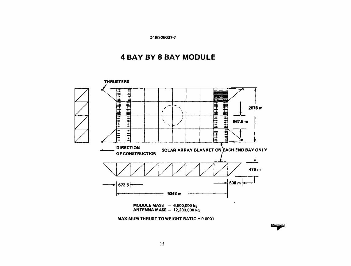
4 BAY BY 8 BAY MODULE
THRUSTERS
~ _!_ 2678m -- -/ ' I \
667.5 m I ,, \ '
DIRECTION -- SOLAR ARRAY BLANKET ON EACH ENO BAY ONLY OF CONSTRUCTION _j_
_l
'\JZIZIZ1Z1Z1ZL?12V 470m
tn.sl• 5348
"' ·1 soomf-f
MODULE MASS - 6,500,000 kg ANTENNA MASS - 12,200,000 kg
MAXIMUM THRUST TO WEIGHT RATIO= 0.0001
15
OSllUMMAN ,

0180-26037·7
MODULE SELF TRANSPORT TO GEO DESIGN CONDITION
The maximum compression load in the 667.5 meter member results from the module transfer
from LEO to GEO. The four thruster forces are applied to the module and antenna masses as
shown in the figure. A ~c magnification factor of 2.0 and a factor of 1 .• 4 are applied
to the member loads. The maximum compression load in the 667.5 meter beam is -7544 lbs.
16

018().25037·7
DESIGN LOADS ON MODULE ./.;.__
.....- 2886 LB
C0'4DITION: SELF-TRANSPORT TO GEO
----11 -LB I
• TOTAL THRUST• 1.8349 x 1o4N (4123 LB, LIMIT • DYNAMIC MAGNIFICATION FACTOR• 2 • FACTOR OF SAFETY• 1.4 FOR ULTIMATE • Foqce PER THRUSTER. 2886 LB • ANTENNA INERTIA FORCE• 7532 LB ULT. • MODULE INERTIA FORCE:• 4013 LB ULT. • ANTENNA SUPPORTED AT POINTS A, B, C, D
17

0180·25037·7
SUMMARY TRUSS LOADS DUE TO ORBIT TRANSFER FROM LEO TO GEO
~ I
I
7.5m BEAMS I (LB ULTIMATE)
NOTE: • PRETENSION UNIAXIAL SOLAR BLANKET LOADS ON UPPER BEAMS DO NOT ACT ON ABOVE MEMBERS. BENDING CAUSED BY SOLAR ARRAY PRETENSION OCCURS ON 7.5 m BEAMS NORMAL TO ABOVE BEAMS.
• INCLUDES MODULE & ANTENNA MASSES
JS
...,,,.

0180.26037·7
VARIATION OF CRITICAL CAP COMPRESSION LOAD VS BEAM DEPTH
MAX MOMENT ON 887.6 m BEAM• 2.98 x 10⁸ IN.·LB ULTIMATE
..
H •
-10
-8
LOAD -8 tNH6 I LB x 103 ULTIMATE -4
-2
0 0------------L 6 10
b METERS 16
19
......,___,.o E---41---t- l 0.0245 LB/IN. !
~0.11611 b-\ I
Mq_ CH, I • - 1.732 b

0180·25037·7
ALUMINUM BEAM DESIGN 7.5 METER
I •
The aluminum triangular cross section beam design incorporates three roll formed cloltfd section
caps interconnected by battens spaced at 7.5 meters. Shear stiffness can be provided by either pre
loaded cross cables or compression/tension members. The cable concept is approximate]¥ 2~ lighter
and has been selected for the baseline alwuinum structure. However, pretensioned cables for shear
stiffening may induce potential problems such as: adjustment of all cable tensions to the proper preloads to prevent slack at any time, failure of cable attachments, potential tor excessive material
creep deformation under sustained load and temperature for 30 years increased by an appropriate scatter factor, effect of selected cable system on lattice colwun capability, etc.
The selected cap size for the design loads is 7.5 inches deep and has a thickne11 of .028 inches.
The batten i& also a closed section with the bottOID flanges extending outward tor attachment to the cap. The depth is 4 inches and thiclaless of 0.020 inches.
In order to minimize thermal gradients in me~bers and between membera, lightening holes have been spaced to reduce shadowing as much as possible. Thermal coatings are also being evaluated to maintain temperatures and gradients within acceptable limits.
The roll formed cap incorporates longitudinal stiffening beads near the corner sections in order
to provide a high compression capability in the corners. Between the lightening holes, beads are
roll~d into the section for stiffening. The section is formed on a mandrel which is used for support
during the attachment operation. The lower attachment on the centerline is not completed until after the battens are connected. The gap between flanges permits the mandrel support to extend inward to
the beam machine; the mandl·el support ends, and the twcfltlanges are joined.
20

0180-26037-7
ALUMINUM BEAM DESIGN (7.5 METERS)
7.6 m CROSS-SECTION
21
f 0.19 m (7.6 IN.)
ROLL FORMED ALUMINUM CAP WITH STIFFFNINO BEADS MATERIAL 2024·T3

0180-26037·7
BEAM CAP SECTION ROLL-FORMED ALUMINUM ALLOY
FLANGED LIGHTENING HOLE IN CAP
I I
22

D 180-25037·7
BATTEN SECTION ROLL-FORMED
y
h
t
"JP'
23

0180-26037·7
CANDIDATE MATERIAL PROPERTY DATA
2024·T3 2219·T6 6061·T8
• FTu ksi 64 54 42
• FTv ksi 47 36 36
• Fev ksi 39 38 35
• Ee ksi 10.7 x 10³ 10.8 x 10³ 10.1 )( 103
• p LB/IN.3 0.100 0.102 0.098
• ex IN./IN.rF x 10-6 @200°F 12.9 12.4 13
• K BTU/(HR) (FT2) (°F)/FT 80 74 96
• C BTUnLB)fF)@200°F 0.22 0.23 0.23
.,,, .. 24

0180-25037·7
ALUMINUM CLOSED SECTION BEAM CAP THICKNESS & DEPTH VS CRITICAL LOAD; L = 7.5 m
Cf.I w :z: u !: :z:" t: &&I c ~
10 0.06 t
8 fl) 0.04 w :z: CJ ! gf -6 0.03 -r w z :llt
. Si h (L' {'f) :z: ....
4 .. 0.02
2 0.01
00=--~-2~~--'c-4----~6--~~,-----~,o----~,~2~--,~,~___,11
PcR LBF x 1o3
25

16 tn
COMpllEBs1CJN. 1EIVS/CJN l>l"IGOJVAl
26
i
WEtG11r1ulV1T LENar,., kg;,,,
1.8

0180-25037-7
PRELIMINARY ESTIMATE OF MODULE SLOPES FOR VARIOUS THERMAL GRADIENTS
1.4
1.2
1.0
0.8 SLOPE 0 DEGREES
0.6
0.4
0.2
0
~T 0 f
0 1 2 4 5 6 3
~METERS x 103 MODULE LENGTH ........... ,.
27

0180-25037-7
ESTIMATED DEFLECTION DUE TO TH~MAL GRADIENT
An estimate of the solar array module slopes and deflections was calculated for various
tem9erature gradients. The analysis was based on the following assumptions:
o The module structure was cantilevered from the construction base.
o The temperature gradient between upper and lower surface did not vary
spanwise.
The results show that for a temperature difference between upper and lower members of
200°F the tip deflection relative to the base is 8 meters; the slope is 0.8 degrees.
Updated thermal data will be used to reevaluate these estimates.
28

0180-25037-7
PRELIMINARY ESTIMATE OF MODULE DEFLECTIONS FOR VARIOUS THERMAL GRADIENTS
120
100
80
DEFLECTION 60 ~METERS
40
20
CONSTRUCTION BASE
1 2
6T°F
3 4 5 6
e METERS x 103 ___ ., , 29

0180-26037·7
ORBITAL A'l'TI1'JDE DURING CONSTRUCTION
Thermal analysis of the construction phase is being performed to yield the &liruct•.iral
te111Peratu~e distribution necessar,v to perform the distortion/stress analysis, Both horizontal and vertical beam orientations will be investigated for the first pa.rt of this study, to minimize thermal grandients, the horif.Ontal beams were oriented so that the axes of the elements were aligned with the sun's rays so th.e:.t the 3un entering the holes in the two sun-facing surfaces 1mpinged on the third (back) at 0° orbit angle (se3 sketch). At the back side ot the orbit (before entering the earth's shadow) sol&r energy enters the •. lea in the back
surf~ce to impinge on the other two.
Other arrangements to be considered are the severe caaea where the sun is normal to one of the ~urfaces at 0° orbit angle and where one element shadows another. The vertical beama where intermittent shadowing taker place, is also to be investigated,
For the construction plw.se, a 300 n. Mi ci=cular orbit is considered,
In GEO-synchronous orbit, the gradient• between the sun-aide horizot.tal beama, and thoae oppositewill be calculated,
For this study, the !nside of th* elementa are coated with black anodi~• (E • ,.83, o( = • 86) and tbe outside au.rtace with Z-93 white paint ( f •. 90, o(. • .17) •
30

0180-25037-7
ORBITAL ATTITUDE DURING CONSTRUCTION
I /~ __ --EB- _NA_D_I~ ---~ o~ ORBIT A~GLE
~- 1__-/ ~ ,__...v
I t ff t t HORIZONTAL BEAM
SUN
-
<l ~ R T
(~ ELEMENT :RIENTATION < ,j AT o'· ORBIT ANGLE
VERTICAL BEAM •'
31&.3::
E A R T H

0180·26037·7
ALUMINUM STRUCTURE STUDY
REMAINING TASKS:
• COMPLETE THERMAL ANALYSES FOR SELECTED ORIENTATION
• EVALUATE STRUCTURAL RESPONSE TO TEMPERATURE EXPOSURE
• COMPARISON WITH COMPOSITE DESIGN
33
. .,,,

0180·26037·7
UPDATED EFFICIENCY AND SIZING
The SPS efficiency chain has undergone two minor revisions during this contract period. The regulation, auxiliary, and annealing power factor of 0.983 is lower than the 0.99 factor used previously. The inter· subarray loss factor of 0.976 is an improvement over the 0.956 factor used 1n the Part Ill System Def1n1-t1on Study.
The changes to the efficiency chain result in a slight decrease 1n the solar cell area requirement (0.6 km2).
34

0180-25037-7
Updated Efficiency and Sizing
---------------------1.----------------------------....---------------------•llllNll----SPS·2435
EFFICIENCY MEGAWATS PER LINK
MAIN BUS 12R
ROTARY JOINT
ANTENNA POWER DISTRIBUTIO~ AND PROCESSING
DG-RF CONVERSION WAVEGUIDE 12R
IDEAL BEAM
0.8:W
1.0
0.97
o.• 0.181
0.88&
INTER·SUBARRAY 0.171 LOSSES
INTRA·SUBARRAY 0.181 LOSSES
ATMOSPHERE LOSSES 0.88
INTERCEPT EFFICIENCY ·o.I& RECTENNA RF·DC o.n
1,878
1,290
8,290
8,041
8,138
8,733
1,417
8,:W1
8,221
l,Ol7
SOLAR ARRAY OUTPUT
TOTALINPU TO ANTENNA
T~TAL RF OWER
P3kttTED
SOLAR INPUT:
SOLAR-CELL CONVERSION EFFICIENCY (0.173)
BLANKET FACTORS (0.84&3)
1,363W/m2
234.1 221.3
THERMAL DEGRADATION (0."64) 211.1
ORIENTATION LOSS (0.811) 194.0
APHELION INTENSITY t0.1876) 117.7
NONANNEALABLE RADIATION DEORATION (0.17) 112.1
ORBIT TRANSFER COMPENSATION (0.99) 180.2 REGULATION, AUXILIARY POWER, 171.2
AND ANNEALING (0.983)
EOL BLANKET OUTPUT:
TOTAL SOLAR-CELL AREA:
SOLAR ARRAY OUTPUT:
171.2W/m2
I0.1 kmZ
l,871MW 15,712 INCIDENT ONRECTENN,,_ ____________________________________ ---'
GRID INTERFACING 0.97 1,111 -0.183 1,000 NET TO GRID
35

0180-26037·7
5000 MEGAWATT REFERENCE PHOTOVOLTAIC SYSTEM DESCRIPTION
The configuration of the 5000 megawatt SPS is basically that of one-half of the 10,000 megawa'tt SPS devel .. oped in the Part III System Def1nit1on Study. This description shows the revised dimensions from the updated efficiency chain, structural resize, and implementation of array shadowing diodes.
Using 12.7 meter beams for array attactvnent necessitated changing the internal bay dimensions to compen .. sate for increased lost area, for 667.5 x 667.5 meter bay centerlines. In addition to this dimension change, the beam/array clearance for the catenary support system was increased from 2 meters to 3 meters at each bay end.
Incorporation of shadowing diodes in the array panels (to be shown on a later chart) created more lost area on the blanket. To compensate for the combined lost are&' effects it was necessary to add two array strings to each bay, one string to each end segment.
36

D 180-25037·7
5000 Megawatt Reference Ph.otovoltaic System Description
---~~S-·2-47_0 __________ _.. ________________________________________________ lllllNO ____ __
__ __. __ __._...._...·~r-e~•1~"1f" TOTAL SOLAR CELL ARIA a 60.1 km2 TOTAL ARRAY ARIA I 63.7 km2 TOTAL IATILLITI ARIA I 67.3 km2
10710 m ..J
tr-~ 4
711m '12.7m BEAM
. 867.&q ..
1 r.1sm
TVPIC.AL BAY 887.&m
6353m I
MINIMUM POWER.TO ILIPRINGI s 8.29 GW
L-I ~7"1 ~~~M CHORD ! ..
-:-~- . . . ... 3m l t r ~ ....... ]
.... ... ~ .... .....
.... ""I ' 4 STRINGS/16m 1
END SEGMENT tN ' "" I
TERMEDIATE SEGMEN 1 I I • ' ~
'
CATENARV
~ . ·1 - ,, 'I' . .
,.
I . ' I
•
EGMENT
NTS/BAY 44-16m SEGME 698 STRINGS/BA 111 PANi LI/IA
v
....
J 1Qcm .L
I ~ ' '
·~
• 1
l--1.11m _j Y ~A INQ LINQTH 11Tf'8Nll/11m IND
llGMINT
37

D 180-26037 • 7
REFERENCE PHOTOVOLTAIC SYSTEM DESCRIPTION
The basic blanket panel configuration has changed slightly. To compensate for the shorter length available within the bay, the solar cell length was degreased from 6.55 an to 6.48 cm. This was sufficient to allow for the 12.7 meter beams and 3 meter catenary support discussed previously.
The only other change that was made to the basic blanket panel was the incorporation of two shadowing diodes (shunts) per panel. Each panel maintains the 16 cells in series and 14 cells in parallel configuration except on the two end rows where there are 13 cells in parallel. The 13 parallel cells will allow only 3 cP.11 failures, instead of 4 allowed by the other rows, and still pass string current without reverse bias operation.
38

D 180-25037 · 7
Reference Photovoltaic System Description
--~s~~-~1M~9--•--14_C_E_L~L-S-IN--PA_R_A_L_L~E-L_W_l-LL--TO_L_E_R_A_T_E-------------.--------------------------•llll~ll----,4 CELL FAILURES IN ANY ROW f
f 16C INS
ELLS ERIES
'
I
II I
TYP. ~.1cm
Q-• II
•
1 .0568m
-7. 44cm
L- 14 CELLS -- \ ~sc:ALE
IN PARALLEL \ ~ SHUNT DIODE
12.5 µm COPPER 10% AREA FACTOR .75x 4cm
INTERCONNECT PATTERN (BACKSIDE) #CELLS/PANEL :222
PANELS/BAY :366,378 PANELS/SATELLITE :9,363,678
CTRICAL RCONNECT
-· I ::1 1.- -. :·l!O
- I --- I ____ , h-I - I
I ..___ I
I - I . -- I
I II - I I ] .. · -
.._~, :::•. -11
l LI
5cm...,. -
39
TAPE 1.6cmx40µm----
LONGITUDINAL TA~E 1.5 cm x 40 µm
L .5cm WELDED /TABS
(13/PANEL)
v a -/ ...... ... ...... - ... :-·" - - -- ·-· .. -... ..
.a
.. -- - - ... ... ...
1.059m
i.. .. :·
- ....
J
. J L115µm
SECT A·A
1.067 m

0180-25037-7
IMPLEMENTATION OF ARRAY SHADOWT~G ~IODES
A large shadow moving across an array string could cause the shadowed cells to operate 1n a reverse-biased mode. This operation can cause "hot spots" (energy consumption instead of generation) and can lead to string failure. To prevent this problem from causing array damage it is necessary to incorporate shadowing diodes to shunt the power around shadowed panels and prevent reverse-bias operation. The rationale and design criteria used to incorporate the shadowing diodes on the SPS blanket are noted on this chart.
Two, redundant, shadowi~g diodes were added to each blanket panel as shown. The electrical equivalent of a blanket panel with the shadowing diodes is also shown. This configuration will protect array panels from reverse-bias operation. The individual parallel sets of cells on the panel receive their protection by the 11 four out of fourteen" cell loss method.
Since the shadowing diodes occupy space that would normally be used for solar cells, an increase 1n the "lost area" of the blanket panel results. If the diodes were placed in another location packaging for transportation penalties would result. Therefore, to compensate for the new 11 lost area", extra array was added to the system with mass end area penalties shown.
40

)
SPS-2434
0.25 SHUNT D
D 180·25037 • 7
Implementation of Array Shadowing Diodes
RATIONALE:
PREVENTS ARRAY DAMAGE CAUSED BY UNEVEN ILLUMINATION AND SHADOWING EFFECTS
PROVIDES MORE GRACEFUL POWER DEGRADATION FROM BLANKET PANEL FAILURES AND SHADOWING EFFECTS
DESIGN CRITERIA:
REVERSE-BIAS PROTECTION FOR BLANKET PANELS
LOW REVERSE LEAKAGE CURRENT
LOW FORWARD-VOLTAGE DROP
HIGH RELIABILITY
COMPATIBLE WITH BLANKET PANEL CONFIGURATION•
59 i--1.0 m 0 cm_._ -114cm
REDUNDANT (PARALLEL) SHUNT DIODES INCREASE IN SYSTEM SIZE • 0.451 km2 INCREASE IN SYSTEM MASS• 192.3 MT
T IODE ~ i
I I 1
.25cm
~SHUNT. t T DIODE-
.J~ - - . . ... . ~ .... ...
I
16CE LLS INSE RIES
6.48 cm 1 cm YPICAL
o.
- ,-14 CELLS
1 IN PARALLEL
T
...... 7. 44cm
- SHUNT DIODE
PHYSICAL ARRANGEMENT OF SHUNTING DIODES ON BLANKE!T PANEL
I
I
I I I
I
I
I
"' . . ... . . .. . . . ... .. ., . - - SHUNT DIODE
ELECTRICAL EQUIVALENT
41

0180-25037-7
SOLAR ARRAY SUPPORT STP.UCTURE EVOLUTION
Illustrated here ~re the original and revised baseline hexahedral solar array support structu;·e concepts. In the original system the edge ce1ls of each of the eight modules making up the entire SPS used the configuration illustrated. The interior cells employed an absolute minimum of structure. Further analysis indicated that the edge cells were not stable with the result that the entire system was not stable. Further9 the 7.5 meter beams were not adequate for solar blanket tension when the solar blanket tension was changed to uniaxial. As a result, the system was revised to the configuration indicated with 12.7 meter beams for solar blanket tension support and all cells incorporating the structural concept shown. The lower-deck-to-upper-deck diagonal provides structural stability.

0180-25037-7
Solar Array Support Structure Evolution
____________ ...;._ ______ -'--------------------------------------------------•llllNO-----Sf>S.2194
970M
ORIGINAL
ALL 7%M BEAMS
l_ __ 1--- 667.5M ~
e NOT STABLE
e 7'hM BEAM INADEQUATE FOR SOLAR BLANKET TENSION
EDGE CELL
43
REVISED
ALL 7'hM BEAMS
EXCEPT AS NOTED

0180-25037-7
SOLAR PORER SATELLITE STRUCTURAL BAY CONFIGURATION
The revised bay configuration including an index of the location and typ~s of beam~ used in a typical bay
is shown. A loads analysis resulted in using three types of beams in the satellite structure. For construction purposes, type B and C beams differ only in their batten spacing. This will allow the use of only two types of beam machines in the ~onstruction facility.
For the SPS constructed at GEO, the type 11811 beams are replaced by type "C".
44

SPS·2473
J 'I
1. i
MODULE STRUCTURE
0180·25037. 7
Solar Power. Satellite Structural Bay Configuration
©, @
,, ./'
,/·' '"' ~: .. ' . : 1i1
/
~/ ©:
45
TYPE "A" BEAMl-12.7M
TYPE "B" BEAMS - 7.&M 7.IM BATTENS
TYPE "C" BEAMS - 7.IM 12.7M BATTENS

D 180·26037 · 7
BEAM CONFIGURATIONS
The three types of beams in the satellite primary structure are shown. Also listed for each type of beam are their section and beam character1st1cs. In previous satellite designs the beams were sized for the "worst case" load condition resulting in a mass penalty on the majority of members which had a s1gn1f1-cantly lower load. This updated configuration has started to reduce that penalty by having three types of members. The savings can be shown by the difference in mass/length between the 12.7 meter, type A, beam and the 7.5 meter, type C beam. The majority of beams 1n the satellite are type C beams.
46

........\ 15.0M y
0180.25037-7
•
Solar Power Satellite Structural Update Beam Configurations
LOADING POINTS CHORD
BATTEN BATTIN IND-CNS
ITEM TYPE A TYPE 8 TVPEC
UPPER SURFACE UPPER AND LOWER SURFACE BEAM USED IN ALL LONGITUDINAL BEAM LATERAL IEAM OTHER LOCATIONS
SECTION CLOSED OPEN OPEN REF. SIDE LENGTH ~CM 38CM 38CM MAT'L THICKNESS 0.88MM 0.71 MM 0.71 MM Elx :S.39 EB N/CM2 1.80 El N/CM2 1.80 El N/CM2
BEAM WIDTH 12.7M 7.6M 7.IM BATTEN SPACING 16.0M 7.8M 12.7M CRITICAL LOAD 17480N (CRIP. CHORD) 19000 N (BUCK. BEAM) 7090 N(IUCK BEAM) MASS/LENGTH 7.48 KG/M 6.12 KG/M 4.11 KOIM
47

0180-26037·7
MULTIPLE BUS SPS POWER DISTRIBUTION
During the critique of the b~se11ne system concept tho system redundancy of the major power system buses were of some concern to both 8~91ng and TRW personnel who accomplished the critique. In addft1on, the potential fault currents that could occur with the sfngle-11ne bus system was also of concern.
A redesign of the main power distribution bus system was accomplished to decrease the poss1b111ty of loss of all power to the antenna and to limit potential fault currents. The overall multiple bus system concept is shown.
48

0180-25037·7
Mult~ple Bus SPS Power Distribution ________ :_ __ .::::;::._ ____ J.. __________________________________________ ~~~··111t1•------
1.1 MEGAWATT DC/DC PROCESSORS (228/ANTENNA) WITH ISOLATION SWITCH GEAR ANPACTIVE · THERMAL CONTROL
ll'S-1212
~ B POWER SOURCE
~---i--AIN B BUSES 4SUPPLY 4 RETURN
..__38,700V TO LIPRI GS
STRING·TO..sTR ING INTERBAV JUMPERS
A POWER SOURCE
I SUPPLY 8 RETURN 40,800 TO SLIPRINQ 1 MM AL SHEET CONDUCTOR PASSIVELY COOLE
I . •
ENTY SLIP RINGS 11 M. MAX. DIA. MUL TIPLI BRUSHES 10A/CM2MAX
STRIP-TO.STA IP TURNAROUND JUMPERS (8 STFUPS • 3 COMPLETE ·
. STRINGS PER BAY WIDTH)
DC SWITCHGEAR ( 2140AMP) EACH STRIP TO MAIN BUI
49

0180-25037·7
MULTIPLE BUS/ARRAY CONNECTION
One of the problems to be addressed in ~: ... ltiple bus system 1s the delivery of power to all sections of the antenna at essentially the same voltage. Shown is a concept that was developed which will enable the delivery of power to the rotary joint w1th the voltage levels for a11 buses within 0.25% of each other which should satisfy d1stribut1on requirements. By staggering the bus connections as shown the voltage delivered only varies by the voltage drop across 1/3 of a satellite bay. The adoption of this multiple bus scheme will result 1n the loss of one quadrant of the antenna for faults on any of the main B source power buses and one-sixth of the antenna for faults on the main A source power buses.
50

SPS·2521
D 18().25037·7
Multiple Bus/ Array Connection
I ,., ,., , ... , I
I I I I I I I I I I
I- -- - --1~ 1• .. J- - -- L -- - - ~---1 : r:~:~~.T~BAY
1 I I 'H I (TYP) I ~ I L ACQUISITION BUS 1
1 MAIN POWER BUS:~ ! (:j 'El~ J.> C'.;il f?PI I
(+t. f.ACH BUS _ - _ _ ____ -i - _ -• ... - . .,.. - - - - .,.- - - - - -+-- TO INDIVIDUAL
~~~~~~~~~~~~~~~~~~~ SLIP RING
i r)- lh I : ;
II C:l ,3 1~1= l:J (_t I SWITCHGEAR I
. CTVP)1 I I . , • l I I I I I
I I I . NOTE: - - - - - - - - - -- 1-•1- .. ·rt - - - - . J_ - -
I I I I I I I .. I ..... I I I ',;# ..
SJ
CONNECTIONS SHOWN ARE TYPICAL FOR ' BA V CONNECTIONS TO MAIN POWER BUSES

0180-26037-7
MULTIPLE BUS CONDUCTOR SUMMARY
This table shows a breakdown of the number of buses for each power source, the number of array power sectors per power source, and the normal bus current per bus for each power source. Also shown is the nunber of DC-DC converters per bus in power source B and the number of klystrons supplied by each bus of each power source.
52

0180-25037-7
Multiple Bus Conductor Summary
SPS-2477
SATELLITE ANTENNA POWER NO.OF ARRAY
B K s SOURCE BUSES POWER SECTORS
A 4 (+) 31 15,988 67 25,388
4 (·J
B 6 (+) 65 22,783 18,925
6M
53

SLIP RING ASSEMBLY FOR NULTIPLE BUS POWER DISTRIBUTION S~STEt1
~Jith the selection of the multiple bus system for SPS power distribution, the requirement for a multiple slip ring rotary joint exists for accomplishing the transfer of power between the power generation (sun-facing) portion and the power transmission (earth-facing) portion of the SPS. A desi~n was developed which provides for twenty slip rings to accomplish power transfer for the ten pairs of power buses.
The concept shown was developed based on the followin~ requirements:
1. Twenty separate slip ring assemblies 2. Normal slip ring current capabilities 3. Maximum brush current density of 10 amperes per square centimeter 4. Brush feeder current density of 400 amperes per square centimeter 5. Brush pressure of 25.9 Kpa (4 psi) 6. Coin silver slip ring (90% silver and 10% copper) 7. Silver-molybdenum disulfide-graphite (85% Ag 12% MOS2 and 3% Graphite) brushes 8. Maximum outside diameter of 16 meters (fits inside HLLV payload bay) 9. Earth assembled
10. Minimum spacing bP.tween different conductor systems of 0.7 meters 11. Positive retraction of the brush assembly from the slip rinq contact surface. 12. All feeder conductors to have maximum surface exposure to free space for thermal dissipation purposes.
54

ONOUCTOR RING (TVP. OF 20)
0180-25037-7
Slip Ring Assembly for Multiple Bus Power Distribution System
55
FOR BRUSH ASSEMBLY SEE DETAIL OWG A
18.0M

0180-25037-7
tt.ILTIPLE SLIP RING BRUSH ASSEMBLY
Details of the brush assembly and slip 19 arrangement is shown.
56

0180-25037-7
Multiple Slip Ring Brush Assembly __________ ..;;... ______ _,_ __________________________________________________ ~! .,,,w•------
SPS-2518 r- 1.1M ---i A,
2.63M
SLIP RING I
SUPPORT ----TRUSS
END VIEW
ALUMINA INSULATOR l ITYPJ
.67M BRUSH HOLDER
(7 BRUSHES EACH SIDE SHOWN,
~~·~~.!r~~-1 UP TO 11 BRUSHES
SLIP RING (TYP OF 20, RADIUS VARIES FOR EACH)
57
I . . :--·s5M-j I . 1.1M--i
I SIDE VIEW

0180-26037-7
ITEMIZED DC/DC CO~VERTER LOSSE$-NEW DESIGN
The critique of the reference concept (task 4.1.1) raised the issue of DC to DC converter life based on corona induced failures within transformers and inductors used in filters. The reference DC to DC converter concept was derived by selecting a converter chopping frequency of 20 kilohertz in order that the overall satellite mass was minimized. However, the reliability analysis was performed using failure rate data based on 400 hertz. Corona-induced failures within transformers are dependent upon the total n1.111ber of AC cycles to which the transformer is subjected. The mean-time-to-failure at 20 kilohertz is 50 times shorter than at 400 hertz.
As a result of the critique7 an analysis was accomplished to investipate the following three approaches to increasing the predicted life of the converter.
a) Reduce the converter system chopping frequency b} Increase the transformer life by derating the dielectric material (i.e., operate at a lower voltage
stress) c) Redesign the transformer to increase its operating life.
Reducing the converter system chopping frequency incurs a significant mass penalty. The converter specific mass including thermal control at 1 kilohertz is approximately 2.9 kg/kw and is approximate1y 1.7 kg/kw at 20 kilohertz. Derating the dielectrics in the converter results in a converter specific mass (including thermal control) of 2.0 kg/kw.
In order to increase the overall converter lifetime dielectrics we· ... e derated for all filters in the converter. The losses for the revised converter are tabulated as a function of frequence in the table.
58

0180-2f;037·7
Itemized DC/DC Converter Losses - New Design
--------------------...,-------------------------------------------------•llllNll___. ~79
LOSSES IN KW AT CHOPPING FREQUENCY CONVERTER SECTION
1 KHZ 10 KHz; 20KHZ 30KHZ
INPUT FILTER 30 . 42 • 54
COND 12 12 12 12 SWITCHING .
SW 2.4 12 24 ~
• DRIVE AND
2.2 I.I 11 11.1 SUPPRESSION
TRANSFORMER 70 70 70 70
RECTIFIERS 2.2 2.2 2.2 2.2
OUTPUT FILTERS 80 120 138 149.1
TOTAL LOSSES 178.8 283.7 30&.2 340.2
EFFICIENCY (%) 98.8 8&.3 94.7 94.1
59

0180.26037-7
DC/DC CO~VERTER SWITCHING FREQUENCY SELECTION
In order to select the chopping frequency for the long life processor, the curves shown were developed for the baselinP. converter design, th~ baseline converter with de-rated dielectrics, and the baseline converter with de-rated dielectrics in all filters and a liquid cooled transformer as a replacement for the baseline transformer. It is apparent from the curves 1r. this ffgure that the minimun mass system occurs when the liquid cooled transformer is used (with de-rated dielectrics in all filters) at a chopping frequency in the 15 to 20 kilohertz range. The converter concept selected to replace the b~seline converter concept is shown a~ the lower of the three curves.
60

0180-25037·7
DC/DC Converter Switching Frequency Selection ____________ .._ ______ .._ _______________________________________________ •1111w11---
SPS-2'13
• MASS• CONVERTER MASS +THERMAL CONTROL MASS +ARRAY MASS ( AEO.UfRED TO MAKE UP FOR CONVERTER LOSSES )
"' ~ c.; -cc ,... w :I z -;
20
18
18
· 14
12
10
SPART II CONVERTER (BASELINE) PART 11 CONVERTER
WITH CERATED DIELECTRIC MATERIALS (TRANSFORMER a FIL TEAS)
PART II CONVERTER WITH NEW TRANSFORMER AND DERATID DIELECTRIC MATERIALS
Q ------'--&. I I I I I
1 2 3 4 & I 7 8 I 10 20 CONVER'TER CHOPPING FREQUENCY .._ KILOHERTZ
61

0180·25037·7
LIQUID COOLED TRANSFORMER
An effort i!. underway by Thermal Technology Labs (t·unded by the USAF Aero Propulsion Laboratory) to develop lightweight transformers for airborne power supr11es. A computer program has been developed, and a 50 KVA prototype fabricated to verify the computer opt1m1zed d~s1gn, to enable the design of lightweight liquid cooled transformers. The computer optimization was used to develop a design for a 6.000 kw liquid cooled transformer. The selected DC/DC converter transformer characteristics are shown in this table.
62

0180-25C37·7
Liquid Cooled Transformer
-----::sn:':'aa&:---------~.._----------------------------------------------••llNll----
POWER IN
POWER OUT
EFFtCIENCV
WEIQHT
INTERNAL SIZE
OPERATING FREQUENCY
63
1110 KW
IMOKW
98.73"-
170 KG
(14 IN)3
20KHZ

0180·25037·7
KLYSTRON MODULE THER~AL cornROL SYSTEM CHARACTERISTICS
A re •is ion to the Part Ill h~at pipe thermal control sy~tem for the klystron module is an active {pumped) thermal ~ontrol system with the characteristics shown on this chart. There are several reasons for the proposed changed to an active thermal control system, but they are highlighted by lower mass and less fault impact.
Using an active thermal control system with the characteristics shown could result in a mass advantage of over 570 MT per antenna. ·
There is a possibility of micrometeoroid penetration or mechanical failure causing a tube leak 1n the radiator of the module thermal control system. Using the heat pipe system of Part III, such a leakage could cause severe, long lasting electrical problems in the vicinity of the radiator leak because conductive fluids were used in the heat pipes. Thus a leak could have contaminated high vcltage electrical insulators with a conductive film of heat pipe fluid. At reasonable pressure, the only heat pipe fluids found to operate in the soo0c temperature range were conductive (i.e., NaK, Hg, CS, etc.).
The active thermal control system adapted for SPS uses air (or Nitrogen) for the high temperature (500°C) section and Dowtherm-A for the low temperature (300°c) section. Both of these fluids are nonconductive.
This work was eccomplisl ~d by Mr. Ray French of the Vought Corporation, an independenf; contributor not under contract on this project.
64

0180·26037·7
Klystron Module Thermal Control System Characteristic.s
--------------------.-.------------------------------------------------lllllllNll----SPS-2412
MATERIAL
FLUID
INLET TEMP
OUTLET TEMP
LENGTH X WIDTH
TUBE SPACING
TUBE DIAMETER
TUBE THICKNESS
FIN THICKNESS
EMISSIVITY
ABSORTIVITY
TSINK
PUMP EFFY.
1=1N EFFECTIVENESS
AREA
MASS/MODULE
rn VOUGl-IT ~ CORPORRTIOri
COPPER
STEAM 0 20 ATM
477°c 413oC
0.57m x 1.81m
3.Jcm
6.8 mm
0.888mm
0.183mm
o.a 0.3
38.JOc 0.3 0.884
0.91 m2
7.96 kg
CURRENT MASS/MODULE - 13.18 kg PART Ill MASS/MODULE - 18.88 kg
65
COPPER
DOWTHERM-A
277oC
280"C 1.04m x 1.e1m
2.84cm
1.27nm
0.71 mm
o.oeemm
0.8
0.3 ae.eoc 0.3 0.920
1.87m2
5.13 k9

0180-25037·7
KLYSTRON PUMPED FLUID THERMAL CONTROL SYSTEM
Shown he~e is the basic layout of the components of the revised active thermal control system !dopted for the klystron module.
66

D\~T'-'bUTION .WAVE'.C::.Ul0£
·. l':nYOUCIH'P D COA .. a .. , •• ,. .. a-"
0180-26037·7
fl~. 7t." I I
KLY~'TM>N
I 1 I
I I, I I
[
PuMP · ACCUtU..A'TOI
. Toa.cut. ,.Utt~ MOTOR.
67

0180.25037-7
BOEING THERMAL ANNEALING TEST DATA
The next three charts show some of the results of a Boeing (IR&O) test program to investigate the possibilities of thermal {bulk) ~nnealing radiation damage from unglassed 50 µ m (2-mil) silicon solar· cells. The unglassed cells were irradiated with 2 MeV protons and annealed in a laboratory oven at the temperatures and times noted. The cells were also subjected to repeated radiation damage and annealing.
The results of these tests are by no means conclusive but do show recovery of radiation damage. It is anticipated that continued work in this area could lead to the optimation of the thermal (bulk) annealing processes for the type of solar blanket baselined for SPS
68

..
0180-25037-7
!o0J!JJJUL7MY@ BPS Thermal Annealing of Proton Damage
78-470
0.4
VOLTAGE (V)
0.3
0.2
0.1
In Silicon: Boeing Test Data
FIRST IRRADIATION
SECOND IRRADIATION
SOLAR EX 50 µm SILICON SOLAR CELL
IRRADIATION:
2 MeV PROTONS
1012 PROTONS/CM2
(-1.5 x 10¹⁶ 1 MeV ELECTRON EQUIV./CM2)
ANNEAL: 500oC
20MIN
0.0 ____ ..__ ___ ..__ ___ "-----.L----J....li-1.._,JL-..U.-
o 20 40 60 80 100 120 CUR~ENT (ma)
69

78-471
0.4 w c.:> <tt-> _,_ 0 >
0.3
0.2
0.1
D 180-25037-7
Thermal Anne:>' Ang of Proton Damage In Silicon Cells: Boeing Test Data
SOLAREX 50 µm SILICON SOLAR CELL
IRRADIATION:
2 MeV PROTONS
1012 PROTONS/CM2
(-1.5 x 10161 MeV ELECTRON EQUIV./CM2)
ANNEAL:
20
soo0c 20MIN
40 60 CURRENT (ma)
80
70
100 120

..
0180-25037-7
IP'/&Jlff §b\Y@Thennal Annealing of Proton Damage In Silicon S'PS' Solar Cells: Boeing Test Data
78-472
0.4 w CJ <Ct-> _,_ 0 > 0.3
0.2
0.1
SECOND IRRADIATION
FIRST IRRADIATION
SOLAREX 50 µm SILICON SOLAR CELL
IRRADIATION:
ANNEAL:
2 MeV PROTONS
1012 PROTONS/CM2
(-1.5x10¹⁶ 1 MeV ELECIS8ft.tcM2 )
450°C 20 MIN.
o.o OL ___ 2.l.0 ____ 4.J..0 ____ 6:':0:------:!':80:-----:1~0:-0 -"--~1~20~-CURRENT (ma)
71

0180-25037-7
FIRST LASER ANNEALING TEST OF A PROTON IRRADIATED 50 pm SILICON SOLAR CELL
The first laser annealing test results for this contract are shown. The cell that was tested was an unglassed 50 µ m (2-mil) silicon solar cell. This cell was irradiated with lxlo12 2 MeV protons/cm2
(~ l.5xlo16 1 MeV electron ~quiv./cm2 ). The cell was then annealed using a 10.6 µ m wavelength C02
laser. The time/tempera· •Jre plots for this test are on the next ctiart.
After irradiation the cell degrad:~d to approximately 74 percent of its initial output. By annealing the cell tht output increased back to 83 percent of its initial power. The small crnount of recovery was considered very good considering the fact that no optimization of the laser annealing parameters was accomplished prior to this test.
72

0180·'.?5037-7
First Annealing Test of Proton Irradiated SOµ m Silicon Solar Cell
-------
5-P~-2f>48 __________ .._ __________________________________________ ,.llllN•-
0.5 f ===============-----==- -------
0.4 AFTER ANNEAL
AFTER RADIATION
~ 0.3 w
~ g 0.2
0.1
0.00~~~~2~0~-----~40~----~~~----~8~0------100L------~1~20----J..--1•40--"----~ CURRENT (mA)
73

0180-25037·7
FIRST ANNEALHIG TEST TEMPERAlURE - TIME DATA
In the flrst attempt to laser anneal a 50 1;m (2-mil) silicon solar cell two heatinq cycles were used.
The reason for this is that; on the first attempt the duration of the laser pL1lse was too short.
The maximum cell temperature achieved was on the order of 4oo0 c. The second pulse, of longer duration,
achieved a cell temperature of sse0c. lhe ti~ that the cell was above soo0c was on the order of
0.5 seconds. Considering the sho!"'t "time at temperature" of thfs test the results are encouraging.
74

D 180·25037."1
First Annealing Test Temperatt.1re - Tilne Data
~$~-,----------.._--------------------------------------------•llllNll--.
POWER DENSITY - 42 W/cm2
# 1 TIME -1.020 SEC
800 # 2 TIME -1.183SEC
-~ w 400 a: a c a: w Q. :r: r.u 200 ...
0 -----~-------~..t...---~--t.~----...._ ____ __. 0 2 4 8 8 10
TIME (SEC)
75

0180-26037·7
LASER ANNEALING CONCEPT
The concept of how the annealing process would be ~'..,.CJri,t'lhhed fs shown. Each laser !1imba1 would have 8-500 watt co2 lasers installed. The laser beams w~•1ld be optica11y Uiilored to provide the desired illumination pattern and P.nergy density.
The gimbals would be mounted on an overhead gantry tnat would span the ent;,·~ bay width, one bay of solar array would be annealed in ftfteen met!r increments. It should be noted t.,.at the solar ~rr~y strings that are undergoing annealing are nonoperational.
76

D180·26037·7
Laser A11nealing Concept
---------------------------------------------------------------------------•OllNll----
667.Sm
~1\~~~~--=---a--aom_c=--=-_-LI' r-!i - - f I
:1
I
I LASER SCANNER TYPICAL-44/GANTRY
DETAIL A TYPICAL 667,6m BAY
77
SATELLITE MODULE ,.,......_,.__.
H-+-+-+-+-+-t-+-+-1-t-t- .r!-187. &m
••m~nn-r&,348m ~~+-+-l_J
ANNEALING GANTRY
I• •! 2,878m
- SATELLITE BAY
DETAIL 8 TYPICAL LASER ANNEALER

018().26037·7
GIMBALLED SCANNING LASER CHARACTERISTICS - UPDATE
As a result of the laser annealing tests being conducted under our current contract and after analyzing the SPIRE annealing test results from the Part III contract, the laser annealin~ power density and amount of equipment has been decreased by a factor of eight. Shown here are the revised laser annealing system characteristics.
78

0180-25037·7
Gllnbaled Scanning Laser Characteristics. Update ------ _...;... ___ .... _________________________ ..,,,, .. -
Sl'S-21157
• ANNEALING ENERGY DENSITY:
• POWER DENSITY:
• TMAX (ACTIVE REGION):
• LASERS/OIMBAL:
• SCANNING SPOT SIZE:
• SPOT SWEEP RATE:
• POWER REQUIRED/LASER OIMBAL:
• POWER REQUIRED/GANTRY:
e NUMBER OF GANTRIES/SATELLITE:
• TOTAL ANNEALING POWER REQUIREMENT:
• TIME REQUIRED TO ANNEAL ARRAY:
79
16 W·t11e/cm2
8 W/cm2
660°C
8
600 cm2 (4'.0 x 11 .4 cm)
6.7 crn/1
26.7kW
1.17 MW
8 (1/SATELLITE MODULE)
IAMW
147 DAYS

0180-25037-7
LARGE FLARE EFFECT ON AR~AY~PERFORMANCE
Results of a statistical analysis of solar flare size are shown. The flare size probability distribution was assumed to follow a log-normal curve. The available statistical sample is too small to develop detailed conclusions as to flare size. It seems unlikely that a log-normal distribution would hold for very large flares since this distribution places no upper limits on flare size.
The two curves shown represent power law and exponential rigidity models for the proton spectrum. Available data fi·t either law about equally, yet these spectral distributions predict large differences in proton fluxes in the energ.v range from 2 MEV to 10 MEV. This energy ran9e is of principal concern for thin solar cells with thi'n covers, but avaflable data do not extend into this region.
Degradation more than 10% from a single large flare is deemed to be highly unlikely. Much improvement in the confidence in this result can be expected due to continued accumulation of statistical data from the current solar cycle and with direct observation of proton fluxes in the 2 MEV to 10 MEV range.
80

0180-25037-7
Large Flare Effect on Array Perf om1ance
----------------------..,·-------------------------------------------------•OllNO--SPS-2275
1.0
0 A.la. 0.9
w' a: 0.8 <C _, u.. w 0.7 z 0 a:
0.6 w ... u. <C
" 0.5 ~ z < 0.4 :E LU a: 0.3 a: w ~
0.2 2 _, <C
0.1 :E a: 0 z 0.0
1.0
LARGEST FLARE SERVED, an2
\POWER LAW MODEL I
I I I I I I I I I I I I I l I
0.1 0.01 J1 0.0001
PROBABILITY OF A FLARE LARGE ENOUGH TO CAUSE ARRAY DAMAGE, PROVtDED A FLARE LARGER THAN 1o6 PROTONS/CM2 OCCURS
81
0.00001

0180-25037·7
DEGRADATION COMPARISON JR ELECTRON IRRADIATION
Shown here is a comparison of the radiation degradation characteristics of the Boeinq/JSC baseline 50 µ~silicon solar cell and the published Rl/MSFC baseline GaAlAs/GaAs solar cell. It can be noted that very little difference in the degradation characteristics can be seen on this plot. This comparison is significantly different than the comparison made in the Rockwell documentation. The data that Rockw~ll used for the 2 mil silicon cell could have been that published in the TRW Radiation Handbook which is not a textured surface cell and shows significantly greater degradation.
For a proper system level trade between the Boeing and Rockwell baselines it i~ n~cessary to resolve the degradation characteristics issue.
82

0180-25037-7
Degradation Comparison For Electron Irradiation
,·• ·-. ---------..a..-----------------------•llllNll--SPS-2452
1.0 r-----------0.9
0.8
0.7
0.6 rvPo
0.5
0.4
0.3
0.2
0.1
ROCKWELL GaA1.:./GaAs SOLAR CELL
BOEING 50 µ. m SILICON SOLAR CELL__..,.-
1014 1015 1 MeV ELECTRON EOUJV. FLUENCE
83

0180-25037-7
DEGRADATION COMPARISON FOR PROTON IRRADIATION
This chart further shows the differences that exist between the two niajor SPS contractors. From this chart it would appear that silicon would have less degradation than GaAs solar cells. It is not being suggested that this is the case, however. The point that is bein~ made is that it appears that there is not a significant difference in radiation degradation characteristics between a SO~m silica· (texturized surface} solar cell and the published Rockwell GaAs solar cell data.
84

0180-25037·7
Degradation Comparison For Proton Irradiation
----------------------.... ------------------------------------------------lllllNO---SPS-2451
1.0
0.9
0.8
0.7
~o
0.6
0.5
0.4
0.3
0.2
0.1
BOEING 60 µm SILICON SOLAR CELLS
(1·10 MeV PROTON All 3750 • 1 MeV ELECTRONS)
ROCKWELL GaA1As/GaAs SOLAR CELL
(1·10 MeV PROTON~ 8600 • 1 MeV ELECTRONS)
1012
10 MeV PROTON FLUENCE
85

0180-25037-7
30 YEAR FLUENCE COMPARISON
Another apparent inconsistency that exists between the two major SPS contractors has to do with the model that is being used to predict the fluence t·:e cell will be subkctt?d to during its 30 years of operation.
This table shows the baseline blankets for both systems in terms of amount of shi~ldinµ afforded in each case. With the silicon being shielded almost twice as much as the gallium system it is doubtful that it could be subjected 1.0 a larger f,11ence unless the environmental models befn~ used are significantly different.
Using the Boeing method for fluence calculations, the Rockwell 5µm GaAlAs solar r.ell equivalent 1-MeV elechon fluence would be approximately 6 x 10 16 instead of the 4.9 x 10 15 shown.
Again, a system level tra~e between the two systems should require both systems to l·e weighed on th~
same scale.
86

0180-26037·7
3() Year Fh~ence Co1nparison __________ ..;. ______ __.i....---------------------------------------------------•11111V11------SP~·2474
ITEM BOEING ROCKWELL
' CELL THICKNESS (mils) 2.0 0.2
FRONT SHIELD (COVER1 BOROSILICATE GLASS A1203 (SAPPHIRE)
THICKNESS (mils) 3.0 0.8
MASS/AREA (g/m2) ie1.e · .. ll.8
BACK SHIELD (SUBSTRATE) BOROSILICATE GLASS FEP/KAPTON
THICKNESS (mils) 2.0 1.8
M.l'SS/AREA/(g/m2) 111.8 .. 72.U
I 30 YEAR FLUENCE 2 x 10¹⁸ • [l> 4.8x 10¹⁵....,.
-~·V ELECTRON EQUIV. /cm2)
[!> BOEING MODEL WOULD PREDICT APPROX. 6x10¹⁸ 1·MeV ELECTRON EQUIV./cm2
87

D 180.26037·7
SPS TELEMETRY REQUIREMENTS
This figure suRll\arizes the telemetry requirements estimated for the spacecraft (solar array) portion of the sato111te up to and including the slip rings, and for the MPTS antenna from the slip rings on. The estimates were prepared by examining the satellite design in detail and estimating the 1nstrumP.ntation required to determine the saiellite state of health and to maka decisions concerning conmands in the event of anomalies.
For those subsystems on which very little design information exists. estimates were made based on knowledge of requirements for typical subsystems of exist1rig 1atel11tes which were then extrapolated to a system n~ the magnitude of SPS.
83

D 180·25037·7
TRW ~-p-~-_T~J-~ M fl. ~J.Jl_~_Q_UJ_~.~kl_~_ N TS.. ____ ...,,, __ SATELLITE SUBSYSTE~ TELEMETRY TYPE ·--······-·--
ANALOG Bl LEVEL
SPACECRAFT
SOLAR ARRAY 89. 152 19.200 ATTITUDE CONTROL & DETERMINATION 26 28
ELECTRIC PROPULSION 656 128 CHEMICAL PROPULSION 112 112
COft'MAND & DATA HANDLING 4,805 9,6i0 CO~UN I CATIONS 30 48 POWER CONTROL 426 204 THERMAL CONTROL 200 400
-----TOTAL 95 ,407 29,730
MPTS ANTENNA
CENTRAL POWER DISTRIBUTION 1 ,648 4'120 P3WER SECTORS 4,560 131,708 KLYSTRONS 970,560 485,280 PHASE CONTROL/RF DRIVE 679,372 388,224 ATTITUDE CONTROL & DETERMINATION 26 28 CONTROL MOMENT GYROS 48 24 COMMAND AND DATA HANDLING 9t194 18,388 COMMU~ I CA TI Qr,.) 30 48 THERMAL CONTROL 200 400
--~---~--
TOTAL 1,665,638 1,028,220
89
DIGITAL
4
24,025 6
12
24,047
1,140
4 24
45,970 6
-·---47, 144

0180-25037-7
SPS COMMAND REQUIREMENTS
Th'is figure surrrnarizes the conmand requirements estimated for the satellite using the same techniques as used for estimatinq the telemetry requirements. This process necessitates many decisions concerning the component level to which each subsystP.m will be instrumented and the level to which a co.11nand capability will be provided. For example, voltage will be measured on each string in each bay and each ~tring will have a conmana disconnect capability at the main po~1er bus.
As these figures indicate, the requirements of the ~· rs are much greater than those of the spacecraft, however, in both cases they are much greater than those of current satellites. The magr.itude of these requirements sugge~t that unusual measures must be taken to keep the data transmission rates relatively low.
90

0180-25037·7
TRW ---·--- SPS COMMAND REQUIREMENTS
SATELLITE SUBSYSTEM
~PACECRAFT
SOLAR ARRAY ATTITUDE CONTROL & OETERMINATION ELECTRIC PROPULSION CHEMICAL PROPULSION COMMAND & DATA HANOLJNG COMMUNICATIONS POWER CONTROL THERMAL C.ONTROL
MPTS ANTENNA CENTRAL POWER DISTRIBUTION POWER SECTORS
TOTAL
ATTITUDf. CONTROL & DETERMINATION CONTROL MOMENT GYROS CO,.,AND AND DATA HANDLING COMMUNICATIONS THERMAL CONTROi.
TOTAL
91
COMMAND TYPE - -------*·-
PULSE STATE
84 1 ,000
224 220
54 90
1,672
1, 140 b~
24 18,388
54
19,690
19,200
32
2,400 200
96 400
22,328
1,848 485,280
32
9, 194
200 400 _____ ..
496,954

018().25037·7
SPS COMMAND & MTA HB_NDLI~.~vsTEM (CDHS) CONSIDERATIONS
The impact of the large numbers of telemetry points and consnands required by the satell lte is to make unsatisfactory the usual practice of sending all data to the ground for information and action. If this practice were followed for ~PS, the data rates would be unacceptably large. In addition the data would either have to be processed, conmands generated and then sent automatically after it reached the grvund or extremely large numbers of ground personnel would be required.
In the recorrmended concept, a large amount of the automatic data processing and generation of predetermined cormiands w111 take place at th! local component level in the satellite, with only sunmary information and configuration changes transmitted to the ground. This concept reduces the amount of data to be transmitted (hence data rates) and also reduces the number of ground personr.el required.
92

0180-25037·7
TRW ____ .,.,.. .... SPS COMMAND & DATA HANDLING SUBSYSTEM (CDHS) CONSIDERATIONS
I CONVENTIONAL TECHNIQUfS (I.E., ALL DATA TO GROUND FOR PROCESSING AND COMMAND DECISION GENERATION) UNSATISFACTORY DUE TO LARGE NUMBERS OF TELEMETRY AND COMMAND REQUIREMENTS
EXTREME AMOUNTS AT DATA THROUGH SATELLITE AND BETWEEN GROUND ANO SATS:.:LLITE
LARGE GROUND CREWS REQUIRED OR COMPUTER AIDED DATA REVIEW AND COMMAND DECISION GENERATION
I RECOMMENDED CONCEPT CHARACTERiCS
PERFORM ROUTINE DATA REVIEW AND GENERATE PREDETERMINED COMMANDS ABOARD SATELLITE WITH MICROPROCESSORS NEAR EQUIPMENT (E.G., LIMIT CHECK DATA ANO SWITCH OFF FAULTY EQUIPMENT)
SE~D LIMITED REAL-TIME DATA TO GROUND WHEN SYSTEM IS OPERATING SATISFACTORILY. ALL DATA AVAILABLE TO GROUND UPON REQUEST.
93

0180-25037·7
PRINCIPAL FEATURES OF CDHS
In order to process telemetry data and generate coll'lllands locally wfthfn the satelifte, numerous microprocessors and memories are required which are distributed throughout the satellite. These processors are organized into groups, each of which is monitored by a processor that is one of another tier of processors. This tiering process continues up to a Centrol Processor Unit which manages the data traffic to and from the ground.
The reco!Tlllended approach fs essentially two systems connected by a limited data link through the slip rings. The reasons for this approach are:
a) The large amount of information which must be handled b) Transmission of large amounts of data at high rates
across the slip rings will be very d1ff1cult c) A redundant link with the ground 1s provided
The use of fiber optics is reco11111ended for data transmission because such a system is of lighter weight, is more fault tolerant (because 1t 1s a non-conductor it does not propogate faults), has a wide-band multiplexing capability, 1s inherently i11111une to EMI ~nd arc discharges, and the raw materials required are in ready supply a~d inexpensive. It is recognized, however, that a considerable amount of development in fiber optics will be required.
A code format which contains the clock has been selected because the long distances over which the data must be transmitted not only make synchronization with a separate clock signal very difficult, but also results in an appreciable increase in complexity and cost.
94

0180-25037-7
TRW -------PRINCIPAL FEATURES OF CDHS
I PERFOR~S SELECTED DATA PROCESSING AND COMMAND GENERATION LOCALLY AB&~RD SATELLITE USING TIERED SYSTEM OF MICROPROCESSORS
• CON~ISTS BASICALLY OF TWO SYSTEMS, ONE FOR SPACECRAFT, ONE FOR MPTS ANTF.NNA, WITH LIMITED DATA LINK THROUGH SLIP RINGS
I EACH SYSTEM HAS SEPARATE GROUND COMMUNICATION LINK
I UTILIZES FIBER OPTICS FOR DATA TRANSMISSION ABOARD SATELLITE
I UTILIZES CCDE FORMAT, SUCH AS MANCHESTER II BI-PHASE CODE, WHICH INCLUDES THE CLOCK
95

0180-25037-7
SPACECRAFT CDHS USING FOUR TIERS OF PROCESSORS
The spacecraft CDHS shown utilizes four tiers of control including the Ce~tral Processor Unit (CPU). The tiers for monitor and control of the solar array are organized in the same order. as the solar array. At the lowest tier (4), each RTU monitors and controls t\'lo of the 100 strings which constitute a load sector. At the next tier (3), each processor (load sector controller) monitors and controls 50 of the lower tier RTU's plus the other load sector functions. The next tier (2), of processors (module controllers) monitor and control 48 load sector controllers and interface with the CPU. Thr. other spacecraft sub:iystems require a relatively small number of RTU's, hence there are only three 1~vels of control, with module controller #3 interfacing directly between the RTU's and the CPU.
The CPu manages data traffic to and from the ground, formats telemetry for transmission and checks commands for bit errors. Other fl'.nctions of the CPU include maintaining stored commands for operating and testing the data subsystem in the absence of ground control an1 control of telemetry data storage for later transmission.
Each tier monitors operation of the tier below, instigates check on subordinate units and establishes priority for upward con1nunication. The lowest tier interfaces the CDHS to other subsystems through sensor readings, digital data transfers and command outputs. An upper tier may also override a command by a lower tier in order to restore o~eration or diagnose apparent failures if its information on the status of the RTU involved, or infonnation from another RTU, warrants such action.
96

TRW 0180-25037·7
SPACECRAFT CDHS USING FOUR TIERS OF PROCESSORS
' CTWICALl •TU - llTU - REllDTE TEMllHL UllT
CllDS TLM
- - llTU'1 RHUIRED FH IOLAR ARRAY - I RTY'1 lllUlllED FIR llllMNIDlll If •ACICRAFT
97
ATTITUDE CDllTROL/ ...... &. ....
TIER · 1 Ciiijiji PMC•R
DRIVE lllTIUI .... RIHI
11111-1
Jlll-J CIDTRl ... NI ••
Cl•liliCAfilil Cl rsn••• IATA--
Dll-t
.1111.

0180-25037-7
MPTS ANTENNA CDHS USING FIVE TIERS OF PROCESSORS
The MPTS antenna CDHS requires a five tier system not only because of the much greater telemetry and co11111and requirements, but because much quicker response is required by the power sectors and klystrons of the MPTS in order to prevent extensive damage in the event of an anomaly. The RTU's (5), monitoring these components monitor fewer sensors but sample them at nearly twice the rate of the spac~craft RTU's. Simularly, at the next level above the RTU's, the RTU controllers {4), monitor fewer RTU's but sample their outputs at a higher rate.
Tiers (3) and (2) provide communications management and test programs for the subordinate tiers except in the case of module controllers #4 and #5 which monitor and control the antenna subsystems other than the MPTS. For these subsystems the number of RTU's is much smaller because of the lower requirem~nts. As in the case of the spacecraft the number of intermediate tiers is reduced for the poftion of the CDHS associated with these subsystems.
98

D 180..25037·7
TRW MPTS ANTENNA CDHS USING FIVE TIERS OF PROCESSORS
atHI: llTU - lllMTI Tll••Al U.tT llTU CHT -- llTU C1111'1MUH
RAFT IllL:.J.. CllJMI. ,...,,
Jtll-1
--- --- --- --- --"'- --- ---- 1---- --- -
{
I IUl llODUU CDllTillLUlll UMIR llOOUU CONTROL URS #I. llfl, #J UI llTU COlfTllOUIM
W•RTU'1
99
IMll-f

0180-25037-7
COMMUNICATION SUBSYSTEM CHARACTERISTICS
Separate systems for the spacecraft and MPTS antenna are reco1T111ended not only because there are separate CDHS systems which must co1T111unicate with the ground, Lut because the nature of the system mission (i.e., continuous provision of electrical power to the grnund) demands high reliability which suggests this redundance.
Alterr-ative systems considered for MPTS co11111unication were u~.e of the retrodirectiv~ beam for the co11111and uplink and modulation of the output of one of the klystrons for the downlink. Both of these techniques have certain advantages, how~ver, since in the event of a relatively minor attitude control system deviation the MPTS antenna beam is deliberately desooiled, the result would ~e severe degradation of the conmunication link at a critical period of operation. For this reason a separate antenna whil~ provides earth coverage is reconmended.
As the figures indicate, the necessary performance is readily provided by an S-Band system using a 20 watt transmitter.
100

0180-25037-7
TRW _ ..... ,,..,_..-
COMMUNICATION SUBSYSTEM CHARACTERISTICS --~~~~~~~~~~~~~~---
I SEPARATE SYSTEMS FOR SPACECRAFT AND MPTS ANTENNA
I EACH SYSTEM HAS 2 FOOT PARABOLIC ANTENNA PROVIDING EARTH COVERAGE GAIN OF 18 dB AT S-BAND
I SPACECRAFT SYSTEM ALSO HAS OMNI-ANTENNA FOR COMMAND RECEPTION IN EVENT OF LOSS OF ATTITUDE CONTROL
I TELEMETRY DOWNLINK CAPABILITY 1-10 MBPS (1 REQUIRED) AT 2.2-2.3 GHZ
I COMMAND UPLINK CAPABILITY 1-5 MBPS (1 REQUIRED) AT 2.05-2.15 GHZ
I KLYSTRON WIDE-BAND NOISE,..,,,,,, 40 dB BELOW COMMAND RECEIVER THRESHOLD
101

0180·26037·7
SPS COMMUNICATION SUBSYSTEM
This figure shows the reconmended subsystem and its interface with the CDHS. This system is very similar to existing S-Band systems hence most of the components are currently available. Information to date indicates that little or no development will be required for an SPS conmunfcat1on system.
102

TRW 0180-25037·7
SPS COMMUNICATION SUBSYSTEM
COMMAND DEMODULATOR
IASEIAND ASSEMBLY
NIT
COMMAND DEMODULATOR
IASEIAND ASSEMILV UNIT
S-IAND RF.CEIVER
S-IAND RECEIVER
S-IAND TRANSMITTER
20WATTS
S-IAND RECEIVER
S-IAND TRANSMITTER
103
OMNI ANTENNA
OIPUXER
WACECRAFI
Mell !~Ilf~N!
DIPLE>'ER
EARTH COVE RA IE ANTENNA 'DISH

D 180-25037·7
CDHS FAILURE MODES AND EFFECTS ANALYSIS RECOMMENDATIONS
The status of hardware design of the CDHS is such that it was not possible to make such an analysis at the hardware level, however, a preliminary system analysis was made. This analysis resulted in the processor redundancy recommendations shown. At the RTU level it was recommended that the data be distributed among the RTU's such that the condition of a component can be determined from the data on two different RTU's. For example one RTU can monitor the on/off switch position of an electrical component. The temperature of that component could be monitored by another RTU. In the event one RTU failed, the status of that component could still be determined from the data of the remaining RTU. This technique also provides for a cross-check by the next level processor monitoring the RTU's.
This analysis also was an important factor in the recommendation to use fiber optics as well as the provision of earth-coverage antennas and the omni antenna.
104

0180-25037·7
TRW _. ........ ,_ ... CDHS FAILURE HODES ANO EFFECTS ANALYSIS RECOMMENDATIONS
I PROCESSOR REOUNOAH~Y
PROCESSORS IN STANDBY REDUNDANtY AT CPU ANO MODULE CONTROLLER LEVEL
BANK OF SPARE PROCESSORS AT LEVELS BETWEEN RTU'S ANO MODULE CONTROLLERS
NON-REDUNDANT RTU'S - REDUNDANCY PROVIDED BY DATA DISTRIBUTION
I DATA BUS
USE FIBER OPTICS
REDUNDANT PARALLEL BUS BETWEEN MODULE CONTROLLERS AND CPU
I PROCESSOR POWER SUPPLY - USE BUS WITH LOCAL REGULATION
I SATELLITE/GROUND COMMUNICATIONS - USE WIDE BAND (EARTH COVERAGE) ANTENNA
105

0180-25037·7
ELECTROMAGNETIC INTERFERENCE SOURCES CONSIDERED
The sources listed are considered to be the most likely sources of internal EMI. Very preliminary consideration of these sources indicated that corona effects and inrush currents were likely to be less severe sources than the others. Since it is not planned to operate high voltage disconnects unless the power h~s been interrupted previously by circuit breakers it was felt that this source would be less than would otherwise be the case. The status of information on slip rings of the size considered here and on 70 Kw klystrons is such that analysis would be of little value at this time.
Since some data is available on the DC/DC converters, and since they are a continuous EMI source, this source was selected for analysis. This very preliminary analysis indicated that the mean electric field at a distance of 6 meters from the conductors would be 20 volts/meter at 20 Khz, declining at higher frequencies. Current equipment must be designed for 10 volts/meter from 14 Khz to 35 Mhz. The mean magnetic f"ield at the same distance would be 36 milliamperes/meter at 20 Khz. The current requirement on equipment is 2.6 microamperes per meter.
106

TRW
0180-25037-7
ELECTROMAGNETIC INTERFERENCE SOURCES CONSIDERED
* I DC/DC CONVERTERS
I HIGH VOLTAGE SWITCH GEAR
I ROTARY JOINTS
I CORONA EFFECTS
I INRUSH CURRENTS
I 70 KW KLYSTRONS
* SELECTED FOR ANALYSIS
107 &. 108

0180·25037-7
SPS·2558
MPTS Phase I Review
109
Erv Nalos Decftl'lber 1978

0180·25037·7
MPTS STUDY AREAS
Primary areas of emphasis in Part 4, Phase I, SPS Microwave Power Transmission System studies were
in the three areas defined on the attached chart. The first two high leverage items contribute
to the baseline design verification, and the third item, due to its potential impact on r.f.
transmitter reliability, offers a viable alternate SPS design worthy of refinement.
110

D 180..25037-7
SPS-:1'556
• PHASE CONTROL :
• FAIL URE ANALYSIS
• SOLID STATE SPS
111

0180-25037-7
MPTS PHASE CONTROL
The major accomplishments in the phase control area are su1T111arized on this chart. A comprehensfve dialogue has been established through the SPS Program Office with Lincom Inc., the designer of the baseline phase control system. A number of circuit refinements and model simulations were carried out to arrive at an improved compromise design.
The failure analysis of a 4 node system defined in conjunction with General Electric Space Division was accomplished, yielding a 3.8% efficiency degradation due to MPTS system availability.
Initial definition of a fiber-optic cabling system was defined in a supporting IR&D effort, yielding a ~·ot~ntial 20:1 reduction in phase error due to cable temperature fluctuations. LaboraicrJ verification is required using coherent and possibly non-coherent GaAs LED's.
112

0180-25037-7
MPTS Phase Control ------------------------.._-------------------------------------------------------~llEl~I;----SPS-2507
e PHASE CONTROL CRITIQUE • CIRCUIT IMPLEMENTATION • COMPUTER PROGRAM VERIFICATION • DISTRIBUTION TREE LAYOUT
e FAILURE MODE ANALYSIS • BASELINE SYSTEM DEFINED • REDUNDANCY LEVEL DEFINED • IMPACT ON EFFICIENCY
e FIBER OPTIC CABLING FEASIBILITY • CONCEPT AND LINK CALCULATIONS
113
0180-25037-7
SPS ARRAY COMPUTER SIMULATION
rn the computer simulation area, routine use is now being made of the "Tiltmain" array program in checking grating lobe levels with systematic and random tilt. The 11 Modmain 11 program, which overcomes some of the storage limita~ions of Tiltmain is now 65% complete, and will ultimately enable modeling the SPS array to the klystron module level (100,000 elements). The program flow of each are indicated or the attached chart, and the status of each is indicated below.
o "TIL TMAIN" Phase Control Verification Grating Lobe Levels, Tilt
·o 11 MODMAIN 11
Capability to Access NASA-JSC Computer Set up files for main program and subroutines
Modmain wiil have the following features:
o Capability to model the spacetenna down to the power module level without excessive storage requirements.
o Incorporation of variable spacing between modules. o Capability to define level of phase control. o More accurate modeling of grating lobe behavior
So far "Modmain" has been matched to a no-error "Tiltmain" run for a 10 m x 10 m subarray and plan fur· Phase 2 is to:
o Incorporate the "error" subroutine i:ito "Modmain" and match to Tiltmain runs.
o Detail the model by chan9ing tre size and spacing of the modules. There will be ten different si;:es of klystron modules corresponding to the ten step quantized illumination taper.
I 14

0180-25037-7
Computer Program Flow Comparison __________________________ ........ _______________________________________________________________ ~111.-11V11------
SPS..2559
l~(lllADI
llCCITI ALL SU9AllllAYS
IHCOllPOllATI I AlllOllS 6 TILT
ISTOAll
l'ICK Otll QllOUND l'OINT
CALCUl.ATl,ATTIAN .--------t CONTIUIUTIOH AT UCH
OAOUNO POINT
PM>CHD TONllCT POINT
NO
MINT ILICTlllC
"'t.0
~LCULATI l,,ICIENClll
AINT IHICllNCIU
''MOOMAlfl" 'llOOllAM 'L.OW CHAllT
115
,.oc rro TO llUT ll()OOL[
lllM (RUii l
"Cl 'llOUllO '°lllTS
ucm 110011u
lllCOA~Tt ( .. OltS I TILT
CAlCUUTl PATTl::J· COllTRllUTIOll loT •11~11
GHIUllO 'I> I llT
"'"' nrcra1c FIELD
CM.CULATl l HI C IUC US

0180-25037·7
GRATHIG LOBE LEVELS.
Typical grating lobe level amplitudes are illustrated a5 a function of distance frorr the rectenna. The design requirement of 1 arcmin. of systematic tilt are derived from these, to meet the Soviet microwave level standard at the first grating lobe. The random tilts have only second order effect on grating lobe levels and affect or1mar11y the array scanning loss.
ih~ baseline 1 arcmin. random tilt, combined with the above systematic tflt, t11ll ccmbine to give a 0.5:~ efficiency loss for a 10 m x 10 m subarr~y. Going to a 5 m x 5 m subarray would allow the tilt requirement to be relaxed to 2 ar~m1n. systematic and 2 arcm1n. random for the same scanning loss of
G. 5~.
116

5'1-1170
, 2
-20 •
0 • -30
• 0
dB DOWN FROM A • MAIN -40 BEAM ll
t 441.5 t 0.5 km
-80 0 1,000
0180-26037·7
Grating Lobe Peaks Produced by Systematic Spacetenna Tilt
3 5 8 7 a 9 GRATING LOBE NUMBER
• • •
0 • •• Cl • • - 4•cmin
0 • Cl
CJ • 0 O - 2.amln • • ll •
ll • • - 1nmln
A ll- O.lnmln
2,000 3,000 4,000
RECTENNA RADIAL DISTANCE IN KILOMETERS
117

0180·26037·7
COMPARISON OF ARRAY
PERFORMANCE DEGRADATION WITH TILT
A number of "Tiltmain' runs were made to check some available aspects of the L1ncom "Solars1m" program, of which the attached curve 1s typical. For the use of a 10 m x 10 m su~array, both one d1m~ns1ona1 and two dimensional "T11tma1n" runs cht::cked we11 with the L1ncom results, provided that surface irregularity error were accounted for in a similar manner.
I 18

0180-25037·7
Comparison of Array
Performance Degradation with Tilt __________________ ...,.._ ________________________________________________ •llllNll------
100 ...---------------------------------
4x4m
as---------------------------------0 2 4 6 8 10
SYSTEMATIC TILT IN X·AXIS, ARCMIN
119
LEGEND
-- LINCOM RESULTS
•
31rcmln SYSTEMATIC Y TILT 3 1rcmin RANDOM TILT (1 o)
Sumce ' • .01~ (48 mils)
BOEING ''TIL TMAIN" RESULTS
(D 3 1rcmln SYSTEMATIC TILT
3 V2 1rcmin RANDOM TILT
@ 3 V2 1rcmin SYSTEMATIC TILT
3 VT 1rcmin RANDOM Tl LT
@ 3 "5 ercmin SYSTEMATIC TILT
3 ''T 1rcmin RANDOM TILT
SurflCI f • .01~ conrmpond1 to 1/2" power IOll

D 180·25037-7
EFFECT OF PHASE ERROR AND TILT ON BEAM SHAPE
From the designer's point of view, it is important to estimate the effects of various phase control
system errors near the rectenna. The attached chart does this in a qualitative manner. One
fallout is the fact that correlated phase errors may not be of great importance in a system that
has more than, say, ten branches per node.
120

0180-25037·7
Effect of Phase Error and Tilt on Beam Shape
----------------------...1-----------------------------------------------------11111111/Vo----SPS·2529
J >
PHASE ERROR BUILDUP
• UNCORRELATED ERRORS .
•CORRELATED PHASE ERRORS
• FEW BRANCHES (4) AT FIRST/SECOND LEVEL
• MANY BRANCHES
ANTENNA TILT
•SYSTEMATIC TILT
• RANDOM TILT
121 & 122
EFFECT
•NO EFFECTS ON MAIN BEAM SHAPE
• FAR·OUT SIDELOBE LEVEL PLATEAU INCREASED
• SLIGHT RANDOM WANDER OF MAIN BEAM BEAM BROADENED BY 4%(95% CONFIDENCE)
•PROBABLY NEGLIGIBLE
•MAIN BEAM SHAPE UNAFFECTED BUT POWER REDUCED BY SCAN LOSS WHICH APPEARS AT GRATING LOBES
• MAIN BEAM SHAPE UNAFFECTED; RESULTING AMPLITUDE MODULATION CAN RAISE ERROR PLATEAU

0180-25037·7
SPS-2557
• Failure Analysis
• Impact On Efficiency
123

0180-25037-7
POTENTIAL PHASE DISTRIBUTION TREE LAYOUTS
The detailed layout of the phase distribution system will depend on the results of a trade study of correlated and uncorrelated phase error buildup per node; redundancy/reliability/ and level at which phase control is exercised. The nine node system ~uffers from poor reliability, poor phase randomization (.e., resulting correlated phase errors which produce beam pointing errors) and lowest tllowable phase error per node. The four node system may be a viable candidate if 10 m x 10 m subarrays are retained and phase control is exercised down to the klystron level. ~three node system may be possible if phase control is exercised at the subarray level only, and subarray size is reduced to 5 m x 5 m.
To reduce phase correlation effects, i.e., beam steering errors, the number of branches at the lower levels should be kept high. This a1 so allows higher random phase error per level in the error budget. Even with 4 m x 4 m subarray, the 4-level system will require a total {1 GHz) phase accuracy of 2° per level to achieve a 96% efficiency including tilt. This will require stringent design criteria. A possible 3 m x 3 m subarray could be accommodated by a 32 x 16 x 16 x 8 four node distribution system. Phase error buildup affects only far-out low level sidelobes, i.e., does not constitute a major environmental problem.
124

SPS.2361
. 0180-26037·7
Potential Phase Distribution Tree Layouts
e 4-NOOE SYSTEM - 7,220 SUBARRAYS, 100,000 KLYSTRON MODULES
10 m SUBARRAY 9.5db TAPER
4:1@ EDGE (6.9 m AV. CABLE LENGTH)
5 m SUBARRAY ...,._,__....,. KLYSTRON MODULE 9.5 db TAPER """"~:=::::;;""'"""'"
32
• 9 NODE - 4 BRANCH SYSTEM
262, 1·44 ELEMENTS
--
125
/ ~,-
~--.............

D180-250:-S7-7
FOUR NODE PHASE DISTRIBUTION SYSTEM LAYOUT
Three sections are shown of the 4 node system selected for reliab111ty analysis by the General Electric Co. This layout uses 20 triply redundant sections at the ffrst level, 19 doubly redundant paths at the second level, and 19 non-redundant paths (cable and electronics) at the third level (i.e., 7220 subarrays). The fourth level provides power dividers down to the klystron module (4:1 at the center and 36:1 at the array edge), to accorrmodate the quantized 10 db Gaussian power taper indicated in the chart.
126

• GENERAL ELECTRIC
0180-25037-7
LOCATION OF REFERENCED PHASE REPEATER STATIONS OF SECTORS AND GROUPS
llVEL l1
I I I I
r/Je20
127
apace division
r ,.J

0180-25037-7
RELIABILITY CALCULATIONS
The MTBF values assigned to each component in the phase distribution path are indicated. These values, together with the redundancy level selected, and the selected maintenarce procedure assumed, lead to availability numbers detailed in the Part 4, Phase 1, Final Report, Dec. 14, 1978, General E1ectric Space Division. The ove~all impact of the failure analysis on efficiency i~ summarized in the table below.
Availability,%
Phase Control .989
Klystron & Driver .98
Rectenna .984
Efficiency, n
.978
Previous Budget
.984
3.8%
5.1%
Comment
Power & Beam Loss Redundant 1st, 2nd Level Conjugator, Receiver 6 Months Maintenance
No Redundancy 25 Year M7BF 6 Month Maintenance
Diodes Nonredundant No Maintenance
DC Panel Open/Short Circuit Continuous Maintenance
Picrowave Related
Total MPTS
Mote that for the phase control system failure, there is a double penalty: arr~y thinning (%availability), and associated loss of power, since the klystrons are not radiating in the main beam direction. The 5.lr:~ fiqure includes efficiencydegradationdue to bussbar failures on the space antenna arid the rectenna.
128

• GENERAL ELECTRIC
PILOT SIGNAL INPUT OF ANTENNA
I I I
.0005
REF ANT.1
REF ANT.2
REF ANT.3
.001
DIPLEXER
.01
.a,,
OUTPUT OF GROUP
.UOl
.015 .283"4 OF ANTENNA .0119
-~~l_j ~:~ER -L~ (cASLE
FAILURES ARE SHOWN IN ONE FAILURE PER lo6 HRS UNITS
I
0180-25037-7
BLOCK DIAGRAM FOR RELIABILITY CALCULATIONS
10Cl'll. OF ANTENNA
I .015
rHASE ,.
129
.0129 .001 tSt LAYER CABLE
PHASE
PO~lEO
OUTPUT OF ANTENN/
I
••
I .UOCIS I RADIATING
- I ELEMENT _, I I I I
space dvlelan
.11112
.001
DIP LEXER
.IJ8

0180-25037-7
KLYSTRO~ MODULE LAYOUT
For purposes of illustration, a 1ayout of the klystron module fs indicdted. It shows possfble
locations of the solid state phase control modules for good thermal distribution. The selection of
a p11ot receiving antenna has not been finalized and is indicative of an a~proach to be considered
to at' 'eve good isolation in a system in which th~ power Deam and pilot beam are at the same
frequency. The radiator is indicative only and is not representative of an alternate lower mass
active co~11ng system under consideration.
130

• GENERAL ELECTRIC
0180·25037·7
OF A TYPICAL MECHANICAL LA ~~~~HE OUTER RING
KLYSTRON MOF.DSUP~CE ANTENNA OF TH·
l3l

0180·26037·7
KLYSTRON M0DUL~ THERMAL CONTROL SYSTEM
CHARACTERISTICS
Failure analyses also indicated a problem with the heat-oioe-cooled klystron. The difficulty was
that the snn°c seQment would utilize a mercury vapor heat pioe. In the event of a meteoroid
puncture or other leak, the 11qu1d metal would be released into the h1gh voltage environment of the
transmitter system and lead to arcing and damage. Plating of liquid metals on insulators might
lead to a permanent damage sftuatfon that would require repair and replacement. Vought Corporation
examined a circulating fluid cooling option and found that a mass reduction was possible and that
fluids could be selected that w'uld minimize risk of &r~ing. Their analysis indicates that a
circulating fluid system can be made as reliable as the heat pfpe system and certainly more reliable
than the expected lifetime of the klystron themselves. The facing page shows principal features of
the circulating fluid system for the klystr?n cooling circuit,
132

0180-26037·7
Klystron Module Thennal Control System Characteristics ____________________ .._ _________________________________________________ ,,,, ..... --
SPS-2472
MATERIAL
FLUID
INLET TEMP
OUTLET TEMP
LENGTH X WIDTH
TUBE SPACING
TUBE DIAMETER
TUBE THICKNESS
FIN THICKNESS
EMISSIVITY
ABSORTIVITY
TSINK
PUMP EFFY.
'FIN EFFECTIVENESS
AREA
MASS/MODULE
00 VOUGl-iT ~ CORPORRTIOh
COPPER
STEAM 0 20 ATM
477oc
413°c
0.&7m x 1.81m
3.Jcm
6.8mm
0.888mm
0.183mm
0.8
0.3 3&.3oc
0.3 0.894
0.91 m2
7.96 kg
CURRENT MASS/MODULE - 13.18 kg PART Ill MASS/MODULE - 18.88 kg
133
COPPER
DOWTHERM-A
277oC
280oC 1.04m x 1.81m
2.84cm
1.27mm
0.71 mm
o.oeemm
0.8
0.3
38.a0c 0.3
0.920
1.87 m2
6.13 kg

D 180·26037· 7
ANTENNA WAVEGUIDE MATERIAL
Although the plated composite approach is probably a high risk based on today's knowledge because
of potential breaks or delamination of the plating under thermal cycling or high RF power conditions,
the cost advantages of a low-coefficient-of-thermal-expansion material are sufficient that develop
ment of a suitable such approach for waveguides should be 1dent1f1ed as a priority development item
for SPS.
134
. ' .

0180-26037·7 ~.::.''
~~. Sps~/~
Antenna Waveguide Material
----------------.....1i.....----------------------------------------111,No----, ."5-2431
•Low CT&plated composite detuning loss is 0.2% compared to 1.3% for aluminum.
• Cost of 1 % efficiency loss is $75 million per 5-GW SPS.
• Plated composite as high-risk, based on today's knowledge.
•Recommend using low·CTE characteristics for waveguide performance and mass; flag development of suitable material as high-priority research item.
135

0180-25037. 7
COMPARISON OF LOSSES FOR METAL AND COMPOSITE WAVEGUIDE
Included in the analysis of aluminum structural options was the analysis of use of aluminum for the
waveguides in the transmitting antenna. Aluminum has a high coefficient of thermal expansion com
pared to the graphite used in the earlier baseline. As a result, due to expected temperature changes,
the aluminum waveguides will be significantly detuned resulting in power losses as tabulated on the
facing page.

0180·25037·7
Comparison of Losses for Metal & Composite Wa_veguide
--------------------...... ----------------------------------------------•1111w11---SPS·2512
.. l
e AVERAGE STICK• 2.78 METERS
e AT• 66°<:
-PERCENT POWER LOSS
ALUMINUM COMPOSITE
STICK LENGTH .87 .02
STICK1
WIDTH .42 .12
CROSS GUIDE LENGTH .17 .02
CROSS GUIDE WIDTH .11 .03
1.37% .19%
137

0180-25037-7
COMMENTS ON NOMINAL EFFICIENCY CHAIN - MPTS
The effect on the overall MPTS efficiency is sunvnarized for the case of aluminum waveguide and the
baseline tilt requirements. (1 arcmin systematic tilt to control grating lobe levels, and 1 arcmin
random tilt to limit total scanning loss to .5%). The additional efficiency reduction due to metal
waveguide and failures in the baseline design is (1.18 + 3.8) = 4.98% for the 10 m x 10 m subarra~'
if tilt remains as above. Further refinements in the rectenna subsystem efficiency values are
indicated as subject for Phase 2 studies.
138

0180-25037·7
Comments on Nominal Efficiency Chain-MPTS ------S-PS--~-,-o----------.... -------------------------------------------------•1111No-----
e CURnENT BUDGET BASED ON COMPOSJ'rE WAVEGUIDE
e SYSTEMATIC TILT 1.75 ARCMIN, NO RANDOM TILT
EFFICIENCY DEGRADATION
10M X 10M 6MX5M
ALUMINUM WAVEGUIDE 1.18% 1.18%
{ 2 ARC MIN SYSTEMATIC J TILT 2.7% 0.5%
2 ARC MIN RANDOM·
RECTENNA TBD TBD
FAILURES 3.8% 3.8%
~n 7.68% 5.48%
13Q

0180-25037-7
FIBER OPTIC CABLE FOR PHASE DISTRIBUTION
rhe potential advantages of a fiber optic cable f~r phase distribution are indicated, possibly with
the use of a coherent laser emitter or a non-coherent LED emitt~r. The elements are identified
below, with a sample link calculation.
140

~ S~~jl
p "./~
0180-25037-7
Fiber Optic Design Considerations for SPS Phase Control Distribution s ~
____________ __;;;._ ______ .&..----------------------------------------------------•Dl~ND----SPS-2555
• INCOHERENT LIGHT EMITTING DIODE
• ONE EMITTER CAN ILLUMINATE BUf~DLE OF >100,000 FIBERS
• REDUt~DANT LED EASY TO IMPLEMENT
• MUL TIMl)DE GRADED INDEX FIBER
• LOSS OF 10 DB/KM COMPATIBLE WITH SPS ($6 PER METER)
• POTENTIALLY GOOD RADIATION RESISTANCE
• CABLE RUNDLE E! 2.5" FOR DUAL FIBER REDUNDANCY (-200,000 FIBERS)
• SAMPLE LINK CALCULATION
POWER DIVISION LOSS E! 55 db
FIBER LOSS E! 5db
FOR 1 mw RADIATED POWER, RECEIVED POWER IS• -60 dbm • 1 nwatt
AVALANCHE DIODE RECEIVER WILL HAVE S/N > 20 db 0 THIS LEVEL FOR 5 MHz BANDWIDTH.
141

0180-25037-7
FIBER OPTIC DISTRIBUTION SYSTEM CONCEPT
A potential layout, suitable for accommodating up to 200,000 fibers is indicated, illuminated by a
LED or semiconducting ( GaAs) 1 C'S er array of several mi 11 iwatts output.
142

0180-25037-7
;Fiber Optic Distribution System Concept
f IF REFERENCE SIGNAL Q @CENTER ARRAY
I 1\ A
I;\\ I; \ \
I I \ \ I I \ \
I
>----HEMISPHl:f.1CAL SECTION 61 CABLES, 226,981
200,000 .005"
'~ D • d (.94 + V ~ ) • 2.27"
\
' '
REDUNDANT ARRAY OF LIGHT EMITTING DIODES (20 DIODES 0.1 mw EC (20 DIODES 0.1 mw EACH TYP.)
HEXAGONAL BUNDLE CONTAINS 61 HEXAGONS (.045" DIA) EACH WITH 61 FIBERS J.005 EACH)
5 MILS EACH
KEVLAR BUFFET TUBE (61 CABLES)
, ----- CONSTANT LENGTH FIBER OPTIC CABLE
3721 FIBERS
61 FIBERS
30 OROUPS OF 2 FIBERS
·~ AVALANCHE DIODE ENVELOPE DETECTOR
RECOVERED IF REFERENCE SIGNAL
143

D 180-26037 · 7
COMPARISON OF COAXIAL AND FIBER OPTIC SYSTEM
A comparison of phase delay for a conventional cable and fiber optic cable indicates a potential reduction in phase chage of nearly 20:1, as well as cabling mass and cost reductions.
144

0180-25037·7
Comparison of s 's - Coaxial and Fiber Optic System
----------------------.... --------------------------------------------------•llllAIO----SPS-2276
COAXIAL CABLE I OPTICAL FIBER
LDF·50 FOAM DIEL. RG·58 SOLID DIEL. (1/2 DIA) ~MIL DIA (66 "m ACTIVE CORE)
ATTENUATION 180 db 36 5 db/km (100 Milz)
MASS 43 160 .6
kg/km
COST 2,000 4,200 1600 (1978) $/km
PHASE DELAY 120°/METER 1800/METER o t1F .. 100 r'1Hz (P1.0, A9""3m) <.-1.5 ).r2m> -
LtrJEAR 18.6x 10⁻⁶/k 5.5x10"7 /k EXPAN,)ION (COPPER) (QUARTZ)
PHASE CHANGE FOR ee.1° 4.46° ~T·45o0c L•300m
145

0180·26037·7
SOLID STATE DEVICE ASSESSMENT FOR SPS
Progress in Part 4, Phase I, emphas1zed areas dealing with:
o Device Assessment . GaAs FET . Sw1tthed Mode
Initial Noise Analysis
o Power Module Concept . Strip L1ne Cavity Radiator • Low Loss Combiner . 3-Stage Ampl1f1er Design
o SPS Integration . Subarray Layout . SPS S1z1ng Trade Study
Power Cond1t1oning In1t1ated . Initial Relidb111ty Assessment
146

0180·25037·7
Solid State Power Amplifier
--------s~-.-23-05------------...a.------------------------------------------------------•llllND------
FINDINGS
• IDENTIFIED A PRACTICAL ELEMENT/SUBARRAY DESIGN APPROACH
• SOLID STATE TRANSMITTER IS A MASS/AREA SYSTEM RATHER THAN A MASS/POWER SYSTEM
• G1A1 FET'S HAVE ADEQIJATE PERFORMANCE-80% EFFICIENCY IS A REASONABLE EXPECTATION
• EFFICIENCY AND THERMAL CAPABILITY YIELD A MAXIMUM TRANSMITTER RATING OF ROUGHLY 2.5 GW GROUND OUTPUT AT ~.4 km DIA.
• EXPECT SIGNIFICANT RELIABILITY ADVANTAGE
ISSUES
• ELIMl~JATION OF POWER PROCESSING
• EXPERIMENTAL MEASUREMENT OF INTEGRATED DEVICE/CIRCUIT/ RADIATOR PERFORMANCE: EFFICIENCY, GAIN, NOISE, HARMONICS
• DEVICE COST (NOW - $100/WATT IN LOTS OF 100)
147

0180-26037·7
SOLID STATE CW POWER STATUS
The device selection of a r,aAs Field Effect Transistor (FET) was based on a thorough review of the
state of the art of var1ous so11d state devices, discussions with NASA-JSC, RCA, and other industries.
The power leval of 5 watts per device is considered realistic for the SPS time frame
148

0180·26037·7
Solid State CW Power Status-1978
SPS-2262
SINGLE PACKAGED DEVICES LE OE ND
100 ... - - 2 TERMINAL DEVICES
IMPATT-MUL Tl·MESA
IMPATT ~
10 GUNN <10%
CW POWER.
WATTS 3 TERMINAL DEVICES (TRANSISTORS) fJ
1 01AIMESFET ""'67"
SILICON BIPOLAR ~
.1 1 2 6 10 20
FREOUENCV,GHz
149

0180-25037-7
SWITCHING AMPLIFIER STATUS
To achieve efficiencies in excess of 70%, it will be necessary to consider the switched mode of
operation where efficiencies in excess of 90% were obtained below 100 MHz. The implementation of
these techniques at microwave frequencies will have to be accomplished as part of a proposed
experimental task.
150

EFFICIENCY:
ACTIVE DEVICE:
0180-25037·7
Switching Amplifier Status
> 96% AT 10 MHZ > 90% AT 100 MHZ
CAN USE BIPOLAR TRANSISTOR OR FET
MICROWAVE IMPLEMENTATION
NEEDS LABORATORY VERIFICATION
MICROSTRIP WITH COMMERCIAL FET INTO TERMINATION
MEASURE EFFICIENCY, SPECTRUM, AND SENSITIVITY TO POWER SUPPLY VARIATIONS,
151

0180-25037·7
SOLID STATE DEVICE LIFETIME
The failure statistics indicated in the attached chart show that at a channel temperature of 135°c,
98% of the devices will still be operat·ing after 30 years. This suggests that a no-maintenance mode
of operation may not be unfeasible. Even if a single FET failure in a power module consisting of 8
output FET's (say 4 w~tts each) constituted a total loss of the entire module (no graceful degrada
tion), the o~eration of such modules at 125°c would result in 2% loss after 30 years, compatible with
SPS failure rate budget.
152
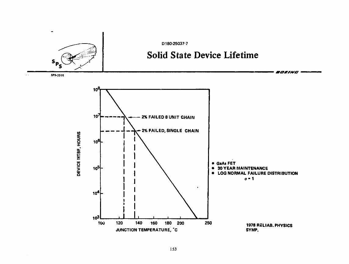
SPS.2311J
en a: :::> 0 ::c u." m .... :: w u > w c
10
1a4
0180-25037-7
Solid State Device Lifetime
----1 - 2% FAILED 8 UNIT CHAI~'
2% FAILED, SINGLE CHAIN
• G1A1 FET • 30YEAR MAINTENANCE • LOG NORMAL FAILURE DISTRIBUTION
o•1
1()3.__ __ _._ ...... ---i~--.-...--------'---_...--~ 100 120 140 160 180 200
JUNCTION TEMPERATURE, °C
153
260 1978 ReLIAB. PHYSICS SVMP.

0180-25037-7
SOLID STATE DEVICE MATURE INDUSTRY COSTING
With a 70% production rate improvement curve (i.e., units produced at the rate of 2n per year cost
70% as much as units produced at the rate of n per year), cost per unit power for GaAs FETS is about
the same as the projected cost per unit power for klystrons.
154

0180-25037-7
Solid State Device Mature Industry Costing
----------------------&.------------------------------------------------llDllNG------SPS-2326
102
~ <( :I: a: 10 w CL 41>
t;-0 (.)
1 ~ u. -(.) w CL (I)
10·1
10·2 ..__ __________ _.....""'-"~~-----.......... --~-------....... ~-102 1a8
NUMBER OF DEVICES PER YEAR
155

0180-25037-7
SOLID STATE SUBARRAY LAYOUT
A proprietary module was identified in an associated IR&D program, in which low-loss combining in
a cavity type microstrip radiator was achieved. Such a module would use F. three-stage amplifiers
with a 5 watt output stage, totaling 30 watts per module. Further module feasibility tests have
been proposed.
A subarray would consist of 144 panels, each panel consisting of 3 strings in parallel, each string
consisting of 12 rows in ser~es, and each row of 4 modules in parallel. The subarray would operate
at approx. 2 Kv and radiate 622 Kw of r.f. power.
156

0180-25037-7
Solid State Subarray Layout ~ SpS~:~
----~S~PS~-2~5~~--.....;·_/ ______ __.L.... ____________ _.. _______________________________________ •DllA'G------
30W POWER MODULE 15V. 59 >. X .59 >.
ROW• 4 MODULES IN PJ\.RALLEL
11' D'E,'0 _EJ 0 0 [ -~ , ..._o_o_· _o_o_.· 1--o_r -4-----1 ·- --------.:-:::
0 0 0 0 ,D C1 ~ ~-0 D 0 o'O 0 r:- PANEL•3STRINGS/
. O O D D " r IN PARALLEL / .59 >. 1· J 0 D D LEAST REPLACEABLE
(.867M) UNIT 4.32 KW
JJ 180V
~7~~A~G
I
.. .. i } -
-
1. 85 A (10.4M) ---1
85). (10.4M)
l ~ .69 A (.867 M) -----1
STRING .. 12 ROWS IN SERIES SUBARRAY • 144 PANEL MATRIX LEAST SWITCHABLE UNIT
MASS ESTIMATE 2.16 KV. 622 KW. 442 KG
COMPONENT MASS PER UNIT AREA (KGM-2;
A 1203 DIELECTRIC 1.99
A I, INCLUDING RADSHIELD 1.39
PHASE FEED AND INTRASUBARRAY STRUCTURE .70
MPTS SECONDARY STRUCTURE .72
MPTS PRIMARY STRU<(TUBE .07
TOTAL 157
4.87

0180·25037·7
SOLAR PO~ER SATELLITE BEAMING NOMOGRAPH
A nomograp:~ has been dev~loped as a useful design tool to determine potentidl solid state SPS design
parameters. For an 20''. eff1cierit GaAs FET and a device temperature of 125°C., a themal limit of
3-5 Kw r.f. radiated per m2 is indicated. A nominal desig~ of 2 Gw with~ 1.~ krr. diameter space
antenna corresponds to this value, for the ionospheric heating limit of 23 rrrt1/cm 2 and the nominal
SPS efficiency chain. Uniform illumination would not be of any advantage in such a design.
I Sf

Solar Power Satellite Beaming Nomograph
15 D2 RECTENNA OIA .. lun
10 9 8 7 6 5 4 3 2.5 2 :i' r n · r Ill 1 1 ti 1 · 1 r 11 ·1111 11 111n1 11 1 ·1111111 ~ 4001 I I I I I I I I ! I I I j I I I I I I • I I I I ' I
• QUANTIZED 9.5 db GAUSSIAN POWER TAPER I 1 1 I I • SYNCHRONOUS ORBIT, 2 45 GHz · · • NOMINAL SPS EFFICIENCY CHAIN
-· I I I I I I ! I j I I I i I I I I I I I I I I I I I I I I I I I f I ' I! I I
''° CJN.AXIS RECTENNA • POWER DENSITY. f>i IONOSPHERE
l -1cm2 ~ ! I • 0.
I ' .I ~ •' I YI J\ I \1-.. '-. 't\}"~ '\°\ \. \. "\. i ! I I I
a z Ill Q IC
I 2i I I 0 -
• ~ v.
~ IC
I N U'I
5 10 0 (.)
"' "':" z • ---~-
...., z .. s Iii
~ • -~
~I I I I I I I i ''IS I'~ ~ ' . ! f' . . < iii~~i~ ! v:: !±t THERMAL
i'JTPU1 I Mt I I I I I I I I I • I I I ... i;\tl'Cf~ll>N~ .. <'~1>nr ~ ,·o GRIO. o·
1
GaGAWATTS ~
UI I I I I I I I I I • I I I f7"'i I l"d f P'l i I I l i 11" I I I I I I I I I I I I
.. ,. ft ' I I I I I I I • I I ' M 11 ' I I I I I I I I I I I I I I 1 I I I I I I I ' I
u u 0.7 a.a Cl..9 1 1.5 2 2.5 3 4 5 D1 SPACE ANTEPINA DIA.. 1cn1

0180-25037·7
COMPARATIVE CALCULATION OF GROUND NOISE
A preliminary noise analysis near the op~rat1ng frequency does not indicate a sign1f1cant advantage for the solid state de~ign, since good oscillators are about at the same level of -160 dBc/Hz as ar~ electron tubes of the klystron type. It is, however, possible to spread this ground noise over a larger area, since the solid state module can be made smaller than a klystron module, and the noise is incoherent (i.e., radiates independently from each module). The attached table shows calculations of the type made by NASA-JSC for the klystron, and indicates a leve'I 14 dB lower for the solid state design for the parameters chosen. Harmonic radiation was not considered 1n this analysis.
160

~~* s ~-·. t
0180·26037·7
Co1nparative Calculation of Ground Noise P5 /~
--------------..;..-------'-----------------------------------------------------•1111.w•------SPS-2351
SOLID STATE
GN • 4nAN/>.2• 308
N • .5 COHERENCY FACTOR AREA• (7>t)2
NOISE SPECTRAL DENSITY• PNGN/4nR!
P' • 7x10·21 WATTS/m2/Hz • -201.5 dbw/m2/Hz
EXTERNAL FILTER CAN PROVIDE ADDITIONAL ATTENUATION
\6\
KLYSTRON
GN • ~~~.;'!~AV. AREA PER KLYSTRON
P' • 1.64JC1o·19 WtTTSlm2/Mf • ·187.4 dbw/m /Hz
MULTIPLE CAVITY DESIGN PROVIDES 24db/OCTAVE ATTENUATION

0180·25037·7
INCOHERENT NOISE POWER DISTRIBUTION
The footprint of the incoherent noise contribJtions is indicated and compared with that of a klystron module.
162

0180·25037-7
Incoherent Noise Po\ver Distribution
------------------..a--------------------------------------------IOllNO ____ _ SPS-2346
I I
I I
I I
I
;' I
I
I
I
I
KLYSTRON DESIGN-6 GW, 1 km
CENTER MODULE FOOTPRINT 3.1° (1.73 m)
EDGE MODULE FOOTPRINT 1.ZO (5.2 m)
~SOLID STATE-2.6 Gw, 1.4 km
, 4.32 Kw PANEL GROUP FOOTPRINT '\ t144-30WATT UNITS)
"'. 7° (.85 m)
'\ '\
2300lcm _ "-
f----...--...:.-~r-------~~ .............. "Boo1c " _J m .-._ RECTENNA 1000 '\
200o lrrt1 ~
163

0180-25037·7
SOLID STATE POHER SUPPLY OPTIOllS
Solid state devites suitable for microwave power amplification operate at voltages on the order of
25 volts. Distri.•ution voltage!:. su'itable for SPS application range from 20,000 to 40,000 volts.
If it were necessi1ry to process all this power down to a voltage of 25 volts, the cost and efficiency
of power processi11g cornbined with the r2R losses and condlJctor mass for such operatfons might be
orohib)tive. Therefore, an approach to elimination of power processing is highly desirable and
constitutes the first option identified, Qirect ~-igh Y,oltage DC (DHV DC). An aspect of this approi'lr.h
is series-parallel connection of the microwave power amplifier". (as regards DC power supply) similar
to that used for solar cells in generation of the DC power. Aggregate sets of microwave power
gener,Jtors can then be supplied at comparatively high distribution voltages. Thi'; option raises
concerns regarding stability, matching, and balance of the power supply and control network.
The minirr.um risk option is use of DC/DC converters but this will result in significantly greater
SPS mass and cost.
AC pm-1er· distribution may provide a means of minimizing distribution losses and reducing solar
array voltage. Mass and c.ost penalties will be similar to those for full DC/DC processing.
164

~ _,,<}:· .. ------, ....
S ~~~ P~ .. /~
0180-25037·7
Solid State Power Supply Options s ........ rr
..... _. ......... _. ............................................................................... ,,IVD ....... .. SPS-2542
e DIRECT HIGH VOLTAGE DC
REQUIRES SUBARRAYS IN SERIES
CONNECTION TOPOLOGY A PROBLEM
HIGH E-FIELDS NEAR ADJACENT SUBARRAYS
MAY CA•JSE ARCS, WILL SUSTAIN THEM
e DC-DC CONVERSION rJN MPTS
PERFORMANCE PENALTIES DC·DC CONVERTERS ~ 1kg/kw POWER LOSSES IN CONVERTERS
SERIES/PARALLEL CONNECTIONS WITHIN SUBARRAYS STILL REQUIRED
e AC POWER DISTRIBUTION
CONVERT DC/AC ON SOLAR ARRAY AC/DC AT SVBARRAY
REQUIRES SIP TO SOME EXTENT ON SUBARRAY
165
SOLAR ARRAY
SOLAR ARRAY
SOLAR ARRAY
DC/ACt---~
I I , . I
11 11
DC/DC
AC/DC
AC/DC

D 180-25037-7
SERIES - PARALLEL INTERCONNECTION
RELIABILITY ASPECTS
The assumptions for an initial reliability analysis are stated and concerns dealing with
AC trar.sients and stability are defined for further effort.
166

0180-25037-7
~~&4 ~--_7 Series -Parallel Interconnection
SpS /~~ Reliability Aspects --------------.;....------..A..--------...-.-----------------------------------------1611ND------SPS.2450
• Direct current reliability
• Single or double failures must not take system down
•Adequate reliability if devices can take 20% overvoltage
• Tum-on transients • Strinp of panels like transmigion line
• No problem with ,,. > 10·6 s
• Alternating current stability
• Oscillations due to coupling between modules • Suppress via damp~ng
167
I I --~ t)oo..-----.-.- -T

0180-25037-7
STRING RELIABILITY ANALYSIS CONFIGURATION
The string configuration is defined for the reliability analysis as consisting of 96 amplifiers,
in 12 rows of 4 modules, where each module has 2 output amplifiers, each with3 output devices.
168

0180-25037-7
String ReliaJ·. ~.1ty Analysis Configuration
----------------------.... ---------------------------------------------------•1111wo------SPS-2553
SERIES STRINGS OF 12 ROWS
4 MODULES PER ROW
2 AMPLIFIERS PER MODULE
SINGLE AMPLIFIER FAILURE PROBABILITY• Fp
.... 1-.t--------- x 8 _______ _.,. .. 1
IF > N AMPLIFIERS PER ROW FAIL STRING GOES DOWN
DESIRED RESULT IS STRING FAILURE PROBABILITY, Fs
AS A FUNCTION OF Fp AND N
REWORK DESIGN UNTIL Fs << Fp
169
x 12

0180-25037-7
SERT~S - PARALLEL STRING FAILURE
The initial results of the reliability analysis indicate that, for the case where 2 amplifiers per
row may fail and still maintain an acceptable overvoltage, the string failure rate can be made much
lower than the amplifier failure rate for cases where the amplifier is highly reliable. For example,
the probability of string failure is lOX lower than amplifier failure at Fp ~04. This will be
even more dramatic for lower Fp's.
170

0180-25037-7
~ s ~~t'
---------P~s:._ __ ~~·=-------1---------------------------------------------------•1111wo------Series-farailel String Failure
SPS-2502
1
.1
PROBABILITY OF STRING FAILURE
F5
.01
1 AMPLIFIER MAY FAIL
2 AMPLIFIERS MAY FAIL
'---------------_.. __ __. ______________ .. ~·~ __ .._ __________________ .,, .001 .01 .1
PROBABILITY OF AMPLIFIER FAILURE f p
171
1

0180-25037-i'
SERIES - PARALLfL UNIT RESPONSES (PRELIMINARY)
Further progress in th~ reliability anal: ,s is contingent upon understanding of how overvoltages/
overcurrents in a string are to be managed. The matrix chart illustrates some options which ar~
c~rrently being investigated and are subject for further studies in Phase 2.
172

. 0180-25037·7
Series - Parallel Unit Responses (Preliminary)
--------------------..... -------------------------------------------------•1111w11-----SPS-2543
MODULE ROW STRING PANEL SUBARRAV ,_
UNDERVOLTAGE NO RESPONSE NO RESPONSE NO RESPONSE NO RESPONSE NO RESPONSE
OPEN ON 1.2X OPEN AND OPEN AND OVERVOLTAGE NO RESPONSE
LOAD ON 1.05X NO RESPONSE LOADON 1.2X LOADON 1.16X
CURRENT LOW NO RESPONSE NO RESPONSE NO RESPONSE NO RESPONSE NO RESPONSE
FUSE ON 2X
EXCESSIVE CURRENT FUSE ON 3X NO RESPONSE OPEN ON 1.&X OPEN ON 1.&X OPEN ON 1.&X
LOAD ON 1.4X
ALL FAILURES SHOULD BECOME OPEN OA SOFT
173

0180·25037-7
TURN-ON TRANSIENTS
It has been ascertained !1y the use of a small computer program, that turn-on transients w111 not be
troublesome, provided turn-on times of >10-6 seconds are used.
The assumed unbala~ced reactance c* = 2C and valu~s of R, L, C selected are estimates considered
representative of current knowledge of the solid state module.
174

0180-26037·7
Turn-011 Transients .. --------S~PS~-~~30 ____________ ..., ________________________________________________ ._._. ____ 6'1111/Vll ____ __
• CONSIDER STRINGS OF l\MPLIFIERS AS RLC NETWORK 4 MODULE STRING, V0 • 80 V
I I
--~11-· -I I
: : Vo !/ I -f--:- --
.., 1° ~
·----------·· I 1 : l L: I c• I l R: I I
------ ----,.---- -----~ l 3 L: I I : R: I I
VOLTAGE
ATNODE3
&O
f'. 10·8
t T•O
.. ____ _ ___ .. r· ·--s···--1 45 ...... ~.:::,~-b ...... ~--.... ..-.f--.-+--I
0
I I I I I I I I
·-- ... -·t···---· ; -----7 -----, I I I I I I I I I I I I ·----- -----·
• ROUGH ESTIMATES FOR SOLID STATE MODULES ARE C • 600 PF, L • 3µ H, R • 7.6 n.
0
40
• IF REACTACES ARE UNBALANCED (FOR INSTANCE, IF C • 2C) AND TURNON IS FAST ( T • 10-81) RINGING AT SEVERAL MHZ OCCURS. SLOWER TURN-ON TIMES
(r • 10·8 1) LARGELY ELIMINATE THIS PROBLEM.
T (µS)...,.
• SINCE L/R >> VL(c• - C) MAXIMUM VOLTAGE ACROSS R DOES NOT EXCEED NOMINAL.
• HOWEVER, RINGING MODULATES VOLTAGES ON WAY UP TO FULL VOLTAGE. MAY CAUSE SIDEBANDS DURl~~G TURNON.
175

0180-25037-7
REPRESENTATIVE SOLID STATE SPS COSTS AND SIZING
The solid state transmitter is limited by maximum allowable device temperature to a thennal dissipation of roughly 1.5 kilowatts per square meter. At a conversion efficiency of 80% with a 10 dB Gaussian taper, the thermal constraints and ionosphere power density constraints follow characteristics curves as illustrated on this map of SPS power cost indicators versus transmitter diameter and power level. As can bP seen, the solid state system fs constrained to a total power level of approximately~; gfgawatts ~1th a transmitter aperture of 1.4 kilometers. Thus, this system 1s well-suited to the s~aller size lower power SPS application and, in fact, may be limited to such lower power transmitter links.
176

0180·25037· 7
Representative Solid State SPS Costs and Sizing
--------·--------------._--------------------------------------------------•OllNO-----SP!i-2345
COST OF SPS 100 ELECTRICITY (mils/kwh)
80
60
40
20
01
MAXIMUM THERMAL RADIATION
ASSUMPTIONS:
110C·RF • .8
.1 POWER PROCESSING
1.1 1.2 1.3
23mWcm·2
1.4 1.5 1.6 1.7 1.8
TRANSMITTINO ANTENNA DIAMETER (km)
177&178

0180-25037-7
MPTS Phase II Recommendations ______________________ ..... _____________________________________________________ lllllllTllVll---
SPS-2521
• PHASE CONTROL
e OPTIMUM SUBARRAY SIZE
e FIRM UP DISTRIBUTION TREE
e REFINE FAf LURE ANALYSIS
e LABORATORY FEASIBILITY
FIBER OPTfC DEMONSTRATION
WAVEGUIDE STICK TESTS
• DEVELOP "MODMAIN" COMPUTER SIMULATION
•SOLID STATE
e INTEGRATE POWER MODULE INTO SPS DESIGN
STRUCTU~ALINTERFACE
e COMPLETE DEVELOPMENT PLAN
• RECTENNA
ALTERNATE CIRCUIT/RADIATOR CONCEPTS
LIGHTWEIGHT SUBSTRATE
RELIABILITY OF INTERCONNECTfON METHODS
e DEFINE RF COLLECTION CIRCUIT CRITERIA
SELECT BEST OPTION
e DEFINE COLLECTION EFFICIENCY CHAfN
COMPLETE FAILURE MODE ANALYSIS
e IMPROVED DEVELO~MENT PLAN
179 &. 180

0180-25037·7
• GENERAL PART 4 - PHASE 1 PRESENTATION ELECTRIC
e SPACE ANTENNA
DC POWER DISTRIBUTION AND RF PHASE CONTROL LAYOUT
PHASE CONTROL SYSTEM FAILURE MODES AND EFFECTS ANALYSIS
PHASE DISTRIBUTION SYSTEM MAINTENANCE ANALYSIS
e RECTENNA SYSTEM
ANTENNA LAYOUT
POWER CONDITIONING LAYOUT
FAILURE MODES l\ND EFFECTS ANALYSIS
MAINTENANCE ANALYSIS
!81
epece dlvlelan

0180·26037·7
SPACE ANTENNA DC POWER DISTRIBUTION AND RF REFERENCE PHASE DISTRIBUTION SYSTEM
The conceptual mechani,:al layout of the DC ~ower distribution and RF reference phase distribution was developed during the Pt.rt IV, Phase 1 Study. The summary displays ttome of the most important results.
182

..
0180-25037-7
• GENERAL
SPACE ANTENNA DC POWER DI STRI BUT ION AND RF REFERENCE PHASE DISTRIBUTION SYSTEM apace divilllon
ELECTRIC SUMMARY
• DC DIS1.RIBUTION IS USING 228 MAIN SECTO' LINES AND AN AVERAGE OF 446 KLYSTRON LINES ATTACHED TO EACH SECTOR LINE.
• DC TO DC CONVERTERS MUST BE REDUNDANT FOR ACCEPTABLE DC POWER AVAILABILITY.
• FOUR LAYER REFERENCE PHASE DISTRIBUTION NETWORK IS USED WITH 20, 19 ANO 19 BRANCHES AT THE CONSECUTIVE NODES (SECTOR, GROUP, SUBARRAY, KLYSTRON) • THE POWER DIVISION AT THE LAST (KLYSTRON) LEVEL IS DETERMINED BY THE NUMBER OF KLYSTRONS PER SUBARRAY.
• THE PHASE DISTRIBUTION ANO CONJUGATION PROCESS IS COMPLETELY SEPARATED.
• TRIPLE REDUNDANCY IS USED IN THE FIRST ANO DOUBLE REDUNDANCY IN THE SECOND LAYER OF THE PHASE DISTRIBUTION TREE.
• THE ELECTRONIC CIRCUIT CONCEPT IS AS PER RECOMMENDATIONS OF THE LINCON REPORT.
183

0180-25037-7
DISTRIBUTION OF DC SECTOR LINES FOR THE SPACE ANTENNA
A total of 228 main DC lines enters into the space antenna each carrying about 35 MW power. On the average 11.4 lines serve on 18° wide pie sector of the aperture.
184

• GENERAL ELECTRIC
0180-25037-7
DISTRIBUTION OF DC SECTOR LINES FOR THE SPACE ANTENNA
1 DC INPUT LINE
11.4 D·C LINES PER SECTOR
185
apace divlaian
114 • 0 DC INPUT LINES

0180-25037-7
DISTRIBUTION OF DC SECTOR LINES WITHIN 1 OF 20 SECTORS
The DC sector lines and their J 1 end junctfons within a typical sector cf the space antenna are distributed in such a manner that the density of the junctions correspond to the density of the kly~trons over the antenna area. On the average a main DC line serves 31.67 subarrays or 446 klystrons.
186

• GENERAL ELECTRIC
0180-25037-7
DISTRIBUTION OF DC SECTOR LINES WITHIN ·1 OF 20 SECTORS
lllCTOR INPUT SECTOR A LINES J , to
111
{ r-J-------
·" o-- L,----Ai---·-f---. A2 , • .! CttOSA/t OR •--.-· -·- '- - - - -r - -- .J "40 Kt/11 I 1 J
2 0--113.tl SAit OR 433 Kt/ti
4 0--121.tl SAit OR 441.211 Kr/ti
r
:- --------· -------., A4 ~ li All ~r----~-,l
r--,-------:.J ,.. 1
~ • • .J A7 r- - - -1 l- I I
i.:r~lillr--------l.J .. _____ ,., ,..., Al ~
I r---, AIO : :------"" , ______ . I ~,----,~A11 I f--.:;=:i- -=-.--~ T--' Al2 •- -l..-f-p-- - - _____ _. Al3 I
L-, (!!Jr- __ TJ :-------:..!Al ~ .. __________ _.
~Al5 :
IUbARRAY INPUT LlhES
127 -
r--- -- --~
I o----( 1
: ~All : I )0-19
119SA/t OR I r---r.;;l }O--ll 431Kt/r.I { t--.J 11111.!!J1 1 o ..-"' t., rJ
lllSAll OR =--1 L .. , I 451Kt/tl -'---, I
: ~l.~ I 0- I I \
115sA/t OR - 1 All : 0-15
1 0-- ' ,
460K•'·• {r:_--tiil~J } J
NOMENCLATURE ;1:•'lAltOR I I o-u 414Krt.I ;.
111's ... ~{ F1 }0-
11
3911 kl/r I 1 ; •
I '
l.J.
187
SA/[
Kt/t
N·WAY DIVIDER TOWARD SUBARRAYS I J1 JUNCTION!
•SUBARRAYl'ER SECTOR LINE
•KLYSTRON l'ER SECTOR LINE
space clvllllan

0180·25037·7
DISTRIBUTION OF DC SUBAJ<l'.AY (KLYSTRON) LINES WITHIN A TYPICAL {OUTER) PART OF A SECTOR
At the J1 junction nhout J.6.A!t of the p"wer goes through a redundant DC to DC convt:rter. Both the pi"'cesee:J and unprocessed power then is d:i.vlded into suuarrays or dirr.ctly i.o klysaons. The figure sh"lws th:i.s lower level of distribution oystem covering the Ai. A2• AJ and part of A4 group subarrays in the outer region of a typical sector.
188

• GENERAL ELECTRIC
0180-25037·7
DISTRIBUTION OF DC SUBARRAY (KLYSTRON) LINES WITHIN A TYPICAL (OUTER) PART OF A SECTOR
r--- -------------------=ii
epace dlvllNan
I A I --- _____ J 1 T '------il
~ ~I
=-=~""-------------- r------~ I ~ I ~-----~---~ I L ... - - - .... .- - - -- - ..J
JUNCTION (J1) FOR 110 SUBARRAVS OR 440 KLYSTRONS
189
!.I

f) 180·26037· 7
LAYOUT OF TllE TEN .DIFFERENT TYPES OF SUBARAAYS, SHOWING KLYSTRON PHASE REPEATER WCATIONS AND WAVECUIDl S'rlCK SIZES
The Ugure shows the ten different types of suharray layouts, the locations of klystrons and the best referP.nce ?hase distribution power dividers. Only two types of slotted wavegui~e radiators (sticks) are used in the system,
190

• GENERAL ELICTRIC
•
•
0180·26037·7
LAYOUT OF THF. TEN DIFFERENT TYPES OF SUBARRAYS, •• SHOWING KLYSTRON PHASE REPEATER LOCATIONS ---~
-
•
84
•
•
Be
•
AND WAVEGUIDE STICK SIZES •PllCll clvltllan
620
UOJ, ._
!
' •
3411.7
• •
•
~
I
TYP E 1 SUBARRAY E 1 STICK TYP
K• 4 N11 • 440 NR • 1515
• TYPE 2 SUBARRAY TYPE 1 STICK K•8 Ns • 432 NR •36
e KLYSTRON
0 PHASE REPEATER
191 & 192
• •
• •
.
•
•
•
Hn
• •
.. • •
-- 3417 • --• --- -·- -·
• • 8t
• •
• I -TV, E 3SUBARRAV
E 1 ITICK TV, K• I Ns NR
•432 •27
a ..=....,
TV TY
PE 4 SUBARRAY PE 21TICK
K• 9 Ns NR
• 148 • 38

• GENERAL ELECTRIC
I • •
• •
• • -
• •
• • -
• •
• •
0180-25037-7
LAYOUT OF THE TEN DIFFERENT TYPES OF SUBARRAYS, CEifeJ SHOWING KLYSTRON PHASE REPEATER LOCATIONS ---·
•
• r.: L12
•
•
• [l.~
16
•
• -
AND UVAVEGUIDE STICK SIZES (Cont'd) apace dlvtlllan
280
--·•··.
•
•
280
•
•
•
•
sl TYPE TYPE
&SUBARRAY 2 STICK
K • 1 2 Ns• 848 NR• 27
~
TYP TYP
E 8SUBARRAY E 1 STICK
K• 16
Ns •432 NA • 27
193 & 194
• • -
• •
• •
• •
• •
• •
• •
• •
• •
• • rB;1 • •
• •
• • •
• • • I 1:124 I
• • •
• • •
208 -
t • .. •
-•
•
173.3 ,._..
•
•
•
•
• TVP E 7 SUBARRP. Y
E 1 STICK TYP K• 20 N5 • 400 NR
I TVP TVP
• 2~
E 8SUBARRAV E 1 STICK
K•2 4 Ns• 432 NR • 18

• GENERAL ELECTRIC
• • •
• • • re;oi L.::J
• • •
• • ,.
0180·25037·7
LAYOUT OF THE TEN DIFFERENT TYPES OF SUBARRAVS, SHOWING KLYSTRON PHASE REPEATER LOCATIONS
AND WAVt:GUIDE STICK SIZES (Cont'd)
208 : - 173.3 - --t
~ • • • • • • • • a .. '
TYP
• • TYP E 9 SUBARRAY E 1 STICK
• • • • • • TY TY
PE 10 SUBARRAY PE 2 STICK
K• Ns• NR • •
30 680
•22
• • • ~· • • K•
r-e3e1 Ns -• • • NR • • •
36 •848 • 18
• • • • • • • • • • • • • •
195 & 196

• GENERAL ELECTRIC
1 ..
0180-25037·7
DIVISION OF 7220 ELEMENT SPACE ANTENNA INTO 10 POWER LEVEL RINGS
r··· ........ ---
Sm •pace dlvlmlan
ELEMENT llZE 10.4 m II 10.4 m
D•ltl.4m ---···-··· J· ---· .. --··--· ... 7IOllll.2 n12
197 & 198

0180-25037-7
• LAYOUT OF PHASING SECTORS AND GROUPS GENERAL ELECTRIC
•pace dvltllan
SiCIOR /\
,- ·--;· _JAl .. -···r - : • ~ -- ~-:~-:l.___T---, '&tClOR B _____ J l -,· ... Al- ... J_ - -, ,., 81 L-.-L
'·10 I , 1_ - • - •. r • - • 1 J l • - • • • • •1 -1 r-_!. ·-···. ·- .. ·--------··· -.L.-.-,--,. _8_2_ - - l - • - -, '---,
,----lL9 :----/\5·-------·---, A• t--L-,-83-1····-.. 1---1 L- ... 1 - ·, r - - - . J ·,- J . ., a:· - .. L- . - ··, '- . -~-,
r - - ,- - - . - - - J A6 ' . ., i. - - - - g - - .., 1- - - ., - ~" l.---L _r-···+--+ ----- -·--+--J...ali_.! ••• , ~--, !.. •• -r-. '· ·•. _--1 SECTORC
---- La ••. J A7 ···--:----I!--~--L----, -·-. • • ., c-r-i l-r· --------.i._...., I 87 , •. ., L •••• .., 1-l'"\ "T-~-, r •• :.; L~OROUP1
r---~...J Al r-·--------L· I '---. L 11-i:' L, l-, ,_ •• c~. L. _J l7 • _____ .... , ... A• ~---- 188 • s··-... .l •• l. L!:30B_ : __ K , • • c• 1 • SUMRRAV
i-r--· . . ·- L .J -~-I I. - - - - '"' L-< -~, C~ - ·, '- ·: L -, ,,...,.,.. Cl, II ---.-1 1 r-·-, AID, L .. -L._BI '-- 1 rt-L_··· -.., t •• L ••• •- --
L • 'Cl ' ' • 6 ,. ••••• J I. -·-·' 810 ~l-•• : l ... !h'.. • .. L. ,..., I ,.. ..... '"'\ A11 i--------·-.., ~-· C7 ~- ' .. , L, l .. +-t~
r4=.J 1
A12 :.-J ... TL-,-1.~ 1- ••.• ~-----~-1 ~fu·--1i · '·,_' +~~ ~j i _J l& ~~--------~--A!?) ;;,;-i_~+~-l~-·-~-, L., ., L-L~ .~J L\
_J_t_-----.J A1~---· .. ~;··-j_J-1-_c11 ~-:~C!'~l~ ~L1_.J .J
-- l.4 ~ • - •• ~~&- - • - ·:·. -~;-L-, ~ ... i Cl1 I•" 1_ ., ! .J \ : ,-------·-------.., W- L .--..... ,- I J r,----'-- 815 l •• ,j -,CIJL-,
1 "l --· • All ,.. I ...1 • • .., ., l.... l :i
L3 ~- .1·:;,·-: L~;.-· :--' C15L~--~'~ ' J "l. L l ~--~------:·-~,~ .. L ~=;_J 1, l ll_ -l l . l
__ s~-;- r··--l.~---t·_;_~~s--~·,;··!.:l1 L,_ l l - l l ·1
L::·,L ... ~L-·;Ji~ 11
\ t.1
l l ··1 ···1
_r s-j~;;l .. ~h;~:·: ~L l 11 . . . l , :
""'" ! L<:'":· l 1 , ... J -- .. s-- . . l . .J
i~ .. : - l ;·- · "l' I I 199

0180-250:?7·7
LOCATION OF REFERENCED PHASE REPEATER STATIONS OF SECTORS AND GROUPS
The figure shows the. layout of the reference phase dJ.stribution network and the location of the phase repeater ~~ations. The phase distribution network is a four layer tree. The first, second and thirJ layers have 20, 19 and 19 way power dividers respectively at the nodes of the network. The first layer is cali~d sector, the second group, the third unit, the fourth subarray. The power dividLrs at the fourth layer correspond t:o the numbl:!r of klystrons carried by the subarray.
200

• GENERAL ELECTRIC
0180-25037-7
LOCATION OF REFERENCED PHASE REPEATER STATIONS OF SECTORS ANO GROUPS
. ,
llllll l 1
I I I I
r/J.20
201
§41) epace clvllllan
r ,- J
J

0180-25037-7
MECHANIC/\L LAYOUT OF A T'f PICAL KLYSTRON MODULE IN THE OUTER RING OP THE SPACE ANTJ<;N'NA
The figure shows the conceptual layout of all the components which are related to a "klystron" module of the space antenna. The example shown is for a subarray, at the edge of the antenna, which carry a total of four klyrtrons.
202

• GENERAL ELECTRIC
l<~YSTROO fH[llMAl
0180-25037-7
MECHANICAL LAYOUT OF A TYPICAL KLYSTRON MODULE IN THE OUTER RING
OF THE SPACE ANTENNA
203 & 204
apace dlvillian
· T[l[lol[ TRY CONTROL Rx/T>
WAV((i.\HDE COUPLIU(i. llJfE \QTY 2)
TO MAIN POWER DISTRllUllOJf

• GENERAL ELECTRIC
ANT. REF. ANT. N0.1
820 QTY 1
REF. .ll~T.
l N0.2
820 QTY 1
11AI
2
20
tfAI
- 2
20
liAI
L-{[JEF r~-; ANT.
N0.~20
0180-25037-7
REDUNDENCY CONCEPT or PHASE DISTRIBUTION NETWORK
•111 QTYZO
111
I L - - - - - - - - - - - - - - - - - -· - - - - - ~
205
GROUf'
•1s QTY 380
§9) apace divieian
2 SUBARRAY l"'~-1 ti
QTY
•• - ,,_ 8311 e24 11720
82• .. 1574'
820 1132 12MO
819 74' 111104
812 172 10rlM ... .... Y71 ... 5311 4111 a, 1112 U72
84 1072 .u:e 7220 1017"

0180-~5037-7
BLOCK D1AGPAM FOR RELIABILITY CALCULATIONS
The figure shows the redundancy L4"1d failure rate assumptions in the phase distribution network. ·1.'iie first layt:. r is trip le, the second is dc•ubly redundant.

vJ
0180-26037-7
• a., GENERAL ELECTRIC
BLOCK DIAGRAM FOR RELIABILITY CALCULATIONS epace dlvtelan
PILOT SIGNAL INPUT Of ANTENNA 10044 1 Of AN
0TENNA
I - .UOIY.> .lllll OI I ··r' __ j ~----EIPLElC5R --{RE~EIV. , I l~:~ -··1-
1 . ·-- L----..J
' I
--~-·~ : I I
+--@g--+ I
OUTPUT Of GROUP
01!'. .263% OF ANTENNA .Ol:z9 .ll02
---1 ~:ASE]-~ .. ~~~ER . ----~ IC~~···
fl\ILUHf.SARE !\HOWN IN UNE FAILUHE PEfl 106 HRS UNITS
I I
.01&
PHASE
••
OUTPUT OF SECTOR
6% OF ANTENNA
I I ~..!!._
2:~29 --~l :~· {~:As:J- -~---LAYER -L.:__j. --CABLE I HY
: -o~AsEJ- i •11 ~---.
·----[~11m1n ~ _ _r-'..:;, 1---~-----{~~1_ -L...'.: OUTPUT OF i._ I ~ SUBARRAY
1.12 • 10·• PART OF ANTENNA
207
UCIZ
{ PHAHl. ~

0180·25037·7
RECfENNA POWER CONDITIONING
The rectenna power conditioning network from input aperture plane to utility grid 1.nterface was developed conceptually including detailed geometry and conductor sizes. The summary displays some of the most important results.
108

• GENERAL ELECTRIC
0180-25037·7
RECTENNA POWER CONDITIONING
SUMMARY
.., apace divllllan
• MECHANICAL AND ELECTRICAL LAYOUT OF A TYPICAL RECTENNA WAS DEVELOPED FOR A TEXAS SITE.
• THE FOLLOWING COMPONENTS ARE DISTINGUISHED: DIPOLE, ARRAY, PANEL, UNIT,, GROUP.
• A LOW VOLTAGE AND A LOW CURRENT DESIGN WAS CONCEIVED, THE LOW VOLTAGE, USING MAX. 3 KV (NOMINAL.) WAS SELECTED AS THE BASELINE.
•.FOUR DIFFERENT TYPES OF' PANELS ANO SEVEN DIFFERENTLY WIRES UNITS ARE NECFSSARY TO FORM THE OVERALL NETWORK.
• ALL PANEL DIMENSIONS ARE IDENTICAL (3M X 3.33 M) AND THE NS DIMENSIONS OF ALL UNITS ARE EQUAL (117. 18 M).
• MOST OF THE LOSS IS IN THE PANEL WIRING, MOST OF THE WEIGHT IN THE UNIT LINES. USING ALUMINUM CONDUCTORS TOTAL NETWORK LOSS IS 1.39%AND TOTAL NETWORK WEIGHT IS 225,4!)0 METRIC TONS.
o HIGH VOLTAGE DESIGN CAN CONSIDERABLY REDUCE THE NECESSARY WEIGHT OF CONDUCTORS, BUT IT INCREASES THE WEIGHT OF INSULATORS.
o LOSS IN THE AC SYSTEM IS APPROXIMATELY 1.5%,
209 &. 210

• GENERAL ELECTRIC
0180-25037·7
RECTENNA RF POWER DISTRIBUTION
0
2
'
... • i . i ... .. 1. g ..
7
I
•
0t•TIUIUTION Of INCOMING Ill' '°"'Elll OllEA lllCTANNA Al A 'UNCTION 0' D .. TANCI ftllOM CENTIA NOllMALIZID TO MA.IOlll OR MIHOlll AICll Of ILLIPTICAL ""lllTUllll Of RECTANNA
J 4 S I 1 I I 10 • lllN<IClNTlRS lO~-'"----£----L--l---1- I 1 I ...L..J.._. _____ _
NORMALIZE DISTANCE r rfilAIC
21 l

0180-25037·7
RECTENNA PANEL LAYOUT WITH 1849 DIPOLES AND DIOD"ES
Figure shows the typical dimension of a panel in the rectenna and the highest applicable voltages in the so-called "low voltage" design. There are 1849 dipoles on one panel in the middle of the rectenna. Each dipole receives over an average of 54.1 cm2 area. There are 1.305 x 10¹⁰ dipoles, 7.654 x 10⁹ diodes, 7.06 x 10⁶ panels in a typical rectenna.
212

• GENERAL ELECTRIC
0180-25037·7
RECTENNAPANELLAYOUT WITH 1849 DIPOLES AND DIODES
SIDE VIEW OF TVPICA~CTENNA P'ANEL
/ DIPOLE
/ 17.lltiVl 30l7.4V
\ J-.-.,,..., ..... 30'9.411V ~,' •• • ---OV ~.
\:_, .......... "--.,·r\3081.4V
'\ '... OUTPUT
IDIODEIMAV BE IN PLANE OF DIP'OLSI
~I • +231UV
2.467 1.205
I· 3.Ge2 •
r·--~~~~3~.3~3~~~~-1 -E-W
:J n
OAOUND
18'9010DES 3.0 DIMENSIONS• METERS
PANEL WIRING LAYOUT
213
.., apace dlvllllan

u1ao-2so37.7
CHARACTERISTICS OF THE PANELS
A nominal panel size of 3m (NS) and 3.33m (EW} is assumed carrying between 1800 and 1849 dipoles. Dipoles are forming 1, 2, 4 or 8 element radiators in various rings of rectenna. Approximately 1.305 x 10¹⁰ dipoles and 7.654 x 10⁹ diodes arc used. The voltage of panels vary between 283.SV and 772 .3V.
214

0180-25037·7
• GENERAL ELECTRIC
CHARACTERISTICS OF THE PANELS a., apace dlvl9ian
.... .. " v _ .. _ v -"- ..!t!.. line
,~-;2 r,,p;;;;j p;;;;j Dlrolu Dlo4u VllCiii;d; tDc
Diode iWi' i,••el 1Dc'""ol ~, 'oc 'oc o.o.
1 21.)) 2))) ,J4H 11)1.t 1110 1149 17.9' ·"" 172.J a.u 1100
2 111. 76 Jl76 .736' U75,2 18'9 uo 1'.11 .107 '92.7 1.H 1100 , J4. )8 1438 .7255 100.J 110 U4P 14.11 .HU 606.7 1.72 1100
bJOxll •
' U.42 1142 • 725] ua.1 1160 uo 17. 7J ,1904 549.6 1.50 1U6
' 1.67. '" .7216 625.6 U60 uo U.44 .'121 471.6 1.n lU6
• 6.72 672 .£966 468.l 1160 '30 U.59 .SOJ) 421.J 1.11 11>6
7 5.34 534 .nu 36S.4 1160 no 12.12 .)92' J7S,7 .. ,, 11>6 . 4x2h22 • • 4,24 424 .6189 29a.1 110 4'2 u.u .6)22 ))7.0 ·'" 1U2
' 3.0 349 .'116 236.S 1au 462 13.90 .Ult >OS.I ,,,, 1152
bUd\ • 10 ),)4 )14 .6115 214.0 uoo 225 U.90 .uu 21J.5 .ns uoo
215

0180-25037-7
WIRING LAYOUT OF THE FOUR DIFFERENT RECTENNA PANELS
The figure shows the four diff~rent panel wiring layouts necessary in the overall rectenna. The different panel layouts are necessary to keep the received power per diode relatively constant in the gradually decreasing power density rings of the rectenna.
216

E ..,
0180-25037-7
• GENERAL WIRING LAYOUT OF THE FOUR DIFFERENT
RECTANNA PANELS ELECTRIC
N-S
LE-w 3.33m 1 2 30 0
12 Q 0 1 2 43
0 1 ~ ~ 0 2L
~ A 2! .
l . .
31d--. TYPE 2 IFOR RING 4,5,6,71 . I
""--43 TYPE 1 IFOR RING 1,2,31
1 2 21 1 2 15 0
, P n ~ 0 1t! p Q
~-~a: zL 1 2]-. : . ~ I
22 TYPE 3 IFOR RING 8.91 J--15 TYPE 4 (FOR RING 101
217
§SJ space dlvleian
2. ~
2 .

0180-25037-7
CHARACTERlSTICS OF THE UNITS
From the panels panel strings are formed by parallel connection using between 50 to 160 panel~. From the panel strings units are formed by series connections using 8 or 16 panel strings. The NS dimension of all units are identical, 117.18 m, determined by 32 rows of panels. The EW dimension varies for the different power rings of the rectenna. 7270 units are formed and their number roughly corresponds to the number of subarrays in the space antenna. The voltage of units varies between + 1685.2 V and+ 3087.4 V. The power output from units varies between .585 Mw and 1.502 Mw.
218

• GENERAL ELECTRIC
No. of llo. of Pan~b ltov1 Pu of Par.
ll.ln& l:nlt Panela
1 864 ' 2 1024 4
l ,60 4
' 800 ' . s nz 4
' 1210 4
1 • 800 2
•• 400
•• • 1024 2 .. SU
' • 1280 2 .. 640
10 • 11:0 2 .. :so
0180-25037-7
CHARACTERISTICS OF THE UNITS
i:o. of llo. of Pando .il'1'1•r v "' -"- ohll _
Per Steine• llo. or Stdn& ,unit ,;;;rr 1un1t lunlt \Jft1ta
101 • H74.I 1.soz 241.2 ···" Sll
128 • SS'1.6 1.408 U4.1 68.7S 716
120 • USJ.6 1.002 206.4 7J.)) 901
100 • 096.8 .6624 U0.6 90.88 SH
121 • 3828.I .6206 lf\2 .1 71 716
160 • )310.4 .S991 177 .7 "·' 120
so 1' 6011.Z .2923 800
·"" 97.25 181.76 400
64 16 S)il2 .2991 688
.5982 110.9 144 344
10 16 4192.I .)027 704
,6054 123.7 115.2 3~2
7:1 16 036 .2397 752
• 9~87 211.l US.71 188
ltt'PUl Povrr lO '-~ctennftt
F.tf Ir tonc1 ""! t hooL C••nJuc tot Lott .. ct1:
219
TotalMv to_,. I'
771.0
1001.J
909.4
)89.S
411.6
491.)
JJJ.I
2os.a
2u.s
180.2
4891.4
(\ 791. 7
12.011
space dlvi9ion
lCo,,.alhed Total Pcver
.1590
.2061
.11st
.0796
.09H
.1004
,0471
.0411
.006
.0)1,8

0180-25037-7
WIRING LAYOUT OF THE SEVEN DIFFERENT RECTENNA UNITS
The figure shows the seven different unit layouts, formed from the panels. There are 7270 units in the rectenna. The NS dimension for all units are 117.18 m.
220

• GENERAL ELECTRIC
1,2 .... 27 TYPE 1 2
(FOR RING 1) ! 32
1,2 .... 40
TYPE 6 2
(FOR RING 6) ~ 32
0180-25037·7
WIRING LAYOUT OF THE SEVEN DIFFERENT RECTENNA UNITS
, 2
32
1,2 .... 32 TYPE 2 2
(FOR RING 21 l 32
1,2' '.26 TYPE 4 2
(FOR RING 71 32
1,2 .... 30 TYPE 3 ~
(FOR RING 3) ~ 32
1,2' '' .32 TYPE 2 2
(FOR RING 8) 32
221
27
RING 1
1,2'. '.26 TYPE 4 ~
(fOR RING 4) ! 32
1,2 .... •lO TYPE 6 ~
(FOR RING 9) 32
1,2 .... 31 TYPE 6 2
(FOR RING 6) ,$_ 32
1,2 .... 36 TYPE 7 2
(FOR RING 101 32

0180-25037·7
RECTEM~A BOUNDARIES OF UNITS
The different types of units art:! arrang1.:d into rings. The figure shows the boundaries between these rings, the number of units in each ring, the incident RF power to the corresponding units (Pu) and the total RF power (PTJ received within the corresponding rings.
2::?2

• GENERAL ELECTRIC
0180·25037·7
RECTENNA BOUNDARIES OF UNITS
•• ••
JO-
".
1.-,_ 10- L
llut • "'
•·
o- ' ~
' ' IO " 10
223
"u '" , .. -.. "' llO -.. 1CM
.lll 71)0
'u•" '°'' IOIO , .. , ... .,. ''" .. , .. ... Mt
,, ... .... ... ,,.. 117 ,., Ill -,., .,
.JU ,.,
.,.,,,, ...
" "° ... ,, .. ~-· ..

0180·25037·7
CHARAC'n~RISTICS OF 1'HE GROUPS
From the units aroups &re formed by parallel connection using four to ten units. A total of 784 groups are in the rectenna. The voltage of the ~roups varies between± 1685.2V and± 3087.4V. The power output from groups varies betw-:!en 2.923 MW and 9.012 MW. The group covus a total area of 811.75 km2, with a nominal 9. 4 km E-W and 11. 48 km N-S d lmension.
224

0180·25037·7
• CHARACTERISTICS OF THE GROUPS GENERAL ELECTRIC
No. of Parallel Residual 1A Ring Units Ne Units yV RO pMW
l 6 8S 8 617.5 13.58 9.012 14.59.2
2 4 179 0 5542 17 .18 5.632 1016.4
3 8 112 12 4854 9.166 8.016 16.51.2
4 8 72 12 4397 11.36 5.299 1204.8
.5 8 97 0 3829 8.875 4.965 1296.8
6 10 82 0 3370 5.68 5.991 1777
7 10 40 0 6011 18.18 2.923 972.5
8 8 43 0 5392 18 4.786 887.2
9 8 44 0 4893 14.4 4.843 989.6
10 8 22 4 4536 15. 71 7.669 1690.4
Specials
l 4 2 0 617.5 20.37 G.008 972 ,8
3 6 2 0 4854 12.22 6.0]2 1238.4
4 6 2 0 4397 15.15 3.974 903.6
JO 6 2 0 45)6 20.95 5.7522 1267.8 - -·--· .. ~---·- ----·-··-- ------ .. --·-·--- --- . -
225

0180-25037. 7
BLOCK DIAGRAM OF A TYPICAL LOW VOLTAGE RECTENNA GROUP (GROUP l, RING 1)
The figure shows the block d:f.agram from diodes to "groups" of the rectenna for Group l of Ring l. {Example shows a group close to the center of the rectenna.)
226
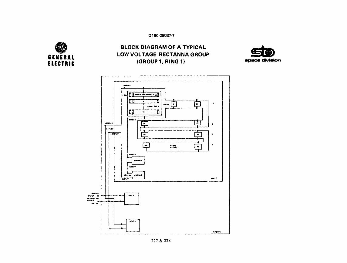
• GENERAL ELECTRIC
11'4.IV
•JOIJ' •Y
0180-25037-7
BLOCK DIAGRAM OF A TYPICAL LOW VOLTAGE RECTANNA GROUP
(GROUP 1, RING 1)
••1•v
OIOOI lfilUMO NO t f.J
, ..... t
0'110UI'. ~-t-·._-.~ OUlP\Jt 4
Ulfn I
IOllllll ._ ___ _....__. .......
... ,_ .. y
Lfllfff I
227 & 228
• ., •pee• dlvitllan
...........

• GENERAL ELECTRIC
TYPE 1 1·2 · · · ·27 2
lFOR RING 1) : 32
TYPE 6 ~·2 ... ·40
(FOR RING 61 : 32
0180-25037·7
LOW CURRENT RECTANNA WIRING LAYOUT FOR SEVEN DIFFERENT UNIT DESIGNS
1 0
I Q
2
i b
32 0 0
TYPE 2 1 •2 · · · ·32 2
(FOR RING 2) :
TYPE 4
32
1,2 .... 25 2
(FOR RING i) 32
2
Q ~" ·. "" -
RING 1
TYPE 3 1,2 .... 30 2
(FOR RING 31 : 32
TYPE 2 1,2 .... 32 2
(FOR RING 8) 32
229
27
0
TYPE 4 1•2 · · • .?.6 2
(FOR RING 4) : 32
TYPE 6 ~·2 . ' . ·40 !FOR RING 91
32
apace c.Hvlllian
TYPE 5 1,2 · · · ·31 2
{FOR R\NG 5) 32
TYPE 7 ~·2 ... ·35
(FOR RING 10) ~2

0180-25037-7
SUMMARY OF LOSSES AND TRANSMISSION LINE WEIGHTS
The table displays the loss and weight characteristics of the DC po~ar collection system of the rectenna. Using the previously described "low voltage" design the loss can be kept at 1.393% at the cost of 253490 metric tons of aluminum conductor. The bulk of the loss is in the panel lines and the bulk of the weight in the unit lines, thus the system can be improved by further optimization. Conductor weight can be reduced to 32424MT (to 12.8%) by allowing+ 27.2 kV within the rectenna. ("High volt$lge" design.) -
230

• GENERAL ELECTRIC
Ring Panel
1 7.40
2 9.41
3 8.44
4 4.03
5 5.03
6 4.92 I
7 2.30
8 1.44
9 1.46
10 l.80
'•6. 2 3
Total DC Power at Diode Output
Loss %
Total DC Power at Inverter Input
0180-25037-7
SUMMARY OF LOSSES AND TRANSMISSION LINE WEIGHTS
Loss MW Weight T
Group Group Unit Line Total Panel Unit Line
1.98 .12 ' 9.50 535 12991 406
3.54 .08 13.03 876 21299 333
2. 77 .25 11.46 101+2 12661 1187
1.59 .14 5.76 272 6832 320
J.02 .28 8.33 '•45 11181 524
2.48 .46 7.86 620 30491 2859
.90 .15 3.35 185 18591 1743
1.29 .16 2.89 llt6 201169 1279 . 1.03 .06 5.44 187 52357 1636
1.40 .18 3.38 30 48931 3059
20.02 1.88 66.13 4339 235803 13348
4891.4
l.3S3
4823.3
231
apace dlvilllan
Total
13932
Z2508
' 14890
7424
12150
33970
20519
21894
54180
52020
253490

D 180-25037· 7
LROUND POWER COLLECTION AND TRANSMISSION SYSTEM
The integration of SPS power into electric utility power system will depend largely on the local system characteristics. The work in this area included an assessment of using AC at differe~t voltage levels and/or using DC for long distance power transmission.
The failure characteristics and modes for the elements in the rectenna AC power collection system were developed and integrated into reliability profiles describing the availability of the various rectenna layouts studied.
The maintenance requirements both periodic and unscheduled were assessed and tabulated.
232

• GENERAL ELECTRIC
TASKS IN PHASE 1
0180-25037-7
GROUND POWER COLLECTION AND TRANSMISSION SYSTEM
• INTEGRATION OF SPS POWER INTO A TYPICAL ELECTRIC UTILITY POWER SYSTEM
• FAILURE MODE AND RELIABILITY ANALYSIS OF RECTENNA AC POWER COLLECTION SYSTEM
• MAINTENANCE REQUIREMENTS FOR THE AC POWER COLLECTION SYSTEM - SCHEDULED AND UNSCHEDULED
233

0180-25037-7
INTEGRATION OF SPS POWER INTO A TYPICAL ELECTRIC tn'ILTTY POWER SYSTEM
The critical parameters when considering what kind of transmission ·system and what voltage levels will be feasible for connecting SPS power plan'.s to the power grid is first, the distance between the SPS plant and the load cenLers served. The existing AC transmission system may be applicable for part of the power but stabilii:y and system reliability considerations may well indicate a mixed AC and J}C system.
Since thP SPS system is likely to be far more stable than a conventional power plant of the same rating the breakeven between AC and DC might well be different than in conventional systems. Due to the possibility of extreme reliability criteria being imposed on a SPS system, the conventiona~ transmission planning contingency criteria will also need review in site specific studies.
234

• GENERAL ELECTRIC
0180-25037-7
INTEGRATION OF SPS POWER INTO A TYPICAL ELECTRIC UTILITY POWER SYSTEM
CRITICAL PARAMETERS
• LOCATION OF LOAD CENTERS RELATIVE TO SPS RECTENNA LOCATION
• EXISTING POWER TRANSMISSION SYSTEM
-DISTANCE FROM SPS LOCATION
-STABILITY
• TRANSMISSION PLANNING CONTINGENCY CRITERIA
235

0180-25037-7
INTEGRATION OF SPS POWER INTO A TYPICAL ELECTRIC UTII.ITY POWER SYSTEM
Previous arrangements shown using a redundant set of transmission lines has been restudied and the arrangemeut shown in this figure using a total of six 500 kV circuits would be applicable if the SPS would serve one major and a couple of minor load areas. It is anticipated that any two of the 6 circuits could be r~moved from service without reduction of the rectenna output. The re111ainlng four circuits. together with the normal utility transmission interconnections should be capable of carrying the 5000 MW output required.
236

• GENERAL ELECTRIC
0180-25037· 7
INTEGRATION OF SPS POWER 11\ITO A TYPICAL ELECTRIC UTILITY POWER SYSTEM
CONSIDERATIONS FOR AC BULK POWER TRANSMISSION
500KV
TRANSMISSION REQUIREMENTS FOR UTILITY INTERPHASE

0180·25037·7
INTE<;HATION OF SI'S l'IMEH INTO A TYl'JCAI. ~:1.ECTl<JC UTILITY POWER SYSTEM
For conv1.:nt·ionnl ~t.merati(lr1 utatiom;, depending on the distance to the load c:enter, some ser!cs t·apacitor compf.msation of the AG lrnni;mll';sion lirt:s would normally ht~ 1Ji<pected when considering conling{•ncy lliu: loadinKS· Typical line lou<Jini<s vE1rsu.1.1 distance: and amount of scr1.es compensatl.on for AC trnnsmisi-don 11.nt:s is shown in this figure.
When consid,~r1.ng contingcnq1 loadings :1s discussed before with 2 lines aown and 4 lines carrying the fu 11 SOOO MW the line loadings would be 1. 2.S t 1mcff ttrn surge Impedance load t ng (Sil.). The s1..oe impe<l;rnce loadiil~ for various voltage levels are shuwn in the table and for 500 kV. the SH. would be about 1000 MW. From the curves it would appear that a reasonable tranamission distance with no series compcnsatinn for th:ls example would be about 200 mJles, which cuuld be increased to 350 or 400 miles with up to 70% Herles compensation.

• GENERAL ELECTRIC
J.0
2.0
TIMES S.I. L.
1.0
0180-25037·7
INTEGRATION OF SPS POWER INTO A TYPICAL ELECTRIC UTILITY POWER SYSTEM
CONSIDERATIONS FOR AC BULK POWER TRANSMISSION
• • Xe
..._ _ __,.I( r~
• NOTE: SERIES COMP[NSATION TYPICALLY APPLlf:O lf:YONO 1~0 • 2,0 MILES
AIPAHINTATSVI LINI IURGI
~~~~~~~~~~~-COMP IMPEDANCE LOAOINGI lllLJ -:;. 10%
THREE FOUR LINE VOLT COND\..'CTOA CONDUCTOR
kV MW MW
242 209 0% 382 418 I04
HO 1080 1180 IOO 2280 2480
0'--~~--~~--1--~~ ...... ~~--~--~--~~--o 200 400 600
MILES
TYPICAL ECONOMIC LINE LOADINGS
239

D 180-26037· 7
INTEGRATION OF SI'S POW EH 1 NTO /i. TYPICAi. ELEC:TR IC 1.:'I tJ,IfY POWER SYSTEM
When suhstnntial amounts of power urc to be Lransported for distanceti of 400 miltis or more, the 1·c,nsid1.·ration of a high-voltage DC (llVllC) as the transmission load iH often indicated. TI1e HVl>C system is id~11lly suited for lonK distance hulk power transport sin~e it does not suffer from stability effl!cts and can E'Vcn be used to :Improve the stability of the AC system to which it is connected.
There arc, however, <"ertain specific requirements to be met. At e11ch of ito terminals the DC transmission system absorbs reactive power which must be supplied by static capacitors, rotating m1:1d1ines, like synchronous condensers or from the ('onnected AC network. Reactive volt-amperes equal Lo approximately 60% of the transmitted acti.ve power are r<.?t111ired.
The current on the AC side of the t"!rminals contains substantial harmoni.c components which must be• rf:!nooved, generally by shunt-connected tuned circuits.
Lastly, the DC terminal must be connected to an active AC network having a short circui.t capacity (in vol c-amperes) t•qual to a minimum of two times the transmitted pow~r,
Wlrnn the requirements for filtering, reactive supply, and short circ11it ctJpacity are met. the llVllC ~ystc!m is a rel !able, efficient, and rt.?a!.IUy controlled power transmission medium.
240

• GENERAL ELECTRIC
0180·26037·7
INTEGRATION OF SPS POWER INTO A TYPICAL ELECTRIC UTILITY POWER SYSTEM
CONSIDERATIONS FOR DC BULK POWER TRANSMISSION
DC INDICATED FOR
• LONG TRANSMISSION DISTANCES > 400 MILES
• STABILITY PROBLEMS IN EXISTING AC SYSTEM
• RELIABILITY AND EASY CONTROLABILITY
DC REQUIREMENTS
• REACTIVE POWER SUPPLY ,... 60% OF ACTIVE POWER - STATIC CAPACITORS - SYNCHRONOUS CONDENSERS - CONNECTED AC NETWORK
• CONTROL OF HARMONICS BY FILTERS
• MUST BE CONNECTED TO AN ACTIVE AC NETWORK WITH SUFFICIENT SHORT CIRCUIT CAPACITY
241
.., llPllC8 clv191an

D 180·25037·7
INTEGRATION OF SPS POWER INTO A TYPICAL EI.ECTRIC UTILITY 'POWER SYSTEM
A typica 1 HVllC power transmission c ire ult is shown in this Hgure. The synch\ ;,nous condensers and AC filters are shown t•onnected to the AC switchyard. The OC terminal consi.sts of three phase bridge convert ors connel·ted in para) lel on the AC side and in series on the DC side. Although only two bridges are shown between ground and the UC conductor, it :1.s not uncommon for four such bridges to be applied when the DC voltage exceeds ± 400 kV.
1be DC system is balanced with respect to ground and is firmly held this way by fully rated gniund elect rodes. In norma 1 operation there is no current in these ground electrodes, but in an emergency if one conductor or its converters are lost, the other conductor and the ground circuit will continue to transmit hulf power. Such emergency use can usually be tolerated. 11\e transformers which couple the AC tiystem to the bridges are shown equipped with load tap changers (LTC) which insure that the converter op<:!rates at the proper voltage and firing angle regardless of normal smaller variations in the AC s;stem voltage.
242

• GENERAL ELECTRIC
0180-25037-7
INTEGRATION OF SPS POWER INTO A TYPICAL ELECTRIC UTILITY POWER SYSTEM apace dlvltllan
CONSIDERATION FOR DC BULK POWER TRANSMISSION
SYNCHRONOUS CONDENSERS IT REQUIRED
AC, CIRCUIT BREAKERS
AC .....-'m;,_~-. LINES
&..I"-..... TO ...._~ .. LOAD
ELEMENTS OF A HVDC TRAN~MISSION SYSTEM
243

0180·25037·7
FAILURE MODES AND EFFECTS ANALYSIS
The failure modes and their effects was analyzed for the power transmission system between the elevation flexible joint on the spacecraft to the utility interface on the ground, The summary presents some of the most important results.
244

0180-25037-7
• FAILURE MODES AND EFFECTS ANALYSIS SUMMARY GENERAL
apace divlalan ELECTRIC
•
•
•
•
•
• •
•
WITH CONVERTER REDU1..,DANCY THE SPACE ANTENNA CiC. SYSTEM HAS A MEAN AVAILABILITY OF APPROXIMATELY 99.5%.
THE PHASE CONTROL. SYSTEM MEAN AVAILABILITY IS 99%, THIS CAN BE IMPROVED IF THE FOURTH LAYER IS DUPLICATED, BUT THE COST PENAL TY IS VERY LARGE. ANOTHER POTENTIAL IMPROVEMENT IN AVAILABILITY {AND COST) MAY BE POSSIBLE BY OMITTING THE FOURTH LAYER AL TOGETHER.
THE MEAN AVAILABILITY OF THE KLYSTRON AND ITS DRIVER IS 97.45% WITH 20 YEAR LIFETIME TUBE AND HALF YEARLY MAINTENANCE. POWER LOSS CAN BE CUT BY NEARLY A FACTOR OF TWO IF QUARTER YEARLY MAINTENANCE IS IMPLEMENTED.
COMBINED EFFECTS OF RANDOM ERRORS IN THE APERTURE DISTRIBUTION AND LOSSES IN THE PROPAGATION MEDIA ARE COMPARABLE TO THAT OF THE KLYSTRONS.
MEAN AVAILABILITY ASSOCIATED WITH DIODE FAILURES IS APPROXIMATELY 99.45%, ASSUMING NO DIODE OR PANEL RELATED MAINTENANCE.
THE RESlA... TANT DC POWER COLLECTION SYSTEM CAN HAVE A MEAN AVAILABILITY OF 98.4%.
THE RE SUL TANT AC POWER COLLECTION SYSTEM MEAN AVAILABILITY IS 99. 7%,
RESULTANT SYSTEM EQUIPMENT AVAILABILITY BETWEEN ELEVATION FLEXIBLE JOINTS AND UTILITY GRID IS APPROXIMATELY 90%, POWER AVAILABILITY IS HIGHER THAN 86%.
NUMBER OF POTENTIAL AREAS WERE DETECTED WHERE AVAILABILITY IMPROVEMENT CAN BE IMPLEMENTED IN COST EFFECTIVE MANNER.
245

0180-25037-7
AVAILABILITY VS. PROBABILITY FOR SPACE ANTENNA D-C DISTRIBUTION SYSTEM FROM OUTPUT OF FLEXIBLE JOINT TO KLYSTRON INPUT
The figure shows the availability of the spacecraft DC curve is shown for .075 failure/.5 year failure rate DC to The available power for this casf: falls below 99. 5% of its or otherwise it stays above this value in 66% of the time. (rms) value of the available DC power.
246
power distribution DC converters in a maximum in no more This value may be
system. The resultant redundant configuration. than 2980.4 Hrs./year taken as the average

0180-25037-7
• GENERAL AVAILABILITY VS. PROBABILITY FOR SPACE ANTENNA
0-C DISTRIBUTION SYSTEM FROM OUTPUT OF FLEXIBLE JOINT TO KLYSTRON INPUT apace divieian ELECTRIC
~ > !:: _, iii ct _, ct > ct ... 0 I-z w (.) r:r: w Q.
A% HOURS PER YEAR 878.8 438.3
100
99
98
97
96
95
94
93
92
91
7898 6138 2981)4 87.7 8.77 .88
··~ ---........r--... ,..sueA1RRAY
· ·-- ---lf------="""'-ok:::~---+---+---+-.::3oo...,.....,=f-~-r...:.=L~ES
......... , '""""- I ~---+---.J.-----+--""'oo"'.-----+------+----t-----1~N::---J-----,.-t-SECTOR LINES ··~ I AND DC/DC
~........ CONVERTEk
"-... ''""" P•.075f t-----+---.J.------+----l--""r----11-------+--+---+--3'.....--'l'oo...--~YEAR
"' "·, ~ N•228
"'- RESULTANT DC__............ " - DISTRIBUTION '-
SYSTEM "-
' ' I SECTOR LINES -'-.. AND DC/DC .,__---+---+------+---~-----lf----+--+--..-+-t'--CONVERTER -
"' / P• .188 f ~-+----+-----t-------+-----+-----+---+---------t .S'YEAR_
""- N •228
" 1-----1---·- _____ ,. _____ --- ---+-------- ------ ----1---~--~
" " 1----+------f----·--· -------------------·-+-------+--+---+--------
-----+----+--------- ----·--- _,, _____ ------+--t-----11-----T----t
0.1 10 ~., fi6
PERCENT OF PRCJBABILITY Iii)
247 & 248
90 99 999 ir" 99.!f9

• GENERAL ELECTRIC
99
98
~ 17 > .... :i
~ 98 _, C(
~ ~ 15 .... z w u a: ~ ...
13
92
91
..___.
0.1
0180-25037-7
AVAILABILITY VS. PROBABILITY OF A STRING OF RECTENNA DIODES CONTAINING Nos= 43
PARALLEL DIODES
HOURS PER VEAR 7898 6138 21804 876.6 438.3 87.7
~ f--·
~
--·- ~--~----- -~ \.
N Ds '3, ! • .02 • ,, FAILURE • , • 30 YEAJI "\. T 30VEAR
~ ----\.
apace dvllllon
8.77 .88
-
\ -- .
\ \ ·-
\ \ \
;
10 ='3 66 90 99 -" 99.9 99.99 p
PERCENT Of PROBABILITY (Pl
249

0180-25037-7
AVAILABILITY ~rs. PROBABILITY OF THE SPACE ANTENNA PHASE CONTROL SYSTEM FROM INPUT OF PILOT RECEIVE ANTENNA TO KLYSTRON INPUT
The figure shows the availabilitf of the spacecraft phase distribution system. The average value is 99%.
250

• GENERAL ELECTRIC
Jo
0180-26037-7
AVAILABILITY VS. PROBABILITY OF THE SPACE ANTENNA PHASE CONTROL SYSTEM FROM INPUT OF
PILOT RECEIVE ANTENNA TO KLYSTRON INPUT
HOURI PER VEAR @sw, OUTPUT TO ~
1810 OUTPUT
7898 1139 2980.4 879.9 438.3 17. 7 •. 77 .•
,~~===r====~==:.:~~:i..f:-=-:=.:t.;~~~-~· :r:::~-=-r-:i~==~·s;;;i:~\J ............. """"" ---- ...__ ©INPUT TO~
~ ~ sw,.ouTPUT~
-------- --- ------ -~;, "--®~.:::~ --.... """""'" ''- """""- ()emn OUTPUT TO
91 t-----+---
----·--·-··---··· -·- -·--- -----~ ~ ' KLYSTRON INPUT-
~ 97 t----+-----+---- _,I----+-----.. ~~!~~ ~~~~~OL \,., ~ V/ SYSTEM '\.. "\...
~ -- ------··- .. - . ·-- . -- ... .... . . .... -·- - ·-·- -- --~-- --·----4·-----t
i- \ " ~ ------ ---- _.,_________ --- ... ------·---- - . ··-- ------··-- ----- ----- ------ .......... -~ ~ ff~--'---__..----+-----+---~ ,. \ ~ --- . --- ------- --------------·-- . - •.. .. --- ·-·--·-----···--· ------- -- . ---- ·-----~~ ---·-~ ' : Mt-----1-------1----"'----'---·~-'--------ii----+----~~..__--4
\ ··--···---,-93t----t----1-----~--4----4--~--1--+---4----'-~~·-1
··-----~-\
.. - ... ,"
----~---··
92t-·--+----+---·--i~--.__---+---+---1----1--~-i----M' I
----·- ---91..._--:-:A-::-----!~---~--~---~--~~-L..--~---'------J -~
0.1 10 30 86 90 99 99.9 99.99 p
PERCENT OF PHOBABILITV (IS')
251

0180·25037·7
AVAlLABlLI1'Y VS. PROBABILITY OF KLYSTRONS BASED ON AVAILABILITY OF A GROUJ· OF NG • 380
The f1gurc shows the availability of klystrons and th~ir associated drives. Twenty year lifetime is assumed foe this assembly and refurbishment is provided half yearly. The average value of availability is 97.45%. On the average 2544.6 klystrons l1ave to be replaced biyearly out of the 101784 operational unite.
252

0180·26037·7
• GENERAL AVAILABILITY VS. PROBABILITY OF KLYSTRONS BASED ON AVAILABILITY OF A GROUP OF NG• 380 •• •pmc• dlvllllan ELECTRIC
HOURS PEA VEAR
7111 11H 21104 171.1411.3 17.7 1.77 •• .. ' .. ~ .. --... --~~-
·......___. ----· ----------··-... ----.. ~K..-- .. ·------· --·----- -···-----l-.. --~ 97 ____ .. ______ ·-----·- ----·· ... ····-·-··--· ......... - -·-·" ·--~~·-···4----~---- --·-~ I """~ l·L-~~~~~~~-i-~--1--~---+-~~+---.P....ir:--t-~~-r----; ~ --------t-----·-··-·-------- ...... -................. ·-· ........ --~K_ .. ___ --! " ~ z ------'-----+--·---1f-----t----·~~---·----.&.-~---&.---~,---f
~ "" ~M ~ ~---'---~-------J--·--·· .. ·- -··--... -- ...___ __ ..,, ... ,_ l---·-· -~----t----1
-----"-----'---···-- ------· --·-- -·----- - -·---+-----+----!
1----4----4-- ,. _____ ... -· .. ----~·~····· ... ·------·- ·-·---·-.......... ,, .. _ ·-"' •··----1----·-· ~--11 L----OL.,----....... ------~,~o--·--~l~1------~M::----~~.o::--..J.-----:,~,----.,~ •. 8.--~ ... H,%
PERCENT OF PH08A8tLITV 1,1
253

0180·26037·7
AVAii.ABILITY VS, PROBABJJ,ITY OF POWER OU'fPUT FROM !DEAi. SPACE ANTENNA DUE TO RANDOM
APERTURE ERRORS AND PROPAGATION CONDITIONS
The fi~ure shows the availability of effective antenna 1ain as it ia influ~nced by random variables. Effects of aperture phase errors, aperture amplitude errors, attenuation in the media attd effects cauaed by Faraday Totation.
254

• GENERAL ELECTRIC
0180·25037·7
AVAILABILITY vs. PROBABILl'rv OF POWER OUTPUT FROM IDEAL SPACE ANTENNA DUE TO RANDOM APERTURE ERRORS AND PROPAGATION CONDITIONS
HOURS PER VF.AR 1198 1131 2!1110.4 878.I '311.3 fH. 7 8.77 ...
---r---. ~-·--· ···-·-
'----· .............. FARADAY _.,. """-- I --.""-.._ RCTATION
........ ~ · ;A~~~~~~~ll~N L .. ~ _ 9Br---t-~--t-----1'----~t-----t~-~~~~-+----+---+-~~ ~ ....__ _______ .._ _______ ,_, ...... .. --- ---· ~~l, .......... -- ..
; v =~-=----4-~ _-_-__ -_ *---~-----....... -... -... _--+_ ..... - .• - .... -.. ,_-____ -'_ -___ -_-_ .. , .-. --t= .~~ ~ ---~ 96 t---4----+--
~ ....._--+----- ...--·----··" ..... ··---------- 1.-.. ------+----+- "'' "-~ 95 ·-----·-··· -·- ~ ' SPS
a. ··+--+---+---~,-~i...1"- RANDOM --- --·------·---- .._ _____ ............ ·-··· ----.. ··--- ........... -.. ·--·-·· .. ·-···---~\- =~~R
. . . . ............ -----.. ......... .......... ----- ................................. ---- .. \ '\ ', ' 931----+----+----4----l~---+--~-+--+--~-'--~-'---l..J
SPS _...\
-·--1---·--·-·-- ..
----- ........... __ , .......... ---- .... ·---~----:~~~M ' 92t----+---+----~----1~---+----+--1---~ERROR -+----41
..___ - ................ ---·-----·----- ...... .. ( fl'' 1 • .06°1
~~--·----··--···--- ~- ··---- --91'----7.-:--~-----:~---::'::---~~-~~--1---L~~-1.~---' 0. 1 10 30 88 90 91 99.9
..... 99.99
PERCENT OF PROBABILITY 11'1
255

0180-25037·7
AVAILABILITY VS. PROBABILITY OF A TYPICAL RECTENNA PANEL CONTAINING N • 1849 DIODES
The mean value of availability of a typ1.cal rectenna panel is 98.85% with state-of-the-art failure rates (.04 x io-6 failure/hours). A factor of 2 improvement in failure rates increases the mean availability to 99,45% at the end of the 30 year lifetime. The improved value is assumed for system availability calculations. The dipole pan~ls will be refurbished only after 30 years.
256

• GENERAL ELECTRIC
0180·25037· 7
AVAILABILITY VS. PROBABILITY OF A TYPICAL RECTENNA PANEL CONTAINING N = 1849 DIODES
A'K. HOURS PER VEAR 8138 29804 878.8 438.3 17.7
100.--~~-------.~--~--.....---~""T,.
.8
.6
.4
.2
2
.8
6
I !
apace division
1.77 ••
4,__ __ __._ ____ --J--~--~~--- -~~~--__. __________ .__ ____ ...._ ____ .._ __ __, -'Kt O. 1 10 .!O 66 90 99 99 9 99 99 p
PERCENT OF PROBABILITY ~Pl
257

0180-25037·7
AVAILABILITY VS. PROBABILITY OF A TYPICAL RECTENNA STRING OF PANELS CONTAINING Np5 • 872 PANELS
The mean availability of a typical rectenna panel string (unit) is 99.38% on the account of DC bus line failures if the mean time to repair is r • 876 Hrs. Lines are continuously ~.aintained.
258

• GENERAL ELECTRIC
. 8
.8
.4
.2
0180-25037-7
AVAILABILITY VS. PROBABILITY OF A TYPICAL RECTENNA STRING OF PANELS CONTAINING
Nps = 872 PANELS
178.8 438.J 17.7
• ., •pace clv191an
1.77 ••
•1--~-+~~--11--~~~-+-~~~r-~~-t-~~~ ....... ~~~-+-~~-+~~~
N,..., N • ...c • 872, N • 87240,
,,. 10 Pl
_! • 8.3 11 trl FAILURES T VEAR
.4
.2
.8
.8
PERCENT OF PR08ABILITV IPI
259

0180-25037. 7
AVAILABILITY VS. PROBABII.ITY OF UNIT TO GROUP CENTER LINES FOR NG • 784
The mean availability of rectenna unit to group center connecting line is 99.65% if the mean time to repair is r = 876 Hrs. Lines are continuously maintained.
260

• GENERAL ELECTRIC
.8
.6
. 4
.2
-99 ~
~ .8 :::; ~ .6 _, ~ .4 <I:
~ .2 ..... ~ 98 u er: ~ .8
. 6
. 4
. 2
97
.8
6
. .:
..
..
..
..
..
...
...
..
..
..
..
..
0.1
0180-25037·7
AVAILABILITY VS. PROBABILITY OF UNIT TO GROUP CENTER LINES FOR No= 784
7898 1136 2980• 8768 438 3 87 7
--............. ~ I
!'---.........._ ~
'-..... NG •784, ~ .,..- .0315
FAILURE , r • 878 HRS, P • .003115 VEAR
10 30 66 90 99 PERCENT OF PROBABILITY IPI
261
§§) apace divilllan
877 ..
~~
;" 99.9 99.99

D 180-25037-7
AVAILABILITY VS. PROBABILITY OF RECTENNA D-C POWER COLLECTION SYSTEM FOR VARIOUS FAILURE CHARACTERISTICS COMBINATIONS
The mean availability of the rectenna resultant DC power 1.:ollection system is 98.4% with .02 x 10-6
failure/Hrs. diodes and 876 Hrs. mean time for repair allowance on the DC lines. For the predicted failure rates a crew of 29 is necessary to maintain the DC power collection system.
262

• GENERAL ELECTRIC
A"fe
100
99
- 98 !!. > t: -' iii 97 <( -' <i ~ ~ 96 .... 2 w u IC ~ 95
M
93
92
91 0.1
0180-25037-7
AVAILABILITY VS. PROBABILITY OF RECTENNA D-C POWER COLLECTION SYSTEM FOR VARIOUS FAILURE
CHARACTERISTICS COMBINATIONS
HOURS PER YEAR
7898 6136 2980.4 876.6 438.3 87.7
r--.__
~-- r--..__ -................ '~ ~ ....... ~ '.........,; -- !"-
~~ ~ ~ ~ t- ....... ~
i'...._ ,_ """ ... ~-..~ -.............. .....
"' '"' .. .............. _ ~
I'., ' r-.... .....
space dlvilllan
8.77 .18
.......
' ·--· -, "'' ........ ~ r.11tl11r" ..... -hi lure "°411• Ch•r•t 1 ,,, '"'Jes C.u• I . e-~'-~~!.!) .OJ • 10-• i JO '¥Par
Diode r (••"ti .. 0,.•11 tlrc111t to r•·..-11)
)0 .....
PJ • . ' . S2~\16
---___ ... _._ .. ____ ----·--i ('"''"'") J•>·•t•.ar
.on:1
,.,.n•l 5trinJ r (at.•an tl .. Klt. 111<1. Short t•r~ult to rrpah)
•' .o -'---(' .-; ..... ) 1 JrJ ,, . .-, !l•l\<I•
1'nl\ lh1r r tM~n ti• Iii'- hr>1. .. lwrl Lu .... 1t tD '"pair)
I . HS _L__
10
....__!.!!.!_l__. ~·-J _ __f.!!!-.L_
.04 • rn·6 02 • 10-• .04 • 1o·A
)0 , .. ., JO , ••• JO,..., 1.rr.i92 .SHH I .0'.191 --..._ _______
,00!1 ,llfl'I .rl'l.'I
141fi hr111. 17\2 ""'· 11-iz hu•.
·•}_ 1.16 l.16
.0010·, ,ll01fl'1 ,IMllll'•
)'f.]ft "'"· lllh 111 ... K1f:I ht~
. llS . JU .1U . ! :
PERCENT OF PROBABILITY (Pl
263
,,
{
-90 99
""'-.', ~ ......... ......
99.9
.......... :3) -, ..... ©
_,, 99.99 p

0180-25037-7
RECTENNA Ar •OWER COLLECTION SYSTEM
The diagram shows an idealized AC power collection network, developed during the Part III study, which can be used for availability calculations.
264

• GENERAL ELECTRIC
20 8LOCKS
20 BLOCKS
!IOOO TOTAL
0180-25037·7
RECTENNA AC POWER COLLECTION SYSTEM
20MW
DC SWITCHOl:AR
20MW
2flO TOTAL
40MW
CONVIRTIR ITATION
.. -{ BLOCK I
121 TO"Fl•L
ZOO MW
SYNCH. CONOINSIP.
TRANIF. PIL TIRI
ITC.
265
I \I I T c H
., A R 0
TRANSi'.
200MW 8LOCICI
l!ll TOTAL
1000MW
I w I T c H
v A R 0
TRANSi'.
1000MW 8LOCICI
• TOTAL
IDOOMW
' w I T c H
y A R
"
' TOTl\l
TRANllMIUION LINH 40,.
CAN CARRY 1000 MW
...

0180·25037·7
AVAii.ABILITY VS. PROBABILITY OF OVERALL RECTl•:NNA AC POWER COLJ.ECTtoN SYSTr.s ..
Mean availability of the AC power collection system i" 99.7%, limited by the 20 MW stations.

• GENERAL ELECTRIC
0180-20037· 7
AVAILABILITY VS. PROBABILITY OF OVERALL RECTENNA
AC POWER COLLECTION SYSTEM
HOURI PIA VIAA 7181 ,,31 21110.4 171.1 4:11U 17. 7 I. 77 .•
100 -............."""""--- ~.._ ......_.._ \ i,..-1Mw
- -·· ---·---·- •... -· ~~"-- ~. ~~
""'·~ ~ 200Mw .. --- ---------- --'"--···--··-·· ·------- ·~·· .... ~< ~ 19.....__
·-·
~ 1 40Mw
~. " t----+----+----------- ---------·- ·---- ·----__.·-~·-·- -·- ~ i-1 I\ 20Mw $"~----+----+-------ii------~~----"
~ -----·!----··---------- --------- L.... --- .-.-- "!c~~~;:~1 ____ \4-----f-.., ~ ' ! 16 •. 'DOO Mw
s ---- ~- -·-··-·-- -·--·-· .. -·---f..--·--1----·l--1\_,~ ..... ~" - ·, I --~·- ·-+--------·---1---·--· ·---·-· ... ---'"---·--·-~- \ f Mt-----t-----t-------il------1------4----J---1-----~---"--''-I
·-------- -----····· '-·-·-········- ---- --- ----~--i "r----r-----t-----il------1-------4------4---'----~-----J.----lJ; -------·- ................... ~ ......... .,-~- -~ ...... -·"--- ·---~···-·· .... ··-.. - i..,__,._ .. ___ ·-................... _..__ .. _ --.. --+----U
... . ····-·- -· -·--·-+-----1
11-----;t;----t--------::-----::=------:1::------~-J----~-----l.--__J u.1 10 30 11 to 11 "·* n.tt'
PERCENT 011 PROIAllLITV CPI
267

0180-25037·7
FAf.LURI~ MOlrn AND lrnLIAIHl.TTY ANALYSlS
The calculation of 11 rcUahiUty profil<.! of the AC poWE!r collection Hyat:em was performed for :tll thrcu lc.iyout options. The reliabili.ty profil1.1 calculnled wll.J show tl11.! power output from 11 625 H4 rec:tenna sector ns a function of the percent of timl! inn year. The block dfof~rnm 1n this figurt~ showH the fluw of the probab1Uty c:ulculutJons. The fallurt.: dwruct~rlstics are 1ndic11tcd on the figure.
Mathematically th(;• calculations are pcrformC!d by wdng the bin()rnJnl probabHi.Ly function for each of the groups in each design to whkh it applitHI am! then combining t:1e prohahiUties of com\)onent outag1.H> and tile associated powl!r 1ost to develop the data needed to draw the reliability profiles. The assumptiuns used are:
1. The cxpo$ure period is 8760 hours
2. Thi:! swJ.tchyards and the synchronous condcn!lcrs are dctd~ncd not to contribute to power outagE.>t;,

• GENERAL ELECTRIC
UNIT
>.10 f I 0
(::.~)
0180-26037·7
FAILURE MODE AND RELIABILITY ANAL VSIS
DC SWITCH GEA"
). I .2 , I I
DC IUS
CONNECT.
DC INVE .. TU -- DC/AC INVElllTElll •AKER tNYPTllll TlllAN9'0Mmt
). •.00013/IREAKElll >.I .2 r •IS r• I
~•H f I IQ
)_I .00J f I 7&
AC SECTOR ,------,
---1 CUtCUIT -- STEP•UP SECTOR 19/230 AC SW ITCH I STIP·UP CAIL.I
8"!AKER TRANIFOAMIR
~ •.0171 , • 3.1
~•.013 r I 72
YAlllD TltANW'ORMDt --- &.;.. _____ :a
BLOCK DIAGRAM FOR RECTENNA SECTOR RELIABILITY CALCULATIONS
269

0180-26037-7
FAILURE MODE AND RELIABILITY ANALYSIS
The reliability >rofil~ for the 625 MW sector considering the elements in the AC power colle~tion system is shown in this curve.
'fl·e reliability profile is shown in the figure. The reliability of the rectenna AC power collection system is very high compared to current utility generating equipment, bot:h in the baseline design as well as the other designs studied, and the choice of any of these three desiKns will not depend on these reliability considerations,
270

• GENERAL ELECTRIC
O/o
100
99
98
97
96
0180-25037·7
FAILURE MOOE ANO RELIABILITY ANALYSIS
MW
625
620
615
6 10
605
600
~ I 20 40
RELIABILITY PROFILE FOR A 62& MW ;ECTOR IN THE LOW VOLTAGE BASELINE RECTANNA
DESIGN
60 80 90 99 99.9 99.99 % OF TIME
271
..

0180-25037-7
SUMMARY OF EQUIPMENT MID POv/ER AVAI!.ABILITY CALCULATIONS
The table swrunarizes the equipment availability and AC power to utility grid availability on the account of the analyzed part of the SPS system. Input interface is at the output of a flexible DC cable on space antenna, output interface is at input to utility grid. All effects which cause statistical variation of availability (failures, e~·rors, propagation) are included. Some of the ma,jor &18umptions:
• Space antenna DC to DC converter is redundant.
• Phase control uses four layer tree, down to klystron level, only first and sec1;:-d layers are redundant.
• Nonredundant, 20 year lifetime klystrons are used. (This is a factor of ten better than state-of-the-art).
•
• •
•
• •
Random phase and amplitude errors of space antenna are the same as calculated in Part III Study.
Elevation angle toward satellite is 55° •
Diode failure rate is .02 per million hrs. Diode is ,1ot rt)furbished for 30 years. (Failure rate is a factor of two better than state-ofthe-nrt).
Critical components in AC power colJection sy:;tern are redundant, rest are covered by on-site spares.
:::pace ant<.inn~. is refurbished with in Bh hrs bi yea.Ply peri ·1 s •
ifo power :cecovery is assumed \o1hcn a fa i Jure occurs ln space antenna tl.Der·ture :>egrnent related to items G) , @ or (ti in tablt:.
Not,r, tho. t 1·ri th po 1.1:::r recovery method:; Lhc 1!2.'."cr av<iilr.b:i1 !~V ( lh .P-)',1, 1aean value) c<:r; be im~iroved to tt,e cnu:iprnent o.v.:d1abil~ty (90.12;; me<m value). - _ _,

• GENERAL ELECTRIC
A.
B.
c.
0180-25037-7
SUMMA~Y OF EQUIPMENT AND POWER AVAILABILITY CALCULATIONS
--
space divlelon
p% 10 66 80 90 99 99.9 99.99
Hrs/Yl.'11r 78A9 2980 1753.2 876.6 fl7,66 8.766 .8766
Spac~Q!l!! 97.75 93,20 91.56 89.59 811 .12 78.62 71.28 -- ---··
l DC Distribution 100,00 99.50 99.22 98.95 98,00 97.00 95.95
2 Phase Control 99. 811 98,92 98.114 97.83 96.10 94.40 91.30
3 Klystron 98.90 97.50 97.02 96.55 95.48 94,58 93.60
4 Random Phase 99.40 98.SO 98.20 9 7. 82 96. 80 95.75 94,80
5 Random Amp. 99.60 98.60 98,110 98.00 96.65 94,90 91.70
ProEa&at ion 99,05 <.18, 511 98.28 97,8/i 96.24 94,17 91. 77 -- ·-· - -------···---·-----------
6 Attenuation 99.05 98.62 98,110 98.10 96.90 95.20 93.15
7 Faraday Rotation 100.00 99.92 99,98 99. 74 99,32 98.92 98.52
Rrctenna 98.38 98,13 97 ,61 97.03 95.06 92.96 87.65
8 DC power Collec- 99,38 98,115 98.15 97. 81 9 7 .oo 96. 38 95.RO ti on
9 AC Power Collec- 100.00 99.68 99.45 99.20 98.00 96,45 91,50 ti on
Total Power Trans-miss i.on Sy!< t e1n 96.22 90,12 87.78 811,99 76.% 68.88 57.33 Equipment Availahi-11.LY l'ow .. r Availali_!.!.!.U at l'oWL!r Gr iJ lntrrfacc Relative 95.00 85,85 83.19 79,113 69.20 59.65 47.()J to Equipment \Hthuut Jo'a1Jun•
- ---4·-~----·
273

0180·25037·7
AVAILABILITY VS. PROBABILITY OF OVERALL SPS POWER TRANSMISSION SYSTEM FROM OUTPUT OF FLEXIBLE JOINT ON SPACE ANTENNA TO POWER GRID INTERFACE
The chart shows the variation of equipment availability in the overall SPS power transfer system. If power recovery methods are used in the space antenna, then the outp~t power at the power grid interface is determined by the equipment availability. Without power recovery (redirecting the available DC power for DC to RF conversion to the still available part of the space antenna r~~~ating components) the available power at the utility interface is lower because a lost radiating component in the space antenna represents loss of power as well as loss of antenna area.
The mean avdilability for the two cases is approximately 90% and 86% respectively.
274

• GENERAL ELECTRIC
100
90
70
65
60
55
0180-25037·7
AVAILABILITY VS. PROBABILITY OF OVERALL SPS POWER TRANSMISSION SYSTEM FROM OUTPUT OF FLEXIBLE JOINT ON SPACE ANTENNA TO POWER
GRID INTERFACE
HOURS PER YEAR
7898 8136 2980 4 8788 436.3 87 7
-- -·· ~ ~
~-... '-,.., ~ "'" AVAILABLE POW~ '" "'" AT POWER GRID
' ~ INTERFACE
apace dlvltalan
8.77 .88
I "-. ~UIPMENT AVAILABILITY-
""~ "------ r--
"!\.. ' __ , __ " '\.
' '\.
' ' " .. ·- --·-- -----~--- --
'\ \ '\ \ ·--·--- --·~--·- ---------- ··- .. -~
-- --~-·-· ·------~ "---·-------- -- --~··- . -- ~---~-
0. 1 rn JO 66 90
PERCENT OF PROBABILITY IPI
275
\ \ , -·--- ·--·-, _ _\
99 -%
99.9 99.99 p

0180-25037·"'
AVAILABILITY OF EFFICIENCY AND POWER INTO POWER GRID
Table shows the worst case efficiency and power into utility grid as a statistical variable. usin2 results of the availability analysis. It diode efficiency is improved by 5% and power recovery methods are successful and spacecraft then the figures shown in tha table must be multiplied by 1.1.

• GENERAL ELECTRIC
-% p
Hrs/Year
0180-25037-7
AVAILABILITY OF EFFICIENCY AND POWER
IN ro POWER GRID
10 66 80 90 99
7889 2980 1753.2 876.6 87.66
apace diviaian
99.9 99.99
8.766 .8766 -----·------·- . ------------·-· --
Availabl~ Efficiency 63.33 57.23 55.46 52.29 46.13 39. 76 31.34 %
Availabl~ Power 4513. 3 4078.6 3952. 3 3773.6 3287 .6 2833.9 2231.4 MW
277

D 180-25037-7
EFfECr OF DEVIATIOiJ FR<J.1 BASELINE SPS ON RELATIVE OUTPUT POWER
This table shows the impact of various output power increasing options on output power and cost.
278

• GENERAL ELECTRIC
D 180·2503'1· 7 EFFECT OF DEVIATION FROM BASELINE SPS
ON A ELA TIV E OUTPUT POWER
A n B/A Option % Jncrcase of % I ncrl'asl~ of
Output Powrr Syc;tE>m Cost
A. Increase 4 and ~ bv 1.068 for 23 mw/cm max. 6.8 3.88 1. "15 Receiv~d Power DP.snity
-B Increase 4 and 3 by 1.1
Reduce 2 by 1.1 10.0 s. 71 l. 75 Increase 1 by 1.1
-c. Increase 1 by 1.1211
for 96. 77% beam 1.5 l. 73 .87 efficiency
D, Imple1nent klystron Maintenance in Every 2.5 1.58 1.58 3 Months
E. Hake LHt I.ayer of Phase Control .4 3.0 .lJ System Fully Redundant:
F. Refurbish Rectenna Panel Aaasembly After .58 3,57 .16 H Years
G. Reducl' r to 438 Hours
~ on Panel St rinr, .37 .35 1.06 Maintenance
---- --All the above options 81"1'
hnplf'mented. 23.88 2(1,50 .901
Avernr,r l'ower Ou I' put (5052 HW) ·----·-·--- ---- ---·-
Only Cost Effective Opt form A, B and I> 111"1! Imp lt•mr•n l l•cl 20. 1,;~ 11. 50 1. 77
/\vvraf',(' !'OI<."(' r Ou I p11 l (11?ll.l1 ~:w)
·-- ·- .... - ---- - -- ,. - ··-·-·····-·- '" . ··"-"" -·· .. --· - - "" -··- --- - ..... ----··--·- -··---- ----·-- ··-· ---279
•pec:e dlvillian

0180·25037·7
AVAILABl.E SPS POWI-:R TO UTILITY GRID
The figure shows the statistical variation of the available power of the utility in:erf•ce if power recovery 1~ not used. Impxoved diodes and power recovery mathods cMn improve the pred{cted values by about 9X. Chart considers all random failures and scheduled maintenance of 84 Hra./half year, however, it neglects ·~clipse and start up/shut down caused powel' output loases.
280
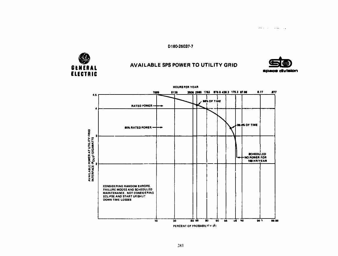
0180·26037·7
• GENERAL ELECTRIC
AVAILABLE SPS POWER TO UTILITY GRID •P8Dlt clvlmlon
HOURI PEA YEAR
11n 1131 3IOI 2tl0 1713 1711 4313 1713 1711 177 177 4.6
•
--.......... ~
I I i-.,k..._ll"'OllTIMll
RATED POWER-~
~ ~
\ 80% FIATED POWIFI- i-i.11.ftOflTIMI
'
ICHIDULID ·- ._NO POWER FOR 111 HFllVEAFI -
CONSIDEFllNG RANDOM EHROFIS, FAILURE MODU AND SCHEDULED MAINTENANCE. NOT CONSIDERING ECLIPSE AND START UP/SHUT DOWN TIME LOSSES
. -· 10 30 eo se 10 eo K t11 If& 91.99
PERCENT OF PROBABILtTV IP)
~81

0180·25037·7
The maintenance taske fer the SPS power t ransmisoion system were studi.ed and preliminary manpower requirements were established both for the apace and ground operation. The summary shows the man~ower needs.

• GENERAL ELECTRIC
0180·26037·7
MA I NTENANCE REQUIREMENTS
SUMMARY
• SPACE ANTENNA MAINTENANCE HOURS FOR 2 MAN CREWS. PER BIYEARLY CYCl..ES
•
•
DC DISTRIBUTION
RF REFERENCE PHA~F. DISTRIBUTION
KLYSTRONS
TOTAL CREW HOURS PER REPAIR CYCLE
TOTAL MAN HOURS PER REPAIR CYCLE
TOT AL MAN HOURS PER YEAR
RECTENNA OC PER YEAR
RECTENNA ~ . .;PER YEAR
281.2
680.5 2544
3506.3
7012. 7
14025.4
5762.5
69457
• THE MANPOWER REQUIREMENT IS EQUIVALENT TO APPROXIMATELY SEVEN MAN YEARS PER YEAR IN SPACE (ON THE AVERAGE) AND 64 MAN YEARS PER YEAR ON THE GROUND FOR 5 GW SPS SYSTEM,
283

0180-26037·7
NUMBER OF FAILURES AND ASSOCIATED MAINTENANCE TIME REQUIREMENTS IN THE SPACE ANTENNA POWJ!.R TRANSMISSION S'.'STEM
Table summarizes number of failures in space antenna power transmis~ion system within half year period and associated total repair horns requirement. Klystron maintenance represents 72.6% of total time.
284

• GENERAL ELEtiTRIC
l
0180·25037·7
NUMBER OF FAILURES AND ASSOCIATED MAINTENANCE TIME REQUIREMENTS IN THE SPACE ANTENNA POWER
TRANSMISSION SYSTEM 11pw ct1vlllian
f lira. Tot.al .S year ii'apair Repo.ir
Item N F .. p m Ti.mo
DC Convertor .075 456 34.2 4 136.8
DC Vector Line .00594 228 1.35 12 16.2
Subarray Line .000315 101784 32.06 4 128.2 . SW1 Output .01859 60 l.11 8 8.9
2nd n19 Output .006048 380 2.29 6 13.8
Hmm Output .005246 7220 37.87 2 75.7
ltlystron Input .007626 101784 776.2 .75 582.l
Klystron and Drive .025 101784 254/t. 6 1 2544.6
r-Total 3429.68 3506.3
-Man hours for two man team 7012.7
285

0180·25037·7
NUMBER OF FAILURES ANO ASSOCIATED MAINTENANCE TIME REQUIREMENTS IN THE REC'l'ENNA DC POWER COLLP.CTION SYSTEM
Table summarizes number of failures in rectenna DC power collection £iystem within 1/10 year maintenance period and the associated repair time requirements. Approximately 29 man can maintain this part of the system.

D 180-..:5037· 7
• GENERAL ELECTRIC
NUMBER OF FAILURES AND ASSOCIATS:D MAINTENANCE TIME REQUIREMENTS IN THE RECTENNA DC POWER apace ct1v1111an
COLLECTION SYSTEM
f !!!:!._ Tot. Repair Man Hours -.1 year Rapair Hrs. Per Main· p N F m . tenanr.:e Cycle
Panel String .0063 87240 549.6 5 (2 man) 2748 5496.l
Unit to Group .00315 784 2.47 18 ( 6 rrutn) 44.4 266.4
Center Lines
Total 5762.S
287

0180-25037·7
FAILURE r;ooE AND RELIABILITY ANALYSIS RECTENNA AC POWER COLLECTION SYSTEM
The modular nature of the rectenna design will alwa• s contribute to the reliability of the rectenna power output.
The components used in the AC power collection system are shown in thJs table. Tile AC power collection system is b;ised on the baseline system with the low voltage system layout.

• GENERAL ELECTRIC
0180-25037·7
FAILURE MODE AND RELIABILITY ANALYSIS RECTENNA AC POWER COLLECTION SYSTEM
FAILURE CHARACTERISTICS OF ELEMENTS IN RECTENNA AC POWER COLLECT!ON SYSTEM
apace divilllan
FAILURE RATE MEAN TIME TO REPAIR "(FAILURES/YR) r (HRS)*
DC SWITCHGEAR .2 8
DC BUS CONNECTIONS .00063/BREAKER 13
DC CONVERTER BREAKER .2 8
DC/AC CONVERTER .33 10
CONVERTER TRANSFORMER .003 76
AC CABLE .00336/1000 FT 16
STEP-UP TRANSFORMER .013 72
AC CIRCUIT BREAKERS .0176 3.8
*ASSUMES AVAILABLE PARTS AND SPARES ON SITE
289

0180-25037·7
MAINTENANCE REQUIREMENTS FOR THE AC POWER COLLECTION SYSTEM
The values for repair time ~iven in the failJre rate and effects analysis were used as a basis for developing the unscheduled maintenance requJrements. The values used are typical electric industry statistical data. The values found in the SPS rectenna system may be considerably lower than the values shown due to specially trained maintenance personnel and a well stocked replacement parts supply. Particularly in the area of transformer maintenance the value of a sufficient number of spares would be quite significant. This table shows the expected values of failures per year calculated as Repair time x nu~ber of components/8760.
290

• GENERAL ELECTRIC
0180-25037-7
MAINTENANCE REQUIREMENTS FOR THE AC POWER COLLECTION SYSTEM
EXPECTED VALUES OF FAILURES PER YEAR
apace dlvillian
PART Ill LOW CURRENT LOW VOLTAGE BASELINE DESIGN DESIGN
DC BREAKERS 1.917 2.833 2.942
D/A CONVERTERS .047 .205 .295
CONVERTER TRANSFORMER .003 .014 .020
AC CABLE .004 .017 .024
SYNCHRONOUS CONDENSER .16 .16 .16
AC SWITCHGEAR .003 .002 .002
SU TRANSFORMER .001 .0008 .0008 .
291

0180-25037-7
MAINTFUANC~ REQUIREMENTS FOR 'fHE AC POWER COLLECTION SYSTEM
The normal or scheduled maintenance requirements are defined as being inspections and performance tests causing either no curtailment of power or perfor~ed during periods in which the power generation from the rectenna system is zero for other reasons than rectenna AC Powt!l. Collection System maintenance.
The scheduled maintenance requirer.ients for th" components in the rectenna AC pc~"er collection system ·ue quite noii1inal. There are few standard practices in this area in electric utility systems, since '<!Bch user would tailor the maintennnce practices to fit with his specific situation. Contamination 1-rom particles and chemicals, the impact of weather and duty cycles and manufacturers specifications would all be variables in determining h·equency and maintenance activities.
Based on available survey results of maintenance acLtvities the data given in this table rhows scheduled maintenance in terms of manhours per year for th• components in the rectenna AC system.
292

• GENERAL ELECTRIC
D180·25037·7
MAINTENANCE AEQUIRE1VIENTS FOR THE AC POWER COLLEC"rtON SYSTEM
SCHEDULED MAINTENANCE REQUIREMENTS
DC SWITCHGEAR
DC/AC CONVERTERS
CONVERTER TRANSFORMER
AC CABLE
SY~CHRONOUSCONOENSER
AC SWITCHGEAR
STEP·UP TRANSFORMER
MANHOURS/YEAR/DEVICE
2
18
18
2
40
20
18
§e> space dlvillian

0180-26037·7
SUMMARY OF MAINTENANCE HOURS REQUIREMENTS FOR THE AC POWER COLLRCfION SYST~
~~ble su111111ari~es sched~led and unscheduled maintenance time requirement with a 1/10 year maintenance period. A?proximately 35 men can maintain this part of the system.
194

A ~'
GENERAL ELECTRIC
0180·25037-7
SUMMARY OF MAINTENANCE HOURS REOUIREMErJTS St» FOR THE AC POWER COLLECTION SYSTEM apace divitlton
HAS.
UNSCHEDULED 495.7
SCHEDULED 6450
6945.7
2') ~