spar tan-6, and 7 series de vices xst user guide for vir ...€¦ · xst user guide for vir te x-6,...
TRANSCRIPT
XST User Guide for Vir tex-6,Spar tan-6, and 7 Series Devices
UG687 (v 14.5) March 20, 2013
This document applies to the following software versions: ISE Design Suite 14.5 through 14.7This document applies to the following software versions: ISE Design Suite 14.5 through 14.7This document applies to the following software versions: ISE Design Suite 14.5 through 14.7This document applies to the following software versions: ISE Design Suite 14.5 through 14.7

Notice of Disclaimer
The information disclosed to you hereunder (the "Materials") is provided solely for the selection and useof Xilinx products. To the maximum extent permitted by applicable law: (1) Materials are made available"AS IS" and with all faults, Xilinx hereby DISCLAIMS ALL WARRANTIES AND CONDITIONS, EXPRESS,IMPLIED, OR STATUTORY, INCLUDING BUT NOT LIMITED TO WARRANTIES OF MERCHANTABILITY,NON-INFRINGEMENT, OR FITNESS FOR ANY PARTICULAR PURPOSE; and (2) Xilinx shall not be liable(whether in contract or tort, including negligence, or under any other theory of liability) for any loss or damageof any kind or nature related to, arising under, or in connection with, the Materials (including your use of theMaterials), including for any direct, indirect, special, incidental, or consequential loss or damage (including lossof data, profits, goodwill, or any type of loss or damage suffered as a result of any action brought by a thirdparty) even if such damage or loss was reasonably foreseeable or Xilinx had been advised of the possibility of thesame. Xilinx assumes no obligation to correct any errors contained in the Materials or to notify you of updates tothe Materials or to product specifications. You may not reproduce, modify, distribute, or publicly display theMaterials without prior written consent. Certain products are subject to the terms and conditions of the LimitedWarranties which can be viewed at http://www.xilinx.com/warranty.htm; IP cores may be subject to warrantyand support terms contained in a license issued to you by Xilinx. Xilinx products are not designed or intended tobe fail-safe or for use in any application requiring fail-safe performance; you assume sole risk and liability for useof Xilinx products in Critical Applications: http://www.xilinx.com/warranty.htm#critapps.
© Copyright 2002-2013 Xilinx Inc. All rights reserved. Xilinx, the Xilinx logo, Artix, ISE, Kintex, Spartan, Virtex,Vivado, Zynq, and other designated brands included herein are trademarks of Xilinx in the United States andother countries. The PowerPC name and logo are registered trademarks of IBM Corp., and used under license.All other trademarks are the property of their respective owners.
Revision Histor yDate Version10/16/2012 14.3 Made the following changes for various CRs:
• Added warning to Run Command section about the use of multiple run commands.
• Replaced code in Log2 function in HDL Coding Techniques chapter.
• Added note to Asymmetric Ports Support (Block RAM) section warning that databuses larger than 18-bits will require a RAMB36E1 block.
• Removed sections about VHDL floating point and real math packages.
XST User Guide for Vir tex-6, Spar tan-6, and 7 Series Devices2 www.xilinx.com UG687 (v 14.5) March 20, 2013
Table of ContentsRevision History .................................................................................................... 2
Chapter 1 Intr oduction .................................................................................................9Architecture Support ............................................................................................. 9Coding Examples ................................................................................................... 9Syntax Examples .................................................................................................... 9Acronyms................................................................................................................ 9Additional Resources........................................................................................... 10
Chapter 2 Creating and Synthesizing an XST Project ............................................11Creating an HDL Synthesis Project File ............................................................. 11Running XST in ISE Design Suite ...................................................................... 13Running XST in Command Line Mode .............................................................. 13
Chapter 3 VHDL Suppor t ...........................................................................................23VHDL IEEE Support ............................................................................................ 23VHDL Data Types ................................................................................................ 24VHDL Objects ...................................................................................................... 30VHDL Operators .................................................................................................. 31VHDL Entity and Architecture Descriptions ..................................................... 32VHDL Combinatorial Circuits ............................................................................ 42VHDL Sequential Logic....................................................................................... 51VHDL Functions and Procedures........................................................................ 57VHDL Assert Statements..................................................................................... 60VHDL Libraries and Packages ............................................................................ 63VHDL File Type Support..................................................................................... 66VHDL Constructs................................................................................................. 71VHDL Reserved Words........................................................................................ 75
Chapter 4 Verilog Suppor t .........................................................................................77Verilog Design...................................................................................................... 77Verilog Functionality ........................................................................................... 78More Information................................................................................................. 78Verilog–2001 Support ........................................................................................... 79Verilog Variable Part Selects ............................................................................... 80Structural Verilog ................................................................................................. 81Verilog Parameters ............................................................................................... 84Verilog Parameter and Attribute Conflicts ......................................................... 86
XST User Guide for Vir tex-6, Spar tan-6, and 7 Series DevicesUG687 (v 14.5) March 20, 2013 www.xilinx.com 3
Send Feedback
Verilog Usage Restrictions................................................................................... 87Verilog–2001 Attributes and Meta Comments.................................................... 89Verilog Constructs................................................................................................ 91Verilog System Tasks and Functions .................................................................. 94Verilog Primitives ................................................................................................ 98Verilog User Defined Primitive (UDP) ............................................................... 98Verilog Reserved Keywords .............................................................................. 101
Chapter 5 Behavioral Verilog ..................................................................................103Variables in Behavioral Verilog ........................................................................ 103Initial Values ...................................................................................................... 103Arrays of Reg and Wire...................................................................................... 104Multi-Dimensional Arrays ................................................................................ 104Data Types .......................................................................................................... 105Legal Statements ................................................................................................ 106Expressions......................................................................................................... 106Blocks.................................................................................................................. 109Modules .............................................................................................................. 110Continuous Assignments .................................................................................. 111Procedural Assignments .................................................................................... 112Tasks and Functions........................................................................................... 119Blocking and Non-Blocking Procedural Assignments .................................... 121Constants ............................................................................................................ 122Macros................................................................................................................. 122Include Files ....................................................................................................... 123Behavioral Verilog Comments........................................................................... 124Generate Statements .......................................................................................... 124
Chapter 6 Mixed Langua ge Suppor t .......................................................................127Mixing VHDL and Verilog ................................................................................ 127Instantiation ....................................................................................................... 127VHDL and Verilog Libraries ............................................................................. 127VHDL and Verilog Boundary Rules ................................................................. 128Generics Support ............................................................................................... 130Port Mapping...................................................................................................... 131Library Search Order (LSO) Files...................................................................... 132
Chapter 7 HDL Coding Techniques ........................................................................137Advantages of VHDL......................................................................................... 137Advantages of Verilog........................................................................................ 137
XST User Guide for Vir tex-6, Spar tan-6, and 7 Series Devices4 www.xilinx.com UG687 (v 14.5) March 20, 2013
Send Feedback
Macro Inference Flow Overview....................................................................... 138Flip-Flops and Registers .................................................................................... 139Latches ................................................................................................................ 143Tristates............................................................................................................... 146Counters and Accumulators .............................................................................. 150Shift Registers .................................................................................................... 154Dynamic Shift Registers .................................................................................... 163Multiplexers ....................................................................................................... 167Arithmetic Operators HDL Coding Techniques .............................................. 172Comparators ....................................................................................................... 177Dividers .............................................................................................................. 179Adders, Subtractors, and Adders/Subtractors .................................................. 180Multipliers.......................................................................................................... 185Multiply-Add and Multiply-Accumulate......................................................... 190Extended DSP Inferencing ................................................................................ 194Resource Sharing ............................................................................................... 197RAMHDL Coding Techniques ......................................................................... 200ROMHDL Coding Techniques......................................................................... 262FSM Components............................................................................................... 269Black Boxes......................................................................................................... 282
Chapter 8 FPGA Optimization .................................................................................285Mapping Logic to Block RAM........................................................................... 285Flip-Flop Implementation Guidelines.............................................................. 286Flip-Flop Retiming............................................................................................. 288Speed Optimization Under Area Constraint .................................................... 289Implementation Constraints ............................................................................. 290Device Primitive Support .................................................................................. 291Using the UniMacro Library ............................................................................. 297Cores Processing ................................................................................................ 298Mapping Logic to LUTs ..................................................................................... 299Controlling Placement on the Device ............................................................... 301Inserting Buffers ................................................................................................ 302Using the PCI Flow With XST........................................................................... 302
Chapter 9 Design Constraints .................................................................................305Specifying Constraints ...................................................................................... 305Constraints Precedence Rules ........................................................................... 306Setting Synthesis Options ................................................................................. 307
XST User Guide for Vir tex-6, Spar tan-6, and 7 Series DevicesUG687 (v 14.5) March 20, 2013 www.xilinx.com 5
Send Feedback

VHDL Attributes................................................................................................ 308Verilog-2001 Attributes ...................................................................................... 310XST Constraint File (XCF) ................................................................................. 312
Chapter 10 General Constraints .............................................................................317Add I/O Buffers.................................................................................................. 318Box Type ............................................................................................................. 319Bus Delimiter ..................................................................................................... 321Case..................................................................................................................... 322Case Implementation Style ............................................................................... 323Duplication Suffix.............................................................................................. 324Full Case ............................................................................................................. 326Generate RTL Schematic.................................................................................... 328Generics .............................................................................................................. 329HDL Library Mapping File................................................................................ 332Hierarchy Separator ........................................................................................... 334Ignore Synthesis Constraints File ..................................................................... 335I/O Standard ....................................................................................................... 336Keep .................................................................................................................... 337Keep Hierarchy .................................................................................................. 339Library Search Order ......................................................................................... 342LOC..................................................................................................................... 343Netlist Hierarchy................................................................................................ 344Optimization Effort............................................................................................ 346Optimization Goal ............................................................................................. 348Parallel Case ....................................................................................................... 349RLOC .................................................................................................................. 350Save..................................................................................................................... 351Synthesis Constraint File................................................................................... 352Translate Off and Translate On......................................................................... 353Verilog Include Directories ............................................................................... 354Verilog Macros ................................................................................................... 355Work Directory ................................................................................................... 356
Chapter 11 HDL Constraints ...................................................................................359Automatic FSM Extraction................................................................................. 360Enumerated Encoding........................................................................................ 362Equivalent Register Removal ............................................................................ 363FSM Encoding Algorithm.................................................................................. 365
XST User Guide for Vir tex-6, Spar tan-6, and 7 Series Devices6 www.xilinx.com UG687 (v 14.5) March 20, 2013
Send Feedback

Mux Minimal Size ............................................................................................. 367Resource Sharing ............................................................................................... 369Safe Implementation ......................................................................................... 371Safe Recovery State............................................................................................ 373
Chapter 12 FPGA Constraints (Non-Timing) .........................................................375Asynchronous to Synchronous.......................................................................... 376Automatic BRAM Packing ................................................................................ 378BRAM Read-First Implementation ................................................................... 379BRAM Utilization Ratio .................................................................................... 381Buffer Type......................................................................................................... 383Convert Tristates to Logic .................................................................................. 384Cores Search Directories.................................................................................... 386DSP Utilization Ratio ........................................................................................ 387Extract BUFGCE ................................................................................................. 389FSM Style ........................................................................................................... 390LUT Combining ................................................................................................. 392Map Entity on a Single LUT.............................................................................. 393Map Logic on BRAM ......................................................................................... 395Max Fanout ......................................................................................................... 396Move First Stage................................................................................................. 399Move Last Stage ................................................................................................. 402Multiplier Style.................................................................................................. 404Number of Global Clock Buffers...................................................................... 406Optimize Instantiated Primitives...................................................................... 407Pack I/O Registers Into IOBs............................................................................. 409Power Reduction ................................................................................................ 410RAM Extraction.................................................................................................. 412RAM Style .......................................................................................................... 414Read Cores.......................................................................................................... 417Reduce Control Sets........................................................................................... 419Register Balancing ............................................................................................. 420Register Duplication .......................................................................................... 424ROM Extraction.................................................................................................. 426ROM Style .......................................................................................................... 428Shift Register Extraction .................................................................................... 430Shift Register Minimum Size............................................................................ 432Slice (LUT-FF Pairs) Utilization Ratio .............................................................. 433Slice (LUT-FF Pairs) Utilization Ratio Delta .................................................... 435
XST User Guide for Vir tex-6, Spar tan-6, and 7 Series DevicesUG687 (v 14.5) March 20, 2013 www.xilinx.com 7
Send Feedback
Use Carry Chain ................................................................................................. 437Use Clock Enable ............................................................................................... 439Use DSP Block.................................................................................................... 441Use Low Skew Lines .......................................................................................... 444Use Synchronous Set ........................................................................................ 445Use Synchronous Reset...................................................................................... 447
Chapter 13 Timing Constraints ...............................................................................449
Applying Timing Constraints ........................................................................... 449Clock Signal ....................................................................................................... 451Cross Clock Analysis ......................................................................................... 452From-To............................................................................................................... 453Global Optimization Goal................................................................................. 454Offset .................................................................................................................. 456Period.................................................................................................................. 457Timing Name...................................................................................................... 458Timing Name on a Net....................................................................................... 459Timegroup .......................................................................................................... 460Timing Ignore..................................................................................................... 461Write Timing Constraints .................................................................................. 462
Chapter 14 Thir d-Party Constraints ........................................................................463
Third-Party Constraints in VHDL..................................................................... 463Third-Party Constraints in Verilog ................................................................... 463XST Equivalents to Third-Party Constraints .................................................... 464
Chapter 15 Synthesis Repor t ..................................................................................469
Synthesis Report Content .................................................................................. 469Synthesis Report Navigation............................................................................. 476Synthesis Report Information ........................................................................... 476
Chapter 16 Naming Conventions ............................................................................479
Naming Conventions Coding Examples........................................................... 479Net Naming Conventions.................................................................................. 482Instance Naming Conventions .......................................................................... 483Case Preservation ............................................................................................... 483Name Generation Control ................................................................................. 484
Appendix Additional Resour ces .............................................................................485
XST User Guide for Vir tex-6, Spar tan-6, and 7 Series Devices8 www.xilinx.com UG687 (v 14.5) March 20, 2013
Send Feedback

Chapter 1
Introduction
Architecture Suppor tThis Guide applies to Xilinx® Virtex®-6, Spartan®-6, and 7 series devices. All featuresand constraints in this Guide support those devices, except as noted. For informationon other devices, see the XST User Guide for Virtex-4, Virtex-5, Spartan-3, and NewerCPLD Devices (UG627).
Coding ExamplesThe coding examples in this Guide are accurate as of the date of publication. Whereindicated within the coding example, you can download updates and other examplesfrom http://www.xilinx.com/txpatches/pub/documentation/misc/xstug_examples.zip.Each directory contains a summary.txt file listing all examples, together with a briefoverview.
Syntax ExamplesThe syntax examples in this Guide show how to specify constraints with particulartools or methods, including, where applicable, VHDL, Verilog, User Constraints File(UCF), XST Constraint File (XCF), ISE® Design Suite, and the Command Line. Not allconstraints can be specified with all tools or methods. If a tool or method is not listedfor that constraint, you cannot use the constraint with it.
AcronymsAcronym Meaning
HDL Hardware Description Language
VHDL VHSIC Hardware Description Language
RTL Register Transfer Level
LRM Language Reference Manual
FSM Finite State Machine
EDIF Electronic Data Interchange Format
LSO Library Search Order
XST Xilinx® Synthesis Technology (XST)
XCF XST Constraint File
XST User Guide for Vir tex-6, Spar tan-6, and 7 Series DevicesUG687 (v 14.5) March 20, 2013 www.xilinx.com 9
Send Feedback

Chapter 1: Intr oduction
Additional Resour cesFor more information about XST, and for references to further documentation, seeAdditional Resources at the end of this Guide.
XST User Guide for Vir tex-6, Spar tan-6, and 7 Series Devices10 www.xilinx.com UG687 (v 14.5) March 20, 2013
Send Feedback

Chapter 2
Creating and Synthesizing an XSTProject
The Xilinx® Synthesis Technology (XST) software:
• Is the Xilinx® proprietary logic synthesis solution.
• Is available in:
– ISE® Design Suite
– The PlanAhead™ software
• Can run as a standalone tool in command line mode.
The XST software:
1. Takes the description of a design in an HDL (VHDL or Verilog) file.
2. Converts it to a synthesized netlist of Xilinx technology-specific logical resources.
3. The synthesized netlist, representing a logical view of the design, is then:
a. Processed by the design implementation tool chain.
b. Converted into a physical representation.
c. Converted to a bitstream file to program Xilinx devices.
Creating an HDL Synthesis Project FileXST separates 1) information about the design, from 2) information about how XSTshould process the design.
File ContainsHDL synthesis project file Information about the design
XST script file Synthesis parameters
HDL Synthesis Project File DefinitionAn HDL synthesis project file:
• Is an ASCII text file.
• Lists the HDL source files that make up the design.
• Specifies a separate HDL source file on each line.
• Usually has a .prj extension.
XST User Guide for Vir tex-6, Spar tan-6, and 7 Series DevicesUG687 (v 14.5) March 20, 2013 www.xilinx.com 11
Send Feedback

Chapter 2: Creating and Synthesizing an XST Project
HDL Synthesis Project File Syntax<hdl_language> <compilation_library> <source_file>
• hdl_language
– Specifies whether the designated HDL source file is written in VHDL or Verilog.
– Allows you to create mixed VHDL and Verilog language projects.
• compilation_library
– Specifies the logic library in which the HDL is compiled.
– The default logic library is work .
• source_file
– Specifies the HDL source file.
– Uses an absolute or a relative path.
– A relative path is relative to the location of the HDL synthesis project file.
Creating a Sample HDL Synthesis Project File in ISE Design SuiteTo create a sample HDL synthesis project file in ISE® Design Suite:
1. Run the following code:
vhdl work my_vhdl1.vhdverilog work my_vlg1.vvhdl my_vhdl_lib ../my_other_srcdir/my_vhdl2.vhdverilog my_vlg_lib my_vlg2.v
The code uses relative paths.
2. XST creates an HDL synthesis project file in the project directory. The file hasa.prj extension.
3. XST adds entries to the HDL synthesis project file whenever you add an HDL sourcefile to the project.
For more information, see the ISE Design Suite Help.
Creating an HDL Synthesis Project File from the Command LineTo create an HDL synthesis project file from the command line:
1. Create the HDL synthesis project file manually.
2. Enter an Input File Name (–ifn) switch on the run command line.
The –ifn switch tells XST the location of the HDL synthesis project file.
XST User Guide for Vir tex-6, Spar tan-6, and 7 Series Devices12 www.xilinx.com UG687 (v 14.5) March 20, 2013
Send Feedback

Chapter 2: Creating and Synthesizing an XST Project
Running XST in ISE Design SuiteTo run XST in ISE® Design Suite:1. Create a new project.
File > New Project2. Import HDL source files.
Project > Add Copy of Source3. Select the top-level block.
Design > Hierarchy4. If ISE Design Suite did not select the correct block as the top-level block:
a. Select the correct block.b. Right-click Select Set as Top Module.c. Right-click Processes > Synthesize-XST.
5. To view all available synthesis options, select Process > Properties.6. To start synthesis:
a. Right-click.b. Select Run.
For more information, see the ISE Design Suite Help.
Running XST in Command Line ModeYou can run XST in command line mode, which includes:• Running XST as a Standalone Tool• Running XST Interactively• Running XST in Scripted Mode
Running XST as a Standalone ToolXST can run as a standalone tool.
In command line mode, XST runs as part of a scripted design implementation, not in theISE® Design Suite graphical user interface (GUI).
Setting Envir onment Variab lesBefore running XST, set the following environment variables to point to the correctinstallation directory. This example is for 64-bit Linux.
setenv XILINX setenv PATH $XILINX/bin/lin64:$PATHsetenv LD_LIBRARY_PATH $XILINX/lib/lin64:$LD_LIBRARY_PATH
Invoking XSTOperating System CommandWindows xst.exe
Linux xst
XST User Guide for Vir tex-6, Spar tan-6, and 7 Series DevicesUG687 (v 14.5) March 20, 2013 www.xilinx.com 13
Send Feedback
Chapter 2: Creating and Synthesizing an XST Project
Command Line Syntaxxst[.exe] [ -ifn in_file_name ] [ -ofn out_file_name ] [ -intstyle ][ -filter msgfilter_file_name ]
• –ifnDesignates the XST script file containing the commands to execute.– If –ifn is omitted, XST runs interactively.– If –ifn is specified, XST runs in scripted mode.
• –ofnForces redirection of the XST log to a directory and file of your choice. The XST logis written to an SRP file in the work directory.
• -intstyleControls reporting on the standard output. For more information, see Silent Mode.
• -filterEnables limited message filtering in command line mode.
Using Message Filtering in Command Line ModeTo use message filtering in command line mode:1. Synthesize your design once in command line mode without any message filtering.2. Run the Xilinx® xreport tool:
xreport –config example.xreport –reports_dir . –filterexample.filter example &
• The directory defined by –reports_dir should be the same directory in whichthe XST log file was created.
• The above example assumes that:– The log file generated from the initial run is named example.srp.– The log file is located in the same directory in which XST was invoked.
For more information, run xreport –h.3. Select Design Overview > Summary.4. Select Design Properties > Enable Message Filtering.5. Select Design Overview > Synthesis Messages to display messages from the XST
log file.6. Select the messages to be filtered.7. Right click.8. Select either Filter All Instances of This Message, or Filter This Instance Only
The message filter configuration is saved in the file example.filter .9. Run XST again in command line mode using the –filter switch:
xst … -filter example.filter …
For more advanced filtering, or to re-enable previously disabled messages:1. Right click in the Synthesis Messages pane.2. Select Edit Message Filters.
Running XST Interactivel y• Run XST without –ifn to enter instructions on the command line.• The –ifn option has no effect in interactive mode, since no XST log file is created.
XST User Guide for Vir tex-6, Spar tan-6, and 7 Series Devices14 www.xilinx.com UG687 (v 14.5) March 20, 2013
Send Feedback
Chapter 2: Creating and Synthesizing an XST Project
Running XST in Scripted Mode• Instead of entering commands at the command prompt, create an XST script file
containing the commands and options.• When you run XST in a scripted implementation flow, you must:
– Manually create an XST script file in advance, or– Generate the XST script file on the fly.
XST Script FilesAn XST script file:• Is an ASCII text file.• Contains one or more XST commands.• Is passed to XST by –ifn.
xst -ifn myscript .xst
• Has no mandatory file extension. ISE® Design Suite creates XST script files withan .xst extension.
Improving Readability of an XST Script File• Each option-value pair is on a separate line.• The first line contains only the run command without any options.• There are no blank lines in the middle of the command.• Each line containing an option-value pair begins with a dash.• Each option has one value.• There are no options without a value.• The value for a given option can be:
– Predefined by XST (for example, yes or no)– An integer– Any string, such as a file name or a name of the top level entity
♦ Options such as –vlgincdir accept multiple directories as values.♦ Separate the directory names with spaces.
For more information, see Names With Spaces in Command Line Mode.♦ Enclose the directory list in {braces}.
-vlgincdir {c:\vlg1 c:\vlg2}
• Use the pound (#) character to:– Comment out options.– Place additional comments in the script file.
Example XST Script Filerun-ifn myproject.prj-ofn myproject.ngc-ofmt NGC-p virtex6# -opt_mode area-opt_mode speed-opt_level 1
XST User Guide for Vir tex-6, Spar tan-6, and 7 Series DevicesUG687 (v 14.5) March 20, 2013 www.xilinx.com 15
Send Feedback

Chapter 2: Creating and Synthesizing an XST Project
XST CommandsXST recognizes the following commands:
• Run Command
• Set Command
• Help Command
Run CommandThe run command:
• Is the main synthesis command.
• Is used only once per script file.
• Runs synthesis in its entirety.
– Synthesis begins by parsing the HDL source files.
– Synthesis ends by generating the final netlist.
• Runs HDL Parsing and Elaboration in order to:
– Verify language compliance, or
– Pre-compile HDL files.
Note Xilinx does not support or recommend the use of multiple run commands in asingle script.
Run Command Syntaxrun option_1 value option_2 value …
• The run command is not case sensitive, except for option values that designateelements of the HDL description, such as the top-level module.
• You can specify an option in either lowercase or uppercase. For example, optionsyes and YES are treated identically.
Run Command SettingsThe following tables list mandatory and optional settings for the run command. Foradditional options in command line mode, see:
• Chapter 10, XST General Constraints
• Chapter 11, XST HDL Constraints
• Chapter 12, XST FPGA Constraints (Non-Timing)
• Chapter 13, XST Timing Constraints
XST User Guide for Vir tex-6, Spar tan-6, and 7 Series Devices16 www.xilinx.com UG687 (v 14.5) March 20, 2013
Send Feedback
Chapter 2: Creating and Synthesizing an XST Project
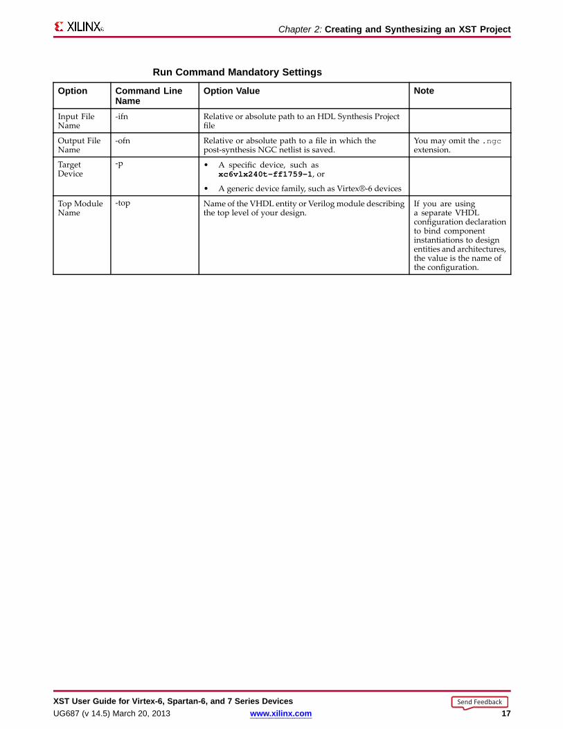
Run Command Mandator y Settings
Option Command LineName
Option Value Note
Input FileName
-ifn Relative or absolute path to an HDL Synthesis Projectfile
Output FileName
-ofn Relative or absolute path to a file in which thepost-synthesis NGC netlist is saved.
You may omit the .ngcextension.
TargetDevice
-p • A specific device, such asxc6vlx240t-ff1759-1 , or
• A generic device family, such as Virtex®-6 devices
Top ModuleName
-top Name of the VHDL entity or Verilog module describingthe top level of your design.
If you are usinga separate VHDLconfiguration declarationto bind componentinstantiations to designentities and architectures,the value is the name ofthe configuration.
XST User Guide for Vir tex-6, Spar tan-6, and 7 Series DevicesUG687 (v 14.5) March 20, 2013 www.xilinx.com 17
Send Feedback

Chapter 2: Creating and Synthesizing an XST Project
Run Command Optional Settings
Option Command Line NameVHDL Top Level Architecture (Name of the specificVHDL architecture to be tied to the top level VHDL entity.Not applicable if the top level of your design is describedin Verilog.)
-ent
Optimization Goal -opt_mode
Optimization Effort -opt_level
Power Reduction -power
Use Synthesis Constraints File -iuc
Synthesis Constraints File -uc
Keep Hierarchy -keep_hierarchy
Netlist Hierarchy -netlist_hierarchy
Global Optimization Goal -glob_opt
Generate RTL Schematic -rtlview
Read Cores -read_cores
Cores Search Directories -sd
Write Timing Constraints -write_timing_constraints
Cross Clock Analysis -cross_clock_analysis
Hierarchy Separator -hierarchy_separator
Bus Delimiter -bus_delimiter
LUT-FF Pairs Utilization Ratio -slice_utilization_ratio
BRAM Utilization Ratio -bram_utilization_ratio
DSP Utilization Ratio -dsp_utilization_ratio
Case -case
Library Search Order -lso
Verilog Include Directories -vlgincdir
Generics -generics
Verilog Macros -define
FSM Extraction -fsm_extract
FSM Encoding Algorithm -fsm_encoding
Safe Implementation -safe_implementation
Case Implementation Style -vlgcase
FSM Style -fsm_style
RAM Extraction -ram_extract
RAM Style -ram_style
ROM Extraction -rom_extract
ROM Style -rom_style
Automatic BRAM Packing -auto_bram_packing
Shift Register Extraction -shreg_extract
XST User Guide for Vir tex-6, Spar tan-6, and 7 Series Devices18 www.xilinx.com UG687 (v 14.5) March 20, 2013
Send Feedback

Chapter 2: Creating and Synthesizing an XST Project
Option Command Line NameShift Register Minimum Size -shreg_min_size
Resource Sharing -resource_sharing
Use DSP Block -use_dsp48
Asynchronous To Synchronous -async_to_sync
Add I/O Buffers -iobuf
Max Fanout -max_fanout
Number of Clock Buffers -bufg
Register Duplication -register_duplication
Equivalent Register Removal -equivalent_register_removal
Register Balancing -register_balancing
Move First Flip-Flop Stage -move_first_stage
Move Last Flip-Flop Stage -move_last_stage
Pack I/O Registers into IOBs -iob
LUT Combining -lc
Reduce Control Sets -reduce_control_sets
Use Clock Enable -use_clock_enable
Use Synchronous Set -use_sync_set
Use Synchronous Reset -use_sync_reset
Optimize Instantiated Primitives -optimize_primitives
XST User Guide for Vir tex-6, Spar tan-6, and 7 Series DevicesUG687 (v 14.5) March 20, 2013 www.xilinx.com 19
Send Feedback
Chapter 2: Creating and Synthesizing an XST Project
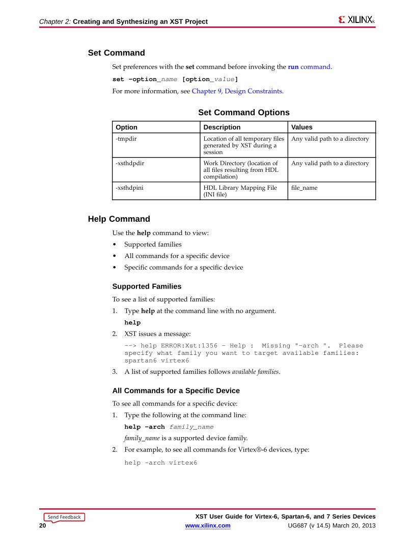
Set CommandSet preferences with the set command before invoking the run command.
set –option_ name [option_ value ]
For more information, see Chapter 9, Design Constraints.
Set Command OptionsOption Description Values-tmpdir Location of all temporary files
generated by XST during asession
Any valid path to a directory
-xsthdpdir Work Directory (location ofall files resulting from HDLcompilation)
Any valid path to a directory
-xsthdpini HDL Library Mapping File(INI file)
file_name
Help CommandUse the help command to view:
• Supported families
• All commands for a specific device
• Specific commands for a specific device
Suppor ted FamiliesTo see a list of supported families:
1. Type help at the command line with no argument.
help
2. XST issues a message:
--> help ERROR:Xst:1356 - Help : Missing "-arch ". Pleasespecify what family you want to target available families:spartan6 virtex6
3. A list of supported families follows available families.
All Commands for a Specific DeviceTo see all commands for a specific device:
1. Type the following at the command line:
help -arch family_name
family_name is a supported device family.
2. For example, to see all commands for Virtex®-6 devices, type:
help -arch virtex6
XST User Guide for Vir tex-6, Spar tan-6, and 7 Series Devices20 www.xilinx.com UG687 (v 14.5) March 20, 2013
Send Feedback
Chapter 2: Creating and Synthesizing an XST Project
Specific Commands for a Specific DeviceTo see information about a specific command for a specific device:1. Type the following at the command line
help -arch family_name -command command_name
• family_name is a supported device family• command_name is one of the following commands:
– run– set– time
2. For example, to see information about the run command for Virtex-6 devices, type:
help -arch virtex6 -command run
Names With Spaces in Command Line ModeXST supports file and directory names with spaces in command line mode.• Enclose file and directory names with spaces in double quotes:
“C:\ my project ”
• For options supporting multiple directories (-sd and -vlgincdir), enclose multipledirectories in {braces}.
-vlgincdir {"C:\ my project " C:\temp}
• In earlier releases of XST, multiple directories were enclosed in double quotes. XSTstill supports this syntax, provided that the directory names do not contain spaces.Xilinx® recommends that you change existing scripts to the new syntax enclosingmultiple directories in {braces}.
Output FilesXST output files include:• Typical Output Files• Temporary Output Files
Typical Output FilesXST generates the following typical output files:
• Output NGC netlist (NGC) (.ngc )– In ISE® Design Suite, the NGC file is created in the project directory.– In command line mode, the NGC file is created in:
♦ The current directory, or♦ Any other directory specified by run -ofn.
• Register Transfer Level (RTL) netlist for the RTL Viewer (NGR) (.ngr )• Synthesis log file (SRP) (.srp )
Temporar y Output Files• XST generates temporary files in the XST TEMP (temp ) directory.• HDL compilation files are generated in the TEMP directory.• The default TEMP directory is the XST subdirectory of the current directory.
XST User Guide for Vir tex-6, Spar tan-6, and 7 Series DevicesUG687 (v 14.5) March 20, 2013 www.xilinx.com 21
Send Feedback

Chapter 2: Creating and Synthesizing an XST Project
Temp Director y LocationsSystem LocationWorkstations /tmp
Windows The directory specified by either the TEMP orTMP environment variable
Changing the Temp Director yTo change the TEMP directory, run set -tmpdir <directory>:
• At the XST prompt, or
• In an XST script file.
Maintaining the Temp Director y• The TEMP directory contains the files resulting from the compilation of all VHDL
and Verilog files during all XST sessions.
• The number of files stored in the TEMP directory can severely impact CPUperformance.
• XST does not automatically clean the TEMP directory. Xilinx® recommends thatyou manually clean the TEMP directory on a regular basis.
XST User Guide for Vir tex-6, Spar tan-6, and 7 Series Devices22 www.xilinx.com UG687 (v 14.5) March 20, 2013
Send Feedback
Chapter 3
VHDL SupportXST supports the VHSIC Hardware Description Language (VHDL) except as otherwisenoted.
• VHDL compactly describes complicated logic.
• VHDL allows you to:
– Describe the structure of a system:
♦ How the system is decomposed into subsystems.
♦ How those subsystems are interconnected.
– Specify the function of a system using familiar programming language forms.
– Simulate a system design before it is implemented and programmed inhardware.
– Produce a detailed, device-dependent version of a design to be synthesized froma more abstract specification.
For more information, see:
• IEEE VHDL Language Reference Manual (LRM)
• Chapter 9, Design Constraints, especially VHDL Attributes
VHDL IEEE Suppor tThe XST parsing and elaboration engine complies with VHDL IEEE 1076-1993.
XST supports non-LRM compliant constructs when the construct:
• Is supported by most synthesis and simulation tools.
• Greatly simplifies coding.
• Does not cause negatively impact synthesis.
• Does not negatively impact quality of results.
Non-LRM Compliant Example• The LRM does not allow instantiation with a port map if:
– A formal port is a buffer, and
– The corresponding effective port is an out.
• XST supports this non-LRM compliant construct. The construct meets the criteriastated above in XST Support for Non-LRM Compliant Constructs.
XST User Guide for Vir tex-6, Spar tan-6, and 7 Series DevicesUG687 (v 14.5) March 20, 2013 www.xilinx.com 23
Send Feedback
Chapter 3: VHDL Suppor t
VHDL Data TypesSome VHDL data types are part of predefined packages.
For information on where they are compiled, and how to load them, see VHDLPredefined Packages.
VHDL Unsuppor ted Data TypesVHDL supports the real type defined in the standard package for calculations only,such as the calculation of generics values.
You cannot define a synthesizable object of type real.
VHDL Data TypesVHDL data types include:
• VHDL Predefined Enumerated Types
• VHDL User-Defined Enumerated Types
• VHDL Bit Vector Types
• VHDL Integer Types
• VHDL Multi-Dimensional Array Types
• VHDL Record Types
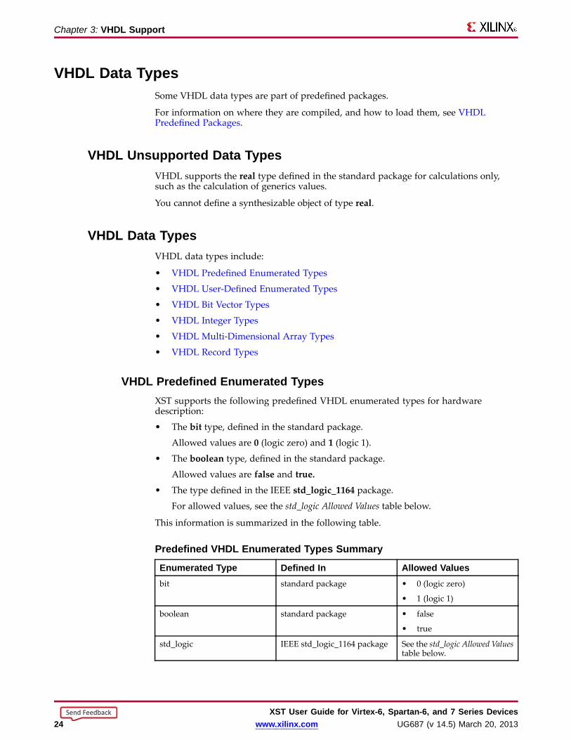
VHDL Predefined Enumerated TypesXST supports the following predefined VHDL enumerated types for hardwaredescription:
• The bit type, defined in the standard package.
Allowed values are 0 (logic zero) and 1 (logic 1).
• The boolean type, defined in the standard package.
Allowed values are false and true.
• The type defined in the IEEE std_logic_1164 package.
For allowed values, see the std_logic Allowed Values table below.
This information is summarized in the following table.
Predefined VHDL Enumerated Types Summar y
Enumerated Type Defined In Allo wed Valuesbit standard package • 0 (logic zero)
• 1 (logic 1)
boolean standard package • false
• true
std_logic IEEE std_logic_1164 package See the std_logic Allowed Valuestable below.
XST User Guide for Vir tex-6, Spar tan-6, and 7 Series Devices24 www.xilinx.com UG687 (v 14.5) March 20, 2013
Send Feedback
Chapter 3: VHDL Suppor t
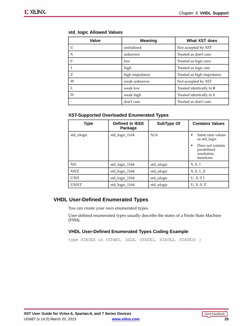
std_logic Allo wed Values
Value Meaning What XST doesU unitialized Not accepted by XST
X unknown Treated as don’t care
0 low Treated as logic zero
1 high Treated as logic one
Z high impedance Treated as high impedance
W weak unknown Not accepted by XST
L weak low Treated identically to 0
H weak high Treated identically to 1- don’t care Treated as don’t care
XST-Suppor ted Overloaded Enumerated Types
Type Defined In IEEEPackage
SubType Of Contains Values
std_ulogic std_logic_1164 N/A • Same nine valuesas std_logic
• Does not containpredefinedresolutionfunctions
X01 std_logic_1164 std_ulogic X, 0, 1
X01Z std_logic_1164 std_ulogic X, 0, 1, Z
UX01 std_logic_1164 std_ulogic U, X, 0 1
UX01Z std_logic_1164 std_ulogic U, X, 0, Z
VHDL User-Defined Enumerated TypesYou can create your own enumerated types.
User-defined enumerated types usually describe the states of a Finite State Machine(FSM).
VHDL User-Defined Enumerated Types Coding Exampletype STATES is (START, IDLE, STATE1, STATE2, STATE3) ;
XST User Guide for Vir tex-6, Spar tan-6, and 7 Series DevicesUG687 (v 14.5) March 20, 2013 www.xilinx.com 25
Send Feedback
Chapter 3: VHDL Suppor t
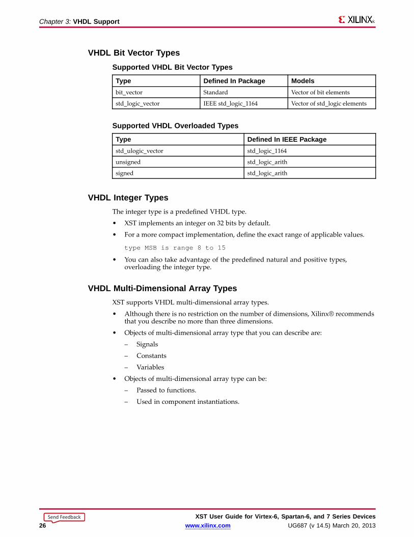
VHDL Bit Vector TypesSuppor ted VHDL Bit Vector Types
Type Defined In Package Modelsbit_vector Standard Vector of bit elements
std_logic_vector IEEE std_logic_1164 Vector of std_logic elements
Suppor ted VHDL Overloaded Types
Type Defined In IEEE Packagestd_ulogic_vector std_logic_1164
unsigned std_logic_arith
signed std_logic_arith
VHDL Integ er TypesThe integer type is a predefined VHDL type.
• XST implements an integer on 32 bits by default.
• For a more compact implementation, define the exact range of applicable values.
type MSB is range 8 to 15
• You can also take advantage of the predefined natural and positive types,overloading the integer type.
VHDL Multi-Dimensional Arra y TypesXST supports VHDL multi-dimensional array types.
• Although there is no restriction on the number of dimensions, Xilinx® recommendsthat you describe no more than three dimensions.
• Objects of multi-dimensional array type that you can describe are:
– Signals
– Constants
– Variables
• Objects of multi-dimensional array type can be:
– Passed to functions.
– Used in component instantiations.
XST User Guide for Vir tex-6, Spar tan-6, and 7 Series Devices26 www.xilinx.com UG687 (v 14.5) March 20, 2013
Send Feedback

Chapter 3: VHDL Suppor t
Full y Constrained Arra y Type Coding ExampleAn array type must be fully constrained in all dimensions.
subtype WORD8is STD_LOGIC_VECTOR(7 downto 0);type TAB12 is array (11 downto 0) of WORD8;type TAB03 is array (2 downto 0) of TAB12;
Array Declared as a Matrix Coding ExampleYou can declare an array as a matrix.
subtype TAB13 is array (7 downto 0,4 downto 0) of STD_LOGIC_VECTOR(8 downto 0);
XST User Guide for Vir tex-6, Spar tan-6, and 7 Series DevicesUG687 (v 14.5) March 20, 2013 www.xilinx.com 27
Send Feedback
Chapter 3: VHDL Suppor t
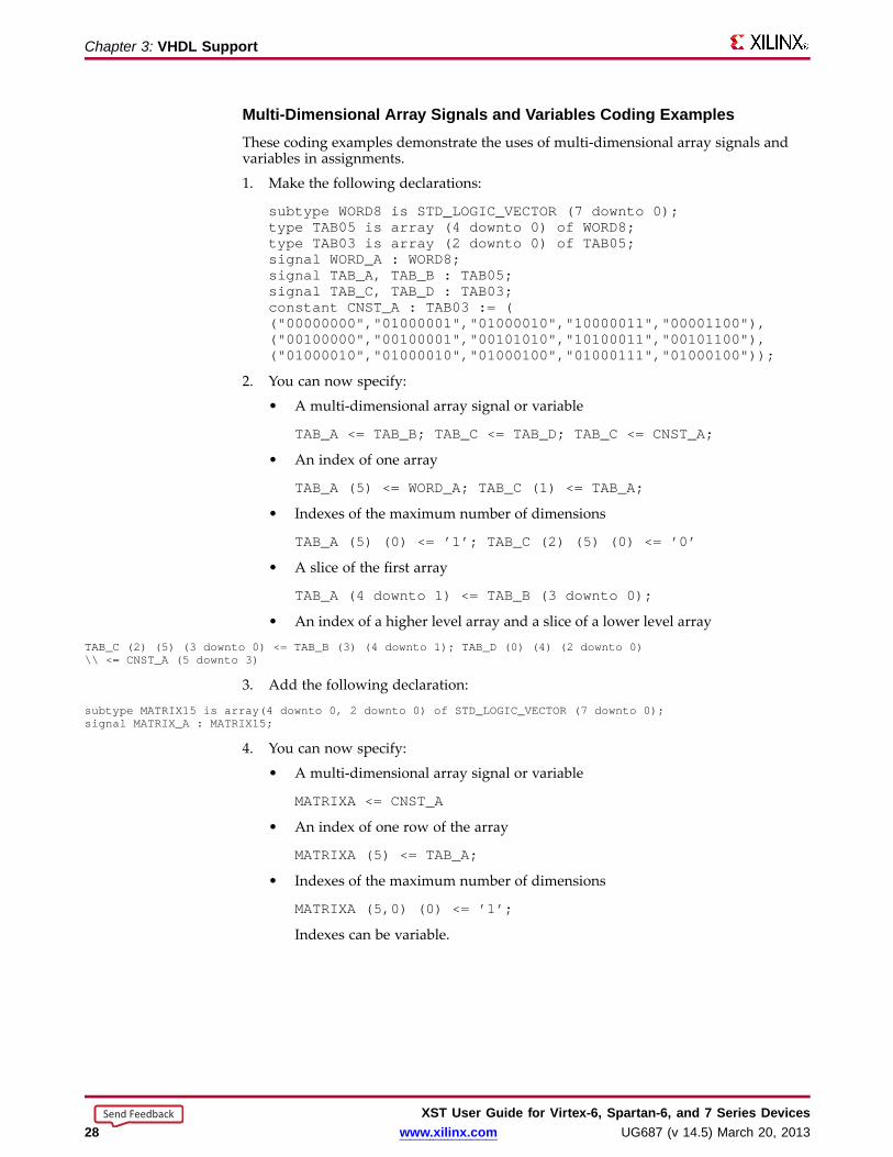
Multi-Dimensional Arra y Signals and Variab les Coding ExamplesThese coding examples demonstrate the uses of multi-dimensional array signals andvariables in assignments.
1. Make the following declarations:
subtype WORD8is STD_LOGIC_VECTOR(7 downto 0);type TAB05 is array (4 downto 0) of WORD8;type TAB03 is array (2 downto 0) of TAB05;signal WORD_A: WORD8;signal TAB_A, TAB_B : TAB05;signal TAB_C, TAB_D : TAB03;constant CNST_A : TAB03 := (("00000000","01000001","01000010","10000011","00001100"),("00100000","00100001","00101010","10100011","00101100"),("01000010","01000010","01000100","01000111","01000100"));
2. You can now specify:
• A multi-dimensional array signal or variable
TAB_A <= TAB_B; TAB_C <= TAB_D; TAB_C <= CNST_A;
• An index of one array
TAB_A (5) <= WORD_A;TAB_C (1) <= TAB_A;
• Indexes of the maximum number of dimensions
TAB_A (5) (0) <= ’1’; TAB_C (2) (5) (0) <= ’0’
• A slice of the first array
TAB_A (4 downto 1) <= TAB_B (3 downto 0);
• An index of a higher level array and a slice of a lower level array
TAB_C (2) (5) (3 downto 0) <= TAB_B (3) (4 downto 1); TAB_D (0) (4) (2 downto 0)\\ <= CNST_A (5 downto 3)
3. Add the following declaration:
subtype MATRIX15 is array(4 downto 0, 2 downto 0) of STD_LOGIC_VECTOR(7 downto 0);signal MATRIX_A : MATRIX15;
4. You can now specify:
• A multi-dimensional array signal or variable
MATRIXA <= CNST_A
• An index of one row of the array
MATRIXA (5) <= TAB_A;
• Indexes of the maximum number of dimensions
MATRIXA (5,0) (0) <= ’1’;
Indexes can be variable.
XST User Guide for Vir tex-6, Spar tan-6, and 7 Series Devices28 www.xilinx.com UG687 (v 14.5) March 20, 2013
Send Feedback

Chapter 3: VHDL Suppor t
VHDL Record Typestype mytype is recordfield1 : std_logic;field2 : std_logic_vector (3 downto 0)end record;
• A field of a record type can also be of type record.
• Constants can be record types.
• Record types cannot contain attributes.
• XST supports aggregate assignments to record signals.
XST User Guide for Vir tex-6, Spar tan-6, and 7 Series DevicesUG687 (v 14.5) March 20, 2013 www.xilinx.com 29
Send Feedback
Chapter 3: VHDL Suppor t
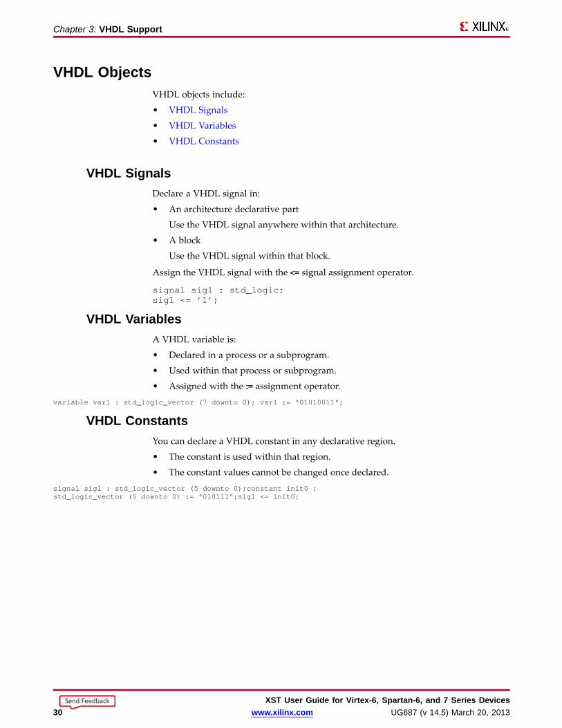
VHDL ObjectsVHDL objects include:
• VHDL Signals
• VHDL Variables
• VHDL Constants
VHDL SignalsDeclare a VHDL signal in:
• An architecture declarative part
Use the VHDL signal anywhere within that architecture.
• A block
Use the VHDL signal within that block.
Assign the VHDL signal with the <= signal assignment operator.
signal sig1 : std_logic;sig1 <= ’1’;
VHDL Variab lesA VHDL variable is:
• Declared in a process or a subprogram.
• Used within that process or subprogram.
• Assigned with the := assignment operator.variable var1 : std_logic_vector (7 downto 0); var1 := "01010011";
VHDL ConstantsYou can declare a VHDL constant in any declarative region.
• The constant is used within that region.
• The constant values cannot be changed once declared.
signal sig1 : std_logic_vector (5 downto 0);constant init0 :std_logic_vector (5 downto 0) := "010111";sig1 <= init0;
XST User Guide for Vir tex-6, Spar tan-6, and 7 Series Devices30 www.xilinx.com UG687 (v 14.5) March 20, 2013
Send Feedback
Chapter 3: VHDL Suppor t
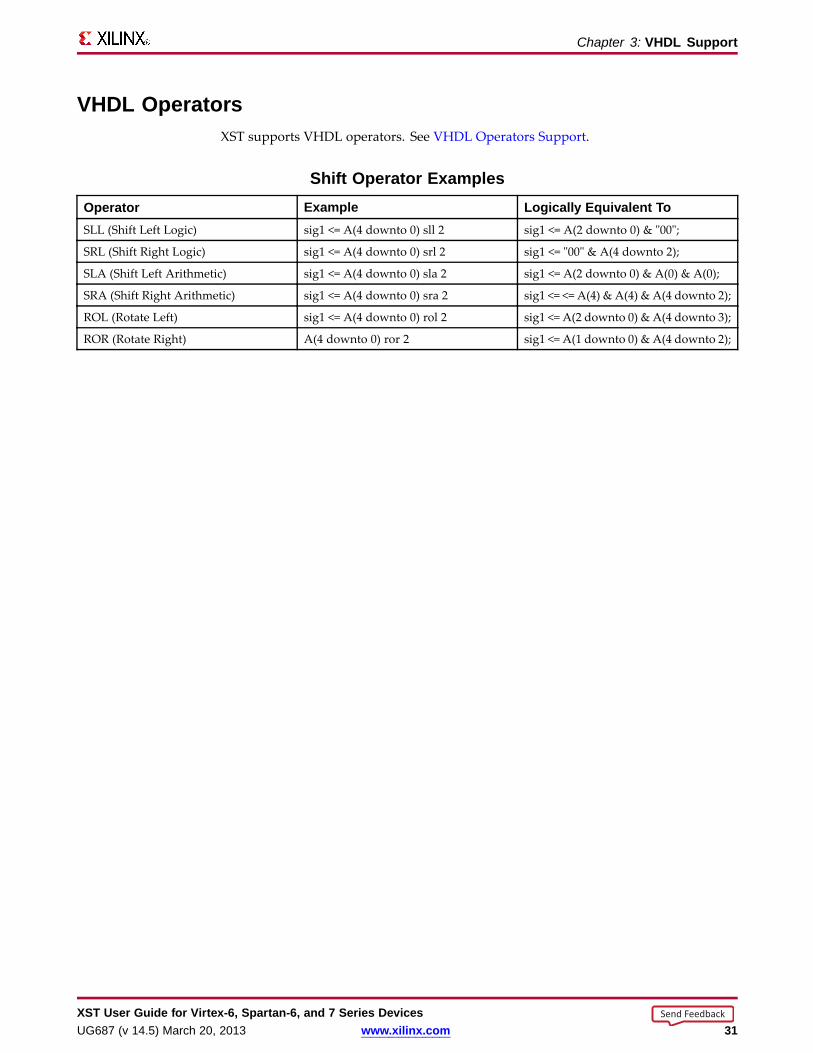
VHDL Operator sXST supports VHDL operators. See VHDL Operators Support.
Shift Operator ExamplesOperator Example Logicall y Equiv alent ToSLL (Shift Left Logic) sig1 <= A(4 downto 0) sll 2 sig1 <= A(2 downto 0) & "00";
SRL (Shift Right Logic) sig1 <= A(4 downto 0) srl 2 sig1 <= "00" & A(4 downto 2);
SLA (Shift Left Arithmetic) sig1 <= A(4 downto 0) sla 2 sig1 <= A(2 downto 0) & A(0) & A(0);
SRA (Shift Right Arithmetic) sig1 <= A(4 downto 0) sra 2 sig1 <= <= A(4) & A(4) & A(4 downto 2);
ROL (Rotate Left) sig1 <= A(4 downto 0) rol 2 sig1 <= A(2 downto 0) & A(4 downto 3);
ROR (Rotate Right) A(4 downto 0) ror 2 sig1 <= A(1 downto 0) & A(4 downto 2);
XST User Guide for Vir tex-6, Spar tan-6, and 7 Series DevicesUG687 (v 14.5) March 20, 2013 www.xilinx.com 31
Send Feedback
Chapter 3: VHDL Suppor t
VHDL Entity and Architecture DescriptionsVHDL entity and architecture descriptions include:
• VHDL Circuit Descriptions
• VHDL Entity Declarations
• VHDL Architecture Declarations
• VHDL Component Instantiation
• VHDL Recursive Component Instantiation
• VHDL Component Configuration
• VHDL Generics
VHDL Circuit DescriptionsA VHDL circuit description (design unit) consists of:
• Entity declaration
– Provides the external view of the circuit.
– Describes objects visible from the outside, including the circuit interface, suchas the I/O ports and generics.
• Architecture
– Provides the internal view of the circuit.
– Describes the circuit behavior or structure.
VHDL Entity DeclarationsThe I/O ports of the circuit are declared in the entity.
Each port has a:
• name
• mode
– in
– out
– inout
– buffer
• type
XST User Guide for Vir tex-6, Spar tan-6, and 7 Series Devices32 www.xilinx.com UG687 (v 14.5) March 20, 2013
Send Feedback

Chapter 3: VHDL Suppor t
Constrained and Unconstrained Por tsPorts can be constrained or unconstrained.
• Ports are usually constrained.
• Ports can be left unconstrained in the entity declaration.
• If ports are left unconstrained, their width is defined at instantiation when theconnection is made between formal ports and actual signals.
• Unconstrained ports allow you to create different instantiations of the same entity,defining different port widths.
• Xilinx® recommends:
– Do not use unconstrained ports.
– Define ports that are constrained through generics.
– Apply different values of those generics at instantiation.
– Do not have an unconstrained port on the top-level entity.
• Array types of more than one-dimension are not accepted as ports.
• The entity declaration can also declare VHDL generics.
Buff er Por t ModeXilinx recommends that you not use buffer port mode.
• VHDL allows buffer port mode when a signal is used both:
– Internally, and
– As an output port when there is only one internal driver.
• Buffer ports:
– Are a potential source of errors during synthesis.
– Complicate validation of post-synthesis results through simulation.
NOT RECOMMENDED Coding Example WITH Buff er Por t Modeentity alu is
port(CLK : in STD_LOGIC;A : in STD_LOGIC_VECTOR(3downto 0);B : in STD_LOGIC_VECTOR(3downto 0);C : buffer STD_LOGIC_VECTOR(3downto 0));
end alu;
architecture behavioral of alu isbegin
process beginif rising_edge(CLK) then
C <= UNSIGNED(A) + UNSIGNED(B) UNSIGNED(C);end if;
end process;end behavioral;
XST User Guide for Vir tex-6, Spar tan-6, and 7 Series DevicesUG687 (v 14.5) March 20, 2013 www.xilinx.com 33
Send Feedback

Chapter 3: VHDL Suppor t
Dropping Buff er ModeXilinx recommends that you drop buffer port mode.
• In the coding example above, signal C:
– Has been modeled with a buffer mode.
– Is used both internally and as an output port.
• Every level of hierarchy that can be connected to C must also be declared as a buffer.
• To drop buffer mode:
1. Insert a dummy signal.
2. Declare port C as an output.
RECOMMENDED Coding Example WITHOUT Buff er Por t Modeentity alu is
port(CLK : in STD_LOGIC;A : in STD_LOGIC_VECTOR(3downto 0);B : in STD_LOGIC_VECTOR(3downto 0);C : out STD_LOGIC_VECTOR(3downto 0));
end alu;
architecture behavioral of alu is-- dummy signalsignal C_INT : STD_LOGIC_VECTOR(3downto 0);
beginC <= C_INT;process begin
if rising_edge(CLK) thenC_INT <= A and B and C_INT;
end if;end process;
end behavioral;
XST User Guide for Vir tex-6, Spar tan-6, and 7 Series Devices34 www.xilinx.com UG687 (v 14.5) March 20, 2013
Send Feedback

Chapter 3: VHDL Suppor t
VHDL Architecture DeclarationsYou can declare internal signals in the architecture.
Each internal signal has a:
• name
• type
VHDL Architecture Declaration Coding Examplelibrary IEEE;use IEEE.std_logic_1164.all;
entity EXAMPLEisport (
A,B,C : in std_logic;D,E : out std_logic );
end EXAMPLE;
architecture ARCHI of EXAMPLEissignal T : std_logic;
begin...
end ARCHI;
XST User Guide for Vir tex-6, Spar tan-6, and 7 Series DevicesUG687 (v 14.5) March 20, 2013 www.xilinx.com 35
Send Feedback

Chapter 3: VHDL Suppor t
VHDL Component InstantiationComponent instantiation allows you to instantiate one design unit (component) insideanother design unit in order to create a hierarchically structured design description.
To perform component instantiation:
1. Create the design unit (entity and architecture) modeling the functionality to beinstantiated.
2. Declare the component to be instantiated in the declarative region of the parentdesign unit architecture.
3. Instantiate and connect this component in the architecture body of the parent designunit.
4. Map (connect) formal ports of the component to actual signals and ports of theparent design unit.
Elements of Component Instantiation StatementThe main elements of a component instantiation statement are:
• Label
Identifies the instance.
• Association list
– Introduced by the reserved port mapkeyword.
– Ties formal ports of the component to actual signals or ports of the parentdesign unit.
• Optional association list
– Introduced by the reserved generic mapkeyword.
– Provides actual values to formal generics defined in the component.
XST supports unconstrained vectors in component declarations.
XST User Guide for Vir tex-6, Spar tan-6, and 7 Series Devices36 www.xilinx.com UG687 (v 14.5) March 20, 2013
Send Feedback
Chapter 3: VHDL Suppor t
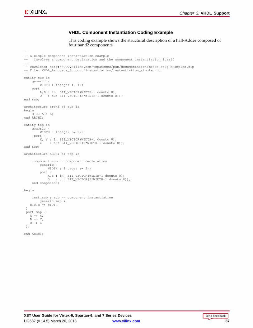
VHDL Component Instantiation Coding ExampleThis coding example shows the structural description of a half-Adder composed offour nand2 components.
---- A simple component instantiation example-- Involves a component declaration and the component instantiation itself---- Download: http://www.xilinx.com/txpatches/pub/documentation/misc/xstug_examples.zip-- File: VHDL_Language_Support/instantiation/instantiation_simple.vhd--entity sub is
generic (WIDTH : integer := 4);
port (A,B : in BIT_VECTOR(WIDTH-1 downto 0);O : out BIT_VECTOR(2*WIDTH-1 downto 0));
end sub;
architecture archi of sub isbegin
O <= A & B;end ARCHI;
entity top isgeneric (
WIDTH : integer := 2);port (
X, Y : in BIT_VECTOR(WIDTH-1 downto 0);Z : out BIT_VECTOR(2*WIDTH-1 downto 0));
end top;
architecture ARCHI of top is
component sub -- component declarationgeneric (
WIDTH : integer := 2);port (
A,B : in BIT_VECTOR(WIDTH-1 downto 0);O : out BIT_VECTOR(2*WIDTH-1 downto 0));
end component;
begin
inst_sub : sub -- component instantiationgeneric map (
WIDTH => WIDTH)port map (A => X,B => Y,O => Z
);
end ARCHI;
XST User Guide for Vir tex-6, Spar tan-6, and 7 Series DevicesUG687 (v 14.5) March 20, 2013 www.xilinx.com 37
Send Feedback
Chapter 3: VHDL Suppor t
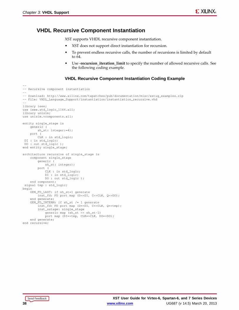
VHDL Recur sive Component InstantiationXST supports VHDL recursive component instantiation.
• XST does not support direct instantiation for recursion.
• To prevent endless recursive calls, the number of recursions is limited by defaultto 64.
• Use -recursion_iteration_limit to specify the number of allowed recursive calls. Seethe following coding example.
VHDL Recur sive Component Instantiation Coding Example---- Recursive component instantiation---- Download: http://www.xilinx.com/txpatches/pub/documentation/misc/xstug_examples.zip-- File: VHDL_Language_Support/instantiation/instantiation_recursive.vhd--library ieee;use ieee.std_logic_1164.all;library unisim;use unisim.vcomponents.all;
entity single_stage isgeneric (
sh_st: integer:=4);port (
CLK : in std_logic;DI : in std_logic;DO : out std_logic );end entity single_stage;
architecture recursive of single_stage iscomponent single_stage
generic (sh_st: integer);
port (CLK : in std_logic;DI : in std_logic;DO : out std_logic );
end component;signal tmp : std_logic;begin
GEN_FD_LAST: if sh_st=1 generateinst_fd: FD port map (D=>DI, C=>CLK, Q=>DO);
end generate;GEN_FD_INTERM: if sh_st /= 1 generate
inst_fd: FD port map (D=>DI, C=>CLK, Q=>tmp);inst_sstage: single_stage
generic map (sh_st => sh_st-1)port map (DI=>tmp, CLK=>CLK, DO=>DO);
end generate;end recursive;
XST User Guide for Vir tex-6, Spar tan-6, and 7 Series Devices38 www.xilinx.com UG687 (v 14.5) March 20, 2013
Send Feedback
Chapter 3: VHDL Suppor t
VHDL Component ConfigurationA component configuration explicitly links a component with the appropriate model.• A model is an entity and architecture pair.• XST supports component configuration in the declarative part of the architecture.
for instantiation_list : component_ name useLibName.entity_ Name(Architecture_ Name);
• The statement below indicates that:– All NAND2 components use the design unit consisting of entity NAND2 and
architecture ARCHI.– The design unit is compiled in the work library.
For all : NAND2 use entity work.NAND2(ARCHI);
• If the configuration clause is missing for a component instantiation:– XST links the component to the entity with the same name (and same interface).– XST links the selected architecture to the most recently compiled architecture.
• XST generates a Black Box during synthesis if no entity or architecture is found.• In command line mode, you may use a dedicated configuration declaration to link
component instantiations to design entities and architectures.• The value of the mandatory Top Module Name (-top) option in the run command is
the configuration name instead of the top level entity name.
VHDL GenericsVHDL generics:• Are the equivalent of Verilog parameters.• Help you create scalable design modelizations.• Allow you to write compact, factorized VHDL code.• Allow you to parameterize functionality such as:
– Bus sizes– The amount of certain repetitive elements in the design unit
Parameteriz e Functionality ExampleFor the same functionality that must be instantiated multiple times, but with differentbus sizes, you need describe only one design unit with generics. See VHDL GenericParameters Coding Example below.
Declaring GenericsYou can declare generic parameters in the entity declaration part.• XST supports all types for generics including:
– integer– boolean– string– real– std_logic_vector
• Declare a generic with a default value.
XST User Guide for Vir tex-6, Spar tan-6, and 7 Series DevicesUG687 (v 14.5) March 20, 2013 www.xilinx.com 39
Send Feedback

Chapter 3: VHDL Suppor t
VHDL Generic Parameter s Coding Example---- VHDL generic parameters example---- Download: http://www.xilinx.com/txpatches/pub/documentation/misc/xstug_examples.zip-- File: VHDL_Language_Support/generics/generics_1.vhd--library IEEE;use IEEE.std_logic_1164.all;use IEEE.std_logic_unsigned.all;
entity addern isgeneric (
width : integer := 8);port (
A,B : in std_logic_vector (width-1 downto 0);Y : out std_logic_vector (width-1 downto 0) );
end addern;
architecture bhv of addern isbegin
Y <= A + B;end bhv;
Library IEEE;use IEEE.std_logic_1164.all;
entity top isport (
X, Y, Z : in std_logic_vector (12 downto 0);A, B : in std_logic_vector (4 downto 0);S :out std_logic_vector (17 downto 0) );end top;
architecture bhv of top iscomponent addern
generic (width : integer := 8);port (
A,B : in std_logic_vector (width-1 downto 0);Y : out std_logic_vector (width-1 downto 0) );
end component;for all : addern use entity work.addern(bhv);
signal C1 : std_logic_vector (12 downto 0);signal C2, C3 : std_logic_vector (17 downto 0);
beginU1 : addern generic map (width=>13) port map (X,Y,C1);C2 <= C1 & A;C3 <= Z & B;U2 : addern generic map (width=>18) port map (C2,C3,S);
end bhv;
XST User Guide for Vir tex-6, Spar tan-6, and 7 Series Devices40 www.xilinx.com UG687 (v 14.5) March 20, 2013
Send Feedback

Chapter 3: VHDL Suppor t
Conflicts Among VHDL Generics and Attrib utesConflicts can arise among VHDL generics and attributes because:
• You can apply VHDL generics and attributes to both instances and components inthe HDL source code.
AND
• You can specify attributes in a constraints file.
Rules for Conflict ResolutionXST resolves the conflicts among VHDL generics and attributes as follows:
• Specifications on an instance (lower level) take precedence over specifications on acomponent (higher level).
• If a generic and an attribute are applicable to the same instance or the samecomponent, the attribute takes precedence over the generic, regardless of where thegeneric was specified.
Do not use both mechanisms to define the same constraint. XST flags suchoccurrences.
• An attribute specified in the XST Constraint File (XCF) takes precedence overattributes or generics specified in the VHDL code.
• Security attributes on the block definition take precedence over any other attributeor generic.
This information is summarized in the following table.
Rules for Conflict Resolution Summar yItem Takes Precedence OverSpecifications on an instance (lower level) Specifications on a component (higher level)
Attribute applied to an instance or component Generic applied to the same instance or the same component
Attribute specified in the XST Constraint File (XCF) Attributes or generics specified in the VHDL code
Security attributes on the block definition Any other attribute or generic
XST User Guide for Vir tex-6, Spar tan-6, and 7 Series DevicesUG687 (v 14.5) March 20, 2013 www.xilinx.com 41
Send Feedback

Chapter 3: VHDL Suppor t
VHDL Combinatorial CircuitsXST supports the following VHDL combinatorial circuits:
• VHDL Concurrent Signal Assignments
• VHDL Generate Statements
• VHDL Combinatorial Processes
VHDL Concurrent Signal AssignmentsCombinatorial logic is described using concurrent signal assignments.
• Concurrent signal assignments are specified in the body of an architecture.
• VHDL supports three types of concurrent signal assignments:
– Simple
– Selected (with-select-when)
– Conditional (when-else)
• You can describe as many concurrent signal assignments as are necessary.
• The order of appearance of the concurrent signal assignments in the architectureis irrelevant.
• All concurrent signal assignments are concurrently active.
• A concurrent signal assignment is re-evaluated when any signal on the right side ofthe assignment changes value.
• The re-evaluated result is assigned to the signal on the left-hand side.
Simple Signal Assignment VHDL Coding ExampleT <= A and B;
Concurrent Selection Assignment VHDL Coding Example---- Concurrent selection assignment in VHDL---- Download: http://www.xilinx.com/txpatches/pub/documentation/misc/xstug_examples.zip-- File: VHDL_Language_Support/combinatorial/concurrent_selected_assignment.vhd--library ieee;use ieee.std_logic_1164.all;
entity concurrent_selected_assignment isgeneric (
width: integer := 8);port (
a, b, c, d : in std_logic_vector (width-1 downto 0);sel : in std_logic_vector (1 downto 0);T : out std_logic_vector (width-1 downto 0) );
end concurrent_selected_assignment;
architecture bhv of concurrent_selected_assignment isbegin
with sel selectT <= a when "00",
b when "01",c when "10",d when others;
end bhv;
XST User Guide for Vir tex-6, Spar tan-6, and 7 Series Devices42 www.xilinx.com UG687 (v 14.5) March 20, 2013
Send Feedback
Chapter 3: VHDL Suppor t
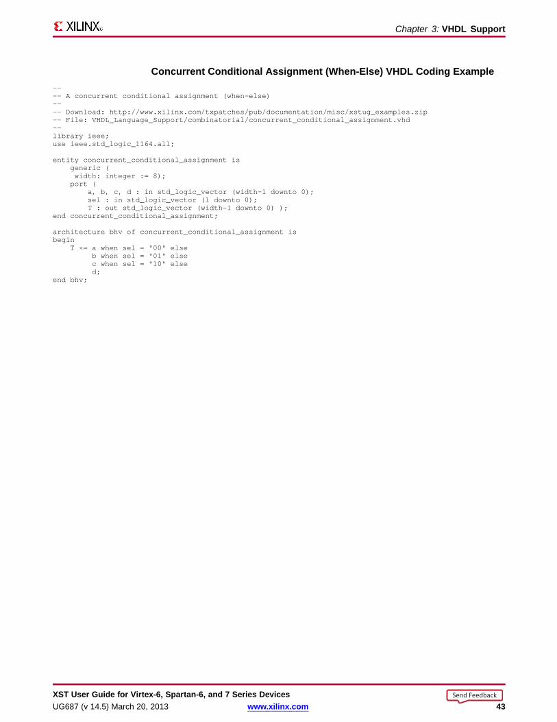
Concurrent Conditional Assignment (When-Else) VHDL Coding Example---- A concurrent conditional assignment (when-else)---- Download: http://www.xilinx.com/txpatches/pub/documentation/misc/xstug_examples.zip-- File: VHDL_Language_Support/combinatorial/concurrent_conditional_assignment.vhd--library ieee;use ieee.std_logic_1164.all;
entity concurrent_conditional_assignment isgeneric (width: integer := 8);port (
a, b, c, d : in std_logic_vector (width-1 downto 0);sel : in std_logic_vector (1 downto 0);T : out std_logic_vector (width-1 downto 0) );
end concurrent_conditional_assignment;
architecture bhv of concurrent_conditional_assignment isbegin
T <= a when sel = "00" elseb when sel = "01" elsec when sel = "10" elsed;
end bhv;
XST User Guide for Vir tex-6, Spar tan-6, and 7 Series DevicesUG687 (v 14.5) March 20, 2013 www.xilinx.com 43
Send Feedback

Chapter 3: VHDL Suppor t
VHDL Generate StatementsVHDL generate statements include:
• VHDL For-Generate Statements
• VHDL If-Generate Statements
VHDL For-Generate StatementsVHDL for-generate statements describe repetitive structures.
For-Generate Statement VHDL Coding ExampleIn this coding example, the for-generate statement describes the calculation of the resultand carry out for each bit position of this 8-bit Adder.
---- A for-generate example---- Download: http://www.xilinx.com/txpatches/pub/documentation/misc/xstug_examples.zip-- File: VHDL_Language_Support/combinatorial/for_generate.vhd--entity for_generate is
port (A,B : in BIT_VECTOR (0 to 7);CIN : in BIT;SUM : out BIT_VECTOR (0 to 7);COUT : out BIT );
end for_generate;
architecture archi of for_generate issignal C : BIT_VECTOR (0 to 8);
beginC(0) <= CIN;COUT<= C(8);LOOP_ADD: for I in 0 to 7 generate
SUM(I) <= A(I) xor B(I) xor C(I);C(I+1) <= (A(I) and B(I)) or (A(I) and C(I)) or (B(I) and C(I));
end generate;end archi;
VHDL If-Generate Statements• An if-generate statement activates specific parts of the HDL source code based on
a test result.
• The if-generate statement is supported for static (non-dynamic) conditions.
If-Generate Example• A generic indicates which device family is being targeted.
• The if-generate statement:
– Tests the value of the generic against a specific device family.
– Activates a section of the HDL source code written specifically for that devicefamily.
XST User Guide for Vir tex-6, Spar tan-6, and 7 Series Devices44 www.xilinx.com UG687 (v 14.5) March 20, 2013
Send Feedback
Chapter 3: VHDL Suppor t
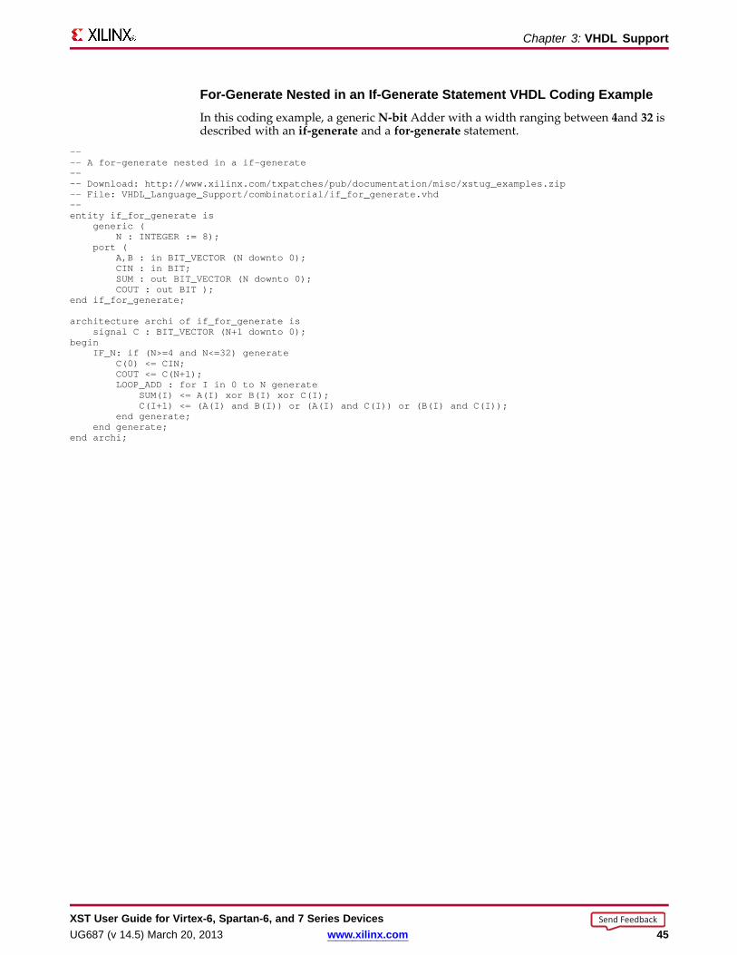
For-Generate Nested in an If-Generate Statement VHDL Coding ExampleIn this coding example, a generic N-bit Adder with a width ranging between 4and 32 isdescribed with an if-generate and a for-generate statement.
---- A for-generate nested in a if-generate---- Download: http://www.xilinx.com/txpatches/pub/documentation/misc/xstug_examples.zip-- File: VHDL_Language_Support/combinatorial/if_for_generate.vhd--entity if_for_generate is
generic (N : INTEGER := 8);
port (A,B : in BIT_VECTOR (N downto 0);CIN : in BIT;SUM : out BIT_VECTOR (N downto 0);COUT : out BIT );
end if_for_generate;
architecture archi of if_for_generate issignal C : BIT_VECTOR (N+1 downto 0);
beginIF_N: if (N>=4 and N<=32) generate
C(0) <= CIN;COUT<= C(N+1);LOOP_ADD: for I in 0 to N generate
SUM(I) <= A(I) xor B(I) xor C(I);C(I+1) <= (A(I) and B(I)) or (A(I) and C(I)) or (B(I) and C(I));
end generate;end generate;
end archi;
XST User Guide for Vir tex-6, Spar tan-6, and 7 Series DevicesUG687 (v 14.5) March 20, 2013 www.xilinx.com 45
Send Feedback

Chapter 3: VHDL Suppor t
VHDL Combinatorial ProcessesVHDL combinatorial logic can be modeled with a process.
• A process is combinatorial when 1) signals assigned in the process, 2) are explicitlyassigned a new value, 3) every time the process is executed.
• No such signal should implicitly retain its current value.• A process can contain local variables.
Memor y ElementsHardware inferred from a combinatorial process does not involve any memory elements.• A process is combinatorial when 1) all assigned signals in a process 2) are always
explicitly assigned 3) in all possible paths within a process block.• A signal that is not explicitly assigned in all branches of an if or case statement
typically leads to a Latch inference.• If XST infers unexpected Latches, review the HDL source code for a signal that is
not explicitly assigned.
Sensitivity ListA combinatorial process has a sensitivity list.• The sensitivity list appears within parentheses after the process keyword.• A process is activated if an event (value change) appears on one of the sensitivity
list signals.• For a combinatorial process, this sensitivity list must contain:
– All signals in conditions (for example, if and case).– All signals on the right-hand side of an assignment.
Missing SignalsSignals may be missing from the sensitivity list.• If one or more signals is missing from the sensitivity list:
– The synthesis results can differ from the initial design specification.– XST issues a warning message.– XST adds the missing signals to the sensitivity list.
• To avoid problems during simulation:– Explicitly add all missing signals in the HDL source code.– Re-run synthesis.
VHDL Variab le and Signal AssignmentsXST supports VHDL variable and signal assignments.• A process can contain local variables.• Local variables are:
– Declared and used within a process.– Generally not visible outside the process.
XST User Guide for Vir tex-6, Spar tan-6, and 7 Series Devices46 www.xilinx.com UG687 (v 14.5) March 20, 2013
Send Feedback
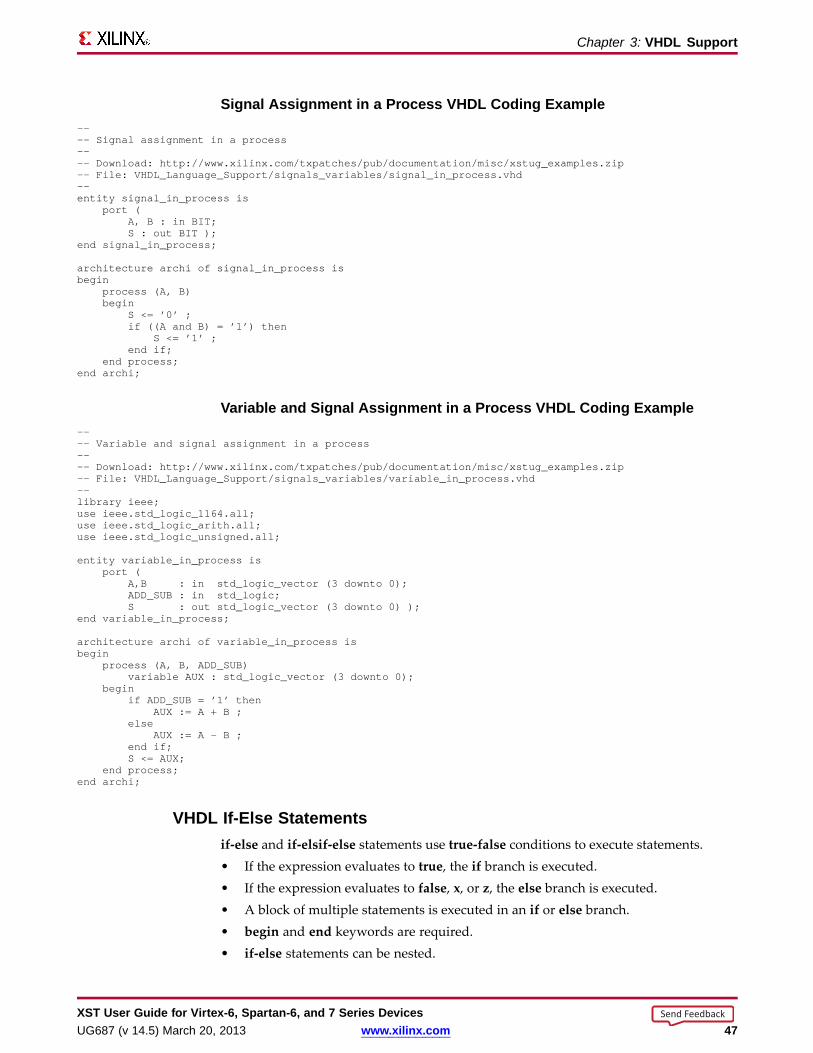
Chapter 3: VHDL Suppor t
Signal Assignment in a Process VHDL Coding Example---- Signal assignment in a process---- Download: http://www.xilinx.com/txpatches/pub/documentation/misc/xstug_examples.zip-- File: VHDL_Language_Support/signals_variables/signal_in_process.vhd--entity signal_in_process is
port (A, B : in BIT;S : out BIT );
end signal_in_process;
architecture archi of signal_in_process isbegin
process (A, B)begin
S <= ’0’ ;if ((A and B) = ’1’) then
S <= ’1’ ;end if;
end process;end archi;
Variab le and Signal Assignment in a Process VHDL Coding Example---- Variable and signal assignment in a process---- Download: http://www.xilinx.com/txpatches/pub/documentation/misc/xstug_examples.zip-- File: VHDL_Language_Support/signals_variables/variable_in_process.vhd--library ieee;use ieee.std_logic_1164.all;use ieee.std_logic_arith.all;use ieee.std_logic_unsigned.all;
entity variable_in_process isport (
A,B : in std_logic_vector (3 downto 0);ADD_SUB: in std_logic;S : out std_logic_vector (3 downto 0) );
end variable_in_process;
architecture archi of variable_in_process isbegin
process (A, B, ADD_SUB)variable AUX : std_logic_vector (3 downto 0);
beginif ADD_SUB= ’1’ then
AUX := A + B ;else
AUX := A - B ;end if;S <= AUX;
end process;end archi;
VHDL If-Else Statementsif-else and if-elsif-else statements use true-false conditions to execute statements.• If the expression evaluates to true, the if branch is executed.• If the expression evaluates to false, x, or z, the else branch is executed.• A block of multiple statements is executed in an if or else branch.• begin and end keywords are required.• if-else statements can be nested.
XST User Guide for Vir tex-6, Spar tan-6, and 7 Series DevicesUG687 (v 14.5) March 20, 2013 www.xilinx.com 47
Send Feedback

Chapter 3: VHDL Suppor t
If-Else Statement VHDL Coding Examplelibrary IEEE;use IEEE.std_logic_1164.all;
entity mux4 isport (
a, b, c, d : in std_logic_vector (7 downto 0);sel1, sel2 : in std_logic;outmux : out std_logic_vector (7 downto 0));
end mux4;
architecture behavior of mux4 isbegin
process (a, b, c, d, sel1, sel2)begin
if (sel1 = ’1’) thenif (sel2 = ’1’) then
outmux <= a;else
outmux <= b;end if;
elseif (sel2 = ’1’) then
outmux <= c;else
outmux <= d;end if;
end if;end process;
end behavior;
XST User Guide for Vir tex-6, Spar tan-6, and 7 Series Devices48 www.xilinx.com UG687 (v 14.5) March 20, 2013
Send Feedback
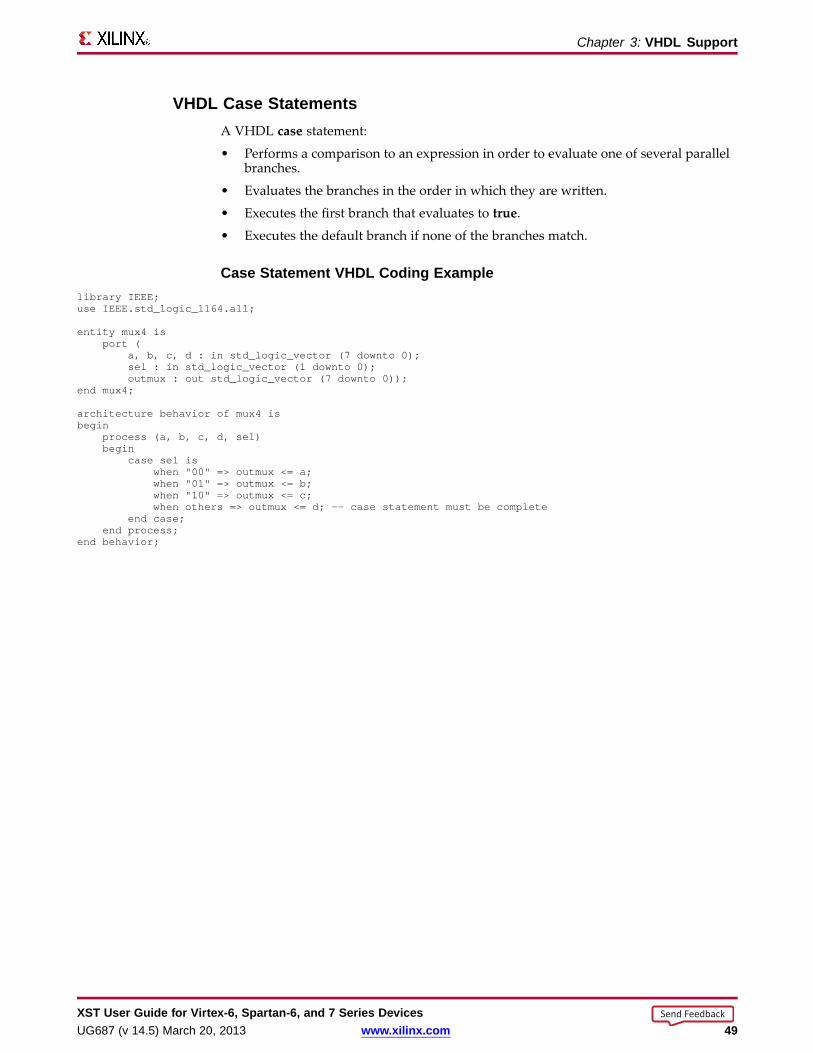
Chapter 3: VHDL Suppor t
VHDL Case StatementsA VHDL case statement:
• Performs a comparison to an expression in order to evaluate one of several parallelbranches.
• Evaluates the branches in the order in which they are written.
• Executes the first branch that evaluates to true.
• Executes the default branch if none of the branches match.
Case Statement VHDL Coding Examplelibrary IEEE;use IEEE.std_logic_1164.all;
entity mux4 isport (
a, b, c, d : in std_logic_vector (7 downto 0);sel : in std_logic_vector (1 downto 0);outmux : out std_logic_vector (7 downto 0));
end mux4;
architecture behavior of mux4 isbegin
process (a, b, c, d, sel)begin
case sel iswhen "00" => outmux <= a;when "01" => outmux <= b;when "10" => outmux <= c;when others => outmux <= d; -- case statement must be complete
end case;end process;
end behavior;
XST User Guide for Vir tex-6, Spar tan-6, and 7 Series DevicesUG687 (v 14.5) March 20, 2013 www.xilinx.com 49
Send Feedback
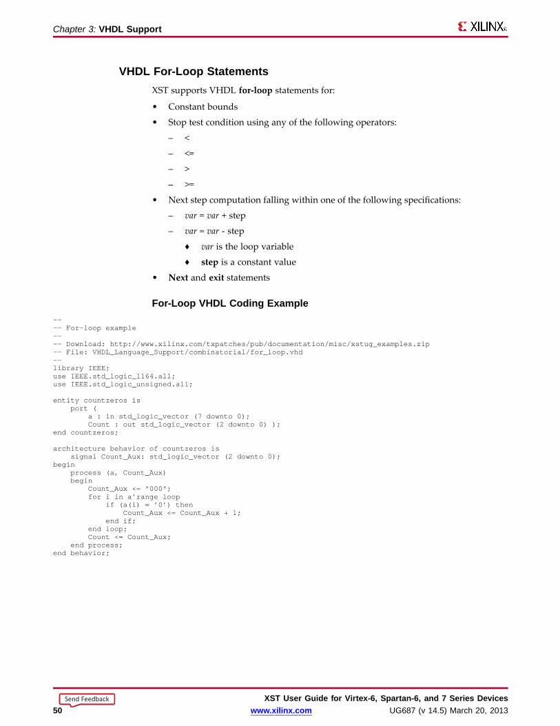
Chapter 3: VHDL Suppor t
VHDL For-Loop StatementsXST supports VHDL for-loop statements for:
• Constant bounds
• Stop test condition using any of the following operators:
– <
– <=
– >
– >=
• Next step computation falling within one of the following specifications:
– var = var + step
– var = var - step
♦ var is the loop variable
♦ step is a constant value
• Next and exit statements
For-Loop VHDL Coding Example---- For-loop example---- Download: http://www.xilinx.com/txpatches/pub/documentation/misc/xstug_examples.zip-- File: VHDL_Language_Support/combinatorial/for_loop.vhd--library IEEE;use IEEE.std_logic_1164.all;use IEEE.std_logic_unsigned.all;
entity countzeros isport (
a : in std_logic_vector (7 downto 0);Count : out std_logic_vector (2 downto 0) );
end countzeros;
architecture behavior of countzeros issignal Count_Aux: std_logic_vector (2 downto 0);
beginprocess (a, Count_Aux)begin
Count_Aux <= "000";for i in a’range loop
if (a(i) = ’0’) thenCount_Aux <= Count_Aux + 1;
end if;end loop;Count <= Count_Aux;
end process;end behavior;
XST User Guide for Vir tex-6, Spar tan-6, and 7 Series Devices50 www.xilinx.com UG687 (v 14.5) March 20, 2013
Send Feedback
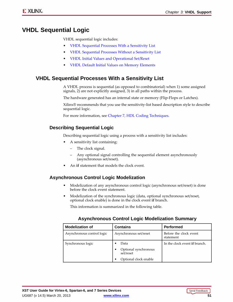
Chapter 3: VHDL Suppor t
VHDL Sequential LogicVHDL sequential logic includes:
• VHDL Sequential Processes With a Sensitivity List
• VHDL Sequential Processes Without a Sensitivity List
• VHDL Initial Values and Operational Set/Reset
• VHDL Default Initial Values on Memory Elements
VHDL Sequential Processes With a Sensitivity ListA VHDL process is sequential (as opposed to combinatorial) when 1) some assignedsignals, 2) are not explicitly assigned, 3) in all paths within the process.
The hardware generated has an internal state or memory (Flip-Flops or Latches).
Xilinx® recommends that you use the sensitivity-list based description style to describesequential logic.
For more information, see Chapter 7, HDL Coding Techniques.
Describing Sequential LogicDescribing sequential logic using a process with a sensitivity list includes:
• A sensitivity list containing:
– The clock signal.
– Any optional signal controlling the sequential element asynchronously(asynchronous set/reset).
• An if statement that models the clock event.
Async hronous Contr ol Logic Modelization• Modelization of any asynchronous control logic (asynchronous set/reset) is done
before the clock event statement.
• Modelization of the synchronous logic (data, optional synchronous set/reset,optional clock enable) is done in the clock event if branch.
This information is summarized in the following table.
Async hronous Contr ol Logic Modelization Summar yModelization of Contains PerformedAsynchronous control logic Asynchronous set/reset Before the clock event
statement
Synchronous logic • Data
• Optional synchronousset/reset
• Optional clock enable
In the clock event if branch.
XST User Guide for Vir tex-6, Spar tan-6, and 7 Series DevicesUG687 (v 14.5) March 20, 2013 www.xilinx.com 51
Send Feedback
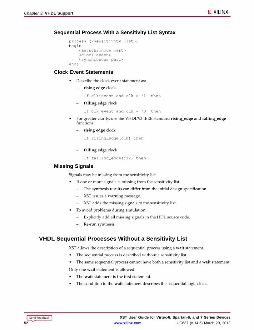
Chapter 3: VHDL Suppor t
Sequential Process With a Sensitivity List Syntaxprocess (<sensitivity list>)begin
<asynchronous part><clock event><synchronous part>
end;
Clock Event Statements• Describe the clock event statement as:
– rising edge clock
If clk’event and clk = ‘1’ then
– falling edge clock
If clk’event and clk = ‘0’ then
• For greater clarity, use the VHDL’93 IEEE standard rising_edge and falling_edgefunctions.
– rising edge clock
If rising_edge(clk) then
– falling edge clock
If falling_edge(clk) then
Missing SignalsSignals may be missing from the sensitivity list.
• If one or more signals is missing from the sensitivity list:
– The synthesis results can differ from the initial design specification.
– XST issues a warning message.
– XST adds the missing signals to the sensitivity list.
• To avoid problems during simulation:
– Explicitly add all missing signals in the HDL source code.
– Re-run synthesis.
VHDL Sequential Processes Without a Sensitivity ListXST allows the description of a sequential process using a wait statement.
• The sequential process is described without a sensitivity list.
• The same sequential process cannot have both a sensitivity list and await statement.
Only one wait statement is allowed.
• The wait statement is the first statement.
• The condition in the wait statement describes the sequential logic clock.
XST User Guide for Vir tex-6, Spar tan-6, and 7 Series Devices52 www.xilinx.com UG687 (v 14.5) March 20, 2013
Send Feedback
Chapter 3: VHDL Suppor t
VHDL Sequential Process Using a Wait Statement Coding Exampleprocessbegin
wait until rising_edge(clk);q <= d;
end process;
Describing a Clock Enable in the Wait Statement Coding ExampleA clock enable can be described in the wait statement together with the clock.
processbegin
wait until rising_edge(clk) and clken = ’1’;q <= d;
end process;
Describing a Clock Enable After the Wait Statement Coding ExampleYou can describe the clock enable separately.
processbegin
wait until rising_edge(clk);if clken = ’1’ then
q <= d;end if;
end process;
Describing Synchronous Contr ol Logic• Besides the clock enable, this coding method also allows you to describe
synchronous control logic, such as a synchronous reset or set.
• You cannot describe a sequential element with asynchronous control logic using aprocess without a sensitivity list. Only a process with a sensitivity list allows suchfunctionality.
• XST does not allow the description of a Latch based on a wait statement.
• For greater flexibility, Xilinx® recommends that you describe synchronous logicusing a process with a sensitivity list.
XST User Guide for Vir tex-6, Spar tan-6, and 7 Series DevicesUG687 (v 14.5) March 20, 2013 www.xilinx.com 53
Send Feedback
Chapter 3: VHDL Suppor t
VHDL Initial Values and Operational Set/ResetYou can initialize Registers when you declare them.
The initialization value:
• Is a constant.
• May be generated from a function call. For example, loading initial values from anexternal data file.
• Cannot depend on earlier initial values.
• Can be a parameter value propagated to a Register.
Initializing Register s VHDL Coding Example OneThis coding example specifies a power-up value in which:
• The sequential element is initialized when the circuit goes live.
• The circuit global reset is applied.
signal arb_onebit : std_logic := ’0’;signal arb_priority : std_logic_vector(3 downto 0) := "1011";
Initializing Sequential Elements Operationall y• To initialize sequential elements operationally, describe:
– Set/reset values
– Local control logic
• Assign a value to a Register when the Register reset line goes to the appropriatevalue.
• For an example, see the following coding example.
• See Flip-Flops and Registers for more information about the advantages anddisadvantages of:
– Operational set/reset
– Asynchronous versus synchronous set/reset
Initializing Register s VHDL Coding Example Twoprocess (clk, rst)begin
if rst=’1’ thenarb_onebit <= ’0’;
end if;end process;
XST User Guide for Vir tex-6, Spar tan-6, and 7 Series Devices54 www.xilinx.com UG687 (v 14.5) March 20, 2013
Send Feedback

Chapter 3: VHDL Suppor t
Initializing Register s VHDL Coding Example ThreeThis coding example combines power-up initialization and operational reset.
---- Register initialization-- Specifying initial contents at circuit powes-up-- Specifying an operational set/reset---- Download: http://www.xilinx.com/txpatches/pub/documentation/misc/xstug_examples.zip-- File: VHDL_Language_Support/initial/initial_1.vhd--library ieee;use ieee.std_logic_1164.all;
entity initial_1 isPort (
clk, rst : in std_logic;din : in std_logic;dout : out std_logic);
end initial_1;
architecture behavioral of initial_1 issignal arb_onebit : std_logic := ’1’; -- power-up to vcc
begin
process (clk)begin
if (rising_edge(clk)) thenif rst=’1’ then -- local synchronous reset
arb_onebit <= ’0’;else
arb_onebit <= din;end if;
end if;end process;
dout <= arb_onebit;
end behavioral;
VHDL Default Initial Values on Memor y ElementsEvery memory element must come up in a known state.
• Since every memory element must come up in a known state, XST does not applyIEEE standards for initial values in some cases.
• For example:
– In the previous coding example, if arb_onebit is not initialized to 1 (one), XSTassigns it a default of 0 (zero) as its initial state.
– XST does not follow the IEEE standard, where U is the default for std_logic.
InitializationInitialization is the same for both Registers and RAM components.
• XST adheres whenever possible to the IEEE VHDL standard when initializingsignal values.
• If no initial values are supplied in the VHDL code, XST uses the default values(where possible) shown in the XST column in the VHDL Initial Values table below.
XST User Guide for Vir tex-6, Spar tan-6, and 7 Series DevicesUG687 (v 14.5) March 20, 2013 www.xilinx.com 55
Send Feedback
Chapter 3: VHDL Suppor t
Unconnected Por tsUnconnected output ports default to the values shown in the XST column in the VHDLInitial Values table below.
• If the output port has an initial condition, XST ties the unconnected output port tothe explicitly-defined initial condition.
• The IEEE VHDL specification does not allow unconnected input ports.
– XST issues an error message for an unconnected input port.
– Even the open keyword is not sufficient for an unconnected input port.
VHDL Initial ValuesType IEEE XST
bit 0 0
std_logic U 0
bit_vector (3 downto 0) 0 0
std_logic_vector (3 downto 0) 0 0
integer (unconstrained) integer’left integer’left
integer range 7 downto 0 integer’left = 7 integer’left = 7 (coded as 111)
integer range 0 to 7 integer’left = 0 integer’left = 0 (coded as 000)
Boolean FALSE FALSE (coded as 0)
enum (S0,S1,S2,S3) type’left = S0 type’left = S0 (coded as 000)
XST User Guide for Vir tex-6, Spar tan-6, and 7 Series Devices56 www.xilinx.com UG687 (v 14.5) March 20, 2013
Send Feedback
Chapter 3: VHDL Suppor t
VHDL Functions and ProceduresUse VHDL functions and procedures for blocks that are used multiple times in a design.
• Functions and procedures are declared in:
– The declarative part of an entity
– An architecture
– A package
• A function or procedure consists of:
– A declarative part
– A body
• The declarative part specifies:
– Input parameters
– Output and inout parameters (procedures only)
– Output and inout parameters (procedures only)
• These parameters can be unconstrained. They are not constrained to a given bound.
• The content is similar to the combinatorial process content.
• Resolution functions are not supported except the function defined in the IEEEstd_logic_1164 package.
XST User Guide for Vir tex-6, Spar tan-6, and 7 Series DevicesUG687 (v 14.5) March 20, 2013 www.xilinx.com 57
Send Feedback
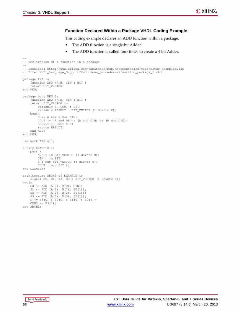
Chapter 3: VHDL Suppor t
Function Declared Within a Package VHDL Coding ExampleThis coding example declares an ADD function within a package.
• The ADD function is a single-bit Adder.
• The ADD function is called four times to create a 4-bit Adder.
---- Declaration of a function in a package---- Download: http://www.xilinx.com/txpatches/pub/documentation/misc/xstug_examples.zip-- File: VHDL_Language_Support/functions_procedures/function_package_1.vhd--package PKG is
function ADD (A,B, CIN : BIT )return BIT_VECTOR;
end PKG;
package body PKG isfunction ADD (A,B, CIN : BIT )return BIT_VECTOR is
variable S, COUT : BIT;variable RESULT : BIT_VECTOR (1 downto 0);
beginS := A xor B xor CIN;COUT := (A and B) or (A and CIN) or (B and CIN);RESULT := COUT& S;return RESULT;
end ADD;end PKG;
use work.PKG.all;
entity EXAMPLEisport (
A,B : in BIT_VECTOR (3 downto 0);CIN : in BIT;S : out BIT_VECTOR (3 downto 0);COUT : out BIT );
end EXAMPLE;
architecture ARCHI of EXAMPLEissignal S0, S1, S2, S3 : BIT_VECTOR (1 downto 0);
beginS0 <= ADD (A(0), B(0), CIN);S1 <= ADD (A(1), B(1), S0(1));S2 <= ADD (A(2), B(2), S1(1));S3 <= ADD (A(3), B(3), S2(1));S <= S3(0) & S2(0) & S1(0) & S0(0);COUT<= S3(1);
end ARCHI;
XST User Guide for Vir tex-6, Spar tan-6, and 7 Series Devices58 www.xilinx.com UG687 (v 14.5) March 20, 2013
Send Feedback

Chapter 3: VHDL Suppor t
Procedure Declared Within a Package VHDL Coding ExampleFollowing is the same example using a procedure.
---- Declaration of a procedure in a package---- Download: http://www.xilinx.com/txpatches/pub/documentation/misc/xstug_examples.zip-- File: VHDL_Language_Support/functions_procedures/procedure_package_1.vhd--package PKG is
procedure ADD (A, B, CIN : in BIT;C : out BIT_VECTOR (1 downto 0) );
end PKG;
package body PKG isprocedure ADD (
A, B, CIN : in BIT;C : out BIT_VECTOR (1 downto 0)
) isvariable S, COUT : BIT;
beginS := A xor B xor CIN;COUT := (A and B) or (A and CIN) or (B and CIN);C := COUT& S;
end ADD;end PKG;
use work.PKG.all;
entity EXAMPLEisport (
A,B : in BIT_VECTOR (3 downto 0);CIN : in BIT;S : out BIT_VECTOR (3 downto 0);COUT : out BIT );
end EXAMPLE;
architecture ARCHI of EXAMPLEisbegin
process (A,B,CIN)variable S0, S1, S2, S3 : BIT_VECTOR (1 downto 0);
beginADD (A(0), B(0), CIN, S0);ADD (A(1), B(1), S0(1), S1);ADD (A(2), B(2), S1(1), S2);ADD (A(3), B(3), S2(1), S3);S <= S3(0) & S2(0) & S1(0) & S0(0);COUT<= S3(1);
end process;end ARCHI;
Recur sive Functions VHDL Coding ExampleXST supports recursive functions. This coding example models an n! function.
function my_func(x : integer) return integer isbegin
if x = 1 thenreturn x;
elsereturn (x*my_func(x-1));
end if;end function my_func;
XST User Guide for Vir tex-6, Spar tan-6, and 7 Series DevicesUG687 (v 14.5) March 20, 2013 www.xilinx.com 59
Send Feedback

Chapter 3: VHDL Suppor t
VHDL Asser t StatementsVHDL assert statements.
• Help you debug your design.
• Enable you to detect undesirable conditions, such as bad values for:
– Generics, constants, and generate conditions.
– Parameters in called functions.
For any failed condition in an assert statement, depending on the severity level, XSTeither:
• Issues a warning message, or
• Rejects the design and issues an error message.
XST supports the assert statement only with static condition.
Using an Asser t Statement for Design Rule CheckingThe coding example below contains a block (SINGLE_SRL) that describes a ShiftRegister.
• The size of the Shift Register depends on the SRL_WIDTH generic value.
• The assert statement ensures that the implementation of a single Shift Register doesnot exceed the size of a single Shift Register LUT (SRL).
• The maximum size of the Shift Register cannot exceed 17 bits, since:
– The size of the SRL is 16 bit, and
– XST implements the last stage of the Shift Register using a Flip-Flop in a slice.
• The SINGLE_SRL block is instantiated twice in the entity named TOP:
– First instantiation
SRL_WIDTH = 13
– Second instantiation
SRL_WIDTH = 18
XST User Guide for Vir tex-6, Spar tan-6, and 7 Series Devices60 www.xilinx.com UG687 (v 14.5) March 20, 2013
Send Feedback

Chapter 3: VHDL Suppor t
Using an Asser t Statement for Design Rule Checking VHDL CodingExample
---- Use of an assert statement for design rule checking---- Download: http://www.xilinx.com/txpatches/pub/documentation/misc/xstug_examples.zip-- File: VHDL_Language_Support/asserts/asserts_1.vhd--library ieee;use ieee.std_logic_1164.all;
entity SINGLE_SRL isgeneric (SRL_WIDTH : integer := 24);port (
clk : in std_logic;inp : in std_logic;outp : out std_logic);
end SINGLE_SRL;
architecture beh of SINGLE_SRL issignal shift_reg : std_logic_vector (SRL_WIDTH-1 downto 0);
beginassert SRL_WIDTH <= 17report "The size of Shift Register exceeds the size of a single SRL"severity FAILURE;
process (clk)begin
if rising_edge(clk) thenshift_reg <= shift_reg (SRL_WIDTH-2 downto 0) & inp;
end if;end process;
outp <= shift_reg(SRL_WIDTH-1);end beh;
library ieee;use ieee.std_logic_1164.all;
entity TOP isport (
clk : in std_logic;inp1, inp2 : in std_logic;outp1, outp2 : out std_logic);
end TOP;
architecture beh of TOP iscomponent SINGLE_SRL is
generic (SRL_WIDTH : integer := 16);port(
clk : in std_logic;inp : in std_logic;outp : out std_logic);
end component;begin
inst1: SINGLE_SRLgeneric map (SRL_WIDTH => 13)port map(
clk => clk,inp => inp1,outp => outp1 );
inst2: SINGLE_SRLgeneric map (SRL_WIDTH => 18)port map(
clk => clk,inp => inp2,outp => outp2 );
end beh;
XST User Guide for Vir tex-6, Spar tan-6, and 7 Series DevicesUG687 (v 14.5) March 20, 2013 www.xilinx.com 61
Send Feedback
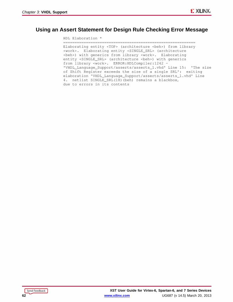
Chapter 3: VHDL Suppor t
Using an Asser t Statement for Design Rule Checking Error MessageHDL Elaboration *==========================================================Elaborating entity <TOP> (architecture <beh>) from library<work>. Elaborating entity <SINGLE_SRL> (architecture<beh>) with generics from library <work>. Elaboratingentity <SINGLE_SRL> (architecture <beh>) with genericsfrom library <work>. ERROR:HDLCompiler:1242 -"VHDL_Language_Support/asserts/asserts_1.vhd" Line 15: "The sizeof Shift Register exceeds the size of a single SRL": exitingelaboration "VHDL_Language_Support/asserts/asserts_1.vhd" Line4. netlist SINGLE_SRL(18)(beh) remains a blackbox,due to errors in its contents
XST User Guide for Vir tex-6, Spar tan-6, and 7 Series Devices62 www.xilinx.com UG687 (v 14.5) March 20, 2013
Send Feedback
Chapter 3: VHDL Suppor t
VHDL Libraries and PackagesVHDL libraries and packages include:
• VHDL Libraries
• VHDL Predefined Packages
VHDL LibrariesA VHDL library is a directory in which design units are compiled.
• Design units are entity or architectures and packages.
• Each VHDL and Verilog source file is compiled in a designated library.
• See Creating an HDL Synthesis Project for information on:
– The syntax of the HDL synthesis project file.
– How to specify the library in which an HDL source file is compiled.
• Invoke a design unit compiled in a library from any VHDL source file. Reference itthrough a library clause.
library library_name ;
• The work library:
– Is the default library.
– Does not require a library clause.
• To change the name of the default library, use:
run -work_lib
• The physical location of the default library, and of any other user-defined library,is a subdirectory with the same name located under a directory defined by theWork Directory constraint.
VHDL Predefined PackagesXST supports the following VHDL predefined packages:
• VHDL Predefined Standard Packages
• VHDL Predefined IEEE Packages
VHDL predefined packages:
• Are defined in the std and ieee standard libraries.
• Are pre-compiled.
• Need not be user-compiled.
• Can be directly included in the HDL source code.
XST User Guide for Vir tex-6, Spar tan-6, and 7 Series DevicesUG687 (v 14.5) March 20, 2013 www.xilinx.com 63
Send Feedback
Chapter 3: VHDL Suppor t
VHDL Predefined Standar d PackagesVHDL predefined standard packages:
• Are included by default.
• Define basic VHDL types:
– bit
– bit_vector
– integer
– natural
– real
– boolean
VHDL Predefined IEEE PackagesXST supports some VHDL predefined IEEE packages.
VHDL predefined IEEE packages:
• Are pre-compiled in the IEEE library.
• Define common data types, functions, and procedures.
XST supports the following IEEE packages:
• numeric_bit
– Unsigned and signed vector types based on bit.
– Overloaded arithmetic operators, conversion functions, and extended functionsfor these types.
• std_logic_1164
– std_logic, std_ulogic, std_logic_vector, and std_ulogic_vector types.
– Conversion functions based on these types.
• std_logic_arith (Synopsys)
– Unsigned and signed vector types based on std_logic.
– Overloaded arithmetic operators, conversion functions, and extended functionsfor these types.
• numeric_std
– Unsigned and signed vector types based on std_logic.
– Overloaded arithmetic operators, conversion functions, and extended functionsfor these types. Equivalent to std_logic_arith.
• std_logic_unsigned (Synopsys)
Unsigned arithmetic operators for std_logic and std_logic_vector
• std_logic_signed (Synopsys)
Signed arithmetic operators for std_logic and std_logic_vector
• std_logic_misc (Synopsys)
Supplemental types, subtypes, constants, and functions for the std_logic_1164package, such as and_reduce and or_reduce
XST User Guide for Vir tex-6, Spar tan-6, and 7 Series Devices64 www.xilinx.com UG687 (v 14.5) March 20, 2013
Send Feedback

Chapter 3: VHDL Suppor t
Defining Your Own VHDL PackagesYou can define your own VHDL packages to specify:• Types and subtypes• Constants• Functions and procedures• Component declarations
Defining a VHDL package permits access to shared definitions and models from otherparts of your project.
Defining a VHDL package requires a:• Package declaration
Declares each of the elements listed above.• Package body
Describes the functions and procedures declared in the package declaration.
Package Declaration Syntaxpackage mypackage is
type mytype isrecordfirst : integer;second : integer;
end record;
constant myzero : mytype := (first => 0, second => 0);
function getfirst (x : mytype) return integer;
end mypackage;
Package Body Syntaxpackage body mypackage is
function getfirst (x : mytype) return integer isbeginreturn x.first;
end function;
end mypackage;
Accessing VHDL PackagesTo access a VHDL package:1. Use a library clause to include the library in which the package has been compiled.
library library_name ;
2. Designate the package, or a specific definition contained in the package, with ause clause.use library_name . package_name .all;
3. Insert these lines immediately before the entity or architecture in which you usethe package definitions.
Because the work library is the default library, you can omit the library clause if thedesignated package has been compiled into this library.
XST User Guide for Vir tex-6, Spar tan-6, and 7 Series DevicesUG687 (v 14.5) March 20, 2013 www.xilinx.com 65
Send Feedback

Chapter 3: VHDL Suppor t
VHDL File Type Suppor tFunction Package
file (type text only) standard
access (type line only) standard
file_open (file, name, open_kind) standard
file_close (file) standard
endfile (file) standard
text std.textio
line std.textio
width std.textio
readline (text, line) std.textio
readline (line, bit, boolean) std.textio
read (line, bit) std.textio
readline (line, bit_vector, boolean) std.textio
read (line, bit_vector) std.textio
read (line, boolean, boolean) std.textio
read (line, boolean) std.textio
read (line, character, boolean) std.textio
read (line, character) std.textio
read (line, string, boolean) std.textio
read (line, string) std.textio
write (file, line) std.textio
write (line, bit, boolean) std.textio
write (line, bit) std.textio
write (line, bit_vector, boolean) std.textio
write (line, bit_vector) std.textio
write (line, boolean, boolean) std.textio
write (line, boolean) std.textio
write (line, character, boolean) std.textio
write (line, character) std.textio
write (line, integer, boolean) std.textio
write (line, integer) std.textio
write (line, string, boolean) std.textio
write (line, string) std.textio
read (line, std_ulogic, boolean) ieee.std_logic_textio
read (line, std_ulogic) ieee.std_logic_textio
read (line, std_ulogic_vector), boolean ieee.std_logic_textio
read (line, std_ulogic_vector) ieee.std_logic_textio
read (line, std_logic_vector, boolean) ieee.std_logic_textio
XST User Guide for Vir tex-6, Spar tan-6, and 7 Series Devices66 www.xilinx.com UG687 (v 14.5) March 20, 2013
Send Feedback
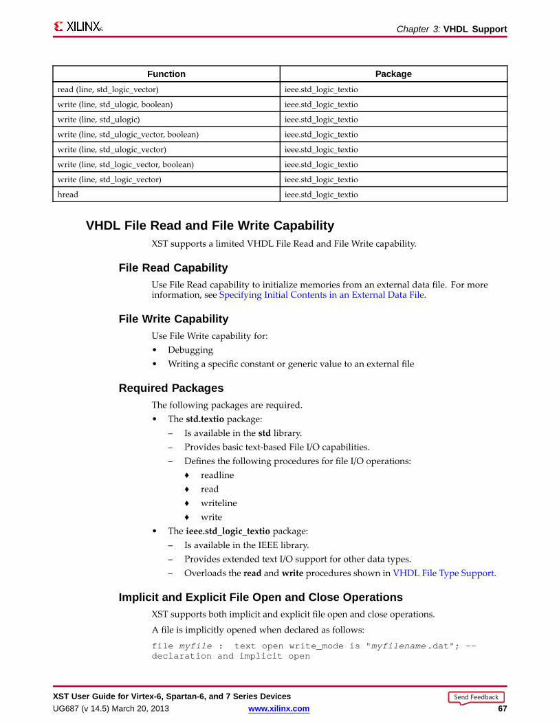
Chapter 3: VHDL Suppor t
Function Packageread (line, std_logic_vector) ieee.std_logic_textio
write (line, std_ulogic, boolean) ieee.std_logic_textio
write (line, std_ulogic) ieee.std_logic_textio
write (line, std_ulogic_vector, boolean) ieee.std_logic_textio
write (line, std_ulogic_vector) ieee.std_logic_textio
write (line, std_logic_vector, boolean) ieee.std_logic_textio
write (line, std_logic_vector) ieee.std_logic_textio
hread ieee.std_logic_textio
VHDL File Read and File Write CapabilityXST supports a limited VHDL File Read and File Write capability.
File Read CapabilityUse File Read capability to initialize memories from an external data file. For moreinformation, see Specifying Initial Contents in an External Data File.
File Write CapabilityUse File Write capability for:• Debugging• Writing a specific constant or generic value to an external file
Required PackagesThe following packages are required.• The std.textio package:
– Is available in the std library.– Provides basic text-based File I/O capabilities.– Defines the following procedures for file I/O operations:
♦ readline♦ read♦ writeline♦ write
• The ieee.std_logic_textio package:– Is available in the IEEE library.– Provides extended text I/O support for other data types.– Overloads the read and write procedures shown in VHDL File Type Support.
Implicit and Explicit File Open and Close OperationsXST supports both implicit and explicit file open and close operations.
A file is implicitly opened when declared as follows:
file myfile : text open write_mode is " myfilename .dat"; --declaration and implicit open
XST User Guide for Vir tex-6, Spar tan-6, and 7 Series DevicesUG687 (v 14.5) March 20, 2013 www.xilinx.com 67
Send Feedback

Chapter 3: VHDL Suppor t
Explicitly open and close an external file as follows:
file myfile : text; -- declaration
variable file_status : file_open_status;
…
file_open (file_status, myfile , " myfilename .dat", write_mode);-- explicit open
…
file_close( myfile ); -- explicit close
Loading Memor y Contents from an External FileSee Specifying RAM Initial Contents in an External Data File.
Writing to a File for DebuggingFor update information, see “Coding Examples” in the Introduction.
XST User Guide for Vir tex-6, Spar tan-6, and 7 Series Devices68 www.xilinx.com UG687 (v 14.5) March 20, 2013
Send Feedback
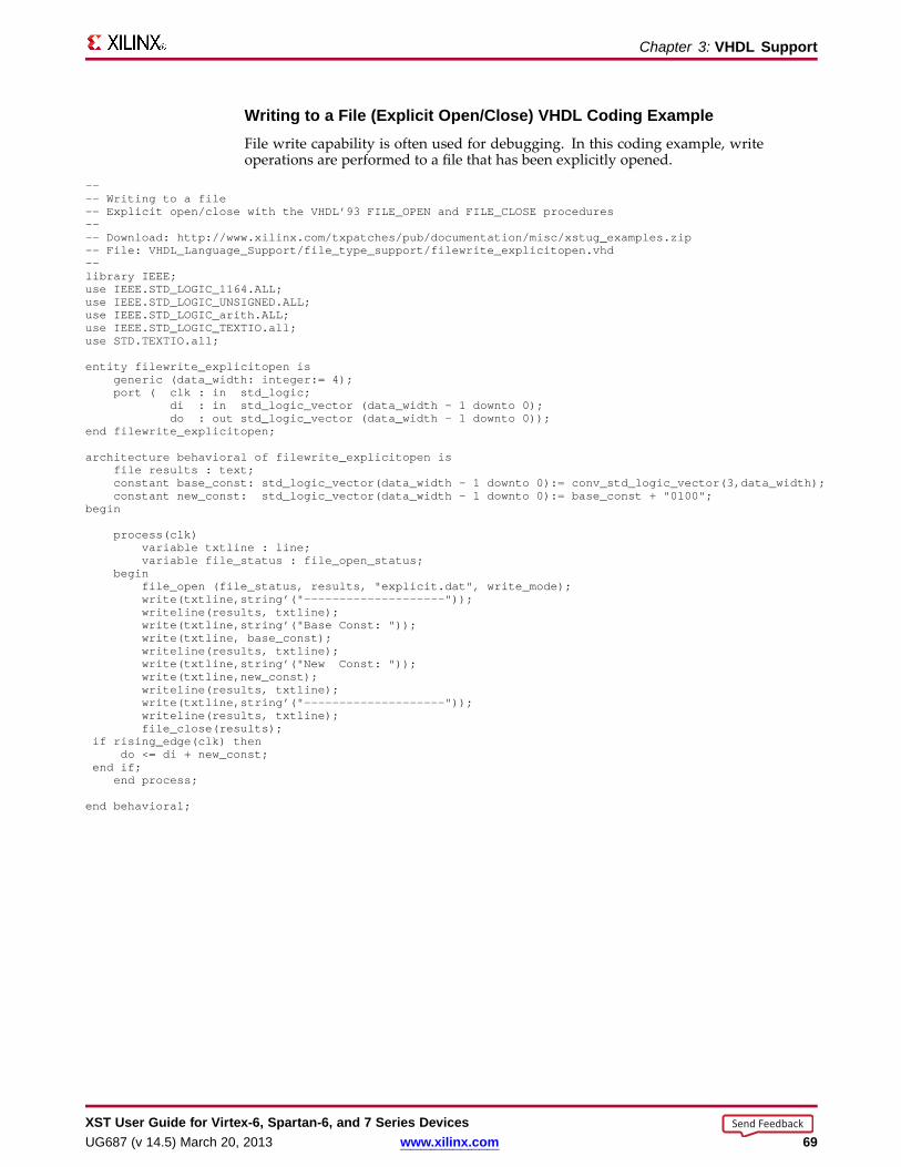
Chapter 3: VHDL Suppor t
Writing to a File (Explicit Open/Close) VHDL Coding ExampleFile write capability is often used for debugging. In this coding example, writeoperations are performed to a file that has been explicitly opened.
---- Writing to a file-- Explicit open/close with the VHDL’93 FILE_OPEN and FILE_CLOSE procedures---- Download: http://www.xilinx.com/txpatches/pub/documentation/misc/xstug_examples.zip-- File: VHDL_Language_Support/file_type_support/filewrite_explicitopen.vhd--library IEEE;use IEEE.STD_LOGIC_1164.ALL;use IEEE.STD_LOGIC_UNSIGNED.ALL;use IEEE.STD_LOGIC_arith.ALL;use IEEE.STD_LOGIC_TEXTIO.all;use STD.TEXTIO.all;
entity filewrite_explicitopen isgeneric (data_width: integer:= 4);port ( clk : in std_logic;
di : in std_logic_vector (data_width - 1 downto 0);do : out std_logic_vector (data_width - 1 downto 0));
end filewrite_explicitopen;
architecture behavioral of filewrite_explicitopen isfile results : text;constant base_const: std_logic_vector(data_width - 1 downto 0):= conv_std_logic_vector(3,data_width);constant new_const: std_logic_vector(data_width - 1 downto 0):= base_const + "0100";
begin
process(clk)variable txtline : line;variable file_status : file_open_status;
beginfile_open (file_status, results, "explicit.dat", write_mode);write(txtline,string’("--------------------"));writeline(results, txtline);write(txtline,string’("Base Const: "));write(txtline, base_const);writeline(results, txtline);write(txtline,string’("New Const: "));write(txtline,new_const);writeline(results, txtline);write(txtline,string’("--------------------"));writeline(results, txtline);file_close(results);
if rising_edge(clk) thendo <= di + new_const;
end if;end process;
end behavioral;
XST User Guide for Vir tex-6, Spar tan-6, and 7 Series DevicesUG687 (v 14.5) March 20, 2013 www.xilinx.com 69
Send Feedback
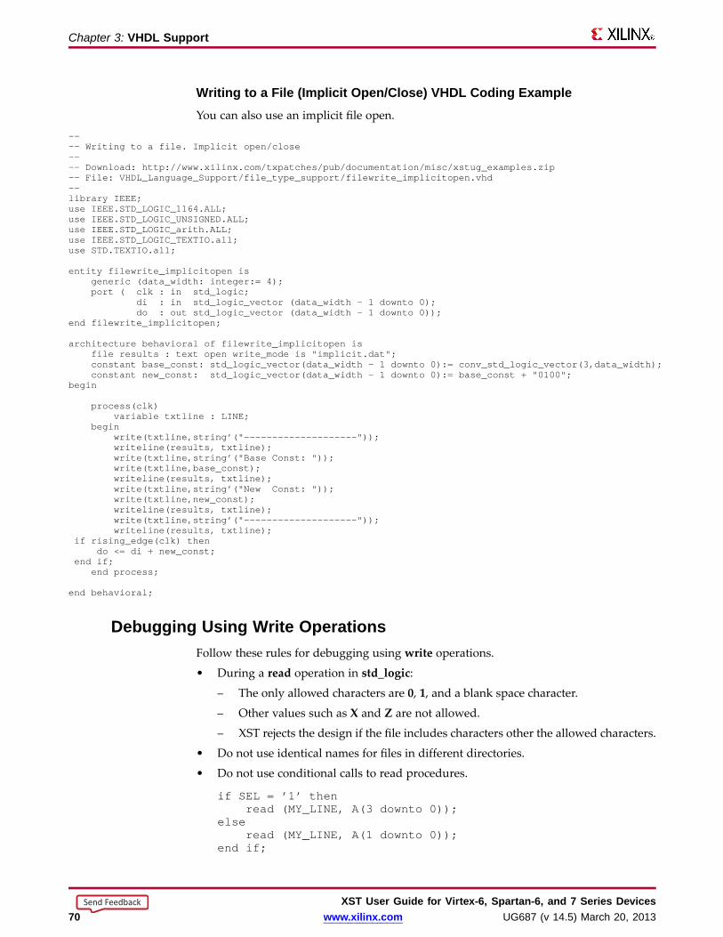
Chapter 3: VHDL Suppor t
Writing to a File (Implicit Open/Close) VHDL Coding ExampleYou can also use an implicit file open.
---- Writing to a file. Implicit open/close---- Download: http://www.xilinx.com/txpatches/pub/documentation/misc/xstug_examples.zip-- File: VHDL_Language_Support/file_type_support/filewrite_implicitopen.vhd--library IEEE;use IEEE.STD_LOGIC_1164.ALL;use IEEE.STD_LOGIC_UNSIGNED.ALL;use IEEE.STD_LOGIC_arith.ALL;use IEEE.STD_LOGIC_TEXTIO.all;use STD.TEXTIO.all;
entity filewrite_implicitopen isgeneric (data_width: integer:= 4);port ( clk : in std_logic;
di : in std_logic_vector (data_width - 1 downto 0);do : out std_logic_vector (data_width - 1 downto 0));
end filewrite_implicitopen;
architecture behavioral of filewrite_implicitopen isfile results : text open write_mode is "implicit.dat";constant base_const: std_logic_vector(data_width - 1 downto 0):= conv_std_logic_vector(3,data_width);constant new_const: std_logic_vector(data_width - 1 downto 0):= base_const + "0100";
begin
process(clk)variable txtline : LINE;
beginwrite(txtline,string’("--------------------"));writeline(results, txtline);write(txtline,string’("Base Const: "));write(txtline,base_const);writeline(results, txtline);write(txtline,string’("New Const: "));write(txtline,new_const);writeline(results, txtline);write(txtline,string’("--------------------"));writeline(results, txtline);
if rising_edge(clk) thendo <= di + new_const;
end if;end process;
end behavioral;
Debugging Using Write OperationsFollow these rules for debugging using write operations.
• During a read operation in std_logic:
– The only allowed characters are 0, 1, and a blank space character.
– Other values such as X and Z are not allowed.
– XST rejects the design if the file includes characters other the allowed characters.
• Do not use identical names for files in different directories.
• Do not use conditional calls to read procedures.
if SEL = ’1’ thenread (MY_LINE, A(3 downto 0));
elseread (MY_LINE, A(1 downto 0));
end if;
XST User Guide for Vir tex-6, Spar tan-6, and 7 Series Devices70 www.xilinx.com UG687 (v 14.5) March 20, 2013
Send Feedback
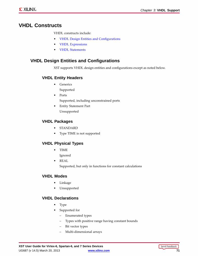
Chapter 3: VHDL Suppor t
VHDL ConstructsVHDL constructs include:
• VHDL Design Entities and Configurations
• VHDL Expressions
• VHDL Statements
VHDL Design Entities and ConfigurationsXST supports VHDL design entities and configurations except as noted below.
VHDL Entity Headers• Generics
Supported
• Ports
Supported, including unconstrained ports
• Entity Statement Part
Unsupported
VHDL Packages• STANDARD
• Type TIME is not supported
VHDL Physical Types• TIME
Ignored
• REAL
Supported, but only in functions for constant calculations
VHDL Modes• Linkage
• Unsupported
VHDL Declarations• Type
• Supported for
– Enumerated types
– Types with positive range having constant bounds
– Bit vector types
– Multi-dimensional arrays
XST User Guide for Vir tex-6, Spar tan-6, and 7 Series DevicesUG687 (v 14.5) March 20, 2013 www.xilinx.com 71
Send Feedback
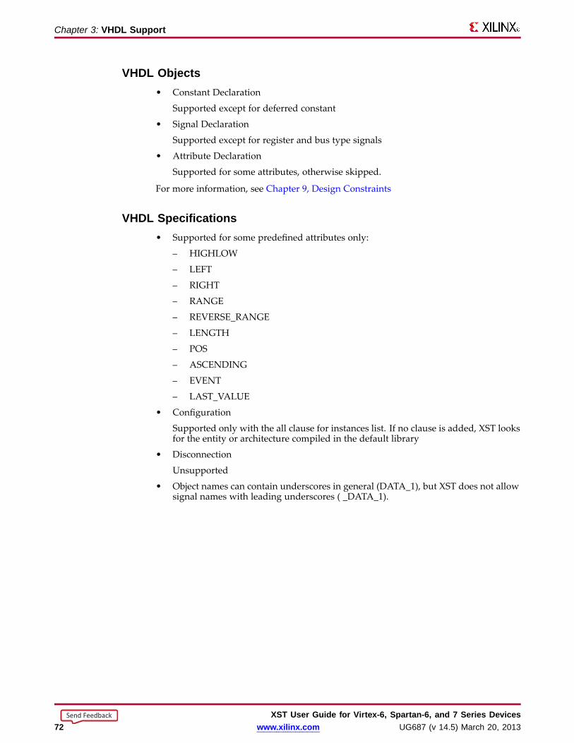
Chapter 3: VHDL Suppor t
VHDL Objects• Constant Declaration
Supported except for deferred constant
• Signal Declaration
Supported except for register and bus type signals
• Attribute Declaration
Supported for some attributes, otherwise skipped.
For more information, see Chapter 9, Design Constraints
VHDL Specifications• Supported for some predefined attributes only:
– HIGHLOW
– LEFT
– RIGHT
– RANGE
– REVERSE_RANGE
– LENGTH
– POS
– ASCENDING
– EVENT
– LAST_VALUE
• Configuration
Supported only with the all clause for instances list. If no clause is added, XST looksfor the entity or architecture compiled in the default library
• Disconnection
Unsupported
• Object names can contain underscores in general (DATA_1), but XST does not allowsignal names with leading underscores ( _DATA_1).
XST User Guide for Vir tex-6, Spar tan-6, and 7 Series Devices72 www.xilinx.com UG687 (v 14.5) March 20, 2013
Send Feedback
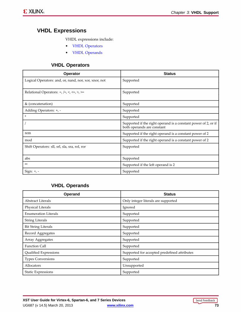
Chapter 3: VHDL Suppor t
VHDL ExpressionsVHDL expressions include:
• VHDL Operators
• VHDL Operands
VHDL Operator sOperator Status
Logical Operators: and, or, nand, nor, xor, xnor, not Supported
Relational Operators: =, /=, <, <=, >, >= Supported
& (concatenation) Supported
Adding Operators: +, - Supported
* Supported
/ Supported if the right operand is a constant power of 2, or ifboth operands are constant
rem Supported if the right operand is a constant power of 2
mod Supported if the right operand is a constant power of 2
Shift Operators: sll, srl, sla, sra, rol, ror Supported
abs Supported
** Supported if the left operand is 2
Sign: +, - Supported
VHDL OperandsOperand Status
Abstract Literals Only integer literals are supported
Physical Literals Ignored
Enumeration Literals Supported
String Literals Supported
Bit String Literals Supported
Record Aggregates Supported
Array Aggregates Supported
Function Call Supported
Qualified Expressions Supported for accepted predefined attributes
Types Conversions Supported
Allocators Unsupported
Static Expressions Supported
XST User Guide for Vir tex-6, Spar tan-6, and 7 Series DevicesUG687 (v 14.5) March 20, 2013 www.xilinx.com 73
Send Feedback
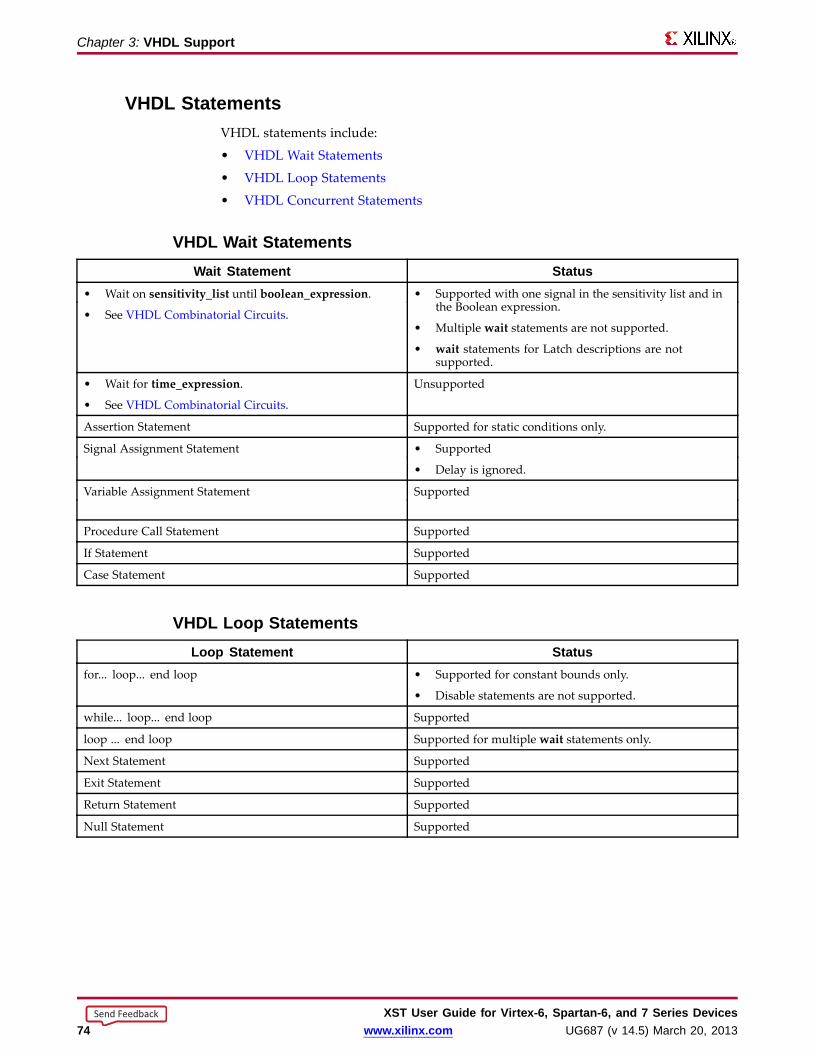
Chapter 3: VHDL Suppor t
VHDL StatementsVHDL statements include:
• VHDL Wait Statements
• VHDL Loop Statements
• VHDL Concurrent Statements
VHDL Wait StatementsWait Statement Status
• Wait on sensitivity_list until boolean_expression.
• See VHDL Combinatorial Circuits.
• Supported with one signal in the sensitivity list and inthe Boolean expression.
• Multiple wait statements are not supported.
• wait statements for Latch descriptions are notsupported.
• Wait for time_expression.
• See VHDL Combinatorial Circuits.
Unsupported
Assertion Statement Supported for static conditions only.
Signal Assignment Statement • Supported
• Delay is ignored.
Variable Assignment Statement Supported
Procedure Call Statement Supported
If Statement Supported
Case Statement Supported
VHDL Loop StatementsLoop Statement Status
for... loop... end loop • Supported for constant bounds only.
• Disable statements are not supported.
while... loop... end loop Supported
loop ... end loop Supported for multiple wait statements only.
Next Statement Supported
Exit Statement Supported
Return Statement Supported
Null Statement Supported
XST User Guide for Vir tex-6, Spar tan-6, and 7 Series Devices74 www.xilinx.com UG687 (v 14.5) March 20, 2013
Send Feedback

Chapter 3: VHDL Suppor t
VHDL Concurrent StatementsConcurrent Statement Status
Process Statement Supported
Concurrent Procedure Call Supported
Concurrent Assertion Statement Ignored
Concurrent Signal Assignment Statement • Supported
• No after clause, no transport or guarded options, nowaveforms
• UNAFFECTED is supported.
Component Instantiation Statement Supported
for-generate Statement supported for constant bounds only
if-generate Statement supported for static condition only
VHDL Reserved Wordsabs access after alias
all and architecture array
assert attribute begin block
body buffer bus case
component configuration constant disconnect
downto else elsif end
entity exit file for
function generate generic group
guarded if impure in
inertial inout is label
library linkage literal loopmap mod nand new
next nor not null
of on open or
others out package port
postponed procedure process pure
range record register rejectrem report return rolror select severity signal
shared sla sll sra
srl subtype then to
transport type unaffected units
until use variable wait
when while with xnor
xor
XST User Guide for Vir tex-6, Spar tan-6, and 7 Series DevicesUG687 (v 14.5) March 20, 2013 www.xilinx.com 75
Send Feedback

XST User Guide for Vir tex-6, Spar tan-6, and 7 Series Devices76 www.xilinx.com UG687 (v 14.5) March 20, 2013
Send Feedback

Chapter 4
Verilog SupportXST supports the Verilog Hardware Description Language (HDL), except as otherwisenoted.
Verilog DesignComplex circuits are often designed using a top down methodology.
• Varying specification levels are required at each stage of the design process. Forexample, at the architectural level, a specification can correspond to a block diagramor an Algorithmic State Machine (ASM) chart.
• A block or ASM stage corresponds to a register transfer block in which theconnections are N-bit wires, such as:
– Register
– Adder
– Counter
– Multiplexer
– Glue logic
– Finite State Machine (FSM)
• Verilog allows the expression of notations such as ASM charts and circuit diagramsin a computer language.
XST User Guide for Vir tex-6, Spar tan-6, and 7 Series DevicesUG687 (v 14.5) March 20, 2013 www.xilinx.com 77
Send Feedback

Chapter 4: Verilog Suppor t
Verilog FunctionalityVerilog provides both behavioral and structural language structures. These structuresallow the expression of design objects at high and low levels of abstraction.
• Designing hardware with Verilog allows the use of software concepts such as:
– Parallel processing
– Object-oriented programming
• Verilog has a syntax similar to C and Pascal.
• XST supports Verilog as IEEE 1364.
• Verilog support in XST allows you to describe the global circuit and each block inthe most efficient style.
– Synthesis is performed with the best synthesis flow for each block.
– Synthesis in this context is the compilation of high-level behavioral andstructural Verilog HDL statements into a flattened gate-level netlist. The netlistcan then be used to custom program a programmable logic device such asa Virtex® device.
– Different synthesis methods are used for:
♦ Arithmetic blocks
♦ Glue logic
♦ Finite State Machine (FSM) components
More Information• For information about basic Verilog concepts, see:
IEEE Verilog HDL Reference Manual
• For information about Behavioral Verilog, see:
Chapter 5, Behavioral Verilog
• For information about XST support for Verilog constructs and meta comments, see:
– Chapter 9, Design Constraints
Verilog design constraints and options
– Verilog–2001 Attributes and Meta Comments
Verilog attribute syntax
– Chapter 10, General Constraints
Setting Verilog options in the Process window of ISE® Design Suite
XST User Guide for Vir tex-6, Spar tan-6, and 7 Series Devices78 www.xilinx.com UG687 (v 14.5) March 20, 2013
Send Feedback

Chapter 4: Verilog Suppor t
Verilog–2001 Suppor tXST supports the following Verilog–2001 features.
• Generate statements
• Combined port/data type declarations
• ANSI-style port list
• Module parameter port lists
• ANSI C style task/function declarations
• Comma-separated sensitivity list
• Combinatorial logic sensitivity
• Default nets with continuous assigns
• Disable default net declarations
• Indexed vector part selects
• Multi-dimensional arrays
• Arrays of net and real data types
• Array bit and part selects
• Signed reg, net, and port declarations
• Signed-based integer numbers
• Signed arithmetic expressions
• Arithmetic shift operators
• Automatic width extension past 32 bits
• Power operator
• N sized parameters
• Explicit in-line parameter passing
• Fixed local parameters
• Enhanced conditional compilation
• File and line compiler directives
• Variable part selects
• Recursive Tasks and Functions
• Constant Functions
For more information, see:
• Sutherland, Stuart. Verilog 2001: A Guide to the New Features of the VERILOG HardwareDescription Language (2002)
• IEEE Standard Verilog Hardware Description Language Manual (IEEE Standard1364-2001)
XST User Guide for Vir tex-6, Spar tan-6, and 7 Series DevicesUG687 (v 14.5) March 20, 2013 www.xilinx.com 79
Send Feedback

Chapter 4: Verilog Suppor t
Verilog Variab le Part SelectsVerilog–2001 allows you to use variables to select a group of bits from a vector.
• Instead of being bounded by two explicit values, the variable part select is definedby:
– The starting point of its range
– The width of the vector
• The starting point of the part select can vary.
• The width of the part select remains constant.
Variab le Part Selects SymbolsSymbol Meaning+ (plus) The part select increases from the starting
point.
- (minus) The part select decreases from the startingpoint.
Variab le Part Selects Verilog Coding Examplereg [3:0] data;reg [3:0] select; // a value from 0 to 7wire [7:0] byte = data[select +: 8];
XST User Guide for Vir tex-6, Spar tan-6, and 7 Series Devices80 www.xilinx.com UG687 (v 14.5) March 20, 2013
Send Feedback
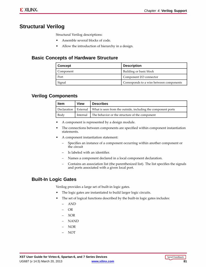
Chapter 4: Verilog Suppor t
Structural VerilogStructural Verilog descriptions:
• Assemble several blocks of code.
• Allow the introduction of hierarchy in a design.
Basic Concepts of Hardware StructureConcept DescriptionComponent Building or basic block
Port Component I/O connector
Signal Corresponds to a wire between components
Verilog ComponentsItem View DescribesDeclaration External What is seen from the outside, including the component ports
Body Internal The behavior or the structure of the component
• A component is represented by a design module.
• The connections between components are specified within component instantiationstatements.
• A component instantiation statement:
– Specifies an instance of a component occurring within another component orthe circuit
– Is labeled with an identifier.
– Names a component declared in a local component declaration.
– Contains an association list (the parenthesized list). The list specifies the signalsand ports associated with a given local port.
Built-In Logic GatesVerilog provides a large set of built-in logic gates.
• The logic gates are instantiated to build larger logic circuits.
• The set of logical functions described by the built-in logic gates includes:
– AND
– OR
– XOR
– NAND
– NOR
– NOT
XST User Guide for Vir tex-6, Spar tan-6, and 7 Series DevicesUG687 (v 14.5) March 20, 2013 www.xilinx.com 81
Send Feedback

Chapter 4: Verilog Suppor t
2-Input XOR Function Verilog Coding ExampleIn this coding example, each instance of the built-in modules has a unique instantiationname such as:
• a_inv
• b_inv
• out
module build_xor (a, b, c);input a, b;output c;wire c, a_not, b_not;
not a_inv (a_not, a);not b_inv (b_not, b);and a1 (x, a_not, b);and a2 (y, b_not, a);or out (c, x, y);
endmodule
Half-Ad der Verilog Coding ExampleThis coding example shows the structural description of a half-Adder composed of four,2-input nand modules.
module halfadd (X, Y, C, S);input X, Y;output C, S;wire S1, S2, S3;
nand NANDA(S3, X, Y);nand NANDB(S1, X, S3);nand NANDC(S2, S3, Y);nand NANDD(S, S1, S2);assign C = S3;
endmodule
Instantiating Pre-Defined Primitives• The structural features of Verilog allow you to design circuits by instantiating
pre-defined primitives such as:
– Gates
– Registers
– Xilinx® specific primitives such as CLKDLL and BUFG
• These primitives are:
– In addition to those included in Verilog
– Supplied with the XST Verilog libraries (unisim_comp.v ).
XST User Guide for Vir tex-6, Spar tan-6, and 7 Series Devices82 www.xilinx.com UG687 (v 14.5) March 20, 2013
Send Feedback

Chapter 4: Verilog Suppor t
Instantiating an FDC and a BUFG Primitive Verilog Coding ExampleThe unisim_comp.v library file includes the definitions for FDC and BUFG.
module example (sysclk, in, reset, out);input sysclk, in, reset;output out;reg out;wire sysclk_out;
FDC register (out, sysclk_out, reset, in); //position based referencingBUFG clk (.O(sysclk_out),.I(sysclk)); //name based referencing...
XST User Guide for Vir tex-6, Spar tan-6, and 7 Series DevicesUG687 (v 14.5) March 20, 2013 www.xilinx.com 83
Send Feedback

Chapter 4: Verilog Suppor t
Verilog Parameter sVerilog parameters.
• Allow you to create parameterized code that can be easily reused and scaled.
• Make code more readable, more compact, and easier to maintain.
• Describe such functionality as:
– Bus sizes
– The amount of certain repetitive elements in the modeled design unit
• Are constants.
For each instantiation of a parameterized module, default parameter values canbe overridden.
• Are the equivalent of VHDL generics.
Null string parameters are not supported.
Use the Generics command line option to redefine Verilog parameters defined in thetop-level design block. This allows you to modify the design without modifying thesource code. This feature is useful for IP core generation and flow testing.
Verilog Parameter s Coding ExampleIn this coding example, instantiation of the module lpm_reg with a instantiation widthof 8 causes the instance buf_373 to be 8 bits wide.
//// A Verilog parameter allows to control the width of an instantitated// block describing register logic//// Download: http://www.xilinx.com/txpatches/pub/documentation/misc/xstug_examples.zip// File: Verilog_Language_Support/parameter/parameter_1.v//module myreg (clk, clken, d, q);
parameter SIZE = 1;
input clk, clken;input [SIZE-1:0] d;output reg [SIZE-1:0] q;
always @(posedge clk)begin
if (clken)q <= d;
end
endmodule
module parameter_1 (clk, clken, di, do);
parameter SIZE = 8;
input clk, clken;input [SIZE-1:0] di;output [SIZE-1:0] do;
myreg #8 inst_reg (clk, clken, di, do);
endmodule
XST User Guide for Vir tex-6, Spar tan-6, and 7 Series Devices84 www.xilinx.com UG687 (v 14.5) March 20, 2013
Send Feedback
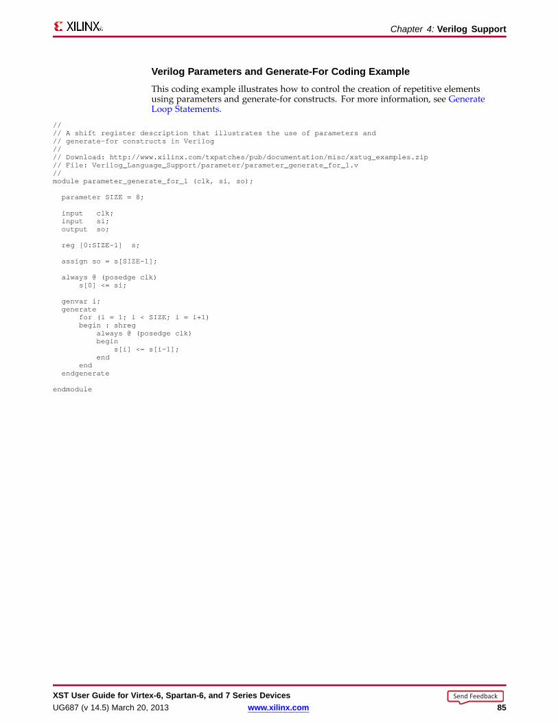
Chapter 4: Verilog Suppor t
Verilog Parameter s and Generate-For Coding ExampleThis coding example illustrates how to control the creation of repetitive elementsusing parameters and generate-for constructs. For more information, see GenerateLoop Statements.
//// A shift register description that illustrates the use of parameters and// generate-for constructs in Verilog//// Download: http://www.xilinx.com/txpatches/pub/documentation/misc/xstug_examples.zip// File: Verilog_Language_Support/parameter/parameter_generate_for_1.v//module parameter_generate_for_1 (clk, si, so);
parameter SIZE = 8;
input clk;input si;output so;
reg [0:SIZE-1] s;
assign so = s[SIZE-1];
always @ (posedge clk)s[0] <= si;
genvar i;generate
for (i = 1; i < SIZE; i = i+1)begin : shreg
always @ (posedge clk)begin
s[i] <= s[i-1];end
endendgenerate
endmodule
XST User Guide for Vir tex-6, Spar tan-6, and 7 Series DevicesUG687 (v 14.5) March 20, 2013 www.xilinx.com 85
Send Feedback
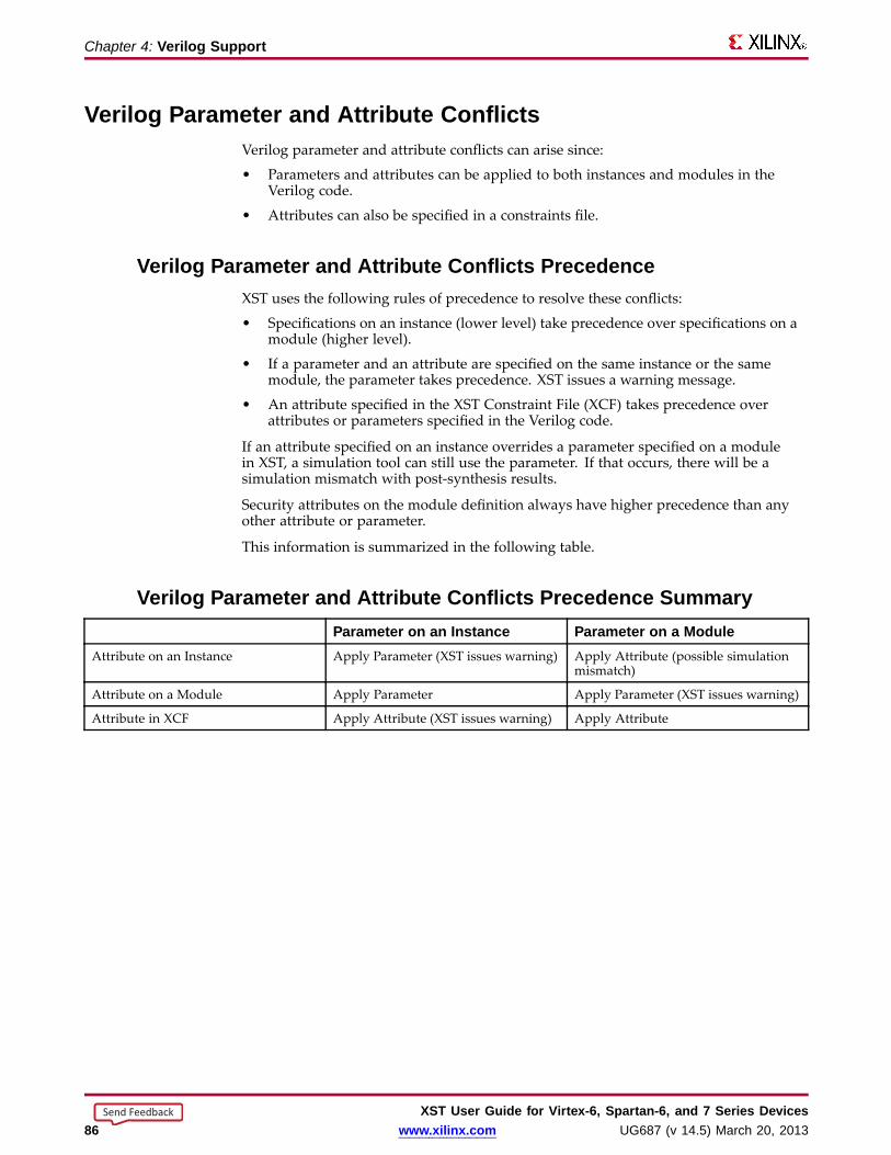
Chapter 4: Verilog Suppor t
Verilog Parameter and Attrib ute ConflictsVerilog parameter and attribute conflicts can arise since:
• Parameters and attributes can be applied to both instances and modules in theVerilog code.
• Attributes can also be specified in a constraints file.
Verilog Parameter and Attrib ute Conflicts PrecedenceXST uses the following rules of precedence to resolve these conflicts:
• Specifications on an instance (lower level) take precedence over specifications on amodule (higher level).
• If a parameter and an attribute are specified on the same instance or the samemodule, the parameter takes precedence. XST issues a warning message.
• An attribute specified in the XST Constraint File (XCF) takes precedence overattributes or parameters specified in the Verilog code.
If an attribute specified on an instance overrides a parameter specified on a modulein XST, a simulation tool can still use the parameter. If that occurs, there will be asimulation mismatch with post-synthesis results.
Security attributes on the module definition always have higher precedence than anyother attribute or parameter.
This information is summarized in the following table.
Verilog Parameter and Attrib ute Conflicts Precedence Summar yParameter on an Instance Parameter on a Module
Attribute on an Instance Apply Parameter (XST issues warning) Apply Attribute (possible simulationmismatch)
Attribute on a Module Apply Parameter Apply Parameter (XST issues warning)
Attribute in XCF Apply Attribute (XST issues warning) Apply Attribute
XST User Guide for Vir tex-6, Spar tan-6, and 7 Series Devices86 www.xilinx.com UG687 (v 14.5) March 20, 2013
Send Feedback

Chapter 4: Verilog Suppor t
Verilog Usage RestrictionsVerilog usage restrictions in XST include:
• Case Sensitivity• Blocking and Non-Blocking Assignments• Integer Handling
Case SensitivityXST supports Verilog case sensitivity despite the potential of name collision.• Since Verilog is case sensitive, the names of modules, instances, and signals can
theoretically be made unique by changing capitalization.– XST can synthesize a design in which instance and signal names differ only by
capitalization.– XST errors out when module names differ only by capitalization.
• Do not rely on capitalization alone to make object names unique. Capitalizationalone can:– Cause problems in mixed language projects.– Prevent you from applying constraints with an XST Constraint File (XCF) file to .
Bloc king and Non-Bloc king AssignmentsXST supports blocking and non-blocking assignments.• Do not mix blocking and non-blocking assignments.• Although XST synthesizes the design without error, mixing blocking and
non-blocking assignments can cause errors during simulation.
Unacceptab le Coding Example OneDo not mix blocking and non-blocking assignments to the same signal.
always @(in1)begin
if (in2)out1 = in1;
elseout1 <= in2;
end
Unacceptab le Coding Example TwoDo not mix blocking and non-blocking assignments for different bits of the same signal.
if (in2)begin
out1[0] = 1’b0;out1[1] <= in1;
endelsebegin
out1[0] = in2;out1[1] <= 1’b1;
end
XST User Guide for Vir tex-6, Spar tan-6, and 7 Series DevicesUG687 (v 14.5) March 20, 2013 www.xilinx.com 87
Send Feedback

Chapter 4: Verilog Suppor t
Integ er HandlingXST handles integers differently from other synthesis tools in some situations. In thoseinstances, the integers must be coded in a particular way.
Integ er Handling in Verilog Case StatementsUnsized integers in case item expressions can cause unpredictable results.
Integ er Handling in Verilog Case Statements Coding Example• In this coding example, the case item expression 4 is an unsized integer that causes
unpredictable results.
• To resolve this problem, size the case item expression 4 to 3 bits.
reg [2:0] condition1;always @(condition1)begincase(condition1)4 : data_out = 2; // < will generate bad logic3’d4 : data_out = 2; // < will workendcaseend
Integ er Handling in Verilog ConcatenationsUnsized integers in Verilog concatenations can cause unpredictable results.
If you use an expression that results in an unsized integer:
• Assign the expression to a temporary signal.
• Use the temporary signal in the concatenation.
reg [31:0] temp;assign temp = 4’b1111 % 2;assign dout = {12/3,temp,din};
XST User Guide for Vir tex-6, Spar tan-6, and 7 Series Devices88 www.xilinx.com UG687 (v 14.5) March 20, 2013
Send Feedback
Chapter 4: Verilog Suppor t
Verilog–2001 Attrib utes and Meta CommentsVerilog–2001 attributes and meta comments include:
• Verilog-2001 Attributes
• Verilog Meta Comments
Verilog-2001 Attrib utes• Verilog-2001 attributes pass specific information to programs such as synthesis tools.
• Verilog-2001 attributes are generally accepted.
• You can specify Verilog-2001 attributes anywhere for 1) operators or signals, 2)within module declarations and instantiations.
• Although the compiler may support other attribute declarations, XST ignores them.
• Use Verilog-2001 attributes to:
– Set constraints on individual objects, such as:
♦ Module
♦ Instance
♦ Net
– Set the following synthesis constraints:
♦ Full Case
♦ Parallel Case
Verilog Meta Comments• Verilog meta comments are understood by the Verilog parser.
• Verilog meta comments set constraints on individual objects, such as:
– Module
– Instance
– Net
• Verilog meta comments set directives on synthesis:
– parallel_case and full_case
– translate_on and translate_off
– All tool specific directives (for example, syn_sharing)
For more information, see Chapter 9, Design Constraints.
XST User Guide for Vir tex-6, Spar tan-6, and 7 Series DevicesUG687 (v 14.5) March 20, 2013 www.xilinx.com 89
Send Feedback
Chapter 4: Verilog Suppor t
Verilog Meta Comment Suppor tXST supports:
• C-style and Verilog style meta comments
– C-style
/* ... */
C-style comments can be multiple line.
– Verilog style
// ...
Verilog style comments end at the end of the line.
• Translate Off and Translate On
// synthesis translate_on// synthesis translate_off
• Parallel Case
// synthesis parallel_case full_case// synthesis parallel_case// synthesis full_case
• Constraints on individual objects
Verilog Meta Comment Syntax// synthesis attribute [of] ObjectName [is] AttributeValue
Verilog Meta Comment Syntax Examples// synthesis attribute RLOC of u123 is R11C1.S0
// synthesis attribute HUSET u1 MY_SET
// synthesis attribute fsm_extract of State2 is "yes"
// synthesis attribute fsm_encoding of State2 is "gray"
XST User Guide for Vir tex-6, Spar tan-6, and 7 Series Devices90 www.xilinx.com UG687 (v 14.5) March 20, 2013
Send Feedback

Chapter 4: Verilog Suppor t
Verilog ConstructsVerilog constructs include:
• Verilog Constants
• Verilog Data Types
• Verilog Continuous Assignments
• Verilog Procedural Assignments
• Verilog Design Hierarchies
• Verilog Compiler Directives
Verilog ConstantsConstant StatusInteger Supported
Real Supported
Strings Unsupported
Verilog Data TypesData Type Categor y StatusNet types • tri0
• tri1
• trireg
Unsupported
Drive strengths All Ignored
Registers Real and realtime registers Unsupported
Named events All Unsupported
Verilog Contin uous AssignmentsContin uous Assignment StatusDrive Strength Ignored
Delay Ignored
XST User Guide for Vir tex-6, Spar tan-6, and 7 Series DevicesUG687 (v 14.5) March 20, 2013 www.xilinx.com 91
Send Feedback
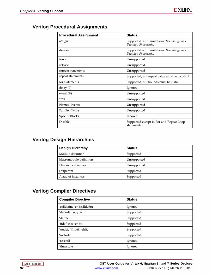
Chapter 4: Verilog Suppor t
Verilog Procedural AssignmentsProcedural Assignment Statusassign Supported with limitations. See Assign and
Deassign Statements.
deassign Supported with limitations. See Assign andDeassign Statements.
force Unsupported
release Unsupported
forever statements Unsupported
repeat statements Supported, but repeat value must be constant
for statements Supported, but bounds must be static
delay (#) Ignored
event (@) Unsupported
wait Unsupported
Named Events Unsupported
Parallel Blocks Unsupported
Specify Blocks Ignored
Disable Supported except in For and Repeat Loopstatements.
Verilog Design Hierar chiesDesign Hierar chy StatusModule definition Supported
Macromodule definition Unsupported
Hierarchical names Unsupported
Defparam Supported
Array of instances Supported
Verilog Compiler DirectivesCompiler Directive Status
‘celldefine ‘endcelldefine Ignored
‘default_nettype Supported
‘define Supported
‘ifdef ‘else ‘endif Supported
‘undef, ‘ifndef, ‘elsif, Supported
‘include Supported
‘resetall Ignored
‘timescale Ignored
XST User Guide for Vir tex-6, Spar tan-6, and 7 Series Devices92 www.xilinx.com UG687 (v 14.5) March 20, 2013
Send Feedback
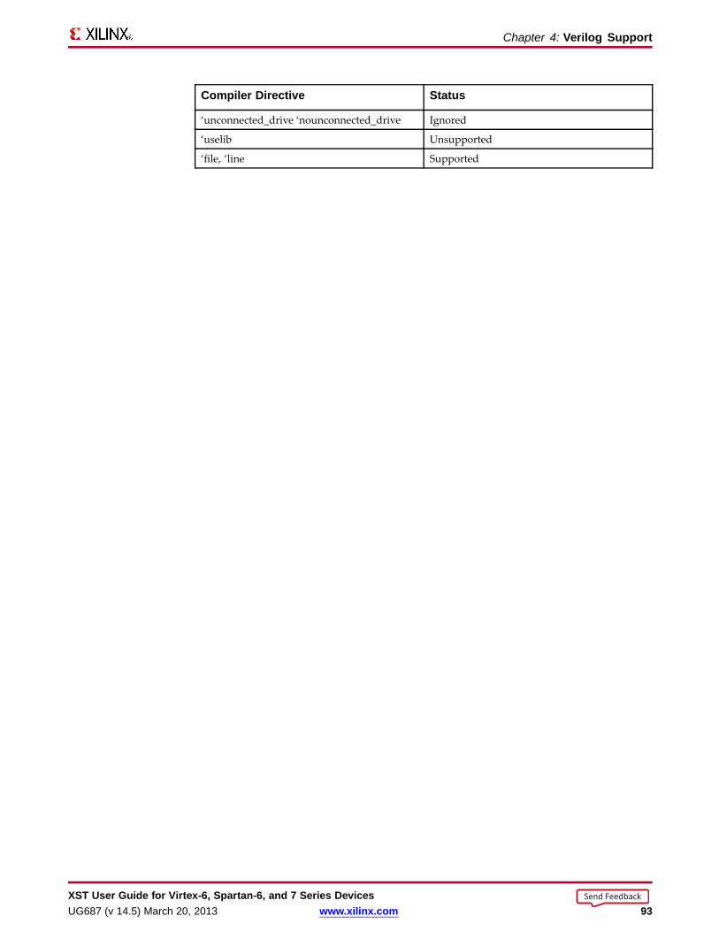
Chapter 4: Verilog Suppor t
Compiler Directive Status
‘unconnected_drive ‘nounconnected_drive Ignored
‘uselib Unsupported
‘file, ‘line Supported
XST User Guide for Vir tex-6, Spar tan-6, and 7 Series DevicesUG687 (v 14.5) March 20, 2013 www.xilinx.com 93
Send Feedback

Chapter 4: Verilog Suppor t
Verilog System Tasks and FunctionsXST supports system tasks or function as shown in the following table. XST ignoresunsupported system tasks.
System Task or Function Status Comment$display Supported Escape sequences are limited to %d,
%b, %h, %o, %c and %s
$fclose Supported
$fdisplay Ignored
$fgets Supported
$finish Supported $finish is supported for statically neveractive conditional branches only
$fopen Supported
$fscanf Supported Escape sequences are limited to %band %d
$fwrite Ignored
$monitor Ignored
$random Ignored
$readmemb Supported
$readmemh Supported
$signed Supported
$stop Ignored
$strobe Ignored
$time Ignored
$unsigned Supported
$write Supported Escape sequences are limited to %d,%b, %h, %o, %c and %s
all others Ignored
XST User Guide for Vir tex-6, Spar tan-6, and 7 Series Devices94 www.xilinx.com UG687 (v 14.5) March 20, 2013
Send Feedback

Chapter 4: Verilog Suppor t
Using Conversion FunctionsUse the following syntax to call $signed and $unsigned system tasks on any expression.
$signed(expr) or $unsigned(expr)
• The return value from these calls is the same size as the input value.• The sign of the return value is forced regardless of any previous sign.
Loading Memor y Contents With File I/O TasksUse the $readmemb and $readmemh system tasks to initialize block memories.• Use $readmemb for binary representation.• Use $readmemh for hexadecimal representation.• Use index parameters to avoid behavioral conflicts between XST and the simulator.
$readmemb("rams_20c.data",ram, 0, 7);
• For more information, see Specifying RAM Initial Contents in an External Data File.
Displa y TasksUse display tasks to:• Print information to the console.• Write information to an external file.
You must call these tasks from within initial blocks.
Suppor ted Escape Sequences• %h• %d• %o• %b• %c• %s
Verilog Syntax ExampleThe syntax for reporting the value of a binary constant in decimal is:
parameter c = 8’b00101010;
initialbegin$display ("The value of c is %d", c);end
Verilog Log File ExampleXST writes the following to the log file during HDL Analysis:
Analyzing top module <example>.c = 8’b00101010"foo.v" line 9: $display : The value of c is 42
XST User Guide for Vir tex-6, Spar tan-6, and 7 Series DevicesUG687 (v 14.5) March 20, 2013 www.xilinx.com 95
Send Feedback
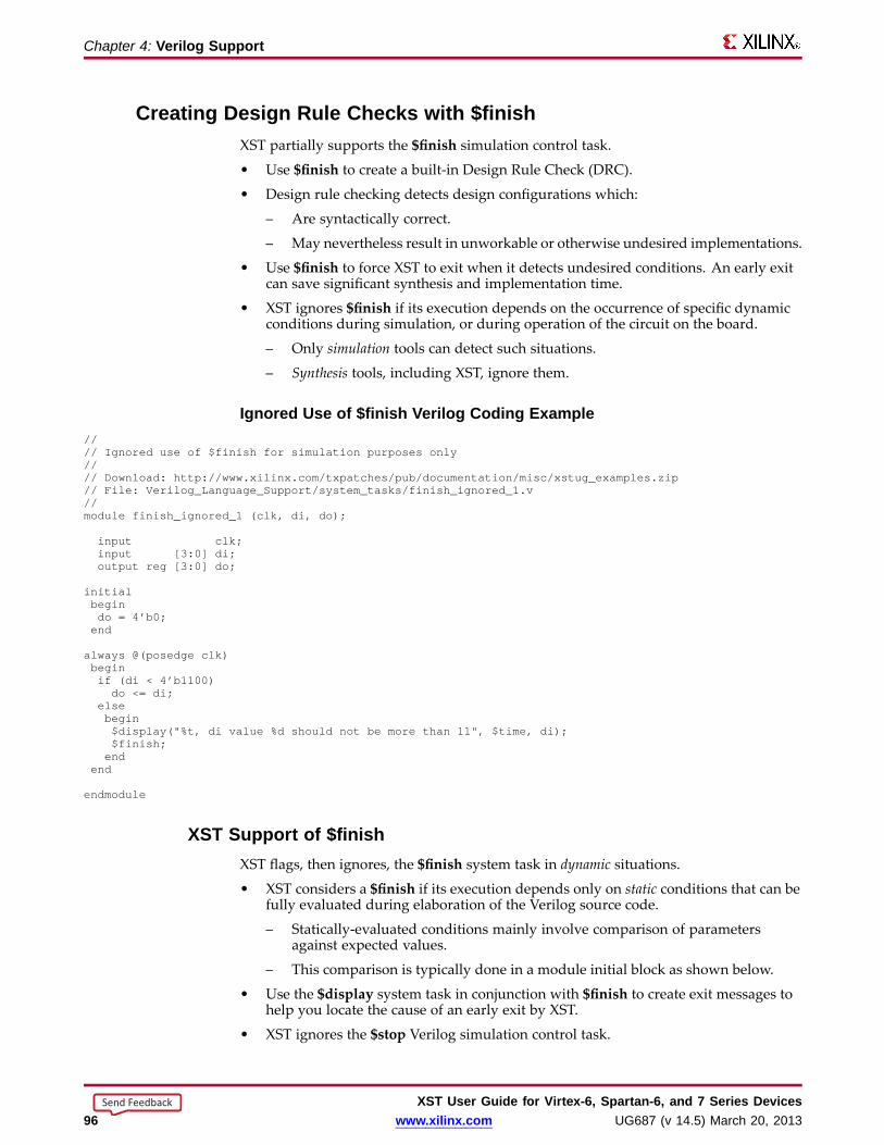
Chapter 4: Verilog Suppor t
Creating Design Rule Checks with $finishXST partially supports the $finish simulation control task.
• Use $finish to create a built-in Design Rule Check (DRC).
• Design rule checking detects design configurations which:
– Are syntactically correct.
– May nevertheless result in unworkable or otherwise undesired implementations.
• Use $finish to force XST to exit when it detects undesired conditions. An early exitcan save significant synthesis and implementation time.
• XST ignores $finish if its execution depends on the occurrence of specific dynamicconditions during simulation, or during operation of the circuit on the board.
– Only simulation tools can detect such situations.
– Synthesis tools, including XST, ignore them.
Ignored Use of $finish Verilog Coding Example//// Ignored use of $finish for simulation purposes only//// Download: http://www.xilinx.com/txpatches/pub/documentation/misc/xstug_examples.zip// File: Verilog_Language_Support/system_tasks/finish_ignored_1.v//module finish_ignored_1 (clk, di, do);
input clk;input [3:0] di;output reg [3:0] do;
initialbegindo = 4’b0;end
always @(posedge clk)beginif (di < 4’b1100)do <= di;
elsebegin$display("%t, di value %d should not be more than 11", $time, di);$finish;end
end
endmodule
XST Suppor t of $finishXST flags, then ignores, the $finish system task in dynamic situations.
• XST considers a $finish if its execution depends only on static conditions that can befully evaluated during elaboration of the Verilog source code.
– Statically-evaluated conditions mainly involve comparison of parametersagainst expected values.
– This comparison is typically done in a module initial block as shown below.
• Use the $display system task in conjunction with $finish to create exit messages tohelp you locate the cause of an early exit by XST.
• XST ignores the $stop Verilog simulation control task.
XST User Guide for Vir tex-6, Spar tan-6, and 7 Series Devices96 www.xilinx.com UG687 (v 14.5) March 20, 2013
Send Feedback

Chapter 4: Verilog Suppor t
Suppor ted Use of $finish for Design Rule Checking Verilog CodingExample
//// Supported use of $finish for design rule checking//// Download: http://www.xilinx.com/txpatches/pub/documentation/misc/xstug_examples.zip// File: Verilog_Language_Support/system_tasks/finish_supported_1.v//module finish_supported_1 (clk, di, do);
parameter integer WIDTH = 4;parameter DEVICE = "virtex6";
input clk;input [WIDTH-1:0] di;output reg [WIDTH-1:0] do;
initialbeginif (DEVICE != "virtex6")begin$display ("DRC ERROR: Unsupported device family: %s.", DEVICE);$finish;endif (WIDTH < 8)begin$display ("DRC ERROR: This module not tested for data width: %d. Minimum allowed width is 8.", WIDTH);$finish;end
end
always @(posedge clk)begindo <= di;end
endmodule
XST User Guide for Vir tex-6, Spar tan-6, and 7 Series DevicesUG687 (v 14.5) March 20, 2013 www.xilinx.com 97
Send Feedback

Chapter 4: Verilog Suppor t
Verilog PrimitivesXST supports Verilog gate-level primitives except as shown in the table below.
XST does not support Verilog switch-level primitives, such as:
• cmos, nmos, pmos, rcmos, rnmos, rpmos
• rtran, rtranif0, rtranif1, tran, tranif0, tranif1
Verilog Gate Level Primitives Not Suppor ted in XSTPrimitive Status
Pulldown and pullup Unsupported
Drive strength and delay Ignored
Arrays of primitives Unsupported
Gate-Level Primitive Syntaxgate_type instance_name (output, inputs,...);
Gate-Level Primitive Coding Exampleand U1 (out, in1, in2); bufif1 U2 (triout, data, trienable);
Verilog User Defined Primitive (UDP)The Verilog User Defined Primitive (UDP) provides a modeling technique for describingfunctionality in the form of a state table.
• The state table:
– Enumerates all combinations of input values.
– Specifies the corresponding values on the circuit’s unique output.
• The functionality modeled with a UDP is:
– Combinatorial, or
– Sequential
• A UDP is a convenient technique for modeling low-complexity functionality, such as:
– Simple combinatorial functions, or
– Basic sequential elements
• For more elaborate circuit descriptions:
– Use Behavioral Verilog modeling techniques.
– Leverage the inference capabilities of XST.
• For more information about inference capabilities and coding guidelines in Verilogand VHDL, see Chapter 7, HDL Coding Techniques.
• For more information about the Verilog User Defined Primitive (UDP), includingsyntax rules, see your Verilog Language Reference manual.
XST User Guide for Vir tex-6, Spar tan-6, and 7 Series Devices98 www.xilinx.com UG687 (v 14.5) March 20, 2013
Send Feedback

Chapter 4: Verilog Suppor t
UDP Definition and Instantiation• A UDP must be defined before it can be instantiated.
• A UDP definition:
– Is described between the primitive and endprimitive keywords.
– May be found anywhere outside the scope of anymodule-endmodule section.
• A UDP is instantiated the same as gate-level primitives and user-defined modules.
Combinatorial UDPA combinatorial UDP uses the value of its inputs to determine the next value of itsoutput. This allows it to describe any combinatorial function.
Combinatorial UDP Coding Example//// Description and instantiation of a user defined primitive// combinatorial function//// Download: http://www.xilinx.com/txpatches/pub/documentation/misc/xstug_examples.zip// File: Verilog_Language_Support/user_defined_primitives/udp_combinatorial_1.v//primitive myand2 (o, a, b);input a, b;output o;
table// a b : o0 0 : 0;0 1 : 0;1 0 : 0;1 1 : 1;
endtable
endprimitive
module udp_combinatorial_1 (a, b, c, o);input a, b, c;output o;
wire s;
myand2 i1 (.a(a), .b(b), .o(s));myand2 i2 (.a(s), .b(c), .o(o));
endmodule
Sequential UDPA sequential UDP uses 1) the value of its inputs and 2) the current value of its output,to determine the next value of its output.
• A sequential UDP is able to:
– Model both level-sensitive and edge-sensitive behavior.
– Describe such sequential elements as flip-flops and latches.
• An initial value may be specified.
XST User Guide for Vir tex-6, Spar tan-6, and 7 Series DevicesUG687 (v 14.5) March 20, 2013 www.xilinx.com 99
Send Feedback

Chapter 4: Verilog Suppor t
Sequential UDP Coding Example//// Description and instantiation of a user defined primitive// Sequential function//// Download: http://www.xilinx.com/txpatches/pub/documentation/misc/xstug_examples.zip// File: Verilog_Language_Support/user_defined_primitives/udp_sequential_2.v//primitive mydff (q, d, c);input c, d;output reg q;
initial q = 1’b0;
table// c d : q : q+
r 0 : ? : 0;r 1 : ? : 1;f ? : ? : -;? * : ? : -;
endtable
endprimitive
module udp_sequential_2 (clk, si, so);input clk, si;output so;
wire s1, s2;
mydff i1 (.c(clk), .d(si), .q(s1));mydff i2 (.c(clk), .d(s1), .q(s2));mydff i3 (.c(clk), .d(s2), .q(so));
endmodule
XST User Guide for Vir tex-6, Spar tan-6, and 7 Series Devices100 www.xilinx.com UG687 (v 14.5) March 20, 2013
Send Feedback

Chapter 4: Verilog Suppor t
Verilog Reserved KeywordsKeywords marked with an asterisk (*) are reserved by Verilog, but XST does not supportthem.
always and assign automatic
begin buf bufif0 bufif1case casex casez cell*cmos config* deassign default
defparam design* disable edge
else end endcase endconfig*
endfunction endgenerate endmodule endprimitive
endspecify endtable endtask event
for force forever fork
function generate genvar highz0
highz1 if ifnone incdir*
include* initial inout input
instance* integer join large
liblist* library* localparam macromodule
medium module nand negedgenmos nor noshow-cancelled* not
notif0 notif1 or output
parameter pmos posedge primitive
pull0 pull1 pullup pulldown
pulsestyle- _ondetect* pulsestyle- _onevent* rcmos real
realtime reg release repeat
rnmos rpmos rtran rtranif0
rtranif1 scalared show-cancelled* signed
small specify specparam strong0
strong1 supply0 supply1 table
task time tran tranif0
tranif1 tri tri0 tri1
triand trior trireg use*
vectored wait wand weak0
weak1 while wire wor
xnor xor
XST User Guide for Vir tex-6, Spar tan-6, and 7 Series DevicesUG687 (v 14.5) March 20, 2013 www.xilinx.com 101
Send Feedback

XST User Guide for Vir tex-6, Spar tan-6, and 7 Series Devices102 www.xilinx.com UG687 (v 14.5) March 20, 2013
Send Feedback

Chapter 5
Behavioral VerilogXST supports the Behavioral Verilog Hardware Description Language (HDL), exceptas otherwise noted.
Variab les in Behavioral Verilog• Variables in Behavioral Verilog are declared as:
– integer– real
• These declarations are used in test code only. Verilog provides data types such asreg and wire for actual hardware description.
• The difference between reg and wire depends on whether the variable is given itsvalue in 1) a procedural block (reg) or 2) in a continuous assignment (wire).– Both reg and wire have a default width of one bit (scalar).– To specify an N-bit width (vectors) for a declared reg or wire, the left and right
bit positions are defined in square brackets separated by a colon.– In Verilog-2001, reg and wire data types can be signed or unsigned.
Variab le Declarations Coding Examplereg [3:0] arb_priority;wire [31:0] arb_request;wire signed [8:0] arb_signed;
Initial ValuesYou can initialize Registers in Verilog-2001 when you declare them.• The initial value:
– Is a constant.– Cannot depend on earlier initial values.– Cannot be a function or task call.– Can be a parameter value propagated to the Register.– Specifies all bits of a vector.
• When you assign a Register an initial value in a declaration, XST sets this value onthe output of the Register at global reset or power up.
• When a value is assigned in this manner:– The value is carried in the NGC file as an INIT attribute on the Register.– The value is independent of any local reset.
XST User Guide for Vir tex-6, Spar tan-6, and 7 Series DevicesUG687 (v 14.5) March 20, 2013 www.xilinx.com 103
Send Feedback

Chapter 5: Behavioral Verilog
Assigning an Initial Value to a RegisterYou can assign a set/reset (initial) value to a Register.• Assign the value to the Register when the Register reset line goes to the appropriate
value. See the following coding example.• When you assign the initial value to a variable:
– The value is implemented as a Flip-Flop, the output of which is controlled bya local reset.
– The value is carried in the NGC file as an FDP or FDC Flip-Flop.
Initial Values Coding Example Onereg arb_onebit = 1’b0;reg [3:0] arb_priority = 4’b1011;
Initial Values Coding Example Twoalways @(posedge clk)begin
if (rst)arb_onebit <= 1’b0;
end
Arrays of Reg and WireVerilog allows arrays of reg and wire.
Arrays Coding Example OneThis coding example describes an array of 32 elements. Each element is 4-bits wide.
reg [3:0] mem_array [31:0];
Arrays Coding Example TwoThis coding example describes an array of 64 8-bit wide elements. These elements can beassigned only in structural Verilog code.
wire [7:0] mem_array [63:0];
Multi-Dimensional Arra ysXST supports multi-dimensional array types of up to two dimensions.• Multi-dimensional arrays can be:
– Any net– Any variable data type
• You can code assignments and arithmetic operations with arrays.• You cannot select more than one element of an array at one time.• You cannot pass multi-dimensional arrays to:
– System tasks or functions– Regular tasks or functions
Multi-Dimensional Arra y Verilog Coding Example OneThis coding example describes an array of 256 x 16 wire elements of 8-bits each. Theseelements can be assigned only in structural Verilog code.
wire [7:0] array2 [0:255][0:15];
XST User Guide for Vir tex-6, Spar tan-6, and 7 Series Devices104 www.xilinx.com UG687 (v 14.5) March 20, 2013
Send Feedback

Chapter 5: Behavioral Verilog
Multi-Dimensional Arra y Verilog Coding Example TwoThis coding example describes an array of 256 x 8 register elements, each 64 bits wide.These elements can be assigned in Behavioral Verilog code.
reg [63:0] regarray2 [255:0][7:0];
Data TypesThe Verilog representation of the bit data type contains the following values:
• 0
logic zero
• 1
logic one
• x
unknown logic value
• z
high impedance
XST-Suppor ted Verilog Data Types• net
• wire
• tri
• triand/wand
• trior/wor
• registers
• reg
• integer
• supply nets
• supply0
• supply1
• constants
• parameter
• Multi-dimensional arrays (memories)
Net and Register sNet and Registers can be either:
• Single bit (scalar)
• Multiple bit (vectors)
XST User Guide for Vir tex-6, Spar tan-6, and 7 Series DevicesUG687 (v 14.5) March 20, 2013 www.xilinx.com 105
Send Feedback
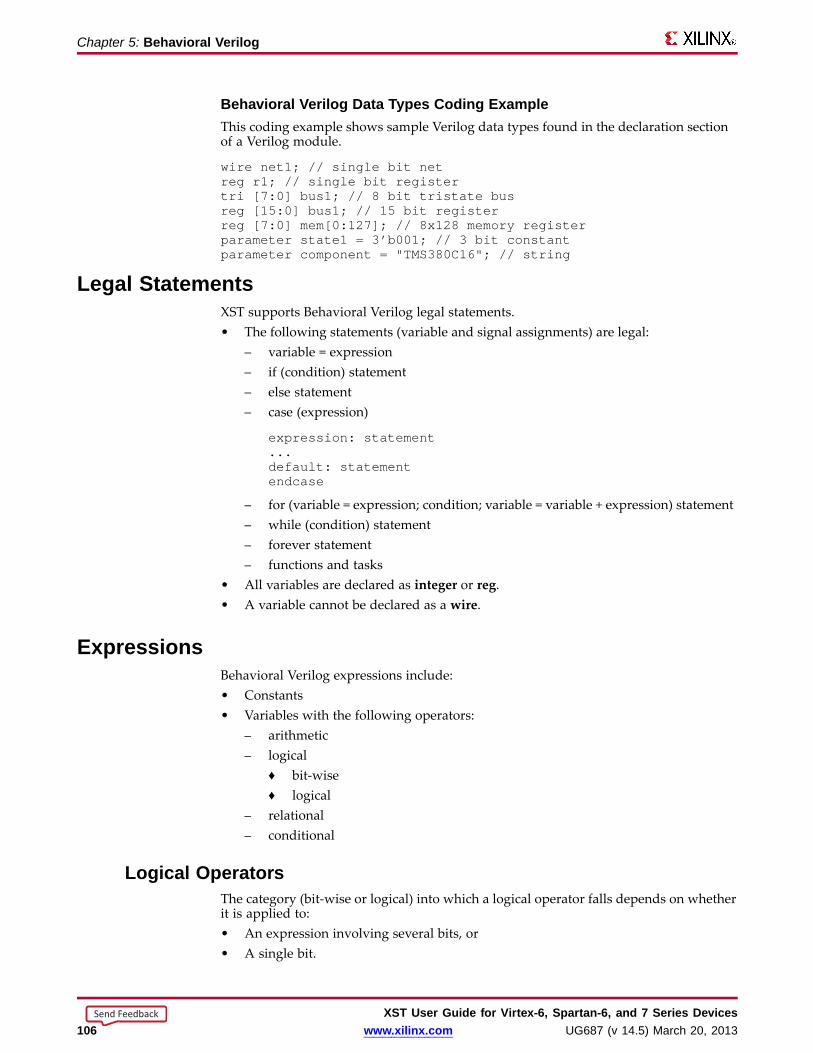
Chapter 5: Behavioral Verilog
Behavioral Verilog Data Types Coding ExampleThis coding example shows sample Verilog data types found in the declaration sectionof a Verilog module.
wire net1; // single bit netreg r1; // single bit registertri [7:0] bus1; // 8 bit tristate busreg [15:0] bus1; // 15 bit registerreg [7:0] mem[0:127]; // 8x128 memory registerparameter state1 = 3’b001; // 3 bit constantparameter component = "TMS380C16"; // string
Legal StatementsXST supports Behavioral Verilog legal statements.• The following statements (variable and signal assignments) are legal:
– variable = expression– if (condition) statement– else statement– case (expression)
expression: statement...default: statementendcase
– for (variable = expression; condition; variable = variable + expression) statement– while (condition) statement– forever statement– functions and tasks
• All variables are declared as integer or reg.• A variable cannot be declared as a wire.
ExpressionsBehavioral Verilog expressions include:• Constants• Variables with the following operators:
– arithmetic– logical
♦ bit-wise♦ logical
– relational– conditional
Logical Operator sThe category (bit-wise or logical) into which a logical operator falls depends on whetherit is applied to:• An expression involving several bits, or• A single bit.
XST User Guide for Vir tex-6, Spar tan-6, and 7 Series Devices106 www.xilinx.com UG687 (v 14.5) March 20, 2013
Send Feedback

Chapter 5: Behavioral Verilog
Suppor ted Operator sArithmetic Logical Relational Conditional
+ & < ?- && ==
* | ===
** || <=
/ ^ >=
% ~ >=
~^ !=
^~ !==<< >>><<<>>>
Suppor ted ExpressionsExpression Symbol Status
Concatenation {} Supported
Replication {{}} Supported
Arithmetic +, -, *,** Supported
Division / Supported only if:
• Second operand is a power of 2.
OR
• Both operands are constant.
Modulus % Supported only if second operand is apower of 2
Addition + Supported
Subtraction - Supported
Multiplication * Supported
Power ** Supported
• Both operands are constants,with the second operand beingnon-negative.
• If the first operand is a 2, then thesecond operand can be a variable.
• XST does not support the realdata type. Any combination ofoperands that results in a real typecauses an error.
• The values X (unknown) and Z(high impedance) are not allowed.
Relational >, <, >=, <= Supported
XST User Guide for Vir tex-6, Spar tan-6, and 7 Series DevicesUG687 (v 14.5) March 20, 2013 www.xilinx.com 107
Send Feedback
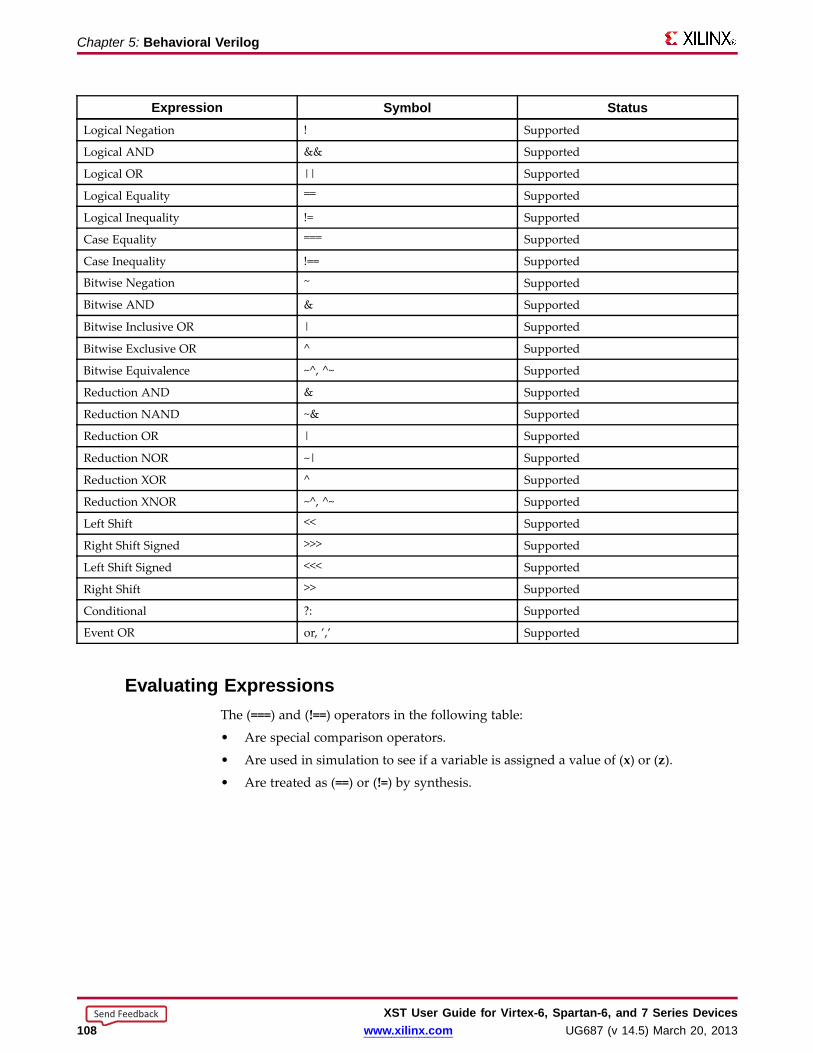
Chapter 5: Behavioral Verilog
Expression Symbol StatusLogical Negation ! Supported
Logical AND && Supported
Logical OR || Supported
Logical Equality == Supported
Logical Inequality != Supported
Case Equality === Supported
Case Inequality !== Supported
Bitwise Negation ~ Supported
Bitwise AND & Supported
Bitwise Inclusive OR | Supported
Bitwise Exclusive OR ^ Supported
Bitwise Equivalence ~^, ^~ Supported
Reduction AND & Supported
Reduction NAND ~& Supported
Reduction OR | Supported
Reduction NOR ~| Supported
Reduction XOR ^ Supported
Reduction XNOR ~^, ^~ Supported
Left Shift << Supported
Right Shift Signed >>> Supported
Left Shift Signed <<< Supported
Right Shift >> Supported
Conditional ?: Supported
Event OR or, ’,’ Supported
Evaluating ExpressionsThe (===) and (!==) operators in the following table:
• Are special comparison operators.
• Are used in simulation to see if a variable is assigned a value of (x) or (z).
• Are treated as (==) or (!=) by synthesis.
XST User Guide for Vir tex-6, Spar tan-6, and 7 Series Devices108 www.xilinx.com UG687 (v 14.5) March 20, 2013
Send Feedback

Chapter 5: Behavioral Verilog
Evaluated Expressions Based On Most Frequentl y Used Operator sa b a==b a===b a!=b a!==b a&b a&&b a|b a||b a^b0 0 1 1 0 0 0 0 0 0 0
0 1 0 0 1 1 0 0 1 1 1
0 x x 0 x 1 0 0 x x x
0 z x 0 x 1 0 0 x x x
1 0 0 0 1 1 0 0 1 1 1
1 1 1 1 0 0 1 1 1 1 0
1 x x 0 x 1 x x 1 1 x
1 z x 0 x 1 x x 1 1 x
x 0 x 0 x 1 0 0 x x x
x 1 x 0 x 1 x x 1 1 x
x x x 1 x 0 x x x x x
x z x 0 x 1 x x x x x
z 0 x 0 x 1 0 0 x x x
z 1 x 0 x 1 x x 1 1 x
z x x 0 x 1 x x x x x
z z x 1 x 0 x x x x x
Bloc ksXST supports some block statements.
• Block statements:
– Group statements together.
– Are designated by begin and end keywords.
– Execute the statements in the order listed within the block.
• XST supports sequential blocks only.
• XST does not support parallel blocks.
• All procedural statements occur in blocks that are defined inside modules.
• The two kinds of procedural blocks are:
– initial block
– always block
• Verilog uses begin and end keywords within each block to enclose the statements.Since initial blocks are ignored during synthesis, only always blocks are discussed.
• always blocks usually take the following format. Each statement is a proceduralassignment line terminated by a semicolon.
alwaysbeginstatement....end
XST User Guide for Vir tex-6, Spar tan-6, and 7 Series DevicesUG687 (v 14.5) March 20, 2013 www.xilinx.com 109
Send Feedback
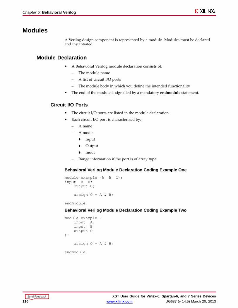
Chapter 5: Behavioral Verilog
ModulesA Verilog design component is represented by a module. Modules must be declaredand instantiated.
Module Declaration• A Behavioral Verilog module declaration consists of:
– The module name
– A list of circuit I/O ports
– The module body in which you define the intended functionality
• The end of the module is signalled by a mandatory endmodule statement.
Circuit I/O Por ts• The circuit I/O ports are listed in the module declaration.
• Each circuit I/O port is characterized by:
– A name
– A mode:
♦ Input
♦ Output
♦ Inout
– Range information if the port is of array type.
Behavioral Verilog Module Declaration Coding Example Onemodule example (A, B, O);input A, B;
output O;
assign O = A & B;
endmodule
Behavioral Verilog Module Declaration Coding Example Twomodule example (
input A,input Boutput O
):
assign O = A & B;
endmodule
XST User Guide for Vir tex-6, Spar tan-6, and 7 Series Devices110 www.xilinx.com UG687 (v 14.5) March 20, 2013
Send Feedback

Chapter 5: Behavioral Verilog
Module Instantiation• A Behavioral Verilog module instantiation statement:
– Defines an instance name.
– Contains a port association list.
♦ The port association list specifies how the instance is connected in theparent module.
♦ Each element of the port association list ties a formal port of the moduledeclaration to an actual net of the parent module.
• A Behavioral Verilog module is instantiated in another module. See the followingcoding example.
Behavioral Verilog Module Instantiation Coding Examplemodule top (A, B, C, O);
input A, B, C;output O;wire tmp;
example inst_example (.A(A), .B(B), .O(tmp));
assign O = tmp | C;
endmodule
Contin uous AssignmentsXST supports both explicit and implicit continuous assignments.
• Continuous assignments model combinatorial logic in a concise way.
• XST ignores delays and strengths given to a continuous assignment.
• Continuous assignments are allowed on wire and tri data types only.
Explicit Contin uous AssignmentsExplicit continuous assignments start with an assign keyword after the net has beenseparately declared.
wire mysignal;...assign mysignal = select ? b : a;
Implicit Contin uous AssignmentsImplicit continuous assignments combine declaration and assignment.
wire misignal = a | b;
XST User Guide for Vir tex-6, Spar tan-6, and 7 Series DevicesUG687 (v 14.5) March 20, 2013 www.xilinx.com 111
Send Feedback
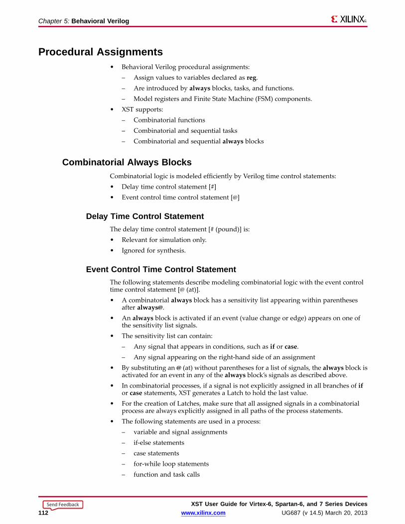
Chapter 5: Behavioral Verilog
Procedural Assignments• Behavioral Verilog procedural assignments:
– Assign values to variables declared as reg.– Are introduced by always blocks, tasks, and functions.– Model registers and Finite State Machine (FSM) components.
• XST supports:– Combinatorial functions– Combinatorial and sequential tasks– Combinatorial and sequential always blocks
Combinatorial Always Bloc ksCombinatorial logic is modeled efficiently by Verilog time control statements:• Delay time control statement [#]• Event control time control statement [@]
Delay Time Contr ol StatementThe delay time control statement [# (pound)] is:• Relevant for simulation only.• Ignored for synthesis.
Event Contr ol Time Contr ol StatementThe following statements describe modeling combinatorial logic with the event controltime control statement [@ (at)].• A combinatorial always block has a sensitivity list appearing within parentheses
after always@.• An always block is activated if an event (value change or edge) appears on one of
the sensitivity list signals.• The sensitivity list can contain:
– Any signal that appears in conditions, such as if or case.– Any signal appearing on the right-hand side of an assignment
• By substituting an @ (at) without parentheses for a list of signals, the always block isactivated for an event in any of the always block’s signals as described above.
• In combinatorial processes, if a signal is not explicitly assigned in all branches of ifor case statements, XST generates a Latch to hold the last value.
• For the creation of Latches, make sure that all assigned signals in a combinatorialprocess are always explicitly assigned in all paths of the process statements.
• The following statements are used in a process:– variable and signal assignments– if-else statements– case statements– for-while loop statements– function and task calls
XST User Guide for Vir tex-6, Spar tan-6, and 7 Series Devices112 www.xilinx.com UG687 (v 14.5) March 20, 2013
Send Feedback

Chapter 5: Behavioral Verilog
If-Else StatementsXST supports if-else statements.
• If-else statements use true-false conditions to execute statements.
– If the expression evaluates to true, the first statement is executed.
– If the expression evaluates to false, x, or z, the else statement is executed.
• A block of multiple statements is executed using begin and end keywords.
• If-else statements can be nested.
If-Else Statement Coding ExampleThis coding example uses an if-else statement to describe a Multiplexer.
module mux4 (sel, a, b, c, d, outmux);input [1:0] sel;input [1:0] a, b, c, d;output [1:0] outmux;reg [1:0] outmux;
always @(sel or a or b or c or d)begin
if (sel[1])if (sel[0])
outmux = d;else
outmux = c;else
if (sel[0])outmux = b;
elseoutmux = a;
end
endmodule
Case StatementsXST supports case statements.
• A case statement performs a comparison to an expression to evaluate one of severalparallel branches.
– The case statement evaluates the branches in the order they are written.
– The first branch that evaluates to true is executed.
– If none of the branches matches, the default branch is executed.
• Do not use unsized integers in case statements. Always size integers to a specificnumber of bits. Otherwise, results can be unpredictable.
• Casez treats all z values in any bit position of the branch alternative as a don’t care.
• Casex treats all x and z values in any bit position of the branch alternative as adon’t care.
• The question mark (?) can be used as a don’t care in either the casez or casex casestatements
XST User Guide for Vir tex-6, Spar tan-6, and 7 Series DevicesUG687 (v 14.5) March 20, 2013 www.xilinx.com 113
Send Feedback

Chapter 5: Behavioral Verilog
Describing a Multiple xer Case Statement Coding Examplemodule mux4 (sel, a, b, c, d, outmux);
input [1:0] sel;input [1:0] a, b, c, d;output [1:0] outmux;reg [1:0] outmux;
always @(sel or a or b or c or d)begin
case (sel)2’b00: outmux = a;2’b01: outmux = b;2’b10: outmux = c;default: outmux = d;
endcaseend
endmodule
Avoiding Priority Processing• The case statement in the above coding example evaluates the values of input sel
in priority order.• To avoid priority processing:
– Use a parallel-case Verilog attribute to ensure parallel evaluation of the selinputs.
– Replace the above case statement with:
(* parallel_case *) case(sel)
For and Repeat StatementsXST supports for and repeat statements.
When using always blocks, repetitive or bit slice structures can also be described using a:• for statement, or• repeat statement
For StatementsThe for statement is supported for:• Constant bounds• Stop test condition using the following operators:
– <– <=– >– >=
• Next step computation falling in one of the following specifications:– var = var + step– var =var - step
♦ var is the loop variable♦ step is a constant value
XST User Guide for Vir tex-6, Spar tan-6, and 7 Series Devices114 www.xilinx.com UG687 (v 14.5) March 20, 2013
Send Feedback
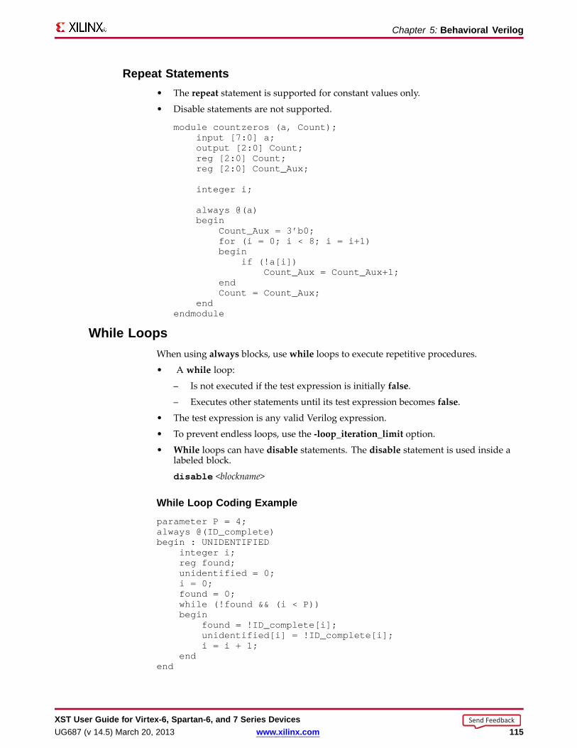
Chapter 5: Behavioral Verilog
Repeat Statements• The repeat statement is supported for constant values only.
• Disable statements are not supported.
module countzeros (a, Count);input [7:0] a;output [2:0] Count;reg [2:0] Count;reg [2:0] Count_Aux;
integer i;
always @(a)begin
Count_Aux = 3’b0;for (i = 0; i < 8; i = i+1)begin
if (!a[i])Count_Aux = Count_Aux+1;
endCount = Count_Aux;
endendmodule
While LoopsWhen using always blocks, use while loops to execute repetitive procedures.
• A while loop:
– Is not executed if the test expression is initially false.
– Executes other statements until its test expression becomes false.
• The test expression is any valid Verilog expression.
• To prevent endless loops, use the -loop_iteration_limit option.
• While loops can have disable statements. The disable statement is used inside alabeled block.
disable <blockname>
While Loop Coding Exampleparameter P = 4;always @(ID_complete)begin : UNIDENTIFIED
integer i;reg found;unidentified = 0;i = 0;found = 0;while (!found && (i < P))begin
found = !ID_complete[i];unidentified[i] = !ID_complete[i];i = i + 1;
endend
XST User Guide for Vir tex-6, Spar tan-6, and 7 Series DevicesUG687 (v 14.5) March 20, 2013 www.xilinx.com 115
Send Feedback
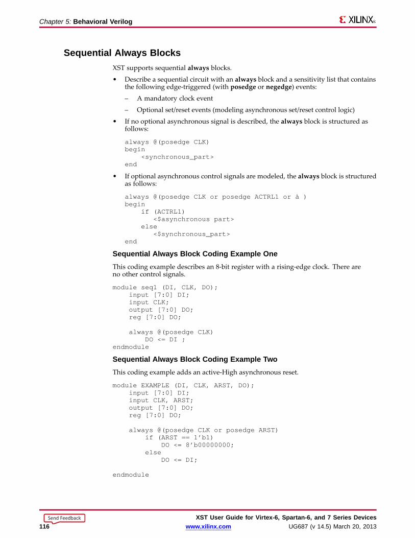
Chapter 5: Behavioral Verilog
Sequential Always Bloc ksXST supports sequential always blocks.
• Describe a sequential circuit with an always block and a sensitivity list that containsthe following edge-triggered (with posedge or negedge) events:
– A mandatory clock event
– Optional set/reset events (modeling asynchronous set/reset control logic)
• If no optional asynchronous signal is described, the always block is structured asfollows:
always @(posedge CLK)begin
<synchronous_part>end
• If optional asynchronous control signals are modeled, the always block is structuredas follows:
always @(posedge CLK or posedge ACTRL1 or à )begin
if (ACTRL1)<$asynchronous part>
else<$synchronous_part>
end
Sequential Always Bloc k Coding Example OneThis coding example describes an 8-bit register with a rising-edge clock. There areno other control signals.
module seq1 (DI, CLK, DO);input [7:0] DI;input CLK;output [7:0] DO;reg [7:0] DO;
always @(posedge CLK)DO <= DI ;
endmodule
Sequential Always Bloc k Coding Example TwoThis coding example adds an active-High asynchronous reset.
module EXAMPLE(DI, CLK, ARST, DO);input [7:0] DI;input CLK, ARST;output [7:0] DO;reg [7:0] DO;
always @(posedge CLK or posedge ARST)if (ARST == 1’b1)
DO <= 8’b00000000;else
DO <= DI;
endmodule
XST User Guide for Vir tex-6, Spar tan-6, and 7 Series Devices116 www.xilinx.com UG687 (v 14.5) March 20, 2013
Send Feedback

Chapter 5: Behavioral Verilog
Sequential Always Bloc k Coding Example ThreeThis coding example describes:
• An active-High asynchronous reset, and
• An active-Low asynchronous set.
module EXAMPLE(DI, CLK, ARST, ASET, DO);input [7:0] DI;input CLK, ARST, ASET;output [7:0] DO;reg [7:0] DO;
always @(posedge CLK or posedge ARST or negedge ASET)if (ARST == 1’b1)
DO <= 8’b00000000;else if (ASET == 1’b1)
DO <= 8’b11111111;else
DO <= DI;
endmodule
Sequential Always Bloc k Coding Example FourThis coding example describes:
• A register with no asynchronous set/reset, and
• A synchronous reset.
module EXAMPLE(DI, CLK, SRST, DO);input [7:0] DI;input CLK, SRST;output [7:0] DO;reg [7:0] DO;
always @(posedge CLK)if (SRST == 1’b1)
DO <= 8’b00000000;else
DO <= DI;
endmodule
XST User Guide for Vir tex-6, Spar tan-6, and 7 Series DevicesUG687 (v 14.5) March 20, 2013 www.xilinx.com 117
Send Feedback
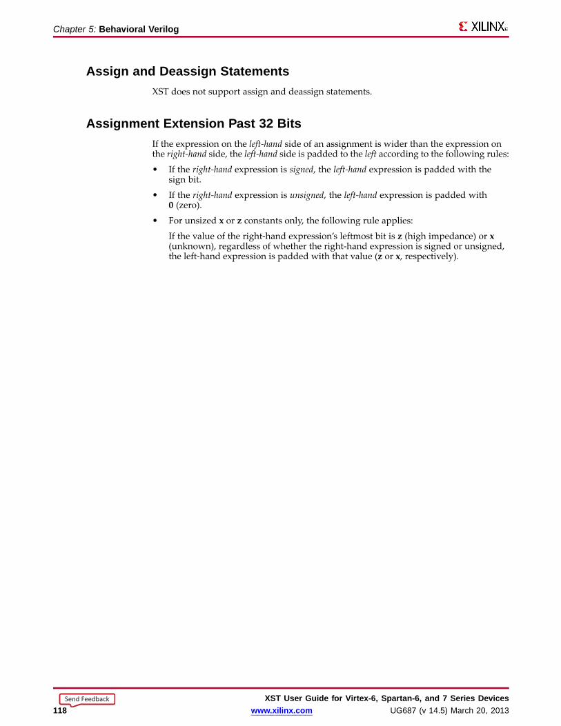
Chapter 5: Behavioral Verilog
Assign and Deassign StatementsXST does not support assign and deassign statements.
Assignment Extension Past 32 BitsIf the expression on the left-hand side of an assignment is wider than the expression onthe right-hand side, the left-hand side is padded to the left according to the following rules:
• If the right-hand expression is signed, the left-hand expression is padded with thesign bit.
• If the right-hand expression is unsigned, the left-hand expression is padded with0 (zero).
• For unsized x or z constants only, the following rule applies:
If the value of the right-hand expression’s leftmost bit is z (high impedance) or x(unknown), regardless of whether the right-hand expression is signed or unsigned,the left-hand expression is padded with that value (z or x, respectively).
XST User Guide for Vir tex-6, Spar tan-6, and 7 Series Devices118 www.xilinx.com UG687 (v 14.5) March 20, 2013
Send Feedback
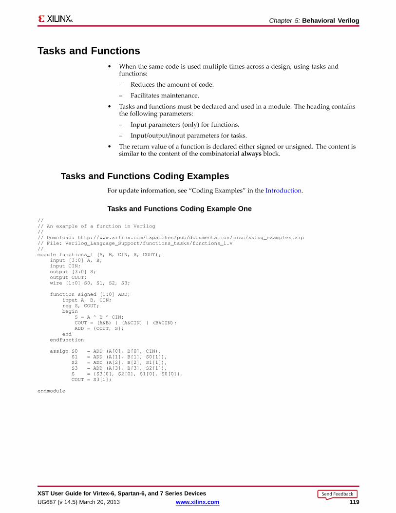
Chapter 5: Behavioral Verilog
Tasks and Functions• When the same code is used multiple times across a design, using tasks and
functions:
– Reduces the amount of code.
– Facilitates maintenance.
• Tasks and functions must be declared and used in a module. The heading containsthe following parameters:
– Input parameters (only) for functions.
– Input/output/inout parameters for tasks.
• The return value of a function is declared either signed or unsigned. The content issimilar to the content of the combinatorial always block.
Tasks and Functions Coding ExamplesFor update information, see “Coding Examples” in the Introduction.
Tasks and Functions Coding Example One//// An example of a function in Verilog//// Download: http://www.xilinx.com/txpatches/pub/documentation/misc/xstug_examples.zip// File: Verilog_Language_Support/functions_tasks/functions_1.v//module functions_1 (A, B, CIN, S, COUT);
input [3:0] A, B;input CIN;output [3:0] S;output COUT;wire [1:0] S0, S1, S2, S3;
function signed [1:0] ADD;input A, B, CIN;reg S, COUT;begin
S = A ^ B ^ CIN;COUT= (A&B) | (A&CIN) | (B%CIN);ADD = {COUT, S};
endendfunction
assign S0 = ADD (A[0], B[0], CIN),S1 = ADD (A[1], B[1], S0[1]),S2 = ADD (A[2], B[2], S1[1]),S3 = ADD (A[3], B[3], S2[1]),S = {S3[0], S2[0], S1[0], S0[0]},COUT= S3[1];
endmodule
XST User Guide for Vir tex-6, Spar tan-6, and 7 Series DevicesUG687 (v 14.5) March 20, 2013 www.xilinx.com 119
Send Feedback

Chapter 5: Behavioral Verilog
Tasks and Functions Coding Example TwoIn this coding example, the same functionality is described with a task.
//// Verilog tasks//// Download: http://www.xilinx.com/txpatches/pub/documentation/misc/xstug_examples.zip// File: Verilog_Language_Support/functions_tasks/tasks_1.v//module tasks_1 (A, B, CIN, S, COUT);
input [3:0] A, B;input CIN;output [3:0] S;output COUT;reg [3:0] S;reg COUT;reg [1:0] S0, S1, S2, S3;
task ADD;input A, B, CIN;output [1:0] C;reg [1:0] C;reg S, COUT;begin
S = A ^ B ^ CIN;COUT= (A&B) | (A&CIN) | (B&CIN);C = {COUT, S};
endendtask
always @(A or B or CIN)begin
ADD (A[0], B[0], CIN, S0);ADD (A[1], B[1], S0[1], S1);ADD (A[2], B[2], S1[1], S2);ADD (A[3], B[3], S2[1], S3);S = {S3[0], S2[0], S1[0], S0[0]};COUT= S3[1];
end
endmodule
Recur sive Tasks and FunctionsVerilog-2001 supports recursive tasks and functions.
• You can use recursion only with the automatic keyword.
• The number of recursions is automatically limited to prevent endless recursivecalls. The default is 64.
• Use -recursion_iteration_limit to set the number of allowed recursive calls.
Recur sive Tasks and Functions Coding Examplefunction automatic [31:0] fac;
input [15:0] n;if (n == 1)
fac = 1;else
fac = n * fac(n-1); //recursive function callendfunction
Constant FunctionsXST supports function calls to calculate constant values.
XST User Guide for Vir tex-6, Spar tan-6, and 7 Series Devices120 www.xilinx.com UG687 (v 14.5) March 20, 2013
Send Feedback

Chapter 5: Behavioral Verilog
Constant Functions Coding Example//// A function that computes and returns a constant value//// Download: http://www.xilinx.com/txpatches/pub/documentation/misc/xstug_examples.zip// File: Verilog_Language_Support/functions_tasks/functions_constant.v//module functions_constant (clk, we, a, di, do);
parameter ADDRWIDTH= 8;parameter DATAWIDTH= 4;input clk;input we;input [ADDRWIDTH-1:0] a;input [DATAWIDTH-1:0] di;output [DATAWIDTH-1:0] do;
function integer getSize;input addrwidth;begin
getSize = 2**addrwidth;end
endfunction
reg [DATAWIDTH-1:0] ram [getSize(ADDRWIDTH)-1:0];
always @(posedge clk) beginif (we)
ram[a] <= di;endassign do = ram[a];
endmodule
Bloc king and Non-Bloc king Procedural AssignmentsBlocking and non-blocking procedural assignments have time control built into theirrespective assignment statements.
• The pound sign (#) and the at sign (@) are time control statements.
• These statements delay execution of the statement following them until the specifiedevent is evaluated as true.
• The pound (#) delay is ignored for synthesis.
Bloc king Procedural Assignment Syntax Coding Example Onereg a;a = #10 (b | c);
Bloc king Procedural Assignment Syntax Coding Example Two (Alternate)if (in1) out = 1’b0;else out = in2;
This assignment:
• Blocks the current process from continuing to execute additional statements at thesame time.
• Should be used mainly in simulation.
XST User Guide for Vir tex-6, Spar tan-6, and 7 Series DevicesUG687 (v 14.5) March 20, 2013 www.xilinx.com 121
Send Feedback
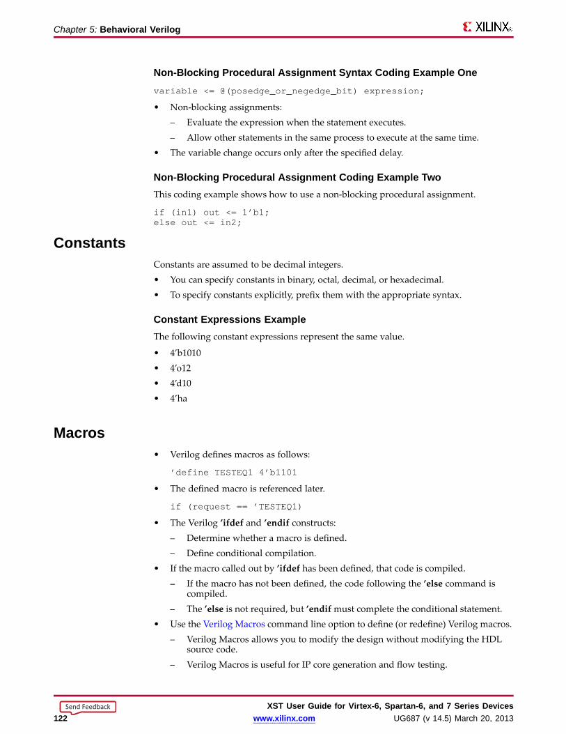
Chapter 5: Behavioral Verilog
Non-Bloc king Procedural Assignment Syntax Coding Example Onevariable <= @(posedge_or_negedge_bit) expression;
• Non-blocking assignments:– Evaluate the expression when the statement executes.– Allow other statements in the same process to execute at the same time.
• The variable change occurs only after the specified delay.
Non-Bloc king Procedural Assignment Coding Example TwoThis coding example shows how to use a non-blocking procedural assignment.
if (in1) out <= 1’b1;else out <= in2;
ConstantsConstants are assumed to be decimal integers.• You can specify constants in binary, octal, decimal, or hexadecimal.• To specify constants explicitly, prefix them with the appropriate syntax.
Constant Expressions ExampleThe following constant expressions represent the same value.
• 4’b1010• 4’o12• 4’d10• 4’ha
Macros• Verilog defines macros as follows:
’define TESTEQ1 4’b1101
• The defined macro is referenced later.
if (request == ’TESTEQ1)
• The Verilog ’ifdef and ’endif constructs:– Determine whether a macro is defined.– Define conditional compilation.
• If the macro called out by ’ifdef has been defined, that code is compiled.– If the macro has not been defined, the code following the ’else command is
compiled.– The ’else is not required, but ’endifmust complete the conditional statement.
• Use the Verilog Macros command line option to define (or redefine) Verilog macros.– Verilog Macros allows you to modify the design without modifying the HDL
source code.– Verilog Macros is useful for IP core generation and flow testing.
XST User Guide for Vir tex-6, Spar tan-6, and 7 Series Devices122 www.xilinx.com UG687 (v 14.5) March 20, 2013
Send Feedback
Chapter 5: Behavioral Verilog
Macros Coding Example One’define myzero 0assign mysig = ’myzero;
Macros Coding Example Two’ifdef MYVARmodule if_MYVAR_is_declared;...endmodule’elsemodule if_MYVAR_is_not_declared;...endmodule’endif
Include FilesVerilog allows you to separate HDL source code into more than one file.
• Use either of these methods to reference the additional files:
– File Inclusion Method
– Design Project File Method
• Xilinx® recommends the design project file method.
File Inclusion MethodXilinx does not recommend the file inclusion method.
• To reference the code in another file, use the following syntax in the current file:
’include " path/file-to-be-included "
• The path is relative or absolute.
• Multiple ’include statements are allowed in the same Verilog file. This makesyour code more manageable in a team design environment in which different filesdescribe different modules.
• To allow the file in your ’include statement to be recognized, identify the directoryin which it resides, either to ISE® Design Suite or to XST.
– Add the file to your project directory.
ISE Design Suite searches the project directory by default.
– Include a relative or absolute path in the ’include statement.
This path points ISE Design Suite to a directory other than the project directory.
– Use Verilog Include Directories (-vlgincdir).
This option points XST directly to the include file directory.
• If the include file is required for ISE Design Suite to construct the design hierarchy,the file must:
– Reside in the project directory, or
– Be referenced by a relative or absolute path. The file need not be added to theproject.
XST User Guide for Vir tex-6, Spar tan-6, and 7 Series DevicesUG687 (v 14.5) March 20, 2013 www.xilinx.com 123
Send Feedback

Chapter 5: Behavioral Verilog
Design Project File MethodXilinx recommends the design project file method.
• To make a Verilog file visible to the rest of your project, list it in the XST designproject file.
• If you include a Verilog file using the File Inclusion Method, do not also list it in theXST design project file. Doing so generates an error message.
ERROR:HDLCompiler:687 - "include_sub.v" Line 1: Illegalredeclaration of module <sub>.
• This error may occur if you add Verilog files with multiple inclusions to aproject. Because ISE Design Suite adds them to the XST design project file, amultiple-definition conflict can result.
Behavioral Verilog CommentsBehavioral Verilog comments are similar to the comments in such languages as C++.
One-Line CommentsOne-line comments start with a double forward slash (//).
// This is a one-line comment.
Multiple-Line Bloc k CommentsMultiple-line block comments start with /* and end with */.
/* This is amultiple-linecomment.
*/
Generate StatementsBehavioral Verilog generate statements:
• Allow you to create:
– Parameterized and scalable code.
– Repetitive or scalable structures.
– Functionality conditional on a particular criterion being met.
• Are resolved during Verilog elaboration.
• Are conditionally instantiated into your design.
• Are described within a module scope.
• Start with a generate keyword.
• End with an endgenerate keyword.
XST User Guide for Vir tex-6, Spar tan-6, and 7 Series Devices124 www.xilinx.com UG687 (v 14.5) March 20, 2013
Send Feedback

Chapter 5: Behavioral Verilog
Structures Created Using Generate StatementsStructures likely to be created using a generate statement include:
• Primitive or module instances
• Initial or always procedural blocks
• Continuous assignments
• Net and variable declarations
• Parameter redefinitions
• Task or function definitions
Suppor ted Generate StatementsXST supports all Behavioral Verilog generate statements:
• generate-loop (generate-for)
• generate-conditional (generate-if-else)
• generate-case (generate-case)
Generate Loop StatementsUse a generate-for loop to create one or more instances that can be placed inside amodule.
Use the generate-for loop the same way you use a normal Verilog for loop, with thefollowing limitations:
• The index for a generate-for loop has a genvar variable.
• The assignments in the for loop control refers to the genvar variable.
• The contents of the for loop are enclosed by begin and end statements.
• The begin statement is named with a unique qualifier.
Generate Loop Statement 8-Bit Adder Coding Examplegenerategenvar i;
for (i=0; i<=7; i=i+1)begin : for_name
adder add (a[8*i+7 : 8*i], b[8*i+7 : 8*i], ci[i], sum_for[8*i+7 : 8*i], c0_or[i+1]);end
endgenerate
Generate Conditional StatementsA generate-if-else statement conditionally controls which objects are generated.
• Each branch of the if-else statement is enclosed by begin and end statements.
• The begin statement is named with a unique qualifier.
XST User Guide for Vir tex-6, Spar tan-6, and 7 Series DevicesUG687 (v 14.5) March 20, 2013 www.xilinx.com 125
Send Feedback
Chapter 5: Behavioral Verilog
Generate Conditional Statement Coding ExampleThis coding example instantiates two different implementations of a multiplier based onthe width of data words.
generateif (IF_WIDTH < 10)
begin : if_namemultiplier_imp1 # (IF_WIDTH) u1 (a, b, sum_if);
endelse
begin : else_namemultiplier_imp2 # (IF_WIDTH) u2 (a, b, sum_if);
endendgenerate
Generate Case StatementsA generate-case statement conditionally controls which objects are generated underwhich conditions.
• Each branch in a generate-case statement is enclosed by begin and end statements.
• The begin statement is named with a unique qualifier.
Behavioral Verilog Generate Case Statements Coding ExampleThis coding example instantiates more than two different implementations of an Adderbased on the width of data words.
generatecase (WIDTH)
1:begin : case1_name
adder #(WIDTH*8) x1 (a, b, ci, sum_case, c0_case);end
2:begin : case2_name
adder #(WIDTH*4) x2 (a, b, ci, sum_case, c0_case);end
default:begin : d_case_name
adder x3 (a, b, ci, sum_case, c0_case);end
endcaseendgenerate
XST User Guide for Vir tex-6, Spar tan-6, and 7 Series Devices126 www.xilinx.com UG687 (v 14.5) March 20, 2013
Send Feedback
Chapter 6
Mixed Language SupportXST supports VHDL and Verilog mixed language projects except as otherwise noted.
Mixing VHDL and Verilog• Mixing VHDL and Verilog is restricted to design unit (cell) instantiation.
– A Verilog module can be instantiated from VHDL code.– A VHDL entity can be instantiated from Verilog code.– No other mixing between VHDL and Verilog is supported. For example, you
cannot embed Verilog source code directly in VHDL source code.• In a VHDL design, a restricted subset of VHDL types, generics, and ports is allowed
on the boundary to a Verilog module.• In a Verilog design, a restricted subset of Verilog types, parameters, and ports is
allowed on the boundary to a VHDL entity or configuration.• XST binds VHDL design units to a Verilog module during HDL elaboration.• The VHDL and Verilog files that make up a project are specified in a unique HDL
project file. For more information, see Chapter 2, Creating and Synthesizing anXST Project.
Instantiation• Component instantiation based on default binding is used for binding Verilog
modules to a VHDL design unit.• For a Verilog module instantiation in VHDL, XST does not support:
– Configuration specification– Direct instantiation– Component configurations
VHDL and Verilog Libraries• VHDL and Verilog libraries are logically unified.• The default work directory for compilation (xsthdpdir ) is available to both VHDL
and Verilog.• The xhdp.ini mechanism:
– Maps a logical library name to a physical directory name on the host file system.– Is available for both VHDL and Verilog.
• Mixed language projects accept a search order for searching unified logical librariesin design units (cells). XST follows this search order during elaboration to select andbind a VHDL entity or a Verilog module to the mixed language project.
XST User Guide for Vir tex-6, Spar tan-6, and 7 Series DevicesUG687 (v 14.5) March 20, 2013 www.xilinx.com 127
Send Feedback

Chapter 6: Mixed Langua ge Suppor t
VHDL and Verilog Boundar y RulesThe boundary between VHDL and Verilog is enforced at the design unit level.• A VHDL entity or architecture can instantiate a Verilog module. See Instantiating
VHDL in Verilog.• A Verilog module can instantiate a VHDL entity. See Instantiating Verilog in VHDL.
Instantiating VHDL in VerilogTo instantiate a VHDL design unit in a Verilog design:
1. Declare a module name with the same as name as the VHDL entity that you want toinstantiate (optionally followed by an architecture name).
2. Perform a normal Verilog instantiation.
XST Limitations (VHDL in Verilog)XST has the following limitations when instantiating a VHDL design unit in a Verilogmodule:
• The only VHDL construct that can be instantiated in a Verilog design is a VHDLentity.– No other VHDL constructs are visible to Verilog code.– XST uses the entity-architecture pair as the Verilog-VHDL boundary.
• Use explicit port association. Specify formal and effective port names in the portmap.
• All parameters are passed at instantiation, even if they are unchanged.• The parameter override is named and not ordered. The parameter override occurs
through instantiation, not through defparams.
XST BindingXST performs binding during elaboration. During binding:1. XST searches for a Verilog module with the same name as the instantiated module
in the:a. User-specified list of unified logical libraries.b. User-specified order.
For more information, see Library Search Order (LSO) Rules.2. XST ignores any architecture name specified in the module instantiation.3. If XST finds the Verilog module, XST binds the name.4. If XST does not find the Verilog module:
• XST treats the Verilog module as a VHDL entity.• XST searches for the first VHDL entity matching the name using a case sensitive
search for a VHDL entity in the:a. User-specified list of unified logical libraries.b. User-specified order.
Note This assumes that a VHDL design unit was stored with extendedidentifier.
XST User Guide for Vir tex-6, Spar tan-6, and 7 Series Devices128 www.xilinx.com UG687 (v 14.5) March 20, 2013
Send Feedback

Chapter 6: Mixed Langua ge Suppor t
XST Limitations (Verilog from VHDL)XST has the following limitations when instantiating a VHDL design unit from a Verilogmodule:• Use explicit port association. Specify formal and effective port names in the port
map.• All parameters are passed at instantiation, even if they are unchanged.• The parameter override is named and not ordered. The parameter override occurs
through instantiation, and not through defparams.
Accepted Coding Exampleff #(.init(2’b01)) u1 (.sel(sel), .din(din), .dout(dout));
NOT Accepted Coding Exampleff u1 (.sel(sel), .din(din), .dout(dout));defparam u1.init = 2’b01;
Instantiating Verilog in VHDL• To instantiate a Verilog module in a VHDL design:
1. Declare a VHDL component with the same name as the Verilog module to beinstantiated.
2. Observe case sensitivity.3. If the module name is not all lowercase, use case to preserve the module case.
– ISE® Design SuiteProcess > Properties > Synthesis Options > Case > Maintain
– Command LineSet case to maintain
4. Instantiate the Verilog component as if you were instantiating a VHDLcomponent.
• You could attempt to bind this component to a specific design unit from a specificlibrary by using a VHDL configuration declaration. Such binding is not supported.Only default Verilog module binding is supported.
• The only Verilog construct that can be instantiated in a VHDL design is a Verilogmodule. No other Verilog constructs are visible to VHDL code.
• During elaboration, XST treats all components subject to default binding as designunits with the same name as the corresponding component name.
• During binding, XST treats a component name as a VHDL design unit name andsearches for it in the logical library work .– If XST finds a VHDL design unit, XST binds it.– If XST does not find a VHDL design unit:
♦ XST treats the component name as a Verilog module name.♦ XST searches for it using a case sensitive search.
• XST searches for the Verilog module in the user-specified list of unified logicallibraries in the user-specified search order. For more information, see Library SearchOrder (LSO) Files.
• XST selects the first Verilog module matching the name, and binds it.• Since libraries are unified, a Verilog cell with the same name as a VHDL design unit
cannot exist in the same logical library.• A newly-compiled cell or unit overrides a previously-compiled cell or unit.
XST User Guide for Vir tex-6, Spar tan-6, and 7 Series DevicesUG687 (v 14.5) March 20, 2013 www.xilinx.com 129
Send Feedback

Chapter 6: Mixed Langua ge Suppor t
Generics Suppor tXST supports the following VHDL generic types and their Verilog equivalents for mixedlanguage designs.
• integer
• real
• string
• boolean
XST User Guide for Vir tex-6, Spar tan-6, and 7 Series Devices130 www.xilinx.com UG687 (v 14.5) March 20, 2013
Send Feedback

Chapter 6: Mixed Langua ge Suppor t
Por t MappingXST supports:
• Port Mapping for VHDL Instantiated in Verilog
• Port Mapping for Verilog Instantiated in VHDL
Por t Mapping for VHDL Instantiated in VerilogWhen a VHDL entity is instantiated in a Verilog module, formal ports may have thefollowing characteristics:
• Allowed directions
– in
– out
– inout
• Unsupported directions
– buffer
– linkage
• Allowed data types
– bit
– bit_vector
– std_logic
– std_ulogic
– std_logic_vector
– std_ulogic_vector
Por t Mapping for Verilog Instantiated in VHDLWhen a Verilog module is instantiated in a VHDL entity or architecture, formal portsmay have the following characteristics.
• Allowed directions
– input
– output
– inout
• Allowed data types
– wire
– reg
• XST does not support:
– Connection to bi-directional pass options in Verilog.
– Unnamed Verilog ports for mixed language boundaries.
Use an equivalent component declaration to connect to a case sensitive port in a Verilogmodule. XST assumes Verilog ports are in all lowercase.
XST User Guide for Vir tex-6, Spar tan-6, and 7 Series DevicesUG687 (v 14.5) March 20, 2013 www.xilinx.com 131
Send Feedback

Chapter 6: Mixed Langua ge Suppor t
Librar y Search Order (LSO) FilesLibrary Search Order (LSO) files specify the search order that XST uses to link thelibraries used in VHDL and Verilog mixed language designs.
• XST searches the files specified in the project file in the order in which they appearin the LSO file.
• XST uses the default search order when:
– The DEFAULT_SEARCH_ORDER keyword appears in the LSO file, or
– The LSO file is not specified.
Specifying LSO Files in ISE Design SuiteThe default name of the Library Search Order (LSO) file is project_name.lso .
• If project_name.lso exists, it is preserved and used as is.
• If project_name.lso does not exist, ISE® Design Suite:
– Creates a default project_name.lso file.
– Places the DEFAULT_SEARCH_ORDER keyword in the first line of the file.
• The name of the project is the name of the top-level block.
Specifying LSO Files in Command Line Mode• The Library Search Order (LSO) (-lso) command line option specifies the Library
Search Order (LSO) file.
• If -lso is omitted, XST uses the default library search order without an LSO file.
LSO RulesWhen XST processes a mixed language project, the search order rules depend on thecontent of the Library Search Order (LSO) file:
• Empty LSO File
• DEFAULT_SEARCH_ORDER Keyword Only
• DEFAULT_SEARCH_ORDER Keyword and List of Libraries
• List of Libraries Only
• DEFAULT_SEARCH_ORDER Keyword and Non-Existent Library Name
Empty LSO FilesIf the Library Search Order (LSO) file is empty:
• XST warns that the LSO file is empty.
• XST searches the files specified in the project file using the default library searchorder.
• XST adds the list of libraries to the LSO file in the order that they appear in theproject file.
XST User Guide for Vir tex-6, Spar tan-6, and 7 Series Devices132 www.xilinx.com UG687 (v 14.5) March 20, 2013
Send Feedback

Chapter 6: Mixed Langua ge Suppor t
DEFAULT_SEARCH_ORDER Keyword OnlyWhen the LSO file contains only the DEFAULT_SEARCH_ORDER keyword:
• XST searches the specified library files in the order in which they appear in theproject file.
• XST removes the DEFAULT_SEARCH_ORDER keyword from the LSO file.
• XST adds the list of libraries to the LSO file in the order in which they appearin the project file.
Search Order Example1. For a project file, my_proj.prj , with the following content:
vhdl vhlib1 f1.vhdverilog rtfllib f1.vvhdl vhlib2 f3.vhd
2. And an LSO file, my_proj.lso , created by ISE® Design Suite, with the followingcontent:
DEFAULT_SEARCH_ORDER
3. XST uses the following search order:
vhlib1rtfllibvhlib2
The same content appears in the updated my_proj.lso file after processing.
DEFAULT_SEARCH_ORDER Keyword and List of Libraries• When the LSO file contains:
– The DEFAULT_SEARCH_ORDER keyword, and
– A list of libraries
• XST does the following:
– Searches the specified library files in the order in which they appear in theproject file.
– Ignores the list of library files in the LSO file.
– Leaves the LSO file unchanged.
XST User Guide for Vir tex-6, Spar tan-6, and 7 Series DevicesUG687 (v 14.5) March 20, 2013 www.xilinx.com 133
Send Feedback
Chapter 6: Mixed Langua ge Suppor t
Search Order Example1. For a project file my_proj.prj with the following content:
vhdl vhlib1 f1.vhdverilog rtfllib f1.vvhdl vhlib2 f3.vhd
2. And an LSO file my_proj.lso with the following content:
rtfllibvhlib2vhlib1DEFAULT_SEARCH_ORDER
3. XST uses the following search order:
vhlib1rtfllibvhlib2
4. After processing, the content of my_proj.lso remains unchanged:
rtfllibvhlib2vhlib1DEFAULT_SEARCH_ORDER
List of Libraries OnlyWhen the LSO file contains a list of libraries without the DEFAULT_SEARCH_ORDERkeyword:
• XST searches the library files in the order in which they appear in the LSO file.
• XST leaves the LSO file unchanged.
File Search Example1. For a project file my_proj.prj with the following content:
vhdl vhlib1 f1.vhdverilog rtfllib f1.vvhdl vhlib2 f3.vhd
2. And an LSO file my_proj.lso with the following content:
rtfllibvhlib2vhlib1
3. XST uses the following search order:
rtfllibvhlib2vhlib1
4. After processing, the content of my_proj.lso is:
rtfllibvhlib2vhlib1
XST User Guide for Vir tex-6, Spar tan-6, and 7 Series Devices134 www.xilinx.com UG687 (v 14.5) March 20, 2013
Send Feedback

Chapter 6: Mixed Langua ge Suppor t
DEFAULT_SEARCH_ORDER Keyword and Non-Existent Librar y NameXST ignores a library when the LSO file:
• Contains a library name that does not exist in the project or INI file, and
• Does not contain the DEFAULT_SEARCH_ORDER keyword.
Search Order Example1. For a project file my_proj.prj with the following contents:
vhdl vhlib1 f1.vhdverilog rtfllib f1.vvhdl vhlib2 f3.vhd
2. And an LSO file my_proj.lso with the following content:
personal_librtfllibvhlib2vhlib1
3. XST uses the following search order:
rtfllibvhlib2vhlib1
4. After processing, the content of my_proj.lso is:
rtfllibvhlib2vhlib1
XST User Guide for Vir tex-6, Spar tan-6, and 7 Series DevicesUG687 (v 14.5) March 20, 2013 www.xilinx.com 135
Send Feedback

XST User Guide for Vir tex-6, Spar tan-6, and 7 Series Devices136 www.xilinx.com UG687 (v 14.5) March 20, 2013
Send Feedback
Chapter 7
HDL Coding TechniquesHardware Description Language (HDL) coding techniques allow you to:
• Describe the most common functionalities found in digital logic circuits.
• Take advantage of the architectural features of Xilinx® devices.
For instructions on accessing the synthesis templates from ISE® Design Suite, see theISE Design Suite Help.
Advantages of VHDL• Enforces stricter rules, in particular strongly typed, less permissive and error-prone
• Initialization of RAM components in the HDL source code is easier (Verilog initialblocks are less convenient)
• Package support
• Custom types
• Enumerated types
• No reg versus wire confusion
Advantages of Verilog• Extension to System Verilog (currently not supported by XST)
• C-like syntax
• Results in more compact code
• Block commenting
• No heavy component instantiation as in VHDL
XST User Guide for Vir tex-6, Spar tan-6, and 7 Series DevicesUG687 (v 14.5) March 20, 2013 www.xilinx.com 137
Send Feedback

Chapter 7: HDL Coding Techniques
Macro Inference Flow OverviewMacros are inferred during three stages of the XST synthesis flow.
• Basic macros are inferred during HDL Synthesis.
• Complex macros are inferred during Advanced HDL Synthesis.
• Other macros are inferred during Low-Level Optimizations, when timinginformation is available to make more fully-informed decisions.
• Macros inferred during Advanced HDL Synthesis are usually the result of anaggregation of several basic macros previously inferred during HDL Synthesis.In most cases, the XST inference engine can perform this grouping regardless ofhierarchical boundaries, unless Keep Hierarchy has been set to yes in order toprevent it.
Example
A block RAM is inferred by combining RAM core functionality described in oneuser-defined hierarchical block, with a Register described in a different user-definedhierarchy. This allows you to structure the HDL project in a modular way, ensuringthat XST can recognize relationships among design elements described in differentVHDL entities and Verilog modules.
• Do not describe every basic bit-level element in its own separate hierarchy.
– Doing so may prevent you from leveraging the RTL inference capabilities ofthe synthesis tool.
– For information structuring the HDL source code, see the design projects inExtended DSP Inferencing.
XST User Guide for Vir tex-6, Spar tan-6, and 7 Series Devices138 www.xilinx.com UG687 (v 14.5) March 20, 2013
Send Feedback
Chapter 7: HDL Coding Techniques
Flip-Flops and Register s• XST recognizes Flip-Flops and Registers with the following control signals:
– Rising or falling-edge clocks
– Asynchronous Set/Reset
– Synchronous Set/Reset
– Clock Enable
• Flip-Flops and Registers are described with:
– sequential process (VHDL)
– always block (Verilog)
• The process or always block sensitivity list should list:
– The clock signal
– All asynchronous control signals
• For more information on describing sequential logic in HDL, see:
– Chapter 3, VHDL Support
– Chapter 4, XST Verilog Support
Flip-Flops and Register s InitializationTo initialize the content of a Register at circuit power-up, specify a default value for thesignal modeling it.
Flip-Flops and Register s Initialization in VHDLTo initialize the content of a Register at circuit power-up in VHDL, declare a signalsuch as:
signal example1 : std_logic := ’1’;signal example2 : std_logic_vector(3 downto 0) := (others => ’0’);signal example3 : std_logic_vector(3 downto 0) := "1101";
Flip-Flops and Register s Initialization in VerilogDescribe initial contents in Verilog as follows:
reg example1 = ’b1 ;reg [15:0] example2 = 16’b1111111011011100;reg [15:0] example3 = 16’hFEDC;
The synthesized Flip-Flops are initialized to the specified value on the target devicewhen the circuit global reset is activated at circuit power-up.
Flip-Flops and Register s Contr ol SignalsFlip-Flops and Registers control signals include:
• Clocks
• Asynchronous and synchronous set and reset signals
• Clock enable
XST User Guide for Vir tex-6, Spar tan-6, and 7 Series DevicesUG687 (v 14.5) March 20, 2013 www.xilinx.com 139
Send Feedback

Chapter 7: HDL Coding Techniques
Coding Guidelines• These coding guidelines:
– Minimize slice logic utilization.
– Maximize circuit performance.
– Utilize device resources such as block RAM components and DSP blocks.
• Do not set or reset Registers asynchronously.
– Control set remapping becomes impossible.
– Sequential functionality in device resources such as block RAM components andDSP blocks can be set or reset synchronously only.
– You will be unable to leverage device resources resources, or they will beconfigured sub-optimally.
– Use synchronous initialization instead.
• Use Asynchronous to Synchronous if your own coding guidelines require Registersto be set or reset asynchronously. This allows you to assess the benefits of usingsynchronous set/reset.
• Do not describe Flip-Flops with both a set and a reset.
– No Flip-Flop primitives feature both a set and a reset, whether synchronousor asynchronous.
– If not rejected by the software, Flip-Flop primitives featuring both a set and areset may adversely affect area and performance.
• Do not describe Flip-Flops with both an asynchronous reset and an asynchronousset. XST rejects such Flip-Flops rather than retargeting them to a costly equivalentmodel.
• Avoid operational set/reset logic whenever possible. There may be other, lessexpensive, ways to achieve the desired effect, such as taking advantage of the circuitglobal reset by defining an initial contents.
• Always describe the clock enable, set, and reset control inputs of Flip-Flop primitivesas active-High. If they are described as active-Low, the resulting inverter logic willpenalize circuit performance.
Flip-Flops and Register s Related Constraints• Pack I/O Registers Into IOBs
• Register Duplication
• Equivalent Register Removal
• Register Balancing
• Asynchronous to Synchronous
For other ways to control implementation of Flip-Flops and Registers, see MappingLogic to LUTs.
XST User Guide for Vir tex-6, Spar tan-6, and 7 Series Devices140 www.xilinx.com UG687 (v 14.5) March 20, 2013
Send Feedback

Chapter 7: HDL Coding Techniques
Flip-Flops and Register s Repor ting• Registers are inferred and reported during HDL Synthesis.
• Registers are expanded to individual Flip-Flops after Advanced HDL Synthesis.
• The number of Registers inferred during HDL Synthesis may not precisely equal thenumber of Flip-Flop primitives in the Design Summary section.
• The number of Flip-Flop primitives depends on the following processes:
– Absorption of Registers into DSP blocks or block RAM components
– Register duplication
– Removal of constant or equivalent Flip-Flops
– Register balancing
Flip-Flops and Register s Repor ting Example=========================================================================* HDL Synthesis *=========================================================================
Synthesizing Unit registers_5>.Found 4-bit register for signal Q>.Summary:
inferred 4 D-type flip-flop(s).Unit registers_5> synthesized.
=========================================================================HDL Synthesis Report
Macro Statistics# Registers : 14-bit register : 1
=========================================================================
=========================================================================* Advanced HDL Synthesis *=========================================================================(…)
=========================================================================Advanced HDL Synthesis Report
Macro Statistics# Registers : 4Flip-Flops : 4
=========================================================================
Flip-Flops and Register s Coding ExamplesFor update information, see “Coding Examples” in the Introduction.
XST User Guide for Vir tex-6, Spar tan-6, and 7 Series DevicesUG687 (v 14.5) March 20, 2013 www.xilinx.com 141
Send Feedback
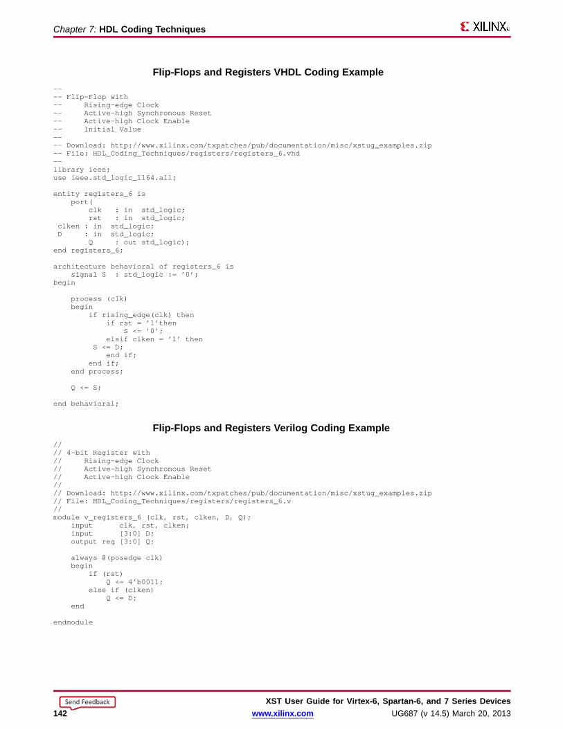
Chapter 7: HDL Coding Techniques
Flip-Flops and Register s VHDL Coding Example---- Flip-Flop with-- Rising-edge Clock-- Active-high Synchronous Reset-- Active-high Clock Enable-- Initial Value---- Download: http://www.xilinx.com/txpatches/pub/documentation/misc/xstug_examples.zip-- File: HDL_Coding_Techniques/registers/registers_6.vhd--library ieee;use ieee.std_logic_1164.all;
entity registers_6 isport(
clk : in std_logic;rst : in std_logic;
clken : in std_logic;D : in std_logic;
Q : out std_logic);end registers_6;
architecture behavioral of registers_6 issignal S : std_logic := ’0’;
begin
process (clk)begin
if rising_edge(clk) thenif rst = ’1’then
S <= ’0’;elsif clken = ’1’ then
S <= D;end if;
end if;end process;
Q <= S;
end behavioral;
Flip-Flops and Register s Verilog Coding Example//// 4-bit Register with// Rising-edge Clock// Active-high Synchronous Reset// Active-high Clock Enable//// Download: http://www.xilinx.com/txpatches/pub/documentation/misc/xstug_examples.zip// File: HDL_Coding_Techniques/registers/registers_6.v//module v_registers_6 (clk, rst, clken, D, Q);
input clk, rst, clken;input [3:0] D;output reg [3:0] Q;
always @(posedge clk)begin
if (rst)Q <= 4’b0011;
else if (clken)Q <= D;
end
endmodule
XST User Guide for Vir tex-6, Spar tan-6, and 7 Series Devices142 www.xilinx.com UG687 (v 14.5) March 20, 2013
Send Feedback

Chapter 7: HDL Coding Techniques
Latc hesLatches inferred by XST have:
• Data input
• Enable input
• Data output
• Optional set/reset
Describing Latc hesLatches are usually created when 1) an HDL description in which a signal modeling theLatch output 2) is not assigned any new content in a branch of an if-else construct.
• A Latch can be described as follows:
– Concurrent signal assignment (VHDL)
Q <= D when G = ’1’;
– Process (VHDL)
process (G, D)beginif G = ‘1’ thenQ <= D;
end process;
– Always block (Verilog)
always @ (G or D)beginif (G)Q <= D;
end
• XST can infer Latches in VHDL from descriptions based on a wait statement.
Latc hes Related ConstraintsPack I/O Registers Into IOBs
Latc hes Repor ting• The XST log file reports the type and size of recognized Latches during Macro
Recognition.
• Inferred Latches are often the result of HDL coding mistakes, such as incomplete ifor case statements.
• XST issues a warning for the instance shown in the reporting example below. Thiswarning allows you to verify that the inferred Latch functionality was intended.
XST User Guide for Vir tex-6, Spar tan-6, and 7 Series DevicesUG687 (v 14.5) March 20, 2013 www.xilinx.com 143
Send Feedback
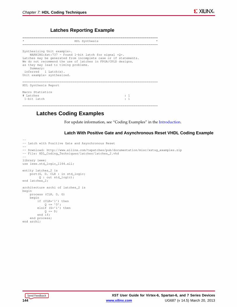
Chapter 7: HDL Coding Techniques
Latc hes Repor ting Example=========================================================================* HDL Synthesis *=========================================================================
Synthesizing Unit example>.WARNING:Xst:737 - Found 1-bit latch for signal <Q>.
Latches may be generated from incomplete case or if statements.We do not recommend the use of latches in FPGA/CPLD designs,as they may lead to timing problems.
Summary:inferred 1 Latch(s).Unit example> synthesized.
=========================================================================HDL Synthesis Report
Macro Statistics# Latches : 11-bit latch : 1
=========================================================================
Latc hes Coding ExamplesFor update information, see “Coding Examples” in the Introduction.
Latc h With Positive Gate and Async hronous Reset VHDL Coding Example---- Latch with Positive Gate and Asynchronous Reset---- Download: http://www.xilinx.com/txpatches/pub/documentation/misc/xstug_examples.zip-- File: HDL_Coding_Techniques/latches/latches_2.vhd--library ieee;use ieee.std_logic_1164.all;
entity latches_2 isport(G, D, CLR : in std_logic;
Q : out std_logic);end latches_2;
architecture archi of latches_2 isbegin
process (CLR, D, G)begin
if (CLR=’1’) thenQ <= ’0’;
elsif (G=’1’) thenQ <= D;
end if;end process;
end archi;
XST User Guide for Vir tex-6, Spar tan-6, and 7 Series Devices144 www.xilinx.com UG687 (v 14.5) March 20, 2013
Send Feedback

Chapter 7: HDL Coding Techniques
Latc h With Positive Gate Verilog Coding Example//// Latch with Positive Gate//// Download: http://www.xilinx.com/txpatches/pub/documentation/misc/xstug_examples.zip// File: HDL_Coding_Techniques/latches/latches_1.v//module v_latches_1 (G, D, Q);
input G, D;output Q;reg Q;
always @(G or D)begin
if (G)Q = D;
endendmodule
XST User Guide for Vir tex-6, Spar tan-6, and 7 Series DevicesUG687 (v 14.5) March 20, 2013 www.xilinx.com 145
Send Feedback

Chapter 7: HDL Coding Techniques
Tristates• Tristate buffers are usually modeled by:
– A signal– An if-else construct
• This applies whether the buffer drives:– An internal bus, or– An external bus on the board on which the device resides
• The signal is assigned a high impedance value in one branch of the if-else.
Coding Style Examples• Concurrent signal assignment (VHDL)
<= I when T = ’0’ else (others => ’Z’);
• Concurrent signal assignment (Verilog)
assign O = (~T) ? I : 1’bZ;
• Combinatorial process (VHDL)
process (T, I)beginif (T = ’0’) thenO <= I;
elseO <= ’Z’;
end if;end process;
• Always block (Verilog)
always @(T or I)beginif (~T)O = I;
elseO = 1’bZ;
End
Tristates ImplementationInferred tristate buffers are implemented with different device primitives when drivingan:• Internal bus (BUFT)• External pin of the circuit (OBUFT)
Tristates Related ConstraintsConvert Tristates to Logic
Tristates Repor tingTristate buffers are inferred and reported during HDL Synthesis.
XST User Guide for Vir tex-6, Spar tan-6, and 7 Series Devices146 www.xilinx.com UG687 (v 14.5) March 20, 2013
Send Feedback
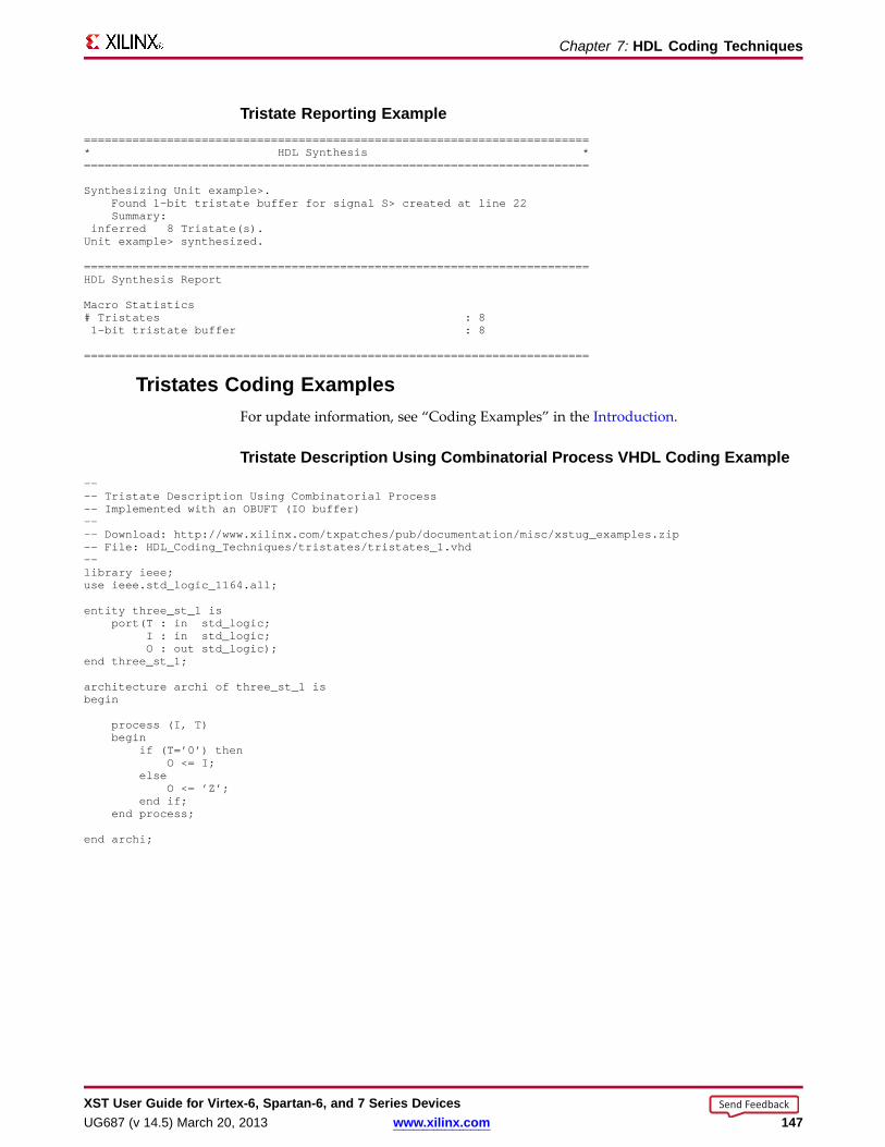
Chapter 7: HDL Coding Techniques
Tristate Repor ting Example=========================================================================* HDL Synthesis *=========================================================================
Synthesizing Unit example>.Found 1-bit tristate buffer for signal S> created at line 22Summary:
inferred 8 Tristate(s).Unit example> synthesized.
=========================================================================HDL Synthesis Report
Macro Statistics# Tristates : 81-bit tristate buffer : 8
=========================================================================
Tristates Coding ExamplesFor update information, see “Coding Examples” in the Introduction.
Tristate Description Using Combinatorial Process VHDL Coding Example---- Tristate Description Using Combinatorial Process-- Implemented with an OBUFT (IO buffer)---- Download: http://www.xilinx.com/txpatches/pub/documentation/misc/xstug_examples.zip-- File: HDL_Coding_Techniques/tristates/tristates_1.vhd--library ieee;use ieee.std_logic_1164.all;
entity three_st_1 isport(T : in std_logic;
I : in std_logic;O : out std_logic);
end three_st_1;
architecture archi of three_st_1 isbegin
process (I, T)begin
if (T=’0’) thenO <= I;
elseO <= ’Z’;
end if;end process;
end archi;
XST User Guide for Vir tex-6, Spar tan-6, and 7 Series DevicesUG687 (v 14.5) March 20, 2013 www.xilinx.com 147
Send Feedback

Chapter 7: HDL Coding Techniques
Tristate Description Using Concurrent Assignment VHDL Coding Example---- Tristate Description Using Concurrent Assignment---- Download: http://www.xilinx.com/txpatches/pub/documentation/misc/xstug_examples.zip-- File: HDL_Coding_Techniques/tristates/tristates_2.vhd--library ieee;use ieee.std_logic_1164.all;
entity three_st_2 isport(T : in std_logic;
I : in std_logic;O : out std_logic);
end three_st_2;
architecture archi of three_st_2 isbegin
O <= I when (T=’0’) else ’Z’;end archi;
Tristate Description Using Combinatorial Process VHDL Coding Example---- Tristate Description Using Combinatorial Process-- Implemented with an OBUF (internal buffer)---- Download: http://www.xilinx.com/txpatches/pub/documentation/misc/xstug_examples.zip-- File: HDL_Coding_Techniques/tristates/tristates_3.vhd--library ieee;use ieee.std_logic_1164.all;
entity example is
generic (WIDTH : integer := 8
);port(
T : in std_logic;I : in std_logic_vector(WIDTH-1 downto 0);O : out std_logic_vector(WIDTH-1 downto 0));
end example;
architecture archi of example is
signal S : std_logic_vector(WIDTH-1 downto 0);
begin
process (I, T)begin
if (T = ’1’) thenS <= I;
elseS <= (others => ’Z’);
end if;end process;
O <= not(S);
end archi;
XST User Guide for Vir tex-6, Spar tan-6, and 7 Series Devices148 www.xilinx.com UG687 (v 14.5) March 20, 2013
Send Feedback

Chapter 7: HDL Coding Techniques
Tristate Description Using Combinatorial Always Bloc k Verilog CodingExample
//// Tristate Description Using Combinatorial Always Block//// Download: http://www.xilinx.com/txpatches/pub/documentation/misc/xstug_examples.zip// File: HDL_Coding_Techniques/tristates/tristates_1.v//module v_three_st_1 (T, I, O);
input T, I;output O;reg O;
always @(T or I)begin
if (~T)O = I;
elseO = 1’bZ;
end
endmodule
Tristate Description Using Concurrent Assignment Verilog Coding Example//// Tristate Description Using Concurrent Assignment//// Download: http://www.xilinx.com/txpatches/pub/documentation/misc/xstug_examples.zip// File: HDL_Coding_Techniques/tristates/tristates_2.v//module v_three_st_2 (T, I, O);
input T, I;output O;
assign O = (~T) ? I: 1’bZ;
endmodule
XST User Guide for Vir tex-6, Spar tan-6, and 7 Series DevicesUG687 (v 14.5) March 20, 2013 www.xilinx.com 149
Send Feedback
Chapter 7: HDL Coding Techniques
Counter s and Accum ulator sXST provides inference capability for Counters and Accumulators.
• You can describe additional optional features, such as:
– Asynchronous set, reset, or load
– Synchronous set, reset, or load
– Clock enable
– Up, down, or up/down direction
• A Counter is also known as an Incrementer or Decrementer.
• XST supports the description of both signed and unsigned Counters andAccumulators.
Accum ulator Compared to CounterAn Accumulator differs from a Counter in the nature of the operands of the add orsubtract operation, or both.
Counter Description
• The destination and first operand is a signal or variable.
• The other operand is a constant equal to 1.
A <= A + 1;
Accumulator Description
• The destination and first operand is a signal or variable.
• The second operand is either:
– A signal or variable
A <= A + B;
– A constant not equal to 1
A <= A + Constant;
Direction of Inferred Counter or Accum ulator• The direction of an inferred Counter or Accumulator is:
– up
– down
– updown
• For an updown Accumulator, the accumulated data can differ between the up anddown mode.
if updown = ’1’ thena <= a + b;
elsea <= a - c;
end if;
XST User Guide for Vir tex-6, Spar tan-6, and 7 Series Devices150 www.xilinx.com UG687 (v 14.5) March 20, 2013
Send Feedback
Chapter 7: HDL Coding Techniques
Number of Bits• XST determines the minimum number of bits needed to implement an inferred
Counter or Accumulator whether it is described with:
– A signal of type integer, or
– An array of bits
• Unless otherwise specified in the HDL description, a Counter can take all valuesallowed by this number during circuit.
• You can count up to a specific value using a modulo operator. See the followingsyntax examples.
VHDL Syntax Examplecnt <= (cnt + 1) mod MAX ;
Verilog Syntax Examplecnt <= (cnt + 1) %MAX;
Counter s and Accum ulator s Implementation• Implement Counters and Accumulators on:
– Slice logic
– DSP block resources
• A DSP block can absorb up to two levels of Registers.
– The Counter or Accumulator must fit on a single DSP block.
– If the Counter or Accumulator macro does not fit on a single DSP block, XSTimplements the entire macro using slice logic.
• Macro implementation on DSP block resources is controlled by Use DSP Block witha default value of auto.
• In auto mode, XST implements Counters and Accumulators considering suchfactors as:
– DSP block resources available on the device.
– Contextual information such as the source of the data being accumulated.
– Whether implementation in a DSP block allows the leveraging of thehigh-performance cascading capabilities of the DSP blocks.
• For most standalone Counters and Accumulators, slice logic is favored by default inautomode. Change it to yes in order to force implementation onto DSP blocks.
• In auto mode, DSP Utilization Ratio controls DSP block resource utilization. XSTtries to utilize all available DSP block resources.
• For more information, see Arithmetic Operators DSP Block Resources.
XST User Guide for Vir tex-6, Spar tan-6, and 7 Series DevicesUG687 (v 14.5) March 20, 2013 www.xilinx.com 151
Send Feedback

Chapter 7: HDL Coding Techniques
Counter s and Accum ulator s Related Constraints• Use DSP Block
• DSP Utilization Ratio
Counter s and Accum ulator s Repor tingCounters and Accumulators are identified during Advanced HDL Synthesis by acombination of:
• A Register, and
• An Adder/Subtractor macro previously inferred during HDL Synthesis
Counter s and Accum ulator s Repor ting Example=========================================================================* HDL Synthesis *=========================================================================
Synthesizing Unit <example>.Found 4-bit register for signal <cnt>.Found 4-bit register for signal <acc>.Found 4-bit adder for signal <n0005> created at line 29.Found 4-bit adder for signal <n0006> created at line 30.Summary:
inferred 2 Adder/Subtractor(s).inferred 8 D-type flip-flop(s).Unit <example> synthesized.
=========================================================================HDL Synthesis Report
Macro Statistics# Adders/Subtractors : 24-bit adder : 2# Registers : 24-bit register : 2
=========================================================================
=========================================================================* Advanced HDL Synthesis *=========================================================================
Synthesizing (advanced) Unit <example>.The following registers are absorbed into counter <cnt>: 1 register on signal <cnt>.The following registers are absorbed into accumulator <acc>: 1 register on signal <acc>.Unit <example> synthesized (advanced).
=========================================================================Advanced HDL Synthesis Report
Macro Statistics# Counters : 14-bit up counter : 1# Accumulators : 14-bit up accumulator : 1
=========================================================================
Counter s and Accum ulator s Coding ExamplesFor update information, see “Coding Examples” in the Introduction.
XST User Guide for Vir tex-6, Spar tan-6, and 7 Series Devices152 www.xilinx.com UG687 (v 14.5) March 20, 2013
Send Feedback
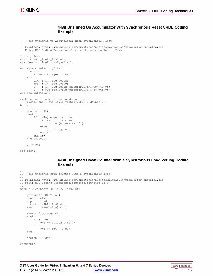
Chapter 7: HDL Coding Techniques
4-Bit Unsigned Up Accum ulator With Synchronous Reset VHDL CodingExample
---- 4-bit Unsigned Up Accumulator with synchronous Reset---- Download: http://www.xilinx.com/txpatches/pub/documentation/misc/xstug_examples.zip-- File: HDL_Coding_Techniques/accumulators/accumulators_2.vhd--library ieee;use ieee.std_logic_1164.all;use ieee.std_logic_unsigned.all;
entity accumulators_2 isgeneric (
WIDTH : integer := 4);port (
clk : in std_logic;rst : in std_logic;D : in std_logic_vector(WIDTH-1 downto 0);Q : out std_logic_vector(WIDTH-1 downto 0));
end accumulators_2;
architecture archi of accumulators_2 issignal cnt : std_logic_vector(WIDTH-1 downto 0);
begin
process (clk)begin
if rising_edge(clk) thenif (rst = ’1’) then
cnt <= (others => ’0’);else
cnt <= cnt + D;end if;
end if;end process;
Q <= cnt;
end archi;
4-Bit Unsigned Down Counter With a Synchronous Load Verilog CodingExample
//// 4-bit unsigned down counter with a synchronous load.//// Download: http://www.xilinx.com/txpatches/pub/documentation/misc/xstug_examples.zip// File: HDL_Coding_Techniques/counters/counters_31.v//module v_counters_31 (clk, load, Q);
parameter WIDTH = 4;input clk;input load;output [WIDTH-1:0] Q;reg [WIDTH-1:0] cnt;
always @(posedge clk)begin
if (load)cnt <= {WIDTH{1’b1}};
elsecnt <= cnt - 1’b1;
end
assign Q = cnt;
endmodule
XST User Guide for Vir tex-6, Spar tan-6, and 7 Series DevicesUG687 (v 14.5) March 20, 2013 www.xilinx.com 153
Send Feedback

Chapter 7: HDL Coding Techniques
Shift Register sA Shift Register is a chain of Flip-Flops allowing propagation of data across a fixed(static) number of latency stages. In contrast, in Dynamic Shift Registers, the length ofthe propagation chain varies dynamically during circuit operation.
Static Shift Register ElementsA static Shift Register usually involves:
• A clock
• An optional clock enable
• A serial data input
• A serial data output
Including Additional Functionality• You can include additional functionality, such as reset, set, or parallel load logic.
• If you include additional functionality, XST may not be able to take advantageof dedicated SRL-type primitives for reduced device utilization and optimizedperformance.
• Xilinx® recommends that you remove such logic and load the contents serially.
Describing Shift Register sThe following coding examples show two methods for describing the core functionalityof a Shift Register.
Concatenation Operator VHDL Coding ExampleThis coding example uses a concatenation operator to compactly describe the corefunctionality of a Shift Register.
shreg <= shreg (6 downto 0) & SI;
For Loop VHDL Coding ExampleThis coding example uses a for loop construct to describe the core functionality of aShift Register.
for i in 0 to 6 loopshreg(i+1) <= shreg(i);
end loop;shreg(0) <= SI;
XST User Guide for Vir tex-6, Spar tan-6, and 7 Series Devices154 www.xilinx.com UG687 (v 14.5) March 20, 2013
Send Feedback

Chapter 7: HDL Coding Techniques
Shift Register s ImplementationShift Registers Implementation includes:
• Shift Registers SRL-Based Implementation
• Implementing Shift Registers on Block RAM
• Implementing Shift Registers on LUT RAM
Shift Register s SRL-Based Implementation• XST implements inferred Shift Registers on SRL-type resources such as:
– SRL16
– SRL16E
– SRLC16
– SRLC16E
– SRLC32E
• Depending on the length of the Shift Register, XST either:
– Implements it on a single SRL-type primitive, or
– Takes advantage of the cascading capability of SRLC-type primitives.
• XST also tries to take advantage of this cascading capability if the rest of the designuses some intermediate positions of the Shift Register.
• You can implement delay lines on RAM resources (block RAM or LUT RAM)instead of SRL-type resources. Implementing delay lines on RAM resources canbring significant benefits, especially with respect to power savings, when delaylines become relatively long.
• XST cannot implement a Shift Register on block RAM or LUT RAM resources asoutlined in Describing Shift Registers. You must explicitly describe the RAM-basedimplementation. See the following coding examples.
Implementing Shift Register s on Bloc k RAM• Read-first synchronization mode includes a Counter that:
– Sequentially scans the addressable space.
– Counts back to zero when reaching the delay line length minus two.
• To ensure maximum performance, use the block RAM output Latch and optionaloutput Register stage. For example:
– A 512-deep delay line uses 510 addressable data words in the RAM.
– The data output Latch and optional output Register provide the last two stages.
• For more information, see RAM HDL Coding Guidelines.
XST User Guide for Vir tex-6, Spar tan-6, and 7 Series DevicesUG687 (v 14.5) March 20, 2013 www.xilinx.com 155
Send Feedback
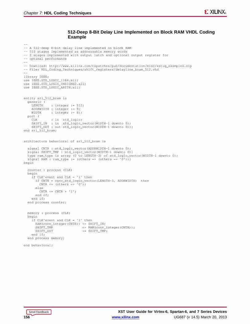
Chapter 7: HDL Coding Techniques
512-Deep 8-Bit Delay Line Implemented on Bloc k RAM VHDL CodingExample
---- A 512-deep 8-bit delay line implemented on block RAM-- 510 stages implemented as addressable memory words-- 2 stages implemented with output latch and optional output register for-- optimal performance---- Download: http://www.xilinx.com/txpatches/pub/documentation/misc/xstug_examples.zip-- File: HDL_Coding_Techniques/shift_registers/delayline_bram_512.vhd--library IEEE;use IEEE.STD_LOGIC_1164.all;use IEEE.STD_LOGIC_UNSIGNED.all;use IEEE.STD_LOGIC_ARITH.all;
entity srl_512_bram isgeneric (LENGTH : integer := 512;ADDRWIDTH: integer := 9;WIDTH : integer := 8);
port (CLK : in std_logic;SHIFT_IN : in std_logic_vector(WIDTH-1 downto 0);SHIFT_OUT : out std_logic_vector(WIDTH-1 downto 0));
end srl_512_bram;
architecture behavioral of srl_512_bram is
signal CNTR : std_logic_vector(ADDRWIDTH-1 downto 0);signal SHIFT_TMP : std_logic_vector(WIDTH-1 downto 0);type ram_type is array (0 to LENGTH-3) of std_logic_vector(WIDTH-1 downto 0);signal RAM : ram_type := (others => (others => ’0’));
begin
counter : process (CLK)beginif CLK’event and CLK = ’1’ thenif CNTR = conv_std_logic_vector(LENGTH-3, ADDRWIDTH) thenCNTR <= (others => ’0’);
elseCNTR <= CNTR + ’1’;
end if;end if;
end process counter;
memory : process (CLK)beginif CLK’event and CLK = ’1’ thenRAM(conv_integer(CNTR)) <= SHIFT_IN;SHIFT_TMP <= RAM(conv_integer(CNTR));SHIFT_OUT <= SHIFT_TMP;
end if;end process memory;
end behavioral;
XST User Guide for Vir tex-6, Spar tan-6, and 7 Series Devices156 www.xilinx.com UG687 (v 14.5) March 20, 2013
Send Feedback
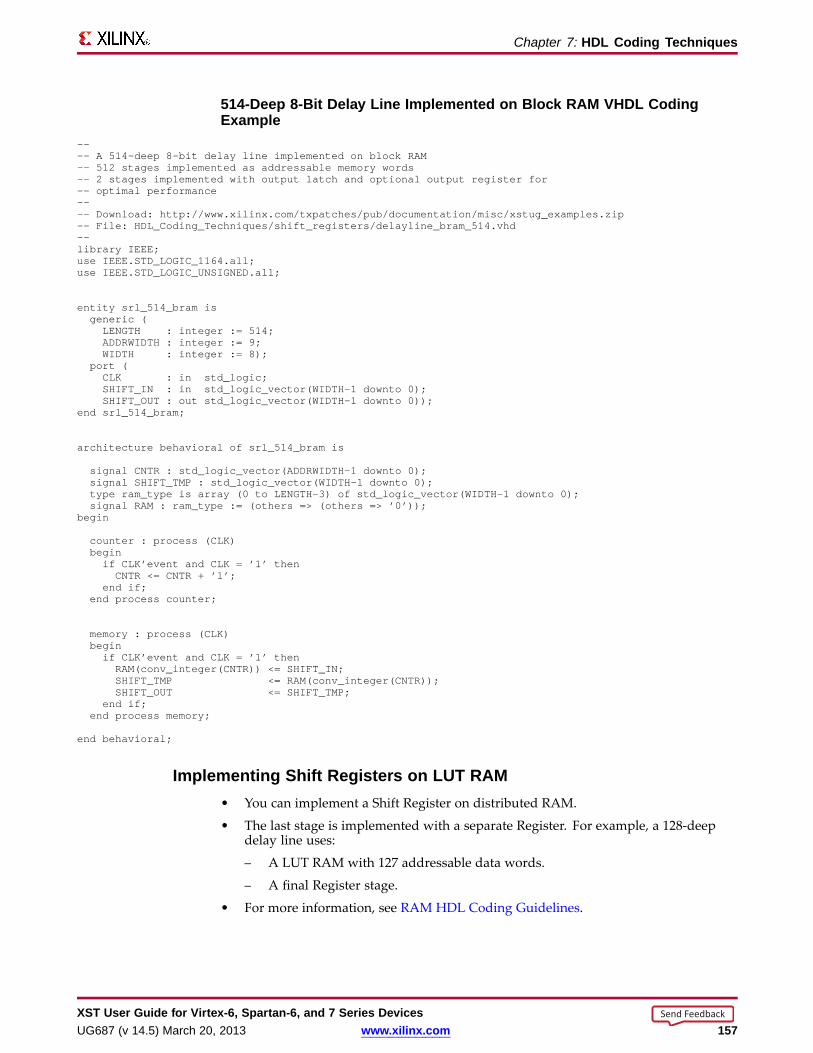
Chapter 7: HDL Coding Techniques
514-Deep 8-Bit Delay Line Implemented on Bloc k RAM VHDL CodingExample
---- A 514-deep 8-bit delay line implemented on block RAM-- 512 stages implemented as addressable memory words-- 2 stages implemented with output latch and optional output register for-- optimal performance---- Download: http://www.xilinx.com/txpatches/pub/documentation/misc/xstug_examples.zip-- File: HDL_Coding_Techniques/shift_registers/delayline_bram_514.vhd--library IEEE;use IEEE.STD_LOGIC_1164.all;use IEEE.STD_LOGIC_UNSIGNED.all;
entity srl_514_bram isgeneric (LENGTH : integer := 514;ADDRWIDTH: integer := 9;WIDTH : integer := 8);
port (CLK : in std_logic;SHIFT_IN : in std_logic_vector(WIDTH-1 downto 0);SHIFT_OUT : out std_logic_vector(WIDTH-1 downto 0));
end srl_514_bram;
architecture behavioral of srl_514_bram is
signal CNTR : std_logic_vector(ADDRWIDTH-1 downto 0);signal SHIFT_TMP : std_logic_vector(WIDTH-1 downto 0);type ram_type is array (0 to LENGTH-3) of std_logic_vector(WIDTH-1 downto 0);signal RAM : ram_type := (others => (others => ’0’));
begin
counter : process (CLK)beginif CLK’event and CLK = ’1’ thenCNTR <= CNTR + ’1’;
end if;end process counter;
memory : process (CLK)beginif CLK’event and CLK = ’1’ thenRAM(conv_integer(CNTR)) <= SHIFT_IN;SHIFT_TMP <= RAM(conv_integer(CNTR));SHIFT_OUT <= SHIFT_TMP;
end if;end process memory;
end behavioral;
Implementing Shift Register s on LUT RAM• You can implement a Shift Register on distributed RAM.
• The last stage is implemented with a separate Register. For example, a 128-deepdelay line uses:
– A LUT RAM with 127 addressable data words.
– A final Register stage.
• For more information, see RAM HDL Coding Guidelines.
XST User Guide for Vir tex-6, Spar tan-6, and 7 Series DevicesUG687 (v 14.5) March 20, 2013 www.xilinx.com 157
Send Feedback
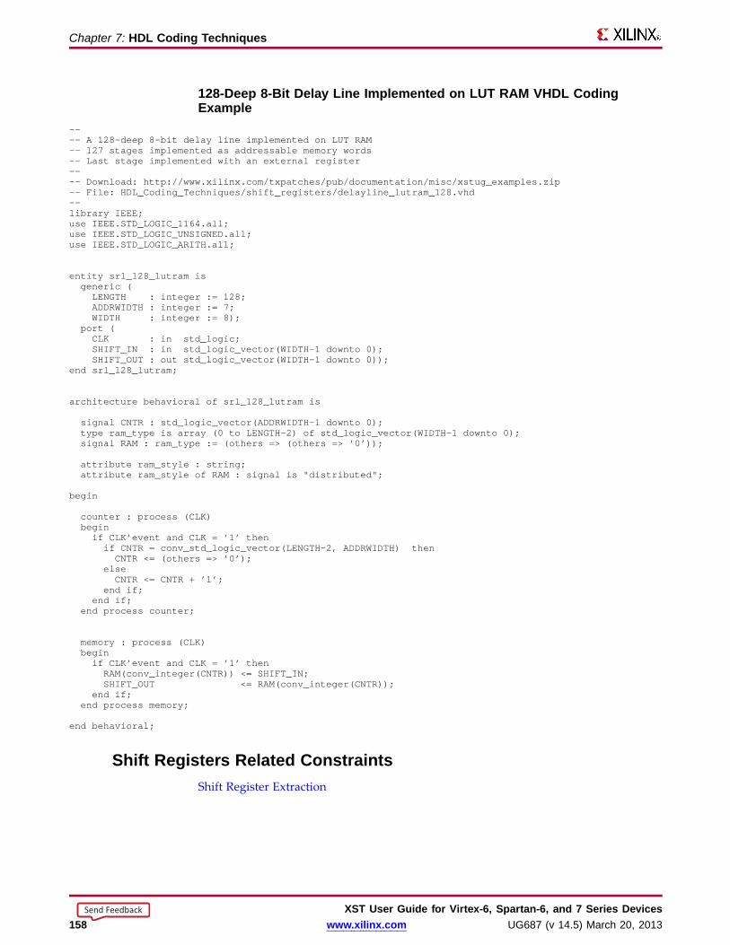
Chapter 7: HDL Coding Techniques
128-Deep 8-Bit Delay Line Implemented on LUT RAM VHDL CodingExample
---- A 128-deep 8-bit delay line implemented on LUT RAM-- 127 stages implemented as addressable memory words-- Last stage implemented with an external register---- Download: http://www.xilinx.com/txpatches/pub/documentation/misc/xstug_examples.zip-- File: HDL_Coding_Techniques/shift_registers/delayline_lutram_128.vhd--library IEEE;use IEEE.STD_LOGIC_1164.all;use IEEE.STD_LOGIC_UNSIGNED.all;use IEEE.STD_LOGIC_ARITH.all;
entity srl_128_lutram isgeneric (LENGTH : integer := 128;ADDRWIDTH: integer := 7;WIDTH : integer := 8);
port (CLK : in std_logic;SHIFT_IN : in std_logic_vector(WIDTH-1 downto 0);SHIFT_OUT : out std_logic_vector(WIDTH-1 downto 0));
end srl_128_lutram;
architecture behavioral of srl_128_lutram is
signal CNTR : std_logic_vector(ADDRWIDTH-1 downto 0);type ram_type is array (0 to LENGTH-2) of std_logic_vector(WIDTH-1 downto 0);signal RAM : ram_type := (others => (others => ’0’));
attribute ram_style : string;attribute ram_style of RAM : signal is "distributed";
begin
counter : process (CLK)beginif CLK’event and CLK = ’1’ thenif CNTR = conv_std_logic_vector(LENGTH-2, ADDRWIDTH) thenCNTR <= (others => ’0’);
elseCNTR <= CNTR + ’1’;
end if;end if;
end process counter;
memory : process (CLK)beginif CLK’event and CLK = ’1’ thenRAM(conv_integer(CNTR)) <= SHIFT_IN;SHIFT_OUT <= RAM(conv_integer(CNTR));
end if;end process memory;
end behavioral;
Shift Register s Related ConstraintsShift Register Extraction
XST User Guide for Vir tex-6, Spar tan-6, and 7 Series Devices158 www.xilinx.com UG687 (v 14.5) March 20, 2013
Send Feedback
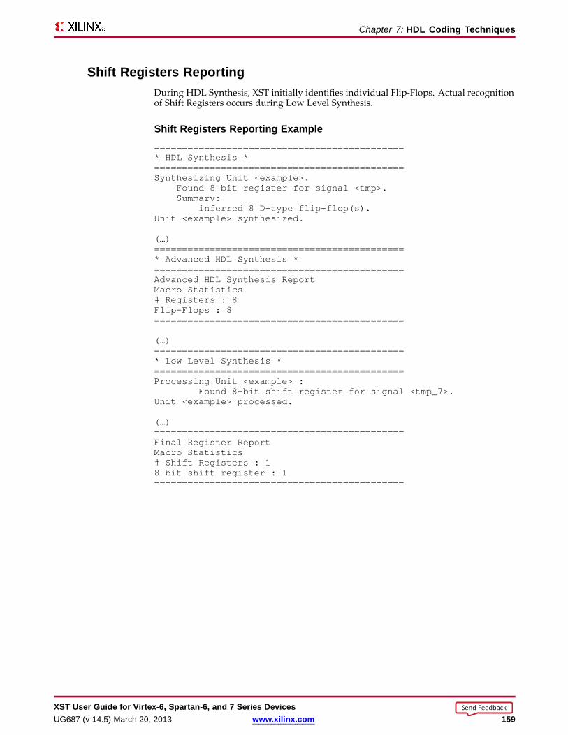
Chapter 7: HDL Coding Techniques
Shift Register s Repor tingDuring HDL Synthesis, XST initially identifies individual Flip-Flops. Actual recognitionof Shift Registers occurs during Low Level Synthesis.
Shift Register s Repor ting Example=============================================* HDL Synthesis *=============================================Synthesizing Unit <example>.
Found 8-bit register for signal <tmp>.Summary:
inferred 8 D-type flip-flop(s).Unit <example> synthesized.
(…)=============================================* Advanced HDL Synthesis *=============================================Advanced HDL Synthesis ReportMacro Statistics# Registers : 8Flip-Flops : 8=============================================
(…)=============================================* Low Level Synthesis *=============================================Processing Unit <example> :
Found 8-bit shift register for signal <tmp_7>.Unit <example> processed.
(…)=============================================Final Register ReportMacro Statistics# Shift Registers : 18-bit shift register : 1=============================================
XST User Guide for Vir tex-6, Spar tan-6, and 7 Series DevicesUG687 (v 14.5) March 20, 2013 www.xilinx.com 159
Send Feedback
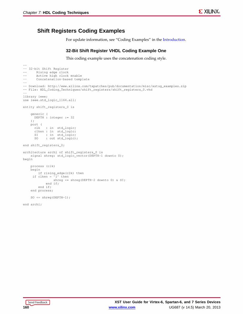
Chapter 7: HDL Coding Techniques
Shift Register s Coding ExamplesFor update information, see “Coding Examples” in the Introduction.
32-Bit Shift Register VHDL Coding Example OneThis coding example uses the concatenation coding style.
---- 32-bit Shift Register-- Rising edge clock-- Active high clock enable-- Concatenation-based template---- Download: http://www.xilinx.com/txpatches/pub/documentation/misc/xstug_examples.zip-- File: HDL_Coding_Techniques/shift_registers/shift_registers_0.vhd--library ieee;use ieee.std_logic_1164.all;
entity shift_registers_0 is
generic (DEPTH : integer := 32
);port (clk : in std_logic;clken : in std_logic;SI : in std_logic;SO : out std_logic);
end shift_registers_0;
architecture archi of shift_registers_0 issignal shreg: std_logic_vector(DEPTH-1 downto 0);
begin
process (clk)begin
if rising_edge(clk) thenif clken = ’1’ then
shreg <= shreg(DEPTH-2 downto 0) & SI;end if;
end if;end process;
SO <= shreg(DEPTH-1);
end archi;
XST User Guide for Vir tex-6, Spar tan-6, and 7 Series Devices160 www.xilinx.com UG687 (v 14.5) March 20, 2013
Send Feedback
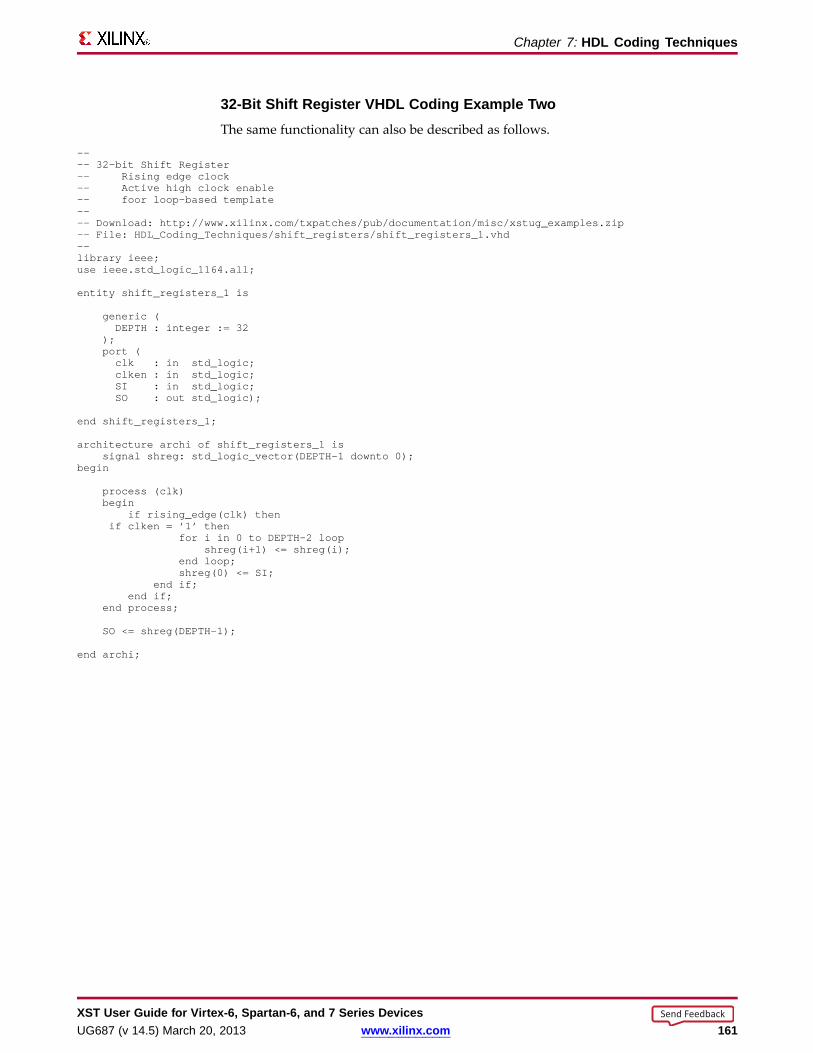
Chapter 7: HDL Coding Techniques
32-Bit Shift Register VHDL Coding Example TwoThe same functionality can also be described as follows.
---- 32-bit Shift Register-- Rising edge clock-- Active high clock enable-- foor loop-based template---- Download: http://www.xilinx.com/txpatches/pub/documentation/misc/xstug_examples.zip-- File: HDL_Coding_Techniques/shift_registers/shift_registers_1.vhd--library ieee;use ieee.std_logic_1164.all;
entity shift_registers_1 is
generic (DEPTH : integer := 32
);port (clk : in std_logic;clken : in std_logic;SI : in std_logic;SO : out std_logic);
end shift_registers_1;
architecture archi of shift_registers_1 issignal shreg: std_logic_vector(DEPTH-1 downto 0);
begin
process (clk)begin
if rising_edge(clk) thenif clken = ’1’ then
for i in 0 to DEPTH-2 loopshreg(i+1) <= shreg(i);
end loop;shreg(0) <= SI;
end if;end if;
end process;
SO <= shreg(DEPTH-1);
end archi;
XST User Guide for Vir tex-6, Spar tan-6, and 7 Series DevicesUG687 (v 14.5) March 20, 2013 www.xilinx.com 161
Send Feedback

Chapter 7: HDL Coding Techniques
8-Bit Shift Register Verilog Coding Example OneThis coding example uses a concatenation to describe the Register chain.
//// 8-bit Shift Register// Rising edge clock// Active high clock enable// Concatenation-based template//// Download: http://www.xilinx.com/txpatches/pub/documentation/misc/xstug_examples.zip// File: HDL_Coding_Techniques/shift_registers/shift_registers_0.v//module v_shift_registers_0 (clk, clken, SI, SO);
parameter WIDTH = 8;input clk, clken, SI;output SO;reg [WIDTH-1:0] shreg;
always @(posedge clk)begin
if (clken)shreg = {shreg[WIDTH-2:0], SI};
end
assign SO = shreg[WIDTH-1];
endmodule
8-Bit Shift Register Verilog Coding Example Two//// 8-bit Shift Register// Rising edge clock// Active high clock enable// For-loop based template//// Download: http://www.xilinx.com/txpatches/pub/documentation/misc/xstug_examples.zip// File: HDL_Coding_Techniques/shift_registers/shift_registers_1.v//module v_shift_registers_1 (clk, clken, SI, SO);
parameter WIDTH = 8;input clk, clken, SI;output SO;reg [WIDTH-1:0] shreg;
integer i;
always @(posedge clk)begin
if (clken)begin
for (i = 0; i < WIDTH-1; i = i+1)shreg[i+1] <= shreg[i];
shreg[0] <= SI;end
end
assign SO = shreg[WIDTH-1];
endmodule
XST User Guide for Vir tex-6, Spar tan-6, and 7 Series Devices162 www.xilinx.com UG687 (v 14.5) March 20, 2013
Send Feedback

Chapter 7: HDL Coding Techniques
Dynamic Shift Register s• ADynamic Shift Register is a Shift Register the length of which can vary dynamically
during circuit operation.
• A Dynamic Shift Register can be seen as:
– A chain of Flip-Flops of the maximum length that it can accept during circuitoperation.
– A Multiplexer that selects, in a given clock cycle, the stage at which data is to beextracted from the propagation chain.
• XST can infer Dynamic Shift Registers of any maximal length.
• XST can implement Dynamic Shift Registers optimally using the SRL-type primitivesavailable in the device family.
Dynamic Shift Register s Diagram
Dynamic Shift Register s Related ConstraintsShift Register Extraction
Dynamic Shift Register s Repor ting• XST identifies Flip-Flops and Multiplexers during HDL Synthesis.
• During Advanced HDL Synthesis:
– XST identifies Dynamic Shift Registers.
– XST determines the dependency between the Flip-Flops and Multiplexers.
XST User Guide for Vir tex-6, Spar tan-6, and 7 Series DevicesUG687 (v 14.5) March 20, 2013 www.xilinx.com 163
Send Feedback
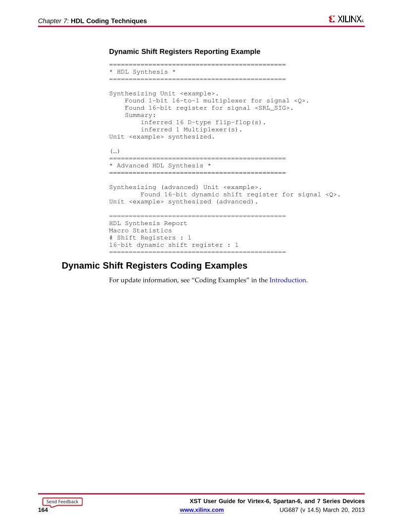
Chapter 7: HDL Coding Techniques
Dynamic Shift Register s Repor ting Example=============================================* HDL Synthesis *=============================================
Synthesizing Unit <example>.Found 1-bit 16-to-1 multiplexer for signal <Q>.Found 16-bit register for signal <SRL_SIG>.Summary:
inferred 16 D-type flip-flop(s).inferred 1 Multiplexer(s).
Unit <example> synthesized.
(…)=============================================* Advanced HDL Synthesis *=============================================
Synthesizing (advanced) Unit <example>.Found 16-bit dynamic shift register for signal <Q>.
Unit <example> synthesized (advanced).
=============================================HDL Synthesis ReportMacro Statistics# Shift Registers : 116-bit dynamic shift register : 1=============================================
Dynamic Shift Register s Coding ExamplesFor update information, see “Coding Examples” in the Introduction.
XST User Guide for Vir tex-6, Spar tan-6, and 7 Series Devices164 www.xilinx.com UG687 (v 14.5) March 20, 2013
Send Feedback

Chapter 7: HDL Coding Techniques
32-Bit Dynamic Shift Register s VHDL Coding Example---- 32-bit dynamic shift register.---- Download: http://www.xilinx.com/txpatches/pub/documentation/misc/xstug_examples.zip-- File: HDL_Coding_Techniques/dynamic_shift_registers/dynamic_shift_registers_1.vhd--library IEEE;use IEEE.std_logic_1164.all;use IEEE.std_logic_unsigned.all;
entity example is
generic (DEPTH : integer := 32;SEL_WIDTH : integer := 5
);port(
CLK : in std_logic;SI : in std_logic;CE : in std_logic;A : in std_logic_vector(SEL_WIDTH-1 downto 0);DO : out std_logic
);
end example;
architecture rtl of example is
type SRL_ARRAYis array (0 to DEPTH-1) of std_logic;-- The type SRL_ARRAYcan be array-- (0 to DEPTH-1) of-- std_logic_vector(BUS_WIDTH downto 0)-- or array (DEPTH-1 downto 0) of-- std_logic_vector(BUS_WIDTH downto 0)-- (the subtype is forward (see below))signal SRL_SIG : SRL_ARRAY;
beginprocess (CLK)begin
if rising_edge(CLK) thenif CE = ’1’ then
SRL_SIG <= SI & SRL_SIG(0 to DEPTH-2);end if;
end if;end process;
DO <= SRL_SIG(conv_integer(A));
end rtl;
XST User Guide for Vir tex-6, Spar tan-6, and 7 Series DevicesUG687 (v 14.5) March 20, 2013 www.xilinx.com 165
Send Feedback
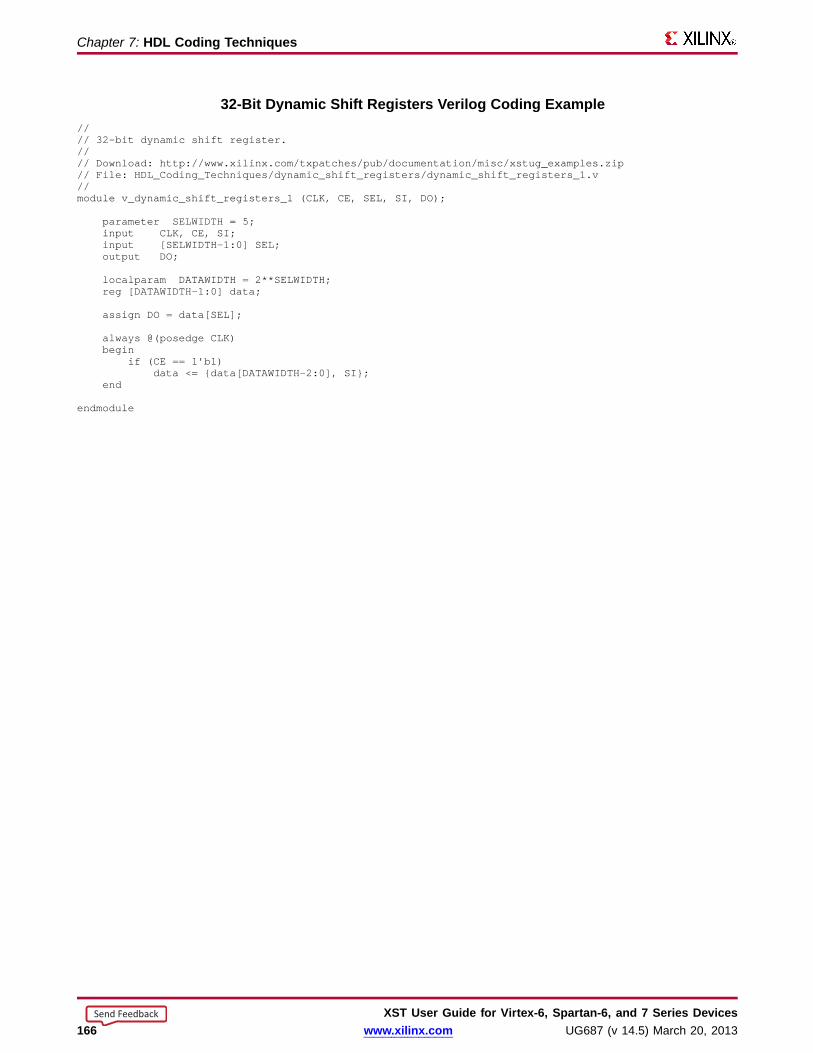
Chapter 7: HDL Coding Techniques
32-Bit Dynamic Shift Register s Verilog Coding Example//// 32-bit dynamic shift register.//// Download: http://www.xilinx.com/txpatches/pub/documentation/misc/xstug_examples.zip// File: HDL_Coding_Techniques/dynamic_shift_registers/dynamic_shift_registers_1.v//module v_dynamic_shift_registers_1 (CLK, CE, SEL, SI, DO);
parameter SELWIDTH = 5;input CLK, CE, SI;input [SELWIDTH-1:0] SEL;output DO;
localparam DATAWIDTH= 2**SELWIDTH;reg [DATAWIDTH-1:0] data;
assign DO = data[SEL];
always @(posedge CLK)begin
if (CE == 1’b1)data <= {data[DATAWIDTH-2:0], SI};
end
endmodule
XST User Guide for Vir tex-6, Spar tan-6, and 7 Series Devices166 www.xilinx.com UG687 (v 14.5) March 20, 2013
Send Feedback

Chapter 7: HDL Coding Techniques
Multiple xers• Multiplexer macros can be inferred from different coding styles, involving either:
– Concurrent assignments, or
– Description in combinatorial processes or always blocks, or– Descriptions within sequential processes or always blocks
• Descriptions of Multiplexers usually involve:
– if-elsif constructs– case constructs
• When using a case statement, make sure that:– All selector values are enumerated, or
– A default statement defines which data is selected for selector values that arenot explicitly enumerated.
• Failing to do so creates undesired Latches. If the Multiplexer is described with anif-elsif construct, a missing else can also create undesired Latches.
• When the same data is to be selected for different values of the selector, use don’tcare to compactly describe those selector values.
Multiple xers ImplementationThe decision to explicitly infer a Multiplexer macro may depend on the nature of theMultiplexer inputs, especially the number of common inputs.
Multiple xers Verilog Case Implementation Style Parameter• Use a Case Implementation Style Parameter to further specify a case statement.• Specifying full, parallel, or full-parallel can cause the implementation to behave
differently from the initial model.
• For more information, see Chapter 9, Design Constraints.
Case Implementation Style Parameter Values• none (default)
XST implements the behavior of the case statement as written.• full
– XST considers that case statements are complete.
– XST avoids latch creation, even if not all possible selector values are enumerated.
• parallel
– XST considers that the branches cannot occur simultaneously.
– XST does not create priority encoding logic.
• full-parallel
– XST considers that case statements are complete, and that the branches cannotoccur simultaneously.
– XST avoids latch creation and priority encoding logic.
XST User Guide for Vir tex-6, Spar tan-6, and 7 Series DevicesUG687 (v 14.5) March 20, 2013 www.xilinx.com 167
Send Feedback
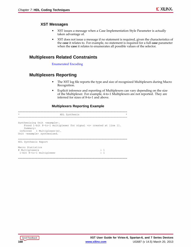
Chapter 7: HDL Coding Techniques
XST Messages• XST issues a message when a Case Implementation Style Parameter is actually
taken advantage of.
• XST does not issue a message if no statement is required, given the characteristics ofthe case it relates to. For example, no statement is required for a full case parameterwhen the case it relates to enumerates all possible values of the selector.
Multiple xers Related ConstraintsEnumerated Encoding
Multiple xers Repor ting• The XST log file reports the type and size of recognized Multiplexers during Macro
Recognition.
• Explicit inference and reporting of Multiplexers can vary depending on the sizeof the Multiplexer. For example, 4-to-1 Multiplexers are not reported. They areinferred for sizes of 8-to-1 and above.
Multiple xers Repor ting Example=========================================================================* HDL Synthesis *=========================================================================
Synthesizing Unit <example>.Found 1-bit 8-to-1 multiplexer for signal <o> created at line 11.Summary:
inferred 1 Multiplexer(s).Unit <example> synthesized.
=========================================================================HDL Synthesis Report
Macro Statistics# Multiplexers : 11-bit 8-to-1 multiplexer : 1
=========================================================================
XST User Guide for Vir tex-6, Spar tan-6, and 7 Series Devices168 www.xilinx.com UG687 (v 14.5) March 20, 2013
Send Feedback

Chapter 7: HDL Coding Techniques
Multiple xers Coding ExamplesFor update information, see “Coding Examples” in the Introduction.
8-to-1 1-Bit MUX Using an If Statement VHDL Coding Example//// 8-to-1 1-bit MUXusing an If statement.//// Download: http://www.xilinx.com/txpatches/pub/documentation/misc/xstug_examples.zip// File: HDL_Coding_Techniques/multiplexers/multiplexers_1.v//module v_multiplexers_1 (di, sel, do);
input [7:0] di;input [2:0] sel;output reg do;
always @(sel or di)begin
if (sel == 3’b000) do = di[7];else if (sel == 3’b001) do = di[6];else if (sel == 3’b010) do = di[5];else if (sel == 3’b011) do = di[4];else if (sel == 3’b100) do = di[3];else if (sel == 3’b101) do = di[2];else if (sel == 3’b110) do = di[1];else do = di[0];
endendmodule
8-to-1 1-Bit MUX Using an If Statement Verilog Coding Example//// 8-to-1 1-bit MUXusing an If statement.//// Download: http://www.xilinx.com/txpatches/pub/documentation/misc/xstug_examples.zip// File: HDL_Coding_Techniques/multiplexers/multiplexers_1.v//module v_multiplexers_1 (di, sel, do);
input [7:0] di;input [2:0] sel;output reg do;
always @(sel or di)begin
if (sel == 3’b000) do = di[7];else if (sel == 3’b001) do = di[6];else if (sel == 3’b010) do = di[5];else if (sel == 3’b011) do = di[4];else if (sel == 3’b100) do = di[3];else if (sel == 3’b101) do = di[2];else if (sel == 3’b110) do = di[1];else do = di[0];
endendmodule
XST User Guide for Vir tex-6, Spar tan-6, and 7 Series DevicesUG687 (v 14.5) March 20, 2013 www.xilinx.com 169
Send Feedback

Chapter 7: HDL Coding Techniques
8-to-1 1-Bit MUX Using a Case Statement VHDL Coding Example---- 8-to-1 1-bit MUXusing a Case statement.---- Download: http://www.xilinx.com/txpatches/pub/documentation/misc/xstug_examples.zip-- File: HDL_Coding_Techniques/multiplexers/multiplexers_2.vhd--library ieee;use ieee.std_logic_1164.all;
entity multiplexers_2 is
port (di : in std_logic_vector(7 downto 0);sel : in std_logic_vector(2 downto 0);do : out std_logic);
end multiplexers_2;
architecture archi of multiplexers_2 isbegin
process (sel, di)begin
case sel iswhen "000" => do <= di(7);when "001" => do <= di(6);when "010" => do <= di(5);when "011" => do <= di(4);when "100" => do <= di(3);when "101" => do <= di(2);when "110" => do <= di(1);when others => do <= di(0);
end case;end process;
end archi;
8-to-1 1-Bit MUX Using a Case Statement Verilog Coding Example//// 8-to-1 1-bit MUXusing a Case statement.//// Download: http://www.xilinx.com/txpatches/pub/documentation/misc/xstug_examples.zip// File: HDL_Coding_Techniques/multiplexers/multiplexers_2.v//module v_multiplexers_2 (di, sel, do);
input [7:0] di;input [2:0] sel;output reg do;
always @(sel or di)begin
case (sel)3’b000 : do = di[7];3’b001 : do = di[6];3’b010 : do = di[5];3’b011 : do = di[4];3’b100 : do = di[3];3’b101 : do = di[2];3’b110 : do = di[1];default : do = di[0];
endcaseend
endmodule
XST User Guide for Vir tex-6, Spar tan-6, and 7 Series Devices170 www.xilinx.com UG687 (v 14.5) March 20, 2013
Send Feedback

Chapter 7: HDL Coding Techniques
8-to-1 1-Bit MUX Using Tristate Buff ers Verilog Coding Example//// 8-to-1 1-bit MUXusing tristate buffers.//// Download: http://www.xilinx.com/txpatches/pub/documentation/misc/xstug_examples.zip// File: HDL_Coding_Techniques/multiplexers/multiplexers_3.v//module v_multiplexers_3 (di, sel, do);
input [7:0] di;input [7:0] sel;output do;
assign do = sel[0] ? di[0] : 1’bz;assign do = sel[1] ? di[1] : 1’bz;assign do = sel[2] ? di[2] : 1’bz;assign do = sel[3] ? di[3] : 1’bz;assign do = sel[4] ? di[4] : 1’bz;assign do = sel[5] ? di[5] : 1’bz;assign do = sel[6] ? di[6] : 1’bz;assign do = sel[7] ? di[7] : 1’bz;
endmodule
XST User Guide for Vir tex-6, Spar tan-6, and 7 Series DevicesUG687 (v 14.5) March 20, 2013 www.xilinx.com 171
Send Feedback

Chapter 7: HDL Coding Techniques
Arithmetic Operator s HDL Coding TechniquesXST supports basic arithmetic operators:
• Adders, Subtractors, and Adders/Subtractors
• Multipliers
• Dividers
• Comparators
These basic arithmetic macros are building blocks for more complex macros such as:
• Accumulators
See Counters and Accumulators.
• Multiply-Add
See Multiply-Add and Multiply-Accumulate.
• DSP filters
See Arithmetic Operators DSP Block Resources.
Arithmetic Operator s Signed and Unsigned Suppor t• XST supports signed and unsigned representation for the following operators:
– Adders
– Subtractors
– Comparators
– Multipliers
• Some macros, such as Adders and Counters, can be implemented for signed andunsigned values in both VHDL and Verilog.
Verilog Signed and Unsigned Suppor t• Without explicit specification of the representation, Verilog defines the conventions
as shown in the Signed and Unsigned Conventions table below.
• Use the signed and unsigned keywords to explicitly force the representationof data types.
Signed and Unsigned ConventionsComponents Treated As Exceptionport, wire, and reg vector types unsigned Unless explicitly declared to be signed.
Integer variables signed Unless specified otherwise.
Decimal numbers signed None
Based numbers unsigned Unless specified otherwise.
XST User Guide for Vir tex-6, Spar tan-6, and 7 Series Devices172 www.xilinx.com UG687 (v 14.5) March 20, 2013
Send Feedback
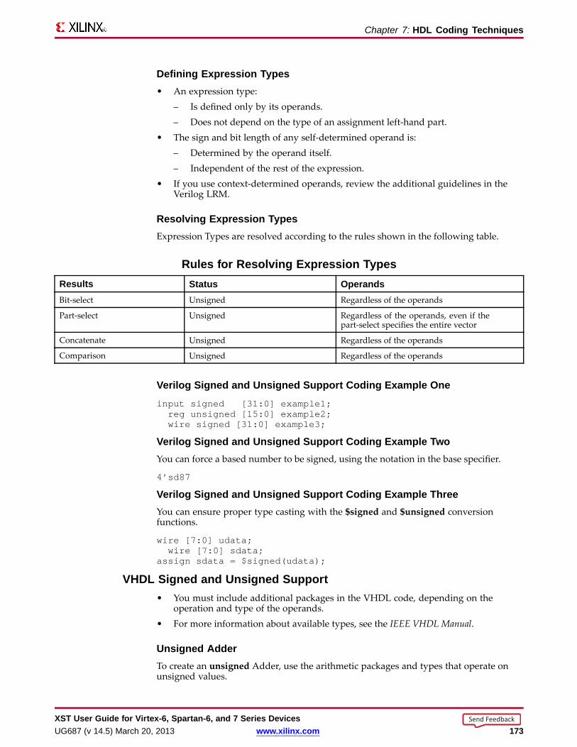
Chapter 7: HDL Coding Techniques
Defining Expression Types• An expression type:
– Is defined only by its operands.– Does not depend on the type of an assignment left-hand part.
• The sign and bit length of any self-determined operand is:– Determined by the operand itself.– Independent of the rest of the expression.
• If you use context-determined operands, review the additional guidelines in theVerilog LRM.
Resolving Expression TypesExpression Types are resolved according to the rules shown in the following table.
Rules for Resolving Expression TypesResults Status OperandsBit-select Unsigned Regardless of the operands
Part-select Unsigned Regardless of the operands, even if thepart-select specifies the entire vector
Concatenate Unsigned Regardless of the operands
Comparison Unsigned Regardless of the operands
Verilog Signed and Unsigned Suppor t Coding Example Oneinput signed [31:0] example1;reg unsigned [15:0] example2;wire signed [31:0] example3;
Verilog Signed and Unsigned Suppor t Coding Example TwoYou can force a based number to be signed, using the notation in the base specifier.
4’sd87
Verilog Signed and Unsigned Suppor t Coding Example ThreeYou can ensure proper type casting with the $signed and $unsigned conversionfunctions.
wire [7:0] udata;wire [7:0] sdata;
assign sdata = $signed(udata);
VHDL Signed and Unsigned Suppor t• You must include additional packages in the VHDL code, depending on the
operation and type of the operands.• For more information about available types, see the IEEE VHDL Manual.
Unsigned AdderTo create an unsigned Adder, use the arithmetic packages and types that operate onunsigned values.
XST User Guide for Vir tex-6, Spar tan-6, and 7 Series DevicesUG687 (v 14.5) March 20, 2013 www.xilinx.com 173
Send Feedback
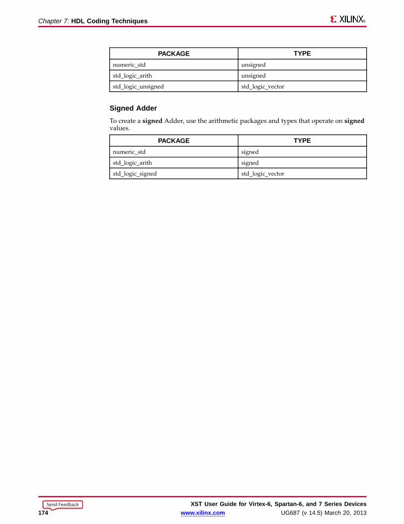
Chapter 7: HDL Coding Techniques
PACKAGE TYPEnumeric_std unsigned
std_logic_arith unsigned
std_logic_unsigned std_logic_vector
Signed AdderTo create a signed Adder, use the arithmetic packages and types that operate on signedvalues.
PACKAGE TYPEnumeric_std signed
std_logic_arith signed
std_logic_signed std_logic_vector
XST User Guide for Vir tex-6, Spar tan-6, and 7 Series Devices174 www.xilinx.com UG687 (v 14.5) March 20, 2013
Send Feedback
Chapter 7: HDL Coding Techniques
Arithmetic Operator s ImplementationArithmetic operators implementation includes:• Arithmetic Operators Slice Logic• Arithmetic Operators DSP Block Resources
Arithmetic Operator s Slice LogicXST leverages certain features of the Xilinx® CLB structure when implementingarithmetic macros on slice logic. These features include the dedicated carry logic forimplementing fast, efficient arithmetic functions.
Arithmetic Operator s DSP Bloc k Resour cesVirtex®-6, Spartan®-6, and 7 series devices contain dedicated high-performancearithmetic blocks (DSP blocks).• The number of DSP blocks depends on the device.• DSP blocks can be configured to implement various arithmetic functions.• If leveraged to their full potential, DSP blocks can implement a fully pipelined
preadder-multiply-add or preadder-multiply-accumulate function.• XST leverages those resources for high-performance and power-efficient
implementation of arithmetic logic.• Implementation of arithmetic macros on either slice logic or DSP block resources
is controlled by Use DSP Block with a value of auto.• In automode, XST takes into account the actual availability of DSP block resources
in order to avoid overmapping the device.– XST may use all available DSP resources available.– DSP Utilization Ratio forces XST to leave some DSP resources unallocated.
• Some arithmetic macros are not implemented on DSP blocks by default.– To force implementation of these macros, apply Use DSP Block with a value of
yes.– These macros include standalone:
♦ Adders♦ Accumulators♦ Counters
• To take advantage of Registers for pipelining arithmetic functions implemented onDSP blocks, describe the Registers with an optional clock enable.– Registers are optionally synchronously resettable.– Asynchronous reset logic prevents such implementation.– Xilinx® recommends that you not use asynchronous reset logic.
• DSP block resources assume signed operands. When describing unsignedarithmetic, you cannot map unsigned operands to the full width of a single DSPblock.Example– XST can implement up to a 25x18-bit signedmultiplication on a single Virtex-6
DSP48E1 block.– XST can implement up to a 24x17-bit unsigned product only on that same single
block, with most significant bits of the DSP block inputs set to 0.
XST User Guide for Vir tex-6, Spar tan-6, and 7 Series DevicesUG687 (v 14.5) March 20, 2013 www.xilinx.com 175
Send Feedback

Chapter 7: HDL Coding Techniques
More Information• For more information about implementation on DSP blocks, see:
– Multipliers
– Multiply-Add and Multiply-Accumulate
• For more information about DSP block resources, see:
– Virtex-6 FPGA DSP48E1 Slice User Guide (UG369) on the Xilinx support website.
– Spartan-6 FPGADSP48A1 Slice User Guide (UG389) on the Xilinx support website.
XST User Guide for Vir tex-6, Spar tan-6, and 7 Series Devices176 www.xilinx.com UG687 (v 14.5) March 20, 2013
Send Feedback
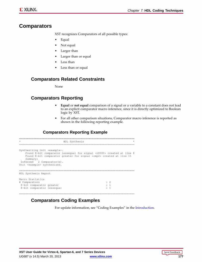
Chapter 7: HDL Coding Techniques
Comparator sXST recognizes Comparators of all possible types:
• Equal
• Not equal
• Larger than
• Larger than or equal
• Less than
• Less than or equal
Comparator s Related ConstraintsNone
Comparator s Repor ting• Equal or not equal comparison of a signal or a variable to a constant does not lead
to an explicit comparator macro inference, since it is directly optimized to Booleanlogic by XST.
• For all other comparison situations, Comparator macro inference is reported asshown in the following reporting example.
Comparator s Repor ting Example=========================================================================* HDL Synthesis *=========================================================================
Synthesizing Unit <example>.Found 8-bit comparator lessequal for signal <n0000> created at line 8Found 8-bit comparator greater for signal <cmp2> created at line 15Summary:
inferred 2 Comparator(s).Unit <example> synthesized.
=========================================================================HDL Synthesis Report
Macro Statistics# Comparators : 28-bit comparator greater : 18-bit comparator lessequal : 1
=========================================================================
Comparator s Coding ExamplesFor update information, see “Coding Examples” in the Introduction.
XST User Guide for Vir tex-6, Spar tan-6, and 7 Series DevicesUG687 (v 14.5) March 20, 2013 www.xilinx.com 177
Send Feedback
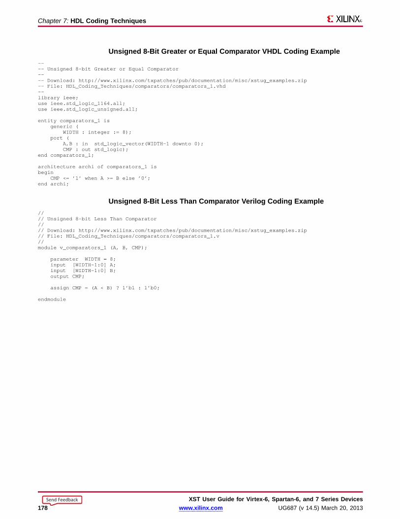
Chapter 7: HDL Coding Techniques
Unsigned 8-Bit Greater or Equal Comparator VHDL Coding Example---- Unsigned 8-bit Greater or Equal Comparator---- Download: http://www.xilinx.com/txpatches/pub/documentation/misc/xstug_examples.zip-- File: HDL_Coding_Techniques/comparators/comparators_1.vhd--library ieee;use ieee.std_logic_1164.all;use ieee.std_logic_unsigned.all;
entity comparators_1 isgeneric (
WIDTH : integer := 8);port (
A,B : in std_logic_vector(WIDTH-1 downto 0);CMP : out std_logic);
end comparators_1;
architecture archi of comparators_1 isbegin
CMP<= ’1’ when A >= B else ’0’;end archi;
Unsigned 8-Bit Less Than Comparator Verilog Coding Example//// Unsigned 8-bit Less Than Comparator//// Download: http://www.xilinx.com/txpatches/pub/documentation/misc/xstug_examples.zip// File: HDL_Coding_Techniques/comparators/comparators_1.v//module v_comparators_1 (A, B, CMP);
parameter WIDTH = 8;input [WIDTH-1:0] A;input [WIDTH-1:0] B;output CMP;
assign CMP= (A < B) ? 1’b1 : 1’b0;
endmodule
XST User Guide for Vir tex-6, Spar tan-6, and 7 Series Devices178 www.xilinx.com UG687 (v 14.5) March 20, 2013
Send Feedback

Chapter 7: HDL Coding Techniques
Divider sXST supports Dividers only if:
• The divisor is constant and a power of 2.
• The description is implemented as a shifter.
• Both operands are constant.
XST exits with a specific error message in all other cases.
Divider s Related ConstraintsNone
Divider s Repor tingNone
Divider s Coding ExamplesFor update information, see “Coding Examples” in the Introduction.
Division By Constant 2 VHDL Coding Example---- Division By Constant 2---- Download: http://www.xilinx.com/txpatches/pub/documentation/misc/xstug_examples.zip-- File: HDL_Coding_Techniques/dividers/dividers_1.vhd--library ieee;use ieee.std_logic_1164.all;use ieee.numeric_std.all;
entity divider_1 isport(DI : in unsigned(7 downto 0);
DO : out unsigned(7 downto 0));end divider_1;
architecture archi of divider_1 isbegin
DO <= DI / 2;
end archi;
Division By Constant 2 Verilog Coding Example//// Division By Constant 2//// Download: http://www.xilinx.com/txpatches/pub/documentation/misc/xstug_examples.zip// File: HDL_Coding_Techniques/dividers/dividers_1.v//module v_divider_1 (DI, DO);
input [7:0] DI;output [7:0] DO;
assign DO = DI / 2;
endmodule
XST User Guide for Vir tex-6, Spar tan-6, and 7 Series DevicesUG687 (v 14.5) March 20, 2013 www.xilinx.com 179
Send Feedback

Chapter 7: HDL Coding Techniques
Adders, Subtractor s, and Adders/Subtractor sXST recognizes:
• Adders
Adders can be described with:
– An optional carry input, and
– An optional carry output
• Subtractors
Subtractors can be described with an optional borrow input.
• Adder/Subtractors
Describing a Carry OutputA carry output is usually modeled by assigning 1) the result of the described addition,2) to a signal with an extra bit over the longest operand.
Describing a Carry Output VHDL Coding Example Oneinput [7:0] A;input [7:0] B;wire [8:0] res;wire carryout;
assign res = A + B;assign carryout = res[8];
Reviewing the Arithmetic PackageCarefully review the arithmetic package you plan to use for describing an Adder with acarry output. You may find that a particular method for describing an Adder does notwork with your chosen arithmetic package.
Reviewing the Arithmetic Package Example• The method in Coding Example One above does not work with the
std_logic_unsigned arithmetic package.
• The method does not work because the size of the result is necessarily equal to thesize of the longest argument.
• To make the method work, adjust the size of the operands as shown in the followingCoding Example Two.
Describing a Carry Output VHDL Coding Example Twosignal A : std_logic_unsigned(7 downto 0);signal B : std_logic_unsigned(7 downto 0);signal res : std_logic_unsigned(8 downto 0);signal carryout : std_logic;
res <= ("0" & A) + ("0" & B);carryout <= res[8];
XST User Guide for Vir tex-6, Spar tan-6, and 7 Series Devices180 www.xilinx.com UG687 (v 14.5) March 20, 2013
Send Feedback

Chapter 7: HDL Coding Techniques
Conver ting Operands to Type Integ er• In addition to adjusting the size of the operands, you can also:
1. Convert the operands to type integer.
2. Convert the result of the addition back to std_logic_vector.
• In the following Coding Example Three:
– The conv_std_logic_vector conversion function is contained in thestd_logic_arith arithmetic package.
– The unsigned + operation is contained in the std_logic_unsigned arithmeticpackage.
Describing a Carry Output VHDL Coding Example Threesignal A : std_logic_vector(7 downto 0);signal B : std_logic_vector(7 downto 0);signal res : std_logic_vector(8 downto 0);signal carryout : std_logic;
res <= conv_std_logic_vector((conv_integer(A) + conv_integer(B)),9);carryout <= res[8];
XST User Guide for Vir tex-6, Spar tan-6, and 7 Series DevicesUG687 (v 14.5) March 20, 2013 www.xilinx.com 181
Send Feedback
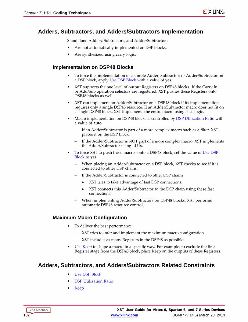
Chapter 7: HDL Coding Techniques
Adders, Subtractor s, and Adders/Subtractor s ImplementationStandalone Adders, Subtractors, and Adder/Subtractors:
• Are not automatically implemented on DSP blocks.
• Are synthesized using carry logic.
Implementation on DSP48 Bloc ks• To force the implementation of a simple Adder; Subtractor; or Adder/Subtractor on
a DSP block, apply Use DSP Block with a value of yes.
• XST supports the one level of output Registers on DSP48 blocks. If the Carry Inor Add/Sub operation selectors are registered, XST pushes these Registers ontoDSP48 blocks as well.
• XST can implement an Adder/Subtractor on a DSP48 block if its implementationrequires only a single DSP48 resource. If an Adder/Subtractor macro does not fit ona single DSP48 block, XST implements the entire macro using slice logic.
• Macro implementation on DSP48 blocks is controlled by DSP Utilization Ratio witha value of auto.
– If an Adder/Subtractor is part of a more complex macro such as a filter, XSTplaces it on the DSP block.
– If the Adder/Subtractor is NOT part of a more complex macro, XST implementsthe Adder/Subtractor using LUTs.
• To force XST to push these macros onto a DSP48 block, set the value of Use DSPBlock to yes.
– When placing an Adder/Subtractor on a DSP block, XST checks to see if it isconnected to other DSP chains.
– If the Adder/Subtractor is connected to other DSP chains:
♦ XST tries to take advantage of fast DSP connections.
♦ XST connects this Adder/Subtractor to the DSP chain using these fastconnections.
– When implementing Adder/Subtractors on DSP48 blocks, XST performsautomatic DSP48 resource control.
Maximum Macro Configuration• To deliver the best performance:
– XST tries to infer and implement the maximum macro configuration.
– XST includes as many Registers in the DSP48 as possible.
• Use Keep to shape a macro in a specific way. For example, to exclude the firstRegister stage from the DSP48 block, place Keep on the outputs of these Registers.
Adders, Subtractor s, and Adders/Subtractor s Related Constraints• Use DSP Block
• DSP Utilization Ratio
• Keep
XST User Guide for Vir tex-6, Spar tan-6, and 7 Series Devices182 www.xilinx.com UG687 (v 14.5) March 20, 2013
Send Feedback
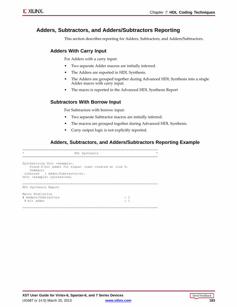
Chapter 7: HDL Coding Techniques
Adders, Subtractor s, and Adders/Subtractor s Repor tingThis section describes reporting for Adders, Subtractors, and Adders/Subtractors.
Adders With Carry InputFor Adders with a carry input:
• Two separate Adder macros are initially inferred.
• The Adders are reported in HDL Synthesis.
• The Adders are grouped together during Advanced HDL Synthesis into a singleAdder macro with carry input.
• The macro is reported in the Advanced HDL Synthesis Report
Subtractor s With Borr ow InputFor Subtractors with borrow input:
• Two separate Subtractor macros are initially inferred.
• The macros are grouped together during Advanced HDL Synthesis.
• Carry output logic is not explicitly reported.
Adders, Subtractor s, and Adders/Subtractor s Repor ting Example=========================================================================* HDL Synthesis *=========================================================================
Synthesizing Unit <example>.Found 8-bit adder for signal <sum> created at line 9.Summary:
inferred 1 Adder/Subtractor(s).Unit <example> synthesized.
=========================================================================HDL Synthesis Report
Macro Statistics# Adders/Subtractors : 18-bit adder : 1
=========================================================================
XST User Guide for Vir tex-6, Spar tan-6, and 7 Series DevicesUG687 (v 14.5) March 20, 2013 www.xilinx.com 183
Send Feedback
Chapter 7: HDL Coding Techniques
Adders, Subtractor s, and Adders/Subtractor s Coding ExamplesFor update information, see “Coding Examples” in the Introduction.
Unsigned 8-Bit Adder VHDL Coding Example---- Unsigned 8-bit Adder---- Download: http://www.xilinx.com/txpatches/pub/documentation/misc/xstug_examples.zip-- File: HDL_Coding_Techniques/adders/adders_1.vhd--library ieee;use ieee.std_logic_1164.all;use ieee.std_logic_unsigned.all;
entity adders_1 isgeneric (
WIDTH : integer := 8);port (
A, B : in std_logic_vector(WIDTH-1 downto 0);SUM : out std_logic_vector(WIDTH-1 downto 0));
end adders_1;
architecture archi of adders_1 isbegin
SUM<= A + B;end archi;
Unsigned 8-Bit Adder with Carry In Verilog Coding Example//// Unsigned 8-bit Adder with Carry In//// Download: http://www.xilinx.com/txpatches/pub/documentation/misc/xstug_examples.zip// File: HDL_Coding_Techniques/adders/adders_2.v//module v_adders_2 (A, B, CI, SUM);
parameter WIDTH = 8;input [WIDTH-1:0] A;input [WIDTH-1:0] B;input CI;output [WIDTH-1:0] SUM;
assign SUM= A + B + CI;
endmodule
XST User Guide for Vir tex-6, Spar tan-6, and 7 Series Devices184 www.xilinx.com UG687 (v 14.5) March 20, 2013
Send Feedback
Chapter 7: HDL Coding Techniques
Multiplier sXST infers Multiplier macros from product operators in the source code.
• The resulting signal equals the sum of the two operand sizes. For example,multiplying a 16-bit signal by an 8-bit signal produces a result of 24 bits.
• If you do not intend to use all most significant bits of a device, Xilinx® recommendsthat you reduce the size of operands to the minimum needed, especially if theMultiplier macro will be implemented on slice logic.
Multiplier s Implementation• Multiplier macros can be implemented on:
– Slice logic
– DSP blocks
• Implementing a Multiplier on either slice logic or DSP block resources is controlledby Use DSP Block with a value of auto.
• In auto mode:
– XST tries to implement a Multiplier on DSP block resources. Its operands musthave a minimum size. The minimum size can vary depending on the devicefamily.
– XST considers the actual availability of DSP block resources in order to avoidovermapping the device. XST may use all available DSP resources. DSPUtilization Ratio forces XST to leave some of those resources unallocated.
• To force implementation of a Multiplier to slice logic or DSP block, set Use DSPBlock on the appropriate signal, entity, or module to either:
– no (slice logic)
– yes (DSP block)
XST User Guide for Vir tex-6, Spar tan-6, and 7 Series DevicesUG687 (v 14.5) March 20, 2013 www.xilinx.com 185
Send Feedback

Chapter 7: HDL Coding Techniques
DSP Bloc k Implementation• When implementing a Multiplier in a single DSP block, XST tries to take advantage
of the pipelining capabilities of DSP blocks. XST pulls up to two levels of Registerspresent:
– On the multiplication operands
– Behind the multiplication
• When a Multiplier does not fit on a single DSP block, XST decomposes the macroto implement it. In that case, XST uses:
– Several DSP blocks, or
– A hybrid solution involving both DSP blocks and slice logic
• The implementation choice is:
– Driven by the size of operands
– Aimed at maximizing performance
• Pipelining can improve the performance of implementations based on multiple DSPblocks. Apply Multiplier Style with a value of pipe_block.
• During pipelining, XST calculates the ideal number of Register levels needed tomaximize the performance of a given Multiplier.
– If the ideal number of Register levels is available, XST moves the Register levelsin order to achieve the desired goal.
– If the ideal number of Register levels is NOT available, XST issues the followingmessage.
INFO:Xst:2385 - HDL ADVISOR - You can improve the performance of themultiplier Mmult_n0005 by adding 2 register level(s).
• You can insert the suggested amount of additional Register levels behind themultiplication.
• Use Keep to restrict absorption of Registers into DSP blocks. For example, if aRegister is present on an operand of the multiplier, place Keep on the output of theRegister to prevent the Register from being absorbed into the DSP block.
lice Logic ImplementationWhen Use DSP Block is set to auto, most Multipliers are implemented on DSP blockresources, provided that:
• One or more latency stages is available, and
• The latency stage is within the limits of available DSP blocks.
Forcing Multiplier Implementation on Slice Logic• To force a Multiplier to be implemented on slice logic, apply Use DSP Block with
a value of no.
• For a Multiplier implemented on slice logic:
– XST looks for pipelining opportunities around the operator.
– XST moves those registers in order to reduce data path length.
XST User Guide for Vir tex-6, Spar tan-6, and 7 Series Devices186 www.xilinx.com UG687 (v 14.5) March 20, 2013
Send Feedback

Chapter 7: HDL Coding Techniques
Increasing Performance of Large Multiplier s by PipeliningPipelining can greatly increase the performance of large Multipliers.
• The effect of pipelining is similar to Flip-Flop retiming.
• To insert pipeline stages:
1. Describe the Registers.
2. Place them after the Multiplier.
3. Set Multiplier Style to pipe_lut.
Multiplication to a Constant• XST can use either of two dedicated implementation methods when one argument
of the multiplication is a constant.
– Constant Coefficient Multiplier (CCM)
– Canonical Signed Digit (CSD)
• These methods apply only when the multiplication is implemented on slice logic.
• The level of optimization depends on the characteristics of the constant operand.
– CCM implementation is not always better than the default slice logicimplementation.
– XST chooses between CCM or standard multiplier implementation.
• The CSD method cannot be chosen automatically. Use Multiplier Style to:
– Force CSD implementation
– Force CCM implementation
• XST does not use CCM or CSD implementations if:
– The multiplication is signed.
– One of the operands is larger than 32 bits.
Multiplier s Related Constraints• Use DSP Block
• DSP Utilization Ratio
• Keep
• Multiplier Style
Multiplier s Repor ting• Multipliers are inferred during HDL Synthesis.
• Registers can be absorbed by a Multiplier macro during Advanced HDL Synthesis.See the following reporting example.
XST User Guide for Vir tex-6, Spar tan-6, and 7 Series DevicesUG687 (v 14.5) March 20, 2013 www.xilinx.com 187
Send Feedback

Chapter 7: HDL Coding Techniques
Multiplier s Repor ting Example=========================================================================* HDL Synthesis *=========================================================================
Synthesizing Unit <v_multipliers_11>.Found 8-bit register for signal <rB>.Found 24-bit register for signal <RES>.Found 16-bit register for signal <rA>.Found 16x8-bit multiplier for signal <n0005> created at line 20.Summary:
inferred 1 Multiplier(s).inferred 48 D-type flip-flop(s).Unit <v_multipliers_11> synthesized.
=========================================================================HDL Synthesis Report
Macro Statistics# Multipliers : 116x8-bit multiplier : 1# Registers : 316-bit register : 124-bit register : 18-bit register : 1
=========================================================================
=========================================================================* Advanced HDL Synthesis *=========================================================================
Synthesizing (advanced) Unit <v_multipliers_11>.Found pipelined multiplier on signal <n0005>:- 1 pipeline level(s) found in a register connected to the multiplier
macro output.Pushing register(s) into the multiplier macro.
- 1 pipeline level(s) found in a register on signal <rA>.Pushing register(s) into the multiplier macro.
- 1 pipeline level(s) found in a register on signal <rB>.Pushing register(s) into the multiplier macro.
INFO:Xst:2385 - HDL ADVISOR - You can improve the performance of themultiplier Mmult_n0005 by adding 1 register level(s).Unit <v_multipliers_11> synthesized (advanced).
=========================================================================Advanced HDL Synthesis Report
Macro Statistics# Multipliers : 116x8-bit registered multiplier : 1
=========================================================================
Multiplier s Coding ExamplesFor update information, see “Coding Examples” in the Introduction.
XST User Guide for Vir tex-6, Spar tan-6, and 7 Series Devices188 www.xilinx.com UG687 (v 14.5) March 20, 2013
Send Feedback
Chapter 7: HDL Coding Techniques
Unsigned 8x4-Bit Multiplier VHDL Coding Example---- Unsigned 8x4-bit Multiplier---- Download: http://www.xilinx.com/txpatches/pub/documentation/misc/xstug_examples.zip-- File: HDL_Coding_Techniques/multipliers/multipliers_1.vhd--library ieee;use ieee.std_logic_1164.all;use ieee.std_logic_unsigned.all;
entity multipliers_1 isgeneric (
WIDTHA : integer := 8;WIDTHB : integer := 4);
port(A : in std_logic_vector(WIDTHA-1 downto 0);B : in std_logic_vector(WIDTHB-1 downto 0);RES : out std_logic_vector(WIDTHA+WIDTHB-1 downto 0));
end multipliers_1;
architecture beh of multipliers_1 isbegin
RES <= A * B;end beh;
Unsigned 32x24-Bit Multiplier Verilog Coding Example//// Unsigned 32x24-bit Multiplier// 1 latency stage on operands// 3 latency stage after the multiplication//// Download: http://www.xilinx.com/txpatches/pub/documentation/misc/xstug_examples.zip// File: HDL_Coding_Techniques/multipliers/multipliers_11.v//module v_multipliers_11 (clk, A, B, RES);
parameter WIDTHA = 32;parameter WIDTHB = 24;input clk;input [WIDTHA-1:0] A;input [WIDTHB-1:0] B;output [WIDTHA+WIDTHB-1:0] RES;
reg [WIDTHA-1:0] rA;reg [WIDTHB-1:0] rB;reg [WIDTHA+WIDTHB-1:0] M [3:0];integer i;
always @(posedge clk)begin
rA <= A;rB <= B;
M[0] <= rA * rB;for (i = 0; i < 3; i = i+1)M[i+1] <= M[i];endassign RES = M[3];
endmodule
XST User Guide for Vir tex-6, Spar tan-6, and 7 Series DevicesUG687 (v 14.5) March 20, 2013 www.xilinx.com 189
Send Feedback
Chapter 7: HDL Coding Techniques
Multipl y-Add and Multipl y-Accum ulate• The following macros are inferred during Advanced HDL Synthesis:
– Multiply-Add– Multiply-Sub– Multiply-Add/Sub– Multiply-Accumulate
• The macros are inferred by aggregation of:– A Multiplier– An Adder/Subtractor– Registers previously inferred during HDL Synthesis
Multipl y-Add and Multipl y-Accum ulate Implementation• During Multiply-Add and Multiply-Accumulate implementation:
– XST can implement an inferred Multiply-Add or Multiply-Accumulate macroon DSP block resources.
– XST tries to take advantage pipelining capabilities of DSP blocks.– XST pulls up to:
♦ Two register stages present on the multiplication operands.♦ One register stage present behind the multiplication.♦ One register stage found behind the Adder, Subtractor, or Adder/Subtractor.♦ One register stage on the add/sub selection signal.♦ One register stage on the Adder optional carry input.
– XST can implement a Multiply Accumulate in a DSP48 block if itsimplementation requires only a single DSP48 resource.
• If the macro exceeds the limits of a single DSP48:– XST processes it as two separate Multiplier and Accumulate macros.– XST makes independent decisions on each macro.
Macro Implementation on DSP Bloc k Resour cesMacro implementation on DSP block resources is controlled by Use DSP Block with avalue of auto.• In auto mode, XST:
– Implements Multiply-Add and Multiply-Accumulate Macros.– Takes into account DSP block resources availability in the targeted device.– May use all available DSP resources.
DSP Utilization Ratio forces XST to leave some of those resources unallocated.– Tries to maximize circuit performance by leveraging all pipelining capabilities
of DSP blocks.– Looks for all opportunities to absorb Registers into a Multiply-Add or
Multiply-Accumulate macro.• Use Keep to restrict absorption of Registers into DSP blocks. For example, to exclude
a Register present on an operand of the Multiplier from absorption into the DSPblock, apply Keep on the output of the Register.
XST User Guide for Vir tex-6, Spar tan-6, and 7 Series Devices190 www.xilinx.com UG687 (v 14.5) March 20, 2013
Send Feedback

Chapter 7: HDL Coding Techniques
Multipl y-Add and Multipl y-Accum ulate Related Constraints• Use DSP Block
• DSP Utilization Ratio
• Keep
Multipl y-Add and Multipl y-Accum ulate Repor tingXST reports the details of inferred Multipliers, Accumulators, and Registers duringHDL Synthesis.
• The Advanced HDL Synthesis section displays information about the compositionof those macros into a Multiply-Add or Multiply-Accumulate macro.
• Both types of functionalities are accounted for under the unifiedMAC denomination.
Multipl y-Add and Multipl y-Accum ulate Repor ting Example=========================================================================* HDL Synthesis *=========================================================================
Synthesizing Unit <v_multipliers_7a>.Found 16-bit register for signal <accum>.Found 16-bit register for signal <mult>.Found 16-bit adder for signal <n0058> created at line 26.Found 8x8-bit multiplier for signal <n0005> created at line 18.Summary:
inferred 1 Multiplier(s).inferred 1 Adder/Subtractor(s).inferred 32 D-type flip-flop(s).Unit <v_multipliers_7a> synthesized.
=========================================================================HDL Synthesis Report
Macro Statistics# Multipliers : 18x8-bit multiplier : 1# Adders/Subtractors : 116-bit adder : 1# Registers : 216-bit register : 2
=========================================================================
=========================================================================* Advanced HDL Synthesis *=========================================================================
Synthesizing (advanced) Unit <v_multipliers_7a>.The following registers are absorbed into accumulator <accum>: 1 registeron signal <accum>.Multiplier <Mmult_n0005> in block <v_multipliers_7a> and accumulator<accum> in block <v_multipliers_7a> are combined into a MAC<Mmac_n0005>.The following registers are also absorbed by the MAC: <mult> in block<v_multipliers_7a>.Unit <v_multipliers_7a> synthesized (advanced).
=========================================================================Advanced HDL Synthesis Report
Macro Statistics# MACs : 18x8-to-16-bit MAC : 1
=========================================================================
XST User Guide for Vir tex-6, Spar tan-6, and 7 Series DevicesUG687 (v 14.5) March 20, 2013 www.xilinx.com 191
Send Feedback
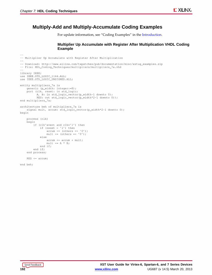
Chapter 7: HDL Coding Techniques
Multipl y-Add and Multipl y-Accum ulate Coding ExamplesFor update information, see “Coding Examples” in the Introduction.
Multiplier Up Accum ulate with Register After Multiplication VHDL CodingExample
---- Multiplier Up Accumulate with Register After Multiplication---- Download: http://www.xilinx.com/txpatches/pub/documentation/misc/xstug_examples.zip-- File: HDL_Coding_Techniques/multipliers/multipliers_7a.vhd--library IEEE;use IEEE.STD_LOGIC_1164.ALL;use IEEE.STD_LOGIC_UNSIGNED.ALL;
entity multipliers_7a isgeneric (p_width: integer:=8);port (clk, reset: in std_logic;
A, B: in std_logic_vector(p_width-1 downto 0);RES: out std_logic_vector(p_width*2-1 downto 0));
end multipliers_7a;
architecture beh of multipliers_7a issignal mult, accum: std_logic_vector(p_width*2-1 downto 0);
begin
process (clk)begin
if (clk’event and clk=’1’) thenif (reset = ’1’) then
accum <= (others => ’0’);mult <= (others => ’0’);
elseaccum <= accum + mult;mult <= A * B;
end if;end if;
end process;
RES <= accum;
end beh;
XST User Guide for Vir tex-6, Spar tan-6, and 7 Series Devices192 www.xilinx.com UG687 (v 14.5) March 20, 2013
Send Feedback

Chapter 7: HDL Coding Techniques
Multiplier Up Accum ulate Verilog Coding Example//// Multiplier Up Accumulate with:// Registered operands// Registered multiplication// Accumulation//// Download: http://www.xilinx.com/txpatches/pub/documentation/misc/xstug_examples.zip// File: HDL_Coding_Techniques/multipliers/multiply_accum_2.v//module v_multiply_accum_2 (clk, rst, A, B, RES);
parameter WIDTH = 8;input clk;input rst;input [WIDTH-1:0] A, B;output [2*WIDTH-1:0] RES;
reg [WIDTH-1:0] rA, rB;reg [2*WIDTH-1:0] mult, accum;
always @(posedge clk)begin
if (rst) beginrA <= {WIDTH{1’b0}};rB <= {WIDTH{1’b0}};
mult <= {2*WIDTH{1’b0}};accum <= {2*WIDTH{1’b0}};
endelse begin
rA <= A;rB <= B;
mult <= rA * rB;accum <= accum + mult;
endendassign RES = accum;
endmodule
XST User Guide for Vir tex-6, Spar tan-6, and 7 Series DevicesUG687 (v 14.5) March 20, 2013 www.xilinx.com 193
Send Feedback
Chapter 7: HDL Coding Techniques
Extended DSP InferencingXST provides extended inferencing capabilities for describing filters with portablebehavioral source code.• XST offers finer-grained inferencing capabilities for such basic functionalities as:
– Latency stages (registers)– Multiply– Multiply-add/subtract– Accumulate– Multiply-accumulate– ROM
• In order to achieve high performance implementation and power reduction, XSTattempts to:– Understand the existence of any contextual relationship between basic
functional elements.– Leverage the features of the DSP block resources available on Xilinx® devices:
♦ Pipelining stages♦ Cascade paths♦ Pre-adder stage♦ Time multiplexing
• To optimally leverage DSP block capabilities, use an adder chain instead of an addertree as the backbone of the filter description. Some HDL language features, such asfor generate (VHDL), facilitate describing a filter in this way, and ensure maximalreadability and scalability of the code.
• For more information about DSP block resources, see:– Virtex-6 FPGA DSP48E1 Slice User Guide (UG369) on the Xilinx support website.– Spartan-6 FPGADSP48A1 Slice User Guide (UG389) on the Xilinx support website.
Symmetric Filter sThe optional pre-Adder capability in DSP Blocks was designed for symmetric filters.If you describe a symmetric coefficients filter, leverage the pre-Adder to reduce thenumber of required DSP blocks by half.• Do not describe the filter generically and assume that XST will be able to determine
the symmetry.– XST does not automatically identify and factor symmetric coefficients.– You must manually code the factorized form in order for XST to see the
pre-Adder opportunity and configure DSP blocks accordingly.– See the SymSystolicFilter and SymTransposeConvFilter coding examples below.
• To leverage the pre-Adder capability, XST must identify a description that exactlymatches the pre-Adder size characteristics, even though your data may be of alower width.– This requirement is specific to the pre-Adder.– Use signed or unsigned extensions for explicit padding of the pre-Adder
operands to ensure proper inference and implementation on DSP resources. Seethe following coding example.
XST User Guide for Vir tex-6, Spar tan-6, and 7 Series Devices194 www.xilinx.com UG687 (v 14.5) March 20, 2013
Send Feedback

Chapter 7: HDL Coding Techniques
Pre-Adder Description With Explicit Data Extensions Coding Example---- Explicit padding of pre-adder operands---- Download: http://www.xilinx.com/txpatches/pub/documentation/misc/xstug_examples.zip-- File: HDL_Coding_Techniques/dsp/preadder_padding.vhd--library ieee;use ieee.std_logic_1164.all;use ieee.numeric_std.all;
entity preadder_padding is
generic (DATA_WIDTH : integer := 16
);port (clk : in std_logic;a : in signed(DATA_WIDTH-1 downto 0);b : in signed(DATA_WIDTH-1 downto 0);c : in signed(DATA_WIDTH-1 downto 0);d : in signed(2*DATA_WIDTH-1 downto 0);o : out signed(2*DATA_WIDTH-1 downto 0)
);
end preadder_padding;
architecture behavioral of preadder_padding is
constant PREADD_WIDTH: integer := 18;signal a_resized : signed(PREADD_WIDTH-1 downto 0);signal b_resized : signed(PREADD_WIDTH-1 downto 0);signal pre : signed(PREADD_WIDTH-1 downto 0);signal m : signed(DATA_WIDTH+PREADD_WIDTH-1 downto 0);signal p : signed(DATA_WIDTH+PREADD_WIDTH-1 downto 0);
begin
assert DATA_WIDTH<= PREADD_WIDTHreport "DATA_WIDTH exceeds limit of 18 bits" severity ERROR;
a_resized <= RESIZE(a, PREADD_WIDTH);b_resized <= RESIZE(b, PREADD_WIDTH);
process (clk)beginif rising_edge(clk) thenpre <= a_resized + b_resized;m <= pre * c;p <= m + d;
end if;end process;
o <= RESIZE(p, 2*DATA_WIDTH);
end behavioral;
XST User Guide for Vir tex-6, Spar tan-6, and 7 Series DevicesUG687 (v 14.5) March 20, 2013 www.xilinx.com 195
Send Feedback
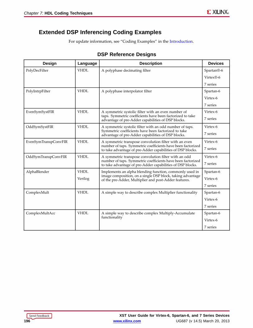
Chapter 7: HDL Coding Techniques
Extended DSP Inferencing Coding ExamplesFor update information, see “Coding Examples” in the Introduction.
DSP Reference DesignsDesign Langua ge Description Devices
PolyDecFilter VHDL A polyphase decimating filter Spartan®-6
Virtex®-6
7 series
PolyIntrpFilter VHDL A polyphase interpolator filter Spartan-6
Virtex-6
7 series
EvenSymSystFIR VHDL A symmetric systolic filter with an even number oftaps. Symmetric coefficients have been factorized to takeadvantage of pre-Adder capabilities of DSP blocks.
Virtex-6
7 series
OddSymSystFIR VHDL A symmetric systolic filter with an odd number of taps.Symmetric coefficients have been factorized to takeadvantage of pre-Adder capabilities of DSP blocks.
Virtex-6
7 series
EvenSymTranspConvFIR VHDL A symmetric transpose convolution filter with an evennumber of taps. Symmetric coefficients have been factorizedto take advantage of pre-Adder capabilities of DSP blocks.
Virtex-6
7 series
OddSymTranspConvFIR VHDL A symmetric transpose convolution filter with an oddnumber of taps. Symmetric coefficients have been factorizedto take advantage of pre-Adder capabilities of DSP blocks.
Virtex-6
7 series
AlphaBlender VHDL
Verilog
Implements an alpha blending function, commonly used inimage composition, on a single DSP block, taking advantageof the pre-Adder, Multiplier and post-Adder features.
Spartan-6
Virtex-6
7 series
ComplexMult VHDL A simple way to describe complex Multiplier functionality Spartan-6
Virtex-6
7 series
ComplexMultAcc VHDL A simple way to describe complex Multiply-Accumulatefunctionality
Spartan-6
Virtex-6
7 series
XST User Guide for Vir tex-6, Spar tan-6, and 7 Series Devices196 www.xilinx.com UG687 (v 14.5) March 20, 2013
Send Feedback

Chapter 7: HDL Coding Techniques
Resour ce SharingXST implements high-level optimizations known as Resource Sharing.
• Resource Sharing minimizes the number of arithmetic operators, resulting inreduced device utilization.
• Resource Sharing is based on the principle that two similar arithmetic operators canbe implemented with common resources on the device, provided their respectiveoutputs are never used simultaneously.
• Resource Sharing usually involves creating additional multiplexing logic to selectbetween factorized inputs. Factorization is performed in a way that minimizesthis logic.
• Resource Sharing is enabled by default, no matter which overall optimizationstrategy you have selected.
XST Resour ce Sharing Suppor tXST supports Resource Sharing for:
• Adders
• Subtractors
• Adders/Subtractors
• Multipliers
Disab ling Resour ce Sharing• Xilinx® recommends that you disable Resource Sharing:
– If circuit performance is your primary optimization goal, and
– You are unable to meet timing goals.
• An HDL Advisor message informs you when Resource Sharing has taken place.
Resour ce Sharing Related ConstraintsResource Sharing
Resour ce Sharing Repor tingArithmetic Resource Sharing:
• Takes place during HDL Synthesis.
• Is reflected by:
– Arithmetic macro statistics
– An HDL Advisor message
XST User Guide for Vir tex-6, Spar tan-6, and 7 Series DevicesUG687 (v 14.5) March 20, 2013 www.xilinx.com 197
Send Feedback
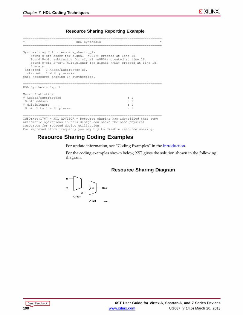
Chapter 7: HDL Coding Techniques
Resour ce Sharing Repor ting Example=========================================================================* HDL Synthesis *=========================================================================
Synthesizing Unit <resource_sharing_1>.Found 8-bit adder for signal <n0017> created at line 18.Found 8-bit subtractor for signal <n0004> created at line 18.Found 8-bit 2-to-1 multiplexer for signal <RES> created at line 18.Summary:
inferred 1 Adder/Subtractor(s).inferred 1 Multiplexer(s).Unit <resource_sharing_1> synthesized.
=========================================================================HDL Synthesis Report
Macro Statistics# Adders/Subtractors : 18-bit addsub : 1# Multiplexers : 18-bit 2-to-1 multiplexer : 1
=========================================================================INFO:Xst:1767 - HDL ADVISOR - Resource sharing has identified that somearithmetic operations in this design can share the same physicalresources for reduced device utilization.For improved clock frequency you may try to disable resource sharing.
Resour ce Sharing Coding ExamplesFor update information, see “Coding Examples” in the Introduction.
For the coding examples shown below, XST gives the solution shown in the followingdiagram.
Resour ce Sharing Diagram
XST User Guide for Vir tex-6, Spar tan-6, and 7 Series Devices198 www.xilinx.com UG687 (v 14.5) March 20, 2013
Send Feedback
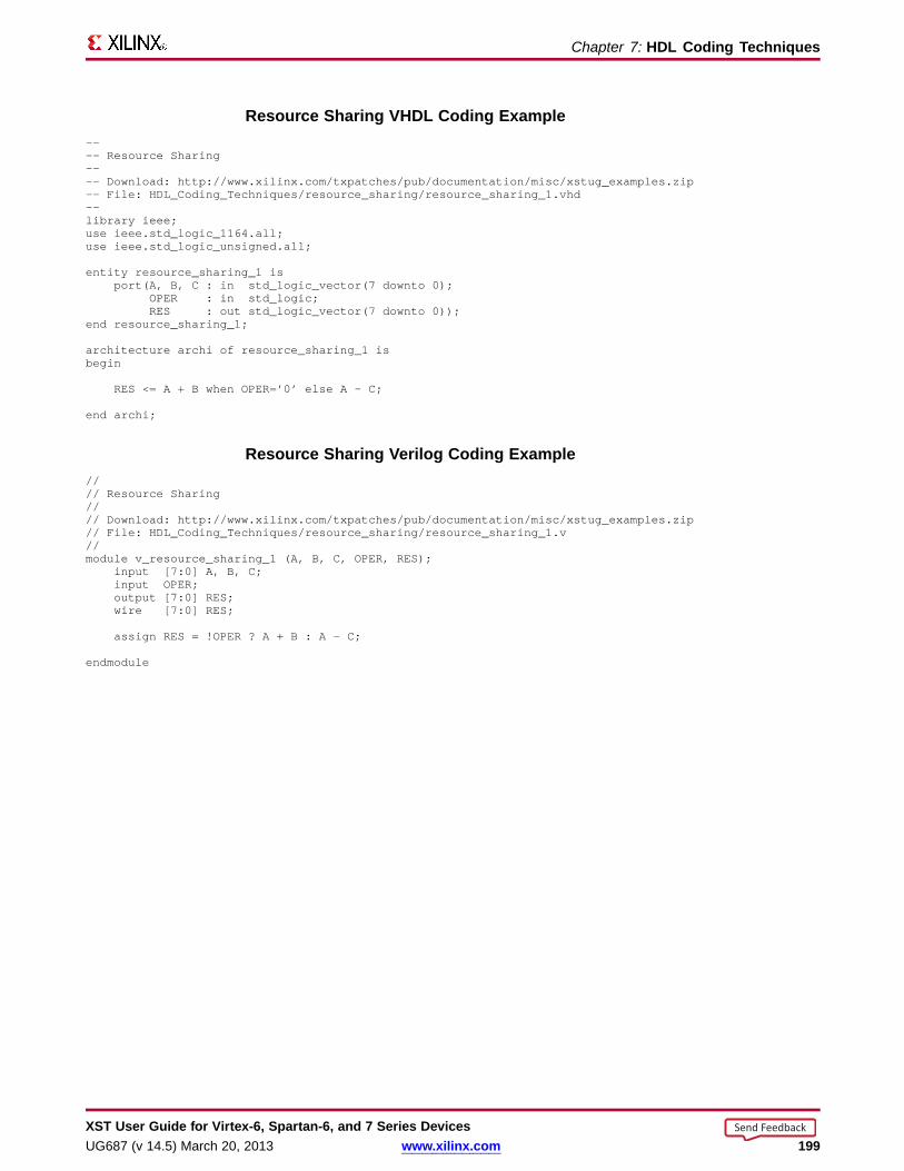
Chapter 7: HDL Coding Techniques
Resour ce Sharing VHDL Coding Example---- Resource Sharing---- Download: http://www.xilinx.com/txpatches/pub/documentation/misc/xstug_examples.zip-- File: HDL_Coding_Techniques/resource_sharing/resource_sharing_1.vhd--library ieee;use ieee.std_logic_1164.all;use ieee.std_logic_unsigned.all;
entity resource_sharing_1 isport(A, B, C : in std_logic_vector(7 downto 0);
OPER : in std_logic;RES : out std_logic_vector(7 downto 0));
end resource_sharing_1;
architecture archi of resource_sharing_1 isbegin
RES <= A + B when OPER=’0’ else A - C;
end archi;
Resour ce Sharing Verilog Coding Example//// Resource Sharing//// Download: http://www.xilinx.com/txpatches/pub/documentation/misc/xstug_examples.zip// File: HDL_Coding_Techniques/resource_sharing/resource_sharing_1.v//module v_resource_sharing_1 (A, B, C, OPER, RES);
input [7:0] A, B, C;input OPER;output [7:0] RES;wire [7:0] RES;
assign RES = !OPER ? A + B : A - C;
endmodule
XST User Guide for Vir tex-6, Spar tan-6, and 7 Series DevicesUG687 (v 14.5) March 20, 2013 www.xilinx.com 199
Send Feedback

Chapter 7: HDL Coding Techniques
RAM HDL Coding TechniquesXST extended Random Access Memory (RAM) inferencing:
• Makes it unnecessary to manually instantiate RAM primitives.
• Saves time.
• Keeps HDL source code portable and scalable.
Distrib uted RAM and Dedicated Bloc k RAM• RAM resources are of two types:
– Distributed RAM
Must be used for RAM descriptions with asynchronous read.
– Dedicated block RAM
Generally used for RAM descriptions with synchronous read.
• Use RAM Style to control RAM implementation.
• For more information, see distributed RAM and related topics in:
– Virtex-6 FPGA Memory Resources User Guide
– Virtex-6 FPGA Configurable Logic Block User Guide
– Spartan-6 FPGA Block RAM Resources User Guide
– Spartan-6 FPGA Configurable Logic Block User Guide
Distrib uted RAM and Dedicated Bloc k RAM ComparisonData is written synchronously into the RAM for both types. The primary differencebetween distributed RAM and dedicated block RAM lies in the way data is read from theRAM. See the following table.
Action Distrib uted RAM Dedicated Bloc k RamWrite Synchronous Synchronous
Read Asynchronous Synchronous
Choosing Between Distrib uted RAM and Dedicated Bloc k RAMWhether to use distributed RAM or dedicated block RAM may depend on:
• The characteristics of the RAM you have described in the HDL source code
• Whether you have forced a specific implementation style
• Availability of block RAM resources
Async hronous Read (Distrib uted RAM)• RAM descriptions with asynchronous read:
– Are implemented with distributed RAM.
– Cannot be implemented in dedicated block RAM.
• Distributed RAM is implemented on properly configured slice logic.
XST User Guide for Vir tex-6, Spar tan-6, and 7 Series Devices200 www.xilinx.com UG687 (v 14.5) March 20, 2013
Send Feedback

Chapter 7: HDL Coding Techniques
Synchronous Read (Dedicated Bloc k RAM)RAM descriptions with synchronous read:
• Generally go into dedicated block RAM.
• Are implemented using distributed RAM plus additional registers if you have sorequested, or for device resource utilization.
RAM-Suppor ted FeaturesRAM-supported features include:
• RAM Inferencing Capabilities
• Parity Bits
RAM Inferencing CapabilitiesRAM inferencing capabilities include the following.
• Support for any size and data width. XST maps the RAM description to one orseveral RAM primitives.
• Single-port, simple-dual port, true dual port.
• Up to two write ports.
• Multiple read ports.
Provided that only one write port is described, XST can identify RAM descriptionswith two or more read ports that access the RAM contents at addresses differentfrom the write address.
• Simple-dual port and true dual-port RAM with asymmetric ports. For moreinformation, see Asymmetric Ports Support (Block RAM).
• Write enable.
• RAM enable (block RAM).
• Data output reset (block RAM).
• Optional output register (block RAM).
• Byte-Wide Write Enable (block RAM).
• Each RAM port can be controlled by its distinct clock, RAM enable, write enable,and data output reset.
• Initial contents specification.
Parity BitsXST does not support parity bits.
• Parity bits are available on certain block RAM primitives.
• XST can use parity bits as regular data bits in order to accommodate the describeddata widths.
• XST cannot:
– Automatically generate parity control logic.
– Use those parity bit positions for their intended purpose.
XST User Guide for Vir tex-6, Spar tan-6, and 7 Series DevicesUG687 (v 14.5) March 20, 2013 www.xilinx.com 201
Send Feedback

Chapter 7: HDL Coding Techniques
RAM HDL Coding GuidelinesRAM HDL coding guidelines include:
• RAM Modeling
• Describing Read Access
• Block RAM Read/Write Synchronization
• Re-Settable Data Outputs (Block RAM)
• Byte-Write Enable Support (Block RAM)
• Asymmetric Ports Support
• RAM Initial Contents
RAM ModelingRAM is usually modeled with an array of array object.
Modeling a RAM in VHDL (Single Write Por t)To model a RAM with a single write port, use a VHDL signal as follows:
type ram_type is array (0 to 255) of std_logic_vector (15 downto 0);signal RAM : ram_type;
Modeling a RAM in VHDL (Two Write Por ts)To model a RAM with two write ports in VHDL, use a shared variable instead of a signal.
type ram_type is array (0 to 255) of std_logic_vector (15 downto 0);shared variable RAM : ram_type;
• XST rejects an attempt to use a signal to model a RAM with two write ports. Such amodel does not behave correctly during simulation.
• Shared variables are an extension of variables, allowing inter-processcommunication.
– Use shared variables with even greater caution than variables.
– Shared variables inherit all basic characteristics from variables.
– The order in which items in a sequential process are described can condition thefunctionality being modeled.
– Two or more processes making assignments to a shared variable in the samesimulation cycle can lead to unpredictable results.
• Although shared variables are valid and accepted by XST, do not use a sharedvariable if the RAM has only one write port. Use a signal instead.
Modeling a RAM in Verilog Coding Examplereg [15:0] RAM [0:255];
XST User Guide for Vir tex-6, Spar tan-6, and 7 Series Devices202 www.xilinx.com UG687 (v 14.5) March 20, 2013
Send Feedback

Chapter 7: HDL Coding Techniques
Describing Write AccessDescribing Write Access includes:
• Describing Write Access in VHDL
• Describing Write Access in Verilog
Describing Write Access in VHDL• For a RAMmodeled with a VHDL signal, write into the RAM is typically described
as follows:
process (clk)beginif rising_edge(clk) thenif we = ‘1’ thenRAM(conv_integer(addr)) <= di;
end if;end if;
end process;
• The address signal is typically declared as follows:
signal addr : std_logic_vector(ADDR_WIDTH-1 downto 0);
Including std_logic_unsigned
• You must include std_logic_unsigned in order to use the conv_integer conversionfunction.
• Although std_logic_signed also includes a conv_integer function, Xilinx®recommends that you not use std_logic_signed in this instance.
• If you use std_logic_signed:
– XST assumes that address signals have a signed representation.
– XST ignores all negative values.
– An inferred RAM of half the desired size may result.
• If you need signed data representation in some parts of the design, describe them inunits separate from the RAM components.
RAM Modeled With VHDL Shared Variab le Coding Example
This coding example shows a typical write description when the RAM:
• Has two write ports, and
• Is modeled with a VHDL shared variable.
process (clk)beginif rising_edge(clk) thenif we = ‘1’ thenRAM(conv_integer(addr)) := di;
end if;end if;
end process;
XST User Guide for Vir tex-6, Spar tan-6, and 7 Series DevicesUG687 (v 14.5) March 20, 2013 www.xilinx.com 203
Send Feedback

Chapter 7: HDL Coding Techniques
Describing Write Access in Verilogalways @ (posedge clk)beginif (we)RAM[addr] <= di;end
Describing Read AccessDescribing Read Access includes:
• Describing Read Access in VHDL
• Describing Read Access in Verilog
Describing Read Access in VHDL• A RAM component is typically read-accessed at a given address location.
do <= RAM( conv_integer(addr));
• Whether this statement is a simple concurrent statement, or is described in asequential process, determines whether :
– The read is asynchronous or synchronous.
– The RAM component is implemented using:
♦ block RAM resources, or
♦ distributed RAM resources
• For more information, see Block RAM Read/Write Synchronization.
RAM Implemented on Bloc k Resour ces Coding Exampleprocess (clk)begindo <= RAM( conv_integer(addr));
end process;
Describing Read Access in Verilog• Describe an asynchronous read with an assign statement.
assign do = RAM[addr];
• Describe a synchronous read with a sequential always block.
always @ (posedge clk)begindo <= RAM[addr];
end
• For more information, see Block RAM Read/Write Synchronization.
XST User Guide for Vir tex-6, Spar tan-6, and 7 Series Devices204 www.xilinx.com UG687 (v 14.5) March 20, 2013
Send Feedback
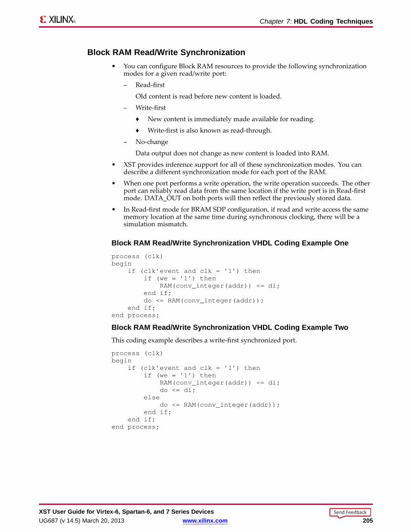
Chapter 7: HDL Coding Techniques
Bloc k RAM Read/Write Synchronization• You can configure Block RAM resources to provide the following synchronization
modes for a given read/write port:
– Read-first
Old content is read before new content is loaded.
– Write-first
♦ New content is immediately made available for reading.
♦ Write-first is also known as read-through.
– No-change
Data output does not change as new content is loaded into RAM.
• XST provides inference support for all of these synchronization modes. You candescribe a different synchronization mode for each port of the RAM.
• When one port performs a write operation, the write operation succeeds. The otherport can reliably read data from the same location if the write port is in Read-firstmode. DATA_OUT on both ports will then reflect the previously stored data.
• In Read-first mode for BRAM SDP configuration, if read and write access the samememory location at the same time during synchronous clocking, there will be asimulation mismatch.
Bloc k RAM Read/Write Synchronization VHDL Coding Example Oneprocess (clk)begin
if (clk’event and clk = ’1’) thenif (we = ’1’) then
RAM(conv_integer(addr)) <= di;end if;do <= RAM(conv_integer(addr));
end if;end process;
Bloc k RAM Read/Write Synchronization VHDL Coding Example TwoThis coding example describes a write-first synchronized port.
process (clk)begin
if (clk’event and clk = ’1’) thenif (we = ’1’) then
RAM(conv_integer(addr)) <= di;do <= di;
elsedo <= RAM(conv_integer(addr));
end if;end if;
end process;
XST User Guide for Vir tex-6, Spar tan-6, and 7 Series DevicesUG687 (v 14.5) March 20, 2013 www.xilinx.com 205
Send Feedback
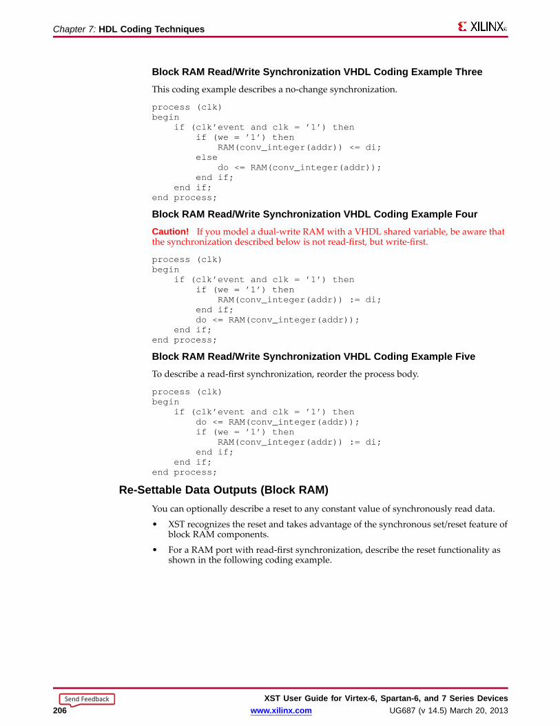
Chapter 7: HDL Coding Techniques
Bloc k RAM Read/Write Synchronization VHDL Coding Example ThreeThis coding example describes a no-change synchronization.
process (clk)begin
if (clk’event and clk = ’1’) thenif (we = ’1’) then
RAM(conv_integer(addr)) <= di;else
do <= RAM(conv_integer(addr));end if;
end if;end process;
Bloc k RAM Read/Write Synchronization VHDL Coding Example FourCaution! If you model a dual-write RAM with a VHDL shared variable, be aware thatthe synchronization described below is not read-first, but write-first.
process (clk)begin
if (clk’event and clk = ’1’) thenif (we = ’1’) then
RAM(conv_integer(addr)) := di;end if;do <= RAM(conv_integer(addr));
end if;end process;
Bloc k RAM Read/Write Synchronization VHDL Coding Example FiveTo describe a read-first synchronization, reorder the process body.
process (clk)begin
if (clk’event and clk = ’1’) thendo <= RAM(conv_integer(addr));if (we = ’1’) then
RAM(conv_integer(addr)) := di;end if;
end if;end process;
Re-Settab le Data Outputs (Bloc k RAM)You can optionally describe a reset to any constant value of synchronously read data.
• XST recognizes the reset and takes advantage of the synchronous set/reset feature ofblock RAM components.
• For a RAM port with read-first synchronization, describe the reset functionality asshown in the following coding example.
XST User Guide for Vir tex-6, Spar tan-6, and 7 Series Devices206 www.xilinx.com UG687 (v 14.5) March 20, 2013
Send Feedback
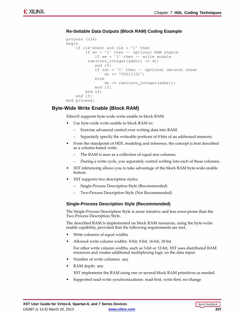
Chapter 7: HDL Coding Techniques
Re-Settab le Data Outputs (Bloc k RAM) Coding Exampleprocess (clk)begin
if clk’event and clk = ’1’ thenif en = ’1’ then -- optional RAMenable
if we = ’1’ then -- write enableram(conv_integer(addr)) <= di;
end if;if rst = ’1’ then -- optional dataout reset
do <= "00011101";else
do <= ram(conv_integer(addr));end if;
end if;end if;
end process;
Byte-Wide Write Enable (Bloc k RAM)Xilinx® supports byte-wide write enable in block RAM.
• Use byte-wide write enable in block RAM to:
– Exercise advanced control over writing data into RAM.
– Separately specify the writeable portions of 8 bits of an addressed memory.
• From the standpoint of HDL modeling and inference, the concept is best describedas a column-based write.
– The RAM is seen as a collection of equal size columns.
– During a write cycle, you separately control writing into each of these columns.
• XST inferencing allows you to take advantage of the block RAM byte-wide enablefeature.
• XST supports two description styles:
– Single-Process Description Style (Recommended)
– Two-Process Description Style (Not Recommended)
Single-Pr ocess Description Style (Recommended)The Single-Process Description Style is more intuitive and less error-prone than theTwo-Process Description Style.
The described RAM is implemented on block RAM resources, using the byte-writeenable capability, provided that the following requirements are met.
• Write columns of equal widths
• Allowed write column widths: 8-bit, 9-bit, 16-bit, 18-bit
For other write column widths, such as 5-bit or 12-bit, XST uses distributed RAMresources and creates additional multiplexing logic on the data input.
• Number of write columns: any
• RAM depth: any
XST implements the RAM using one or several block RAM primitives as needed.
• Supported read-write synchronizations: read-first, write-first, no-change
XST User Guide for Vir tex-6, Spar tan-6, and 7 Series DevicesUG687 (v 14.5) March 20, 2013 www.xilinx.com 207
Send Feedback
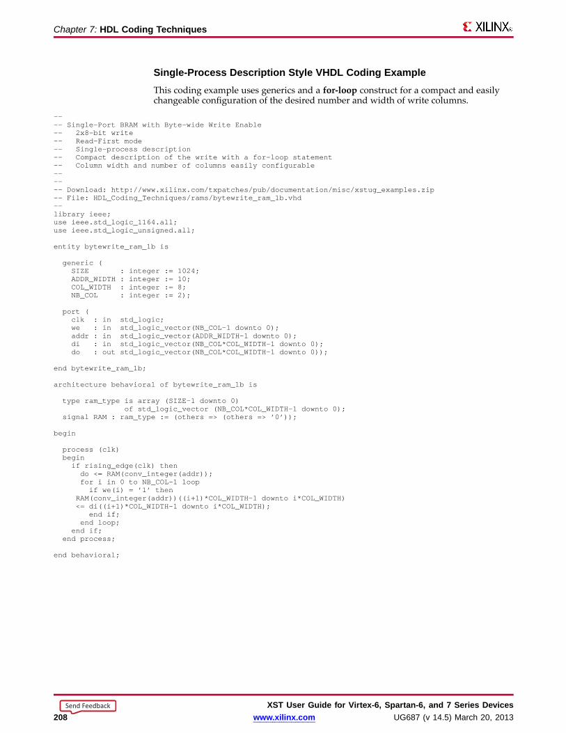
Chapter 7: HDL Coding Techniques
Single-Pr ocess Description Style VHDL Coding ExampleThis coding example uses generics and a for-loop construct for a compact and easilychangeable configuration of the desired number and width of write columns.
---- Single-Port BRAMwith Byte-wide Write Enable-- 2x8-bit write-- Read-First mode-- Single-process description-- Compact description of the write with a for-loop statement-- Column width and number of columns easily configurable------ Download: http://www.xilinx.com/txpatches/pub/documentation/misc/xstug_examples.zip-- File: HDL_Coding_Techniques/rams/bytewrite_ram_1b.vhd--library ieee;use ieee.std_logic_1164.all;use ieee.std_logic_unsigned.all;
entity bytewrite_ram_1b is
generic (SIZE : integer := 1024;ADDR_WIDTH: integer := 10;COL_WIDTH : integer := 8;NB_COL : integer := 2);
port (clk : in std_logic;we : in std_logic_vector(NB_COL-1 downto 0);addr : in std_logic_vector(ADDR_WIDTH-1 downto 0);di : in std_logic_vector(NB_COL*COL_WIDTH-1 downto 0);do : out std_logic_vector(NB_COL*COL_WIDTH-1 downto 0));
end bytewrite_ram_1b;
architecture behavioral of bytewrite_ram_1b is
type ram_type is array (SIZE-1 downto 0)of std_logic_vector (NB_COL*COL_WIDTH-1 downto 0);
signal RAM : ram_type := (others => (others => ’0’));
begin
process (clk)beginif rising_edge(clk) thendo <= RAM(conv_integer(addr));for i in 0 to NB_COL-1 loopif we(i) = ’1’ then
RAM(conv_integer(addr))((i+1)*COL_WIDTH-1 downto i*COL_WIDTH)<= di((i+1)*COL_WIDTH-1 downto i*COL_WIDTH);
end if;end loop;
end if;end process;
end behavioral;
XST User Guide for Vir tex-6, Spar tan-6, and 7 Series Devices208 www.xilinx.com UG687 (v 14.5) March 20, 2013
Send Feedback
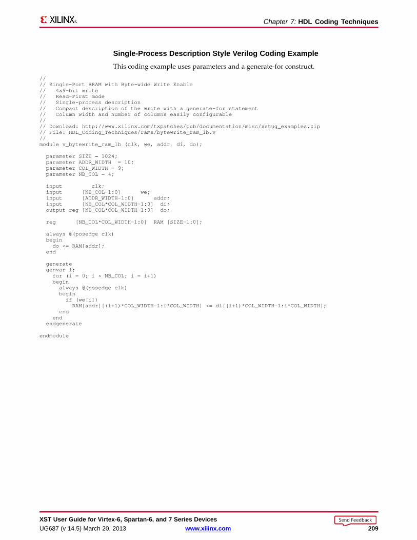
Chapter 7: HDL Coding Techniques
Single-Pr ocess Description Style Verilog Coding ExampleThis coding example uses parameters and a generate-for construct.
//// Single-Port BRAMwith Byte-wide Write Enable// 4x9-bit write// Read-First mode// Single-process description// Compact description of the write with a generate-for statement// Column width and number of columns easily configurable//// Download: http://www.xilinx.com/txpatches/pub/documentation/misc/xstug_examples.zip// File: HDL_Coding_Techniques/rams/bytewrite_ram_1b.v//module v_bytewrite_ram_1b (clk, we, addr, di, do);
parameter SIZE = 1024;parameter ADDR_WIDTH = 10;parameter COL_WIDTH= 9;parameter NB_COL = 4;
input clk;input [NB_COL-1:0] we;input [ADDR_WIDTH-1:0] addr;input [NB_COL*COL_WIDTH-1:0] di;output reg [NB_COL*COL_WIDTH-1:0] do;
reg [NB_COL*COL_WIDTH-1:0] RAM [SIZE-1:0];
always @(posedge clk)begindo <= RAM[addr];
end
generategenvar i;for (i = 0; i < NB_COL; i = i+1)beginalways @(posedge clk)beginif (we[i])RAM[addr][(i+1)*COL_WIDTH-1:i*COL_WIDTH] <= di[(i+1)*COL_WIDTH-1:i*COL_WIDTH];
endend
endgenerate
endmodule
XST User Guide for Vir tex-6, Spar tan-6, and 7 Series DevicesUG687 (v 14.5) March 20, 2013 www.xilinx.com 209
Send Feedback

Chapter 7: HDL Coding Techniques
Single-Pr ocess Description Style for No-Chang e VHDL Coding ExampleThe Single-Process Description Style is the only way to correctly model byte-writeenable functionality in conjunction with no-change read-write synchronization.
---- Single-Port BRAMwith Byte-wide Write Enable-- 2x8-bit write-- No-Change mode-- Single-process description-- Compact description of the write with a for-loop statement-- Column width and number of columns easily configurable------ Download: http://www.xilinx.com/txpatches/pub/documentation/misc/xstug_examples.zip-- File: HDL_Coding_Techniques/rams/bytewrite_nochange.vhd--library ieee;use ieee.std_logic_1164.all;use ieee.std_logic_unsigned.all;
entity bytewrite_nochange is
generic (SIZE : integer := 1024;ADDR_WIDTH: integer := 10;COL_WIDTH : integer := 8;NB_COL : integer := 2);
port (clk : in std_logic;we : in std_logic_vector(NB_COL-1 downto 0);addr : in std_logic_vector(ADDR_WIDTH-1 downto 0);di : in std_logic_vector(NB_COL*COL_WIDTH-1 downto 0);do : out std_logic_vector(NB_COL*COL_WIDTH-1 downto 0));
end bytewrite_nochange;
architecture behavioral of bytewrite_nochange is
type ram_type is array (SIZE-1 downto 0) of std_logic_vector (NB_COL*COL_WIDTH-1 downto 0);signal RAM : ram_type := (others => (others => ’0’));
begin
process (clk)beginif rising_edge(clk) thenif (we = (we’range => ’0’)) thendo <= RAM(conv_integer(addr));
end if;for i in 0 to NB_COL-1 loopif we(i) = ’1’ then
RAM(conv_integer(addr))((i+1)*COL_WIDTH-1 downto i*COL_WIDTH)<= di((i+1)*COL_WIDTH-1 downto i*COL_WIDTH);
end if;end loop;
end if;end process;
end behavioral;
XST User Guide for Vir tex-6, Spar tan-6, and 7 Series Devices210 www.xilinx.com UG687 (v 14.5) March 20, 2013
Send Feedback
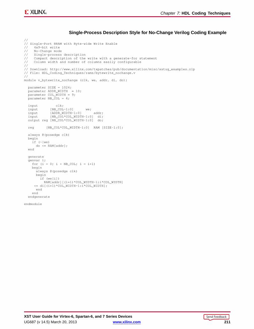
Chapter 7: HDL Coding Techniques
Single-Pr ocess Description Style for No-Chang e Verilog Coding Example//// Single-Port BRAMwith Byte-wide Write Enable// 4x9-bit write// No-Change mode// Single-process description// Compact description of the write with a generate-for statement// Column width and number of columns easily configurable//// Download: http://www.xilinx.com/txpatches/pub/documentation/misc/xstug_examples.zip// File: HDL_Coding_Techniques/rams/bytewrite_nochange.v//module v_bytewrite_nochange (clk, we, addr, di, do);
parameter SIZE = 1024;parameter ADDR_WIDTH = 10;parameter COL_WIDTH= 9;parameter NB_COL = 4;
input clk;input [NB_COL-1:0] we;input [ADDR_WIDTH-1:0] addr;input [NB_COL*COL_WIDTH-1:0] di;output reg [NB_COL*COL_WIDTH-1:0] do;
reg [NB_COL*COL_WIDTH-1:0] RAM [SIZE-1:0];
always @(posedge clk)beginif (~|we)do <= RAM[addr];
end
generategenvar i;for (i = 0; i < NB_COL; i = i+1)beginalways @(posedge clk)beginif (we[i])RAM[addr][(i+1)*COL_WIDTH-1:i*COL_WIDTH]
<= di[(i+1)*COL_WIDTH-1:i*COL_WIDTH];end
endendgenerate
endmodule
XST User Guide for Vir tex-6, Spar tan-6, and 7 Series DevicesUG687 (v 14.5) March 20, 2013 www.xilinx.com 211
Send Feedback
Chapter 7: HDL Coding Techniques
Two-Process Description StyleIn order to take advantage of block RAM byte-write enable capabilities, you mustprovide adequate data read synchronization. If you do not do so, XST implements thedescribed functionality sub-optimally, using distributed RAM resources instead.
• The Two-Process Description Style continues to be supported, but is no longerrecommended.
• The Two-Process Description Style does not allow you to properly describebyte-write enable functionality in conjunction with the no-change synchronizationmode.
• Xilinx recommends:
– If you currently use the Two-Process Description Style, change your design tothe Single-Process Description Style.
– Do not use the Two-Process Description Style for new designs.
• If you are unable to migrate your code to the Single-Process Description Style, XSTstill supports the Two-Process Description Style.
• In the Two-Process Description Style:
– A combinatorial process describes which data is loaded and read for each byte.In particular, the write enable functionality is described there, and not in themain sequential process.
– A sequential process describes the write and read synchronization.
– Data widths are more restrictive than with the Single-Process Description Style:
♦ Number of write columns: 2 or 4
♦ Write column widths: 8-bit or 9-bit
♦ Supported data widths: 2x8-bit (two columns of 8 bits each), 2x9-bit, 4x8-bit,4x9-bit
XST User Guide for Vir tex-6, Spar tan-6, and 7 Series Devices212 www.xilinx.com UG687 (v 14.5) March 20, 2013
Send Feedback

Chapter 7: HDL Coding Techniques
Two-Process Description Style VHDL Coding Example---- Single-Port BRAMwith Byte-wide Write Enable-- 2x8-bit write-- Read-First Mode-- Two-process description---- Download: http://www.xilinx.com/txpatches/pub/documentation/misc/xstug_examples.zip-- File: HDL_Coding_Techniques/rams/rams_24.vhd--library ieee;use ieee.std_logic_1164.all;use ieee.std_logic_unsigned.all;
entity rams_24 is
generic (SIZE : integer := 512;ADDR_WIDTH: integer := 9;COL_WIDTH : integer := 16;NB_COL : integer := 2);
port (clk : in std_logic;we : in std_logic_vector(NB_COL-1 downto 0);addr : in std_logic_vector(ADDR_WIDTH-1 downto 0);di : in std_logic_vector(NB_COL*COL_WIDTH-1 downto 0);do : out std_logic_vector(NB_COL*COL_WIDTH-1 downto 0));
end rams_24;
architecture syn of rams_24 is
type ram_type is array (SIZE-1 downto 0) of std_logic_vector (NB_COL*COL_WIDTH-1 downto 0);signal RAM : ram_type := (others => (others => ’0’));
signal di0, di1 : std_logic_vector (COL_WIDTH-1 downto 0);begin
process(we, di)begin
if we(1) = ’1’ thendi1 <= di(2*COL_WIDTH-1 downto 1*COL_WIDTH);
elsedi1 <= RAM(conv_integer(addr))(2*COL_WIDTH-1 downto 1*COL_WIDTH);
end if;
if we(0) = ’1’ thendi0 <= di(COL_WIDTH-1 downto 0);
elsedi0 <= RAM(conv_integer(addr))(COL_WIDTH-1 downto 0);
end if;end process;
process(clk)begin
if (clk’event and clk = ’1’) thendo <= RAM(conv_integer(addr));RAM(conv_integer(addr)) <= di1 & di0;
end if;end process;
end syn;
XST User Guide for Vir tex-6, Spar tan-6, and 7 Series DevicesUG687 (v 14.5) March 20, 2013 www.xilinx.com 213
Send Feedback

Chapter 7: HDL Coding Techniques
Two-Process Description Style Verilog Coding Example//// Single-Port BRAMwith Byte-wide Write Enable (2 bytes) in Read-First Mode//// Download: http://www.xilinx.com/txpatches/pub/documentation/misc/xstug_examples.zip// File: HDL_Coding_Techniques/rams/rams_24.v//module v_rams_24 (clk, we, addr, di, do);
parameter SIZE = 512;parameter ADDR_WIDTH= 9;parameter DI_WIDTH = 8;
input clk;input [1:0] we;input [ADDR_WIDTH-1:0] addr;input [2*DI_WIDTH-1:0] di;output [2*DI_WIDTH-1:0] do;reg [2*DI_WIDTH-1:0] RAM [SIZE-1:0];reg [2*DI_WIDTH-1:0] do;
reg [DI_WIDTH-1:0] di0, di1;
always @(we or di)begin
if (we[1])di1 = di[2*DI_WIDTH-1:1*DI_WIDTH];
elsedi1 = RAM[addr][2*DI_WIDTH-1:1*DI_WIDTH];
if (we[0])di0 = di[DI_WIDTH-1:0];
elsedi0 = RAM[addr][DI_WIDTH-1:0];
end
always @(posedge clk)begin
do <= RAM[addr];RAM[addr]<={di1,di0};
end
endmodule
XST User Guide for Vir tex-6, Spar tan-6, and 7 Series Devices214 www.xilinx.com UG687 (v 14.5) March 20, 2013
Send Feedback
Chapter 7: HDL Coding Techniques
Asymmetric Por ts Suppor t (Bloc k RAM)Block RAM resources can be configured with two asymmetric ports.
• Port A accesses the physical memory with a specific data width.
• Port B accesses the same physical memory with a different data width.
• Both ports access the same physical memory, but see a different logical organizationof the RAM. For example, the same 2048 bits of physical memory may be seen as:
– 256x8-bit by Port A
– 64x32-bit by Port B
• Such an asymmetrically configured block RAM is said to have ports with differentaspect ratios.
• A typical use of port asymmetry is to create storage and buffering between two dataflows. The data flows:
– Have different data width characteristics.
– Operate at asymmetric speeds.
Note Asymmetric RAM inference for data buses larger than 18-bit will require theRAMB36E1 block.
Bloc k RAM With Asymmetric Por ts ModelingLike RAM with no port asymmetry, block RAM with asymmetric ports is modeledwith a single array of array object.
• The depth and width characteristics of the modeling signal or shared variable matchthe RAM port with the lower data width (subsequently the larger depth).
• As a result of this modeling requirement, describing a read or write access for theport with the larger data width no longer implies one assignment, but severalassignments.
– The number of assignments equals the ratio between the two asymmetric datawidths.
– Each of these assignments may be explicitly described as illustrated in thefollowing coding examples.
XST User Guide for Vir tex-6, Spar tan-6, and 7 Series DevicesUG687 (v 14.5) March 20, 2013 www.xilinx.com 215
Send Feedback

Chapter 7: HDL Coding Techniques
Asymmetric Por t RAM VHDL Coding Example---- Asymmetric port RAM-- Port A is 256x8-bit write-only-- Port B is 64x32-bit read-only---- Download: http://www.xilinx.com/txpatches/pub/documentation/misc/xstug_examples.zip-- File: HDL_Coding_Techniques/rams/asymmetric_ram_1a.vhd--library ieee;use ieee.std_logic_1164.all;use ieee.std_logic_unsigned.all;use ieee.std_logic_arith.all;
entity asymmetric_ram_1a is
generic (WIDTHA : integer := 8;SIZEA : integer := 256;ADDRWIDTHA : integer := 8;WIDTHB : integer := 32;SIZEB : integer := 64;ADDRWIDTHB : integer := 6);
port (clkA : in std_logic;clkB : in std_logic;weA : in std_logic;enA : in std_logic;enB : in std_logic;addrA : in std_logic_vector(ADDRWIDTHA-1 downto 0);addrB : in std_logic_vector(ADDRWIDTHB-1 downto 0);diA : in std_logic_vector(WIDTHA-1 downto 0);doB : out std_logic_vector(WIDTHB-1 downto 0));
end asymmetric_ram_1a;
architecture behavioral of asymmetric_ram_1a is
function max(L, R: INTEGER) return INTEGER isbegin
if L > R thenreturn L;
elsereturn R;
end if;end;
function min(L, R: INTEGER) return INTEGER isbegin
if L < R thenreturn L;
elsereturn R;
end if;end;
constant minWIDTH : integer := min(WIDTHA,WIDTHB);constant maxWIDTH : integer := max(WIDTHA,WIDTHB);constant maxSIZE : integer := max(SIZEA,SIZEB);constant RATIO : integer := maxWIDTH / minWIDTH;
type ramType is array (0 to maxSIZE-1) of std_logic_vector(minWIDTH-1 downto 0);signal ram : ramType := (others => (others => ’0’));
signal readB : std_logic_vector(WIDTHB-1 downto 0):= (others => ’0’);signal regB : std_logic_vector(WIDTHB-1 downto 0):= (others => ’0’);
begin
XST User Guide for Vir tex-6, Spar tan-6, and 7 Series Devices216 www.xilinx.com UG687 (v 14.5) March 20, 2013
Send Feedback

Chapter 7: HDL Coding Techniques
process (clkA)beginif rising_edge(clkA) thenif enA = ’1’ thenif weA = ’1’ thenram(conv_integer(addrA)) <= diA;
end if;end if;
end if;end process;
process (clkB)beginif rising_edge(clkB) thenif enB = ’1’ thenreadB(minWIDTH-1 downto 0)
<= ram(conv_integer(addrB&conv_std_logic_vector(0,2)));readB(2*minWIDTH-1 downto minWIDTH)
<= ram(conv_integer(addrB&conv_std_logic_vector(1,2)));readB(3*minWIDTH-1 downto 2*minWIDTH)
<= ram(conv_integer(addrB&conv_std_logic_vector(2,2)));readB(4*minWIDTH-1 downto 3*minWIDTH)
<= ram(conv_integer(addrB&conv_std_logic_vector(3,2)));end if;regB <= readB;
end if;end process;
doB <= regB;
end behavioral;
XST User Guide for Vir tex-6, Spar tan-6, and 7 Series DevicesUG687 (v 14.5) March 20, 2013 www.xilinx.com 217
Send Feedback
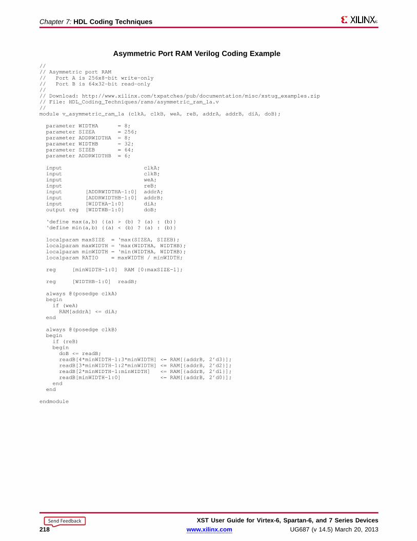
Chapter 7: HDL Coding Techniques
Asymmetric Por t RAM Verilog Coding Example//// Asymmetric port RAM// Port A is 256x8-bit write-only// Port B is 64x32-bit read-only//// Download: http://www.xilinx.com/txpatches/pub/documentation/misc/xstug_examples.zip// File: HDL_Coding_Techniques/rams/asymmetric_ram_1a.v//module v_asymmetric_ram_1a (clkA, clkB, weA, reB, addrA, addrB, diA, doB);
parameter WIDTHA = 8;parameter SIZEA = 256;parameter ADDRWIDTHA = 8;parameter WIDTHB = 32;parameter SIZEB = 64;parameter ADDRWIDTHB = 6;
input clkA;input clkB;input weA;input reB;input [ADDRWIDTHA-1:0] addrA;input [ADDRWIDTHB-1:0] addrB;input [WIDTHA-1:0] diA;output reg [WIDTHB-1:0] doB;
‘define max(a,b) {(a) > (b) ? (a) : (b)}‘define min(a,b) {(a) < (b) ? (a) : (b)}
localparam maxSIZE = ‘max(SIZEA, SIZEB);localparam maxWIDTH = ‘max(WIDTHA, WIDTHB);localparam minWIDTH = ‘min(WIDTHA, WIDTHB);localparam RATIO = maxWIDTH / minWIDTH;
reg [minWIDTH-1:0] RAM [0:maxSIZE-1];
reg [WIDTHB-1:0] readB;
always @(posedge clkA)beginif (weA)RAM[addrA] <= diA;
end
always @(posedge clkB)beginif (reB)begindoB <= readB;readB[4*minWIDTH-1:3*minWIDTH] <= RAM[{addrB, 2’d3}];readB[3*minWIDTH-1:2*minWIDTH] <= RAM[{addrB, 2’d2}];readB[2*minWIDTH-1:minWIDTH] <= RAM[{addrB, 2’d1}];readB[minWIDTH-1:0] <= RAM[{addrB, 2’d0}];
endend
endmodule
XST User Guide for Vir tex-6, Spar tan-6, and 7 Series Devices218 www.xilinx.com UG687 (v 14.5) March 20, 2013
Send Feedback
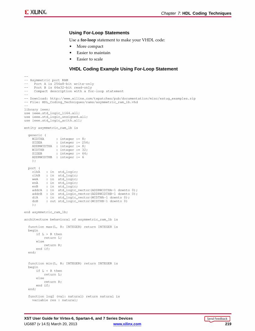
Chapter 7: HDL Coding Techniques
Using For-Loop StatementsUse a for-loop statement to make your VHDL code:• More compact• Easier to maintain• Easier to scale
VHDL Coding Example Using For-Loop Statement---- Asymmetric port RAM-- Port A is 256x8-bit write-only-- Port B is 64x32-bit read-only-- Compact description with a for-loop statement---- Download: http://www.xilinx.com/txpatches/pub/documentation/misc/xstug_examples.zip-- File: HDL_Coding_Techniques/rams/asymmetric_ram_1b.vhd--library ieee;use ieee.std_logic_1164.all;use ieee.std_logic_unsigned.all;use ieee.std_logic_arith.all;
entity asymmetric_ram_1b is
generic (WIDTHA : integer := 8;SIZEA : integer := 256;ADDRWIDTHA : integer := 8;WIDTHB : integer := 32;SIZEB : integer := 64;ADDRWIDTHB : integer := 6);
port (clkA : in std_logic;clkB : in std_logic;weA : in std_logic;enA : in std_logic;enB : in std_logic;addrA : in std_logic_vector(ADDRWIDTHA-1 downto 0);addrB : in std_logic_vector(ADDRWIDTHB-1 downto 0);diA : in std_logic_vector(WIDTHA-1 downto 0);doB : out std_logic_vector(WIDTHB-1 downto 0));
end asymmetric_ram_1b;
architecture behavioral of asymmetric_ram_1b is
function max(L, R: INTEGER) return INTEGER isbegin
if L > R thenreturn L;
elsereturn R;
end if;end;
function min(L, R: INTEGER) return INTEGER isbegin
if L < R thenreturn L;
elsereturn R;
end if;end;
function log2 (val: natural) return natural isvariable res : natural;
XST User Guide for Vir tex-6, Spar tan-6, and 7 Series DevicesUG687 (v 14.5) March 20, 2013 www.xilinx.com 219
Send Feedback

Chapter 7: HDL Coding Techniques
beginfor i in 30 downto 0 loop
if (val >= (2**i)) thenres := i;exit;
end if;end loop;return res;
end function log2;
constant minWIDTH : integer := min(WIDTHA,WIDTHB);constant maxWIDTH : integer := max(WIDTHA,WIDTHB);constant maxSIZE : integer := max(SIZEA,SIZEB);constant RATIO : integer := maxWIDTH / minWIDTH;
type ramType is array (0 to maxSIZE-1) of std_logic_vector(minWIDTH-1 downto 0);signal ram : ramType := (others => (others => ’0’));
signal readB : std_logic_vector(WIDTHB-1 downto 0):= (others => ’0’);signal regB : std_logic_vector(WIDTHB-1 downto 0):= (others => ’0’);
begin
process (clkA)beginif rising_edge(clkA) thenif enA = ’1’ thenif weA = ’1’ thenram(conv_integer(addrA)) <= diA;
end if;end if;
end if;
end process;
process (clkB)beginif rising_edge(clkB) thenif enB = ’1’ thenfor i in 0 to RATIO-1 loopreadB((i+1)*minWIDTH-1 downto i*minWIDTH)
<= ram(conv_integer(addrB & conv_std_logic_vector(i,log2(RATIO))));end loop;
end if;regB <= readB;
end if;end process;
doB <= regB;
end behavioral;
Verilog Coding Example Using Parameter s and Generate-For StatementUse parameters and a generate-for statement to make your Verilog code:• More compact• Easier to modify
//// Asymmetric port RAM// Port A is 256x8-bit write-only// Port B is 64x32-bit read-only//// Download: http://www.xilinx.com/txpatches/pub/documentation/misc/xstug_examples.zip// File: HDL_Coding_Techniques/rams/v_asymmetric_ram_1b.v//module v_asymmetric_ram_1b (clkA, clkB, weA, reB, addrA, addrB, diA, doB);
parameter WIDTHA = 8;parameter SIZEA = 256;parameter ADDRWIDTHA = 8;
XST User Guide for Vir tex-6, Spar tan-6, and 7 Series Devices220 www.xilinx.com UG687 (v 14.5) March 20, 2013
Send Feedback

Chapter 7: HDL Coding Techniques
parameter WIDTHB = 32;parameter SIZEB = 64;parameter ADDRWIDTHB = 6;
input clkA;input clkB;input weA;input reB;input [ADDRWIDTHA-1:0] addrA;input [ADDRWIDTHB-1:0] addrB;input [WIDTHA-1:0] diA;output reg [WIDTHB-1:0] doB;
‘define max(a,b) {(a) > (b) ? (a) : (b)}‘define min(a,b) {(a) < (b) ? (a) : (b)}
function integer log2;input integer value;reg [31:0] shifted;integer res;
beginif (value < 2)log2 = value;
elsebeginshifted = value-1;for (res=0; shifted>0; res=res+1)shifted = shifted>>1;
log2 = res;end
endendfunction
localparam maxSIZE = ‘max(SIZEA, SIZEB);localparam maxWIDTH = ‘max(WIDTHA, WIDTHB);localparam minWIDTH = ‘min(WIDTHA, WIDTHB);localparam RATIO = maxWIDTH / minWIDTH;localparam log2RATIO = log2(RATIO);
reg [minWIDTH-1:0] RAM [0:maxSIZE-1];
reg [WIDTHB-1:0] readB;
genvar i;
always @(posedge clkA)beginif (weA)RAM[addrA] <= diA;
end
always @(posedge clkB)beginif (reB)doB <= readB;
end
generate for (i = 0; i < RATIO; i = i+1)begin: ramreadlocalparam [log2RATIO-1:0] lsbaddr = i;always @(posedge clkB)beginreadB[(i+1)*minWIDTH-1:i*minWIDTH] <= RAM[{addrB, lsbaddr}];
endend
endgenerate
endmodule
Note These coding examples use min, max, and log2 functions to make the code asgeneric and clean as possible. Those functions can be defined anywhere in the design,typically in a package.
XST User Guide for Vir tex-6, Spar tan-6, and 7 Series DevicesUG687 (v 14.5) March 20, 2013 www.xilinx.com 221
Send Feedback

Chapter 7: HDL Coding Techniques
Shared Variab le (VHDL)• When you describe a symmetric port RAM in VHDL, a shared variable is required
only if you describe two ports writing into the RAM. Otherwise, a signal is preferred.• When you describe an asymmetric port RAM in VHDL, a shared variable may be
required even if only one write port is described. If the write port has the larger datawidth, several write assignments are needed to describe it, and a shared variable istherefore required as shown in the following coding example.
Shared Variab le Required VHDL Coding Example---- Asymmetric port RAM-- Port A is 256x8-bit read-only-- Port B is 64x32-bit write-only-- Compact description with a for-loop statement-- A shared variable is necessary because of the multiple write assignments---- Download: http://www.xilinx.com/txpatches/pub/documentation/misc/xstug_examples.zip-- File: HDL_Coding_Techniques/rams/asymmetric_ram_4.vhd--library ieee;use ieee.std_logic_1164.all;use ieee.std_logic_unsigned.all;use ieee.std_logic_arith.all;
entity asymmetric_ram_4 is
generic (WIDTHA : integer := 8;SIZEA : integer := 256;ADDRWIDTHA : integer := 8;WIDTHB : integer := 32;SIZEB : integer := 64;ADDRWIDTHB : integer := 6);
port (clkA : in std_logic;clkB : in std_logic;reA : in std_logic;weB : in std_logic;addrA : in std_logic_vector(ADDRWIDTHA-1 downto 0);addrB : in std_logic_vector(ADDRWIDTHB-1 downto 0);diB : in std_logic_vector(WIDTHB-1 downto 0);doA : out std_logic_vector(WIDTHA-1 downto 0));
end asymmetric_ram_4;
architecture behavioral of asymmetric_ram_4 is
function max(L, R: INTEGER) return INTEGER isbegin
if L > R thenreturn L;
elsereturn R;
end if;end;
function min(L, R: INTEGER) return INTEGER isbegin
if L < R thenreturn L;
elsereturn R;
end if;end;
XST User Guide for Vir tex-6, Spar tan-6, and 7 Series Devices222 www.xilinx.com UG687 (v 14.5) March 20, 2013
Send Feedback
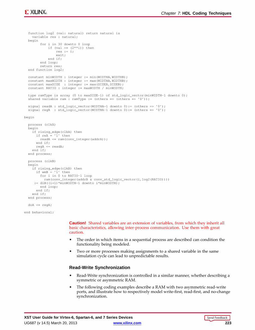
Chapter 7: HDL Coding Techniques
function log2 (val: natural) return natural isvariable res : natural;
beginfor i in 30 downto 0 loop
if (val >= (2**i)) thenres := i;exit;
end if;end loop;return res;
end function log2;
constant minWIDTH : integer := min(WIDTHA,WIDTHB);constant maxWIDTH : integer := max(WIDTHA,WIDTHB);constant maxSIZE : integer := max(SIZEA,SIZEB);constant RATIO : integer := maxWIDTH / minWIDTH;
type ramType is array (0 to maxSIZE-1) of std_logic_vector(minWIDTH-1 downto 0);shared variable ram : ramType := (others => (others => ’0’));
signal readA : std_logic_vector(WIDTHA-1 downto 0):= (others => ’0’);signal regA : std_logic_vector(WIDTHA-1 downto 0):= (others => ’0’);
begin
process (clkA)beginif rising_edge(clkA) thenif reA = ’1’ thenreadA <= ram(conv_integer(addrA));
end if;regA <= readA;
end if;end process;
process (clkB)beginif rising_edge(clkB) thenif weB = ’1’ thenfor i in 0 to RATIO-1 loopram(conv_integer(addrB & conv_std_logic_vector(i,log2(RATIO))))
:= diB((i+1)*minWIDTH-1 downto i*minWIDTH);end loop;
end if;end if;
end process;
doA <= regA;
end behavioral;
Caution! Shared variables are an extension of variables, from which they inherit allbasic characteristics, allowing inter-process communication. Use them with greatcaution.
• The order in which items in a sequential process are described can condition thefunctionality being modeled.
• Two or more processes making assignments to a shared variable in the samesimulation cycle can lead to unpredictable results.
Read-Write Synchronization• Read-Write synchronization is controlled in a similar manner, whether describing a
symmetric or asymmetric RAM.
• The following coding examples describe a RAM with two asymmetric read-writeports, and illustrate how to respectively model write-first, read-first, and no-changesynchronization.
XST User Guide for Vir tex-6, Spar tan-6, and 7 Series DevicesUG687 (v 14.5) March 20, 2013 www.xilinx.com 223
Send Feedback

Chapter 7: HDL Coding Techniques
Asymmetric Por t RAM (Write-Fir st) VHDL Coding Example---- Asymmetric port RAM-- Port A is 256x8-bit read-and-write (write-first synchronization)-- Port B is 64x32-bit read-and-write (write-first synchronization)-- Compact description with a for-loop statement---- Download: http://www.xilinx.com/txpatches/pub/documentation/misc/xstug_examples.zip-- File: HDL_Coding_Techniques/rams/asymmetric_ram_2b.vhd--library ieee;use ieee.std_logic_1164.all;use ieee.std_logic_unsigned.all;use ieee.std_logic_arith.all;
entity asymmetric_ram_2b is
generic (WIDTHA : integer := 8;SIZEA : integer := 256;ADDRWIDTHA : integer := 8;WIDTHB : integer := 32;SIZEB : integer := 64;ADDRWIDTHB : integer := 6);
port (clkA : in std_logic;clkB : in std_logic;enA : in std_logic;enB : in std_logic;weA : in std_logic;weB : in std_logic;addrA : in std_logic_vector(ADDRWIDTHA-1 downto 0);addrB : in std_logic_vector(ADDRWIDTHB-1 downto 0);diA : in std_logic_vector(WIDTHA-1 downto 0);diB : in std_logic_vector(WIDTHB-1 downto 0);doA : out std_logic_vector(WIDTHA-1 downto 0);doB : out std_logic_vector(WIDTHB-1 downto 0));
end asymmetric_ram_2b;
architecture behavioral of asymmetric_ram_2b is
function max(L, R: INTEGER) return INTEGER isbegin
if L > R thenreturn L;
elsereturn R;
end if;end;
function min(L, R: INTEGER) return INTEGER isbegin
if L < R thenreturn L;
elsereturn R;
end if;end;
function log2 (val: natural) return natural isvariable res : natural;
beginfor i in 30 downto 0 loop
if (val >= (2**i)) thenres := i;exit;
end if;
XST User Guide for Vir tex-6, Spar tan-6, and 7 Series Devices224 www.xilinx.com UG687 (v 14.5) March 20, 2013
Send Feedback
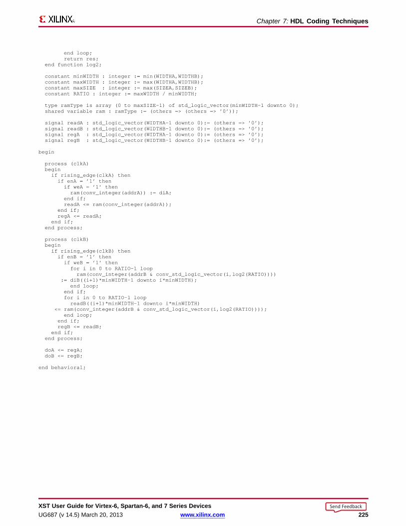
Chapter 7: HDL Coding Techniques
end loop;return res;
end function log2;
constant minWIDTH : integer := min(WIDTHA,WIDTHB);constant maxWIDTH : integer := max(WIDTHA,WIDTHB);constant maxSIZE : integer := max(SIZEA,SIZEB);constant RATIO : integer := maxWIDTH / minWIDTH;
type ramType is array (0 to maxSIZE-1) of std_logic_vector(minWIDTH-1 downto 0);shared variable ram : ramType := (others => (others => ’0’));
signal readA : std_logic_vector(WIDTHA-1 downto 0):= (others => ’0’);signal readB : std_logic_vector(WIDTHB-1 downto 0):= (others => ’0’);signal regA : std_logic_vector(WIDTHA-1 downto 0):= (others => ’0’);signal regB : std_logic_vector(WIDTHB-1 downto 0):= (others => ’0’);
begin
process (clkA)beginif rising_edge(clkA) thenif enA = ’1’ thenif weA = ’1’ thenram(conv_integer(addrA)) := diA;
end if;readA <= ram(conv_integer(addrA));
end if;regA <= readA;
end if;end process;
process (clkB)beginif rising_edge(clkB) thenif enB = ’1’ thenif weB = ’1’ thenfor i in 0 to RATIO-1 loopram(conv_integer(addrB & conv_std_logic_vector(i,log2(RATIO))))
:= diB((i+1)*minWIDTH-1 downto i*minWIDTH);end loop;
end if;for i in 0 to RATIO-1 loopreadB((i+1)*minWIDTH-1 downto i*minWIDTH)
<= ram(conv_integer(addrB & conv_std_logic_vector(i,log2(RATIO))));end loop;
end if;regB <= readB;
end if;end process;
doA <= regA;doB <= regB;
end behavioral;
XST User Guide for Vir tex-6, Spar tan-6, and 7 Series DevicesUG687 (v 14.5) March 20, 2013 www.xilinx.com 225
Send Feedback

Chapter 7: HDL Coding Techniques
Asymmetric Por t RAM (Read-Fir st) VHDL Coding Example---- Asymmetric port RAM-- Port A is 256x8-bit read-and-write (read-first synchronization)-- Port B is 64x32-bit read-and-write (read-first synchronization)-- Compact description with a for-loop statement---- Download: http://www.xilinx.com/txpatches/pub/documentation/misc/xstug_examples.zip-- File: HDL_Coding_Techniques/rams/asymmetric_ram_2c.vhd--library ieee;use ieee.std_logic_1164.all;use ieee.std_logic_unsigned.all;use ieee.std_logic_arith.all;
entity asymmetric_ram_2c is
generic (WIDTHA : integer := 8;SIZEA : integer := 256;ADDRWIDTHA : integer := 8;WIDTHB : integer := 32;SIZEB : integer := 64;ADDRWIDTHB : integer := 6);
port (clkA : in std_logic;clkB : in std_logic;enA : in std_logic;enB : in std_logic;weA : in std_logic;weB : in std_logic;addrA : in std_logic_vector(ADDRWIDTHA-1 downto 0);addrB : in std_logic_vector(ADDRWIDTHB-1 downto 0);diA : in std_logic_vector(WIDTHA-1 downto 0);diB : in std_logic_vector(WIDTHB-1 downto 0);doA : out std_logic_vector(WIDTHA-1 downto 0);doB : out std_logic_vector(WIDTHB-1 downto 0));
end asymmetric_ram_2c;
architecture behavioral of asymmetric_ram_2c is
function max(L, R: INTEGER) return INTEGER isbegin
if L > R thenreturn L;
elsereturn R;
end if;end;
function min(L, R: INTEGER) return INTEGER isbegin
if L < R thenreturn L;
elsereturn R;
end if;end;
function log2 (val: natural) return natural isvariable res : natural;
beginfor i in 30 downto 0 loop
if (val >= (2**i)) thenres := i;exit;
end if;
XST User Guide for Vir tex-6, Spar tan-6, and 7 Series Devices226 www.xilinx.com UG687 (v 14.5) March 20, 2013
Send Feedback

Chapter 7: HDL Coding Techniques
end loop;return res;
end function log2;
constant minWIDTH : integer := min(WIDTHA,WIDTHB);constant maxWIDTH : integer := max(WIDTHA,WIDTHB);constant maxSIZE : integer := max(SIZEA,SIZEB);constant RATIO : integer := maxWIDTH / minWIDTH;
type ramType is array (0 to maxSIZE-1) of std_logic_vector(minWIDTH-1 downto 0);shared variable ram : ramType := (others => (others => ’0’));
signal readA : std_logic_vector(WIDTHA-1 downto 0):= (others => ’0’);signal readB : std_logic_vector(WIDTHB-1 downto 0):= (others => ’0’);signal regA : std_logic_vector(WIDTHA-1 downto 0):= (others => ’0’);signal regB : std_logic_vector(WIDTHB-1 downto 0):= (others => ’0’);
begin
process (clkA)beginif rising_edge(clkA) thenif enA = ’1’ thenreadA <= ram(conv_integer(addrA));if weA = ’1’ thenram(conv_integer(addrA)) := diA;
end if;end if;regA <= readA;
end if;end process;
process (clkB)beginif rising_edge(clkB) thenif enB = ’1’ thenfor i in 0 to RATIO-1 loopreadB((i+1)*minWIDTH-1 downto i*minWIDTH)
<= ram(conv_integer(addrB & conv_std_logic_vector(i,log2(RATIO))));end loop;if weB = ’1’ thenfor i in 0 to RATIO-1 loopram(conv_integer(addrB & conv_std_logic_vector(i,log2(RATIO))))
:= diB((i+1)*minWIDTH-1 downto i*minWIDTH);end loop;
end if;end if;regB <= readB;
end if;end process;
doA <= regA;doB <= regB;
end behavioral;
XST User Guide for Vir tex-6, Spar tan-6, and 7 Series DevicesUG687 (v 14.5) March 20, 2013 www.xilinx.com 227
Send Feedback

Chapter 7: HDL Coding Techniques
Asymmetric Por t RAM (No-Chang e) VHDL Coding Example---- Asymmetric port RAM-- Port A is 256x8-bit read-and-write (no-change synchronization)-- Port B is 64x32-bit read-and-write (no-change synchronization)-- Compact description with a for-loop statement---- Download: http://www.xilinx.com/txpatches/pub/documentation/misc/xstug_examples.zip-- File: HDL_Coding_Techniques/rams/asymmetric_ram_2d.vhd--library ieee;use ieee.std_logic_1164.all;use ieee.std_logic_unsigned.all;use ieee.std_logic_arith.all;
entity asymmetric_ram_2d is
generic (WIDTHA : integer := 8;SIZEA : integer := 256;ADDRWIDTHA : integer := 8;WIDTHB : integer := 32;SIZEB : integer := 64;ADDRWIDTHB : integer := 6);
port (clkA : in std_logic;clkB : in std_logic;enA : in std_logic;enB : in std_logic;weA : in std_logic;weB : in std_logic;addrA : in std_logic_vector(ADDRWIDTHA-1 downto 0);addrB : in std_logic_vector(ADDRWIDTHB-1 downto 0);diA : in std_logic_vector(WIDTHA-1 downto 0);diB : in std_logic_vector(WIDTHB-1 downto 0);doA : out std_logic_vector(WIDTHA-1 downto 0);doB : out std_logic_vector(WIDTHB-1 downto 0));
end asymmetric_ram_2d;
architecture behavioral of asymmetric_ram_2d is
function max(L, R: INTEGER) return INTEGER isbegin
if L > R thenreturn L;
elsereturn R;
end if;end;
function min(L, R: INTEGER) return INTEGER isbegin
if L < R thenreturn L;
elsereturn R;
end if;end;
function log2 (val: natural) return natural isvariable res : natural;
beginfor i in 30 downto 0 loop
if (val >= (2**i)) thenres := i;exit;
end if;
XST User Guide for Vir tex-6, Spar tan-6, and 7 Series Devices228 www.xilinx.com UG687 (v 14.5) March 20, 2013
Send Feedback
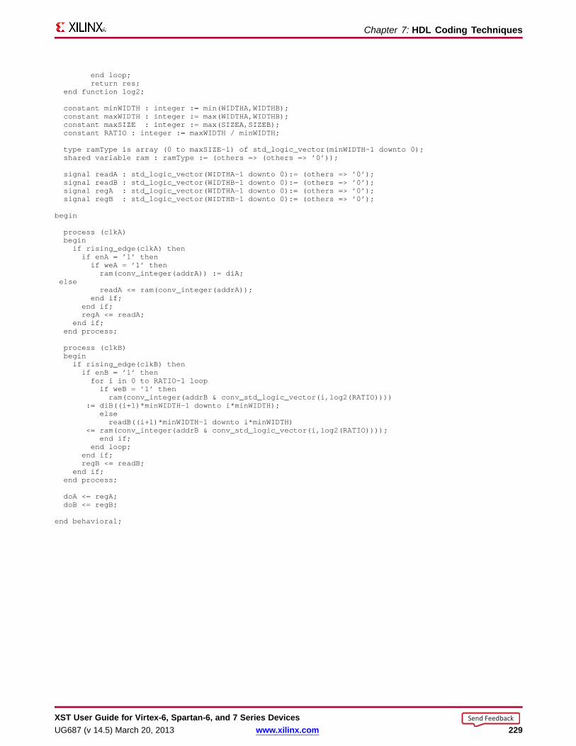
Chapter 7: HDL Coding Techniques
end loop;return res;
end function log2;
constant minWIDTH : integer := min(WIDTHA,WIDTHB);constant maxWIDTH : integer := max(WIDTHA,WIDTHB);constant maxSIZE : integer := max(SIZEA,SIZEB);constant RATIO : integer := maxWIDTH / minWIDTH;
type ramType is array (0 to maxSIZE-1) of std_logic_vector(minWIDTH-1 downto 0);shared variable ram : ramType := (others => (others => ’0’));
signal readA : std_logic_vector(WIDTHA-1 downto 0):= (others => ’0’);signal readB : std_logic_vector(WIDTHB-1 downto 0):= (others => ’0’);signal regA : std_logic_vector(WIDTHA-1 downto 0):= (others => ’0’);signal regB : std_logic_vector(WIDTHB-1 downto 0):= (others => ’0’);
begin
process (clkA)beginif rising_edge(clkA) thenif enA = ’1’ thenif weA = ’1’ thenram(conv_integer(addrA)) := diA;
elsereadA <= ram(conv_integer(addrA));
end if;end if;regA <= readA;
end if;end process;
process (clkB)beginif rising_edge(clkB) thenif enB = ’1’ thenfor i in 0 to RATIO-1 loopif weB = ’1’ thenram(conv_integer(addrB & conv_std_logic_vector(i,log2(RATIO))))
:= diB((i+1)*minWIDTH-1 downto i*minWIDTH);elsereadB((i+1)*minWIDTH-1 downto i*minWIDTH)
<= ram(conv_integer(addrB & conv_std_logic_vector(i,log2(RATIO))));end if;
end loop;end if;regB <= readB;
end if;end process;
doA <= regA;doB <= regB;
end behavioral;
XST User Guide for Vir tex-6, Spar tan-6, and 7 Series DevicesUG687 (v 14.5) March 20, 2013 www.xilinx.com 229
Send Feedback

Chapter 7: HDL Coding Techniques
Parity BitsFor asymmetric port RAMs, XST can take advantage of the available block RAM paritybits to implement extra data bits for word sizes of 9, 18 and 36 bits.
Asymmetric Por t RAM (Parity Bits) VHDL Coding Example---- Asymmetric port RAM-- Port A is 2048x18-bit write-only-- Port B is 4096x9-bit read-only-- XST uses parity bits to accomodate data widths---- Download: http://www.xilinx.com/txpatches/pub/documentation/misc/xstug_examples.zip-- File: HDL_Coding_Techniques/rams/asymmetric_ram_3.vhd--library ieee;use ieee.std_logic_1164.all;use ieee.std_logic_unsigned.all;use ieee.std_logic_arith.all;
entity asymmetric_ram_3 is
generic (WIDTHA : integer := 18;SIZEA : integer := 2048;ADDRWIDTHA : integer := 11;WIDTHB : integer := 9;SIZEB : integer := 4096;ADDRWIDTHB : integer := 12);
port (clkA : in std_logic;clkB : in std_logic;weA : in std_logic;reB : in std_logic;addrA : in std_logic_vector(ADDRWIDTHA-1 downto 0);addrB : in std_logic_vector(ADDRWIDTHB-1 downto 0);diA : in std_logic_vector(WIDTHA-1 downto 0);doB : out std_logic_vector(WIDTHB-1 downto 0));
end asymmetric_ram_3;
architecture behavioral of asymmetric_ram_3 is
function max(L, R: INTEGER) return INTEGER isbegin
if L > R thenreturn L;
elsereturn R;
end if;end;
function min(L, R: INTEGER) return INTEGER isbegin
if L < R thenreturn L;
elsereturn R;
end if;end;
function log2 (val: natural) return natural isvariable res : natural;
beginfor i in 30 downto 0 loop
if (val >= (2**i)) thenres := i;exit;
XST User Guide for Vir tex-6, Spar tan-6, and 7 Series Devices230 www.xilinx.com UG687 (v 14.5) March 20, 2013
Send Feedback
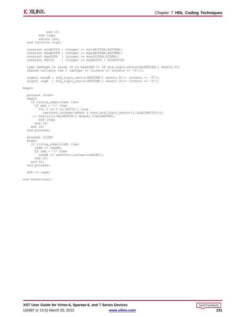
Chapter 7: HDL Coding Techniques
end if;end loop;return res;
end function log2;
constant minWIDTH : integer := min(WIDTHA,WIDTHB);constant maxWIDTH : integer := max(WIDTHA,WIDTHB);constant maxSIZE : integer := max(SIZEA,SIZEB);constant RATIO : integer := maxWIDTH / minWIDTH;
type ramType is array (0 to maxSIZE-1) of std_logic_vector(minWIDTH-1 downto 0);shared variable ram : ramType := (others => (others => ’0’));
signal readB : std_logic_vector(WIDTHB-1 downto 0):= (others => ’0’);signal regB : std_logic_vector(WIDTHB-1 downto 0):= (others => ’0’);
begin
process (clkA)beginif rising_edge(clkA) thenif weA = ’1’ thenfor i in 0 to RATIO-1 loopram(conv_integer(addrA & conv_std_logic_vector(i,log2(RATIO))))
:= diA((i+1)*minWIDTH-1 downto i*minWIDTH);end loop;
end if;end if;
end process;
process (clkB)beginif rising_edge(clkB) thenregB <= readB;if reB = ’1’ thenreadB <= ram(conv_integer(addrB));
end if;end if;
end process;
doB <= regB;
end behavioral;
XST User Guide for Vir tex-6, Spar tan-6, and 7 Series DevicesUG687 (v 14.5) March 20, 2013 www.xilinx.com 231
Send Feedback
Chapter 7: HDL Coding Techniques
Asymmetric Por ts GuidelinesFollow these guidelines to ensure that the synthesized solution is implementedoptimally on dedicated block RAM resources.
• Support for port asymmetry is available only if the described RAM can beimplemented on block RAM resources. Be sure to provide adequate data readsynchronization.
• Port asymmetry is supported only if the described RAM fits in a single block RAMprimitive.
• If the described asymmetric port RAM does not fit in a single block RAM primitive,you must manually instantiate the desired device primitives.
• If XST cannot use asymmetrically-configured block RAM resources, the describedRAM is implemented on LUT resources, giving suboptimal results and a significantincrease in runtime.
• The amount of memory accessible from both ports must match exactly.
Example Do not try to describe a port which sees the RAM as a 256x8-bit (2048 bitsof memory), while the other port sees the RAM as a 64x12-bit (768 bits of memory).
• The ratio between both data widths is a power of two. .
• The ratio between both port depths is a power of two.
XST User Guide for Vir tex-6, Spar tan-6, and 7 Series Devices232 www.xilinx.com UG687 (v 14.5) March 20, 2013
Send Feedback

Chapter 7: HDL Coding Techniques
Asymmetric Por ts Repor ting Example=========================================================================* HDL Synthesis *=========================================================================
Synthesizing Unit <asymmetric_ram_1a>.Found 256x8:64x32-bit dual-port RAM<Mram_ram> for signal <ram>.Found 32-bit register for signal <doB>.Found 32-bit register for signal <readB>.Summary:inferred 1 RAM(s).inferred 64 D-type flip-flop(s).
Unit <asymmetric_ram_1a> synthesized.
=========================================================================HDL Synthesis Report
Macro Statistics# RAMs : 1256x8:64x32-bit dual-port RAM : 1# Registers : 232-bit register : 2
=========================================================================
=========================================================================* Advanced HDL Synthesis *=========================================================================
Synthesizing (advanced) Unit <asymmetric_ram_1a>.INFO:Xst - The RAM<Mram_ram> will be implemented as a BLOCKRAM,absorbing the following register(s): <readB> <doB>
-----------------------------------------------------------------------| ram_type | Block | |-----------------------------------------------------------------------| Port A || aspect ratio | 256-word x 8-bit | || mode | read-first | || clkA | connected to signal <clkA> | rise || weA | connected to signal <weA_0> | high || addrA | connected to signal <addrA> | || diA | connected to signal <diA> | |-----------------------------------------------------------------------| optimization | speed | |-----------------------------------------------------------------------| Port B || aspect ratio | 64-word x 32-bit | || mode | write-first | || clkB | connected to signal <clkB> | rise || enB | connected to signal <enB> | high || addrB | connected to signal <addrB> | || doB | connected to signal <doB> | |-----------------------------------------------------------------------| optimization | speed | |-----------------------------------------------------------------------
Unit <asymmetric_ram_1a> synthesized (advanced).
=========================================================================Advanced HDL Synthesis Report
Macro Statistics# RAMs : 1256x8:64x32-bit dual-port block RAM : 1
=========================================================================
…
XST User Guide for Vir tex-6, Spar tan-6, and 7 Series DevicesUG687 (v 14.5) March 20, 2013 www.xilinx.com 233
Send Feedback

Chapter 7: HDL Coding Techniques
RAM Initial ContentsTasks in RAM Initial Contents include:
• Specifying RAM Initial Contents in the HDL Source Code
• Specifying RAM Initial Contents in an External Data File
Specifying RAM Initial Contents in the HDL Sour ce CodeUse the signal default value mechanism to describe initial RAM contents directly in theHDL source code.
VHDL Coding Example Onetype ram_type is array (0 to 31) of std_logic_vector(19 downto 0);signal RAM : ram_type :=(
X"0200A", X"00300", X"08101", X"04000", X"08601", X"0233A", X"00300", X"08602",X"02310", X"0203B", X"08300", X"04002", X"08201", X"00500", X"04001", X"02500",X"00340", X"00241", X"04002", X"08300", X"08201", X"00500", X"08101", X"00602",X"04003", X"0241E", X"00301", X"00102", X"02122", X"02021", X"0030D", X"08201"
);
VHDL Coding Example TwoAll addressable words are initialized to the same value.
type ram_type is array (0 to 127) of std_logic_vector (15 downto 0);signal RAM : ram_type := (others => "0000111100110101");
VHDL Coding Example ThreeAll bit positions are initialized to the same value.
type ram_type is array (0 to 127) of std_logic_vector (15 downto 0);signal RAM : ram_type := (others => (others => ’1’));
VHDL Coding Example FourParticular values are selectively defined for specific address positions or ranges.
type ram_type is array (255 downto 0) of std_logic_vector (15 downto 0);signal RAM : ram_type:= (
196 downto 110 => X"B8B8",100 => X"FEFC"99 downto 0 => X"8282",others => X"3344");
Verilog Coding Example OneUse an initial block.
reg [19:0] ram [31:0];
initial beginram[31] = 20’h0200A; ram[30] = 20’h00300; ram[39] = 20’h08101;(...)ram[2] = 20’h02341; ram[1] = 20’h08201; ram[0] = 20’h0400D;
end
Verilog Coding Example TwoAll addressable words are initialized to the same value.
Reg [DATA_WIDTH-1:0] ram [DEPTH-1:0];
integer i;initial for (i=0; i<DEPTH; i=i+1) ram[i] = 0;
XST User Guide for Vir tex-6, Spar tan-6, and 7 Series Devices234 www.xilinx.com UG687 (v 14.5) March 20, 2013
Send Feedback

Chapter 7: HDL Coding Techniques
Verilog Coding Example ThreeSpecific address positions or address ranges are initialized.
reg [15:0] ram [255:0];
integer index;initial begin
for (index = 0 ; index <= 97 ; index = index + 1)ram[index] = 16’h8282;
ram[98] <= 16’h1111;ram[99] <= 16’h7778;for (index = 100 ; index <= 255 ; index = index + 1)
ram[index] = 16’hB8B8;end
Specifying RAM Initial Contents in an External Data File• Use the file read function in the HDL source code to load the RAM initial contents
from an external data file.– The external data file is an ASCII text file with any name.– Each line in the external data file describes the initial content at an address
position in the RAM.– There must be as many lines in the external data file as there are rows in the
RAM array. An insufficient number of lines is flagged.– The addressable position related to a given line is defined by the direction of
the primary range of the signal modeling the RAM.– You can represent RAM content in either binary or hexadecimal. You cannot
mix both.– The external data file cannot contain any other content, such as comments.
• The following external data file initializes an 8 x 32-bit RAM with binary values:
0000111100001111000011110000111101001010001000001100000010000100000000000011111000000000010000011111110101000001110001000010010000001111000011110000111100001111010010100010000011000000100001000000000000111110000000000100000111111101010000011100010000100100
• For more information, see:– VHDL File Type Support– Chapter 5, Behavioral Verilog
VHDL Coding ExampleLoad the data as follows.
type RamType is array(0 to 127) of bit_vector(31 downto 0);
impure function InitRamFromFile (RamFileName : in string) return RamType isFILE RamFile : text is in RamFileName;variable RamFileLine : line;variable RAM : RamType;
beginfor I in RamType’range loop
readline (RamFile, RamFileLine);read (RamFileLine, RAM(I));
end loop;return RAM;
end function;
signal RAM : RamType := InitRamFromFile("rams_20c.data");
XST User Guide for Vir tex-6, Spar tan-6, and 7 Series DevicesUG687 (v 14.5) March 20, 2013 www.xilinx.com 235
Send Feedback

Chapter 7: HDL Coding Techniques
Verilog Coding ExampleUse a $readmemb or $readmemh system task to load respectively binary-formatted orhexadecimal data.
reg [31:0] ram [0:63];
initial begin$readmemb("rams_20c.data", ram, 0, 63);
end
XST User Guide for Vir tex-6, Spar tan-6, and 7 Series Devices236 www.xilinx.com UG687 (v 14.5) March 20, 2013
Send Feedback
Chapter 7: HDL Coding Techniques
Bloc k RAM Optimization Strategies• When an inferred RAM macro does not fit in a single block RAM, you may choose
among several methods to partition it onto several block RAM components.• Depending on your choice, the number of block RAM primitives and the amount
of surrounding logic will vary.• These variations lead to different optimization trade-offs among performance,
device utilization, and power.
Bloc k RAM Performance• The default block RAM implementation strategy attempts to maximize performance.• XST does not try to achieve the minimum theoretical number of block RAM
primitives for a given RAM size requiring multiple block RAM primitives.• Implementing small RAM components on block resources often does not lead to
optimal performance.• Block RAM resources can be used for small RAM components at the expense of
much larger macros.• XST implements small RAM components on distributed resources in order to
achieve better design performance.• For more information, see Rules for Small RAM Components.
Bloc k RAM Device Utilization• XST does not support area-oriented block RAM implementation.• Use the CORE Generator™ software for area-oriented implementation.• For more information, see Chapter 8, FPGA Optimization.
Bloc k RAM Power ReductionTechniques to reduce block RAM power dissipation:• Are part of a larger set of optimizations controlled by the Power Reduction
constraint.• Are enabled by the RAM Style constraint.• Are primarily aimed at reducing the number of simultaneously-active block RAM
components.• Apply only to inferred memories that:
– Require a decomposition on several block RAM primitives, and– Take advantage of the enable capability of block RAM resources.
• Have no effect on an inferred memory that fits in single block RAM primitive.
Additional Enable LogicXST creates additional enable logic to ensure that only one block RAM primitive issimultaneously enabled to implement an inferred memory. This additional enable logicseeks to:• Reduce power• Optimize area• Optimize speed
XST User Guide for Vir tex-6, Spar tan-6, and 7 Series DevicesUG687 (v 14.5) March 20, 2013 www.xilinx.com 237
Send Feedback

Chapter 7: HDL Coding Techniques
Optimization Trade-OffsThe RAM Style constraint makes two optimization trade-offs available:
• block_power1
• block_power2
block_power1
• Achieves some degree of power reduction.
• May minimally impact power depending on memory characteristics.
• Minimally impacts performance.
• Uses the default block RAM decomposition method. This method:
– Is performance-oriented.
– Adds block RAM enable logic.
block_power2
• Provides more significant power reduction.
• May leave some performance capability unused.
• May induce additional slice logic.
• Uses a different block RAM decomposition method from block_power1.
– Attempts to reduce the number of block RAM primitives required to implementan inferred memory. This method:
– Inserts block RAM enable logic in order to minimize the number of active blockRAM components.
– Creates multiplexing logic to read the data from active block RAM components.
Use block_power2 if:
• Your primary concern is power reduction, and
• You are willing to give up some degree of speed and area optimization.
Summar y of Comparison Between block_power1 and block_power2block_power1 bloc k_power2
Power Reduction • Achieves some degree of powerreduction.
• May minimally impact powerdepending on memorycharacteristics.
Provides more significant powerreduction.
Performance Minimally impacts performance. May leave some performance capabilityunused.
block RAM decomposition method Uses the default block RAMdecomposition method.
Uses a different block RAMdecomposition method.
XST User Guide for Vir tex-6, Spar tan-6, and 7 Series Devices238 www.xilinx.com UG687 (v 14.5) March 20, 2013
Send Feedback
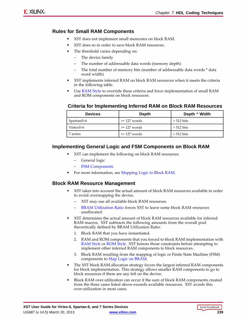
Chapter 7: HDL Coding Techniques
Rules for Small RAM Components• XST does not implement small memories on block RAM.• XST does so in order to save block RAM resources.• The threshold varies depending on:
– The device family– The number of addressable data words (memory depth)– The total number of memory bits (number of addressable data words * data
word width)• XST implements inferred RAM on block RAM resources when it meets the criteria
in the following table.• Use RAM Style to override these criteria and force implementation of small RAM
and ROM components on block resources.
Criteria for Implementing Inferred RAM on Bloc k RAM Resour cesDevices Depth Depth * Width
Spartan®-6 >= 127 words > 512 bits
Virtex®-6 >= 127 words > 512 bits
7 series >= 127 words > 512 bits
Implementing General Logic and FSM Components on Bloc k RAM• XST can implement the following on block RAM resources:
– General logic– FSM Components
• For more information, see Mapping Logic to Block RAM.
Bloc k RAM Resour ce Management• XST takes into account the actual amount of block RAM resources available in order
to avoid overmapping the device.– XST may use all available block RAM resources.– BRAM Utilization Ratio forces XST to leave some block RAM resources
unallocated.• XST determines the actual amount of block RAM resources available for inferred
RAM macros. XST subtracts the following amounts from the overall pooltheoretically defined by BRAM Utilization Ratio:1. Block RAM that you have instantiated.2. RAM and ROM components that you forced to block RAM implementation with
RAM Style or ROM Style. XST honors those constraints before attempting toimplement other inferred RAM components to block resources.
3. Block RAM resulting from the mapping of logic or Finite State Machine (FSM)components to Map Logic on BRAM.
• The XST block RAM allocation strategy favors the largest inferred RAM componentsfor block implementation. This strategy allows smaller RAM components to go toblock resources if there are any left on the device.
• Block RAM over-utilization can occur if the sum of block RAM components createdfrom the three cases listed above exceeds available resources. XST avoids thisover-utilization in most cases.
XST User Guide for Vir tex-6, Spar tan-6, and 7 Series DevicesUG687 (v 14.5) March 20, 2013 www.xilinx.com 239
Send Feedback

Chapter 7: HDL Coding Techniques
Bloc k RAM Packing• XST can implement additional RAM on block resources by packing small single-port
RAM components together.
• XST can implement two single-port RAM components on a single dual-port blockRAM primitive. Each port manages a physically distinct part of the block RAM.
• This optimization is controlled by Automatic BRAM Packing, and is disabled bydefault.
Distrib uted RAM Pipelining• XST can pipeline RAM components implemented on distributed resources.
– There must be an adequate number of latency stages.
– The effect of pipelining is similar to Flip-Flop Retiming.
– The result is increased performance.
• To insert pipeline stages:
1. Describe the necessary number of Registers in the HDL source code.
2. Place the Registers after the RAM.
3. Set RAM Style to pipe_distributed.
• During pipelining:
– XST calculates the ideal number of Register stages needed to maximizeoperating frequency.
– XST issues an HDL Advisor message if there are fewer than the ideal number ofRegister stages. The message reports the number of additional Register stagesneeded to achieve the ideal number.
– XST cannot pipeline distributed RAM components if the Registers haveasynchronous set or reset logic.
– XST can pipeline RAM components if Registers contain synchronous resetsignals.
RAM Related Constraints• The RAM related constraints are:
– RAM Extraction
– RAM Style
– ROM Extraction
– ROM Style
– BRAM Utilization Ratio
– Automatic BRAM Packing
• XST accepts LOC and RLOC on inferred RAM implemented in a single block RAMprimitive.
• LOC and RLOC are propagated to the NGC netlist.
XST User Guide for Vir tex-6, Spar tan-6, and 7 Series Devices240 www.xilinx.com UG687 (v 14.5) March 20, 2013
Send Feedback

Chapter 7: HDL Coding Techniques
RAM Repor ting• XST provides detailed information on inferred RAM, including:
– Size
– Synchronization
– Control signals
• RAM recognition consists of two steps:
1. HDL Synthesis
XST recognizes the presence of the memory structure in the HDL source code.
2. Advanced HDL Synthesis
After acquiring a more accurate picture of each RAM component, XSTimplements them on distributed or block RAM resources, depending onresource availability.
• An inferred block RAM is generally reported as shown in the following example.
XST User Guide for Vir tex-6, Spar tan-6, and 7 Series DevicesUG687 (v 14.5) March 20, 2013 www.xilinx.com 241
Send Feedback
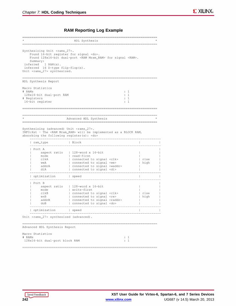
Chapter 7: HDL Coding Techniques
RAM Repor ting Log Example=========================================================================* HDL Synthesis *=========================================================================
Synthesizing Unit <rams_27>.Found 16-bit register for signal <do>.Found 128x16-bit dual-port <RAMMram_RAM>for signal <RAM>.Summary:
inferred 1 RAM(s).inferred 16 D-type flip-flop(s).Unit <rams_27> synthesized.
=========================================================================HDL Synthesis Report
Macro Statistics# RAMs : 1128x16-bit dual-port RAM : 1# Registers : 116-bit register : 1
=========================================================================
=========================================================================* Advanced HDL Synthesis *=========================================================================
Synthesizing (advanced) Unit <rams_27>.INFO:Xst - The <RAMMram_RAM>will be implemented as a BLOCKRAM,absorbing the following register(s): <do>
-----------------------------------------------------------------------| ram_type | Block | |-----------------------------------------------------------------------| Port A || aspect ratio | 128-word x 16-bit | || mode | read-first | || clkA | connected to signal <clk> | rise || weA | connected to signal <we> | high || addrA | connected to signal <waddr> | || diA | connected to signal <di> | |-----------------------------------------------------------------------| optimization | speed | |-----------------------------------------------------------------------| Port B || aspect ratio | 128-word x 16-bit | || mode | write-first | || clkB | connected to signal <clk> | rise || enB | connected to signal <re> | high || addrB | connected to signal <raddr> | || doB | connected to signal <do> | |-----------------------------------------------------------------------| optimization | speed | |-----------------------------------------------------------------------
Unit <rams_27> synthesized (advanced).
=========================================================================Advanced HDL Synthesis Report
Macro Statistics# RAMs : 1128x16-bit dual-port block RAM : 1
=========================================================================
XST User Guide for Vir tex-6, Spar tan-6, and 7 Series Devices242 www.xilinx.com UG687 (v 14.5) March 20, 2013
Send Feedback

Chapter 7: HDL Coding Techniques
Pipelining of Distrib uted RAM Repor ting Log ExamplePipelining of a distributed RAM results in the following specific reporting in theAdvanced HDL Synthesis section.
Synthesizing (advanced) Unit <v_rams_22>.Found pipelined ram on signal <n0006>:- 1 pipeline level(s) found in a register on signal <n0006>.Pushing register(s) into the ram macro.
INFO:Xst:2390 - HDL ADVISOR - You can improve the performance of the ram Mram_RAMby adding 1 register level(s) on output signal n0006.Unit <v_rams_22> synthesized (advanced).
RAM Coding ExamplesFor update information, see “Coding Examples” in the Introduction.
Single-P or t RAM with Async hronous Read (Distrib uted RAM) VHDL CodingExample
---- Single-Port RAMwith Asynchronous Read (Distributed RAM)---- Download: http://www.xilinx.com/txpatches/pub/documentation/misc/xstug_examples.zip-- File: HDL_Coding_Techniques/rams/rams_04.vhd--library ieee;use ieee.std_logic_1164.all;use ieee.std_logic_unsigned.all;
entity rams_04 isport (clk : in std_logic;
we : in std_logic;a : in std_logic_vector(5 downto 0);di : in std_logic_vector(15 downto 0);do : out std_logic_vector(15 downto 0));
end rams_04;
architecture syn of rams_04 istype ram_type is array (63 downto 0) of std_logic_vector (15 downto 0);signal RAM : ram_type;
begin
process (clk)begin
if (clk’event and clk = ’1’) thenif (we = ’1’) then
RAM(conv_integer(a)) <= di;end if;
end if;end process;
do <= RAM(conv_integer(a));
end syn;
XST User Guide for Vir tex-6, Spar tan-6, and 7 Series DevicesUG687 (v 14.5) March 20, 2013 www.xilinx.com 243
Send Feedback
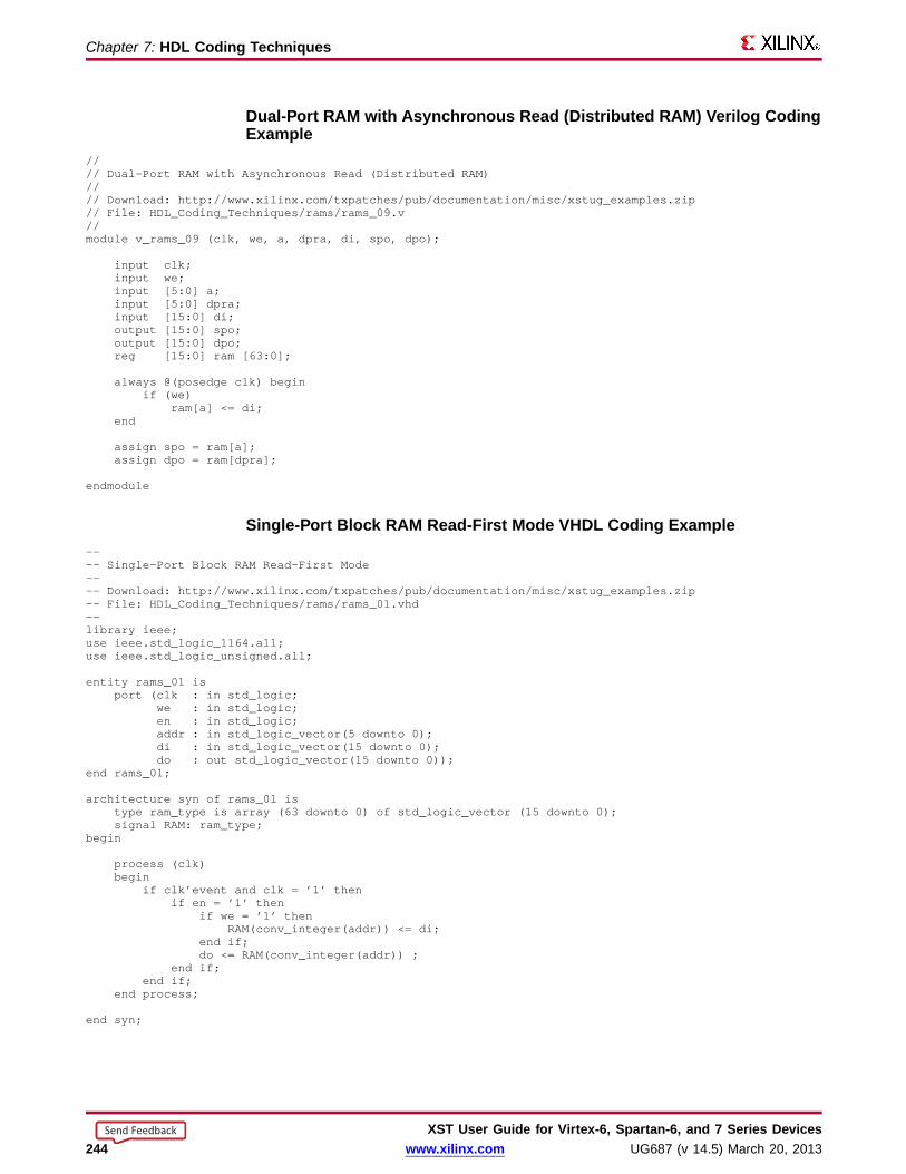
Chapter 7: HDL Coding Techniques
Dual-Por t RAM with Async hronous Read (Distrib uted RAM) Verilog CodingExample
//// Dual-Port RAMwith Asynchronous Read (Distributed RAM)//// Download: http://www.xilinx.com/txpatches/pub/documentation/misc/xstug_examples.zip// File: HDL_Coding_Techniques/rams/rams_09.v//module v_rams_09 (clk, we, a, dpra, di, spo, dpo);
input clk;input we;input [5:0] a;input [5:0] dpra;input [15:0] di;output [15:0] spo;output [15:0] dpo;reg [15:0] ram [63:0];
always @(posedge clk) beginif (we)
ram[a] <= di;end
assign spo = ram[a];assign dpo = ram[dpra];
endmodule
Single-P or t Bloc k RAM Read-Fir st Mode VHDL Coding Example---- Single-Port Block RAMRead-First Mode---- Download: http://www.xilinx.com/txpatches/pub/documentation/misc/xstug_examples.zip-- File: HDL_Coding_Techniques/rams/rams_01.vhd--library ieee;use ieee.std_logic_1164.all;use ieee.std_logic_unsigned.all;
entity rams_01 isport (clk : in std_logic;
we : in std_logic;en : in std_logic;addr : in std_logic_vector(5 downto 0);di : in std_logic_vector(15 downto 0);do : out std_logic_vector(15 downto 0));
end rams_01;
architecture syn of rams_01 istype ram_type is array (63 downto 0) of std_logic_vector (15 downto 0);signal RAM: ram_type;
begin
process (clk)begin
if clk’event and clk = ’1’ thenif en = ’1’ then
if we = ’1’ thenRAM(conv_integer(addr)) <= di;
end if;do <= RAM(conv_integer(addr)) ;
end if;end if;
end process;
end syn;
XST User Guide for Vir tex-6, Spar tan-6, and 7 Series Devices244 www.xilinx.com UG687 (v 14.5) March 20, 2013
Send Feedback
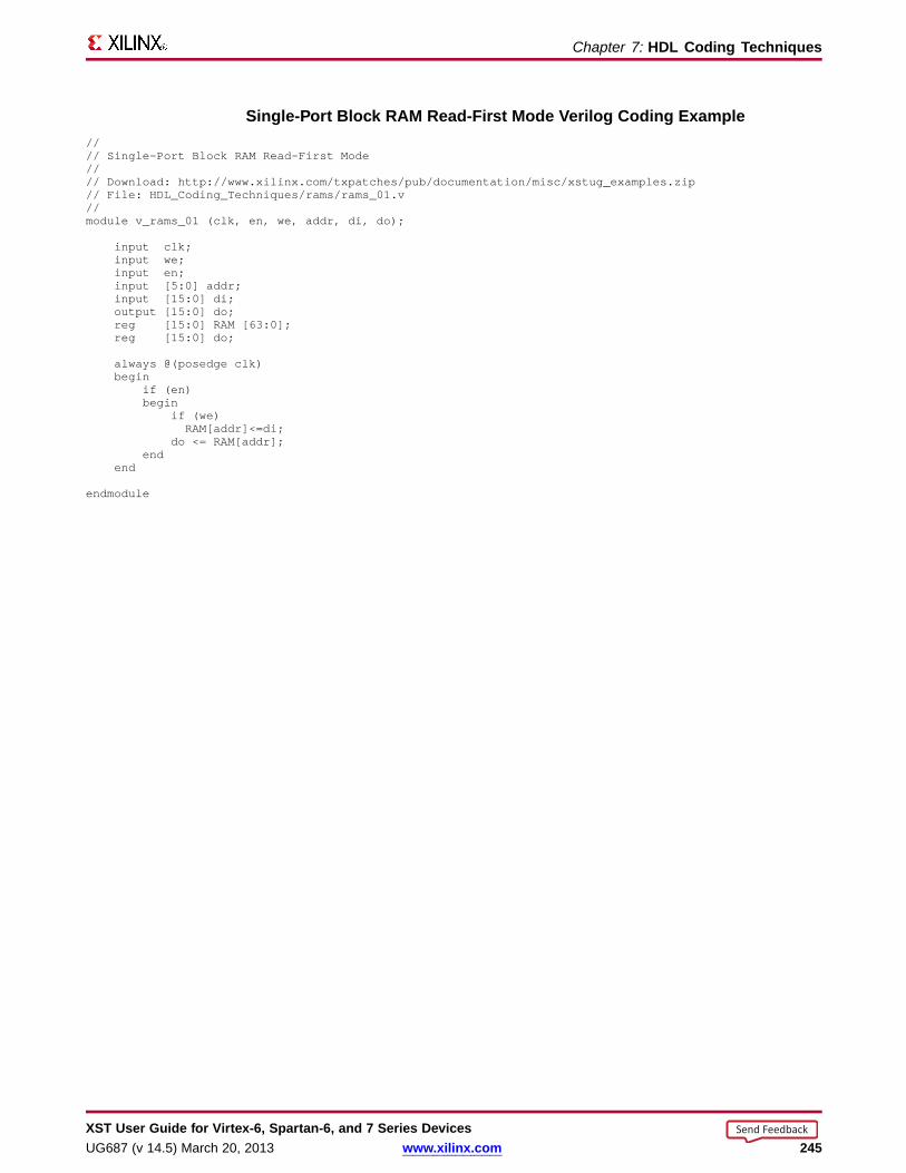
Chapter 7: HDL Coding Techniques
Single-P or t Bloc k RAM Read-Fir st Mode Verilog Coding Example//// Single-Port Block RAMRead-First Mode//// Download: http://www.xilinx.com/txpatches/pub/documentation/misc/xstug_examples.zip// File: HDL_Coding_Techniques/rams/rams_01.v//module v_rams_01 (clk, en, we, addr, di, do);
input clk;input we;input en;input [5:0] addr;input [15:0] di;output [15:0] do;reg [15:0] RAM [63:0];reg [15:0] do;
always @(posedge clk)begin
if (en)begin
if (we)RAM[addr]<=di;
do <= RAM[addr];end
end
endmodule
XST User Guide for Vir tex-6, Spar tan-6, and 7 Series DevicesUG687 (v 14.5) March 20, 2013 www.xilinx.com 245
Send Feedback
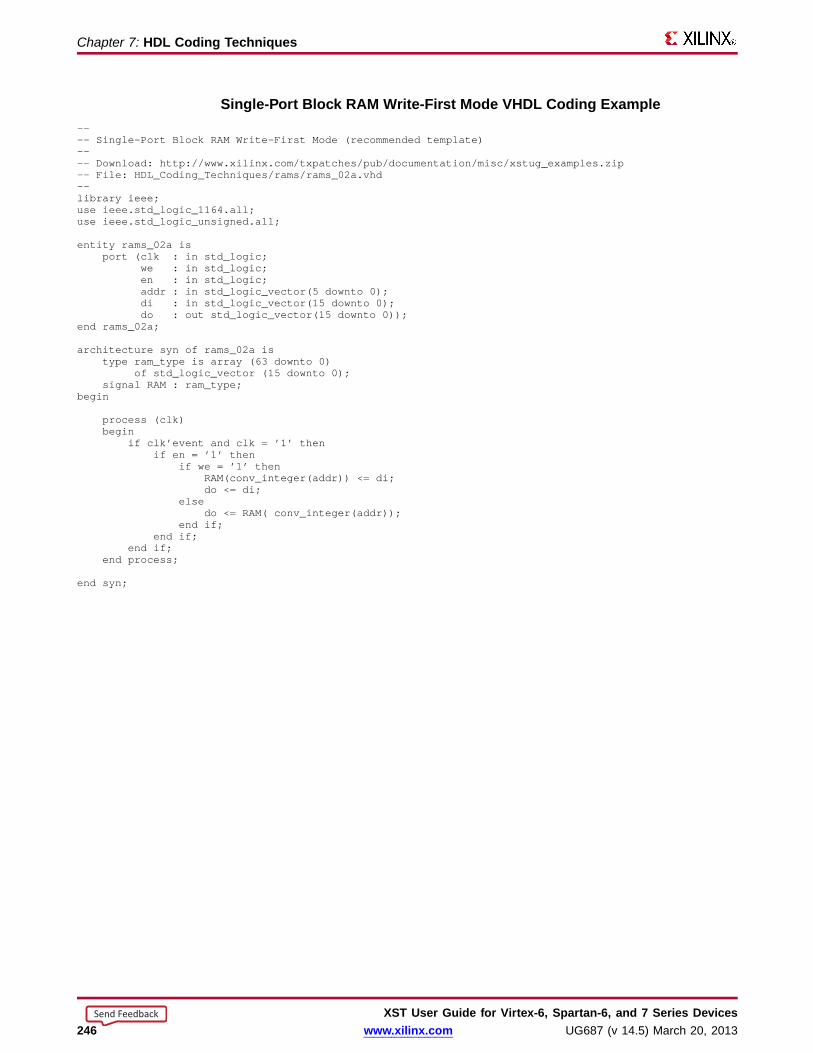
Chapter 7: HDL Coding Techniques
Single-P or t Bloc k RAM Write-Fir st Mode VHDL Coding Example---- Single-Port Block RAMWrite-First Mode (recommended template)---- Download: http://www.xilinx.com/txpatches/pub/documentation/misc/xstug_examples.zip-- File: HDL_Coding_Techniques/rams/rams_02a.vhd--library ieee;use ieee.std_logic_1164.all;use ieee.std_logic_unsigned.all;
entity rams_02a isport (clk : in std_logic;
we : in std_logic;en : in std_logic;addr : in std_logic_vector(5 downto 0);di : in std_logic_vector(15 downto 0);do : out std_logic_vector(15 downto 0));
end rams_02a;
architecture syn of rams_02a istype ram_type is array (63 downto 0)
of std_logic_vector (15 downto 0);signal RAM : ram_type;
begin
process (clk)begin
if clk’event and clk = ’1’ thenif en = ’1’ then
if we = ’1’ thenRAM(conv_integer(addr)) <= di;do <= di;
elsedo <= RAM( conv_integer(addr));
end if;end if;
end if;end process;
end syn;
XST User Guide for Vir tex-6, Spar tan-6, and 7 Series Devices246 www.xilinx.com UG687 (v 14.5) March 20, 2013
Send Feedback
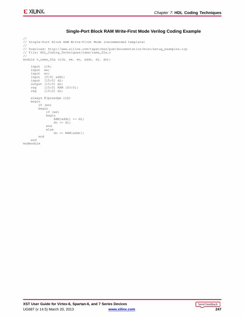
Chapter 7: HDL Coding Techniques
Single-P or t Bloc k RAM Write-Fir st Mode Verilog Coding Example//// Single-Port Block RAMWrite-First Mode (recommended template)//// Download: http://www.xilinx.com/txpatches/pub/documentation/misc/xstug_examples.zip// File: HDL_Coding_Techniques/rams/rams_02a.v//module v_rams_02a (clk, we, en, addr, di, do);
input clk;input we;input en;input [5:0] addr;input [15:0] di;output [15:0] do;reg [15:0] RAM [63:0];reg [15:0] do;
always @(posedge clk)begin
if (en)begin
if (we)begin
RAM[addr] <= di;do <= di;
endelse
do <= RAM[addr];end
endendmodule
XST User Guide for Vir tex-6, Spar tan-6, and 7 Series DevicesUG687 (v 14.5) March 20, 2013 www.xilinx.com 247
Send Feedback
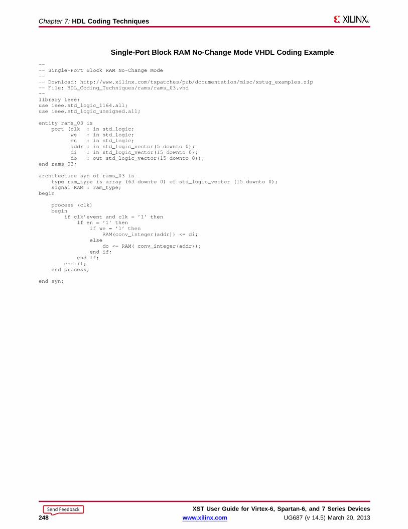
Chapter 7: HDL Coding Techniques
Single-P or t Bloc k RAM No-Chang e Mode VHDL Coding Example---- Single-Port Block RAMNo-Change Mode---- Download: http://www.xilinx.com/txpatches/pub/documentation/misc/xstug_examples.zip-- File: HDL_Coding_Techniques/rams/rams_03.vhd--library ieee;use ieee.std_logic_1164.all;use ieee.std_logic_unsigned.all;
entity rams_03 isport (clk : in std_logic;
we : in std_logic;en : in std_logic;addr : in std_logic_vector(5 downto 0);di : in std_logic_vector(15 downto 0);do : out std_logic_vector(15 downto 0));
end rams_03;
architecture syn of rams_03 istype ram_type is array (63 downto 0) of std_logic_vector (15 downto 0);signal RAM : ram_type;
begin
process (clk)begin
if clk’event and clk = ’1’ thenif en = ’1’ then
if we = ’1’ thenRAM(conv_integer(addr)) <= di;
elsedo <= RAM( conv_integer(addr));
end if;end if;
end if;end process;
end syn;
XST User Guide for Vir tex-6, Spar tan-6, and 7 Series Devices248 www.xilinx.com UG687 (v 14.5) March 20, 2013
Send Feedback
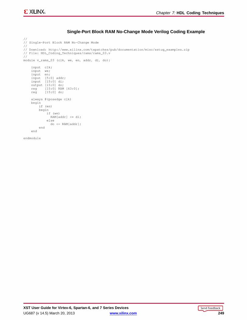
Chapter 7: HDL Coding Techniques
Single-P or t Bloc k RAM No-Chang e Mode Verilog Coding Example//// Single-Port Block RAMNo-Change Mode//// Download: http://www.xilinx.com/txpatches/pub/documentation/misc/xstug_examples.zip// File: HDL_Coding_Techniques/rams/rams_03.v//module v_rams_03 (clk, we, en, addr, di, do);
input clk;input we;input en;input [5:0] addr;input [15:0] di;output [15:0] do;reg [15:0] RAM [63:0];reg [15:0] do;
always @(posedge clk)begin
if (en)begin
if (we)RAM[addr] <= di;
elsedo <= RAM[addr];
endend
endmodule
XST User Guide for Vir tex-6, Spar tan-6, and 7 Series DevicesUG687 (v 14.5) March 20, 2013 www.xilinx.com 249
Send Feedback
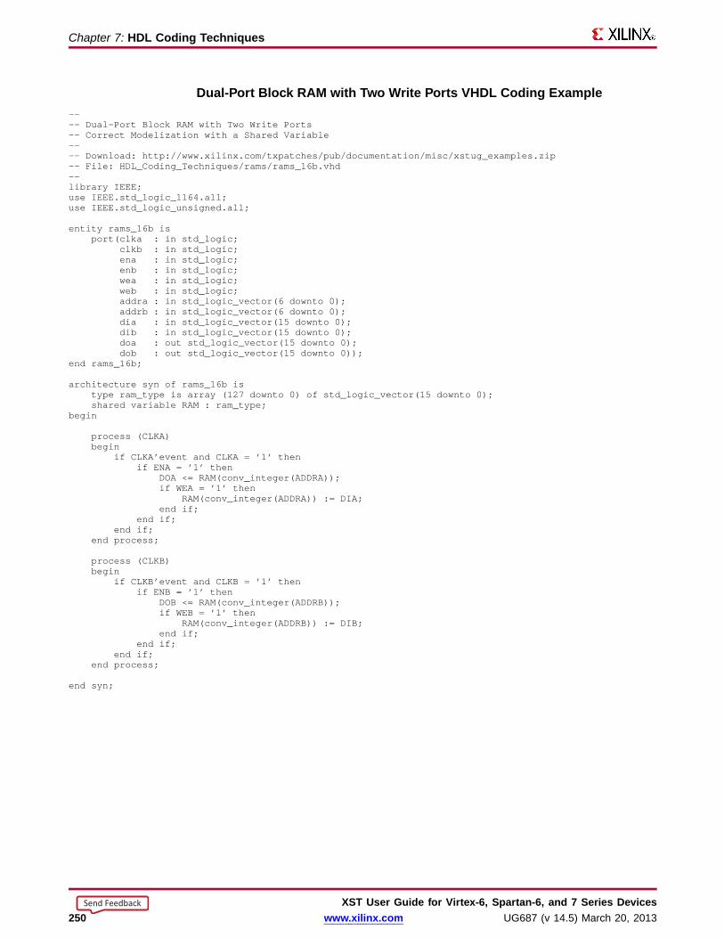
Chapter 7: HDL Coding Techniques
Dual-Por t Bloc k RAM with Two Write Por ts VHDL Coding Example---- Dual-Port Block RAMwith Two Write Ports-- Correct Modelization with a Shared Variable---- Download: http://www.xilinx.com/txpatches/pub/documentation/misc/xstug_examples.zip-- File: HDL_Coding_Techniques/rams/rams_16b.vhd--library IEEE;use IEEE.std_logic_1164.all;use IEEE.std_logic_unsigned.all;
entity rams_16b isport(clka : in std_logic;
clkb : in std_logic;ena : in std_logic;enb : in std_logic;wea : in std_logic;web : in std_logic;addra : in std_logic_vector(6 downto 0);addrb : in std_logic_vector(6 downto 0);dia : in std_logic_vector(15 downto 0);dib : in std_logic_vector(15 downto 0);doa : out std_logic_vector(15 downto 0);dob : out std_logic_vector(15 downto 0));
end rams_16b;
architecture syn of rams_16b istype ram_type is array (127 downto 0) of std_logic_vector(15 downto 0);shared variable RAM : ram_type;
begin
process (CLKA)begin
if CLKA’event and CLKA = ’1’ thenif ENA = ’1’ then
DOA <= RAM(conv_integer(ADDRA));if WEA= ’1’ then
RAM(conv_integer(ADDRA)) := DIA;end if;
end if;end if;
end process;
process (CLKB)begin
if CLKB’event and CLKB = ’1’ thenif ENB = ’1’ then
DOB <= RAM(conv_integer(ADDRB));if WEB= ’1’ then
RAM(conv_integer(ADDRB)) := DIB;end if;
end if;end if;
end process;
end syn;
XST User Guide for Vir tex-6, Spar tan-6, and 7 Series Devices250 www.xilinx.com UG687 (v 14.5) March 20, 2013
Send Feedback

Chapter 7: HDL Coding Techniques
Dual-Por t Bloc k RAM with Two Write Por ts Verilog Coding Example//// Dual-Port Block RAMwith Two Write Ports//// Download: http://www.xilinx.com/txpatches/pub/documentation/misc/xstug_examples.zip// File: HDL_Coding_Techniques/rams/rams_16.v//module v_rams_16 (clka,clkb,ena,enb,wea,web,addra,addrb,dia,dib,doa,dob);
input clka,clkb,ena,enb,wea,web;input [5:0] addra,addrb;input [15:0] dia,dib;output [15:0] doa,dob;reg [15:0] ram [63:0];reg [15:0] doa,dob;
always @(posedge clka) beginif (ena)begin
if (wea)ram[addra] <= dia;
doa <= ram[addra];end
end
always @(posedge clkb) beginif (enb)begin
if (web)ram[addrb] <= dib;
dob <= ram[addrb];end
end
endmodule
XST User Guide for Vir tex-6, Spar tan-6, and 7 Series DevicesUG687 (v 14.5) March 20, 2013 www.xilinx.com 251
Send Feedback

Chapter 7: HDL Coding Techniques
Bloc k RAM with Resettab le Data Output VHDL Coding Example---- Block RAMwith Resettable Data Output---- Download: http://www.xilinx.com/txpatches/pub/documentation/misc/xstug_examples.zip-- File: HDL_Coding_Techniques/rams/rams_18.vhd--library ieee;use ieee.std_logic_1164.all;use ieee.std_logic_unsigned.all;
entity rams_18 isport (clk : in std_logic;
en : in std_logic;we : in std_logic;rst : in std_logic;addr : in std_logic_vector(6 downto 0);di : in std_logic_vector(15 downto 0);do : out std_logic_vector(15 downto 0));
end rams_18;
architecture syn of rams_18 istype ram_type is array (127 downto 0) of std_logic_vector (15 downto 0);signal ram : ram_type;
begin
process (clk)begin
if clk’event and clk = ’1’ thenif en = ’1’ then -- optional enable
if we = ’1’ then -- write enableram(conv_integer(addr)) <= di;
end if;if rst = ’1’ then -- optional reset
do <= (others => ’0’);else
do <= ram(conv_integer(addr));end if;
end if;end if;
end process;
end syn;
XST User Guide for Vir tex-6, Spar tan-6, and 7 Series Devices252 www.xilinx.com UG687 (v 14.5) March 20, 2013
Send Feedback
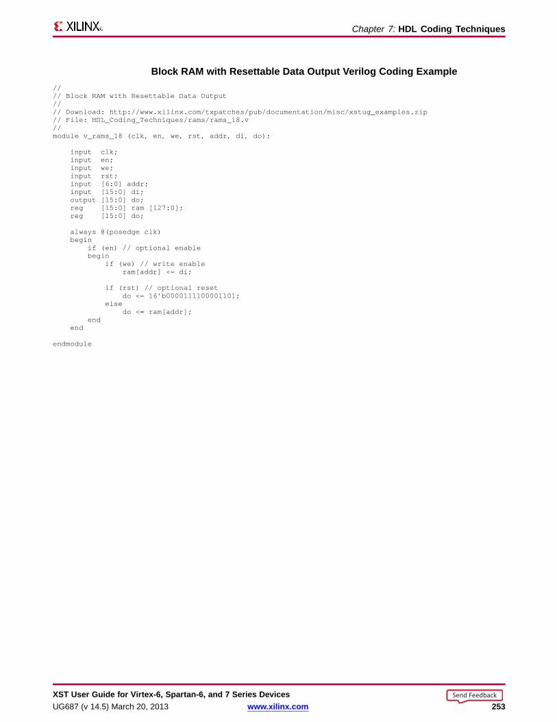
Chapter 7: HDL Coding Techniques
Bloc k RAM with Resettab le Data Output Verilog Coding Example//// Block RAMwith Resettable Data Output//// Download: http://www.xilinx.com/txpatches/pub/documentation/misc/xstug_examples.zip// File: HDL_Coding_Techniques/rams/rams_18.v//module v_rams_18 (clk, en, we, rst, addr, di, do);
input clk;input en;input we;input rst;input [6:0] addr;input [15:0] di;output [15:0] do;reg [15:0] ram [127:0];reg [15:0] do;
always @(posedge clk)begin
if (en) // optional enablebegin
if (we) // write enableram[addr] <= di;
if (rst) // optional resetdo <= 16’b0000111100001101;
elsedo <= ram[addr];
endend
endmodule
XST User Guide for Vir tex-6, Spar tan-6, and 7 Series DevicesUG687 (v 14.5) March 20, 2013 www.xilinx.com 253
Send Feedback

Chapter 7: HDL Coding Techniques
Bloc k RAM with Optional Output Register s VHDL Coding Example---- Block RAMwith Optional Output Registers---- Download: http://www.xilinx.com/txpatches/pub/documentation/misc/xstug_examples.zip-- File: HDL_Coding_Techniques/rams/rams_19.vhd--library IEEE;library IEEE;use IEEE.STD_LOGIC_1164.ALL;use IEEE.STD_LOGIC_UNSIGNED.ALL;
entity rams_19 isport (clk1, clk2 : in std_logic;
we, en1, en2 : in std_logic;addr1 : in std_logic_vector(5 downto 0);addr2 : in std_logic_vector(5 downto 0);di : in std_logic_vector(15 downto 0);res1 : out std_logic_vector(15 downto 0);res2 : out std_logic_vector(15 downto 0));
end rams_19;
architecture beh of rams_19 istype ram_type is array (63 downto 0) of std_logic_vector (15 downto 0);signal ram : ram_type;signal do1 : std_logic_vector(15 downto 0);signal do2 : std_logic_vector(15 downto 0);
begin
process (clk1)begin
if rising_edge(clk1) thenif we = ’1’ then
ram(conv_integer(addr1)) <= di;end if;do1 <= ram(conv_integer(addr1));
end if;end process;
process (clk2)begin
if rising_edge(clk2) thendo2 <= ram(conv_integer(addr2));
end if;end process;
process (clk1)begin
if rising_edge(clk1) thenif en1 = ’1’ then
res1 <= do1;end if;
end if;end process;
process (clk2)begin
if rising_edge(clk2) thenif en2 = ’1’ then
res2 <= do2;end if;
end if;end process;
end beh;
XST User Guide for Vir tex-6, Spar tan-6, and 7 Series Devices254 www.xilinx.com UG687 (v 14.5) March 20, 2013
Send Feedback

Chapter 7: HDL Coding Techniques
Bloc k RAM with Optional Output Register s Verilog Coding Example//// Block RAMwith Optional Output Registers//// Download: http://www.xilinx.com/txpatches/pub/documentation/misc/xstug_examples.zip// File: HDL_Coding_Techniques/rams/rams_19.v//module v_rams_19 (clk1, clk2, we, en1, en2, addr1, addr2, di, res1, res2);
input clk1;input clk2;input we, en1, en2;input [6:0] addr1;input [6:0] addr2;input [15:0] di;output [15:0] res1;output [15:0] res2;reg [15:0] res1;reg [15:0] res2;reg [15:0] RAM [127:0];reg [15:0] do1;reg [15:0] do2;
always @(posedge clk1)begin
if (we == 1’b1)RAM[addr1] <= di;
do1 <= RAM[addr1];end
always @(posedge clk2)begin
do2 <= RAM[addr2];end
always @(posedge clk1)begin
if (en1 == 1’b1)res1 <= do1;
end
always @(posedge clk2)begin
if (en2 == 1’b1)res2 <= do2;
end
endmodule
XST User Guide for Vir tex-6, Spar tan-6, and 7 Series DevicesUG687 (v 14.5) March 20, 2013 www.xilinx.com 255
Send Feedback

Chapter 7: HDL Coding Techniques
Initializing Bloc k RAM (Single-P or t Bloc k RAM) VHDL Coding Example---- Initializing Block RAM (Single-Port Block RAM)---- Download: http://www.xilinx.com/txpatches/pub/documentation/misc/xstug_examples.zip-- File: HDL_Coding_Techniques/rams/rams_20a.vhd--library ieee;use ieee.std_logic_1164.all;use ieee.std_logic_unsigned.all;
entity rams_20a isport (clk : in std_logic;
we : in std_logic;addr : in std_logic_vector(5 downto 0);di : in std_logic_vector(19 downto 0);do : out std_logic_vector(19 downto 0));
end rams_20a;
architecture syn of rams_20a is
type ram_type is array (63 downto 0) of std_logic_vector (19 downto 0);signal RAM : ram_type:= (X"0200A", X"00300", X"08101", X"04000", X"08601", X"0233A",
X"00300", X"08602", X"02310", X"0203B", X"08300", X"04002",X"08201", X"00500", X"04001", X"02500", X"00340", X"00241",X"04002", X"08300", X"08201", X"00500", X"08101", X"00602",X"04003", X"0241E", X"00301", X"00102", X"02122", X"02021",X"00301", X"00102", X"02222", X"04001", X"00342", X"0232B",X"00900", X"00302", X"00102", X"04002", X"00900", X"08201",X"02023", X"00303", X"02433", X"00301", X"04004", X"00301",X"00102", X"02137", X"02036", X"00301", X"00102", X"02237",X"04004", X"00304", X"04040", X"02500", X"02500", X"02500",X"0030D", X"02341", X"08201", X"0400D");
begin
process (clk)begin
if rising_edge(clk) thenif we = ’1’ then
RAM(conv_integer(addr)) <= di;end if;
do <= RAM(conv_integer(addr));end if;
end process;
end syn;
XST User Guide for Vir tex-6, Spar tan-6, and 7 Series Devices256 www.xilinx.com UG687 (v 14.5) March 20, 2013
Send Feedback
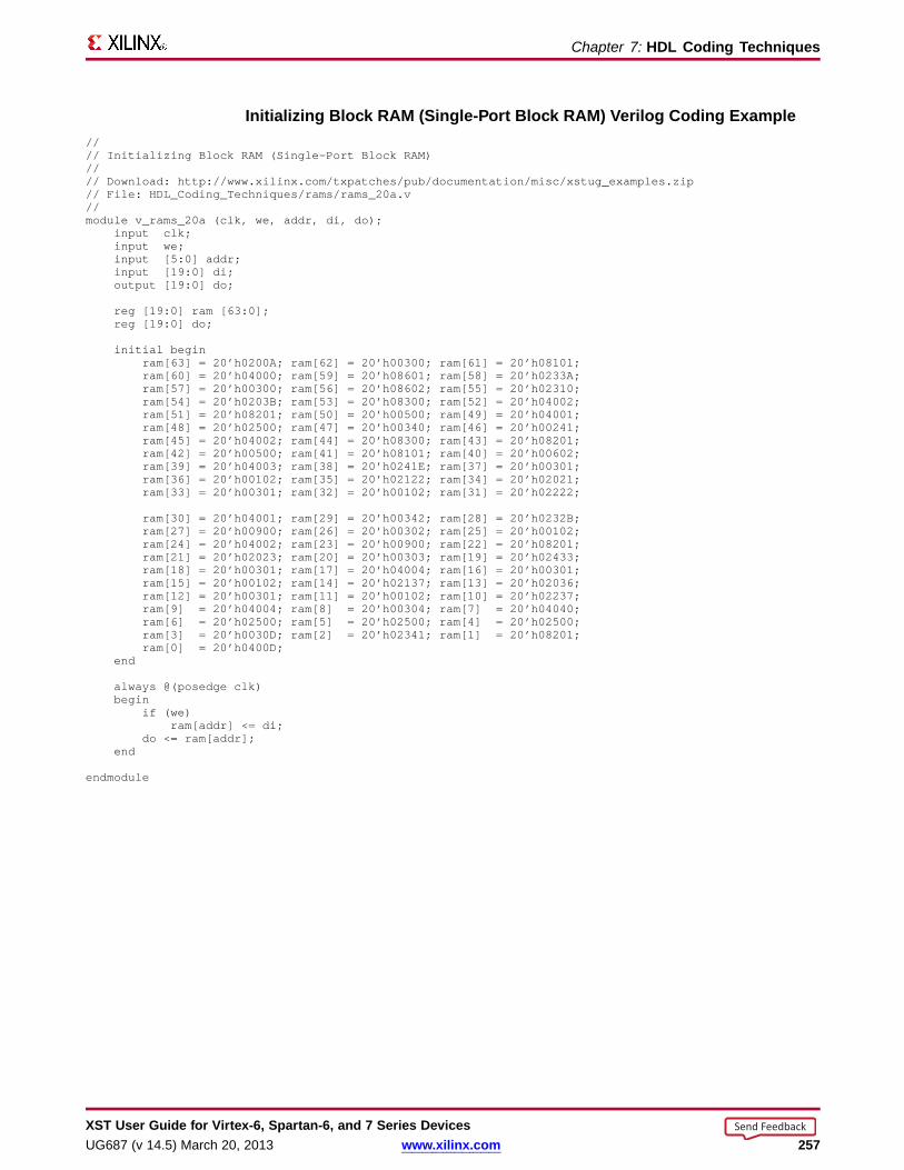
Chapter 7: HDL Coding Techniques
Initializing Bloc k RAM (Single-P or t Bloc k RAM) Verilog Coding Example//// Initializing Block RAM (Single-Port Block RAM)//// Download: http://www.xilinx.com/txpatches/pub/documentation/misc/xstug_examples.zip// File: HDL_Coding_Techniques/rams/rams_20a.v//module v_rams_20a (clk, we, addr, di, do);
input clk;input we;input [5:0] addr;input [19:0] di;output [19:0] do;
reg [19:0] ram [63:0];reg [19:0] do;
initial beginram[63] = 20’h0200A; ram[62] = 20’h00300; ram[61] = 20’h08101;ram[60] = 20’h04000; ram[59] = 20’h08601; ram[58] = 20’h0233A;ram[57] = 20’h00300; ram[56] = 20’h08602; ram[55] = 20’h02310;ram[54] = 20’h0203B; ram[53] = 20’h08300; ram[52] = 20’h04002;ram[51] = 20’h08201; ram[50] = 20’h00500; ram[49] = 20’h04001;ram[48] = 20’h02500; ram[47] = 20’h00340; ram[46] = 20’h00241;ram[45] = 20’h04002; ram[44] = 20’h08300; ram[43] = 20’h08201;ram[42] = 20’h00500; ram[41] = 20’h08101; ram[40] = 20’h00602;ram[39] = 20’h04003; ram[38] = 20’h0241E; ram[37] = 20’h00301;ram[36] = 20’h00102; ram[35] = 20’h02122; ram[34] = 20’h02021;ram[33] = 20’h00301; ram[32] = 20’h00102; ram[31] = 20’h02222;
ram[30] = 20’h04001; ram[29] = 20’h00342; ram[28] = 20’h0232B;ram[27] = 20’h00900; ram[26] = 20’h00302; ram[25] = 20’h00102;ram[24] = 20’h04002; ram[23] = 20’h00900; ram[22] = 20’h08201;ram[21] = 20’h02023; ram[20] = 20’h00303; ram[19] = 20’h02433;ram[18] = 20’h00301; ram[17] = 20’h04004; ram[16] = 20’h00301;ram[15] = 20’h00102; ram[14] = 20’h02137; ram[13] = 20’h02036;ram[12] = 20’h00301; ram[11] = 20’h00102; ram[10] = 20’h02237;ram[9] = 20’h04004; ram[8] = 20’h00304; ram[7] = 20’h04040;ram[6] = 20’h02500; ram[5] = 20’h02500; ram[4] = 20’h02500;ram[3] = 20’h0030D; ram[2] = 20’h02341; ram[1] = 20’h08201;ram[0] = 20’h0400D;
end
always @(posedge clk)begin
if (we)ram[addr] <= di;
do <= ram[addr];end
endmodule
XST User Guide for Vir tex-6, Spar tan-6, and 7 Series DevicesUG687 (v 14.5) March 20, 2013 www.xilinx.com 257
Send Feedback
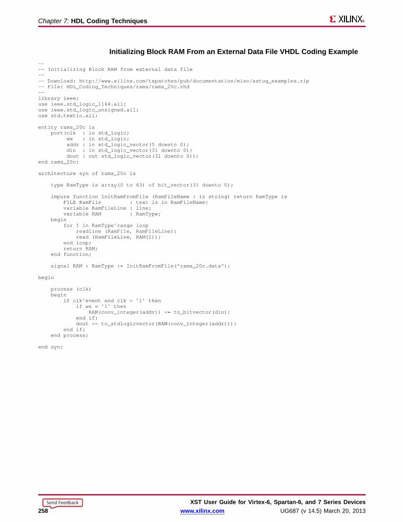
Chapter 7: HDL Coding Techniques
Initializing Bloc k RAM From an External Data File VHDL Coding Example---- Initializing Block RAM from external data file---- Download: http://www.xilinx.com/txpatches/pub/documentation/misc/xstug_examples.zip-- File: HDL_Coding_Techniques/rams/rams_20c.vhd--library ieee;use ieee.std_logic_1164.all;use ieee.std_logic_unsigned.all;use std.textio.all;
entity rams_20c isport(clk : in std_logic;
we : in std_logic;addr : in std_logic_vector(5 downto 0);din : in std_logic_vector(31 downto 0);dout : out std_logic_vector(31 downto 0));
end rams_20c;
architecture syn of rams_20c is
type RamType is array(0 to 63) of bit_vector(31 downto 0);
impure function InitRamFromFile (RamFileName : in string) return RamType isFILE RamFile : text is in RamFileName;variable RamFileLine : line;variable RAM : RamType;
beginfor I in RamType’range loop
readline (RamFile, RamFileLine);read (RamFileLine, RAM(I));
end loop;return RAM;
end function;
signal RAM : RamType := InitRamFromFile("rams_20c.data");
begin
process (clk)begin
if clk’event and clk = ’1’ thenif we = ’1’ then
RAM(conv_integer(addr)) <= to_bitvector(din);end if;dout <= to_stdlogicvector(RAM(conv_integer(addr)));
end if;end process;
end syn;
XST User Guide for Vir tex-6, Spar tan-6, and 7 Series Devices258 www.xilinx.com UG687 (v 14.5) March 20, 2013
Send Feedback
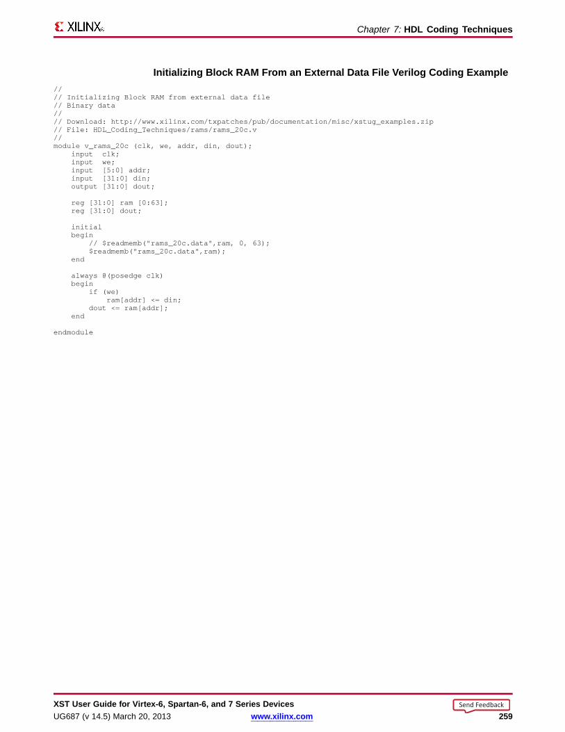
Chapter 7: HDL Coding Techniques
Initializing Bloc k RAM From an External Data File Verilog Coding Example//// Initializing Block RAM from external data file// Binary data//// Download: http://www.xilinx.com/txpatches/pub/documentation/misc/xstug_examples.zip// File: HDL_Coding_Techniques/rams/rams_20c.v//module v_rams_20c (clk, we, addr, din, dout);
input clk;input we;input [5:0] addr;input [31:0] din;output [31:0] dout;
reg [31:0] ram [0:63];reg [31:0] dout;
initialbegin
// $readmemb("rams_20c.data",ram, 0, 63);$readmemb("rams_20c.data",ram);
end
always @(posedge clk)begin
if (we)ram[addr] <= din;
dout <= ram[addr];end
endmodule
XST User Guide for Vir tex-6, Spar tan-6, and 7 Series DevicesUG687 (v 14.5) March 20, 2013 www.xilinx.com 259
Send Feedback

Chapter 7: HDL Coding Techniques
Pipelined Distrib uted RAM VHDL Coding Example---- Pipeline distributed RAM---- Download: http://www.xilinx.com/txpatches/pub/documentation/misc/xstug_examples.zip-- File: HDL_Coding_Techniques/rams/rams_22.vhd--library ieee;use ieee.std_logic_1164.all;use ieee.std_logic_unsigned.all;
entity rams_22 isport (clk : in std_logic;
we : in std_logic;addr : in std_logic_vector(8 downto 0);di : in std_logic_vector(3 downto 0);do : out std_logic_vector(3 downto 0));
end rams_22;
architecture syn of rams_22 istype ram_type is array (511 downto 0) of std_logic_vector (3 downto 0);signal RAM : ram_type;
signal pipe_reg: std_logic_vector(3 downto 0);
attribute ram_style: string;attribute ram_style of RAM: signal is "pipe_distributed";
begin
process (clk)begin
if clk’event and clk = ’1’ thenif we = ’1’ then
RAM(conv_integer(addr)) <= di;else
pipe_reg <= RAM( conv_integer(addr));end if;do <= pipe_reg;
end if;end process;
end syn;
XST User Guide for Vir tex-6, Spar tan-6, and 7 Series Devices260 www.xilinx.com UG687 (v 14.5) March 20, 2013
Send Feedback

Chapter 7: HDL Coding Techniques
Pipelined Distrib uted RAM Verilog Coding Example//// Pipeline distributed RAM//// Download: http://www.xilinx.com/txpatches/pub/documentation/misc/xstug_examples.zip// File: HDL_Coding_Techniques/rams/rams_22.v//module v_rams_22 (clk, we, addr, di, do);
input clk;input we;input [8:0] addr;input [3:0] di;output [3:0] do;
(*ram_style="pipe_distributed"*)reg [3:0] RAM [511:0];reg [3:0] do;reg [3:0] pipe_reg;
always @(posedge clk)begin
if (we)RAM[addr] <= di;
elsepipe_reg <= RAM[addr];
do <= pipe_reg;end
endmodule
XST User Guide for Vir tex-6, Spar tan-6, and 7 Series DevicesUG687 (v 14.5) March 20, 2013 www.xilinx.com 261
Send Feedback
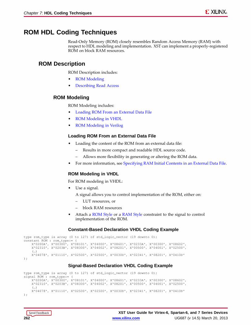
Chapter 7: HDL Coding Techniques
ROM HDL Coding TechniquesRead-Only Memory (ROM) closely resembles Random Access Memory (RAM) withrespect to HDLmodeling and implementation. XST can implement a properly-registeredROM on block RAM resources.
ROM DescriptionROM Description includes:• ROM Modeling• Describing Read Access
ROM ModelingROM Modeling includes:• Loading ROM From an External Data File• ROM Modeling in VHDL• ROM Modeling in Verilog
Loading ROM From an External Data File• Loading the content of the ROM from an external data file:
– Results in more compact and readable HDL source code.– Allows more flexibility in generating or altering the ROM data.
• For more information, see Specifying RAM Initial Contents in an External Data File.
ROM Modeling in VHDLFor ROM modeling in VHDL:• Use a signal.
A signal allows you to control implementation of the ROM, either on:– LUT resources, or– block RAM resources
• Attach a ROM Style or a RAM Style constraint to the signal to controlimplementation of the ROM.
Constant-Based Declaration VHDL Coding Exampletype rom_type is array (0 to 127) of std_logic_vector (19 downto 0);constant ROM: rom_type:= (
X"0200A", X"00300", X"08101", X"04000", X"08601", X"0233A", X"00300", X"08602",X"02310", X"0203B", X"08300", X"04002", X"08201", X"00500", X"04001", X"02500",(…)X"04078", X"01110", X"02500", X"02500", X"0030D", X"02341", X"08201", X"0410D"
);
Signal-Based Declaration VHDL Coding Exampletype rom_type is array (0 to 127) of std_logic_vector (19 downto 0);signal ROM: rom_type:= (
X"0200A", X"00300", X"08101", X"04000", X"08601", X"0233A", X"00300", X"08602",X"02310", X"0203B", X"08300", X"04002", X"08201", X"00500", X"04001", X"02500",(…)X"04078", X"01110", X"02500", X"02500", X"0030D", X"02341", X"08201", X"0410D"
);
XST User Guide for Vir tex-6, Spar tan-6, and 7 Series Devices262 www.xilinx.com UG687 (v 14.5) March 20, 2013
Send Feedback
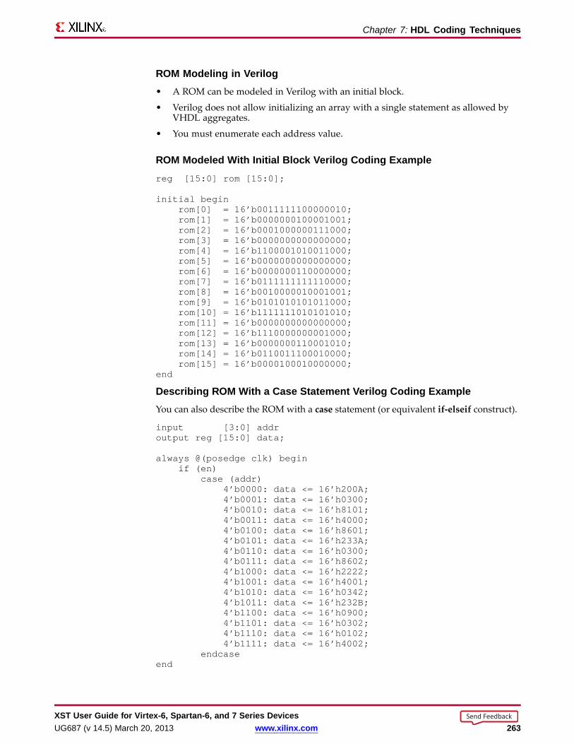
Chapter 7: HDL Coding Techniques
ROM Modeling in Verilog• A ROM can be modeled in Verilog with an initial block.
• Verilog does not allow initializing an array with a single statement as allowed byVHDL aggregates.
• You must enumerate each address value.
ROM Modeled With Initial Bloc k Verilog Coding Examplereg [15:0] rom [15:0];
initial beginrom[0] = 16’b0011111100000010;rom[1] = 16’b0000000100001001;rom[2] = 16’b0001000000111000;rom[3] = 16’b0000000000000000;rom[4] = 16’b1100001010011000;rom[5] = 16’b0000000000000000;rom[6] = 16’b0000000110000000;rom[7] = 16’b0111111111110000;rom[8] = 16’b0010000010001001;rom[9] = 16’b0101010101011000;rom[10] = 16’b1111111010101010;rom[11] = 16’b0000000000000000;rom[12] = 16’b1110000000001000;rom[13] = 16’b0000000110001010;rom[14] = 16’b0110011100010000;rom[15] = 16’b0000100010000000;
end
Describing ROM With a Case Statement Verilog Coding ExampleYou can also describe the ROM with a case statement (or equivalent if-elseif construct).
input [3:0] addroutput reg [15:0] data;
always @(posedge clk) beginif (en)
case (addr)4’b0000: data <= 16’h200A;4’b0001: data <= 16’h0300;4’b0010: data <= 16’h8101;4’b0011: data <= 16’h4000;4’b0100: data <= 16’h8601;4’b0101: data <= 16’h233A;4’b0110: data <= 16’h0300;4’b0111: data <= 16’h8602;4’b1000: data <= 16’h2222;4’b1001: data <= 16’h4001;4’b1010: data <= 16’h0342;4’b1011: data <= 16’h232B;4’b1100: data <= 16’h0900;4’b1101: data <= 16’h0302;4’b1110: data <= 16’h0102;4’b1111: data <= 16’h4002;
endcaseend
XST User Guide for Vir tex-6, Spar tan-6, and 7 Series DevicesUG687 (v 14.5) March 20, 2013 www.xilinx.com 263
Send Feedback
Chapter 7: HDL Coding Techniques
Describing Read AccessDescribing access to ROM is similar to describing access to RAM.
Describing Read Access VHDL Coding ExampleIf you have included the IEEE std_logic_unsigned package defining the conv_integerconversion function, the VHDL syntax is:
signal addr : std_logic_vector(ADDR_WIDTH-1 downto 0);do <= ROM( conv_integer(addr));
Describing Read Access Verilog Coding Example• If you have modeled the ROM in an initial block (with data described in the Verilog
source code or loaded from an external data file), the Verilog syntax is:
do <= ROM[addr];
• You can also use a case construct as shown in Describing ROM With a CaseStatement Verilog Coding Example.
ROM Implementation• When XST detects that a properly synchronized ROM can be implemented on block
RAM resources, it applies the principles outlined in Block RAM OptimizationStrategies.
• To override any default XST decision criteria, use ROM Style instead of RAM Style.
• For more information about ROM Style, see Chapter 9, Design Constraints.
• For more information about ROM implementation, see Chapter 8, FPGAOptimization.
ROM Related ConstraintsROM Style
ROM Repor tingThe following report shows how the Read-Only Memory (ROM) is identified duringHDL Synthesis. Based on the availability of proper synchronization, the decision toimplement a ROM on block RAM resources is made during Advanced HDL Synthesis.
XST User Guide for Vir tex-6, Spar tan-6, and 7 Series Devices264 www.xilinx.com UG687 (v 14.5) March 20, 2013
Send Feedback

Chapter 7: HDL Coding Techniques
ROM Repor ting Example=========================================================================* HDL Synthesis *=========================================================================
Synthesizing Unit <roms_signal>.Found 20-bit register for signal <data>.Found 128x20-bit ROMfor signal <n0024>.Summary:
inferred 1 ROM(s).inferred 20 D-type flip-flop(s).Unit <roms_signal> synthesized.
=========================================================================HDL Synthesis Report
Macro Statistics# ROMs : 1128x20-bit ROM : 1# Registers : 120-bit register : 1
=========================================================================
=========================================================================* Advanced HDL Synthesis *=========================================================================
Synthesizing (advanced) Unit <roms_signal>.INFO:Xst - The ROM<Mrom_ROM>will be implemented as a read-only BLOCKRAM,absorbing the register: <data>.INFO:Xst - The RAM<Mrom_ROM>will be implemented as BLOCKRAM
-----------------------------------------------------------------------| ram_type | Block | |-----------------------------------------------------------------------| Port A || aspect ratio | 128-word x 20-bit | || mode | write-first | || clkA | connected to signal <clk> | rise || enA | connected to signal <en> | high || weA | connected to internal node | high || addrA | connected to signal <addr> | || diA | connected to internal node | || doA | connected to signal <data> | |-----------------------------------------------------------------------| optimization | speed | |-----------------------------------------------------------------------
Unit <roms_signal> synthesized (advanced).
=========================================================================Advanced HDL Synthesis Report
Macro Statistics# RAMs : 1128x20-bit single-port block RAM : 1
=========================================================================
ROM Coding ExamplesFor update information, see “Coding Examples” in the Introduction.
XST User Guide for Vir tex-6, Spar tan-6, and 7 Series DevicesUG687 (v 14.5) March 20, 2013 www.xilinx.com 265
Send Feedback

Chapter 7: HDL Coding Techniques
Description of a ROM with a VHDL Constant Coding Example---- Description of a ROMwith a VHDL constant---- Download: http://www.xilinx.com/txpatches/pub/documentation/misc/xstug_examples.zip-- File: HDL_Coding_Techniques/rams/roms_constant.vhd--library ieee;use ieee.std_logic_1164.all;use ieee.std_logic_unsigned.all;
entity roms_constant isport (clk : in std_logic;
en : in std_logic;addr : in std_logic_vector(6 downto 0);data : out std_logic_vector(19 downto 0));
end roms_constant;
architecture syn of roms_constant is
type rom_type is array (0 to 127) of std_logic_vector (19 downto 0);constant ROM: rom_type:= (
X"0200A", X"00300", X"08101", X"04000", X"08601", X"0233A", X"00300", X"08602",X"02310", X"0203B", X"08300", X"04002", X"08201", X"00500", X"04001", X"02500",X"00340", X"00241", X"04002", X"08300", X"08201", X"00500", X"08101", X"00602",
X"04003", X"0241E", X"00301", X"00102", X"02122", X"02021", X"00301", X"00102",X"02222", X"04001", X"00342", X"0232B", X"00900", X"00302", X"00102", X"04002",X"00900", X"08201", X"02023", X"00303", X"02433", X"00301", X"04004", X"00301",
X"00102", X"02137", X"02036", X"00301", X"00102", X"02237", X"04004", X"00304",X"04040", X"02500", X"02500", X"02500", X"0030D", X"02341", X"08201", X"0400D",
X"0200A", X"00300", X"08101", X"04000", X"08601", X"0233A", X"00300", X"08602",X"02310", X"0203B", X"08300", X"04002", X"08201", X"00500", X"04001", X"02500",X"00340", X"00241", X"04112", X"08300", X"08201", X"00500", X"08101", X"00602",
X"04003", X"0241E", X"00301", X"00102", X"02122", X"02021", X"00301", X"00102",X"02222", X"04001", X"00342", X"0232B", X"00870", X"00302", X"00102", X"04002",X"00900", X"08201", X"02023", X"00303", X"02433", X"00301", X"04004", X"00301",
X"00102", X"02137", X"FF036", X"00301", X"00102", X"10237", X"04934", X"00304",X"04078", X"01110", X"02500", X"02500", X"0030D", X"02341", X"08201", X"0410D");
begin
process (clk)begin
if (clk’event and clk = ’1’) thenif (en = ’1’) then
data <= ROM(conv_integer(addr));end if;
end if;end process;
end syn;
XST User Guide for Vir tex-6, Spar tan-6, and 7 Series Devices266 www.xilinx.com UG687 (v 14.5) March 20, 2013
Send Feedback
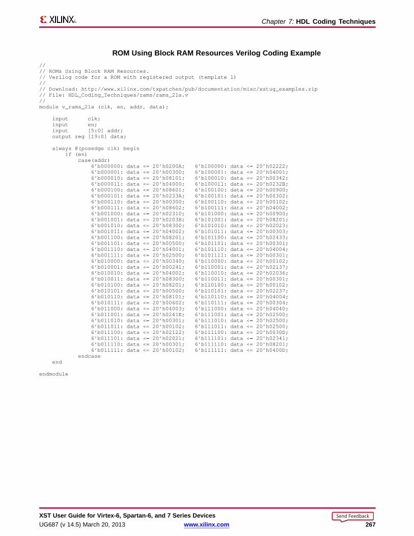
Chapter 7: HDL Coding Techniques
ROM Using Bloc k RAM Resour ces Verilog Coding Example//// ROMsUsing Block RAMResources.// Verilog code for a ROMwith registered output (template 1)//// Download: http://www.xilinx.com/txpatches/pub/documentation/misc/xstug_examples.zip// File: HDL_Coding_Techniques/rams/rams_21a.v//module v_rams_21a (clk, en, addr, data);
input clk;input en;input [5:0] addr;output reg [19:0] data;
always @(posedge clk) beginif (en)
case(addr)6’b000000: data <= 20’h0200A; 6’b100000: data <= 20’h02222;6’b000001: data <= 20’h00300; 6’b100001: data <= 20’h04001;6’b000010: data <= 20’h08101; 6’b100010: data <= 20’h00342;6’b000011: data <= 20’h04000; 6’b100011: data <= 20’h0232B;6’b000100: data <= 20’h08601; 6’b100100: data <= 20’h00900;6’b000101: data <= 20’h0233A; 6’b100101: data <= 20’h00302;6’b000110: data <= 20’h00300; 6’b100110: data <= 20’h00102;6’b000111: data <= 20’h08602; 6’b100111: data <= 20’h04002;6’b001000: data <= 20’h02310; 6’b101000: data <= 20’h00900;6’b001001: data <= 20’h0203B; 6’b101001: data <= 20’h08201;6’b001010: data <= 20’h08300; 6’b101010: data <= 20’h02023;6’b001011: data <= 20’h04002; 6’b101011: data <= 20’h00303;6’b001100: data <= 20’h08201; 6’b101100: data <= 20’h02433;6’b001101: data <= 20’h00500; 6’b101101: data <= 20’h00301;6’b001110: data <= 20’h04001; 6’b101110: data <= 20’h04004;6’b001111: data <= 20’h02500; 6’b101111: data <= 20’h00301;6’b010000: data <= 20’h00340; 6’b110000: data <= 20’h00102;6’b010001: data <= 20’h00241; 6’b110001: data <= 20’h02137;6’b010010: data <= 20’h04002; 6’b110010: data <= 20’h02036;6’b010011: data <= 20’h08300; 6’b110011: data <= 20’h00301;6’b010100: data <= 20’h08201; 6’b110100: data <= 20’h00102;6’b010101: data <= 20’h00500; 6’b110101: data <= 20’h02237;6’b010110: data <= 20’h08101; 6’b110110: data <= 20’h04004;6’b010111: data <= 20’h00602; 6’b110111: data <= 20’h00304;6’b011000: data <= 20’h04003; 6’b111000: data <= 20’h04040;6’b011001: data <= 20’h0241E; 6’b111001: data <= 20’h02500;6’b011010: data <= 20’h00301; 6’b111010: data <= 20’h02500;6’b011011: data <= 20’h00102; 6’b111011: data <= 20’h02500;6’b011100: data <= 20’h02122; 6’b111100: data <= 20’h0030D;6’b011101: data <= 20’h02021; 6’b111101: data <= 20’h02341;6’b011110: data <= 20’h00301; 6’b111110: data <= 20’h08201;6’b011111: data <= 20’h00102; 6’b111111: data <= 20’h0400D;
endcaseend
endmodule
XST User Guide for Vir tex-6, Spar tan-6, and 7 Series DevicesUG687 (v 14.5) March 20, 2013 www.xilinx.com 267
Send Feedback
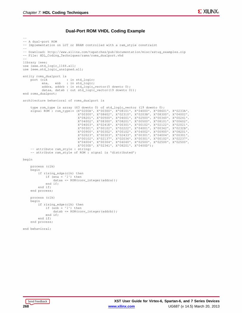
Chapter 7: HDL Coding Techniques
Dual-Por t ROM VHDL Coding Example---- A dual-port ROM-- Implementation on LUT or BRAMcontrolled with a ram_style constraint---- Download: http://www.xilinx.com/txpatches/pub/documentation/misc/xstug_examples.zip-- File: HDL_Coding_Techniques/rams/roms_dualport.vhd--library ieee;use ieee.std_logic_1164.all;use ieee.std_logic_unsigned.all;
entity roms_dualport isport (clk : in std_logic;
ena, enb : in std_logic;addra, addrb : in std_logic_vector(5 downto 0);dataa, datab : out std_logic_vector(19 downto 0));
end roms_dualport;
architecture behavioral of roms_dualport is
type rom_type is array (63 downto 0) of std_logic_vector (19 downto 0);signal ROM: rom_type:= (X"0200A", X"00300", X"08101", X"04000", X"08601", X"0233A",
X"00300", X"08602", X"02310", X"0203B", X"08300", X"04002",X"08201", X"00500", X"04001", X"02500", X"00340", X"00241",X"04002", X"08300", X"08201", X"00500", X"08101", X"00602",X"04003", X"0241E", X"00301", X"00102", X"02122", X"02021",X"00301", X"00102", X"02222", X"04001", X"00342", X"0232B",X"00900", X"00302", X"00102", X"04002", X"00900", X"08201",X"02023", X"00303", X"02433", X"00301", X"04004", X"00301",X"00102", X"02137", X"02036", X"00301", X"00102", X"02237",X"04004", X"00304", X"04040", X"02500", X"02500", X"02500",X"0030D", X"02341", X"08201", X"0400D");
-- attribute ram_style : string;-- attribute ram_style of ROM: signal is "distributed";
begin
process (clk)begin
if rising_edge(clk) thenif (ena = ’1’) then
dataa <= ROM(conv_integer(addra));end if;
end if;end process;
process (clk)begin
if rising_edge(clk) thenif (enb = ’1’) then
datab <= ROM(conv_integer(addrb));end if;
end if;end process;
end behavioral;
XST User Guide for Vir tex-6, Spar tan-6, and 7 Series Devices268 www.xilinx.com UG687 (v 14.5) March 20, 2013
Send Feedback

Chapter 7: HDL Coding Techniques
FSM Components• XST features:
– Specific inference capabilities for synchronous Finite State Machine (FSM)components.
– Built-in FSM encoding strategies to accommodate your optimization goals.
• You may also instruct XST to follow your own encoding scheme.
• FSM extraction is enabled by default.
• Use Automatic FSM Extraction to disable FSM extraction.
FSM Description• XST supports specification of Finite State Machine (FSM) in both Moore and Mealy
form.
• An FSM consists of:
– State register
– Next state function
– Outputs function
HDL Coding Methods• You can choose among many HDL coding methods. Your choice depends on your
goals with respect to code compactness and readability.
• The following HDL coding methods:
– Ensure maximum readability.
– Maximize the ability of XST to identify the FSM.
• Method One
Describe all three components of the FSM in a single sequential process or alwaysblock.
• Method Two
1. Describe the state register and next state function together in a sequentialprocess or always block.
2. Describe the outputs function in a separate combinatorial process or alwaysblock.
• Method Three
1. Describe the state register in a sequential process or always block.
2. Describe the next state and outputs functions together in a separatecombinatorial process or always block.
• Method Four
1. Describe the state register in a sequential process or always block.
2. Describe the next state function in a first combinatorial process or always block.
3. Describe the outputs function in a second separate combinatorial process oralways block.
XST User Guide for Vir tex-6, Spar tan-6, and 7 Series DevicesUG687 (v 14.5) March 20, 2013 www.xilinx.com 269
Send Feedback

Chapter 7: HDL Coding Techniques
FSM Representation Incorporating Mealy and Moore MachinesDiagram
FSM With Three Processes Diagram
State Register s• Specify a reset or power-up state for XST to identify a Finite State Machine (FSM).
• The State Register can be asynchronously or synchronously reset to a particular state.
• Xilinx® recommends using synchronous reset logic over asynchronous reset logicfor an FSM.
Specifying State Register s in VHDLYou can specify a State Register in VHDL with:
• Standard Type
• Enumerated Type
Standar d Type
Specify the State Register with a Standard Type such as:
• integer
• bit_vector
• std_logic_vector
Enumerated Type
1. Define an Enumerated Type containing all possible state values.
2. Declare the state register with that type.
type state_type is (state1, state2, state3, state4);signal state : state_type;
XST User Guide for Vir tex-6, Spar tan-6, and 7 Series Devices270 www.xilinx.com UG687 (v 14.5) March 20, 2013
Send Feedback

Chapter 7: HDL Coding Techniques
Specifying State Register s in Verilog• A State Register type in Verilog is:
– An integer, or– A set of defined parameters.
parameter [3:0]s1 = 4’b0001,s2 = 4’b0010,s3 = 4’b0100,s4 = 4’b1000;
reg [3:0] state;
• Modify these parameters to represent different state encoding schemes.
Next State Equation• Next state equations can be described:
– Directly in the sequential process, or– In a separate combinatorial process
• The sensitivity list of a separate combinatorial process contains:– The state signal– All Finite State Machine (FSM) inputs
• The simplest coding example is based on a case statement, the selector of which isthe current state signal.
Unreachable StatesXST detects and reports unreachable states.
FSM Outputs• Non-registered outputs are described in:
– The combinatorial process, or– Concurrent assignments
• Registered outputs must be assigned in the sequential process.
FSM Inputs• Registered inputs are described using internal signals.• Internal signals are assigned in the sequential process.
State Encoding Techniques• XST state encoding techniques accommodate different optimization goals, and
different Finite State Machine (FSM) patterns.• Use FSM Encoding Algorithm to select the state encoding technique.• For more information, see Chapter 9, Design Constraints.
Auto State EncodingXST tries to select the best suited encoding method for a given FSM.
XST User Guide for Vir tex-6, Spar tan-6, and 7 Series DevicesUG687 (v 14.5) March 20, 2013 www.xilinx.com 271
Send Feedback
Chapter 7: HDL Coding Techniques
One-Hot State Encoding• Is the default encoding scheme.
• Is usually a good choice for optimizing speed or reducing power dissipation.
• Assigns a distinct bit of code to each FSM state.
• Implements the State Register with one flip-flop for each state.
– In a given clock cycle during operation, one and only one bit of the StateRegister is asserted.
– Only two bits toggle during a transition between two states.
Gray State Encoding• Guarantees that only one bit switches between two consecutive states.
• Is appropriate for controllers exhibiting long paths without branching.
• Minimizes hazards and glitches.
• Gives good results when implementing the State Register with T Flip-Flops.
• Can be used to minimize power dissipation.
Compact State Encoding• Minimizes the number of bits in the state variables and flip-flops. This technique is
based on hypercube immersion.
• Is appropriate when trying to optimize area.
Johnson State EncodingBeneficial when using state machines containing long paths with no branching (as inGray State Encoding).
Sequential State Encoding• Identifies long paths
• Applies successive radix two codes to the states on these paths.
• Minimizes next state equations.
Speed1 State Encoding• Is oriented for speed optimization.
• The number of bits for a State Register depends on the specific FSM, but is generallygreater than the number of FSM states.
User State EncodingXST uses the original encoding specified in the HDL file.
User State Encoding ExampleIf the State Register is described based on an enumerated type:
• Use Enumerated Encoding to assign a specific binary value to each state.
• Select User State Encoding to instruct XST to follow your coding scheme.
XST User Guide for Vir tex-6, Spar tan-6, and 7 Series Devices272 www.xilinx.com UG687 (v 14.5) March 20, 2013
Send Feedback

Chapter 7: HDL Coding Techniques
Implementing FSM Components on Bloc k RAM Resour ces• Finite State Machine (FSM) components are implemented on slice logic.
– To save slice logic resources, instruct XST to implement FSM components inblock RAM.
– Implementing FSM components in block RAM can enhance the performance oflarge FSM components.
• To select the implementation for slice logic, use FSM Style to choose between:
– default implementation
– block RAM implementation
• The values for FSM Style are:
– lut (default)
– bram
• If XST cannot implement an FSM in block RAM:
– XST implements the state machine in slice logic.
– XST issues a warning during Advanced HDL Synthesis.
• The failure to implement an FSM in block RAM usually occurs when the FSM hasan asynchronous reset.
FSM Safe ImplementationSafe Finite State Machine (FSM) design is a subject of debate. There is no single perfectsolution. Xilinx® recommends that you carefully review the following sections beforedeciding on your implementation strategy.
Optimization• Optimization is standard for the great majority of applications. Most applications
operate in normal external conditions. Their temporary failure due to a single eventupset does not have critical consequences.
• XST detects and optimizes the following by default:
– Unreachable states (both logical and physical)
– Related transition logic
• Optimization ensures implementation of a state machine that:
– Uses minimal device resources.
– Provides optimal circuit performance.
XST User Guide for Vir tex-6, Spar tan-6, and 7 Series DevicesUG687 (v 14.5) March 20, 2013 www.xilinx.com 273
Send Feedback
Chapter 7: HDL Coding Techniques
Preventing Optimization• Some applications operate in external conditions in which the potentially
catastrophic impact of soft errors cannot be ignored. Optimization is not appropriatefor these applications.
• These soft errors are caused primarily by:– Cosmic rays, or– Alpha particles from the chip packaging
• State machines are sensible to soft errors. A state machine may never resumenormal operation after an external condition sends it to an illegal state. For thecircuit to be able to detect and recover from those errors, unreachable states mustnot be optimized away.
• Use Safe Implementation to prevent optimization. XST creates additional logicallowing the state machine to:– Detect an illegal transition.– Return to a valid recovery state.
• XST selects the reset state as the recovery state by default. If no reset state isavailable, XST selects the power-up state. Use Safe Recovery State to manuallydefine a specific recovery state.
One-Hot Encoding Versus Binar y Encoding• With binary State Encoding Techniques (such as Compact, Sequential, and Gray),
the state register is implemented with a minimum number of Flip-Flops. One-HotEncoding implies a larger number of Flip-Flops (one for each valid state). Thisincreases the likelihood of a single event upset affecting the State Register.
• Despite this drawback, One-Hot Encoding has a significant topological benefit.A Hamming distance of 2 makes all single bit errors easily detectable. An illegaltransition resulting from a single bit error always sends the state machine to aninvalid state. The XST safe implementation logic ensures that any such error isdetected and cleanly recovered from.
• An equivalent binary coded state machine has a Hamming distance of 1. As a result,a single bit error may send the state machine to an unexpected but valid state. If thenumber of valid states is a power of 2, all possible code values correspond to a validstate, and a soft error always produces such an outcome. In that event, the circuitdoes not detect that an illegal transition has occurred, and that the state machine hasnot executed its normal state sequence. Such a random and uncontrolled recoverymay not be acceptable.
Recovery-Onl y States• Xilinx recommends that you define a recovery state that is none of the normal
operating states of your state machine.• Defining a recovery-only state allows you to:
– Detect that the state machine has been affected by a single event upset.– Perform specific actions before resuming normal operation. Such actions include
flagging the recovery condition to the rest of the circuit or to a circuit output.• Directly recovering to a normal operation state is sufficient, provided that the faulty
state machine does not need to:– Inform the rest of the circuit of its temporary condition, or– Perform specific actions following a soft error.
XST User Guide for Vir tex-6, Spar tan-6, and 7 Series Devices274 www.xilinx.com UG687 (v 14.5) March 20, 2013
Send Feedback
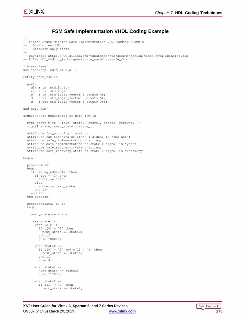
Chapter 7: HDL Coding Techniques
FSM Safe Implementation VHDL Coding Example---- Finite State Machine Safe Implementation VHDL Coding Example-- One-hot encoding-- Recovery-only state---- Download: http://www.xilinx.com/txpatches/pub/documentation/misc/xstug_examples.zip-- File: HDL_Coding_Techniques/state_machines/safe_fsm.vhd--library ieee;use ieee.std_logic_1164.all;
entity safe_fsm is
port(clk : in std_logic;rst : in std_logic;c : in std_logic_vector(3 downto 0);d : in std_logic_vector(3 downto 0);q : out std_logic_vector(3 downto 0));
end safe_fsm;
architecture behavioral of safe_fsm is
type state_t is ( idle, state0, state1, state2, recovery );signal state, next_state : state_t;
attribute fsm_encoding : string;attribute fsm_encoding of state : signal is "one-hot";attribute safe_implementation : string;attribute safe_implementation of state : signal is "yes";attribute safe_recovery_state : string;attribute safe_recovery_state of state : signal is "recovery";
begin
process(clk)beginif rising_edge(clk) thenif rst = ’1’ thenstate <= idle;
elsestate <= next_state;
end if;end if;
end process;
process(state, c, d)begin
next_state <= state;
case state iswhen idle =>if c(0) = ’1’ thennext_state <= state0;
end if;q <= "0000";
when state0 =>if c(0) = ’1’ and c(1) = ’1’ thennext_state <= state1;
end if;q <= d;
when state1 =>next_state <= state2;q <= "1100";
when state2 =>if c(1) = ’0’ thennext_state <= state1;
XST User Guide for Vir tex-6, Spar tan-6, and 7 Series DevicesUG687 (v 14.5) March 20, 2013 www.xilinx.com 275
Send Feedback
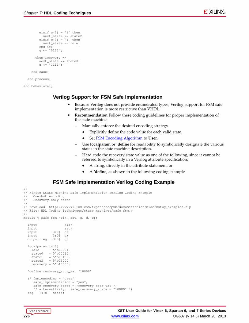
Chapter 7: HDL Coding Techniques
elsif c(2) = ’1’ thennext_state <= state2;
elsif c(3) = ’1’ thennext_state <= idle;
end if;q <= "0101";
when recovery =>next_state <= state0;q <= "1111";
end case;
end process;
end behavioral;
Verilog Suppor t for FSM Safe Implementation• Because Verilog does not provide enumerated types, Verilog support for FSM safe
implementation is more restrictive than VHDL.• Recommendation Follow these coding guidelines for proper implementation of
the state machine:– Manually enforce the desired encoding strategy.
♦ Explicitly define the code value for each valid state.♦ Set FSM Encoding Algorithm to User.
– Use localparam or ‘define for readability to symbolically designate the variousstates in the state machine description.
– Hard code the recovery state value as one of the following, since it cannot bereferred to symbolically in a Verilog attribute specification:♦ A string, directly in the attribute statement, or♦ A ‘define, as shown in the following coding example
FSM Safe Implementation Verilog Coding Example//// Finite State Machine Safe Implementation Verilog Coding Example// One-hot encoding// Recovery-only state//// Download: http://www.xilinx.com/txpatches/pub/documentation/misc/xstug_examples.zip// File: HDL_Coding_Techniques/state_machines/safe_fsm.v//module v_safe_fsm (clk, rst, c, d, q);
input clk;input rst;input [3:0] c;input [3:0] d;output reg [3:0] q;
localparam [4:0]idle = 5’b00001,state0 = 5’b00010,state1 = 5’b00100,state2 = 5’b01000,recovery = 5’b10000;
‘define recovery_attr_val "10000"
(* fsm_encoding = "user",safe_implementation = "yes",safe_recovery_state = ‘recovery_attr_val *)// alternatively: safe_recovery_state = "10000" *)
reg [4:0] state;
XST User Guide for Vir tex-6, Spar tan-6, and 7 Series Devices276 www.xilinx.com UG687 (v 14.5) March 20, 2013
Send Feedback
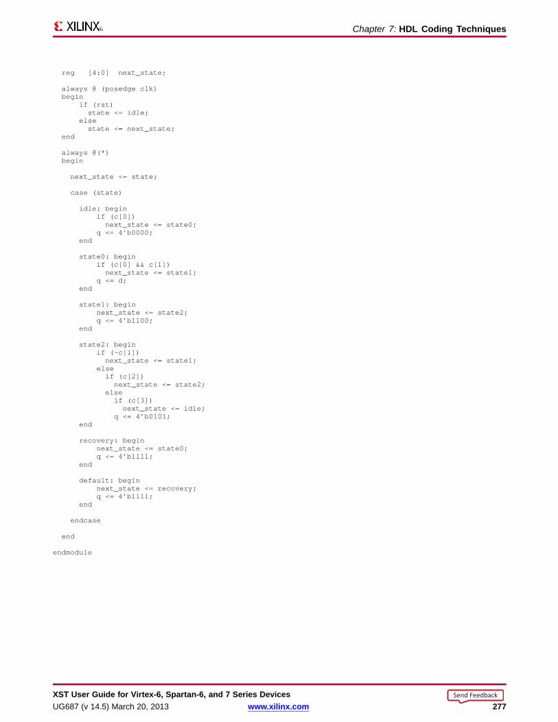
Chapter 7: HDL Coding Techniques
reg [4:0] next_state;
always @ (posedge clk)begin
if (rst)state <= idle;
elsestate <= next_state;
end
always @(*)begin
next_state <= state;
case (state)
idle: beginif (c[0])next_state <= state0;
q <= 4’b0000;end
state0: beginif (c[0] && c[1])next_state <= state1;
q <= d;end
state1: beginnext_state <= state2;q <= 4’b1100;
end
state2: beginif (~c[1])next_state <= state1;
elseif (c[2])next_state <= state2;
elseif (c[3])next_state <= idle;
q <= 4’b0101;end
recovery: beginnext_state <= state0;q <= 4’b1111;
end
default: beginnext_state <= recovery;q <= 4’b1111;
end
endcase
end
endmodule
XST User Guide for Vir tex-6, Spar tan-6, and 7 Series DevicesUG687 (v 14.5) March 20, 2013 www.xilinx.com 277
Send Feedback
Chapter 7: HDL Coding Techniques
FSM Related Constraints• Automatic FSM Extraction
• FSM Style
• FSM Encoding Algorithm
• Enumerated Encoding
• Safe Implementation
• Safe Recovery State
FSM Repor tingThe XST log provides detailed information about Finite State Machine (FSM)components and their encoding.
XST User Guide for Vir tex-6, Spar tan-6, and 7 Series Devices278 www.xilinx.com UG687 (v 14.5) March 20, 2013
Send Feedback

Chapter 7: HDL Coding Techniques
FSM Repor ting Example=========================================================================* HDL Synthesis *=========================================================================
Synthesizing Unit <fsm_1>.Found 1-bit register for signal <outp>.Found 2-bit register for signal <state>.Found finite state machine <FSM_0> for signal <state>.-----------------------------------------------------------------------| States | 4 || Transitions | 5 || Inputs | 1 || Outputs | 2 || Clock | clk (rising_edge) || Reset | reset (positive) || Reset type | asynchronous || Reset State | s1 || Power Up State | s1 || Encoding | gray || Implementation | LUT |-----------------------------------------------------------------------Summary:
inferred 1 D-type flip-flop(s).inferred 1 Finite State Machine(s).Unit <fsm_1> synthesized.
=========================================================================HDL Synthesis Report
Macro Statistics# Registers : 11-bit register : 1# FSMs : 1
=========================================================================
=========================================================================* Advanced HDL Synthesis *=========================================================================
=========================================================================Advanced HDL Synthesis Report
Macro Statistics# FSMs : 1# Registers : 1Flip-Flops : 1# FSMs : 1
=========================================================================
=========================================================================* Low Level Synthesis *=========================================================================Optimizing FSM <state> on signal <state[1:2]> with gray encoding.-------------------State | Encoding-------------------s1 | 00s2 | 11s3 | 01s4 | 10-------------------
FSM Coding ExamplesFor update information, see “Coding Examples” in the Introduction.
XST User Guide for Vir tex-6, Spar tan-6, and 7 Series DevicesUG687 (v 14.5) March 20, 2013 www.xilinx.com 279
Send Feedback
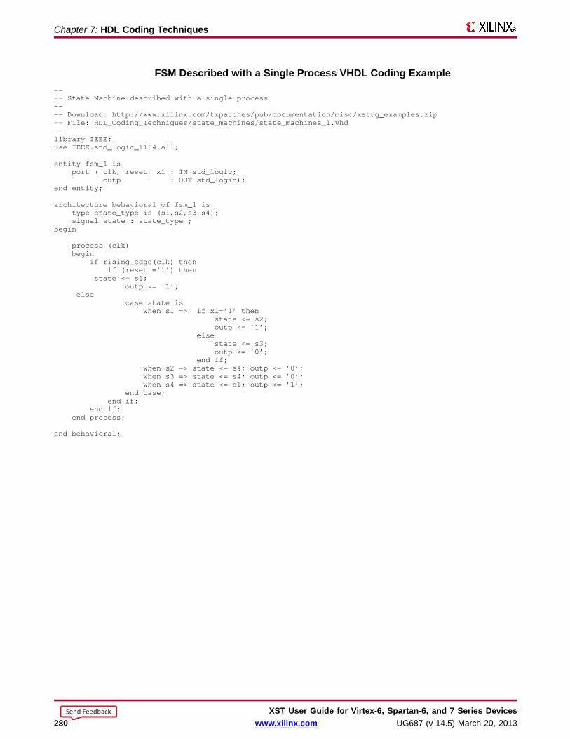
Chapter 7: HDL Coding Techniques
FSM Described with a Single Process VHDL Coding Example---- State Machine described with a single process---- Download: http://www.xilinx.com/txpatches/pub/documentation/misc/xstug_examples.zip-- File: HDL_Coding_Techniques/state_machines/state_machines_1.vhd--library IEEE;use IEEE.std_logic_1164.all;
entity fsm_1 isport ( clk, reset, x1 : IN std_logic;
outp : OUT std_logic);end entity;
architecture behavioral of fsm_1 istype state_type is (s1,s2,s3,s4);signal state : state_type ;
begin
process (clk)begin
if rising_edge(clk) thenif (reset =’1’) then
state <= s1;outp <= ’1’;
elsecase state is
when s1 => if x1=’1’ thenstate <= s2;outp <= ’1’;
elsestate <= s3;outp <= ’0’;
end if;when s2 => state <= s4; outp <= ’0’;when s3 => state <= s4; outp <= ’0’;when s4 => state <= s1; outp <= ’1’;
end case;end if;
end if;end process;
end behavioral;
XST User Guide for Vir tex-6, Spar tan-6, and 7 Series Devices280 www.xilinx.com UG687 (v 14.5) March 20, 2013
Send Feedback

Chapter 7: HDL Coding Techniques
FSM with Three Always Bloc ks Verilog Coding Example//// State Machine with three always blocks.//// Download: http://www.xilinx.com/txpatches/pub/documentation/misc/xstug_examples.zip// File: HDL_Coding_Techniques/state_machines/state_machines_3.v//module v_fsm_3 (clk, reset, x1, outp);
input clk, reset, x1;output outp;reg outp;reg [1:0] state;reg [1:0] next_state;
parameter s1 = 2’b00; parameter s2 = 2’b01;parameter s3 = 2’b10; parameter s4 = 2’b11;
initial beginstate = 2’b00;
end
always @(posedge clk or posedge reset)begin
if (reset) state <= s1;else state <= next_state;
end
always @(state or x1)begin
case (state)s1: if (x1==1’b1)
next_state = s2;else
next_state = s3;s2: next_state = s4;s3: next_state = s4;s4: next_state = s1;
endcaseend
always @(state)begin
case (state)s1: outp = 1’b1;s2: outp = 1’b1;s3: outp = 1’b0;s4: outp = 1’b0;
endcaseend
endmodule
XST User Guide for Vir tex-6, Spar tan-6, and 7 Series DevicesUG687 (v 14.5) March 20, 2013 www.xilinx.com 281
Send Feedback

Chapter 7: HDL Coding Techniques
Black Boxes• A design can contain EDIF or NGC files generated by:
– Synthesis tools– Schematic text editors– Any other design entry mechanism
• These modules must be instantiated in order to be connected to the rest of the design.– Use Black Box instantiation in the HDL source code.– The netlist is propagated to the final top-level netlist without being processed
by XST.– XST enables you to apply specific constraints to these Black Box instantiations.
The instantiations are then passed to the NGC file.• You may have a design block for which you have a Register Transfer Level (RTL)
model, as well as your own implementation of this block in the form of an EDIFnetlist.– The RTL model is valid for simulation purposes only. Use Box Type to skip
synthesis of the RTL model and create a Black Box.– The EDIF netlist is linked to the synthesized design during NGDBuild.
• Once you make a design a Black Box, each instance of that design is a Black Box.While you can apply constraints to the instance, XST ignores any constraint appliedto the original design.
• For more information, see:– Constraints Guide (UG625)– Chapter 10, General Constraints– VHDL and Verilog language reference manuals
Black Boxes Related ConstraintsBox Type• BoxType is used for device primitive instantiation in XST.• Before using BoxType, see Device Primitive Support.
Black Boxes Repor ting• XST acknowledges a Black Box instantiation during VHDL elaboration.
WARNING:HDLCompiler:89 - "example.vhd" Line 15. <my_bbox>remains a black-box since it has no binding entity.
• XST acknowledges a Black Box instantiation during Verilog elaboration.WARNING:HDLCompiler:1498 – "example.v" Line 27: Empty module<v_my_block> remains a black box.
• When a Black Box is explicitly designated using a Box Type constraint:– XST processes it silently if the constraint value is black_box or primitive.– XST issues a message for each instantiation of the designated element if the
constraint value is user_black_boxSynthesizing Unit <my_top>. Set property "box_type =user_black_box" for instance <my_inst>. Unit <my_top >synthesized.
XST User Guide for Vir tex-6, Spar tan-6, and 7 Series Devices282 www.xilinx.com UG687 (v 14.5) March 20, 2013
Send Feedback
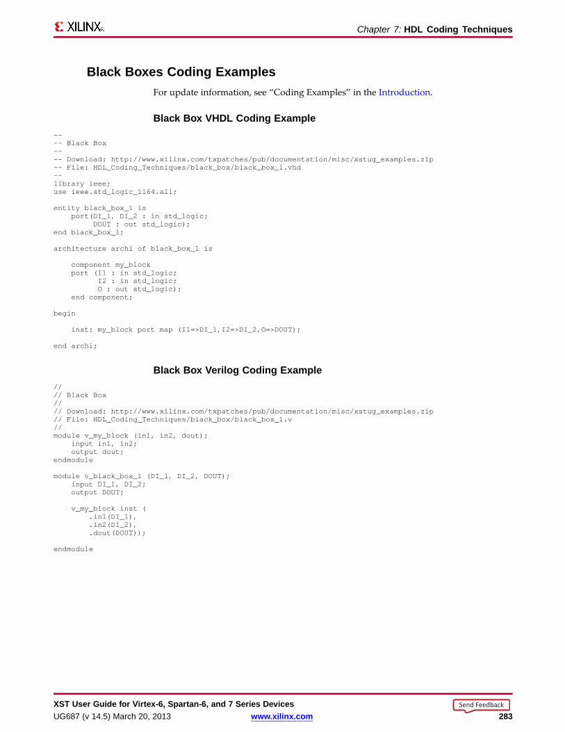
Chapter 7: HDL Coding Techniques
Black Boxes Coding ExamplesFor update information, see “Coding Examples” in the Introduction.
Black Box VHDL Coding Example---- Black Box---- Download: http://www.xilinx.com/txpatches/pub/documentation/misc/xstug_examples.zip-- File: HDL_Coding_Techniques/black_box/black_box_1.vhd--library ieee;use ieee.std_logic_1164.all;
entity black_box_1 isport(DI_1, DI_2 : in std_logic;
DOUT : out std_logic);end black_box_1;
architecture archi of black_box_1 is
component my_blockport (I1 : in std_logic;
I2 : in std_logic;O : out std_logic);
end component;
begin
inst: my_block port map (I1=>DI_1,I2=>DI_2,O=>DOUT);
end archi;
Black Box Verilog Coding Example//// Black Box//// Download: http://www.xilinx.com/txpatches/pub/documentation/misc/xstug_examples.zip// File: HDL_Coding_Techniques/black_box/black_box_1.v//module v_my_block (in1, in2, dout);
input in1, in2;output dout;
endmodule
module v_black_box_1 (DI_1, DI_2, DOUT);input DI_1, DI_2;output DOUT;
v_my_block inst (.in1(DI_1),.in2(DI_2),.dout(DOUT));
endmodule
XST User Guide for Vir tex-6, Spar tan-6, and 7 Series DevicesUG687 (v 14.5) March 20, 2013 www.xilinx.com 283
Send Feedback

XST User Guide for Vir tex-6, Spar tan-6, and 7 Series Devices284 www.xilinx.com UG687 (v 14.5) March 20, 2013
Send Feedback
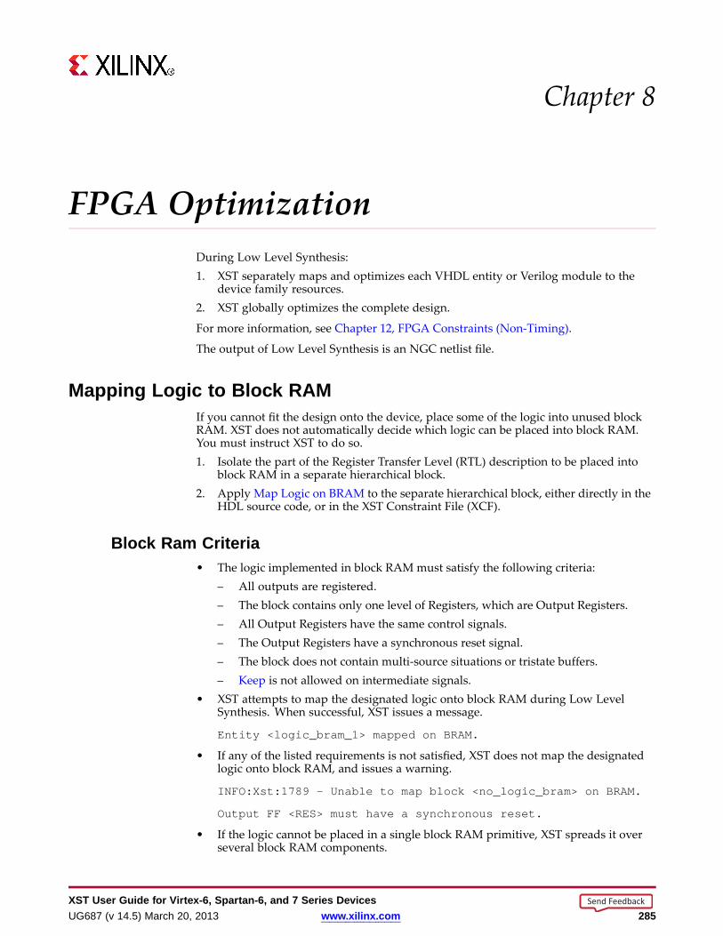
Chapter 8
FPGA OptimizationDuring Low Level Synthesis:1. XST separately maps and optimizes each VHDL entity or Verilog module to the
device family resources.2. XST globally optimizes the complete design.
For more information, see Chapter 12, FPGA Constraints (Non-Timing).
The output of Low Level Synthesis is an NGC netlist file.
Mapping Logic to Bloc k RAMIf you cannot fit the design onto the device, place some of the logic into unused blockRAM. XST does not automatically decide which logic can be placed into block RAM.You must instruct XST to do so.1. Isolate the part of the Register Transfer Level (RTL) description to be placed into
block RAM in a separate hierarchical block.2. Apply Map Logic on BRAM to the separate hierarchical block, either directly in the
HDL source code, or in the XST Constraint File (XCF).
Bloc k Ram Criteria• The logic implemented in block RAM must satisfy the following criteria:
– All outputs are registered.– The block contains only one level of Registers, which are Output Registers.– All Output Registers have the same control signals.– The Output Registers have a synchronous reset signal.– The block does not contain multi-source situations or tristate buffers.– Keep is not allowed on intermediate signals.
• XST attempts to map the designated logic onto block RAM during Low LevelSynthesis. When successful, XST issues a message.
Entity <logic_bram_1> mapped on BRAM.
• If any of the listed requirements is not satisfied, XST does not map the designatedlogic onto block RAM, and issues a warning.
INFO:Xst:1789 - Unable to map block <no_logic_bram> on BRAM.
Output FF <RES> must have a synchronous reset.
• If the logic cannot be placed in a single block RAM primitive, XST spreads it overseveral block RAM components.
XST User Guide for Vir tex-6, Spar tan-6, and 7 Series DevicesUG687 (v 14.5) March 20, 2013 www.xilinx.com 285
Send Feedback
Chapter 8: FPGA Optimization
Flip-Flop Implementation GuidelinesCLB Flip-Flops and Latches do not natively implement both a set and reset.
• If XST finds a Flip-Flop with both a set and reset:
– The set and reset is retargeted.
– Additional logic is created.
– The set and reset is rejected with an error message.
• These rules are enforced whether the Flip-Flop is inferred, or retargeted from anolder device family primitive instantiation.
Error Message ExampleERROR: XST:#### - This design infers one or more latches orregisters with both an active asynchronous set and reset. In theVirtex®-6 and Spartan®-6 architectures this behavior creates asub-optimal circuit in area, power and performance. To synthesisan optimal implementation it is highly recommended to eitherremove one set or reset or make the function synchronous. Tooverride this error set —retarget_active_async_set_reset optionto yes.
Setting or Resetting Register s Async hronousl yXilinx® does not recommend setting or resetting Registers asynchronously even thoughit is supported on Xilinx devices.
• Control set remapping is no longer possible.
• Sequential functionality in several device resources, such as the following, can beset or reset synchronously only.
– block RAM components
– DSP blocks
• If you set or reset those device resources asynchronously:
– You will be unable to leverage the resources.
OR
– The resources will be configured sub-optimally.
XST User Guide for Vir tex-6, Spar tan-6, and 7 Series Devices286 www.xilinx.com UG687 (v 14.5) March 20, 2013
Send Feedback

Chapter 8: FPGA Optimization
Xilinx Recommendations• Do not set or reset Registers asynchronously.
• Use synchronous initialization.
• If your coding guidelines call for Registers to be set or reset asynchronously, runXST with Asynchronous to Synchronous to assess the potential benefits of usingsynchronous set or reset.
– Asynchronous to Synchronous affects inferred Registers only.
– Asynchronous to Synchronous does not affect instantiated Flip-Flops.
• Do not describe Flip-Flops with both a set and a reset.
– None of the available Flip-Flop primitives natively features both a set and areset, whether synchronous or asynchronous.
– XST rejects Flip-Flops described with both an asynchronous reset and anasynchronous set.
• Avoid operational set and reset logic whenever possible. There may be other, lessexpensive, ways to achieve the desired result, such as taking advantage of the circuitglobal reset by defining an initial contents.
• Always describe the clock enable, set and reset control inputs of Xilinx Flip-Flopprimitives as active-High. Describing the control inputs as active-Low leads toinverter logic that penalizes circuit performance.
XST User Guide for Vir tex-6, Spar tan-6, and 7 Series DevicesUG687 (v 14.5) March 20, 2013 www.xilinx.com 287
Send Feedback

Chapter 8: FPGA Optimization
Flip-Flop Retiming• Flip-Flop retiming moves Flip-Flops and Latches across logic in order to:
– Reduce synchronous paths
– Increase clock frequency
• Flip-Flop retiming is disabled by default.
• Design behavior does not change. Only timing delays are modified.
Forwar d and Backward Flip-Flop Retiming• Forward Flip-Flop retiming:
– Moves a set of Flip-Flops that are the input of a LUT to a single Flip-Flop at itsoutput.
– Generally reduces the number of Flip-Flops.
• Backward Flip-Flop retiming:
– Moves a single Flip-Flop that is at the output of a LUT to a set of Flip-Flops atits input.
– Generally increases the number of Flip-Flop, sometimes significantly.
Forwar d and Backward Flip-Flop Retiming Summar yRetiming Flip-Flops At Becomes AtForward Set Input Single Output
Backward Single Output Set Input
Global Optimization• Flip-Flop retiming is part of global optimization.
• Flip-Flop retiming respects the same constraints as all other optimization techniques.
• Flip-Flop retiming is incremental.
A Flip-Flop that is the result of a retiming can be moved again in the same direction(forward or backward) if it results in better timing.
• Flip-Flop retiming iterations stop when:
– The timing constraints are satisfied, or
– No more timing improvement can be obtained.
Flip-Flop MessagesFor each Flip-Flop moved, a message specifies:
• The original and new Flip-Flop names
• Whether it is a forward or backward retiming
XST User Guide for Vir tex-6, Spar tan-6, and 7 Series Devices288 www.xilinx.com UG687 (v 14.5) March 20, 2013
Send Feedback

Chapter 8: FPGA Optimization
Limitations of Flip-Flop RetimingFlip-Flop retiming does not take place under the following circumstances.• Flip-Flop retiming is not applied to Flip-Flops with an IOB=TRUE property.• Forward Flip-Flop retiming does not take place if a Flip-Flop (or the signal on its
output) has a Keep property.• Backward Flip-Flop retiming does not take place if a Flip-Flop (or the signal on
its input) has a Keep property.• Instantiated Flip-Flops are moved only if Optimize Instantiated Primitives is set to
yes.• Flip-Flops are moved across instantiated primitives only if Optimize Instantiated
Primitives is set to yes.• Flip-Flops with both a set and a reset are not moved.
Contr olling Flip-Flop RetimingThe following constraints control Flip-Flop retiming:• Register Balancing• Move First Stage• Move Last Stage
Speed Optimization Under Area ConstraintThe Slice (LUT-FF Pairs) Utilization Ratio constraint:• Does not control macro inference.• Allows some control over circuit performance even when instructing XST to use
area reduction as its main goal.• Is set by default to 100% of the selected device size.• Influences low level optimization.
– If the estimated area is higher than the constraint requirement, XST tries tofurther reduce area.
– When the estimated area falls within the constraint requirement, XST looksfor timing optimization opportunities in which the solution meets the areaconstraint requirement.
Low Level Synthesis Repor t Example One (100%)Found area constraint ratio of 100 (+ 5) on block tge, actualratio is 102. Optimizing block tge> to meet ratio 100 (+ 5) of1536 slices Area constraint is met for block tge>, final ratiois 95.
In this report example:• The area constraint target was set to 100%.• The initial area estimation found an actual device utilization of 102%.• XST began optimization and reached 95%.
Low Level Synthesis Repor t Example Two (70%)Found area constraint ratio of 70 (+ 5) on block fpga_hm, actualratio is 64. Optimizing block fpga_hm> to meet ratio 70 (+ 5) of1536 slices : WARNING:Xst - Area constraint could not be met forblock tge>, final ratio is 94
XST User Guide for Vir tex-6, Spar tan-6, and 7 Series DevicesUG687 (v 14.5) March 20, 2013 www.xilinx.com 289
Send Feedback
Chapter 8: FPGA Optimization
In this report example:• The area constraint target was set to 70%.• The area constraint target was not met.• If the area constraint target cannot be met:
– XST ignores it during timing optimization.– XST runs low level synthesis to achieve the best frequency.
• Because XST was unable to meet the area constraint target, XST issued a warning.WARNING:Xst - Area constraint could not be met for block tge>,final ratio is 94
• (+5) represents the Max Margin of the area constraint.– If the area constraint is not met, and– If the difference between (requested area) and (actual area) is (less than or
equal to 5%):♦ XST runs timing optimization taking into account the achieved area.♦ XST makes sure that the final area solution does not exceed that figure.
Low Level Synthesis Repor t Example Three (55%)Found area constraint ratio of 55 (+ 5) on block fpga_hm, actualratio is 64. Optimizing block fpga_hm> to meet ratio 55 (+ 5) of1536 slices : Area constraint is met for block fpga_hm>, finalratio is 60.
In this report example:• The target area was set to 55%.• XST achieved 60%.• Since the difference between (requested area) and (achieved area) is (not more than
5%):– XST considers that the area constraint was met.– XST ensures that it is not broken by further optimizations
Disab ling Automatic Resour ce Management• To disable automatic resource management, specify -1 as the value for Slice (LUT-FF
Pairs) Utilization Ratio.• You can apply Slice (LUT-FF Pairs) Utilization Ratio to a specific block.• You can specify:
– An absolute number of slices (or FF-LUT pairs), or– A percentage of the total number available on the device
Implementation Constraints• XST writes all implementation constraints in the following to the output NGC file.
– HDL source code– XST Constraint File (XCF)
• XST generates Keep properties during buffer insertion for:– Maximum fanout control, or– Optimization
XST User Guide for Vir tex-6, Spar tan-6, and 7 Series Devices290 www.xilinx.com UG687 (v 14.5) March 20, 2013
Send Feedback

Chapter 8: FPGA Optimization
Device Primitive Suppor tXST allows you to instantiate Xilinx® device primitives directly in the HDL source code.
• The instantiated primitives are:
– Pre-compiled in the UNISIM library.
– Not automatically optimized or changed by XST.
– Preserved by XST and made available in the final NGC netlist.
• The Optimize Instantiated Primitives constraint allows XST to attempt to optimizeinstantiated primitives with the rest of the design. Timing information isavailable for most primitives. This allows XST to perform efficient timing-drivenoptimizations.
• In order to simplify instantiation of complex primitives such as RAM components,XST supports the UniMacro library.
For more information, see the Libraries Guides.
Generating Primitives Through Attrib utesSome primitives can be generated through attributes.
Buff er TypeTo force the use of a specific buffer type, assign Buffer Type to:
• Circuit primary I/Os, or
• Internal signals.
Use Buffer Type to disable buffer insertion.
I/O Standar dUse I/O Standard to assign an I/O standard to an I/O primitive.
For example, the following code assigns PCI33_5 I/O standard to the I/O port.
// synthesis attribute IOSTANDARDof in1 is PCI33_5
Primitives and Black BoxesPrimitive support is based on the concept of the Black Box.
For information on the basics of Black Box support, see FSM Safe Implementation.
XST User Guide for Vir tex-6, Spar tan-6, and 7 Series DevicesUG687 (v 14.5) March 20, 2013 www.xilinx.com 291
Send Feedback

Chapter 8: FPGA Optimization
Primitive and Black Box ExampleThis example illustrates a significant difference between Black Box and primitivesupport.
• Assume a design with a submodule called MUXF5. The MUXF5 can be your ownfunctional block or a Xilinx® device primitive.
• To avoid confusion about how XST interprets this module, attach Box Type to thecomponent declaration of MUXF5.
• If BoxType is applied to the MUXF5 with a value of:
– primitive or black_box
XST interprets the module as a Xilinx device primitive and uses its parametersin, for example, critical path estimation.
– user_black_box
XST processes the module as a regular user Black Box.
• If user_black_box has the same name as that of a Xilinx device primitive:
– XST renames user_black_box to a unique name.
– XST issues a warning.
For example, if MUX5 is renamed to MUX51, XST issues the following warning.
WARNING:Xst:79 - Model ’muxf5’ has differentcharacteristics in destination library WARNING:Xst:80 -Model name has been changed to ’muxf51’
• If Box Type is not applied to MUXF5, XST processes the block as a user hierarchicalblock.
• If user_black_box has the same name as that of a Xilinx device primitive:
– XST renames user_black_box to a unique name.
– XST issues a warning.
XST User Guide for Vir tex-6, Spar tan-6, and 7 Series Devices292 www.xilinx.com UG687 (v 14.5) March 20, 2013
Send Feedback

Chapter 8: FPGA Optimization
Device Primitives LibrariesVHDL and Verilog libraries simplify the instantiation of Xilinx® device primitives.
• These libraries contain the complete set of Xilinx device primitive declarations.
• Box Type is applied to each component.
• If you have included these libraries, you need not apply Box Type yourself.
VHDL Device Primitives Libraries• Declare library UNISIM with its package vcomponents in the HDL source code.
library unisim;use unisim.vcomponents.all;
• The HDL source code is located in the following XST installation file:
vhdl\src\ unisims\unisims_vcomp.vhd
Verilog Device LibrariesThe Verilog UNISIM library is precompiled. XST links it with your design.
Device Primitives InstantiationUse uppercase for generic (VHDL) and parameter (Verilog) values when instantiatingdevice primitives.
Instantiating Device Primitives ExampleThe ODDR element has the following component declaration in the UNISIM library.
component ODDRgeneric (
DDR_CLK_EDGE: string := "OPPOSITE_EDGE";INIT : bit := ’0’;SRTYPE : string := "SYNC");
port(Q : out std_ulogic;C : in std_ulogic;CE : in std_ulogic;D1 : in std_ulogic;D2 : in std_ulogic;R : in std_ulogic;S : in std_ulogic);
end component;
• The values of DDR_CLK_EDGE and SRTYPE must be in uppercase when youinstantiate this primitive.
• If the values are not in uppercase, XST issues a warning stating that unknown valuesare used.
Using INITSome primitives, such as LUT1, enable you to use an INIT during instantiation.
XST User Guide for Vir tex-6, Spar tan-6, and 7 Series DevicesUG687 (v 14.5) March 20, 2013 www.xilinx.com 293
Send Feedback

Chapter 8: FPGA Optimization
To pass an INIT to the final netlist:
• Apply INIT to the instantiated primitive, or
• Pass INIT with:
– generics (VHDL), or
– parameters (Verilog)
Passing the INIT to the final netlist allows you to use the same code for synthesis andsimulation.
Specifying Primitive Proper tiesUse VHDL generics or Verilog parameters to specify properties on instantiatedprimitives (for example, the INIT of an instantiated LUT).
• You can override the default values of instantiated primitives only with VHDLgenerics or Verilog parameters. XST issues an error message if you use anothermethod.
ERROR:Xst:3003 - “example.vhd". Line 77. Unable to setattribute "A_INPUT" with value "CASCADE" on instance <idsp>of block <DSP48E1>. This property is already defined withvalue “DIRECT" on the block definition by a VHDL generic or aVerilog parameter. Apply the desired value by overriding thedefault VHDL generic or Verilog parameter. Using an attributeis not allowed.
• Simulation tools recognize generics and parameters, simplifying the circuitvalidation process.
Configuring a LUT2 Primitive INIT Proper ty VHDL Coding Example---- Instantiating a LUT2 primitive-- Configured via the generics mechanism (recommended)---- Download: http://www.xilinx.com/txpatches/pub/documentation/misc/xstug_examples.zip-- File: FPGA_Optimization/primitive_support/primitive_2.vhd--library ieee;use ieee.std_logic_1164.all;
library unisim;use unisim.vcomponents.all;
entity primitive_2 isport(I0,I1 : in std_logic;
O : out std_logic);end primitive_2;
architecture beh of primitive_2 isbegin
inst : LUT2generic map (INIT=>"1")port map (I0=>I0, I1=>I1, O=>O);
end beh;
XST User Guide for Vir tex-6, Spar tan-6, and 7 Series Devices294 www.xilinx.com UG687 (v 14.5) March 20, 2013
Send Feedback
Chapter 8: FPGA Optimization
Configuring a LUT2 Primitive INIT Proper ty Verilog Coding Example//// Instantiating a LUT2 primitive// Configured via the parameter mechanism//// Download: http://www.xilinx.com/txpatches/pub/documentation/misc/xstug_examples.zip// File: FPGA_Optimization/primitive_support/primitive_2.v//module v_primitive_2 (I0,I1,O);
input I0,I1;output O;
LUT2 #(4’h1) inst (.I0(I0), .I1(I1), .O(O));
endmodule
Primitives Repor tingBox Type with its value (primitive) is applied to each primitive in the UNISIM library.XST therefore processes instantiated device primitives silently.
XST WarningsXST issues a warning if either of the following two conditions exists.
First Warning Condition• You instantiate a block (non primitive).
AND
• The block has no content (no logic description).
Second Warning Condition• The block has a logic description.
AND
• You apply Box Type to it with a value of user_black_box.
Warning ExampleElaborating entity <example> (architecture <archi>) fromlibrary <work>. WARNING:HDLCompiler:89 - "example.vhd" Line 15:<my_block> remains a black-box since it has no binding entity.
Primitives Related Constraints• Box Type
• Constraints for placement and routing that can be passed from the HDL source codeto the NGC file without any specific XST processing
Primitives Coding ExamplesFor update information, see “Coding Examples” in the Introduction.
XST User Guide for Vir tex-6, Spar tan-6, and 7 Series DevicesUG687 (v 14.5) March 20, 2013 www.xilinx.com 295
Send Feedback
Chapter 8: FPGA Optimization
Instantiating and Configuring a LUT2 Primitive with a Generic VHDLCoding Example
---- Instantiating a LUT2 primitive-- Configured via the generics mechanism (recommended)---- Download: http://www.xilinx.com/txpatches/pub/documentation/misc/xstug_examples.zip-- File: FPGA_Optimization/primitive_support/primitive_2.vhd--library ieee;use ieee.std_logic_1164.all;
library unisim;use unisim.vcomponents.all;
entity primitive_2 isport(I0,I1 : in std_logic;
O : out std_logic);end primitive_2;
architecture beh of primitive_2 isbegin
inst : LUT2generic map (INIT=>"1")port map (I0=>I0, I1=>I1, O=>O);
end beh;
Instantiating and Configuring a LUT2 Primitive with a Parameter VerilogCoding Example
//// Instantiating a LUT2 primitive// Configured via the parameter mechanism//// Download: http://www.xilinx.com/txpatches/pub/documentation/misc/xstug_examples.zip// File: FPGA_Optimization/primitive_support/primitive_2.v//module v_primitive_2 (I0,I1,O);
input I0,I1;output O;
LUT2 #(4’h1) inst (.I0(I0), .I1(I1), .O(O));
endmodule
Instantiating and Configuring a LUT2 Primitive with a Defparam VerilogCoding Example
//// Instantiating a LUT2 primitive// Configured via the defparam mechanism//// Download: http://www.xilinx.com/txpatches/pub/documentation/misc/xstug_examples.zip// File: FPGA_Optimization/primitive_support/primitive_3.v//module v_primitive_3 (I0,I1,O);
input I0,I1;output O;
LUT2 inst (.I0(I0), .I1(I1), .O(O));defparam inst.INIT = 4’h1;
endmodule
XST User Guide for Vir tex-6, Spar tan-6, and 7 Series Devices296 www.xilinx.com UG687 (v 14.5) March 20, 2013
Send Feedback

Chapter 8: FPGA Optimization
Using the UniMacr o Librar y• XST supports a library called UniMacro.
• The UniMacro library simplifies instantiation of complex primitives such as RAMcomponents.
• For more information, see the Libraries Guides.
Using the UniMacr o Librar y (VHDL)• Declare library unimacro with its package vcomponents.
library unimacro;use unimacro.vcomponents.all;
• The HDL source code of this package is located in the Xilinx® software installation.
vhdl\src\unisims\unisims_vcomp.vhd
Using the UniMacr o Librar y (Verilog)• The UniMacro library is precompiled.
• XST automatically links the UniMacro library with your design.
XST User Guide for Vir tex-6, Spar tan-6, and 7 Series DevicesUG687 (v 14.5) March 20, 2013 www.xilinx.com 297
Send Feedback
Chapter 8: FPGA Optimization
Cores ProcessingCores processing includes:• Loading Cores• Finding Cores• Cores Reporting
Loading Cores• XST can read cores in the form of EDIF or NGC netlist files to achieve more accurate:
– Timing estimation– Resource utilization control
• The optimize value allows XST to:– Integrate the core netlist into the overall design.– Attempt to optimize it.
• Enable or disable Load Cores as follows:– ISE® Design Suite
Process > Properties > Synthesis Options > Read Cores– Command Line Mode
-read_cores
Finding CoresXST automatically finds cores in the ISE® Design Suite project directory.• If the cores are located in a different directory, specify the path as follows:
– ISE Design SuiteProcess > Properties > Synthesis Options > Core Search Directories
– Command Line ModeCores Search Directories
• Xilinx® recommends that you:– Systematically specify the directories in which the cores reside.– Keep this information up to date.
• Follow these recommendations to:– Obtain better timing and resource estimation.– Protect against unexpected behaviors and hard-to-debug situations.
For example, without knowing the contents of an unloaded core (seen as a BlackBox), XST may have difficulty determining adequate buffer insertions on pathsleading to that core. This can negatively impact timing closure.
Cores Repor tingCores Repor ting ExampleLauncher: Executing edif2ngd -noa "my_add.edn" "my_add.ngo"INFO:NgdBuild - Release 11.2 - edif2ngd INFO:NgdBuild - Copyright(c) 1995-2010 Xilinx, Inc. All rights reserved. Writing thedesign to "my_add.ngo"... Loading core <my_add> for timing andarea information for instance <inst>.
XST User Guide for Vir tex-6, Spar tan-6, and 7 Series Devices298 www.xilinx.com UG687 (v 14.5) March 20, 2013
Send Feedback

Chapter 8: FPGA Optimization
Mapping Logic to LUTsUse the UNISIM library to directly instantiate LUT components in the HDL source code.
• To specify a function that a LUT must execute, apply INIT to the instance of the LUT.
• To place an instantiated LUT or Register in a specific slice of the chip, attach RLOCto the same instance.
• Since it is not always convenient to calculate INIT functions, you can use an alternatemethod.
1. Describe the function that you want to map onto a single LUT in the HDLsource code in a separate block.
2. Attach Map Entity on a Single LUT to this block to instruct XST that the blockmust be mapped on a single LUT.
3. XST calculates the INIT value for the LUT and preserves the LUT duringoptimization.
• XST recognizes the Synplify xc_map attribute.
• If a function cannot be mapped on a single LUT, XST errors out.
ERROR:Xst:1349 - Failed to map xcmap entity <v_and_one> in onelut.
XST User Guide for Vir tex-6, Spar tan-6, and 7 Series DevicesUG687 (v 14.5) March 20, 2013 www.xilinx.com 299
Send Feedback

Chapter 8: FPGA Optimization
Mapping Logic to LUTs Verilog Coding ExampleIn this coding example, the top block instantiates two AND gates
• The AND gates are described in blocks and_one and and_two.
• XST generates two LUT2s and does not merge them.
//// Mapping of Logic to LUTs with the LUT_MAP constraint// Mapped to 2 distinct LUT2s// Mapped to 1 single LUT3 if LUT_MAP constraints are removed//// Download: http://www.xilinx.com/txpatches/pub/documentation/misc/xstug_examples.zip// File: FPGA_Optimization/lut_mapping/lut_map_1.v//
(* LUT_MAP="yes" *)module v_and_one (A, B, REZ);
input A, B;output REZ;
and and_inst(REZ, A, B);
endmodule
// --------------------------------------------------
(* LUT_MAP="yes" *)module v_and_two (A, B, REZ);
input A, B;output REZ;
or or_inst(REZ, A, B);
endmodule
// --------------------------------------------------
module v_lut_map_1 (A, B, C, REZ);input A, B, C;output REZ;
wire tmp;
v_and_one inst_and_one (A, B, tmp);v_and_two inst_and_two (tmp, C, REZ);
endmodule
XST User Guide for Vir tex-6, Spar tan-6, and 7 Series Devices300 www.xilinx.com UG687 (v 14.5) March 20, 2013
Send Feedback

Chapter 8: FPGA Optimization
Contr olling Placement on the Device• You can control placement of the following inferred macros to a specific location
on the device:
– Registers
– Block RAM components
• To control placement of the macros, apply RLOC to the signal modeling the Registeror the block RAM. See the coding examples below.
• When RLOC is applied on a Register:
– XST distributes RLOC to each Flip-Flop.
– XST propagates RLOC constraints to the final netlist.
• XST supports RLOC for inferred RAMs that can be implemented with a singleblock RAM primitive.
RLOC Constraint on a 4-Bit Register VHDL Coding ExampleThis coding example specifies an RLOC constraint on a 4-bit Register:
---- Specification of INIT and RLOC values for a flip-flop, described at RTL level---- Download: http://www.xilinx.com/txpatches/pub/documentation/misc/xstug_examples.zip-- File: FPGA_Optimization/inits_and_rlocs/inits_rlocs_3.vhd--library ieee;use ieee.std_logic_1164.all;
entity inits_rlocs_3 isport (CLK : in std_logic;
DI : in std_logic_vector(3 downto 0);DO : out std_logic_vector(3 downto 0));
end inits_rlocs_3;
architecture beh of inits_rlocs_3 issignal tmp: std_logic_vector(3 downto 0):="1011";
attribute RLOC: string;attribute RLOC of tmp: signal is "X3Y0 X2Y0 X1Y0 X0Y0";
begin
process (CLK)begin
if (clk’event and clk=’1’) thentmp <= DI;
end if;end process;
DO <= tmp;
end beh;
XST User Guide for Vir tex-6, Spar tan-6, and 7 Series DevicesUG687 (v 14.5) March 20, 2013 www.xilinx.com 301
Send Feedback

Chapter 8: FPGA Optimization
Inser ting Buff ers• XST automatically inserts clock and I/O buffers.
• Use Add I/O Buffers to enable or disable automatic insertion.
• Automatic insertion is enabled by default.
• You can manually instantiate clock and I/O buffers.
• XST does not change instantiated device primitives, but propagates them to thefinal netlist.
Using the PCI Flow With XSTFollow these guidelines to satisfy placement constraints and meet timing requirementswhen using the PCI™ flow with XST.
1. Set the case of the names in the generated netlist to:
• uppercase (VHDL)
– The default is lowercase.
– Specify the case in ISE® Design Suite.
Process > Properties > Synthesis Options > Case
• maintain (Verilog)
– The default is maintain.
– Specify the case in ISE Design Suite.
Process > Properties > Synthesis Options > Case
2. Preserve the design hierarchy.
Specify the Keep Hierarchy setting in ISE Design Suite.
Process > Properties > Synthesis Options > Keep Hierarchy
3. Preserve equivalent Flip-Flops.
• XST removes equivalent Flip-Flops by default.
• Specify the Equivalent Register Removal setting in ISE Design Suite.
Process > Properties > Xilinx Specific Options > Equivalent Register Removal
Preventing Logic and Flip-Flop ReplicationTo prevent logic and Flip-Flop replication caused by a high fanout Flip-Flop set/resetsignal:
• Set a high maximum fanout value for the entire design in ISE® Design Suite.
Process > Properties > Xilinx Specific Options > Max Fanout
OR
• Set a high maximum fanout value for the initialization signal connected to the RSTport of the PCI™ core. Use Max Fanout. For example:
max_fanout=2048
XST User Guide for Vir tex-6, Spar tan-6, and 7 Series Devices302 www.xilinx.com UG687 (v 14.5) March 20, 2013
Send Feedback

Chapter 8: FPGA Optimization
Disab ling Read CoresXST reads PCI™ cores by default for timing and area estimation.
• When reading PCI cores, XST may perform logic optimizations which:
– Do not allow the design to meet timing.
– Cause errors during MAP.
• Uncheck (disable) Read Cores in ISE® Design Suite to prevent XST from loadingthe PCI cores.
Process > Properties > Synthesis Options > Read Cores
XST User Guide for Vir tex-6, Spar tan-6, and 7 Series DevicesUG687 (v 14.5) March 20, 2013 www.xilinx.com 303
Send Feedback

XST User Guide for Vir tex-6, Spar tan-6, and 7 Series Devices304 www.xilinx.com UG687 (v 14.5) March 20, 2013
Send Feedback

Chapter 9
Design ConstraintsXST design constraints help you:
• Meet design goals.
• Obtain the best circuit implementation.
• Control aspects of:
– Synthesis
– Placement
– Routing
Xilinx® has tuned default synthesis algorithms and heuristics to provide optimal resultsfor your designs. If initial synthesis fails to meet your design goals, use the XST designconstraints to try other synthesis alternatives.
Specifying ConstraintsUse the following to specify constraints:
• ISE® Design Suite
• The command line
• VHDL attributes
• Verilog attributes and Verilog meta comments
• XST Constraint File (XCF)
Not all constraints can be specified with all tools or methods. If a tool or method is notlisted for a particular constraint, you cannot specify the constraint with it.
ISE Design Suite and the Command LineTo globally control most aspects of synthesis, specify constraints in:
• ISE Design Suite
• The run command in command line mode
XST User Guide for Vir tex-6, Spar tan-6, and 7 Series DevicesUG687 (v 14.5) March 20, 2013 www.xilinx.com 305
Send Feedback
Chapter 9: Design Constraints
VHDL Attrib utes• To specify constraints in VHDL:
1. Insert VHDL attributes directly into the HDL source code.
2. Apply the VHDL attributes to individual design elements.
• VHDL attributes allows you to control:
– Synthesis
– Placement
– Routing
• You cannot use VHDL attributes to define the properties of instantiated deviceprimitives. Use VHDL generics or Verilog parameters instead.
Verilog Attrib utes and Meta CommentsTo specify constraints in Verilog, insert Verilog attributes and meta comments into theHDL source code.
• Verilog attributes are preferred over Verilog meta comments.
• You cannot use Verilog attributes or meta comments to define the properties ofinstantiated device primitives. Use VHDL generics or Verilog parameters instead.
XST Constraint File (XCF)You can specify constraints in an XST Constraint File (XCF).
You cannot use an XCF to define the properties of instantiated device primitives. UseVHDL generics or Verilog parameters instead.
More InformationFor more information, see:
• Specifying Primitive Properties
How to specify the properties of instantiated device primitives.
• Constraints Precedence Rules
How XST determines which constraint to apply when multiple instances of thesame constraint are:
– Set using different entry methods, or
– Set on different objects.
Constraints Precedence RulesXST follows different constraints precedence rules depending on whether conflictingconstraints are:
• Set on the same object using different entry methods.
• Set on different objects.
XST User Guide for Vir tex-6, Spar tan-6, and 7 Series Devices306 www.xilinx.com UG687 (v 14.5) March 20, 2013
Send Feedback
Chapter 9: Design Constraints
Constraints Set Using Diff erent Entr y MethodsConstraints set on the same object using different entry methods take precedence asfollows. The order shown is from highest to lowest.
1. XST Constraint File (XCF)
2. HDL attribute
3. ISE® Design Suite in Process > Properties, or the command line
Constraints Set on Diff erent ObjectsConstraints set on different objects take precedence as follows.
• A local specification overrides a global specification.
• A constraint set on a signal or instance takes precedence over that same constraintset on the design unit that contains it.
Setting Synthesis OptionsSet XST synthesis options as follows:
• Setting Synthesis Options in ISE Design Suite
• Setting Other Command Line Synthesis Options
• Setting Synthesis Options for Non-Default Design Goals and Strategies
Setting Synthesis Options in ISE Design Suite• To set XST synthesis options in ISE® Design Suite:
1. Select an HDL source file from the Hierarchy panel of the Design window.
a. Right-click Synthesize-XST in the Processes panel.
b. Select Process > Properties.
c. Select a category:
– Synthesis Options
– HDL Options
– Xilinx® Specific Options
2. Set the Property display level to:
a. Standard
Most common options.
b. Advanced
All available options.
3. Check Display switch names to see the corresponding command line switchname for each option.
• Click Default to revert to the XST ISE Design Suite default options.
XST User Guide for Vir tex-6, Spar tan-6, and 7 Series DevicesUG687 (v 14.5) March 20, 2013 www.xilinx.com 307
Send Feedback

Chapter 9: Design Constraints
Setting Other Command Line Synthesis OptionsYou can set other XST command line synthesis options in addition to the default optionslisted in ISE® Design Suite in Process > Properties.
1. Select Process > Properties > Synthesis Options.2. In Other XST Command Line Options, select the command line options in the
corresponding Value field.3. Separate multiple options with a space.4. Follow the syntax described in XST Commands.
Setting Synthesis Options for Non-Default Design Goals andStrategies
ISE® Design Suite features predefined goals and strategies that allow you to run XSTwith specific options settings.• These settings have been tuned for specific optimization goals.• This approach may be a good alternative for trying non-default constraints settings,
without having to go into the details of all XST constraints.• To create and save your own design goals and strategies, select Project > Design
Goals & Strategies.
VHDL Attrib utesUse VHDL attributes to describe constraints directly in the HDL source code.• The attribute type defines the type of the attribute value.• The only allowed type for XST is string.• An attribute is declared in an entity or architecture.• An attribute declared in the architecture cannot also be used in the entity declaration.• The object list is a comma separated list of identifiers.• Accepted object types are:
– Entity– Architecture– Component– Label– Signal– Variable– Type
• If a constraint can be applied on a VHDL entity, it can also be applied on thecomponent declaration.
VHDL Attrib ute Declaration Exampleattribute AttributeName : Type ;
VHDL Attrib ute Specification Exampleattribute AttributeName of ObjectList : ObjectType isAttributeValue ;
XST User Guide for Vir tex-6, Spar tan-6, and 7 Series Devices308 www.xilinx.com UG687 (v 14.5) March 20, 2013
Send Feedback

Chapter 9: Design Constraints
VHDL Attrib ute Syntax Exampleattribute RLOC : string ;
VHDL Attrib ute Exampleattribute RLOC of u123 : label is “R11C1.S0” ;attribute bufg of my_signal : signal is “sr”;
XST User Guide for Vir tex-6, Spar tan-6, and 7 Series DevicesUG687 (v 14.5) March 20, 2013 www.xilinx.com 309
Send Feedback
Chapter 9: Design Constraints
Verilog-2001 Attrib utesXST supports Verilog-2001 attribute statements.• Verilog-2001 attribute statements:
– Pass information to applications such as synthesis tools.– Are specified anywhere for operators and signals within:
♦ Module declarations♦ Instantiations
• XST ignores other attribute declarations even though the compiler may supportthem.
• Use Verilog attributes to:– Set constraints on individual objects such as:
♦ Modules♦ Instances♦ Nets
– Set the following synthesis constraints:♦ Full Case♦ Parallel Case
Verilog-2001 Syntax(* attribute_name = attribute_value *)
• The attributes are enclosed between asterisks.• attribute_value is a string. No integer or scalar values are allowed.• attribute_value is enclosed between quotes.• The default value is 1. (* attribute_name *) is equivalent to (* attribute_name = "1" *).
Attrib ute PlacementThe attributes may be placed using any of the following methods.1. Place the attribute immediately before the signal, module, or instance declaration.
• The attribute is on the same line as the declaration.
(* ram_extract = “yes” *) reg [WIDTH-1:0] myRAM[SIZE-1:0];
• The attribute is on a separate line from the declaration.
(* ram_extract = “yes” *)reg [WIDTH-1:0] myRAM[SIZE-1:0];
2. Specify a list of several attributes attached to the same Verilog object.• The attributes are separated by commas.
(* attribute_name1 = attribute_value1, attribute_name2 = attribute_value2 *)
• The attributes are enclosed in parentheses.
(* attribute_name1 = attribute_value1 *) (*attribute_name2 = attribute_value2 *)
• The attribute list spans multiple lines for improved readability.
(* ram_extract = “yes”,ram_style = “block” *)reg [WIDTH-1:0] myRAM[SIZE-1:0]
XST User Guide for Vir tex-6, Spar tan-6, and 7 Series Devices310 www.xilinx.com UG687 (v 14.5) March 20, 2013
Send Feedback

Chapter 9: Design Constraints
Verilog-2001 LimitationsVerilog-2001 does not support attributes for:
• Signal declarations
• Statements
• Port connections
• Expression operators
Verilog Meta Comments• You can specify constraints in Verilog using meta comments.
• Xilinx® recommends using Verilog-2001 attribute syntax.
• The Verilog meta comment syntax is:
// synthesis attribute AttributeName [of] ObjectName [is]AttributeValue
• The following constraints use a different syntax:
– Full Case
– Parallel Case
– Translate Off and Translate On
• For more information, see Verilog–2001 Attributes and Meta Comments.
Verilog Meta Comment Syntax Example// synthesis attribute RLOC of u123 is R11C1.S0// synthesis attribute HU_SET u1 MY_SET// synthesis attribute bufg of my_clock is "clk"
XST User Guide for Vir tex-6, Spar tan-6, and 7 Series DevicesUG687 (v 14.5) March 20, 2013 www.xilinx.com 311
Send Feedback

Chapter 9: Design Constraints
XST Constraint File (XCF)In addition to the HDL source code, you can also specify XST constraints in an XSTConstraint File (XCF) in:• ISE® Design Suite• Command Line
Specifying an XCF in ISE Design SuiteTo specify an XCF in ISE Design Suite:1. Select an HDL source file from Design > Hierarchy.2. Right-click Processes > Synthesize-XST.3. Select Process > Properties.4. Select Synthesis Options.5. Edit Synthesis Constraints File.6. Check Synthesis Constraints File.
Specifying an XCF in the Command Line• To specify an XCF in the command line, use Synthesis Constraint File (-uc) with
the run command.• For more information about the run command and running XST from the command
line, see XST Commands.
XCF Syntax• The XCF syntax enables you to specify constraints that are applicable to:
– The entire design– Specific entities or modules
• The XCF syntax is an extension of the User Constraints File (UCF) syntax. Applyconstraints to nets or instances in the same manner.
Defining and Appl ying Constraints• The XCF syntax allows constraints to be applied to specific levels of the design
hierarchy.– Use theMODELkeyword to define the entity or module to which the constraint is
applied.– If a constraint is applied to an entity or module, the constraint is effective for
each instantiation of the entity or module.• Define constraints in:
– ISE Design SuiteProcess > Properties
– The run command on the command line.• Specify exceptions in the XCF. XCF constraints are applied only to the module listed,
and not to any submodules below it.• Use the following syntax to apply a constraint to the entire entity or module.
MODELentityname constraintname = constraintvalue;
XST User Guide for Vir tex-6, Spar tan-6, and 7 Series Devices312 www.xilinx.com UG687 (v 14.5) March 20, 2013
Send Feedback
Chapter 9: Design Constraints
Using INST and NETUse the INST or NETkeywords to apply constraints to specific instances or signalswithin an entity or module. XST does not support constraints that are applied to VHDLvariables.
Syntax
BEGIN MODELentityname
INST instancename constraintname = constraintvalue ;NET signalname constraintname = constraintvalue ;
Syntax Example
BEGIN MODELcrc32INST stopwatch opt_mode = area ;INST U2 ram_style = block ;NET myclock clock_buffer = true ;NET data_in iob = true ;
END;
Native and Non-Native UCF SyntaxXST-supported constraints include:
• Native UCF Constraints
• Non-Native UCF Constraints
Native UCF ConstraintsOnly timing constraints and area group constraints use native User Constraints File(UCF) syntax.
• The UCF syntax includes wildcards and hierarchical names.
• Use UCF syntax for native UCF constraints such as:
– Period
– Offset
– From-To
– Timing Name
– Timing Name on a Net
– Timegroup
– Timing Ignore
• XST issues an error message if you use these constraints between BEGIN MODELand END.
Non-Native UCF ConstraintsFor all non-native User Constraints File (UCF) constraints, use theMODEL or BEGINMODEL... END; constructs.
XST User Guide for Vir tex-6, Spar tan-6, and 7 Series DevicesUG687 (v 14.5) March 20, 2013 www.xilinx.com 313
Send Feedback
Chapter 9: Design Constraints
Included ConstraintsNon-native UCF constraints include:
• Pure XST constraints such as:
– Automatic FSM Extraction
– RAM Style
• Implementation non-timing constraints such as:
– RLOC
– Keep
Default Hierar chy SeparatorThe default hierarchy separator is a forward slash (/).
• Use the default hierarchy separator when specifying timing constraints that apply tohierarchical instance or net names in the XST Constraint File (XCF).
• Use Hierarchy Separator to change the default hierarchy separator.
XCF Syntax Limitations• XST Constraint File (XCF) syntax does not support:
– Nested model statements.
– Wildcards in instance and signal names, except in timing constraints.
– Some native User Constraints File (UCF) constraints.
– Hierarchical instance or signal names.
• Instance or signal names listed between BEGIN MODEL and END are the onlynames visible inside the entity.
For more information, see the Constraints Guide (UG625).
XST User Guide for Vir tex-6, Spar tan-6, and 7 Series Devices314 www.xilinx.com UG687 (v 14.5) March 20, 2013
Send Feedback
Chapter 9: Design Constraints
Timing Constraints Applied in the XCF• The following timing constraints can be applied for synthesis only in the XST
Constraint File (XCF):
– Period
– Offset
– From-To
– Timing Name
– Timing Name on a Net
– Timegroup
– Timing Ignore
– Timing Specifications
See the Constraints Guide (UG625).
– Timing Specification Identifier
See the Constraints Guide (UG625).
• These timing constraints:
– Are not propagated exclusively to implementation tools.
– Are understood by XST.
– Influence synthesis optimization.
• Use Write Timing Constraints to pass these constraints to Place and Route (PAR).
• For more information as to the value and target of each constraint, see the ConstraintsGuide (UG625).
XST User Guide for Vir tex-6, Spar tan-6, and 7 Series DevicesUG687 (v 14.5) March 20, 2013 www.xilinx.com 315
Send Feedback

XST User Guide for Vir tex-6, Spar tan-6, and 7 Series Devices316 www.xilinx.com UG687 (v 14.5) March 20, 2013
Send Feedback
Chapter 10
General ConstraintsThis chapter discusses XST general constraints.
For most constraints, this chapter gives the following information:
• Constraint Description
• Applicable Elements
• Propagation Rules
• Constraint Values
• Syntax Examples
XST User Guide for Vir tex-6, Spar tan-6, and 7 Series DevicesUG687 (v 14.5) March 20, 2013 www.xilinx.com 317
Send Feedback

Chapter 10: General Constraints
Add I/O Buff ersThe Add I/O Buffers (-iobuf) command line option enables or disables I/O bufferinsertion.
• Add I/O Buffers allows you to synthesize a part of a design to be instantiated later.
• XST automatically inserts I/O buffers into the design.
• If you manually instantiate I/O buffers for some I/Os, XST inserts I/O buffers onlyfor the remaining I/Os.
• If I/O buffers are added to a design, the design cannot be used as a submoduleof another design.
• To prevent XST from inserting any I/O buffers, set -iobuf to no.
Applicab le ElementsApplies globally.
Propagation RulesApplies to design primary I/Os.
Constraint Values• yes (default)
Select yes to generate IBUF and IOBUF primitives. These primitives are connectedto I/O ports of the top-level module.
• no
Select no (mandatory) when XST synthesizes an internal module that is instantiatedlater in a larger design.
• true
• false
• soft
Syntax ExamplesIf a tool or method is not listed below, you cannot use it with this constraint. For moreinformation, see Syntax Examples in the Introduction.
XST Command Line Syntax ExampleDefine globally with the run command.
-iobuf {yes|no|true|false|soft}
ISE Design Suite Syntax ExampleDefine globally in ISE® Design Suite.
Process > Properties > Xilinx-Specific Options > Add I/O Buffers
XST User Guide for Vir tex-6, Spar tan-6, and 7 Series Devices318 www.xilinx.com UG687 (v 14.5) March 20, 2013
Send Feedback
Chapter 10: General Constraints
Box TypeThe Box Type (BOX_TYPE) constraint instructs XST not to synthesize the behaviorof a module.• Box Type:
– Is a synthesis constraint.– Can be applied to a component.
• If Box Type is applied to at least one instance of a block, Box Type is propagated toall other instances in the entire design.
Applicab le ElementsApplies to the following design elements:
• VHDLcomponent, entity
• Verilogmodule, instance
• XCFmodel, instance
Propagation RulesApplies to the design element to which it is attached.
Constraint Values• primitive
XST does not report inference of a Black Box in the log file.• black_box
Equivalent to primitive. This value will eventually become obsolete.• user_black_box
XST does report inference of a Black Box in the log file.
Syntax ExamplesIf a tool or method is not listed below, you cannot use it with this constraint. For moreinformation, see Syntax Examples in the Introduction.
VHDL Syntax ExampleDeclare as follows.
attribute box_type: string;
Specify as follows.
attribute box_type of {component_name|entity_name} :{component|entity} is " {primitive|black_box|user_black_box} ";
XST User Guide for Vir tex-6, Spar tan-6, and 7 Series DevicesUG687 (v 14.5) March 20, 2013 www.xilinx.com 319
Send Feedback
Chapter 10: General Constraints
Verilog Syntax ExamplePlace immediately before the instantiation.
( * box_type = " {primitive|black_box|user_black_box} " *)
XCF Syntax Example OneMODEL" entity_name "box_type=" {primitive|black_box|user_black_box}";
XCF Syntax Example TwoBEGIN MODEL" entity_name "INST " instance_name "box_type=" {primitive|black_box|user_black_box} "; END;
XST User Guide for Vir tex-6, Spar tan-6, and 7 Series Devices320 www.xilinx.com UG687 (v 14.5) March 20, 2013
Send Feedback
Chapter 10: General Constraints
Bus DelimiterThe Bus Delimiter (–bus_delimiter) command line option defines the format used towrite the signal vectors in the result netlist.
Applicab le ElementsApplies to syntax.
Propagation RulesNot applicable.
Constraint Values• <> (default)
• []
• {}
• ()
Syntax ExamplesIf a tool or method is not listed below, you cannot use it with this constraint. For moreinformation, see Syntax Examples in the Introduction.
XST Command Line Syntax ExampleDefine globally with the run command.
-bus_delimiter {<>|[]|{}|()}
ISE Design Suite Syntax ExampleDefine globally in ISE® Design Suite.
Process > Properties > Synthesis Options > Bus Delimiter
XST User Guide for Vir tex-6, Spar tan-6, and 7 Series DevicesUG687 (v 14.5) March 20, 2013 www.xilinx.com 321
Send Feedback
Chapter 10: General Constraints
CaseThe Case (–case) command line option determines whether:
• Instance and net names are written in the final netlist using all lowercase or alluppercase letters
or
• The case is maintained from the source.
The case can be maintained for either Verilog or VHDL synthesis flow.
Applicab le ElementsApplies to syntax.
Propagation RulesNot applicable.
Constraint Values• upper
• lower
• maintain (default)
Syntax ExamplesIf a tool or method is not listed below, you cannot use it with this constraint. For moreinformation, see Syntax Examples in the Introduction.
XST Command Line Syntax ExampleDefine globally with the run command.
-case {upper|lower|maintain}
ISE Design Suite Syntax ExampleDefine globally in ISE® Design Suite.
Process > Properties > Synthesis Options > Case
XST User Guide for Vir tex-6, Spar tan-6, and 7 Series Devices322 www.xilinx.com UG687 (v 14.5) March 20, 2013
Send Feedback
Chapter 10: General Constraints
Case Implementation StyleThe Case Implementation Style (–vlgcase) command line option:• Supports Verilog designs only.• Instructs XST how to interpret Verilog case statements.
Applicab le ElementsApplies globally.
Propagation RulesNot applicable.
Constraint Values• full
– XST assumes that the case statements are complete.– XST avoids Latch creation.
• parallel– XST assumes that the branches cannot occur in parallel.– XST does not use a priority encoder.
• full-parallel– XST assumes that the case statements are complete.– XST assumes that the branches cannot occur in parallel.– XST saves Latches and priority encoders.
• NoneXST implements the exact behavior of the case statements. There is no default value.
For more information, see:• Full Case• Parallel Case• Multiplexers
Syntax ExamplesIf a tool or method is not listed below, you cannot use it with this constraint. For moreinformation, see Syntax Examples in the Introduction.
XST Command Line Syntax ExampleDefine globally with the run command.
-vlgcase {full|parallel|full-parallel}
ISE Design Suite Syntax ExampleDefine globally in ISE® Design Suite.
Process > Properties > HDL Options > Case Implementation Style
XST User Guide for Vir tex-6, Spar tan-6, and 7 Series DevicesUG687 (v 14.5) March 20, 2013 www.xilinx.com 323
Send Feedback

Chapter 10: General Constraints
Duplication SuffixThe Duplication Suffix (-duplication_suffix) command line option:• Controls how XST names replicated Flip-Flops.• Specifies a text string to append to the default name.
Naming Replicated Flip-FlopsWhen XST replicates a Flip-Flop, it creates a name for the new Flip-Flop.• XST adds _n to the end of the original Flip-Flop name.• n is an index number.
Naming Replicated Flip-Flops Example• The original Flip-Flop name is my_ff.• The Flip-Flop is replicated three times.• XST generates Flip-Flops with the following names:
– my_ff_1– my_ff_2– my_ff_3
Specifying a Text StringDuplication Suffix specifies a text string to append to the default name.
Specifying a Text String Example One• Use the%d escape character to specify where the index number appears.• For the Flip-Flop named my_ff, if you specify _dupreg_%d, XST generates the
following names:– my_ff_dupreg_1– my_ff_dupreg_2– my_ff_dupreg_3
Specifying a Text String Example Two• Place the%d escape character anywhere in the suffix definition.• If the Duplication Suffix value is specified as _dup_%d_reg, XST generates the
following names:– my_ff_dup_1_reg– my_ff_dup_2_reg– my_ff_dup_3_reg
Applicab le ElementsApplies to files.
Propagation RulesNot applicable.
XST User Guide for Vir tex-6, Spar tan-6, and 7 Series Devices324 www.xilinx.com UG687 (v 14.5) March 20, 2013
Send Feedback

Chapter 10: General Constraints
Syntax ExamplesIf a tool or method is not listed below, you cannot use it with this constraint. For moreinformation, see Syntax Examples in the Introduction.
XST Command Line Syntax ExampleDefine globally with the run command.
-duplication_suffix string %dstring
ISE Design Suite Syntax ExampleDefine globally in ISE® Design Suite.
Process > Properties > Synthesis Options > Other
XST User Guide for Vir tex-6, Spar tan-6, and 7 Series DevicesUG687 (v 14.5) March 20, 2013 www.xilinx.com 325
Send Feedback

Chapter 10: General Constraints
Full CaseThe Full Case (FULL_CASE) constraint:• Applies to Verilog designs only.• Indicates that all possible selector values have been expressed in a case, casex, or
casez statement.• Prevents XST from creating additional hardware for those conditions not expressed.
For more information, see Multiplexers.
Applicab le ElementsApplies to case statements in Verilog meta comments.
Propagation RulesNot applicable.
Constraint Values• full• parallel• full-parallel
Syntax ExamplesIf a tool or method is not listed below, you cannot use it with this constraint. For moreinformation, see Syntax Examples in the Introduction.
Verilog Syntax Example(* full_case *)
• Since Full Case does not contain a target reference, the attribute immediatelyprecedes the selector.
(* full_case *)casex select4’b1xxx: res = data1;4’bx1xx: res = data2;4’bxx1x: res = data3;4’bxxx1: res = data4;
endcase
• Full Case is also available as a meta comment in the Verilog code. The syntax differsfrom the standard meta comment syntax as shown in the following.
// synthesis full_case
• Since Full Case does not contain a target reference, the meta comment immediatelyfollows the selector.
casex select // synthesis full_case4’b1xxx: res = data1;4’bx1xx: res = data2;4’bxx1x: res = data3;4’bxxx1: res = data4;
endcase
XST User Guide for Vir tex-6, Spar tan-6, and 7 Series Devices326 www.xilinx.com UG687 (v 14.5) March 20, 2013
Send Feedback

Chapter 10: General Constraints
XST Command Line Syntax ExampleDefine globally with the run command.
-vlgcase {full|parallel|full-parallel}
ISE Design Suite Syntax ExampleDefine globally in ISE® Design Suite.
Process > Properties > Synthesis Options > Full Case
For Case Implementation Style, select full as a Value.
XST User Guide for Vir tex-6, Spar tan-6, and 7 Series DevicesUG687 (v 14.5) March 20, 2013 www.xilinx.com 327
Send Feedback
Chapter 10: General Constraints
Generate RTL SchematicThe Generate RTL Schematic (-rtlview) command line option allows XST to generate anetlist file.
• The netlist file represents a Register Transfer Level (RTL) design structure.
• View the netlist file with:
– RTL Viewer
– Technology Viewer
• The file containing the RTL view has an .NGRfile extension.
Applicab le ElementsApplies to files.
Propagation RulesNot applicable.
Constraint Values• yes
• no
• only
When only is specified, XST stops synthesis immediately after the RTL view isgenerated.
Constraint DefaultsDefaults vary depending on the entry method. See below.
Syntax ExamplesIf a tool or method is not listed below, you cannot use it with this constraint. For moreinformation, see Syntax Examples in the Introduction.
XST Command Line Syntax ExampleDefine globally with the run command.
-rtlview {yes|no|only}
ISE Design Suite Syntax ExampleDefine globally in ISE® Design Suite.
Process > Properties > Synthesis Options > Generate RTL Schematic
The default is yes.
XST User Guide for Vir tex-6, Spar tan-6, and 7 Series Devices328 www.xilinx.com UG687 (v 14.5) March 20, 2013
Send Feedback

Chapter 10: General Constraints
GenericsUse the Generics (-generics) command line option to redefine the following values in thetop-level design block:• Generics (VHDL)• Parameters (Verilog)
Using the Generics option to redefine these values:• Allows you to modify the design without modifying the source code.• Can be used for IP core generation and flow testing.
Value Mismatc hesIf there is a mismatch between the redefined value and the value defined in the HDLsource code, XST reacts as follows.• If the redefined value uses a generic or parameter name that does not exist in the
design:– XST does NOT issue a warning.– XST ignores the command line definition.
• If the redefined value does not correspond to the data type in the HDL source code:– XST issues a warning.– XST ignores the command line definition.
• If XST fails to detect a mismatch:– XST does NOT issue a warning.– XST attempts to apply the redefined value by adapting it to the data type
defined in the HDL source code.
Applicab le ElementsApplies globally.
Propagation RulesNot applicable.
Constraint Values• name
The name of a generic or parameter of the design top level block.• value
The value of a generic or parameter of the design top level block.
Constraint DefaultThe default is an empty definition.
-generics {}
XST User Guide for Vir tex-6, Spar tan-6, and 7 Series DevicesUG687 (v 14.5) March 20, 2013 www.xilinx.com 329
Send Feedback
Chapter 10: General Constraints
Constraint Syntax Guidelines• For binary, hexadecimal, and decimal, there are no spaces between the prefix and
the corresponding value.
-generics {company="mycompany" width=5 init_vector=b100101}
• This command sets:
– company to mycompany
– width to 5
– init_vector to b100101
• Specify values for generics of the following types in binary or hexadecimal form.
– std_logic_vector
– std_ulogic_vector
– bit_vector
Example
Specifying a binary value without the required base prefix (b) causes XST to assumethat the generic is of type integer. XST reports a type mismatch as follows:
ERROR:HDLCompiler:839 - "example.vhd" Line 11: Typestd_logic_vector does not match with the integer literal
• Formatting varies depending on the type of the generic value, as shown in thefollowing table.
• Place the name/value pairs inside {braces}.
• Separate the name/value pairs with spaces.
• XST can accept only constants of scalar types as values. XST supports compositedata types (arrays or records) only for the following:
– string
– std_logic_vector
– std_ulogic_vector
– signed
– unsigned
– bit_vector
Generic Value Syntax ExamplesType Generic Value Syntax Example
String “mystring”
Binary b00111010
Hexadecimal h3A
Decimal (integer) d58 (or 58)
Boolean true TRUE
Boolean false FALSE
XST User Guide for Vir tex-6, Spar tan-6, and 7 Series Devices330 www.xilinx.com UG687 (v 14.5) March 20, 2013
Send Feedback

Chapter 10: General Constraints
Syntax ExamplesIf a tool or method is not listed below, you cannot use it with this constraint. For moreinformation, see Syntax Examples in the Introduction.
XST Command Line Syntax Examplerun -generics { name=value name=value ... }
XST User Guide for Vir tex-6, Spar tan-6, and 7 Series DevicesUG687 (v 14.5) March 20, 2013 www.xilinx.com 331
Send Feedback

Chapter 10: General Constraints
HDL Librar y Mapping FileThe HDL Library Mapping File (-xsthdpini) constraint defines the library mapping.
• The library mapping file:
– Has two associated parameters:
♦ XSTHDPINI
♦ XSTHDPDIR
– Contains:
♦ The library name.
♦ The directory in which the library is compiled.
• XST maintains two library mapping files:
– Pre-installed INI file
– Custom INI file
Pre-Installed INI File-- Default lib mapping for XSTstd=$XILINX/vhdl/xst/stdieee=$XILINX/vhdl/xst/unisimunisim=$XILINX/vhdl/xst/unisimaim=$XILINX/vhdl/xst/aimpls=$XILINX/vhdl/xst/pls
• The pre-installed INI file:
– Is named xhdp.ini .
– Is installed during the Xilinx® software installation.
– Is the default.
– Is located in %XILINX%\vhdl\xst .
– Contains information about the locations of the standard VHDL and UNISIMlibraries.
– Should not be modified.
Note The syntax can be used for user library mapping.
– Appears as follows:
• Use the INI file format to define where each of your own libraries will be placed. Allcompiled VHDL flies are stored by default in the xst subdirectory of the projectdirectory.
XST User Guide for Vir tex-6, Spar tan-6, and 7 Series Devices332 www.xilinx.com UG687 (v 14.5) March 20, 2013
Send Feedback

Chapter 10: General Constraints
Custom INI File• You can define the custom INI file for your own projects.
• To place a custom INI file anywhere on a disk:
– Select the VHDL INI file in ISE® Design Suite
Process > Properties > Synthesis Options, or
– Set the -xsthdpini parameter in standalone mode.
set -xsthdpini file_name
• Although you can name this library mapping file anything you wish, Xilinxrecommends keeping the .ini classification. The format is:
– library_name=path_to_compiled_directory
– Use a double dash (--) for comments.
MY.INI Example Textwork1=H:\Users\conf\my_lib\work1work2=C:\mylib\work2
Applicab le ElementsApplies to files.
Propagation RulesNot applicable.
Constraint ValuesAllowed values are names of directories.
Syntax ExamplesIf a tool or method is not listed below, you cannot use it with this constraint. For moreinformation, see Syntax Examples in the Introduction.
XST Command Line Syntax ExampleDefine globally with the run command.
set -xsthdpini file_name
ISE Design Suite Syntax ExampleDefine globally in ISE Design Suite.
Process > Properties > Synthesis Options > VHDL INI File
To view this constraint, select Edit > Preferences > Processes > Property Display Level> Advanced.
XST User Guide for Vir tex-6, Spar tan-6, and 7 Series DevicesUG687 (v 14.5) March 20, 2013 www.xilinx.com 333
Send Feedback

Chapter 10: General Constraints
Hierar chy SeparatorThe Hierarchy Separator (-hierarchy_separator) command line option defines thehierarchy separator character used in name generation when the design hierarchy isflattened.• Hierarchy Separator supports the following characters:
– _ (underscore)– / (forward slash)
• The / (forward slash) separator:– Is useful in design debugging.– Makes it easier to identify a name if it is hierarchical.
Hierar chy Separator Example• A design contains a sub-block with instance INST1.• This sub-block contains a net called TMP_NET• The hierarchy is flattened.• The name TMP_NET becomes INST1_TMP_NET.• The hierarchy separator character is / (forward slash).• The net name is NST1/TMP_NET.
Applicab le ElementsApplies to files.
Propagation RulesNot applicable.
Constraint Values• _ (underscore)• / (forward slash)
Constraint DefaultThe / (forward slash) hierarchy separator is the default for newly-created projects.
Syntax ExamplesIf a tool or method is not listed below, you cannot use it with this constraint. For moreinformation, see Syntax Examples in the Introduction.
XST Command Line Syntax ExampleDefine globally with the run command.
-hierarchy_separator {_|/}
ISE Design Suite Syntax ExampleDefine globally in ISE® Design Suite.
Process > Properties > Synthesis Options > Hierarchy Separator
XST User Guide for Vir tex-6, Spar tan-6, and 7 Series Devices334 www.xilinx.com UG687 (v 14.5) March 20, 2013
Send Feedback
Chapter 10: General Constraints
Ignore Synthesis Constraints FileThe Ignore Synthesis Constraints File (–iuc) command line option instructs XST to ignorethe constraint file specified by the Synthesis Constraints File command line option.
Applicab le ElementsApplies to files.
Propagation RulesNot applicable.
Constraint Values• yes
• no (default)
Syntax ExamplesIf a tool or method is not listed below, you cannot use it with this constraint. For moreinformation, see Syntax Examples in the Introduction.
XST Command Line Syntax ExampleDefine globally with the run command.
-iuc {yes|no}
ISE Design Suite Syntax ExampleCaution! Ignore Synthesis Constraints File is shown as Synthesis Constraints File inISE® Design Suite. The constraint file is ignored if you uncheck this option. It is checkedby default (therefore resulting in a –iuc no command line switch), meaning that anysynthesis constraints file you specify is taken into account.
Define globally in ISE Design Suite.
Process > Properties > Synthesis Options > Synthesis Constraints File
XST User Guide for Vir tex-6, Spar tan-6, and 7 Series DevicesUG687 (v 14.5) March 20, 2013 www.xilinx.com 335
Send Feedback
Chapter 10: General Constraints
I/O Standar dThe I/O Standard (IOSTANDARD) constraint assigns an I/O standard to an I/O primitive.
• Apply I/O Standard on individual signals or instances with:
– A VHDL attribute
– A Verilog attribute
– An XST Constraint File (XCF) constraint
• I/O Standard does not apply globally.
For more information about this constraint, see the Constraints Guide (UG625).
XST User Guide for Vir tex-6, Spar tan-6, and 7 Series Devices336 www.xilinx.com UG687 (v 14.5) March 20, 2013
Send Feedback
Chapter 10: General Constraints
KeepThe Keep (KEEP) constraint:
• Is an advanced mapping constraint.
• Preserves signals in the netlist.
• Is applied to a signal using:
– VHDL attribute
– Verilog attribute
– XCF constraint
For more information about this constraint, see the Constraints Guide (UG625).
Absorption of Nets• Some nets may be absorbed into logic blocks when a design is mapped.
• When a net is absorbed into a logic block, it can no longer be seen in the physicaldesign database. For example:
– Components connected to each side of a net are mapped into the same logicblock.
– KEEP prevents the net from being absorbed into the block containing thecomponents.
Limitations of KEEP• KEEP preserves the existence of the designated signal in the final netlist, but not
the surrounding logic.
– The surrounding logic may be transformed by an XST optimization.
– See KEEP Limitation Example below.
• To preserve both a signal and the elements that directly surround it, use Save.
• Do not use KEEP to control Register replication. Use Register Duplication.
• Do not use KEEP to control removal of equivalent Registers. Use Equivalent RegisterRemoval.
KEEP Limitation Example• Attaching KEEP to the 2-bit selector of a 4-to-1 Multiplexer preserves the signal
in the final netlist.
• If XST re-encodes the Multiplexer using one-hot encoding, the signal preserved inthe final netlist becomes 4 bits wide, instead of 2 bits.
• To preserve the structure of the signal, use Enumerated Encoding in addition toKEEP.
XST User Guide for Vir tex-6, Spar tan-6, and 7 Series DevicesUG687 (v 14.5) March 20, 2013 www.xilinx.com 337
Send Feedback
Chapter 10: General Constraints
Constraint Values• true
– Preserves the designated signal in the NGC netlist.
– KEEP is propagated into the netlist.
– Implementation steps preserve the signal.
• soft
– Preserves the designated signal in the NGC netlist.
– KEEP is not propagated to implementation.
– The signal may be optimized away.
Note In an XST Constraint File (XCF) file, the value of KEEP may optionally beenclosed in double quotes. Double quotes are mandatory for soft.
• false
– XST does not specifically attempt to preserve the designated signal.
– A signal may still exist in the NGC netlist as a result of internal signalpreservation rules.
– XST does not put any extra effort beyond those rules.
Syntax ExamplesIf a tool or method is not listed below, you cannot use it with this constraint. For moreinformation, see Syntax Examples in the Introduction.
XCF Syntax Example OneBEGIN MODELtestkeep
NET aux1 KEEP=true;
END;
XCF Syntax Example TwoBEGIN MODELtestkeep
NET aux1 KEEP=”soft”;
END;
XST User Guide for Vir tex-6, Spar tan-6, and 7 Series Devices338 www.xilinx.com UG687 (v 14.5) March 20, 2013
Send Feedback

Chapter 10: General Constraints
Keep Hierar chyThe Keep Hierarchy (KEEP_HIERARCHY) constraint is related to the hierarchical blocks(VHDL entities and Verilog modules) specified in the HDL design.
• Keep Hierarchy
– Is both a synthesis and implementation constraint.
– Does not concern the macros inferred by the HDL synthesizer.
• If hierarchy is maintained during synthesis, the implementation tools use KeepHierarchy to:
– Preserve the hierarchy throughout implementation.
– Allow a simulation netlist to be created with the desired hierarchy.
• XST can flatten the design to obtain better results by optimizing entity or moduleboundaries.
• If Keep Hierarchy is set to yes, the generated netlist:
– Is hierarchical.
– Respects the hierarchy and interface of all entities and modules.
Preser ving the Hierar chy• An HDL design is a generally a collection of hierarchical blocks. Preserving the
hierarchy speeds up processing, since optimization occurs on separate pieces withreduced complexity.
• Merging the hierarchy blocks nonetheless frequently improves the fitting resultsby producing:
– Fewer PTerms
– Fewer device macrocells
– Better frequency
• This improvement occurs because the optimization processes (collapsing andfactorization) are applied globally to the entire logic.
• In the Keep Hierarchy Diagram, if Keep Hierarchy is set to the entity or module I2:
– The hierarchy of I2 is in the final netlist.
– Its contents I4 and I5 are flattened inside I2.
– I1, I3, I6, and I7 are also flattened.
XST User Guide for Vir tex-6, Spar tan-6, and 7 Series DevicesUG687 (v 14.5) March 20, 2013 www.xilinx.com 339
Send Feedback
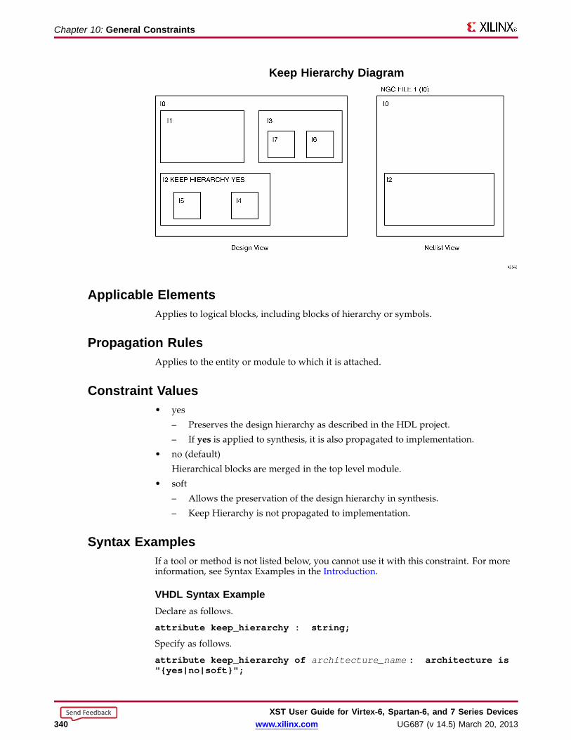
Chapter 10: General Constraints
Keep Hierar chy Diagram
Applicab le ElementsApplies to logical blocks, including blocks of hierarchy or symbols.
Propagation RulesApplies to the entity or module to which it is attached.
Constraint Values• yes
– Preserves the design hierarchy as described in the HDL project.– If yes is applied to synthesis, it is also propagated to implementation.
• no (default)Hierarchical blocks are merged in the top level module.
• soft– Allows the preservation of the design hierarchy in synthesis.– Keep Hierarchy is not propagated to implementation.
Syntax ExamplesIf a tool or method is not listed below, you cannot use it with this constraint. For moreinformation, see Syntax Examples in the Introduction.
VHDL Syntax ExampleDeclare as follows.
attribute keep_hierarchy : string;
Specify as follows.
attribute keep_hierarchy of architecture_name : architecture is"{yes|no|soft}";
XST User Guide for Vir tex-6, Spar tan-6, and 7 Series Devices340 www.xilinx.com UG687 (v 14.5) March 20, 2013
Send Feedback

Chapter 10: General Constraints
Verilog Syntax Example(* keep_hierarchy = "{yes|no|soft}" *)
XCF Syntax ExampleMODEL" entity_name " keep_hierarchy={yes|no|soft};
Command Line Syntax ExampleDefine globally with the run command.
-keep_hierarchy {yes|no|soft}
For more information, see Command Line Mode.
ISE Design Suite Syntax ExampleDefine globally in ISE® Design Suite.
Process > Properties > Synthesis Options > Keep Hierarchy
XST User Guide for Vir tex-6, Spar tan-6, and 7 Series DevicesUG687 (v 14.5) March 20, 2013 www.xilinx.com 341
Send Feedback
Chapter 10: General Constraints
Librar y Search OrderThe Library Search Order (-lso) command line option specifies the order in whichlibrary files are used.
To invoke Library Search Order:
• Specify the search order file in ISE® Design Suite.
Process > Properties > Synthesis Options > Library Search Order, or
• Use the –lso command line option.
For more information, see Library Search Order (LSO) Files.
Applicab le ElementsApplies to files.
Propagation RulesNot applicable.
Constraint ValuesThe only allowed value is a file name.
Constraint DefaultThere is no default file name. If not specified, XST uses the default search order.
Syntax ExamplesIf a tool or method is not listed below, you cannot use it with this constraint. For moreinformation, see Syntax Examples in the Introduction.
XST Command Line Syntax ExampleDefine globally with the run command.
-lso file_name .lso
ISE Design Suite Syntax ExampleDefine globally in ISE Design Suite
Process > Properties > Synthesis Options > Library Search Order
XST User Guide for Vir tex-6, Spar tan-6, and 7 Series Devices342 www.xilinx.com UG687 (v 14.5) March 20, 2013
Send Feedback

Chapter 10: General Constraints
LOCLOC defines where a design element can be placed within a device.
For more information about this constraint, see the Constraints Guide (UG625).
XST User Guide for Vir tex-6, Spar tan-6, and 7 Series DevicesUG687 (v 14.5) March 20, 2013 www.xilinx.com 343
Send Feedback

Chapter 10: General Constraints
Netlist Hierar chyThe Netlist Hierarchy (-netlist_hierarchy) command line option:• Controls the form in which the final NGC netlist is generated.• Allows you to write the hierarchical netlist even if the optimization was done on a
partially or fully-flattened design.
The hierarchy is not always fully rebuilt.
Optimization of Small Hierar chical Bloc ks During LUT Optimizations• During Low-Level Synthesis, logic optimizations such as LUT packing may send all
logic in certain small hierarchical blocks to the surrounding context.• These small hierarchical blocks:
– Are of very low complexity.– Are typically only a few LUTs.– Are eliminated during optimization.– Are not rebuilt in the final netlist.
Macro Grouping Across Hierar chy• During Advanced HDL Synthesis, XST attempts to group basic inferred macros
together into higher complexity macros.• These composite macros are usually candidates for implementation with DSP or
block RAM resources.• When grouped macros are inferred in distinct hierarchical blocks, local hierarchical
boundaries:– May be removed.– Are not rebuilt in the final netlist.
Applicab le ElementsApplies globally.
Propagation RulesNot applicable.
Constraint Values• as_optimized (default)
– XST takes Keep Hierarchy into account.– XST generates the NGC netlist in the form in which it was optimized.– Some hierarchical blocks are flattened, while others maintain hierarchy
boundaries.• rebuilt
XST writes a hierarchical NGC netlist, regardless of Keep Hierarchy.
XST User Guide for Vir tex-6, Spar tan-6, and 7 Series Devices344 www.xilinx.com UG687 (v 14.5) March 20, 2013
Send Feedback
Chapter 10: General Constraints
Syntax ExamplesIf a tool or method is not listed below, you cannot use it with this constraint. For moreinformation, see Syntax Examples in the Introduction.
XST Command Line Syntax ExampleDefine globally with the run command.
- netlist_hierarchy {as_optimized|rebuilt}
XST User Guide for Vir tex-6, Spar tan-6, and 7 Series DevicesUG687 (v 14.5) March 20, 2013 www.xilinx.com 345
Send Feedback
Chapter 10: General Constraints
Optimization Effor tThe Optimization Effort (OPT_LEVEL) constraint defines the synthesis OptimizationEffort Level.
Applicab le ElementsApplies globally, or to an entity or module.
Propagation RulesApplies to the entity or module to which it is attached.
Constraint Values• 1 (Normal Optimization Effort Level) (default)
– Is the recommended Optimization Effort Level.– Results in (especially for hierarchical designs)
♦ A high level of optimizations.♦ Fast processing times.
• 2 (High Optimization Effort Level)– Instructs XST to explore additional optimization techniques.– Can result in significantly increased synthesis runtimes.– Does not guarantee a better outcome.– May benefit only some designs. In other designs there may be no improvement,
or the results may be degraded.• 0 (Fast Optimization Effort Level)
– Turns off some of the optimization algorithms used in Optimization EffortLevel One (Normal).
– Delivers a synthesized result in minimal runtime.– May result in an optimization trade-off.– Is used early in the design process to obtain rapid results.
Syntax ExamplesIf a tool or method is not listed below, you cannot use it with this constraint. For moreinformation, see Syntax Examples in the Introduction.
VHDL Syntax ExampleDeclare as follows.
attribute opt_level: string;
Specify as follows.
attribute opt_level of entity_name: entity is "{0|1|2}";
Verilog Syntax Example(* opt_level = "{0|1|2}" *)
XCF Syntax ExampleMODEL "entity_name" opt_level={0|1|2};
XST User Guide for Vir tex-6, Spar tan-6, and 7 Series Devices346 www.xilinx.com UG687 (v 14.5) March 20, 2013
Send Feedback

Chapter 10: General Constraints
XST Command Line Syntax ExampleDefine globally with the run command.
-opt_level {0|1|2}
ISE Design Suite Syntax ExampleDefine globally in ISE® Design Suite.
Process > Properties > Synthesis Options > Optimization Effort
XST User Guide for Vir tex-6, Spar tan-6, and 7 Series DevicesUG687 (v 14.5) March 20, 2013 www.xilinx.com 347
Send Feedback
Chapter 10: General Constraints
Optimization GoalThe Optimization Goal (OPT_MODE) constraint defines the synthesis optimizationstrategy.
Applicab le ElementsApplies globally, or to an entity or module.
Propagation RulesApplies to the entity or module to which it is attached.
Constraint Values• speed (default)
Reduces the number of logic levels and therefore increases frequency.• area
Reduces the total amount of logic used for design implementation and thereforeimproves design fitting.
Syntax ExamplesIf a tool or method is not listed below, you cannot use it with this constraint. For moreinformation, see Syntax Examples in the Introduction.
VHDL Syntax ExampleDeclare as follows.
attribute opt_mode: string;
Specify as follows.
attribute opt_mode of entity_name : entity is "{speed|area}";
Verilog Syntax Example(* opt_mode = "{speed|area}" *)
XCF Syntax ExampleMODEL" entity_name " opt_mode={speed|area};
XST Command Line Syntax ExampleDefine globally with the run command.
-opt_mode {area|speed}
ISE Design Suite Syntax ExampleDefine globally in ISE® Design Suite.
Process > Properties > Synthesis Options > Optimization Goal
XST User Guide for Vir tex-6, Spar tan-6, and 7 Series Devices348 www.xilinx.com UG687 (v 14.5) March 20, 2013
Send Feedback
Chapter 10: General Constraints
Parallel CaseThe Parallel Case (PARALLEL_CASE) constraint:
• Is valid for Verilog designs only.
• Forces a case statement to be synthesized as a parallel Multiplexer.
• Prevents the case statement from being transformed into a prioritized if-elsifcascade.
Applicab le ElementsApplies to case statements in Verilog meta comments only.
Propagation RulesNot applicable.
Syntax ExamplesIf a tool or method is not listed below, you cannot use it with this constraint. For moreinformation, see Syntax Examples in the Introduction.
Verilog Syntax Example(* parallel_case *)
• Since Parallel Case does not contain a target reference, the attribute immediatelyprecedes the selector.
(* parallel_case *)casex select4’b1xxx: res = data1;4’bx1xx: res = data2;4’bxx1x: res = data3;4’bxxx1: res = data4;
endcase
• Parallel Case is also available as a meta comment in the Verilog code. The syntaxdiffers from the standard meta comment syntax as shown in the following:
// synthesis parallel_case
• Since Parallel Case does not contain a target reference, the meta commentimmediately follows the selector.
casex select // synthesis parallel_case4’b1xxx: res = data1;4’bx1xx: res = data2;4’bxx1x: res = data3;4’bxxx1: res = data4;
endcase
XST Command Line Syntax ExampleDefine globally with the run command.
-vlgcase {full|parallel|full-parallel}
XST User Guide for Vir tex-6, Spar tan-6, and 7 Series DevicesUG687 (v 14.5) March 20, 2013 www.xilinx.com 349
Send Feedback

Chapter 10: General Constraints
RLOCThe RLOC constraint:
• Is a basic mapping and placement constraint.
• Groups logic elements into discrete sets.
• Defines the location of any element within a set relative to other elements in the set,regardless of eventual placement in the overall design.
For more information about this constraint, see the Constraints Guide (UG625).
XST User Guide for Vir tex-6, Spar tan-6, and 7 Series Devices350 www.xilinx.com UG687 (v 14.5) March 20, 2013
Send Feedback

Chapter 10: General Constraints
SaveThe Save (S or SAVE) constraint is an advanced mapping constraint.
• When a design is mapped:
– Some nets are absorbed into logic blocks.
– Some elements such as LUTs are optimized away.
• SAVE prevents such optimizations in order to preserve access to specific nets andblocks in the post-synthesis netlist.
• Disabled optimization techniques include:
– Nets or blocks replication
– Register balancing
SAVE Applied To XST ActionNet Preserves the net with all elements directly connected to it in the final netlist, including
nets connected to these elements.
Block Preserves the LUT with all signals connected to it.
For more information about this constraint, see the Constraints Guide (UG625).
Applicab le Elements• Nets
XST preserves the designated net with all elements directly connected to it in thefinal netlist. Nets connected to these elements are also preserved.
• Instantiated device primitives
If SAVE is applied to an instantiated primitive such as a LUT, XST preserves the LUTwith all signals connected to it.
XST User Guide for Vir tex-6, Spar tan-6, and 7 Series DevicesUG687 (v 14.5) March 20, 2013 www.xilinx.com 351
Send Feedback
Chapter 10: General Constraints
Synthesis Constraint FileThe Synthesis Constraint File (–uc) command line option specifies the XST ConstraintFile (XCF) that XST uses during synthesis.
• The XCF has an extension of .xcf .
• If the extension is not .xcf , XST errors out and stops processing.
Applicab le ElementsApplies to files.
Propagation RulesNot applicable.
Constraint ValueThe only value is a file name. There is no default.
Syntax ExamplesIf a tool or method is not listed below, you cannot use it with this constraint. For moreinformation, see Syntax Examples in the Introduction.
XST Command Line Syntax ExampleDefine globally with the run command.
-uc filename
ISE Design Suite Syntax ExampleDefine globally in ISE® Design Suite.
Process > Properties > Synthesis Options > Synthesis Constraints File
XST User Guide for Vir tex-6, Spar tan-6, and 7 Series Devices352 www.xilinx.com UG687 (v 14.5) March 20, 2013
Send Feedback
Chapter 10: General Constraints
Translate Off and Translate OnThe Translate Off (TRANSLATE_OFF) and Translate On (TRANSLATE_ON) constraintsinstruct XST to ignore HDL source code not relevant for synthesis, such as simulationcode.
• TRANSLATE_OFF marks the beginning of the section to be ignored.
• TRANSLATE_ON marks the end of the section to be ignored.
Synopsys DirectivesTranslate Off and Translate On are Synopsys directives.
• XST supports Translate Off and Translate On in Verilog.
• Automatic conversion is also available in VHDL and Verilog.
• Translate Off and Translate On can be used with the following words:
– synthesis
– synopsys
– pragma
Applicab le ElementsApplies locally.
Propagation RulesInstructs the synthesis tool to enable or disable portions of code.
Syntax ExamplesIf a tool or method is not listed below, you cannot use it with this constraint. For moreinformation, see Syntax Examples in the Introduction.
VHDL Syntax ExampleDeclare as follows.
-- synthesis translate_off...code not synthesized...-- synthesis translate_on
Verilog Syntax ExampleTranslate Off and Translate On are available as HDL meta comments. The Verilog syntaxdiffers from the standard meta comment syntax.
// synthesis translate_off...code not synthesized...// synthesis translate_on
XST User Guide for Vir tex-6, Spar tan-6, and 7 Series DevicesUG687 (v 14.5) March 20, 2013 www.xilinx.com 353
Send Feedback
Chapter 10: General Constraints
Verilog Include Directories• The Verilog Include Directories (–vlgincdir) command line option:
– Is used in conjunction with ‘include.
– Helps the parser find files referenced by ‘include statements.
• When an ‘include statement references a file, XST searches in the following orderrelative to the:
– Current working directory
– Directory of the Verilog file containing ‘include
– Directory of the .prj file
– Directories referenced by the -vlgincdir option
Applicab le ElementsApplies to directories.
Propagation RulesNot applicable.
Constraint ValuesAllowed values are names of directories.
Syntax ExamplesIf a tool or method is not listed below, you cannot use it with this constraint. For moreinformation, see Syntax Examples in the Introduction.
XST Command Line Syntax ExampleDefine globally with the run command.
-vlgincdir { directory_path [directory_path] }
ISE Design Suite Syntax ExampleDefine globally in ISE® Design Suite.
Process > Properties > Synthesis Options > Verilog Include Directories
To view this constraint, select Edit > Preferences > Processes > Property Display Level> Advanced.
XST User Guide for Vir tex-6, Spar tan-6, and 7 Series Devices354 www.xilinx.com UG687 (v 14.5) March 20, 2013
Send Feedback

Chapter 10: General Constraints
Verilog MacrosThe Verilog Macros (-define) command line option:• Defines (or redefines) Verilog macros.• Allows you to modify the design configuration without modifying the source code.• Can be used for IP core generation and flow testing. If the defined macro is not
used in the design, no message is given.
Applicab le ElementsApplies globally.
Propagation RulesNot applicable.
Constraint Values• name is a macro name• value is a macro text
The default is an empty definition.
-define {}
Syntax Rules• Values for macros are not mandatory.• Place the values inside {braces}.• Separate the values with spaces.• You can specify macro text between quotation marks or without them. If the macro
text contains spaces, you must use quotation marks.
-define {macro1=Xilinx macro2="Xilinx Virtex6"}
• Do not use {braces} when specifying values in ISE® Design Suite.acro1=Xilinx macro2="Xilinx Virtex6"
Syntax ExamplesIf a tool or method is not listed below, you cannot use it with this constraint. For moreinformation, see Syntax Examples in the Introduction.
XST Command Line Syntax ExampleDefine globally with the run command.
-define {name[=value] name[=value] -}
ISE Design Suite Syntax ExampleDefine globally in ISE Design Suite.
Process > Properties > Synthesis Options > Verilog Macros
XST User Guide for Vir tex-6, Spar tan-6, and 7 Series DevicesUG687 (v 14.5) March 20, 2013 www.xilinx.com 355
Send Feedback

Chapter 10: General Constraints
Work Director yThe Work Directory (-xsthdpdir) command line option defines the location in whichVHDL-compiled files must be placed if the location is not defined by library mappingfiles.• ISE® Design Suite
Process > Properties > Synthesis Options > VHDL Work Directory• Command Line Mode
set -xsthdpdir directory
Work Director y Examples1. Three different users are working on the same project.2. They share one standard, pre-compiled library, shlib .3. This library contains specific macro blocks for their project.4. Each user also maintains a local work library.5. User Three places her local work library outside the project directory (for example,
in c:\temp) .6. User One and User Two share another library (lib12 ) between them, but not
with User Three.
Work Director y Example User OneMapping file:schlib=z:\sharedlibs\shliblib12=z:\userlibs\lib12
Work Director y Example User TwoMapping file:schlib=z:\sharedlibs\shliblib12=z:\userlibs\lib12
Work Director y Example User ThreeMapping file:schlib=z:\sharedlibs\shlib
User Three also sets:
XSTHDPDIR = c:\temp
Applicab le ElementsApplies to directories.
Propagation RulesNot applicable.
Constraint ValuesAllowed values are names of directories.
XST User Guide for Vir tex-6, Spar tan-6, and 7 Series Devices356 www.xilinx.com UG687 (v 14.5) March 20, 2013
Send Feedback
Chapter 10: General Constraints
Syntax ExamplesIf a tool or method is not listed below, you cannot use it with this constraint. For moreinformation, see Syntax Examples in the Introduction.
XST Command Line Syntax ExampleDefine globally with the run command.
set -xsthdpdir directory
Work Directory can accept a single path only. You must specify the directory.
ISE Design Suite Syntax ExampleDefine globally in ISE Design Suite.
Process > Properties > Synthesis Options > VHDL Work Directory
To view this constraint, select Edit > Preferences > Processes > Property Display Level> Advanced.
XST User Guide for Vir tex-6, Spar tan-6, and 7 Series DevicesUG687 (v 14.5) March 20, 2013 www.xilinx.com 357
Send Feedback

XST User Guide for Vir tex-6, Spar tan-6, and 7 Series Devices358 www.xilinx.com UG687 (v 14.5) March 20, 2013
Send Feedback
Chapter 11
HDL ConstraintsThis chapter discusses XST Hardware Description Language (HDL) constraints.
For most constraints, this chapter gives the following information:
• Constraint Description
• Applicable Elements
• Propagation Rules
• Constraint Values
• Syntax Examples
XST User Guide for Vir tex-6, Spar tan-6, and 7 Series DevicesUG687 (v 14.5) March 20, 2013 www.xilinx.com 359
Send Feedback

Chapter 11: HDL Constraints
Automatic FSM ExtractionThe Automatic FSM Extraction (FSM_EXTRACT) constraint:• Enables Finite State Machine (FSM) extraction and specific synthesis optimizations.• Must be enabled in order to set values for the FSM Encoding Algorithm and FSM
Flip-Flop Type.
Applicab le ElementsApplies globally, or to an entity, module, or signal.
Propagation RulesApplies to the entity, module, or signal to which it is attached.
Constraint Values• yes [or true (XCF)] (default)• no [or false (XCF)]
Syntax ExamplesIf a tool or method is not listed below, you cannot use it with this constraint. For moreinformation, see Syntax Examples in the Introduction.
VHDL Syntax ExampleDeclare as follows.
attribute fsm_extract: string;
Specify as follows.
attribute fsm_extract of { entity_name | signal_name }:{entity|signal is "{yes|no}";
Verilog Syntax ExamplePlace immediately before the module or signal declaration.
(* fsm_extract = "{yes|no}" *)
XCF Syntax Example OneMODEL" entity_name " fsm_extract={yes|no|true|false};
XCF Syntax Example TwoBEGIN MODEL" entity_name "
NET " signal_name " fsm_extract={yes|no|true|false};
END;
XST Command Line Syntax ExampleDefine globally with the run command.
-fsm_extract {yes|no}*
XST User Guide for Vir tex-6, Spar tan-6, and 7 Series Devices360 www.xilinx.com UG687 (v 14.5) March 20, 2013
Send Feedback

Chapter 11: HDL Constraints
ISE Design Suite Syntax ExampleDefine globally in ISE® Design Suite.
Process > Properties > HDL Options > FSM Encoding Algorithm
• If FSM Encoding Algorithm is set to none, and -fsm_extract is set to no,-fsm_encoding does not influence synthesis.
• In all other cases, -fsm_extract is set to yes, and -fsm_encoding is set to the selectedvalue. .
XST User Guide for Vir tex-6, Spar tan-6, and 7 Series DevicesUG687 (v 14.5) March 20, 2013 www.xilinx.com 361
Send Feedback

Chapter 11: HDL Constraints
Enumerated EncodingThe Enumerated Encoding (ENUM_ENCODING) constraint:
• Applies a specific encoding to a VHDL enumerated type.
• Can be specified only as a VHDL constraint on the enumerated type.
• Allows you to specify the encoding scheme for a Finite State Machine (FSM) thatuses an enumerated type for the state register.
• Must have FSM Encoding Algorithm set to user for the state register.
Applicab le Elements• Applies to a type or signal.
• Because Enumerated Encoding must preserve the external design interface, XSTignores Enumerated Encoding when it is used on a port.
Propagation RulesApplies to the type or signal to which it is attached.
Constraint ValuesThe value is a string containing space-separated binary codes.
Syntax ExamplesIf a tool or method is not listed below, you cannot use it with this constraint. For moreinformation, see Syntax Examples in the Introduction.
VHDL Syntax ExampleSpecify as a VHDL constraint on the considered enumerated type.
...architecture behavior of example istype statetype is (ST0, ST1, ST2, ST3);attribute enum_encoding : string;attribute enum_encoding of statetype : type is "001 010 100 111";signal state1 : statetype;signal state2 : statetype;begin...
XCF Syntax ExampleBEGIN MODEL" entity_name "
NET " signal_name " enum_encoding=" string ";
END;
XST User Guide for Vir tex-6, Spar tan-6, and 7 Series Devices362 www.xilinx.com UG687 (v 14.5) March 20, 2013
Send Feedback

Chapter 11: HDL Constraints
Equiv alent Register RemovalThe Equivalent Register Removal (EQUIVALENT_REGISTER_REMOVAL) constraintenables or disables removal of equivalent Registers described at the Register TransferLevel (RTL).
• XST does not remove equivalent Flip-Flops if they are instantiated from a Xilinx®primitive library.
• Removing equivalent Flip-Flops increases the probability that the design will fiton the device
Applicab le ElementsApplies globally, or to an entity, module, or signal.
Propagation RulesRemoves equivalent flip-flops and flip-flops with constant inputs.
Constraint Values• yes [or true (XCF)] (default)
Flip-Flop optimization is allowed.
• no [or false (XCF)]
Flip-Flop optimization is inhibited.
Flip-Flop optimization is time consuming. For fast processing, use no.
Syntax ExamplesIf a tool or method is not listed below, you cannot use it with this constraint. For moreinformation, see Syntax Examples in the Introduction.
VHDL Syntax ExampleDeclare as follows.
attribute equivalent_register_removal: string;
Specify as follows.
attribute equivalent_register_removal of{ entity_name | signal_name }: {signal|entity} is "{yes|no}";
Verilog Syntax ExamplePlace immediately before the module or signal declaration.
(* equivalent_register_removal = "{yes|no}" *)
XCF Syntax Example OneMODEL" entity_name "equivalent_register_removal={yes|no|true|false};
XST User Guide for Vir tex-6, Spar tan-6, and 7 Series DevicesUG687 (v 14.5) March 20, 2013 www.xilinx.com 363
Send Feedback

Chapter 11: HDL Constraints
XCF Syntax Example TwoBEGIN MODEL" entity_name "
NET " signal_name "equivalent_register_removal={yes|no|true|false};
END;
XST Command Line Syntax ExampleDefine globally with the run command.
-equivalent_register_removal {yes|no}
ISE Design Suite Syntax ExampleDefine globally in ISE® Design Suite.
Process > Properties > Xilinx-Specific Options > Equivalent Register Removal
XST User Guide for Vir tex-6, Spar tan-6, and 7 Series Devices364 www.xilinx.com UG687 (v 14.5) March 20, 2013
Send Feedback

Chapter 11: HDL Constraints
FSM Encoding Algorithm• The FSM Encoding Algorithm (FSM_ENCODING) constraint selects the Finite State
Machine (FSM) coding technique.
• Automatic FSM Extraction must be enabled in order to select a value for the FSMEncoding Algorithm.
Applicab le ElementsApplies globally, or to an entity, module, or signal.
Propagation RulesApplies to the entity, module, or signal to which it is attached.
Constraint Values• auto (default)
XST selects the best coding technique for each individual state machine.
• one-hot
• compact
• sequential
• gray
• johnson
• speed1
• user
Syntax ExamplesIf a tool or method is not listed below, you cannot use it with this constraint. For moreinformation, see Syntax Examples in the Introduction.
VHDL Syntax ExampleDeclare as follows.
attribute fsm_encoding: string;
Specify as follows.
attribute fsm_encoding of{ entity_name|signal_name }: {entity|signal} is"{auto|one-hot|compact|sequential|gray|johnson|speed1|user}";
XST User Guide for Vir tex-6, Spar tan-6, and 7 Series DevicesUG687 (v 14.5) March 20, 2013 www.xilinx.com 365
Send Feedback

Chapter 11: HDL Constraints
Verilog Syntax ExamplePlace immediately before the module or signal declaration.
(* fsm_encoding = "{auto|one-hot|compact|sequential|gray|johnson|speed1|user}" *)
XCF Syntax Example OneMODEL" entity_name " fsm_encoding={auto|one-hot|compact|sequential|gray|johnson|speed1|user};
XCF Syntax Example TwoBEGIN MODEL" entity_name "
NET " signal_name " fsm_encoding={auto|one-hot|compact|sequential|gray|johnson|speed1|user};
END;
XST Command Line Syntax ExampleDefine globally with the run command.
-fsm_encoding{auto|one-hot|compact|sequential|gray|johnson|speed1|user}
ISE Design Suite Syntax ExampleDefine globally in ISE® Design Suite.
Process > Properties > HDL Options > FSM Encoding Algorithm
• If FSM Encoding Algorithm is set to none, and -fsm_extract is set to no,-fsm_encoding has no influence on the synthesis.
• In all other cases, -fsm_extract is set to yes and -fsm_encoding is set to the valueselected in the menu.
For more information, see Automatic FSM Extraction.
XST User Guide for Vir tex-6, Spar tan-6, and 7 Series Devices366 www.xilinx.com UG687 (v 14.5) March 20, 2013
Send Feedback
Chapter 11: HDL Constraints
Mux Minimal SizeCaution! Review this constraint carefully before use.
The Mux Minimal Size (MUX_MIN_SIZE) constraint:
• Controls the minimal size of Multiplexer macros inferred by XST.
• Takes an integer value greater than 1. The default is 2.
Number of Multiple xed Data InputsSize is the number of multiplexed data inputs. Selector inputs do not count.
Multiple xer Size2-to-1 Multiplexer 2
16-to-1 Multiplexer 16
Width of Selected DataSize is independent of the width of the selected data.
Multiple xer Size1-bit wide 8-to-1 Multiplexer 8
16-bit wide 8-to-1 Multiplexer 8
2-to-1 Multiple xer MacrosXST automatically infers 2-to-1 Multiplexer macros.
• Explicitly inferring 2-to-1 Multiplexers can positively or negatively impact deviceutilization.
– If device utilization is satisfactory, do not use Mux Minimal Size.
– If device utilization is not satisfactory, Mux Minimal Size may benefit yourdesign.
Note A large number of inferred 2-to-1 Multiplexers may be contributing to theunsatisfactory device utilization. Apply a value of 3 to disable inferencing of2-to-1 Multiplexers, either globally or for the specific blocks that are contributingto the unsatisfactory device utilization.
• Mux Minimal Size may prevent inferencing of Multiplexers for sizes above 2, butthe benefits are speculative. Use extra caution before applying Mux Minimal Sizefor sizes above 2.
Applicab le ElementsApplies globally, or to a designated VHDL entity or Verilog module.
Propagation RulesApplies to the designated entity or module.
XST User Guide for Vir tex-6, Spar tan-6, and 7 Series DevicesUG687 (v 14.5) March 20, 2013 www.xilinx.com 367
Send Feedback

Chapter 11: HDL Constraints
Syntax ExamplesIf a tool or method is not listed below, you cannot use it with this constraint. For moreinformation, see Syntax Examples in the Introduction.
VHDL Syntax ExampleDeclare as follows.
attribute mux_min_size: string;
Specify as follows.
attribute mux_min_size of entity_name : entity is " integer ";
Verilog Syntax ExamplePlace immediately before the module declaration
(* mux_min_size= " integer " *)
XST Command Line Syntax ExampleDefine globally with the run command.
-mux_min_size integer
Mux Minimal Size is not available in the default XST options set in ISE® Design Suite.
XST User Guide for Vir tex-6, Spar tan-6, and 7 Series Devices368 www.xilinx.com UG687 (v 14.5) March 20, 2013
Send Feedback
Chapter 11: HDL Constraints
Resour ce SharingThe Resource Sharing (RESOURCE_SHARING) constraint enables or disables resourcesharing of arithmetic operators.
Applicab le ElementsApplies globally, or to design elements.
Propagation RulesApplies to the entity or module to which it is attached.
Constraint Values• yes [or true (XCF)] (default)
• no [or false (XCF)]
Syntax ExamplesIf a tool or method is not listed below, you cannot use it with this constraint. For moreinformation, see Syntax Examples in the Introduction.
VHDL Syntax ExampleDeclare as follows.
attribute resource_sharing: string;
Specify as follows.
attribute resource_sharing of entity_name : entity is"{yes|no}";
Verilog Syntax ExamplePlace immediately before the module declaration or instantiation.
attribute resource_sharing of entity_name : entity is"{yes|no}";
XCF Syntax Example OneMODEL" entity_name " resource_sharing={yes|no|true|false};
XCF Syntax Example TwoBEGIN MODEL" entity_name "
NET " signal_name " resource_sharing={yes|no|true|false};
END;
XST User Guide for Vir tex-6, Spar tan-6, and 7 Series DevicesUG687 (v 14.5) March 20, 2013 www.xilinx.com 369
Send Feedback
Chapter 11: HDL Constraints
XST Command Line Syntax ExampleDefine globally with the run command.
-resource_sharing {yes|no}
ISE Design Suite Syntax ExampleDefine globally in ISE® Design Suite.
HDL Options > Resource Sharing
XST User Guide for Vir tex-6, Spar tan-6, and 7 Series Devices370 www.xilinx.com UG687 (v 14.5) March 20, 2013
Send Feedback

Chapter 11: HDL Constraints
Safe ImplementationThe Safe Implementation (SAFE_IMPLEMENTATION) constraint implements FiniteState Machine (FSM) components in Safe Implementation mode.• If the FSM enters an invalid state, XST generates additional logic that forces the FSM
to a valid state (recovery state).– XST selects reset as the default recovery state.– If the FSM does not have an initialization signal, XST selects power-up as the
recovery state.– Define the recovery state manually with Safe Recovery State.
• Activate Safe Implementation as follows:– ISE® Design Suite
Process > Properties > HDL Options > Safe Implementation– Hardware Description Language (HDL)
Apply Safe Implementation to the hierarchical block or signal that representsthe state register in the FSM.
Applicab le ElementsApplies to an entire design through the XST command line, to a particular block (entity,architecture, component), or to a signal.
Propagation RulesApplies to an entity, component, module, signal, or instance to which it is attached.
Constraint Values• yes [or true (XCF)]• no [or false (XCF)] (default)
Syntax ExamplesIf a tool or method is not listed below, you cannot use it with this constraint. For moreinformation, see Syntax Examples in the Introduction.
VHDL Syntax ExampleDeclare as follows.
attribute safe_implementation: string;
Specify as follows.
attribute safe_implementation ofentity_ name|component_ name|signal_ name}:entity|component|signalis "{yes|no}}";
Verilog Syntax ExamplePlace immediately before the module or signal declaration.
(* safe_implementation = "{yes|no}" *)
XCF Syntax Example OneMODEL" entity_name " safe_implementation={yes|no|true|false};
XST User Guide for Vir tex-6, Spar tan-6, and 7 Series DevicesUG687 (v 14.5) March 20, 2013 www.xilinx.com 371
Send Feedback

Chapter 11: HDL Constraints
XCF Syntax Example TwoBEGIN MODEL" entity_name "
NET " signal_name "safe_implementation="{yes|no|true|false};
END;
XST Command Line Syntax ExampleDefine globally with the run command.
-safe_implementation {yes|no}
ISE Design Suite Syntax ExampleDefine globally in ISE Design Suite.
HDL Options > Safe Implementation
XST User Guide for Vir tex-6, Spar tan-6, and 7 Series Devices372 www.xilinx.com UG687 (v 14.5) March 20, 2013
Send Feedback
Chapter 11: HDL Constraints
Safe Recovery StateThe Safe Recovery State (SAFE_RECOVERY_STATE) constraint defines a recovery statefor use when a Finite State Machine (FSM) is implemented in Safe Implementation mode.
• If the FSM enters an invalid state, XST uses additional logic to force the FSM toa valid recovery state.
• By implementing FSM in safe mode, XST collects all code not participating in thenormal FSM behavior and treats it as illegal.
• XST uses logic that returns the FSM synchronously to the:
– Known state
– Reset state
– Power up state
– State specified using Safe Recovery State
Applicab le ElementsApplies to a signal representing a state register
Propagation RulesApplies to the signal to which it is attached.
Syntax ExamplesIf a tool or method is not listed below, you cannot use it with this constraint. For moreinformation, see Syntax Examples in the Introduction.
VHDL Syntax ExampleDeclare as follows.
attribute safe_recovery_state: string;
Specify as follows.
attribute safe_recovery_state of { signal_name }:{signal} is"< value >";
Verilog Syntax ExamplePlace immediately before the signal declaration.
(* safe_recovery_state = "< value >" *)*
XCF Syntax ExampleBEGIN MODEL" entity_name "
NET " signal_name " safe_recovery_state="< value >";
END;
XST User Guide for Vir tex-6, Spar tan-6, and 7 Series DevicesUG687 (v 14.5) March 20, 2013 www.xilinx.com 373
Send Feedback

XST User Guide for Vir tex-6, Spar tan-6, and 7 Series Devices374 www.xilinx.com UG687 (v 14.5) March 20, 2013
Send Feedback

Chapter 12
FPGA Constraints (Non-Timing)This chapter discusses FPGA Constraints (Non-Timing).
For most constraints, this chapter gives the following information:
• Constraint Description
• Applicable Elements
• Propagation Rules
• Constraint Values
• Syntax Examples
Many constraints can be applied:
• Globally to an entire entity or model, or
• Locally to individual signals, nets or instances.
XST User Guide for Vir tex-6, Spar tan-6, and 7 Series DevicesUG687 (v 14.5) March 20, 2013 www.xilinx.com 375
Send Feedback
Chapter 12: FPGA Constraints (Non-Timing)
Async hronous to SynchronousCaution! Carefully review this constraint to assess the potential impact ofAsynchronous to Synchronous transformation on your design.
Use the Asynchronous to Synchronous (ASYNC_TO_SYNC) constraint to treatasynchronous set and reset signals as synchronous.
Async hronous to Synchronous Transf ormationThe Asynchronous to Synchronous transformation:• Applies to inferred sequential elements only.• Does not apply to instantiated Flip-Flops and Latches.• Is performed on the fly.• Is reflected in the post-synthesis netlist.• Does not change the HDL source code.
Set and Reset Functionality• The set and reset functionality of Xilinx® device resources such as DSP blocks and
block RAM components is inherently synchronous.• If your coding guidelines require you to describe set and reset signals
asynchronously, you may not be using those resources to their full potential.• Asynchronous to Synchronous transformation allows you to assess the potential
of those resources without changing the description of the sequential elements inthe HDL source code.
• By better leveraging Registers, you may be able to:– Improve device utilization– Increase circuit performance– Achieve better power reduction
Post-Synthesis Netlist• As a result of Asynchronous to Synchronous transformation, the post-synthesis
netlist is theoretically not functionally equivalent to the pre-synthesis HDLdescription.
• However, the post-synthesis netlist is functionally equivalent if:– The transformation does not actually use the asynchronous sets and resets that
you have described, or– The asynchronous sets and resets are derived from synchronous sources.
Changing the HDL DescriptionIf you achieve your design goals by using Asynchronous to Synchronous transformation,determine whether you should change the HDL description to:• Enforce synchronous set and reset signals in order to ensure the expected circuit
behavior.• Ease design validation.
XST User Guide for Vir tex-6, Spar tan-6, and 7 Series Devices376 www.xilinx.com UG687 (v 14.5) March 20, 2013
Send Feedback

Chapter 12: FPGA Constraints (Non-Timing)
Xilinx RecommendationsXilinx recommends that you:
• Perform a timing simulation in order to assess the impact of the Asynchronous toSynchronous transformation on your design.
• Describe synchronous set and reset signals in your HDL source code.
Applicab le ElementsApplies globally.
Propagation RulesNot applicable.
Constraint Values• yes
• no (default)
Syntax ExamplesIf a tool or method is not listed below, you cannot use it with this constraint. For moreinformation, see Syntax Examples in the Introduction.
XST Command Line Syntax ExampleDefine globally with the run command.
-async_to_sync {yes|no}
ISE Design Suite Syntax ExampleDefine globally in ISE® Design Suite.
Process > Properties > HDL Options > Asynchronous to Synchronous
XST User Guide for Vir tex-6, Spar tan-6, and 7 Series DevicesUG687 (v 14.5) March 20, 2013 www.xilinx.com 377
Send Feedback
Chapter 12: FPGA Constraints (Non-Timing)
Automatic BRAM PackingThe Automatic BRAM Packing (AUTO_BRAM_PACKING) constraint packs two smallblock RAM components into a single block RAM primitive as dual-port block RAM.
• XST packs block RAM components together only if they are situated in the samehierarchical level.
• Automatic BRAM Packing is disabled by default.
Applicab le ElementsApplies globally.
Propagation RulesNot applicable.
Constraint Values• yes
• no (default)
Syntax ExamplesIf a tool or method is not listed below, you cannot use it with this constraint. For moreinformation, see Syntax Examples in the Introduction.
XST Command Line Syntax ExampleDefine globally with the run command.
-auto_bram_packing {yes|no}
ISE Design Suite Syntax ExampleDefine globally in ISE® Design Suite.
Process > Properties > Automatic BRAM Packing
XST User Guide for Vir tex-6, Spar tan-6, and 7 Series Devices378 www.xilinx.com UG687 (v 14.5) March 20, 2013
Send Feedback

Chapter 12: FPGA Constraints (Non-Timing)
BRAM Read-Fir st ImplementationThe BRAM Read-First Implementation (RDADDR_COLLISION_HWCONFIG)constraint controls implementation of a block RAM described with read-firstsynchronization.
BRAM Read-First Implementation:• Applies to Virtex®-6 devices only.• Is ignored if:
– You are targeting a device family other than Virtex-6 devices, or– The described read-write synchronization is not read-first.
• Can be applied to:– An instantiated block RAM primitive– An inferred RAM
• Does not instruct XST in the case of inferred RAM that the described memory has aread-first synchronization. This is done by proper HDL coding.
• Is not available as an option in:– ISE® Design Suite– Command Line Mode
For more information, see Block RAM Read/Write Synchronization.
Applicab le Elements• Applies locally through:
– A VHDL attribute– A Verilog attribute– An XST Constraint File (XCF) constraint
• Applies to:– A block:
♦ Entity♦ Architecture♦ Component
– A signal describing the RAM
Propagation RulesApplies to the entity, component, module, or signal to which it is attached.
Constraint Values• delayed_write
The block RAM is configured to avoid memory collision. While conflicts areavoided, this configuration sacrifices some performance compared to write-firstand no-change synchronization.
• performanceMaximizes performance of the read-firstmode. Performance is comparable to thatobtained with write-first and no-change modes. However, you must ensure thatmemory collisions do not occur.
XST User Guide for Vir tex-6, Spar tan-6, and 7 Series DevicesUG687 (v 14.5) March 20, 2013 www.xilinx.com 379
Send Feedback
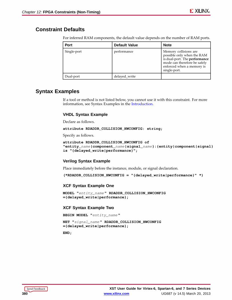
Chapter 12: FPGA Constraints (Non-Timing)
Constraint DefaultsFor inferred RAM components, the default value depends on the number of RAM ports.
Por t Default Value NoteSingle-port performance Memory collisions are
possible only when the RAMis dual-port. The performancemode can therefore be safelyenforced when a memory issingle-port.
Dual-port delayed_write
Syntax ExamplesIf a tool or method is not listed below, you cannot use it with this constraint. For moreinformation, see Syntax Examples in the Introduction.
VHDL Syntax ExampleDeclare as follows.
attribute RDADDR_COLLISION_HWCONFIG:string;
Specify as follows.
attribute RDADDR_COLLISION_HWCONFIGof"entity_ name|component_ name|signal_ name}:{entity|component|signal}is "{delayed_write|performance}";
Verilog Syntax ExamplePlace immediately before the instance, module, or signal declaration.
(*RDADDR_COLLISION_HWCONFIG= "{delayed_write|performance}" *)
XCF Syntax Example OneMODEL" entity_name " RDADDR_COLLISION_HWCONFIG={delayed_write|performance};
XCF Syntax Example TwoBEGIN MODEL" entity_name "
NET " signal_name " RDADDR_COLLISION_HWCONFIG={delayed_write|performance};
END;
XST User Guide for Vir tex-6, Spar tan-6, and 7 Series Devices380 www.xilinx.com UG687 (v 14.5) March 20, 2013
Send Feedback

Chapter 12: FPGA Constraints (Non-Timing)
BRAM Utilization RatioThe BRAM Utilization Ratio (BRAM_UTILIZATION_RATIO) constraint defines thenumber of block RAM components that XST must not exceed during synthesis.
• Block RAM components may come from:
– Block RAM inference processes
– Instantiation and block RAM mapping optimizations
• You can isolate a Register Transfer Level (RTL) description of logic in a separateblock, and then direct XST to map this logic to block RAM.
For more information, see Mapping Logic to Block RAM.
• Instantiated block RAM components are the primary candidates for available blockRAM resources.
– The inferred RAM components are placed on the remaining block RAMresources.
– If the number of instantiated block RAMs exceeds the number of availableresources, XST does not modify the instantiations and implement them as blockRAM components.
– The same behavior occurs if you force specific RAMs to be implemented asblock RAM components.
– If there are no resources, XST respects user constraints, even if the numberof block RAM resources is exceeded.
• If the number of user-specified block RAM components exceeds the number ofavailable block RAM resources on the device:
– XST issues a warning.
– XST uses only available block RAM resources for synthesis.
• Use value -1 to disable automatic block RAM resource management. This allows youto see the number of block RAM components that XST can infer for a specific design.
• Synthesis time may increase if the number of block RAM components significantlyexceeds the number of block RAM available on the device (hundreds of block RAMcomponents). This may happen due to a significant increase in design complexitywhen all non-fittable block RAM components are converted to distributed RAMcomponents.
Applicab le ElementsApplies globally.
Propagation RulesNot applicable.
XST User Guide for Vir tex-6, Spar tan-6, and 7 Series DevicesUG687 (v 14.5) March 20, 2013 www.xilinx.com 381
Send Feedback
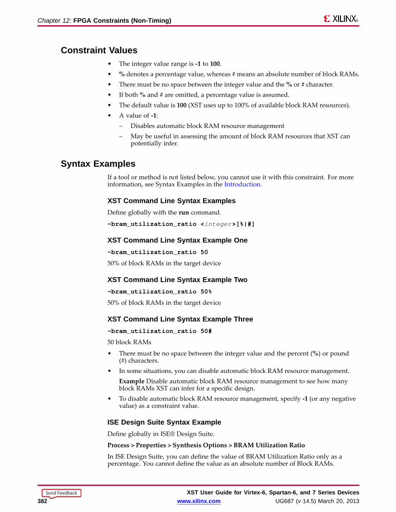
Chapter 12: FPGA Constraints (Non-Timing)
Constraint Values• The integer value range is -1 to 100.• % denotes a percentage value, whereas #means an absolute number of block RAMs.• There must be no space between the integer value and the% or # character.• If both% and # are omitted, a percentage value is assumed.• The default value is 100 (XST uses up to 100% of available block RAM resources).• A value of -1:
– Disables automatic block RAM resource management– May be useful in assessing the amount of block RAM resources that XST can
potentially infer.
Syntax ExamplesIf a tool or method is not listed below, you cannot use it with this constraint. For moreinformation, see Syntax Examples in the Introduction.
XST Command Line Syntax ExamplesDefine globally with the run command.
-bram_utilization_ratio <integer >[%|#]
XST Command Line Syntax Example One-bram_utilization_ratio 50
50% of block RAMs in the target device
XST Command Line Syntax Example Two-bram_utilization_ratio 50%
50% of block RAMs in the target device
XST Command Line Syntax Example Three-bram_utilization_ratio 50#
50 block RAMs
• There must be no space between the integer value and the percent (%) or pound(#) characters.
• In some situations, you can disable automatic block RAM resource management.Example Disable automatic block RAM resource management to see how manyblock RAMs XST can infer for a specific design.
• To disable automatic block RAM resource management, specify -1 (or any negativevalue) as a constraint value.
ISE Design Suite Syntax ExampleDefine globally in ISE® Design Suite.
Process > Properties > Synthesis Options > BRAM Utilization Ratio
In ISE Design Suite, you can define the value of BRAM Utilization Ratio only as apercentage. You cannot define the value as an absolute number of Block RAMs.
XST User Guide for Vir tex-6, Spar tan-6, and 7 Series Devices382 www.xilinx.com UG687 (v 14.5) March 20, 2013
Send Feedback

Chapter 12: FPGA Constraints (Non-Timing)
Buff er TypeThe Buffer Type (BUFFER_TYPE) constraint specifies the type of buffer to be insertedon a designated I/O port or internal net.
Applicab le ElementsApplies to signals.
Propagation RulesApplies to the signal to which it is attached.
Constraint Values• ibufg• bufg• bufgp• bufh• bufr• bufio• ibuf• obuf• buf• none
Syntax ExamplesIf a tool or method is not listed below, you cannot use it with this constraint. For moreinformation, see Syntax Examples in the Introduction.
VHDL Syntax ExampleDeclare as follows.
attribute buffer_type: string;
Specify as follows.
attribute buffer_type of signal_ name: signal is"{ibufg|bufg|bufgp|bufh|bufr|bufio|ibuf|obuf|buf|none}";
Verilog Syntax ExamplePlace immediately before the signal declaration.
(* buffer_type = "{ibufg|bufg|bufgp|bufh|bufr|bufio|ibuf|obuf|buf|none}" *)
XCF Syntax ExampleBEGIN MODEL" entity_name "
NET " signal_name " buffer_type={ibufg|bufg|bufgp|bufh|bufr|bufio|ibuf|obuf|buf|none};
END;
XST User Guide for Vir tex-6, Spar tan-6, and 7 Series DevicesUG687 (v 14.5) March 20, 2013 www.xilinx.com 383
Send Feedback

Chapter 12: FPGA Constraints (Non-Timing)
Conver t Tristates to LogicSome devices do not support internal tristates. XST replaces the internal tristates of thosedevices with equivalent logic using the Convert Tristates to Logic (TRISTATE2LOGIC)constraint.
• The equivalent logic can be combined and optimized with surrounding logic.
• Replacing internal tristates with equivalent logic can sometimes:
– Increase speed.
– Improve area optimization.
• Replacing internal tristates with equivalent logic generally increases area. If youroptimization goal is area, set Convert Tristates to Logic to no.
Conver t Tristates to Logic Limitations• Only internal tristates are replaced with equivalent logic. The tristates of the top
module connected to output pads are preserved.
• Internal tristates are not replaced with equivalent logic for modules in whichincremental synthesis is active.
• XST cannot replace an internal tristate with equivalent logic when:
– The tristate is connected to:
♦ A black box
♦ The output of a block when the hierarchy of the block is preserved
♦ A top-level output
– Convert Tristates to Logic is set to no on:
♦ The block in which the tristate is placed, or
♦ The signals to which the tristate is connected
Applicab le ElementsApplies to an entire design through the XST command line, to a particular block (entity,architecture, component), or to a signal.
Propagation RulesApplies to an entity, component, module, signal, or instance to which it is attached.
Constraint Values• yes [or true (XCF)] (default)
• no [or false (XCF)]
XST User Guide for Vir tex-6, Spar tan-6, and 7 Series Devices384 www.xilinx.com UG687 (v 14.5) March 20, 2013
Send Feedback

Chapter 12: FPGA Constraints (Non-Timing)
Syntax ExamplesIf a tool or method is not listed below, you cannot use it with this constraint. For moreinformation, see Syntax Examples in the Introduction.
VHDL Syntax ExampleDeclare as follows.
attribute tristate2logic: string;
Specify as follows.
attribute tristate2logic of{entity_ name|component_ name|signal_ name}:{entity|component|signal} is "{yes|no}";
Verilog Syntax ExamplePlace immediately before the module or signal declaration.
(* tristate2logic = "{yes|no}" *)
XCF Syntax Example OneMODEL" entity_name " tristate2logic={yes|no|true|false};
XCF Syntax Example TwoBEGIN MODEL" entity_name "
NET " signal_name " tristate2logic={yes|no|true|false};
END;
XST Command Line Syntax ExampleDefine globally with the run command.
-tristate2logic {yes|no}
ISE Design Suite Syntax ExampleDefine globally in ISE® Design Suite.
Process > Properties > Xilinx-Specific Options > Convert Tristates to Logic
XST User Guide for Vir tex-6, Spar tan-6, and 7 Series DevicesUG687 (v 14.5) March 20, 2013 www.xilinx.com 385
Send Feedback

Chapter 12: FPGA Constraints (Non-Timing)
Cores Search DirectoriesThe Cores Search Directories (–sd) command line option specifies the directories (inaddition to the default directory) in which XST looks for cores.
• XST searches for cores by default in the directory designated by the -ifn option.
• List only the directories containing the cores. Do not list individual core files.
• Specify core directories with absolute or relative paths.
Applicab le ElementsApplies globally.
Propagation RulesNot applicable.
Constraint Values• The value may be a single directory name, or a list of several directory names.
– Enclose the list of directory names between {braces}.
– Omit the {braces} if specifying only one directory.
– Separate multiple directory names with spaces.
• Xilinx® recommends that you not use directory names containing spaces.
– You may include directory names containing spaces in your search list if theyare enclosed in double quotes.
-sd {"./mydir1/mysubdir1" "./mydir2" "./mydir3/mysubdirwith space" }
– For more information, see Names With Spaces in Command Line Mode.
Syntax ExamplesIf a tool or method is not listed below, you cannot use it with this constraint. For moreinformation, see Syntax Examples in the Introduction.
XST Command Line Syntax ExampleDefine globally with the run command.
-sd {directory_path [ directory_path ]}
ISE Design Suite Syntax ExampleDefine globally in ISE® Design Suite.
Process > Properties > Synthesis Options > Cores Search Directory
XST User Guide for Vir tex-6, Spar tan-6, and 7 Series Devices386 www.xilinx.com UG687 (v 14.5) March 20, 2013
Send Feedback

Chapter 12: FPGA Constraints (Non-Timing)
DSP Utilization RatioThe DSP Utilization Ratio (DSP_UTILIZATION_RATIO) constraint restricts the numberof DSP blocks that XST uses to implement inferred functions.
• XST infers DSP blocks within the limit of available resources.
• DSP Utilization Ratio prevents XST from using all those resources.
Budg eting DSP Resour ces• Designers typically use DSP Utilization Ratio in a collaborative workflow.
– Components are designed separately before being consolidated into the finalproject.
– DSP Utilization Ratio allows you to budget DSP resources for each separatecomponent.
• DSP Utilization Ratio defines either:
– An absolute number of DSP slices, or
– A percentage of the total amount of resources available on the device.
• The default is 100% of DSP resources available in the selected device.
• XST flags any absolute number or percentage that exceeds available DSP resources.XST uses no more resources than allowed by the device.
• Instantiated DSP primitives are served first. XST allocates a corresponding amountfrom the total budget defined by DSP Utilization Ratio. XST uses the remainingresources to implement inferred functions.
• The defined budget may be exceeded if:
– The number of instantiated DSP blocks is higher than the defined budget.All DSP instantiations are always honored by XST. You must ensure that theselected device can accommodate all instantiated DSP blocks.
– You have forced DSP implementation of inferred macros with Use DSP Blockset to yes.
• When using Use DSP Block set to yes, XST ignores both the maximumDSP allocationdefined by DSP Utilization Ratio, and the amount of DSP resource actually availablein the selected device. Your design may not fit in the device as a result. DSPUtilization Ratio works best with the auto and automaxmodes of Use DSP Block.
Disab ling Automatic DSP Resour ce ManagementTo disable automatic DSP resource management, set DSP Utilization Ratio to -1 (or anynegative value). For example, you might disable automatic DSP resource managementto see how many DSP components XST can infer for a specific design.
Applicab le ElementsApplies globally.
Propagation RulesNot applicable.
XST User Guide for Vir tex-6, Spar tan-6, and 7 Series DevicesUG687 (v 14.5) March 20, 2013 www.xilinx.com 387
Send Feedback

Chapter 12: FPGA Constraints (Non-Timing)
Constraint Values• <integer> range is [-1 to 100] when% is used or both% and # are omitted.
• To specify a percent of total slices:
– -dsp_utilization_ratio 50
OR
– -dsp_utilization_ratio 50%
• To specify an absolute number of slices:
-dsp_utilization_ratio 50#
• There must be no space between the integer value and the percent (%) or pound(#) characters.
• The default is %.
Syntax ExamplesIf a tool or method is not listed below, you cannot use it with this constraint. For moreinformation, see Syntax Examples in the Introduction.
XST Command Line Syntax ExampleDefine globally with the run command.
-dsp_utilization_ratio number[%|#]
ISE Design Suite Syntax ExampleDefine globally in ISE® Design Suite.
Process > Properties > Synthesis Options > DSP Utilization Ratio
In ISE Design Suite, you can define the value of DSP Utilization Ratio only as a percent.You cannot define the value as an absolute number of slices.
XST User Guide for Vir tex-6, Spar tan-6, and 7 Series Devices388 www.xilinx.com UG687 (v 14.5) March 20, 2013
Send Feedback
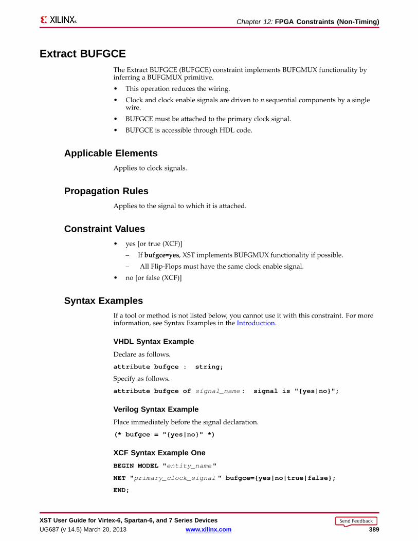
Chapter 12: FPGA Constraints (Non-Timing)
Extract BUFGCEThe Extract BUFGCE (BUFGCE) constraint implements BUFGMUX functionality byinferring a BUFGMUX primitive.• This operation reduces the wiring.• Clock and clock enable signals are driven to n sequential components by a single
wire.• BUFGCE must be attached to the primary clock signal.• BUFGCE is accessible through HDL code.
Applicab le ElementsApplies to clock signals.
Propagation RulesApplies to the signal to which it is attached.
Constraint Values• yes [or true (XCF)]
– If bufgce=yes, XST implements BUFGMUX functionality if possible.– All Flip-Flops must have the same clock enable signal.
• no [or false (XCF)]
Syntax ExamplesIf a tool or method is not listed below, you cannot use it with this constraint. For moreinformation, see Syntax Examples in the Introduction.
VHDL Syntax ExampleDeclare as follows.
attribute bufgce : string;
Specify as follows.
attribute bufgce of signal_name : signal is "{yes|no}";
Verilog Syntax ExamplePlace immediately before the signal declaration.
(* bufgce = "{yes|no}" *)
XCF Syntax Example OneBEGIN MODEL" entity_name "
NET " primary_clock_signal " bufgce={yes|no|true|false};
END;
XST User Guide for Vir tex-6, Spar tan-6, and 7 Series DevicesUG687 (v 14.5) March 20, 2013 www.xilinx.com 389
Send Feedback
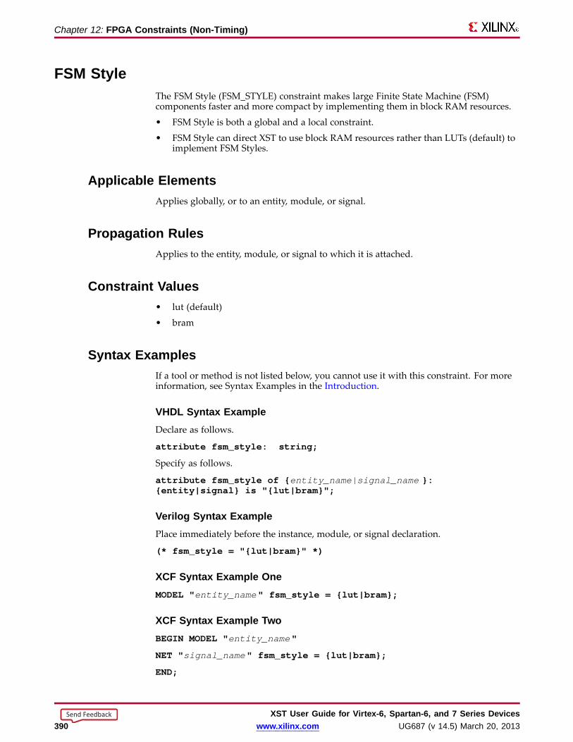
Chapter 12: FPGA Constraints (Non-Timing)
FSM StyleThe FSM Style (FSM_STYLE) constraint makes large Finite State Machine (FSM)components faster and more compact by implementing them in block RAM resources.
• FSM Style is both a global and a local constraint.
• FSM Style can direct XST to use block RAM resources rather than LUTs (default) toimplement FSM Styles.
Applicab le ElementsApplies globally, or to an entity, module, or signal.
Propagation RulesApplies to the entity, module, or signal to which it is attached.
Constraint Values• lut (default)
• bram
Syntax ExamplesIf a tool or method is not listed below, you cannot use it with this constraint. For moreinformation, see Syntax Examples in the Introduction.
VHDL Syntax ExampleDeclare as follows.
attribute fsm_style: string;
Specify as follows.
attribute fsm_style of { entity_name|signal_name }:{entity|signal} is "{lut|bram}";
Verilog Syntax ExamplePlace immediately before the instance, module, or signal declaration.
(* fsm_style = "{lut|bram}" *)
XCF Syntax Example OneMODEL" entity_name " fsm_style = {lut|bram};
XCF Syntax Example TwoBEGIN MODEL" entity_name "
NET " signal_name " fsm_style = {lut|bram};
END;
XST User Guide for Vir tex-6, Spar tan-6, and 7 Series Devices390 www.xilinx.com UG687 (v 14.5) March 20, 2013
Send Feedback

Chapter 12: FPGA Constraints (Non-Timing)
XCF Syntax Example ThreeBEGIN MODEL" entity_name "
INST " instance_name " fsm_style = {lut|bram};
END;
ISE Design Suite Syntax ExampleDefine globally in ISE® Design Suite.
Process > Properties > Synthesis Options > FSM Style
XST User Guide for Vir tex-6, Spar tan-6, and 7 Series DevicesUG687 (v 14.5) March 20, 2013 www.xilinx.com 391
Send Feedback

Chapter 12: FPGA Constraints (Non-Timing)
LUT CombiningThe LUT Combining (LC) constraint merges LUT pairs with common inputs into singledual-output LUT6 elements.
This optimization process may:
• Improve design area.
• Reduce design speed.
Applicab le ElementsApplies globally.
Propagation RulesNot applicable.
Constraint Values• auto (default)
XST tries to make a trade-off between area and speed.
• area
XST performs maximum LUT combining to provide as small an implementation aspossible.
• off
Disables LUT combining.
Syntax ExamplesIf a tool or method is not listed below, you cannot use it with this constraint. For moreinformation, see Syntax Examples in the Introduction.
XST Command Line Syntax ExampleDefine globally with the run command.
-lc {auto|area|off}
ISE Design Suite Syntax ExampleDefine globally in ISE® Design Suite.
Process > Properties > Xilinx-Specific Options > LUT Combining
XST User Guide for Vir tex-6, Spar tan-6, and 7 Series Devices392 www.xilinx.com UG687 (v 14.5) March 20, 2013
Send Feedback
Chapter 12: FPGA Constraints (Non-Timing)
Map Entity on a Single LUTThe Map Entity on a Single LUT (LUT_MAP) constraint forces XST to map a singleblock into a single LUT.• XST issues an error message if a described function in a Register Transfer Level
(RTL) description does not fit in a single LUT.• XST recognizes the Synplify xc_map constraint.
For more information, see Mapping Logic to LUTs.
Using the UNISIM Librar yUse the UNISIM library to directly instantiate LUT components in the HDL code.• Apply INIT to a LUT instance to specify a function that the LUT must execute.• Apply RLOC to the same instance in order to place an instantiated LUT or register
in a particular slice.
Describing the Function in the HDL Sour ce CodeDescribe the function that you want to map into a single LUT in the HDL source code.1. Describe the function in a separate block.2. Attach LUT_MAP to this block to indicate that this block must be mapped into
a single LUT.3. XST calculates the INIT value for the LUT.4. XST preserves this LUT during optimization.
Applicab le ElementsApplies to an entity or module.
Propagation RulesApplies to the entity or module to which it is attached.
Constraint Values• yes [or true (XCF)]• no [or false (XCF)]
Syntax ExamplesIf a tool or method is not listed below, you cannot use it with this constraint. For moreinformation, see Syntax Examples in the Introduction.
VHDL Syntax ExampleDeclare as follows.
attribute lut_map: string;
Specify as follows.
attribute lut_map of entity_name : entity is "{yes|no}";
XST User Guide for Vir tex-6, Spar tan-6, and 7 Series DevicesUG687 (v 14.5) March 20, 2013 www.xilinx.com 393
Send Feedback

Chapter 12: FPGA Constraints (Non-Timing)
Verilog Syntax ExamplePlace immediately before the module declaration or instantiation.
(* lut_map = "{yes|no}" *)
XCF Syntax ExampleMODEL" entity_name " lut_map={yes|no|true|false};
XST User Guide for Vir tex-6, Spar tan-6, and 7 Series Devices394 www.xilinx.com UG687 (v 14.5) March 20, 2013
Send Feedback
Chapter 12: FPGA Constraints (Non-Timing)
Map Logic on BRAMThe Map Logic on BRAM (BRAM_MAP) constraint maps an entire hierarchical block onthe block RAM resources.• BRAM_MAP is both a global and a local constraint.• For more information, see Mapping Logic to Block RAM.
Applicab le ElementsApplies to block RAM components.
Propagation Rules• Isolate the logic (including output register) to be mapped on RAM in a separate
hierarchical level.• Logic that does not fit on a single block RAM is not mapped.• Ensure that the whole entity fits, not just part of it.• The attribute BRAM_MAP is set on the instance or entity.• If XST is unable to infer block RAM, the logic is passed to Global Optimization Goal,
where it is optimized.• The macros are not inferred. Be sure that XST has mapped the logic.
Constraint Values• yes [or true (XCF)]• no [or false (XCF)] (default)
Syntax ExamplesIf a tool or method is not listed below, you cannot use it with this constraint. For moreinformation, see Syntax Examples in the Introduction.
VHDL Syntax ExampleDeclare as follows.
attribute bram_map: string;
Specify as follows.
attribute bram_map of component_name: component is "{yes|no}";
Verilog Syntax ExamplePlace immediately before the module declaration or instantiation.
(* bram_map = "{yes|no}" *)
XCF Syntax Example OneMODEL" entity_name " bram_map = {yes|no|true|false};
XCF Syntax Example TwoBEGIN MODEL" entity_name "
INST " instance_name " bram_map = {yes|no|true|false};
END;
XST User Guide for Vir tex-6, Spar tan-6, and 7 Series DevicesUG687 (v 14.5) March 20, 2013 www.xilinx.com 395
Send Feedback
Chapter 12: FPGA Constraints (Non-Timing)
Max FanoutThe Max Fanout (MAX_FANOUT) constraint limits the fanout of nets or signals.
• Max Fanout:
– Is both a global and a local constraint.
– Has a default value of 100000 (One Hundred Thousand). The value is an integer.
• Large fanouts can interfere with routability. XST tries to limit fanout by duplicatinggates or by inserting buffers.
– This limit is not a technology limit, but a guide to XST.
– This limit is not always observed, especially when this limit is small (less than30).
• In most cases, XST controls fanout by duplicating the gate driving the net with alarge fanout.
– If XST cannot duplicate the gate, XST inserts buffers.
– To protect these buffers against logic trimming at the implementation level,define Keep in the NGC file.
• If the register replication option is set to no, only buffers are used to control fanoutof Flip-Flops and Latches.
• Max Fanout is global for the design, but you can use constraints to control maximumfanout independently for each entity or module or for individual signals.
Actual Net Fanout Less Than Max Fanout Value• If the actual net fanout is less than the Max Fanout value, XST behavior depends on
how Max Fanout is specified.
• XST interprets the value of Max Fanout only as a guidance if the value:
– Is set in ISE® Design Suite.
– Is set in the command line.
– Is applied to a specific hierarchical block.
• If Max Fanout is applied to a specific net, XST does not perform logic replication.Putting Max Fanout on a net may prevent XST from having better timingoptimization.
Example The critical path goes through the net, for which the actual fanout is 80,and sets the Max Fanout value to 100.
– If Max Fanout is specified in ISE Design Suite, XST can replicate it, trying toimprove timing.
– If Max Fanout is applied to the net itself, XST does not perform logic replication.
XST User Guide for Vir tex-6, Spar tan-6, and 7 Series Devices396 www.xilinx.com UG687 (v 14.5) March 20, 2013
Send Feedback
Chapter 12: FPGA Constraints (Non-Timing)
Max Fanout With a Value of Reduce• Max Fanout can take the value reduce.
• The reduce value:
– Has no direct meaning to XST.
– Is considered only during placement and routing. Until then, fanout control isdeferred.
• Max Fanout with a value of reduce:
– Can be applied only to a net.
– Cannot be applied globally.
• XST disables any logic optimization related to the designated net.
– The designated net is preserved in the post-synthesis netlist.
– AMAX_FANOUT=reduce property is attached to the designated net.
• A more global Max Fanout constraint can be defined with an integer value:
– On the command line, or
– With an attribute attached to the entity or module that contains the net
• If such a global Max Fanout constraint has been defined, then:
– The reduce value takes precedence.
– The integer value is ignored for the designated net.
Applicab le ElementsApplies globally, or to an entity, module, or signal.
Exception: When Max Fanout takes the value reduce, it can be applied only to a signal.
Propagation RulesApplies to the entity, module, or signal to which it is attached.
Syntax ExamplesIf a tool or method is not listed below, you cannot use it with this constraint. For moreinformation, see Syntax Examples in the Introduction.
VHDL Syntax ExampleDeclare as follows.
attribute max_fanout: string;
Specify as follows.
attribute max_fanout of { signal_name | entity_name }:{signal|entity} is " integer ";
OR
attribute max_fanout of { signal_name }: {signal} is "reduce";
XST User Guide for Vir tex-6, Spar tan-6, and 7 Series DevicesUG687 (v 14.5) March 20, 2013 www.xilinx.com 397
Send Feedback

Chapter 12: FPGA Constraints (Non-Timing)
Verilog Syntax ExamplePlace immediately before the module or signal declaration.
(* max_fanout = " integer " *)
OR
(* max_fanout = "reduce" *)
XCF Syntax Example OneMODEL" entity_name " max_fanout= integer ;
XCF Syntax Example TwoBEGIN MODEL" entity_name "
NET " signal_name " max_fanout= integer ;
END;
XCF Syntax Example ThreeBEGIN MODEL" entity_name "
NET " signal_name " max_fanout="reduce";
END;
XST Command Line Syntax Example-max_fanout integer
ISE Design Suite Syntax ExampleDefine globally in ISE Design Suite.
Process > Properties > Xilinx-Specific Options > Max Fanout
XST User Guide for Vir tex-6, Spar tan-6, and 7 Series Devices398 www.xilinx.com UG687 (v 14.5) March 20, 2013
Send Feedback
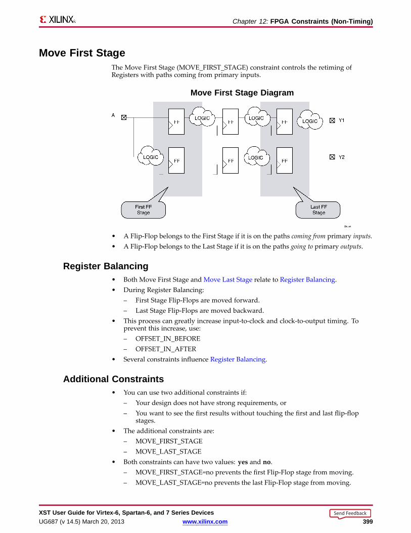
Chapter 12: FPGA Constraints (Non-Timing)
Move First StageThe Move First Stage (MOVE_FIRST_STAGE) constraint controls the retiming ofRegisters with paths coming from primary inputs.
Move First Stage Diagram
• A Flip-Flop belongs to the First Stage if it is on the paths coming from primary inputs.• A Flip-Flop belongs to the Last Stage if it is on the paths going to primary outputs.
Register Balancing• Both Move First Stage and Move Last Stage relate to Register Balancing.• During Register Balancing:
– First Stage Flip-Flops are moved forward.– Last Stage Flip-Flops are moved backward.
• This process can greatly increase input-to-clock and clock-to-output timing. Toprevent this increase, use:– OFFSET_IN_BEFORE– OFFSET_IN_AFTER
• Several constraints influence Register Balancing.
Additional Constraints• You can use two additional constraints if:
– Your design does not have strong requirements, or– You want to see the first results without touching the first and last flip-flop
stages.• The additional constraints are:
– MOVE_FIRST_STAGE– MOVE_LAST_STAGE
• Both constraints can have two values: yes and no.– MOVE_FIRST_STAGE=no prevents the first Flip-Flop stage from moving.– MOVE_LAST_STAGE=no prevents the last Flip-Flop stage from moving.
XST User Guide for Vir tex-6, Spar tan-6, and 7 Series DevicesUG687 (v 14.5) March 20, 2013 www.xilinx.com 399
Send Feedback

Chapter 12: FPGA Constraints (Non-Timing)
Applicab le ElementsApplies to the following only:
• Entire design
• Single modules or entities
• Primary clock signal
Propagation RulesFor Move First Stage propagation rules, see the figure above.
Constraint Values• yes [or true (XCF)] (default)
• no [or false (XCF)]
Syntax ExamplesIf a tool or method is not listed below, you cannot use it with this constraint. For moreinformation, see Syntax Examples in the Introduction.
VHDL Syntax ExampleDeclare as follows.
attribute move_first_stage : string;
Specify as follows.
attribute move_first_stage of {entity_name|signal_name}:{signal|entity} is "{yes|no}";
Verilog Syntax ExamplePlace immediately before the module or signal declaration.
(* move_first_stage = "{yes|no}" *)
XCF Syntax Example OneMODEL" entity_name " move_first_stage={yes|no|true|false};
XCF Syntax Example TwoBEGIN MODEL" entity_name "
NET " primary_clock_signal " move_first_stage={yes|no|true|false};
END;
XST Command Line Syntax ExampleDefine globally with the run command.
-move_first_stage {yes|no}
XST User Guide for Vir tex-6, Spar tan-6, and 7 Series Devices400 www.xilinx.com UG687 (v 14.5) March 20, 2013
Send Feedback

Chapter 12: FPGA Constraints (Non-Timing)
ISE Design Suite Syntax ExampleDefine globally in ISE® Design Suite.
Process > Properties > Xilinx-Specific Options > Move First Flip-Flop Stage
XST User Guide for Vir tex-6, Spar tan-6, and 7 Series DevicesUG687 (v 14.5) March 20, 2013 www.xilinx.com 401
Send Feedback
Chapter 12: FPGA Constraints (Non-Timing)
Move Last StageThe Move Last Stage (MOVE_LAST_STAGE) constraint controls the retiming ofRegisters with paths going to primary outputs.
Both Move Last Stage and Move First Stage relate to Register Balancing.
Applicab le ElementsApplies to the following only:• Entire design• Single modules or entities• Primary clock signal
Propagation RulesSee Move First Stage.
Constraint Values• yes [or true (XCF)] (default)• no [or false (XCF)]
Syntax ExamplesIf a tool or method is not listed below, you cannot use it with this constraint. For moreinformation, see Syntax Examples in the Introduction.
VHDL Syntax ExampleDeclare as follows.
attribute move_last_stage : string;
Specify as follows.
attribute move_last_stage of { entity_name|signal_name }:{signal|entity} is "{yes|no}";
Verilog Syntax ExamplePlace immediately before the module or signal declaration.
(* move_last_stage = "{yes|no}" *)
XCF Syntax Example OneMODEL" entity_name "{move_last_stage={yes|no|true|false};
XCF Syntax Example TwoBEGIN MODEL" entity_name "
NET " primary_clock_signal " move_last_stage={yes|no|true|false};
END;
XST User Guide for Vir tex-6, Spar tan-6, and 7 Series Devices402 www.xilinx.com UG687 (v 14.5) March 20, 2013
Send Feedback

Chapter 12: FPGA Constraints (Non-Timing)
XST Command Line Syntax ExampleDefine globally with the run command.
-move_last_stage {yes|no}
ISE Design Suite Syntax ExampleDefine globally in ISE® Design Suite.
Process > Properties > Xilinx-Specific Options > Move Last Flip-Flop Stage
XST User Guide for Vir tex-6, Spar tan-6, and 7 Series DevicesUG687 (v 14.5) March 20, 2013 www.xilinx.com 403
Send Feedback

Chapter 12: FPGA Constraints (Non-Timing)
Multiplier StyleThe Multiplier Style (MULT_STYLE) constraint controls the manner in which themacrogenerator implements the Multiplier macros.
Applicab le ElementsApplies globally, or to an entity, module, or signal.
Propagation Rules• Applies to the entity, module, or signal to which it is attached.
• Multiplier Style is applicable only through an HDL attribute.
• Multiplier Style is not available as a command line option.
Constraint Values• auto (default)
XST looks for the best implementation for each considered macro.
• block
• pipe_block
Used to pipeline DSP48-based Multipliers.
• kcm
• csd
• lut
• pipe_lut
For pipeline slice-based Multipliers. The implementation style can be manuallyforced to use block Multiplier or LUT resources.
Syntax ExamplesIf a tool or method is not listed below, you cannot use it with this constraint. For moreinformation, see Syntax Examples in the Introduction.
VHDL Syntax ExampleDeclare as follows.
attribute mult_style: string;
Specify as follows.
attribute mult_style of{ signal_name|entity_name }: { signal|entity } is"{auto|block|pipe_block|kcm|csd|lut|pipe_lut}";
XST User Guide for Vir tex-6, Spar tan-6, and 7 Series Devices404 www.xilinx.com UG687 (v 14.5) March 20, 2013
Send Feedback
Chapter 12: FPGA Constraints (Non-Timing)
Verilog Syntax ExamplePlace immediately before the module or signal declaration.
(* mult_style = "{auto|block|pipe_block|kcm|csd|lut|pipe_lut}" *)
XCF Syntax Example OneMODEL" entity_name "mult_style={auto|block|pipe_block|kcm|csd|lut|pipe_lut};
XCF Syntax Example TwoBEGIN MODEL" entity_name "
NET " signal_name "mult_style={auto|block|pipe_block|kcm|csd|lut|pipe_lut};
END;
XST User Guide for Vir tex-6, Spar tan-6, and 7 Series DevicesUG687 (v 14.5) March 20, 2013 www.xilinx.com 405
Send Feedback
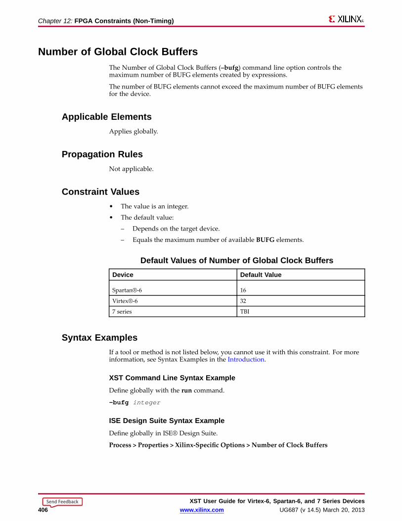
Chapter 12: FPGA Constraints (Non-Timing)
Number of Global Clock Buff ersThe Number of Global Clock Buffers (–bufg) command line option controls themaximum number of BUFG elements created by expressions.
The number of BUFG elements cannot exceed the maximum number of BUFG elementsfor the device.
Applicab le ElementsApplies globally.
Propagation RulesNot applicable.
Constraint Values• The value is an integer.
• The default value:
– Depends on the target device.
– Equals the maximum number of available BUFG elements.
Default Values of Number of Global Clock Buff ersDevice Default Value
Spartan®-6 16
Virtex®-6 32
7 series TBI
Syntax ExamplesIf a tool or method is not listed below, you cannot use it with this constraint. For moreinformation, see Syntax Examples in the Introduction.
XST Command Line Syntax ExampleDefine globally with the run command.
-bufg integer
ISE Design Suite Syntax ExampleDefine globally in ISE® Design Suite.
Process > Properties > Xilinx-Specific Options > Number of Clock Buffers
XST User Guide for Vir tex-6, Spar tan-6, and 7 Series Devices406 www.xilinx.com UG687 (v 14.5) March 20, 2013
Send Feedback
Chapter 12: FPGA Constraints (Non-Timing)
Optimiz e Instantiated PrimitivesThe Optimize Instantiated Primitives (OPTIMIZE_PRIMITIVES) constraint deactivatesthe default whereby XST does not optimize instantiated Xilinx® library primitives.Deactivating the default allows XST to optimize those primitives.
Limitations on Optimization of Instantiated Primitives• If an instantiated primitive has specific constraints such as RLOC applied, XST
preserves it as is.
• XST does not consider all primitives for optimization. Hardware elements suchas MULT18x18, block RAM, and DSP48 are not optimized (modified) even ifoptimization of instantiated primitives is enabled.
Applicab le ElementsApplies globally, or to the designated hierarchical blocks, components, and instances.
Propagation RulesApplies to the component or instance to which it is attached.
Constraint Values• yes [or true (XCF)]
• no [or false (XCF)] (default)
Syntax ExamplesIf a tool or method is not listed below, you cannot use it with this constraint. For moreinformation, see Syntax Examples in the Introduction.
Schematic Syntax Examples• Attach to a valid instance
• Attribute Name
OPTIMIZE_PRIMITIVES
VHDL Syntax ExampleDeclare as follows.
attribute optimize_primitives: string;
Specify as follows.
attribute optimize_primitives of{ component_name|entity_name|label_name }:{component|entity|label} is "{yes|no}";
XST User Guide for Vir tex-6, Spar tan-6, and 7 Series DevicesUG687 (v 14.5) March 20, 2013 www.xilinx.com 407
Send Feedback
Chapter 12: FPGA Constraints (Non-Timing)
Verilog Syntax ExamplePlace immediately before the instance, module or signal declaration.
(* optimize_primitives = "{yes|no}" *)
XCF Syntax ExampleMODEL" entity_name " optimize_primitives = {yes|no|true|false};
XST Command Line Syntax ExampleDefine globally with the run command.
-optimize_primitives {yes|no}
ISE Design Suite Syntax ExampleDefine globally in ISE® Design Suite.
Process > Properties > Xilinx-Specific Options > Optimize Instantiated Primitives
XST User Guide for Vir tex-6, Spar tan-6, and 7 Series Devices408 www.xilinx.com UG687 (v 14.5) March 20, 2013
Send Feedback

Chapter 12: FPGA Constraints (Non-Timing)
Pack I/O Register s Into IOBsThe Pack I/O Registers Into IOBs (IOB) constraint packs Flip-Flops into the I/Os toimprove input and output path timing.
When Pack I/O Registers Into IOBs is set to auto, the action XST takes depends on theOptimization setting:
• area
XST packs Registers as tightly as possible to the IOBs in order to reduce the numberof slices occupied by the design.
• speed
XST packs Registers to the IOBs provided they are not covered by timing constraints(are not taken into account by timing optimization).
♦ For example, if you specify a PERIOD constraint, XST packs a Register to theIOB, provided it is not covered by the PERIOD constraint.
♦ If a Register is covered by timing optimization, but you want to pack it to anIOB, apply the IOB constraint locally to the Register.
For more information about this constraint, see the Constraints Guide (UG625).
XST User Guide for Vir tex-6, Spar tan-6, and 7 Series DevicesUG687 (v 14.5) March 20, 2013 www.xilinx.com 409
Send Feedback
Chapter 12: FPGA Constraints (Non-Timing)
Power ReductionThe Power Reduction (POWER) constraint enables synthesis optimization techniquesto reduce power consumption.• Power optimization is disabled by default.• Even if Power Reduction is enabled, XST still attempts to honor the primary
optimization goal (speed or area) set by Optimization Goal.• Determine whether the optimizations performed to reduce power consumption
negatively impact your primary optimization goal.• Power optimizations are primarily related to block RAM elements. XST tries to
minimize the number of simultaneously active block RAM elements by usingRAM enable features.
For more information about RAM power optimizations, see RAM Style.
Applicab le ElementsApplies to:• A component or entity (VHDL)• A model or label (instance) (Verilog)• A model or INST (in model) (XCF)• The entire design (XST command line)
Propagation RulesApplies to the entity, module, or signal to which it is attached.
Constraint Values• yes [or true (XCF)]• no [or false (XCF)] (default)
Syntax ExamplesIf a tool or method is not listed below, you cannot use it with this constraint. For moreinformation, see Syntax Examples in the Introduction.
VHDL Syntax ExampleDeclare as follows.
attribute power: string;
Specify as follows.
attribute power of { component name|entity_name } :{ component|entity } is "{yes|no}";
Verilog Syntax ExamplePlace immediately before the module declaration or instantiation.
(* power = "{yes|no}" *)
XST User Guide for Vir tex-6, Spar tan-6, and 7 Series Devices410 www.xilinx.com UG687 (v 14.5) March 20, 2013
Send Feedback

Chapter 12: FPGA Constraints (Non-Timing)
XCF Syntax ExampleMODEL" entity_name " power = {yes|no|true|false};
XST Command Line Syntax ExampleDefine globally with the run command.
-power {yes|no}
ISE Design Suite Syntax ExampleDefine globally in ISE® Design Suite.
Process > Properties > Synthesis Options > Power Reduction
XST User Guide for Vir tex-6, Spar tan-6, and 7 Series DevicesUG687 (v 14.5) March 20, 2013 www.xilinx.com 411
Send Feedback
Chapter 12: FPGA Constraints (Non-Timing)
RAM ExtractionThe RAM Extraction (RAM_EXTRACT) constraint enables or disables RAM macroinference.
Applicab le ElementsApplies globally, or to an entity, module, or signal.
Propagation RulesApplies to the entity, module, or signal to which it is attached.
Constraint Values• yes [or true (XCF)] (default)
• no [or false (XCF)]
Syntax ExamplesIf a tool or method is not listed below, you cannot use it with this constraint. For moreinformation, see Syntax Examples in the Introduction.
VHDL Syntax ExampleDeclare as follows.
attribute ram_extract: string;
Specify as follows.
attribute ram_extract of { signal_name | entity_name }:{signal|entity} is "{yes|no}";
Verilog Syntax ExamplePlace immediately before the module or signal declaration.
(* ram_extract = "{yes|no}" *)
XCF Syntax Example OneRAMExtraction Syntax MODEL" entity_name "
ram_extract={yes|no|true|false};
XCF Syntax Example TwoBEGIN MODEL" entity_name "
NET " signal_name " ram_extract={yes|no|true|false};
END;
XST User Guide for Vir tex-6, Spar tan-6, and 7 Series Devices412 www.xilinx.com UG687 (v 14.5) March 20, 2013
Send Feedback

Chapter 12: FPGA Constraints (Non-Timing)
XST Command Line Syntax ExampleDefine globally with the run command.
-ram_extract {yes|no}
ISE Design Suite Syntax ExampleDefine globally in ISE® Design Suite.
Process > Properties > HDL Options > RAM Extraction
XST User Guide for Vir tex-6, Spar tan-6, and 7 Series DevicesUG687 (v 14.5) March 20, 2013 www.xilinx.com 413
Send Feedback

Chapter 12: FPGA Constraints (Non-Timing)
RAM StyleThe RAM Style (RAM_STYLE) constraint controls the way the macrogeneratorimplements the inferred RAM macros.
Use block_power1 and block_power2 to enable two levels of optimizations aimed atreducing power consumption of RAM components implemented on block resources.
block_power1• Is intended to have minimal impact on the primary optimization goal defined by
Optimization Goal (area or speed)
• Is the selected mode when general power optimizations are enabled with the PowerReduction constraint.
• May be specified only as:
– VHDL attribute
– Verilog attribute
– XST Constraint File (XCF) constraint
block_power2• Allows further power reduction
• Can significantly impact area and speed
• May be specified only as:
– VHDL attribute
– Verilog attribute
– XST Constraint File (XCF) constraint
For more information on those optimization techniques, see Block RAM PowerReduction.
Applicab le ElementsApplies globally, or to an entity, module, or signal.
Propagation RulesApplies to the entity, module, or signal to which it is attached.
XST User Guide for Vir tex-6, Spar tan-6, and 7 Series Devices414 www.xilinx.com UG687 (v 14.5) March 20, 2013
Send Feedback
Chapter 12: FPGA Constraints (Non-Timing)
Constraint Values• auto (default)
Instructs XST to look for the best implementation for each inferred RAM, based on:– Whether the description style allows block RAM implementation (synchronous
data read)– Available block RAM resources
• distributedManually forces the implementation to distributed RAM resources
• pipe_distributed– When an inferred RAM is implemented on LUT resources, and several
distributed RAM primitives are required to accommodate its size, multiplexinglogic is created on the RAM data output path. The pipe_distributed valueinstructs XST to use any latency stages available behind the RAM to pipelinethis logic.
– May be specified only as:♦ VHDL attribute♦ Verilog attribute♦ XST Constraint File (XCF) constraint
• blockManually forces the implementation to block RAM. Actual implementation on blockRAM remains conditional on:– A properly synchronized data read, and– Available resources on the device
Syntax ExamplesIf a tool or method is not listed below, you cannot use it with this constraint. For moreinformation, see Syntax Examples in the Introduction.
VHDL Syntax ExampleDeclare as follows.
attribute ram_style: string;
Specify as follows.
attribute ram_style of { signal_name|entity_name }: {signal|entity} is"{auto|block|distributed|pipe_distributed|block_power1|block_power2}";
Verilog Syntax ExamplePlace immediately before the module or signal declaration.
(* ram_style = "{auto|block|distributed|pipe_distributed|block_power1|block_power2}" *)
XCF Syntax Example OneMODEL" entity_name " ram_style={auto|block|distributed|pipe_distributed|block_power1|block_power2};
XCF Syntax Example TwoBEGIN MODEL" entity_name "
NET " signal_name " ram_style={auto|block|distributed|pipe_distributed|block_power1|block_power2};
END;
XST User Guide for Vir tex-6, Spar tan-6, and 7 Series DevicesUG687 (v 14.5) March 20, 2013 www.xilinx.com 415
Send Feedback

Chapter 12: FPGA Constraints (Non-Timing)
XST Command Line Syntax ExampleDefine globally with the run command.
-ram_style {auto|block|distributed}
The pipe_distributed value is not accessible through the command line.
ISE Design Suite Syntax ExampleDefine globally in ISE® Design Suite.
Process > Properties > HDL Options > RAM Style
XST User Guide for Vir tex-6, Spar tan-6, and 7 Series Devices416 www.xilinx.com UG687 (v 14.5) March 20, 2013
Send Feedback

Chapter 12: FPGA Constraints (Non-Timing)
Read CoresThe Use Read Cores (READ_CORES) constraint allows XST to read Electronic DataInterchange Format (EDIF) and NGC core files for timing estimation and deviceutilization control.• By reading a specific core, XST sees how the logic is connected and is able to better
optimize logic around the core.• You can enable or disable read operations on a core by core basis.• Use Read Cores must be disabled in some cases. For example, the PCI™ core must
not be visible to XST, since the logic directly connected to the PCI core is optimizeddifferently from other cores.
For more information, see Cores Processing.
Applicab le ElementsApplies to:• A component or entity (VHDL)• A model or label (instance) (Verilog)• A model or INST (in model) (XCF)• The entire design (XST command line)
The following rules apply:• Since Read Cores can be used with Box Type, the set of objects on which the
constraints are applied must be the same.• If Read Cores is applied to at least a single instance of a block, then Read Cores is
applied to all other instances of this block for the entire design.
Propagation RulesNot applicable.
Constraint Values• yes [or true (XCF)] (default)
Enables cores processing, but maintains the core as a black box and does not furtherincorporate the core into the design.
• no [or false (XCF)]Disables cores processing
• optimizeEnables cores processing, and merges the core netlist into the overall design. Thisvalue is available only in command line mode.
Syntax ExamplesIf a tool or method is not listed below, you cannot use it with this constraint. For moreinformation, see Syntax Examples in the Introduction.
VHDL Syntax ExampleDeclare as follows.
attribute read_cores: string;
XST User Guide for Vir tex-6, Spar tan-6, and 7 Series DevicesUG687 (v 14.5) March 20, 2013 www.xilinx.com 417
Send Feedback
Chapter 12: FPGA Constraints (Non-Timing)
Specify as follows.
attribute read_cores of { component_name|entity_name } :{yes|no|optimize}"; component|entity } is "{yes|no|optimize}";
Verilog Syntax ExamplePlace immediately before the module declaration or instantiation.
(* read_cores = "{yes|no|optimize}" *)
XCF Syntax Example OneMODEL" entity_name " read_cores = {yes|no|true|false|optimize};
XCF Syntax Example TwoBEGIN MODEL" entity_name "
INST " instance_name " read_cores = {yes|no|true|false|optimize};
END;
XST Command Line Syntax Example-read_cores {yes|no|optimize}
ISE Design Suite Syntax ExampleDefine globally in ISE® Design Suite.
Process > Properties > Synthesis Options > Read Cores
The optimize option is not available in ISE Design Suite.
XST User Guide for Vir tex-6, Spar tan-6, and 7 Series Devices418 www.xilinx.com UG687 (v 14.5) March 20, 2013
Send Feedback

Chapter 12: FPGA Constraints (Non-Timing)
Reduce Contr ol SetsThe Reduce Control Sets (REDUCE_CONTROL_SETS) constraint reduces the numberof control sets.
• Reducing the number of control sets:
– Reduces the design area.
– Improves the packing process in MAP.
– Reduces the number of slices even if the number of LUTs increases.
• Reduce Control Sets:
– Applies only to synchronous control signals:
♦ Synchronous set/reset
♦ Clock enable
– Has no effect on asynchronous sets/reset logic.
Applicab le ElementsApplies globally.
Propagation RulesNot applicable.
Constraint Values• auto (default)
XST performs control set optimization.
• no
XST does not perform control set optimization.
Syntax ExamplesIf a tool or method is not listed below, you cannot use it with this constraint. For moreinformation, see Syntax Examples in the Introduction.
XST Command Line Syntax ExampleDefine globally with the run command.
-reduce_control_sets {auto|no}
ISE Design Suite Syntax ExampleDefine globally in ISE® Design Suite.
Process > Properties > Xilinx Specific Options > Reduce Control Sets
XST User Guide for Vir tex-6, Spar tan-6, and 7 Series DevicesUG687 (v 14.5) March 20, 2013 www.xilinx.com 419
Send Feedback
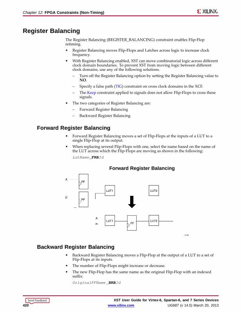
Chapter 12: FPGA Constraints (Non-Timing)
Register BalancingThe Register Balancing (REGISTER_BALANCING) constraint enables Flip-Flopretiming.• Register Balancing moves Flip-Flops and Latches across logic to increase clock
frequency.• With Register Balancing enabled, XST can move combinatorial logic across different
clock domain boundaries. To prevent XST from moving logic between differentclock domains, use any of the following solutions.– Turn off the Register Balancing option by setting the Register Balancing value to
NO.– Specify a false path (TIG) constraint on cross clock domains in the XCF.– The Keep constraint applied to signals does not allow Flip-Flops to cross these
signals.• The two categories of Register Balancing are:
– Forward Register Balancing– Backward Register Balancing
Forwar d Register Balancing• Forward Register Balancing moves a set of Flip-Flops at the inputs of a LUT to a
single Flip-Flop at its output.• When replacing several Flip-Flops with one, select the name based on the name of
the LUT across which the Flip-Flops are moving as shown in the following:LutName _FRBId
Forwar d Register Balancing
Backward Register Balancing• Backward Register Balancing moves a Flip-Flop at the output of a LUT to a set of
Flip-Flops at its inputs.• The number of Flip-Flops might increase or decrease.• The new Flip-Flop has the same name as the original Flip-Flop with an indexed
suffix:OriginalFFName _BRBId
XST User Guide for Vir tex-6, Spar tan-6, and 7 Series Devices420 www.xilinx.com UG687 (v 14.5) March 20, 2013
Send Feedback
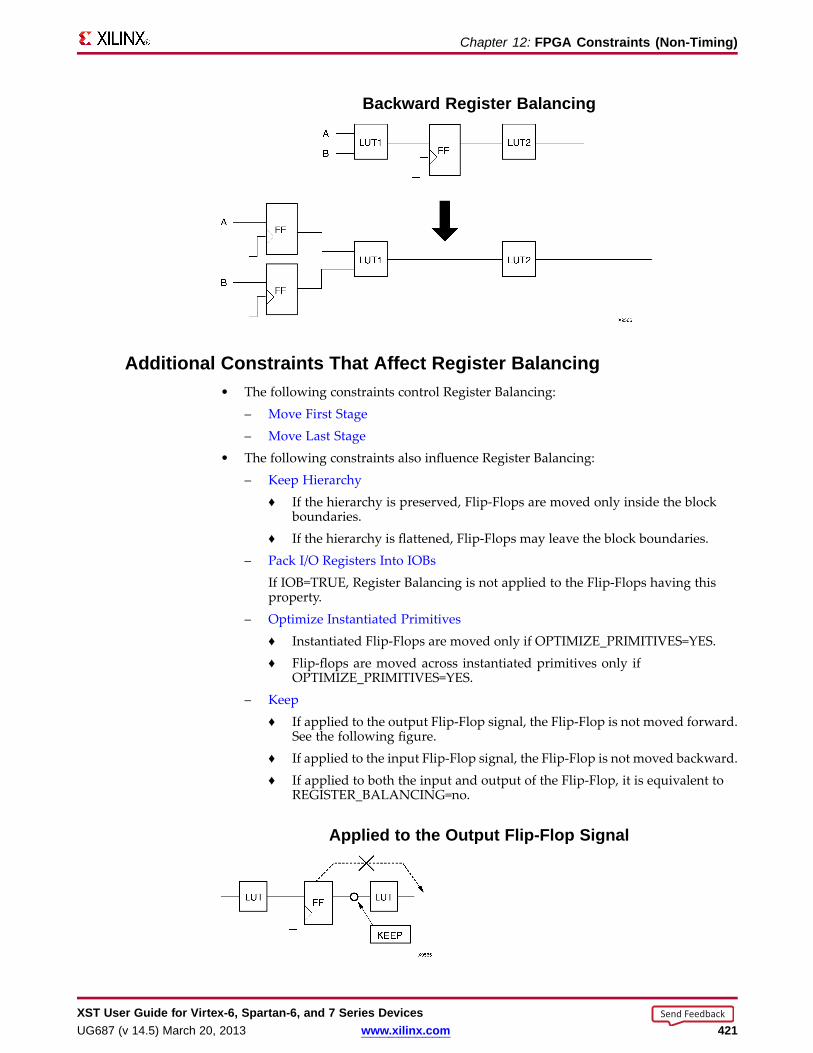
Chapter 12: FPGA Constraints (Non-Timing)
Backward Register Balancing
Additional Constraints That Aff ect Register Balancing• The following constraints control Register Balancing:
– Move First Stage– Move Last Stage
• The following constraints also influence Register Balancing:– Keep Hierarchy
♦ If the hierarchy is preserved, Flip-Flops are moved only inside the blockboundaries.
♦ If the hierarchy is flattened, Flip-Flops may leave the block boundaries.– Pack I/O Registers Into IOBs
If IOB=TRUE, Register Balancing is not applied to the Flip-Flops having thisproperty.
– Optimize Instantiated Primitives♦ Instantiated Flip-Flops are moved only if OPTIMIZE_PRIMITIVES=YES.♦ Flip-flops are moved across instantiated primitives only if
OPTIMIZE_PRIMITIVES=YES.– Keep
♦ If applied to the output Flip-Flop signal, the Flip-Flop is not moved forward.See the following figure.
♦ If applied to the input Flip-Flop signal, the Flip-Flop is not moved backward.♦ If applied to both the input and output of the Flip-Flop, it is equivalent to
REGISTER_BALANCING=no.
Applied to the Output Flip-Flop Signal
XST User Guide for Vir tex-6, Spar tan-6, and 7 Series DevicesUG687 (v 14.5) March 20, 2013 www.xilinx.com 421
Send Feedback

Chapter 12: FPGA Constraints (Non-Timing)
Applicab le ElementsApply Register Balancing:– Globally to the entire design using the command line or ISE® Design Suite– To an entity or module– To a signal corresponding to the Flip-Flop description (RTL)– To a Flip-Flop instance– To the Primary Clock Signal
Propagation RulesApplies to the entity, module, or signal to which it is attached.
Constraint Values• yes [or true (XCF)]
Both forward and backward retiming are allowed.• no [or false (XCF)] (default)
Neither forward nor backward retiming is allowed.• forward
Only forward retiming is allowed.• backward
Only backward retiming is allowed.
Syntax ExamplesIf a tool or method is not listed below, you cannot use it with this constraint. For moreinformation, see Syntax Examples in the Introduction.
VHDL Syntax ExampleDeclare as follows.
attribute register_balancing: string;
Specify as follows.
attribute register_balancing of { signal_name | entity_name }:{signal|entity} is "{yes|no|forward|backward}";
Verilog Syntax ExamplePlace immediately before the module or signal declaration.
* register_balancing = "{yes|no|forward|backward}" *) (
XCF Syntax Example OneMODEL" entity_name "
register_balancing={yes|no|true|false|forward|backward};
XST User Guide for Vir tex-6, Spar tan-6, and 7 Series Devices422 www.xilinx.com UG687 (v 14.5) March 20, 2013
Send Feedback

Chapter 12: FPGA Constraints (Non-Timing)
XCF Syntax Example TwoBEGIN MODEL" entity_name "
NET " primary_clock_signal "register_balancing={yes|no|true|false|forward|backward};
END;
XCF Syntax Example ThreeBEGIN MODEL" entity_name "
INST " instance_name "
register_balancing={yes|no|true|false|forward|backward};
END;
XST Command Line Syntax ExampleDefine globally with the run command.
-register_balancing {yes|no|forward|backward}
ISE Design Suite Syntax ExampleDefine globally in ISE Design Suite.
Process > Properties > Xilinx-Specific Options > Register Balancing
XST User Guide for Vir tex-6, Spar tan-6, and 7 Series DevicesUG687 (v 14.5) March 20, 2013 www.xilinx.com 423
Send Feedback

Chapter 12: FPGA Constraints (Non-Timing)
Register DuplicationThe Register Duplication constraint enables or disables Register replication.
Register duplication can happen for the following reasons:• As part of timing optimization, register with high fanout will be replicated.• For the IOB constraint, a register which is under timing constraint but also with
IOB=true attribute will be replicated.• When a Max Fanout constraint is applied, if the fanout of any register exceeds the
applied max_fanout value.
Applicab le ElementsApplies globally, or to an entity, module, or signal.
Propagation RulesApplies to the entity or module to which it is attached.
Constraint Values• yes [or true (XCF)] (default)• no [or false (XCF)]
When Register Duplication is set to yes, Register replication:• Is enabled.• Is performed during timing optimization and fanout control.
Syntax ExamplesIf a tool or method is not listed below, you cannot use it with this constraint. For moreinformation, see Syntax Examples in the Introduction.
VHDL Syntax ExampleDeclare as follows.
attribute register_duplication: string;
Specify as follows for an entity:
attribute register_duplication of entity_name : entity is"{yes|no}";
Specify as follows for a signal:
attribute register_duplication of signal_name : signal is"{yes|no}";
Verilog Syntax ExamplePlace immediately before the module declaration or instantiation, or the signaldeclaration:
(* register_duplication = "{yes|no}" *)
XCF Syntax Example OneMODEL" entity_name " register_duplication={yes|no|true|false};
XST User Guide for Vir tex-6, Spar tan-6, and 7 Series Devices424 www.xilinx.com UG687 (v 14.5) March 20, 2013
Send Feedback
Chapter 12: FPGA Constraints (Non-Timing)
XCF Syntax Example TwoBEGIN MODEL" entity_name "
NET " signal_name " register_duplication={yes|no|true|false};
END;
XST Command Line Syntax ExampleDefine globally with the run command.
-register_duplication {yes|no}
ISE Design Suite Syntax ExampleDefine globally in ISE® Design Suite.
Process > Properties > Xilinx-Specific Options > Register Duplication
XST User Guide for Vir tex-6, Spar tan-6, and 7 Series DevicesUG687 (v 14.5) March 20, 2013 www.xilinx.com 425
Send Feedback
Chapter 12: FPGA Constraints (Non-Timing)
ROM ExtractionThe ROM Extraction (ROM_EXTRACT) constraint enables ROM macro inference. AROM can usually be inferred from a case statement in which all assigned contexts areconstant values
Applicab le ElementsApplies globally, or to a design element or signal.
Propagation RulesApplies to the entity, module, or signal to which it is attached.
Constraint Values• yes [or true (XCF)] (default)
• no [or false (XCF)]
Syntax ExamplesIf a tool or method is not listed below, you cannot use it with this constraint. For moreinformation, see Syntax Examples in the Introduction.
VHDL Syntax ExampleDeclare as follows.
attribute rom_extract: string;
Specify as follows.
attribute rom_extract of { signal_name | entity_name }:{signal|entity} is "{yes|no}";
Verilog Syntax ExamplePlace immediately before the module or signal declaration.
(* rom_extract = "{yes|no}" *)
XCF Syntax Example OneMODEL" entity_name " rom_extract={yes|no|true|false};*
XCF Syntax Example TwoBEGIN MODEL" entity_name "
NET " signal_name " rom_extract={yes|no|true|false};
END;
XST User Guide for Vir tex-6, Spar tan-6, and 7 Series Devices426 www.xilinx.com UG687 (v 14.5) March 20, 2013
Send Feedback

Chapter 12: FPGA Constraints (Non-Timing)
XST Command Line Syntax ExampleDefine globally with the run command.
-rom_extract {yes|no}
ISE Design Suite Syntax ExampleDefine globally in ISE® Design Suite.
Process > Properties > HDL Options > ROM Extraction
XST User Guide for Vir tex-6, Spar tan-6, and 7 Series DevicesUG687 (v 14.5) March 20, 2013 www.xilinx.com 427
Send Feedback

Chapter 12: FPGA Constraints (Non-Timing)
ROM StyleThe ROM Style (ROM_STYLE) constraint controls how the macrogenerator implementsthe inferred ROM macros.
• ROM Extraction must be set to yes in order to use ROM Style.
• XST looks for the best implementation for each inferred ROM.
• You can manually force the implementation style to use block RAM or LUTresources.
Applicab le ElementsApplies globally, or to an entity, module, or signal.
Propagation RulesApplies to the entity, module, or signal to which it is attached.
Constraint Values• auto (default)
• block
• distributed
Syntax ExamplesIf a tool or method is not listed below, you cannot use it with this constraint. For moreinformation, see Syntax Examples in the Introduction.
VHDL Syntax ExampleROM Extraction must be set to yes for ROM Style to take effect.
Declare as follows.
attribute rom_style: string;
Specify as follows.
attribute rom_style of { signal_name | entity_name }:{signal|entity} is "{auto|block|distributed}";
Verilog Syntax ExamplePlace immediately before the module or signal declaration.
(* rom_style = "{auto|block|distributed}" *)
XCF Syntax Example OneROM Extraction must be set to yes for ROM Style to take effect.
MODEL" entity_name " rom_style={auto|block|distributed};
XST User Guide for Vir tex-6, Spar tan-6, and 7 Series Devices428 www.xilinx.com UG687 (v 14.5) March 20, 2013
Send Feedback
Chapter 12: FPGA Constraints (Non-Timing)
XCF Syntax Example TwoROM Extraction must be set to yes for ROM Style to take effect.
BEGIN MODEL" entity_name "
NET " signal_name " rom_style={auto|block|distributed};
END;
XST Command Line Syntax ExampleROM Extraction must be set to yes for ROM Style to take effect.
Define globally with the run command.
-rom_style {auto|block|distributed}
ISE Design Suite Syntax ExampleROM Extraction must be set to yes for ROM Style to take effect.
Define globally in ISE® Design Suite.
Process > Properties > HDL Options > ROM Style
XST User Guide for Vir tex-6, Spar tan-6, and 7 Series DevicesUG687 (v 14.5) March 20, 2013 www.xilinx.com 429
Send Feedback

Chapter 12: FPGA Constraints (Non-Timing)
Shift Register ExtractionThe Shift Register Extraction (SHREG_EXTRACT) constraint enables Shift Registermacro inference.
• Enabling Shift Register Extraction results in the usage of dedicated hardwareresources such as SRL16 and SRLC16.
• For more information, see Chapter 7, HDL Coding Techniques.
Applicab le ElementsApplies globally, or to a design element or signal.
Propagation RulesApplies to the design elements or signals to which it is attached.
Constraint Values• yes [or true (XCF)] (default)
• no [or false (XCF)]
Syntax ExamplesIf a tool or method is not listed below, you cannot use it with this constraint. For moreinformation, see Syntax Examples in the Introduction.
VHDL Syntax ExampleDeclare as follows.
attribute shreg_extract : string;
Specify as follows.
attribute shreg_extract of { signal_name | entity_name }:{signal|entity} is "{yes|no}";
Verilog Syntax ExamplePlace immediately before the module or signal declaration.
(* shreg_extract = "{yes|no}" *)
XCF Syntax Example OneMODEL" entity_name " shreg_extract={yes|no|true|false};
XST User Guide for Vir tex-6, Spar tan-6, and 7 Series Devices430 www.xilinx.com UG687 (v 14.5) March 20, 2013
Send Feedback
Chapter 12: FPGA Constraints (Non-Timing)
XCF Syntax Example TwoBEGIN MODEL" entity_name "
NET " signal_name " shreg_extract={yes|no|true|false};
END;
XST Command Line Syntax ExampleDefine globally with the run command.
-shreg_extract {yes|no}
ISE Design Suite Syntax ExampleDefine globally in ISE® Design Suite.
Process > Properties > HDL Options > Shift Register Extraction
XST User Guide for Vir tex-6, Spar tan-6, and 7 Series DevicesUG687 (v 14.5) March 20, 2013 www.xilinx.com 431
Send Feedback
Chapter 12: FPGA Constraints (Non-Timing)
Shift Register Minim um SizeThe Shift Register Minimum Size (SHREG_MIN_SIZE) constraint controls the minimumlength of Shift Registers that are inferred and implemented using SRL-type resources.• Shift Registers below the specified limit are implemented using simple Flip-Flops.• Using SRL-type resources excessively to implement small Shift Register macros
(such as 2-bit Shift Registers) may lead to undesirable placement restrictions forother design elements. This may eventually degrade circuit performance.
• When Shift Register Minimum Size is specified, XST forces implementation of ShiftRegisters below a designated length by using simple Flip-Flop resources.
• In Spartan®-6 devices, a single SliceM is available for every four Slices:– SliceL– SliceM– SliceX– SliceYThis availability makes this element particularly scarce and valuable, and mayjustify saving it for better use, such as real LUT RAM applications.
Applicab le Elements• Shift Register Minimum Size is available only as an XST option, defining a global
inference threshold for the whole design.• If you need to more finely control inference of individual Shift Registers, use Shift
Register Minimum Size in conjunction with Shift Register Extraction. You can applyShift Register Extraction to designated design elements.
Propagation RulesNot applicable.
Constraint ValuesThe constraint value is an integer.• The value is a natural value of 2 or higher.• The default value is 2.
Syntax ExamplesIf a tool or method is not listed below, you cannot use it with this constraint. For moreinformation, see Syntax Examples in the Introduction.
XST Command Line Syntax ExampleDefine globally with the run command.
-shreg_min_size integer
ISE Design Suite Syntax ExampleDefine globally in ISE® Design Suite.
Process > Properties > HDL Options > Shift Register Minimum Size
XST User Guide for Vir tex-6, Spar tan-6, and 7 Series Devices432 www.xilinx.com UG687 (v 14.5) March 20, 2013
Send Feedback
Chapter 12: FPGA Constraints (Non-Timing)
Slice (LUT-FF Pairs) Utilization RatioThe Slice (LUT-FF Pairs) Utilization Ratio (SLICE_UTILIZATION_RATIO) constraintdefines the area size of LUT-FF pairs that XST must not exceed during timingoptimization.• The area size of LUT-FF pairs is defined in 1) absolute numbers, or 2) a percent
of total numbers.• If the area constraint cannot be satisfied, XST makes timing optimization regardless
of the area constraint.• To disable automatic resource management, specify -1 as a constraint value.
For more information, see Speed Optimization Under Area Constraint.
Applicab le ElementsApplies globally, or to a VHDL entity or Verilog module.
Propagation RulesApplies to the entity or module to which it is attached.
Syntax ExamplesIf a tool or method is not listed below, you cannot use it with this constraint. For moreinformation, see Syntax Examples in the Introduction.
VHDL Syntax ExampleDeclare as follows.
attribute slice_utilization_ratio: string;
Specify as follows.
attribute slice_utilization_ratio of entity_name : entity is" integer ";
attribute slice_utilization_ratio of entity_name : entity is" integer %";
attribute slice_utilization_ratio of entity_name : entity is" integer #";
In these examples:• XST interprets the integer values in the first two attributes as a percentage.• XST interprets the integer value in the last attribute as an absolute number of slices
or FF-LUT pairs.
Verilog Syntax ExamplePlace immediately before the module declaration or instantiation.
(* slice_utilization_ratio = " integer " *)
(* slice_utilization_ratio = " integer %" *)
(* slice_utilization_ratio = " integer #" *)
XST User Guide for Vir tex-6, Spar tan-6, and 7 Series DevicesUG687 (v 14.5) March 20, 2013 www.xilinx.com 433
Send Feedback

Chapter 12: FPGA Constraints (Non-Timing)
In these examples:
• XST interprets the integer values in the first two attributes as a percentage.
• XST interprets the integer values in the last attribute as an absolute number of slicesor FF-LUT pairs.
XCF Syntax Example ThreeMODEL" entity_name " slice_utilization_ratio=" integer #";*
• In this example:
– XST interprets the integer values in the first two lines as a percentage.
– XST interprets the integer values in the last line as an absolute number of slicesor FF-LUT pairs.
• There must be no space between the integer value and the percent (%) or pound(#) characters.
• The integer value range is -1 to 100when percent (%) is used or both percent (%) andpound (#) are omitted.
• You must surround the integer value and the percent (%) and pound (#) characterswith double quotes. The percent (%) and pound (#) characters are special charactersin the XST Constraint File (XCF).
XST Command Line Syntax ExampleDefine globally with the run command.
-slice_utilization_ratio integer
-slice_utilization_ratio integer %
-slice_utilization_ratio integer #
In these examples:
• XST interprets the integer values in the first two lines as a percentage.
• XST interprets the integer values in the last line as an absolute number of slicesor FF-LUT pairs.
The integer value range is -1 to 100 when percent (%) is used or both percent (%) andpound (#) are omitted.
ISE Design Suite Syntax ExampleDefine globally in ISE® Design Suite.
• Process > Properties > Synthesis Options > Slice Utilization Ratio, or
• Process > Properties > Synthesis Options > LUT-FF Pairs Utilization Ratio
In ISE Design Suite:
• You can define the value of Slice (LUT-FF Pairs) Utilization Ratio only as apercentage.
• You cannot define the value as an absolute number of slices.
XST User Guide for Vir tex-6, Spar tan-6, and 7 Series Devices434 www.xilinx.com UG687 (v 14.5) March 20, 2013
Send Feedback

Chapter 12: FPGA Constraints (Non-Timing)
Slice (LUT-FF Pairs) Utilization Ratio DeltaThe Slice (LUT-FF Pairs) Utilization Ratio Delta constraint:
• Is represented as SLICE_UTILIZATION_RATIO_MAXMARGIN in code.
• Defines the tolerance margin for Slice (LUT-FF Pairs) Utilization Ratio.
– The value of the parameter is defined as:
♦ A percentage, or
♦ An absolute number of slices or LUT-FF Pairs.
– If the ratio is within the margin set, the constraint is met and timing optimizationcan continue.
For more information, see Speed Optimization Under Area Constraint.
Applicab le ElementsApplies globally, or to a VHDL entity or Verilog module.
Propagation RulesApplies to the entity or module to which it is attached.
Syntax ExamplesIf a tool or method is not listed below, you cannot use it with this constraint. For moreinformation, see Syntax Examples in the Introduction.
VHDL Syntax ExampleDeclare as follows.
attribute slice_utilization_ratio_maxmargin: string;
Specify as follows.
attribute slice_utilization_ratio_maxmargin of entity_name :entity is " integer ";
attribute slice_utilization_ratio_maxmargin of entity_name :entity is " integer %";
attribute slice_utilization_ratio_maxmargin of entity_name :entity is " integer #";
• XST interprets the integer values in the first two attributes as a percentage.
• XST interprets the integer values in the last attribute as an absolute number of slicesor FF-LUT pairs.
• The integer value range is 0 to 100 when:
– Percent (%) is used, or
– Both percent (%) and pound (#) are omitted.
XST User Guide for Vir tex-6, Spar tan-6, and 7 Series DevicesUG687 (v 14.5) March 20, 2013 www.xilinx.com 435
Send Feedback

Chapter 12: FPGA Constraints (Non-Timing)
Verilog Syntax ExamplePlace immediately before the module declaration or instantiation.
(* slice_utilization_ratio_maxmargin = " integer " *)
(* slice_utilization_ratio_maxmargin = " integer %" *)
(* slice_utilization_ratio_maxmargin = " integer #" *)
• XST interprets the integer values in the first two attributes as a percentage.
• XST interprets the integer values in the last attribute as an absolute number of slicesor FF-LUT pairs.
XCF Syntax Example ThreeMODEL" entity_name "slice_utilization_ratio_maxmargin=" integer# ";
• XST interprets the integer values in the first two lines as a percentage.
• XST interprets the integer values in the last line as an absolute number of slicesor FF-LUT pairs.
• There must be no space between the integer value and the percent %) or pound(#) characters.
• You must surround the integer value and the percent (%) and pound (#) characterswith double quotes because the percent (%) and pound (#) characters are specialcharacters in the XST Constraint File (XCF).
• The integer value range is 0 to 100when percent (%) is used or both percent (%) andpound (#) are omitted).
XST Command Line Syntax ExampleDefine globally with the run command.
-slice_utilization_ratio_maxmargin integer
-slice_utilization_ratio_maxmargin integer %
-slice_utilization_ratio_maxmargin integer #
In these examples, XST interprets the integer values in the first two lines as a percentage,and in the last line as an absolute number of slices or FF-LUT pairs.
The integer value range is 0 to 100 when percent (%) is used or both percent (%) andpound (#) are omitted.
XST User Guide for Vir tex-6, Spar tan-6, and 7 Series Devices436 www.xilinx.com UG687 (v 14.5) March 20, 2013
Send Feedback

Chapter 12: FPGA Constraints (Non-Timing)
Use Carry ChainThe Use Carry Chain (USE_CARRY_CHAIN) constraint:• Is both a global and a local constraint.• Can deactivate carry chain use for macro generation.
Although XST uses carry chain resources to implement certain macros, you cansometimes obtain better results by not using carry chain.
Applicab le ElementsApplies globally, or to signals.
Propagation RulesApplies to the signal to which it is attached.
Constraint Values• yes [or true (XCF)] (default)• no [or false (XCF)]
Syntax ExamplesIf a tool or method is not listed below, you cannot use it with this constraint. For moreinformation, see Syntax Examples in the Introduction.
Schematic Syntax Examples• Attach to a valid instance• Attribute Name
USE_CARRY_CHAIN
VHDL Syntax ExampleDeclare as follows.
attribute use_carry_chain: string;
Specify as follows.
attribute use_carry_chain of signal_name : signal is "{yes|no}";
Verilog Syntax ExamplePlace immediately before the signal declaration.
(* use_carry_chain = "{yes|no}" *)
XCF Syntax Example OneMODEL" entity_name " use_carry_chain={yes|no|true|false};
XCF Syntax Example TwoBEGIN MODEL" entity_name "
NET " signal_name " use_carry_chain={yes|no|true|false};
END;
XST User Guide for Vir tex-6, Spar tan-6, and 7 Series DevicesUG687 (v 14.5) March 20, 2013 www.xilinx.com 437
Send Feedback

Chapter 12: FPGA Constraints (Non-Timing)
XST Command Line Syntax ExampleDefine globally with the run command.
-use_carry_chain {yes|no}
XST User Guide for Vir tex-6, Spar tan-6, and 7 Series Devices438 www.xilinx.com UG687 (v 14.5) March 20, 2013
Send Feedback

Chapter 12: FPGA Constraints (Non-Timing)
Use Clock EnableThe Clock Enable (USE_CLOCK_ENABLE) constraint enables or disables clock enablingin Flip-Flops.• Clock Enable is usually disabled in ASIC prototyping.• When Use Clock Enable is set to no, XST does not use Clock Enable resources
during final implementation.• For some designs, putting Clock Enable on the data input of the Flip-Flop may
optimize logic and give better Quality of Results (QoR).• In auto mode, XST tries to estimate a trade-off between:
– Using a dedicated Clock Enable input of a Flip-Flop input, and– Putting Clock Enable logic on the D input of a Flip-Flop.
• If you instantiate a Flip-Flop yourself, XST removes the Clock Enable only ifOptimize Instantiated Primitives is set to yes.
Applicab le ElementsApplies to:• An entire design through the XST command line• A particular block (entity, architecture, component)• A signal representing the output of a flip-flop• An instance representing an instantiated flip-flop
Propagation RulesApplies to an entity, component, module, signal, or instance to which it is attached.
Constraint Values• auto (default)• yes [or true (XCF)]• no [or false (XCF)]
Syntax ExamplesIf a tool or method is not listed below, you cannot use it with this constraint. For moreinformation, see Syntax Examples in the Introduction.
VHDL Syntax ExampleDeclare as follows.
attribute use_clock_enable: string;
Specify as follows.
attribute use_clock_enable of{entity_ name|component_ name|signal_ name|instance_ name} :{entity|component|signal|label} is "{auto|yes|no}";
XST User Guide for Vir tex-6, Spar tan-6, and 7 Series DevicesUG687 (v 14.5) March 20, 2013 www.xilinx.com 439
Send Feedback

Chapter 12: FPGA Constraints (Non-Timing)
Verilog Syntax ExamplePlace immediately before the instance, module or signal declaration.
(* use_clock_enable = "{auto|yes|no}" *)
XCF Syntax Example OneMODEL" entity_name " use_clock_enable={auto|yes|no|true|false};
XCF Syntax Example TwoBEGIN MODEL" entity_name "
NET " signal_name " use_clock_enable={auto|yes|no|true|false};
END;
XCF Syntax Example ThreeBEGIN MODEL" entity_name "
INST " instance_name " use_clock_enable={auto|yes|no|true|false};
END;
XST Command Line Syntax ExampleDefine globally with the run command.
-use_clock_enable {auto|yes|no}
ISE Design Suite Syntax ExampleDefine globally in ISE® Design Suite.
Process > Properties > Xilinx-Specific Options > Use Clock Enable
XST User Guide for Vir tex-6, Spar tan-6, and 7 Series Devices440 www.xilinx.com UG687 (v 14.5) March 20, 2013
Send Feedback
Chapter 12: FPGA Constraints (Non-Timing)
Use DSP Bloc kThe Use DSP Block (USE_DSP48) constraint enables or disables the use of DSP blockresources.
DSP Bloc k Resour ces• Use DSP Utilization Ratio in auto and automaxmodes to further control the number
of DSP block resources used by synthesis. XST assumes that all available DSP blockscan be used.
• Macros such as Multiply-Add/Sub and Multiply-Accumulate are treated as acomposition of simpler macros such as:
– Multipliers
– Accumulators
– Registers
• To maximize performance, XST performs these aggregations aggressively. XSTattempts to use all pipelining stages in the DSP block.
• Use Keep to control how XST aggregates those basic macros into a DSP block. Forexample, when two Register stages are available before a multiplication operand,insert Keep between them to prevent one of the Register stages from beingimplemented in the DSP block.
• For more information on supported macros and their implementation control, seeChapter 7, HDL Coding Techniques.
Applicab le Elements• An entire design through the XST command line
• A particular block (entity, architecture, component)
• A signal representing a macro described at the RTL level
Propagation RulesApplies to the entity, component, module, or signal to which it is attached.
XST User Guide for Vir tex-6, Spar tan-6, and 7 Series DevicesUG687 (v 14.5) March 20, 2013 www.xilinx.com 441
Send Feedback

Chapter 12: FPGA Constraints (Non-Timing)
Constraint Values• auto (default)
XST selectively implements arithmetic logic to DSP blocks, and seeks to maximizecircuit performance.
– Macros such as the following are considered for DSP block implementation:
♦ Multiply
♦ Multiply-Add/Sub
♦ Multiply-Accumulate
– XST looks for opportunities to leverage the cascading capabilities of DSP blocks.
– Other macros are implemented on slice logic, including:
♦ Adders
♦ Counters
♦ standalone Accumulators
• automax
XST attempts to maximize DSP block utilization within the limits of availableresources on the selected device.
– In addition to the macros considered in auto mode, automax considersadditional functions as candidates for DSP block implementation, including:
♦ Adders
♦ Counters
♦ standalone Accumulators
– Xilinx® recommends that you use automax when a tightly packed device isyour primary concern, and you are attempting to free up LUT resources.
Attention Using automax may degrade circuit performance compared to thedefault auto mode. Do not use automax when performance is your primaryimplementation goal.
• yes [or true (XCF)]
Allows you to manually force implementation of arithmetic logic to DSP blocks.
– Use yes primarily to force individual functions to DSP resources.
– Xilinx does not recommend applying yes globally, since XST does not checkactual DSP resources availability in this mode, and may oversubscribe DSPblocks.
Attention With a value of yes, the decision to implement a function in a DSP blockignores both the actual availability of DSP resources on the selected device, and anymaximum allocation defined with the DSP Utilization Ratio constraint. As a result,the design may use more DSP resources than are available or budgeted.
• no [or false (XCF)]
Allows you to manually prevent implementation of designated logic on DSPresources.
XST User Guide for Vir tex-6, Spar tan-6, and 7 Series Devices442 www.xilinx.com UG687 (v 14.5) March 20, 2013
Send Feedback
Chapter 12: FPGA Constraints (Non-Timing)
Syntax ExamplesIf a tool or method is not listed below, you cannot use it with this constraint. For moreinformation, see Syntax Examples in the Introduction.
VHDL Syntax ExampleDeclare as follows.
attribute use_dsp48: string;
Specify as follows.
attribute use_dsp48 of "entity_ name|component_ name|signal_ name}:{entity|component|signal} is "{auto|automax|yes|no}";
Verilog Syntax ExamplePlace immediately before the instance, module or signal declaration.
(* use_dsp48 = "{auto|automax|yes|no}" *)
XCF Syntax Example OneMODEL" entity_name " use_dsp48={auto|automax|yes|no|true|false};
XCF Syntax Example TwoBEGIN MODEL" entity_name "
NET " signal_name " use_dsp48={auto|automax|yes|no|true|false};
END;
XST Command Line Syntax ExampleDefine globally with the run command.
-use_dsp48 {auto|automax|yes|no}
ISE Design Suite Syntax ExampleDefine globally in ISE® Design Suite.
Process > Properties > HDL Options > Use DSP Block
XST User Guide for Vir tex-6, Spar tan-6, and 7 Series DevicesUG687 (v 14.5) March 20, 2013 www.xilinx.com 443
Send Feedback

Chapter 12: FPGA Constraints (Non-Timing)
Use Low Skew LinesThe Use Low Skew Lines (USELOWSKEWLINES) constraint:
• Is a basic routing constraint.
• Prevents XST from using dedicated clock resources and logic replication duringsynthesis based on the value of Max Fanout.
• Specifies the use of low skew routing resources for any net.
For more information about this constraint, see the Constraints Guide (UG625).
XST User Guide for Vir tex-6, Spar tan-6, and 7 Series Devices444 www.xilinx.com UG687 (v 14.5) March 20, 2013
Send Feedback

Chapter 12: FPGA Constraints (Non-Timing)
Use Synchronous SetThe Use Synchronous Set (USE_SYNC_SET) constraint enables or disables thesynchronous set function in Flip-Flops.• Use Synchronous Set is usually disabled in ASIC prototyping.• XST does not use synchronous set resources during final implementation if Use
Synchronous Set has a value of no.• Putting the synchronous set function on the data input of a Flip-Flop may allow for
better logic optimization and give better Quality of Results (QoR).• In auto mode, XST tries to estimate a trade-off between:
– Using dedicated Synchronous Set input of a Flip-Flop input, and– Putting Synchronous Set logic on the D input of a Flip-Flop.
• If you instantiate a Flip-Flop yourself, XST removes the synchronous set only ifOptimize Instantiated Primitives is set to yes.
Applicab le ElementsApplies to:• An entire design through the XST command line• A particular block (entity, architecture, component)• A signal representing the output of a flip-flop• An instance representing an instantiated flip-flop
Propagation RulesApplies to an entity, component, module, signal, or instance to which it is attached.
Constraint Values• auto (default)• yes [or true (XCF)]• no [or false (XCF)]
Syntax ExamplesIf a tool or method is not listed below, you cannot use it with this constraint. For moreinformation, see Syntax Examples in the Introduction.
VHDL Syntax ExampleDeclare as follows.
attribute use_sync_set: string;
Specify as follows.
attribute use_sync_set of{entity_ name|component_ name|signal_ name|instance_ name}:{entity|component|signal|label} is "{auto|yes|no}";
XST User Guide for Vir tex-6, Spar tan-6, and 7 Series DevicesUG687 (v 14.5) March 20, 2013 www.xilinx.com 445
Send Feedback

Chapter 12: FPGA Constraints (Non-Timing)
Verilog Syntax ExamplePlace immediately before the instance, module or signal declaration.
(* use_sync_set = "{auto|yes|no}" *)
XCF Syntax Example OneMODEL" entity_name " use_sync_set={auto|yes|no|true|false};
XCF Syntax Example TwoBEGIN MODEL" entity_name "
NET " signal_name " use_sync_set={auto|yes|no|true|false};
END;
XCF Syntax Example ThreeBEGIN MODEL" entity_name "
INST " instance_name " use_sync_set={auto|yes|no|true|false };
END;
XST Command Line Syntax ExampleDefine globally with the run command.
-use_sync_set {auto|yes|no}
ISE Design Suite Syntax ExampleDefine globally in ISE® Design Suite.
Process > Properties > Xilinx-Specific Options > Use Synchronous Set
XST User Guide for Vir tex-6, Spar tan-6, and 7 Series Devices446 www.xilinx.com UG687 (v 14.5) March 20, 2013
Send Feedback
Chapter 12: FPGA Constraints (Non-Timing)
Use Synchronous ResetThe Use Synchronous Reset (USE_SYNC_RESET) constraint enables or disables thesynchronous reset function in Flip-Flops.• Use Synchronous Reset is usually disabled in ASIC prototyping.• XST does not use synchronous reset resources during final implementation if Use
Synchronous Reset has a value of no or false.• Putting the synchronous reset function on the data input of a Flip-Flop may allow for
better logic optimization and give better Quality of Results (QoR) for some designs.• In auto mode, XST tries to estimate a trade-off between:
– Using dedicated Synchronous Reset input of a Flip-Flop input, and– Putting Synchronous Reset logic on the D input of a Flip-Flop.
• If you instantiate a Flip-Flop yourself, XST removes the synchronous reset only ifOptimize Instantiated Primitives is set to yes.
Applicab le ElementsApplies to:• An entire design through the XST command line• A particular block (entity, architecture, component)• A signal representing the output of a flip-flop• An instance representing an instantiated flip-flop
Propagation RulesApplies to an entity, component, module, signal, or instance to which it is attached.
Constraint Values• auto (default)• yes [or true (XCF)]• no [or false (XCF)]
Syntax ExamplesIf a tool or method is not listed below, you cannot use it with this constraint. For moreinformation, see Syntax Examples in the Introduction.
VHDL Syntax ExampleDeclare as follows.
attribute use_sync_reset: string;
Specify as follows.
attribute use_sync_reset of{entity_ name|component_ name|signal_ name|instance_ name}: is"{entity|component|signal|label; is {auto|yes|no}";
Verilog Syntax ExamplePlace immediately before the instance, module, or signal declaration.
(* use_sync_reset = "{auto|yes|no}" *)
XST User Guide for Vir tex-6, Spar tan-6, and 7 Series DevicesUG687 (v 14.5) March 20, 2013 www.xilinx.com 447
Send Feedback
Chapter 12: FPGA Constraints (Non-Timing)
XCF Syntax Example OneMODEL" entity_name " use_sync_reset={auto|yes|no|true|false};
XCF Syntax Example TwoBEGIN MODEL" entity_name "
NET " signal_name " use_sync_reset={auto|yes|no|true|false};
END;
XCF Syntax Example ThreeBEGIN MODEL" entity_name "
INST " instance_name " use_sync_reset={auto|yes|no|true|false};
END;
XST Command Line Syntax ExampleDefine globally with the run command.
-use_sync_reset {auto|yes|no}
ISE Design Suite Syntax ExampleDefine globally in ISE® Design Suite.
Process > Properties > Xilinx-Specific Options > Use Synchronous Reset
XST User Guide for Vir tex-6, Spar tan-6, and 7 Series Devices448 www.xilinx.com UG687 (v 14.5) March 20, 2013
Send Feedback
Chapter 13
Timing ConstraintsThis chapter discusses XST timing constraints.
For most constraints, this chapter gives the following information:• Constraint Description• Applicable Elements• Propagation Rules• Constraint Values• Syntax Examples
Appl ying Timing Constraints• Apply timing constraints using any of the following methods:
– Global Optimization Goal– User Constraints File (UCF)– XST Constraint File (XCF)
• The following options affect timing constraint processing, regardless of how thetiming constraints are applied:– Clock Signal– Cross Clock Analysis– Write Timing Constraints
Appl ying Timing Constraints With Global Optimization GoalYou can apply timing constraints with the Global Optimization Goal command lineoption.• Use Global Optimization Goal to apply the five global timing constraints:
– ALLCLOCKNETS– OFFSET_IN_BEFORE– OFFSET_OUT_AFTER– INPAD_TO_OUTPAD– MAX_DELAY
• These constraints:– Are applied globally.– Cannot have a specified value. XST optimizes them for best performance.– Are overridden by constraints in the User Constraints File (UCF).
XST User Guide for Vir tex-6, Spar tan-6, and 7 Series DevicesUG687 (v 14.5) March 20, 2013 www.xilinx.com 449
Send Feedback
Chapter 13: Timing Constraints
Appl ying Timing Constraints With a User Constraints File (UCF)You can apply timing constraints with a User Constraints File (UCF).
• Use the UCF to apply timing constraints using native UCF syntax.
• XST supports constraints such as:
– Timing Name
– Timegroup
– Period
– Timing Ignore
– From-To
• XST supports wildcards and hierarchical names with these constraints.
Appl ying Timing Constraints With the XST Constraint File (XCF)You can apply timing constraints with the XST Constraint File (XCF).
• Xilinx® recommends that you use a forward slash (/) as a hierarchy separatorinstead of an underscore (_).
• If XST does not support all or part of a specified timing constraint:
– XST issues a warning.
– XST ignores the unsupported timing constraint (or unsupported part of it) inthe Timing Optimization step.
• If Write Timing Constraints is set to yes, XST propagates the entire constraint to thefinal netlist, even if it was ignored at the Timing Optimization step.
• An XCF supports the following timing constraints:
– Period
– Offset
– From-To
– Timing Name
– Timing Name on a Net
– Timegroup
– Timing Ignore
XST User Guide for Vir tex-6, Spar tan-6, and 7 Series Devices450 www.xilinx.com UG687 (v 14.5) March 20, 2013
Send Feedback
Chapter 13: Timing Constraints
Clock SignalThe Clock Signal (CLOCK_SIGNAL) constraint defines a clock signal when the signalgoes through combinatorial logic before being connected to the clock input of a Flip-Flop.
• XST cannot identify which input pin or internal signal is the real clock signal.
• Use Clock Signal to define the signal.
Applicab le ElementsApplies to signals.
Propagation RulesApplies to clock signals.
Constraint Values• yes [or true (XCF)] (default)
• no [or false (XCF)]
Syntax ExamplesIf a tool or method is not listed below, you cannot use it with this constraint. For moreinformation, see Syntax Examples in the Introduction.
VHDL Syntax ExampleDeclare as follows.
attribute clock_signal : string;
Specify as follows.
attribute clock_signal of signal_ name: signal is “{yes|no}”;
Verilog Syntax ExamplePlace immediately before the signal declaration.
(* clock_signal = "{yes|no}" *)
XCF Syntax ExampleBEGIN MODEL" entity_name "
NET " primary_clock_signal " clock_signal={yes|no|true|false};
END;
XST User Guide for Vir tex-6, Spar tan-6, and 7 Series DevicesUG687 (v 14.5) March 20, 2013 www.xilinx.com 451
Send Feedback
Chapter 13: Timing Constraints
Cross Clock Anal ysisThe Cross Clock Analysis (–cross_clock_analysis) command line option allows XST toperform timing optimizations across clock domains.
• Timing optimizations across clock domains are disabled by default. They maynot always be desirable. When optimizations are disabled, XST optimizes timingonly within each separate clock domain.
• If you use Register Balancing to enable Flip-Flop retiming, Cross Clock Analysisdefines the scope of the retiming.
– If Cross Clock Analysis is enabled, logic may be moved from one clock domainto the other when beneficial.
– If Cross Clock Analysis is disabled, register balancing takes place only withineach clock domain.
• Inter-clock domain timing information is available by default in the SynthesisReport. Inter-clock domain optimizations do not need to be activated to access it.
For more information, see Obtaining Cross Clock Domain Timing Information.
Applicab le ElementsApplies to an entire design through the XST command line.
Propagation RulesNot applicable.
Constraint Values• yes
• no (default)
Syntax ExamplesIf a tool or method is not listed below, you cannot use it with this constraint. For moreinformation, see Syntax Examples in the Introduction.
XST Command Line Syntax ExampleDefine globally with the run command.
-cross_clock_analysis {yes|no}
ISE Design Suite Syntax ExampleDefine globally in ISE® Design Suite.
Process > Properties > Synthesis Options > Cross Clock Analysis
XST User Guide for Vir tex-6, Spar tan-6, and 7 Series Devices452 www.xilinx.com UG687 (v 14.5) March 20, 2013
Send Feedback
Chapter 13: Timing Constraints
From-ToThe From-To (FROM-TO) constraint defines a timing constraint between two groups.
A group can be user-defined or predefined:
• FF
• PAD
• RAM
For more information, see the Constraints Guide (UG625).
Syntax ExamplesIf a tool or method is not listed below, you cannot use it with this constraint. For moreinformation, see Syntax Examples in the Introduction.
XCF Syntax ExampleTIMESPEC TSname = FROMgroup1 TO group2 value ;
XST User Guide for Vir tex-6, Spar tan-6, and 7 Series DevicesUG687 (v 14.5) March 20, 2013 www.xilinx.com 453
Send Feedback

Chapter 13: Timing Constraints
Global Optimization GoalThe Global Optimization Goal (-glob_opt) command line option:
• Defines how XST optimizes the entire design for best performance.
• Allows XST to optimize the following design regions:
– Register to register
– Inpad to register
– Register to outpad
– Inpad to outpad
Global Timing Constraints• Global Optimization Goal lets you select one of the following global timing
constraints:
– ALLCLOCKNETS
Optimizes the period of the entire design.
– OFFSET_BEFORE
Optimizes the maximum delay from input pad to clock, either for a specificclock or for an entire design.
– OFFSET_OUT_AFTER
Optimizes the maximum delay from clock to output pad, either for a specificclock or for an entire design.
– INPAD_OUTPAD
Optimizes the maximum delay from input pad to output pad throughout anentire design.
– MAX_DELAY
Incorporates all previously mentioned constraints.
• These global timing constraints:
– Are applied globally to the entire design.
– Apply only if no timing constraints are specified in the constraint file.
– Cannot have a user-specified value, since XST optimizes them for the bestperformance.
– Are overridden by constraints specified in the User Constraints File (UCF).
XST User Guide for Vir tex-6, Spar tan-6, and 7 Series Devices454 www.xilinx.com UG687 (v 14.5) March 20, 2013
Send Feedback

Chapter 13: Timing Constraints
Global Optimization Goal Domain DefinitionsThe possible domains are shown in the following schematic.
• ALLCLOCKNETS (register to register)Identifies all paths from register to register on the same clock for all clocks in adesign. To take inter-clock domain delays into account, set Cross Clock Analysis toyes.
• OFFSET_IN_BEFORE (inpad to register)Identifies all paths from all primary input ports to either all sequential elements orthe sequential elements driven by the given clock signal name.
• OFFSET_OUT_AFTER (register to outpad)Similar to OFFSET_IN_BEFORE, but sets the constraint from the sequential elementsto all primary output ports.
• INPAD_TO_OUTPAD (inpad to outpad)Sets a maximum combinatorial path constraint.
• MAX_DELAY– ALLCLOCKNETS– OFFSET_IN_BEFORE– OFFSET_OUT_AFTER– INPAD_TO_OUTPAD
Global Optimization Goal Domain Diagram
Syntax ExamplesIf a tool or method is not listed below, you cannot use it with this constraint. For moreinformation, see Syntax Examples in the Introduction.
XST Command Line Syntax ExampleDefine globally with the run command.
glob_opt{allclocknets|offset_in_before|offset_out_after|inpad_to_outpad|max_delay}
ISE Design Suite Syntax ExampleDefine globally in ISE® Design Suite.
Process > Properties > Synthesis Options > Global Optimization Goal
XST User Guide for Vir tex-6, Spar tan-6, and 7 Series DevicesUG687 (v 14.5) March 20, 2013 www.xilinx.com 455
Send Feedback

Chapter 13: Timing Constraints
OffsetThe Offset (OFFSET) constraint specifies the timing relationship between an externalclock and its associated data-in or data-out pin.
The Offset constraint:
– Is a basic timing constraint.
– Is used only for pad-related signals.
– Cannot extend the arrival time specification method to the internal signals in adesign.
– Calculates whether a setup time is being violated at a Flip-Flop for which data andclock inputs are derived from external nets.
– Specifies the delay of an external output net derived from theQ output of an internalFlip-Flop being clocked from an external device pin.
For more information about this constraint, see the Constraints Guide (UG625).
Syntax ExamplesIf a tool or method is not listed below, you cannot use it with this constraint. For moreinformation, see Syntax Examples in the Introduction.
XCF Syntax ExampleOFFSET = {IN|OUT} offset_time [units] {BEFORE|AFTER} clk_name[ TIMEGRP group_name ] ;
XST User Guide for Vir tex-6, Spar tan-6, and 7 Series Devices456 www.xilinx.com UG687 (v 14.5) March 20, 2013
Send Feedback
Chapter 13: Timing Constraints
PeriodThe Period (PERIOD) constraint is a basic timing constraint and synthesis constraint.
• A clock period specification checks timing between all synchronous elementswithin the clock domain as defined in the destination element group. The groupmay contain paths that cross between clock domains if the clocks are defined asa function of one or the other.
• For an MMCM block, apply the PERIOD constraints to the appropriate clock inputsignals.
– It is not necessary to manually create related PERIOD constraints for the MMCMclock output signals.
– XST automatically derives the PERIOD constraints to allow synthesis decisionsto be made on the basis of accurate timing data.
• XST writes out only those PERIOD constraints specified in the NGC netlist.
– XST does not explicitly write out derived constraints.
– Derived constraints are written out later during implementation.
For more information about this constraint, see the Constraints Guide (UG625).
Syntax ExamplesIf a tool or method is not listed below, you cannot use it with this constraint. For moreinformation, see Syntax Examples in the Introduction.
XCF Syntax ExampleNET netname PERIOD = value [{HIGH|LOW} value ];
XST User Guide for Vir tex-6, Spar tan-6, and 7 Series DevicesUG687 (v 14.5) March 20, 2013 www.xilinx.com 457
Send Feedback
Chapter 13: Timing Constraints
Timing NameThe Timing Name (TNM) constraint identifies the elements that make up a group usedin a timing specification.
• TNM is a basic grouping constraint.
• TNM tags the following elements as members of a group to simplify the applicationof timing specifications:
– FF
– RAM
– LATCH
– PAD
– BRAM_PORTA
– BRAM_PORTB
– CPU
– HSIO
– MULT
• TNM supports the RISING and FALLING keywords.
For more information about this constraint, see the Constraints Guide (UG625).
Syntax ExamplesIf a tool or method is not listed below, you cannot use it with this constraint. For moreinformation, see Syntax Examples in the Introduction.
XCF Syntax Example{INST|NET|PIN} inst_net_or_pin_name TNM =[ predefined_group: ] identifier ;
XST User Guide for Vir tex-6, Spar tan-6, and 7 Series Devices458 www.xilinx.com UG687 (v 14.5) March 20, 2013
Send Feedback

Chapter 13: Timing Constraints
Timing Name on a NetThe Timing Name on a Net (TNM_NET) constraint is essentially equivalent to TimingName on a net except for input pad nets.
• TNM_NET is usually used to tag a specific net. All downstream synchronouselements and pads tagged with TNM_NET are considered a group.
• Special rules apply when using Timing Name and TNM_NET with Period for a:
– DLL
– DCM
– PLL
For more information, see “PERIOD Specifications on CLKDLLs, DCMs, and PLLs” inthe Constraints Guide (UG625).
Syntax ExamplesIf a tool or method is not listed below, you cannot use it with this constraint. For moreinformation, see Syntax Examples in the Introduction.
XCF Syntax ExampleNET netname TNM_NET= [predefined_group:] identifier ;
XST User Guide for Vir tex-6, Spar tan-6, and 7 Series DevicesUG687 (v 14.5) March 20, 2013 www.xilinx.com 459
Send Feedback
Chapter 13: Timing Constraints
Timegr oupThe Timegroup (TIMEGRP) constraint is a basic grouping constraint.
• Use Timegroup to:
– Name groups using the Timing Name identifier.
– Define groups in terms of other groups.
– Create a group that is a combination of existing groups.
– Place Timegroup constraints in:
♦ An XST Constraint File (XCF), or
♦ A Netlist Constraints File (NCF)
• Use Timegroup attributes to create groups by:
– Combining multiple groups into one, or
– Defining flip-flop subgroups by clock sense.
For more information about this constraint, see the Constraints Guide (UG625).
Syntax ExamplesIf a tool or method is not listed below, you cannot use it with this constraint. For moreinformation, see Syntax Examples in the Introduction.
XCF Syntax ExampleTIMEGRP newgroup = existing_grp1 existing_grp2 [ existing_grp3...] ;
XST User Guide for Vir tex-6, Spar tan-6, and 7 Series Devices460 www.xilinx.com UG687 (v 14.5) March 20, 2013
Send Feedback
Chapter 13: Timing Constraints
Timing IgnoreThe Timing Ignore (TIG) constraint:
• Causes all paths going through a specific net to be ignored for timing analysis andoptimization.
• Can be applied to the name of the affected signal.
For more information about this constraint, see the Constraints Guide (UG625).
Syntax ExamplesIf a tool or method is not listed below, you cannot use it with this constraint. For moreinformation, see Syntax Examples in the Introduction.
XCF Syntax ExampleNET net_name TIG;
XST User Guide for Vir tex-6, Spar tan-6, and 7 Series DevicesUG687 (v 14.5) March 20, 2013 www.xilinx.com 461
Send Feedback
Chapter 13: Timing Constraints
Write Timing ConstraintsThe Write Timing Constraints (–write_timing_constraints) command line optionspecifies whether timing constraints are written to the NGC file.
• Timing constraints are not automatically written to the NGC file.
• Timing constraints are written to the NGC file only when:
– Write Timing Constraints is checked yes in ISE® Design Suite.
Process > Properties > Synthesis Options > Write Timing Constraints, or
– -write_timing_constraints is specified in the command line.
Applicab le ElementsApplies to an entire design through the XST command line.
Propagation RulesNot applicable.
Constraint Values• yes
• no (default)
Syntax ExamplesIf a tool or method is not listed below, you cannot use it with this constraint. For moreinformation, see Syntax Examples in the Introduction.
XST Command Line Syntax ExampleDefine globally with the run command.
-write_timing_constraints {yes|no}
ISE Design Suite Syntax ExampleDefine globally in ISE Design Suite.
Process > Properties > Synthesis Options > Write Timing Constraints
XST User Guide for Vir tex-6, Spar tan-6, and 7 Series Devices462 www.xilinx.com UG687 (v 14.5) March 20, 2013
Send Feedback
Chapter 14
Third-Party ConstraintsXST supports many third-party constraints.
• The table below shows the XST equivalents for these constraints.
– Constraints marked yes are fully supported.
– If a constraint is only partially supported, the support conditions are shown inthe Automatic Recognition column.
– For information on specific constraints, see your vendor documentation.
• Third-party constraints use the same mechanisms to apply constraints as do Xilinx®constraints:
– VHDL attribute
– Verilog attribute
– XST Constraint File (XCF) constraint
Thir d-Party Constraints in VHDL• VHDL uses standard attribute syntax.
• No changes to the HDL source code are required.
Thir d-Party Constraints in Verilog• For Verilog with third-party meta-comment syntax, you must change the
meta-comment syntax to conform to XST conventions.
• The constraint name and its value are used as described in the third-party tool.
• For Verilog–2001 attributes, no changes to the HDL code are required. The constraintis automatically translated as in the case of VHDL attribute syntax.
XST User Guide for Vir tex-6, Spar tan-6, and 7 Series DevicesUG687 (v 14.5) March 20, 2013 www.xilinx.com 463
Send Feedback

Chapter 14: Thir d-Party Constraints
XST Equiv alents to Thir d-Party ConstraintsName Vendor XST Equiv alent Automatic
RecognitionAvailab le For
VHDLblack_box Synopsys BoxType N/A
Verilog
black_box_pad_pin Synopsys N/A N/A N/A
black_box_tri_pins Synopsys N/A N/A N/A
cell_list Synopsys N/A N/A N/A
clock_list Synopsys N/A N/A N/Aenum Synopsys N/A N/A N/A
full_case Synopsys Full Case N/A Verilog
ispad Synopsys N/A N/A N/A
map_to_module Synopsys N/A N/A N/A
net_name Synopsys N/A N/A N/A
parallel_case Synopsys Parallel Case N/A Verilog
return_port_name Synopsys N/A N/A N/A
VHDLresource_sharing directives Synopsys Resource Sharing N/A
Verilog
set_dont_touch_network Synopsys not required N/A N/A
set_dont_touch Synopsys not required N/A N/A
set_dont_use_cel_name Synopsys not required N/A N/A
set_prefer Synopsys N/A N/A N/A
state_vector Synopsys N/A N/A N/A
VHDLsyn_allow_retiming Synopsys Register Balancing N/A
Verilog
VHDLsyn_black_box Synopsys BoxType Yes
Verilog
syn_direct_enable Synopsys N/A N/A N/A
syn_edif_bit_format Synopsys N/A N/A N/A
syn_edif_scalar_format Synopsys N/A N/A N/A
VHDLsyn_encoding Synopsys FSM EncodingAlgorithm
YesThe value safeis not supportedfor automaticrecognition. UseSafe Implementationin XST to activate thismode.
Verilog
syn_enum_encoding Synopsys Enumerated Encoding N/A VHDL
XST User Guide for Vir tex-6, Spar tan-6, and 7 Series Devices464 www.xilinx.com UG687 (v 14.5) March 20, 2013
Send Feedback

Chapter 14: Thir d-Party Constraints
Name Vendor XST Equiv alent AutomaticRecognition
Availab le For
VHDL
Verilog
syn_hier Synopsys Keep Hierarchy Yessyn_hier = hardis recognized askeep_hierarchy= softsyn_hier =remove is recognizedas keep_hierarchy= no XST supportsonly the valueshard and remove forsyn_hier in automaticrecognition.
syn_isclock Synopsys N/A N/A N/A
VHDLsyn_keep Synopsys Keep Yes
Verilog
VHDLsyn_maxfan Synopsys Max Fanout Yes
Verilog
VHDLsyn_netlist_hierarchy Synopsys Netlist Hierarchy N/A
Verilog
syn_noarrayports Synopsys N/A N/A N/A
VHDLsyn_noclockbuf Synopsys Buffer Type Yes
Verilog
VHDLsyn_noprune Synopsys Optimize InstantiatedPrimitives
Yes
Verilog
VHDLsyn_pipeline Synopsys Register Balancing N/A
Verilog
VHDLsyn_preserve Synopsys Equivalent RegisterRemoval
Yes
Verilog
Yes VHDL
Verilog
syn_ramstyle Synopsys RAM Extraction andRAM Style
XST implementsRAM componentsin no_rw_checkmode whether ornot no_rw_check isspecified.The areavalue is ignored.
syn_reference_clock Synopsys N/A N/A N/A
VHDLsyn_replicate Synopsys Register Duplication Yes
Verilog
VHDLsyn_romstyle Synopsys ROM Extraction andROM Style
Yes
Verilog
VHDLsyn_sharing Synopsys Resource Sharing N/A
Verilog
XST User Guide for Vir tex-6, Spar tan-6, and 7 Series DevicesUG687 (v 14.5) March 20, 2013 www.xilinx.com 465
Send Feedback
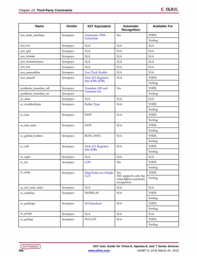
Chapter 14: Thir d-Party Constraints
Name Vendor XST Equiv alent AutomaticRecognition
Availab le For
VHDLsyn_state_machine Synopsys Automatic FSMExtraction
Yes
Verilog
syn_tco Synopsys N/A N/A N/A
syn_tpd Synopsys N/A N/A N/A
syn_tristate Synopsys N/A N/A N/A
syn_tristatetomux Synopsys N/A N/A N/A
syn_tsu Synopsys N/A N/A N/A
syn_useenables Synopsys Use Clock Enable N/A N/A
VHDLsyn_useioff Synopsys Pack I/O RegistersInto IOBs (IOB)
N/A
Verilog
synthesis_translate_off Synopsys VHDL
synthesis_translate_on Synopsys
Translate Off andTranslate On
Yes
Verilog
xc_alias Synopsys N/A N/A N/A
VHDLxc_clockbuftype Synopsys Buffer Type N/A
Verilog
VHDLxc_fast Synopsys FAST N/A
Verilog
VHDLxc_fast_auto Synopsys FAST N/A
Verilog
VHDLxc_global_buffers Synopsys BUFG (XST) N/A
Verilog
VHDLxc_ioff Synopsys Pack I/O RegistersInto IOBs
N/A
Verilog
xc_isgsr Synopsys N/A N/A N/A
VHDLxc_loc Synopsys LOC Yes
Verilog
VHDLxc_map Synopsys Map Entity on a SingleLUT
YesXST supports only thevalue lut for automaticrecognition.
Verilog
xc_ncf_auto_relax Synopsys N/A N/A N/A
VHDLxc_nodelay Synopsys NODELAY N/A
Verilog
VHDLxc_padtype Synopsys I/O Standard N/A
Verilogxc_props Synopsys N/A N/A N/A
VHDLxc_pullup Synopsys PULLUP N/A
Verilog
XST User Guide for Vir tex-6, Spar tan-6, and 7 Series Devices466 www.xilinx.com UG687 (v 14.5) March 20, 2013
Send Feedback

Chapter 14: Thir d-Party Constraints
Name Vendor XST Equiv alent AutomaticRecognition
Availab le For
VHDLxc_rloc Synopsys RLOC Yes
Verilog
VHDLxc_fast Synopsys FAST N/A
Verilog
xc_slow Synopsys N/A N/A N/A
VHDLxc_uset Synopsys U_SET Yes
Verilog
XST User Guide for Vir tex-6, Spar tan-6, and 7 Series DevicesUG687 (v 14.5) March 20, 2013 www.xilinx.com 467
Send Feedback

XST User Guide for Vir tex-6, Spar tan-6, and 7 Series Devices468 www.xilinx.com UG687 (v 14.5) March 20, 2013
Send Feedback

Chapter 15
Synthesis Report• The Synthesis Report:
– Is an ASCII text file.
– Is a hybrid between a report and a log.
– Contains information about the XST synthesis run.
• During synthesis, the Synthesis Report allows you to:
– Control the progress of the synthesis.
– Review preliminary synthesis results.
• After synthesis, the Synthesis Report allows you to determine whether:
– The HDL description has been processed according to expectations.
– Device resource utilization and optimization levels will meet design goals oncethe synthesized netlist has been run through the implementation chain.
Synthesis Repor t ContentThe Synthesis Report contains the following sections:
• Table of Contents
• Synthesis Options Summary
• HDL Parsing and Elaboration
• HDL Synthesis
• Advanced HDL Synthesis
• Low Level Synthesis
• Partition Report
• Design Summary
Table of ContentsUse the Table of Contents to navigate through the Synthesis Report. For moreinformation, see Synthesis Report Navigation.
Synthesis Options Summar yThe Synthesis Options Summary summarizes the parameters and options used forthe current synthesis run.
XST User Guide for Vir tex-6, Spar tan-6, and 7 Series DevicesUG687 (v 14.5) March 20, 2013 www.xilinx.com 469
Send Feedback

Chapter 15: Synthesis Repor t
HDL Parsing and ElaborationDuring HDL parsing and elaboration, XST:• Parses the VHDL and Verilog files that make up the synthesis project.• Interprets the content of those files.• Recognizes the design hierarchy.• Flags HDL coding mistakes.• Points out potential problems such as:
– Simulation mismatches between post-synthesis and HDL.– Potential multi-source situations.
If problems occur at later stages of synthesis, the HDL parsing and elaboration sectionsmay reveal the root cause of these problems.
HDL SynthesisDuring HDL Synthesis:• XST attempts to recognize basic macros for which a technology-specific
implementation might later be possible. These basic macros include:– Registers– Adders– Multipliers
• XST looks for Finite State Machine (FSM) descriptions on a block by block basis.• XST issues the HDL Synthesis Report, which provides statistics on inferred macros.
For more information about macro processing and the messages issued during synthesis,see Chapter 7, HDL Coding Techniques.
Advanced HDL SynthesisDuring Advanced HDL Synthesis, XST attempts to combine basic macros inferredduring HDL Synthesis into larger macro blocks.• The macro blocks include:
– Counters– Pipelined Multipliers– Multiply-Accumulate functions
• XST reports on the selected encoding scheme for each inferred Finite State Machine(FSM).
• The Advanced HDL Synthesis Report summarizes the recognized macros in theoverall design.
• The recognized macros are sorted by macro type.
For more information, see Chapter 7, Coding Techniques.
Low Level SynthesisThe Low Level Synthesis section displays information about XST low-leveloptimizations, including:• Removal of equivalent Flip-Flops• Optimization of constant Flip-Flops• Register replication
XST User Guide for Vir tex-6, Spar tan-6, and 7 Series Devices470 www.xilinx.com UG687 (v 14.5) March 20, 2013
Send Feedback
Chapter 15: Synthesis Repor t
Partition Repor tThe Partition Report displays information about the design partitions.
Design Summar yThe Design Summary section helps you determine whether:• Synthesis has been successful.• Device utilization and circuit performance have met design goals.
The Design Summary section contains the following subsections:• Primitive and Black Box Usage• Device Utilization Summary• Partition Resource Summary• Timing Report• Clock Information• Asynchronous Control Signals Information• Timing Summary• Timing Details• Encrypted Modules
Primitive and Black Box UsageThe Primitive and Black Box Usage subsection displays usage statistics for:• Device primitives• Identified Black Boxes
The primitives are classified in the following groups:• BELs
All basic logical primitives such as LUT, MUXCY, XORCY, MUXF5, and MUXF6• Flip-Flops and Latches• Block and distributed RAM• Shift Register primitives• Tristate buffers• Clock buffers• I/O buffers• Other logical, more complex, primitives such as AND2 and OR2• Other primitives
Device Utilization Summar yThe Device Utilization Summary displays device utilization estimates for:• Slice logic utilization• Slice logic distribution• Number of Flip-Flops• I/O utilization• Number of block RAM components• Number of DSP blocks
XST generates a similar report when you later run MAP.
XST User Guide for Vir tex-6, Spar tan-6, and 7 Series DevicesUG687 (v 14.5) March 20, 2013 www.xilinx.com 471
Send Feedback
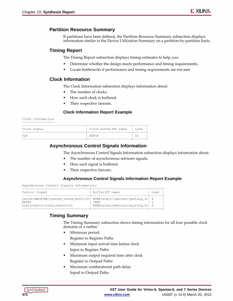
Chapter 15: Synthesis Repor t
Partition Resour ce Summar yIf partitions have been defined, the Partition Resource Summary subsection displaysinformation similar to the Device Utilization Summary on a partition-by-partition basis.
Timing Repor tThe Timing Report subsection displays timing estimates to help you:
• Determine whether the design meets performance and timing requirements.• Locate bottlenecks if performance and timing requirements are not met.
Clock InformationThe Clock Information subsection displays information about:• The number of clocks.• How each clock is buffered.• Their respective fanouts.
Clock Information Repor t ExampleClock Information:-----------------------------------------------------+------------------------+-------+Clock Signal | Clock buffer(FF name) | Load |-----------------------------------+------------------------+-------+CLK | BUFGP | 11 |-----------------------------------+------------------------+-------+
Async hronous Contr ol Signals InformationThe Asynchronous Control Signals Information subsection displays information about:• The number of asynchronous set/reset signals.• How each signal is buffered.• Their respective fanouts.
Async hronous Contr ol Signals Information Repor t ExampleAsynchronous Control Signals Information:-------------------------------------+-------------------------------+-------+Control Signal | Buffer(FF name) | Load |-------------------------------------+-------------------------------+-------+rstint(MACHINE/current_state_Out01:O)| NONE(sixty/lsbcount/qoutsig_3)| 4 |RESET | IBUF | 3 |sixty/msbclr(sixty/msbclr:O) | NONE(sixty/msbcount/qoutsig_3)| 4 |-------------------------------------+-------------------------------+-------+
Timing Summar yThe Timing Summary subsection shows timing information for all four possible clockdomains of a netlist:• Minimum period
Register to Register Paths• Minimum input arrival time before clock
Input to Register Paths• Maximum output required time after clock
Register to Outpad Paths• Maximum combinatorial path delay
Inpad to Outpad Paths
XST User Guide for Vir tex-6, Spar tan-6, and 7 Series Devices472 www.xilinx.com UG687 (v 14.5) March 20, 2013
Send Feedback

Chapter 15: Synthesis Repor t
This timing information is an estimate. For precise timing information, see the TRACEReport generated after placement and routing.
Timing Summar y Repor t ExampleTiming Summary:---------------Speed Grade: -1
Minimum period: 2.644ns (Maximum Frequency: 378.165MHz)Minimum input arrival time before clock: 2.148nsMaximum output required time after clock: 4.803nsMaximum combinatorial path delay: 4.473ns
Timing DetailsThe Timing Details subsection displays information about the most critical path in eachclock region. The information includes:• Start point• End point• Maximum delay• Levels of logic• Detailed breakdown of the path into individual net and component delays• Information on net fanouts• Distribution between routing and logic
Detailed Path Breakdo wnIn some cases, XST writes out a hierarchical netlist with Netlist Hierarchy in which thereported path crosses hierarchical boundaries.
In that event, the detailed path breakdown uses the begin scope and end scopekeywords to indicate when the path enters and exits a hierarchical block.
Timing Details Repor t ExampleTiming Details:---------------All values displayed in nanoseconds (ns)
=========================================================================Timing constraint: Default period analysis for Clock ’CLK’Clock period: 2.644ns (frequency: 378.165MHz)Total number of paths / destination ports: 77 / 11
-------------------------------------------------------------------------Delay: 2.644ns (Levels of Logic = 3)Source: MACHINE/current_state_FFd3 (FF)Destination: sixty/msbcount/qoutsig_3 (FF)Source Clock: CLK risingDestination Clock: CLK rising
Data Path: MACHINE/current_state_FFd3 to sixty/msbcount/qoutsig_3Gate Net
Cell:in->out fanout Delay Delay Logical Name (Net Name)---------------------------------------- ------------FDC:C->Q 8 0.272 0.642 ctrl/state_FFd3 (ctrl/state_FFd3)LUT3:I0->O 3 0.147 0.541 Ker81 (clkenable)LUT4_D:I1->O 1 0.147 0.451 sixty/msbce (sixty/msbce)LUT3:I2->O 1 0.147 0.000 sixty/msbcount/qoutsig_3_rstpot (N43)FDC:D 0.297 sixty/msbcount/qoutsig_3----------------------------------------Total 2.644ns (1.010ns logic, 1.634ns route)
(38.2% logic, 61.8% route)
XST User Guide for Vir tex-6, Spar tan-6, and 7 Series DevicesUG687 (v 14.5) March 20, 2013 www.xilinx.com 473
Send Feedback

Chapter 15: Synthesis Repor t
Timing Constraint Default Path Anal ysis Repor t ExampleTiming constraint: Default path analysisTotal number of paths / destination ports: 36512 / 16
-------------------------------------------------------------------------Delay: 4.326ns (Levels of Logic = 14)Source: a<0> (PAD)Destination: out<3> (PAD)
Data Path: a<0> to out<>Gate Net
Cell:in->out fanout Delay Delay Logical Name (Net Name)---------------------------------------- ------------IBUF:I->O 5 0.003 0.376 a_0_IBUF (a_0_IBUF)begin scope: ’m’begin scope: ’a1’LUT2:I0->O 1 0.053 0.000 Madd_out_Madd_lut<0> (Madd_out_Madd_lut<0>)MUXCY:S->O 1 0.219 0.000 Madd_out_Madd_cy<0> (Madd_out_Madd_cy<0>)MUXCY:CI->O 1 0.015 0.000 Madd_out_Madd_cy<1> (Madd_out_Madd_cy<1>)MUXCY:CI->O 1 0.015 0.000 Madd_out_Madd_cy<2> (Madd_out_Madd_cy<2>)MUXCY:CI->O 1 0.015 0.000 Madd_out_Madd_cy<3> (Madd_out_Madd_cy<3>)MUXCY:CI->O 1 0.015 0.000 Madd_out_Madd_cy<4> (Madd_out_Madd_cy<4>)MUXCY:CI->O 1 0.015 0.000 Madd_out_Madd_cy<5> (Madd_out_Madd_cy<5>)MUXCY:CI->O 0 0.015 0.000 Madd_out_Madd_cy<6> (Madd_out_Madd_cy<6>)XORCY:CI->O 1 0.180 0.279 Madd_out_Madd_xor<7> (out<7>)end scope: ’a1’DSP48E1:A7->P2 1 2.843 0.279 Maddsub_out (out_2_OBUF)end scope: ’m’OBUF:I->O 0.003 out_2_OBUF (out<2>)----------------------------------------Total 4.326ns (3.391ns logic, 0.935ns route)
(78.4% logic, 21.6% route)
Obtaining Cross Clock Domain Timing Information• The Cross Domains Crossing Report section:
– Reports Clock Domain Crossing (CDC) paths.
– Is included by default.
– Follows the Timing Details section.
– Is available whether or not XST has performed cross clock domain optimization.
– Is available whether or not you have specified timing constraints in an XSTConstraint File (XCF).
• You do not need to enable Cross Clock Analysis to obtain cross clock domain timinginformation.
• Use Cross Clock Analysis only in order to achieve timing optimizations across clockdomains.
XST User Guide for Vir tex-6, Spar tan-6, and 7 Series Devices474 www.xilinx.com UG687 (v 14.5) March 20, 2013
Send Feedback

Chapter 15: Synthesis Repor t
Cross Domains Crossing Repor t ExampleClock Domains Crossing Report:-----------------------------
Clock to Setup on destination clock clk2---------------+---------+---------+---------+---------+
| Src:Rise| Src:Fall| Src:Rise| Src:Fall|Source Clock |Dest:Rise|Dest:Rise|Dest:Fall|Dest:Fall|---------------+---------+---------+---------+---------+clk1 | 0.804| | | |clk2 | 0.661| | | |---------------+---------+---------+---------+---------+
Clock to Setup on destination clock clk3---------------+---------+---------+---------+---------+
| Src:Rise| Src:Fall| Src:Rise| Src:Fall|Source Clock |Dest:Rise|Dest:Rise|Dest:Fall|Dest:Fall|---------------+---------+---------+---------+---------+clk2 | | | 0.809| |clk3 | | | 0.651| |---------------+---------+---------+---------+---------+
Encr ypted ModulesXST hides all information about encrypted modules.
XST User Guide for Vir tex-6, Spar tan-6, and 7 Series DevicesUG687 (v 14.5) March 20, 2013 www.xilinx.com 475
Send Feedback
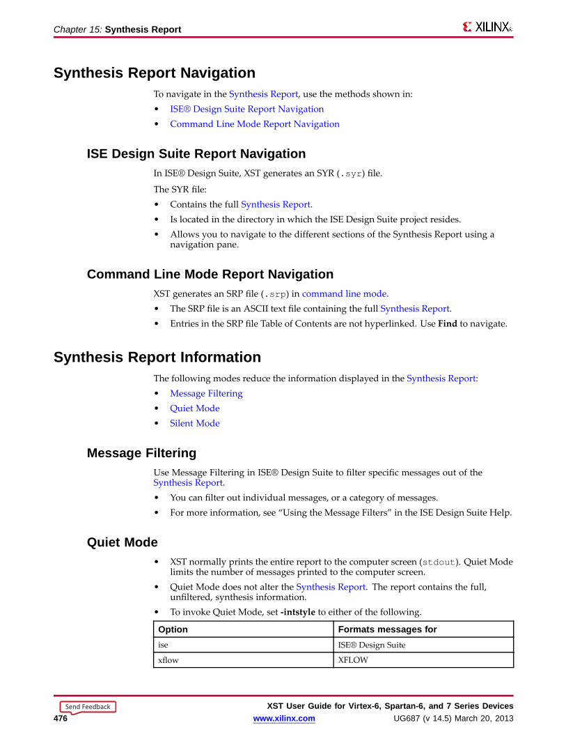
Chapter 15: Synthesis Repor t
Synthesis Repor t NavigationTo navigate in the Synthesis Report, use the methods shown in:• ISE® Design Suite Report Navigation• Command Line Mode Report Navigation
ISE Design Suite Repor t NavigationIn ISE® Design Suite, XST generates an SYR (.syr ) file.
The SYR file:• Contains the full Synthesis Report.• Is located in the directory in which the ISE Design Suite project resides.• Allows you to navigate to the different sections of the Synthesis Report using a
navigation pane.
Command Line Mode Repor t NavigationXST generates an SRP file (.srp ) in command line mode.• The SRP file is an ASCII text file containing the full Synthesis Report.• Entries in the SRP file Table of Contents are not hyperlinked. Use Find to navigate.
Synthesis Repor t InformationThe following modes reduce the information displayed in the Synthesis Report:• Message Filtering• Quiet Mode• Silent Mode
Message FilteringUse Message Filtering in ISE® Design Suite to filter specific messages out of theSynthesis Report.• You can filter out individual messages, or a category of messages.• For more information, see “Using the Message Filters” in the ISE Design Suite Help.
Quiet Mode• XST normally prints the entire report to the computer screen (stdout ). Quiet Mode
limits the number of messages printed to the computer screen.• Quiet Mode does not alter the Synthesis Report. The report contains the full,
unfiltered, synthesis information.• To invoke Quiet Mode, set -intstyle to either of the following.
Option Formats messages forise ISE® Design Suite
xflow XFLOW
XST User Guide for Vir tex-6, Spar tan-6, and 7 Series Devices476 www.xilinx.com UG687 (v 14.5) March 20, 2013
Send Feedback

Chapter 15: Synthesis Repor t
Repor t Sections Printed to the Computer ScreenIn Quiet Mode, XST prints the following sections of the Synthesis Report to the computerscreen.
• Device Utilization Summary
• Clock Information
• Timing Summary
Repor t Sections NOT Printed to the Computer ScreenIn Quiet Mode, XST does NOT print the following sections of the Synthesis Reportto the computer screen.
• Copyright Message
• Table of Contents
• Synthesis Options Summary
• The following portions of the Design Summary:
– Final Results section
– A note stating that the timing numbers are only a synthesis estimate
– Timing Details
– CPU (XST runtime)
– Memory usage
Silent ModeSilent Mode prevents messages from being sent to the computer screen (stdout ).
• The Synthesis Report is written to the log file.
• To invoke Silent Mode, set -intstyle to silent.
XST User Guide for Vir tex-6, Spar tan-6, and 7 Series DevicesUG687 (v 14.5) March 20, 2013 www.xilinx.com 477
Send Feedback

XST User Guide for Vir tex-6, Spar tan-6, and 7 Series Devices478 www.xilinx.com UG687 (v 14.5) March 20, 2013
Send Feedback

Chapter 16
Naming ConventionsSynthesis tools must use naming conventions for objects written to the synthesizednetlist.• The naming conventions must be:
– Logical– Consistent– Predictable– Repeatable
• Naming conventions help you:– Control implementation of a design with constraints.– Reduce timing closure cycles.
Naming Conventions Coding ExamplesFor update information, see “Coding Examples” in the Introduction.
Reg in Labeled Always Bloc k Verilog Coding Example//// A reg in a labelled always block//// Download: http://www.xilinx.com/txpatches/pub/documentation/misc/xstug_examples.zip// File: Naming_Conventions/reg_in_labelled_always.v//module top (
input clk,input di,output do
);
reg data;
always @(posedge clk)begin : mylabel
reg tmp;
tmp <= di; // Post-synthesis name : mylabel.tmpdata <= ~tmp; // Post-synthesis name : data
end
assign do = ~data;
endmodule
XST User Guide for Vir tex-6, Spar tan-6, and 7 Series DevicesUG687 (v 14.5) March 20, 2013 www.xilinx.com 479
Send Feedback

Chapter 16: Naming Conventions
Primitive Instantiation in If-Generate Without Label Verilog CodingExample
//// A primitive instantiation in a if-generate without label//// Download: http://www.xilinx.com/txpatches/pub/documentation/misc/xstug_examples.zip// File: Naming_Conventions/if_generate_nolabel.v//module top (
input clk,input di,output do
);
parameter TEST_COND= 1;
generate
if (TEST_COND) beginFD myinst (.C(clk), .D(di), .Q(do)); // Post-synthesis name : myinst
end
endgenerate
endmodule
Primitive Instantiation in If-Generate With Label Verilog CodingExample
//// A primitive instantiation in a labelled if-generate//// Download: http://www.xilinx.com/txpatches/pub/documentation/misc/xstug_examples.zip// File: Naming_Conventions/if_generate_label.v//module top (
input clk,input rst,input di,output do
);
// parameter TEST_COND= 1;parameter TEST_COND= 0;
generate
if (TEST_COND)begin : myifname
FDR myinst (.C(clk), .D(di), .Q(do), .R(rst));// Post-synthesis name : myifname.myinst
endelse
begin : myelsenameFDS myinst (.C(clk), .D(di), .Q(do), .S(rst));
// Post-synthesis name : myelsename.myinstend
endgenerate
endmodule
XST User Guide for Vir tex-6, Spar tan-6, and 7 Series Devices480 www.xilinx.com UG687 (v 14.5) March 20, 2013
Send Feedback

Chapter 16: Naming Conventions
Variab le in Labeled Process VHDL Coding Example---- A variable in a labelled process---- Download: http://www.xilinx.com/txpatches/pub/documentation/misc/xstug_examples.zip-- File: Naming_Conventions/var_in_labelled_process.vhd--library ieee;use ieee.std_logic_1164.all;
entity top isport(
clk : in std_logic;di : in std_logic;
do : out std_logic);
end top;
architecture behavioral of top issignal data : std_logic;
begin
mylabel: process (clk)variable tmp : std_logic;
beginif rising_edge(clk) then
tmp := di; -- Post-synthesis name : mylabel.tmpend if;data <= not(tmp);
end process;
do <= not(data);
end behavioral;
Flip-Flop Modeled With a Boolean VHDL Coding Example---- Naming of boolean type objects---- Download: http://www.xilinx.com/txpatches/pub/documentation/misc/xstug_examples.zip-- File: Naming_Conventions/boolean.vhd--library ieee;use ieee.std_logic_1164.all;
entity top isport(
clk : in std_logic;di : in boolean;
do : out boolean);
end top;
architecture behavioral of top issignal data : boolean;
begin
process (clk)begin
if rising_edge(clk) thendata <= di; -- Post-synthesis name : data
end if;end process;
do <= not(data);
end behavioral;
XST User Guide for Vir tex-6, Spar tan-6, and 7 Series DevicesUG687 (v 14.5) March 20, 2013 www.xilinx.com 481
Send Feedback
Chapter 16: Naming Conventions
Net Naming ConventionsXST creates net names based on the following rules, listed in order of naming priority.
1. Maintain external pin names.
2. Keep hierarchy in signal names.
Use the hierarchy separator defined by Hierarchy Separator. The default hierarchyseparator is a forward slash (/).
3. Maintain output signal names of registers, including state bits.
Use the hierarchical name from the level in which the register was inferred.
4. For output signals of clock buffers, a _clockbuffertype suffix (such as _BUFGP or_IBUFG) is appended to the clock signal name.
5. Maintain input nets to registers and tristates names.
6. Maintain names of signals connected to primitives and black boxes.
7. The output net of an IBUF is named <signal_name>_IBUF.
For example, if an IBUF output drives signal DIN, the output net of this IBUF isnamed DIN_IBUF.
8. The input net to an OBUF is named <signal_name>_OBUF.
For example, if an OBUF input is driven by signal DOUT, the input net of this OBUFis named DOUT_OBUF.
9. Base names for internal (combinatorial) nets on user HDL signal names wherepossible.
10. Nets resulting from the expansion of buses are formatted as:
<bus_name><left_delimiter><position>#<right_delimiter>.
• The default left and right delimiters are respectively < and >.
• Use Bus Delimiter to change this convention.
XST User Guide for Vir tex-6, Spar tan-6, and 7 Series Devices482 www.xilinx.com UG687 (v 14.5) March 20, 2013
Send Feedback

Chapter 16: Naming Conventions
Instance Naming ConventionsXST creates instance names based on the following rules, listed in order of namingpriority:
1. Maintain hierarchy in instance names.
• Use the hierarchy separator defined by Hierarchy Separator.
• The default hierarchy separator is a slash (/).2. When instance names are generated from HDL generate statements, labels from the
generate statements are used in composition of instance names.• For the following VHDL generate statement:
i1_loop: for i in 1 to 10 generateinst_lut:LUT2 generic map (INIT => "00")
• XST generates the following instance names for LUT2:
i1_loop[1].inst_luti1_loop[2].inst_lut...i1_loop[9].inst_luti1_loop[10].inst_lut
3. Match the Flip-Flop instance name to the name of the signal it drives. This principlealso applies to state bits.
4. Name clock buffer instances _clockbuffertype (such as _BUFGP or _IBUFG) afterthe output signal.
5. Names of Black Box instances are maintained.
6. Names of library primitive instances are maintained.
7. Name input and output buffers using the form _IBUF or _OBUF after the pad name.8. Name output instance names of IBUF elements using the form instance_name_IBUF.9. Name input instance names ofOBUF elements using the form instance_name_OBUF.
Case Preser vation• This section discusses XST case preservation in Verilog and VHDL.
• For more information, see Case Sensitivity.
VHDL (Case Insensitive)• VHDL is case insensitive.
• XST converts object names based on names defined in the HDL source code toall lowercase in the synthesized netlist, unless instructed otherwise by the Casecommand line option.
Verilog (Case Sensitive)• Verilog is case sensitive.
• XST enforces the exact capitalization found in the HDL source code, unlessinstructed otherwise by the Case command line option.
XST User Guide for Vir tex-6, Spar tan-6, and 7 Series DevicesUG687 (v 14.5) March 20, 2013 www.xilinx.com 483
Send Feedback

Chapter 16: Naming Conventions
Name Generation Contr ol• The following constraints permit some control over the naming of objects in the
synthesized netlist.
– Hierarchy Separator
– Bus Delimiter
– Case
– Duplication Suffix
• Apply these constraints in either:
– ISE® Design Suite
Synthesize - XST Process > Properties
– Command Line
• For more information, see Chapter 9, Design Constraints.
XST User Guide for Vir tex-6, Spar tan-6, and 7 Series Devices484 www.xilinx.com UG687 (v 14.5) March 20, 2013
Send Feedback
Appendix
Additional Resources• Xilinx Global Glossary,
http://www.xilinx.com/support/documentation/sw_manuals/glossary.pdf
• Xilinx® Support, http://www.xilinx.com/support
• For more information about XST, see Xilinx® Synthesis Technology (XST) - FrequentlyAsked Questions (FAQ).
• For more information about DSP block resources, see:
– Virtex®-6 FPGA DSP48E1 Slice User Guide (UG369)
– Spartan®-6 FPGA DSP48A1 Slice User Guide (UG389)
– 7 Series DSP48E1 Slice User Guide (UG479)
XST User Guide for Vir tex-6, Spar tan-6, and 7 Series DevicesUG687 (v 14.5) March 20, 2013 www.xilinx.com 485
Send Feedback