sparc enterprise oracle vm server for sparc guideoracle vm server for sparc. guide . c120-e534-15en...
TRANSCRIPT
SPARC Enterprise Oracle VM Server for SPARC
Guide
C120-E534-15EN October 2012

Copyright © 2007, 2012, Oracle and/or its affiliates and FUJITSU LIMITED. All rights reserved. Oracle and/or its affiliates and Fujitsu Limited each own or control intellectual property rights relating to products and technology described in this document, and such products, technology and this document are protected by copyright laws, patents, and other intellectual property laws and international treaties. This document and the product and technology to which it pertains are distributed under licenses restricting their use, copying, distribution, and decompilation. No part of such product or technology, or of this document, may be reproduced in any form by any means without prior written authorization of Oracle and/or its affiliates and Fujitsu Limited, and their applicable licensors, if any. The furnishings of this document to you does not give you any rights or licenses, express or implied, with respect to the product or technology to which it pertains, and this document does not contain or represent any commitment of any kind on the part of Oracle or Fujitsu Limited, or any affiliate of either of them. This document and the product and technology described in this document may incorporate third-party intellectual property copyrighted by and/or licensed from the suppliers to Oracle and/or its affiliates and Fujitsu Limited, including software and font technology. Per the terms of the GPL or LGPL, a copy of the source code governed by the GPL or LGPL, as applicable, is available upon request by the End User. Please contact Oracle and/or its affiliates or Fujitsu Limited. This distribution may include materials developed by third parties. Parts of the product may be derived from Berkeley BSD systems, licensed from the University of California. UNIX is a registered trademark in the U.S. and in other countries, exclusively licensed through X/Open Company, Ltd. Oracle and Java are registered trademarks of Oracle and/or its affiliates. Other names may be trademarks of their respective owners. Fujitsu and the Fujitsu logo are registered trademarks of Fujitsu Limited. All SPARC trademarks are used under license and are registered trademarks of SPARC International, Inc. in the U.S. and other countries. United States Government Rights - Commercial use. U.S. Government users are subject to the standard government user license agreements of Oracle and/or its affiliates and Fujitsu Limited and the applicable provisions of the FAR and its supplements. Disclaimer: The only warranties granted by Oracle and Fujitsu Limited, and/or any affiliate of either of them in connection with this document or any product or technology described herein are those expressly set forth in the license agreement pursuant to which the product or technology is provided. EXCEPT AS EXPRESSLY SET FORTH IN SUCH AGREEMENT, ORACLE OR FUJITSU LIMITED, AND/OR THEIR AFFILIATES MAKE NO REPRESENTATIONS OR WARRANTIES OF ANY KIND (EXPRESS OR IMPLIED) REGARDING SUCH PRODUCT OR TECHNOLOGY OR THIS DOCUMENT, WHICH ARE ALL PROVIDED AS IS, AND ALL EXPRESS OR IMPLIED CONDITIONS, REPRESENTATIONS AND WARRANTIES, INCLUDING WITHOUT LIMITATION ANY IMPLIED WARRANTY OF MERCHANTABILITY, FITNESS FOR A PARTICULAR PURPOSE OR NONINFRINGEMENT, ARE DISCLAIMED, EXCEPT TO THE EXTENT THAT SUCH DISCLAIMERS ARE HELD TO BE LEGALLY INVALID. Unless otherwise expressly set forth in such agreement, to the extent allowed by applicable law, in no event shall Oracle or Fujitsu Limited, and/or any of their affiliates have any liability to any third party under any legal theory for any loss of revenues or profits, loss of use or data, or business interruptions, or for any indirect, special, incidental or consequential damages, even if advised of the possibility of such damages.
DOCUMENTATION IS PROVIDED "AS IS" AND ALL EXPRESS OR IMPLIED CONDITIONS, REPRESENTATIONS AND WARRANTIES, INCLUDING ANY IMPLIED WARRANTY OF MERCHANTABILITY, FITNESS FOR A PARTICULAR PURPOSE OR NON-INFRINGEMENT, ARE DISCLAIMED, EXCEPT TO THE EXTENT THAT SUCH DISCLAIMERS ARE HELD TO BE LEGALLY INVALID.
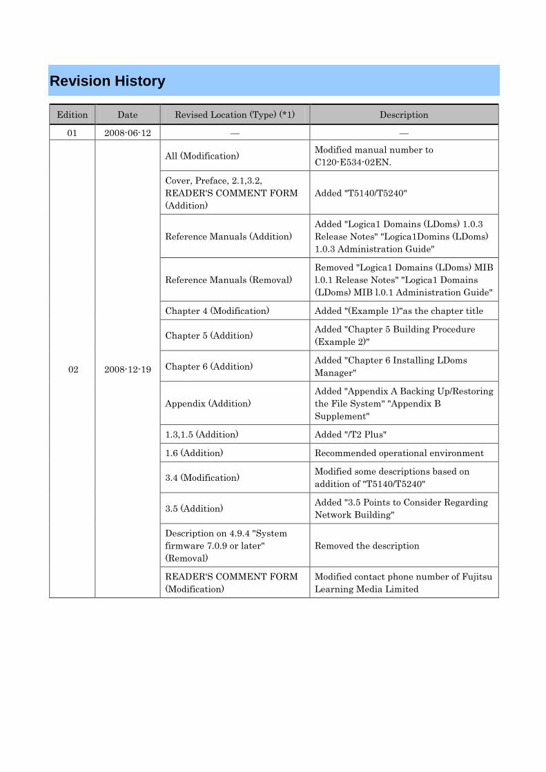
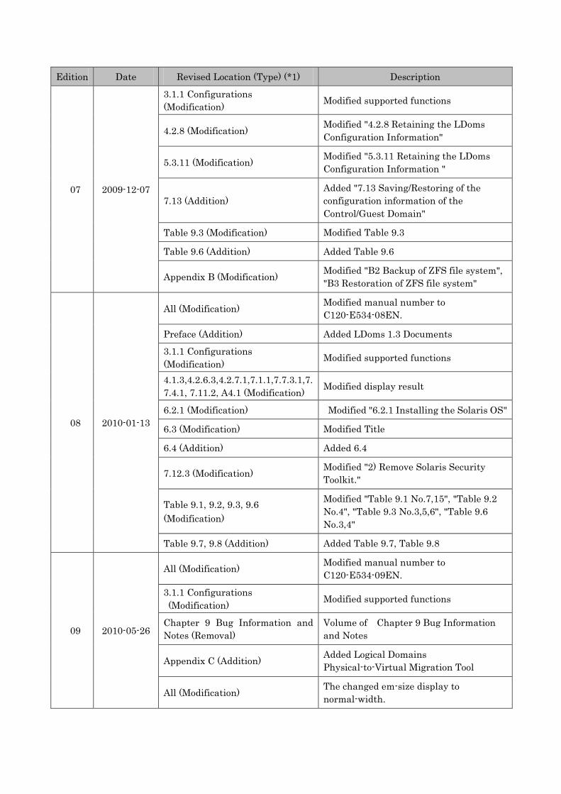
Revision History
Edition Date Revised Location (Type) (*1) Description
01 2008-06-12 — —
02 2008-12-19
All (Modification) Modified manual number to C120-E534-02EN.
Cover, Preface, 2.1,3.2, READER'S COMMENT FORM (Addition)
Added "T5140/T5240"
Reference Manuals (Addition) Added "Logica1 Domains (LDoms) 1.0.3 Release Notes" "Logica1Domins (LDoms) 1.0.3 Administration Guide"
Reference Manuals (Removal) Removed "Logica1 Domains (LDoms) MIB l.0.1 Release Notes" "Logica1 Domains (LDoms) MIB l.0.1 Administration Guide"
Chapter 4 (Modification) Added "(Example 1)"as the chapter title
Chapter 5 (Addition) Added "Chapter 5 Building Procedure (Example 2)"
Chapter 6 (Addition) Added "Chapter 6 Installing LDoms Manager"
Appendix (Addition) Added "Appendix A Backing Up/Restoring the File System" "Appendix B Supplement"
1.3,1.5 (Addition) Added "/T2 Plus"
1.6 (Addition) Recommended operational environment
3.4 (Modification) Modified some descriptions based on addition of "T5140/T5240"
3.5 (Addition) Added "3.5 Points to Consider Regarding Network Building"
Description on 4.9.4 "System firmware 7.0.9 or later" (Removal)
Removed the description
READER'S COMMENT FORM (Modification)
Modified contact phone number of Fujitsu Learning Media Limited
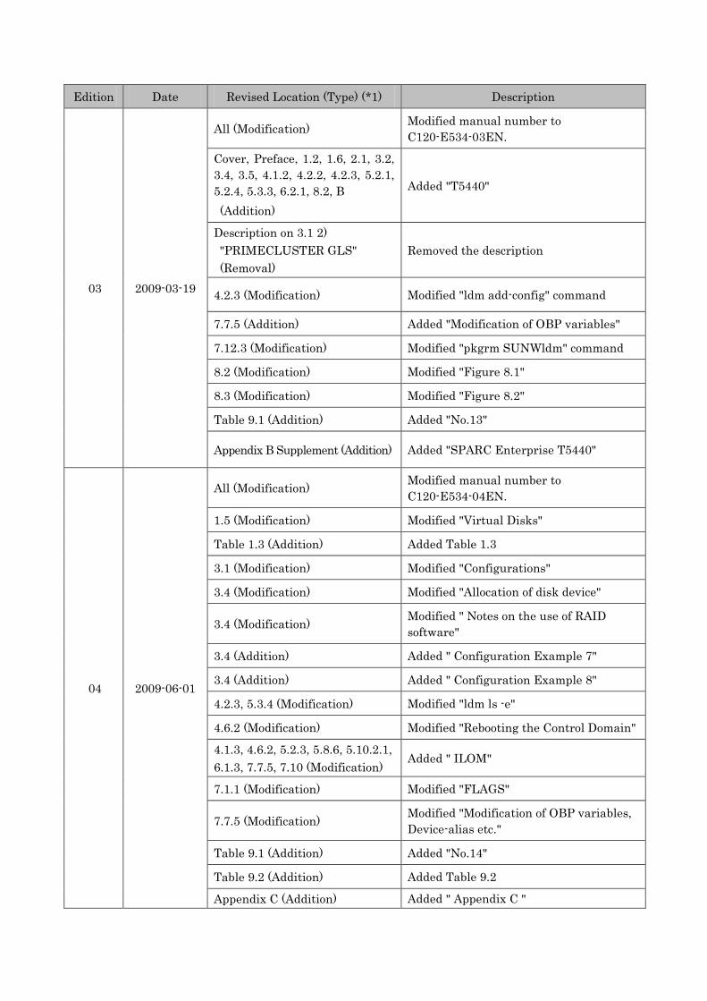
Edition Date Revised Location (Type) (*1) Description
03 2009-03-19
All (Modification) Modified manual number to C120-E534-03EN.
Cover, Preface, 1.2, 1.6, 2.1, 3.2, 3.4, 3.5, 4.1.2, 4.2.2, 4.2.3, 5.2.1, 5.2.4, 5.3.3, 6.2.1, 8.2, B (Addition)
Added "T5440"
Description on 3.1 2) "PRIMECLUSTER GLS" (Removal)
Removed the description
4.2.3 (Modification) Modified "ldm add-config" command
7.7.5 (Addition) Added "Modification of OBP variables"
7.12.3 (Modification) Modified "pkgrm SUNWldm" command
8.2 (Modification) Modified "Figure 8.1"
8.3 (Modification) Modified "Figure 8.2"
Table 9.1 (Addition) Added "No.13"
Appendix B Supplement (Addition) Added "SPARC Enterprise T5440"
04 2009-06-01
All (Modification) Modified manual number to C120-E534-04EN.
1.5 (Modification) Modified "Virtual Disks"
Table 1.3 (Addition) Added Table 1.3
3.1 (Modification) Modified "Configurations"
3.4 (Modification) Modified "Allocation of disk device"
3.4 (Modification) Modified " Notes on the use of RAID software"
3.4 (Addition) Added " Configuration Example 7"
3.4 (Addition) Added " Configuration Example 8"
4.2.3, 5.3.4 (Modification) Modified "ldm ls -e"
4.6.2 (Modification) Modified "Rebooting the Control Domain"
4.1.3, 4.6.2, 5.2.3, 5.8.6, 5.10.2.1, 6.1.3, 7.7.5, 7.10 (Modification)
Added " ILOM"
7.1.1 (Modification) Modified "FLAGS"
7.7.5 (Modification) Modified "Modification of OBP variables, Device-alias etc."
Table 9.1 (Addition) Added "No.14"
Table 9.2 (Addition) Added Table 9.2
Appendix C (Addition) Added " Appendix C "
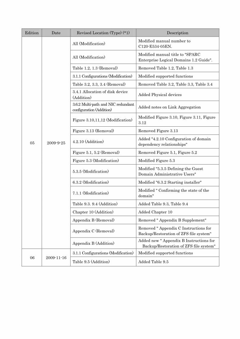
Edition Date Revised Location (Type) (*1) Description
05 2009-9-25
All (Modification) Modified manual number to C120-E534-05EN.
All (Modification) Modified manual title to "SPARC Enterprise Logical Domains 1.2 Guide".
Table 1.2, 1.3 (Removal) Removed Table 1.2, Table 1.3
3.1.1 Configurations (Modification) Modified supported functions
Table 3.2, 3.3, 3.4 (Removal) Removed Table 3.2, Table 3.3, Table 3.4
3.4.1 Allocation of disk device (Addition)
Added Physical devices
3.6.2 Multi-path and NIC redundant configuration (Addition) Added notes on Link Aggregation
Figure 3.10,11,12 (Modification) Modified Figure 3.10, Figure 3.11, Figure 3.12
Figure 3.13 (Removal) Removed Figure 3.13
4.2.10 (Addition) Added "4.2.10 Configuration of domain dependency relationships"
Figure 5.1, 5.2 (Removal) Removed Figure 5.1, Figure 5.2
Figure 5.3 (Modification) Modified Figure 5.3
5.3.5 (Modification) Modified "5.3.5 Defining the Guest Domain Administrative Users"
6.3.2 (Modification) Modified "6.3.2 Starting installer"
7.1.1 (Modification) Modified " Confirming the state of the domain"
Table 9.3. 9.4 (Addition) Added Table 9.3, Table 9.4
Chapter 10 (Addition) Added Chapter 10
Appendix B (Removal) Removed " Appendix B Supplement"
Appendix C (Removal) Removed " Appendix C Instructions for Backup/Restoration of ZFS file system"
Appendix B (Addition) Added new " Appendix B Instructions for Backup/Restoration of ZFS file system"
06 2009-11-16 3.1.1 Configurations (Modification) Modified supported functions
Table 9.5 (Addition) Added Table 9.5
Edition Date Revised Location (Type) (*1) Description
07 2009-12-07
3.1.1 Configurations (Modification) Modified supported functions
4.2.8 (Modification) Modified "4.2.8 Retaining the LDoms Configuration Information"
5.3.11 (Modification) Modified "5.3.11 Retaining the LDoms Configuration Information "
7.13 (Addition) Added "7.13 Saving/Restoring of the configuration information of the Control/Guest Domain"
Table 9.3 (Modification) Modified Table 9.3
Table 9.6 (Addition) Added Table 9.6
Appendix B (Modification) Modified "B2 Backup of ZFS file system", "B3 Restoration of ZFS file system"
08 2010-01-13
All (Modification) Modified manual number to C120-E534-08EN.
Preface (Addition) Added LDoms 1.3 Documents
3.1.1 Configurations (Modification) Modified supported functions
4.1.3,4.2.6.3,4.2.7.1,7.1.1,7.7.3.1,7.7.4.1, 7.11.2, A4.1 (Modification) Modified display result
6.2.1 (Modification) Modified "6.2.1 Installing the Solaris OS"
6.3 (Modification) Modified Title
6.4 (Addition) Added 6.4
7.12.3 (Modification) Modified "2) Remove Solaris Security Toolkit."
Table 9.1, 9.2, 9.3, 9.6 (Modification)
Modified "Table 9.1 No.7,15", "Table 9.2 No.4", "Table 9.3 No.3,5,6", "Table 9.6 No.3,4"
Table 9.7, 9.8 (Addition) Added Table 9.7, Table 9.8
09 2010-05-26
All (Modification) Modified manual number to C120-E534-09EN.
3.1.1 Configurations (Modification) Modified supported functions
Chapter 9 Bug Information and Notes (Removal)
Volume of Chapter 9 Bug Information and Notes
Appendix C (Addition) Added Logical Domains Physical-to-Virtual Migration Tool
All (Modification) The changed em-size display to normal-width.
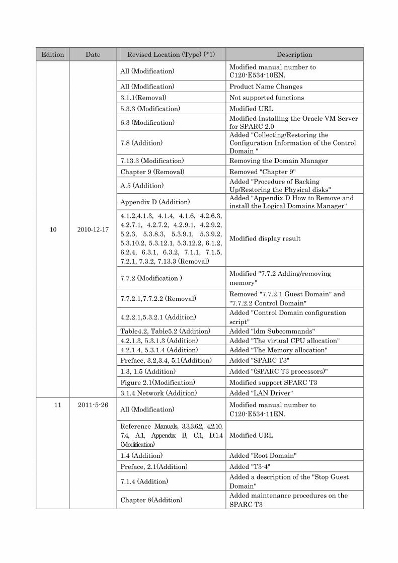
Edition Date Revised Location (Type) (*1) Description
10 2010-12-17
All (Modification) Modified manual number to C120-E534-10EN.
All (Modification) Product Name Changes 3.1.1(Removal) Not supported functions 5.3.3 (Modification) Modified URL
6.3 (Modification) Modified Installing the Oracle VM Server for SPARC 2.0
7.8 (Addition) Added "Collecting/Restoring the Configuration Information of the Control Domain "
7.13.3 (Modification) Removing the Domain Manager Chapter 9 (Removal) Removed "Chapter 9"
A.5 (Addition) Added "Procedure of Backing Up/Restoring the Physical disks"
Appendix D (Addition) Added "Appendix D How to Remove and install the Logical Domains Manager"
4.1.2,4.1.3, 4.1.4, 4.1.6, 4.2.6.3, 4.2.7.1, 4.2.7.2, 4.2.9.1, 4.2.9.2, 5.2.3, 5.3.8.3, 5.3.9.1, 5.3.9.2, 5.3.10.2, 5.3.12.1, 5.3.12.2, 6.1.2, 6.2.4, 6.3.1, 6.3.2, 7.1.1, 7.1.5, 7.2.1, 7.3.2, 7.13.3 (Removal)
Modified display result
7.7.2 (Modification ) Modified "7.7.2 Adding/removing memory"
7.7.2.1,7.7.2.2 (Removal) Removed "7.7.2.1 Guest Domain" and "7.7.2.2 Control Domain"
4.2.2.1,5.3.2.1 (Addition) Added "Control Domain configuration script"
Table4.2, Table5.2 (Addition) Added "ldm Subcommands" 4.2.1.3, 5.3.1.3 (Addition) Added "The virtual CPU allocation" 4.2.1.4, 5.3.1.4 (Addition) Added "The Memory allocation" Preface, 3.2,3.4, 5.1(Addition) Added "SPARC T3" 1.3, 1.5 (Addition) Added "(SPARC T3 processors)" Figure 2.1(Modification) Modified support SPARC T3 3.1.4 Network (Addition) Added "LAN Driver"
11 2011-5-26 All (Modification) Modified manual number to C120-E534-11EN.
Reference Manuals, 3.3,3.6.2, 4.2.10, 7.4, A.1, Appendix B, C.1, D.1.4 (Modification)
Modified URL
1.4 (Addition) Added "Root Domain" Preface, 2.1(Addition) Added "T3-4"
7.1.4 (Addition) Added a description of the "Stop Guest Domain"
Chapter 8(Addition) Added maintenance procedures on the SPARC T3
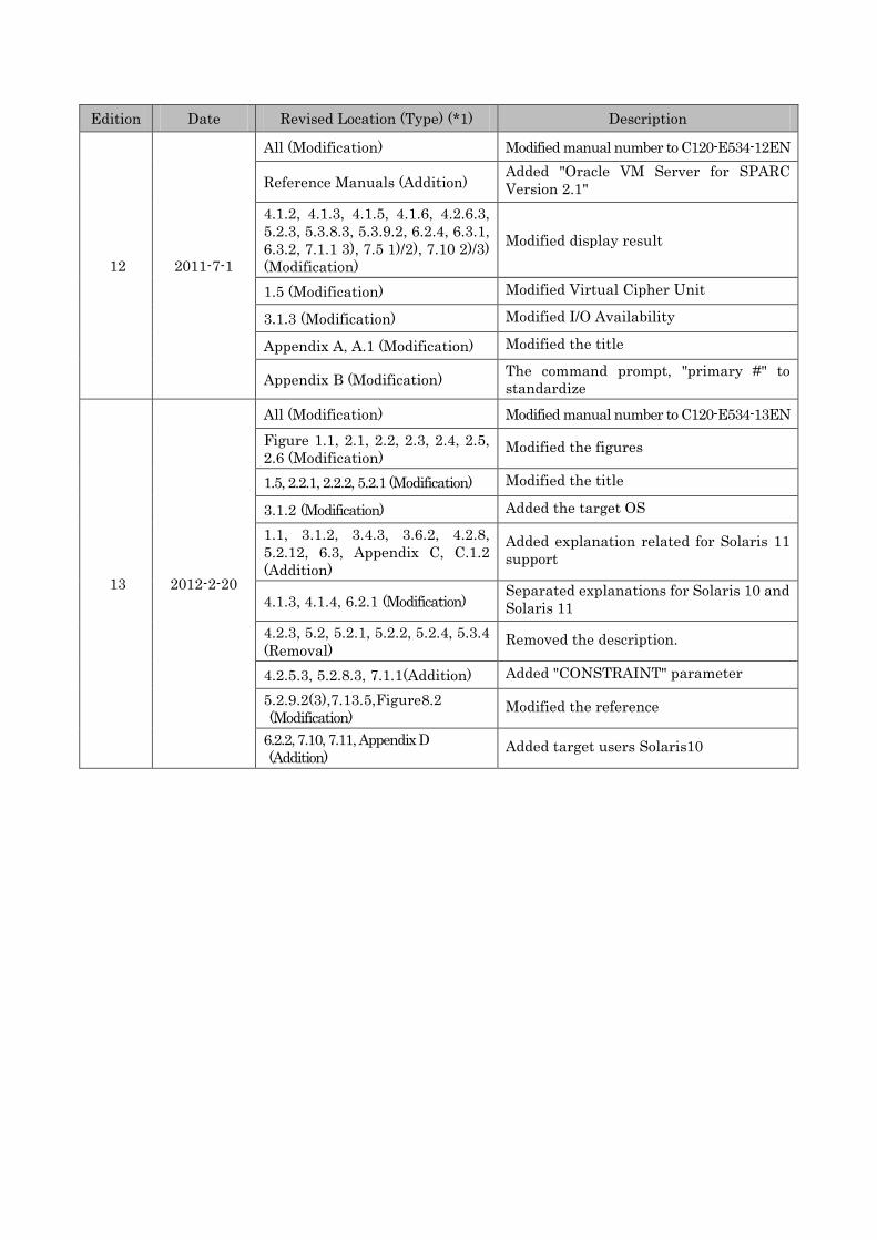
Edition Date Revised Location (Type) (*1) Description
12 2011-7-1
All (Modification) Modified manual number to C120-E534-12EN
Reference Manuals (Addition) Added "Oracle VM Server for SPARC Version 2.1"
4.1.2, 4.1.3, 4.1.5, 4.1.6, 4.2.6.3, 5.2.3, 5.3.8.3, 5.3.9.2, 6.2.4, 6.3.1, 6.3.2, 7.1.1 3), 7.5 1)/2), 7.10 2)/3) (Modification)
Modified display result
1.5 (Modification) Modified Virtual Cipher Unit
3.1.3 (Modification) Modified I/O Availability
Appendix A, A.1 (Modification) Modified the title
Appendix B (Modification) The command prompt, "primary #" to standardize
13 2012-2-20
All (Modification) Modified manual number to C120-E534-13EN Figure 1.1, 2.1, 2.2, 2.3, 2.4, 2.5, 2.6 (Modification)
Modified the figures
1.5, 2.2.1, 2.2.2, 5.2.1 (Modification) Modified the title
3.1.2 (Modification) Added the target OS
1.1, 3.1.2, 3.4.3, 3.6.2, 4.2.8, 5.2.12, 6.3, Appendix C, C.1.2 (Addition)
Added explanation related for Solaris 11 support
4.1.3, 4.1.4, 6.2.1 (Modification) Separated explanations for Solaris 10 and Solaris 11
4.2.3, 5.2, 5.2.1, 5.2.2, 5.2.4, 5.3.4 (Removal)
Removed the description.
4.2.5.3, 5.2.8.3, 7.1.1(Addition) Added "CONSTRAINT" parameter
5.2.9.2(3),7.13.5,Figure8.2 (Modification)
Modified the reference
6.2.2, 7.10, 7.11, Appendix D (Addition)
Added target users Solaris10
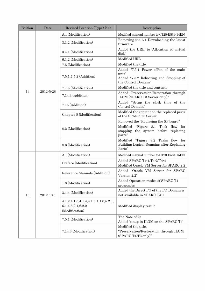
Edition Date Revised Location (Type) (*1) Description
14 2012-5-28
All (Modification) Modified manual number to C120-E534-14EN
3.1.2 (Modification) Removing the 6.1 Downloading the latest firmware
3.4.1 (Modification) Added the URL, to 'Allocation of virtual disk'
6.1.2 (Modification) Modified URL 7.5 (Modification) Modified the title
7.5.1,7.5.2 (Addition)
Added "7.5.1 Power off/on of the main unit” Added "7.5.2 Rebooting and Stopping of the Control Domain"
7.7.5 (Modification) Modified the title and contents
7.14.3 (Addition) Added "Preservation/Restoration through ILOM (SPARC T3 Server only)"
7.15 (Addition) Added "Setup the clock time of the Control Domain"
Chapter 8 (Modification) Modified the content on the replaced parts of the SPARC T3 Server
8.2 (Modification)
Removed the “Replacing the SP board” Modified “Figure 8.1 Task flow for stopping the system before replacing parts”
8.3 (Modification) Modified ”Figure 8.2 Tasks flow for Building Logical Domains after Replacing Parts”
15 2012-10-1
All (Modification) Modified manual number to C120-E534-15EN
Preface (Modification) Added SPARC T4-1/T4-2/T4-4 Modified Oracle VM Server for SPARC 2.2
Reference Manuals (Addition) Added “Oracle VM Server for SPARC Version 2.2”
1.3 (Modification) Added Operation modes of SPARC T4 processors
3.1.4 (Modification) Added the Direct I/O of the I/O Domain is not available in SPARC T4-1
4.1.2,4.1.3,4.1.4,4.1.5,4.1.6,5.2.1, 6.1.4,6.2.1,6.2.2 (Modification)
Modified display result
7.5.1 (Modification) The Note of 2) Added 'setup in ILOM on the SPARC T4'
7.14.3 (Modification) Modified the title. “Preservation/Restoration through ILOM (SPARC T4/T3 only)”
i
Preface
• This document explains the outline, instructions on configuration, operation, etc of Oracle VM Server for SPARC (formerly called Logical Domains or LDoms) provided with SPARC T4-1/T4-2/T4-4 and T3-1/T3-2/T3-4 and SPARC Enterprise T5120/T5220/T5140/T5240/T5440. In this document, Oracle VM Server for SPARC is sometimes described as Logical Domains (LDoms).
• Please refer to "4.1 System requirements for Oracle VM Server for SPARC 2.2" in "SPARC Enterprise Oracle VM Server for SPARC Important Information" about system requirements for Oracle VM Server for SPARC 2.2.
• In this document, an environment created by the Oracle VM Server for SPARC function is described as a domain or Logical Domains.
• This document is supposed to be read by Oracle VM Server for SPARC 2.2 users, but if functions other than ones added by 2.2 are used, this document may be available for customers who are using Oracle VM Server for SPARC 2.1 or older.
• Oracle Solaris might be described as Solaris, Solaris Operating System, or Solaris OS. • This book is compiled for both Oracle Solaris 10 and Oracle Solaris 11. • About Oracle Solaris11 support status, please contact to below.
UNIX Server SPARC Enterprise Feedback https://www-s.fujitsu.com/global/contact/computing/sparce_feedback.html
Or,
SPARC Enterprise contacts http://www.fujitsu.com/global/contact/computing/sparce_index.html
Organization of this manual
This document describes the Logical Domains environment in the following framework.
Chapter 1 Logical Domains This chapter explains an overview of the Logical Domains functions, comparison with other partitioning methods provided by Fujitsu and operations that are appropriate for the Logical Domains environment, for consideration when installing Logical Domains.
Chapter 2 Logical Domains Application This chapter explains purpose and operation appropriate for the Logical Domains and notes on applying the Logical Domains.
Chapter 3 Logical Domains Configuration Design This chapter explains notes on the design or building of Logical Domains environment configuration.
Chapter 4 Building Procedure (Example 1) This chapter explains the building procedure for building the Logical Domains environment.
Chapter 5 Building Procedure (Example 2) This chapter explains the building procedure for building the Logical Domains environment including an I/O domain.
Chapter 6 Installing Logical Domains Manager This chapter explains the procedure for installing Logical Domains Manager.
Chapter 7 Operating Logical Domains This chapter explains the operation method of the Logical Domains environment and notes on operation.
ii
Chapter 8 Tasks Required to Replace Parts This chapter explains the tasks to perform for replacing parts.
Appendix A Backup and Restore Procedure This appendix explains the backup and restores procedures for the Logical Domains.
Appendix B Instructions for Backup/Restoration for ZFS file system This appendix explains backup/restoration of ZFS file system.
Appendix C Logical Domains Physical-to-Virtual Migration Tool This chapter explains the Oracle VM Server for SPARC Physical-to-Virtual Migration Tool.
Appendix D How to Remove and install the Logical Domains Manager This chapter explains Remove and installs the Logical Domains (Logical Domains1.2 or older and Logical Domains 1.3)
Reference Manuals
The documents listed below are documents relating to this manual. Fujitsu has created this document with focus on providing the Logical Domains function, while referring to the Logical Domains (LDoms) Documentation provided by Oracle Corporation. Be sure to read the following documents when building the Logical Domains environment. If you fail to find a manual in Oracle web site, search the relevant manuals in the URL below. http://www.oracle.com/technetwork/indexes/documentation/index.html
Oracle VM Server for SPARC Version 2.2
IMPORTANT INFORMATION FOR THIS RELEASE
• Release Notes ADMINISTERING ORACLE VM SERVER FOR SPARC 2.2
• Administration Guide
ORACLE VM SERVER FOR SPARC REFERENCE • Reference Manual
http://docs.oracle.com/cd/E35434_01/index.html
Functions are not supported/Notes Information/Notes Information/System Requirements/Notes on SPARC T3 /SPARC Enterprise (Official Fujitsu site)
• SPARC Enterprise Oracle VM Server For SPARC Important Information http://www.fujitsu.com/global/services/computing/server/sparcenterprise/products/software/ldoms/
Refer to the following document:
Beginners Guide to Oracle VM Server for SPARC: Understanding and Deploying Logical Domains
http://www.oracle.com/technetwork/articles/systems-hardware-architecture/beginners-vm-server-sparc-256946.pdf
Logical Domains (LDoms) MIB Documentation • Logical Domains (LDoms) MIB 1.0.1 Release Notes • Logical Domains (LDoms) MIB 1.0.1 Administration Guide
http://download.oracle.com/docs/cd/E19053-01/ldoms.mgr10/index.html
iii
Text Conventions
This manual uses the following fonts and symbols to express specific types of information.
Fonts/symbols Meaning Example
AaBbCc Indicates commands that users enter. # ls -l <Enter>
Italic Indicates names of manuals. See the System Console Software User's Guide.
"" Indicates names of chapters, sections, items, buttons, and menus.
See Chapter 4, "Building Procedure."
Syntax of the Command Line Interface (CLI) The command syntax is described below.
Command Syntax
• A variable that requires input of a value must be enclosed in < >. • An optional element must be enclosed in [ ]. • A group of options for an optional keyword must be enclosed in [ ] and delimited by |. • A group of options for a mandatory keyword must be enclosed in { } and delimited by |.
The command syntax is shown in a frame such as this one.
Fujitsu Welcomes Your Comments If you have any comments or requests regarding this document, or if you find any unclear statements in the document, please state your points specifically on the form at the following URL. For Users in U.S.A., Canada, and Mexico: HHHHUUUUhttps://download.computers.us.fujitsu.com/
For Users in Other Countries: HHHHUUUUhttp://www.fujitsu.com/global/contact/computing/sparce_index.html
Notice
The contents of this manual may be revised without prior notice.
iv
Contents
Preface ................................................................................................................................................................ i Organization of this manual ................................................................................................................................. i Reference Manuals ............................................................................................................................................. ii Text Conventions ............................................................................................................................................... iii Command Syntax .............................................................................................................................................. iii Fujitsu Welcomes Your Comments ................................................................................................................... iii
Chapter 1 Logical Domains ....................................................................................................................... 1-1 1.1 The Basics of Logical Domains ........................................................................................................... 1-1 1.2 Differences between Partitioning Methods ......................................................................................... 1-2 1.3 The Basics of Hypervisor .................................................................................................................... 1-4 1.4 Role of the Domain in Logical Domains .............................................................................................. 1-5 1.5 Resource Components ....................................................................................................................... 1-6
Chapter 2 Logical Domains Application .................................................................................................. 2-1 2.1 Policy on Selecting Partitions .............................................................................................................. 2-1 2.2 Application Purposes of Logical Domains .......................................................................................... 2-2
2.2.1 Upgrade from the previous Solaris server .................................................................................... 2-2 2.2.2 Proper Use of Logical Domains in the Development/debug machines ........................................ 2-2
2.3 Operations for which Logical Domains can be used........................................................................... 2-3 2.4 Logical Domains Performance ............................................................................................................ 2-6
Chapter 3 Logical Domains Configuration Design ................................................................................. 3-1 3.1 Notices for Logical Domains configuration ......................................................................................... 3-1
3.1.1 Configurations ............................................................................................................................... 3-1 3.1.2 Upgrading Firmware ..................................................................................................................... 3-1 3.1.3 Middleware support ...................................................................................................................... 3-2 3.1.4 I/O Availability ............................................................................................................................... 3-3 3.1.5 Network ......................................................................................................................................... 3-3 3.1.6 Maintenance ................................................................................................................................. 3-3
3.2 Logical Domains Configuration Overview ........................................................................................... 3-4 3.3 Logical Domains Configuration units .................................................................................................. 3-4 3.4 Notes for I/O Building .......................................................................................................................... 3-5
3.4.1 Allocation of disk device ............................................................................................................... 3-6 3.4.2 Notes for RAID software ............................................................................................................... 3-6 3.4.3 Notes on the connection of the disk array device (ETERNUS, Sun STK) ................................... 3-6
3.5 Configuration Examples of Logical Domains ...................................................................................... 3-7 3.5.1 Configuration Example 1 .............................................................................................................. 3-7 3.5.2 Configuration Example 2 .............................................................................................................. 3-8 3.5.3 Configuration Example 3 .............................................................................................................. 3-9 3.5.4 Configuration Example 4 ............................................................................................................ 3-10 3.5.5 Configuration Example 5 ............................................................................................................ 3-11 3.5.6 Configuration Example 6 ............................................................................................................ 3-12 3.5.7 Configuration Example 7 ............................................................................................................ 3-13 3.5.8 Configuration Example 8 ............................................................................................................ 3-14
3.6 Notes for Network building ................................................................................................................ 3-15 3.6.1 Allocation of the virtual switch (vsw) or virtual network device (vnet)......................................... 3-15 3.6.2 Multi-path and NIC redundant configuration ............................................................................... 3-16 3.6.3 Notes for LAN in SPARC Enterprise T5140/T5240/T5440 ......................................................... 3-18
v
Chapter 4 Building Procedure (Example 1) ............................................................................................. 4-1 4.1 Precautions to Take Before Starting to Build ...................................................................................... 4-1
4.1.1 Logical Domains environment ...................................................................................................... 4-1 4.1.2 Firmware ....................................................................................................................................... 4-1 4.1.3 Oracle VM Server for SPARC software (Logical Domains Manager) .......................................... 4-3 4.1.4 Operating system (OS) for the Control Domain............................................................................ 4-3 4.1.5 Enhanced Support Facility (ESF) ................................................................................................. 4-5 4.1.6 Oracle Explorer Data Collector ..................................................................................................... 4-5
4.2 Building Flow ....................................................................................................................................... 4-6 4.2.1 Determining the Logical Domains configuration ........................................................................... 4-6
4.2.1.1 Logical Domains configuration name ............................................................................ 4-6 4.2.1.2 Domain names .............................................................................................................. 4-6 4.2.1.3 The virtual CPU allocation ............................................................................................. 4-6 4.2.1.4 The Memory allocation .................................................................................................. 4-7 4.2.1.5 The virtual disk service .................................................................................................. 4-7 4.2.1.6 The virtual switch service .............................................................................................. 4-8 4.2.1.7 Distributing device service of the virtual console terminal ............................................ 4-8 4.2.1.8 Creating the allocation sheet for hardware resources .................................................. 4-9
4.2.2 Preparing the Logical Domains configuration script ................................................................... 4-10 4.2.2.1 Creation of the Control Domain configuration scripts ................................................. 4-10 4.2.2.2 Creating the Guest Domain configuration script ......................................................... 4-11
4.2.3 Defining the Guest Domain Administrative Users ...................................................................... 4-12 4.2.4 Preparing the Files for the Virtual Disks ..................................................................................... 4-13 4.2.5 Building the Control Domain ....................................................................................................... 4-14
4.2.5.1 Executing the Control Domain building script ............................................................. 4-14 4.2.5.2 Rebooting the Control Domain .................................................................................... 4-14 4.2.5.3 Checking the Control Domain configuration................................................................ 4-15
4.2.6 Building the Guest Domain ......................................................................................................... 4-17 4.2.6.1 Executing the Guest Domain building script ............................................................... 4-17 4.2.6.2 Checking the Guest Domain console .......................................................................... 4-18
4.2.7 Retaining the Logical Domains Configuration Information ......................................................... 4-20 4.2.8 Installing the Guest Domain ........................................................................................................ 4-21
4.2.8.1 Making the settings to the installed server .................................................................. 4-21 4.2.8.2 Network installation ..................................................................................................... 4-22 4.2.8.3 Installing from DVD ..................................................................................................... 4-22 4.2.8.4 Installing Enhanced Support Facility (ESF) ................................................................. 4-22
4.2.9 Configuration of domain dependency relationships ................................................................... 4-23 4.2.9.1 Configuration of domain dependency relationships .................................................... 4-23 4.2.9.2 Cancellation of domains dependency relationships .................................................... 4-23
Chapter 5 Building Procedure (Example 2) ............................................................................................. 5-1 5.1 I/O Domains ........................................................................................................................................ 5-1 5.2 Building Procedure .............................................................................................................................. 5-1
5.2.1 Firmware ....................................................................................................................................... 5-1 5.2.2 Determining the Logical Domains configuration ........................................................................... 5-3
5.2.2.1 Logical Domains configuration name ............................................................................ 5-3 5.2.2.2 Domain names .............................................................................................................. 5-3 5.2.2.3 The virtual CPU allocation ............................................................................................. 5-3 5.2.2.4 The Memory allocation .................................................................................................. 5-3 5.2.2.5 The virtual disk service .................................................................................................. 5-4 5.2.2.6 The virtual switch service .............................................................................................. 5-4 5.2.2.7 Distributing device service of the virtual console terminal ............................................ 5-4 5.2.2.8 Creating the allocation sheet for hardware resources .................................................. 5-5
vi
5.2.3 Preparing the Logical Domains configuration script ..................................................................... 5-7 5.2.3.1 Creation of the Control Domain configuration scripts ................................................... 5-7 5.2.3.2 Creating the I/O domain configuration script ................................................................. 5-8 5.2.3.3 Creating the Guest Domain configuration script ........................................................... 5-9
5.2.4 Building an Installation Server .................................................................................................... 5-10 5.2.5 Defining the Guest Domain Administrative Users ...................................................................... 5-10 5.2.6 Preparing the Files for the Virtual Disks ..................................................................................... 5-12 5.2.7 Dividing PCI devices ................................................................................................................... 5-12
5.2.7.1 Checking PCI devices which can be divided............................................................... 5-12 5.2.7.2 Checking a boot storage path ..................................................................................... 5-12 5.2.7.3 Dividing PCI devices ................................................................................................... 5-12 5.2.7.4 Checking divided PCI devices ..................................................................................... 5-12 5.2.7.5 Saving divided PCI configuration ................................................................................ 5-12 5.2.7.6 Reboot the system to make the divided PCI configuration effective ........................... 5-13
5.2.8 Building the Control Domain ....................................................................................................... 5-13 5.2.8.1 Executing the Control Domain building script ............................................................. 5-13 5.2.8.2 Rebooting the Control Domain .................................................................................... 5-14 5.2.8.3 Checking the Control Domain configuration................................................................ 5-15
5.2.9 Building the I/O domain .............................................................................................................. 5-16 5.2.9.1 Executing the I/O domain building script ..................................................................... 5-16 5.2.9.2 Installing the I/O domain.............................................................................................. 5-17 (1) Making the settings to the installed server .................................................................. 5-17 (2) Installing the network ................................................................................................... 5-18 (3) Installing Enhanced Support Facility (ESF) ................................................................. 5-19 5.2.9.3 Rebooting the system .................................................................................................. 5-19
5.2.10 Building the Guest Domain ......................................................................................................... 5-20 5.2.10.1 Executing the Guest Domain building script ............................................................... 5-20 5.2.10.2 Checking the Guest Domain console .......................................................................... 5-21
5.2.11 Retaining the Logical Domains Configuration Information ......................................................... 5-22 5.2.12 Installing the Guest Domain ........................................................................................................ 5-23
5.2.12.1 Making the settings to the installed server .................................................................. 5-23 5.2.12.2 Network installation ..................................................................................................... 5-24 5.2.12.3 Installing Enhanced Support Facility (ESF) ................................................................. 5-24
5.2.13 Saving the Logical Domains setting ........................................................................................... 5-25
Chapter 6 Installing Logical Domains Manager ...................................................................................... 6-1 6.1 Installing the OS for the Control Domain ............................................................................................ 6-1
6.1.1 Installing the Solaris OS ............................................................................................................... 6-1 6.1.2 Applying required patches ............................................................................................................ 6-1 6.1.3 Installing Enhanced Support Facility (ESF) .................................................................................. 6-1 6.1.4 Oracle Explorer Data Collector ..................................................................................................... 6-1
6.2 Installing Logical Domains Manager (Oracle VM Server for SPARC 2.0 or later and Oracle Solaris10 only) ......................................................................................................................... 6-2
6.2.1 Unzipping the installation archive ........................................................................................... 6-2 6.2.2 Starting installer ......................................................................................................................... 6-3 6.2.3 Confirming installation .............................................................................................................. 6-3
Chapter 7 Operating Logical Domains .................................................................................................... 7-1 7.1 Confirming the State of/Starting/Stopping the Guest Domain ............................................................ 7-1
7.1.1 Confirming the state of the domain ............................................................................................... 7-1 7.1.2 Starting the domain ....................................................................................................................... 7-5 7.1.3 Stopping the domain from the Guest Domain .............................................................................. 7-6 7.1.4 Stopping the domain from the Control Domain ............................................................................ 7-7 7.1.5 How to acquire the crash dump of the Guest Domain .................................................................. 7-7
vii
7.2 Console of the Guest Domain ............................................................................................................. 7-9 7.2.1 Connecting/disconnecting the Guest Domain to/from the console............................................... 7-9 7.2.2 Grouping the virtual console ....................................................................................................... 7-10
7.3 Establishing a Network Connection to the Guest Domain ................................................................ 7-12 7.3.1 Connection from non-Control Domain ........................................................................................ 7-12 7.3.2 Connection from the Control Domain ......................................................................................... 7-12
7.4 Backing Up/Restoring the File System ............................................................................................. 7-14 7.5 Power off/on of the main unit, rebooting and stopping of the Control Domain ................................. 7-15
7.5.1 Power off/on of the main unit ...................................................................................................... 7-15 7.5.2 Rebooting and Stopping of the Control Domain ......................................................................... 7-17
7.6 Starting/Stopping the Logical Domains-related Services ................................................................. 7-18 7.6.1 Logical Domains Manager daemon ............................................................................................ 7-18 7.6.2 Virtual network terminal server daemon ..................................................................................... 7-18
7.7 Making Temporary Configuration Changes to Domains ................................................................... 7-19 7.7.1 Adding/removing virtual CPUs .................................................................................................... 7-19 7.7.2 Adding/removing memory ........................................................................................................... 7-19 7.7.3 Adding /removing virtual disks .................................................................................................... 7-20
7.7.3.1 Adding the virtual disks ............................................................................................... 7-20 7.7.3.2 Removing the virtual disks .......................................................................................... 7-21
7.7.4 Adding/removing the virtual network devices ............................................................................. 7-21 7.7.4.1 Adding the virtual network device ............................................................................... 7-21 7.7.4.2 Removing the virtual switch service and virtual network device ................................. 7-22
7.7.5 Modification of OBP variables, device-alias, time etc. ................................................................ 7-22 7.8 Collecting/Restoring the Configuration Information of the Control Domain ...................................... 7-24
7.8.1 Collecting the configuration information of the Control Domain ................................................. 7-24 7.8.2 Restoring the Control Domain .................................................................................................... 7-24
7.8.2.1 Removing the Guest Domains .................................................................................... 7-24 7.8.2.2 Removing the Logical Domains configuration ............................................................. 7-24 7.8.2.3 Rebuilding the Control Domain ................................................................................... 7-24
7.9 Collecting/Restoring the Configuration Information of the Guest Domain ........................................ 7-25 7.9.1 Collecting the configuration information of the Guest Domain ................................................... 7-25 7.9.2 Restoring the Guest Domain ...................................................................................................... 7-25
7.9.2.1 Removing the Guest Domain ...................................................................................... 7-25 7.9.2.2 Rebuilding the Guest Domain ..................................................................................... 7-26
7.10 Replacing the Logical Domains Configuration from the Control Domain ......................................... 7-27 7.11 Replacing Logical Domains Configuration from the System Controller ............................................ 7-29 7.12 How to Remove the Logical Domains Environment ......................................................................... 7-30
7.12.1 Removing the Guest Domain...................................................................................................... 7-30 7.12.2 Removing the Logical Domains configuration ............................................................................ 7-30
7.13 How to Remove and Re-install the Logical Domains........................................................................ 7-32 7.13.1 Removing the Guest Domain...................................................................................................... 7-32 7.13.2 Removing the Logical Domains configuration ............................................................................ 7-32 7.13.3 Removing the Logical Domains Manager ................................................................................... 7-32 7.13.4 Installing the Logical Domains Manager ..................................................................................... 7-33 7.13.5 Building the domains .................................................................................................................. 7-33
7.14 Saving/Restoring of the configuration information of the Control/Guest Domain ............................. 7-34 7.14.1 Getting of the configuration information of the Control/Guest Domain ....................................... 7-34 7.14.2 Restoring of the configuration information of the Control/Guest Domain ................................... 7-34
7.14.2.1 Removing of the Guest Domain .................................................................................. 7-34 7.14.2.2 Removing of Logical Domains configuration ............................................................... 7-34 7.14.2.3 Re-configuring of the Control/Guest Domain .............................................................. 7-35
7.14.3 Preservation/Restoration through ILOM (SPARC T4/T3 only) ................................................... 7-36 7.15 Setup the clock time of the Control Domain ..................................................................................... 7-37
viii
Chapter 8 Tasks Required to Replace Parts ........................................................................................... 8-1 8.1 Parts Replacement Performed by the Service Engineer .................................................................... 8-1 8.2 Stopping the System Before Replacing Parts ..................................................................................... 8-2 8.3 Building Logical Domains after Replacing Parts ................................................................................. 8-3
Appendix A. Instructions for Backup/Restoration of UFS file system ................................................ A-1 A.1 Notes on the descriptions of this instruction ....................................................................................... A-1 A.2 Procedures of Backup/Restoration of the Guest Domain ................................................................... A-3
A.2.1 Allocating an Emergency Boot Disk to the Guest Domain ........................................................... A-3 A.2.2 Installing the emergency bootOS for the Guest Domain .............................................................. A-4 A.2.3 Backing up the Guest Domain ...................................................................................................... A-5 A.2.4 Restoring the Guest Domain ........................................................................................................ A-6
A.3 Procedure of Backing up/Restoring the File System of the Control Domain ...................................... A-7 A.3.1 Stopping the Guest Domain .......................................................................................................... A-7 A.3.2 Stopping the Control Domain........................................................................................................ A-7 A.3.3 Installing the emergency bootOS for the Control Domain ............................................................ A-8 A.3.4 Backing up the Control Domain .................................................................................................... A-8 A.3.5 Restoring the Control Domain ...................................................................................................... A-9 A.3.6 Restoring the Guest Domain ...................................................................................................... A-10
A.4 Procedure of Backing Up/Restoring the File System of I/O Domain ................................................ A-11 A.4.1 Stopping the Guest Domain ........................................................................................................ A-11 A.4.2 Stopping the I/O Domain ............................................................................................................ A-12 A.4.3 Allocating the emergency boot disk for the I/O Domain ............................................................. A-12 A.4.4 Installing the emergency boot disk for the I/O Domain ............................................................... A-13 A.4.5 Backing Up the Guest Domain ................................................................................................... A-14 A.4.6 Restoring the I/O Domain ........................................................................................................... A-14
A.5 Procedure for backup/restoration of the file system of I/O Domain .................................................. A-16 A.5.1 Procedure for the backup ........................................................................................................... A-16 A.5.2 Procedure for the restoration ...................................................................................................... A-16
Appendix B. Instructions for Backup/ Restoration of ZFS file system ............................................... B-1 B.1 Notes on the descriptions of this instruction ....................................................................................... B-1 B.2 Backup of ZFS file system .................................................................................................................. B-3 B.3 Restoration of ZFS File System .......................................................................................................... B-6
Appendix C. Oracle VM Server for SPARC Physical-to-Virtual Migration Tool .................................. C-1 C.1 Logical Domains P2V Migration Tool Overview .................................................................................. C-1
C.1.1 Known issue and Notes ................................................................................................................ C-1 C.1.2 Prerequisites ................................................................................................................................. C-1 C.1.3 Overview ....................................................................................................................................... C-2
C.2 Before Migration .................................................................................................................................. C-3 C.3 Phase of the Logical Domains P2V Migration Tool ............................................................................ C-4
C.3.1 Collection Phase ........................................................................................................................... C-4 C.3.2 Preparation Phase ........................................................................................................................ C-4 C.3.3 Conversion Phase ........................................................................................................................ C-5
C.4 After Migration ..................................................................................................................................... C-6
Appendix D. How to Remove and install the Logical Domains Manager ............................................ D-1 D.1 Installing Logical Domains Manager (Logical Domains 1.2 or older) ................................................. D-1
D.1.1 Unzipping the installation archive ................................................................................................. D-1 D.1.2 Starting installer ............................................................................................................................ D-1 D.1.3 Confirming installation .................................................................................................................. D-2 D.1.4 Changing the security configuration with the Solaris Security Toolkit (SST) ............................... D-3 D.1.5 Checking/resetting the hardware monitoring function .................................................................. D-4

ix
D.2 Installing Logical Domains Manager (Logical Domains 1.3) ............................................................... D-5 D.2.1 Extraction of installation archive ................................................................................................... D-5 D.2.2 Starting installer ............................................................................................................................ D-5 D.2.3 Confirming installation .................................................................................................................. D-6
D.3 Removing the Logical Domains Manager ........................................................................................... D-7
x
Figures and Tables
Figures
Figure 1.1 Logical Domains ............................................................................................................................ 1-1 Figure 1.2 Operation modes of Ultra SPARC T2/T2 Plus, SPARC T3 and SPARC T4 processors .............. 1-4 Figure 2.1 Partitioning methods ...................................................................................................................... 2-1 Figure 2.2 Logical Domains application example (Upgrade from Solaris server) .......................................... 2-2 Figure 2.3 Logical Domains application example (proper use of Logical Domains in
development/debug machines) .................................................................................................... 2-2 Figure 2.4 Example of configuration for upgraded from SPARC/Solaris ....................................................... 2-3 Figure 2.5 Example of configuration for upgraded from Web Server, AP Server and DB Server of
SPARC/Solaris servers ................................................................................................................. 2-4 Figure 2.6 Example of configuration for development and debug purposes .................................................. 2-5 Figure 3.1 Example 1 Configuration when building the Logical Domains in the internal disk ........................ 3-7 Figure 3.2 Example 2 Configuration when building the Logical Domains in the internal disk ........................ 3-8 Figure 3.3 Example 1 Configuration when building the Logical Domains using Direct I/O ............................ 3-9 Figure 3.4 Example 2 Configuration when building the Logical Domains using Direct I/O .......................... 3-10 Figure 3.5 Example 3 Configuration when building the Logical Domains using Direct I/O .......................... 3-11 Figure 3.6 Example 4 Configuration when building the Logical Domains using Direct I/O .......................... 3-12 Figure 3.7 Example 5 Configuration when building the Logical Domains using Direct I/O .......................... 3-13 Figure 3.8 Configuration when building the Logical Domains in the internal disk (ZFS) .............................. 3-14 Figure 3.9 Allocation of the virtual switch (vsw) or virtual network device (vnet) ......................................... 3-15 Figure 3.10 Link Aggregation configuration with Control Domain ................................................................ 3-16 Figure 3.11 Multi-path configuration with Guest Domain ............................................................................. 3-17 Figure 3.12 Multi-path configuration with Control Domain ........................................................................... 3-17 Figure 5.1 Example of configuration on SPARC Enterprise T5140 ............................................................... 5-6 Figure 8.1 Task flow for stopping the system before replacing parts ............................................................. 8-2 Figure 8.2 Tasks flow for Building Logical Domains after Replacing Parts .................................................... 8-3 Figure C.1 Overview and phases of Logical Domains P2V Migration Tool .................................................... C-2

xi
Tables
Table 1.1 Comparison of partitioning methods ............................................................................................... 1-2 Table 3.1 Supported Middleware Applications ............................................................................................... 3-2 Table 4.1 Hardware resource allocation ......................................................................................................... 4-9 Table 4.2 The ldm Subcommands and User Authorizations, role ................................................................ 4-13 Table 5.1 Hardware resource allocation ......................................................................................................... 5-5 Table 5.2 The ldm Subcommands and User Authorizations, role ................................................................ 5-11
C120-E534-15EN 1-1
Chapter 1 Logical Domains
1.1 The Basics of Logical Domains
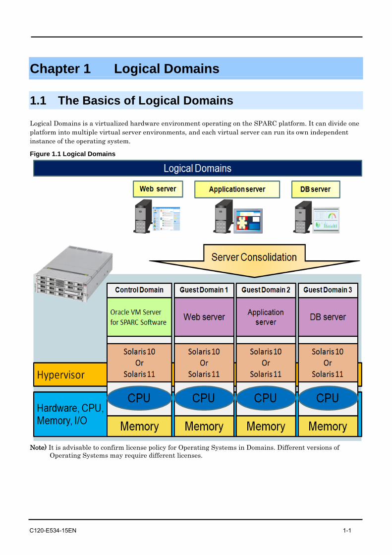
Logical Domains is a virtualized hardware environment operating on the SPARC platform. It can divide one platform into multiple virtual server environments, and each virtual server can run its own independent instance of the operating system.
Figure 1.1 Logical Domains
Note) It is advisable to confirm license policy for Operating Systems in Domains. Different versions of
Operating Systems may require different licenses.
Chapter 1 Logical Domains
1-2 C120-E534-15EN
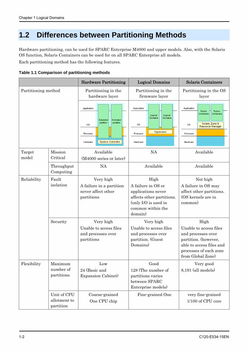
1.2 Differences between Partitioning Methods
Hardware partitioning, can be used for SPARC Enterprise M4000 and upper models. Also, with the Solaris OS function, Solaris Containers can be used for on all SPARC Enterprise all models. Each partitioning method has the following features.
Table 1.1 Comparison of partitioning methods
Hardware Partitioning Logical Domains Solaris Containers
Partitioning method Partitioning in the hardware layer
Partitioning in the firmware layer
Partitioning in the OS layer
Target model
Mission Critical
Available (M4000 series or later)
NA Available
Throughput Computing
NA Available Available
Reliability Fault isolation
Very high A failure in a partition never affect other partitions
High A failure in OS or applications never affects other partitions. (only I/O is used in common within the domain)
Not high A failure in OS may affect other partitions. (OS kernels are in common)
Security Very high Unable to access files and processes over partitions
Very high Unable to access files and processes over partition. (Guest Domains)
High Unable to access files and processes over partition. (however, able to access files and processes of each zone from Global Zone)
Flexibility Maximum number of partitions
Low 24 (Basic and Expansion Cabinet)
Good 128 (The number of partitions varies between SPARC Enterprise models)
Very good 8,191 (all models)
Unit of CPU allotment to partition
Coarse-grained One CPU chip
Fine-grained One very fine-grained 1/100 of CPU core
1.2 Differences between Partitioning Methods
C120-E534-15EN 1-3
Hardware Partitioning Logical Domains Solaris Containers
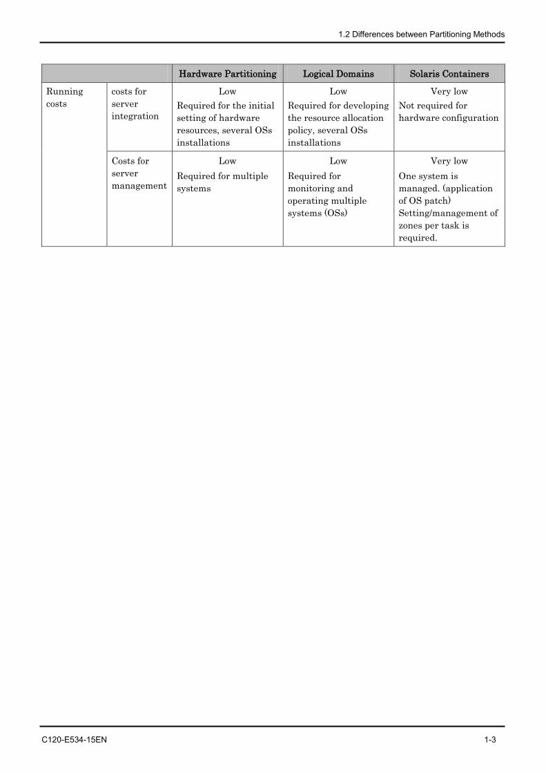
Running costs
costs for server integration
Low Required for the initial setting of hardware resources, several OSs installations
Low Required for developing the resource allocation policy, several OSs installations
Very low Not required for hardware configuration
Costs for server management
Low Required for multiple systems
Low Required for monitoring and operating multiple systems (OSs)
Very low One system is managed. (application of OS patch) Setting/management of zones per task is required.
Chapter 1 Logical Domains
1-4 C120-E534-15EN
1.3 The Basics of Hypervisor
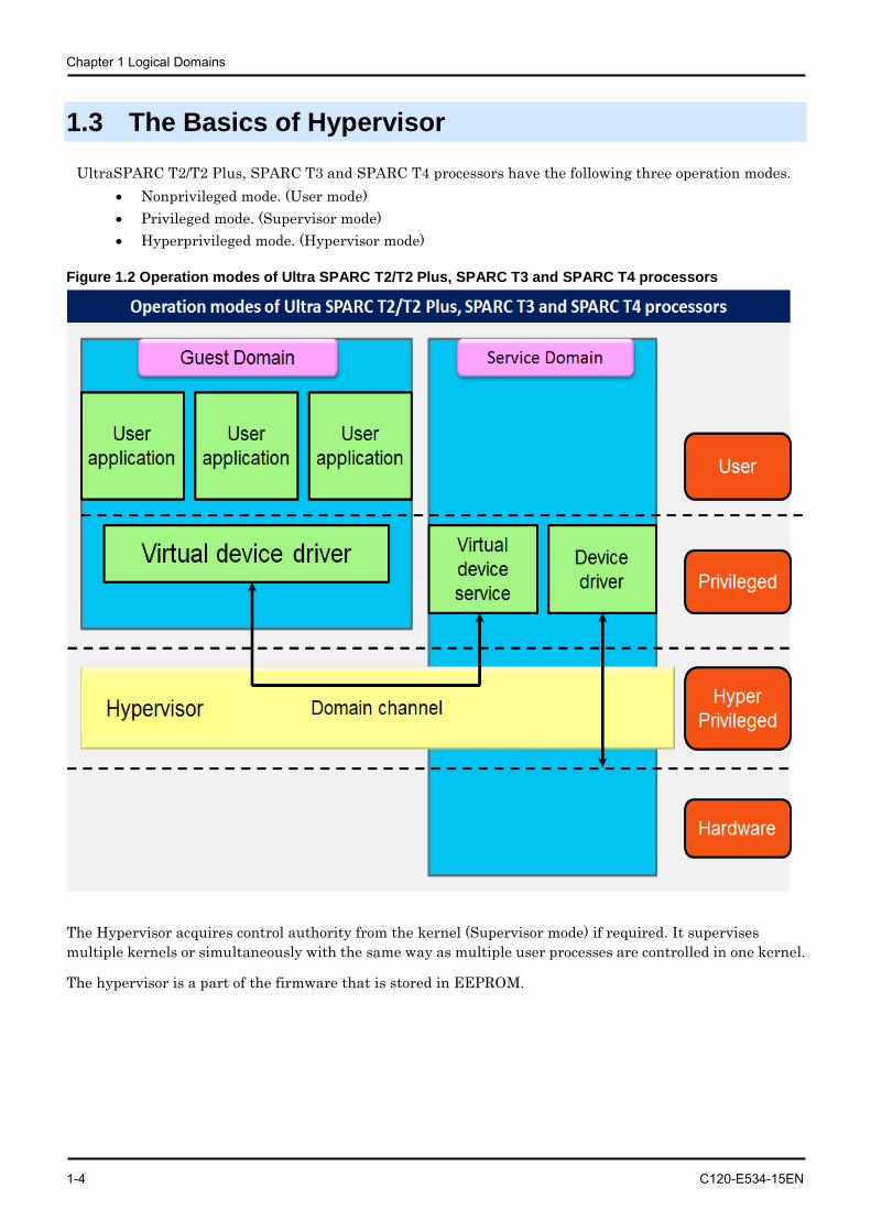
UltraSPARC T2/T2 Plus, SPARC T3 and SPARC T4 processors have the following three operation modes. • Nonprivileged mode. (User mode) • Privileged mode. (Supervisor mode) • Hyperprivileged mode. (Hypervisor mode)
Figure 1.2 Operation modes of Ultra SPARC T2/T2 Plus, SPARC T3 and SPARC T4 processors
The Hypervisor acquires control authority from the kernel (Supervisor mode) if required. It supervises multiple kernels or simultaneously with the same way as multiple user processes are controlled in one kernel.
The hypervisor is a part of the firmware that is stored in EEPROM.
1.4 Role of the Domain in Logical Domains
C120-E534-15EN 1-5
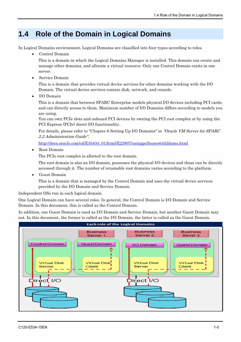
1.4 Role of the Domain in Logical Domains In Logical Domains environment, Logical Domains are classified into four types according to roles.
• Control Domain This is a domain in which the Logical Domains Manager is installed. This domain can create and manage other domains, and allocate a virtual resource. Only one Control Domain exists in one server.
• Service Domain This is a domain that provides virtual device services for other domains working with the I/O Domain. The virtual device services contain disk, network, and console.
• I/O Domain This is a domain that between SPARC Enterprise models physical I/O devices including PCI cards, and can directly access to them. Maximum number of I/O Domains differs according to models you are using. You can own PCIe slots and onboard PCI devices by owning the PCI root complex or by using the PCI Express (PCIe) direct I/O functionality. For details, please refer to "Chapter 6 Setting Up I/O Domains" in "Oracle VM Server for SPARC 2.2 Administration Guide". http://docs.oracle.com/cd/E35434_01/html/E23807/usingpcibuseswithldoms.html
• Root Domain The PCIe root complex is allotted to the root domain. The root domain is also an I/O domain, possesses the physical I/O devices and those can be directly accessed through it. The number of retainable root domains varies according to the platform.
• Guest Domain This is a domain that is managed by the Control Domain and uses the virtual device services provided by the I/O Domain and Service Domain.
Independent OSs run in each logical domain. One Logical Domain can have several roles. In general, the Control Domain is I/O Domain and Service Domain. In this document, this is called as the Control Domain. In addition, one Guest Domain is used as I/O Domain and Service Domain, but another Guest Domain may not. In this document, the former is called as the I/O Domain, the latter is called as the Guest Domain.
Chapter 1 Logical Domains
1-6 C120-E534-15EN
1.5 Resource Components • Virtual CPU
Virtual CPUs can be allotted in units of threads upto 128. The Virtual CPU can be transferred between domains without stopping them. The operations for addition/deletion can be operated on the Control Domain.
• Memory The unit of minimum physical memory segment that Solaris OS manages is 4MB. You can allocate memory by 4MB to each domain.
• Virtual Disks The virtual disk service (vds) controls physical disks to provide each domain with the virtual disks. You can use the following types of disk as entities of the virtual disks. However, there are some restrictions depending on the type of entities.
- Physical disks - Disk slices (Boot disk is not available for any releases older than Solaris10 10/08.) - UFS files - Loopback file system (Not available for boot disk.) - ZFS volumes/ZFS files (supported by Logical Domains 1.1 or later)
• Virtual Console You can access the virtual consoles of each domain using the console service of the Control Domain and telnet command.
• Virtual Network A Virtual Network device (vnet) can be defined for each domain. The Virtual Network device interact with other domains or physical networks via the virtual switch (vsw) of the Service Domains.
• Virtual Cipher Unit You can virtualize the cipher unit that UltraSPARC T2/T2 Plus processors or SPARC T3 processors has per 1 core, and allocate it to any domain. (This is not available as of publishment of this document.)
CAUTION
Some functions are not supported by Fujitsu. Refer to " Chapter 1 Oracle VM Server for SPARC 2.2 functions are not supported" in "SPARC Enterprise Oracle VM Server for SPARC Important Information".
http://www.fujitsu.com/global/services/computing/server/sparcenterprise/products/software/ldoms/
C120-E534-15EN 2-1
Chapter 2 Logical Domains Application
2.1 Policy on Selecting Partitions
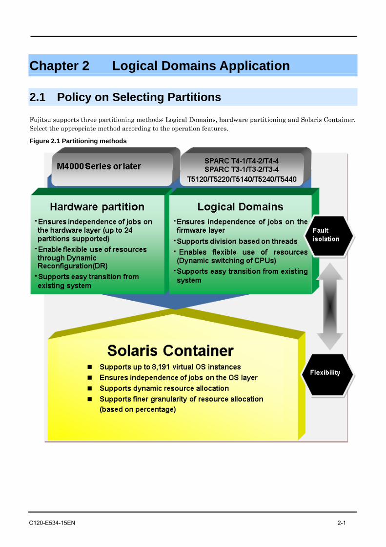
Fujitsu supports three partitioning methods: Logical Domains, hardware partitioning and Solaris Container. Select the appropriate method according to the operation features.
Figure 2.1 Partitioning methods
Chapter 2 Logical Domains Application
2-2 C120-E534-15EN
2.2 Application Purposes of Logical Domains
Logical Domains can be used for the following purposes:
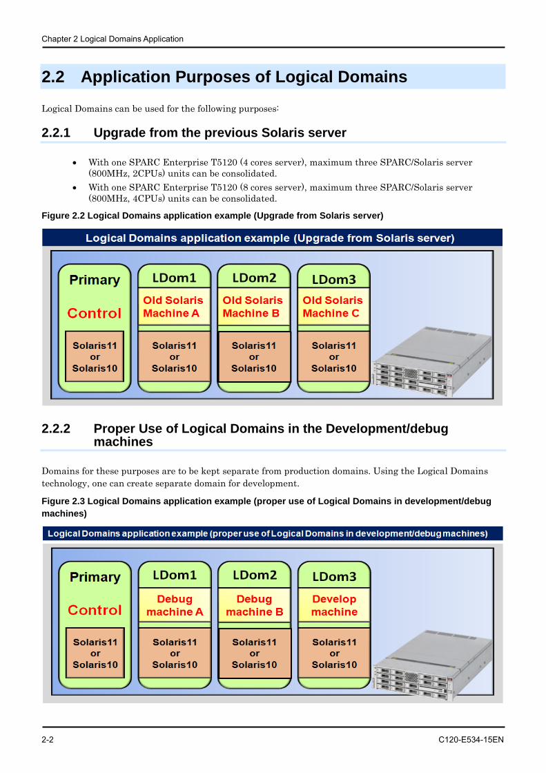
2.2.1 Upgrade from the previous Solaris server
• With one SPARC Enterprise T5120 (4 cores server), maximum three SPARC/Solaris server (800MHz, 2CPUs) units can be consolidated.
• With one SPARC Enterprise T5120 (8 cores server), maximum three SPARC/Solaris server (800MHz, 4CPUs) units can be consolidated.
Figure 2.2 Logical Domains application example (Upgrade from Solaris server)
2.2.2 Proper Use of Logical Domains in the Development/debug machines
Domains for these purposes are to be kept separate from production domains. Using the Logical Domains technology, one can create separate domain for development.
Figure 2.3 Logical Domains application example (proper use of Logical Domains in development/debug machines)
2.3 Operations for which Logical Domains can be used
C120-E534-15EN 2-3
2.3 Operations for which Logical Domains can be used
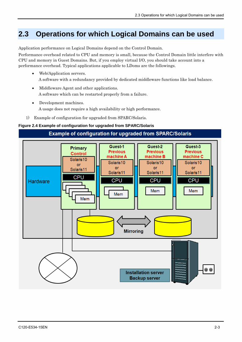
Application performance on Logical Domains depend on the Control Domain. Performance overhead related to CPU and memory is small, because the Control Domain little interfere with CPU and memory in Guest Domains. But, if you employ virtual I/O, you should take account into a performance overhead. Typical applications applicable to LDoms are the followings.
• Web/Application servers. A software with a redundancy provided by dedicated middleware functions like load balance.
• Middleware Agent and other applications. A software which can be restarted properly from a failure.
• Development machines. A usage does not require a high availability or high performance.
1) Example of configuration for upgraded from SPARC/Solaris.
Figure 2.4 Example of configuration for upgraded from SPARC/Solaris
Chapter 2 Logical Domains Application
2-4 C120-E534-15EN
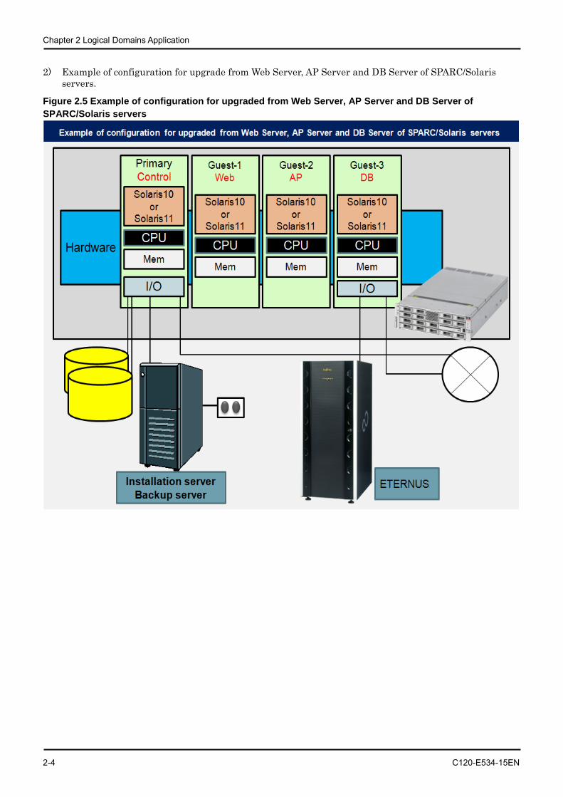
2) Example of configuration for upgrade from Web Server, AP Server and DB Server of SPARC/Solaris servers.
Figure 2.5 Example of configuration for upgraded from Web Server, AP Server and DB Server of SPARC/Solaris servers
2.3 Operations for which Logical Domains can be used
C120-E534-15EN 2-5
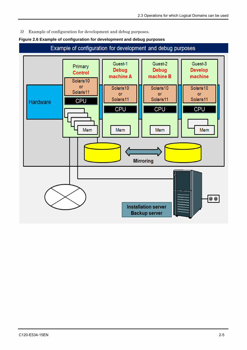
3) Example of configuration for development and debug purposes.
Figure 2.6 Example of configuration for development and debug purposes
Chapter 2 Logical Domains Application
2-6 C120-E534-15EN
2.4 Logical Domains Performance
• There are almost no overheads related to CPU/memory resource.
• Please allocate units of cores to the Control Domain/Guest Domain for the purpose of minimizing CPU overhead influence.
• The performance of the virtual I/O may be degraded compared to the performance of direct I/O, which handles I/O directly. This is because Control or I/O Domains intermediate such data transfer. In case that high I/O load is expected, I/O, Fujitsu recommends a preliminary performance test. Please contact the relevant sales in your regions if a device for advanced verification is required.
• The CPU load of the Control Domain and/or I/O Domain increases when the virtual network device (vnet) is used in the Guest Domain.
• Because accesses to one of network card is done on one CPU thread in the Control or I/O Domains, please use the same number of network cards as that of the number of vnets and allocate the same number of CPU threads to the Control Domain.
C120-E534-15EN 3-1
Chapter 3 Logical Domains Configuration Design
3.1 Notices for Logical Domains configuration
3.1.1 Configurations
• For Logical Domains Manager Software, an installation server is required to install to the Guest Domain.(Logical Domains1.0.2)
• Before installing Logical Domains, please create mirrors of internal disks. (with PRIMECLUSTER GDS or Solaris Volume Manager or ZFS)
• Please install Enhanced Support Facility (ESF) in the Control Domain, I/O Domain and Guest Domain.
• Allocate CPU in units of core to the Control Domain, I/O Domain and Guest Domains.
• Refer to [How to set up REMCS in Logical Domains], which is the ESF user's guide (REMCS version) when using REMCS (Remote Customer Support system).
• The following functions cannot be used in the domains where Solaris containers exist.
- Dynamic Reconfiguration of Virtual CPUs
- Migrating an Active Domain
3.1.2 Upgrading Firmware
The firmware must be upgraded when the firmware version is not supported. Also, in order to use the new functions, the firmware may need to be upgraded. About the Downloading the latest firmware, please contact to below.
• SPARC Enterprise contacts http://www.fujitsu.com/global/contact/computing/sparce_index.html
Chapter 3 Logical Domains Configuration Design
3-2 C120-E534-15EN
3.1.3 Middleware support
• For security reasons, DO NOT install the business application software in the Control Domain. • Despite the note above, the following middleware products can be installed in the Control Domain.
- Enhanced Support Facility It should be installed to each domain. For detail of the installation refer to the Enhanced Support Facility document.
- PRIMECLUSTER GDS GDS can use disks connected to Direct I/O or PCI(e) direct I/O. Please check "Software & Operating Systems (OS)". (only for Oracle Solaris 10) http://www.fujitsu.com/global/services/computing/server/primequest/products/software/
- PRIMECLUSTER GLS (Oracle Solaris 10 only) Only NIC switching mode is supported in LDoms environments. GLS can be used also in Guest Domains.
- Solaris Volume Manager (Solaris VM) Solaris Volume Manager can be used in disks connected by the Direct I/O or PCI(e) direct I/O. Only for Oracle Solaris 11, system disks are not available with Solaris VM. For Oracle Solaris 10, both system and data disks are available with Solaris VM.
- Server System Manager (SSM) Agent (Oracle Solaris 10 only) It is unable to install and use SSM agents on Guest Domains.(SSM is not available with Guest Domain) Power-off operation from SSM is disabled in the Logical Domains environment.
• On Guest Domains, middleware products works normally with Oracle Solaris10 and Oracle Solaris11. But managers of middleware products must be installed in the Control Domain for isolating them form a failure of a Guest Domain. Only agents can be installed in Guest Domains.
• Availability of following products in Guest Domains was verified. Tests for controlling and monitoring hardware components in Logical Domains were confirmed. Because of hardware is controlled /monitored directly.
Table 3.1 Supported Middleware Applications
Product Name Operations in Guest Domain
Remarks
Enhanced Support Facility Available Installation in all domains is required.
Systemwalker CMGR Available The domain configuration is available only in business servers.
Systemwalker OMGR Available
Systemwalker SQC Available
• For ISV (Independent Software Vendors)/IHV(Independent Hardware Vendors) products, please contact relevant vendors.
3.1 Notices for Logical Domains configuration
C120-E534-15EN 3-3
3.1.4 I/O Availability
• The Direct I/O of the I/O Domain is not available in SPARC T4-1/T3-1 and SPARC Enterprise T5120/T5220.
• The following I/Os are not available from Guest Domains. - Graphic card - Serial port - USB - DVD equipment (*1)
*1) Available from a domain acting as both I/O and Guest Domains. - Connect external via a network for backup and restore in Guest Domains.
3.1.5 Network
The NIC driver, which is allocated to the virtual switch (vsw), is compliant only with the GLDv3 (Generic LAN Driver version3). The driver compliant with the network is the FUJITSU PCI Gigabit Ethernet (fjgi: version 4 or later, fjxge) or e1000g, nxge, igb, ixgbe.
3.1.6 Maintenance
• For details of the procedures, please refer to "Chapter 8 Tasks Required to Replace Parts".

Chapter 3 Logical Domains Configuration Design
3-4 C120-E534-15EN
3.2 Logical Domains Configuration Overview In SPARC Enterprise T Series, Logical Domains configuration differs according to machine models. For more information, please see "Notes on SPARC Enterprise T Series" in "SPARC Enterprise Oracle VM Server for SPARC Important Information".
http://www.fujitsu.com/global/services/computing/server/sparcenterprise/products/software/ldoms/
3.3 Logical Domains Configuration units
The hardware resources including CPU and memory are allocated to Logical Domains as follows.
• CPU can be allocated to the Control Domain, I/O Domain and Guest Domain by core.
• The minimum memory requirement for Control Domain is 1GB, recommended memory size in Control Domain is 4GB, while the minimum memory size is 1GB.
• Memory For I/O domain, the Control Domain providing the virtual disk services to other Guest Domains, needs to be added according to the disk I/O load in other Guest Domain.
• When three or more application programs causing high disk I/O load run at one time, please allocate memory to the Control Domain or I/O domain by referring to the following standard.
The number of high disk I/O load programs running simultaneously 0 to 2 3 4 5 6 7
Memory of the Control Domain or I/O domain(GB) 4 5 6 7 8 9
• If the sar -g command continues to output non 0 as the value of 'pgscan/s' on the Control Domain providing the virtual disk services or I/O domain, memory insufficiency may occur. For more information, please refer to "Chapter 13 Monitoring System Performance (Tasks)” in "System Administration Guide: Advanced Administration".
http://download.oracle.com/docs/cd/E19253-01/817-0403/index.html
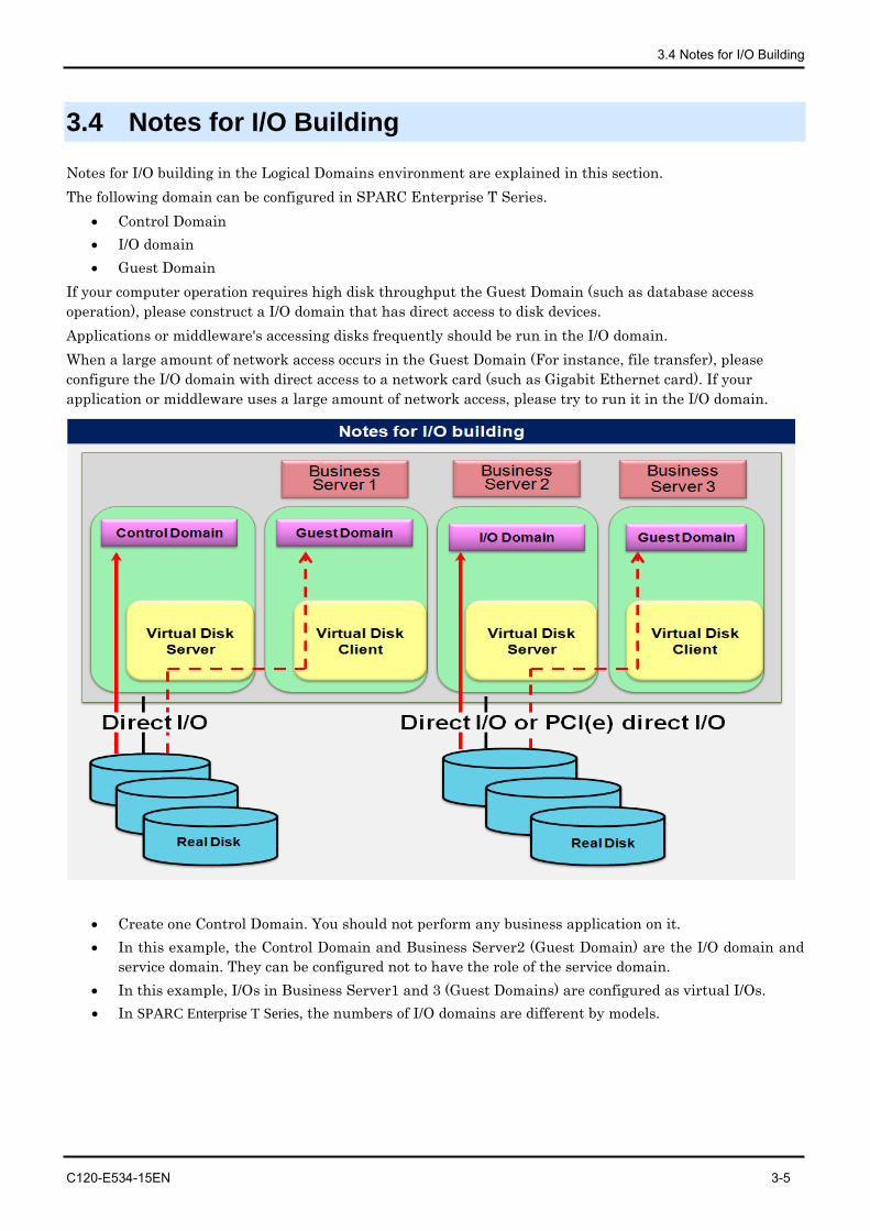
3.4 Notes for I/O Building
C120-E534-15EN 3-5
3.4 Notes for I/O Building
Notes for I/O building in the Logical Domains environment are explained in this section. The following domain can be configured in SPARC Enterprise T Series.
• Control Domain • I/O domain • Guest Domain
If your computer operation requires high disk throughput the Guest Domain (such as database access operation), please construct a I/O domain that has direct access to disk devices. Applications or middleware's accessing disks frequently should be run in the I/O domain. When a large amount of network access occurs in the Guest Domain (For instance, file transfer), please configure the I/O domain with direct access to a network card (such as Gigabit Ethernet card). If your application or middleware uses a large amount of network access, please try to run it in the I/O domain.
• Create one Control Domain. You should not perform any business application on it. • In this example, the Control Domain and Business Server2 (Guest Domain) are the I/O domain and
service domain. They can be configured not to have the role of the service domain. • In this example, I/Os in Business Server1 and 3 (Guest Domains) are configured as virtual I/Os. • In SPARC Enterprise T Series, the numbers of I/O domains are different by models.
Chapter 3 Logical Domains Configuration Design
3-6 C120-E534-15EN
3.4.1 Allocation of disk device • Please use Direct I/O to connect internal disks to the Control Domain. • Please use Direct I/O or PCI(e) direct I/O to connect external disks (file unit devices, disk array
devices) to the Control Domain or I/O domains. • Fujitsu recommends to use Direct I/O or PCI(e) direct I/O in I/O Domains for data and system disks.. • Please use Direct I/O to allocate NIC to the Control Domain. • To Guest Domains, use virtual disk and virtual network which allow to connect physical disks and
networks through the Control Domain or I/O Domains. Please notice Direct I/O or PCI(e) direct I/O is not available in Guest Domains.
• Virtual Disk can allocate the following the disk types. - Solaris VM volumes - Physical devices
Internal disks - File Unit connected with SCSI card - File Unit connected with SAS card - ETERNUS 2000/3000/4000/6000/8000 series connected with 8GFC card
- Use disk mirroring software such as PRIMECLUSTER GDS, Solaris Volume Manager, and ZFS to mirror internal disks and external file unit devices. Fujitsu recommends using other disks for Virtual Disks from disks in Control Domain or I/O Domains. If you use the same disk, please separate partitions. We recommend that different disks be allocated for each domain.
- Do not delete a virtual I/O device. For more information, please see "Chapter 7 Using Virtual Disks" in "Oracle VM Server for SPARC 2.2 Administration Guide", provided by Oracle Corporation. http://docs.oracle.com/cd/E35434_01/html/E23807/usingvirtualdiskswithldoms.html
3.4.2 Notes for RAID software
• RAID software can be installed on the Control Domain and I/O domains to which Direct I/O is connected. However, RAID functionality is not available in Guest Domains.
• Solaris volume manager (hereinafter referred to as Solaris VM) is also available in the Control Domain where Direct I/O is connected or I/O domain.
• The disk that implements mirroring in the Control Domain or I/O domain can be allocated to another domain as the virtual disk.
• For using the GDS operation management view of PRIMECLUSTER GDS, change the security settings of Solaris Security Toolkit (SST) in order to access the system from the web browser of the client PC.
3.4.3 Notes on the connection of the disk array device (ETERNUS, Sun STK)
• Devices with multi-path configuration can be used with the ETMPD (ETERNUS multi-path driver), and MPxIO in the Control Domain or I/O domain. Moreover, these disks can be allocated to the virtual disk. Note) ETERNUS multipath driver (ETMPD) is not supported by Oracle Solaris 11.
Fujitsu recommends using MPxIO with Oracle Solaris 11.
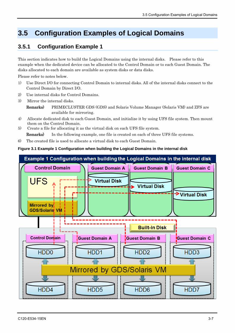
3.5 Configuration Examples of Logical Domains
C120-E534-15EN 3-7
3.5 Configuration Examples of Logical Domains
3.5.1 Configuration Example 1
This section indicates how to build the Logical Domains using the internal disks. Please refer to this example when the dedicated device can be allocated to the Control Domain or to each Guest Domain. The disks allocated to each domain are available as system disks or data disks. Please refer to notes below. 1) Use Direct I/O for connecting Control Domain to internal disks. All of the internal disks connect to the
Control Domain by Direct I/O. 2) Use internal disks for Control Domains. 3) Mirror the internal disks.
Remarks) PRIMECLUSTER GDS (GDS) and Solaris Volume Manager (Solaris VM) and ZFS are available for mirroring.
4) Allocate dedicated disk to each Guest Domain, and initialize it by using UFS file system. Then mount them on the Control Domain.
5) Create a file for allocating it as the virtual disk on each UFS file system. Remarks) In the following example, one file is created on each of three UFS file systems.
6) The created file is used to allocate a virtual disk to each Guest Domain.
Figure 3.1 Example 1 Configuration when building the Logical Domains in the internal disk
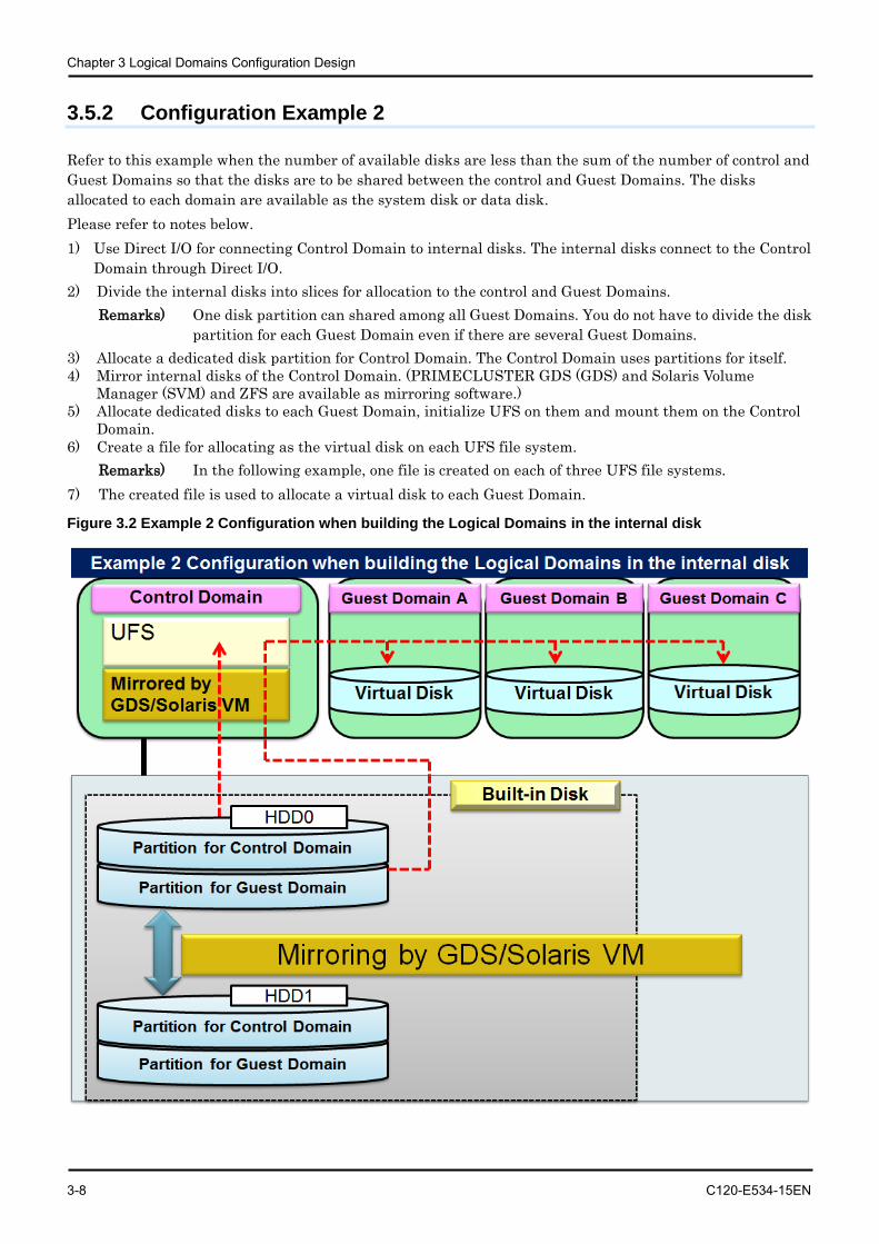
Chapter 3 Logical Domains Configuration Design
3-8 C120-E534-15EN
3.5.2 Configuration Example 2
Refer to this example when the number of available disks are less than the sum of the number of control and Guest Domains so that the disks are to be shared between the control and Guest Domains. The disks allocated to each domain are available as the system disk or data disk. Please refer to notes below. 1) Use Direct I/O for connecting Control Domain to internal disks. The internal disks connect to the Control
Domain through Direct I/O. 2) Divide the internal disks into slices for allocation to the control and Guest Domains.
Remarks) One disk partition can shared among all Guest Domains. You do not have to divide the disk partition for each Guest Domain even if there are several Guest Domains.
3) Allocate a dedicated disk partition for Control Domain. The Control Domain uses partitions for itself. 4) Mirror internal disks of the Control Domain. (PRIMECLUSTER GDS (GDS) and Solaris Volume
Manager (SVM) and ZFS are available as mirroring software.) 5) Allocate dedicated disks to each Guest Domain, initialize UFS on them and mount them on the Control
Domain. 6) Create a file for allocating as the virtual disk on each UFS file system.
Remarks) In the following example, one file is created on each of three UFS file systems. 7) The created file is used to allocate a virtual disk to each Guest Domain.
Figure 3.2 Example 2 Configuration when building the Logical Domains in the internal disk
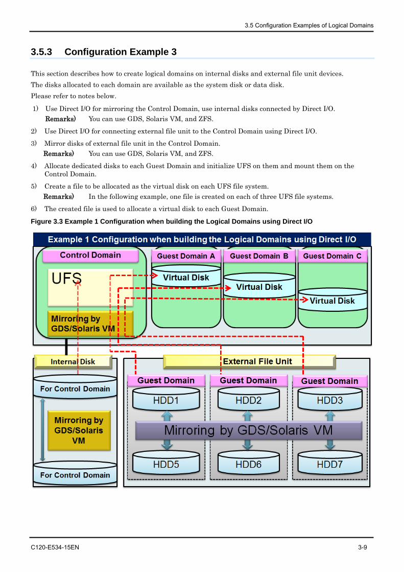
3.5 Configuration Examples of Logical Domains
C120-E534-15EN 3-9
3.5.3 Configuration Example 3
This section describes how to create logical domains on internal disks and external file unit devices. The disks allocated to each domain are available as the system disk or data disk. Please refer to notes below.
1) Use Direct I/O for mirroring the Control Domain, use internal disks connected by Direct I/O. Remarks) You can use GDS, Solaris VM, and ZFS.
2) Use Direct I/O for connecting external file unit to the Control Domain using Direct I/O.
3) Mirror disks of external file unit in the Control Domain. Remarks) You can use GDS, Solaris VM, and ZFS.
4) Allocate dedicated disks to each Guest Domain and initialize UFS on them and mount them on the Control Domain.
5) Create a file to be allocated as the virtual disk on each UFS file system. Remarks) In the following example, one file is created on each of three UFS file systems.
6) The created file is used to allocate a virtual disk to each Guest Domain.
Figure 3.3 Example 1 Configuration when building the Logical Domains using Direct I/O
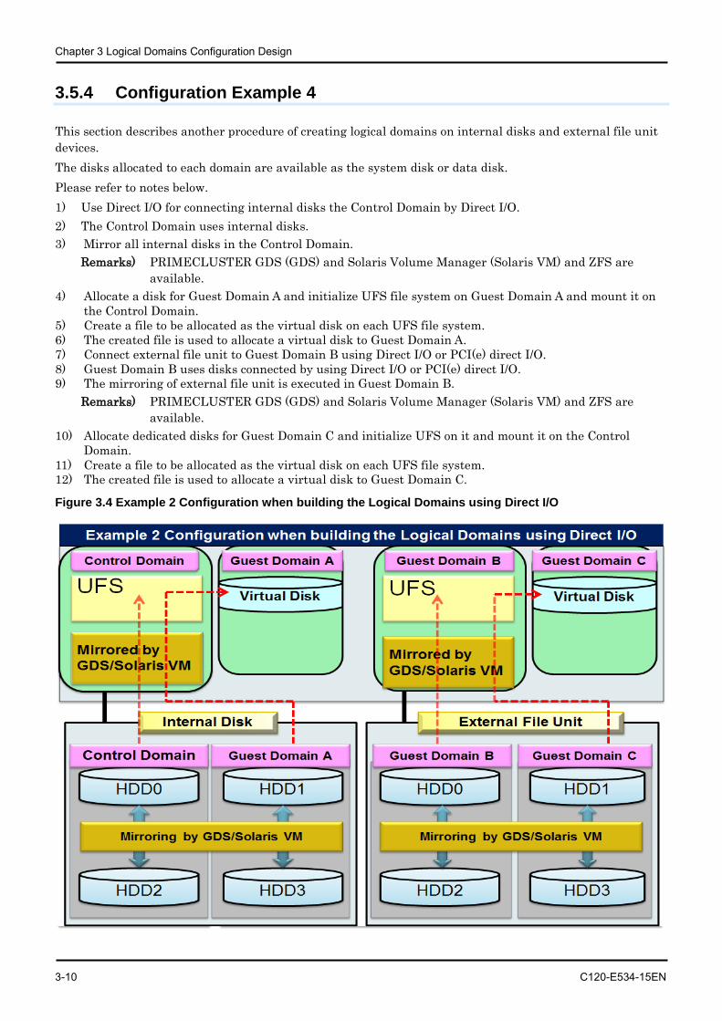
Chapter 3 Logical Domains Configuration Design
3-10 C120-E534-15EN
3.5.4 Configuration Example 4
This section describes another procedure of creating logical domains on internal disks and external file unit devices. The disks allocated to each domain are available as the system disk or data disk. Please refer to notes below. 1) Use Direct I/O for connecting internal disks the Control Domain by Direct I/O. 2) The Control Domain uses internal disks. 3) Mirror all internal disks in the Control Domain.
Remarks) PRIMECLUSTER GDS (GDS) and Solaris Volume Manager (Solaris VM) and ZFS are available.
4) Allocate a disk for Guest Domain A and initialize UFS file system on Guest Domain A and mount it on the Control Domain.
5) Create a file to be allocated as the virtual disk on each UFS file system. 6) The created file is used to allocate a virtual disk to Guest Domain A. 7) Connect external file unit to Guest Domain B using Direct I/O or PCI(e) direct I/O. 8) Guest Domain B uses disks connected by using Direct I/O or PCI(e) direct I/O. 9) The mirroring of external file unit is executed in Guest Domain B.
Remarks) PRIMECLUSTER GDS (GDS) and Solaris Volume Manager (Solaris VM) and ZFS are available.
10) Allocate dedicated disks for Guest Domain C and initialize UFS on it and mount it on the Control Domain.
11) Create a file to be allocated as the virtual disk on each UFS file system. 12) The created file is used to allocate a virtual disk to Guest Domain C.
Figure 3.4 Example 2 Configuration when building the Logical Domains using Direct I/O
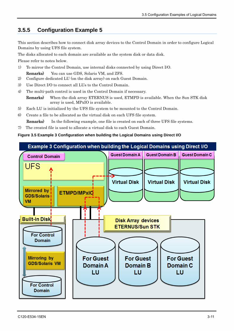
3.5 Configuration Examples of Logical Domains
C120-E534-15EN 3-11
3.5.5 Configuration Example 5
This section describes how to connect disk array devices to the Control Domain in order to configure Logical Domains by using UFS file system. The disks allocated to each domain are available as the system disk or data disk. Please refer to notes below. 1) To mirror the Control Domain, use internal disks connected by using Direct I/O.
Remarks) You can use GDS, Solaris VM, and ZFS. 2) Configure dedicated LU (on the disk array) on each Guest Domain. 3) Use Direct I/O to connect all LUs to the Control Domain. 4) The multi-path control is used in the Control Domain if necessary.
Remarks) When the disk array ETERNUS is used, ETMPD is available. When the Sun STK disk array is used, MPxIO is available.
5) Each LU is initialized by the UFS file system to be mounted to the Control Domain. 6) Create a file to be allocated as the virtual disk on each UFS file system.
Remarks) In the following example, one file is created on each of three UFS file systems. 7) The created file is used to allocate a virtual disk to each Guest Domain.
Figure 3.5 Example 3 Configuration when building the Logical Domains using Direct I/O
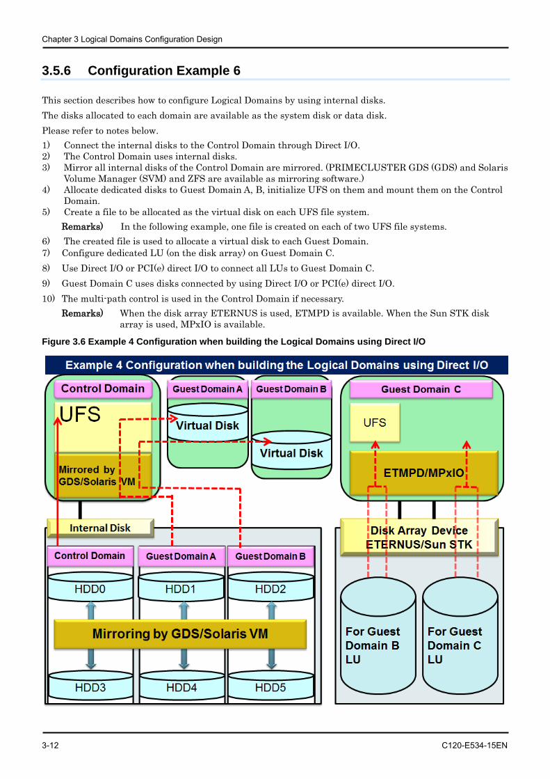
Chapter 3 Logical Domains Configuration Design
3-12 C120-E534-15EN
3.5.6 Configuration Example 6
This section describes how to configure Logical Domains by using internal disks. The disks allocated to each domain are available as the system disk or data disk. Please refer to notes below. 1) Connect the internal disks to the Control Domain through Direct I/O. 2) The Control Domain uses internal disks. 3) Mirror all internal disks of the Control Domain are mirrored. (PRIMECLUSTER GDS (GDS) and Solaris
Volume Manager (SVM) and ZFS are available as mirroring software.) 4) Allocate dedicated disks to Guest Domain A, B, initialize UFS on them and mount them on the Control
Domain. 5) Create a file to be allocated as the virtual disk on each UFS file system.
Remarks) In the following example, one file is created on each of two UFS file systems. 6) The created file is used to allocate a virtual disk to each Guest Domain. 7) Configure dedicated LU (on the disk array) on Guest Domain C. 8) Use Direct I/O or PCI(e) direct I/O to connect all LUs to Guest Domain C. 9) Guest Domain C uses disks connected by using Direct I/O or PCI(e) direct I/O. 10) The multi-path control is used in the Control Domain if necessary.
Remarks) When the disk array ETERNUS is used, ETMPD is available. When the Sun STK disk array is used, MPxIO is available.
Figure 3.6 Example 4 Configuration when building the Logical Domains using Direct I/O
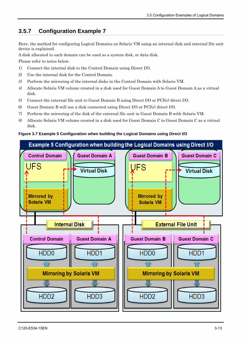
3.5 Configuration Examples of Logical Domains
C120-E534-15EN 3-13
3.5.7 Configuration Example 7
Here, the method for configuring Logical Domains on Solaris VM using an internal disk and external file unit device is explained. A disk allocated to each domain can be used as a system disk, or data disk. Please refer to notes below. 1) Connect the internal disk to the Control Domain using Direct I/O. 2) Use the internal disk for the Control Domain. 3) Perform the mirroring of the internal disks in the Control Domain with Solaris VM. 4) Allocate Solaris VM volume created in a disk used for Guest Domain A to Guest Domain A as a virtual
disk. 5) Connect the external file unit to Guest Domain B using Direct I/O or PCI(e) direct I/O. 6) Guest Domain B will use a disk connected using Direct I/O or PCI(e) direct I/O. 7) Perform the mirroring of the disk of the external file unit in Guest Domain B with Solaris VM. 8) Allocate Solaris VM volume created in a disk used for Guest Domain C to Guest Domain C as a virtual
disk.
Figure 3.7 Example 5 Configuration when building the Logical Domains using Direct I/O
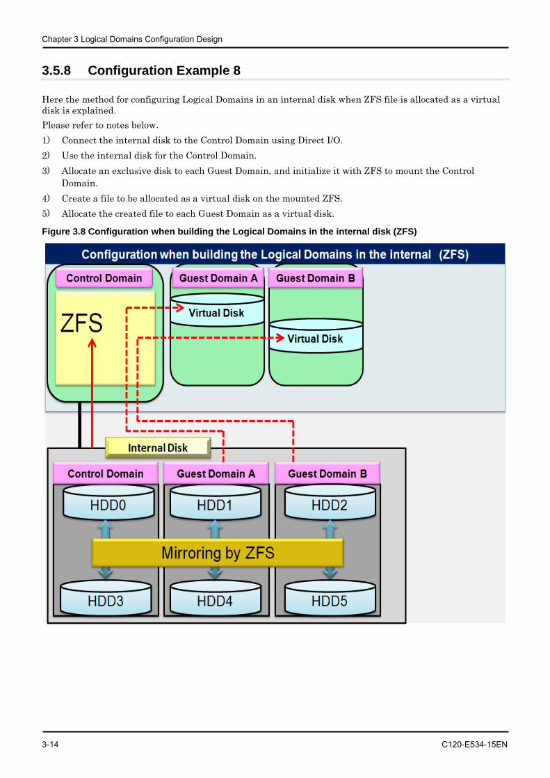
Chapter 3 Logical Domains Configuration Design
3-14 C120-E534-15EN
3.5.8 Configuration Example 8
Here the method for configuring Logical Domains in an internal disk when ZFS file is allocated as a virtual disk is explained. Please refer to notes below. 1) Connect the internal disk to the Control Domain using Direct I/O. 2) Use the internal disk for the Control Domain. 3) Allocate an exclusive disk to each Guest Domain, and initialize it with ZFS to mount the Control
Domain. 4) Create a file to be allocated as a virtual disk on the mounted ZFS. 5) Allocate the created file to each Guest Domain as a virtual disk.
Figure 3.8 Configuration when building the Logical Domains in the internal disk (ZFS)
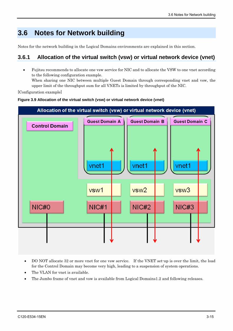
3.6 Notes for Network building
C120-E534-15EN 3-15
3.6 Notes for Network building
Notes for the network building in the Logical Domains environments are explained in this section.
3.6.1 Allocation of the virtual switch (vsw) or virtual network device (vnet)
• Fujitsu recommends to allocate one vsw service for NIC and to allocate the VSW to one vnet according to the following configuration example. When sharing one NIC between multiple Guest Domain through corresponding vnet and vsw, the upper limit of the throughput sum for all VNETs is limited by throughput of the NIC.
[Configuration example]
Figure 3.9 Allocation of the virtual switch (vsw) or virtual network device (vnet)
• DO NOT allocate 32 or more vnet for one vsw service. If the VNET set-up is over the limit, the load for the Control Domain may become very high, leading to a suspension of system operations.
• The VLAN for vnet is available. • The Jumbo frame of vnet and vsw is available from Logical Domains1.2 and following releases.
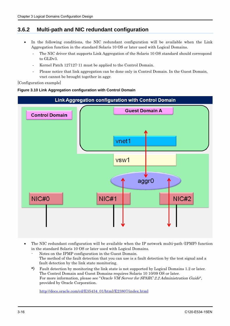
Chapter 3 Logical Domains Configuration Design
3-16 C120-E534-15EN
3.6.2 Multi-path and NIC redundant configuration
• In the following conditions, the NIC redundant configuration will be available when the Link Aggregation function in the standard Solaris 10 OS or later used with Logical Domains. - The NIC driver that supports Link Aggregation of the Solaris 10 OS standard should correspond
to GLDv3. - Kernel Patch 127127-11 must be applied to the Control Domain. - Please notice that link aggregation can be done only in Control Domain. In the Guest Domain,
vnet cannot be brought together in aggr. [Configuration example]
Figure 3.10 Link Aggregation configuration with Control Domain
• The NIC redundant configuration will be available when the IP network multi-path (IPMP) function
in the standard Solaris 10 OS or later used with Logical Domains. - Notes on the IPMP configuration in the Guest Domain.
The method of the fault detection that you can use is a fault detection by the test signal and a fault detection by the link state monitoring.
*) Fault detection by monitoring the link state is not supported by Logical Domains 1.2 or later. The Control Domain and Guest Domains requires Solaris 10 10/09 OS or later. For more information, please see "Oracle VM Server for SPARC 2.2 Administration Guide", provided by Oracle Corporation.
http://docs.oracle.com/cd/E35434_01/html/E23807/index.html
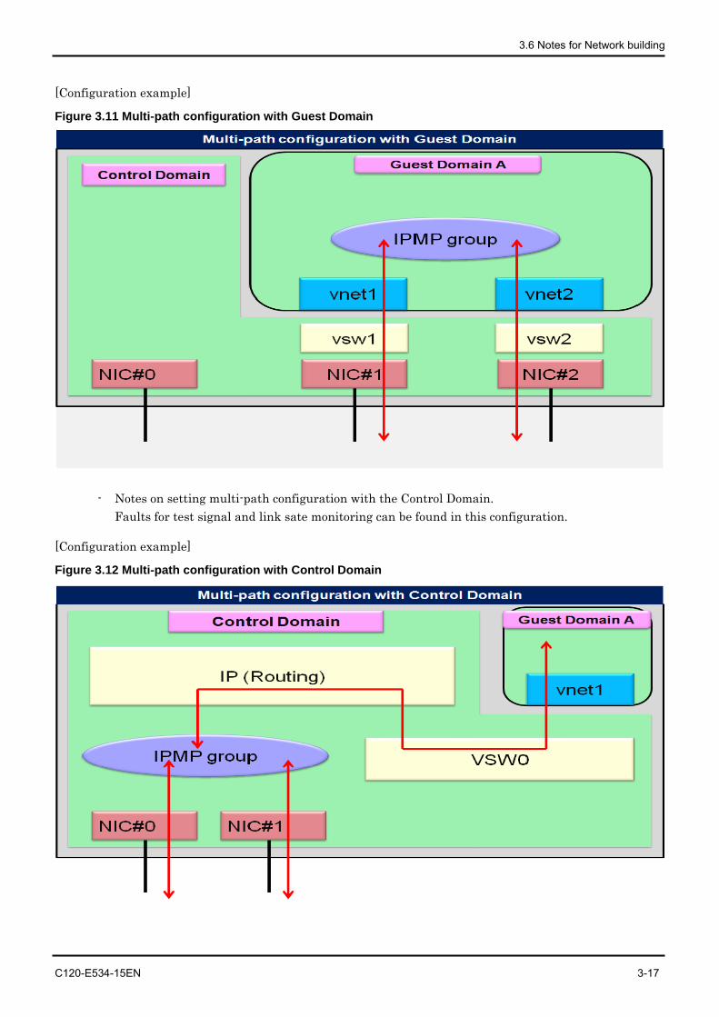
3.6 Notes for Network building
C120-E534-15EN 3-17
[Configuration example]
Figure 3.11 Multi-path configuration with Guest Domain
- Notes on setting multi-path configuration with the Control Domain. Faults for test signal and link sate monitoring can be found in this configuration.
[Configuration example]
Figure 3.12 Multi-path configuration with Control Domain

Chapter 3 Logical Domains Configuration Design
3-18 C120-E534-15EN
3.6.3 Notes for LAN in SPARC Enterprise T5140/T5240/T5440
When 10GbitEthernet XAUI card is installed, ports cannot be used because of exclusive use. For more information, please see "Notes on SPARC Enterprise T Series" in "SPARC Enterprise Oracle VM Server for SPARC Important Information".
http://www.fujitsu.com/global/services/computing/server/sparcenterprise/products/software/ldoms/
C120-E534-15EN 4-1
Chapter 4 Building Procedure (Example 1) This chapter describes how to configure the Control Domain and Guest Domain.
4.1 Precautions to Take Before Starting to Build
4.1.1 Logical Domains environment
As for system requirements for LDoms, please see "Notes on SPARC Enterprise T Series" in "SPARC Enterprise Oracle VM Server for SPARC Important Information".
http://www.fujitsu.com/global/services/computing/server/sparcenterprise/products/software/ldoms/
4.1.2 Firmware
For confirming firmware version numbers, you must visit different methods for ALOM and ILOM.
[ALOM] • Your firmware in System Controller (SC) can be confirmed.
sc> showhost Sun System Firmware 7.4.2 2011/11/19 09:17 Host flash versions: Hypervisor 1.10.4 2011/11/17 15:02 OpenBoot 4.33.4 2011/11/17 13:47 POST 4.33.4 2011/11/17 14:21
Remarks) The screenshots in Section 4.1 show examples of CLI operations of the system controller in the ALOM CMT shell as well as the execution results. Refer to "Integrated Lights Out Manager Additional Manual" on ALOM CMT shell.
[ILOM]
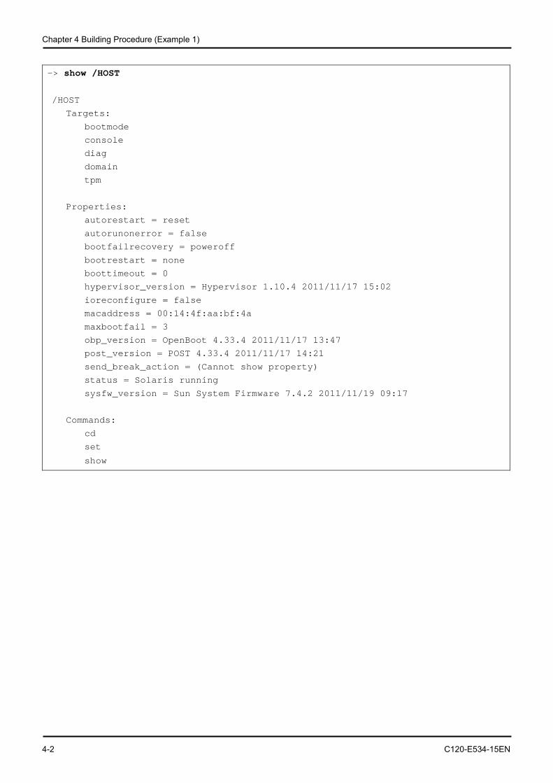
Chapter 4 Building Procedure (Example 1)
4-2 C120-E534-15EN
-> show /HOST
/HOST
Targets:
bootmode
console
diag
domain
tpm
Properties:
autorestart = reset
autorunonerror = false
bootfailrecovery = poweroff
bootrestart = none
boottimeout = 0
hypervisor_version = Hypervisor 1.10.4 2011/11/17 15:02
ioreconfigure = false
macaddress = 00:14:4f:aa:bf:4a
maxbootfail = 3
obp_version = OpenBoot 4.33.4 2011/11/17 13:47
post_version = POST 4.33.4 2011/11/17 14:21
send_break_action = (Cannot show property)
status = Solaris running
sysfw_version = Sun System Firmware 7.4.2 2011/11/19 09:17
Commands:
cd
set
show
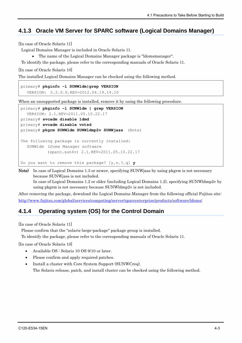
4.1 Precautions to Take Before Starting to Build
C120-E534-15EN 4-3
4.1.3 Oracle VM Server for SPARC software (Logical Domains Manager)
[In case of Oracle Solaris 11] Logical Domains Manager is included in Oracle Solaris 11.
• The name of the Logical Domains Manager package is "ldomsmanager". To identify the package, please refer to the corresponding manuals of Oracle Solaris 11.
[In case of Oracle Solaris 10] The installed Logical Domains Manager can be checked using the following method.
primary# pkginfo -l SUNWldm|grep VERSION VERSION: 2.2.0.0,REV=2012.04.19.14.10
When an unsupported package is installed, remove it by using the following procedure. primary# pkginfo -l SUNWldm | grep VERSION VERSION: 2.1,REV=2011.05.10.22.17 primary# svcadm disable ldmd primary# svcadm disable vntsd primary# pkgrm SUNWldm SUNWldmp2v SUNWjass (Note) The following package is currently installed: SUNWldm LDoms Manager software (sparc.sun4v) 2.1,REV=2011.05.10.22.17 Do you want to remove this package? [y,n,?,q] y
Note) In case of Logical Domains 1.3 or newer, specifying SUNWjass by using pkgrm is not necessary because SUNWjass is not included. In case of Logical Domains 1.2 or older (including Logical Domains 1.2), specifying SUNWldmp2v by using pkgrm is not necessary because SUNWldmp2v is not included.
After removing the package, download the Logical Domains Manager from the following official Fujitsu site: http://www.fujitsu.com/global/services/computing/server/sparcenterprise/products/software/ldoms/
4.1.4 Operating system (OS) for the Control Domain
[In case of Oracle Solaris 11] Please confirm that the "solaris-large-package" package group is installed. To identify the package, please refer to the corresponding manuals of Oracle Solaris 11.
[In case of Oracle Solaris 10] • Available OS : Solaris 10 OS 9/10 or later. • Please confirm and apply required patches. • Install a cluster with Core System Support (SUNWCreq).
The Solaris release, patch, and install cluster can be checked using the following method.
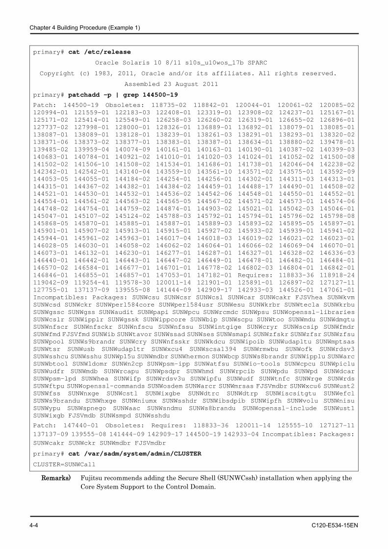
Chapter 4 Building Procedure (Example 1)
4-4 C120-E534-15EN
primary# cat /etc/release
Oracle Solaris 10 8/11 s10s_u10wos_17b SPARC
Copyright (c) 1983, 2011, Oracle and/or its affiliates. All rights reserved.
Assembled 23 August 2011
primary# patchadd -p | grep 144500-19
Patch: 144500-19 Obsoletes: 118735-02 118842-01 120044-01 120061-02 120085-02 120994-01 121559-01 122183-03 122408-01 123319-01 123908-02 124237-01 125167-01 125171-02 125414-01 125549-01 126258-03 126260-02 126319-01 126655-02 126896-01 127737-02 127998-01 128000-01 128326-01 136889-01 136892-01 138079-01 138085-01 138087-01 138089-01 138128-01 138239-01 138261-03 138291-01 138293-01 138320-02 138371-06 138373-02 138377-01 138383-01 138387-01 138634-01 138880-02 139478-01 139485-02 139959-04 140074-09 140161-01 140163-01 140190-01 140387-02 140399-03 140683-01 140784-01 140921-02 141010-01 141020-03 141024-01 141052-02 141500-08 141502-02 141506-10 141508-02 141534-01 141686-01 141738-01 142046-04 142238-02 142342-01 142542-01 143140-04 143559-10 143561-10 143571-02 143575-01 143592-09 144053-05 144055-01 144184-02 144254-01 144256-01 144302-01 144311-03 144313-01 144315-01 144367-02 144382-01 144384-02 144459-01 144488-17 144490-01 144508-02 144521-01 144530-01 144532-01 144536-02 144542-06 144548-01 144550-01 144552-01 144554-01 144561-02 144563-02 144565-05 144567-02 144571-02 144573-01 144574-06 144748-02 144754-01 144759-02 144874-01 144903-02 145021-01 145042-03 145046-01 145047-01 145107-02 145124-02 145788-03 145792-01 145794-01 145796-02 145798-08 145868-05 145870-01 145885-01 145887-01 145889-03 145893-02 145895-05 145897-01 145901-01 145907-02 145913-01 145915-01 145927-02 145933-02 145939-01 145941-02 145944-01 145961-02 145963-01 146017-04 146018-03 146019-02 146021-02 146023-01 146028-05 146030-01 146058-02 146062-02 146064-01 146066-02 146069-04 146070-01 146073-01 146132-01 146230-01 146277-01 146287-01 146327-01 146328-02 146336-03 146440-01 146442-01 146443-01 146447-02 146449-01 146478-01 146482-01 146484-01 146570-02 146584-01 146677-01 146701-01 146778-02 146802-03 146804-01 146842-01 146846-01 146855-01 146857-01 147053-01 147182-01 Requires: 118833-36 118918-24 119042-09 119254-41 119578-30 120011-14 121901-01 125891-01 126897-02 127127-11 127755-01 137137-09 139555-08 141444-09 142909-17 142933-03 144526-01 147061-01 Incompatibles: Packages: SUNWcsu SUNWcsr SUNWcsl SUNWcar SUNWcakr FJSVhea SUNWkvm SUNWcsd SUNWckr SUNWperl584core SUNWperl584usr SUNWesu SUNWkrbr SUNWtecla SUNWkrbu SUNWgssc SUNWgss SUNWaudit SUNWpapi SUNWpcu SUNWrcmdc SUNWpsu SUNWopenssl-libraries SUNWcslr SUNWipplr SUNWgssk SUNWippcore SUNWbip SUNWscpu SUNWtoo SUNWmdu SUNWdmgtu SUNWnfscr SUNWnfsckr SUNWnfscu SUNWnfssu SUNWintgige SUNWcryr SUNWscsip SUNWfmdr SUNWfmd FJSVfmd SUNWib SUNWtavor SUNWssad SUNWses SUNWsmapi SUNWzfskr SUNWzfsr SUNWzfsu SUNWpool SUNWs9brandr SUNWcry SUNWnfsskr SUNWkdcu SUNWipoib SUNWudapltu SUNWmptsas SUNWtsr SUNWusb SUNWudapltr SUNWxcu4 SUNWscsa1394 SUNWrmwbu SUNWofk SUNWrdsv3 SUNWsshcu SUNWsshu SUNWpl5u SUNWmdbr SUNWhermon SUNWbcp SUNWs8brandr SUNWipplu SUNWarc SUNWbtool SUNWldomr SUNWn2cp SUNWpsm-ipp SUNWatfsu SUNWio-tools SUNWcpcu SUNWpiclu SUNWudfr SUNWmdb SUNWrcapu SUNWpsdpr SUNWhmd SUNWrpcib SUNWpdu SUNWpd SUNWdcar SUNWpsm-lpd SUNWhea SUNWifp SUNWrdsv3u SUNWipfu SUNWudf SUNWtnfc SUNWrge SUNWrds SUNWftpu SUNWopenssl-commands SUNWosdem SUNWarcr SUNWmrsas FJSVmdbr SUNWxcu6 SUNWust2 SUNWfss SUNWnxge SUNWcstl SUNWixgbe SUNWdtrc SUNWdtrp SUNWiscsitgtu SUNWefcl SUNWs9brandu SUNWhxge SUNWniumx SUNWsshdr SUNWibsdpib SUNWipfh SUNWvolu SUNWnisu SUNWypu SUNWspnego SUNWaac SUNWsndmu SUNWs8brandu SUNWopenssl-include SUNWust1 SUNWixgb FJSVmdb SUNWsmpd SUNWsshdu
Patch: 147440-01 Obsoletes: Requires: 118833-36 120011-14 125555-10 127127-11 137137-09 139555-08 141444-09 142909-17 144500-19 142933-04 Incompatibles: Packages: SUNWcakr SUNWckr SUNWmdbr FJSVmdbr
primary# cat /var/sadm/system/admin/CLUSTER
CLUSTER=SUNWCall
Remarks) Fujitsu recommends adding the Secure Shell (SUNWCssh) installation when applying the Core System Support to the Control Domain.
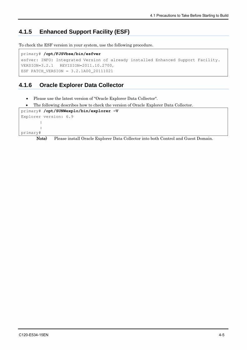
4.1 Precautions to Take Before Starting to Build
C120-E534-15EN 4-5
4.1.5 Enhanced Support Facility (ESF)
To check the ESF version in your system, use the following procedure.
primary# /opt/FJSVbse/bin/esfver esfver: INFO: Integrated Version of already installed Enhanced Support Facility. VERSION=3.2.1 REVISION=2011.10.2700, ESF PATCH_VERSION = 3.2.1A00_20111021
4.1.6 Oracle Explorer Data Collector
• Please use the latest version of "Oracle Explorer Data Collector". • The following describes how to check the version of Oracle Explorer Data Collector.
primary# /opt/SUNWexplo/bin/explorer -V Explorer version: 6.9
: :
primary# Note) Please install Oracle Explorer Data Collector into both Control and Guest Domain.
Chapter 4 Building Procedure (Example 1)
4-6 C120-E534-15EN
4.2 Building Flow
This section describes the steps for building Logical Domains system. 1) Determine the Logical Domains configuration. 2) Prepare the Logical Domains configuration scripts. 3) Define the Guest Domain Administrative Users. 4) Prepare the Files for the Virtual Disks. 5) Build the Control Domain. 6) Build the Guest Domain. 7) Retain the Logical Domains Configuration Information. 8) Install the Guest Domain. 9) Configuration of domain dependency relationships. This section explains 1) Determin the Logical Domains Configuration and 2) Prepare the Logical Domains configuration scripts.
4.2.1 Determining the Logical Domains configuration
This section describes configurations for the domains, the virtual services and the hardware resources allocated to each domain.
4.2.1.1 Logical Domains configuration name
The system controller can store up to eight Logical Domains configuration (config). The stored configurations can be switched by powering on or resetting the system after designating the configuration for future use. The configuration is specified as 'initial' in this document.
4.2.1.2 Domain names
Fujitsu recommends that the number of the domain operated in Logical Domains be less than or equal to the number of CPU cores. In this document, we take the case of SPARC Enterprise T5120/5220 and the domain structure is configured with the primary domain, ldom1, ldom2, and ldom3.
4.2.1.3 The virtual CPU allocation
The number of virtual CPU is expressed in units of threads or cores. It is recommended that you should set a multiple of the number of threads per CPU core for the number of virtual CPUs. When creating the Control Domain, set the number of virtual CPUs after changing it to the delayed reconfiguration mode. Change the Control Domain to the delayed reconfiguration mode by using the following command. # ldm start-reconf primary
After creating the Control Domain, the number of virtual CPUs of the Control Domain can be changed dynamically. For the details, please refer to each related manual of Oracle listed in "Reference Manuals" in "Preface" of this document.
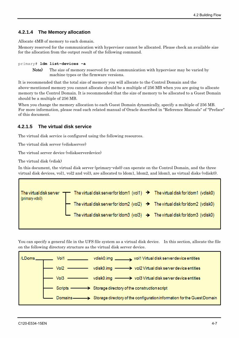
4.2 Building Flow
C120-E534-15EN 4-7
4.2.1.4 The Memory allocation
Allocate 4MB of memory to each domain. Memory reserved for the communication with hypervisor cannot be allocated. Please check an available size for the allocation from the output result of the following command. primary# ldm list-devices -a
Note) The size of memory reserved for the communication with hypervisor may be varied by machine types or the firmware versions.
It is recommended that the total size of memory you will allocate to the Control Domain and the above-mentioned memory you cannot allocate should be a multiple of 256 MB when you are going to allocate memory to the Control Domain. It is recommended that the size of memory to be allocated to a Guest Domain should be a multiple of 256 MB. When you change the memory allocation to each Guest Domain dynamically, specify a multiple of 256 MB. For more information, please read each related manual of Oracle described in "Reference Manuals" of "Preface" of this document.
4.2.1.5 The virtual disk service
The virtual disk service is configured using the following resources.
The virtual disk server (vdiskserver)
The virtual server device (vdiskserverdevice)
The virtual disk (vdisk) In this document, the virtual disk server (primary-vds0) can operate on the Control Domain, and the three virtual disk devices, vol1, vol2 and vol3, are allocated to ldom1, ldom2, and ldom3, as virtual disks (vdisk0).
You can specify a general file in the UFS file system as a virtual disk device. In this section, allocate the file on the following directory structure as the virtual disk server device.
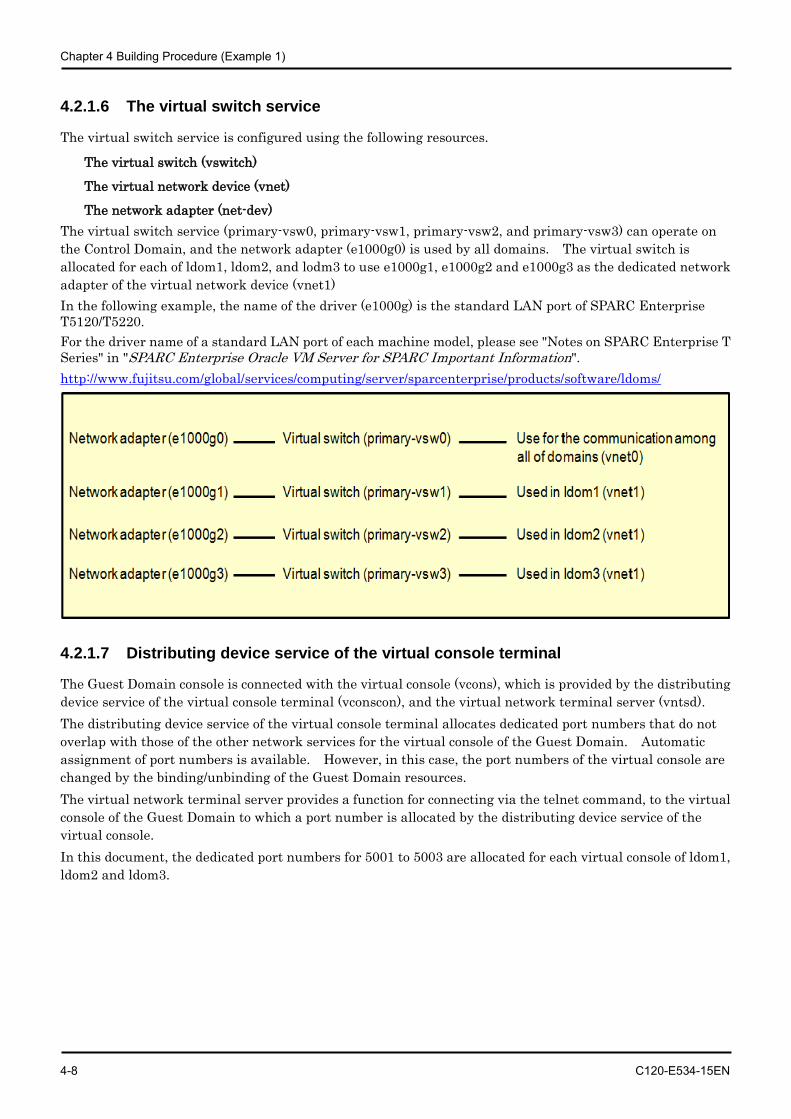
Chapter 4 Building Procedure (Example 1)
4-8 C120-E534-15EN
4.2.1.6 The virtual switch service
The virtual switch service is configured using the following resources.
The virtual switch (vswitch)
The virtual network device (vnet)
The network adapter (net-dev) The virtual switch service (primary-vsw0, primary-vsw1, primary-vsw2, and primary-vsw3) can operate on the Control Domain, and the network adapter (e1000g0) is used by all domains. The virtual switch is allocated for each of ldom1, ldom2, and lodm3 to use e1000g1, e1000g2 and e1000g3 as the dedicated network adapter of the virtual network device (vnet1) In the following example, the name of the driver (e1000g) is the standard LAN port of SPARC Enterprise T5120/T5220. For the driver name of a standard LAN port of each machine model, please see "Notes on SPARC Enterprise T Series" in "SPARC Enterprise Oracle VM Server for SPARC Important Information". http://www.fujitsu.com/global/services/computing/server/sparcenterprise/products/software/ldoms/
4.2.1.7 Distributing device service of the virtual console terminal
The Guest Domain console is connected with the virtual console (vcons), which is provided by the distributing device service of the virtual console terminal (vconscon), and the virtual network terminal server (vntsd). The distributing device service of the virtual console terminal allocates dedicated port numbers that do not overlap with those of the other network services for the virtual console of the Guest Domain. Automatic assignment of port numbers is available. However, in this case, the port numbers of the virtual console are changed by the binding/unbinding of the Guest Domain resources. The virtual network terminal server provides a function for connecting via the telnet command, to the virtual console of the Guest Domain to which a port number is allocated by the distributing device service of the virtual console. In this document, the dedicated port numbers for 5001 to 5003 are allocated for each virtual console of ldom1, ldom2 and ldom3.
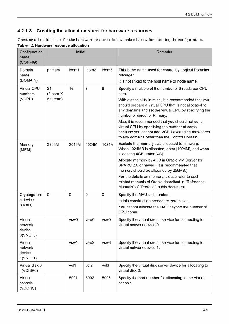
4.2 Building Flow
C120-E534-15EN 4-9
4.2.1.8 Creating the allocation sheet for hardware resources
Creating allocation sheet for the hardware resources below makes it easy for checking the configuration. Table 4.1 Hardware resource allocation
Configuration name (CONFIG)
Initial Remarks
Domain name (DOMAIN)
primary ldom1 ldom2 ldom3 This is the name used for control by Logical Domains Manager. It is not linked to the host name or node name.
Virtual CPU numbers (VCPU)
24 (3 core X 8 thread)
16 8 8 Specify a multiple of the number of threads per CPU core. With extensibility in mind, it is recommended that you should prepare a virtual CPU that is not allocated to any domains and set the virtual CPU by specifying the number of cores for Primary. Also, it is recommended that you should not set a virtual CPU by specifying the number of cores because you cannot add VCPU exceeding max-cores to any domains other than the Control Domain.
Memory (MEM)
3968M 2048M 1024M 1024M Exclude the memory size allocated to firmware. When 1024MB is allocated, enter [1024M], and when allocating 4GB, enter [4G]. Allocate memory by 4GB in Oracle VM Server for SPARC 2.0 or newer. (It is recommended that memory should be allocated by 256MB.) For the details on memory, please refer to each related manuals of Oracle described in "Reference Manuals" of "Preface" in this document.
Cryptographic device *(MAU)
0 0 0 0 Specify the MAU unit number. In this construction procedure zero is set. You cannot allocate the MAU beyond the number of CPU cores.
Virtual network device 0(VNET0)
vsw0 vsw0 vsw0 Specify the virtual switch service for connecting to virtual network device 0.
Virtual network device 1(VNET1)
vsw1 vsw2 vsw3 Specify the virtual switch service for connecting to virtual network device 1.
Virtual disk 0 (VDISK0)
vol1 vol2 vol3 Specify the virtual disk server device for allocating to virtual disk 0.
Virtual console (VCONS)
5001 5002 5003 Specify the port number for allocating to the virtual console.
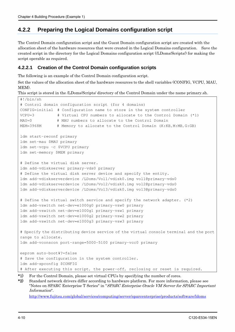
Chapter 4 Building Procedure (Example 1)
4-10 C120-E534-15EN
4.2.2 Preparing the Logical Domains configuration script
The Control Domain configuration script and the Guest Domain configuration script are created with the allocation sheet of the hardware resources that were created in the Logical Domains configuration. Save the created script in the directory for the Logical Domains configuration script (/LDoms/Scripts/) for making the script operable as required.
4.2.2.1 Creation of the Control Domain configuration scripts The following is an example of the Control Domain configuration script. Set the values of the allocation sheet of the hardware resources to the shell variables (CONFIG, VCPU, MAU, MEM). This script is stored in the /LDoms/Scripts/ directory of the Control Domain under the name primary.sh. #!/bin/sh # Control domain configuration script (for 4 domains) CONFIG=initial # Configuration name to store in the system controller VCPU=3 # Virtual CPU numbers to allocate to the Control Domain (*1) MAU=0 # MAU numbers to allocate to the Control Domain MEM=3968M # Memory to allocate to the Control Domain (K:KB,M:MB,G:GB) ldm start-reconf primary ldm set-mau $MAU primary ldm set-vcpu -c $VCPU primary ldm set-memory $MEM primary # Define the virtual disk server. ldm add-vdiskserver primary-vds0 primary # Define the virtual disk server device and specify the entity. ldm add-vdiskserverdevice /LDoms/Vol1/vdisk0.img vol1@primary-vds0 ldm add-vdiskserverdevice /LDoms/Vol2/vdisk0.img vol2@primary-vds0 ldm add-vdiskserverdevice /LDoms/Vol3/vdisk0.img vol3@primary-vds0 # Define the virtual switch service and specify the network adapter. (*2) ldm add-vswitch net-dev=e1000g0 primary-vsw0 primary ldm add-vswitch net-dev=e1000g1 primary-vsw1 primary ldm add-vswitch net-dev=e1000g2 primary-vsw2 primary ldm add-vswitch net-dev=e1000g3 primary-vsw3 primary # Specify the distributing device service of the virtual console terminal and the port range to allocate. ldm add-vconscon port-range=5000-5100 primary-vcc0 primary eeprom auto-boot¥?=false # Save the configuration in the system controller. ldm add-spconfig $CONFIG # After executing this script, the power-off, reclosing or reset is required.
*1) For the Control Domain, please set virtual CPUs by specifying the number of cores. *2) Standard network drivers differ according to hardware platform. For more information, please see
"Notes on SPARC Enterprise T Series" in "SPARC Enterprise Oracle VM Server for SPARC Important Information". http://www.fujitsu.com/global/services/computing/server/sparcenterprise/products/software/ldoms
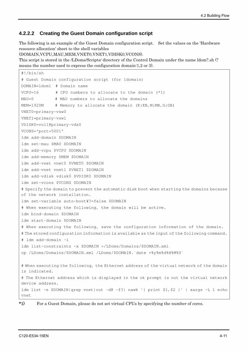
4.2 Building Flow
C120-E534-15EN 4-11
4.2.2.2 Creating the Guest Domain configuration script
The following is an example of the Guest Domain configuration script. Set the values on the 'Hardware resource allocation' sheet to the shell variables (DOMAIN,VCPU,MAU,MEM,VNET0,VNET1,VDISK0,VCONS). This script is stored in the /LDoms/Scripts/ directory of the Control Domain under the name ldom?.sh (? means the number used to express the configuration domain:1,2 or 3). #!/bin/sh
# Guest Domain configuration script (for 1domain)
DOMAIN=ldom1 # Domain name
VCPU=16 # CPU numbers to allocate to the domain (*1)
MAU=0 # MAU numbers to allocate the domains
MEM=1920M # Memory to allocate the domain (K:KB,M:MB,G:GB)
VNET0=primary-vsw0
VNET1=primary-vsw1
VDISK0=vol1@primary-vds0
VCONS="port=5001"
ldm add-domain $DOMAIN
ldm set-mau $MAU $DOMAIN
ldm add-vcpu $VCPU $DOMAIN
ldm add-memory $MEM $DOMAIN
ldm add-vnet vnet0 $VNET0 $DOMAIN
ldm add-vnet vnet1 $VNET1 $DOMAIN
ldm add-vdisk vdisk0 $VDISK0 $DOMAIN
ldm set-vcons $VCONS $DOMAIN
# Specify the domain to prevent the automatic disk boot when starting the domains because of the network installation.
ldm set-variable auto-boot¥?=false $DOMAIN
# When executing the following, the domain will be active.
ldm bind-domain $DOMAIN
ldm start-domain $DOMAIN
# When executing the following, save the configuration information of the domain.
# The stored configuration information is available as the input of the following command.
# ldm add-domain -i
ldm list-constraints -x $DOMAIN >/LDoms/Domains/$DOMAIN.xml
cp /LDoms/Domains/$DOMAIN.xml /LDoms/$DOMAIN.`date +%y%m%d%H%M%S`
# When executing the following, the Ethernet address of the virtual network of the domain is indicated.
# The Ethernet address which is displayed in the ok prompt is not the virtual network device address.
ldm list -e $DOMAIN|grep vnet|cut -d@ -f3| nawk '{ print $1,$2 }' | xargs -L 1 echo vnet
*1) For a Guest Domain, please do not set virtual CPUs by specifying the number of cores.
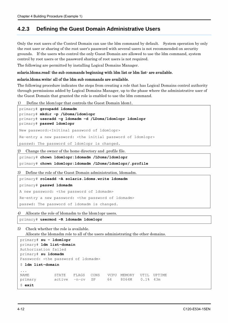
Chapter 4 Building Procedure (Example 1)
4-12 C120-E534-15EN
4.2.3 Defining the Guest Domain Administrative Users
Only the root users of the Control Domain can use the ldm command by default. System operation by only the root user or sharing of the root user's password with several users is not recommended on security grounds. If the users who control the only Guest Domain are allowed to use the ldm command, system control by root users or the password sharing of root users is not required. The following are permitted by installing Logical Domains Manager.
solaris.ldoms.read: the sub commands beginning with ldm list or ldm list- are available.
solaris.ldoms.write: all of the ldm sub commands are available. The following procedure indicates the steps from creating a role that has Logical Domains control authority through permissions added by Logical Domains Manager, up to the phase where the administrative user of the Guest Domain that granted the role is enabled to use the ldm command.
1) Define the ldom1opr that controls the Guest Domain ldom1. primary# groupadd ldomadm primary# mkdir -p /LDoms/ldom1opr primary# useradd -g ldomadm -d /LDoms/ldom1opr ldom1opr primary# passwd ldom1opr
New password:<Initinal password of ldom1opr>
Re-entry a new password: <the initial password of ldom1opr>
passwd: The password of ldom1opr is changed.
2) Change the owner of the home directory and .profile file. primary# chown ldom1opr:ldomadm /LDoms/ldom1opr
primary# chown ldom1opr:ldomadm /LDoms/ldom1opr/.profile
3) Define the role of the Guest Domain administration, ldomadm. primary# roleadd -A solaris.ldoms.write ldomadm
primary# passwd ldomadm
A new password: <the password of ldomadm>
Re-entry a new password: <the password of ldomadm>
passwd: The password of ldomadm is changed.
4) Allocate the role of ldomadm to the ldom1opr users. primary# usermod -R ldomadm ldom1opr
5) Check whether the role is available. Allocate the ldomadm role to all of the users administrating the other domains.
primary# su - ldom1opr primary# ldm list-domain Authorization failed primary# su ldomadm Password: <the password of ldomadm>
$ ldm list-domain
... NAME STATE FLAGS CONS VCPU MEMORY UTIL UPTIME primary active -n-cv SP 64 8064M 0.1% 43m
$ exit
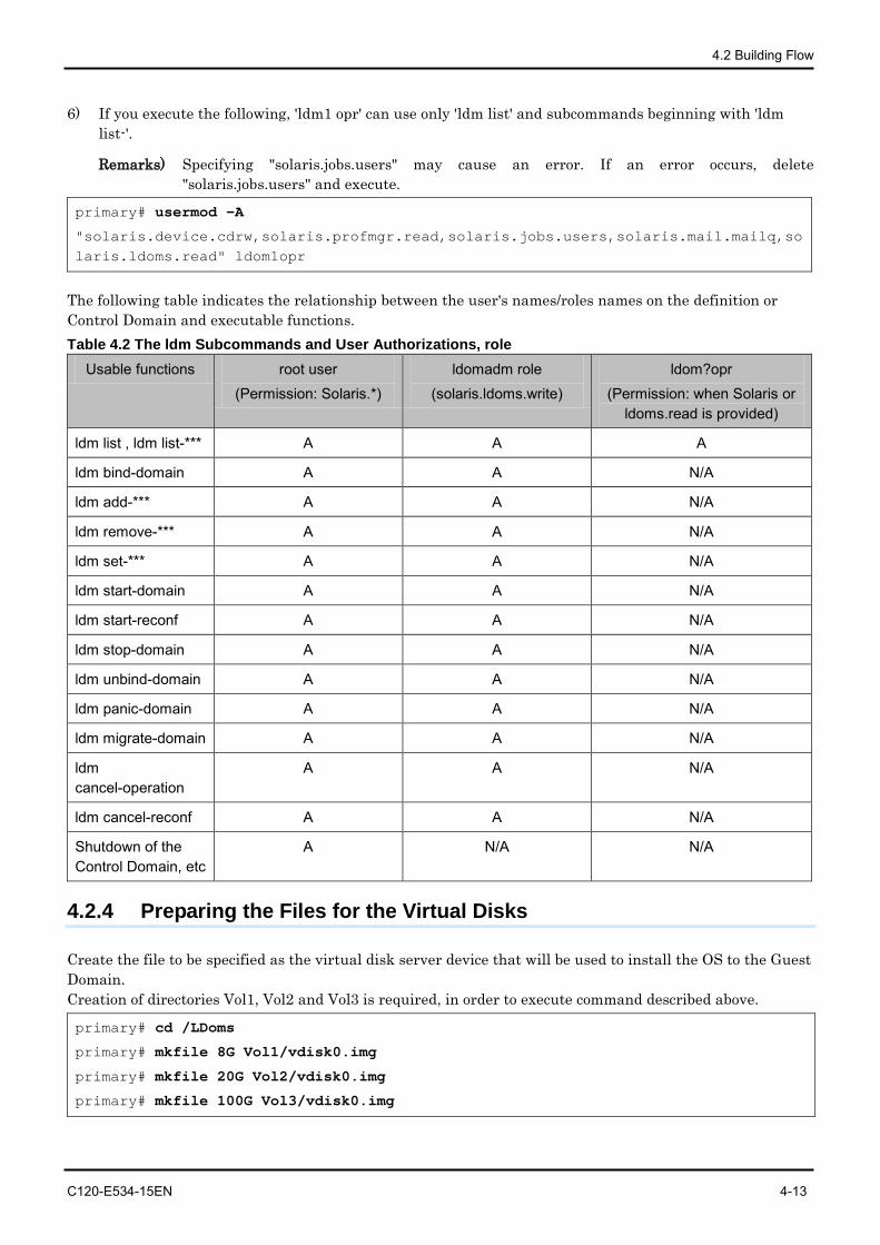
4.2 Building Flow
C120-E534-15EN 4-13
6) If you execute the following, 'ldm1 opr' can use only 'ldm list' and subcommands beginning with 'ldm list-'.
Remarks) Specifying "solaris.jobs.users" may cause an error. If an error occurs, delete "solaris.jobs.users" and execute.
primary# usermod -A
"solaris.device.cdrw,solaris.profmgr.read,solaris.jobs.users,solaris.mail.mailq,solaris.ldoms.read" ldom1opr
The following table indicates the relationship between the user's names/roles names on the definition or Control Domain and executable functions. Table 4.2 The ldm Subcommands and User Authorizations, role
Usable functions root user (Permission: Solaris.*)
ldomadm role (solaris.ldoms.write)
ldom?opr (Permission: when Solaris or
ldoms.read is provided)
ldm list , ldm list-*** A A A
ldm bind-domain A A N/A
ldm add-*** A A N/A
ldm remove-*** A A N/A
ldm set-*** A A N/A
ldm start-domain A A N/A
ldm start-reconf A A N/A
ldm stop-domain A A N/A
ldm unbind-domain A A N/A
ldm panic-domain A A N/A
ldm migrate-domain A A N/A
ldm cancel-operation
A A N/A
ldm cancel-reconf A A N/A
Shutdown of the Control Domain, etc
A N/A N/A
4.2.4 Preparing the Files for the Virtual Disks
Create the file to be specified as the virtual disk server device that will be used to install the OS to the Guest Domain. Creation of directories Vol1, Vol2 and Vol3 is required, in order to execute command described above.
primary# cd /LDoms
primary# mkfile 8G Vol1/vdisk0.img
primary# mkfile 20G Vol2/vdisk0.img
primary# mkfile 100G Vol3/vdisk0.img
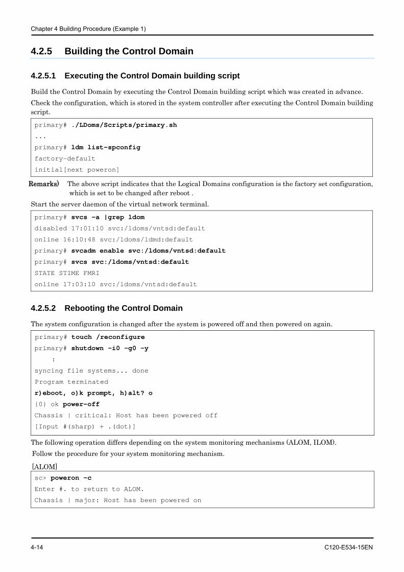
Chapter 4 Building Procedure (Example 1)
4-14 C120-E534-15EN
4.2.5 Building the Control Domain
4.2.5.1 Executing the Control Domain building script
Build the Control Domain by executing the Control Domain building script which was created in advance. Check the configuration, which is stored in the system controller after executing the Control Domain building script.
primary# ./LDoms/Scripts/primary.sh
...
primary# ldm list-spconfig
factory-default
initial[next poweron]
Remarks) The above script indicates that the Logical Domains configuration is the factory set configuration, which is set to be changed after reboot .
Start the server daemon of the virtual network terminal.
primary# svcs -a |grep ldom
disabled 17:01:10 svc:/ldoms/vntsd:default
online 16:10:48 svc:/ldoms/ldmd:default
primary# svcadm enable svc:/ldoms/vntsd:default
primary# svcs svc:/ldoms/vntsd:default
STATE STIME FMRI
online 17:03:10 svc:/ldoms/vntsd:default
4.2.5.2 Rebooting the Control Domain
The system configuration is changed after the system is powered off and then powered on again.
primary# touch /reconfigure
primary# shutdown -i0 -g0 -y
:
syncing file systems... done
Program terminated
r)eboot, o)k prompt, h)alt? o
{0} ok power-off
Chassis | critical: Host has been powered off
[Input #(sharp) + .(dot)]
The following operation differs depending on the system monitoring mechanisms (ALOM, ILOM). Follow the procedure for your system monitoring mechanism.
[ALOM] sc> poweron -c
Enter #. to return to ALOM.
Chassis | major: Host has been powered on
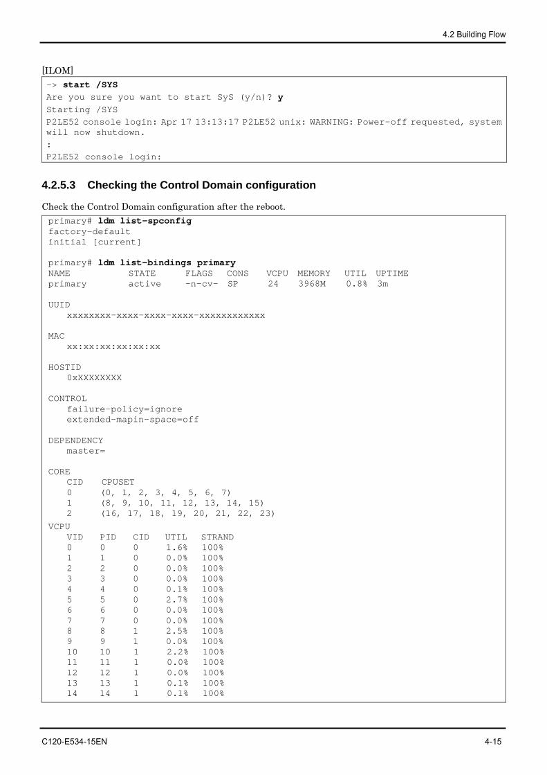
4.2 Building Flow
C120-E534-15EN 4-15
[ILOM] -> start /SYS Are you sure you want to start SyS (y/n)? y Starting /SYS P2LE52 console login: Apr 17 13:13:17 P2LE52 unix: WARNING: Power-off requested, system will now shutdown. : P2LE52 console login:
4.2.5.3 Checking the Control Domain configuration
Check the Control Domain configuration after the reboot. primary# ldm list-spconfig factory-default initial [current] primary# ldm list-bindings primary NAME STATE FLAGS CONS VCPU MEMORY UTIL UPTIME primary active -n-cv- SP 24 3968M 0.8% 3m UUID xxxxxxxx-xxxx-xxxx-xxxx-xxxxxxxxxxxx MAC xx:xx:xx:xx:xx:xx HOSTID 0xXXXXXXXX CONTROL failure-policy=ignore
extended-mapin-space=off DEPENDENCY master= CORE CID CPUSET
0 (0, 1, 2, 3, 4, 5, 6, 7) 1 (8, 9, 10, 11, 12, 13, 14, 15) 2 (16, 17, 18, 19, 20, 21, 22, 23)
VCPU VID PID CID UTIL STRAND 0 0 0 1.6% 100% 1 1 0 0.0% 100% 2 2 0 0.0% 100% 3 3 0 0.0% 100% 4 4 0 0.1% 100% 5 5 0 2.7% 100% 6 6 0 0.0% 100% 7 7 0 0.0% 100% 8 8 1 2.5% 100% 9 9 1 0.0% 100% 10 10 1 2.2% 100% 11 11 1 0.0% 100% 12 12 1 0.0% 100% 13 13 1 0.1% 100% 14 14 1 0.1% 100%
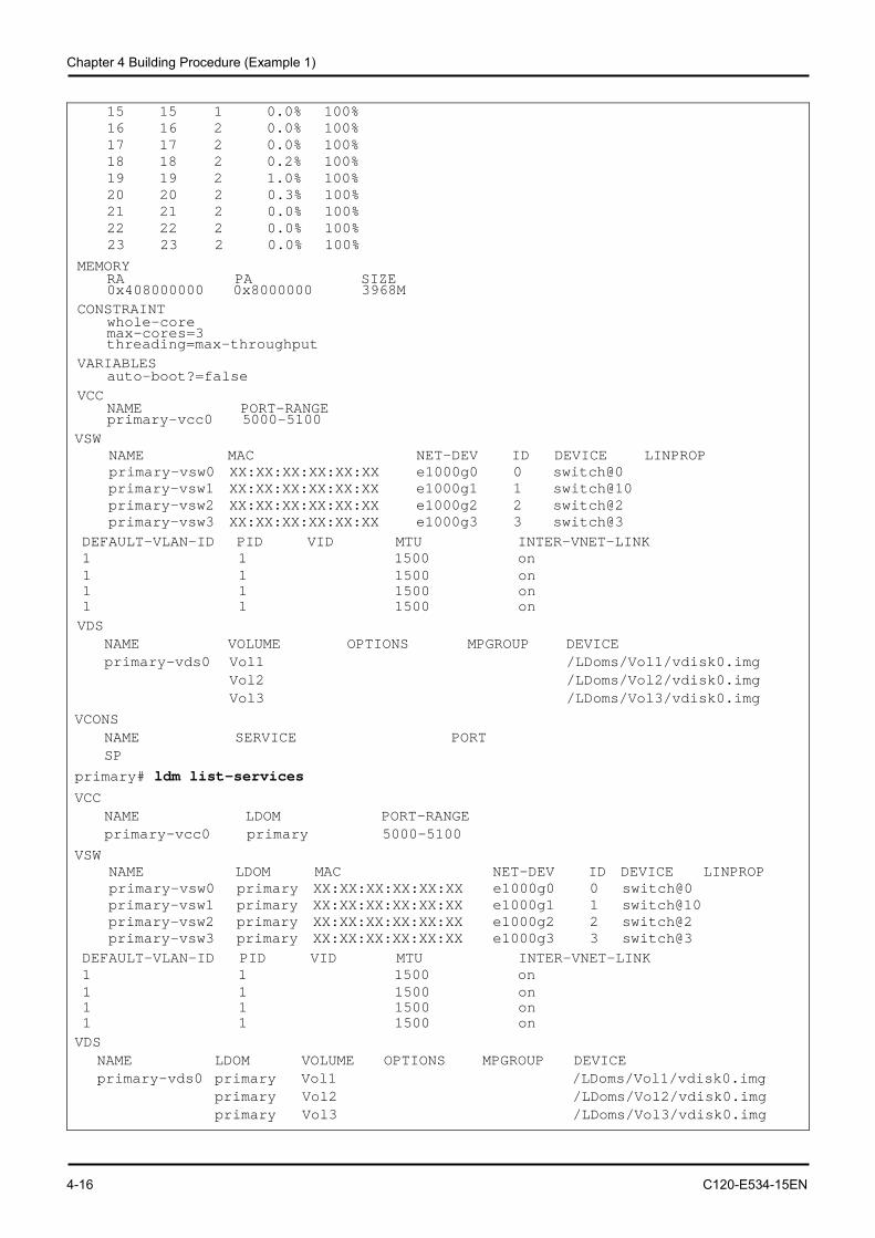
Chapter 4 Building Procedure (Example 1)
4-16 C120-E534-15EN
15 15 1 0.0% 100% 16 16 2 0.0% 100% 17 17 2 0.0% 100% 18 18 2 0.2% 100% 19 19 2 1.0% 100% 20 20 2 0.3% 100% 21 21 2 0.0% 100% 22 22 2 0.0% 100% 23 23 2 0.0% 100%
MEMORY RA PA SIZE 0x408000000 0x8000000 3968M CONSTRAINT whole-core max-cores=3
threading=max-throughput VARIABLES auto-boot?=false VCC NAME PORT-RANGE primary-vcc0 5000-5100 VSW
NAME MAC NET-DEV ID DEVICE LINPROP primary-vsw0 XX:XX:XX:XX:XX:XX e1000g0 0 switch@0
primary-vsw1 XX:XX:XX:XX:XX:XX e1000g1 1 switch@10 primary-vsw2 XX:XX:XX:XX:XX:XX e1000g2 2 switch@2 primary-vsw3 XX:XX:XX:XX:XX:XX e1000g3 3 switch@3
DEFAULT-VLAN-ID PID VID MTU INTER-VNET-LINK 1 1 1500 on 1 1 1500 on 1 1 1500 on 1 1 1500 on VDS NAME VOLUME OPTIONS MPGROUP DEVICE primary-vds0 Vol1 /LDoms/Vol1/vdisk0.img Vol2 /LDoms/Vol2/vdisk0.img Vol3 /LDoms/Vol3/vdisk0.img
VCONS NAME SERVICE PORT SP primary# ldm list-services VCC NAME LDOM PORT-RANGE primary-vcc0 primary 5000-5100
VSW NAME LDOM MAC NET-DEV ID DEVICE LINPROP primary-vsw0 primary XX:XX:XX:XX:XX:XX e1000g0 0 switch@0
primary-vsw1 primary XX:XX:XX:XX:XX:XX e1000g1 1 switch@10 primary-vsw2 primary XX:XX:XX:XX:XX:XX e1000g2 2 switch@2 primary-vsw3 primary XX:XX:XX:XX:XX:XX e1000g3 3 switch@3
DEFAULT-VLAN-ID PID VID MTU INTER-VNET-LINK 1 1 1500 on 1 1 1500 on 1 1 1500 on 1 1 1500 on VDS NAME LDOM VOLUME OPTIONS MPGROUP DEVICE primary-vds0 primary Vol1 /LDoms/Vol1/vdisk0.img primary Vol2 /LDoms/Vol2/vdisk0.img primary Vol3 /LDoms/Vol3/vdisk0.img
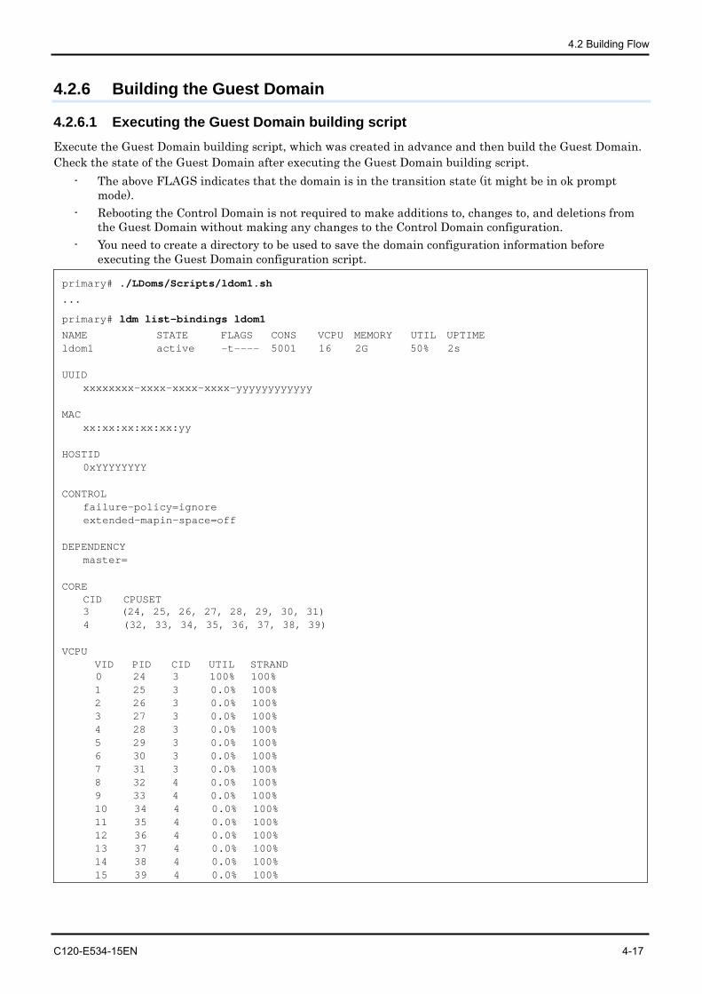
4.2 Building Flow
C120-E534-15EN 4-17
4.2.6 Building the Guest Domain
4.2.6.1 Executing the Guest Domain building script Execute the Guest Domain building script, which was created in advance and then build the Guest Domain. Check the state of the Guest Domain after executing the Guest Domain building script.
- The above FLAGS indicates that the domain is in the transition state (it might be in ok prompt mode).
- Rebooting the Control Domain is not required to make additions to, changes to, and deletions from the Guest Domain without making any changes to the Control Domain configuration.
- You need to create a directory to be used to save the domain configuration information before executing the Guest Domain configuration script.
primary# ./LDoms/Scripts/ldom1.sh
...
primary# ldm list-bindings ldom1
NAME STATE FLAGS CONS VCPU MEMORY UTIL UPTIME ldom1 active -t---- 5001 16 2G 50% 2s UUID xxxxxxxx-xxxx-xxxx-xxxx-yyyyyyyyyyyy MAC xx:xx:xx:xx:xx:yy HOSTID 0xYYYYYYYY CONTROL failure-policy=ignore
extended-mapin-space=off DEPENDENCY master= CORE CID CPUSET 3 (24, 25, 26, 27, 28, 29, 30, 31)
4 (32, 33, 34, 35, 36, 37, 38, 39) VCPU VID PID CID UTIL STRAND
0 24 3 100% 100% 1 25 3 0.0% 100% 2 26 3 0.0% 100% 3 27 3 0.0% 100% 4 28 3 0.0% 100% 5 29 3 0.0% 100% 6 30 3 0.0% 100% 7 31 3 0.0% 100% 8 32 4 0.0% 100% 9 33 4 0.0% 100% 10 34 4 0.0% 100% 11 35 4 0.0% 100% 12 36 4 0.0% 100% 13 37 4 0.0% 100% 14 38 4 0.0% 100% 15 39 4 0.0% 100%
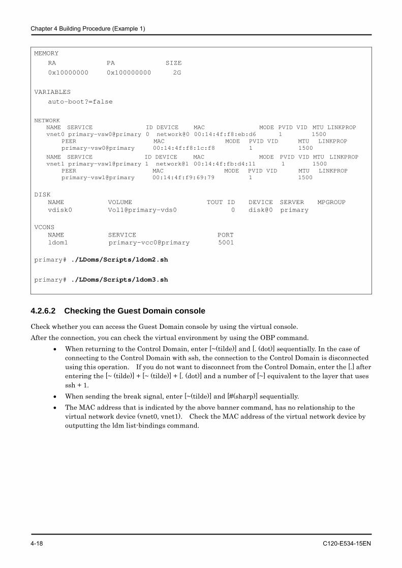
Chapter 4 Building Procedure (Example 1)
4-18 C120-E534-15EN
MEMORY
RA PA SIZE
0x10000000 0x100000000 2G
VARIABLES
auto-boot?=false
NETWORK NAME SERVICE ID DEVICE MAC MODE PVID VID MTU LINKPROP vnet0 primary-vsw0@primary 0 network@0 00:14:4f:f8:eb:d6 1 1500 PEER MAC MODE PVID VID MTU LINKPROP primary-vsw0@primary 00:14:4f:f8:1c:f8 1 1500
NAME SERVICE ID DEVICE MAC MODE PVID VID MTU LINKPROP vnet1 primary-vsw1@primary 1 network@1 00:14:4f:fb:d4:11 1 1500 PEER MAC MODE PVID VID MTU LINKPROP primary-vsw1@primary 00:14:4f:f9:69:79 1 1500
DISK NAME VOLUME TOUT ID DEVICE SERVER MPGROUP vdisk0 Vol1@primary-vds0 0 disk@0 primary
VCONS NAME SERVICE PORT ldom1 primary-vcc0@primary 5001 primary# ./LDoms/Scripts/ldom2.sh
primary# ./LDoms/Scripts/ldom3.sh
4.2.6.2 Checking the Guest Domain console
Check whether you can access the Guest Domain console by using the virtual console. After the connection, you can check the virtual environment by using the OBP command.
• When returning to the Control Domain, enter [~(tilde)] and [. (dot)] sequentially. In the case of connecting to the Control Domain with ssh, the connection to the Control Domain is disconnected using this operation. If you do not want to disconnect from the Control Domain, enter the [.] after entering the [~ (tilde)] + [~ (tilde)] + [. (dot)] and a number of [~] equivalent to the layer that uses ssh + 1.
• When sending the break signal, enter [~(tilde)] and [#(sharp)] sequentially. • The MAC address that is indicated by the above banner command, has no relationship to the
virtual network device (vnet0, vnet1). Check the MAC address of the virtual network device by outputting the ldm list-bindings command.
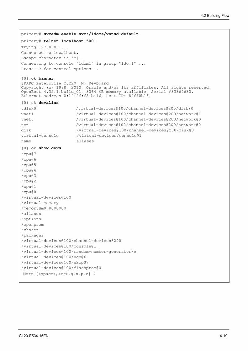
4.2 Building Flow
C120-E534-15EN 4-19
primary# svcadm enable svc:/ldoms/vntsd:default
primary# telnet localhost 5001 Trying 127.0.0.1... Connected to localhost. Escape character is '^]'. Connecting to console "ldom1" in group "ldom1" ... Press ~? for control options .. {0} ok banner SPARC Enterprise T5220, No Keyboard Copyright (c) 1998, 2010, Oracle and/or its affiliates. All rights reserved. OpenBoot 4.32.1.build_01, 8064 MB memory available, Serial #83364630. Ethernet address 0:14:4f:f8:b:16, Host ID: 84f80b16.
{0} ok devalias vdisk0 /virtual-devices@100/channel-devices@200/disk@0 vnet1 /virtual-devices@100/channel-devices@200/network@1 vnet0 /virtual-devices@100/channel-devices@200/network@0 net /virtual-devices@100/channel-devices@200/network@0 disk /virtual-devices@100/channel-devices@200/disk@0 virtual-console /virtual-devices/console@1 name aliases
{0} ok show-devs /cpu@7 /cpu@6 /cpu@5 /cpu@4 /cpu@3 /cpu@2 /cpu@1 /cpu@0 /virtual-devices@100 /virtual-memory /memory@m0,8000000 /aliases /options /openprom /chosen /packages /virtual-devices@100/channel-devices@200 /virtual-devices@100/console@1 /virtual-devices@100/random-number-generator@e /virtual-devices@100/ncp@6 /virtual-devices@100/n2cp@7 /virtual-devices@100/flashprom@0
More [<space>,<cr>,q,n,p,c] ?
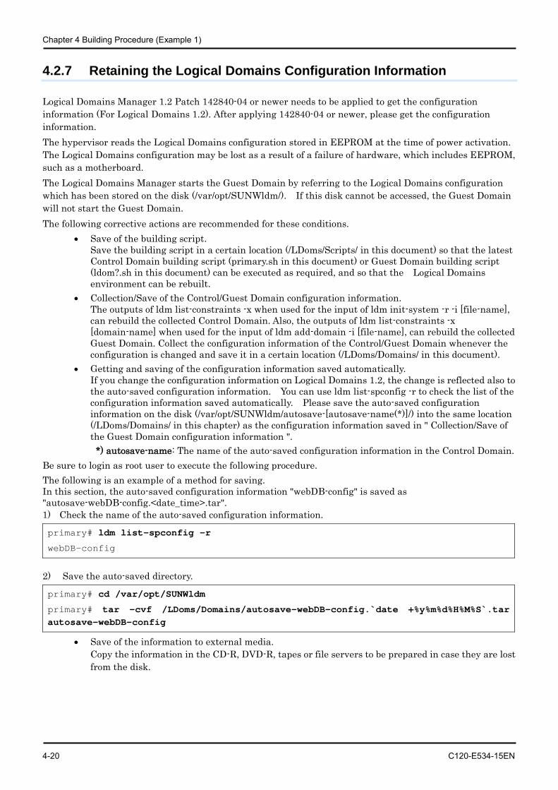
Chapter 4 Building Procedure (Example 1)
4-20 C120-E534-15EN
4.2.7 Retaining the Logical Domains Configuration Information
Logical Domains Manager 1.2 Patch 142840-04 or newer needs to be applied to get the configuration information (For Logical Domains 1.2). After applying 142840-04 or newer, please get the configuration information. The hypervisor reads the Logical Domains configuration stored in EEPROM at the time of power activation. The Logical Domains configuration may be lost as a result of a failure of hardware, which includes EEPROM, such as a motherboard. The Logical Domains Manager starts the Guest Domain by referring to the Logical Domains configuration which has been stored on the disk (/var/opt/SUNWldm/). If this disk cannot be accessed, the Guest Domain will not start the Guest Domain. The following corrective actions are recommended for these conditions.
• Save of the building script. Save the building script in a certain location (/LDoms/Scripts/ in this document) so that the latest Control Domain building script (primary.sh in this document) or Guest Domain building script (ldom?.sh in this document) can be executed as required, and so that the Logical Domains environment can be rebuilt.
• Collection/Save of the Control/Guest Domain configuration information. The outputs of ldm list-constraints -x when used for the input of ldm init-system -r -i [file-name], can rebuild the collected Control Domain. Also, the outputs of ldm list-constraints -x [domain-name] when used for the input of ldm add-domain -i [file-name], can rebuild the collected Guest Domain. Collect the configuration information of the Control/Guest Domain whenever the configuration is changed and save it in a certain location (/LDoms/Domains/ in this document).
• Getting and saving of the configuration information saved automatically. If you change the configuration information on Logical Domains 1.2, the change is reflected also to the auto-saved configuration information. You can use ldm list-spconfig -r to check the list of the configuration information saved automatically. Please save the auto-saved configuration information on the disk (/var/opt/SUNWldm/autosave-[autosave-name(*)]/) into the same location (/LDoms/Domains/ in this chapter) as the configuration information saved in " Collection/Save of the Guest Domain configuration information ".
*) autosave-name: The name of the auto-saved configuration information in the Control Domain. Be sure to login as root user to execute the following procedure. The following is an example of a method for saving. In this section, the auto-saved configuration information "webDB-config" is saved as "autosave-webDB-config.<date_time>.tar". 1) Check the name of the auto-saved configuration information.
primary# ldm list-spconfig -r
webDB-config
2) Save the auto-saved directory.
primary# cd /var/opt/SUNWldm
primary# tar -cvf /LDoms/Domains/autosave-webDB-config.`date +%y%m%d%H%M%S`.tar autosave-webDB-config
• Save of the information to external media. Copy the information in the CD-R, DVD-R, tapes or file servers to be prepared in case they are lost from the disk.
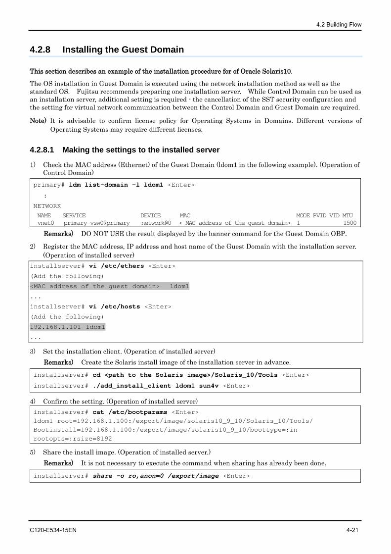
4.2 Building Flow
C120-E534-15EN 4-21
4.2.8 Installing the Guest Domain
This section describes an example of the installation procedure for of Oracle Solaris10.
The OS installation in Guest Domain is executed using the network installation method as well as the standard OS. Fujitsu recommends preparing one installation server. While Control Domain can be used as an installation server, additional setting is required - the cancellation of the SST security configuration and the setting for virtual network communication between the Control Domain and Guest Domain are required.
Note) It is advisable to confirm license policy for Operating Systems in Domains. Different versions of Operating Systems may require different licenses.
4.2.8.1 Making the settings to the installed server
1) Check the MAC address (Ethernet) of the Guest Domain (ldom1 in the following example). (Operation of Control Domain)
primary# ldm list-domain -l ldom1 <Enter>
:
NETWORK
NAME SERVICE DEVICE MAC MODE PVID VID MTU vnet0 primary-vsw0@primary network@0 < MAC address of the guest domain> 1 1500
Remarks) DO NOT USE the result displayed by the banner command for the Guest Domain OBP.
2) Register the MAC address, IP address and host name of the Guest Domain with the installation server. (Operation of installed server)
installserver# vi /etc/ethers <Enter>
(Add the following)
<MAC address of the guest domain> ldom1
...
installserver# vi /etc/hosts <Enter>
(Add the following)
192.168.1.101 ldom1
...
3) Set the installation client. (Operation of installed server) Remarks) Create the Solaris install image of the installation server in advance.
installserver# cd <path to the Solaris image>/Solaris_10/Tools <Enter>
installserver# ./add_install_client ldom1 sun4v <Enter>
4) Confirm the setting. (Operation of installed server) installserver# cat /etc/bootparams <Enter> ldom1 root=192.168.1.100:/export/image/solaris10_9_10/Solaris_10/Tools/ Bootinstall=192.168.1.100:/export/image/solaris10_9_10/boottype=:in rootopts=:rsize=8192
5) Share the install image. (Operation of installed server.) Remarks) It is not necessary to execute the command when sharing has already been done.
installserver# share -o ro,anon=0 /export/image <Enter>
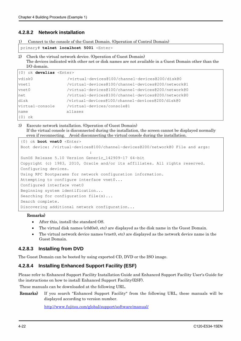
Chapter 4 Building Procedure (Example 1)
4-22 C120-E534-15EN
4.2.8.2 Network installation
1) Connect to the console of the Guest Domain. (Operation of Control Domain) primary# telnet localhost 5001 <Enter>
2) Check the virtual network device. (Operation of Guest Domain) The devices indicated with other net or disk names are not available in a Guest Domain other than the I/O domain.
{0} ok devalias <Enter>
vdisk0 /virtual-devices@100/channel-devices@200/disk@0 vnet1 /virtual-devices@100/channel-devices@200/network@1 vnet0 /virtual-devices@100/channel-devices@200/network@0 net /virtual-devices@100/channel-devices@200/network@0 disk /virtual-devices@100/channel-devices@200/disk@0 virtual-console /virtual-devices/console@1 name aliases {0} ok
3) Execute network installation. (Operation of Guest Domain) If the virtual console is disconnected during the installation, the screen cannot be displayed normally even if reconnecting. Avoid disconnecting the virtual console during the installation.
{0} ok boot vnet0 <Enter> Boot device: /virtual-devices@100/channel-devices@200/network@0 File and args:
: SunOS Release 5.10 Version Generic_142909-17 64-bit Copyright (c) 1983, 2010, Oracle and/or its affiliates. All rights reserved. Configuring devices. Using RPC Bootparams for network configuration information. Attempting to configure interface vnet0... Configured interface vnet0 Beginning system identification... Searching for configuration file(s)... Search complete. Discovering additional network configuration...
Remarks) • After this, install the standard OS. • The virtual disk names (c0d0s0, etc) are displayed as the disk name in the Guest Domain. • The virtual network device names (vnet0, etc) are displayed as the network device name in the
Guest Domain.
4.2.8.3 Installing from DVD The Guest Domain can be booted by using exported CD, DVD or the ISO image.
4.2.8.4 Installing Enhanced Support Facility (ESF)
Please refer to Enhanced Support Facility Installation Guide and Enhanced Support Facility User's Guide for the instructions on how to install Enhanced Support Facility(ESF). These manuals can be downloaded at the following URL. Remarks) If you search "Enhanced Support Facility" from the following URL, these manuals will be
displayed according to version number.
http://www.fujitsu.com/global/support/software/manual/
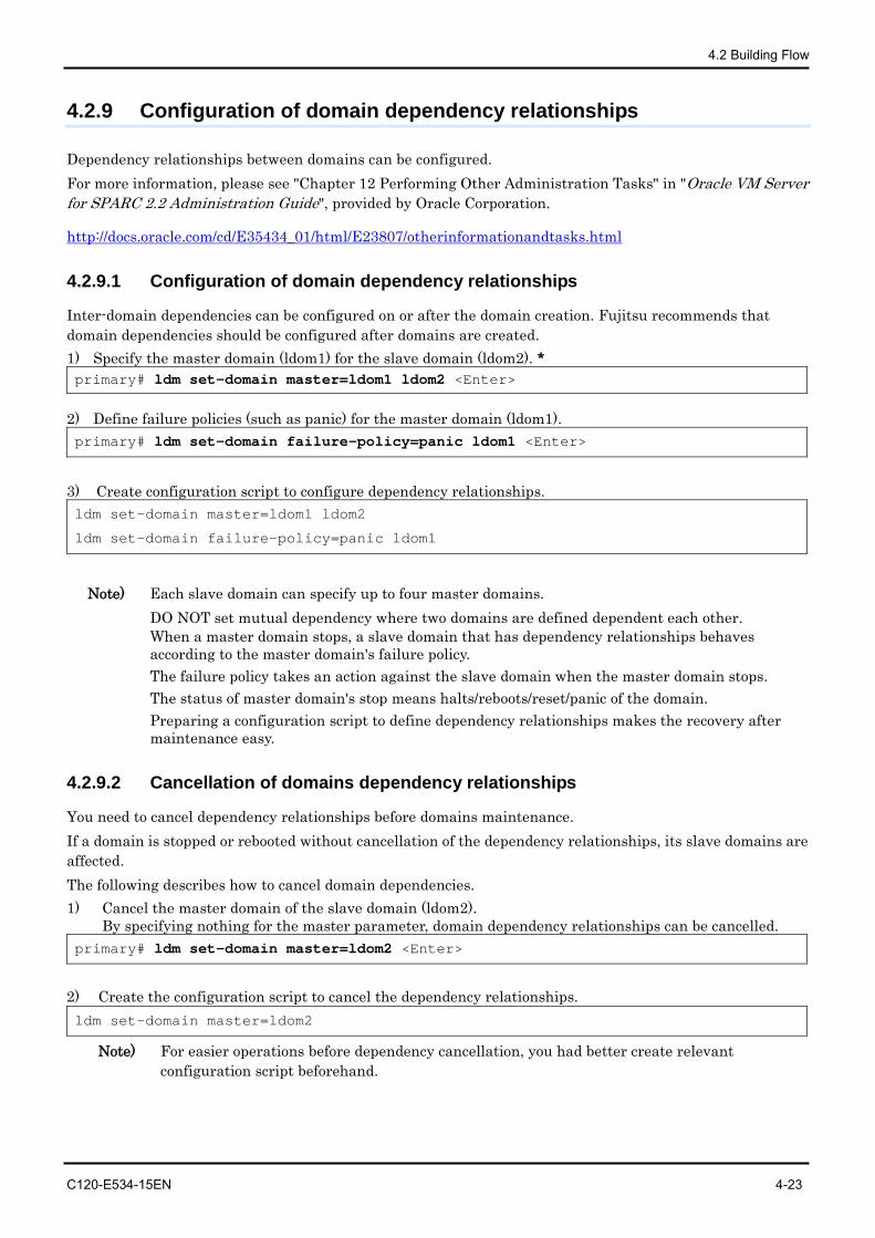
4.2 Building Flow
C120-E534-15EN 4-23
4.2.9 Configuration of domain dependency relationships
Dependency relationships between domains can be configured. For more information, please see "Chapter 12 Performing Other Administration Tasks" in "Oracle VM Server for SPARC 2.2 Administration Guide", provided by Oracle Corporation.
http://docs.oracle.com/cd/E35434_01/html/E23807/otherinformationandtasks.html
4.2.9.1 Configuration of domain dependency relationships
Inter-domain dependencies can be configured on or after the domain creation. Fujitsu recommends that domain dependencies should be configured after domains are created. 1) Specify the master domain (ldom1) for the slave domain (ldom2). * primary# ldm set-domain master=ldom1 ldom2 <Enter>
2) Define failure policies (such as panic) for the master domain (ldom1). primary# ldm set-domain failure-policy=panic ldom1 <Enter>
3) Create configuration script to configure dependency relationships. ldm set-domain master=ldom1 ldom2
ldm set-domain failure-policy=panic ldom1
Note) Each slave domain can specify up to four master domains.
DO NOT set mutual dependency where two domains are defined dependent each other. When a master domain stops, a slave domain that has dependency relationships behaves according to the master domain's failure policy. The failure policy takes an action against the slave domain when the master domain stops. The status of master domain's stop means halts/reboots/reset/panic of the domain. Preparing a configuration script to define dependency relationships makes the recovery after maintenance easy.
4.2.9.2 Cancellation of domains dependency relationships
You need to cancel dependency relationships before domains maintenance. If a domain is stopped or rebooted without cancellation of the dependency relationships, its slave domains are affected. The following describes how to cancel domain dependencies. 1) Cancel the master domain of the slave domain (ldom2).
By specifying nothing for the master parameter, domain dependency relationships can be cancelled. primary# ldm set-domain master=ldom2 <Enter>
2) Create the configuration script to cancel the dependency relationships. ldm set-domain master=ldom2
Note) For easier operations before dependency cancellation, you had better create relevant configuration script beforehand.
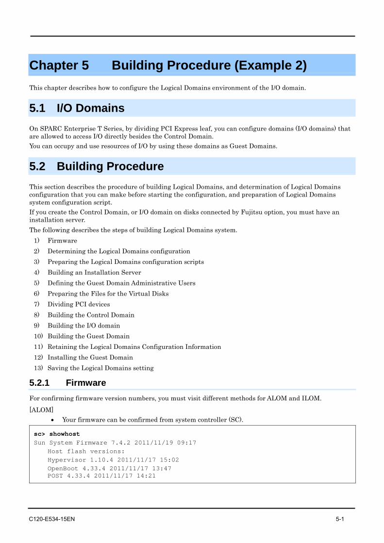
C120-E534-15EN 5-1
Chapter 5 Building Procedure (Example 2) This chapter describes how to configure the Logical Domains environment of the I/O domain.
5.1 I/O Domains On SPARC Enterprise T Series, by dividing PCI Express leaf, you can configure domains (I/O domains) that are allowed to access I/O directly besides the Control Domain. You can occupy and use resources of I/O by using these domains as Guest Domains.
5.2 Building Procedure This section describes the procedure of building Logical Domains, and determination of Logical Domains configuration that you can make before starting the configuration, and preparation of Logical Domains system configuration script. If you create the Control Domain, or I/O domain on disks connected by Fujitsu option, you must have an installation server. The following describes the steps of building Logical Domains system.
1) Firmware 2) Determining the Logical Domains configuration 3) Preparing the Logical Domains configuration scripts 4) Building an Installation Server 5) Defining the Guest Domain Administrative Users 6) Preparing the Files for the Virtual Disks 7) Dividing PCI devices 8) Building the Control Domain 9) Building the I/O domain 10) Building the Guest Domain 11) Retaining the Logical Domains Configuration Information 12) Installing the Guest Domain 13) Saving the Logical Domains setting
5.2.1 Firmware For confirming firmware version numbers, you must visit different methods for ALOM and ILOM.
[ALOM] • Your firmware can be confirmed from system controller (SC).
sc> showhost Sun System Firmware 7.4.2 2011/11/19 09:17
Host flash versions: Hypervisor 1.10.4 2011/11/17 15:02 OpenBoot 4.33.4 2011/11/17 13:47 POST 4.33.4 2011/11/17 14:21
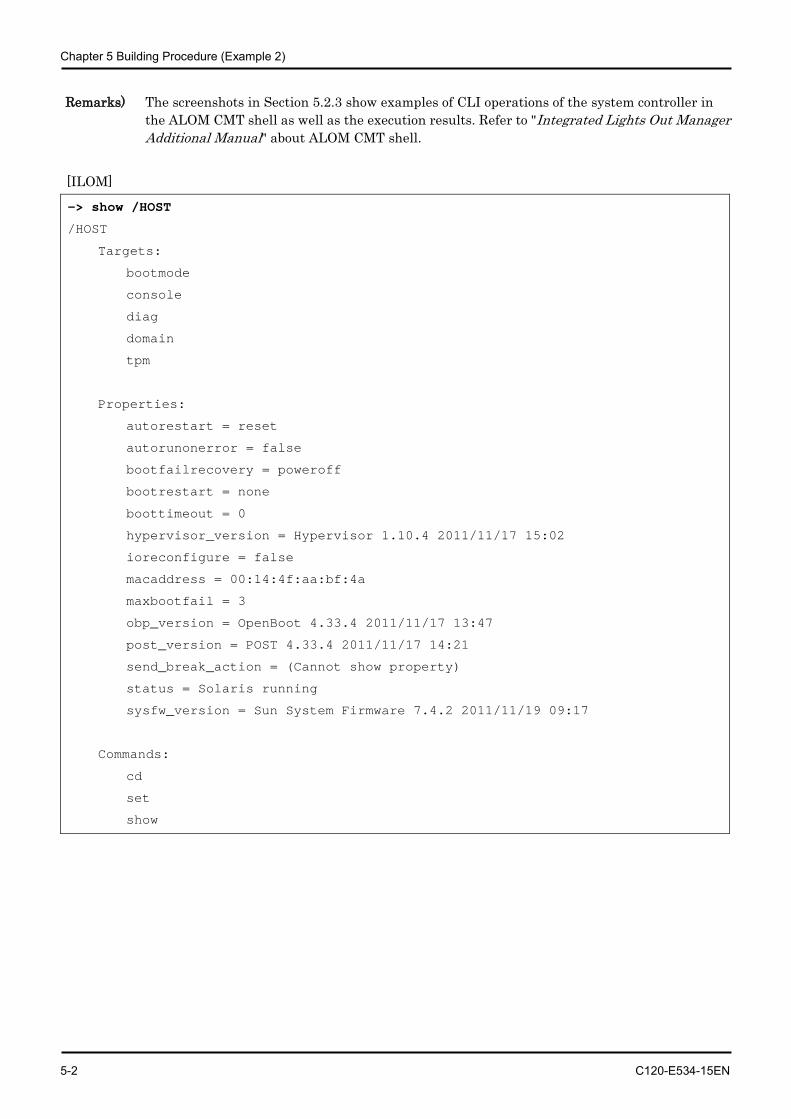
Chapter 5 Building Procedure (Example 2)
5-2 C120-E534-15EN
Remarks) The screenshots in Section 5.2.3 show examples of CLI operations of the system controller in the ALOM CMT shell as well as the execution results. Refer to "Integrated Lights Out Manager Additional Manual" about ALOM CMT shell.
[ILOM]
-> show /HOST
/HOST
Targets:
bootmode
console
diag
domain
tpm
Properties:
autorestart = reset
autorunonerror = false
bootfailrecovery = poweroff
bootrestart = none
boottimeout = 0
hypervisor_version = Hypervisor 1.10.4 2011/11/17 15:02
ioreconfigure = false
macaddress = 00:14:4f:aa:bf:4a
maxbootfail = 3
obp_version = OpenBoot 4.33.4 2011/11/17 13:47
post_version = POST 4.33.4 2011/11/17 14:21
send_break_action = (Cannot show property)
status = Solaris running
sysfw_version = Sun System Firmware 7.4.2 2011/11/19 09:17
Commands:
cd
set
show
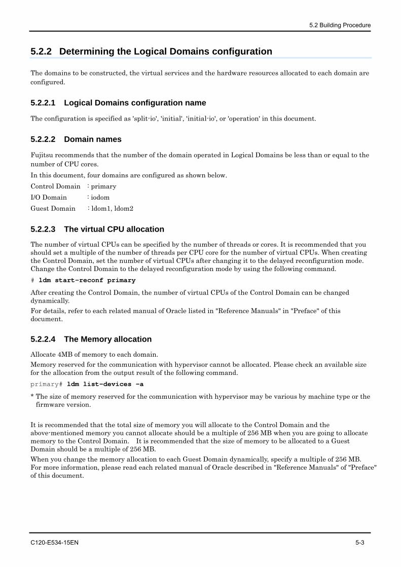
5.2 Building Procedure
C120-E534-15EN 5-3
5.2.2 Determining the Logical Domains configuration
The domains to be constructed, the virtual services and the hardware resources allocated to each domain are configured.
5.2.2.1 Logical Domains configuration name
The configuration is specified as 'split-io', 'initial', 'initial-io', or 'operation' in this document.
5.2.2.2 Domain names
Fujitsu recommends that the number of the domain operated in Logical Domains be less than or equal to the number of CPU cores. In this document, four domains are configured as shown below. Control Domain : primary I/O Domain : iodom Guest Domain : ldom1, ldom2
5.2.2.3 The virtual CPU allocation
The number of virtual CPUs can be specified by the number of threads or cores. It is recommended that you should set a multiple of the number of threads per CPU core for the number of virtual CPUs. When creating the Control Domain, set the number of virtual CPUs after changing it to the delayed reconfiguration mode. Change the Control Domain to the delayed reconfiguration mode by using the following command. # ldm start-reconf primary
After creating the Control Domain, the number of virtual CPUs of the Control Domain can be changed dynamically. For details, refer to each related manual of Oracle listed in "Reference Manuals" in "Preface" of this document.
5.2.2.4 The Memory allocation
Allocate 4MB of memory to each domain. Memory reserved for the communication with hypervisor cannot be allocated. Please check an available size for the allocation from the output result of the following command. primary# ldm list-devices -a
* The size of memory reserved for the communication with hypervisor may be various by machine type or the firmware version.
It is recommended that the total size of memory you will allocate to the Control Domain and the above-mentioned memory you cannot allocate should be a multiple of 256 MB when you are going to allocate memory to the Control Domain. It is recommended that the size of memory to be allocated to a Guest Domain should be a multiple of 256 MB. When you change the memory allocation to each Guest Domain dynamically, specify a multiple of 256 MB. For more information, please read each related manual of Oracle described in "Reference Manuals" of "Preface" of this document.
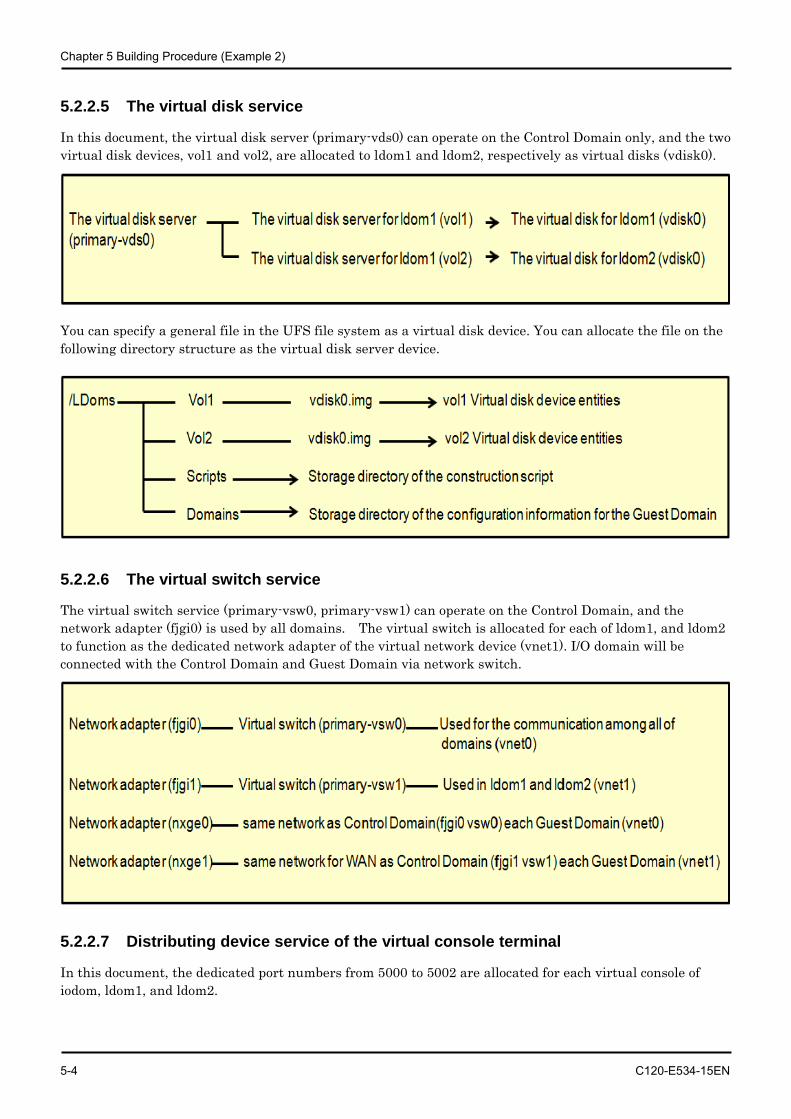
Chapter 5 Building Procedure (Example 2)
5-4 C120-E534-15EN
5.2.2.5 The virtual disk service
In this document, the virtual disk server (primary-vds0) can operate on the Control Domain only, and the two virtual disk devices, vol1 and vol2, are allocated to ldom1 and ldom2, respectively as virtual disks (vdisk0).
You can specify a general file in the UFS file system as a virtual disk device. You can allocate the file on the following directory structure as the virtual disk server device.
5.2.2.6 The virtual switch service
The virtual switch service (primary-vsw0, primary-vsw1) can operate on the Control Domain, and the network adapter (fjgi0) is used by all domains. The virtual switch is allocated for each of ldom1, and ldom2 to function as the dedicated network adapter of the virtual network device (vnet1). I/O domain will be connected with the Control Domain and Guest Domain via network switch.
5.2.2.7 Distributing device service of the virtual console terminal
In this document, the dedicated port numbers from 5000 to 5002 are allocated for each virtual console of iodom, ldom1, and ldom2.
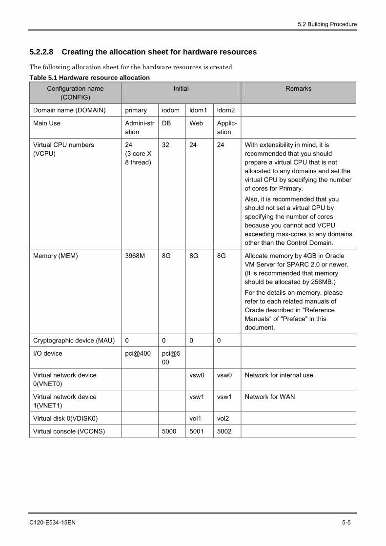
5.2 Building Procedure
C120-E534-15EN 5-5
5.2.2.8 Creating the allocation sheet for hardware resources
The following allocation sheet for the hardware resources is created. Table 5.1 Hardware resource allocation
Configuration name (CONFIG)
Initial Remarks
Domain name (DOMAIN) primary iodom ldom1 ldom2
Main Use Admini-stration
DB Web Applic-ation
Virtual CPU numbers (VCPU)
24 (3 core X 8 thread)
32 24 24 With extensibility in mind, it is recommended that you should prepare a virtual CPU that is not allocated to any domains and set the virtual CPU by specifying the number of cores for Primary. Also, it is recommended that you should not set a virtual CPU by specifying the number of cores because you cannot add VCPU exceeding max-cores to any domains other than the Control Domain.
Memory (MEM) 3968M 8G 8G 8G Allocate memory by 4GB in Oracle VM Server for SPARC 2.0 or newer. (It is recommended that memory should be allocated by 256MB.) For the details on memory, please refer to each related manuals of Oracle described in "Reference Manuals" of "Preface" in this document.
Cryptographic device (MAU) 0 0 0 0
I/O device pci@400 pci@500
Virtual network device 0(VNET0)
vsw0 vsw0 Network for internal use
Virtual network device 1(VNET1)
vsw1 vsw1 Network for WAN
Virtual disk 0(VDISK0) vol1 vol2
Virtual console (VCONS) 5000 5001 5002
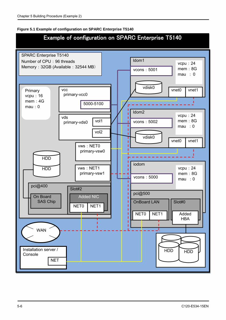
Chapter 5 Building Procedure (Example 2)
5-6 C120-E534-15EN
Figure 5.1 Example of configuration on SPARC Enterprise T5140
vcc primary-vcc0
Example of configuration on SPARC Enterprise T5140
SPARC Enterprise T5140 Number of CPU:96 threads Memory:32GB (Available:32544 MB)
Primary vcpu:16 mem:4G mau:0
vds primary-vds0 vol1
vol2
vws:NET1 primary-vsw1
pci@400
On Board SAS Chip
Slot#2
Added NIC
NET0 NET1
HDD
5000-5100
HDD iodom
pci@500
vcons:5000
vcpu:24 mem:8G mau :0
OnBoard LAN Slot#0
NET0 NET1 Added HBA
HDD HDD Installation server / Console
NET
ldom1
vnet0 vnet1 vdisk0
vcons:5001 vcpu:24 mem:8G mau : 0
ldom2
vnet0 vnet1 vdisk0
vcons:5002 vcpu:24 mem:8G mau :0
vws:NET0 primary-vsw0
WAN
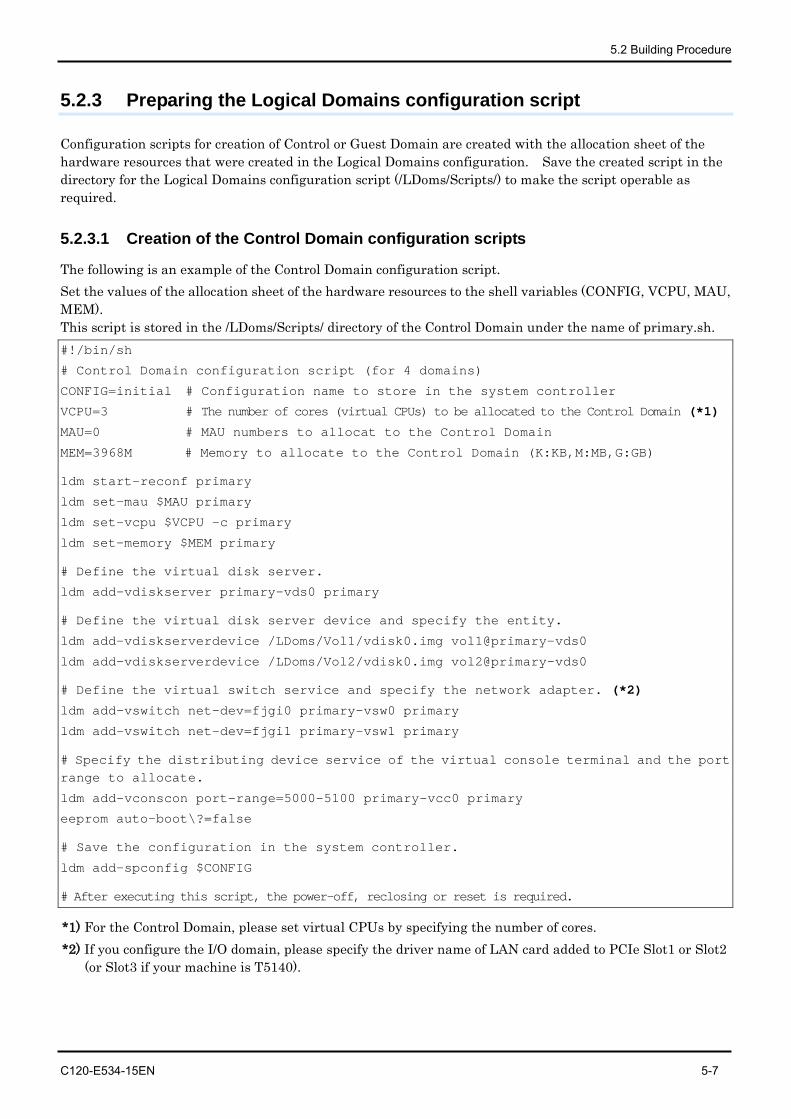
5.2 Building Procedure
C120-E534-15EN 5-7
5.2.3 Preparing the Logical Domains configuration script
Configuration scripts for creation of Control or Guest Domain are created with the allocation sheet of the hardware resources that were created in the Logical Domains configuration. Save the created script in the directory for the Logical Domains configuration script (/LDoms/Scripts/) to make the script operable as required.
5.2.3.1 Creation of the Control Domain configuration scripts
The following is an example of the Control Domain configuration script. Set the values of the allocation sheet of the hardware resources to the shell variables (CONFIG, VCPU, MAU, MEM). This script is stored in the /LDoms/Scripts/ directory of the Control Domain under the name of primary.sh. #!/bin/sh
# Control Domain configuration script (for 4 domains)
CONFIG=initial # Configuration name to store in the system controller
VCPU=3 # The number of cores (virtual CPUs) to be allocated to the Control Domain (*1)
MAU=0 # MAU numbers to allocat to the Control Domain
MEM=3968M # Memory to allocate to the Control Domain (K:KB,M:MB,G:GB)
ldm start-reconf primary
ldm set-mau $MAU primary
ldm set-vcpu $VCPU -c primary
ldm set-memory $MEM primary
# Define the virtual disk server.
ldm add-vdiskserver primary-vds0 primary
# Define the virtual disk server device and specify the entity.
ldm add-vdiskserverdevice /LDoms/Vol1/vdisk0.img vol1@primary-vds0
ldm add-vdiskserverdevice /LDoms/Vol2/vdisk0.img vol2@primary-vds0
# Define the virtual switch service and specify the network adapter. (*2)
ldm add-vswitch net-dev=fjgi0 primary-vsw0 primary
ldm add-vswitch net-dev=fjgi1 primary-vsw1 primary
# Specify the distributing device service of the virtual console terminal and the port range to allocate.
ldm add-vconscon port-range=5000-5100 primary-vcc0 primary
eeprom auto-boot\?=false
# Save the configuration in the system controller.
ldm add-spconfig $CONFIG
# After executing this script, the power-off, reclosing or reset is required.
*1) For the Control Domain, please set virtual CPUs by specifying the number of cores. *2) If you configure the I/O domain, please specify the driver name of LAN card added to PCIe Slot1 or Slot2
(or Slot3 if your machine is T5140).
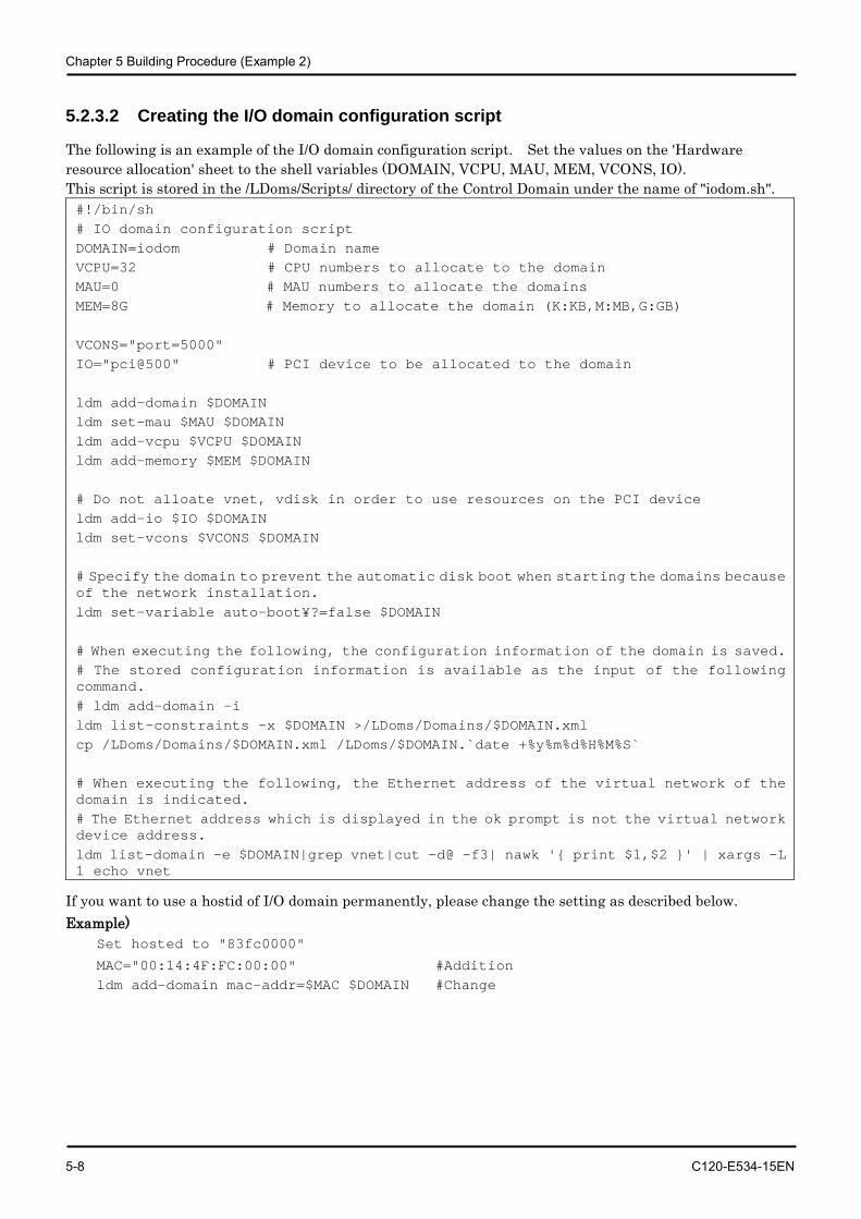
Chapter 5 Building Procedure (Example 2)
5-8 C120-E534-15EN
5.2.3.2 Creating the I/O domain configuration script
The following is an example of the I/O domain configuration script. Set the values on the 'Hardware resource allocation' sheet to the shell variables (DOMAIN, VCPU, MAU, MEM, VCONS, IO). This script is stored in the /LDoms/Scripts/ directory of the Control Domain under the name of "iodom.sh". #!/bin/sh # IO domain configuration script DOMAIN=iodom # Domain name VCPU=32 # CPU numbers to allocate to the domain MAU=0 # MAU numbers to allocate the domains MEM=8G # Memory to allocate the domain (K:KB,M:MB,G:GB) VCONS="port=5000" IO="pci@500" # PCI device to be allocated to the domain ldm add-domain $DOMAIN ldm set-mau $MAU $DOMAIN ldm add-vcpu $VCPU $DOMAIN ldm add-memory $MEM $DOMAIN # Do not alloate vnet, vdisk in order to use resources on the PCI device ldm add-io $IO $DOMAIN ldm set-vcons $VCONS $DOMAIN # Specify the domain to prevent the automatic disk boot when starting the domains because of the network installation. ldm set-variable auto-boot¥?=false $DOMAIN # When executing the following, the configuration information of the domain is saved. # The stored configuration information is available as the input of the following command. # ldm add-domain -i ldm list-constraints -x $DOMAIN >/LDoms/Domains/$DOMAIN.xml cp /LDoms/Domains/$DOMAIN.xml /LDoms/$DOMAIN.`date +%y%m%d%H%M%S` # When executing the following, the Ethernet address of the virtual network of the domain is indicated. # The Ethernet address which is displayed in the ok prompt is not the virtual network device address. ldm list-domain -e $DOMAIN|grep vnet|cut -d@ -f3| nawk '{ print $1,$2 }' | xargs -L 1 echo vnet
If you want to use a hostid of I/O domain permanently, please change the setting as described below. Example)
Set hosted to "83fc0000"
MAC="00:14:4F:FC:00:00" #Addition ldm add-domain mac-addr=$MAC $DOMAIN #Change
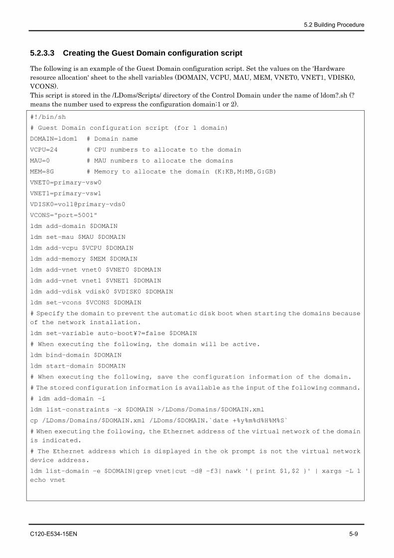
5.2 Building Procedure
C120-E534-15EN 5-9
5.2.3.3 Creating the Guest Domain configuration script
The following is an example of the Guest Domain configuration script. Set the values on the 'Hardware resource allocation' sheet to the shell variables (DOMAIN, VCPU, MAU, MEM, VNET0, VNET1, VDISK0, VCONS). This script is stored in the /LDoms/Scripts/ directory of the Control Domain under the name of ldom?.sh (? means the number used to express the configuration domain:1 or 2).
#!/bin/sh
# Guest Domain configuration script (for 1 domain)
DOMAIN=ldom1 # Domain name
VCPU=24 # CPU numbers to allocate to the domain
MAU=0 # MAU numbers to allocate the domains
MEM=8G # Memory to allocate the domain (K:KB,M:MB,G:GB)
VNET0=primary-vsw0
VNET1=primary-vsw1
VDISK0=vol1@primary-vds0
VCONS="port=5001"
ldm add-domain $DOMAIN
ldm set-mau $MAU $DOMAIN
ldm add-vcpu $VCPU $DOMAIN
ldm add-memory $MEM $DOMAIN
ldm add-vnet vnet0 $VNET0 $DOMAIN
ldm add-vnet vnet1 $VNET1 $DOMAIN
ldm add-vdisk vdisk0 $VDISK0 $DOMAIN
ldm set-vcons $VCONS $DOMAIN
# Specify the domain to prevent the automatic disk boot when starting the domains because of the network installation.
ldm set-variable auto-boot¥?=false $DOMAIN
# When executing the following, the domain will be active.
ldm bind-domain $DOMAIN
ldm start-domain $DOMAIN
# When executing the following, save the configuration information of the domain.
# The stored configuration information is available as the input of the following command.
# ldm add-domain -i
ldm list-constraints -x $DOMAIN >/LDoms/Domains/$DOMAIN.xml
cp /LDoms/Domains/$DOMAIN.xml /LDoms/$DOMAIN.`date +%y%m%d%H%M%S`
# When executing the following, the Ethernet address of the virtual network of the domain is indicated.
# The Ethernet address which is displayed in the ok prompt is not the virtual network device address.
ldm list-domain -e $DOMAIN|grep vnet|cut -d@ -f3| nawk '{ print $1,$2 }' | xargs -L 1 echo vnet
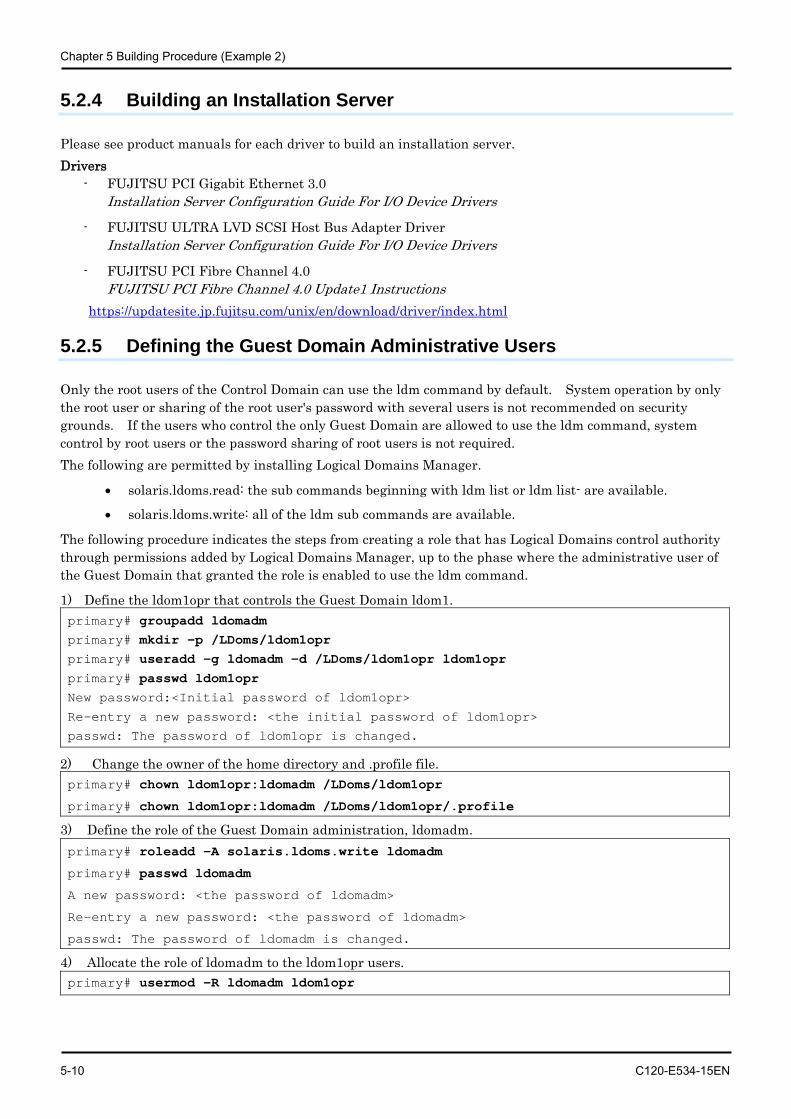
Chapter 5 Building Procedure (Example 2)
5-10 C120-E534-15EN
5.2.4 Building an Installation Server
Please see product manuals for each driver to build an installation server. Drivers
- FUJITSU PCI Gigabit Ethernet 3.0 Installation Server Configuration Guide For I/O Device Drivers
- FUJITSU ULTRA LVD SCSI Host Bus Adapter Driver Installation Server Configuration Guide For I/O Device Drivers
- FUJITSU PCI Fibre Channel 4.0 FUJITSU PCI Fibre Channel 4.0 Update1 Instructions
https://updatesite.jp.fujitsu.com/unix/en/download/driver/index.html
5.2.5 Defining the Guest Domain Administrative Users
Only the root users of the Control Domain can use the ldm command by default. System operation by only the root user or sharing of the root user's password with several users is not recommended on security grounds. If the users who control the only Guest Domain are allowed to use the ldm command, system control by root users or the password sharing of root users is not required. The following are permitted by installing Logical Domains Manager.
• solaris.ldoms.read: the sub commands beginning with ldm list or ldm list- are available.
• solaris.ldoms.write: all of the ldm sub commands are available.
The following procedure indicates the steps from creating a role that has Logical Domains control authority through permissions added by Logical Domains Manager, up to the phase where the administrative user of the Guest Domain that granted the role is enabled to use the ldm command.
1) Define the ldom1opr that controls the Guest Domain ldom1. primary# groupadd ldomadm primary# mkdir -p /LDoms/ldom1opr primary# useradd -g ldomadm -d /LDoms/ldom1opr ldom1opr primary# passwd ldom1opr New password:<Initial password of ldom1opr>
Re-entry a new password: <the initial password of ldom1opr>
passwd: The password of ldom1opr is changed.
2) Change the owner of the home directory and .profile file. primary# chown ldom1opr:ldomadm /LDoms/ldom1opr
primary# chown ldom1opr:ldomadm /LDoms/ldom1opr/.profile
3) Define the role of the Guest Domain administration, ldomadm. primary# roleadd -A solaris.ldoms.write ldomadm
primary# passwd ldomadm
A new password: <the password of ldomadm>
Re-entry a new password: <the password of ldomadm>
passwd: The password of ldomadm is changed.
4) Allocate the role of ldomadm to the ldom1opr users. primary# usermod -R ldomadm ldom1opr
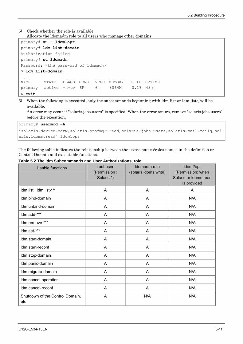
5.2 Building Procedure
C120-E534-15EN 5-11
5) Check whether the role is available. Allocate the ldomadm role to all users who manage other domains.
primary# su - ldom1opr primary# ldm list-domain Authorization failed primary# su ldomadm Password: <the password of ldomadm> $ ldm list-domain ... NAME STATE FLAGS CONS VCPU MEMORY UTIL UPTIME primary active -n-cv SP 64 8064M 0.1% 43m
$ exit
6) When the following is executed, only the subcommands beginning with ldm list or ldm list-, will be available. An error may occur if "solaris.jobs.users" is specified. When the error occurs, remove "solaris.jobs.users" before the execution.
primary# usermod -A
"solaris.device.cdrw,solaris.profmgr.read,solaris.jobs.users,solaris.mail.mailq,solaris.ldoms.read" ldom1opr
The following table indicates the relationship between the user's names/roles names in the definition or Control Domain and executable functions. Table 5.2 The ldm Subcommands and User Authorizations, role
Usable functions root user (Permission :
Solaris.*)
ldomadm role (solaris.ldoms.write)
ldom?opr (Permission: when
Solaris or ldoms.read is provided
ldm list , ldm list-*** A A A
ldm bind-domain A A N/A
ldm unbind-domain A A N/A
ldm add-*** A A N/A
ldm remove-*** A A N/A
ldm set-*** A A N/A
ldm start-domain A A N/A
ldm start-reconf A A N/A
ldm stop-domain A A N/A
ldm panic-domain A A N/A
ldm migrate-domain A A N/A
ldm cancel-operation A A N/A
ldm cancel-reconf A A N/A
Shutdown of the Control Domain, etc
A N/A N/A
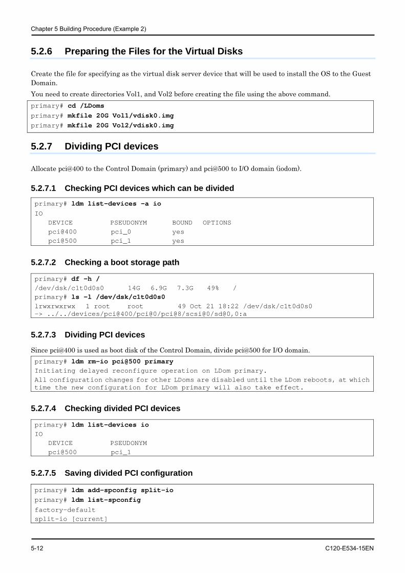
Chapter 5 Building Procedure (Example 2)
5-12 C120-E534-15EN
5.2.6 Preparing the Files for the Virtual Disks
Create the file for specifying as the virtual disk server device that will be used to install the OS to the Guest Domain. You need to create directories Vol1, and Vol2 before creating the file using the above command. primary# cd /LDoms primary# mkfile 20G Vol1/vdisk0.img primary# mkfile 20G Vol2/vdisk0.img
5.2.7 Dividing PCI devices
Allocate pci@400 to the Control Domain (primary) and pci@500 to I/O domain (iodom).
5.2.7.1 Checking PCI devices which can be divided
primary# ldm list-devices -a io IO DEVICE PSEUDONYM BOUND OPTIONS pci@400 pci_0 yes pci@500 pci_1 yes
5.2.7.2 Checking a boot storage path
primary# df -h / /dev/dsk/c1t0d0s0 14G 6.9G 7.3G 49% / primary# ls -l /dev/dsk/c1t0d0s0 lrwxrwxrwx 1 root root 49 Oct 21 18:22 /dev/dsk/c1t0d0s0 -> ../../devices/pci@400/pci@0/pci@8/scsi@0/sd@0,0:a
5.2.7.3 Dividing PCI devices
Since pci@400 is used as boot disk of the Control Domain, divide pci@500 for I/O domain. primary# ldm rm-io pci@500 primary Initiating delayed reconfigure operation on LDom primary. All configuration changes for other LDoms are disabled until the LDom reboots, at which time the new configuration for LDom primary will also take effect.
5.2.7.4 Checking divided PCI devices
primary# ldm list-devices io IO DEVICE PSEUDONYM pci@500 pci_1
5.2.7.5 Saving divided PCI configuration
primary# ldm add-spconfig split-io primary# ldm list-spconfig factory-default split-io [current]
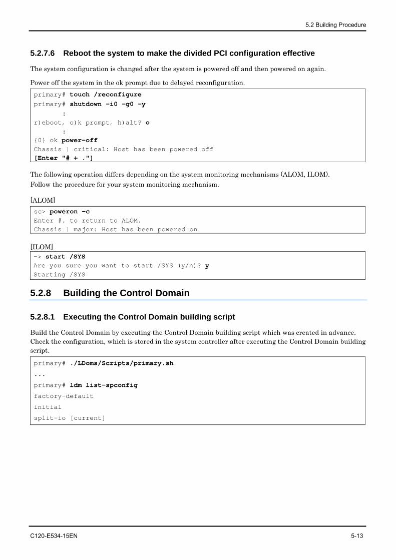
5.2 Building Procedure
C120-E534-15EN 5-13
5.2.7.6 Reboot the system to make the divided PCI configuration effective
The system configuration is changed after the system is powered off and then powered on again.
Power off the system in the ok prompt due to delayed reconfiguration. primary# touch /reconfigure primary# shutdown -i0 -g0 -y : r)eboot, o)k prompt, h)alt? o : {0} ok power-off Chassis | critical: Host has been powered off [Enter "# + ."]
The following operation differs depending on the system monitoring mechanisms (ALOM, ILOM). Follow the procedure for your system monitoring mechanism.
[ALOM] sc> poweron -c Enter #. to return to ALOM. Chassis | major: Host has been powered on
[ILOM] -> start /SYS Are you sure you want to start /SYS (y/n)? y Starting /SYS
5.2.8 Building the Control Domain
5.2.8.1 Executing the Control Domain building script
Build the Control Domain by executing the Control Domain building script which was created in advance. Check the configuration, which is stored in the system controller after executing the Control Domain building script.
primary# ./LDoms/Scripts/primary.sh
...
primary# ldm list-spconfig
factory-default
initial
split-io [current]
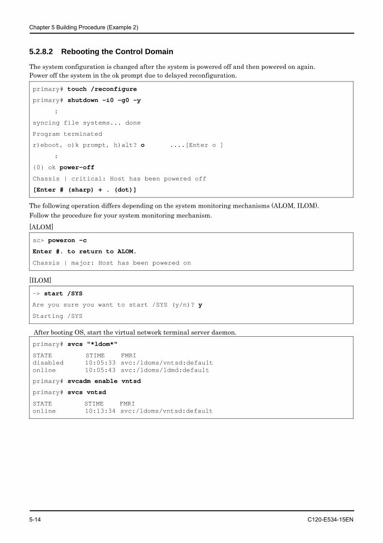
Chapter 5 Building Procedure (Example 2)
5-14 C120-E534-15EN
5.2.8.2 Rebooting the Control Domain
The system configuration is changed after the system is powered off and then powered on again. Power off the system in the ok prompt due to delayed reconfiguration.
primary# touch /reconfigure
primary# shutdown -i0 -g0 -y
:
syncing file systems... done
Program terminated
r)eboot, o)k prompt, h)alt? o ....[Enter o ]
:
{0} ok power-off
Chassis | critical: Host has been powered off
[Enter # (sharp) + . (dot)]
The following operation differs depending on the system monitoring mechanisms (ALOM, ILOM). Follow the procedure for your system monitoring mechanism.
[ALOM]
sc> poweron -c
Enter #. to return to ALOM.
Chassis | major: Host has been powered on
[ILOM]
-> start /SYS
Are you sure you want to start /SYS (y/n)? y
Starting /SYS
After booting OS, start the virtual network terminal server daemon. primary# svcs "*ldom*"
STATE STIME FMRI disabled 10:05:33 svc:/ldoms/vntsd:default online 10:05:43 svc:/ldoms/ldmd:default
primary# svcadm enable vntsd
primary# svcs vntsd
STATE STIME FMRI online 10:13:34 svc:/ldoms/vntsd:default
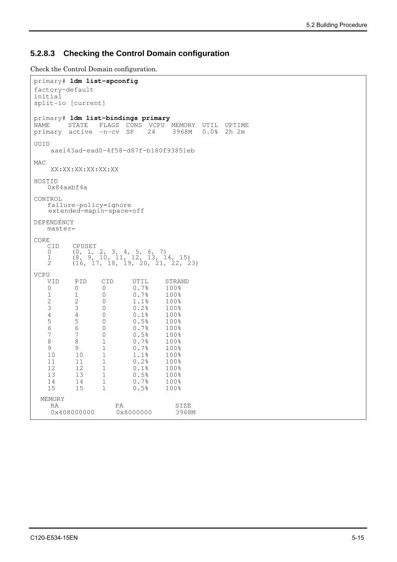
5.2 Building Procedure
C120-E534-15EN 5-15
5.2.8.3 Checking the Control Domain configuration
Check the Control Domain configuration. primary# ldm list-spconfig factory-default initial split-io [current] primary# ldm list-bindings primary NAME STATE FLAGS CONS VCPU MEMORY UTIL UPTIME primary active -n-cv SP 24 3968M 0.0% 2h 2m
UUID aae143ad-ead0-4f58-d87f-b180f93851eb
MAC XX:XX:XX:XX:XX:XX
HOSTID 0x84aabf4a
CONTROL failure-policy=ignore
extended-mapin-space=off
DEPENDENCY master=
CORE CID CPUSET 0 (0, 1, 2, 3, 4, 5, 6, 7) 1 (8, 9, 10, 11, 12, 13, 14, 15) 2 (16, 17, 18, 19, 20, 21, 22, 23)
VCPU VID PID CID UTIL STRAND 0 0 0 0.7% 100% 1 1 0 0.7% 100% 2 2 0 1.1% 100% 3 3 0 0.2% 100% 4 4 0 0.1% 100% 5 5 0 0.5% 100% 6 6 0 0.7% 100% 7 7 0 0.5% 100% 8 8 1 0.7% 100% 9 9 1 0.7% 100% 10 10 1 1.1% 100% 11 11 1 0.2% 100% 12 12 1 0.1% 100% 13 13 1 0.5% 100% 14 14 1 0.7% 100% 15 15 1 0.5% 100%
MEMORY RA PA SIZE 0x408000000 0x8000000 3968M
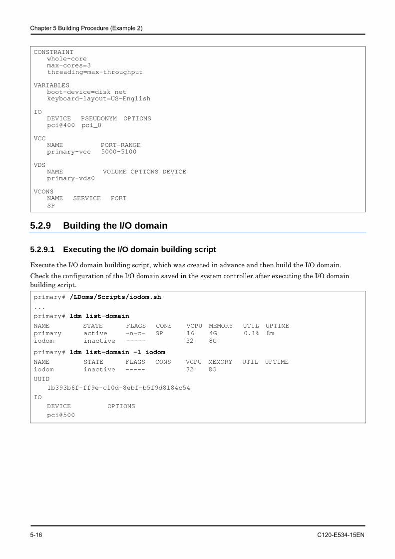
Chapter 5 Building Procedure (Example 2)
5-16 C120-E534-15EN
CONSTRAINT whole-core max-cores=3
threading=max-throughput VARIABLES boot-device=disk net keyboard-layout=US-English IO DEVICE PSEUDONYM OPTIONS pci@400 pci_0 VCC NAME PORT-RANGE primary-vcc 5000-5100 VDS NAME VOLUME OPTIONS DEVICE primary-vds0 VCONS NAME SERVICE PORT SP
5.2.9 Building the I/O domain
5.2.9.1 Executing the I/O domain building script
Execute the I/O domain building script, which was created in advance and then build the I/O domain. Check the configuration of the I/O domain saved in the system controller after executing the I/O domain building script. primary# /LDoms/Scripts/iodom.sh ... primary# ldm list-domain NAME STATE FLAGS CONS VCPU MEMORY UTIL UPTIME primary active -n-c- SP 16 4G 0.1% 8m iodom inactive ----- 32 8G
primary# ldm list-domain -l iodom NAME STATE FLAGS CONS VCPU MEMORY UTIL UPTIME iodom inactive ----- 32 8G
UUID 1b393b6f-ff9e-c10d-8ebf-b5f9d8184c54
IO DEVICE OPTIONS pci@500
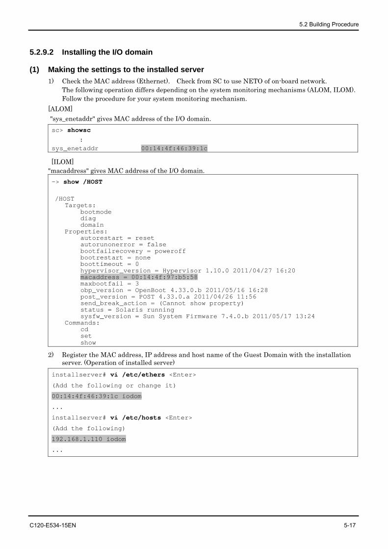
5.2 Building Procedure
C120-E534-15EN 5-17
5.2.9.2 Installing the I/O domain
(1) Making the settings to the installed server 1) Check the MAC address (Ethernet). Check from SC to use NETO of on-board network.
The following operation differs depending on the system monitoring mechanisms (ALOM, ILOM). Follow the procedure for your system monitoring mechanism.
[ALOM] "sys_enetaddr" gives MAC address of the I/O domain. sc> showsc
: sys_enetaddr 00:14:4f:46:39:1c
[ILOM] "macaddress" gives MAC address of the I/O domain. -> show /HOST
/HOST Targets:
bootmode diag domain
Properties: autorestart = reset autorunonerror = false bootfailrecovery = poweroff bootrestart = none boottimeout = 0 hypervisor_version = Hypervisor 1.10.0 2011/04/27 16:20 macaddress = 00:14:4f:97:b5:58 maxbootfail = 3 obp_version = OpenBoot 4.33.0.b 2011/05/16 16:28 post_version = POST 4.33.0.a 2011/04/26 11:56 send_break_action = (Cannot show property) status = Solaris running sysfw_version = Sun System Firmware 7.4.0.b 2011/05/17 13:24
Commands: cd set show
2) Register the MAC address, IP address and host name of the Guest Domain with the installation server. (Operation of installed server)
installserver# vi /etc/ethers <Enter>
(Add the following or change it)
00:14:4f:46:39:1c iodom
...
installserver# vi /etc/hosts <Enter>
(Add the following)
192.168.1.110 iodom
...
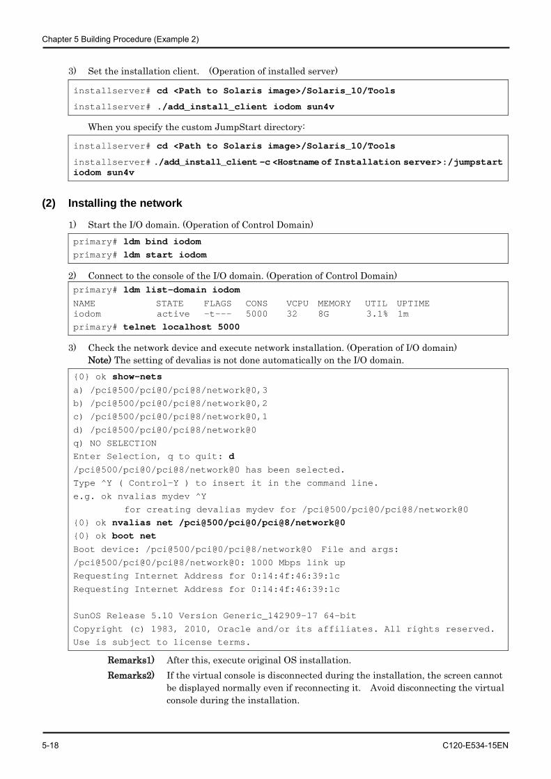
Chapter 5 Building Procedure (Example 2)
5-18 C120-E534-15EN
3) Set the installation client. (Operation of installed server)
installserver# cd <Path to Solaris image>/Solaris_10/Tools
installserver# ./add_install_client iodom sun4v
When you specify the custom JumpStart directory:
installserver# cd <Path to Solaris image>/Solaris_10/Tools
installserver# ./add_install_client -c <Hostname of Installation server>:/jumpstart iodom sun4v
(2) Installing the network
1) Start the I/O domain. (Operation of Control Domain) primary# ldm bind iodom primary# ldm start iodom
2) Connect to the console of the I/O domain. (Operation of Control Domain) primary# ldm list-domain iodom NAME STATE FLAGS CONS VCPU MEMORY UTIL UPTIME iodom active -t--- 5000 32 8G 3.1% 1m primary# telnet localhost 5000
3) Check the network device and execute network installation. (Operation of I/O domain) Note) The setting of devalias is not done automatically on the I/O domain.
{0} ok show-nets a) /pci@500/pci@0/pci@8/network@0,3
b) /pci@500/pci@0/pci@8/network@0,2
c) /pci@500/pci@0/pci@8/network@0,1
d) /pci@500/pci@0/pci@8/network@0
q) NO SELECTION Enter Selection, q to quit: d /pci@500/pci@0/pci@8/network@0 has been selected.
Type ^Y ( Control-Y ) to insert it in the command line.
e.g. ok nvalias mydev ^Y
for creating devalias mydev for /pci@500/pci@0/pci@8/network@0 {0} ok nvalias net /pci@500/pci@0/pci@8/network@0 {0} ok boot net Boot device: /pci@500/pci@0/pci@8/network@0 File and args:
/pci@500/pci@0/pci@8/network@0: 1000 Mbps link up
Requesting Internet Address for 0:14:4f:46:39:1c
Requesting Internet Address for 0:14:4f:46:39:1c
SunOS Release 5.10 Version Generic_142909-17 64-bit
Copyright (c) 1983, 2010, Oracle and/or its affiliates. All rights reserved.
Use is subject to license terms.
Remarks1) After this, execute original OS installation. Remarks2) If the virtual console is disconnected during the installation, the screen cannot
be displayed normally even if reconnecting it. Avoid disconnecting the virtual console during the installation.
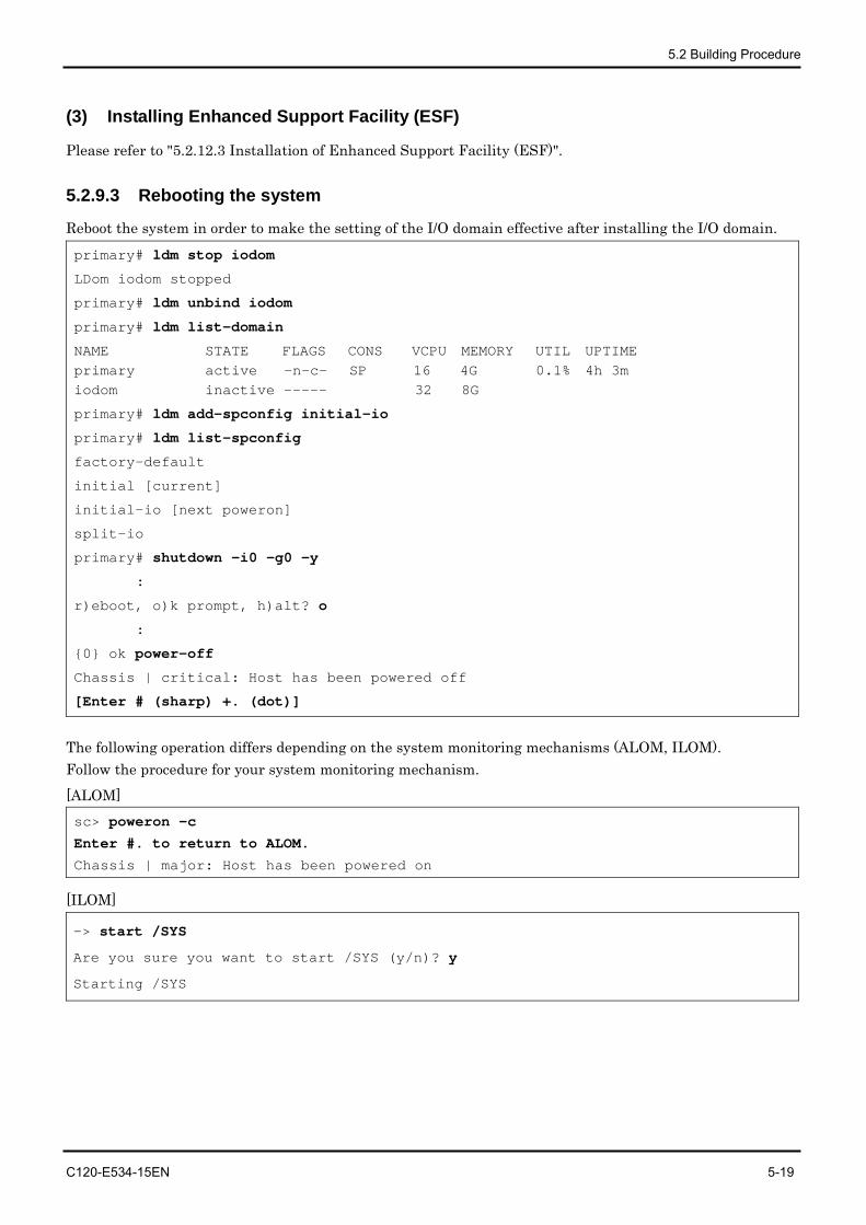
5.2 Building Procedure
C120-E534-15EN 5-19
(3) Installing Enhanced Support Facility (ESF)
Please refer to "5.2.12.3 Installation of Enhanced Support Facility (ESF)".
5.2.9.3 Rebooting the system
Reboot the system in order to make the setting of the I/O domain effective after installing the I/O domain. primary# ldm stop iodom
LDom iodom stopped
primary# ldm unbind iodom
primary# ldm list-domain
NAME STATE FLAGS CONS VCPU MEMORY UTIL UPTIME primary active -n-c- SP 16 4G 0.1% 4h 3m iodom inactive ----- 32 8G
primary# ldm add-spconfig initial-io
primary# ldm list-spconfig
factory-default
initial [current]
initial-io [next poweron]
split-io
primary# shutdown -i0 -g0 -y
:
r)eboot, o)k prompt, h)alt? o
:
{0} ok power-off
Chassis | critical: Host has been powered off
[Enter # (sharp) +. (dot)]
The following operation differs depending on the system monitoring mechanisms (ALOM, ILOM). Follow the procedure for your system monitoring mechanism. [ALOM] sc> poweron -c
Enter #. to return to ALOM.
Chassis | major: Host has been powered on
[ILOM]
-> start /SYS
Are you sure you want to start /SYS (y/n)? y
Starting /SYS
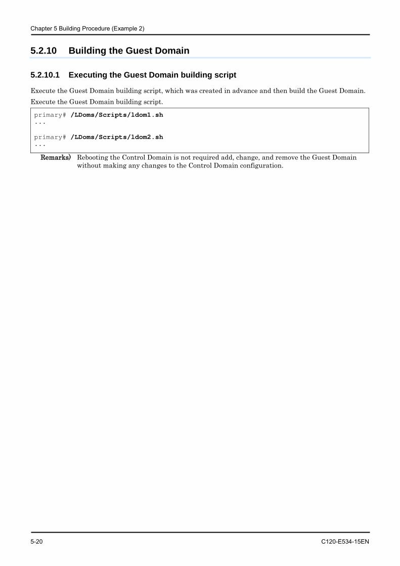
Chapter 5 Building Procedure (Example 2)
5-20 C120-E534-15EN
5.2.10 Building the Guest Domain
5.2.10.1 Executing the Guest Domain building script
Execute the Guest Domain building script, which was created in advance and then build the Guest Domain. Execute the Guest Domain building script.
primary# /LDoms/Scripts/ldom1.sh ... primary# /LDoms/Scripts/ldom2.sh ...
Remarks) Rebooting the Control Domain is not required add, change, and remove the Guest Domain without making any changes to the Control Domain configuration.
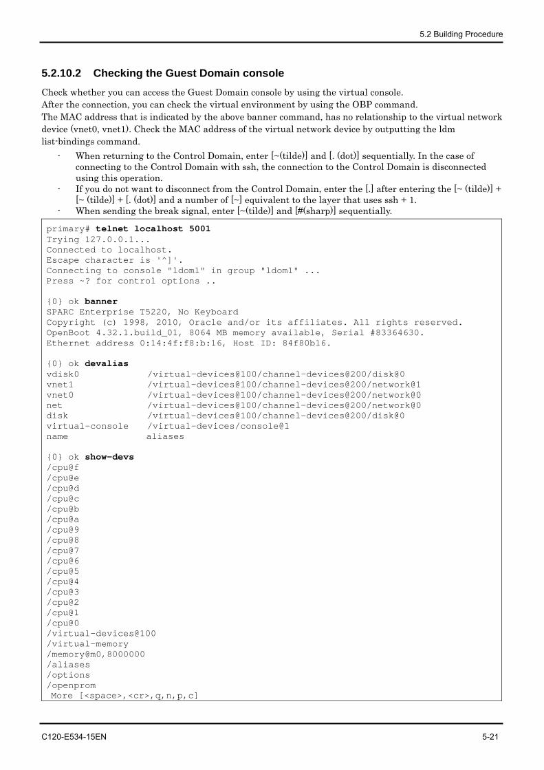
5.2 Building Procedure
C120-E534-15EN 5-21
5.2.10.2 Checking the Guest Domain console Check whether you can access the Guest Domain console by using the virtual console. After the connection, you can check the virtual environment by using the OBP command. The MAC address that is indicated by the above banner command, has no relationship to the virtual network device (vnet0, vnet1). Check the MAC address of the virtual network device by outputting the ldm list-bindings command.
- When returning to the Control Domain, enter [~(tilde)] and [. (dot)] sequentially. In the case of connecting to the Control Domain with ssh, the connection to the Control Domain is disconnected using this operation.
- If you do not want to disconnect from the Control Domain, enter the [.] after entering the [~ (tilde)] + [~ (tilde)] + [. (dot)] and a number of [~] equivalent to the layer that uses ssh + 1.
- When sending the break signal, enter [~(tilde)] and [#(sharp)] sequentially.
primary# telnet localhost 5001 Trying 127.0.0.1... Connected to localhost. Escape character is '^]'. Connecting to console "ldom1" in group "ldom1" ... Press ~? for control options .. {0} ok banner SPARC Enterprise T5220, No Keyboard Copyright (c) 1998, 2010, Oracle and/or its affiliates. All rights reserved. OpenBoot 4.32.1.build_01, 8064 MB memory available, Serial #83364630. Ethernet address 0:14:4f:f8:b:16, Host ID: 84f80b16. {0} ok devalias vdisk0 /virtual-devices@100/channel-devices@200/disk@0 vnet1 /virtual-devices@100/channel-devices@200/network@1 vnet0 /virtual-devices@100/channel-devices@200/network@0 net /virtual-devices@100/channel-devices@200/network@0 disk /virtual-devices@100/channel-devices@200/disk@0 virtual-console /virtual-devices/console@1 name aliases {0} ok show-devs /cpu@f /cpu@e /cpu@d /cpu@c /cpu@b /cpu@a /cpu@9 /cpu@8 /cpu@7 /cpu@6 /cpu@5 /cpu@4 /cpu@3 /cpu@2 /cpu@1 /cpu@0 /virtual-devices@100 /virtual-memory /memory@m0,8000000 /aliases /options /openprom More [<space>,<cr>,q,n,p,c]
Chapter 5 Building Procedure (Example 2)
5-22 C120-E534-15EN
5.2.11 Retaining the Logical Domains Configuration Information
Logical Domains Manager 1.2 Patch 142840-04 or newer needs to be applied to get the configuration information (For Logical Domains 1.2). After applying 142840-04 or newer, please get the configuration information. The hypervisor reads the Logical Domains configuration stored in EEPROM at the time of power activation. The Logical Domains configuration may be lost as a result of a failure of hardware which includes EEPROM, such as a motherboard. The Logical Domains Manager starts the Guest Domain by referring to the Logical Domains configuration which has been stored on the disk (/var/opt/SUNWldm/). If this disk cannot be accessed, the Guest Domain will not start the Guest Domain. The following corrective actions are recommended for these conditions.
• Save of the building script. Save the building script in a certain location (/LDoms/Scripts/ in this document) so that the latest Control Domain building script (primary.sh in this document) or Guest Domain building script (ldom?.sh in this document) can be executed as required, and so that the Logical Domains environment can be rebuilt.
• Collection/Save of the Control/Guest Domain configuration information. The outputs of ldm list-constraints -x when used for the input of ldm init-system -r -i [file-name], can rebuild the collected Control Domain. Also, the outputs of ldm list-constraints -x [domain-name] when used for the input of ldm add-domain -i [file-name], can rebuild the collected Guest Domain. Collect the configuration information of the Control/Guest Domain whenever the configuration is changed and save it in a certain location (/LDoms/Domains/ in this document).
• Getting and saving of the configuration information saved automatically. If you change the configuration information on Logical Domains 1.2, the change is reflected also to the auto-saved configuration information. You can use "ldm list-spconfig -r" to check the list of the configuration information saved automatically. Please save the auto-saved configuration information on the disk (/var/opt/SUNWldm/autosave-[autosave-name(*)]/) into the same location (/LDoms/Domains/ in this chapter) as the configuration information saved in "Collection/Save of the Guest Domain configuration information". *autosave-name: The name of the auto-saved configuration information in the Control Domain
Be sure to login as root user to execute the following procedure. The following is an example of a method for saving. In this section, the auto-saved configuration information "webDB-config" is saved as "autosave-webDB-config.<date_time>.tar". 1) Check the name of the auto-saved configuration information. primary# ldm list-spconfig -r webDB-config
2) Save the auto-saved directory. primary# cd /var/opt/SUNWldm primary# tar -cvf /LDoms/Domains/autosave-webDB-config.`date +%y%m%d%H%M%S`.tar autosave-webDB-config
- Save of the information to external media. Copy the information in the CD-R, DVD-R, tapes or file servers to be prepared in case they are lost from the disk.
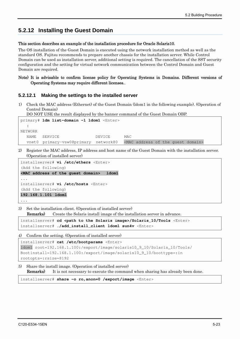
5.2 Building Procedure
C120-E534-15EN 5-23
5.2.12 Installing the Guest Domain
This section describes an example of the installation procedure for Oracle Solaris10. The OS installation of the Guest Domain is executed using the network installation method as well as the standard OS. Fujitsu recommends to prepare another chassis for the installation server. While Control Domain can be used as installation server, additional setting is required. The cancellation of the SST security configuration and the setting for virtual network communication between the Control Domain and Guest Domain are required.
Note) It is advisable to confirm license policy for Operating Systems in Domains. Different versions of Operating Systems may require different licenses..
5.2.12.1 Making the settings to the installed server
1) Check the MAC address (Ethernet) of the Guest Domain (ldom1 in the following example). (Operation of Control Domain) DO NOT USE the result displayed by the banner command of the Guest Domain OBP.
primary# ldm list-domain -l ldom1 <Enter> : NETWORK NAME SERVICE DEVICE MAC vnet0 primary-vsw0@primary network@0 <MAC address of the guest domain>
2) Register the MAC address, IP address and host name of the Guest Domain with the installation server. (Operation of installed server)
installserver# vi /etc/ethers <Enter> (Add the following) <MAC address of the guest domain> ldom1 ... installserver# vi /etc/hosts <Enter> (Add the following) 192.168.1.101 ldom1 ...
3) Set the installation client. (Operation of installed server) Remarks) Create the Solaris install image of the installation server in advance.
installserver# cd <path to the Solaris image>/Solaris_10/Tools <Enter> installserver# ./add_install_client ldom1 sun4v <Enter>
4) Confirm the setting. (Operation of installed server) installserver# cat /etc/bootparams <Enter> ldom1 root=192.168.1.100:/export/image/solaris10_9_10/Solaris_10/Tools/ Bootinstall=192.168.1.100:/export/image/solaris10_9_10/boottype=:in rootopts=:rsize=8192
5) Share the install image. (Operation of installed server) Remarks) It is not necessary to execute the command when sharing has already been done.
installserver# share -o ro,anon=0 /export/image <Enter>
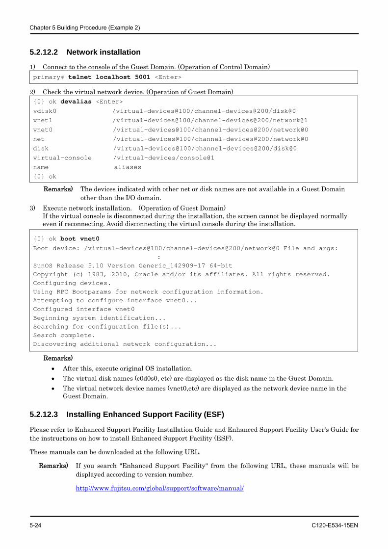
Chapter 5 Building Procedure (Example 2)
5-24 C120-E534-15EN
5.2.12.2 Network installation
1) Connect to the console of the Guest Domain. (Operation of Control Domain) primary# telnet localhost 5001 <Enter>
2) Check the virtual network device. (Operation of Guest Domain) {0} ok devalias <Enter> vdisk0 /virtual-devices@100/channel-devices@200/disk@0
vnet1 /virtual-devices@100/channel-devices@200/network@1
vnet0 /virtual-devices@100/channel-devices@200/network@0
net /virtual-devices@100/channel-devices@200/network@0
disk /virtual-devices@100/channel-devices@200/disk@0
virtual-console /virtual-devices/console@1
name aliases
{0} ok
Remarks) The devices indicated with other net or disk names are not available in a Guest Domain other than the I/O domain.
3) Execute network installation. (Operation of Guest Domain) If the virtual console is disconnected during the installation, the screen cannot be displayed normally even if reconnecting. Avoid disconnecting the virtual console during the installation.
{0} ok boot vnet0 Boot device: /virtual-devices@100/channel-devices@200/network@0 File and args:
: SunOS Release 5.10 Version Generic_142909-17 64-bit Copyright (c) 1983, 2010, Oracle and/or its affiliates. All rights reserved. Configuring devices. Using RPC Bootparams for network configuration information. Attempting to configure interface vnet0... Configured interface vnet0 Beginning system identification... Searching for configuration file(s)... Search complete. Discovering additional network configuration...
Remarks) • After this, execute original OS installation. • The virtual disk names (c0d0s0, etc) are displayed as the disk name in the Guest Domain. • The virtual network device names (vnet0,etc) are displayed as the network device name in the
Guest Domain.
5.2.12.3 Installing Enhanced Support Facility (ESF)
Please refer to Enhanced Support Facility Installation Guide and Enhanced Support Facility User's Guide for the instructions on how to install Enhanced Support Facility (ESF).
These manuals can be downloaded at the following URL.
Remarks) If you search "Enhanced Support Facility" from the following URL, these manuals will be displayed according to version number.
http://www.fujitsu.com/global/support/software/manual/
5.2 Building Procedure
C120-E534-15EN 5-25
5.2.13 Saving the Logical Domains setting
After determining the configuration of your operation, please save the configuration and make a backup of the Logical Domains setting again. Regarding the backup of the Logical Domains configuration, please refer to "Appendix A Instructions for Backup/Restoration of UFS file system".
primary# ldm add-spconfig operation
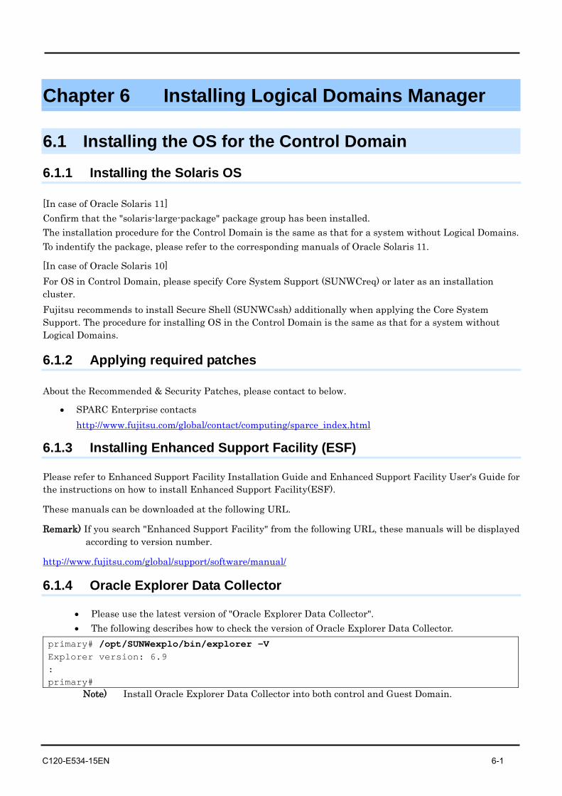
C120-E534-15EN 6-1
Chapter 6 Installing Logical Domains Manager
6.1 Installing the OS for the Control Domain
6.1.1 Installing the Solaris OS
[In case of Oracle Solaris 11] Confirm that the "solaris-large-package" package group has been installed. The installation procedure for the Control Domain is the same as that for a system without Logical Domains. To indentify the package, please refer to the corresponding manuals of Oracle Solaris 11.
[In case of Oracle Solaris 10] For OS in Control Domain, please specify Core System Support (SUNWCreq) or later as an installation cluster. Fujitsu recommends to install Secure Shell (SUNWCssh) additionally when applying the Core System Support. The procedure for installing OS in the Control Domain is the same as that for a system without Logical Domains.
6.1.2 Applying required patches
About the Recommended & Security Patches, please contact to below.
• SPARC Enterprise contacts http://www.fujitsu.com/global/contact/computing/sparce_index.html
6.1.3 Installing Enhanced Support Facility (ESF)
Please refer to Enhanced Support Facility Installation Guide and Enhanced Support Facility User's Guide for the instructions on how to install Enhanced Support Facility(ESF).
These manuals can be downloaded at the following URL.
Remark) If you search "Enhanced Support Facility" from the following URL, these manuals will be displayed according to version number.
http://www.fujitsu.com/global/support/software/manual/
6.1.4 Oracle Explorer Data Collector
• Please use the latest version of "Oracle Explorer Data Collector". • The following describes how to check the version of Oracle Explorer Data Collector.
primary# /opt/SUNWexplo/bin/explorer -V Explorer version: 6.9 : primary#
Note) Install Oracle Explorer Data Collector into both control and Guest Domain.
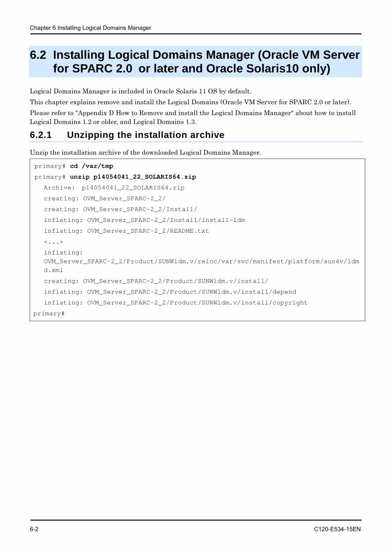
Chapter 6 Installing Logical Domains Manager
6-2 C120-E534-15EN
6.2 Installing Logical Domains Manager (Oracle VM Server for SPARC 2.0 or later and Oracle Solaris10 only)
Logical Domains Manager is included in Oracle Solaris 11 OS by default. This chapter explains remove and install the Logical Domains (Oracle VM Server for SPARC 2.0 or later). Please refer to "Appendix D How to Remove and install the Logical Domains Manager" about how to install Logical Domains 1.2 or older, and Logical Domains 1.3.
6.2.1 Unzipping the installation archive
Unzip the installation archive of the downloaded Logical Domains Manager.
primary# cd /var/tmp
primary# unzip p14054041_22_SOLARIS64.zip
Archive: p14054041_22_SOLARIS64.zip
creating: OVM_Server_SPARC-2_2/
creating: OVM_Server_SPARC-2_2/Install/
inflating: OVM_Server_SPARC-2_2/Install/install-ldm
inflating: OVM_Server_SPARC-2_2/README.txt
<...>
inflating: OVM_Server_SPARC-2_2/Product/SUNWldm.v/reloc/var/svc/manifest/platform/sun4v/ldmd.xml
creating: OVM_Server_SPARC-2_2/Product/SUNWldm.v/install/
inflating: OVM_Server_SPARC-2_2/Product/SUNWldm.v/install/depend
inflating: OVM_Server_SPARC-2_2/Product/SUNWldm.v/install/copyright
primary#
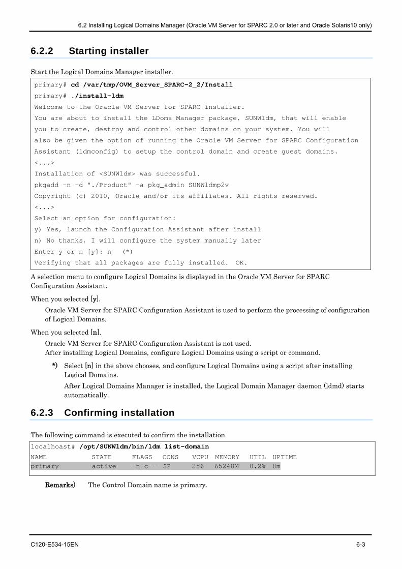
6.2 Installing Logical Domains Manager (Oracle VM Server for SPARC 2.0 or later and Oracle Solaris10 only)
C120-E534-15EN 6-3
6.2.2 Starting installer
Start the Logical Domains Manager installer.
primary# cd /var/tmp/OVM_Server_SPARC-2_2/Install
primary# ./install-ldm
Welcome to the Oracle VM Server for SPARC installer.
You are about to install the LDoms Manager package, SUNWldm, that will enable
you to create, destroy and control other domains on your system. You will
also be given the option of running the Oracle VM Server for SPARC Configuration
Assistant (ldmconfig) to setup the control domain and create guest domains.
<...>
Installation of <SUNWldm> was successful.
pkgadd -n -d "./Product" -a pkg_admin SUNWldmp2v
Copyright (c) 2010, Oracle and/or its affiliates. All rights reserved.
<...>
Select an option for configuration:
y) Yes, launch the Configuration Assistant after install
n) No thanks, I will configure the system manually later
Enter y or n [y]: n (*)
Verifying that all packages are fully installed. OK.
A selection menu to configure Logical Domains is displayed in the Oracle VM Server for SPARC Configuration Assistant.
When you selected [y]. Oracle VM Server for SPARC Configuration Assistant is used to perform the processing of configuration of Logical Domains.
When you selected [n]. Oracle VM Server for SPARC Configuration Assistant is not used. After installing Logical Domains, configure Logical Domains using a script or command.
*) Select [n] in the above chooses, and configure Logical Domains using a script after installing Logical Domains. After Logical Domains Manager is installed, the Logical Domain Manager daemon (ldmd) starts automatically.
6.2.3 Confirming installation
The following command is executed to confirm the installation. localhoast# /opt/SUNWldm/bin/ldm list-domain
NAME STATE FLAGS CONS VCPU MEMORY UTIL UPTIME primary active -n-c-- SP 256 65248M 0.2% 8m
Remarks) The Control Domain name is primary.
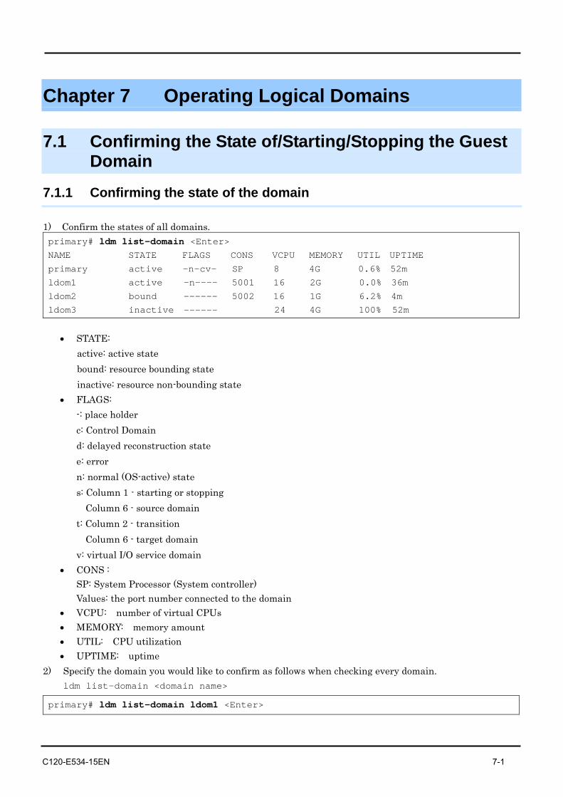
C120-E534-15EN 7-1
Chapter 7 Operating Logical Domains
7.1 Confirming the State of/Starting/Stopping the Guest Domain
7.1.1 Confirming the state of the domain
1) Confirm the states of all domains. primary# ldm list-domain <Enter> NAME STATE FLAGS CONS VCPU MEMORY UTIL UPTIME
primary active -n-cv- SP 8 4G 0.6% 52m
ldom1 active -n---- 5001 16 2G 0.0% 36m
ldom2 bound ------ 5002 16 1G 6.2% 4m
ldom3 inactive ------ 24 4G 100% 52m
• STATE:
active: active state bound: resource bounding state inactive: resource non-bounding state
• FLAGS: -: place holder c: Control Domain d: delayed reconstruction state e: error n: normal (OS-active) state s: Column 1 - starting or stopping
Column 6 - source domain t: Column 2 - transition
Column 6 - target domain v: virtual I/O service domain
• CONS : SP: System Processor (System controller) Values: the port number connected to the domain
• VCPU: number of virtual CPUs • MEMORY: memory amount • UTIL: CPU utilization • UPTIME: uptime
2) Specify the domain you would like to confirm as follows when checking every domain. ldm list-domain <domain name>
primary# ldm list-domain ldom1 <Enter>
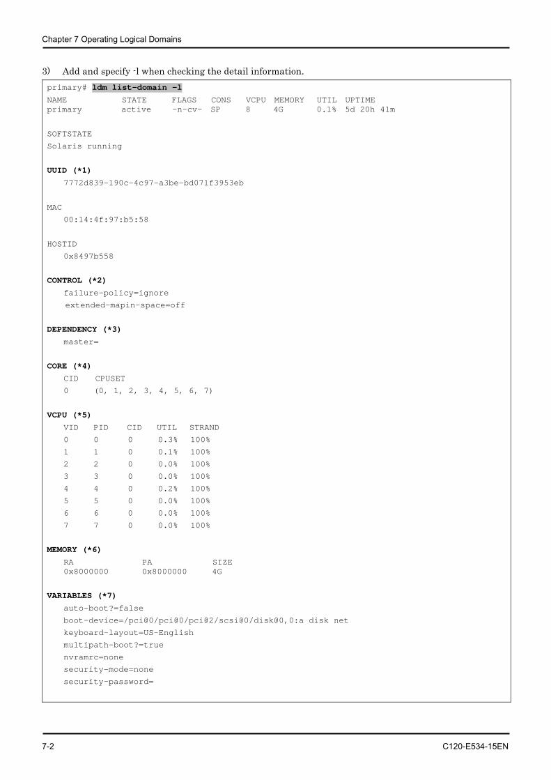
Chapter 7 Operating Logical Domains
7-2 C120-E534-15EN
3) Add and specify -l when checking the detail information. primary# ldm list-domain -l
NAME STATE FLAGS CONS VCPU MEMORY UTIL UPTIME primary active -n-cv- SP 8 4G 0.1% 5d 20h 41m
SOFTSTATE
Solaris running
UUID (*1)
7772d839-190c-4c97-a3be-bd071f3953eb
MAC
00:14:4f:97:b5:58
HOSTID
0x8497b558
CONTROL (*2)
failure-policy=ignore
extended-mapin-space=off
DEPENDENCY (*3)
master=
CORE (*4)
CID CPUSET
0 (0, 1, 2, 3, 4, 5, 6, 7)
VCPU (*5)
VID PID CID UTIL STRAND
0 0 0 0.3% 100%
1 1 0 0.1% 100%
2 2 0 0.0% 100%
3 3 0 0.0% 100%
4 4 0 0.2% 100%
5 5 0 0.0% 100%
6 6 0 0.0% 100%
7 7 0 0.0% 100%
MEMORY (*6)
RA PA SIZE 0x8000000 0x8000000 4G
VARIABLES (*7)
auto-boot?=false
boot-device=/pci@0/pci@0/pci@2/scsi@0/disk@0,0:a disk net
keyboard-layout=US-English
multipath-boot?=true
nvramrc=none
security-mode=none
security-password=
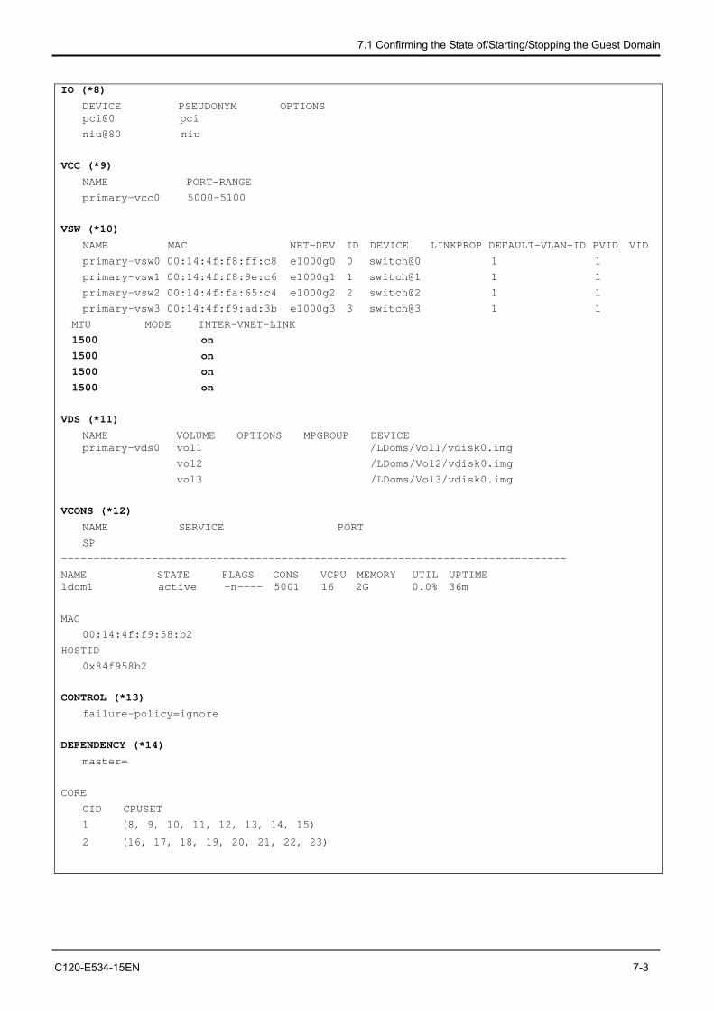
7.1 Confirming the State of/Starting/Stopping the Guest Domain
C120-E534-15EN 7-3
IO (*8)
DEVICE PSEUDONYM OPTIONS pci@0 pci
niu@80 niu
VCC (*9)
NAME PORT-RANGE
primary-vcc0 5000-5100
VSW (*10)
NAME MAC NET-DEV ID DEVICE LINKPROP DEFAULT-VLAN-ID PVID VID
primary-vsw0 00:14:4f:f8:ff:c8 e1000g0 0 switch@0 1 1
primary-vsw1 00:14:4f:f8:9e:c6 e1000g1 1 switch@1 1 1
primary-vsw2 00:14:4f:fa:65:c4 e1000g2 2 switch@2 1 1
primary-vsw3 00:14:4f:f9:ad:3b e1000g3 3 switch@3 1 1
MTU MODE INTER-VNET-LINK
1500 on 1500 on 1500 on 1500 on VDS (*11)
NAME VOLUME OPTIONS MPGROUP DEVICE primary-vds0 vol1 /LDoms/Vol1/vdisk0.img
vol2 /LDoms/Vol2/vdisk0.img
vol3 /LDoms/Vol3/vdisk0.img
VCONS (*12)
NAME SERVICE PORT
SP
------------------------------------------------------------------------------
NAME STATE FLAGS CONS VCPU MEMORY UTIL UPTIME ldom1 active -n---- 5001 16 2G 0.0% 36m
MAC
00:14:4f:f9:58:b2
HOSTID
0x84f958b2
CONTROL (*13)
failure-policy=ignore
DEPENDENCY (*14)
master=
CORE
CID CPUSET
1 (8, 9, 10, 11, 12, 13, 14, 15)
2 (16, 17, 18, 19, 20, 21, 22, 23)
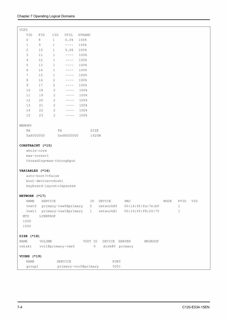
Chapter 7 Operating Logical Domains
7-4 C120-E534-15EN
VCPU
VID PID CID UTIL STRAND
0 8 1 0.5% 100%
1 9 1 ---- 100%
2 10 1 0.6% 100%
3 11 1 ---- 100%
4 12 1 ---- 100%
5 13 1 ---- 100%
6 14 1 ---- 100%
7 15 1 ---- 100%
8 16 2 ---- 100%
9 17 2 ---- 100%
10 18 2 ---- 100%
11 19 2 ---- 100%
12 20 2 ---- 100%
13 21 2 ---- 100%
14 22 2 ---- 100%
15 23 2 ---- 100%
MEMORY
RA PA SIZE
0x8000000 0x48000000 1920M
CONSTRAINT (*15)
whole-core
max-cores=1
threading=max-throughput
VARIABLES (*16)
auto-boot?=false
boot-device=vdisk1
keyboard-layout=Japanese
NETWORK (*17)
NAME SERVICE ID DEVICE MAC MODE PVID VID
vnet0 primary-vsw0@primary 0 network@0 00:14:4f:fa:7e:b0 1
vnet1 primary-vsw1@primary 1 network@1 00:14:4f:f8:24:7f 1
MTU LINKPROP
1500
1500
DISK (*18)
NAME VOLUME TOUT ID DEVICE SERVER MPGROUP
vdisk1 vol1@primary-vds0 0 disk@0 primary
VCONS (*19)
NAME SERVICE PORT
group1 primary-vcc0@primary 5001
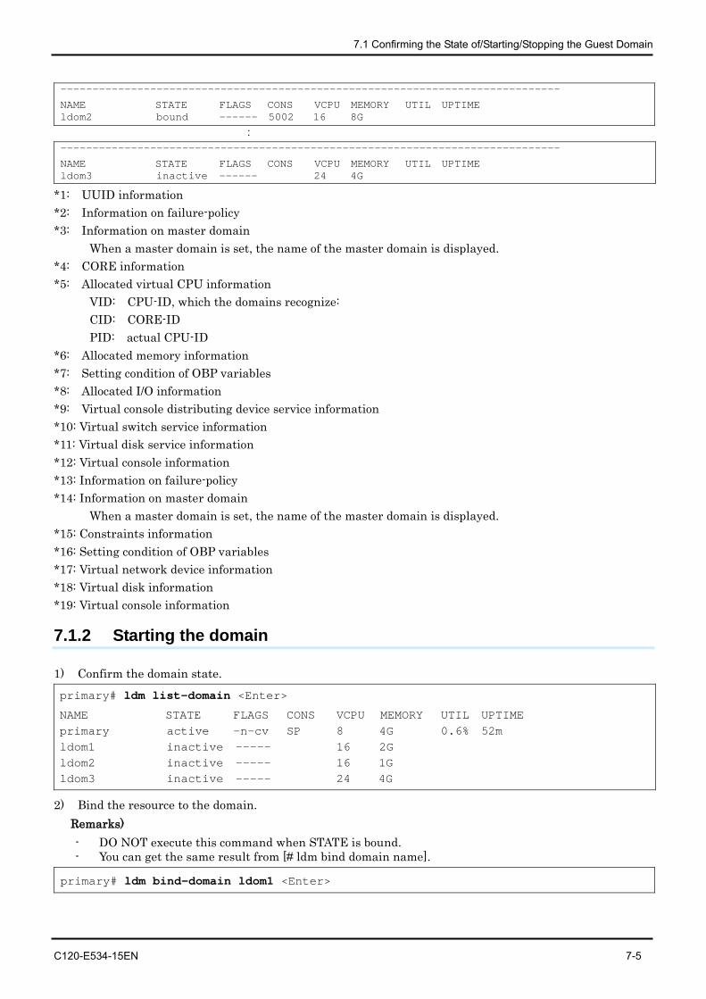
7.1 Confirming the State of/Starting/Stopping the Guest Domain
C120-E534-15EN 7-5
------------------------------------------------------------------------------
NAME STATE FLAGS CONS VCPU MEMORY UTIL UPTIME ldom2 bound ------ 5002 16 8G
: ------------------------------------------------------------------------------
NAME STATE FLAGS CONS VCPU MEMORY UTIL UPTIME ldom3 inactive ------ 24 4G
*1: UUID information *2: Information on failure-policy *3: Information on master domain When a master domain is set, the name of the master domain is displayed. *4: CORE information *5: Allocated virtual CPU information VID: CPU-ID, which the domains recognize: CID: CORE-ID PID: actual CPU-ID *6: Allocated memory information *7: Setting condition of OBP variables *8: Allocated I/O information *9: Virtual console distributing device service information *10: Virtual switch service information *11: Virtual disk service information *12: Virtual console information *13: Information on failure-policy *14: Information on master domain When a master domain is set, the name of the master domain is displayed. *15: Constraints information *16: Setting condition of OBP variables *17: Virtual network device information *18: Virtual disk information *19: Virtual console information
7.1.2 Starting the domain
1) Confirm the domain state. primary# ldm list-domain <Enter>
NAME STATE FLAGS CONS VCPU MEMORY UTIL UPTIME primary active -n-cv SP 8 4G 0.6% 52m ldom1 inactive ----- 16 2G ldom2 inactive ----- 16 1G ldom3 inactive ----- 24 4G
2) Bind the resource to the domain. Remarks) - DO NOT execute this command when STATE is bound. - You can get the same result from [# ldm bind domain name].
primary# ldm bind-domain ldom1 <Enter>
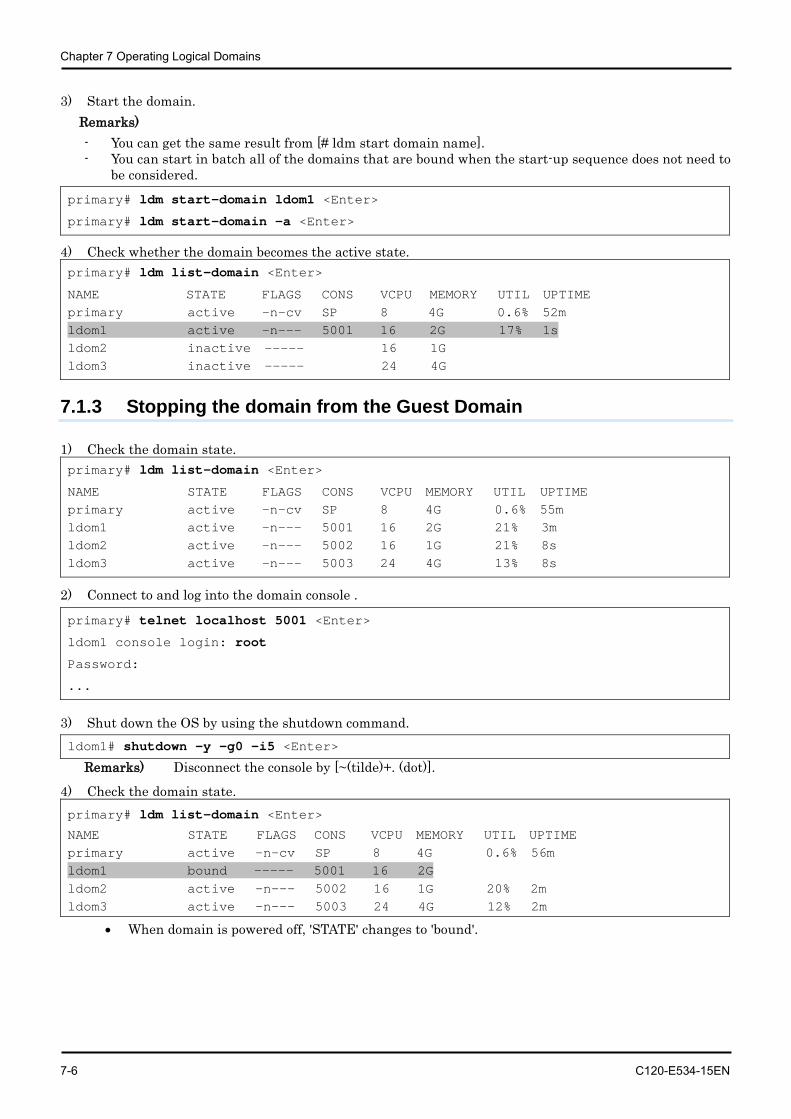
Chapter 7 Operating Logical Domains
7-6 C120-E534-15EN
3) Start the domain. Remarks) - You can get the same result from [# ldm start domain name]. - You can start in batch all of the domains that are bound when the start-up sequence does not need to
be considered.
primary# ldm start-domain ldom1 <Enter>
primary# ldm start-domain -a <Enter>
4) Check whether the domain becomes the active state. primary# ldm list-domain <Enter>
NAME STATE FLAGS CONS VCPU MEMORY UTIL UPTIME primary active -n-cv SP 8 4G 0.6% 52m ldom1 active -n--- 5001 16 2G 17% 1s ldom2 inactive ----- 16 1G ldom3 inactive ----- 24 4G
7.1.3 Stopping the domain from the Guest Domain
1) Check the domain state. primary# ldm list-domain <Enter>
NAME STATE FLAGS CONS VCPU MEMORY UTIL UPTIME primary active -n-cv SP 8 4G 0.6% 55m ldom1 active -n--- 5001 16 2G 21% 3m ldom2 active -n--- 5002 16 1G 21% 8s ldom3 active -n--- 5003 24 4G 13% 8s
2) Connect to and log into the domain console .
primary# telnet localhost 5001 <Enter>
ldom1 console login: root
Password:
...
3) Shut down the OS by using the shutdown command. ldom1# shutdown -y -g0 -i5 <Enter>
Remarks) Disconnect the console by [~(tilde)+. (dot)].
4) Check the domain state. primary# ldm list-domain <Enter>
NAME STATE FLAGS CONS VCPU MEMORY UTIL UPTIME primary active -n-cv SP 8 4G 0.6% 56m ldom1 bound ----- 5001 16 2G ldom2 active -n--- 5002 16 1G 20% 2m ldom3 active -n--- 5003 24 4G 12% 2m
• When domain is powered off, 'STATE' changes to 'bound'.
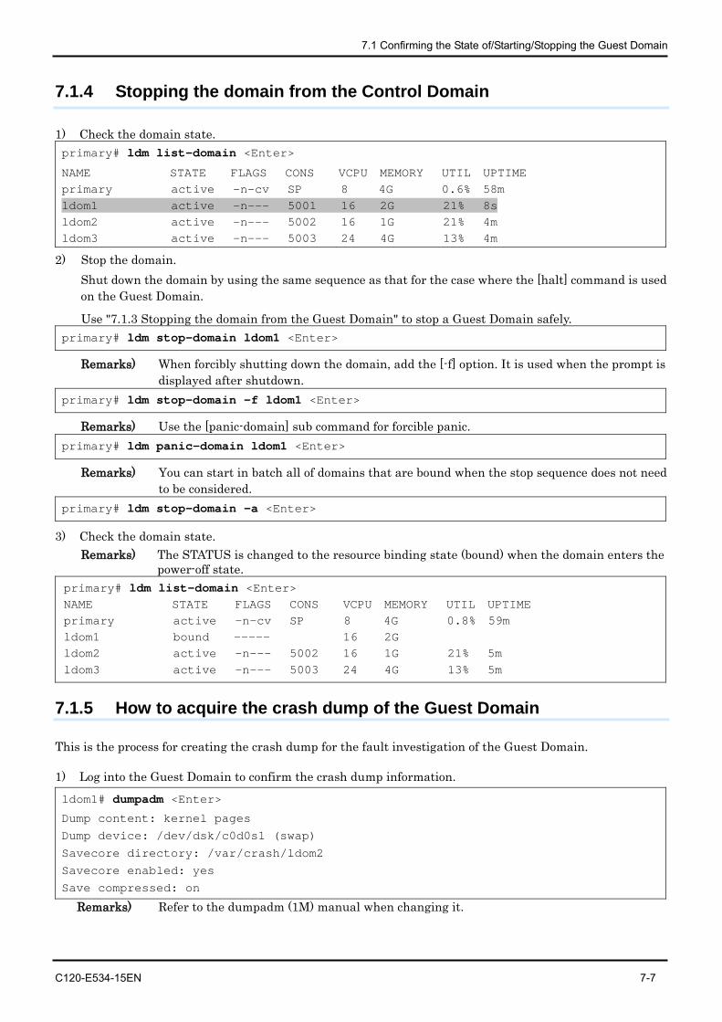
7.1 Confirming the State of/Starting/Stopping the Guest Domain
C120-E534-15EN 7-7
7.1.4 Stopping the domain from the Control Domain
1) Check the domain state. primary# ldm list-domain <Enter>
NAME STATE FLAGS CONS VCPU MEMORY UTIL UPTIME primary active -n-cv SP 8 4G 0.6% 58m ldom1 active -n--- 5001 16 2G 21% 8s ldom2 active -n--- 5002 16 1G 21% 4m ldom3 active -n--- 5003 24 4G 13% 4m
2) Stop the domain. Shut down the domain by using the same sequence as that for the case where the [halt] command is used on the Guest Domain.
Use "7.1.3 Stopping the domain from the Guest Domain" to stop a Guest Domain safely. primary# ldm stop-domain ldom1 <Enter>
Remarks) When forcibly shutting down the domain, add the [-f] option. It is used when the prompt is displayed after shutdown.
primary# ldm stop-domain -f ldom1 <Enter>
Remarks) Use the [panic-domain] sub command for forcible panic. primary# ldm panic-domain ldom1 <Enter>
Remarks) You can start in batch all of domains that are bound when the stop sequence does not need to be considered.
primary# ldm stop-domain -a <Enter>
3) Check the domain state. Remarks) The STATUS is changed to the resource binding state (bound) when the domain enters the
power-off state. primary# ldm list-domain <Enter> NAME STATE FLAGS CONS VCPU MEMORY UTIL UPTIME primary active -n-cv SP 8 4G 0.8% 59m ldom1 bound ----- 16 2G ldom2 active -n--- 5002 16 1G 21% 5m ldom3 active -n--- 5003 24 4G 13% 5m
7.1.5 How to acquire the crash dump of the Guest Domain
This is the process for creating the crash dump for the fault investigation of the Guest Domain.
1) Log into the Guest Domain to confirm the crash dump information.
ldom1# dumpadm <Enter>
Dump content: kernel pages
Dump device: /dev/dsk/c0d0s1 (swap)
Savecore directory: /var/crash/ldom2
Savecore enabled: yes
Save compressed: on
Remarks) Refer to the dumpadm (1M) manual when changing it.

Chapter 7 Operating Logical Domains
7-8 C120-E534-15EN
2) Generate a panic from the Control Domain to the Guest Domain.
primary# ldm panic-domain <domain name> <Enter>
3) Check the created dump file after rebooting the Guest Domain.
ldom1# ls -l /var/crash/ldom2 <Enter>
-rw-r--r-- 1 root root 2 Jan. 9 11:58 bounds
-rw-r--r-- 1 root root 1232962 Jan. 9 11:58 unix.0
-rw-r--r-- 1 root root 126697472 Jan. 9 11:58 vmcore.0
Remarks) Save the output file by using arbitrary methods.
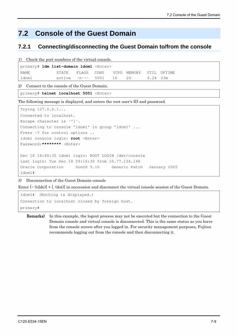
7.2 Console of the Guest Domain
C120-E534-15EN 7-9
7.2 Console of the Guest Domain
7.2.1 Connecting/disconnecting the Guest Domain to/from the console
1) Check the port numbers of the virtual console. primary# ldm list-domain ldom1 <Enter>
NAME STATE FLAGS CONS VCPU MEMORY UTIL UPTIME ldom1 active -n--- 5001 16 2G 6.2% 23m
2) Connect to the console of the Guest Domain. primary# telnet localhost 5001 <Enter>
The following message is displayed, and enters the root user's ID and password.
Trying 127.0.0.1...
Connected to localhost.
Escape character is '^]'.
Connecting to console "ldom1" in group "ldom1" ...
Press ~? for control options .. ldom1 console login: root <Enter> Password:******** <Enter>
Dec 18 16:40:35 ldom1 login: ROOT LOGIN /dev/console
Last login: Tue Dec 18 09:16:30 from 10.77.134.148
Oracle Corporation SunOS 5.10 Generic Patch January 2005
ldom1#
3) Disconnection of the Guest Domain console Enter [~ (tilde)] + [. (dot)] in succession and disconnect the virtual console session of the Guest Domain.
ldom1# (Nothing is displayed.)
Connection to localhost closed by foreign host.
primary#
Remarks) In this example, the logout process may not be executed but the connection to the Guest Domain console and virtual console is disconnected. This is the same status as you leave from the console screen after you logged in. For security management purposes, Fujitsu recommends logging out from the console and then disconnecting it.
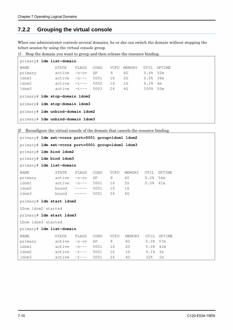
Chapter 7 Operating Logical Domains
7-10 C120-E534-15EN
7.2.2 Grouping the virtual console
When one administrator controls several domains, he or she can switch the domain without stopping the telnet session by using the virtual console group. 1) Stop the domain you want to group and then release the resource binding. primary# ldm list-domain
NAME STATE FLAGS CONS VCPU MEMORY UTIL UPTIME primary active -n-cv SP 8 4G 0.6% 52m ldom1 active -n--- 5001 16 2G 0.0% 36m ldom2 active -t--- 5002 16 1G 6.2% 4m ldom3 active -t--- 5003 24 4G 100% 52m
primary# ldm stop-domain ldom2
primary# ldm stop-domain ldom3
primary# ldm unbind-domain ldom2
primary# ldm unbind-domain ldom3
2) Reconfigure the virtual console of the domain that cancels the resource binding. primary# ldm set-vcons port=5001 group=ldom1 ldom2
primary# ldm set-vcons port=5001 group=ldom1 ldom3
primary# ldm bind ldom2
primary# ldm bind ldom3
primary# ldm list-domain
NAME STATE FLAGS CONS VCPU MEMORY UTIL UPTIME primary active -n-cv SP 8 4G 0.2% 56m ldom1 active -n--- 5001 16 2G 0.0% 41m ldom2 bound ----- 5001 16 1G ldom3 bound ----- 5001 24 4G
primary# ldm start ldom2
LDom ldom2 started
primary# ldm start ldom3
LDom ldom3 started
primary# ldm list-domain
NAME STATE FLAGS CONS VCPU MEMORY UTIL UPTIME primary active -n-cv SP 8 4G 0.3% 57m ldom1 active -n--- 5001 16 2G 0.0% 41m ldom2 active -t--- 5001 16 1G 9.1% 3s ldom3 active -t--- 5001 24 4G 32% 0s
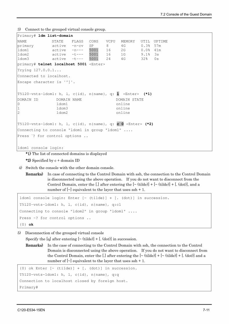
7.2 Console of the Guest Domain
C120-E534-15EN 7-11
3) Connect to the grouped virtual console group. Primary# ldm list-domain
NAME STATE FLAGS CONS VCPU MEMORY UTIL UPTIME primary active -n-cv SP 8 4G 0.3% 57m ldom1 active -n--- 5001 16 2G 0.0% 41m ldom2 active -t--- 5001 16 1G 9.1% 3s ldom3 active -t--- 5001 24 4G 32% 0s primary# telnet localhost 5001 <Enter>
Trying 127.0.0.1...
Connected to localhost.
Escape character is '^]'.
T5120-vnts-ldom1: h, l, c{id}, n{name}, q: l <Enter> (*1)
DOMAIN ID DOMAIN NAME DOMAIN STATE 0 ldom1 online 1 ldom3 online 2 ldom2 online
T5120-vnts-ldom1: h, l, c{id}, n{name}, q: c 0 <Enter> (*2)
Connecting to console "ldom1 in group "ldom1" ....
Press ~? for control options ..
ldom1 console login:
*1) The list of connected domains is displayed *2) Specified by c + domain ID
4) Switch the console with the other domain console. Remarks) In case of connecting to the Control Domain with ssh, the connection to the Control Domain
is disconnected using the above operation. If you do not want to disconnect from the Control Domain, enter the [.] after entering the [~ (tilde)] + [~ (tilde)] + [. (dot)], and a number of [~] equivalent to the layer that uses ssh + 1.
ldom1 console login: Enter [~ (tilde)] + [. (dot)] in succession.
T5120-vnts-ldom1: h, l, c{id}, n{name}, q:c1
Connecting to console "ldom2" in group "ldom1" ....
Press ~? for control options ..
{0} ok
5) Disconnection of the grouped virtual console Specify the [q] after entering [~ (tilde)] + [. (dot)] in succession. Remarks) In the case of connecting to the Control Domain with ssh, the connection to the Control
Domain is disconnected using the above operation. If you do not want to disconnect from the Control Domain, enter the [.] after entering the [~ (tilde)] + [~ (tilde)] + [. (dot)] and a number of [~] equivalent to the layer that uses ssh + 1.
{0} ok Enter [~ (tilde)] + [. (dot)] in succession.
T5120-vnts-ldom1: h, l, c{id}, n{name}, q:q
Connection to localhost closed by foreign host.
Primary#
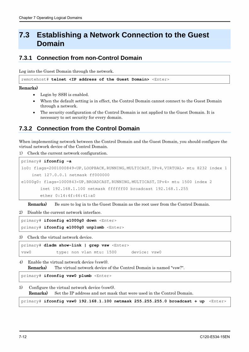
Chapter 7 Operating Logical Domains
7-12 C120-E534-15EN
7.3 Establishing a Network Connection to the Guest Domain
7.3.1 Connection from non-Control Domain
Log into the Guest Domain through the network.
remotehost# telnet <IP address of the Guest Domain> <Enter>
Remarks) • Login by SSH is enabled. • When the default setting is in effect, the Control Domain cannot connect to the Guest Domain
through a network. • The security configuration of the Control Domain is not applied to the Guest Domain. It is
necessary to set security for every domain.
7.3.2 Connection from the Control Domain
When implementing network between the Control Domain and the Guest Domain, you should configure the virtual network device of the Control Domain. 1) Check the current network configuration.
primary# ifconfig -a
lo0: flags=2001000849<UP,LOOPBACK,RUNNING,MULTICAST,IPv4,VIRTUAL> mtu 8232 index 1
inet 127.0.0.1 netmask ff000000
e1000g0: flags=1000843<UP,BROADCAST,RUNNING,MULTICAST,IPv4> mtu 1500 index 2
inet 192.168.1.100 netmask ffffff00 broadcast 192.168.1.255
ether 0:14:4f:46:41:a0
Remarks) Be sure to log in to the Guest Domain as the root user from the Control Domain.
2) Disable the current network interface.
primary# ifconfig e1000g0 down <Enter>
primary# ifconfig e1000g0 unplumb <Enter>
3) Check the virtual network device.
primary# dladm show-link | grep vsw <Enter>
vsw0 type: non vlan mtu: 1500 device: vsw0
4) Enable the virtual network device (vsw0). Remarks) The virtual network device of the Control Domain is named "vsw?".
primary# ifconfig vsw0 plumb <Enter>
5) Configure the virtual network device (vsw0). Remarks) Set the IP address and net mask that were used in the Control Domain.
primary# ifconfig vsw0 192.168.1.100 netmask 255.255.255.0 broadcast + up <Enter>

7.3 Establishing a Network Connection to the Guest Domain
C120-E534-15EN 7-13
6) Check the network configuration. primary# ifconfig -a <Enter>
lo0: flags=2001000849<UP,LOOPBACK,RUNNING,MULTICAST,IPv4,VIRTUAL> mtu 8232 index 1
inet 127.0.0.1 netmask ff000000
vsw0: flags=1000843<UP,BROADCAST,RUNNING,MULTICAST,IPv4> mtu 1500 index 3
inet 192.168.1.100 netmask ffffff00 broadcast 10.77.134.255
ether 0:14:4f:2a:85:70 7) Replace the network definition file. primary# mv /etc/hostname.e1000g0 /etc/hostname.vsw0 <Enter>
Remarks) Check the security setting for the Control Domain before connecting to the server for the Control Domain.
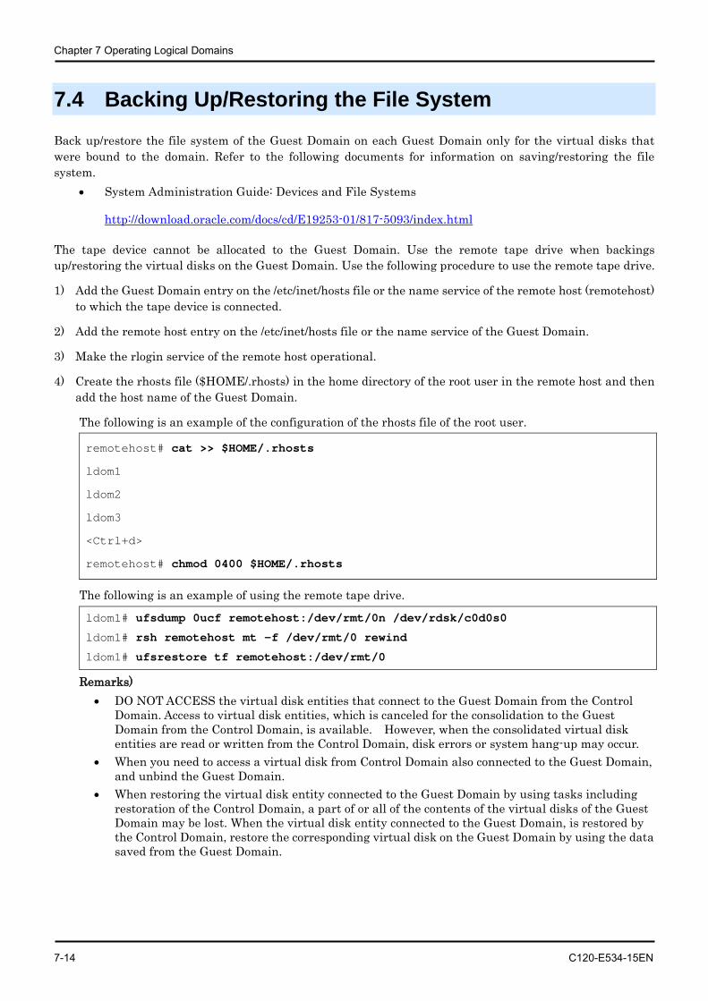
Chapter 7 Operating Logical Domains
7-14 C120-E534-15EN
7.4 Backing Up/Restoring the File System
Back up/restore the file system of the Guest Domain on each Guest Domain only for the virtual disks that were bound to the domain. Refer to the following documents for information on saving/restoring the file system.
• System Administration Guide: Devices and File Systems
http://download.oracle.com/docs/cd/E19253-01/817-5093/index.html
The tape device cannot be allocated to the Guest Domain. Use the remote tape drive when backings up/restoring the virtual disks on the Guest Domain. Use the following procedure to use the remote tape drive.
1) Add the Guest Domain entry on the /etc/inet/hosts file or the name service of the remote host (remotehost) to which the tape device is connected.
2) Add the remote host entry on the /etc/inet/hosts file or the name service of the Guest Domain.
3) Make the rlogin service of the remote host operational.
4) Create the rhosts file ($HOME/.rhosts) in the home directory of the root user in the remote host and then add the host name of the Guest Domain.
The following is an example of the configuration of the rhosts file of the root user.
remotehost# cat >> $HOME/.rhosts
ldom1
ldom2
ldom3
<Ctrl+d>
remotehost# chmod 0400 $HOME/.rhosts
The following is an example of using the remote tape drive.
ldom1# ufsdump 0ucf remotehost:/dev/rmt/0n /dev/rdsk/c0d0s0
ldom1# rsh remotehost mt -f /dev/rmt/0 rewind
ldom1# ufsrestore tf remotehost:/dev/rmt/0
Remarks) • DO NOT ACCESS the virtual disk entities that connect to the Guest Domain from the Control
Domain. Access to virtual disk entities, which is canceled for the consolidation to the Guest Domain from the Control Domain, is available. However, when the consolidated virtual disk entities are read or written from the Control Domain, disk errors or system hang-up may occur.
• When you need to access a virtual disk from Control Domain also connected to the Guest Domain, and unbind the Guest Domain.
• When restoring the virtual disk entity connected to the Guest Domain by using tasks including restoration of the Control Domain, a part of or all of the contents of the virtual disks of the Guest Domain may be lost. When the virtual disk entity connected to the Guest Domain, is restored by the Control Domain, restore the corresponding virtual disk on the Guest Domain by using the data saved from the Guest Domain.
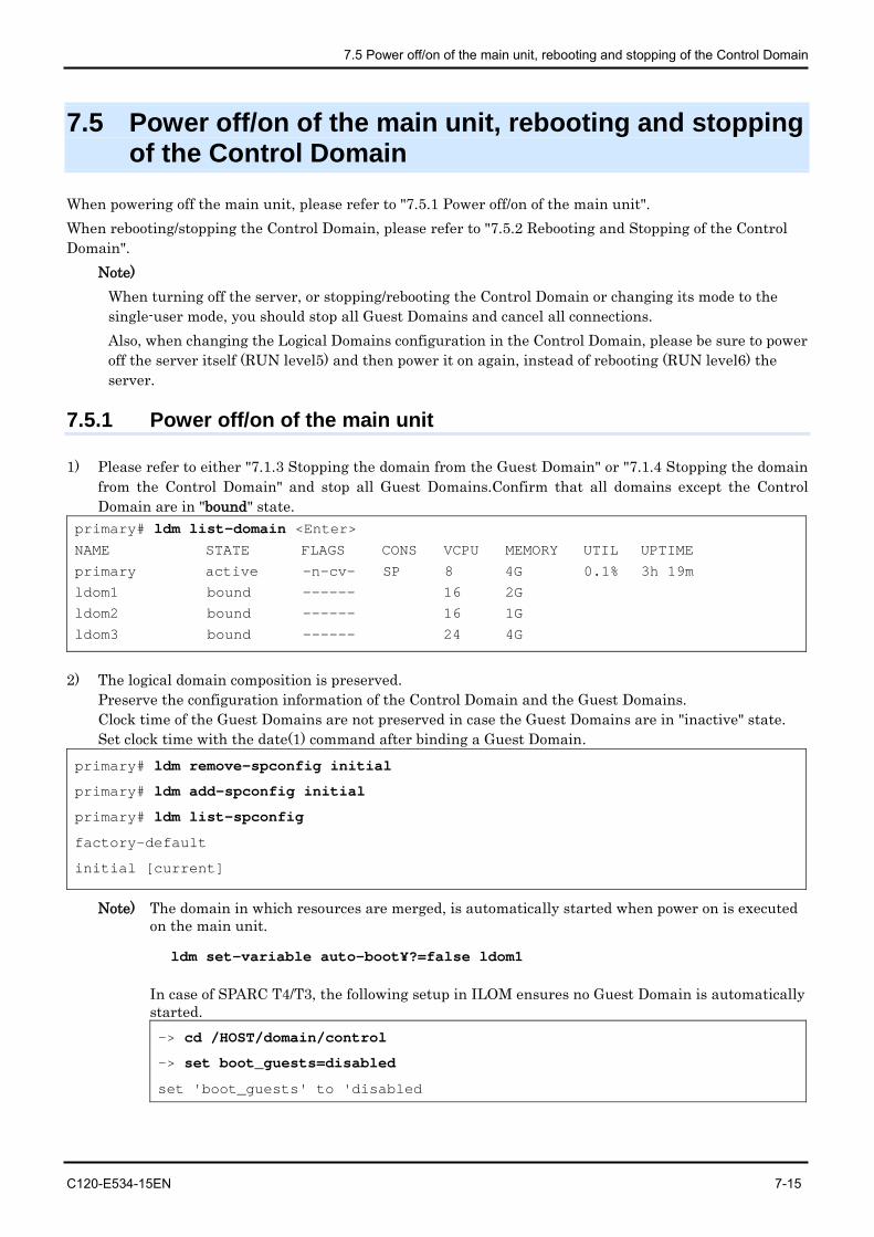
7.5 Power off/on of the main unit, rebooting and stopping of the Control Domain
C120-E534-15EN 7-15
7.5 Power off/on of the main unit, rebooting and stopping of the Control Domain
When powering off the main unit, please refer to "7.5.1 Power off/on of the main unit". When rebooting/stopping the Control Domain, please refer to "7.5.2 Rebooting and Stopping of the Control Domain".
Note) When turning off the server, or stopping/rebooting the Control Domain or changing its mode to the single-user mode, you should stop all Guest Domains and cancel all connections. Also, when changing the Logical Domains configuration in the Control Domain, please be sure to power off the server itself (RUN level5) and then power it on again, instead of rebooting (RUN level6) the server.
7.5.1 Power off/on of the main unit
1) Please refer to either "7.1.3 Stopping the domain from the Guest Domain" or "7.1.4 Stopping the domain from the Control Domain" and stop all Guest Domains.Confirm that all domains except the Control Domain are in "bound" state.
primary# ldm list-domain <Enter> NAME STATE FLAGS CONS VCPU MEMORY UTIL UPTIME
primary active -n-cv- SP 8 4G 0.1% 3h 19m
ldom1 bound ------ 16 2G
ldom2 bound ------ 16 1G
ldom3 bound ------ 24 4G
2) The logical domain composition is preserved. Preserve the configuration information of the Control Domain and the Guest Domains. Clock time of the Guest Domains are not preserved in case the Guest Domains are in "inactive" state. Set clock time with the date(1) command after binding a Guest Domain.
primary# ldm remove-spconfig initial
primary# ldm add-spconfig initial
primary# ldm list-spconfig
factory-default
initial [current]
Note) The domain in which resources are merged, is automatically started when power on is executed on the main unit.
ldm set-variable auto-boot¥?=false ldom1
In case of SPARC T4/T3, the following setup in ILOM ensures no Guest Domain is automatically started. -> cd /HOST/domain/control
-> set boot_guests=disabled
set 'boot_guests' to 'disabled
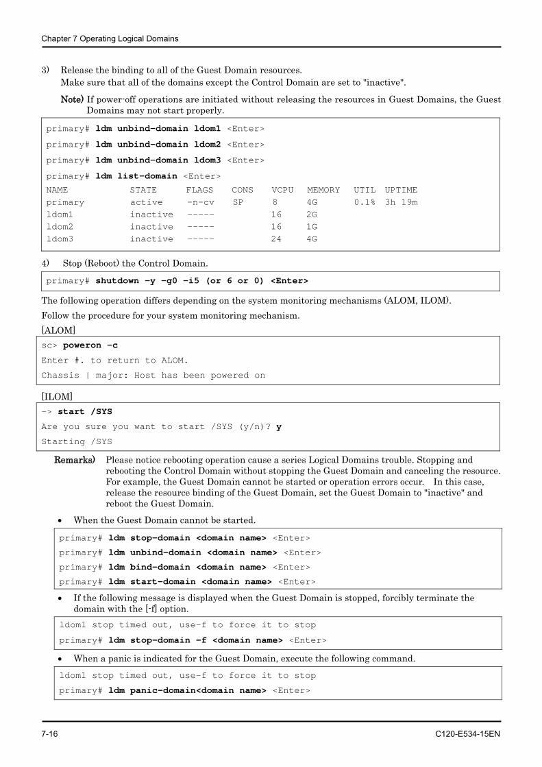
Chapter 7 Operating Logical Domains
7-16 C120-E534-15EN
3) Release the binding to all of the Guest Domain resources. Make sure that all of the domains except the Control Domain are set to "inactive".
Note) If power-off operations are initiated without releasing the resources in Guest Domains, the Guest Domains may not start properly.
primary# ldm unbind-domain ldom1 <Enter>
primary# ldm unbind-domain ldom2 <Enter>
primary# ldm unbind-domain ldom3 <Enter>
primary# ldm list-domain <Enter>
NAME STATE FLAGS CONS VCPU MEMORY UTIL UPTIME primary active -n-cv SP 8 4G 0.1% 3h 19m ldom1 inactive ----- 16 2G ldom2 inactive ----- 16 1G ldom3 inactive ----- 24 4G
4) Stop (Reboot) the Control Domain.
primary# shutdown -y -g0 -i5 (or 6 or 0) <Enter>
The following operation differs depending on the system monitoring mechanisms (ALOM, ILOM). Follow the procedure for your system monitoring mechanism. [ALOM] sc> poweron -c
Enter #. to return to ALOM.
Chassis | major: Host has been powered on
[ILOM] -> start /SYS
Are you sure you want to start /SYS (y/n)? y
Starting /SYS
Remarks) Please notice rebooting operation cause a series Logical Domains trouble. Stopping and rebooting the Control Domain without stopping the Guest Domain and canceling the resource. For example, the Guest Domain cannot be started or operation errors occur. In this case, release the resource binding of the Guest Domain, set the Guest Domain to "inactive" and reboot the Guest Domain.
• When the Guest Domain cannot be started.
primary# ldm stop-domain <domain name> <Enter>
primary# ldm unbind-domain <domain name> <Enter>
primary# ldm bind-domain <domain name> <Enter>
primary# ldm start-domain <domain name> <Enter>
• If the following message is displayed when the Guest Domain is stopped, forcibly terminate the domain with the [-f] option.
ldom1 stop timed out, use-f to force it to stop
primary# ldm stop-domain -f <domain name> <Enter>
• When a panic is indicated for the Guest Domain, execute the following command.
ldom1 stop timed out, use-f to force it to stop
primary# ldm panic-domain<domain name> <Enter>
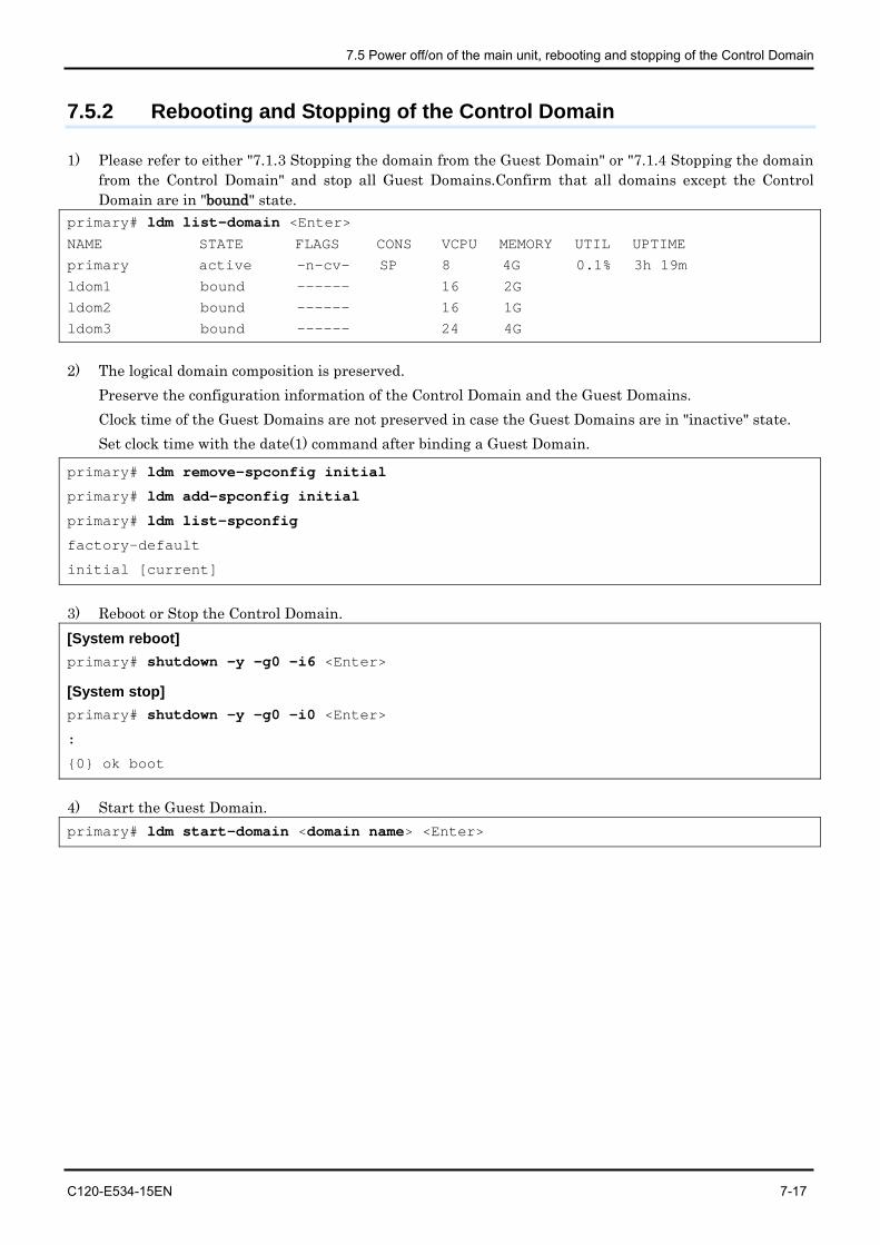
7.5 Power off/on of the main unit, rebooting and stopping of the Control Domain
C120-E534-15EN 7-17
7.5.2 Rebooting and Stopping of the Control Domain
1) Please refer to either "7.1.3 Stopping the domain from the Guest Domain" or "7.1.4 Stopping the domain from the Control Domain" and stop all Guest Domains.Confirm that all domains except the Control Domain are in "bound" state.
primary# ldm list-domain <Enter> NAME STATE FLAGS CONS VCPU MEMORY UTIL UPTIME
primary active -n-cv- SP 8 4G 0.1% 3h 19m
ldom1 bound ------ 16 2G
ldom2 bound ------ 16 1G
ldom3 bound ------ 24 4G
2) The logical domain composition is preserved. Preserve the configuration information of the Control Domain and the Guest Domains. Clock time of the Guest Domains are not preserved in case the Guest Domains are in "inactive" state. Set clock time with the date(1) command after binding a Guest Domain.
primary# ldm remove-spconfig initial
primary# ldm add-spconfig initial
primary# ldm list-spconfig
factory-default
initial [current]
3) Reboot or Stop the Control Domain. [System reboot] primary# shutdown -y -g0 -i6 <Enter>
[System stop] primary# shutdown -y -g0 -i0 <Enter>
:
{0} ok boot
4) Start the Guest Domain. primary# ldm start-domain <domain name> <Enter>
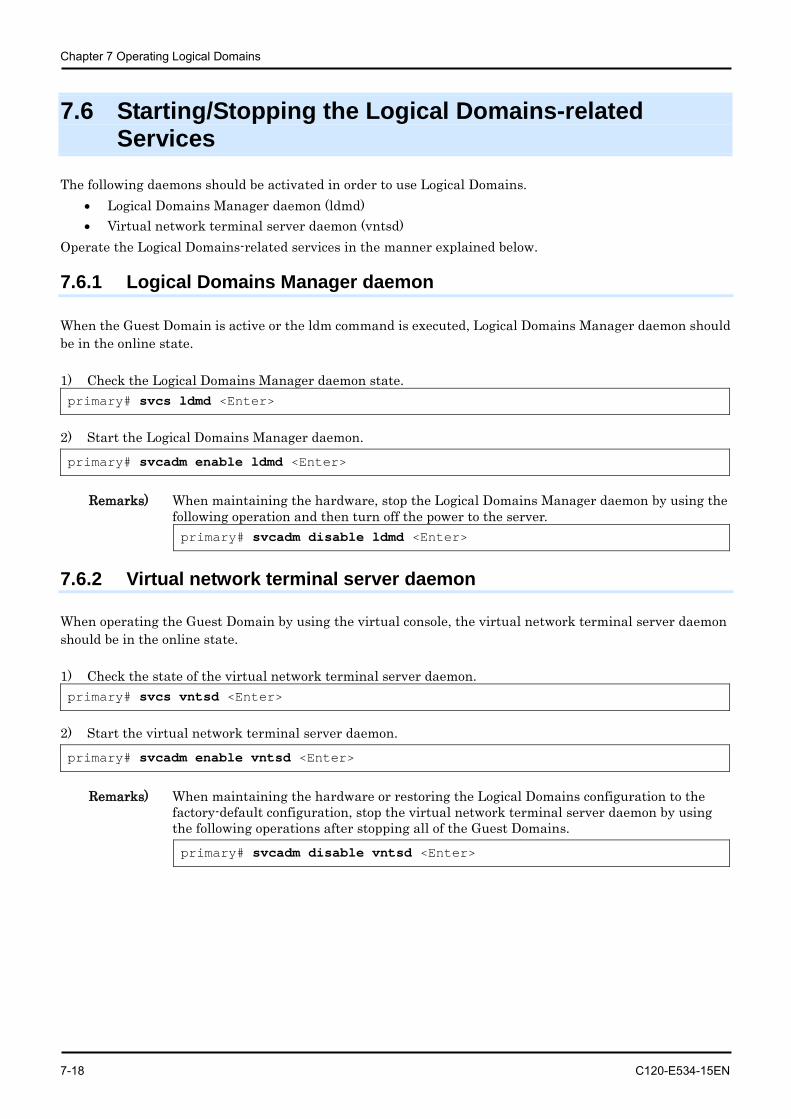
Chapter 7 Operating Logical Domains
7-18 C120-E534-15EN
7.6 Starting/Stopping the Logical Domains-related Services
The following daemons should be activated in order to use Logical Domains. • Logical Domains Manager daemon (ldmd) • Virtual network terminal server daemon (vntsd)
Operate the Logical Domains-related services in the manner explained below.
7.6.1 Logical Domains Manager daemon
When the Guest Domain is active or the ldm command is executed, Logical Domains Manager daemon should be in the online state. 1) Check the Logical Domains Manager daemon state. primary# svcs ldmd <Enter>
2) Start the Logical Domains Manager daemon. primary# svcadm enable ldmd <Enter>
Remarks) When maintaining the hardware, stop the Logical Domains Manager daemon by using the
following operation and then turn off the power to the server. primary# svcadm disable ldmd <Enter>
7.6.2 Virtual network terminal server daemon
When operating the Guest Domain by using the virtual console, the virtual network terminal server daemon should be in the online state. 1) Check the state of the virtual network terminal server daemon. primary# svcs vntsd <Enter>
2) Start the virtual network terminal server daemon. primary# svcadm enable vntsd <Enter>
Remarks) When maintaining the hardware or restoring the Logical Domains configuration to the
factory-default configuration, stop the virtual network terminal server daemon by using the following operations after stopping all of the Guest Domains. primary# svcadm disable vntsd <Enter>
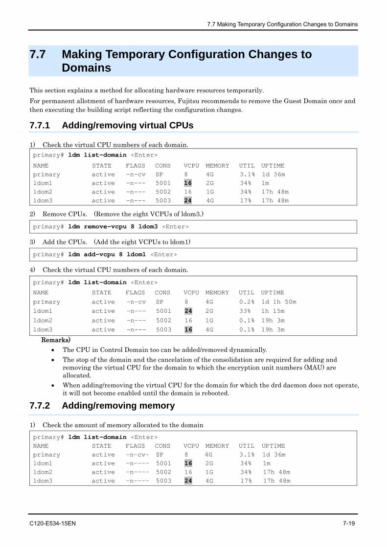
7.7 Making Temporary Configuration Changes to Domains
C120-E534-15EN 7-19
7.7 Making Temporary Configuration Changes to Domains
This section explains a method for allocating hardware resources temporarily. For permanent allotment of hardware resources, Fujitsu recommends to remove the Guest Domain once and then executing the building script reflecting the configuration changes.
7.7.1 Adding/removing virtual CPUs
1) Check the virtual CPU numbers of each domain. primary# ldm list-domain <Enter>
NAME STATE FLAGS CONS VCPU MEMORY UTIL UPTIME primary active -n-cv SP 8 4G 3.1% 1d 36m ldom1 active -n--- 5001 16 2G 34% 1m ldom2 active -n--- 5002 16 1G 34% 17h 48m ldom3 active -n--- 5003 24 4G 17% 17h 48m
2) Remove CPUs. (Remove the eight VCPUs of ldom3.)
primary# ldm remove-vcpu 8 ldom3 <Enter>
3) Add the CPUs. (Add the eight VCPUs to ldom1)
primary# ldm add-vcpu 8 ldom1 <Enter>
4) Check the virtual CPU numbers of each domain.
primary# ldm list-domain <Enter>
NAME STATE FLAGS CONS VCPU MEMORY UTIL UPTIME
primary active -n-cv SP 8 4G 0.2% 1d 1h 50m ldom1 active -n--- 5001 24 2G 33% 1h 15m ldom2 active -n--- 5002 16 1G 0.1% 19h 3m ldom3 active -n--- 5003 16 4G 0.1% 19h 3m
Remarks) • The CPU in Control Domain too can be added/removed dynamically. • The stop of the domain and the cancelation of the consolidation are required for adding and
removing the virtual CPU for the domain to which the encryption unit numbers (MAU) are allocated.
• When adding/removing the virtual CPU for the domain for which the drd daemon does not operate, it will not become enabled until the domain is rebooted.
7.7.2 Adding/removing memory
1) Check the amount of memory allocated to the domain
primary# ldm list-domain <Enter> NAME STATE FLAGS CONS VCPU MEMORY UTIL UPTIME primary active -n-cv- SP 8 4G 3.1% 1d 36m ldom1 active -n---- 5001 16 2G 34% 1m ldom2 active -n---- 5002 16 1G 34% 17h 48m ldom3 active -n---- 5003 24 4G 17% 17h 48m
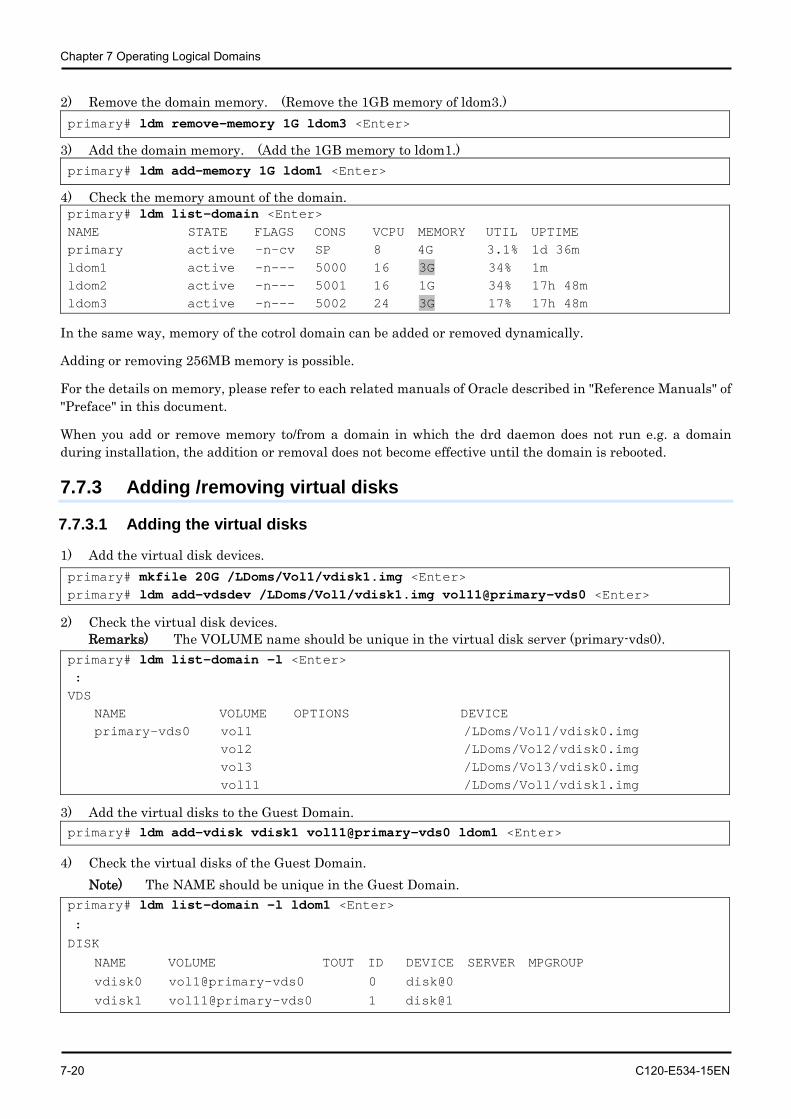
Chapter 7 Operating Logical Domains
7-20 C120-E534-15EN
2) Remove the domain memory. (Remove the 1GB memory of ldom3.) primary# ldm remove-memory 1G ldom3 <Enter>
3) Add the domain memory. (Add the 1GB memory to ldom1.) primary# ldm add-memory 1G ldom1 <Enter>
4) Check the memory amount of the domain. primary# ldm list-domain <Enter> NAME STATE FLAGS CONS VCPU MEMORY UTIL UPTIME primary active -n-cv SP 8 4G 3.1% 1d 36m ldom1 active -n--- 5000 16 3G 34% 1m ldom2 active -n--- 5001 16 1G 34% 17h 48m ldom3 active -n--- 5002 24 3G 17% 17h 48m
In the same way, memory of the cotrol domain can be added or removed dynamically.
Adding or removing 256MB memory is possible.
For the details on memory, please refer to each related manuals of Oracle described in "Reference Manuals" of "Preface" in this document.
When you add or remove memory to/from a domain in which the drd daemon does not run e.g. a domain during installation, the addition or removal does not become effective until the domain is rebooted.
7.7.3 Adding /removing virtual disks
7.7.3.1 Adding the virtual disks
1) Add the virtual disk devices. primary# mkfile 20G /LDoms/Vol1/vdisk1.img <Enter> primary# ldm add-vdsdev /LDoms/Vol1/vdisk1.img vol11@primary-vds0 <Enter>
2) Check the virtual disk devices. Remarks) The VOLUME name should be unique in the virtual disk server (primary-vds0).
primary# ldm list-domain -l <Enter> : VDS NAME VOLUME OPTIONS DEVICE primary-vds0 vol1 /LDoms/Vol1/vdisk0.img vol2 /LDoms/Vol2/vdisk0.img vol3 /LDoms/Vol3/vdisk0.img vol11 /LDoms/Vol1/vdisk1.img
3) Add the virtual disks to the Guest Domain. primary# ldm add-vdisk vdisk1 vol11@primary-vds0 ldom1 <Enter>
4) Check the virtual disks of the Guest Domain. Note) The NAME should be unique in the Guest Domain.
primary# ldm list-domain -l ldom1 <Enter> :
DISK
NAME VOLUME TOUT ID DEVICE SERVER MPGROUP
vdisk0 vol1@primary-vds0 0 disk@0
vdisk1 vol11@primary-vds0 1 disk@1
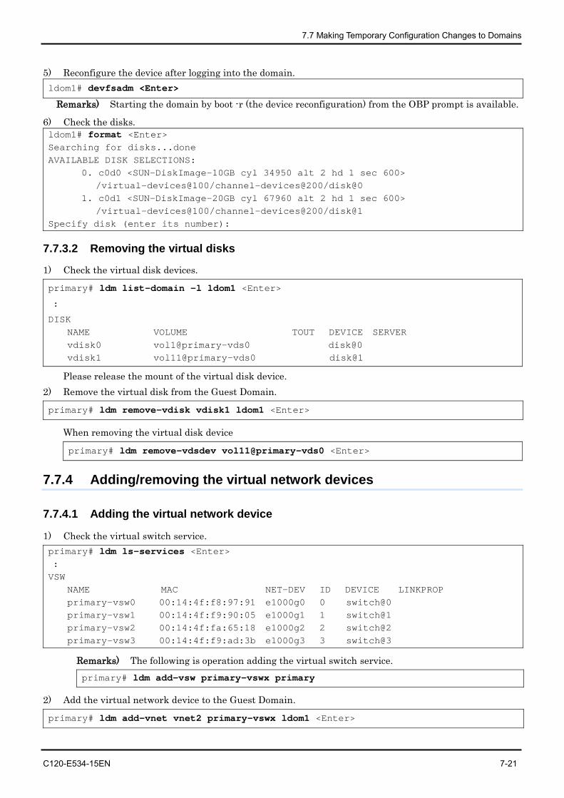
7.7 Making Temporary Configuration Changes to Domains
C120-E534-15EN 7-21
5) Reconfigure the device after logging into the domain. ldom1# devfsadm <Enter>
Remarks) Starting the domain by boot -r (the device reconfiguration) from the OBP prompt is available.
6) Check the disks. ldom1# format <Enter> Searching for disks...done AVAILABLE DISK SELECTIONS: 0. c0d0 <SUN-DiskImage-10GB cyl 34950 alt 2 hd 1 sec 600> /virtual-devices@100/channel-devices@200/disk@0 1. c0d1 <SUN-DiskImage-20GB cyl 67960 alt 2 hd 1 sec 600> /virtual-devices@100/channel-devices@200/disk@1 Specify disk (enter its number):
7.7.3.2 Removing the virtual disks
1) Check the virtual disk devices.
primary# ldm list-domain -l ldom1 <Enter>
:
DISK NAME VOLUME TOUT DEVICE SERVER vdisk0 vol1@primary-vds0 disk@0 vdisk1 vol11@primary-vds0 disk@1
Please release the mount of the virtual disk device. 2) Remove the virtual disk from the Guest Domain.
primary# ldm remove-vdisk vdisk1 ldom1 <Enter>
When removing the virtual disk device
primary# ldm remove-vdsdev vol11@primary-vds0 <Enter>
7.7.4 Adding/removing the virtual network devices
7.7.4.1 Adding the virtual network device
1) Check the virtual switch service. primary# ldm ls-services <Enter> : VSW NAME MAC NET-DEV ID DEVICE LINKPROP primary-vsw0 00:14:4f:f8:97:91 e1000g0 0 switch@0 primary-vsw1 00:14:4f:f9:90:05 e1000g1 1 switch@1 primary-vsw2 00:14:4f:fa:65:18 e1000g2 2 switch@2 primary-vsw3 00:14:4f:f9:ad:3b e1000g3 3 switch@3
Remarks) The following is operation adding the virtual switch service. primary# ldm add-vsw primary-vswx primary
2) Add the virtual network device to the Guest Domain.
primary# ldm add-vnet vnet2 primary-vswx ldom1 <Enter>
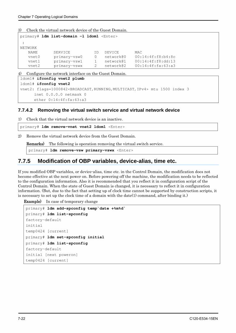
Chapter 7 Operating Logical Domains
7-22 C120-E534-15EN
3) Check the virtual network device of the Guest Domain. primary# ldm list-domain -l ldom1 <Enter>
: NETWORK NAME SERVICE ID DEVICE MAC vnet0 primary-vsw0 0 network@0 00:14:4f:f8:b4:8c vnet1 primary-vsw1 1 network@1 00:14:4f:f8:dd:13 vnet2 primary-vswx 2 network@2 00:14:4f:fa:63:a3
4) Configure the network interface on the Guest Domain. ldom1# ifconfig vnet2 plumb ldom1# ifconfig vnet2 vnet2: flags=1000842<BROADCAST,RUNNING,MULTICAST,IPv4> mtu 1500 index 3 inet 0.0.0.0 netmask 0 ether 0:14:4f:fa:63:a3
7.7.4.2 Removing the virtual switch service and virtual network device
1) Check that the virtual network device is an inactive.
primary# ldm remove-vnet vnet2 ldom1 <Enter>
2) Remove the virtual network device from the Guest Domain.
Remarks) The following is operation removing the virtual switch service. primary# ldm remove-vsw primary-vswx <Enter>
7.7.5 Modification of OBP variables, device-alias, time etc.
If you modified OBP variables, or device-alias, time etc. in the Control Domain, the modification does not become effective at the next power on. Before powering off the machine, the modification needs to be reflected to the configuration information. Also it is recommended that you reflect it in configuration script of the Control Domain. When the state of Guest Domain is changed, it is necessary to reflect it in configuration information. (But, due to the fact that setting up of clock time cannot be supported by construction scripts, it is necessary to set up the clock time of a domain with the date(1) command, after binding it.)
Example) In case of temporary change primary# ldm add-spconfig temp`date +%m%d` primary# ldm list-spconfig factory-default
initial
temp0424 [current]
primary# ldm set-spconfig initial
primary# ldm list-spconfig factory-default
initial [next poweron]
temp0424 [current]
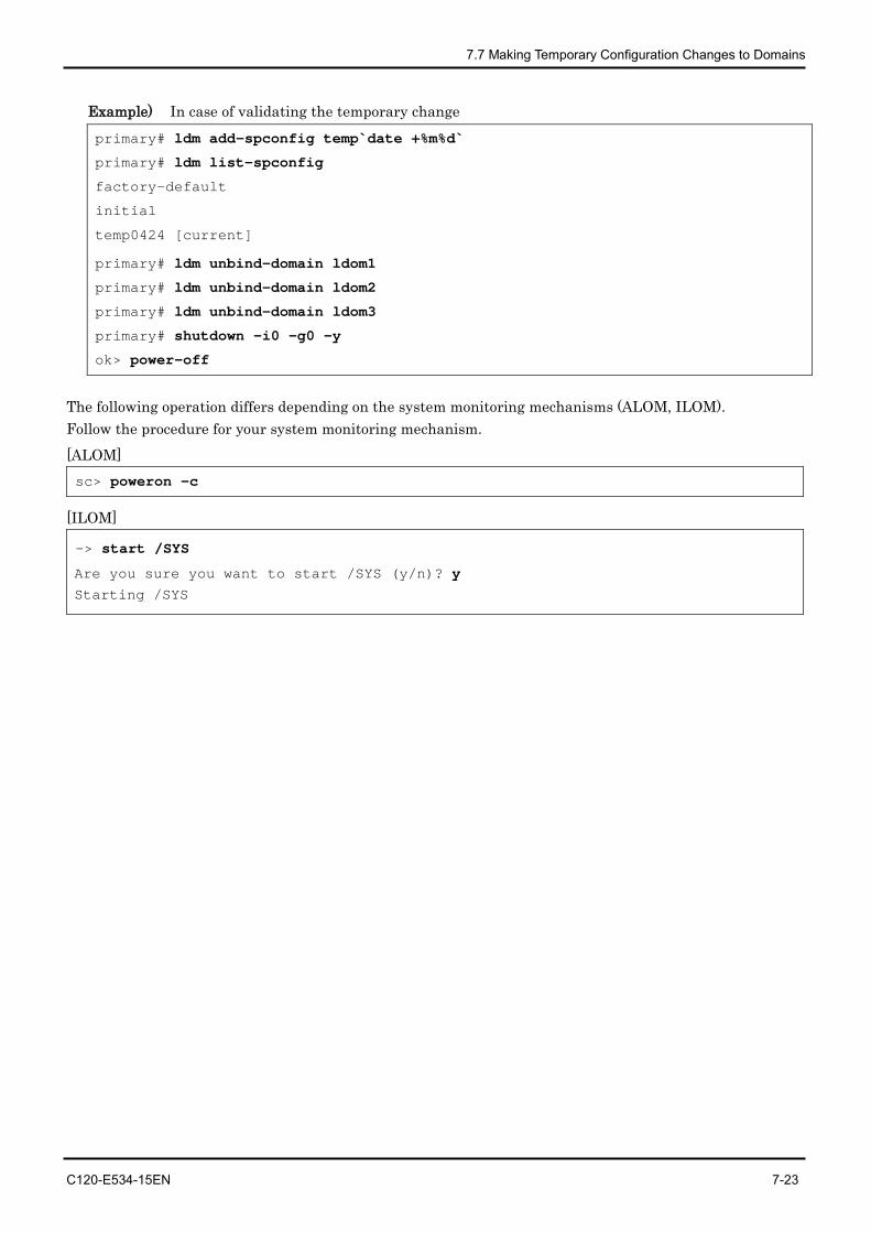
7.7 Making Temporary Configuration Changes to Domains
C120-E534-15EN 7-23
Example) In case of validating the temporary change primary# ldm add-spconfig temp`date +%m%d`
primary# ldm list-spconfig
factory-default
initial
temp0424 [current]
primary# ldm unbind-domain ldom1
primary# ldm unbind-domain ldom2
primary# ldm unbind-domain ldom3
primary# shutdown -i0 -g0 -y
ok> power-off
The following operation differs depending on the system monitoring mechanisms (ALOM, ILOM). Follow the procedure for your system monitoring mechanism. [ALOM] sc> poweron -c
[ILOM]
-> start /SYS
Are you sure you want to start /SYS (y/n)? y Starting /SYS
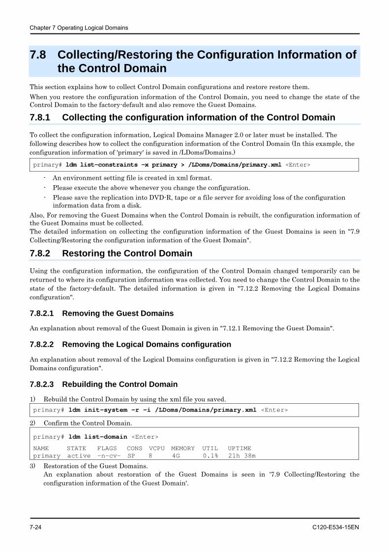
Chapter 7 Operating Logical Domains
7-24 C120-E534-15EN
7.8 Collecting/Restoring the Configuration Information of the Control Domain
This section explains how to collect Control Domain configurations and restore restore them. When you restore the configuration information of the Control Domain, you need to change the state of the Control Domain to the factory-default and also remove the Guest Domains.
7.8.1 Collecting the configuration information of the Control Domain
To collect the configuration information, Logical Domains Manager 2.0 or later must be installed. The following describes how to collect the configuration information of the Control Domain (In this example, the configuration information of 'primary' is saved in /LDoms/Domains.)
primary# ldm list-constraints -x primary > /LDoms/Domains/primary.xml <Enter>
- An environment setting file is created in xml format. - Please execute the above whenever you change the configuration. - Please save the replication into DVD-R, tape or a file server for avoiding loss of the configuration
information data from a disk. Also, For removing the Guest Domains when the Control Domain is rebuilt, the configuration information of the Guest Domains must be collected. The detailed information on collecting the configuration information of the Guest Domains is seen in "7.9 Collecting/Restoring the configuration information of the Guest Domain".
7.8.2 Restoring the Control Domain
Using the configuration information, the configuration of the Control Domain changed temporarily can be returned to where its configuration information was collected. You need to change the Control Domain to the state of the factory-default. The detailed information is given in "7.12.2 Removing the Logical Domains configuration".
7.8.2.1 Removing the Guest Domains
An explanation about removal of the Guest Domain is given in "7.12.1 Removing the Guest Domain".
7.8.2.2 Removing the Logical Domains configuration
An explanation about removal of the Logical Domains configuration is given in "7.12.2 Removing the Logical Domains configuration".
7.8.2.3 Rebuilding the Control Domain
1) Rebuild the Control Domain by using the xml file you saved. primary# ldm init-system -r -i /LDoms/Domains/primary.xml <Enter>
2) Confirm the Control Domain.
primary# ldm list-domain <Enter>
NAME STATE FLAGS CONS VCPU MEMORY UTIL UPTIME primary active -n-cv- SP 8 4G 0.1% 21h 38m
3) Restoration of the Guest Domains. An explanation about restoration of the Guest Domains is seen in '7.9 Collecting/Restoring the configuration information of the Guest Domain'.
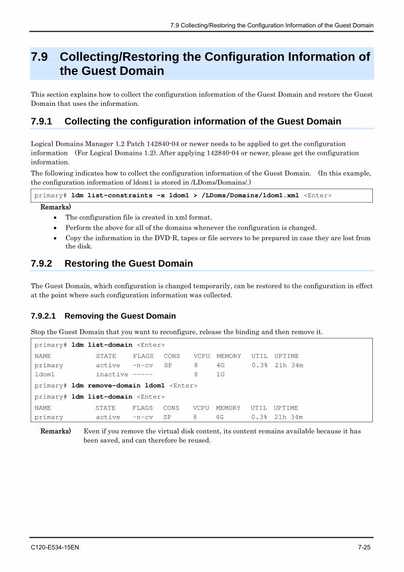
7.9 Collecting/Restoring the Configuration Information of the Guest Domain
C120-E534-15EN 7-25
7.9 Collecting/Restoring the Configuration Information of the Guest Domain
This section explains how to collect the configuration information of the Guest Domain and restore the Guest Domain that uses the information.
7.9.1 Collecting the configuration information of the Guest Domain
Logical Domains Manager 1.2 Patch 142840-04 or newer needs to be applied to get the configuration information (For Logical Domains 1.2). After applying 142840-04 or newer, please get the configuration information. The following indicates how to collect the configuration information of the Guest Domain. (In this example, the configuration information of ldom1 is stored in /LDoms/Domains/.)
primary# ldm list-constraints -x ldom1 > /LDoms/Domains/ldom1.xml <Enter>
Remarks) • The configuration file is created in xml format. • Perform the above for all of the domains whenever the configuration is changed. • Copy the information in the DVD-R, tapes or file servers to be prepared in case they are lost from
the disk.
7.9.2 Restoring the Guest Domain
The Guest Domain, which configuration is changed temporarily, can be restored to the configuration in effect at the point where such configuration information was collected.
7.9.2.1 Removing the Guest Domain
Stop the Guest Domain that you want to reconfigure, release the binding and then remove it.
primary# ldm list-domain <Enter>
NAME STATE FLAGS CONS VCPU MEMORY UTIL UPTIME primary active -n-cv SP 8 4G 0.3% 21h 34m ldom1 inactive ----- 8 1G
primary# ldm remove-domain ldom1 <Enter>
primary# ldm list-domain <Enter>
NAME STATE FLAGS CONS VCPU MEMORY UTIL UPTIME primary active -n-cv SP 8 4G 0.3% 21h 34m
Remarks) Even if you remove the virtual disk content, its content remains available because it has been saved, and can therefore be reused.
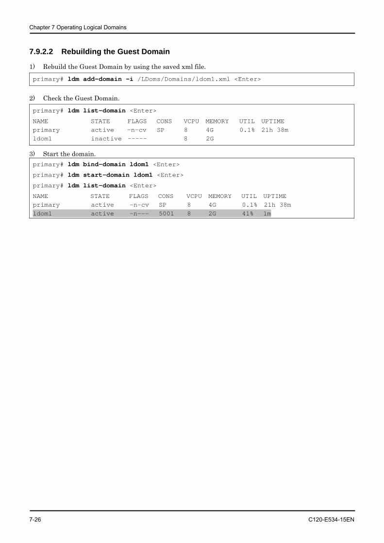
Chapter 7 Operating Logical Domains
7-26 C120-E534-15EN
7.9.2.2 Rebuilding the Guest Domain
1) Rebuild the Guest Domain by using the saved xml file.
primary# ldm add-domain -i /LDoms/Domains/ldom1.xml <Enter>
2) Check the Guest Domain.
primary# ldm list-domain <Enter>
NAME STATE FLAGS CONS VCPU MEMORY UTIL UPTIME primary active -n-cv SP 8 4G 0.1% 21h 38m ldom1 inactive ----- 8 2G
3) Start the domain. primary# ldm bind-domain ldom1 <Enter>
primary# ldm start-domain ldom1 <Enter>
primary# ldm list-domain <Enter>
NAME STATE FLAGS CONS VCPU MEMORY UTIL UPTIME primary active -n-cv SP 8 4G 0.1% 21h 38m ldom1 active -n--- 5001 8 2G 41% 1m
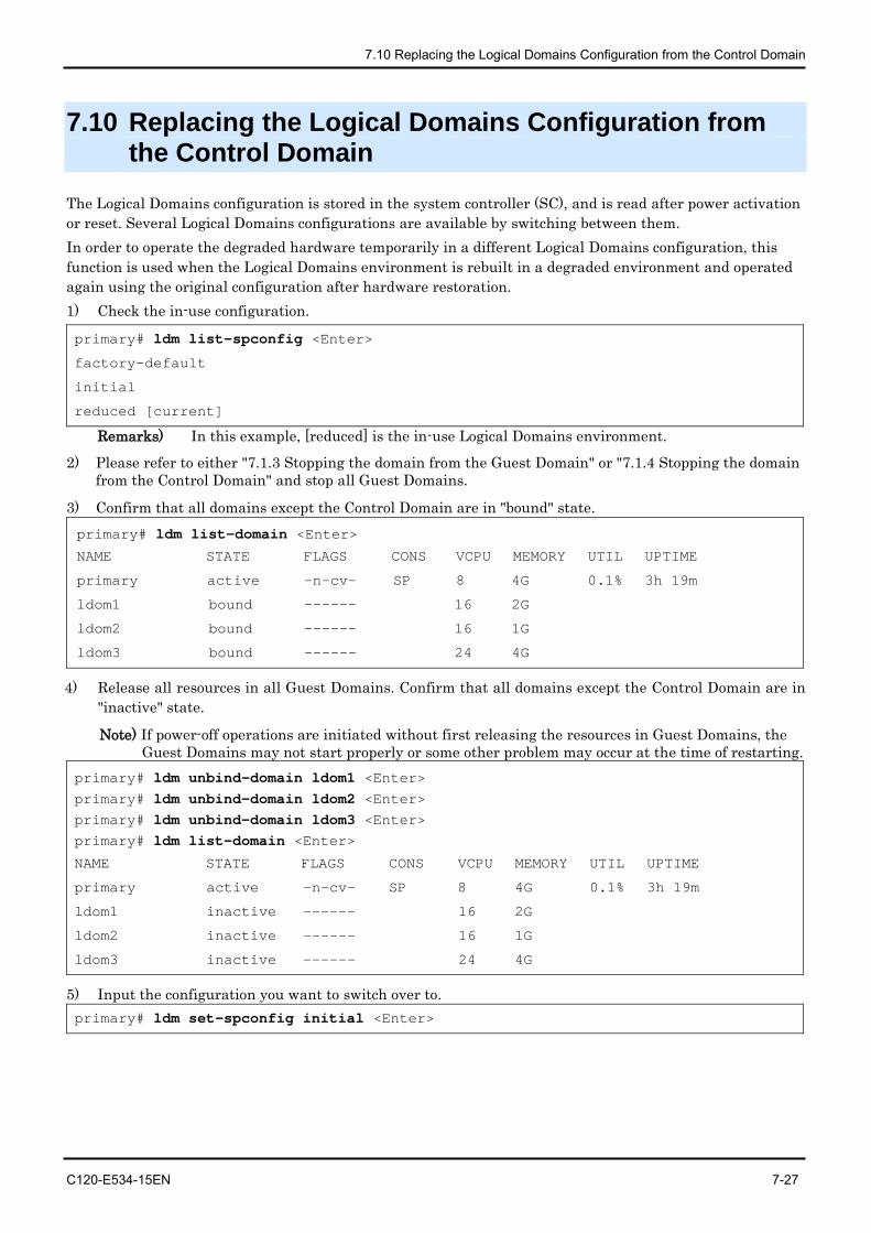
7.10 Replacing the Logical Domains Configuration from the Control Domain
C120-E534-15EN 7-27
7.10 Replacing the Logical Domains Configuration from the Control Domain
The Logical Domains configuration is stored in the system controller (SC), and is read after power activation or reset. Several Logical Domains configurations are available by switching between them. In order to operate the degraded hardware temporarily in a different Logical Domains configuration, this function is used when the Logical Domains environment is rebuilt in a degraded environment and operated again using the original configuration after hardware restoration. 1) Check the in-use configuration.
primary# ldm list-spconfig <Enter>
factory-default
initial
reduced [current] Remarks) In this example, [reduced] is the in-use Logical Domains environment.
2) Please refer to either "7.1.3 Stopping the domain from the Guest Domain" or "7.1.4 Stopping the domain from the Control Domain" and stop all Guest Domains.
3) Confirm that all domains except the Control Domain are in "bound" state. primary# ldm list-domain <Enter>
NAME STATE FLAGS CONS VCPU MEMORY UTIL UPTIME
primary active -n-cv- SP 8 4G 0.1% 3h 19m
ldom1 bound ------ 16 2G
ldom2 bound ------ 16 1G
ldom3 bound ------ 24 4G
4) Release all resources in all Guest Domains. Confirm that all domains except the Control Domain are in "inactive" state.
Note) If power-off operations are initiated without first releasing the resources in Guest Domains, the Guest Domains may not start properly or some other problem may occur at the time of restarting.
primary# ldm unbind-domain ldom1 <Enter> primary# ldm unbind-domain ldom2 <Enter> primary# ldm unbind-domain ldom3 <Enter> primary# ldm list-domain <Enter>
NAME STATE FLAGS CONS VCPU MEMORY UTIL UPTIME
primary active -n-cv- SP 8 4G 0.1% 3h 19m
ldom1 inactive ------ 16 2G
ldom2 inactive ------ 16 1G
ldom3 inactive ------ 24 4G
5) Input the configuration you want to switch over to. primary# ldm set-spconfig initial <Enter>
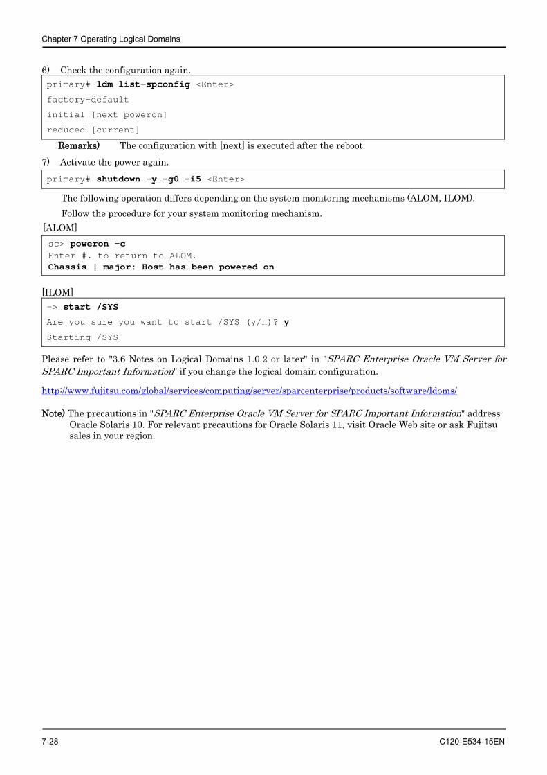
Chapter 7 Operating Logical Domains
7-28 C120-E534-15EN
6) Check the configuration again. primary# ldm list-spconfig <Enter>
factory-default
initial [next poweron]
reduced [current] Remarks) The configuration with [next] is executed after the reboot.
7) Activate the power again. primary# shutdown -y -g0 -i5 <Enter>
The following operation differs depending on the system monitoring mechanisms (ALOM, ILOM). Follow the procedure for your system monitoring mechanism.
[ALOM] sc> poweron -c Enter #. to return to ALOM. Chassis | major: Host has been powered on
[ILOM] -> start /SYS
Are you sure you want to start /SYS (y/n)? y
Starting /SYS
Please refer to "3.6 Notes on Logical Domains 1.0.2 or later" in "SPARC Enterprise Oracle VM Server for SPARC Important Information" if you change the logical domain configuration.
http://www.fujitsu.com/global/services/computing/server/sparcenterprise/products/software/ldoms/
Note) The precautions in "SPARC Enterprise Oracle VM Server for SPARC Important Information" address Oracle Solaris 10. For relevant precautions for Oracle Solaris 11, visit Oracle Web site or ask Fujitsu sales in your region.
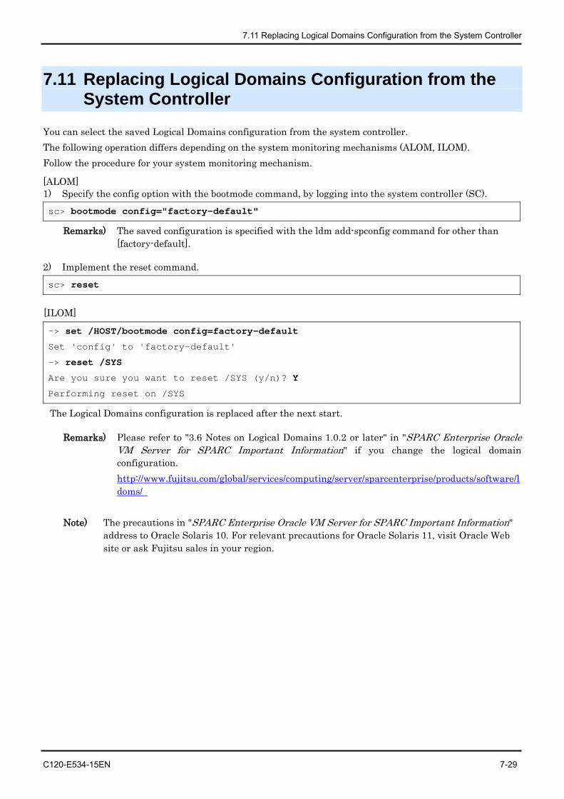
7.11 Replacing Logical Domains Configuration from the System Controller
C120-E534-15EN 7-29
7.11 Replacing Logical Domains Configuration from the System Controller
You can select the saved Logical Domains configuration from the system controller. The following operation differs depending on the system monitoring mechanisms (ALOM, ILOM). Follow the procedure for your system monitoring mechanism.
[ALOM] 1) Specify the config option with the bootmode command, by logging into the system controller (SC). sc> bootmode config="factory-default"
Remarks) The saved configuration is specified with the ldm add-spconfig command for other than [factory-default].
2) Implement the reset command.
sc> reset
[ILOM]
-> set /HOST/bootmode config=factory-default
Set 'config' to 'factory-default'
-> reset /SYS
Are you sure you want to reset /SYS (y/n)? Y
Performing reset on /SYS
The Logical Domains configuration is replaced after the next start.
Remarks) Please refer to "3.6 Notes on Logical Domains 1.0.2 or later" in "SPARC Enterprise Oracle VM Server for SPARC Important Information" if you change the logical domain configuration. http://www.fujitsu.com/global/services/computing/server/sparcenterprise/products/software/ldoms/
Note) The precautions in "SPARC Enterprise Oracle VM Server for SPARC Important Information" address to Oracle Solaris 10. For relevant precautions for Oracle Solaris 11, visit Oracle Web site or ask Fujitsu sales in your region.
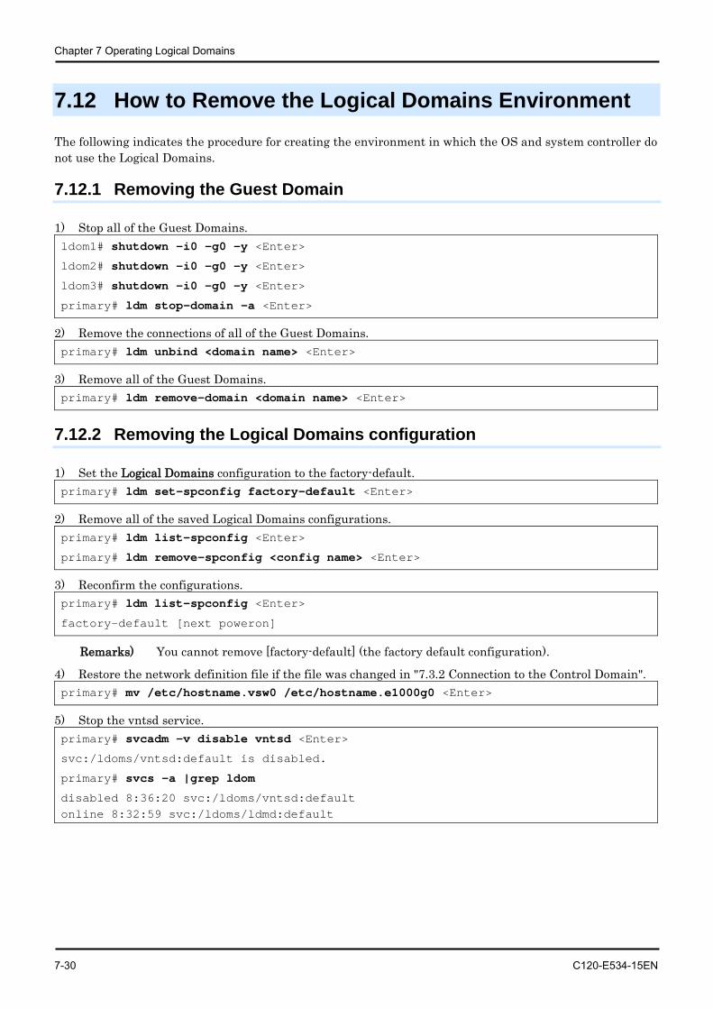
Chapter 7 Operating Logical Domains
7-30 C120-E534-15EN
7.12 How to Remove the Logical Domains Environment
The following indicates the procedure for creating the environment in which the OS and system controller do not use the Logical Domains.
7.12.1 Removing the Guest Domain
1) Stop all of the Guest Domains. ldom1# shutdown -i0 -g0 -y <Enter>
ldom2# shutdown -i0 -g0 -y <Enter>
ldom3# shutdown -i0 -g0 -y <Enter>
primary# ldm stop-domain -a <Enter>
2) Remove the connections of all of the Guest Domains. primary# ldm unbind <domain name> <Enter>
3) Remove all of the Guest Domains. primary# ldm remove-domain <domain name> <Enter>
7.12.2 Removing the Logical Domains configuration
1) Set the Logical Domains configuration to the factory-default. primary# ldm set-spconfig factory-default <Enter>
2) Remove all of the saved Logical Domains configurations. primary# ldm list-spconfig <Enter>
primary# ldm remove-spconfig <config name> <Enter>
3) Reconfirm the configurations. primary# ldm list-spconfig <Enter>
factory-default [next poweron]
Remarks) You cannot remove [factory-default] (the factory default configuration).
4) Restore the network definition file if the file was changed in "7.3.2 Connection to the Control Domain". primary# mv /etc/hostname.vsw0 /etc/hostname.e1000g0 <Enter>
5) Stop the vntsd service. primary# svcadm -v disable vntsd <Enter>
svc:/ldoms/vntsd:default is disabled.
primary# svcs -a |grep ldom
disabled 8:36:20 svc:/ldoms/vntsd:default online 8:32:59 svc:/ldoms/ldmd:default
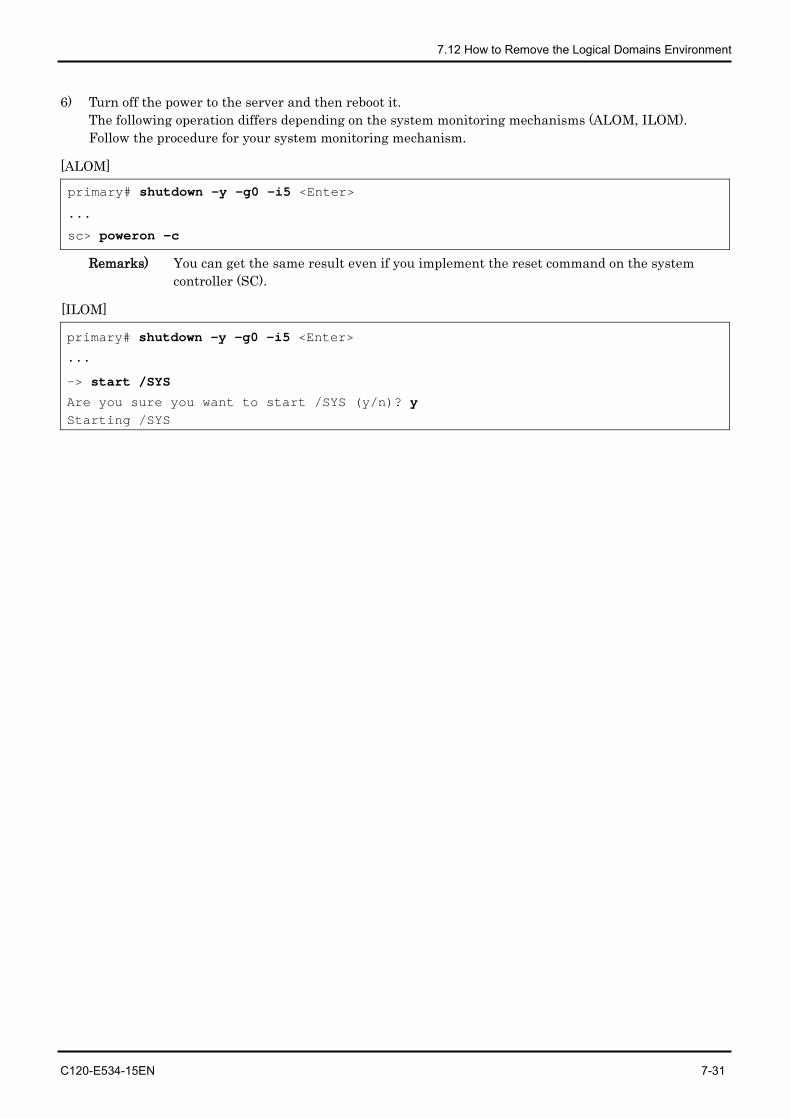
7.12 How to Remove the Logical Domains Environment
C120-E534-15EN 7-31
6) Turn off the power to the server and then reboot it. The following operation differs depending on the system monitoring mechanisms (ALOM, ILOM). Follow the procedure for your system monitoring mechanism.
[ALOM]
primary# shutdown -y -g0 -i5 <Enter>
...
sc> poweron -c
Remarks) You can get the same result even if you implement the reset command on the system controller (SC).
[ILOM]
primary# shutdown -y -g0 -i5 <Enter>
...
-> start /SYS
Are you sure you want to start /SYS (y/n)? y Starting /SYS
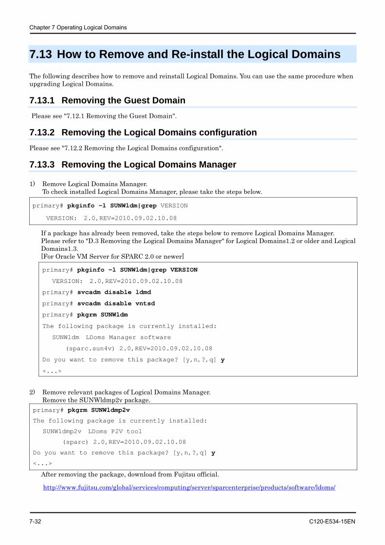
Chapter 7 Operating Logical Domains
7-32 C120-E534-15EN
7.13 How to Remove and Re-install the Logical Domains The following describes how to remove and reinstall Logical Domains. You can use the same procedure when upgrading Logical Domains.
7.13.1 Removing the Guest Domain Please see "7.12.1 Removing the Guest Domain".
7.13.2 Removing the Logical Domains configuration Please see "7.12.2 Removing the Logical Domains configuration".
7.13.3 Removing the Logical Domains Manager
1) Remove Logical Domains Manager. To check installed Logical Domains Manager, please take the steps below.
primary# pkginfo -l SUNWldm|grep VERSION
VERSION: 2.0,REV=2010.09.02.10.08
If a package has already been removed, take the steps below to remove Logical Domains Manager. Please refer to "D.3 Removing the Logical Domains Manager" for Logical Domains1.2 or older and Logical Domains1.3. [For Oracle VM Server for SPARC 2.0 or newer]
primary# pkginfo -l SUNWldm|grep VERSION
VERSION: 2.0,REV=2010.09.02.10.08
primary# svcadm disable ldmd
primary# svcadm disable vntsd
primary# pkgrm SUNWldm
The following package is currently installed:
SUNWldm LDoms Manager software
(sparc.sun4v) 2.0,REV=2010.09.02.10.08
Do you want to remove this package? [y,n,?,q] y
<...>
2) Remove relevant packages of Logical Domains Manager.
Remove the SUNWldmp2v package. primary# pkgrm SUNWldmp2v
The following package is currently installed:
SUNWldmp2v LDoms P2V tool
(sparc) 2.0,REV=2010.09.02.10.08
Do you want to remove this package? [y,n,?,q] y
<...> After removing the package, download from Fujitsu official.
http://www.fujitsu.com/global/services/computing/server/sparcenterprise/products/software/ldoms/
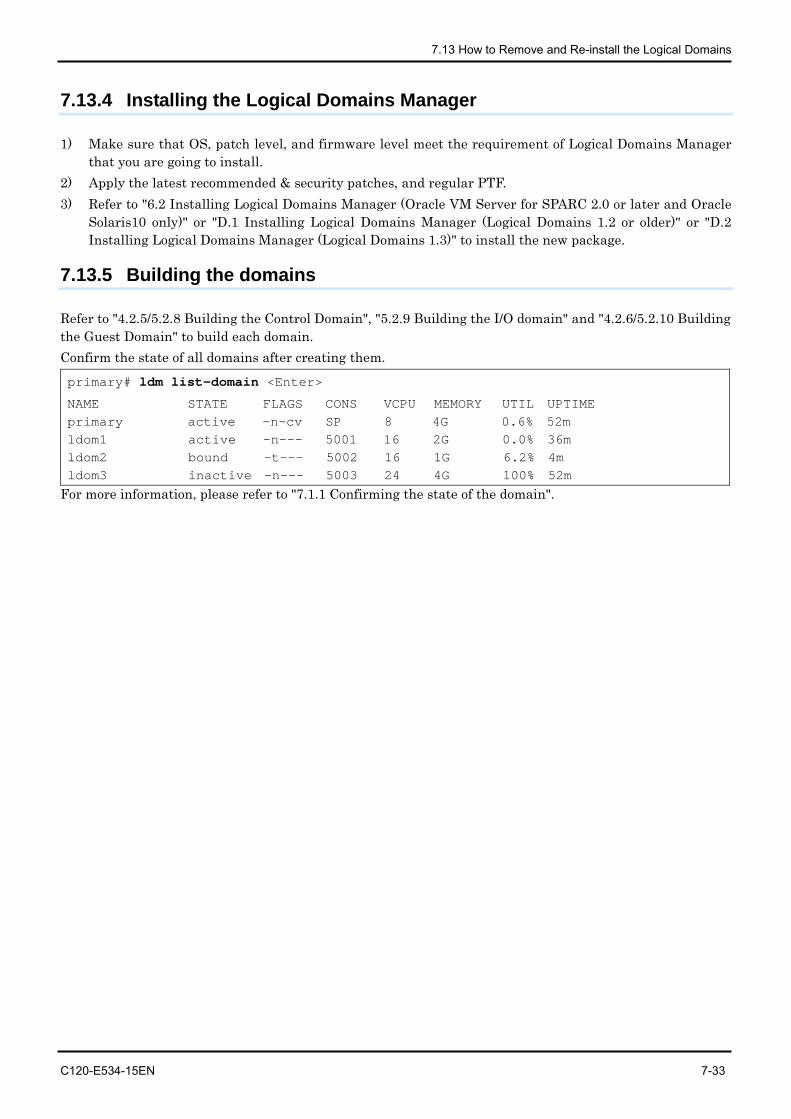
7.13 How to Remove and Re-install the Logical Domains
C120-E534-15EN 7-33
7.13.4 Installing the Logical Domains Manager
1) Make sure that OS, patch level, and firmware level meet the requirement of Logical Domains Manager that you are going to install.
2) Apply the latest recommended & security patches, and regular PTF. 3) Refer to "6.2 Installing Logical Domains Manager (Oracle VM Server for SPARC 2.0 or later and Oracle
Solaris10 only)" or "D.1 Installing Logical Domains Manager (Logical Domains 1.2 or older)" or "D.2 Installing Logical Domains Manager (Logical Domains 1.3)" to install the new package.
7.13.5 Building the domains
Refer to "4.2.5/5.2.8 Building the Control Domain", "5.2.9 Building the I/O domain" and "4.2.6/5.2.10 Building the Guest Domain" to build each domain. Confirm the state of all domains after creating them. primary# ldm list-domain <Enter>
NAME STATE FLAGS CONS VCPU MEMORY UTIL UPTIME primary active -n-cv SP 8 4G 0.6% 52m ldom1 active -n--- 5001 16 2G 0.0% 36m ldom2 bound -t--- 5002 16 1G 6.2% 4m ldom3 inactive -n--- 5003 24 4G 100% 52m
For more information, please refer to "7.1.1 Confirming the state of the domain".
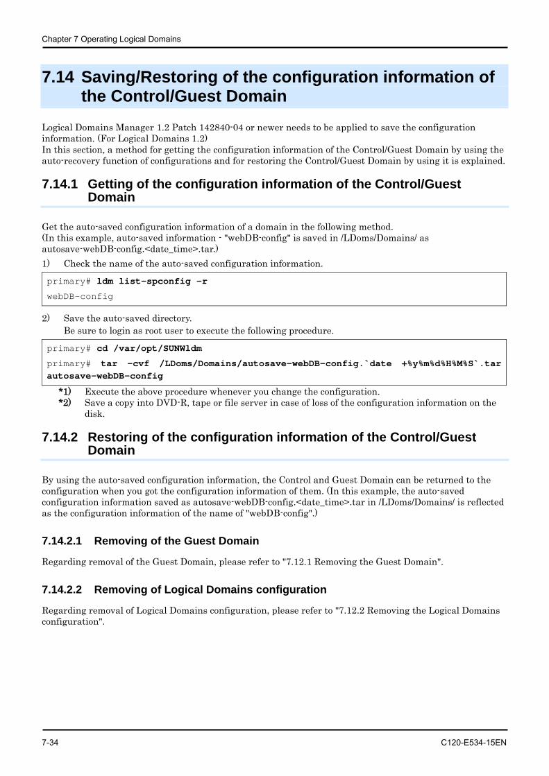
Chapter 7 Operating Logical Domains
7-34 C120-E534-15EN
7.14 Saving/Restoring of the configuration information of the Control/Guest Domain
Logical Domains Manager 1.2 Patch 142840-04 or newer needs to be applied to save the configuration information. (For Logical Domains 1.2) In this section, a method for getting the configuration information of the Control/Guest Domain by using the auto-recovery function of configurations and for restoring the Control/Guest Domain by using it is explained.
7.14.1 Getting of the configuration information of the Control/Guest Domain
Get the auto-saved configuration information of a domain in the following method. (In this example, auto-saved information - "webDB-config" is saved in /LDoms/Domains/ as autosave-webDB-config.<date_time>.tar.) 1) Check the name of the auto-saved configuration information.
primary# ldm list-spconfig -r
webDB-config
2) Save the auto-saved directory. Be sure to login as root user to execute the following procedure.
primary# cd /var/opt/SUNWldm
primary# tar -cvf /LDoms/Domains/autosave-webDB-config.`date +%y%m%d%H%M%S`.tar autosave-webDB-config
*1) Execute the above procedure whenever you change the configuration. *2) Save a copy into DVD-R, tape or file server in case of loss of the configuration information on the
disk.
7.14.2 Restoring of the configuration information of the Control/Guest Domain
By using the auto-saved configuration information, the Control and Guest Domain can be returned to the configuration when you got the configuration information of them. (In this example, the auto-saved configuration information saved as autosave-webDB-config.<date_time>.tar in /LDoms/Domains/ is reflected as the configuration information of the name of "webDB-config".)
7.14.2.1 Removing of the Guest Domain
Regarding removal of the Guest Domain, please refer to "7.12.1 Removing the Guest Domain".
7.14.2.2 Removing of Logical Domains configuration
Regarding removal of Logical Domains configuration, please refer to "7.12.2 Removing the Logical Domains configuration".
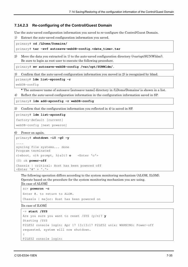
7.14 Saving/Restoring of the configuration information of the Control/Guest Domain
C120-E534-15EN 7-35
7.14.2.3 Re-configuring of the Control/Guest Domain
Use the auto-saved configuration information you saved to re-configure the Control/Guest Domain. 1) Extract the auto-saved configuration information you saved.
primary# cd /LDoms/Domains/
primary# tar -xvf autosave-webDB-config.<date_time>.tar
2) Move the data you extracted in 1) to the auto-saved configuration directory (/var/opt/SUNWldm/). Be sure to login as root user to execute the following procedure.
primary# mv autosave-webDB-config /var/opt/SUNWldm/.
3) Confirm that the auto-saved configuration information you moved in 2) is recognized by ldmd. primary# ldm list-spconfig -r
webDB-config * The autosave-name of autosave-[autosave-name] directory in /LDoms/Domains/ is shown in a list.
4) Reflect the auto-saved configuration information in the configuration information saved in SP.
primary# ldm add-spconfig -r webDB-config
5) Confirm that the configuration information you reflected in 4) is saved in SP.
primary# ldm list-spconfig
factory-default [current]
webDB-config [next poweron]
6) Power on again. primary# shutdown -i0 -g0 -y
.... syncing file systems... done Program terminated
r)eboot, o)k prompt, h)alt? o <Enter "o">
{0} ok power-off
Chassis | critical: Host has been powered off <Enter "#" + ".">
The following operation differs according to the system monitoring mechanism (ALOM, ILOM). Operate based on the procedure for the system monitoring mechanism you are using. [In case of ALOM] sc> poweron -c
Enter #. to return to ALOM.
Chassis | major: Host has been powered on
[In case of ILOM] -> start /SYS Are you sure you want to reset /SYS (y/n)? y Starting /SYS
P2LE52 console login: Apr 17 13:13:17 P2LE52 unix: WARNING: Power-off
requested, system will now shutdown.
:
P2LE52 console login:
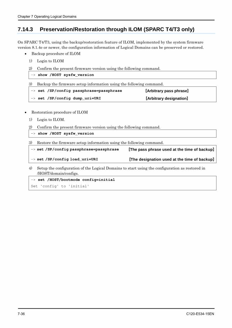
Chapter 7 Operating Logical Domains
7-36 C120-E534-15EN
7.14.3 Preservation/Restoration through ILOM (SPARC T4/T3 only)
On SPARC T4/T3, using the backup/restoration feature of ILOM, implemented by the system firmware version 8.1.4e or newer, the configuration information of Logical Domains can be preserved or restored.
• Backup procedure of ILOM
1) Login to ILOM
2) Confirm the present firmware version using the following command. -> show /HOST sysfw_version
3) Backup the firmware setup information using the following command. -> set /SP/config passphrase=passphrase [Arbitrary pass phrase]
-> set /SP/config dump_uri=URI [Arbitrary designation]
• Restoration procedure of ILOM
1) Login to ILOM.
2) Confirm the present firmware version using the following command. -> show /HOST sysfw_version
3) Restore the firmware setup information using the following command. -> set /SP/config passphrase=passphrase [The pass phrase used at the time of backup]
-> set /SP/config load_uri=URI [The designation used at the time of backup]
4) Setup the configuration of the Logical Domains to start using the configuration as restored in /HOST/domain/configs.
-> set /HOST/bootmode config=initial
Set 'config' to 'initial'
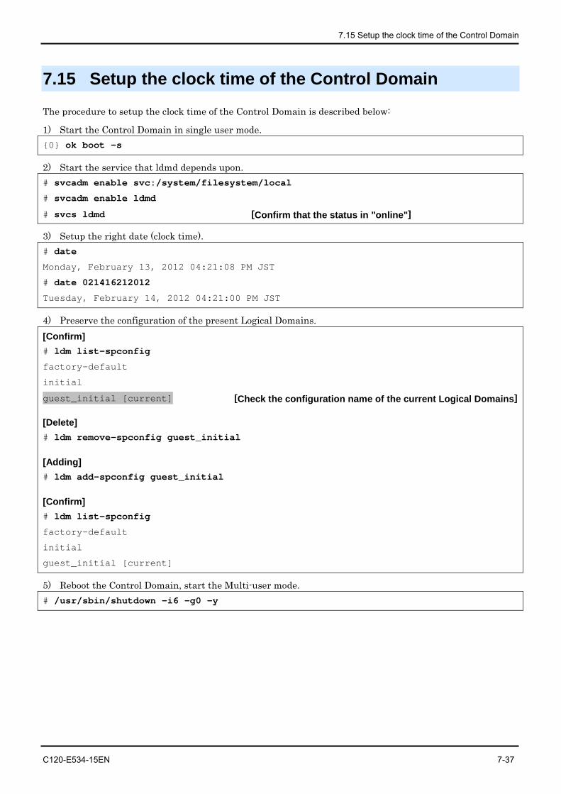
7.15 Setup the clock time of the Control Domain
C120-E534-15EN 7-37
7.15 Setup the clock time of the Control Domain
The procedure to setup the clock time of the Control Domain is described below:
1) Start the Control Domain in single user mode. {0} ok boot -s
2) Start the service that ldmd depends upon. # svcadm enable svc:/system/filesystem/local
# svcadm enable ldmd
# svcs ldmd [Confirm that the status in "online"]
3) Setup the right date (clock time). # date
Monday, February 13, 2012 04:21:08 PM JST
# date 021416212012
Tuesday, February 14, 2012 04:21:00 PM JST
4) Preserve the configuration of the present Logical Domains. [Confirm] # ldm list-spconfig
factory-default
initial
guest_initial [current] [Check the configuration name of the current Logical Domains]
[Delete] # ldm remove-spconfig guest_initial
[Adding] # ldm add-spconfig guest_initial
[Confirm] # ldm list-spconfig
factory-default
initial
guest_initial [current]
5) Reboot the Control Domain, start the Multi-user mode. # /usr/sbin/shutdown -i6 -g0 -y
C120-E534-15EN 8-1
Chapter 8 Tasks Required to Replace Parts This chapter, will discuss about the chores on the customer's side at the time of replacement of SPARC Enterprise T5120/T5220/T5140/T5240/T5440 server components by a service engineer. After replacing the motherboard and BSP board and SCC module, the factory-default settings of the Logical Domains environment become effective. Observe the following procedures in the order given: "8.2 Stopping the System Before Replacing Parts" and "8.3 Building Logical Domains after Replacing Parts". Moreover, on SPARC T3 server and above, the Logical Domains configuration information is contained in the backup of ILOM configuration information. Please refer to manuals published by Oracle or please contact to below for the procedure of backing up/restoration of Logical Domains configuration information.
• SPARC Enterprise contacts http://www.fujitsu.com/global/contact/computing/sparce_index.html
8.1 Parts Replacement Performed by the Service Engineer
Your service engineer must replace the parts in the device-deactivated state and check their operations which include the POST completion of the Control Domain.
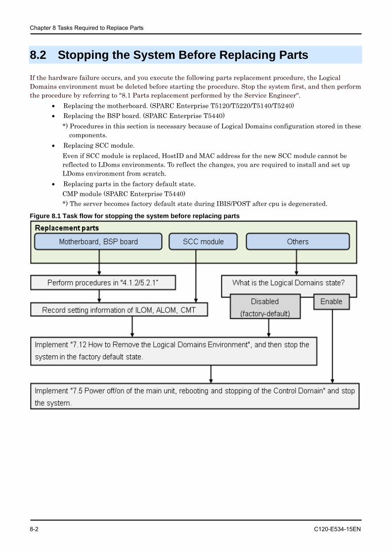
Chapter 8 Tasks Required to Replace Parts
8-2 C120-E534-15EN
8.2 Stopping the System Before Replacing Parts
If the hardware failure occurs, and you execute the following parts replacement procedure, the Logical Domains environment must be deleted before starting the procedure. Stop the system first, and then perform the procedure by referring to "8.1 Parts replacement performed by the Service Engineer".
• Replacing the motherboard. (SPARC Enterprise T5120/T5220/T5140/T5240) • Replacing the BSP board. (SPARC Enterprise T5440)
*) Procedures in this section is necessary because of Logical Domains configuration stored in these components.
• Replacing SCC module. Even if SCC module is replaced, HostID and MAC address for the new SCC module cannot be reflected to LDoms environments. To reflect the changes, you are required to install and set up LDoms environment from scratch.
• Replacing parts in the factory default state. CMP module (SPARC Enterprise T5440) *) The server becomes factory default state during IBIS/POST after cpu is degenerated.
Figure 8.1 Task flow for stopping the system before replacing parts
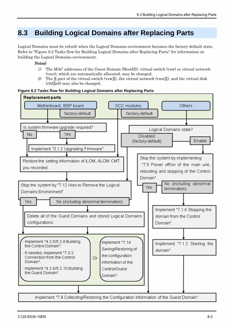
8.3 Building Logical Domains after Replacing Parts
C120-E534-15EN 8-3
8.3 Building Logical Domains after Replacing Parts
Logical Domains must be rebuilt when the Logical Domains environment becomes the factory-default state. Refer to "Figure 8.2 Tasks flow for Building Logical Domains after Replacing Parts" for information on building the Logical Domains environment.
Notes) 1) The MAC addresses of the Guest Domain (HostID), virtual switch (vsw) or virtual network
(vnet), which are automatically allocated, may be changed. 2) The X part of the virtual switch (vswX), the virtual network (vnetX), and the virtual disk
(c0dXs0) may also be changed.
Figure 8.2 Tasks flow for Building Logical Domains after Replacing Parts
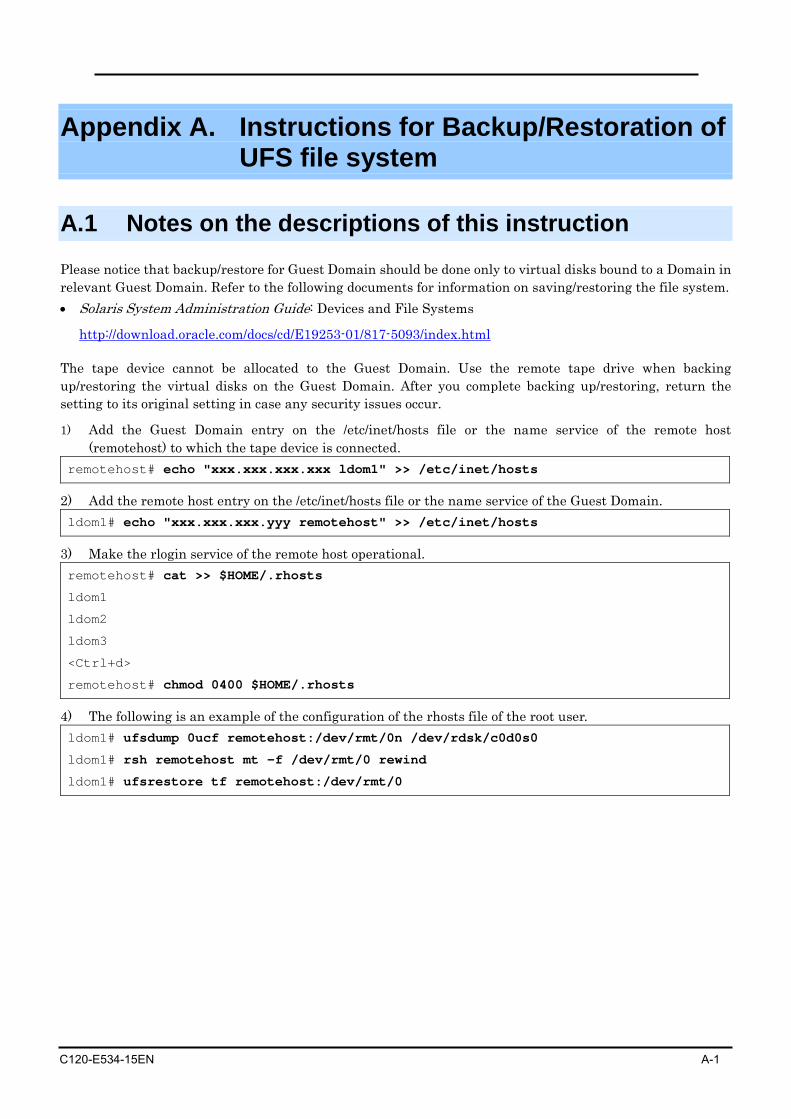
C120-E534-15EN A-1
Appendix A. Instructions for Backup/Restoration of UFS file system
A.1 Notes on the descriptions of this instruction
Please notice that backup/restore for Guest Domain should be done only to virtual disks bound to a Domain in relevant Guest Domain. Refer to the following documents for information on saving/restoring the file system. • Solaris System Administration Guide: Devices and File Systems
http://download.oracle.com/docs/cd/E19253-01/817-5093/index.html
The tape device cannot be allocated to the Guest Domain. Use the remote tape drive when backing up/restoring the virtual disks on the Guest Domain. After you complete backing up/restoring, return the setting to its original setting in case any security issues occur.
1) Add the Guest Domain entry on the /etc/inet/hosts file or the name service of the remote host (remotehost) to which the tape device is connected.
remotehost# echo "xxx.xxx.xxx.xxx ldom1" >> /etc/inet/hosts
2) Add the remote host entry on the /etc/inet/hosts file or the name service of the Guest Domain. ldom1# echo "xxx.xxx.xxx.yyy remotehost" >> /etc/inet/hosts
3) Make the rlogin service of the remote host operational. remotehost# cat >> $HOME/.rhosts
ldom1
ldom2
ldom3
<Ctrl+d>
remotehost# chmod 0400 $HOME/.rhosts
4) The following is an example of the configuration of the rhosts file of the root user. ldom1# ufsdump 0ucf remotehost:/dev/rmt/0n /dev/rdsk/c0d0s0
ldom1# rsh remotehost mt -f /dev/rmt/0 rewind
ldom1# ufsrestore tf remotehost:/dev/rmt/0
A.1 Notes on the descriptions of this instruction
A-2 C120-E534-15EN
The Control Domain can access virtual disk entities if they are released from binding a Domain. However, if the bound virtual disk entities are read or written from the Control Domain, disk errors or system hang-up sometimes occur in a Guest Domain. Therefore, DO NOT ACCESS the virtual disk entities that bound to the Guest Domain from the Control Domain. When accessing a virtual disk from the Control Domain bound to the Guest Domain, stop the Guest Domain and unbind it from the Control Domain. When restoring the virtual disk entity bound to the Guest Domain by using tasks such as restoration of the Control Domain, a part of or all of the contents of the virtual disks of the Guest Domain may be lost. When the virtual disk entity, which is connected to the Guest Domain, is restored by the Control Domain, restore the counterpart virtual disk on the Guest Domain by using the save data from the Guest Domain. Instructions on how to collect VTOC information
ldom1# prtvtoc /dev/rdsk/c#t#d#s2 > file
Note) file: the name of a file saving VTOC information
If you cannot allocate an emergency boot disk, you can boot the system from a network server to continue your work.
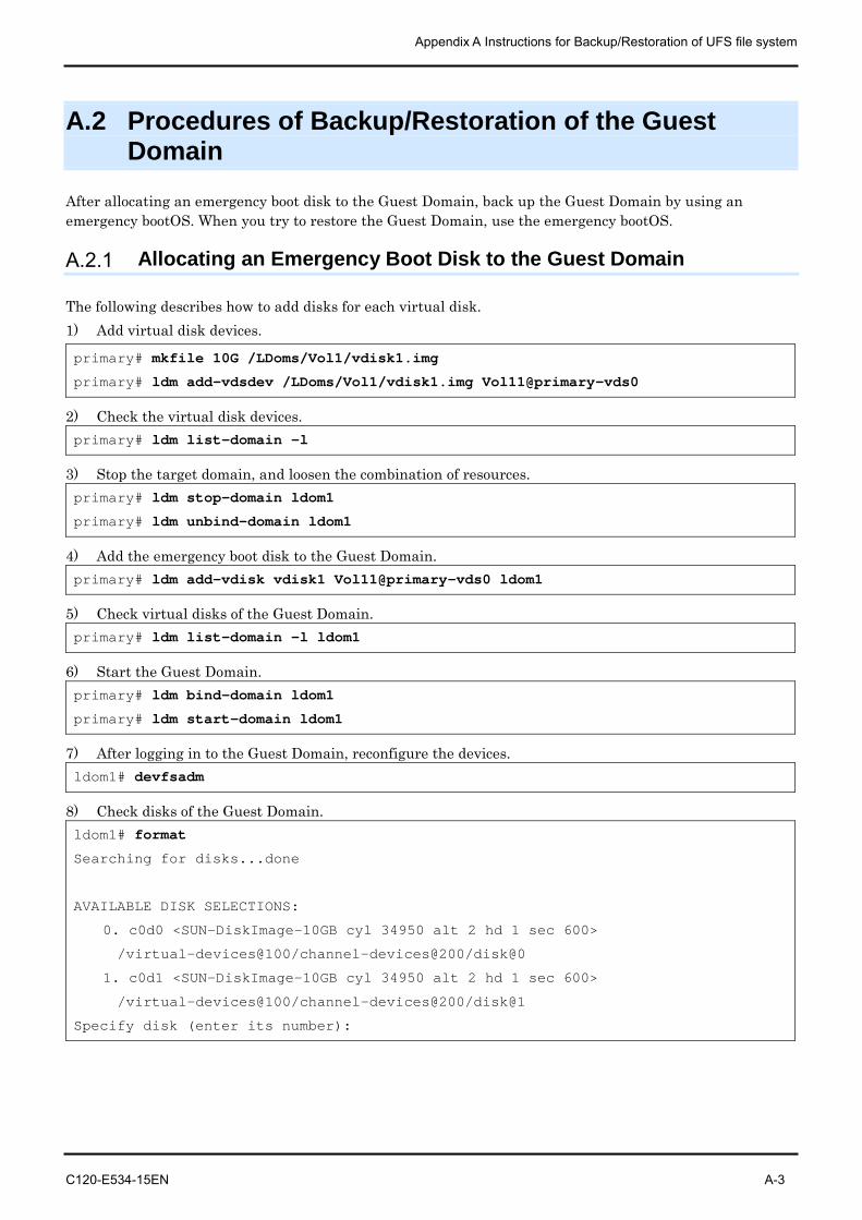
Appendix A Instructions for Backup/Restoration of UFS file system
C120-E534-15EN A-3
A.2 Procedures of Backup/Restoration of the Guest Domain
After allocating an emergency boot disk to the Guest Domain, back up the Guest Domain by using an emergency bootOS. When you try to restore the Guest Domain, use the emergency bootOS.
A.2.1 Allocating an Emergency Boot Disk to the Guest Domain
The following describes how to add disks for each virtual disk. 1) Add virtual disk devices.
primary# mkfile 10G /LDoms/Vol1/vdisk1.img
primary# ldm add-vdsdev /LDoms/Vol1/vdisk1.img Vol11@primary-vds0
2) Check the virtual disk devices. primary# ldm list-domain -l
3) Stop the target domain, and loosen the combination of resources. primary# ldm stop-domain ldom1
primary# ldm unbind-domain ldom1
4) Add the emergency boot disk to the Guest Domain. primary# ldm add-vdisk vdisk1 Vol11@primary-vds0 ldom1
5) Check virtual disks of the Guest Domain. primary# ldm list-domain -l ldom1
6) Start the Guest Domain. primary# ldm bind-domain ldom1
primary# ldm start-domain ldom1
7) After logging in to the Guest Domain, reconfigure the devices. ldom1# devfsadm
8) Check disks of the Guest Domain. ldom1# format
Searching for disks...done
AVAILABLE DISK SELECTIONS:
0. c0d0 <SUN-DiskImage-10GB cyl 34950 alt 2 hd 1 sec 600>
/virtual-devices@100/channel-devices@200/disk@0
1. c0d1 <SUN-DiskImage-10GB cyl 34950 alt 2 hd 1 sec 600>
/virtual-devices@100/channel-devices@200/disk@1
Specify disk (enter its number):
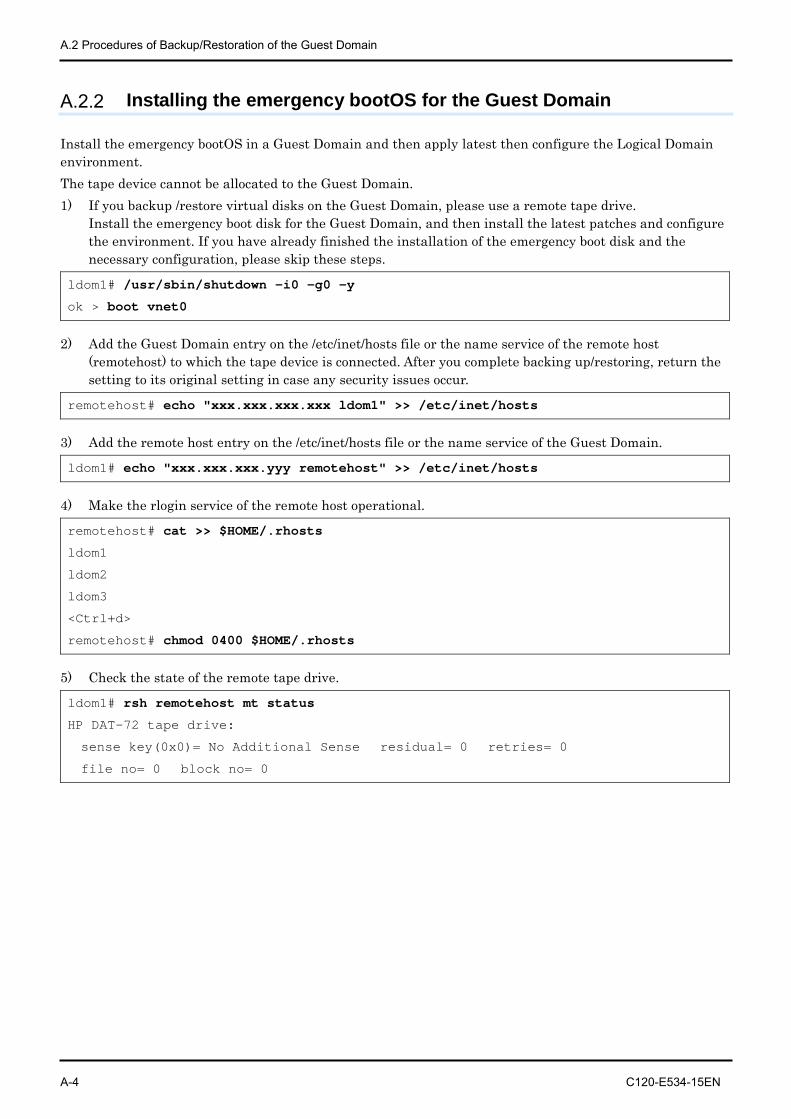
A.2 Procedures of Backup/Restoration of the Guest Domain
A-4 C120-E534-15EN
A.2.2 Installing the emergency bootOS for the Guest Domain
Install the emergency bootOS in a Guest Domain and then apply latest then configure the Logical Domain environment. The tape device cannot be allocated to the Guest Domain. 1) If you backup /restore virtual disks on the Guest Domain, please use a remote tape drive.
Install the emergency boot disk for the Guest Domain, and then install the latest patches and configure the environment. If you have already finished the installation of the emergency boot disk and the necessary configuration, please skip these steps.
ldom1# /usr/sbin/shutdown -i0 -g0 –y
ok > boot vnet0
2) Add the Guest Domain entry on the /etc/inet/hosts file or the name service of the remote host
(remotehost) to which the tape device is connected. After you complete backing up/restoring, return the setting to its original setting in case any security issues occur.
remotehost# echo "xxx.xxx.xxx.xxx ldom1" >> /etc/inet/hosts
3) Add the remote host entry on the /etc/inet/hosts file or the name service of the Guest Domain.
ldom1# echo "xxx.xxx.xxx.yyy remotehost" >> /etc/inet/hosts
4) Make the rlogin service of the remote host operational.
remotehost# cat >> $HOME/.rhosts
ldom1
ldom2
ldom3
<Ctrl+d>
remotehost# chmod 0400 $HOME/.rhosts
5) Check the state of the remote tape drive.
ldom1# rsh remotehost mt status
HP DAT-72 tape drive:
sense key(0x0)= No Additional Sense residual= 0 retries= 0
file no= 0 block no= 0
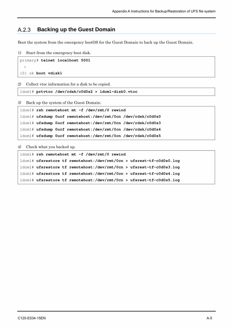
Appendix A Instructions for Backup/Restoration of UFS file system
C120-E534-15EN A-5
A.2.3 Backing up the Guest Domain
Boot the system from the emergency bootOS for the Guest Domain to back up the Guest Domain. 1) Start from the emergency boot disk.
primary# telnet localhost 5001
:
{0} ok boot vdisk1
2) Collect vtoc information for a disk to be copied.
ldom1# prtvtoc /dev/rdsk/c0d0s2 > ldom1-disk0.vtoc
3) Back up the system of the Guest Domain.
ldom1# rsh remotehost mt -f /dev/rmt/0 rewind
ldom1# ufsdump 0ucf remotehost:/dev/rmt/0cn /dev/rdsk/c0d0s0
ldom1# ufsdump 0ucf remotehost:/dev/rmt/0cn /dev/rdsk/c0d0s3
ldom1# ufsdump 0ucf remotehost:/dev/rmt/0cn /dev/rdsk/c0d0s4
ldom1# ufsdump 0ucf remotehost:/dev/rmt/0cn /dev/rdsk/c0d0s5
4) Check what you backed up.
ldom1# rsh remotehost mt -f /dev/rmt/0 rewind
ldom1# ufsrestore tf remotehost:/dev/rmt/0cn > ufsrest-tf-c0d0s0.log
ldom1# ufsrestore tf remotehost:/dev/rmt/0cn > ufsrest-tf-c0d0s3.log
ldom1# ufsrestore tf remotehost:/dev/rmt/0cn > ufsrest-tf-c0d0s4.log
ldom1# ufsrestore tf remotehost:/dev/rmt/0cn > ufsrest-tf-c0d0s5.log
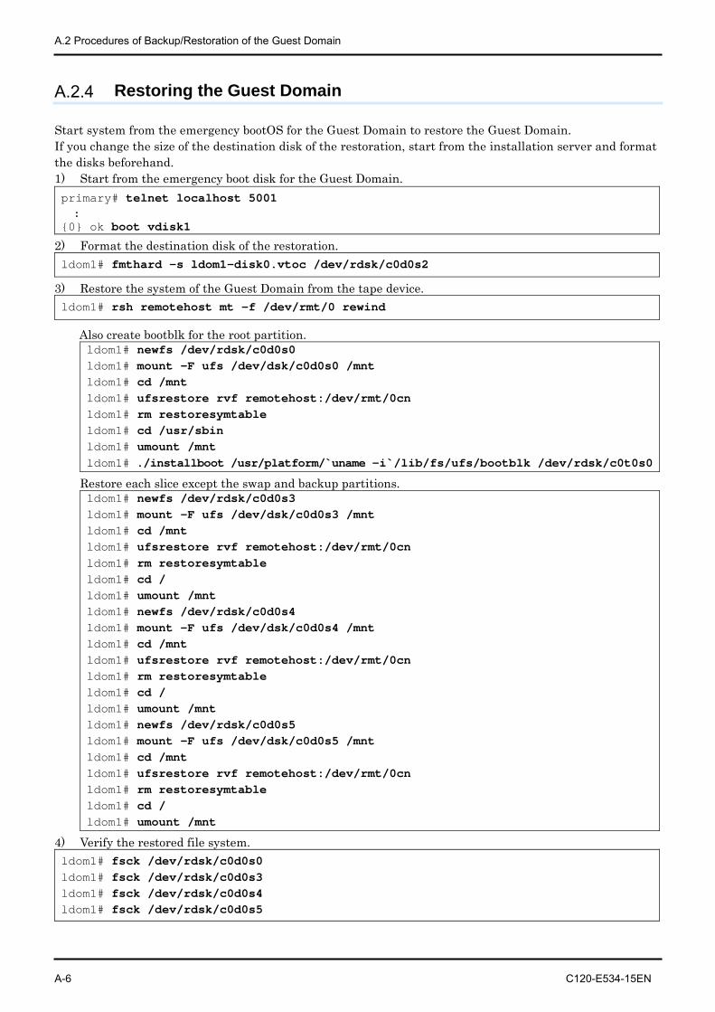
A.2 Procedures of Backup/Restoration of the Guest Domain
A-6 C120-E534-15EN
A.2.4 Restoring the Guest Domain
Start system from the emergency bootOS for the Guest Domain to restore the Guest Domain. If you change the size of the destination disk of the restoration, start from the installation server and format the disks beforehand. 1) Start from the emergency boot disk for the Guest Domain. primary# telnet localhost 5001 : {0} ok boot vdisk1
2) Format the destination disk of the restoration. ldom1# fmthard -s ldom1-disk0.vtoc /dev/rdsk/c0d0s2
3) Restore the system of the Guest Domain from the tape device. ldom1# rsh remotehost mt -f /dev/rmt/0 rewind
Also create bootblk for the root partition. ldom1# newfs /dev/rdsk/c0d0s0 ldom1# mount -F ufs /dev/dsk/c0d0s0 /mnt ldom1# cd /mnt ldom1# ufsrestore rvf remotehost:/dev/rmt/0cn ldom1# rm restoresymtable ldom1# cd /usr/sbin ldom1# umount /mnt ldom1# ./installboot /usr/platform/`uname -i`/lib/fs/ufs/bootblk /dev/rdsk/c0t0s0
Restore each slice except the swap and backup partitions. ldom1# newfs /dev/rdsk/c0d0s3 ldom1# mount -F ufs /dev/dsk/c0d0s3 /mnt ldom1# cd /mnt ldom1# ufsrestore rvf remotehost:/dev/rmt/0cn ldom1# rm restoresymtable ldom1# cd / ldom1# umount /mnt ldom1# newfs /dev/rdsk/c0d0s4 ldom1# mount -F ufs /dev/dsk/c0d0s4 /mnt ldom1# cd /mnt ldom1# ufsrestore rvf remotehost:/dev/rmt/0cn ldom1# rm restoresymtable ldom1# cd / ldom1# umount /mnt ldom1# newfs /dev/rdsk/c0d0s5 ldom1# mount -F ufs /dev/dsk/c0d0s5 /mnt ldom1# cd /mnt ldom1# ufsrestore rvf remotehost:/dev/rmt/0cn ldom1# rm restoresymtable ldom1# cd / ldom1# umount /mnt
4) Verify the restored file system. ldom1# fsck /dev/rdsk/c0d0s0 ldom1# fsck /dev/rdsk/c0d0s3 ldom1# fsck /dev/rdsk/c0d0s4 ldom1# fsck /dev/rdsk/c0d0s5
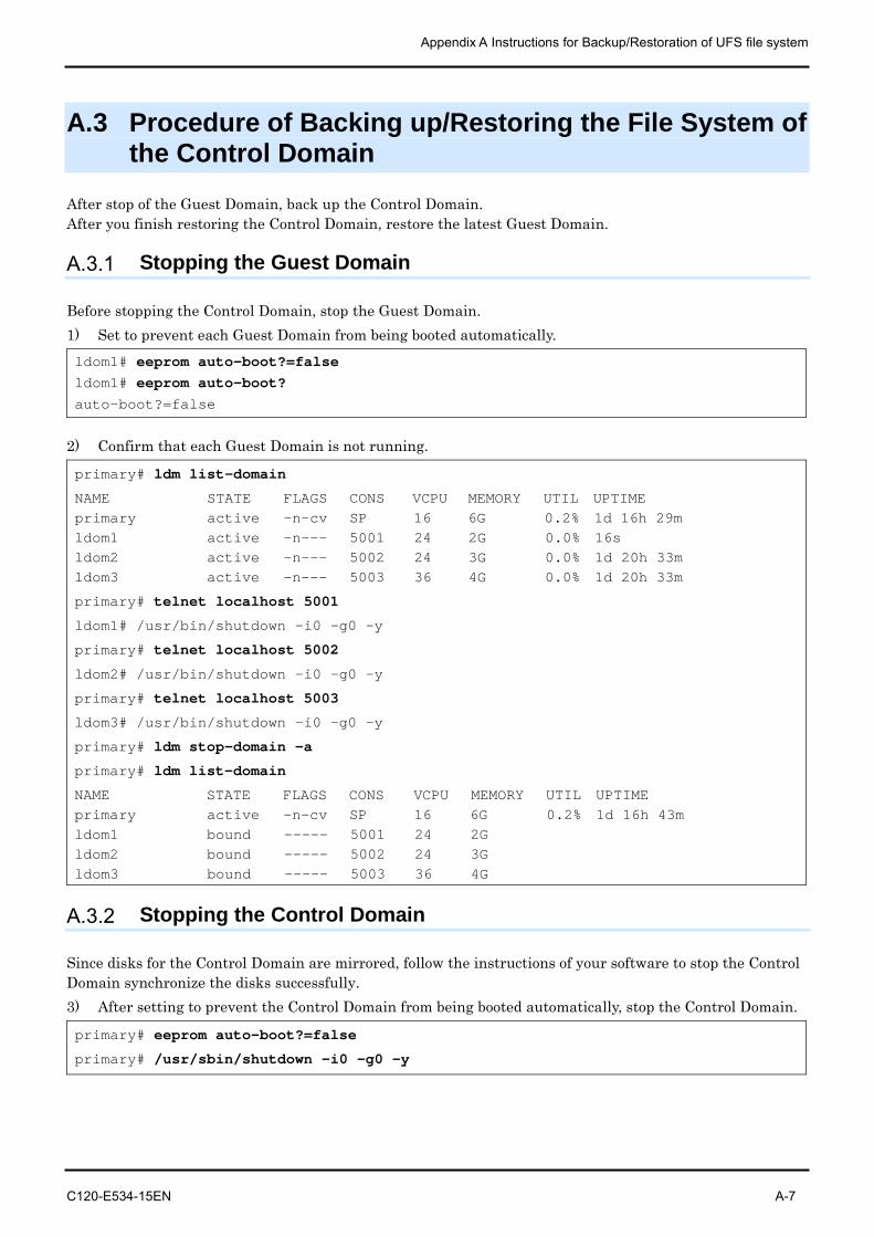
Appendix A Instructions for Backup/Restoration of UFS file system
C120-E534-15EN A-7
A.3 Procedure of Backing up/Restoring the File System of the Control Domain
After stop of the Guest Domain, back up the Control Domain. After you finish restoring the Control Domain, restore the latest Guest Domain.
A.3.1 Stopping the Guest Domain
Before stopping the Control Domain, stop the Guest Domain. 1) Set to prevent each Guest Domain from being booted automatically. ldom1# eeprom auto-boot?=false ldom1# eeprom auto-boot? auto-boot?=false
2) Confirm that each Guest Domain is not running.
primary# ldm list-domain
NAME STATE FLAGS CONS VCPU MEMORY UTIL UPTIME primary active -n-cv SP 16 6G 0.2% 1d 16h 29m ldom1 active -n--- 5001 24 2G 0.0% 16s ldom2 active -n--- 5002 24 3G 0.0% 1d 20h 33m ldom3 active -n--- 5003 36 4G 0.0% 1d 20h 33m
primary# telnet localhost 5001
ldom1# /usr/bin/shutdown -i0 -g0 –y
primary# telnet localhost 5002
ldom2# /usr/bin/shutdown -i0 -g0 –y
primary# telnet localhost 5003
ldom3# /usr/bin/shutdown -i0 -g0 –y
primary# ldm stop-domain –a
primary# ldm list-domain
NAME STATE FLAGS CONS VCPU MEMORY UTIL UPTIME primary active -n-cv SP 16 6G 0.2% 1d 16h 43m ldom1 bound ----- 5001 24 2G ldom2 bound ----- 5002 24 3G ldom3 bound ----- 5003 36 4G
A.3.2 Stopping the Control Domain
Since disks for the Control Domain are mirrored, follow the instructions of your software to stop the Control Domain synchronize the disks successfully. 3) After setting to prevent the Control Domain from being booted automatically, stop the Control Domain.
primary# eeprom auto-boot?=false
primary# /usr/sbin/shutdown -i0 -g0 -y
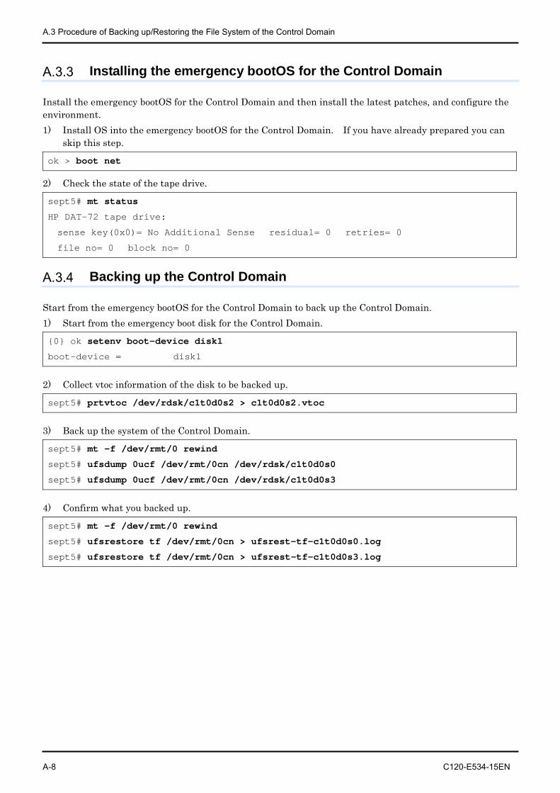
A.3 Procedure of Backing up/Restoring the File System of the Control Domain
A-8 C120-E534-15EN
A.3.3 Installing the emergency bootOS for the Control Domain
Install the emergency bootOS for the Control Domain and then install the latest patches, and configure the environment. 1) Install OS into the emergency bootOS for the Control Domain. If you have already prepared you can
skip this step.
ok > boot net
2) Check the state of the tape drive.
sept5# mt status
HP DAT-72 tape drive:
sense key(0x0)= No Additional Sense residual= 0 retries= 0
file no= 0 block no= 0
A.3.4 Backing up the Control Domain
Start from the emergency bootOS for the Control Domain to back up the Control Domain. 1) Start from the emergency boot disk for the Control Domain.
{0} ok setenv boot-device disk1
boot-device = disk1
2) Collect vtoc information of the disk to be backed up.
sept5# prtvtoc /dev/rdsk/c1t0d0s2 > c1t0d0s2.vtoc
3) Back up the system of the Control Domain.
sept5# mt -f /dev/rmt/0 rewind
sept5# ufsdump 0ucf /dev/rmt/0cn /dev/rdsk/c1t0d0s0
sept5# ufsdump 0ucf /dev/rmt/0cn /dev/rdsk/c1t0d0s3
4) Confirm what you backed up.
sept5# mt -f /dev/rmt/0 rewind
sept5# ufsrestore tf /dev/rmt/0cn > ufsrest-tf-c1t0d0s0.log
sept5# ufsrestore tf /dev/rmt/0cn > ufsrest-tf-c1t0d0s3.log
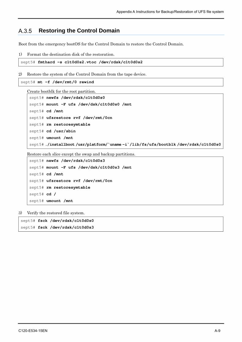
Appendix A Instructions for Backup/Restoration of UFS file system
C120-E534-15EN A-9
A.3.5 Restoring the Control Domain
Boot from the emergency bootOS for the Control Domain to restore the Control Domain.
1) Format the destination disk of the restoration.
sept5# fmthard -s c1t0d0s2.vtoc /dev/rdsk/c1t0d0s2
2) Restore the system of the Control Domain from the tape device.
sept5# mt -f /dev/rmt/0 rewind
Create bootblk for the root partition. sept5# newfs /dev/rdsk/c1t0d0s0
sept5# mount -F ufs /dev/dsk/c1t0d0s0 /mnt
sept5# cd /mnt
sept5# ufsrestore rvf /dev/rmt/0cn
sept5# rm restoresymtable
sept5# cd /usr/sbin
sept5# umount /mnt
sept5# ./installboot /usr/platform/`uname -i`/lib/fs/ufs/bootblk /dev/rdsk/c1t0d0s0
Restore each slice except the swap and backup partitions. sept5# newfs /dev/rdsk/c1t0d0s3
sept5# mount -F ufs /dev/dsk/c1t0d0s3 /mnt
sept5# cd /mnt
sept5# ufsrestore rvf /dev/rmt/0cn
sept5# rm restoresymtable
sept5# cd /
sept5# umount /mnt
3) Verify the restored file system.
sept5# fsck /dev/rdsk/c1t0d0s0
sept5# fsck /dev/rdsk/c1t0d0s3
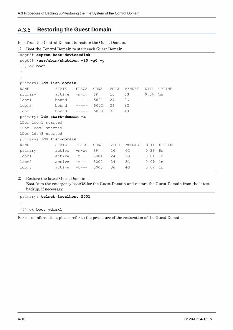
A.3 Procedure of Backing up/Restoring the File System of the Control Domain
A-10 C120-E534-15EN
A.3.6 Restoring the Guest Domain
Boot from the Control Domain to restore the Guest Domain. 1) Boot the Control Domain to start each Guest Domain. sept5# eeprom boot-device=disk sept5# /usr/sbin/shutdown -i0 -g0 –y {0} ok boot :
: primary# ldm list-domain NAME STATE FLAGS CONS VCPU MEMORY UTIL UPTIME
primary active -n-cv SP 16 6G 0.0% 5m
ldom1 bound ----- 5001 24 2G
ldom2 bound ----- 5002 24 3G
ldom3 bound ----- 5003 36 4G primary# ldm start-domain –a LDom ldom1 started
LDom ldom2 started
LDom ldom3 started primary# ldm list-domain NAME STATE FLAGS CONS VCPU MEMORY UTIL UPTIME
primary active -n-cv SP 16 6G 0.2% 8m
ldom1 active -t--- 5001 24 2G 0.0% 1m
ldom2 active -t--- 5002 24 3G 0.0% 1m
ldom3 active -t--- 5003 36 4G 0.0% 1m
2) Restore the latest Guest Domain. Boot from the emergency bootOS for the Guest Domain and restore the Guest Domain from the latest backup, if necessary.
primary# telnet localhost 5001
:
{0} ok boot vdisk1
For more information, please refer to the procedure of the restoration of the Guest Domain.
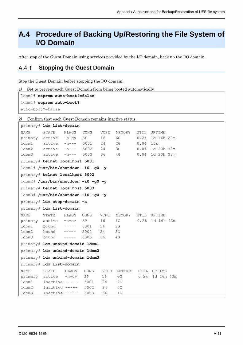
Appendix A Instructions for Backup/Restoration of UFS file system
C120-E534-15EN A-11
A.4 Procedure of Backing Up/Restoring the File System of I/O Domain
After stop of the Guest Domain using services provided by the I/O domain, back up the I/O domain.
A.4.1 Stopping the Guest Domain
Stop the Guest Domain before stopping the I/O domain.
1) Set to prevent each Guest Domain from being booted automatically. ldom1# eeprom auto-boot?=false
ldom1# eeprom auto-boot?
auto-boot?=false
2) Confirm that each Guest Domain remains inactive status. primary# ldm list-domain
NAME STATE FLAGS CONS VCPU MEMORY UTIL UPTIME primary active -n-cv SP 16 6G 0.2% 1d 16h 29m ldom1 active -n--- 5001 24 2G 0.0% 16s ldom2 active -n--- 5002 24 3G 0.0% 1d 20h 33m ldom3 active -n--- 5003 36 4G 0.0% 1d 20h 33m
primary# telnet localhost 5001
ldom1# /usr/bin/shutdown -i0 -g0 -y
primary# telnet localhost 5002
ldom2# /usr/bin/shutdown -i0 -g0 -y
primary# telnet localhost 5003
ldom3# /usr/bin/shutdown -i0 -g0 -y
primary# ldm stop-domain -a
primary# ldm list-domain
NAME STATE FLAGS CONS VCPU MEMORY UTIL UPTIME primary active -n-cv SP 16 6G 0.2% 1d 16h 43m ldom1 bound ----- 5001 24 2G ldom2 bound ----- 5002 24 3G ldom3 bound ----- 5003 36 4G
primary# ldm unbind-domain ldom1
primary# ldm unbind-domain ldom2
primary# ldm unbind-domain ldom3
primary# ldm list-domain
NAME STATE FLAGS CONS VCPU MEMORY UTIL UPTIME primary active -n-cv SP 16 6G 0.2% 1d 16h 43m ldom1 inactive ----- 5001 24 2G ldom2 inactive ----- 5002 24 3G ldom3 inactive ----- 5003 36 4G
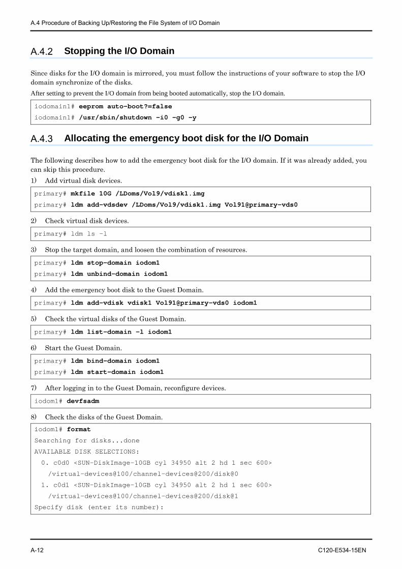
A.4 Procedure of Backing Up/Restoring the File System of I/O Domain
A-12 C120-E534-15EN
A.4.2 Stopping the I/O Domain
Since disks for the I/O domain is mirrored, you must follow the instructions of your software to stop the I/O domain synchronize of the disks. After setting to prevent the I/O domain from being booted automatically, stop the I/O domain.
iodomain1# eeprom auto-boot?=false
iodomain1# /usr/sbin/shutdown -i0 -g0 -y
A.4.3 Allocating the emergency boot disk for the I/O Domain
The following describes how to add the emergency boot disk for the I/O domain. If it was already added, you can skip this procedure. 1) Add virtual disk devices.
primary# mkfile 10G /LDoms/Vol9/vdisk1.img
primary# ldm add-vdsdev /LDoms/Vol9/vdisk1.img Vol91@primary-vds0
2) Check virtual disk devices.
primary# ldm ls -l
3) Stop the target domain, and loosen the combination of resources.
primary# ldm stop-domain iodom1
primary# ldm unbind-domain iodom1
4) Add the emergency boot disk to the Guest Domain.
primary# ldm add-vdisk vdisk1 Vol91@primary-vds0 iodom1
5) Check the virtual disks of the Guest Domain.
primary# ldm list-domain -l iodom1
6) Start the Guest Domain.
primary# ldm bind-domain iodom1
primary# ldm start-domain iodom1
7) After logging in to the Guest Domain, reconfigure devices.
iodom1# devfsadm
8) Check the disks of the Guest Domain. iodom1# format
Searching for disks...done
AVAILABLE DISK SELECTIONS:
0. c0d0 <SUN-DiskImage-10GB cyl 34950 alt 2 hd 1 sec 600>
/virtual-devices@100/channel-devices@200/disk@0
1. c0d1 <SUN-DiskImage-10GB cyl 34950 alt 2 hd 1 sec 600>
/virtual-devices@100/channel-devices@200/disk@1
Specify disk (enter its number):
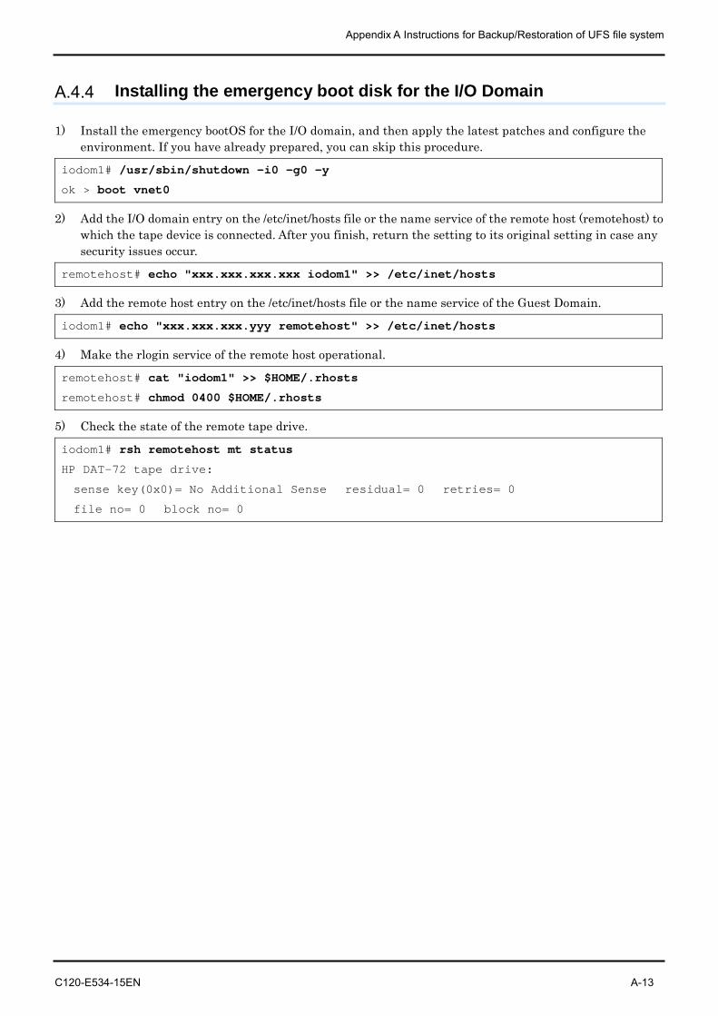
Appendix A Instructions for Backup/Restoration of UFS file system
C120-E534-15EN A-13
A.4.4 Installing the emergency boot disk for the I/O Domain
1) Install the emergency bootOS for the I/O domain, and then apply the latest patches and configure the environment. If you have already prepared, you can skip this procedure.
iodom1# /usr/sbin/shutdown -i0 -g0 –y
ok > boot vnet0
2) Add the I/O domain entry on the /etc/inet/hosts file or the name service of the remote host (remotehost) to which the tape device is connected. After you finish, return the setting to its original setting in case any security issues occur.
remotehost# echo "xxx.xxx.xxx.xxx iodom1" >> /etc/inet/hosts
3) Add the remote host entry on the /etc/inet/hosts file or the name service of the Guest Domain.
iodom1# echo "xxx.xxx.xxx.yyy remotehost" >> /etc/inet/hosts
4) Make the rlogin service of the remote host operational.
remotehost# cat "iodom1" >> $HOME/.rhosts
remotehost# chmod 0400 $HOME/.rhosts
5) Check the state of the remote tape drive.
iodom1# rsh remotehost mt status
HP DAT-72 tape drive:
sense key(0x0)= No Additional Sense residual= 0 retries= 0
file no= 0 block no= 0
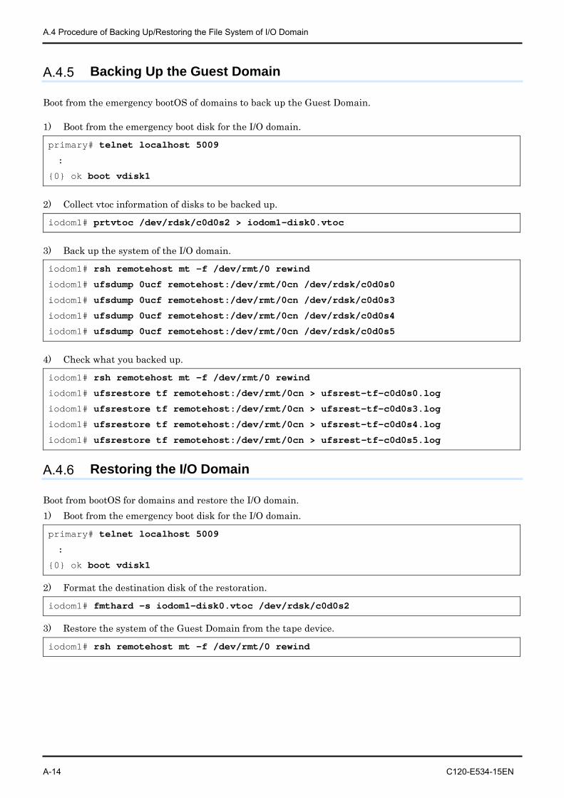
A.4 Procedure of Backing Up/Restoring the File System of I/O Domain
A-14 C120-E534-15EN
A.4.5 Backing Up the Guest Domain
Boot from the emergency bootOS of domains to back up the Guest Domain.
1) Boot from the emergency boot disk for the I/O domain.
primary# telnet localhost 5009
:
{0} ok boot vdisk1
2) Collect vtoc information of disks to be backed up.
iodom1# prtvtoc /dev/rdsk/c0d0s2 > iodom1-disk0.vtoc
3) Back up the system of the I/O domain.
iodom1# rsh remotehost mt -f /dev/rmt/0 rewind
iodom1# ufsdump 0ucf remotehost:/dev/rmt/0cn /dev/rdsk/c0d0s0
iodom1# ufsdump 0ucf remotehost:/dev/rmt/0cn /dev/rdsk/c0d0s3
iodom1# ufsdump 0ucf remotehost:/dev/rmt/0cn /dev/rdsk/c0d0s4
iodom1# ufsdump 0ucf remotehost:/dev/rmt/0cn /dev/rdsk/c0d0s5
4) Check what you backed up.
iodom1# rsh remotehost mt -f /dev/rmt/0 rewind
iodom1# ufsrestore tf remotehost:/dev/rmt/0cn > ufsrest-tf-c0d0s0.log
iodom1# ufsrestore tf remotehost:/dev/rmt/0cn > ufsrest-tf-c0d0s3.log
iodom1# ufsrestore tf remotehost:/dev/rmt/0cn > ufsrest-tf-c0d0s4.log
iodom1# ufsrestore tf remotehost:/dev/rmt/0cn > ufsrest-tf-c0d0s5.log
A.4.6 Restoring the I/O Domain
Boot from bootOS for domains and restore the I/O domain. 1) Boot from the emergency boot disk for the I/O domain.
primary# telnet localhost 5009
:
{0} ok boot vdisk1
2) Format the destination disk of the restoration.
iodom1# fmthard -s iodom1-disk0.vtoc /dev/rdsk/c0d0s2
3) Restore the system of the Guest Domain from the tape device.
iodom1# rsh remotehost mt -f /dev/rmt/0 rewind
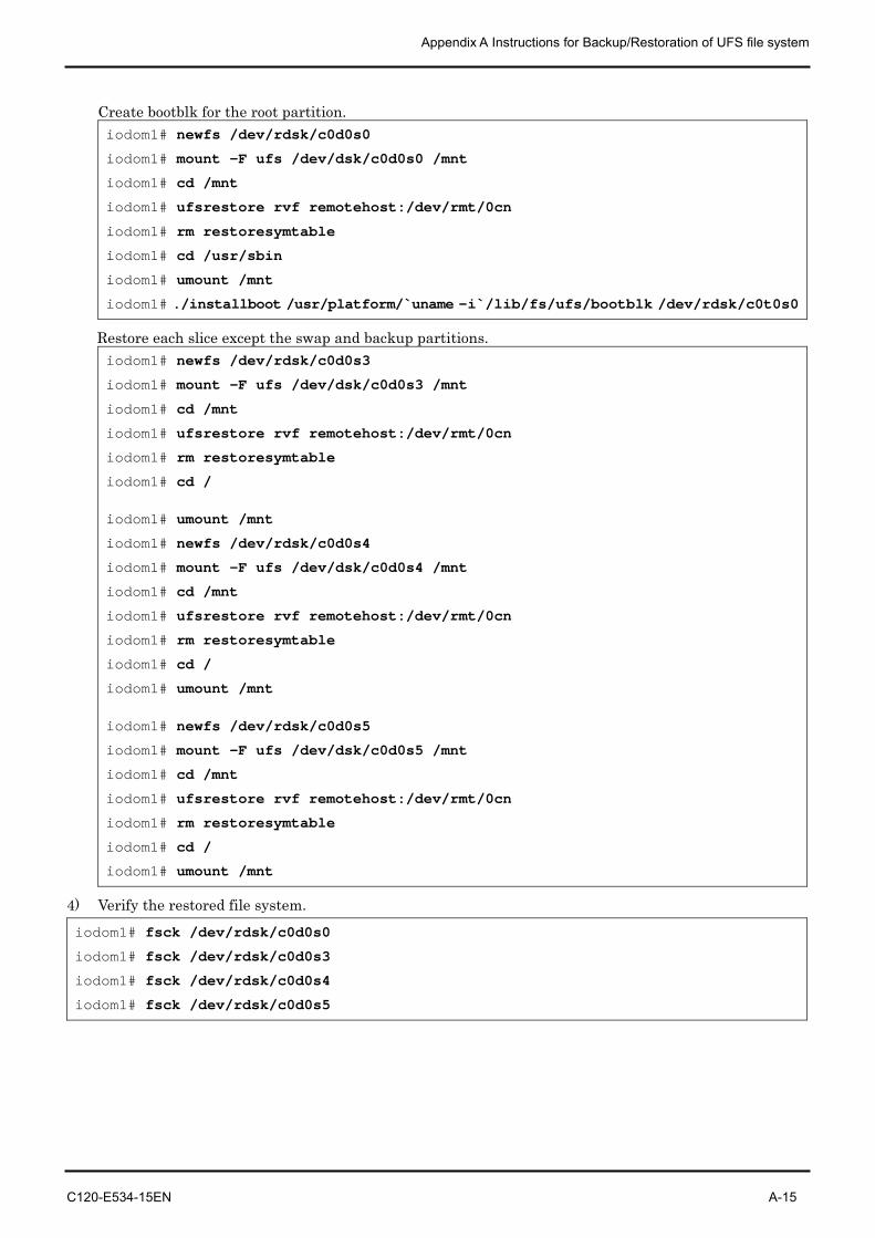
Appendix A Instructions for Backup/Restoration of UFS file system
C120-E534-15EN A-15
Create bootblk for the root partition. iodom1# newfs /dev/rdsk/c0d0s0
iodom1# mount -F ufs /dev/dsk/c0d0s0 /mnt
iodom1# cd /mnt
iodom1# ufsrestore rvf remotehost:/dev/rmt/0cn
iodom1# rm restoresymtable
iodom1# cd /usr/sbin
iodom1# umount /mnt
iodom1# ./installboot /usr/platform/`uname -i`/lib/fs/ufs/bootblk /dev/rdsk/c0t0s0
Restore each slice except the swap and backup partitions. iodom1# newfs /dev/rdsk/c0d0s3
iodom1# mount -F ufs /dev/dsk/c0d0s3 /mnt
iodom1# cd /mnt
iodom1# ufsrestore rvf remotehost:/dev/rmt/0cn
iodom1# rm restoresymtable
iodom1# cd /
iodom1# umount /mnt
iodom1# newfs /dev/rdsk/c0d0s4
iodom1# mount -F ufs /dev/dsk/c0d0s4 /mnt
iodom1# cd /mnt
iodom1# ufsrestore rvf remotehost:/dev/rmt/0cn
iodom1# rm restoresymtable
iodom1# cd /
iodom1# umount /mnt
iodom1# newfs /dev/rdsk/c0d0s5
iodom1# mount -F ufs /dev/dsk/c0d0s5 /mnt
iodom1# cd /mnt
iodom1# ufsrestore rvf remotehost:/dev/rmt/0cn
iodom1# rm restoresymtable
iodom1# cd /
iodom1# umount /mnt
4) Verify the restored file system.
iodom1# fsck /dev/rdsk/c0d0s0
iodom1# fsck /dev/rdsk/c0d0s3
iodom1# fsck /dev/rdsk/c0d0s4
iodom1# fsck /dev/rdsk/c0d0s5
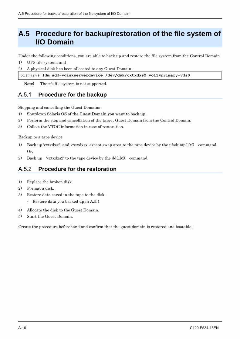
A.5 Procedure for backup/restoration of the file system of I/O Domain
A-16 C120-E534-15EN
A.5 Procedure for backup/restoration of the file system of I/O Domain
Under the following conditions, you are able to back up and restore the file system from the Control Domain 1) UFS file system, and 2) A physical disk has been allocated to any Guest Domain. primary# ldm add-vdiskserverdevice /dev/dsk/cxtxdxs2 vol1@primary-vds0
Note) The zfs file system is not supported.
A.5.1 Procedure for the backup
Stopping and cancelling the Guest Domains 1) Shutdown Solaris OS of the Guest Domain you want to back up. 2) Perform the stop and cancellation of the target Guest Domain from the Control Domain. 3) Collect the VTOC information in case of restoration.
Backup to a tape device
1) Back up 'cxtxdxs2' and 'cxtxdxsx' except swap area to the tape device by the ufsdump(1M) command. Or,
2) Back up 'cxtxdxs2' to the tape device by the dd(1M) command.
A.5.2 Procedure for the restoration
1) Replace the broken disk. 2) Format a disk. 3) Restore data saved in the tape to the disk.
- Restore data you backed up in A.5.1
4) Allocate the disk to the Guest Domain. 5) Start the Guest Domain.
Create the procedure beforehand and confirm that the guest domain is restored and bootable.
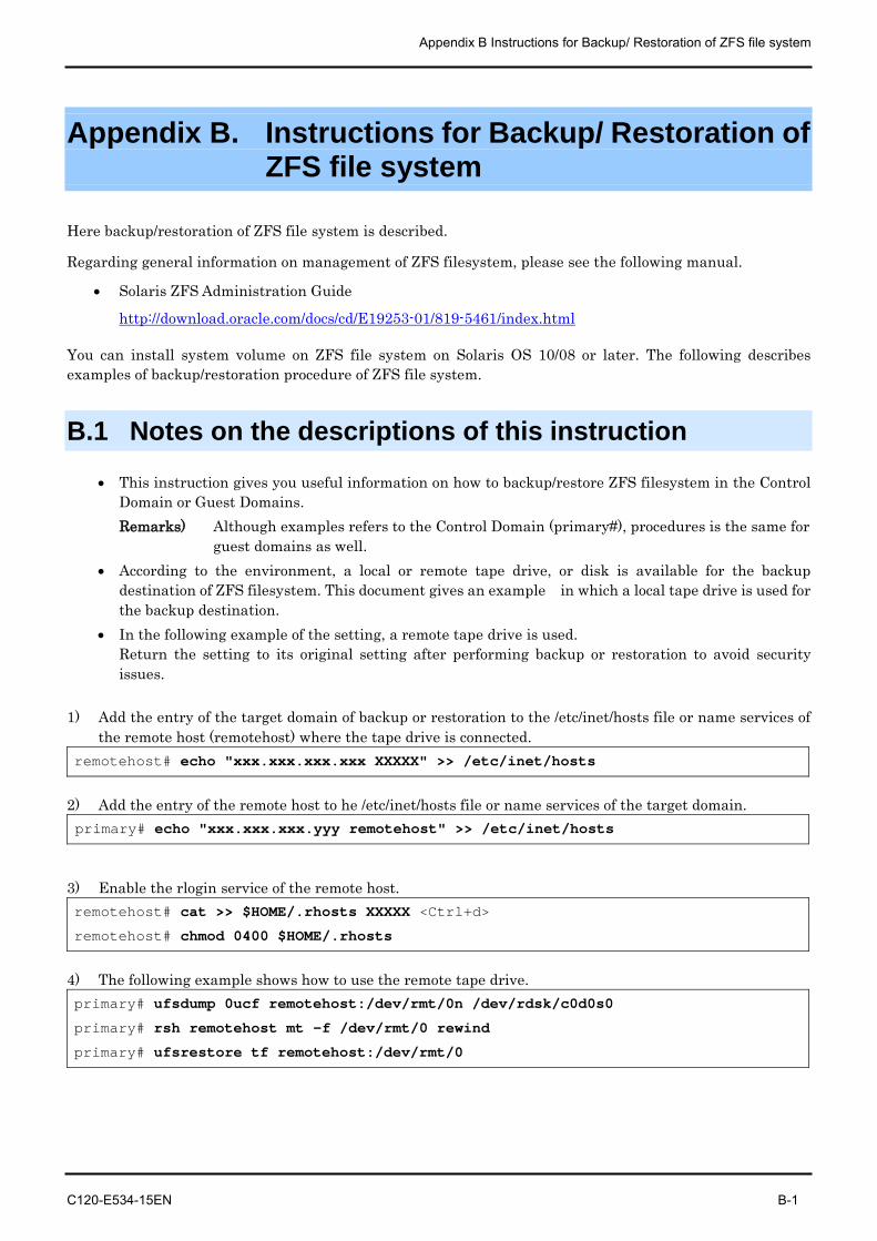
Appendix B Instructions for Backup/ Restoration of ZFS file system
C120-E534-15EN B-1
Appendix B. Instructions for Backup/ Restoration of ZFS file system
Here backup/restoration of ZFS file system is described.
Regarding general information on management of ZFS filesystem, please see the following manual.
• Solaris ZFS Administration Guide
http://download.oracle.com/docs/cd/E19253-01/819-5461/index.html
You can install system volume on ZFS file system on Solaris OS 10/08 or later. The following describes examples of backup/restoration procedure of ZFS file system.
B.1 Notes on the descriptions of this instruction
• This instruction gives you useful information on how to backup/restore ZFS filesystem in the Control Domain or Guest Domains. Remarks) Although examples refers to the Control Domain (primary#), procedures is the same for
guest domains as well. • According to the environment, a local or remote tape drive, or disk is available for the backup
destination of ZFS filesystem. This document gives an example in which a local tape drive is used for the backup destination.
• In the following example of the setting, a remote tape drive is used. Return the setting to its original setting after performing backup or restoration to avoid security issues.
1) Add the entry of the target domain of backup or restoration to the /etc/inet/hosts file or name services of
the remote host (remotehost) where the tape drive is connected. remotehost# echo "xxx.xxx.xxx.xxx XXXXX" >> /etc/inet/hosts
2) Add the entry of the remote host to he /etc/inet/hosts file or name services of the target domain. primary# echo "xxx.xxx.xxx.yyy remotehost" >> /etc/inet/hosts
3) Enable the rlogin service of the remote host. remotehost# cat >> $HOME/.rhosts XXXXX <Ctrl+d>
remotehost# chmod 0400 $HOME/.rhosts
4) The following example shows how to use the remote tape drive. primary# ufsdump 0ucf remotehost:/dev/rmt/0n /dev/rdsk/c0d0s0
primary# rsh remotehost mt -f /dev/rmt/0 rewind
primary# ufsrestore tf remotehost:/dev/rmt/0
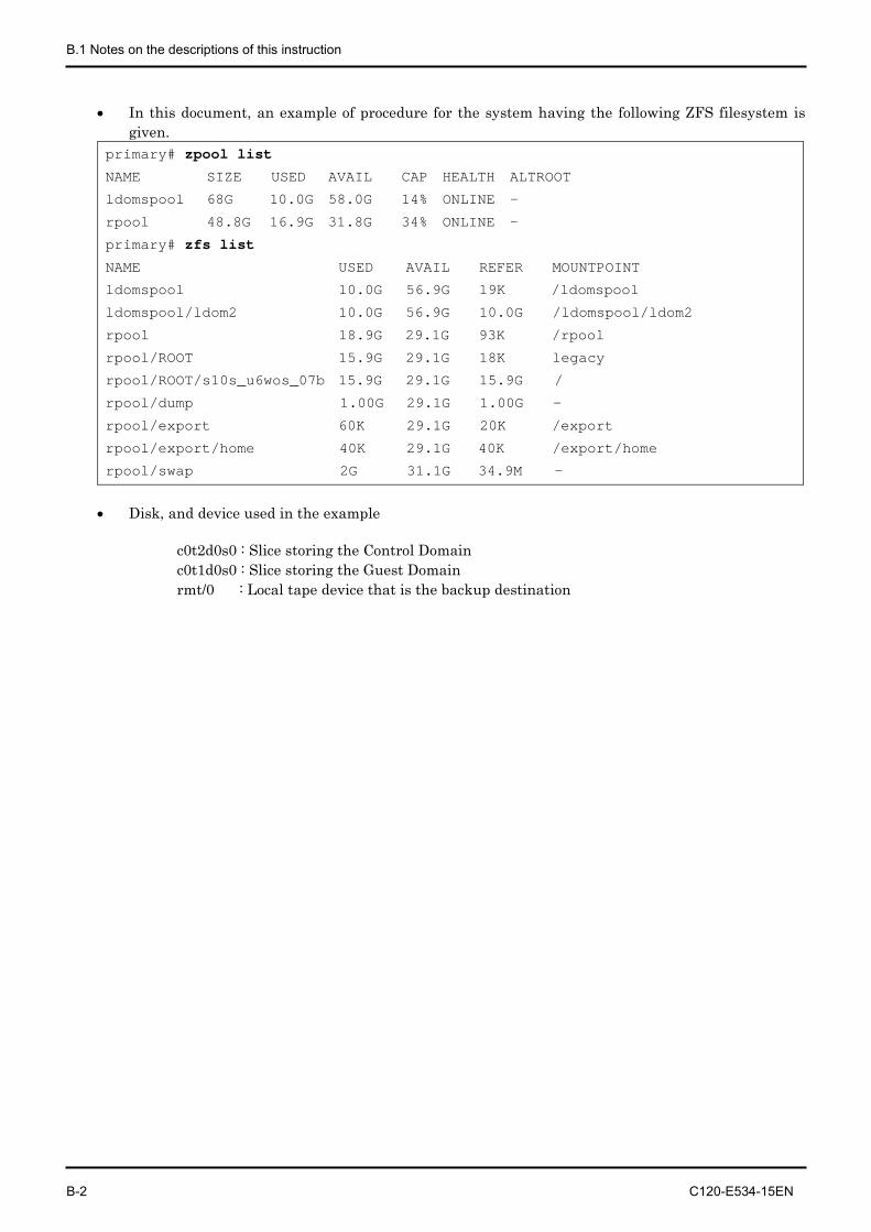
B.1 Notes on the descriptions of this instruction
B-2 C120-E534-15EN
• In this document, an example of procedure for the system having the following ZFS filesystem is given.
primary# zpool list
NAME SIZE USED AVAIL CAP HEALTH ALTROOT
ldomspool 68G 10.0G 58.0G 14% ONLINE -
rpool 48.8G 16.9G 31.8G 34% ONLINE -
primary# zfs list
NAME USED AVAIL REFER MOUNTPOINT
ldomspool 10.0G 56.9G 19K /ldomspool
ldomspool/ldom2 10.0G 56.9G 10.0G /ldomspool/ldom2
rpool 18.9G 29.1G 93K /rpool
rpool/ROOT 15.9G 29.1G 18K legacy
rpool/ROOT/s10s_u6wos_07b 15.9G 29.1G 15.9G /
rpool/dump 1.00G 29.1G 1.00G -
rpool/export 60K 29.1G 20K /export
rpool/export/home 40K 29.1G 40K /export/home
rpool/swap 2G 31.1G 34.9M -
• Disk, and device used in the example
c0t2d0s0 : Slice storing the Control Domain c0t1d0s0 : Slice storing the Guest Domain rmt/0 : Local tape device that is the backup destination
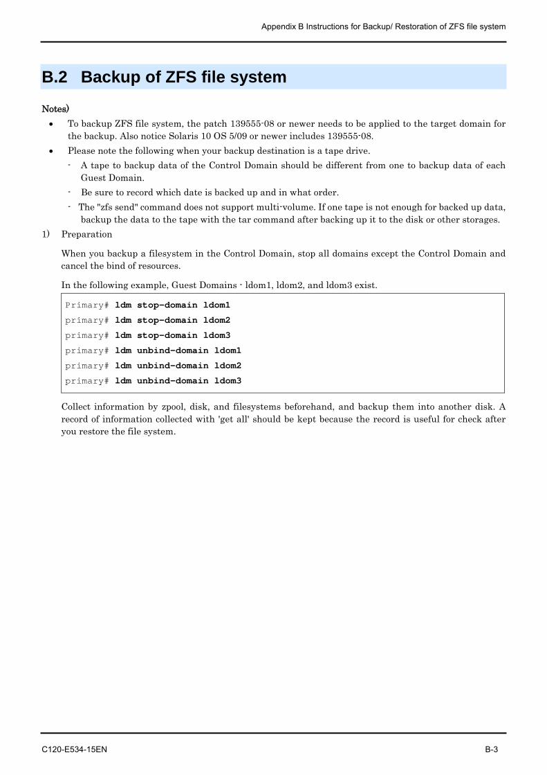
Appendix B Instructions for Backup/ Restoration of ZFS file system
C120-E534-15EN B-3
B.2 Backup of ZFS file system
Notes) • To backup ZFS file system, the patch 139555-08 or newer needs to be applied to the target domain for
the backup. Also notice Solaris 10 OS 5/09 or newer includes 139555-08. • Please note the following when your backup destination is a tape drive.
- A tape to backup data of the Control Domain should be different from one to backup data of each Guest Domain.
- Be sure to record which date is backed up and in what order. - The "zfs send" command does not support multi-volume. If one tape is not enough for backed up data,
backup the data to the tape with the tar command after backing up it to the disk or other storages. 1) Preparation
When you backup a filesystem in the Control Domain, stop all domains except the Control Domain and cancel the bind of resources.
In the following example, Guest Domains - ldom1, ldom2, and ldom3 exist.
Primary# ldm stop-domain ldom1
primary# ldm stop-domain ldom2
primary# ldm stop-domain ldom3
primary# ldm unbind-domain ldom1
primary# ldm unbind-domain ldom2
primary# ldm unbind-domain ldom3
Collect information by zpool, disk, and filesystems beforehand, and backup them into another disk. A record of information collected with 'get all' should be kept because the record is useful for check after you restore the file system.
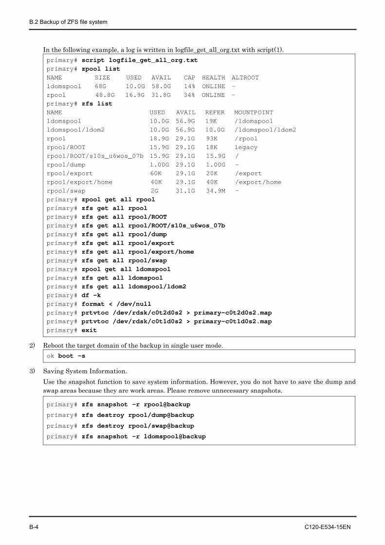
B.2 Backup of ZFS file system
B-4 C120-E534-15EN
In the following example, a log is written in logfile_get_all_org.txt with script(1). primary# script logfile_get_all_org.txt primary# zpool list NAME SIZE USED AVAIL CAP HEALTH ALTROOT ldomspool 68G 10.0G 58.0G 14% ONLINE - rpool 48.8G 16.9G 31.8G 34% ONLINE - primary# zfs list NAME USED AVAIL REFER MOUNTPOINT ldomspool 10.0G 56.9G 19K /ldomspool ldomspool/ldom2 10.0G 56.9G 10.0G /ldomspool/ldom2 rpool 18.9G 29.1G 93K /rpool rpool/ROOT 15.9G 29.1G 18K legacy rpool/ROOT/s10s_u6wos_07b 15.9G 29.1G 15.9G / rpool/dump 1.00G 29.1G 1.00G - rpool/export 60K 29.1G 20K /export rpool/export/home 40K 29.1G 40K /export/home rpool/swap 2G 31.1G 34.9M - primary# zpool get all rpool primary# zfs get all rpool primary# zfs get all rpool/ROOT primary# zfs get all rpool/ROOT/s10s_u6wos_07b primary# zfs get all rpool/dump primary# zfs get all rpool/export primary# zfs get all rpool/export/home primary# zfs get all rpool/swap primary# zpool get all ldomspool primary# zfs get all ldomspool primary# zfs get all ldomspool/ldom2 primary# df -k primary# format < /dev/null primary# prtvtoc /dev/rdsk/c0t2d0s2 > primary-c0t2d0s2.map primary# prtvtoc /dev/rdsk/c0t1d0s2 > primary-c0t1d0s2.map primary# exit
2) Reboot the target domain of the backup in single user mode. ok boot -s
3) Saving System Information. Use the snapshot function to save system information. However, you do not have to save the dump and swap areas because they are work areas. Please remove unnecessary snapshots.
primary# zfs snapshot -r rpool@backup
primary# zfs destroy rpool/dump@backup
primary# zfs destroy rpool/swap@backup
primary# zfs snapshot -r ldomspool@backup
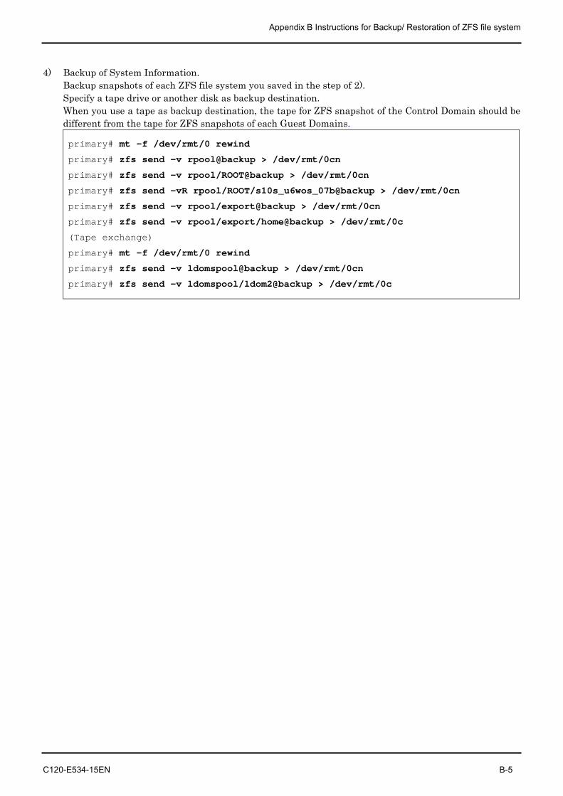
Appendix B Instructions for Backup/ Restoration of ZFS file system
C120-E534-15EN B-5
4) Backup of System Information. Backup snapshots of each ZFS file system you saved in the step of 2). Specify a tape drive or another disk as backup destination. When you use a tape as backup destination, the tape for ZFS snapshot of the Control Domain should be different from the tape for ZFS snapshots of each Guest Domains.
primary# mt -f /dev/rmt/0 rewind
primary# zfs send -v rpool@backup > /dev/rmt/0cn
primary# zfs send -v rpool/ROOT@backup > /dev/rmt/0cn
primary# zfs send -vR rpool/ROOT/s10s_u6wos_07b@backup > /dev/rmt/0cn
primary# zfs send -v rpool/export@backup > /dev/rmt/0cn
primary# zfs send -v rpool/export/home@backup > /dev/rmt/0c
(Tape exchange)
primary# mt -f /dev/rmt/0 rewind
primary# zfs send -v ldomspool@backup > /dev/rmt/0cn
primary# zfs send -v ldomspool/ldom2@backup > /dev/rmt/0c
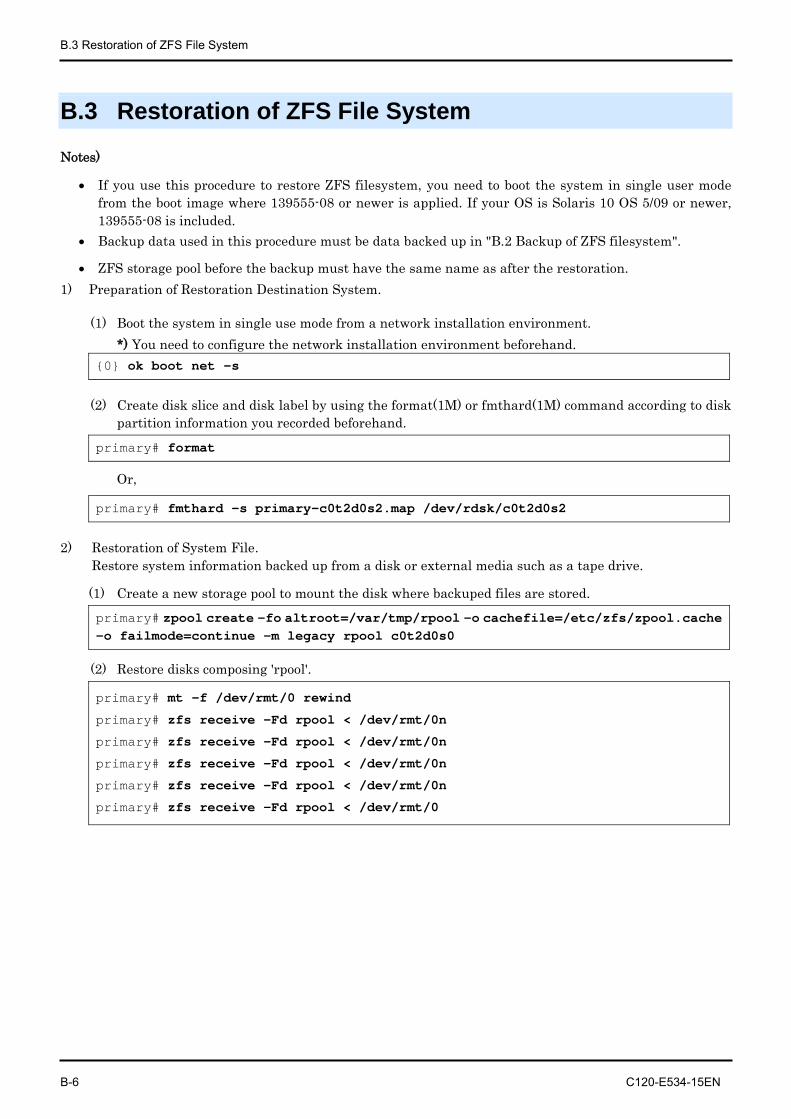
B.3 Restoration of ZFS File System
B-6 C120-E534-15EN
B.3 Restoration of ZFS File System
Notes)
• If you use this procedure to restore ZFS filesystem, you need to boot the system in single user mode from the boot image where 139555-08 or newer is applied. If your OS is Solaris 10 OS 5/09 or newer, 139555-08 is included.
• Backup data used in this procedure must be data backed up in "B.2 Backup of ZFS filesystem".
• ZFS storage pool before the backup must have the same name as after the restoration. 1) Preparation of Restoration Destination System.
(1) Boot the system in single use mode from a network installation environment. *) You need to configure the network installation environment beforehand.
{0} ok boot net -s
(2) Create disk slice and disk label by using the format(1M) or fmthard(1M) command according to disk partition information you recorded beforehand.
primary# format
Or,
primary# fmthard -s primary-c0t2d0s2.map /dev/rdsk/c0t2d0s2
2) Restoration of System File. Restore system information backed up from a disk or external media such as a tape drive.
(1) Create a new storage pool to mount the disk where backuped files are stored.
primary# zpool create -fo altroot=/var/tmp/rpool -o cachefile=/etc/zfs/zpool.cache -o failmode=continue -m legacy rpool c0t2d0s0
(2) Restore disks composing 'rpool'.
primary# mt -f /dev/rmt/0 rewind
primary# zfs receive -Fd rpool < /dev/rmt/0n
primary# zfs receive -Fd rpool < /dev/rmt/0n
primary# zfs receive -Fd rpool < /dev/rmt/0n
primary# zfs receive -Fd rpool < /dev/rmt/0n
primary# zfs receive -Fd rpool < /dev/rmt/0
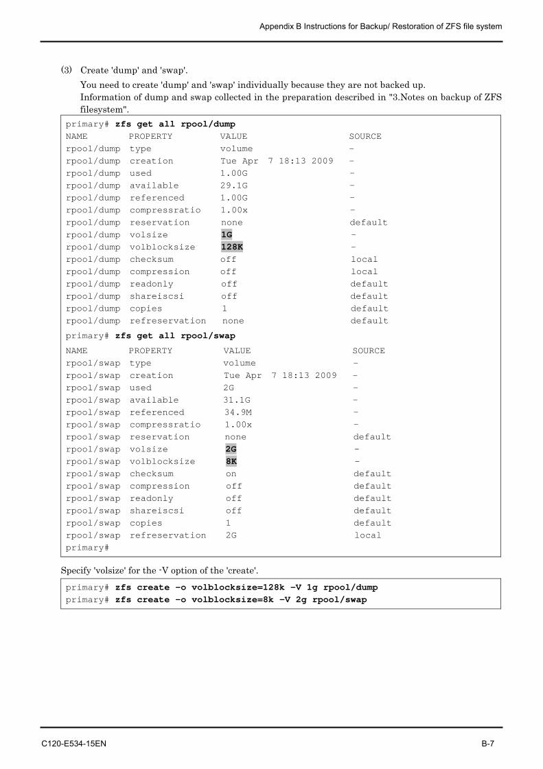
Appendix B Instructions for Backup/ Restoration of ZFS file system
C120-E534-15EN B-7
(3) Create 'dump' and 'swap'. You need to create 'dump' and 'swap' individually because they are not backed up. Information of dump and swap collected in the preparation described in "3.Notes on backup of ZFS filesystem".
primary# zfs get all rpool/dump NAME PROPERTY VALUE SOURCE rpool/dump type volume - rpool/dump creation Tue Apr 7 18:13 2009 - rpool/dump used 1.00G - rpool/dump available 29.1G - rpool/dump referenced 1.00G - rpool/dump compressratio 1.00x - rpool/dump reservation none default rpool/dump volsize 1G - rpool/dump volblocksize 128K - rpool/dump checksum off local rpool/dump compression off local rpool/dump readonly off default rpool/dump shareiscsi off default rpool/dump copies 1 default rpool/dump refreservation none default
primary# zfs get all rpool/swap
NAME PROPERTY VALUE SOURCE rpool/swap type volume - rpool/swap creation Tue Apr 7 18:13 2009 - rpool/swap used 2G - rpool/swap available 31.1G - rpool/swap referenced 34.9M - rpool/swap compressratio 1.00x - rpool/swap reservation none default rpool/swap volsize 2G - rpool/swap volblocksize 8K - rpool/swap checksum on default rpool/swap compression off default rpool/swap readonly off default rpool/swap shareiscsi off default rpool/swap copies 1 default rpool/swap refreservation 2G local primary#
Specify 'volsize' for the -V option of the 'create'.
primary# zfs create -o volblocksize=128k -V 1g rpool/dump primary# zfs create -o volblocksize=8k -V 2g rpool/swap
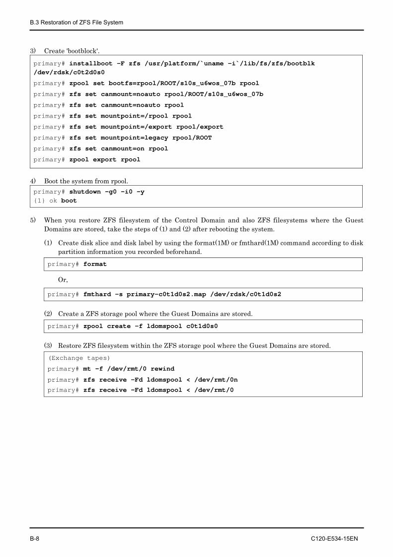
B.3 Restoration of ZFS File System
B-8 C120-E534-15EN
3) Create 'bootblock'.
primary# installboot -F zfs /usr/platform/`uname -i`/lib/fs/zfs/bootblk /dev/rdsk/c0t2d0s0
primary# zpool set bootfs=rpool/ROOT/s10s_u6wos_07b rpool
primary# zfs set canmount=noauto rpool/ROOT/s10s_u6wos_07b
primary# zfs set canmount=noauto rpool
primary# zfs set mountpoint=/rpool rpool
primary# zfs set mountpoint=/export rpool/export
primary# zfs set mountpoint=legacy rpool/ROOT
primary# zfs set canmount=on rpool
primary# zpool export rpool
4) Boot the system from rpool. primary# shutdown -g0 -i0 -y {1} ok boot
5) When you restore ZFS filesystem of the Control Domain and also ZFS filesystems where the Guest Domains are stored, take the steps of (1) and (2) after rebooting the system.
(1) Create disk slice and disk label by using the format(1M) or fmthard(1M) command according to disk partition information you recorded beforehand.
primary# format
Or,
primary# fmthard -s primary-c0t1d0s2.map /dev/rdsk/c0t1d0s2
(2) Create a ZFS storage pool where the Guest Domains are stored.
primary# zpool create -f ldomspool c0t1d0s0
(3) Restore ZFS filesystem within the ZFS storage pool where the Guest Domains are stored.
(Exchange tapes)
primary# mt -f /dev/rmt/0 rewind
primary# zfs receive -Fd ldomspool < /dev/rmt/0n
primary# zfs receive -Fd ldomspool < /dev/rmt/0
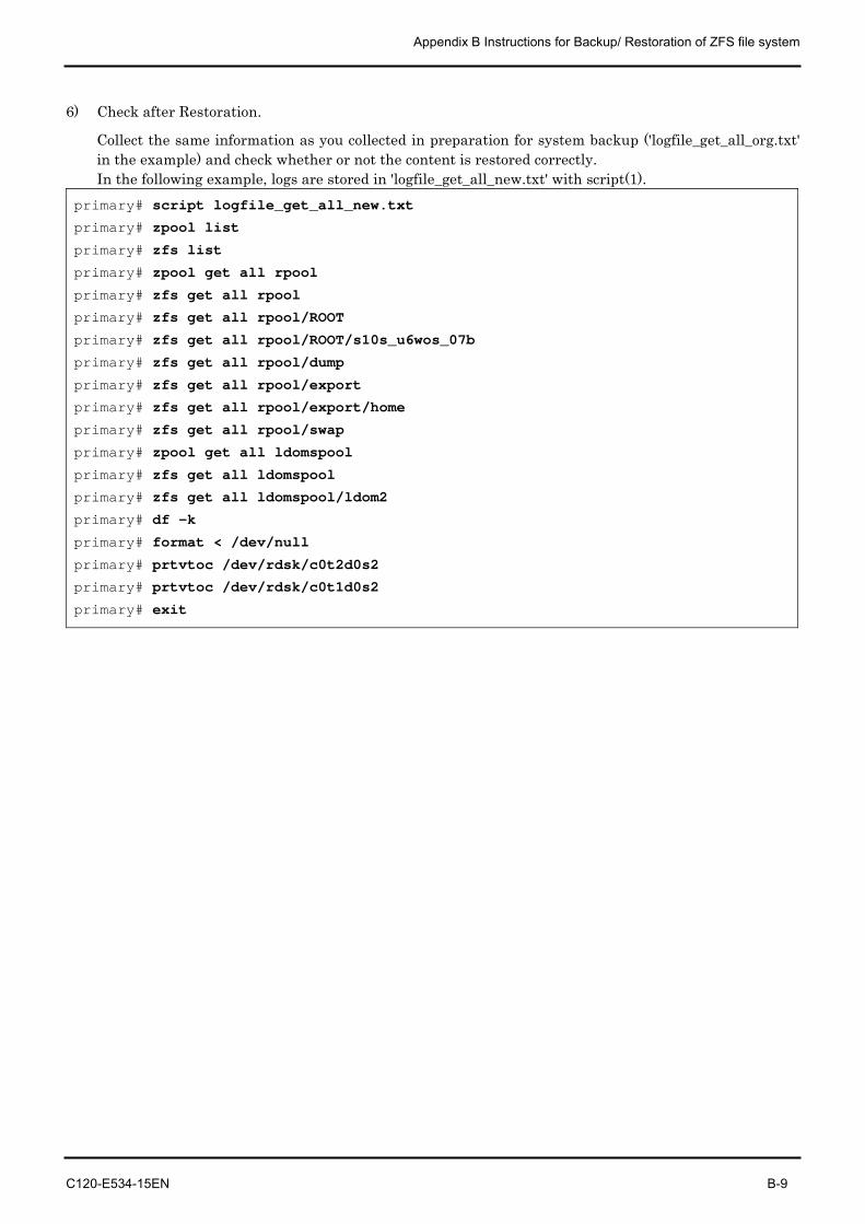
Appendix B Instructions for Backup/ Restoration of ZFS file system
C120-E534-15EN B-9
6) Check after Restoration.
Collect the same information as you collected in preparation for system backup ('logfile_get_all_org.txt' in the example) and check whether or not the content is restored correctly. In the following example, logs are stored in 'logfile_get_all_new.txt' with script(1).
primary# script logfile_get_all_new.txt
primary# zpool list
primary# zfs list
primary# zpool get all rpool
primary# zfs get all rpool
primary# zfs get all rpool/ROOT
primary# zfs get all rpool/ROOT/s10s_u6wos_07b
primary# zfs get all rpool/dump
primary# zfs get all rpool/export
primary# zfs get all rpool/export/home
primary# zfs get all rpool/swap
primary# zpool get all ldomspool
primary# zfs get all ldomspool
primary# zfs get all ldomspool/ldom2
primary# df -k
primary# format < /dev/null
primary# prtvtoc /dev/rdsk/c0t2d0s2
primary# prtvtoc /dev/rdsk/c0t1d0s2
primary# exit
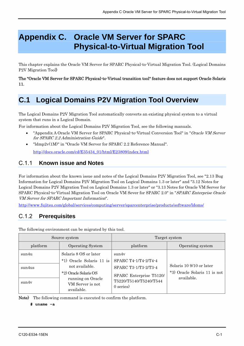
Appendix C Oracle VM Server for SPARC Physical-to-Virtual Migration Tool
C120-E534-15EN C-1
Appendix C. Oracle VM Server for SPARC Physical-to-Virtual Migration Tool
This chapter explains the Oracle VM Server for SPARC Physical-to-Virtual Migration Tool. (Logical Domains P2V Migration Tool)
The "Oracle VM Server for SPARC Physical-to-Virtual transition tool" feature does not support Oracle Solaris 11.
C.1 Logical Domains P2V Migration Tool Overview
The Logical Domains P2V Migration Tool automatically converts an existing physical system to a virtual system that runs in a Logical Domain. For information about the Logical Domains P2V Migration Tool, see the following manuals.
• "Appendix A Oracle VM Server for SPARC Physical-to-Virtual Conversion Tool" in "Oracle VM Server for SPARC 2.2 Administration Guide".
• "ldmp2v(1M)" in "Oracle VM Server for SPARC 2.2 Reference Manual".
http://docs.oracle.com/cd/E35434_01/html/E23809/index.html
C.1.1 Known issue and Notes
For information about the known issue and notes of the Logical Domains P2V Migration Tool, see "2.13 Bug Information for Logical Domains P2V Migration Tool on Logical Domains 1.3 or later" and "3.12 Notes for Logical Domains P2V Migration Tool on Logical Domains 1.3 or later" or "3.13 Notes for Oracle VM Server for SPARC Physical-to-Virtual Migration Tool on Oracle VM Sever for SPARC 2.0" in "SPARC Enterprise Oracle VM Server for SPARC Important Information". http://www.fujitsu.com/global/services/computing/server/sparcenterprise/products/software/ldoms/
C.1.2 Prerequisites
The following environment can be migrated by this tool.
Source system Target system
platform Operating System platform Operating system
sun4u Solaris 8 OS or later *1) Oracle Solaris 11 is
not available. *2) Oracle Solaris OS
running on Oracle VM Server is not available.
sun4v SPARC T4-1/T4-2/T4-4 SPARC T3-1/T3-2/T3-4
SPARC Enterprise T5120/ T5220/T5140/T5240/T5440 series)
Solaris 10 9/10 or later *3) Oracle Solaris 11 is not
available.
sun4us
sun4v
Note) The following command is executed to confirm the platform. # uname -a
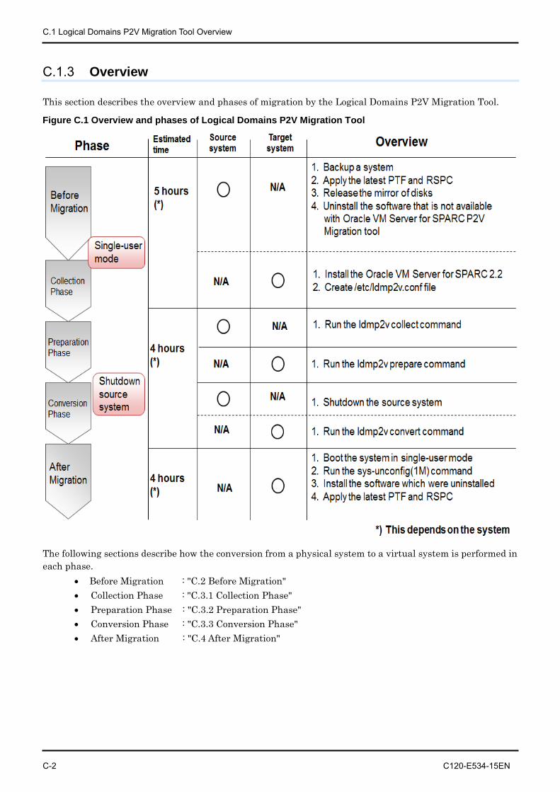
C.1 Logical Domains P2V Migration Tool Overview
C-2 C120-E534-15EN
C.1.3 Overview
This section describes the overview and phases of migration by the Logical Domains P2V Migration Tool.
Figure C.1 Overview and phases of Logical Domains P2V Migration Tool
The following sections describe how the conversion from a physical system to a virtual system is performed in each phase.
• Before Migration : "C.2 Before Migration" • Collection Phase : "C.3.1 Collection Phase" • Preparation Phase : "C.3.2 Preparation Phase" • Conversion Phase : "C.3.3 Conversion Phase" • After Migration : "C.4 After Migration"
Appendix C Oracle VM Server for SPARC Physical-to-Virtual Migration Tool
C120-E534-15EN C-3
C.2 Before Migration
This phase has the following procedures. [Source system]
• Backup a source system. • Apply the latest PTF and Recommended and Security Patches to avoid the problem of the Solaris
OS upgrade. • Please refer to Enhanced Support Facility Installation Guide and Enhanced Support Facility
User's Guide for the instructions on how to install Enhanced Support Facility (ESF). These manuals can be downloaded at the following URL. Remarks) If you search "Enhanced Support Facility" from the following URL, these manuals
will be displayed according to version number.
http://www.fujitsu.com/global/support/software/manual/
• Uninstall the software that is not available with Solaris 10 OS. • Uninstall the software that is not available with Logical Domains P2V Migration Tool. • Confirm the known issue and notes of the Logical Domains P2V Migration Tool.
"C.1.1 Known issue and Notes" [Target system]
• Install the Solaris 10 OS 9/10 or later • Confirm that the Logical Domains Manager of the target system is Oracle VM Server for SPARC
2.0 or Logical Domains 1.3 or later. If Logical Domains 1.2 or earlier, see "D.3 Removing the Logical Domains Manager" and "D.2 Installing Logical Domains Manager (Logical Domains 1.3)" or "7.13 How to Remove and Re-install the Logical Domains"
• Apply the latest PTF and Recommended and Security Patches. • Create the /etc/ldmp2v.conf file.
After installing the Logical Domains P2V Migration Tool, please refer to the following file and configure the properties in this file. /opt/SUNWldmp2v/etc/ldmp2v.conf.sample
Example)
target# cp /opt/SUNWldmp2v/etc/ldmp2v.conf.sample /etc/ldmp2v.conf
Note) For more information, see the ldmp2v.conf.sample configuration file that is part of the downloadable bundle.
C.3 Phase of the Logical Domains P2V Migration Tool
C-4 C120-E534-15EN
C.3 Phase of the Logical Domains P2V Migration Tool
The following sections describe how the conversion from a physical system to a virtual system is performed in each phase.
• Collection Phase • Preparation Phase • Conversion Phase
For information about the notes of each phase, see "C.1.1 Known issue and Notes".
C.3.1 Collection Phase
This phase creates a file system image (archive and manifest) of the source system (physical system). It is necessary to store this data where the target system can access. [Source system]
• Boot the system in single-user mode. • If necessary, copy the ldmp2v command to the source system
If the P2V tool is not installed in a directory that is shared between the source and target systems, you must copy the /usr/sbin/ldmp2v script to the source system.
• Run the "ldmp2v collect" command. ldmp2v(1M) command collects a source system's data and output to the <data-dir>.
source# ldmp2v collect -d <data-dir>
For more information about the command option, see manuals of Oracle Corporation listed in "C.1 Logical Domains P2V Migration Tool Overview".
[Target system] - None.
C.3.2 Preparation Phase
In this phase, "ldmp2v prepare" command creates the Guest Domain on the target system based on the configuration information collected in the collection phase. [Source system]
• None. [Target system]
• Run the "ldmp2v prepare" command on the Control Domain of the target system. target# ldmp2v prepare -d <data-dir> <domain>
For more information about the command option, see manuals of Oracle Corporation listed in "C.1 Logical Domains P2V Migration Tool Overview". Note) If "ldmp2v prepare" command have failed, please run the "ldmp2v -C" command to
remove a domain and virtual devices before running the "ldmp2v prepare" command again.
Example)
target# ldmp2v prepare -C <domain>
Appendix C Oracle VM Server for SPARC Physical-to-Virtual Migration Tool
C120-E534-15EN C-5
C.3.3 Conversion Phase
In this phase, "ldmp2v convert" command converts the created Logical Domain into a Logical Domain that runs the Solaris 10 OS. Such conversion is done by accessing to the console of the target system and using the standard Solaris upgrade process.
Note) Before you begin the conversion phase, shut down the original physical system, as the Guest Domain uses the same IP addresses, and possibly also the same MAC addresses as the physical system.
[Source system] • Shut down the source system.
[Target system] • Run the "ldmp2v convert" command on the Control Domain of the target system
[Using a local ISO image /install/sol10.iso] target# ldmp2v convert -i /install/sol10.iso -d <data-dir> <domain>
[Using a network installation server]
target# ldmp2v convert -n vnet0 -d <data-dir> <domain>
For more information about the command option, see manuals of Oracle Corporation listed in "C.1 Logical Domains P2V Migration Tool Overview". Note) If some problems happen after Conversion Phase, please back to "C.2 Before Migration"
and follow the migration procedure again after removing the cause of problems.
C.4 After Migration
C-6 C120-E534-15EN
C.4 After Migration
It is necessary to ensure the following after migration. [Source system]
• Please confirm that source system was shutdown.
[Target system] • Confirm the known issue and notes of the Logical Domains P2V Migration Tool.
"C.1.1 Known issue and Notes" • Boot the system in single-user mode. • For changing system configuration, please run the sys-unconfig(1M). • Install Enhanced Support Facility • Please refer to Enhanced Support Facility Installation Guide and Enhanced Support Facility
User's Guide for the instructions on how to install Enhanced Support Facility(ESF). These manuals can be downloaded at the following URL. Remarks) If you search "Enhanced Support Facility" from the following URL, these manuals
will be displayed according to version number.
http://www.fujitsu.com/global/support/software/manual/
• If you need, please install the latest Oracle Explorer. • Install the software which were uninstalled before migration. • Apply the latest PTF and Recommended and Security Patches. • Backup a target system.
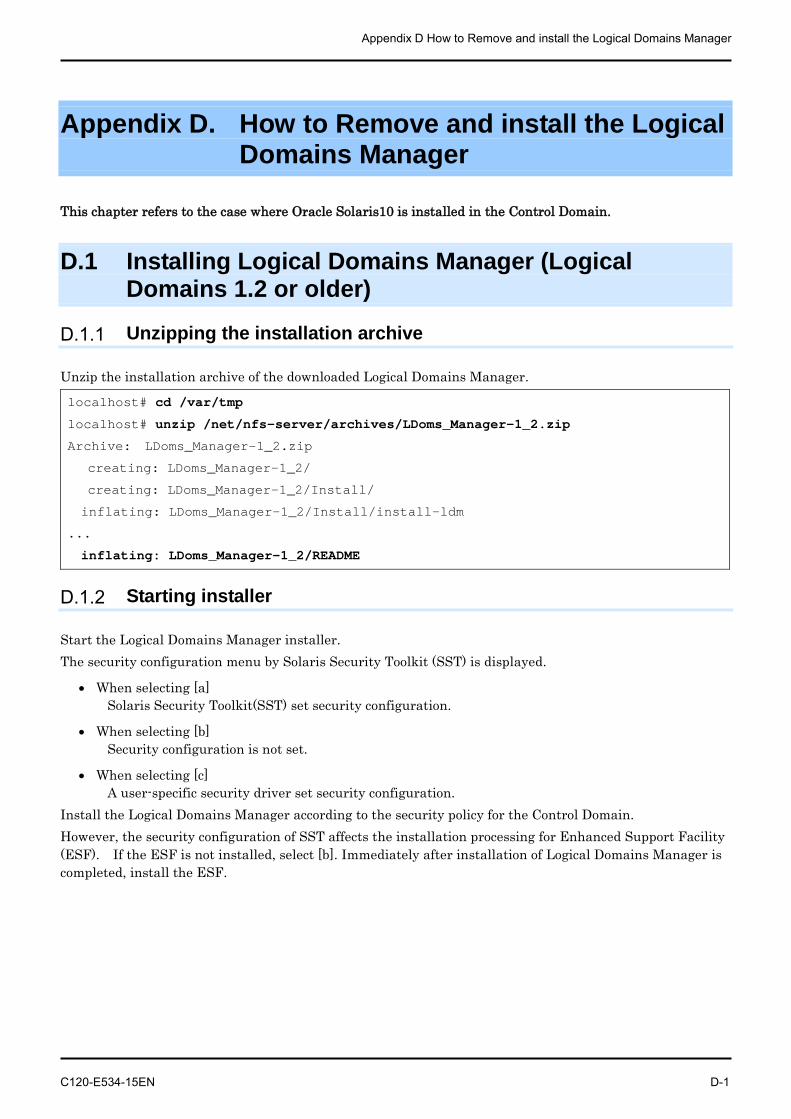
Appendix D How to Remove and install the Logical Domains Manager
C120-E534-15EN D-1
Appendix D. How to Remove and install the Logical Domains Manager
This chapter refers to the case where Oracle Solaris10 is installed in the Control Domain.
D.1 Installing Logical Domains Manager (Logical Domains 1.2 or older)
D.1.1 Unzipping the installation archive
Unzip the installation archive of the downloaded Logical Domains Manager.
localhost# cd /var/tmp
localhost# unzip /net/nfs-server/archives/LDoms_Manager-1_2.zip
Archive: LDoms_Manager-1_2.zip
creating: LDoms_Manager-1_2/
creating: LDoms_Manager-1_2/Install/
inflating: LDoms_Manager-1_2/Install/install-ldm
...
inflating: LDoms_Manager-1_2/README
D.1.2 Starting installer
Start the Logical Domains Manager installer. The security configuration menu by Solaris Security Toolkit (SST) is displayed.
• When selecting [a] Solaris Security Toolkit(SST) set security configuration.
• When selecting [b] Security configuration is not set.
• When selecting [c] A user-specific security driver set security configuration.
Install the Logical Domains Manager according to the security policy for the Control Domain. However, the security configuration of SST affects the installation processing for Enhanced Support Facility (ESF). If the ESF is not installed, select [b]. Immediately after installation of Logical Domains Manager is completed, install the ESF.
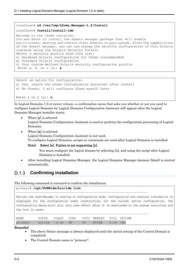
D.1 Installing Logical Domains Manager (Logical Domains 1.2 or older)
D-2 C120-E534-15EN
localhost# cd /var/tmp/LDoms_Manager-1_2/Install
localhost# Install/install-ldm
Welcome to the LDoms installer. You are about to install the domain manager package that will enable you to create, destroy and control other domains on your system. Given the capabilities of the domain manager, you can now change the security configuration of this Solaris instance using the Solaris Security Toolkit. Select a security profile from this list: a) Hardened Solaris configuration for LDoms (recommended) b) Standard Solaris configuration c) Your custom-defined Solaris security configuration profile Enter a, b, or c [a]: a
Select an option for configuration: y) Yes, launch the LDoms Configuration Assistant after install n) No thanks, I will configure LDoms myself later Enter y or n [y]: n
In Logical Domains 1.2 or newer release, a confirmation menu that asks you whether or not you need to configure Logical Domains by Logical Domains Configuration Assistant will appear after the Logical Domains Manager installer starts.
• When [y] is selected Logical Domains Configuration Assistant is used to perform the configuration processing of Logical Domains.
• When [n] is selected Logical Domains Configuration Assistant is not used. To configure Logical Domains, scripts or commands are used after Logical Domains is installed. Note) Select [n]. Fujitsu is not supporting [y].
You must configure the logical domain by selecting [n], and using the script after Logical Domains is installed.
• After installing Logical Domains Manager, the Logical Domains Manager daemon (ldmd) is started automatically.
D.1.3 Confirming installation
The following command is executed to confirm the installation. primary# /opt/SUNWldm/bin/ldm list --------------------------------------------------------------------- Notice: the LDom Manager is running in configuration mode. Configuration and resource information is displayed for the configuration under construction; not the current active configuration. The configuration being built will only take effect after it is downloaded to the system controller and the host is reset. --------------------------------------------------------------------- NAME STATE FLAGS CONS VCPU MEMORY UTIL UPTIME primary active -n-cv SP 64 8064M 0.1% 16m
Remarks) • The above Notice message is always displayed until the initial setting of the Control Domain is
completed. • The Control Domain name is "primary".
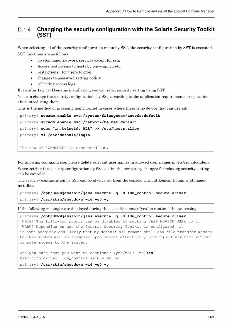
Appendix D How to Remove and install the Logical Domains Manager
C120-E534-15EN D-3
D.1.4 Changing the security configuration with the Solaris Security Toolkit (SST)
When selecting [a] of the security configuration menu by SST, the security configuration by SST is executed. SST functions are as follows.
• To stop major network services except for ssh. • Access restrictions to hosts by tcpwrapper, etc. • restrictions for users to cron. • changes to password setting polic.y • collecting access logs.
Even after Logical Domains installation, you can relax security setting using SST. You can change the security configurations by SST according to the application requirements or operations after introducing them. This is the method of accessing using Telnet in cases where there is no device that can use ssh.
primary# svcadm enable svc:/system/filesystem/autofs:default
primary# svcadm enable svc:/network/telnet:default
primary# echo "in.telnetd: ALL" >> /etc/hosts.allow
primary# vi /etc/default/login
The row of "CONSOLE" is commented out.
For allowing command use, please delete relevant user names in allowed user names in /etc/cron.d/at.deny. When setting the security configuration by SST again, the temporary changes for relaxing security setting can be canceled. The security configuration by SST can be always set from the console without Logical Domains Manager installer.
primary# /opt/SUNWjass/bin/jass-execute -q -d ldm_control-secure.driver
primary# /usr/sbin/shutdown -i6 -g0 -y
If the following messages are displayed during the execution, enter "yes" to continue the processing.
primary# /opt/SUNWjass/bin/jass-execute -q -d ldm_control-secure.driver [NOTE] The following prompt can be disabled by setting JASS_NOVICE_USER to 0. [WARN] Depending on how the Solaris Security Toolkit is configured, it is both possible and likely that by default all remote shell and file transfer access to this system will be disabled upon reboot effectively locking out any user without console access to the system. Are you sure that you want to continue? (yes/no): [no]Yes Executing driver, ldm_control-secure.driver
primary# /usr/sbin/shutdown -i6 -g0 -y
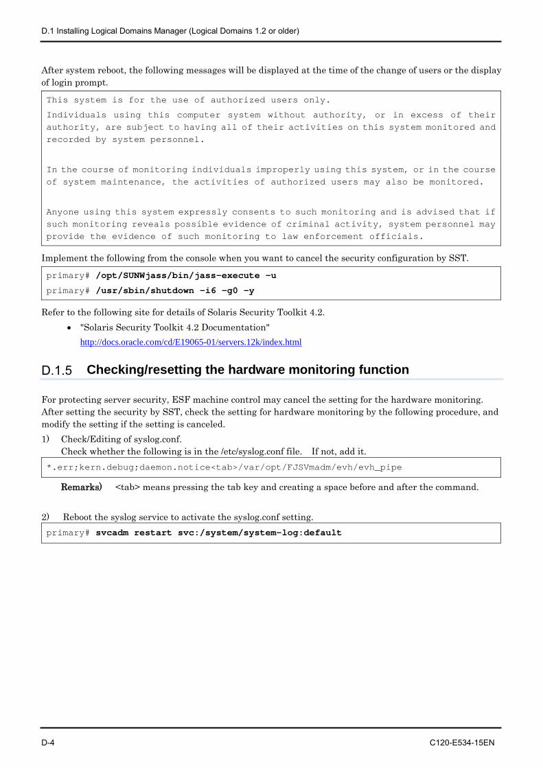
D.1 Installing Logical Domains Manager (Logical Domains 1.2 or older)
D-4 C120-E534-15EN
After system reboot, the following messages will be displayed at the time of the change of users or the display of login prompt.
This system is for the use of authorized users only.
Individuals using this computer system without authority, or in excess of their authority, are subject to having all of their activities on this system monitored and recorded by system personnel.
In the course of monitoring individuals improperly using this system, or in the course of system maintenance, the activities of authorized users may also be monitored.
Anyone using this system expressly consents to such monitoring and is advised that if such monitoring reveals possible evidence of criminal activity, system personnel may provide the evidence of such monitoring to law enforcement officials.
Implement the following from the console when you want to cancel the security configuration by SST.
primary# /opt/SUNWjass/bin/jass-execute -u
primary# /usr/sbin/shutdown -i6 -g0 -y
Refer to the following site for details of Solaris Security Toolkit 4.2. • "Solaris Security Toolkit 4.2 Documentation"
http://docs.oracle.com/cd/E19065-01/servers.12k/index.html
D.1.5 Checking/resetting the hardware monitoring function
For protecting server security, ESF machine control may cancel the setting for the hardware monitoring. After setting the security by SST, check the setting for hardware monitoring by the following procedure, and modify the setting if the setting is canceled. 1) Check/Editing of syslog.conf.
Check whether the following is in the /etc/syslog.conf file. If not, add it. *.err;kern.debug;daemon.notice<tab>/var/opt/FJSVmadm/evh/evh_pipe
Remarks) <tab> means pressing the tab key and creating a space before and after the command.
2) Reboot the syslog service to activate the syslog.conf setting. primary# svcadm restart svc:/system/system-log:default
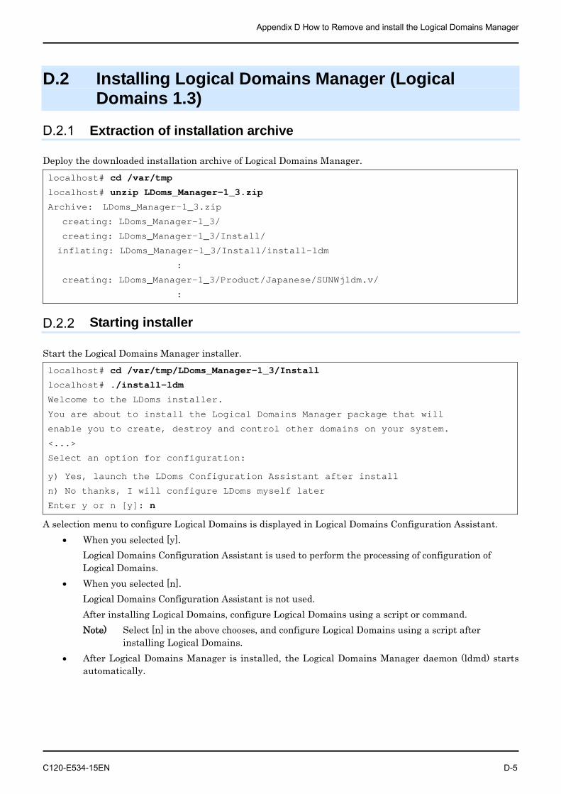
Appendix D How to Remove and install the Logical Domains Manager
C120-E534-15EN D-5
D.2 Installing Logical Domains Manager (Logical Domains 1.3)
D.2.1 Extraction of installation archive
Deploy the downloaded installation archive of Logical Domains Manager. localhost# cd /var/tmp
localhost# unzip LDoms_Manager-1_3.zip
Archive: LDoms_Manager-1_3.zip
creating: LDoms_Manager-1_3/
creating: LDoms_Manager-1_3/Install/
inflating: LDoms_Manager-1_3/Install/install-ldm
:
creating: LDoms_Manager-1_3/Product/Japanese/SUNWjldm.v/
:
D.2.2 Starting installer
Start the Logical Domains Manager installer. localhost# cd /var/tmp/LDoms_Manager-1_3/Install
localhost# ./install-ldm
Welcome to the LDoms installer.
You are about to install the Logical Domains Manager package that will
enable you to create, destroy and control other domains on your system.
<...>
Select an option for configuration:
y) Yes, launch the LDoms Configuration Assistant after install
n) No thanks, I will configure LDoms myself later
Enter y or n [y]: n
A selection menu to configure Logical Domains is displayed in Logical Domains Configuration Assistant. • When you selected [y].
Logical Domains Configuration Assistant is used to perform the processing of configuration of Logical Domains.
• When you selected [n]. Logical Domains Configuration Assistant is not used. After installing Logical Domains, configure Logical Domains using a script or command. Note) Select [n] in the above chooses, and configure Logical Domains using a script after
installing Logical Domains. • After Logical Domains Manager is installed, the Logical Domains Manager daemon (ldmd) starts
automatically.

D.2 Installing Logical Domains Manager (Logical Domains 1.3)
D-6 C120-E534-15EN
D.2.3 Confirming installation
The following command is executed to confirm the installation. primary# /opt/SUNWldm/bin/ldm list-domain NAME STATE FLAGS CONS VCPU MEMORY UTIL UPTIME primary active -n-c-- SP 256 65248M 0.2% 8m
Remarks) The Control Domain name is primary.
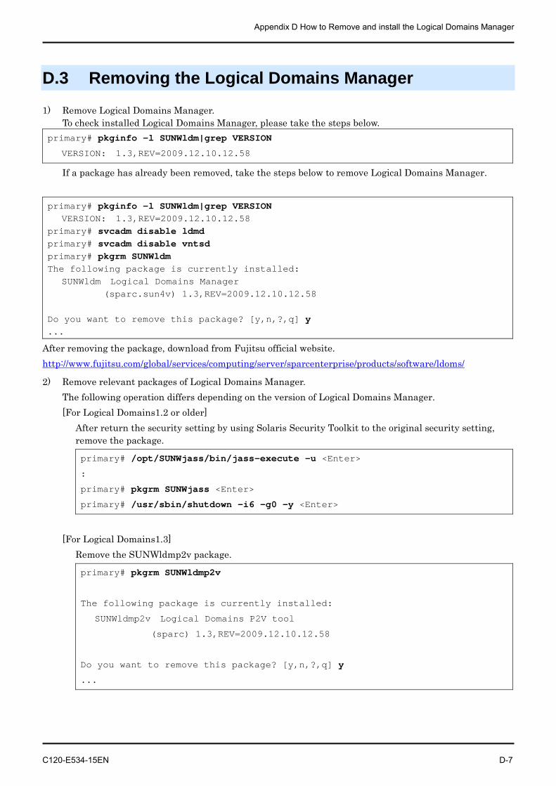
Appendix D How to Remove and install the Logical Domains Manager
C120-E534-15EN D-7
D.3 Removing the Logical Domains Manager
1) Remove Logical Domains Manager. To check installed Logical Domains Manager, please take the steps below.
primary# pkginfo -l SUNWldm|grep VERSION
VERSION: 1.3,REV=2009.12.10.12.58
If a package has already been removed, take the steps below to remove Logical Domains Manager.
primary# pkginfo -l SUNWldm|grep VERSION VERSION: 1.3,REV=2009.12.10.12.58 primary# svcadm disable ldmd primary# svcadm disable vntsd primary# pkgrm SUNWldm The following package is currently installed: SUNWldm Logical Domains Manager (sparc.sun4v) 1.3,REV=2009.12.10.12.58 Do you want to remove this package? [y,n,?,q] y ...
After removing the package, download from Fujitsu official website. http://www.fujitsu.com/global/services/computing/server/sparcenterprise/products/software/ldoms/
2) Remove relevant packages of Logical Domains Manager. The following operation differs depending on the version of Logical Domains Manager. [For Logical Domains1.2 or older]
After return the security setting by using Solaris Security Toolkit to the original security setting, remove the package.
primary# /opt/SUNWjass/bin/jass-execute -u <Enter>
:
primary# pkgrm SUNWjass <Enter>
primary# /usr/sbin/shutdown -i6 -g0 -y <Enter>
[For Logical Domains1.3]
Remove the SUNWldmp2v package.
primary# pkgrm SUNWldmp2v
The following package is currently installed:
SUNWldmp2v Logical Domains P2V tool
(sparc) 1.3,REV=2009.12.10.12.58
Do you want to remove this package? [y,n,?,q] y
...